Embed Size (px)
Citation preview
Wide-Field Imaging Survey Polarimeter(WISP)
Target:
UVX7
Experimenter's Data Package
Vehicle
36.172 UG
Revision HApr 6, 1999
Prepared for:
National Aeronautics and Space AdministrationWallops Flight Facility
Wallops Island, Virginia
Prepared by:
K. H. Nordsieck & W. M. HarrisSpace Astronomy Laboratory
University of WisconsinMadison, Wisconsin 53706

WISP-IV EDP: 36.172 UG Rev H Apr 6, 1999 i
Change History
Rev Date Description
F 18 Oct, 1998 Made UVX7 primary target with UVX6 backup. Incorporatedelectronic versions of all figures. Launch windows Nov 1998 - Jan1999
G 13 Feb, 1999 Removed UVX6. Updated launch windows to Mar - May 1999
H 6 Apr, 1999 MRR: Add integration status; revise success criteria

WISP-IV EDP: 36.172 UG Rev H Apr 6, 1999 1
1. Description of Experiment
The Wide-Field Imaging Survey Polarimeter (WISP) is a suborbital rocket payload that hasbeen used to obtain the first wide-field polarimetric and photometric images of astronomicalnebulae in the vacuum ultraviolet. The WISP instrument is designed to study the properties andgeometric distribution of diffuse dust in our Galaxy and nearby galaxies; its wide field of viewand high sensitivity also make in an excellent instrument for the study of diffuse emission in thezodiacal light and in the extended coma and tail of a comet. The first three successful flights ofWISP have covered different representative objects in these categories, a local star cluster (thePleiades - Vehicle 36.050 UG), a nearby galaxy (the Large Magellanic Cloud- Vehicle 36.128UG), and a comet (Hale-Bopp- Vehicle 36.157 UL). For the upcoming mission our target is adirection in our Galaxy, "UVX7" (the "Sandage Area" near the external galaxies M81 and M82)that was identified as bright by previous UV diffuse light survey missions. If this light is due toreflection of UV starlight from Galactic interstellar dust, as has been commonly assumed, thelight should be highly polarized, and the polarization angle should identify the illuminator,allowing a reconstruction of the path taken by the light, and a measurement of the properties ofthe dust.
The payload configuration for this mission will be similar that used for the first three WISPmissions, with the exception of changes to the detector, replacement of the tracker "apertureplate" with a standard shutter door, and the inclusion of a prototype aspect camera/star trackerthat we are currently developing for our new rocket instrument, FUSP. The WISP opticalpackage (Figure 1) is a wide-field F/1.9 off-axis Schmidt telescope with a polarizing Brewster-angle mirror and a waveplate modulator. Light from the target field enters the experiment at anangle of 40E from the vehicle spin axis. The octagonal-shaped aperture is covered by a doorduring launch and re-entry. The first optical element is the "stressed waveplate", which is arotatable CaF2 plate with a programmable birefringence introduced by pneumatic actuators ontwo edges. This effectively rotates the plane of polarization of the incoming light, depending onthe angle and the stress applied, which is controlled by the experiment processor based on straingages. The light then encounters an off-axis Schmidt corrector mirror and a large flat mirrorcoated with a high-index monolayer, which polarizes the light by the Brewster effect. Finally thelight is focused by a spherical primary mirror and imaged on a Charge-Coupled Device (CCD)detector. The CCD is preceded by a color filter slide (two filters are available), a shutter, and afield flattener/window. The CCD is cooled to -80EC by a Thermo-Electric Cooler (TEC), whichdischarges its heat into a copper heat sink on the rear of the evacuated housing. The heat sink iscooled to about -40EC by liquid N2 boil-off up until launch. The entire optical area is also purgedwith dry argon up until launch for cleanliness and to prevent condensation on the CCD window.
The first two WISP missions called for two Attitude Control System startrackers, with tracker#1 aligned to the spin axis, and #2 (the "side tracker") pointed near the experiment line of sight ata trackable star. There are also two "sky monitors", miniature telescopes which focus the WISPfield of view onto photomultipliers with fixed UV filters, mounted beside the startrackers. Thesky monitor signals are used in post-mission analysis to calibrate the residual UV airglow andzodiacal light background. The trackers and sky monitors have been protected during landing bya guillotine "aperture plate"; for this mission the aperture plate will be replaced by a standardshutter door. The forward startracker is used to update the vehicle gyros and to slew to thecorrect experiment orientation; control was then switched to the side startracker for accuratetracking during the science exposure. Our choice of a moving target (comet Hale-Bopp) for the

WISP-IV EDP: 36.172 UG Rev H Apr 6, 1999 2
last mission, made the use of a the second tracker problematic, because a different trackable starwas needed on each night of the launch window. Our approach was to align the second trackerfor a single night of the window. When we failed to launch on this date, we were forced toabandon the second tracker, and accept the errors associated with gyro drift roll. To our pleasantsurprise, our data quality was not compromised by this, and we now plan to eliminate the sidetracker in future flights. This greatly simplifies instrument alignment and limits the risk to thedwindling supply of trackers in the sounding rocket program arsenal.
A data sequence through one experiment filter consists of four exposures of the CCD withdifferent stress and angle states of the waveplate. The Hale-Bopp and Pleiades missions usedboth available filter positions, resulting in a total of 8 science exposures. To maximize thesignal/noise in the diffuse target for the upcoming flight(s), we plan to use a single filter/launch. The CCD readout bins 5×5 pixels into one, giving a ~1 arcmin effective pixel size. Eachexposure will be roughly 80 seconds in length, with an additional 4 seconds required for CCDreadout and mechanism operations. The exposures are differenced in later processing to obtainthe polarimetric images.
2. Electronics
The experiment system and electronics block diagrams are shown in Figures 2 and 3, andinclude the changes expected for the upcoming mission. In particular, we will install a new CCDdetector/controller, will interface to the new startracker door, and will include a prototype for anew star-tracker/aspect camera that we are currently developing. These changes are discussed indetail below. All of the major experiment electronics are located in a separate electronics sectionof the experiment. The Dedicated Experiment Processor (DEP) controls the waveplatepneumatics and rotator, the filter and shutter, the focus mechanism, and the CCD detector basedon internally stored sequences and two payload-generated signals, an "aspect picture" request ofthe experiment CCD from the ACS, and an "on target" signal from the ACS. The DEP alsocontrols the CCD temperature by controlling the TEC current. All experiment system power isregulated from the vehicle 28V bus. Experiment outputs include a dedicated digital telemetrystream at 2 Mbit/s; the DEP will multiplex this data into a serial data channel complete with therequired synch words. In addition, a number of analog monitors (see Interface Specification,attached) will be fed to the vehicle multiplexer to provide system status independent of the DEP. The experiment door and tracker door will be controlled directly by the payload timer.
3. Structure
The experiment structure conforms to the standard 17.26 inch diameter bulkhead/skin. Totalpayload weight is ~770 lbs, broken down approximately as follows:
Item Weight (lbs)
Nose cone 21.6
ORSA (750 lb) 87.4
Offset Adaptor 5.5
Upper Balance Wt 11
ACS (Mk VI) 112

WISP-IV EDP: 36.172 UG Rev H Apr 6, 1999 3
Item Weight (lbs)
Telemetry 82
S19 70
Experiment 302
Main 174.7 (See Table 1)
Cables/Baffling 20
Misc 25
Skins 64.2
Experiment Door 10
Tracker Plate/Door 5
Lower Balance Wt 11
Ignitor 52.6
Thrust Term 13.8
Total 766
An outline of the experiment section is shown in Figure 4. Detailed weight and center of gravityestimates are listed in presented as determined for the previous mission. The experimentcoordinate system used in Table 1 is as follows:
Exp ACS Direction On Pad Zero
X -Yaw Perpendicular to the spin axis, opposite the door West Spin Axis
Y -Roll Along spin axis, along LOS of startracker #1 Down Exp/TLM I/F
Z -Pitch Perpendicular to the spin axis, along ACS 0 South Spin Axis
Note that in this coordinate system, the experiment LOS is not along X, Y, or Z, but is ratherdisplaced from Y by a +40E rotation about the +Z axis, or an ACS pitch of -40E.
4. Experiment History
1) 36.050 UG: The payload has flown previously on December 2/3, 1994. The mission was asuccess, with three anomalies:
- ACS roll stability on the science target was degraded.
- ACS pointing error in the roll direction was 22 arcmin
- Experiment detector noise was about 50% higher than anticipated.
The first two anomalies were traced to a wiring problem in the ACS and were corrected inadvance of the second flight.
2) 36.128 UG: The payload was flown on November 17, 1995. This mission was a completesuccess with the following anomalies which did not significantly affect flight performance:

WISP-IV EDP: 36.172 UG Rev H Apr 6, 1999 4
- Thermal noise in the experiment detector was higher than expected for the temperaturerecorded within the housing.
- We were unable to cool the back plate to the desired temperature due to a low temperature leakin the evacuated housing.
The causes of these anomalies were identified. The thermal noise was determined to becorrelated with higher than normal water levels inside the detector, which caused a well knowndetector problem where ice formation in the space between the CCD and cold sink creates athermal insulating wall. Since our temperature sensor was attached to the cold sink, we weregiven an erroneous signal for the temperature of the detector. The source of the low temperatureleak was not specifically identified, however we were able to fix it by replacing all of the sealingO-rings with new ones optimized for low temperature operation.
3) 36.157 UL: The payload was flown on April 8, 1997 to observe comet Hale-Bopp. Thismission was a comprehensive technical and scientific success with two anomalies.
- Our initial launch attempt was aborted due to a failure in the camera shutter 3 minutes beforelaunch.
- During the flight we noted some significant increasing in sky background noise from whatappear to be multiple sky background sources.
The primary anomaly for this mission was the shutter failure. We were able to isolate thisfailure to a slowly decreasing tension on a restoring spring in the shutter assembly. When thedetector was cooled, either ice formation or shifting/warping of the shutter blades froze themechanism. We added a new spring that more than doubled the restoring force and made thesystem highly reliable from that point on. We have implemented new protocols to monitorshutter performance before and during flight. The sky background anomaly may have been dueto the low elevation of the target for this flight, however, since it was greatest in the last image,we plan to terminate the last exposure at a higher altitude, and then look at the zenith in anattempt to measure what we believe to be an airglow feature.
5. Experiment Modifications
1) Upgrade to the CCD detector: As part of the preparation for this mission we plan to replacethe current WISP CCD with a new controller/detector combination. The current 1200x400 pixelReticon CCD and controller will be replaced with a modern 1024x1024 SITe device that willmore than double quantum efficiency and reduce read noise by more than a factor of 2. Thissystem will be enclosed in a new, better sealed, detector housing with an upgraded thermo-electric cooler that will permit lower temperature operation. From an interface to NASAperspective, there will be no difference between this device and the current detector.
2) Replacement of the tracker "aperture plate" with a standard shutter door. Due to repeateddamage to the startracker during past landings, the experiment was requested to replace thesimple "guillotine" type tracker shutter with a standard shutter door. This has beenaccommodated by the addition of a connector (P750; see Interface Specification, attached), andthe rewiring of the Ignitor Housing connector (J5). Note that in this document, the shutter door
WISP-IV EDP: 36.172 UG Rev H Apr 6, 1999 5
protecting the tracker is referred to as the "Tracker Door", and the shutter door protecting theexperiment optics is the "Experiment Door". Both are sometimes referred to as the "ShutterDoor" in vehicle documentation, and our terminology is preferred to prevent confusion.
3) Incorporation of a prototype aspect camera/star tracker: We are planning to replace the nowredundant second star tracker with a new device that we are developing for our second payload(FUSP: 36.173 UG). This device will be installed in the area occupied by tracker 2 and will bebore-sighted to tracker 1. This unit is capable of providing simultaneous centroiding data similarto the current Ball tracker and compressed image output. We will modify our current harness todownlink the centroiding data for post-flight analysis, and these signals will be incorporated intoour engineering data stream (no changes in the TM system are required to accommodate this). Also, we are requesting that the vehicle TM system be modified to accept and transmit 38400baud RS232 serial telemetry from this device. We do not intend to use this device for trackingon this mission.
6. Experiment Events
The experiment is controlled entirely by preplanned sequences and the timer- and ACS-basedsignals. The experiment requirements for these signals are as follows (Electrical interface detailsare given in the Telemetry, Commands, and Electrical Interface Specification Attached):
Event Origin Requirement
On Target ACS Leave on.
Exp Power Off Timer Parachute deploy - 20 sec.
Table 2 gives an experiment event program based on a nominal apogee altitude of 375 kmand an ACS "on target" at T+161 (nominal); T+187 (latest) seconds. The low voltage logicpower will be on at lift-off and telemetry will be continuous. CCD dark frames commence ondespin. The high voltage powering the mercury focus testlamp and the sky monitors will beturned on at T+96 seconds, controlled by the experiment internal timer. Science exposures beginon receipt of "On Target" from the ACS. If the "On Target" is not received, science exposuresbegin automatically at T+187 seconds, the latest time for this signal, with the entire imagingsequence. Regardless of the timing of the ‘On Target’ signal (or lack thereof) the entire imagesequence is designed to fill the time until an altitude of 106 km is reached. This will consist offour science images, which will end at altitude ~180 km, plus a low-altitude sky backgroundimage. High voltage is turned off at experiment door close and CCD dark frames are thencontinued until experiment power off.
The protoype camera/ startracker will be controlled by the ACS signals that were used for the"side" tracker in previous missions. The current wiring harness causes the FOV and brightness("Cmd") controls to be shared between the main Ball ("forward") tracker and the UW tracker, sothese will be used on a non-interference basis. As summarized in the table below, during gyroupdate star #1 and #2 fine modes, we require an acquisition signal. We assume that neitherlimited FOV bits will be asserted. At the end of each gyro update star fine mode, we require anextra step, longer than 0.25 s, when the Ball tracker- based fine mode continues but the UWtracker acquire is removed (this is for acquisition of a stable aspect image). During the on-target

WISP-IV EDP: 36.172 UG Rev H Apr 6, 1999 6
period on the science target, we require a UW tracker acquire signal, plus FOV and Cmd signalsas shown below.
Event BallAcq
UWAcq
2E FOV 4E FOV Cmd 1 Cmd 2 Time
GS #1,
GS #2
On On 0V 0V don't care don't care Fine mode
On Off 0V 0V don't care don't care >0.25 s
Off Off don't care don't care don't care don't care
Science Off On 28V 28V GND OPEN On Target
7. Pointing Requirements:
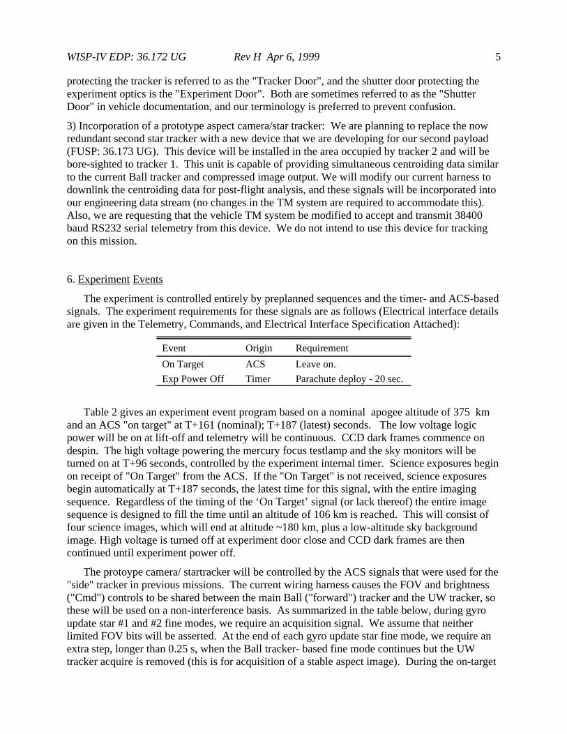
We made starmaps for UVX7 (Figures 5a,b) and windows for each month starting in March1999 and ending in May, 1999 (Table 3). The windows are defined by a combination of time ofnight, elevation of target, angular separation of the target from the moon, and the distance of theSun below the depressed horizon. The roll for UVX7 was chosen to optimize the placement ofthe known diffuse clouds as seen by IRAS. The position of the target area is given below. Thewindows are chosen for an optimal launch after midnight.
UVX7
Position RA (J2000) 09h 40m 00s
DEC (J2000) 70E 00' 00"
Roll 90E
Window: 0 - 2h MST, 14 - 19 Mar, 1999
1 - 2h MDT, 12 - 17 Apr, 1999
0 - 1h MDT, 10 - 15 May, 1999
Experiment roll is defined as the angle measured clockwise (looking at the experiment LOS)from North (J2000 coordinates) to the ACS 0 (experiment Z axis). As noted above, there is a 40Eoffset between the startracker axis and the experiment axis. During science exposures thestartracker (-Roll axis), and the ACS pitch axis are then pointed at
UVX7
Tracker LOS RA (J2000) 9h 40m 00s
Dec (J2000) 30E 00' 00"
ACS +Pitch Axis
RA (J2000) 15h 40m 00s
Dec (J2000) 00E 00' 00"
Figure 5a,b shows the starchart containing the experiment and startracker lines-of-sight forUVX7. Stars down to 3rd magnitude are shown in the wide field, identified by SAO number. Pointing accuracy is to be ±0.1E in experiment LOS and ±1E in experiment roll. Pointingstability is to be < 60 arcsec rms diameter for 85 seconds (the duration of one exposure).

WISP-IV EDP: 36.172 UG Rev H Apr 6, 1999 7
8. Launch Window Requirements
Launch window criteria are based on minimization of the risk of sunlight hitting theexperiment or trackers in flight and celestial/terrestrial backgrounds. They are:
1) Target Zenith Distance (ZD) < 25E
2) Sun > 30E below depressed horizon at Apogee
3) Moon > 20E below depressed horizon at Apogee
4) Launches after local midnight are preferred to minimize airglow.
Windows for March - May, 1999 are shown in Table 3. The current nominal Launch time is0100 MDT on the night of April 12/13, 1999 (shown as "N" in table 3).
9. Comprehensive Mission Success Criteria
1) Vehicle: 835 lb to nominal apogee minimum
2) ACS: experiment LOS pointing error < 0.15E.
" " stability/100s < 60 " (rms diameter).
3) Experiment: All science exposures obtained.
4) Payload recovered in good condition.
10. Minimum Success Criteria
1) Vehicle: 835 lb to a minimum of 3s below nominal apogee.
2) ACS: experiment LOS pointing error < 0.3E.
" " stability/100s < 120 " (rms diameter).
3) Experiment: All science exposures obtained.
11. Support Requirements
1) Purge gas: A continuous low pressure (2-3 psig) flow of dry argon is to be maintained intothe experiment optical section, venting into the experiment electronics section and into thestartracker section. We estimate a maximum consumption of one high pressure bottle every twodays when the experiment is integrated into the payload.
2) Detector coldsink coolant: A 35 liter liquid nitrogen dewar will be located underneath thelauncher, attached to the payload coolant pullaway by approximately 60 ft of insulated coolantline. The experimenter will provide the dewar, coolant line, and pullaway mechanism. Weestimate a maximum consumption of 5 liters per cooldown cycle (detector coldsink from 20EC to-40EC in 30 minutes), and 3 liters/hour to maintain -40EC prior to launch. The dewar should betopped off each night a launch is attempted. In addition, one standard high pressure gaseousnitrogen bottle will be required underneath the launcher to back pressurize the LN2 dewar if

WISP-IV EDP: 36.172 UG Rev H Apr 6, 1999 8
necessary. The experimenter will provide a regulator to drop the gaseous nitrogen to lowpressure (10 psig). The cooling system was operational at all times (including during arming) forthe Hale-Bopp mission, and we are requesting the same operational status for the upcomingmission.
3) Environmental control: The experiment section of the payload skin (70" length) should beenclosed in a thermally controlled enclosure. The temperature should be maintained at 20EC ±5EC from T-6 hours until launch.
4) Access to experiment prior to launch: While the experiment is horizontal the experimenterrequires access via the electronics section access door to refill the waveplate system highpressure tank and to connect a portable vacuum pump system to the detector head vacuum line. The high pressure tank will require refilling on an as-needed basis prior to each night's launchattempt. It is anticipated that the detector head will be pumped down continuously to maintain anoptimum vacuum. The pump will be external to the payload, electrically isolated and on anuninterruptable power supply. It will be turned off and disconnected just prior to taking the railvertical.
12. Flight Qualification Status
In March-April the integrated payload underwent Testing and Integration at University ofWisconsin and WSMR. The following issues were identified:
- The experiment processor sometimes fails to start its timeline at T-60 secs. This is due to anunidentified software error. The workaround is to cycle power to the instrument, re-equilibratethe detector cooling, and re-start the timeline. This procedure was exercised in the RangeHorizontal Test and found to take less than 5 minutes, with no impact on the rest of the flight.
- The experiment processor does not restart during the power backup test. Since power cycle atlaunch is an extremely rare occurrence, we elect to fly as is.
- The experiment is now taking about 10 minutes longer to reach flight detector temperature. Once it is reached, all else is nominal. This will require going vertical 10 minutes earlier.
- The prototype star tracker roll analog telemetry is not being transmitted, apparently due to awiring error in the experiment. Since roll data is available in the digital telemetry, we will fly asis.
13. Redundant Systems
Other than redundant batteries on the experiment system timer board, there are no redundanthardware systems. There are fallback software routines within the experiment processor that willbe used in the event of certain hardware failures. For instance, in case the processor is reset by apower glitch, the processor will check the system timer and resume the observing program fromthe pre-programmed time table stored in ROM.

WISP-IV EDP: 36.172 UG Rev H Apr 6, 1999 9
14. History of Items to be Flown
The flight hardware was flown on 36.050UG in December 1994, on 36.128UG in November1995, and in April 1997 as 36.157UL.
15. Experimenter's Launch Criteria
Launch criteria are based entirely on the preplanned launch window requirements (section 7above) and on experiment health. All experiment health measurements are available to theexperiment processor, so that experiment health will be judged based on performance of anexperiment self-test during the launch count-down.
16. Interface Requirements
See Attachment 1 (Telemetry, Commands, and Electrical Interface Specification,WP1100-S-0010 Rev E) for electronic interface requirements.
17. Special Requests:
To support our apogee requirements we are requesting enhanced launch vehicle (Mark 70)for our flight. This would be a repeat of the vehicle configuration for 36.157UL.

WISP-IV EDP: 36.172 UG Rev H Apr 6, 1999 10
Table 1. Mass and Center of Gravity Estimates
Pcs Part # Name Wt Ea Total Method X(") Y(") Z(")1 Assy Optics Section: 78 lb 78 Actual -2.4 34.75 0
5087 Brewster Mirror5085 Primary Mirror5084 Corrector Mirror5022 Detector Assembly5016 Detector Rails5030 Primary Bulkhead5029 Corrector Bulkhead5005,9 Vertical Rails/Supports5093 Brewster Flex Beams5018,27 " Supports5077 Corrector Mount5076 Primary Mount
Optics/Electr. Flange1 Assy Electronics Section: 55 55 Actual 0.25 8.25 0
STD Card Cage5017 Electr Base Plate5105 Electr Supp Legs5046 Detector Electr5104,5 Pwr Supply/Distr Box
Power CubesPneumatic SystemSystem Timer Box
1 Assy Waveplate Assy 7.0 7.0 Est -4.0 30.8 01 #1 Star Tracker 11 11 Est -5.8 58.8 01 " Mount 1.2 1.2 Act -5.5 58.8 01 Prototype Tracker 8 8 Est 2.0 58.8 01 " Mount 4.4 4.4 Est 2.0 58.8 01 Sky Mon Electr Box 1.0 1.0 Est 0 56 02 Sky Monitor 2.1 4.2 Act 0 58.3 02 " Mount 1.2 2.4 Act 0 57.3 01 Str Gage Amp Box 1.0 1.0 Est 0 41.8 6.31 Lamp Power Supply 1.5 1.5 Est 0 26.8 6.3
Center of Mass X -1.275 "
Y 29.74 "
Z 0.084 "
Total Weight 174.7 lbs

WISP-IV EDP: 36.172 UG Rev H Apr 6, 1999 11
Table 2. Preliminary Flight Timeline for UVX7
/* Flight Timeline for WISP 36.172UG */
/* Target: UVX-6 */
/* Revision 1: 29 July 1998 */
/* Clock start at t-60 secs */
/* Short Wavelength exposure only */
/* No focus motion */
/* Start mechanism motions 2 sec after */
/* beginning of readout */
/* All images 4x4 bin full image */
/* TEC FLIGHT=4 , filter hold launch or reentry */
TL_VERSION 4
BEGIN -60
PARAMETER -60
PRIMARY_GAUGE A
SECONDARY_GAUGE B
PRESSURE0 000 /* zero pressure */
PRESSURE1 400 /* launch pressure */
PRESSURE2 1800 /* half-wave short wavelength */
PRESSURE3 2900 /* half-wave long wavelength */
PRESSURE4 0
PRESSURE5 0
PRESSURE6 0
PRESSURE7 0
TL_TYPE FLIGHT
OFFSETA 860
OFFSETB 890
OFFSETC 803
OFFSETD 817
CAM -59
SBIN 4
PBIN 4
SREADLEN 281
PREADLEN 256
TAKE -58 /* 3 sec dark, 4x4 binning */
EXPTYPE DARK
SECONDS 3
TAKE -52 /* prelaunch 40-sec dark */
EXPTYPE DARK
SECONDS 40
MECH -46 /* launch mech preps during CCD dark */
FILTER B /* short wavelength */
PRESSURE 1 /* launch pressure */
ROTATION 0
SKYMON ON
TEC 4
VALVE ENABLE
MECH -15 /* launch mech preps - II */
FILTER HOLDB
PRESSURE 1
ROTATION 0
SKYMON ON
TEC 4
VALVE DISABLE /* disable control for launch */
TAKE -9
EXPTYPE BIAS
CAM 48 /* 4x4 cam mode again, for safety */
SBIN 4
PBIN 4
SREADLEN 281
PREADLEN 256
TAKE 48 /* bias */
EXPTYPE BIAS
TAKE 52
EXPTYPE DARK
SECONDS 40 /* will finish at 90 */
MECH 75
FILTER B /* P/L sep at 64- filter hold off */
PRESSURE 0
ROTATION 0
SKYMON ON /* Skymon On */
TEC 4
VALVE ENABLE /* re-enable valves */
LAMP OFF
MECH 96
FILTER A /* longwave for focus */
PRESSURE 0
ROTATION 0
SKYMON ON
TEC 4
VALVE ENABLE
LAMP ON /* lamp on for focus */
CAM 96 /* 2x2 centered images */
SBIN 2
PBIN 2
SORIGIN 256
PORIGIN 256
SREADLEN 256
PREADLEN 256
TAKE 96
EXPTYPE NORMAL
SECONDS 1
MECH 102 /* MECH for first science exposure */
FILTER B
PRESSURE 0
ROTATION 0
SKYMON ON
TEC 4
VALVE ENABLE
LAMP OFF /* lamp off */
CAM 102 /* 4x4 dark */
SBIN 4
PBIN 4
SREADLEN 281
PREADLEN 256
TAKE 102
EXPTYPE DARK
SECONDS 40 /* complete 142; earliest on-target 148 */
TARGET 187 /* latest possible on-target */
NOBS 4
TAKE 187 REPLAN /* long wave Q- */
EXPTYPE NORMAL
SECONDS 79
MECH 268 /* r/o start + 2 sec */
FILTER B
PRESSURE 3 /* GO TO long wave pressure */
ROTATION 0
SKYMON ON
TEC 4
VALVE ENABLE
TAKE 269 REPLAN /* long wave Q+ */

WISP-IV EDP: 36.172 UG Rev H Apr 6, 1999 12
EXPTYPE NORMAL
SECONDS 79
MECH 350 /* r/o start + 2 sec */
FILTER B
PRESSURE 3
ROTATION MINUS /* GO TO minus position */
SKYMON ON
TEC 4
VALVE ENABLE
TAKE 353 REPLAN /* long wave U- */
EXPTYPE NORMAL
SECONDS 79
MECH 434 /* r/o start + 2 sec */
FILTER B
PRESSURE 3
ROTATION PLUS /* GO FROM minus TO plus position */
SKYMON ON
TEC 4
VALVE ENABLE
TAKE 439 REPLAN /* long wave U- */
EXPTYPE NORMAL
SECONDS 79
MECH 520 /* r/o start + 2 sec */
FILTER A /* long-wave filter */
PRESSURE 1 /* reentry pressure */
ROTATION PLUS
SKYMON ON
TEC 4
VALVE ENABLE
TAKE 523 /* attempted flat-field on low altitude sky */
EXPTYPE NORMAL
SECONDS 30
MECH 555 /* reentry filter, wvplt posn */
FILTER B
PRESSURE 1
ROTATION 0
SKYMON OFF
TEC 4
VALVE ENABLE
TAKE 558
EXPTYPE BIAS
MECH 559 /* reentry mech preps - II */
FILTER HOLDB /* filter hold */
PRESSURE 1
ROTATION 0
TEC 4
VALVE DISABLE /* disable pressure control for reentry */
TAKE 563 /* 40-sec dark */
EXPTYPE DARK
SECONDS 40
TAKE 606
EXPTYPE DARK
SECONDS 40 /* 40-sec dark */
TAKE 649
EXPTYPE BIAS
TAKE 654
EXPTYPE BIAS
TAKE 659 /* finishes at 664, 0 sec from power-down */
EXPTYPE BIAS
END 670
WISP-IV EDP: 36.172 UG Rev H Apr 6, 1999 13
Table 3: Launch Windows
UVX7 Launch Window for WSMR, March 1999.
Target RA= 9 40 0 Dec= 70 0 0
Sea Level Altitude
Sun < -30
Moon < -20
Target > 25
yymmdd 18 19 20 21 22 23 0 1 2 3 4 5 6
| | | | | | | | | | | | |
990301 sssssssssssssssmmmmmmmmmmmmmmmmmmmmmmmmmmmmmmmmmmmmmmmmmmmmmmmssssssssss
990302 sssssssssssssssmmmmmmmmmmmmmmmmmmmmmmmmmmmmmmmmmmmmmmmmmmmmmmmssssssssss
990303 sssssssssssssssmmmmmmmmmmmmmmmmmmmmmmmmmmmmmmmmmmmmmmmmmmmmmmmssssssssss
990304 sssssssssssssssmmmmmmmmmmmmmmmmmmmmmmmmmmmmmmmmmmmmmmmmmmmmmmmssssssssss
990305 sssssssssssssssmmmmmmmmmmmmmmmmmmmmmmmmmmmmmmmmmmmmmmmmmmmmmmsssssssssss
990306 sssssssssssssss mmmmmmmmmmmmmmmmmmmmmmmmmmmmmmmmmmmmmmmmmmmmsssssssssss
990307 sssssssssssssss mmmmmmmmmmmmmmmmmmmmmmmmmmmmmmmmmmmmmmmsssssssssss
990308 sssssssssssssss mmmmmmmmmmmmmmmmmmmmmmmmmmmmmmmmmmsssssssssss
990309 sssssssssssssss mmmmmmmmmmmmmmmmmmmmmmmmmmmmsssssssssss
990310 sssssssssssssss mmmmmmmmmmmmmmmmmmmmmmmsssssssssss
990311 ssssssssssssssss mmmmmmmmmmmmmmmmmmsssssssssss
990312 ssssssssssssssss mmmmmmmmmmmmssssssssssss
990313 ssssssssssssssss mmmmmmmmssssssssssss
990314 ssssssssssssssss mmmssssssssssss
990315 ssssssssssssssss ssssssssssss
990316 ssssssssssssssss ssssssssssss
990317 ssssssssssssssss ssssssssssss
990318 ssssssssssssssssmmm ssssssssssss
990319 ssssssssssssssssmmmmmmmmmm sssssssssssss
990320 ssssssssssssssssmmmmmmmmmmmmmmmmm sssssssssssss
990321 ssssssssssssssssmmmmmmmmmmmmmmmmmmmmmmmmm sssssssssssss
990322 sssssssssssssssssmmmmmmmmmmmmmmmmmmmmmmmmmmmmmm sssssssssssss
990323 sssssssssssssssssmmmmmmmmmmmmmmmmmmmmmmmmmmmmmmmmmmmmm sssssssssssss
990324 sssssssssssssssssmmmmmmmmmmmmmmmmmmmmmmmmmmmmmmmmmmmmmmmmmmsssssssssssss
990325 sssssssssssssssssmmmmmmmmmmmmmmmmmmmmmmmmmmmmmmmmmmmmmmmmmssssssssssssss
990326 sssssssssssssssssmmmmmmmmmmmmmmmmmmmmmmmmmmmmmmmmmmmmmmmmmssssssssssssss
990327 sssssssssssssssssmmmmmmmmmmmmmmmmmmmmmmmmmmmmmmmmmmmmmmmmmssssssssssssss
990328 sssssssssssssssssmmmmmmmmmmmmmmmmmmmmmmmmmmmmmmmmmmmmmmmmmssssssssssssss
990329 sssssssssssssssssmmmmmmmmmmmmmmmmmmmmmmmmmmmmmmmmmmmmmmmmmssssssssssssss
990330 sssssssssssssssssmmmmmmmmmmmmmmmmmmmmmmmmmmmmmmmmmmmmmmmmmssssssssssssss
990331 sssssssssssssssssmmmmmmmmmmmmmmmmmmmmmmmmmmmmmmmmmmmmmmmmsssssssssssssss

WISP-IV EDP: 36.172 UG Rev H Apr 6, 1999 14
UVX& Launch Window for WSMR, April 1999
Target RA= 9 40 0 Dec= 70 0 0
Sea Level Altitude
Sun < -30
Moon < -20
Target > 25
yymmdd 18 19 20 21 22 23 0 1 2 3 4 5 6
| | | | | | | | | | | | |
990401 ssssssssssssssssssmmmmmmmmmmmmmmmmmmmmmmmmmmmmmmmmmmmmmmmsssssssssssssss
990402 ssssssssssssssssssmmmmmmmmmmmmmmmmmmmmmmmmmmmmmmmmmmmmmmmsssssssssssssss
990403 ssssssssssssssssssmmmmmmmmmmmmmmmmmmmmmmmmmmmmmmmmmmmmmmmsssssssss
990404 ssssssssssssssssssssssssmmmmmmmmmmmmmmmmmmmmmmmmmmmmmmmmmmmmmmmsssssssss
990405 ssssssssssssssssssssssss mmmmmmmmmmmmmmmmmmmmmmmmmmmmmmmmmmmmmsssssssss
990406 ssssssssssssssssssssssss mmmmmmmmmmmmmmmmmmmmmmmmmmmmmmmssssssssss
990407 ssssssssssssssssssssssss mmmmmmmmmmmmmmmmmmmmmmmmmmssssssssss
990408 ssssssssssssssssssssssss mmmmmmmmmmmmmmmmmmmmmssssssssss
990409 sssssssssssssssssssssssss mmmmmmmmmmmmmmmmmssssssssss
990410 sssssssssssssssssssssssss mmmmmmmmmmmmssssssssss
990411 sssssssssssssssssssssssss mmmmmmmmssssssssss
990412 sssssssssssssssssssssssss N mmmsssssssssss
990413 sssssssssssssssssssssssss sssssssssss
990414 sssssssssssssssssssssssss sssssssssss
990415 sssssssssssssssssssssssss sssssssssss
990416 sssssssssssssssssssssssss sssssssssss
990417 ssssssssssssssssssssssssssmmmmmmm sssssssssss
990418 ssssssssssssssssssssssssssmmmmmmmmmmmmmm ssssssssssss
990419 ssssssssssssssssssssssssssmmmmmmmmmmmmmmmmmmmmm ssssssssssss
990420 ssssssssssssssssssssssssssmmmmmmmmmmmmmmmmmmmmmmmmmmm ssssssssssss
990421 ssssssssssssssssssssssssssmmmmmmmmmmmmmmmmmmmmmmmmmmmmmmmm ssssssssssss
990422 ssssssssssssssssssssssssssmmmmmmmmmmmmmmmmmmmmmmmmmmmmmmmmmmssssssssssss
990423 ssssssssssssssssssssssssssmmmmmmmmmmmmmmmmmmmmmmmmmmmmmmmmmsssssssssssss
990424 sssssssssssssssssssssssssssmmmmmmmmmmmmmmmmmmmmmmmmmmmmmmmmsssssssssssss
990425 sssssssssssssssssssssssssssmmmmmmmmmmmmmmmmmmmmmmmmmmmmmmmmsssssssssssss
990426 sssssssssssssssssssssssssssmmmmmmmmmmmmmmmmmmmmmmmmmmmmmmmmsssssssssssss
990427 sssssssssssssssssssssssssssmmmmmmmmmmmmmmmmmmmmmmmmmmmmmmmmsssssssssssss
990428 sssssssssssssssssssssssssssmmmmmmmmmmmmmmmmmmmmmmmmmmmmmmmmsssssssssssss
990429 sssssssssssssssssssssssssssmmmmmmmmmmmmmmmmmmmmmmmmmmmmmmmssssssssssssss
990430 sssssssssssssssssssssssssssmmmmmmmmmmmmmmmmmmmmmmmmmmmmmmmssssssssssssss

WISP-IV EDP: 36.172 UG Rev H Apr 6, 1999 15
UVX7 Launch Window for WSMR, May 1999
Target RA= 9 40 0 Dec= 70 0 0
Sea Level Altitude
Sun < -30
Moon < -20
Target > 25
yymmdd 18 19 20 21 22 23 0 1 2 3 4 5 6
| | | | | | | | | | | | |
990501 ssssssssssssssssssssssssssssmmmmmmmmmmmmmmmmmmmmmmmmmmmmmmssssssssssssss
990502 ssssssssssssssssssssssssssssmmmmmmmmmmmmmmmmmmmmmmmmmmmmmmssssssssssssss
990503 ssssssssssssssssssssssssssssmmmmmmmmmmmmmmmmmmmmmmmmmmmmmmssssssssssssss
990504 ssssssssssssssssssssssssssssmmmmmmmmmmmmmmmmmmmmmmmmmmmmmsssssssssssssss
990505 ssssssssssssssssssssssssssssmmmmmmmmmmmmmmmmmmmmmmmmmmmmmsssssssssssssss
990506 ssssssssssssssssssssssssssss mmmmmmmmmmmmmmmmmmmmmmmmsssssssssssssss
990507 sssssssssssssssssssssssssssss mmmmmmmmmmmmmmmmmmmsssssssssssssss
990508 sssssssssssssssssssssssssssss mmmmmmmmmmmmmmmsssssssssssssss
990509 sssssssssssssssssssssssssssss mmmmmmmmmmmsssssssssssssss
990510 sssssssssssssssssssssssssssss mmmmmmssssssssssssssss
990511 sssssssssssssssssssssssssssss ttmmssssssssssssssss
990512 sssssssssssssssssssssssssssss ttttssssssssssssssss
990513 sssssssssssssssssssssssssssss tttttssssssssssssssss
990514 ssssssssssssssssssssssssssssss tttttssssssssssssssss
990515 ssssssssssssssssssssssssssssss tttttssssssssssssssss
990516 ssssssssssssssssssssssssssssssmmm tttttsssssssssssssssss
990517 ssssssssssssssssssssssssssssssmmmmmmmmm tttttsssssssssssssssss
990518 ssssssssssssssssssssssssssssssmmmmmmmmmmmmmmm ttttttsssssssssssssssss
990519 ssssssssssssssssssssssssssssssmmmmmmmmmmmmmmmmmmmmtttttsssssssssssssssss
990520 sssssssssssssssssssssssssssssssmmmmmmmmmmmmmmmmmmmmmmmmsssssssssssssssss
990521 sssssssssssssssssssssssssssssssmmmmmmmmmmmmmmmmmmmmmmmmsssssssssssssssss
990522 sssssssssssssssssssssssssssssssmmmmmmmmmmmmmmmmmmmmmmmmsssssssssssssssss
990523 sssssssssssssssssssssssssssssssmmmmmmmmmmmmmmmmmmmmmmmssssssssssssssssss
990524 sssssssssssssssssssssssssssssssmmmmmmmmmmmmmmmmmmmmmmmssssssssssssssssss
990525 sssssssssssssssssssssssssssssssmmmmmmmmmmmmmmmmmmmmmmmssssssssssssssssss
990526 ssssssssssssssssssssssssssssssssmmmmmmmmmmmmmmmmmmmmmmssssssssssssssssss
990527 ssssssssssssssssssssssssssssssssmmmmmmmmmmmmmmmmmmmmmmssssssssssssssssss
990528 ssssssssssssssssssssssssssssssssmmmmmmmmmmmmmmmmmmmmmmssssssssssssssssss
990529 ssssssssssssssssssssssssssssssssmmmmmmmmmmmmmmmmmmmmmmssssssssssssssssss
990530 ssssssssssssssssssssssssssssssssmmmmmmmmmmmmmmmmmmmmmmssssssssssssssssss
990531 ssssssssssssssssssssssssssssssssmmmmmmmmmmmmmmmmmmmmmsssssssssssssssssss

WISP-IV EDP: 36.172 UG Rev H Apr 6, 1999 16
Figure 1. WISP Optics Section

WISP-IV EDP: 36.172 UG Rev H Apr 6, 1999 17
Figure 2. WISP System Diagram

WISP-IV EDP: 36.172 UG Rev H Apr 6, 1999 18
Figure 3. WISP Electronics Block Diagram

WISP-IV EDP: 36.172 UG Rev H Apr 6, 1999 19
Figure 4. Experiment Structure Outline and Interfaces

WISP-IV EDP: 36.172 UG Rev H Apr 6, 1999 20
Figure 5a. UVX7 Star Field & Tracker Positions

WISP-IV EDP: 36.172 UG Rev H Apr 6, 1999 21
Figure 5b. UVX7 Narrow Field


![[O3] Polarimeter](https://img.dokumen.tips/doc/110x75/5571f2ce49795947648d1635/o3-polarimeter.jpg)