Embed Size (px)
Citation preview
SIMATIC SIMATIC Communication with SIMATIC
__________________________________________________________________________________________________________________________________________________________
Preface
Introduction 1
PROFINET / Industrial Ethernet
2
Industrial Wireless LAN 3
PROFIBUS 4
AS-Interface 5
Wide Area Network (WAN) 6
Multi-Point Interface (MPI) 7
Point-to-Point Interface (PPI) 8
Point-to-Point 9
KNX/EIB (KONNEX) 10
Configuration and Parameter Assignment Tools
11
SIMATIC
Communication with SIMATIC
System Manual
09/2006 EWA 4NEB 710 6075-02 04
The following supplement is part of this documentation:
No. Designation 1 Brochure Industrial Communication for Automation
Safety Guidelines This manual contains notices you have to observe in order to ensure your personal safety, as well as to prevent damage to property. The notices referring to your personal safety are highlighted in the manual by a safety alert symbol, notices referring only to property damage have no safety alert symbol. These notices shown below are graded according to the degree of danger.
Danger
indicates that death or severe personal injury will result if proper precautions are not taken.
Warning
indicates that death or severe personal injury may result if proper precautions are not taken.
Caution
with a safety alert symbol, indicates that minor personal injury can result if proper precautions are not taken.
Caution
without a safety alert symbol, indicates that property damage can result if proper precautions are not taken.
Notice
indicates that an unintended result or situation can occur if the corresponding information is not taken into account.
If more than one degree of danger is present, the warning notice representing the highest degree of danger will be used. A notice warning of injury to persons with a safety alert symbol may also include a warning relating to property damage.
Qualified Personnel The device/system may only be set up and used in conjunction with this documentation. Commissioning and operation of a device/system may only be performed by qualified personnel. Within the context of the safety notes in this documentation qualified persons are defined as persons who are authorized to commission, ground and label devices, systems and circuits in accordance with established safety practices and standards.
Prescribed Usage Note the following:
Warning
This device may only be used for the applications described in the catalog or the technical description and only in connection with devices or components from other manufacturers which have been approved or recommended by Siemens. Correct, reliable operation of the product requires proper transport, storage, positioning and assembly as well as careful operation and maintenance.
Trademarks All names identified by ® are registered trademarks of the Siemens AG. The remaining trademarks in this publication may be trademarks whose use by third parties for their own purposes could violate the rights of the owner.
Disclaimer of Liability We have reviewed the contents of this publication to ensure consistency with the hardware and software described. Since variance cannot be precluded entirely, we cannot guarantee full consistency. However, the information in this publication is reviewed regularly and any necessary corrections are included in subsequent editions.
Siemens AG Automation and Drives Postfach 48 48 90437 NÜRNBERG GERMANY
Order No.: EWA 4NEB 710 6075-02 04 09/2006
Copyright © Siemens AG 2006. Technical data subject to change
이 기기는 업무용(A급) 전자파 적합기기로서 판매자 또는 사용자는 이 점을 주의하시기 바라며 가정 외의 지역에서 사용하는 것을 목적으로 합니다.
Communication with SIMATIC System Manual, 09/2006, EWA 4NEB 710 6075-02 04 iii
Preface
Preface SIMATIC products allow control solutions for a variety of industries and requirements. A key element in the success of the SIMATIC products is the ability of the different hardware platforms to communicate seamlessly over different networks--sharing information quickly and efficiently.
Purpose of this manual The Communication with SIMATIC System Manual provides a general overview of the communication networks and communication technologies that are used in the automation field. The emphasis is on the SIMATIC product line and the network protocols it supports. This manual is based on the brochure "Industrial Communication for Automation" and extends the technical facts. The manual also specifies the available configuration tools and refers to further information. The manual offers the following opportunities: ● Introduction into the communication technologies ● Basis for decision-taking and planning for the various networks ● Navigation aid within the documentation structure in the SIMATIC environment However, more detailed descriptions of the SIMATIC products and instructions on the concrete structuring of communication networks are not contained. This information is provided in the corresponding product-oriented manuals.
Required Background It is advantageous if you already have a general knowledge of networks and automation technology and are familiar with the brochure "Industrial Communication for Automation". No specific knowledge of communication theory is required. Basic knowledge about communication, for example about network topology and the 7-layer ISO/OSI reference model, is recommended
Scope of This Manual This manual applies for the SIMATIC product line.
Changes compared to the previous version The decisive change compared to the previous version is the improved structuring of the contents. In this new manual the contents are provided classified by the networks. The chapters for the respective networks have a uniform substructure.

Preface
Communication with SIMATIC iv System Manual, 09/2006, EWA 4NEB 710 6075-02 04
Audience This manual is intended for the following target groups who plan and design networked automation solutions with SIMATIC products: ● Decision makers ● Planner ● Designers Commissioning engineers and the service personnel will also profit from the manual.
Further Support Please talk to your Siemens contact at one of our agencies or local offices if you have any questions about the products described here and do not find the answers in this manual. ● You will find your contact partner at:
http://www.siemens.com/automation/partner ● You will find the pointer to the offering of technical documentation for the individual
SIMATIC products and systems at: http://www.siemens.de/simatic-doku
● You will find the online catalog and the online ordering system at: http://mall.automation.siemens.com/
Training Center We offer various courses for newcomers to the SIMATIC S7 automation system. Please contact your regional Training Center, or the central Training Center in D90327 Nuremberg. ● Phone: +49 (911) 895-3200 ● Internet: http://www.sitrain.com
Technical Support You can contact the Technical Support for all the A&D products by means of the Web form for the support request: ● Internet: http://www.siemens.de/automation/support-request ● Phone: + 49 180 5050 222 ● Fax: + 49 180 5050 223 For further information on our Technical Support can be found on the Internet under http://www.siemens.de/automation/service

Preface
Communication with SIMATIC System Manual, 09/2006, EWA 4NEB 710 6075-02 04 v
Service & Support on the Internet In addition to our range of documentation, you also have access to our know-how on the Internet. http://www.siemens.com/automation/service&support There you can find: ● The Newsletter, which provides the latest information on your products ● The right documents via our Search function in Service & Support. ● A forum where users and experts from all over the world exchange ideas ● Your local representative for Automation & Drives. ● Information about on-site services, repairs, spare parts. You will find much more under
"Services".

Preface
Communication with SIMATIC vi System Manual, 09/2006, EWA 4NEB 710 6075-02 04
Communication with SIMATIC System Manual, 09/2006, EWA 4NEB 710 6075-02 04 vii
Table of contents Preface ...................................................................................................................................................... iii 1 Introduction............................................................................................................................................. 1-1
1.1 Introduction ................................................................................................................................ 1-1 2 PROFINET / Industrial Ethernet.............................................................................................................. 2-1
2.1 Introduction ................................................................................................................................ 2-1 2.2 Properties................................................................................................................................... 2-3 2.2.1 Basic principles .......................................................................................................................... 2-3 2.2.2 Network Architectures................................................................................................................ 2-4 2.2.3 Network Components ................................................................................................................ 2-5 2.2.4 Connection Systems .................................................................................................................. 2-5 2.2.5 High-Availability ......................................................................................................................... 2-7 2.3 Technology................................................................................................................................. 2-8 2.3.1 Transmission ............................................................................................................................. 2-8 2.3.2 Access Methods......................................................................................................................... 2-9 2.4 Information Security in the Automation.................................................................................... 2-11 2.5 Services ................................................................................................................................... 2-14 2.5.1 Standard Communication Services - Overview ....................................................................... 2-14 2.5.2 FTP Services............................................................................................................................ 2-15 2.5.3 E-Mail Services ........................................................................................................................ 2-16 2.5.4 SNMP Services........................................................................................................................ 2-17 2.5.5 OPC Services........................................................................................................................... 2-19 2.5.6 PROFINET IO Services ........................................................................................................... 2-20 2.5.7 PROFINET CBA Services........................................................................................................ 2-21 2.5.8 PROFIdrive .............................................................................................................................. 2-23 2.5.9 PROFIsafe ............................................................................................................................... 2-24 2.5.10 TCP Services ........................................................................................................................... 2-26 2.5.11 ISO Transport Services............................................................................................................ 2-27 2.5.12 UDP Services........................................................................................................................... 2-28 2.5.13 PG/OP Communication Services............................................................................................. 2-29 2.5.14 S7 Communication Services.................................................................................................... 2-30 2.6 Configurations.......................................................................................................................... 2-31 2.6.1 Device Family........................................................................................................................... 2-31 2.6.2 Gateways ................................................................................................................................. 2-34
3 Industrial Wireless LAN .......................................................................................................................... 3-1 3.1 Introduction ................................................................................................................................ 3-1 3.2 Properties................................................................................................................................... 3-4 3.2.1 Basics......................................................................................................................................... 3-4 3.2.2 Network Architectures................................................................................................................ 3-5 3.2.3 Network Components ................................................................................................................ 3-6 3.2.4 Connection Systems .................................................................................................................. 3-6 3.2.5 Fault Tolerance .......................................................................................................................... 3-7
Table of contents
Communication with SIMATIC viii System Manual, 09/2006, EWA 4NEB 710 6075-02 04
3.3 Technologies.............................................................................................................................. 3-7 3.3.1 Transmission ............................................................................................................................. 3-7 3.3.2 Access Methods......................................................................................................................... 3-8 3.4 Information Security in the IWLAN............................................................................................. 3-9 3.5 Configurations .......................................................................................................................... 3-10 3.5.1 Planning and Engineering........................................................................................................ 3-10 3.5.2 Device Family........................................................................................................................... 3-11 3.5.3 Gateways ................................................................................................................................. 3-14
4 PROFIBUS ............................................................................................................................................. 4-1 4.1 Introduction ................................................................................................................................ 4-1 4.2 Features ..................................................................................................................................... 4-4 4.2.1 Basics......................................................................................................................................... 4-4 4.2.2 Network Architectures ................................................................................................................ 4-4 4.2.3 Network Components................................................................................................................. 4-5 4.2.4 Connection Systems .................................................................................................................. 4-5 4.2.5 High-Availability.......................................................................................................................... 4-6 4.3 Technologies.............................................................................................................................. 4-7 4.3.1 Transmission Methods ............................................................................................................... 4-7 4.3.2 Access Methods......................................................................................................................... 4-7 4.4 Services...................................................................................................................................... 4-8 4.4.1 PROFIBUS DP services............................................................................................................. 4-8 4.4.2 PROFIBUS PA Communication Services .................................................................................. 4-9 4.4.3 PROFIdrive............................................................................................................................... 4-11 4.4.4 PROFIsafe................................................................................................................................ 4-12 4.4.5 PG/OP Communication Services............................................................................................. 4-14 4.4.6 S7 Communication Services.................................................................................................... 4-14 4.4.7 PROFIBUS FMS Communication Services ............................................................................. 4-15 4.4.8 PROFIBUS FDL Communication Services .............................................................................. 4-15 4.5 Configurations .......................................................................................................................... 4-16 4.5.1 Device Family........................................................................................................................... 4-16 4.5.2 Gateways ................................................................................................................................. 4-17
5 AS-Interface............................................................................................................................................ 5-1 5.1 Introduction ................................................................................................................................ 5-1 5.2 Properties................................................................................................................................... 5-2 5.2.1 Basic Principles.......................................................................................................................... 5-2 5.2.2 Network Architectures ................................................................................................................ 5-3 5.2.3 Network Components................................................................................................................. 5-3 5.2.4 Connection Systems .................................................................................................................. 5-3 5.3 Technologies.............................................................................................................................. 5-4 5.3.1 Transmission Modes .................................................................................................................. 5-4 5.3.2 Access Methods......................................................................................................................... 5-4 5.4 Services...................................................................................................................................... 5-5 5.4.1 AS-Interface Services ................................................................................................................ 5-5 5.4.2 ASIsafe....................................................................................................................................... 5-6 5.5 Configurations ............................................................................................................................ 5-7 5.5.1 Device Family............................................................................................................................. 5-7 5.5.2 Gateways ................................................................................................................................... 5-8

Table of contents
Communication with SIMATIC System Manual, 09/2006, EWA 4NEB 710 6075-02 04 ix
6 Wide Area Network (WAN) ..................................................................................................................... 6-1 6.1 Introduction ................................................................................................................................ 6-1 6.2 Features ..................................................................................................................................... 6-1 6.2.1 Terminal ..................................................................................................................................... 6-1 6.2.2 Control Center............................................................................................................................ 6-3 6.2.3 Classical WAN ........................................................................................................................... 6-3 6.2.4 Ethernet-based WAN ................................................................................................................. 6-4 6.2.5 Transmssion on the Store-and-Forward Principle ..................................................................... 6-4 6.2.6 Change-Driven Data Transmission............................................................................................ 6-5 6.2.7 Date and Time............................................................................................................................ 6-5 6.2.8 Local Data Storage .................................................................................................................... 6-5 6.2.9 SINAUT Remote Programming and Remote Diagnostics ......................................................... 6-5 6.2.10 Alarm Messaging via Text Message.......................................................................................... 6-6 6.2.11 Network Forms........................................................................................................................... 6-6 6.2.12 Connection to Classical WAN.................................................................................................... 6-6 6.2.13 Connection to Ethernet-Based WAN ......................................................................................... 6-6 6.3 Protocols .................................................................................................................................... 6-7 6.3.1 SINAUT ST1 Protocol ................................................................................................................ 6-7 6.3.2 SINAUT ST7 Protocol ................................................................................................................ 6-7 6.3.3 Operating Modes ....................................................................................................................... 6-8 6.3.4 Function of the TIM .................................................................................................................. 6-10 6.4 Topologies................................................................................................................................ 6-12 6.4.1 Introduction .............................................................................................................................. 6-12 6.4.2 Configuration Examples........................................................................................................... 6-13 6.5 Device Family........................................................................................................................... 6-17 6.5.1 Overview of All TIM Variants.................................................................................................... 6-17
7 Multi-Point Interface (MPI) ...................................................................................................................... 7-1 7.1 Introduction ................................................................................................................................ 7-1 7.2 Properties................................................................................................................................... 7-1 7.2.1 Basic Principles.......................................................................................................................... 7-1 7.2.2 Network Architectures................................................................................................................ 7-2 7.2.3 Network Components ................................................................................................................ 7-2 7.2.4 Connection Systems .................................................................................................................. 7-2 7.3 Technologies.............................................................................................................................. 7-2 7.3.1 Transmission M.......................................................................................................................... 7-2 7.3.2 Access Methods......................................................................................................................... 7-2 7.4 Services ..................................................................................................................................... 7-3 7.4.1 PG/OP Communication Services............................................................................................... 7-3 7.4.2 S7 Communication Services...................................................................................................... 7-3 7.4.3 S7 Basic Communication Services............................................................................................ 7-3 7.4.4 Global Communication Services................................................................................................ 7-4 7.5 Configurations............................................................................................................................ 7-5
8 Point-to-Point Interface (PPI) .................................................................................................................. 8-1 8.1 Introduction ................................................................................................................................ 8-1 8.2 Features ..................................................................................................................................... 8-1 8.2.1 Basic Principles.......................................................................................................................... 8-1 8.2.2 Network Architectures................................................................................................................ 8-2 8.2.3 Network Components ................................................................................................................ 8-2 8.2.4 Connection Systems .................................................................................................................. 8-2
Table of contents
Communication with SIMATIC x System Manual, 09/2006, EWA 4NEB 710 6075-02 04
8.3 Technologies.............................................................................................................................. 8-2 8.3.1 Transmission M.......................................................................................................................... 8-2 8.3.2 Access Methods......................................................................................................................... 8-2 8.4 Services...................................................................................................................................... 8-3 8.5 Configurations ............................................................................................................................ 8-3
9 Point-to-Point .......................................................................................................................................... 9-1 9.1 Introduction ................................................................................................................................ 9-1 9.2 Features ..................................................................................................................................... 9-1 9.2.1 Basic Principles.......................................................................................................................... 9-1 9.2.2 Network Architectures ................................................................................................................ 9-2 9.2.3 Network Components................................................................................................................. 9-2 9.2.4 Connection Systems .................................................................................................................. 9-2 9.3 Technologies.............................................................................................................................. 9-2 9.3.1 Transmission Modes .................................................................................................................. 9-2 9.3.2 Access Methods......................................................................................................................... 9-2
10 KNX/EIB (KONNEX) ............................................................................................................................. 10-1 10.1 Introduction .............................................................................................................................. 10-1 10.2 Features ................................................................................................................................... 10-2 10.2.1 Basic Principles........................................................................................................................ 10-2 10.2.2 Network Architectures .............................................................................................................. 10-5 10.2.3 Network Components............................................................................................................... 10-6 10.2.4 Connection Systems ................................................................................................................ 10-6 10.3 Technologies............................................................................................................................ 10-6 10.3.1 Transmission M........................................................................................................................ 10-6 10.3.2 Access Methods....................................................................................................................... 10-7 10.4 Configurations .......................................................................................................................... 10-8 10.4.1 Device Family........................................................................................................................... 10-8 10.4.2 Gateways ................................................................................................................................. 10-8 10.4.3 Connection of Other Systems .................................................................................................. 10-9
11 Configuration and Parameter Assignment Tools................................................................................... 11-1 11.1 Tools and their Use .................................................................................................................. 11-1 11.2 Tools for your task.................................................................................................................... 11-8
Glossary ..................................................................................................................................... Glossary-1 Index................................................................................................................................................ Index-1
Tables
Table 2-1 Media and Topologies at PROFINET / Industrial Ethernet ........................................................ 2-4 Table 2-2 Network Components at PROFINET / Industrial Ethernet......................................................... 2-5 Table 2-3 Technical Specification PROFINET / Industrial Ethernet Interface............................................ 2-6 Table 2-4 PROFINET Connection for SIMATIC Controllers and CPs ..................................................... 2-32 Table 2-5 PROFINET connection for IO Devices..................................................................................... 2-33 Table 2-6 PROFINET connection for IO Devices..................................................................................... 2-33
Table of contents
Communication with SIMATIC System Manual, 09/2006, EWA 4NEB 710 6075-02 04 xi
Table 2-7 PROFINET connection for PC-based automation ................................................................... 2-33 Table 3-1 Network Components for IWLAN............................................................................................... 3-6 Table 3-2 Connection System at the SCALANCE W Product Family........................................................ 3-6 Table 3-3 Properties of the variants of the IEEE 802.11 standard ............................................................ 3-7 Table 3-4 Overview of the SCLANCE W700 Product Range .................................................................. 3-13 Table 4-1 Media and Topologies at PROFIBUS: ....................................................................................... 4-4 Table 4-2 Active Network Components at PROFIBUS: ............................................................................. 4-5 Table 4-3 Transmission Modes at PROFIBUS: ......................................................................................... 4-7 Table 4-4 PROFIBUS Connection for SIMATIC Components................................................................. 4-16 Table 4-5 Gateways at PROFIBUS:......................................................................................................... 4-17 Table 5-1 SIMATIC AS-i Masters:.............................................................................................................. 5-7 Table 5-2 Gateways at AS-Interface .......................................................................................................... 5-8 Table 6-1 TIM Variants and Their Properties........................................................................................... 6-17 Table 11-1 Tools and their Use.................................................................................................................. 11-1 Table 11-2 Tasks and Available Tools ....................................................................................................... 11-8

Table of contents
Communication with SIMATIC xii System Manual, 09/2006, EWA 4NEB 710 6075-02 04
Communication with SIMATIC System Manual, 09/2006, EWA 4NEB 710 6075-02 04 1-1
Introduction 11.1 Introduction
Overview Communication networks are a central component of modern automation solutions. Industrial networks have to fulfill special requirements, for example: ● Coupling of automation systems as well as simple sensors and actuators and computers ● The information has to be correct and has to be transferred at the right moment. ● Robust against electromagnetic disturbances, mechanical stresses and soiling ● Flexible adaptation to the production requirements Industrial networks belong to the LANs (Local Area Networks) and allow communication within a limited area. Industrial networks fulfil the following communication functions: ● Process and field communication of the automation systems including sensors and
actuators ● Data communication between automation systems ● IT communication for integrating the modern information technology
Introduction 1.1 Introduction
Communication with SIMATIC 1-2 System Manual, 09/2006, EWA 4NEB 710 6075-02 04
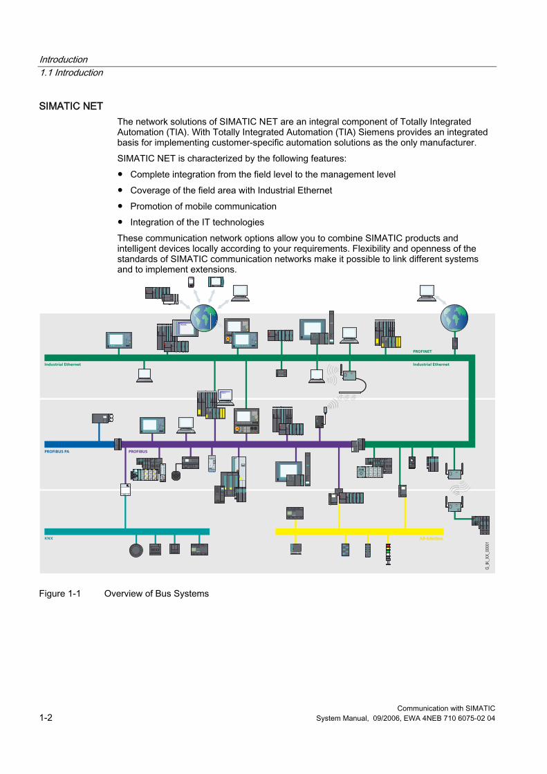
SIMATIC NET The network solutions of SIMATIC NET are an integral component of Totally Integrated Automation (TIA). With Totally Integrated Automation (TIA) Siemens provides an integrated basis for implementing customer-specific automation solutions as the only manufacturer. SIMATIC NET is characterized by the following features: ● Complete integration from the field level to the management level ● Coverage of the field area with Industrial Ethernet ● Promotion of mobile communication ● Integration of the IT technologies These communication network options allow you to combine SIMATIC products and intelligent devices locally according to your requirements. Flexibility and openness of the standards of SIMATIC communication networks make it possible to link different systems and to implement extensions.
Figure 1-1 Overview of Bus Systems
Introduction 1.1 Introduction
Communication with SIMATIC System Manual, 09/2006, EWA 4NEB 710 6075-02 04 1-3
Overview of the Networks This manual deals with the following networks: ● Industrial Ethernet
The industrial network standard for all levels ● PROFINET
The open Industrial Ethernet standard for automation ● PROFIBUS
The international standard for the field area and market leader at the field busses ● AS-Interface
The inexpensive system for linking sensors and actuators as an alternative to cable harnesses
● MPI The integrated interface of the SIMATIC products
● PPI The integrated interface specially for the S7-200
● Point-to-point Communication The serial coupling of two communication partners
● KONNEX (KNX/EIB) The universal bus system for the complete home and building technology

Introduction 1.1 Introduction
Communication with SIMATIC 1-4 System Manual, 09/2006, EWA 4NEB 710 6075-02 04

Communication with SIMATIC System Manual, 09/2006, EWA 4NEB 710 6075-02 04 2-1
PROFINET / Industrial Ethernet 22.1 Introduction
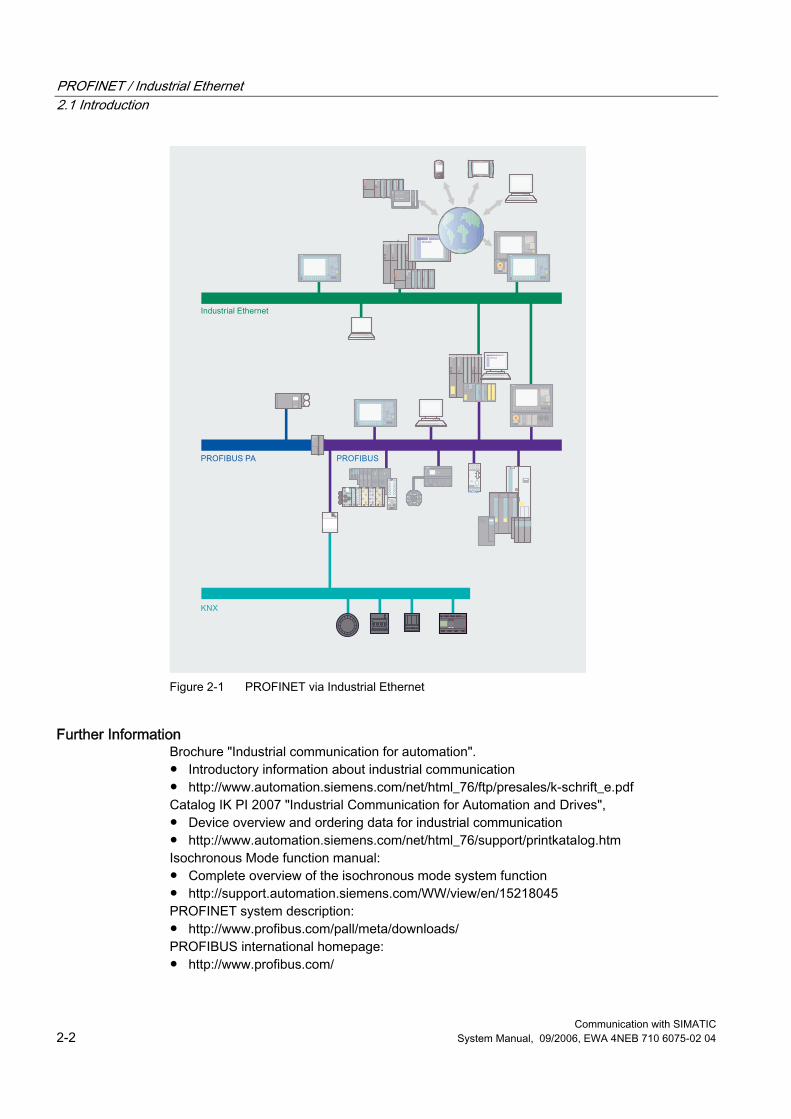
Industrial Ethernet, which is based on the IEEE 802.3, allows you to connect your automation system to your office networks. Industrial Ethernet provides IT services that allow you to access production data from the office environment. PROFINET is an open standard conforming to the IEEE 61158 for industrial automation based on Industrial Ethernet. PROFINET uses the IT standards right down to the field level and supports plant-wide engineering. With PROFINET you can implement automation solutions with a higher performance that require hard realtime, for example in the field of motion control.
PROFINET / Industrial Ethernet 2.1 Introduction
Communication with SIMATIC 2-2 System Manual, 09/2006, EWA 4NEB 710 6075-02 04
Figure 2-1 PROFINET via Industrial Ethernet
Further Information Brochure "Industrial communication for automation". ● Introductory information about industrial communication ● http://www.automation.siemens.com/net/html_76/ftp/presales/k-schrift_e.pdf Catalog IK PI 2007 "Industrial Communication for Automation and Drives", ● Device overview and ordering data for industrial communication ● http://www.automation.siemens.com/net/html_76/support/printkatalog.htm Isochronous Mode function manual: ● Complete overview of the isochronous mode system function ● http://support.automation.siemens.com/WW/view/en/15218045 PROFINET system description: ● http://www.profibus.com/pall/meta/downloads/ PROFIBUS international homepage: ● http://www.profibus.com/
PROFINET / Industrial Ethernet 2.2 Properties
Communication with SIMATIC System Manual, 09/2006, EWA 4NEB 710 6075-02 04 2-3
2.2 Properties
2.2.1 Basic principles
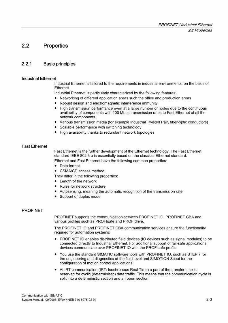
Industrial Ethernet Industrial Ethernet is tailored to the requirements in industrial environments, on the basis of Ethernet. Industrial Ethernet is particularly characterized by the following features: ● Networking of different application areas such the office and production areas ● Robust design and electromagnetic interference immunity ● High transmission performance even at a large number of nodes due to the continuous
availability of components with 100 Mbps transmission rates to Fast Ethernet at all the network components.
● Various transmission media (for example Industrial Twisted Pair, fiber-optic conductors) ● Scalable performance with switching technology ● High availability thanks to redundant network topologies
Fast Ethernet Fast Ethernet is the further development of the Ethernet technology. The Fast Ethernet standard IEEE 802.3 u is essentially based on the classical Ethernet standard. Ethernet and Fast Ethernet have the following common properties: ● Data format ● CSMA/CD access method They differ in the following properties: ● Length of the network ● Rules for network structure ● Autosensing, meaning the automatic recognition of the transmission rate ● Support of duplex mode
PROFINET PROFINET supports the communication services PROFINET IO, PROFINET CBA and various profiles such as PROFIsafe and PROFIdrive. The PROFINET IO and PROFINET CBA communication services ensure the functionality required for automation systems: ● PROFINET IO enables distributed field devices (IO devices such as signal modules) to be
connected directly to Industrial Ethernet. For additional support of fail-safe applications, devices communicate over PROFINET IO with the PROFIsafe profile.
● You use the standard SIMATIC software tools with PROFINET IO, such as STEP 7 for the engineering and diagnostics at the field level and SIMOTION Scout for the configuration of motion control applications.
● At IRT communication (IRT: Isochronous Real Time) a part of the transfer time is reserved for cyclic (deterministic) data traffic. This means that the communication cycle is split into a deterministic section and an open section.
PROFINET / Industrial Ethernet 2.2 Properties
Communication with SIMATIC 2-4 System Manual, 09/2006, EWA 4NEB 710 6075-02 04
● You can route both the IRT and TCP/IP communications over the same network at the same time without their affecting each other.
● By supporting isochronous real-time communications, PROFINET provides the short and deterministic send cycles that are critical for motion control applications.
● PROFINET CBA (Component Based Automation) allows you to implement a modular solution for your distributed automation system. Using the component-based functionality of PROFINET CBA, you structure the automation system into independent modules. The connections between the modules are implemented with the graphics engineering tool SIMATIC iMap. This tool supports you in interconnecting modules up to complete plant and complete systems.
● PROFINET CBA supports cyclic and acyclic communication and is particularly suitable for data transfer between controllers thanks to its send cycles of up to 10 ms.
● PROFIdrive is the functional interface between control systems and drives at PROFINET and at PROFIBUS. PROFIdrive is defined by the PROFIdrive drive profile of the PROFIBUS User Organization (PNO). The PROFIdrive drive profile defines the device behavior and the access procedure to drive data for electrical drives, from simple frequency converters up to high performance servo controllers.
● PROFIsafe is the profile of PROFINET and PROFIBUS for safety-oriented communication. PROFIsafe uses the conventional standard automation of PROFINET and PROFIBUS and is certified for the safety levels up to SIL 3 (Safety Integrated Level) of IEC 61508 as well as Category 4 of EN954-1.
● PROFINET defines requirements on the information security for automation systems and supports the users with possible security solutions specially in the industrial environment.
Further Information Further information about the PROFINET standards and the participating companies can be found on the homepage of the PROFINET User Organization (PNO), under the Internet address http://profibus.de. The PROFINET Security Guideline is available on the PNO homepage, under the Internet address http://profibus.de, in Version 1.0 of March 2005.
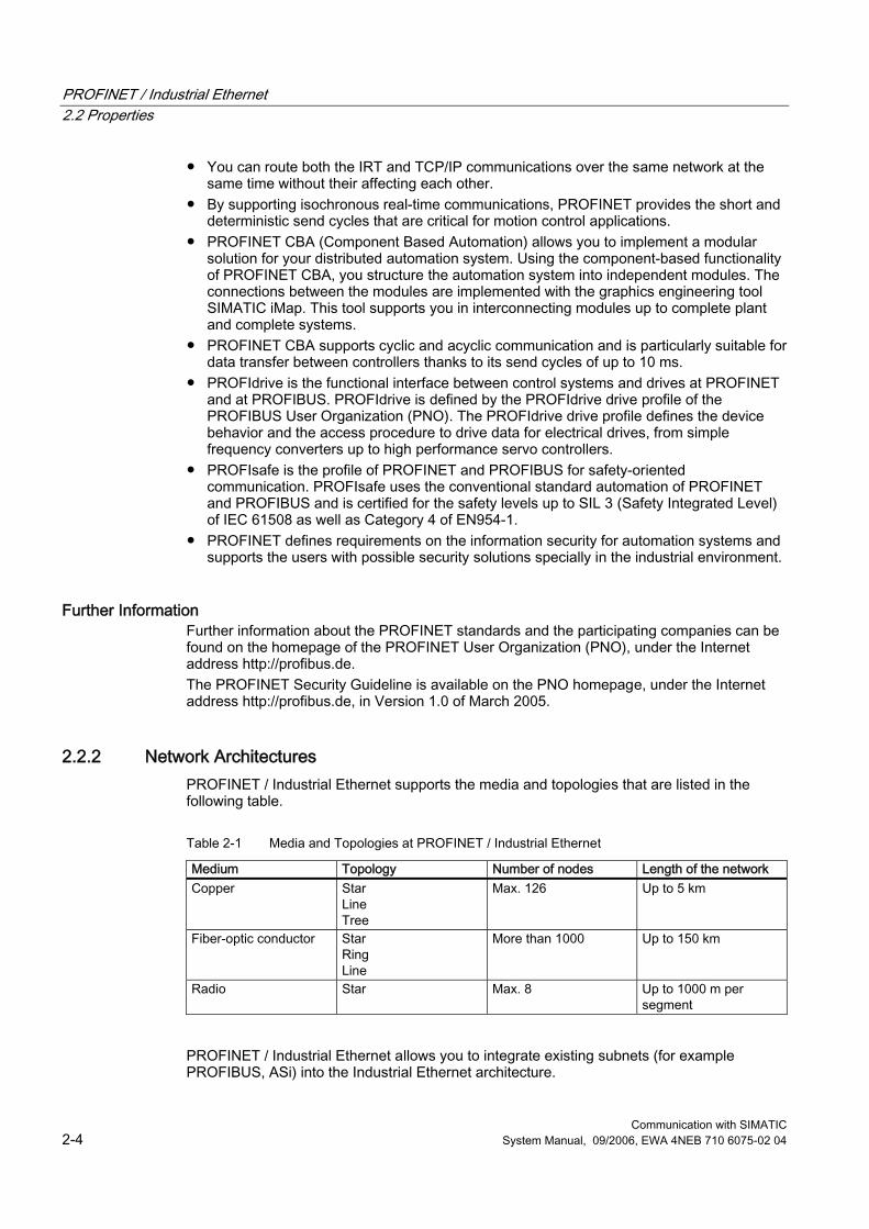
2.2.2 Network Architectures PROFINET / Industrial Ethernet supports the media and topologies that are listed in the following table.
Table 2-1 Media and Topologies at PROFINET / Industrial Ethernet
Medium Topology Number of nodes Length of the network Copper Star
Line Tree
Max. 126 Up to 5 km
Fiber-optic conductor Star Ring Line
More than 1000 Up to 150 km
Radio Star Max. 8 Up to 1000 m per segment
PROFINET / Industrial Ethernet allows you to integrate existing subnets (for example PROFIBUS, ASi) into the Industrial Ethernet architecture.
PROFINET / Industrial Ethernet 2.2 Properties
Communication with SIMATIC System Manual, 09/2006, EWA 4NEB 710 6075-02 04 2-5
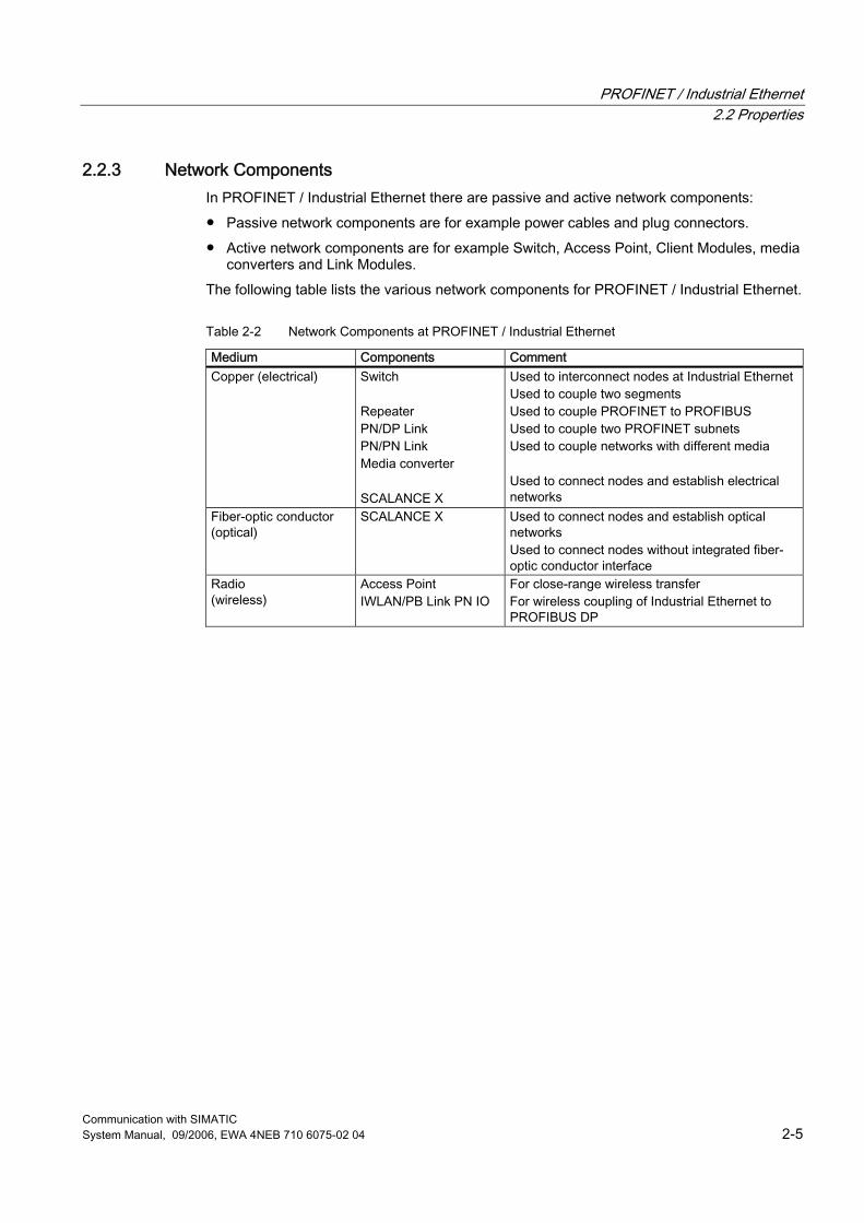
2.2.3 Network Components In PROFINET / Industrial Ethernet there are passive and active network components: ● Passive network components are for example power cables and plug connectors. ● Active network components are for example Switch, Access Point, Client Modules, media
converters and Link Modules. The following table lists the various network components for PROFINET / Industrial Ethernet.
Table 2-2 Network Components at PROFINET / Industrial Ethernet
Medium Components Comment Copper (electrical) Switch
Repeater PN/DP Link PN/PN Link Media converter SCALANCE X
Used to interconnect nodes at Industrial Ethernet Used to couple two segments Used to couple PROFINET to PROFIBUS Used to couple two PROFINET subnets Used to couple networks with different media Used to connect nodes and establish electrical networks
Fiber-optic conductor (optical)
SCALANCE X Used to connect nodes and establish optical networks Used to connect nodes without integrated fiber-optic conductor interface
Radio (wireless)
Access Point IWLAN/PB Link PN IO
For close-range wireless transfer For wireless coupling of Industrial Ethernet to PROFIBUS DP
PROFINET / Industrial Ethernet 2.2 Properties
Communication with SIMATIC 2-6 System Manual, 09/2006, EWA 4NEB 710 6075-02 04
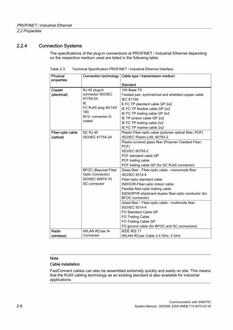
2.2.4 Connection Systems The specifications of the plug-in connections at PROFINET / Industrial Ethernet depending on the respective medium used are listed in the following table.
Table 2-3 Technical Specification PROFINET / Industrial Ethernet Interface
Physical properties
Connection technology Cable type / transmission medium Standard
Copper (electrical)
RJ 45 plug-in connector ISO/IEC 61754-24 IE FC RJ45 plug 90/145/180 M12- connector D-coded
100 Base TX Twisted pair, symmetrical and shielded copper cable IEC 61158 E FC TP standard cable GP 2x2 IE FC TP flexible cable GP 2x2 IE FC TP trailing cable GP 2x2 IE TP torsion cable GP 2x2 IE FC TP trailing cable 2x2 IE FC TP marine cable 2x2 Plastic Fiber-optic cable (polymer optical fiber, POF) ISO/IEC Plastic-LWL 60793-2
SC RJ 45 ISO/IEC 61754-24
Plastic-covered glass fiber (Polymer Cladded Fiber, PCF) ISO/IEC 60793-2 PCF standard cable GP PCF trailing cable PCF trailing cable GP (for SC RJ45 connector) Glass fiber - Fiber-optic cable - monomode fiber ISO/IEC 9314-4 Fiber-optic standard cable INDOOR-Fiber-optic indoor cable Flexible fiber-optic trailing cable SIENOPYR shipboard-duplex fiber-optic conductor (for BFOC connector)
Fiber-optic cable (optical)
BFOC (Bayonet Fiber Optic Connector) ISO/IEC 60874-10 SC connector
Glass fiber - Fiber-optic cable - multimode fiber ISO/IEC 9314-4 FO Standard Cable GP FO Trailing Cable FO Trailing Cable GP FO ground cable (for BFOC and SC connectors)
Radio (wireless)
IWLAN RCoax N-Connector
IEEE 802.11 IWLAN RCoax Cable 2,4 GHz, 5 GHz
Note Cable installation FastConnect cables can also be assembled extremely quickly and easily on site. This means that the RJ45 cabling technology as an existing standard is also available for industrial applications.
PROFINET / Industrial Ethernet 2.2 Properties
Communication with SIMATIC System Manual, 09/2006, EWA 4NEB 710 6075-02 04 2-7
2.2.5 High-Availability
Overview Fault-tolerant systems are designed to reduce production downtime. Availability can be enhanced, for example, by means of component redundancy. Communication systems are thus extended to automation systems. Redundant systems in industrial Ethernet are characterized by the multiple (redundant) presence of important automation components. When a redundant component fails, processing of the program is not interrupted. Redundancy is achieved by duplicating the part components such as CPU, network, CP, etc.. Monitoring and synchronization mechanisms ensure that if the active redundant connection path fails, the previously passive (redundant) connection path takes over the communication automatically. The connection itself remains established.
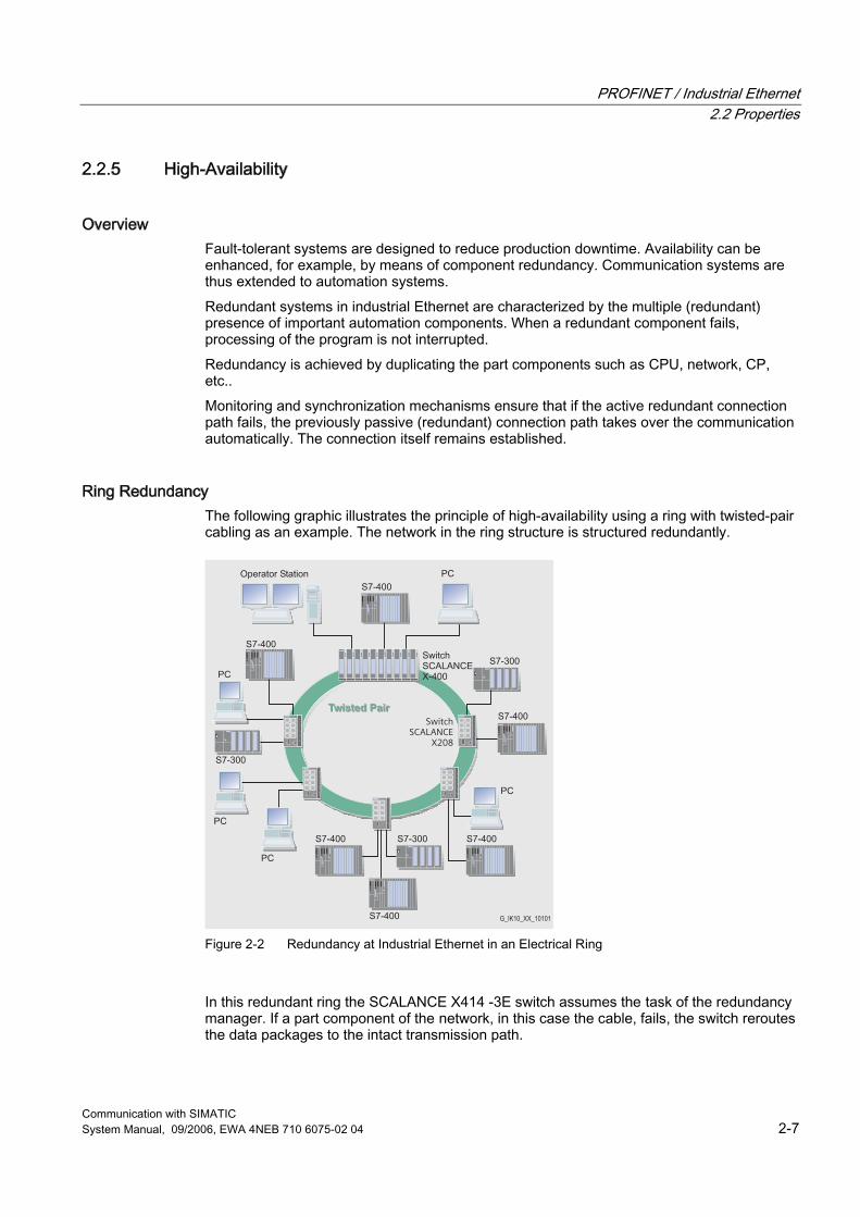
Ring Redundancy The following graphic illustrates the principle of high-availability using a ring with twisted-pair cabling as an example. The network in the ring structure is structured redundantly.
Figure 2-2 Redundancy at Industrial Ethernet in an Electrical Ring
In this redundant ring the SCALANCE X414 -3E switch assumes the task of the redundancy manager. If a part component of the network, in this case the cable, fails, the switch reroutes the data packages to the intact transmission path.
PROFINET / Industrial Ethernet 2.3 Technology
Communication with SIMATIC 2-8 System Manual, 09/2006, EWA 4NEB 710 6075-02 04
2.3 Technology
2.3.1 Transmission Methods
Overview Industrial Ethernet uses the protocol family TCP/IP or UDP/IP for data transfer. These are essentially defined in the following RFCs (RFC: Request For Comment): ● RFC 768: UDP (User Datagram Protocol) ● RFC 791: IP (Internet Protocol) ● RFC 792: ICMP (Internet Control Message Protocol) ● RFC 793: TCP (Transmission Control Protocol) However, Industrial Ethernet is unsuitable for cyclic data exchange due to its telegram overhead. An optimized Layer-2 protocol conforming to IEEE 802.3 that makes real-time communication on the basis of Industrial Ethernet possible is therefore used. Data transfer by means of PROFINET takes place through Industrial Ethernet. The following transmission types are supported: ● Cyclic transfer of user data (for example process values, etc.). ● Acyclic transfer of engineering data and time-critical data. ● PROFINET CBA uses automatic retransmission and additional checking mechanisms
(parity bit per character and checksum) to provide a high degree of data integrity and accuracy.
Real-time communication (Real-Time, RT) Real-time means that a system processes external events within a defined time. Determinism means that a system responds in a predictable (deterministic) manner. Both requirements are important for industrial networks. PROFINET fulfills these requirements with the following transfer characteristics: ● Transfer of time-critical data takes place at guaranteed time intervals.
To achieve this, PROFINET provides an optimized communication channel for real-time communication.
● The time of transfer can be accurately determined.(forecast). ● Problem-free communication using other standard protocols is guaranteed within the
same network.
PROFINET / Industrial Ethernet 2.3 Technology
Communication with SIMATIC System Manual, 09/2006, EWA 4NEB 710 6075-02 04 2-9
Isochronous Real-Time Communication, IRT At PROFINET with IRT the communication cycle is subdivided into different, time-specific channels for this purpose. The first channel is used for isochronous real-time communication (IRT), followed by real-time communication (RT) and standard TCP/IP communication. In this way, both types of data data transfer exist together without interfering with each other. When this transmission method is implemented in ERTEC-ASICs (Enhanced Real-Time Ethernet Controller), cycle times of 0.25 ms and jitter accuracy below 1 µs are achieved.
Applications for IRT IRT is used in areas with particularly stringent requirements for response times that cannot be exceeded. This is the case, for example, for motion control applications, which require response and update times in the range of a few milliseconds.
IRT Communication / Real-Time and TCP/IP Communication Alongside IRT communication for which a bandwidth is reserved within the update time, RT and TCP / IP communications are also permitted within the update time. In RT communication the cyclic data are transferred between the IO controller and IO device, however, without the "best possible synchronicity". Unsynchronized IO devices automatically exchange data using RT communication.
2.3.2 Access Methods
Collision Recognition with CSMA/CD Ethernet uses the bus access method CSMA/CD. This abbreviation stands for Carrier Sense Multiple Access with Collision Detection. In this method a node that wants to send listens to the common bus line (Carrier Sense) and sends if it is not occupied. If the bus line is occupied by another node, the node that wants to send postpones its wish to send and tries to transfer again later on (Multiple Access). In order to recognize collisions, the nodes receive the signals while they are sending. If the sent and received data differ, a collision has occurred, and the transfer is stopped and restarted later at a moment that is randomly controlled. In order to implement networks with a larger extension, switches with full duplex function can be used. If switching technology and full duplex mode are used throughout, collisions cannot occur.
Switching Mechanisms PROFINET uses switched Ethernet as the access method. This consists of a point-to-point connection where every device is connected directly with one (and only one) other device. A switch enables communication to take place simultaneously in both directions (sending and receiving). This provides a network capacity of 200 Mbps, or twice the bandwidth of Fast Ethernet (100 Mbps). Due to the use of switching technology that is stipulated for PROFINET, data transfer is collision-free at PROFINET. Switches in SIMATIC fulfill the real-time properties by means of two mechanisms at PROFINET: "Cut through" and "Store and Forward". The advantage of the switching mechanisms: Nodes or networks that do not need the telegram are not stressed with data that are not relevant to them. The resulting free network capacities can be used by further devices. With switching technology it is possible, in contrast to a conventional solution, to communicate in parallel in different network sections, thus increasing the effective bandwidth.
PROFINET / Industrial Ethernet 2.3 Technology
Communication with SIMATIC 2-10 System Manual, 09/2006, EWA 4NEB 710 6075-02 04
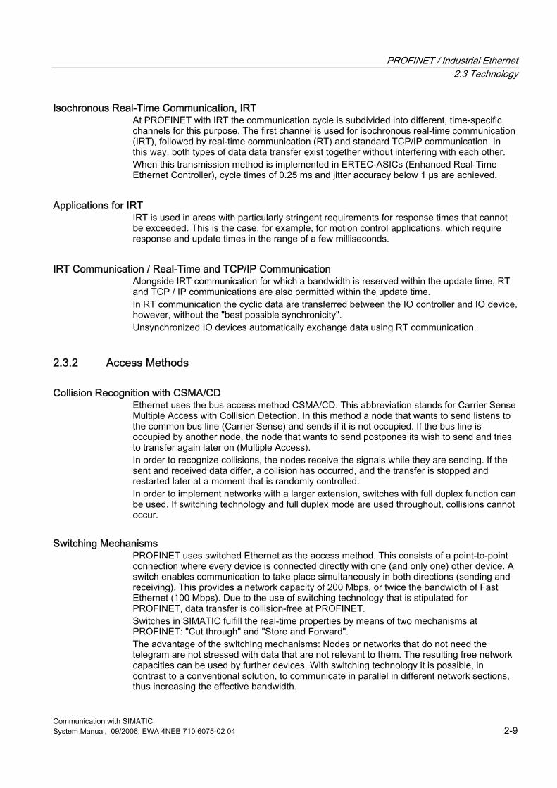
Store and Forward In the Store and Forward process the switch stores the telegrams and rows them into a queue. The telegrams are then forwarded selectively to the specific port that can access the addressed node (Store and Forward).
Figure 2-3 Store and Forward at Industrial Ethernet
Cut Through In the Cut Through process not the entire data package is stored temporarily in a buffer, but is passed directly onto the target port as soon as the first 6 bytes (target address) have been read. The times required by the data package to pass the switch are then minimal. The data are only stored temporarily in accordance with the Store and Forward process when the section between the target part and the port of the next switch is occupied.
PROFINET / Industrial Ethernet 2.4 Information Security in the Automation
Communication with SIMATIC System Manual, 09/2006, EWA 4NEB 710 6075-02 04 2-11
2.4 Information Security in the Automation
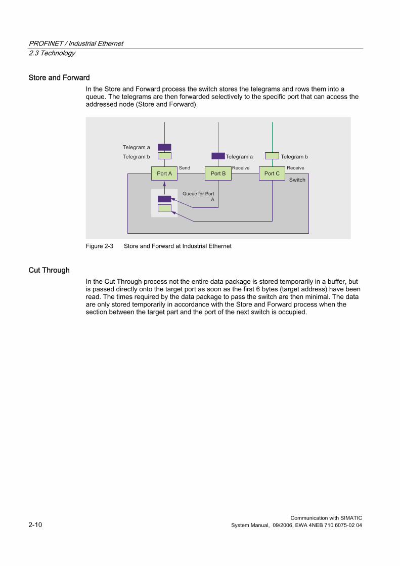
Overview Modern automation technology is based on communication and the trend toward increased networking of individual manufacturing cells. It is becoming more and more important to integrate all the manufacturing components into a uniform network that merges with the office network and the corporate Intranet. There is also a requirement for remote access for servicing, the increasing use of IT mechanisms such as Web servers and e-mail with programmable controllers as well as the use of wireless LANs. In this manner, industrial communication interacts more and more with the IT environment and is now subjected to the same dangers that are well-known from the office and IT environment, such as hackers, viruses, worms and Trojans. The current security concepts are tailored to the office world and require constant administration and specialist knowledge. They are not usually conversant with the special protocol landscape of industrial communication and are not designed to withstand the harsh environmental conditions. With its security concept, Siemens offers a safety solution specially designed for industrial automation engineering that satisfies the specific requirements of this application environment.
Figure 2-4 Secure Communication - Overview
PROFINET / Industrial Ethernet 2.4 Information Security in the Automation
Communication with SIMATIC 2-12 System Manual, 09/2006, EWA 4NEB 710 6075-02 04
Advantages of industrial security concept ● Protection from espionage and data manipulation ● Protection against overloading of the communication system ● Protection against mutual interference ● Protection against addressing mistakes ● User-friendly and simple configuration and administration without specialist knowledge of
IT security ● No changes or modification of the existing network structure are necessary ● No changes or modification of the existing applications or network stations are necessary ● Rugged, industry-compatible design
Features From the particular requirements on the communication in the industrial environment (e.g. communication in real-time) there brings about additional requirements on the security for the industrial application: ● Repercussion protection for the automated cells, meaning that network topologies do not
have to be changed and network nodes do not have to be reconfigured. ● Protection of network segments ● Protection against faulty access ● Scalability of the security functionality ● No influence on the network structure
Definition of IT Security Generic term for all measures that protect against ● The loss of confidentiality through unauthorized access to data ● The loss of integrity through manipulation of data ● The loss of availability through the destruction of data
Aims of Industrial Security ● Trouble-free operation and ensured availability of industrial plants and production
processes ● Protection of industrial communication against espionage and manipulation ● Protection of industrial automation systems and components against unauthorized
access and data loss ● Practicable and cost-effective concept for securing existing systems and devices without
own security functions ● Utilization of existing, open, tried and tested IT security standards ● Security concept optimized and adapted for automation technology
PROFINET / Industrial Ethernet 2.4 Information Security in the Automation
Communication with SIMATIC System Manual, 09/2006, EWA 4NEB 710 6075-02 04 2-13
Precautions The most significant precautions against manipulation and loss of data security in the industrial environment are: ● Filtering and inspection of the data traffic by means of Virtual Private Networks (VPN)
A virtual private network is used to exchange private data in an official network (e.g. Internet). The most common VPN technology is IPsec. IPsec is a collection of protocols for ensuring information security that use the IP protocol on the network layer.
● Segmenting in the protected automation cells This concept has the aim of protecting the network nodes by means of security modules. A group of protected devices forms a protected automation cell. Only security modules of the same type or devices they are protecting can exchange data amongst each other.
● Authentication (identification) of the nodes By means of authentication procedures the security modules identify each other via a safe (encrypted) channel. It is therefore impossible for unauthorized parties to access a protected segment.
● Encrypting the data traffic The confidentiality of data is ensured by means of encrypting the data traffic. For this purpose each security module obtains a VPN certificate in which, among others, includes the code.
SCALANCE S Security Modules SCALANCE S security modules offer a scaleable security functionality. ● Firewall for protecting the programmable controllers from unauthorized access regardless
of the size of the network to be protected. The firewall can be used as an alternative or to supplement VPN with flexible access control. The firewall filters data packets and disables or enables communication links in accordance with the filter list (packet filter firewall). Both incoming and outgoing communication can be filtered, IP and MAC addresses, as well as communication protocols (ports).
● Supplementary or alternative VPN (Virtual Private Network) for reliable authentication of the communication partners and encryption of the transmitted data
Configuration Configuring is simple to carry out even without special IT knowledge. Only the Security Modules or SOFTNET Security Clients that have to communicate with each other securely have to be created and configured. The entire configuration can be stored on the optional removable medium C-PLUG (not included in the scope of delivery). In case of a fault the Security Module can then be replaced rapidly and without a programming device.
PROFINET / Industrial Ethernet 2.5 Services
Communication with SIMATIC 2-14 System Manual, 09/2006, EWA 4NEB 710 6075-02 04
2.5 Services
2.5.1 Standard Communication Services - Overview SIMATIC integrates IT functions such as e-mail and Web technology into the information technology through Industrial Ethernet. In the office environment, e-mail and Web browsers are widely used communication techniques. Ethernet is used as the main communication path, in addition to telephone cables and the Internet. These communication media and paths are also available to SIMATIC as a result of the TCP/IP protocol. The following IT services are supported by the SIMATIC device family: ● FTP communication (File Transfer Protocol) for program-driven data exchange between
computers having different operating systems ● E-mail via SMTP (Simple Mail Transfer Protocol) ● HTML process control / access to Web browsers via HTTP (Hyper Text Transfer
Protocol) In the case of CPs with IT function, you use the supplied functions and HTML pages to query important system data over a Web browser. The HTML process control can be used for communication between a PC station and an S7-300 or S7-400.
PROFINET / Industrial Ethernet 2.5 Services
Communication with SIMATIC System Manual, 09/2006, EWA 4NEB 710 6075-02 04 2-15
2.5.2 FTP Services
Overview File transfer protocol functions (FTP) enable an IT-CP or Advanced CP to provide a powerful means of transmitting files to and from the following S7 devices: ● Programming device/PC and S7-300/400 ● Between several S7-200/300/400 devices ● Between S7 and process control computers or MES level
Properties The IT-CP or Advance CP can be operated both as an FTP server and an FTP client. ● FTP server
This function enables you to use FTP commands to transfer data in the form of files to or from data blocks of an S7 station. For transmission of data via FTP, you create data blocks (File DBs) in the CPU of your S7 station. When an FTP command is issued, the IT-CP/Adv-CP as FTP server uses a file assignment table (file_db.txt) to determine how the data blocks used for the file transfer in the S7 station are to be mapped to files. The information in the file assignment table enables you to reference data blocks in one or more (up to 4) CPUs in an S7 station.
● FTP client You create data blocks (file DBs) in the CPU of your S7 station for purposes of transferring data via FTP. Using special FCs, the user program issues FTP requests, which are then executed by the IT-CP or Advanced CP as an FTP client. The transmission takes place over FTP connections. FTP connections are special TCP connections that you have to configure in STEP 7 / NetPro. The request contains an additional target parameter specifying the IP address of the FTP server, the file storage location on the FTP server, and the file name, as well as access information.
Integration in STEP 7 To manage an FTP request sequence between the S7 station as FTP client and an FTP server, the IT-CP or Advanced CP must set up a connection to the S7-CPU. An FTP connection is set up as follows: ● Using the connection configuration in STEP 7 (standard application) ● Using the user program with FB CP_CONFIG and configuration data block.
In some applications it is advantageous to program the setup of the communication connections using special applications and not using the STEP 7 configuration interface.
Further Information For more information on IT services, refer to the manual Information Technology with CP 343–IT and CP 443–IT and CP 243-IT and Information Technology at SIMATIC S7 with CPs for S7-300 and S7-400.
PROFINET / Industrial Ethernet 2.5 Services
Communication with SIMATIC 2-16 System Manual, 09/2006, EWA 4NEB 710 6075-02 04
2.5.3 E-Mail Services
Overview The automation system can use the e-mail function of the IT-CP or Advanced CP to send process- or time-dependent communications containing process information.
Features Based on the usual features of e-mail, it is possible to send messages with or without attachments. The form of delivery is selected depending on the amount of data and the properties of the receiving device. E-mail with attachments may be necessary, for example, for conveying binary-coded information from a controller for evaluation purposes. ● The IT-CP or Advanced-CP works as an e-mail client. It supports the SMTP service
(Simple Mail Transfer Protocol). ● E-mails can be sent from the automation system, but not received. To send e-mail in the
user program of the S7-300 or S7-400 CPU, you poll the SEND/RECEIVE interface (FC AG_SEND / AG_LSEND).
E-mails are sent via the SMTP service. Encoding e-mails to increase transmission reliability is not possible.
Integration in STEP 7 To send e-mails, an e-mail connection must always be set up for each IT-CP or Advanced-CP. The e-mail connection defines the mail sever to be used for delivering all e-mails sent by the IT-CP or Advanced-CP. The complete e-mail, including the address information and the message itself, is generated in a random data block. As soon as you have configured the IT-CP or Advanced-CP with HW Config in the station, there are two options for establishing an e-mail connection. ● Using the connection configuration in STEP 7 (standard application) ● Using the user program with FB CP_CONFIG and configuration data block.
Further Information For more information on IT services, refer to the Information Technology with CP 343-1 IT and CP 443-1 IT and CP243-1 IT manual.
PROFINET / Industrial Ethernet 2.5 Services
Communication with SIMATIC System Manual, 09/2006, EWA 4NEB 710 6075-02 04 2-17
2.5.4 SNMP Services
Overview SNMP (Simple Network Management Protocol) is a standardized open protocol for network management in Ethernet networks. Network management includes all functions that are suitable for monitoring, controlling, and parameterizing network nodes. Network management (e.g., error logging) protects a network with SNMP-capable network nodes from failure and ensures high network quality and efficiency. The network management products such as SINEMA E and the SNMP-OPC Server of Siemens support you in essential tasks related to the planning, control and monitoring of networks in an industrial environment.
Features SNMP is defined in RFC 1065, RFC 1066, and RFC 1067. An expansion of the protocol to include safety functions for read/write access is described in RFC 2571 (Request for Comments). The SNMP network management protocol makes use of the wireless UDP transport protocol. The SNMP Manager monitors the network nodes, and the SNMP agents collect the various network-specific information in the individual network nodes and places it in a structured form in the MIB - Management Information Base. The MIB information is polled by the management station and, if appropriate, visualized. The nodes, however, are also able to report certain statuses to the network management stations via so-called traps. With SNMP it is not only possible to monitor the nodes, but operations and instructions for controlling the devices are also possible. This includes, for example, for the activation or deactivation of a port at a network component. The communication between the agent and the network management station is executed in the background and only places a minor load on the network. To integrate additional SNMP devices that have files in the MIB, you can use STEP 7 or NCM PC. Configuration of the OPC server is integrated in the STEP 7 Hardware Configuration application. Already configured S7 modules from the STEP 7 project can be transferred directly. As an alternative to STEP 7, the NCM PC (included on the SIMATIC NET CD) can also be used to perform the configuration. Fast Online Configuration using "Autodiscovery" In STEP 7 V5.3 SP3 and higher, all Ethernet devices can be detected by means of their IP address and/or the SNMP protocol (SNMP V1) and transferred to the configuration. The SIMATIC NET SNMP OPC server also provides detection of PROFINET devices using the DCP protocol.
Integration in STEP 7 The SNMP OPC Server is configured with STEP 7/NCM PC. STEP 7/NCM PC is used to specify to the SNMP OPC Server which stations (entry of the station IP address) it is to monitor. In addition, STEP 7/NCM PC supports you in selecting a profile when monitoring the data. The profile describes a readable/writeable object in an SNMP node and is a subset of an MIB. The term MIB II describes the minimum scope of such objects that is understood by every SNMP device. If device-specific data have to be read/written, a "private" MIB of the manufacturer has to be read in and a new profile (function of the MIB compiler in STEP 7/NCM PC) created. SIEMENS AG makes its MIBs as well as ready-to-use profiles for the SNMP OPC Server available on the Support pages (see Additional Information).
PROFINET / Industrial Ethernet 2.5 Services
Communication with SIMATIC 2-18 System Manual, 09/2006, EWA 4NEB 710 6075-02 04
Use of SNMP in SIMATIC NET SNMP-capable devices of the SIMATIC NET family can be monitored and operated via a conventional standard Internet browser. For Industrial Ethernet applications, the SIMATIC NET switches also provide information on the network load based on SNMP.
Diagnostics with SNMP OPC Server in SIMATIC NET The SNMP OPC server software provides diagnostic and parameter assignment functions for all SNMP devices. The OPC server uses the SNMP protocol to perform data exchange with SNMP devices. All information can be integrated in OPC-compatible systems, such as the WinCC HMI system. This is a possibility of including SNMP data (for example of a switch) in an OPC-capable application (for example WinCC, PCS7 or other HMI/SCADA systems) . This enables process and network diagnostics to be combined in the HMI system.
Further Information For additional information on the SNMP OPC server, refer to the PCS 7 Network Diagnostics with the SNMP OPC Server function manual. The RFCs described in this manual can be found at: http://www.ietf.org/rfc or http://www.rfc-editor.org MIB files can be found at the Internet address: http://support.automation.siemens.com/WW/view/en/22015045 Further Information about the MIBs and SNMP OPC Server is available at the Internet address: http://www.siemens.com/snmp-opc-server
PROFINET / Industrial Ethernet 2.5 Services
Communication with SIMATIC System Manual, 09/2006, EWA 4NEB 710 6075-02 04 2-19
2.5.5 OPC Services
Overview OPC (OLE for Process Control) allows Windows applications to access process data, making it easy to combine devices and applications produced by different manufacturers.
Features Not only does OPC provide an open, vendor-independent interface, but the easy-to-use client-server configuration provides standardized data exchange between the components of an automation solution (such as a PLC), field devices, and PC-based applications (such as HMI or office applications).
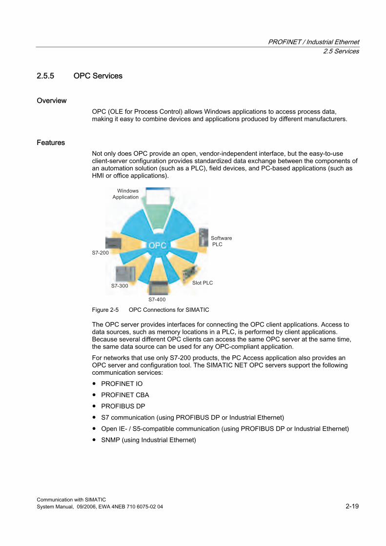
Figure 2-5 OPC Connections for SIMATIC
The OPC server provides interfaces for connecting the OPC client applications. Access to data sources, such as memory locations in a PLC, is performed by client applications. Because several different OPC clients can access the same OPC server at the same time, the same data source can be used for any OPC-compliant application. For networks that use only S7-200 products, the PC Access application also provides an OPC server and configuration tool. The SIMATIC NET OPC servers support the following communication services: ● PROFINET IO ● PROFINET CBA ● PROFIBUS DP ● S7 communication (using PROFIBUS DP or Industrial Ethernet) ● Open IE- / S5-compatible communication (using PROFIBUS DP or Industrial Ethernet) ● SNMP (using Industrial Ethernet)
PROFINET / Industrial Ethernet 2.5 Services
Communication with SIMATIC 2-20 System Manual, 09/2006, EWA 4NEB 710 6075-02 04
Integration in STEP 7 In addition to providing OPC servers, SIMATIC NET also provides the following applications for configuring and testing OPC connections: ● Advanced PC Configuration (APC) ● OPC Scout You use these tools to connect SIMATIC S7 products to other OPC-compliant applications.
2.5.6 PROFINET IO Services
Overview PROFINET IO is a communication standard for the implementation of modular, distributed applications. With PROFINET IO, distributed field devices (IO-Devices) can be directly connected to Industrial Ethernet.
Features PROFINET IO communication provides three performance levels: ● Non-Real-Time (NRT) uses the TCP/UDP/IP channel to transfer parameterization and
non-time-critical data with a typical cycle time of approximately 100 ms. ● Real-Time (RT) provides the transfer of time-critical process data by prioritizing and
optimizing the communication stacks with a typical update cycle time of 1 ms to 10 ms. ● Isochronous Real-Time (IRT) provides isochronous execution cycles to ensure that the
information is transmitted at consistently equidistant time intervals. IRT delivers isochronous data transmission with very short update cycles (from 250 microseconds to 1 ms) and very little jitter.
PROFINET offers the following further advantages: ● PROFINET IO provides the same device model as PROFIBUS. ● In PROFINET IO, you configure the devices with the same engineering system (for
example STEP 7). The properties of a PROFINET device are described in a GSD file (General Station Description) that contains all the information required for configuration and communication.
● During configuration with STEP 7, these field devices are assigned to an IO-Controller. Existing PROFIBUS modules or devices can continue to be used with PROFINET-capable interfaces or links.
● A proxy is the connecting element between PROFINET and any lower-level fieldbus. For example, the PROFINET IO IE/PB Link allows a PROFINET IO controller to communicate with a PROFIBUS DP slave device.
PROFINET / Industrial Ethernet 2.5 Services
Communication with SIMATIC System Manual, 09/2006, EWA 4NEB 710 6075-02 04 2-21
2.5.7 PROFINET CBA Services
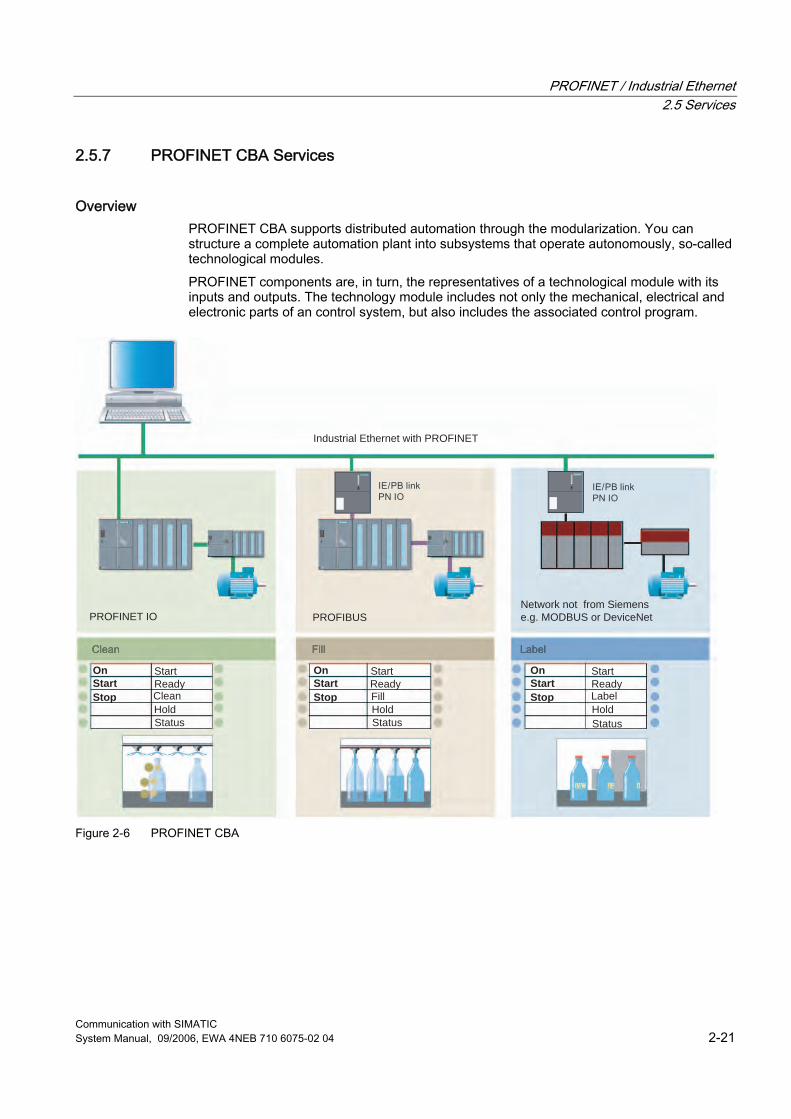
Overview PROFINET CBA supports distributed automation through the modularization. You can structure a complete automation plant into subsystems that operate autonomously, so-called technological modules. PROFINET components are, in turn, the representatives of a technological module with its inputs and outputs. The technology module includes not only the mechanical, electrical and electronic parts of an control system, but also includes the associated control program.
Industrial Ethernet with PROFINET
PROFINET IO PROFIBUS
OnStartStop
OnStartStop
OnStartStop
Network not from Siemense.g. MODBUS or DeviceNet
StartStart StartReadyReadyReadyLabelHoldHoldHoldStatusStatusStatus
Fill Clean
Figure 2-6 PROFINET CBA
PROFINET / Industrial Ethernet 2.5 Services
Communication with SIMATIC 2-22 System Manual, 09/2006, EWA 4NEB 710 6075-02 04
Features PROFINET CBA defines the engineering model (design and construction of the PROFINET components) and the communication between components. A PROFINET component incorporates all the hardware configuration data, the module parameters, and the associated user program. You can use PROFINET IO to integrate field devices within a PROFINET CBA component. By using proxy devices on PROFIBUS, you can also use PROFINET CBA to interconnect all the existing subnets with their controllers and field devices (such as PROFIBUS DP) to form a larger automation system. ● The PROFINET components are accessible by means of uniformly defined interfaces.
These components can be interconnected in any way to allow configuration of the process.
● The open-engineering interface enables graphical configuration of PROFINET components from different manufacturers.
Integration in STEP 7 and SIMATIC iMap ● You use STEP 7 to create reusable modules, which include the definition of the interfaces
for exchanging data with other modules. ● The components are created in the PROFINET Component Description (PCD) and stored
in XML format in the general station description (GSD). ● You use SIMATIC iMap to configure the complete system by graphically linking the
individual components. SIMATIC iMap also allows you to configure simple diagnostics for the system.
PROFINET / Industrial Ethernet 2.5 Services
Communication with SIMATIC System Manual, 09/2006, EWA 4NEB 710 6075-02 04 2-23
2.5.8 PROFIdrive
Overview PROFIdrive is used to include drives in automation solutions - from simple frequency converters to highly dynamic servo controller. To this purpose PROFIdrive defines the device behavior and the methods for accessing drive data at PROFINET.
Features In order to accomplish the various tasks that modern drives must perform, PROFIdrive defines six application classes: ● Class 1 defines a standard drive that is controlled via a main setpoint, e.g., the speed
setpoint. ● Class 2 defines a standard drive with technology function. The process is divided into
subprocesses for this class. Drive tasks are issued to the drive device, requiring direct data exchange between the individual drives.
● Class 3 defines a positioning drive that includes a position controller. The positioning requests are started and transferred via PROFINET.
● Classes 4 and 5 define the central motion control that enables coordinated motion sequences among multiple drives. PROFINET is used to close the position control loop and to synchronize the clock cycles.
● Class 6 includes distributed automation in clocked processes and with electronic shafts. This allows applications such as "electrical gearing" or "cam disk" to be implemented.
PROFIdrive defines the mechanism of accessing parameters and a subset of manufacturer-specific profile parameters. Access to the other parameters is carried out acyclically through a special channel. PROFIdrive is specified in "PROFIdrive Profile – Drive Technology V3".
Integration in STEP 7 Drives are configured with the STEP 7 Hardware Configuration application.
Further Information Further information about the topic of PROFIdrive technology is available at the Internet address http://www.profibus.com/pall/meta/downloads/article/00352/
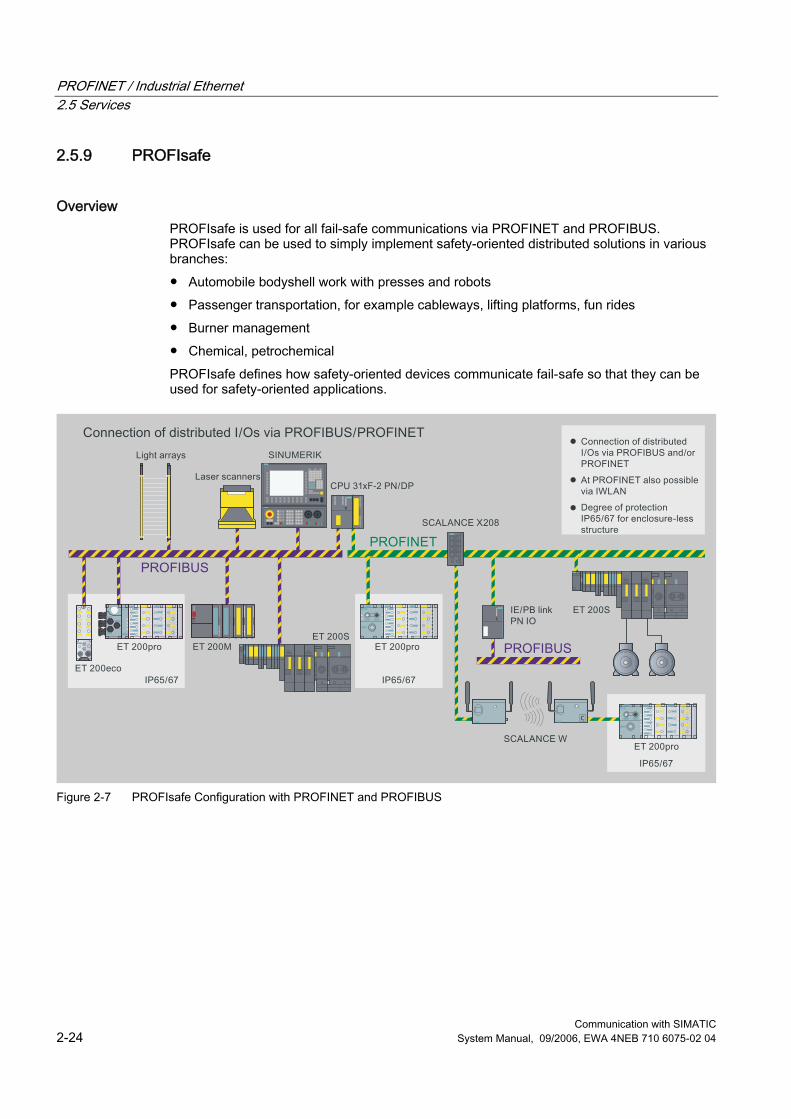
PROFINET / Industrial Ethernet 2.5 Services
Communication with SIMATIC 2-24 System Manual, 09/2006, EWA 4NEB 710 6075-02 04
2.5.9 PROFIsafe
Overview PROFIsafe is used for all fail-safe communications via PROFINET and PROFIBUS. PROFIsafe can be used to simply implement safety-oriented distributed solutions in various branches: ● Automobile bodyshell work with presses and robots ● Passenger transportation, for example cableways, lifting platforms, fun rides ● Burner management ● Chemical, petrochemical PROFIsafe defines how safety-oriented devices communicate fail-safe so that they can be used for safety-oriented applications.
Figure 2-7 PROFIsafe Configuration with PROFINET and PROFIBUS
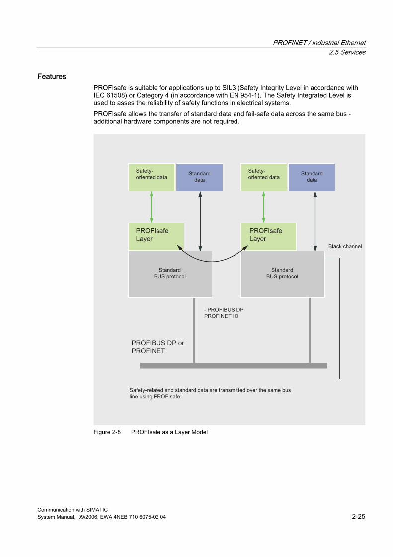
PROFINET / Industrial Ethernet 2.5 Services
Communication with SIMATIC System Manual, 09/2006, EWA 4NEB 710 6075-02 04 2-25
Features PROFIsafe is suitable for applications up to SIL3 (Safety Integrity Level in accordance with IEC 61508) or Category 4 (in accordance with EN 954-1). The Safety Integrated Level is used to asses the reliability of safety functions in electrical systems. PROFIsafe allows the transfer of standard data and fail-safe data across the same bus - additional hardware components are not required.
Figure 2-8 PROFIsafe as a Layer Model
PROFINET / Industrial Ethernet 2.5 Services
Communication with SIMATIC 2-26 System Manual, 09/2006, EWA 4NEB 710 6075-02 04
PROFIsafe is a software solution that is implemented as an additional layer (PROFIsafe Layer) in the devices (for example CPU operating system). The safety data are packed in the telegram as a supplement to the standard data, thus forming the PROFIsafe telegram. PROFIsafe presents two alternative implementations: ● Solution with a bus line and a combined standard and safety-related controller ● Solution with separate transmission lines and separate controllers for standard and
safety-oriented automation PROFIsafe uses the following measures to ensure the data integrity of fail-safe transmissions: ● Sequential numbering of the safety telegrams. ● Time monitoring for telegrams and acknowledgement ● Identification between transmitter and receiver using a password ● Additional data security (Cyclic Redundancy Check) PROFIsafe is specified in "PROFIsafe, Profile for Safety Technology".
Integration in STEP 7 With PROFIsafe, the fail-safe blocks in your user program are marked in yellow to correspond with the yellow that designates the physical fail-safe I/O modules.
Further Information Further information about the topic of fail-safety is available at the Internet address http://www.profibus.com/pb/profibus/safety/
2.5.10 TCP Services
Overview The TCP/IP service facilitates communication to any communication partner (for example, PC or non-Siemens system) that supports sending and receiving data in accordance with RFC 793 and RFC 1323 for TCP and RFC 791 for IP.
Features Contiguous data blocks (maximum of 8 Kbytes) can be transmitted from one Ethernet node to another. Receipt of data is acknowledged by the communication partner. This is indicated in the appropriate block. The TCP service ensures data transfer and thus data integrity by means of two mechanisms: ● Repeated sending of the data in case of transmission errors ● The receiver checks the integrity of the transferred data by means of a cyclic algorithm
(CRC) and acknowledges receipt of the data.
PROFINET / Industrial Ethernet 2.5 Services
Communication with SIMATIC System Manual, 09/2006, EWA 4NEB 710 6075-02 04 2-27
Integration in STEP 7 The PROFINET IO CPUs with integrated PROFINET interface provide integrated function blocks (FBs) for TCP/IP communication: ● FB63 (TSEND) ● FB64 (TRCV) ● FB65 (TCON) ● UDT65 (TCON_PAR) ● FB66 (TDISCON) In SIMATIC S7, the ISO-on-TCP services are used for communication with the blocks AG_SEND/AG_RECV via Industrial Ethernet. In addition, the FETCH/WRITE services constitute an interface through which a SIMATIC S5 or non-Siemens device can have direct access to the system memory of the SIMATIC S7 controller. The AG_LOCK and AG_UNLOCK blocks can be used to coordinate FETCH/WRITE access by the user program of the SIMATIC S7. The TCP services are implemented on the PC as C functions within the framework of the software socket interface.
2.5.11 ISO Transport Services
Overview ISO Transport facilitates communication to any communication partner (for example, SIMATIC S5 or PC) that supports sending and receiving data in accordance with the ISO reference model on Layer 4.
Features Larger amounts of data are transferred using the ISO transport service by segmenting them into smaller data telegrams. You must use a SIMATIC NET CP card for ISO Transport. The ISO transport service ensures data transfer and thus data integrity by means of two mechanisms: ● Repeated sending of the data in case of transmission errors ● The receiver checks the integrity of the transferred data by means of a cyclic algorithm
(CRC) and acknowledges receipt of the data.
PROFINET / Industrial Ethernet 2.5 Services
Communication with SIMATIC 2-28 System Manual, 09/2006, EWA 4NEB 710 6075-02 04
Integration in STEP 7 With ISO Transport, SIMATIC S7 family provides communication functions for sending and receiving data by means of static links. The corresponding ISO Transport connections are configured with STEP 7. They are configured when the station starts up. The STEP 7 option package "NCM S7 for Industrial Ethernet" supplements the STEP 7 link configuration with the ISO Transport link type. ● The IO Controllers with integrated PROFINET interface provide integrated function blocks
(FBs) for communication by means of ISO transport: ● FB63 (TSEND) ● FB64 (TRCV) ● FB65 (TCON) ● UDT65 (TCON_PAR) ● FB66 (TDISCON) In SIMATIC S7, the ISO transport services are used for communication with the blocks AG_SEND/AG_RECV by means of Industrial Ethernet.
2.5.12 UDP Services
Overview The UDP service (User Datagram Protocol) facilitates communication to any communication partner (for example, PC or non-Siemens system) that supports sending and receiving data in accordance with RFC 768.
Features UDP offers communication services for simple, cross-network data transmission without acknowledgment (datagram service). UDP is used as a simple datagram or transport service in situations in which it is not necessary to guarantee that the data blocks are transferred correctly. Contiguous data blocks (maximum of 2 Kbytes) can be transmitted from one Ethernet node to another on IP. No acknowledgment of received data is sent, so UDP frames are not reliable.
Integration in STEP 7 With ISO Transport, SIMATIC S7 family provides communication functions for sending and receiving data by means of static links. The corresponding ISO Transport connections are configured with STEP 7. They are configured when the station starts up. The IO CPUs with integrated PROFINET interface provide integrated function blocks (FBs) for UDP communication: ● FB63 (TSEND) ● FB64 (TRCV) ● FB65 (TCON) ● UDT65 (TCON_PAR) ● FB66 (TDISCON)
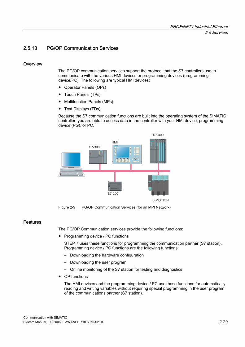
PROFINET / Industrial Ethernet 2.5 Services
Communication with SIMATIC System Manual, 09/2006, EWA 4NEB 710 6075-02 04 2-29
2.5.13 PG/OP Communication Services
Overview The PG/OP communication services support the protocol that the S7 controllers use to communicate with the various HMI devices or programming devices (programming device/PC). The following are typical HMI devices: ● Operator Panels (OPs) ● Touch Panels (TPs) ● Multifunction Panels (MPs) ● Text Displays (TDs) Because the S7 communication functions are built into the operating system of the SIMATIC controller, you are able to access data in the controller with your HMI device, programming device (PG), or PC.
s
Figure 2-9 PG/OP Communication Services (for an MPI Network)
Features The PG/OP Communication services provide the following functions: ● Programming device / PC functions
STEP 7 uses these functions for programming the communication partner (S7 station). Programming device / PC functions are the following functions: – Downloading the hardware configuration – Downloading the user program – Online monitoring of the S7 station for testing and diagnostics
● OP functions The HMI devices and the programming device / PC use these functions for automatically reading and writing variables without requiring special programming in the user program of the communications partner (S7 station).
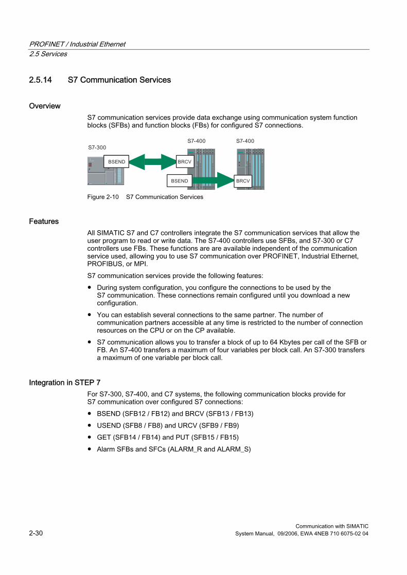
PROFINET / Industrial Ethernet 2.5 Services
Communication with SIMATIC 2-30 System Manual, 09/2006, EWA 4NEB 710 6075-02 04
2.5.14 S7 Communication Services
Overview S7 communication services provide data exchange using communication system function blocks (SFBs) and function blocks (FBs) for configured S7 connections.
Figure 2-10 S7 Communication Services
Features All SIMATIC S7 and C7 controllers integrate the S7 communication services that allow the user program to read or write data. The S7-400 controllers use SFBs, and S7-300 or C7 controllers use FBs. These functions are are available independent of the communication service used, allowing you to use S7 communication over PROFINET, Industrial Ethernet, PROFIBUS, or MPI. S7 communication services provide the following features: ● During system configuration, you configure the connections to be used by the
S7 communication. These connections remain configured until you download a new configuration.
● You can establish several connections to the same partner. The number of communication partners accessible at any time is restricted to the number of connection resources on the CPU or on the CP available.
● S7 communication allows you to transfer a block of up to 64 Kbytes per call of the SFB or FB. An S7-400 transfers a maximum of four variables per block call. An S7-300 transfers a maximum of one variable per block call.
Integration in STEP 7 For S7-300, S7-400, and C7 systems, the following communication blocks provide for S7 communication over configured S7 connections: ● BSEND (SFB12 / FB12) and BRCV (SFB13 / FB13) ● USEND (SFB8 / FB8) and URCV (SFB9 / FB9) ● GET (SFB14 / FB14) and PUT (SFB15 / FB15) ● Alarm SFBs and SFCs (ALARM_R and ALARM_S)
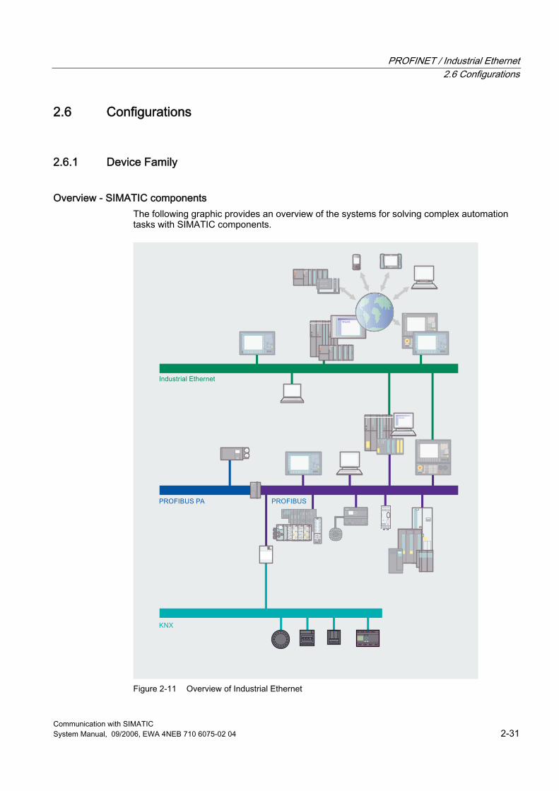
PROFINET / Industrial Ethernet 2.6 Configurations
Communication with SIMATIC System Manual, 09/2006, EWA 4NEB 710 6075-02 04 2-31
2.6 Configurations
2.6.1 Device Family
Overview - SIMATIC components The following graphic provides an overview of the systems for solving complex automation tasks with SIMATIC components.
Figure 2-11 Overview of Industrial Ethernet
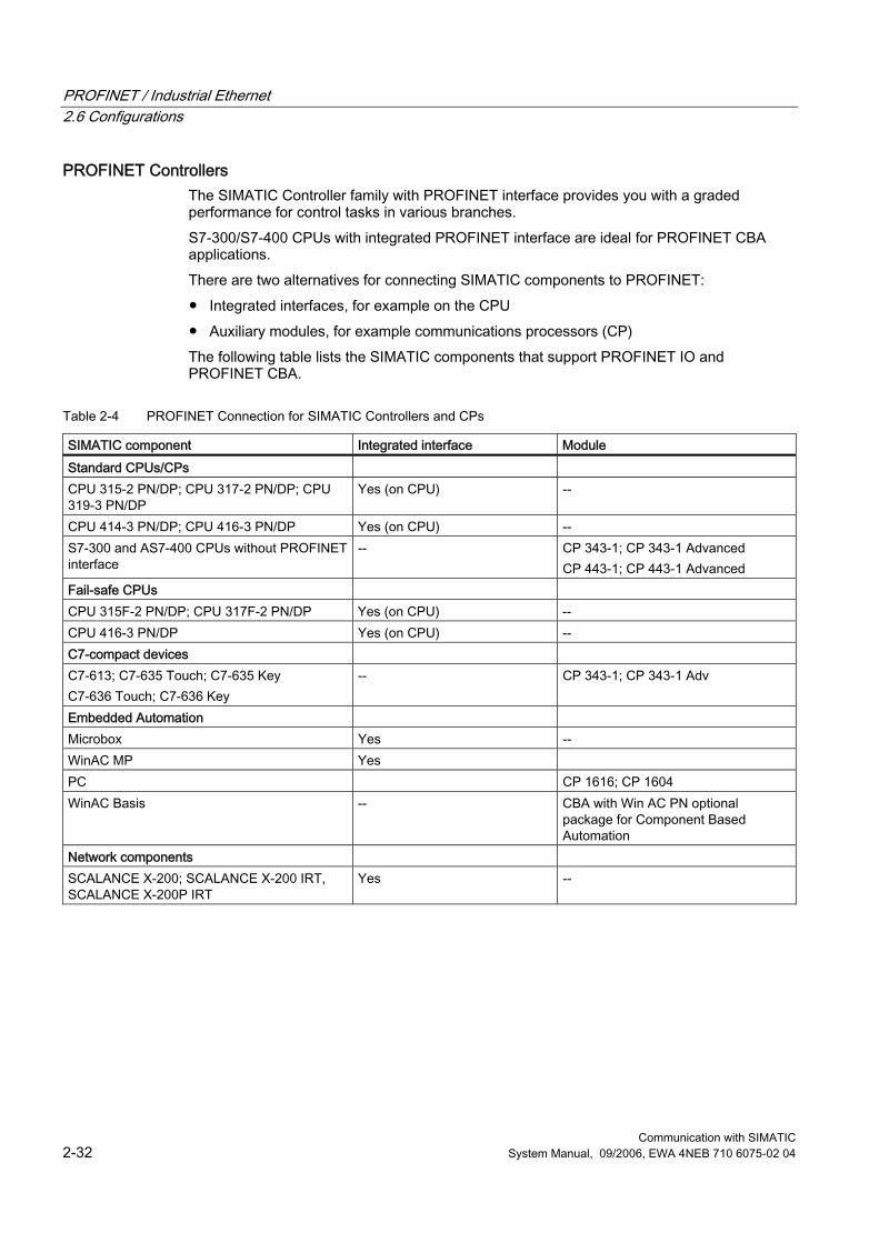
PROFINET / Industrial Ethernet 2.6 Configurations
Communication with SIMATIC 2-32 System Manual, 09/2006, EWA 4NEB 710 6075-02 04
PROFINET Controllers The SIMATIC Controller family with PROFINET interface provides you with a graded performance for control tasks in various branches. S7-300/S7-400 CPUs with integrated PROFINET interface are ideal for PROFINET CBA applications. There are two alternatives for connecting SIMATIC components to PROFINET: ● Integrated interfaces, for example on the CPU ● Auxiliary modules, for example communications processors (CP) The following table lists the SIMATIC components that support PROFINET IO and PROFINET CBA.
Table 2-4 PROFINET Connection for SIMATIC Controllers and CPs
SIMATIC component Integrated interface Module Standard CPUs/CPs CPU 315-2 PN/DP; CPU 317-2 PN/DP; CPU 319-3 PN/DP
Yes (on CPU) --
CPU 414-3 PN/DP; CPU 416-3 PN/DP Yes (on CPU) -- S7-300 and AS7-400 CPUs without PROFINET interface
-- CP 343-1; CP 343-1 Advanced CP 443-1; CP 443-1 Advanced
Fail-safe CPUs CPU 315F-2 PN/DP; CPU 317F-2 PN/DP Yes (on CPU) -- CPU 416-3 PN/DP Yes (on CPU) -- C7-compact devices C7-613; C7-635 Touch; C7-635 Key C7-636 Touch; C7-636 Key
-- CP 343-1; CP 343-1 Adv
Embedded Automation Microbox Yes -- WinAC MP Yes PC CP 1616; CP 1604 WinAC Basis -- CBA with Win AC PN optional
package for Component Based Automation
Network components SCALANCE X-200; SCALANCE X-200 IRT, SCALANCE X-200P IRT
Yes --
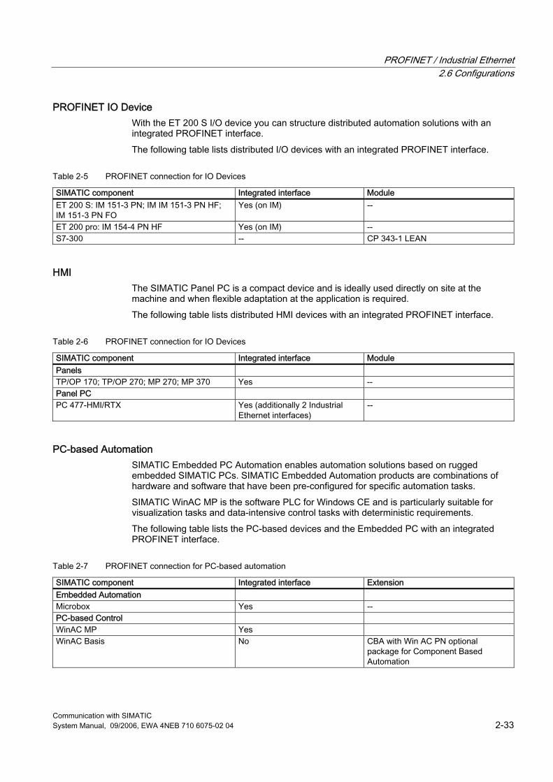
PROFINET / Industrial Ethernet 2.6 Configurations
Communication with SIMATIC System Manual, 09/2006, EWA 4NEB 710 6075-02 04 2-33
PROFINET IO Device With the ET 200 S I/O device you can structure distributed automation solutions with an integrated PROFINET interface. The following table lists distributed I/O devices with an integrated PROFINET interface.
Table 2-5 PROFINET connection for IO Devices
SIMATIC component Integrated interface Module ET 200 S: IM 151-3 PN; IM IM 151-3 PN HF; IM 151-3 PN FO
Yes (on IM) --
ET 200 pro: IM 154-4 PN HF Yes (on IM) -- S7-300 -- CP 343-1 LEAN
HMI The SIMATIC Panel PC is a compact device and is ideally used directly on site at the machine and when flexible adaptation at the application is required. The following table lists distributed HMI devices with an integrated PROFINET interface.
Table 2-6 PROFINET connection for IO Devices
SIMATIC component Integrated interface Module Panels TP/OP 170; TP/OP 270; MP 270; MP 370 Yes -- Panel PC PC 477-HMI/RTX Yes (additionally 2 Industrial
Ethernet interfaces) --
PC-based Automation SIMATIC Embedded PC Automation enables automation solutions based on rugged embedded SIMATIC PCs. SIMATIC Embedded Automation products are combinations of hardware and software that have been pre-configured for specific automation tasks. SIMATIC WinAC MP is the software PLC for Windows CE and is particularly suitable for visualization tasks and data-intensive control tasks with deterministic requirements. The following table lists the PC-based devices and the Embedded PC with an integrated PROFINET interface.
Table 2-7 PROFINET connection for PC-based automation
SIMATIC component Integrated interface Extension Embedded Automation Microbox Yes -- PC-based Control WinAC MP Yes WinAC Basis No CBA with Win AC PN optional
package for Component Based Automation
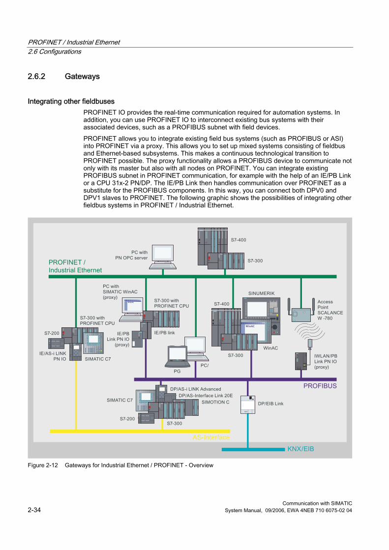
PROFINET / Industrial Ethernet 2.6 Configurations
Communication with SIMATIC 2-34 System Manual, 09/2006, EWA 4NEB 710 6075-02 04
2.6.2 Gateways
Integrating other fieldbuses PROFINET IO provides the real-time communication required for automation systems. In addition, you can use PROFINET IO to interconnect existing bus systems with their associated devices, such as a PROFIBUS subnet with field devices. PROFINET allows you to integrate existing field bus systems (such as PROFIBUS or ASI) into PROFINET via a proxy. This allows you to set up mixed systems consisting of fieldbus and Ethernet-based subsystems. This makes a continuous technological transition to PROFINET possible. The proxy functionality allows a PROFIBUS device to communicate not only with its master but also with all nodes on PROFINET. You can integrate existing PROFIBUS subnet in PROFINET communication, for example with the help of an IE/PB Link or a CPU 31x-2 PN/DP. The IE/PB Link then handles communication over PROFINET as a substitute for the PROFIBUS components. In this way, you can connect both DPV0 and DPV1 slaves to PROFINET. The following graphic shows the possibilities of integrating other fieldbus systems in PROFINET / Industrial Ethernet.
Figure 2-12 Gateways for Industrial Ethernet / PROFINET - Overview
PROFINET / Industrial Ethernet 2.6 Configurations
Communication with SIMATIC System Manual, 09/2006, EWA 4NEB 710 6075-02 04 2-35
You configure PROFINET IO devices and the network components in STEP 7. Here, PROFINET IO also provides a diagnostic tool for troubleshooting. The IE/PB Link PN IO is a gateway that links the Industrial Ethernet (management level) and PROFIBUS (cell level / field level) network types. The IE/PB Link PN IO supports access to all PROFIBUS DP slaves connected to the lower-level PROFIBUS. The IE/PB Link PN IO is an essential component of PROFINET IO. In this case, it provides the connection between the PROFINET IO controllers on Industrial Ethernet and the PROFINET IO devices (DP slaves on PROFIBUS). From the perspective of the PROFINET IO controller on Industrial Ethernet, there is no difference between accessing PROFINET IO devices connected to Industrial Ethernet and accessing PROFIBUS DP slaves connected to PROFIBUS DP. IE/PB Link PN IO serves as a proxy for the DP slaves that are connected to PROFIBUS DP and have the following tasks: ● Parameterization for field devices (data record routing)
You can use the IE/PB Link PN IO as a router for data records that are forwarded to field devices (DP slaves). This enables devices that are not directly connected to PROFIBUS and, thus, have no direct access to the field devices (DP slaves) to transfer data records to the field devices via IE/PB Link PN IO> For example, the SIMATIC Process Device Manager (PDM) tool generates these types of data records for parameter assignment of field devices.
● Subnet-overlapping S7 connections for HMI operation The IE/PB Link PN IO transmits the communication over S7 connections. This service is used for HMI applications (PC stations), for example. In addition, the following functions are supported:
● PG/OP communication PG/OP communication is used for loading programs and configuration data, testing and diagnostic functions, and operator control and monitoring (HMI systems) of a plant.
Further Information Further information about the topic of coupling various networks is available in the Industrial Communication for Automation and Drives catalog in Chapter 8. The catalog can be found on the Homepage of the A&D under the address: http://www.automation.siemens.com/net/html_76/support/printkatalog.htm. An overview of all the catalogs with the possibility of ordering them is provided under the address: http://www.automation.siemens.com/infocenter/order_form.aspx?lang=en.

PROFINET / Industrial Ethernet 2.6 Configurations
Communication with SIMATIC 2-36 System Manual, 09/2006, EWA 4NEB 710 6075-02 04

Communication with SIMATIC System Manual, 09/2006, EWA 4NEB 710 6075-02 04 3-1
Industrial Wireless LAN 33.1 Introduction
Overview The SIMATIC NET device family provides communications products for mobile data data transfer in accordance with the open wireless LAN standard IEEE 802.11. The SCALANCE W device family in which the extension of the wireless LAN standard "Industrial Wireless LAN" is implemented is available to this purpose.
Figure 3-1 Industrial Wireless LAN - Overview
Industrial Wireless LAN 3.1 Introduction
Communication with SIMATIC 3-2 System Manual, 09/2006, EWA 4NEB 710 6075-02 04
The extended standard Industrial WLAN requires minimum updating times for high-performance applications. This allows the data transfer of process-critical data, such as alarm messages, in addition to the non-time-critical communication (WLAN) for service and diagnostics. The products of the SCALANCE W device family are designed for the particular requirements of an industrial environment with IP 65 degree of protection. In addition to the standard wired network media supported by Ethernet, PROFINET IO also supports wireless communication with Industrial Wireless LAN (IWLAN). Implementing a wireless solution allows you to replace electrical connections that are naturally subject to wear (for example, contact conductors). A wireless solution also allows you to use automated guided vehicles or customized operator and maintenance devices. Advantages of a wireless communication network ● Increase in the competitiveness since the mobility and flexibility simplify maintenance
work, reduce service costs and stoppage times and allow the personnel to be deployed optimally.
● Work orders can be received and acknowledged online. ● The system solution is tested and well-proven because the network components,
communications processors, and software are perfectly matched to each other. ● Remote diagnostics for different production machines from a central service location
reduces service costs. ● Inaccessible installation locations can be easily reached without labor-intensive cabling. ● Fast commissioning of new system parts due to reduced effort for installing the
communication network. ● No wear and tear of rotating and moving equipment or system components. ● Cost-effective connection to devices in corrosive environments.

Industrial Wireless LAN 3.1 Introduction
Communication with SIMATIC System Manual, 09/2006, EWA 4NEB 710 6075-02 04 3-3
Primary Advantages ● Communication with moving nodes
In the case of electrical telpher lines, the wireless connection saves the entire busbar layout for data. Furthermore, the travel paths can be easily changed. If rotating equipment is incorporated in a data network, wear on the slip rings is avoided. The same advantage applies to substitution of cable carriers.
● Communication with mobile nodes and mobile data acquisition The user can acquire data and supply it to central data processing using mobile industrial-rated Internet PADs such as MOBIC (Mobile Industrial Communicator). In this case, the mobile handhelds are no longer assigned to a machine or a process but, instead, to a user (fewer devices required). IWLAN enables the radio connection between nodes and the radio network to be monitored. If a node exits the radio field or the radio connection is suddenly broken, a warning is automatically sent to the management or control level.
● Mobile service and diagnostics When an error occurs, the problem can be analyzed on the spot, and targeted information for fast remedial action can be provided via the wireless MOBIC Internet PAD. The spare parts inventory in the warehouse can be checked directly, and spare parts can be ordered online, if necessary. An IWLAN radio network enables transmission of both "noncritical" service and diagnostic data as well as process-critical data requiring a high level of performance.
● Flexible production in time-limited configurations and communication with remote units Automobile manufacturing plants, in particular, are subject to fast layout changes. Flexible production enables customer demands to be implemented quickly without significant retrofit times. Production units can be quickly integrated into the data network without significant effort required for connections using wireless data networking. Moreover, test configurations can be implemented quickly.
Further Information Brochure "Industrial communication for automation". ● Introductory information about industrial communication ● http://www.automation.siemens.com/net/html_76/ftp/presales/k-schrift_e.pdf Catalog IK PI 2007 "Industrial Communication for Automation and Drives", ● Device overview and ordering data for industrial communication ● http://www.automation.siemens.com/net/html_76/support/printkatalog.htm "Fundamentals of Industrial Wireless LAN": System Manual ● http://support.automation.siemens.com/WW/view/en/9975764 SIEMENS information about Industrial Mobile Communication : ● http://www.automation.siemens.com/net/html_76/produkte/050_produkte.htm
Industrial Wireless LAN 3.2 Properties
Communication with SIMATIC 3-4 System Manual, 09/2006, EWA 4NEB 710 6075-02 04
3.2 Properties
3.2.1 Basics
Overview The Industrial Wireless LAN products (SCALANCE W) are based on the WLAN standards. They stand out thanks to their rugged design and high IP65 rating as well as integrated security functions. In addition, SCALANCE W offers functions with which field devices can be linked to controllers at high performance levels:
Radio Transmission in Free Space Unlike LAN cabling which uses copper or fiber optic cables, a wireless local network uses free space as the transmission medium (WLAN network in accordance with IEEE 802.11). Information is transmitted through space in the form of electromagnetic waves. Due to physical factors, the available frequency spectrum for transmission is limited to electromagnetic waves on earth. Each frequency can, depending on the transmitter power, be assigned only once in a certain radius around the transmitter (Shared Medium).
Features There are many unfavorable influences that can impair a radio connection in the industrial field. Consequently, constant boundary conditions for radio transmission cannot be guaranteed. Automation systems, in particular, require that throughput times be predictable and that a defined portion of the available data rate be allocated to devices (e.g., PLC) that have stringent requirements for radio communication. Industrial Wireless LAN (IWLAN) satisfies the stringent reliability and performance requirements for radio communication by defining predictable throughput times and data rates. Only IWLAN of SIMATIC NET offers this function. To overcome the multipath propagation that occurs intensively in assembly shops and the associated attenuating and extinguishing effects on radio waves, the radio modules are equipped with two antennas (Antenna Diversity). Consequently, the receiver has the option of selecting the strongest of the two signals received. The modules are able to switch from the maximum data rate to a lower data rate if the quality of the transmission link changes permanently (number of nodes, variable distance between nodes and access point) in order to ensure reliable transmission of data at all times. The design of products also satisfies the requirements for harsh industrial environments and provides for easy installation. In addition, the modules also provide the convenience of an IT component, including features such as Web-based management with SNMP or sending of e-mails or SMS messages.
Industrial Wireless LAN 3.2 Properties
Communication with SIMATIC System Manual, 09/2006, EWA 4NEB 710 6075-02 04 3-5
3.2.2 Network Architectures
Overview There are two different Wireless LAN network types: ● Infrastructure mode
Connection of nodes over a common access point ● Ad hoc network
Direct connection between nodes
Infrastructure Mode In infrastructure mode, communication takes place over an access point. The nodes have to log on to the access point and transmit on the channel specified there. In the simplest case, a group of IEE 802.11 nodes are located in the radio area of this access point. A network of this type is referred to as a Basic Service Set (BSS). If the radio area does not reach an access point because either the sensing range is too small or too few nodes can be operated, two or more overlapping BSSs can be operated in a common network (Extended Service Set, ESS). The infrastructure mode enables large networks to be configured and, in particular, supports operation within an Ethernet network. Wireless LAN in accordance with IEEE 802.11 is also referred to as Wireless Ethernet.
Ad hoc Network The simplest form of Wireless LAN network in accordance IEEE 802.11 is referred to as an ad-hoc network. In this type of spontaneous network (Independent Basic Service Set, IBSS), the radio cards of individual devices can establish fast, simple networks without a large network structure and without user intervention. These networks are used for temporary data exchange over short distances.
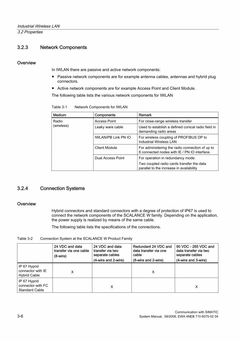
Industrial Wireless LAN 3.2 Properties
Communication with SIMATIC 3-6 System Manual, 09/2006, EWA 4NEB 710 6075-02 04
3.2.3 Network Components
Overview In IWLAN there are passive and active network components: ● Passive network components are for example antenna cables, antennas and hybrid plug
connectors. ● Active network components are for example Access Point and Client Module. The following table lists the various network components for IWLAN
Table 3-1 Network Components for IWLAN
Medium Components Remark Access Point For close-range wireless transfer Leaky ware cable Used to establish a defined conical radio field in
demanding radio areas IWLAN/PB Link PN IO For wireless coupling of PROFIBUS DP to
Industrial Wireless LAN Client Module For administering the radio connection of up to
8 connected nodes with IE / PN IO interface.
Radio (wireless)
Dual Access Point For operation in redundancy mode. Two coupled radio cards transfer the data parallel to the increase in availability
3.2.4 Connection Systems
Overview Hybrid connectors and standard connectors with a degree of protection of IP67 is used to connect the network components of the SCALANCE W family. Depending on the application, the power supply is realized by means of the same cable. The following table lists the specifications of the connections.
Table 3-2 Connection System at the SCALANCE W Product Family
24 VDC and data transfer via one cable (8-wire)
24 VDC and data transfer via two separate cables (4-wire and 2-wire)
Redundant 24 VDC and data transfer via one cable (8-wire and 2-wire)
90 VDC - 265 VDC and data transfer via two separate cables (4-wire and 3-wire)
IP 67 Hyprid connector with IE Hybrid Cable
X
X
IP 67 Hyprid connector with FC Standard Cable
X
X
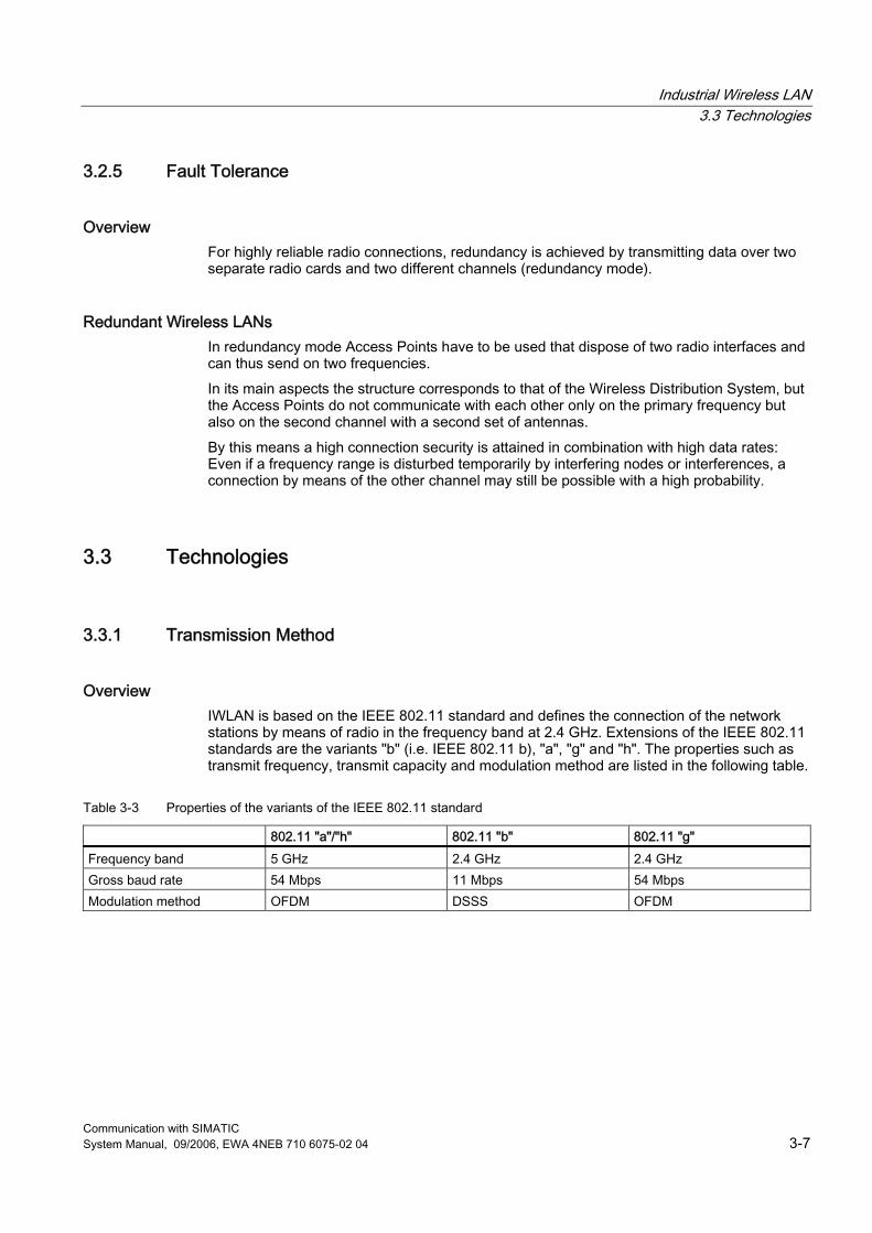
Industrial Wireless LAN 3.3 Technologies
Communication with SIMATIC System Manual, 09/2006, EWA 4NEB 710 6075-02 04 3-7
3.2.5 Fault Tolerance
Overview For highly reliable radio connections, redundancy is achieved by transmitting data over two separate radio cards and two different channels (redundancy mode).
Redundant Wireless LANs In redundancy mode Access Points have to be used that dispose of two radio interfaces and can thus send on two frequencies. In its main aspects the structure corresponds to that of the Wireless Distribution System, but the Access Points do not communicate with each other only on the primary frequency but also on the second channel with a second set of antennas. By this means a high connection security is attained in combination with high data rates: Even if a frequency range is disturbed temporarily by interfering nodes or interferences, a connection by means of the other channel may still be possible with a high probability.
3.3 Technologies
3.3.1 Transmission Method
Overview IWLAN is based on the IEEE 802.11 standard and defines the connection of the network stations by means of radio in the frequency band at 2.4 GHz. Extensions of the IEEE 802.11 standards are the variants "b" (i.e. IEEE 802.11 b), "a", "g" and "h". The properties such as transmit frequency, transmit capacity and modulation method are listed in the following table.
Table 3-3 Properties of the variants of the IEEE 802.11 standard
802.11 "a"/"h" 802.11 "b" 802.11 "g" Frequency band 5 GHz 2.4 GHz 2.4 GHz Gross baud rate 54 Mbps 11 Mbps 54 Mbps Modulation method OFDM DSSS OFDM
Industrial Wireless LAN 3.3 Technologies
Communication with SIMATIC 3-8 System Manual, 09/2006, EWA 4NEB 710 6075-02 04
Modulation Method A modulation in the sense of communications engineering is when the signal is "modulated onto" a carrier wave. The "sum" of carrier wave and Signal is transferred to the receiver that deducts the carrier wave from the received oscillation and thus obtains the pure signal again. More complex procedures described below are used to transfer digital data OFDM (Orthogonal Frequency Division Multiplexing) OFDM does not use only one frequency to transfer a signal, but rather transmits on several hundred to several thousand ones. The channels lie near each other in a narrow frequency band The massive parallel data transfer means that the data rate passing on the each individual channel is reduced drastically. Much more time is thus available to transfer the individual bits. The advantage in this process is the relatively high resistance to disturbances such as echoes or brief noise. Sequence Spread Spectrum (DSSS) A further method of transferring digital data is the adding of randomly generated bits. These random bits are added to the data flow by means of an XOR logic operation in such a manner that the random bits change much faster then the values of the data flow. The receiver subtracts this random bit from the received data flow and receives the unfalsified signal. To this purpose the receiver has to know the sequence of the random bit. These are generated on both ends of the transfer path by means of a key algorithm. To this purpose the key has to be exchanged beforehand and has to be known to the transmitter and receiver.
3.3.2 Access Methods
CSMA/CA A wired Ethernet network operates according to the CSMA/CD access method (Carrier Sense Multiple Access with Collision Detection). Once the ready-to-send node has listened in on the cable and identifies it to be free (Carrier Sense, CS), the data are transmitted. During transmission, the transmitting node can detect a collision (Collision Detection, CD) between itself and other simultaneously transmitting nodes (Multiple Access, MA) based on a faulted signal level, and thereby terminate the transmission. In a wireless network, this mechanism is applied in the same way except that collisions are deliberately avoided (Collision Avoidance, CA) to keep from reducing the net data throughput unnecessarily. For this reason, wireless LANs do not use the CSMA/CD method, in which permitted collisions are detected. Rather, wireless LANs use the CSMA/CA method (Carrier Sense Multiple Access with Collision Avoidance). Instead of physically listening in on the channel, wireless LANs use a communication protocol that reserves the channel for a certain amount of time. In this method, the node checks to see if the medium is free before starting transmission. The following access mechanisms are available at IWLAN:: ● Data Reservation: The bandwidth between an access point and a defined client is
reserved. This safeguards high, reliable performance for this client regardless of how many additional clients are operated at the access point.
● Rapid Roaming: This function enables movable stations to be rapidly passed on between various access points. These expansions to the standard allow high-performance wireless applications with PROFINET IO down to the field level.
Industrial Wireless LAN 3.4 Information Security in the IWLAN
Communication with SIMATIC System Manual, 09/2006, EWA 4NEB 710 6075-02 04 3-9
3.4 Information Security in the IWLAN
Overview Intrusion into IWLANs is possible because radio waves are not tied to a fixed medium, i.e., a wire, and because effects such as reflections and diffractions overlap. In addition, IWLAN is a "Shared Medium" meaning that all nodes endeavor to access the same network infrastructure. This is not the case in wired "Switched Ethernet." There, each node has an exclusive cable up to the switch that it does not have to share with any other node. Unless additional measures are taken, it is thus impossible to be certain which node is "tying up" the radio network and accessing the medium.
IEEE 802.11i The working committee 802.11i of the IEEE is handling the security of data transfer via WLANs. One focus of the working committee is the definition of encryption algorithms and authentication procedures for wireless data transfer.
Wired Equivalent Privacy (WEP) In this encryption procedure a password is used in order to generate the random sequences (see Section 3.3.1 - Transmission Modes). Each character of the telegram to be transferred is then encrypted or decoded with the next number from this sequence. This procedure is regarded as relatively insecure, since conclusions can be drawn from the encoded data flow about the key that is used. An improved procedure us Wi-Fi Protected Access (WPA)
WPA WPA represents the further development of WEP and is still regarded as the standard despite some weaknesses. In addition to technical modifications to the actual encryption algorithm, the course of the protocol was also changed. ● Passwords for the network access (authentication) are stored on a central server
(RADIUS) ● The key for the telegram transfer changes dynamically, thus making static attacks more
difficult. ● The key also includes the MAC address (the unique hardware identification) of the
transmitter, making faking of the transmitter address at messages more difficult.
WPA2 und Advanced Encryption Standard (AES) WPA2 differs from WPA mainly in the encryption procedure that is used: The weaknesses that have been identified at WPA no longer exist in the AES procedure that is used at WPA2. The "Advanced Encryption Standard" also "adds a key onto" the message, as at WEP. On the one hand one block of raw data at a time is processed with the same key respectively, on the other hand several processing passes are carried with respectively varying block limits.
Industrial Wireless LAN 3.5 Configurations
Communication with SIMATIC 3-10 System Manual, 09/2006, EWA 4NEB 710 6075-02 04
Extensible Authentication Protocol (EAP) EAP is a protocol that specifies the authentication method on which a client and server agree for the communication process.
MAC Filters MAC addresses (Media Access Control) are codes through which hardware elements (such as network cards, modules, motherboards) can be identified uniquely worldwide. The addresses usually encompass 6 bytes (48 bits) and are "wired fixed" in the corresponding components. When requested, the components identify themselves by returning their MAC address. In the network administration function filter tables with MAC addresses can be set up that allow or prohibit access for certain addresses. By this means a simple, even if comparatively insecure access protection can be implemented for the network. It is not impossible for MAC addresses to be manipulated (so-called "spoofing") so that MAC filters only offer sufficient security for a network in combination with other measures.
3.5 Configurations
3.5.1 Planning and Engineering
SINEMA E Lean The planning, simulation and configuration software SINEMA E Lean is used to plan and configure IWLAN applications. It can be used to visualize IWLAN networks for example according to coverage, data transfer rate, signal/noise ratio and overlapping with consideration of environmental and device characteristics
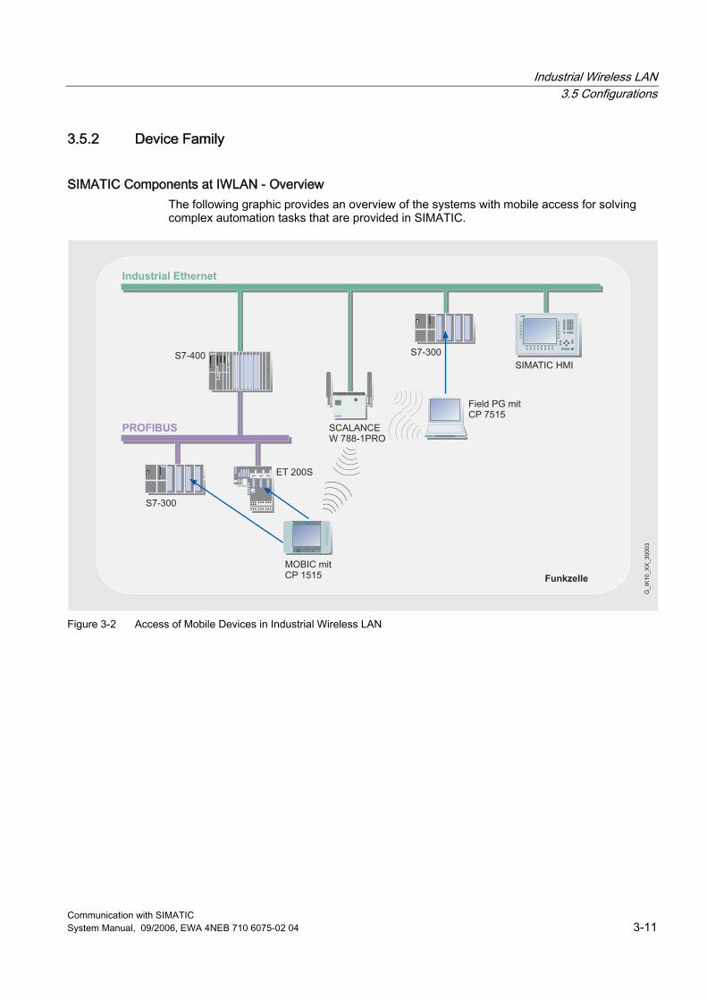
Industrial Wireless LAN 3.5 Configurations
Communication with SIMATIC System Manual, 09/2006, EWA 4NEB 710 6075-02 04 3-11
3.5.2 Device Family
SIMATIC Components at IWLAN - Overview The following graphic provides an overview of the systems with mobile access for solving complex automation tasks that are provided in SIMATIC.
������
����
���
��������� �������
�� ��������������
�������������������
������ ��
��������
����
�!�"��
#�$�������������
�#�!���%#�
���������
Figure 3-2 Access of Mobile Devices in Industrial Wireless LAN
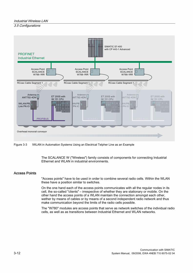
Industrial Wireless LAN 3.5 Configurations
Communication with SIMATIC 3-12 System Manual, 09/2006, EWA 4NEB 710 6075-02 04
Figure 3-3 IWLAN in Automation Systems Using an Electrical Telpher Line as an Example
The SCALANCE W ("Wireless") family consists of components for connecting Industrial Ethernet and WLAN in industrial environments.
Access Points "Access points" have to be used in order to combine several radio cells. Within the WLAN these have a position similar to switches. On the one hand each of the access points communicates with all the regular nodes in its cell, the so-called "clients" – irrespective of whether they are stationary or mobile. On the other hand the access points of a WLAN maintain the connection amongst each other, wether by means of cables or by means of a second independent radio network and thus make communication beyond the limits of the radio cells possible. The "W780" modules are access points that serve as network switches of the individual radio cells, as well as as transitions between Industrial Ethernet and WLAN networks.
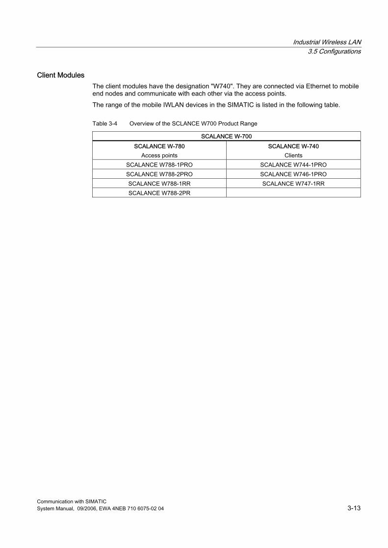
Industrial Wireless LAN 3.5 Configurations
Communication with SIMATIC System Manual, 09/2006, EWA 4NEB 710 6075-02 04 3-13
Client Modules The client modules have the designation "W740". They are connected via Ethernet to mobile end nodes and communicate with each other via the access points. The range of the mobile IWLAN devices in the SIMATIC is listed in the following table.
Table 3-4 Overview of the SCLANCE W700 Product Range
SCALANCE W-700 SCALANCE W-780
Access points SCALANCE W-740
Clients SCALANCE W788-1PRO SCALANCE W744-1PRO SCALANCE W788-2PRO SCALANCE W746-1PRO SCALANCE W788-1RR SCALANCE W747-1RR SCALANCE W788-2PR
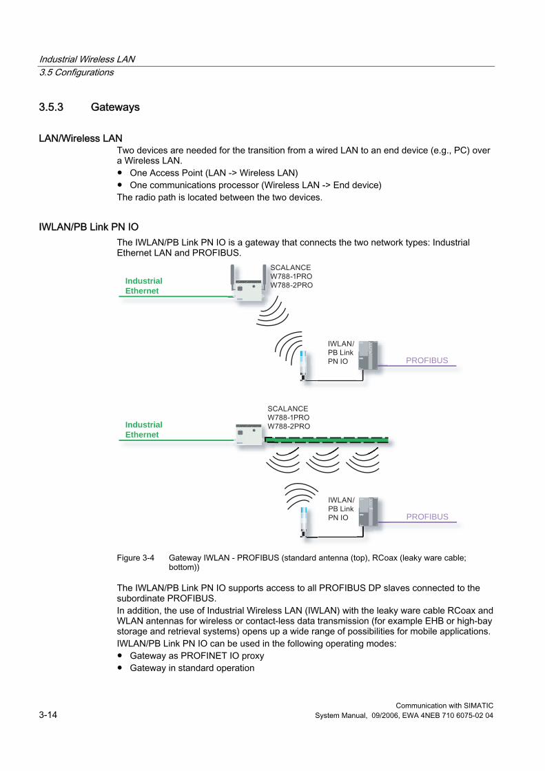
Industrial Wireless LAN 3.5 Configurations
Communication with SIMATIC 3-14 System Manual, 09/2006, EWA 4NEB 710 6075-02 04
3.5.3 Gateways
LAN/Wireless LAN Two devices are needed for the transition from a wired LAN to an end device (e.g., PC) over a Wireless LAN. ● One Access Point (LAN -> Wireless LAN) ● One communications processor (Wireless LAN -> End device) The radio path is located between the two devices.
IWLAN/PB Link PN IO The IWLAN/PB Link PN IO is a gateway that connects the two network types: Industrial Ethernet LAN and PROFIBUS.
PROFIBUS
IndustrialEthernet
PROFIBUS
IndustrialEthernet
Figure 3-4 Gateway IWLAN - PROFIBUS (standard antenna (top), RCoax (leaky ware cable;
bottom))
The IWLAN/PB Link PN IO supports access to all PROFIBUS DP slaves connected to the subordinate PROFIBUS. In addition, the use of Industrial Wireless LAN (IWLAN) with the leaky ware cable RCoax and WLAN antennas for wireless or contact-less data transmission (for example EHB or high-bay storage and retrieval systems) opens up a wide range of possibilities for mobile applications. IWLAN/PB Link PN IO can be used in the following operating modes: ● Gateway as PROFINET IO proxy ● Gateway in standard operation

Industrial Wireless LAN 3.5 Configurations
Communication with SIMATIC System Manual, 09/2006, EWA 4NEB 710 6075-02 04 3-15
Further Information For additional information on the S7-CPs for Industrial Ethernet, refer to the SIMATIC NET Manual Part BL 2 SIMATIC S7-CPs for Industrial Ethernet For basic information on the Industrial Wireless LAN, refer to the SIMATIC NET System Manual Basics of Industrial Wireless LAN

Industrial Wireless LAN 3.5 Configurations
Communication with SIMATIC 3-16 System Manual, 09/2006, EWA 4NEB 710 6075-02 04
Communication with SIMATIC System Manual, 09/2006, EWA 4NEB 710 6075-02 04 4-1
PROFIBUS 44.1 Introduction
Overview PROFIBUS is used to connect field devices, such as distributed I/O devices, valves or drives, to automation systems, such as SIMATIC S7, SIMOTION, SINUMERIK or PCs. PROFIBUS that is standardized in accordance with IEC 61158 and EN 50170 is a powerful, open and robust with fieldbus system with short reaction times. This open fieldbus standard is supported by the most important companies in the automation industry. PROFIBUS provides a fieldbus solution for the complete production and process automation with rapid and reliable data exchange as well as integrated diagnostics capabilities. PROFIBUS can also be used in hazardous areas as well as for fail-safe applications and HART devices.
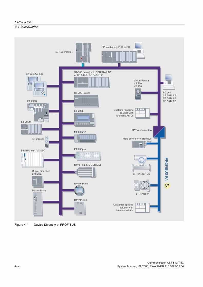
PROFIBUS 4.1 Introduction
Communication with SIMATIC 4-2 System Manual, 09/2006, EWA 4NEB 710 6075-02 04
Figure 4-1 Device Diversity at PROFIBUS
PROFIBUS 4.1 Introduction
Communication with SIMATIC System Manual, 09/2006, EWA 4NEB 710 6075-02 04 4-3
Advantages In comparison to conventional operation of process I/O, PROFIBUS provides many advantages: ● Reduced planning and engineering costs and time ● Reduced installation and start-up costs through
– Reduced effort required for wiring, – Abolition of termination modules, – Mounting in the field and
● Rationalization of connection and power distribution ● Reduced operating and maintenance costs due to embedded diagnostics in devices
Further Information Brochure "Industrial communication for automation". ● Introductory information about industrial communication ● http://www.automation.siemens.com/net/html_76/ftp/presales/k-schrift_e.pdf Catalog IK PI 2007 "Industrial Communication for Automation and Drives", ● Device overview and ordering data for industrial communication ● http://www.automation.siemens.com/net/html_76/support/printkatalog.htm Isochronous Mode function manual: ● Complete overview of the isochronous mode system function ● http://support.automation.siemens.com/WW/view/en/15218045 "PROFIBUS - Technology and Application" System Description ● Comprehensive overview of the PROFIBUS technology ● http://www.profibus.com/pall/meta/downloads/article/00454/ PROFIBUS international homepage: ● http://www.profibus.com/
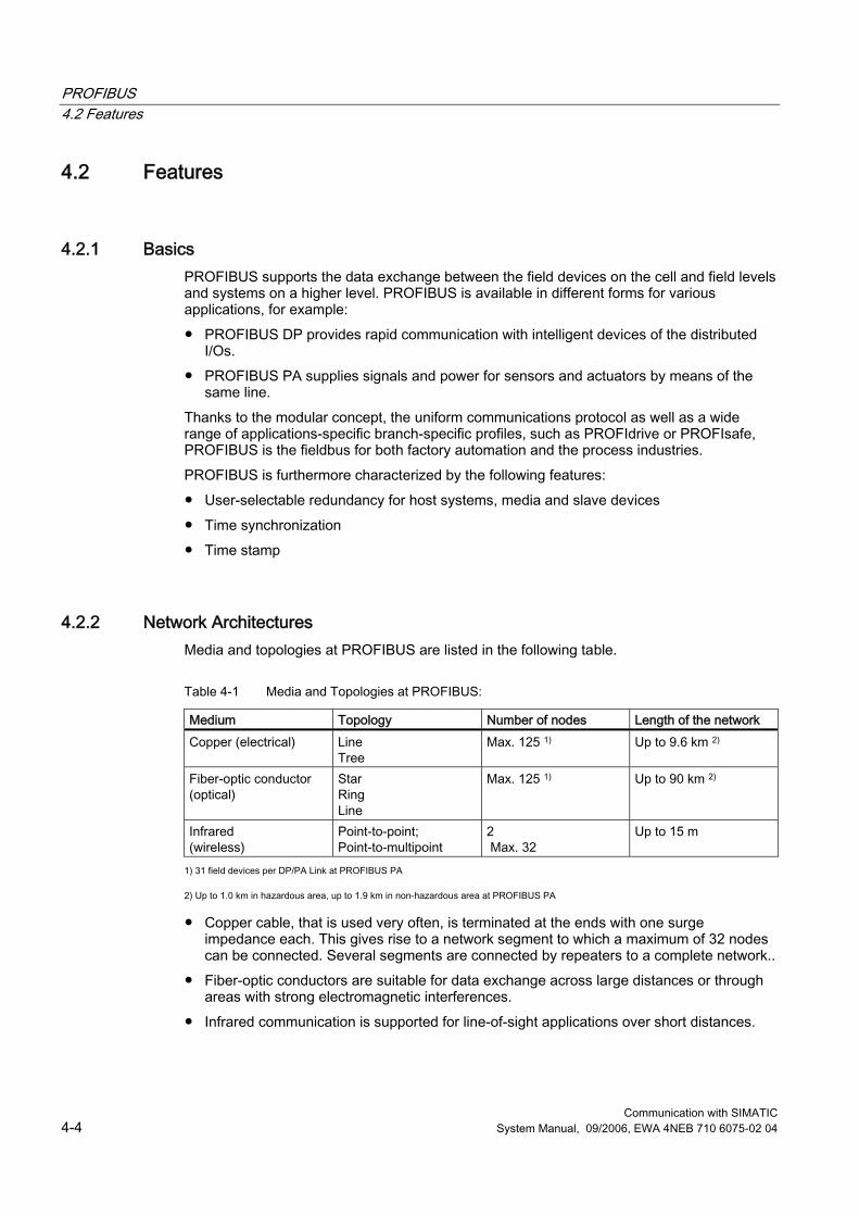
PROFIBUS 4.2 Features
Communication with SIMATIC 4-4 System Manual, 09/2006, EWA 4NEB 710 6075-02 04
4.2 Features
4.2.1 Basics PROFIBUS supports the data exchange between the field devices on the cell and field levels and systems on a higher level. PROFIBUS is available in different forms for various applications, for example: ● PROFIBUS DP provides rapid communication with intelligent devices of the distributed
I/Os. ● PROFIBUS PA supplies signals and power for sensors and actuators by means of the
same line. Thanks to the modular concept, the uniform communications protocol as well as a wide range of applications-specific branch-specific profiles, such as PROFIdrive or PROFIsafe, PROFIBUS is the fieldbus for both factory automation and the process industries. PROFIBUS is furthermore characterized by the following features: ● User-selectable redundancy for host systems, media and slave devices ● Time synchronization ● Time stamp
4.2.2 Network Architectures Media and topologies at PROFIBUS are listed in the following table.
Table 4-1 Media and Topologies at PROFIBUS:
Medium Topology Number of nodes Length of the network Copper (electrical) Line
Tree Max. 125 1) Up to 9.6 km 2)
Fiber-optic conductor (optical)
Star Ring Line
Max. 125 1) Up to 90 km 2)
Infrared (wireless)
Point-to-point; Point-to-multipoint
2 Max. 32
Up to 15 m
1) 31 field devices per DP/PA Link at PROFIBUS PA 2) Up to 1.0 km in hazardous area, up to 1.9 km in non-hazardous area at PROFIBUS PA ● Copper cable, that is used very often, is terminated at the ends with one surge
impedance each. This gives rise to a network segment to which a maximum of 32 nodes can be connected. Several segments are connected by repeaters to a complete network..
● Fiber-optic conductors are suitable for data exchange across large distances or through areas with strong electromagnetic interferences.
● Infrared communication is supported for line-of-sight applications over short distances.
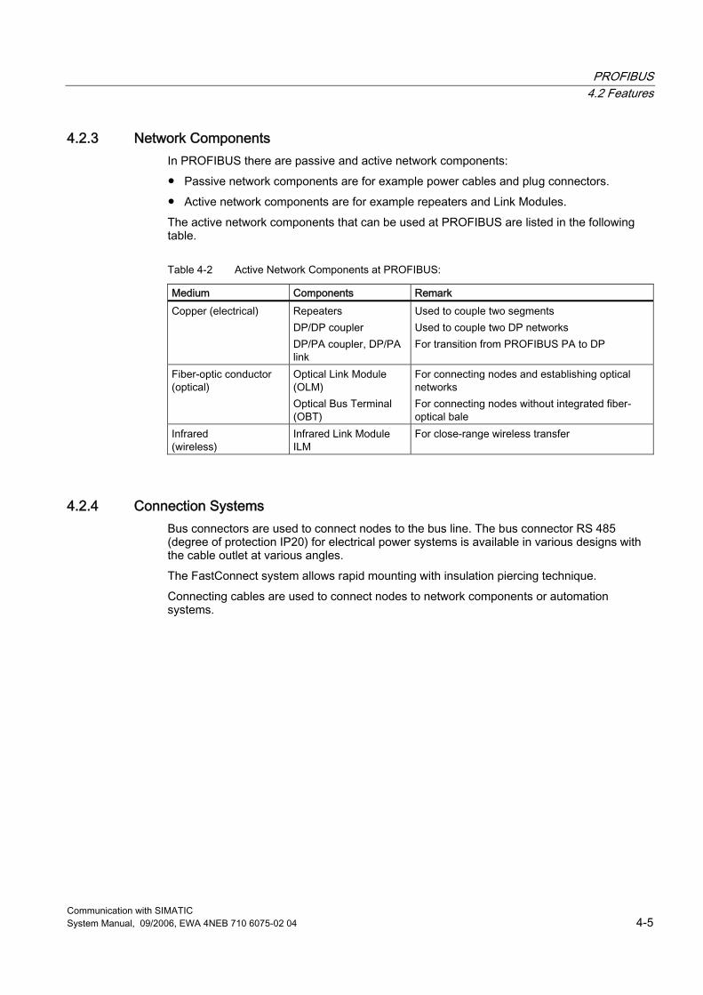
PROFIBUS 4.2 Features
Communication with SIMATIC System Manual, 09/2006, EWA 4NEB 710 6075-02 04 4-5
4.2.3 Network Components In PROFIBUS there are passive and active network components: ● Passive network components are for example power cables and plug connectors. ● Active network components are for example repeaters and Link Modules. The active network components that can be used at PROFIBUS are listed in the following table.
Table 4-2 Active Network Components at PROFIBUS:
Medium Components Remark Copper (electrical) Repeaters
DP/DP coupler DP/PA coupler, DP/PA link
Used to couple two segments Used to couple two DP networks For transition from PROFIBUS PA to DP
Fiber-optic conductor (optical)
Optical Link Module (OLM) Optical Bus Terminal (OBT)
For connecting nodes and establishing optical networks For connecting nodes without integrated fiber-optical bale
Infrared (wireless)
Infrared Link Module ILM
For close-range wireless transfer
4.2.4 Connection Systems Bus connectors are used to connect nodes to the bus line. The bus connector RS 485 (degree of protection IP20) for electrical power systems is available in various designs with the cable outlet at various angles. The FastConnect system allows rapid mounting with insulation piercing technique. Connecting cables are used to connect nodes to network components or automation systems.
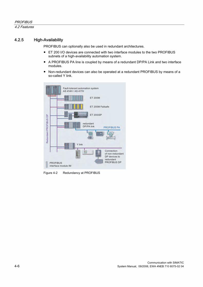
PROFIBUS 4.2 Features
Communication with SIMATIC 4-6 System Manual, 09/2006, EWA 4NEB 710 6075-02 04
4.2.5 High-Availability PROFIBUS can optionally also be used in redundant architectures. ● ET 200 I/O devices are connected with two interface modules to the two PROFIBUS
subnets of a high-availability automation system. ● A PROFIBUS PA line is coupled by means of a redundant DP/PA Link and two interface
modules. ● Non-redundant devices can also be operated at a redundant PROFIBUS by means of a
so-called Y link.
Figure 4-2 Redundancy at PROFIBUS
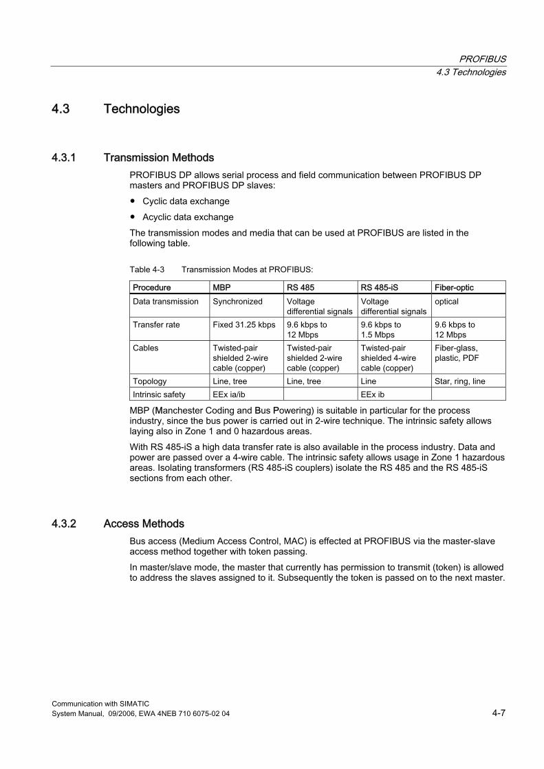
PROFIBUS 4.3 Technologies
Communication with SIMATIC System Manual, 09/2006, EWA 4NEB 710 6075-02 04 4-7
4.3 Technologies
4.3.1 Transmission Methods PROFIBUS DP allows serial process and field communication between PROFIBUS DP masters and PROFIBUS DP slaves: ● Cyclic data exchange ● Acyclic data exchange The transmission modes and media that can be used at PROFIBUS are listed in the following table.
Table 4-3 Transmission Modes at PROFIBUS:
Procedure MBP RS 485 RS 485-iS Fiber-optic Data transmission Synchronized Voltage
differential signals Voltage differential signals
optical
Transfer rate Fixed 31.25 kbps 9.6 kbps to 12 Mbps
9.6 kbps to 1.5 Mbps
9.6 kbps to 12 Mbps
Cables Twisted-pair shielded 2-wire cable (copper)
Twisted-pair shielded 2-wire cable (copper)
Twisted-pair shielded 4-wire cable (copper)
Fiber-glass, plastic, PDF
Topology Line, tree Line, tree Line Star, ring, line Intrinsic safety EEx ia/ib EEx ib
MBP (Manchester Coding and Bus Powering) is suitable in particular for the process industry, since the bus power is carried out in 2-wire technique. The intrinsic safety allows laying also in Zone 1 and 0 hazardous areas. With RS 485-iS a high data transfer rate is also available in the process industry. Data and power are passed over a 4-wire cable. The intrinsic safety allows usage in Zone 1 hazardous areas. Isolating transformers (RS 485-iS couplers) isolate the RS 485 and the RS 485-iS sections from each other.
4.3.2 Access Methods Bus access (Medium Access Control, MAC) is effected at PROFIBUS via the master-slave access method together with token passing. In master/slave mode, the master that currently has permission to transmit (token) is allowed to address the slaves assigned to it. Subsequently the token is passed on to the next master.
PROFIBUS 4.4 Services
Communication with SIMATIC 4-8 System Manual, 09/2006, EWA 4NEB 710 6075-02 04
4.4 Services
4.4.1 PROFIBUS DP services
Overview PROFIBUS DP (distributed I/Os) is used to connect the following devices: ● Controllers, PCs, HMI devices ● Distributed field devices, for example SIMATIC ET 200 ● Valves ● Drives Thanks to its rapid response times PROFIBUS DP is particularly suitable for the manufacturing industry.
Features As at a centralized I/O devices access to the distributed I/Os is carried out by means of the configured device address. The STEP 7 user program can read and write data to these addresses in the same manner as to the central I/O devices. This means that the distributed I/Os can be addresses through direct I/O access or through the process image exchange. PROFIBUS offers various performance levels: ● The basic functionality (DPV0) includes the cyclic data exchange of process data
between the master and PROFIBUS DP slaves as well as workstation- module- and channel-specific diagnostics.
● The extensions in accordance with DPV1 encompass acyclic data traffic during operation for: – Parameterization as well as operator control & monitoring (non-time-critical) – Handling of interrupts (time-critical)
● Isochronous mode and data exchange broadcast (DPV2): – Isochronous mode is characterized by a deterministic and clock-synchronized
behavior. The synchronized execution cycles ensure that the data are transmitted at consistently equidistant time intervals. This ensures that demanding control systems, high-precision position processes and rapid motion control applications can be realized.
– Data exchange broadcast means that PROFIBUS DP slaves communicate with each other using broadcasting without going through the master, thus reducing the bus response times notably.
The additional "HART on PROFIBUS DP" profile also allows communication with HART devices.
Integration in STEP 7 You use STEP 7 to configure the distributed I/O (such as ET 200 stations) as part of the hardware configuration for the controller. With the vendor-supplied GSD file, you can also use STEP 7 to configure the addresses for slave devices from other (non-SIMATIC) manufacturers.
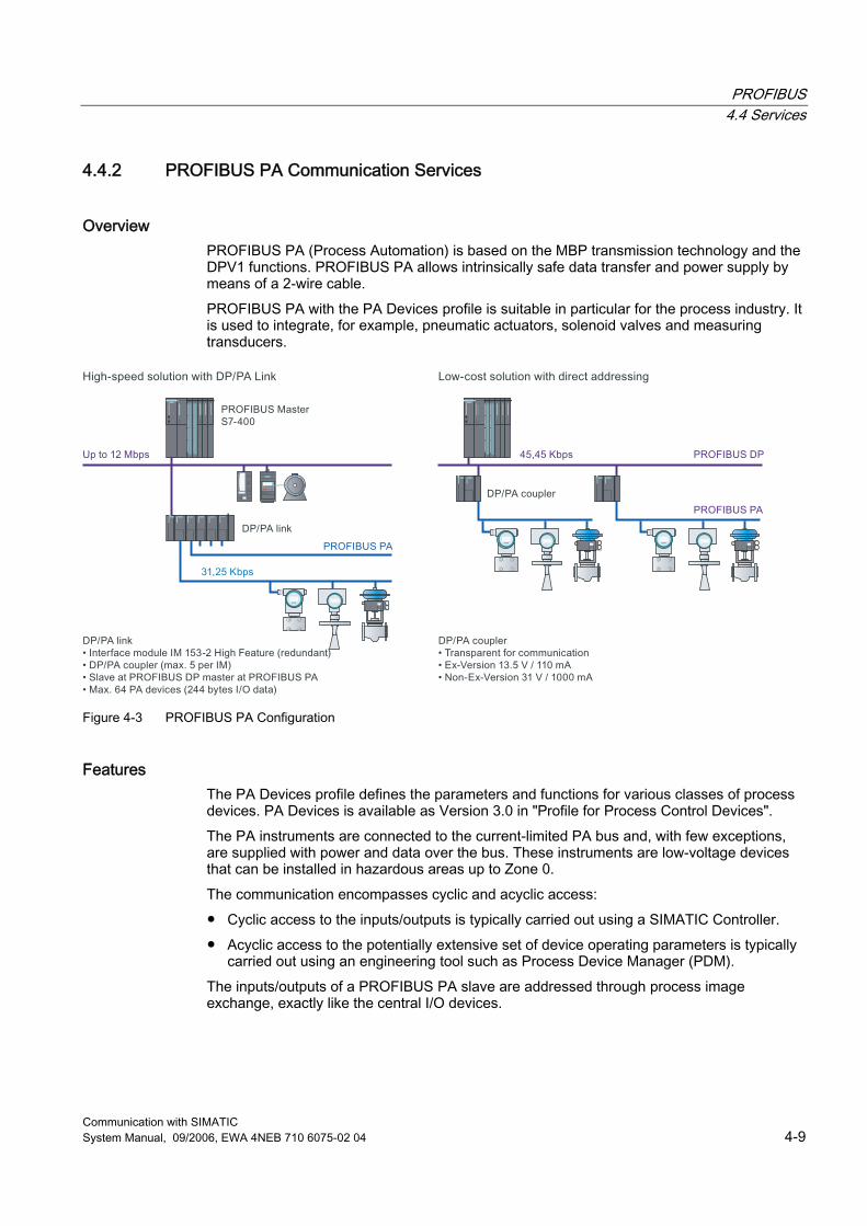
PROFIBUS 4.4 Services
Communication with SIMATIC System Manual, 09/2006, EWA 4NEB 710 6075-02 04 4-9
4.4.2 PROFIBUS PA Communication Services
Overview PROFIBUS PA (Process Automation) is based on the MBP transmission technology and the DPV1 functions. PROFIBUS PA allows intrinsically safe data transfer and power supply by means of a 2-wire cable. PROFIBUS PA with the PA Devices profile is suitable in particular for the process industry. It is used to integrate, for example, pneumatic actuators, solenoid valves and measuring transducers.
Figure 4-3 PROFIBUS PA Configuration
Features The PA Devices profile defines the parameters and functions for various classes of process devices. PA Devices is available as Version 3.0 in "Profile for Process Control Devices". The PA instruments are connected to the current-limited PA bus and, with few exceptions, are supplied with power and data over the bus. These instruments are low-voltage devices that can be installed in hazardous areas up to Zone 0. The communication encompasses cyclic and acyclic access: ● Cyclic access to the inputs/outputs is typically carried out using a SIMATIC Controller. ● Acyclic access to the potentially extensive set of device operating parameters is typically
carried out using an engineering tool such as Process Device Manager (PDM). The inputs/outputs of a PROFIBUS PA slave are addressed through process image exchange, exactly like the central I/O devices.
PROFIBUS 4.4 Services
Communication with SIMATIC 4-10 System Manual, 09/2006, EWA 4NEB 710 6075-02 04
All the bus components used as PROFIBUS PA differ from those used at PROFIBUS DP, for example: ● Cables ● Plug connectors ● Repeaters ● Terminations These differences are due to the differing electrical properties of the bus. PROFIBUS PA allows a transfer rate of 31.25 kbps and can have a line or tree structure. PROFIBUS PA is connected to PROFIBUS DP by means of the following active network components: ● DP/PA couplers for small volumes of data ● DP/PA links for large volumes of data DP/PA couplers allow the following segment lengths: ● Up to 1 km in an Ex area ● Up to 1.9 km in a non-Ex area
Integration in STEP 7 As with PROFIBUS DP devices, PROFIBUS PA devices are also described by GSD files by the manufacturer. These GSD files are installed in the STEP 7 hardware configuration. Afterwards the PA devices are displayed in the device catalog.
PROFIBUS 4.4 Services
Communication with SIMATIC System Manual, 09/2006, EWA 4NEB 710 6075-02 04 4-11
4.4.3 PROFIdrive
Overview PROFIdrive is used to include drives in automation solutions from simple frequency converters to highly dynamic servo controller. To this purpose PROFIdrive defines the device behavior and the methods for accessing drive data at PROFIBUS.
Features In order to accomplish the various tasks that modern drives must perform, PROFIdrive defines six application classes: ● Class 1 defines a standard drive that is controlled via a main setpoint, e.g., the speed
setpoint. ● Class 2 defines a standard drive with technology function. The process is divided into
subprocesses for this class. Drive tasks are issued to the drive device, requiring direct data exchange between the individual drives.
● Class 3 defines a positioning drive that includes a position controller. The positioning requests are started and transferred via PROFIBUS.
● Classes 4 and 5 define the central motion control that enables coordinated motion sequences among multiple drives. PROFIBUS is used to close the position control loop and to synchronize the clock cycles.
● Class 6 includes distributed automation in clocked processes and with electronic shafts. This allows for example "electrical gearing" or "cam disk" to be implemented.
PROFIdrive defines the mechanism of accessing parameters and a subset of manufacturer-specific profile parameters. Access to the other parameters is carried out acyclically through a special channel in accordance with DPV1. PROFIdrive uses the DPV2 functions isochronous mode and data exchange broadcast as the communication protocol.
Further Information PROFIdrive is specified in "PROFIdrive Profile – Drive Technology V3": ● http://www.profibus.com/pall/meta/downloads/article/00352/
Integration in STEP 7 Configuration of the drives is carried out using STEP 7.
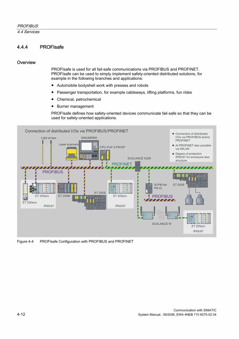
PROFIBUS 4.4 Services
Communication with SIMATIC 4-12 System Manual, 09/2006, EWA 4NEB 710 6075-02 04
4.4.4 PROFIsafe
Overview PROFIsafe is used for all fail-safe communications via PROFIBUS and PROFINET. PROFIsafe can be used to simply implement safety-oriented distributed solutions, for example in the following branches and applications: ● Automobile bodyshell work with presses and robots ● Passenger transportation, for example cableways, lifting platforms, fun rides ● Chemical, petrochemical ● Burner management PROFIsafe defines how safety-oriented devices communicate fail-safe so that they can be used for safety-oriented applications.
Figure 4-4 PROFIsafe Configuration with PROFIBUS and PROFINET
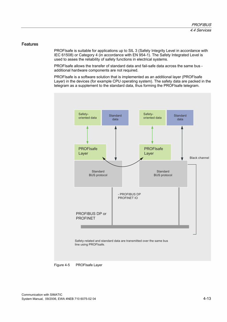
PROFIBUS 4.4 Services
Communication with SIMATIC System Manual, 09/2006, EWA 4NEB 710 6075-02 04 4-13
Features PROFIsafe is suitable for applications up to SIL 3 (Safety Integrity Level in accordance with IEC 61508) or Category 4 (in accordance with EN 954-1). The Safety Integrated Level is used to asses the reliability of safety functions in electrical systems. PROFIsafe allows the transfer of standard data and fail-safe data across the same bus - additional hardware components are not required. PROFIsafe is a software solution that is implemented as an additional layer (PROFIsafe Layer) in the devices (for example CPU operating system). The safety data are packed in the telegram as a supplement to the standard data, thus forming the PROFIsafe telegram.
Figure 4-5 PROFIsafe Layer

PROFIBUS 4.4 Services
Communication with SIMATIC 4-14 System Manual, 09/2006, EWA 4NEB 710 6075-02 04
PROFIsafe presents two alternative implementations: ● Solution with a bus line and a combined standard and safety-related controller ● Solution with separate transmission lines and separate controllers for standard and
safety-oriented automation PROFIsafe uses the following measures to ensure the data integrity for fail-safe transmissions: ● Sequential numbering of the safety telegrams. ● Time monitoring for telegrams and acknowledgement ● Identification between transmitter and receiver using a password ● Additional data security (Cyclic Redundancy Check)
Further Information PROFIsafe is specified in "PROFIsafe, Profile for Safety Technology". ● http://www.profibus.com/pb/profibus/safety/
Integration in STEP 7 With PROFIsafe, the fail-safe blocks in your user program are marked in yellow to correspond with the yellow that designates the physical fail-safe I/O modules.
4.4.5 PG/OP Communication Services
See also PG/OP Communication Services (Page 2-29)
4.4.6 S7 Communication Services
See also S7 Communication Services (Page 2-30)
PROFIBUS 4.4 Services
Communication with SIMATIC System Manual, 09/2006, EWA 4NEB 710 6075-02 04 4-15
4.4.7 PROFIBUS FMS Communication Services
Overview PROFIBUS FMS (Fieldbus Message Specification) allows the transfer of structured data (FMS variables) in order to facilitate open communication with field devices of various manufacturers. It is thus possible to implement not only motion control tasks, but also general control and measuring tasks.
Features PROFIBUS FMS is used to exchange data between programmable controllers of various manufacturers on one PROFIBUS subnet. The following FMS services are available to this purpose: ● READ ● WRITE ● INFORMATION REPORT With these FMS services the user program has read- and write-access to variables of the communication partner. Receipt of data is acknowledged by the partner, meaning that the application running on the distant communication partner has received the data correctly.
Integration in STEP 7 At SIMATIC S7 systems communication FBs are used for the FMS services. Data transmission and receipt is carried out by means of static connections. The corresponding FMS connections are configured with STEP 7 and are established when the S7 is started up. For PCs C functions within the framework of the SAPI-S7 interface and in OPC provide the FMS services.
4.4.8 PROFIBUS FDL Communication Services
Overview Fieldbus Data Link (FDL) offers services for the transferring data with acknowledgement on the PROFIBUS subnet.
Features The FDL service facilitates communication to any communication partner (for example, SIMATIC S5 or PC) that supports sending and receiving data in accordance with the SDA function. SDA means Send Data with Acknowledgement, meaning that the receipt of data is acknowledged by the FDL service of the communication partner. A SIMATIC NET CP card must be used for FDL.
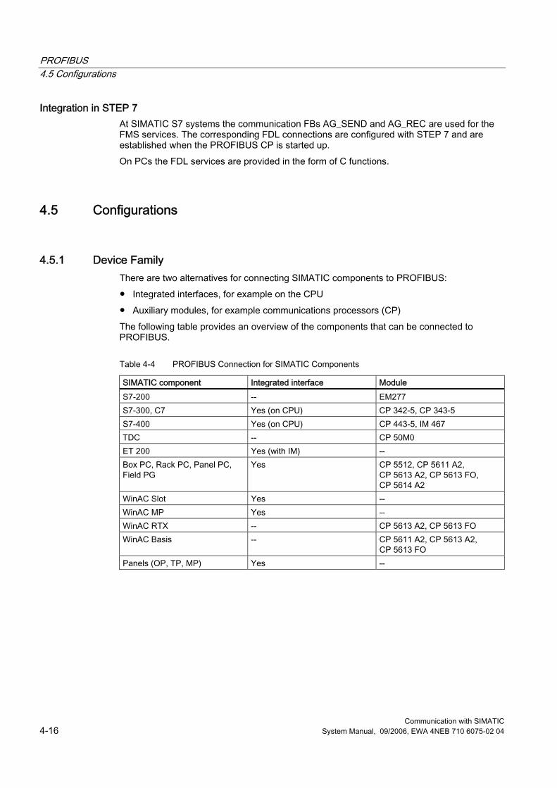
PROFIBUS 4.5 Configurations
Communication with SIMATIC 4-16 System Manual, 09/2006, EWA 4NEB 710 6075-02 04
Integration in STEP 7 At SIMATIC S7 systems the communication FBs AG_SEND and AG_REC are used for the FMS services. The corresponding FDL connections are configured with STEP 7 and are established when the PROFIBUS CP is started up. On PCs the FDL services are provided in the form of C functions.
4.5 Configurations
4.5.1 Device Family There are two alternatives for connecting SIMATIC components to PROFIBUS: ● Integrated interfaces, for example on the CPU ● Auxiliary modules, for example communications processors (CP) The following table provides an overview of the components that can be connected to PROFIBUS.
Table 4-4 PROFIBUS Connection for SIMATIC Components
SIMATIC component Integrated interface Module S7-200 -- EM277 S7-300, C7 Yes (on CPU) CP 342-5, CP 343-5 S7-400 Yes (on CPU) CP 443-5, IM 467 TDC -- CP 50M0 ET 200 Yes (with IM) -- Box PC, Rack PC, Panel PC, Field PG
Yes CP 5512, CP 5611 A2, CP 5613 A2, CP 5613 FO, CP 5614 A2
WinAC Slot Yes -- WinAC MP Yes -- WinAC RTX -- CP 5613 A2, CP 5613 FO WinAC Basis -- CP 5611 A2, CP 5613 A2,
CP 5613 FO Panels (OP, TP, MP) Yes --
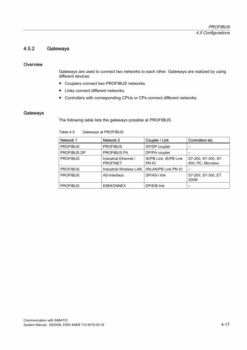
PROFIBUS 4.5 Configurations
Communication with SIMATIC System Manual, 09/2006, EWA 4NEB 710 6075-02 04 4-17
4.5.2 Gateways
Overview Gateways are used to connect two networks to each other. Gateways are realized by using different devices: ● Couplers connect two PROFIBUS networks. ● Links connect different networks. ● Controllers with corresponding CPUs or CPs connect different networks.
Gateways The following table lists the gateways possible at PROFIBUS.
Table 4-5 Gateways at PROFIBUS:
Network 1 Network 2 Coupler / Link Controllers etc. PROFIBUS PROFIBUS DP/DP coupler -- PROFIBUS DP PROFIBUS PA DP/PA coupler -- PROFIBUS Industrial Ethernet /
PROFINET IE/PB Link, IE/PB Link PN IO
S7-200, S7-300, S7-400, PC, Microbox
PROFIBUS Industrial Wireless LAN IWLAN/PB Link PN IO -- PROFIBUS AS-Interface DP/AS-I link S7-200, S7-300, ET
200M PROFIBUS EIB/KONNEX DP/EIB link --
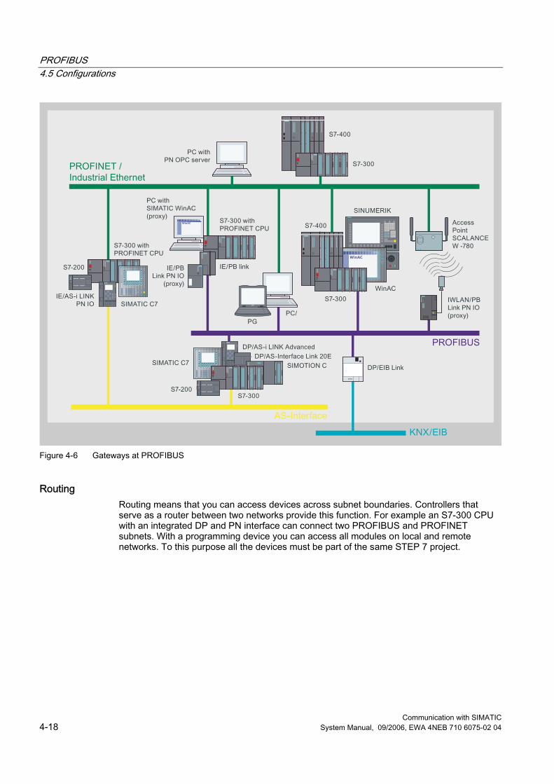
PROFIBUS 4.5 Configurations
Communication with SIMATIC 4-18 System Manual, 09/2006, EWA 4NEB 710 6075-02 04
Figure 4-6 Gateways at PROFIBUS
Routing Routing means that you can access devices across subnet boundaries. Controllers that serve as a router between two networks provide this function. For example an S7-300 CPU with an integrated DP and PN interface can connect two PROFIBUS and PROFINET subnets. With a programming device you can access all modules on local and remote networks. To this purpose all the devices must be part of the same STEP 7 project.
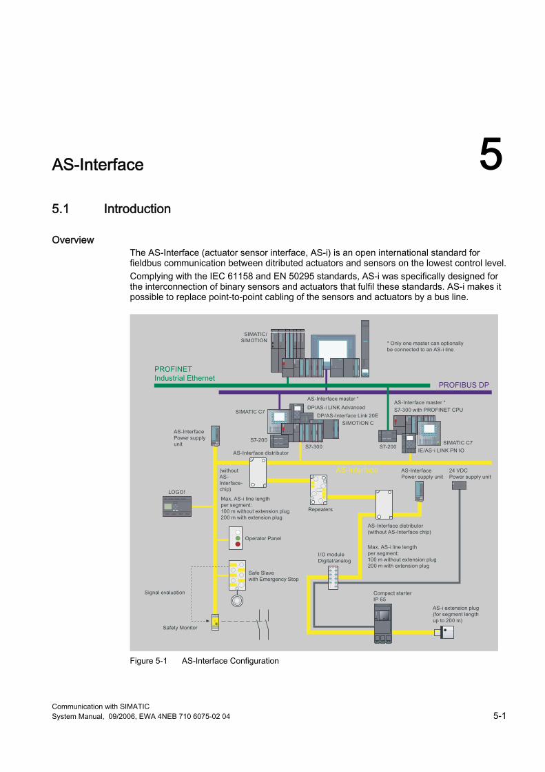
Communication with SIMATIC System Manual, 09/2006, EWA 4NEB 710 6075-02 04 5-1
AS-Interface 55.1 Introduction
Overview The AS-Interface (actuator sensor interface, AS-i) is an open international standard for fieldbus communication between ditributed actuators and sensors on the lowest control level. Complying with the IEC 61158 and EN 50295 standards, AS-i was specifically designed for the interconnection of binary sensors and actuators that fulfil these standards. AS-i makes it possible to replace point-to-point cabling of the sensors and actuators by a bus line.
Figure 5-1 AS-Interface Configuration
AS-Interface 5.2 Properties
Communication with SIMATIC 5-2 System Manual, 09/2006, EWA 4NEB 710 6075-02 04
The AS-Interface has the following advantages: ● Flexibility ● Cost effectiveness ● Simple and rapid installation with a minimum of errors ● A common line for transferring data and power
Further Information Brochure "Industrial communication for automation". ● Introductory information about industrial communication ● http://www.automation.siemens.com/net/html_76/ftp/presales/k-schrift_e.pdf Catalog IK PI "!ndustrial Communication for Automation and Drives", ● Device overview and ordering data for industrial communication ● http://www.automation.siemens.com/net/html_76/support/printkatalog.htm "AS-Interface - The Solution for Automation" Compendium. ● Compendium about technology, function and applications ● http://www.as-interface.net/System/Publications AS-Interface homepage: ● http://www.as-interface.net
5.2 Properties
5.2.1 Basic Principles The cable for an AS-i subnet handles both the data transmission and the distribution of auxiliary power to the sensors and actuators. AS-i subnets use an electrical bus. AS-i does not support optical or wireless networks. The AS-i master cyclically polls the AS-i slave devices to guarantee a pre-defined response time. All slaves have a unique address that is set by means of a specified address programming device. For fail-safe applications, ASIsafe supports the use of fail-safe devices on an AS-i subnet. The AS International Association certifies AS-i products. Tests ensure that devices of different manufacturers can communicate with each other at an AS-i subnet. The current AS-Interface standard is Specification 3.0.
AS-Interface 5.2 Properties
Communication with SIMATIC System Manual, 09/2006, EWA 4NEB 710 6075-02 04 5-3
5.2.2 Network Architectures AS-Interface allows the topologies line, tree and star. The length of the line may not exceed 100 m. You can connect the following to AS-i: ● Max. of 31 standard AS-i slaves or ● Max. of 62 AS-i slaves with extended addressing area A cycle time of 5 or 10 ms is reached. Analog slaves are special standard AS-i slaves that exchange analog data with the master by means of special profiles. AS-i slaves can be: ● Either sensors/actuators with an integrated AS- i connection ● Or AS- i modules Up to eight conventional binary sensors / actuators can be connected to each AS-i module.
5.2.3 Network Components An AS-i network consists of the following network components: ● Copper cable (usually yellow profiled flat cable) ● Repeaters and extenders for extending the AS-i line.
In addition repeaters isolate the two segments electrically from each other. ● AS-i power supply unit for supplying power to the sensors and actuators
5.2.4 Connection Systems Many sensors and actuators are connected to the AS-i line by means of the so-called penetration technique in which the contact mandrels of the device penetrate the insulation of the cable and establish a reliable contact. Sensors and actuators that do not have any AS-Interface connection can be connected to the bus via AS-i modules.
AS-Interface 5.3 Technologies
Communication with SIMATIC 5-4 System Manual, 09/2006, EWA 4NEB 710 6075-02 04
5.3 Technologies
5.3.1 Transmission Modes An unshielded 2-wire copper cable is used as the transmission medium at AS-i. At the same time it serves as the power supply (30 VDC) for the communication electronic equipment and for nodes with low power requirements such as light barriers. Loads with a high power requirement, such as valves, have a separate cable for the power supply (24 VDC). A special modulation procedure has been developed for the AS-Interface. The data that are to be transferred serially are modulated onto the power supply at a high frequency and insensitive to interefrence. Layers 1, 2 and 7 of the ISO-OSI reference model are implemented at AS-Interface.
5.3.2 Access Methods AS-Interface is designed as a single-master system with cyclic polling and serial tranmission protocol. The master of the AS-i network polls all the configured slaves at intervals that have been specified exactly. During this cyclic data transfer the master reads the inputs and writes the outputs of the slaves.
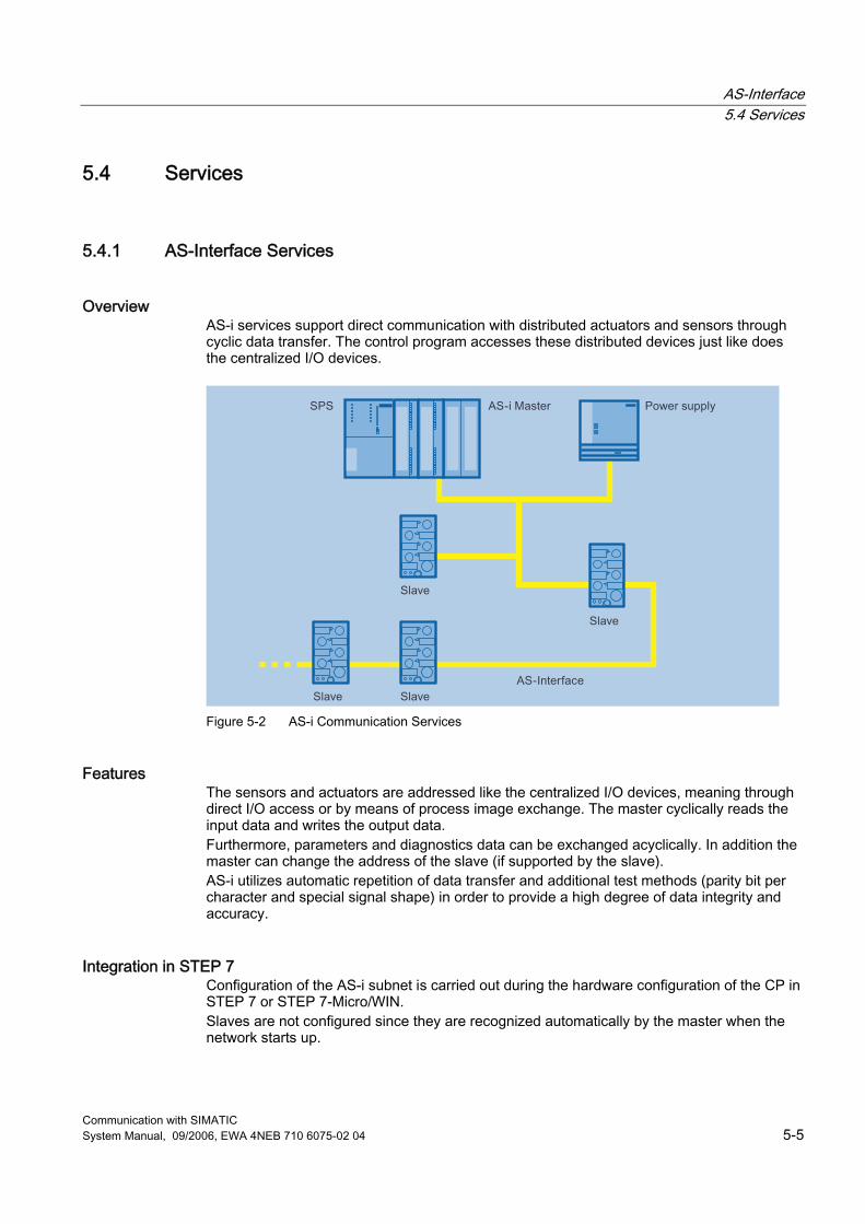
AS-Interface 5.4 Services
Communication with SIMATIC System Manual, 09/2006, EWA 4NEB 710 6075-02 04 5-5
5.4 Services
5.4.1 AS-Interface Services
Overview AS-i services support direct communication with distributed actuators and sensors through cyclic data transfer. The control program accesses these distributed devices just like does the centralized I/O devices.
Figure 5-2 AS-i Communication Services
Features The sensors and actuators are addressed like the centralized I/O devices, meaning through direct I/O access or by means of process image exchange. The master cyclically reads the input data and writes the output data. Furthermore, parameters and diagnostics data can be exchanged acyclically. In addition the master can change the address of the slave (if supported by the slave). AS-i utilizes automatic repetition of data transfer and additional test methods (parity bit per character and special signal shape) in order to provide a high degree of data integrity and accuracy.
Integration in STEP 7 Configuration of the AS-i subnet is carried out during the hardware configuration of the CP in STEP 7 or STEP 7-Micro/WIN. Slaves are not configured since they are recognized automatically by the master when the network starts up.
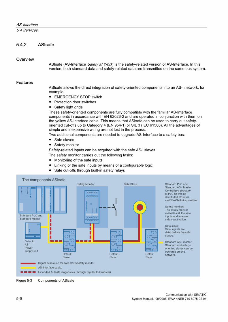
AS-Interface 5.4 Services
Communication with SIMATIC 5-6 System Manual, 09/2006, EWA 4NEB 710 6075-02 04
5.4.2 ASIsafe
Overview ASIsafe (AS-Interface Safety at Work) is the safety-related version of AS-Interface. In this version, both standard data and safety-related data are transmitted on the same bus system.
Features ASIsafe allows the direct integration of safety-oriented components into an AS-i network, for example: ● EMERGENCY STOP switch ● Protection door switches ● Safety light grids These safety-oriented components are fully compatible with the familiar AS-Interface components in accordance with EN 62026-2 and are operated in conjunction with them on the yellow AS-Interface cable. This means that ASIsafe can be used to carry out safety-oriented cut-offs up to Category 4 (EN 954-1) or SIL 3 (IEC 61508). All the advantages of simple and inexpensive wiring are not lost in the process. Two additional components are needed to upgrade AS-Interface to a safety bus: ● Safe slaves ● Safety monitor Safety-related inputs can be acquired with the safe AS-i slaves. The safety monitor carries out the following tasks: ● Monitoring of the safe inputs ● Linking of the safe inputs by means of a configurable logic ● Safe cut-offs through built-in safety relays
Figure 5-3 Components of ASisafe
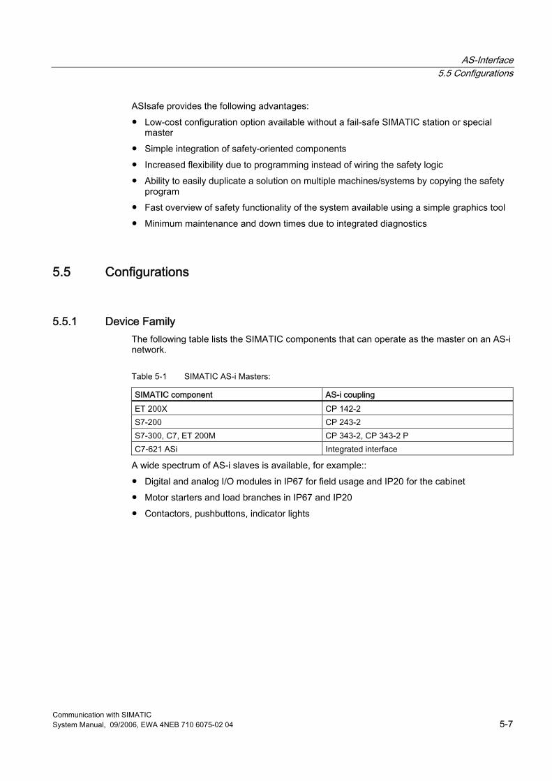
AS-Interface 5.5 Configurations
Communication with SIMATIC System Manual, 09/2006, EWA 4NEB 710 6075-02 04 5-7
ASIsafe provides the following advantages: ● Low-cost configuration option available without a fail-safe SIMATIC station or special
master ● Simple integration of safety-oriented components ● Increased flexibility due to programming instead of wiring the safety logic ● Ability to easily duplicate a solution on multiple machines/systems by copying the safety
program ● Fast overview of safety functionality of the system available using a simple graphics tool ● Minimum maintenance and down times due to integrated diagnostics
5.5 Configurations
5.5.1 Device Family The following table lists the SIMATIC components that can operate as the master on an AS-i network.
Table 5-1 SIMATIC AS-i Masters:
SIMATIC component AS-i coupling ET 200X CP 142-2 S7-200 CP 243-2 S7-300, C7, ET 200M CP 343-2, CP 343-2 P C7-621 ASi Integrated interface
A wide spectrum of AS-i slaves is available, for example:: ● Digital and analog I/O modules in IP67 for field usage and IP20 for the cabinet ● Motor starters and load branches in IP67 and IP20 ● Contactors, pushbuttons, indicator lights
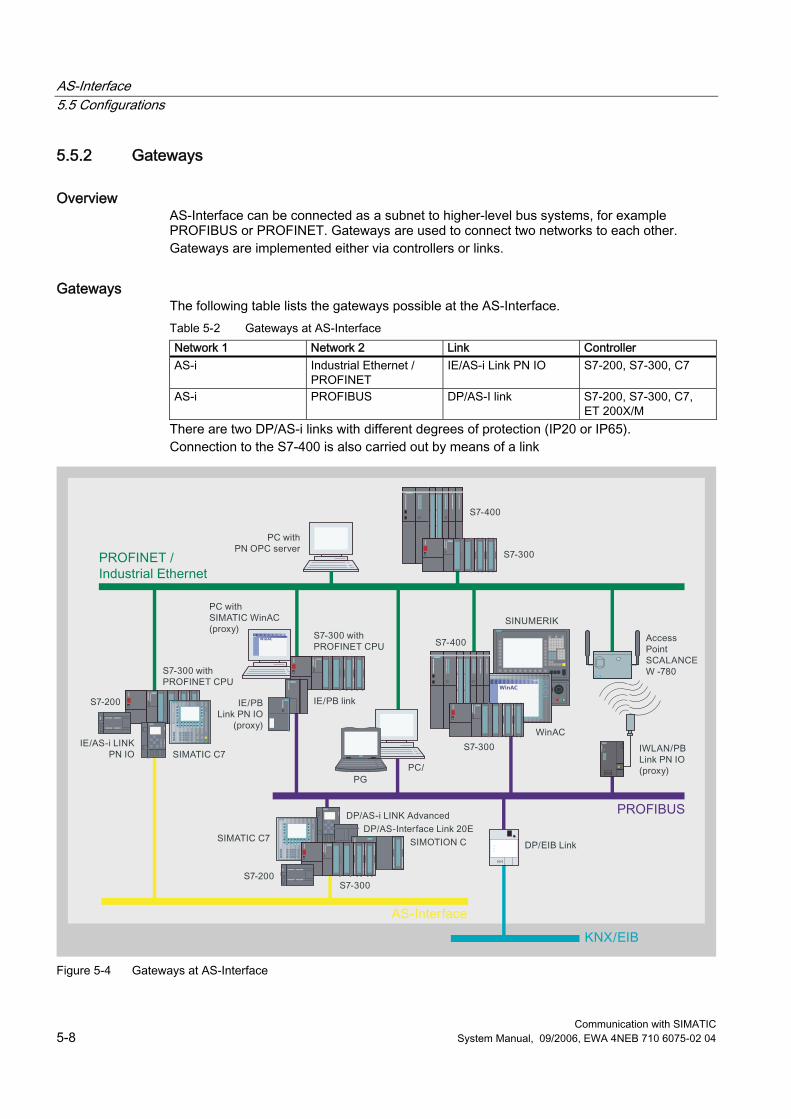
AS-Interface 5.5 Configurations
Communication with SIMATIC 5-8 System Manual, 09/2006, EWA 4NEB 710 6075-02 04
5.5.2 Gateways
Overview AS-Interface can be connected as a subnet to higher-level bus systems, for example PROFIBUS or PROFINET. Gateways are used to connect two networks to each other. Gateways are implemented either via controllers or links.
Gateways The following table lists the gateways possible at the AS-Interface. Table 5-2 Gateways at AS-Interface Network 1 Network 2 Link Controller AS-i Industrial Ethernet /
PROFINET IE/AS-i Link PN IO S7-200, S7-300, C7
AS-i PROFIBUS DP/AS-I link S7-200, S7-300, C7, ET 200X/M
There are two DP/AS-i links with different degrees of protection (IP20 or IP65). Connection to the S7-400 is also carried out by means of a link
Figure 5-4 Gateways at AS-Interface
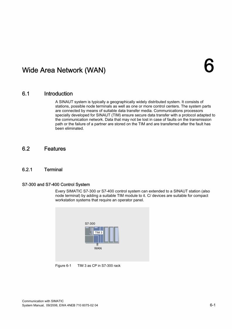
Communication with SIMATIC System Manual, 09/2006, EWA 4NEB 710 6075-02 04 6-1
Wide Area Network (WAN) 66.1 Introduction
A SINAUT system is typically a geographically widely distributed system. It consists of stations, possible node terminals as well as one or more control centers. The system parts are connected by means of suitable data transfer media. Communications processors specially developed for SINAUT (TIM) ensure secure data transfer with a protocol adapted to the communication network. Data that may not be lost in case of faults on the transmission path or the failure of a partner are stored on the TIM and are transferred after the fault has been eliminated.
6.2 Features
6.2.1 Terminal
S7-300 and S7-400 Control System Every SIMATIC S7-300 or S7-400 control system can extended to a SINAUT station (also node terminal) by adding a suitable TIM module to it. C/ devices are suitable for compact workstation systems that require an operator panel.
Figure 6-1 TIM 3 as CP in S7-300 rack
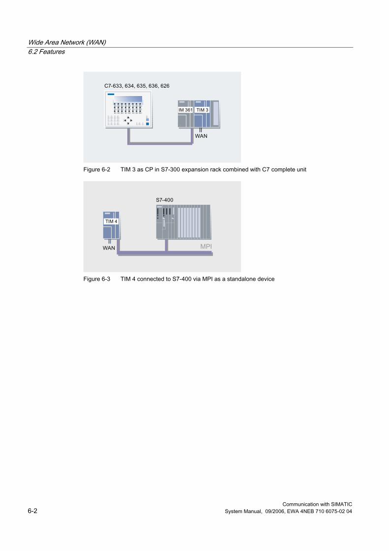
Wide Area Network (WAN) 6.2 Features
Communication with SIMATIC 6-2 System Manual, 09/2006, EWA 4NEB 710 6075-02 04
Figure 6-2 TIM 3 as CP in S7-300 expansion rack combined with C7 complete unit
Figure 6-3 TIM 4 connected to S7-400 via MPI as a standalone device
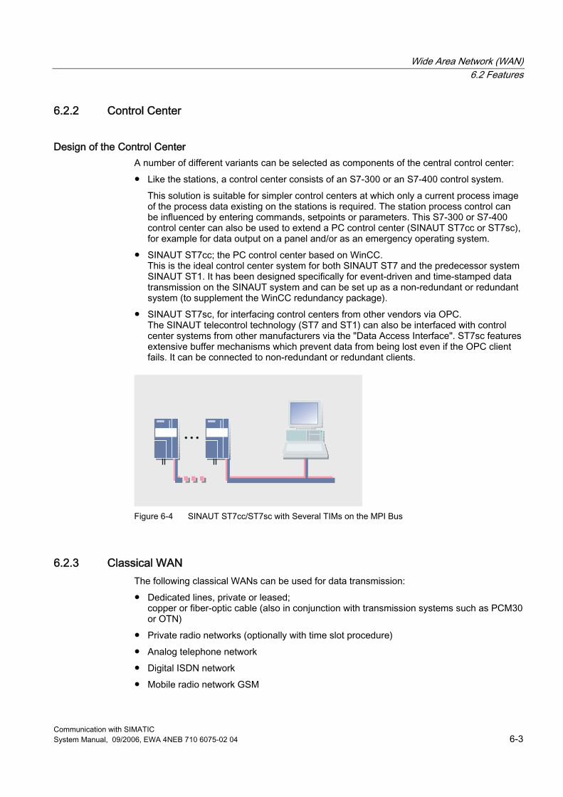
Wide Area Network (WAN) 6.2 Features
Communication with SIMATIC System Manual, 09/2006, EWA 4NEB 710 6075-02 04 6-3
6.2.2 Control Center
Design of the Control Center A number of different variants can be selected as components of the central control center: ● Like the stations, a control center consists of an S7-300 or an S7-400 control system.
This solution is suitable for simpler control centers at which only a current process image of the process data existing on the stations is required. The station process control can be influenced by entering commands, setpoints or parameters. This S7-300 or S7-400 control center can also be used to extend a PC control center (SINAUT ST7cc or ST7sc), for example for data output on a panel and/or as an emergency operating system.
● SINAUT ST7cc; the PC control center based on WinCC. This is the ideal control center system for both SINAUT ST7 and the predecessor system SINAUT ST1. It has been designed specifically for event-driven and time-stamped data transmission on the SINAUT system and can be set up as a non-redundant or redundant system (to supplement the WinCC redundancy package).
● SINAUT ST7sc, for interfacing control centers from other vendors via OPC. The SINAUT telecontrol technology (ST7 and ST1) can also be interfaced with control center systems from other manufacturers via the "Data Access Interface". ST7sc features extensive buffer mechanisms which prevent data from being lost even if the OPC client fails. It can be connected to non-redundant or redundant clients.
Figure 6-4 SINAUT ST7cc/ST7sc with Several TIMs on the MPI Bus
6.2.3 Classical WAN The following classical WANs can be used for data transmission: ● Dedicated lines, private or leased;
copper or fiber-optic cable (also in conjunction with transmission systems such as PCM30 or OTN)
● Private radio networks (optionally with time slot procedure) ● Analog telephone network ● Digital ISDN network ● Mobile radio network GSM
Wide Area Network (WAN) 6.2 Features
Communication with SIMATIC 6-4 System Manual, 09/2006, EWA 4NEB 710 6075-02 04
6.2.4 Ethernet-based WAN SINAUT communication via the Ethernet-based networks is possible between station and control center and also between individual stations: ● Via radio through use of special radio devices optimized for Ethernet, for example
SCALANCE W ● Via fiber-optic conductors, e.g. through use of SCALANCE X switches with optical ports;
distances of up to 26 km can then be covered ● Via public networks and the Internet using DSL or GPRS.
6.2.5 Transmssion on the Store-and-Forward Principle A simple connection between a station and the control center is not, as is common in SIMATIC communication, a direct connection between two partners in whichn one partner transmits and receives an acknowledgement of the proper receipt directly from the partner. This would not function at most WAN types as well as at the complex networks that are possible at SINAUT. At SINAUT a connection consists of several connection sections, whereby one TIM module takes over the role of a switching partner, meaning that it represents the respective end point of a section. A simple connection between the station and control center consists of three independent connections at SINAUT: ● From the station CPU to the station TIM ● From the station TIM to the central TIM ● From the central TIM to the control center PC SINAUT data transfer is carried out in accordance with the Store-and-Forward principle as follows: 1. The station CPU transfers the data to be sent to its station TIM and receives an
acknowledgement. The CPU then deletes the acknowledged data from its send buffer. 2. The station TIM saves these data temporarily and transfers them as soon as possible to
the central TIM. This acknowledges the receipt to the station TIM that then deletes the acknowledged data from its send buffer.
3. The central TIM also stores the data until these can be transferred to the control center PC and it has received a receipt acknowledgement from it. The central TIM then deletes the acknowledged data from its buffer memory.
The data storage duration at a TIM depends on the classification of the data to be transferred: ● Data that are recorded locally from the process in the station, typically status messages,
interrupts, analog process values, counter values, etc., are stored on the TIM until it was possible to send the data to the next instance in the SINAUT connection chain.
● Data that are to be transferred from the control, center to the process, typically commands, setpoint values, paramneters, etc., are only stored temporarily on the TIM until they could be transferred to the next instance in the network or until it is established that the end partner to whom the data are addressed cannot be reached.
Wide Area Network (WAN) 6.2 Features
Communication with SIMATIC System Manual, 09/2006, EWA 4NEB 710 6075-02 04 6-5
6.2.6 Change-Driven Data Transmission In the terminals, the SINAUT software ensures that process data is transmitted between the individual CPUs and the control center, e.g. ST7cc, in the event of changes. Connection, CPU or control center failures are displayed. A data update is performed automatically following debugging or after CPU or control center startup.
6.2.7 Date and Time An (optional) DCF77 radio clock can be used to supply the CPUs and the control center, e.g. ST7cc, with the date and time across the network. The systems therefore always have the exact time; switching over between summer (daylight saving) and winter (standard) times is carried out automatically. The GPS (Global Positioning System) can also be used as the time source instead of DCF77. This allows data telegrams to be sent with the original event moment. The user program can access the time, for example in order to start the programs depending on the time of day.
6.2.8 Local Data Storage A special property of the TIM communications module used in the SINAUT ST7 system is the capability for saving data which must not be lost in the event of a connection fault or if the partner fails. A memory capacity is provided for up to 32,000 telegrams. The memory capacity helps to save money on dial-up networks. Various priorities can be assigned to the data to be transmitted. At high priority, a dial-up connection is established immediately. At low priority, data are initially saved in the TIM. The data are transmitted the next time a connection is established with the partner for any reason. For example, if higher-priority information is to be transferred, or if a connection is established by the partner in order to exchange data. It is precisely because the TIM module can save data and transmit them at a later point in time with a time stamp that the use of a suitable control center system must be ensured. It must also be possible to continue to process these data, specifically as regards subsequent archiving, if the data are received in the control center delayed by a number of hours or even days. The SINAUT ST7cc control center system has been developed specially for these tasks.
6.2.9 SINAUT Remote Programming and Remote Diagnostics In industries in which SINAUT is used, the terminals are distributed across wide areas and are often situated in locations that are difficult to access. Faults which require a visit to be made to a terminal of this type are associated with long journeys. SINAUT ST7 therefore offers the possibility of remote programming and remote diagnostics through the WAN networkd configured in the SINAUT project. All diagnostics and programming functions provided by SIMATIC and SINAUT for station automation and WAN communication can be used via the WAN without interrupting the SINAUT data traffic. Programming device routing and data traffic share the available bandwidth on the transmission path. Programming device routing is simply allocated a higher priority.
Wide Area Network (WAN) 6.2 Features
Communication with SIMATIC 6-6 System Manual, 09/2006, EWA 4NEB 710 6075-02 04
6.2.10 Alarm Messaging via Text Message In order to alert standby service personnel, event-driven text messages can be sent to mobile phones from the CPUs. An acknowledgment that a message of this type has been received can be sent back to the sender CPU from the mobile phone. An SMS message can also be output as e-mail, fax or voice mail if the SMS provider offers these options.
6.2.11 Network Forms SINAUT ST7 supports the set-up of complete hierarchical control networks comprising terminals, node terminals and control center. Classical WANs as well as Ethernet-based networks can be used for information exchange between the individual devices. There are no restrictions in terms of network combinations in a project. Star, line and node structures can be set up, or even mixed configurations of these basic structures. A station can be linked using two transmission paths to permit redundant data transmission. The two paths can be of the same type or different, for example dedicated line, telephone network, ISDN or DSL (Also refer to the "Topologies" section below.)
6.2.12 Connection to Classical WAN The connection to a classicalWAN is made via the RS232 interface or the combined RS232/485 interface of the TIM through which various modems can be connected depending on the application: ● Dedicated line modems (for example MD2) for point-to-point, point-to-multipoint or linear
connections ● Radio sets from various manufacturers, also for company radiotelephone with time slot
procedure ● Analog dialing modems (for example MD3) for the analog telephone network or point-to-
point dedicated lines ● ISDN modems (for example MD4) as connection to the ISDN network ● GSM modems (for example GSM Kit MC45) as access to the mobile radio network Some TIM types already have a modem for a dedicated line, analog telephone network or ISDN on board. Connection of these compact units to the corresponding WAN is then carried out directly by means of the RJ12 port of the built-in modem.
6.2.13 Connection to Ethernet-Based WAN Some TIM types dispose of an RJ45 socket. These are suitable for connection to Ethernet-based networks with dedicated-line behavior. Depending on the application, different data communication equipment can be connected, such as: ● SCALANCE X switches for twisted pair cables or fiber-optic cables ● SCALANCE W (IWLAN) and Ethernet radio devices from various manufacturers ● DSL routers ● GPRS routers
Wide Area Network (WAN) 6.3 Protocols
Communication with SIMATIC System Manual, 09/2006, EWA 4NEB 710 6075-02 04 6-7
6.3 Protocols
6.3.1 SINAUT ST1 Protocol This protocol is used in the SINAUT ST1 system, which is based on the SIMATIC S5 system and is suitable for data transfer through a classical WAN. However, the SINAUT ST7 system also supports this protocol. The protocol can be used to further extend existing SINAUT ST1 systems or replace existing system parts with ST7 devices. Note: In SINAUT ST1 systems with SAMSY PC, LSC or CS7 control center systems, as well as in redundant ST1 configurations, the use of ST7 devices is only possible under certain conditions. Possible operating modes: ● Polling ● Polling with time-slot procedure ● Spontaneous mode (in dial-up networks) Please note that only modems suitable for 11-bit asynchronous characters may be used in both polling modes. However, "spontaneous" mode supports transmission with both 11-bit and 10-bit asynchronous characters.
6.3.2 SINAUT ST7 Protocol This protocol is a more advanced version of the ST1 protocol. It enables SINAUT communication via classical and Ethernet-based WAN. In addition, the addressing options have been extended: ● Up to 32000 stations can be addressed (as compared to a maximum of 254 with ST1) ● Telegrams contain a source and a target address, (ST1 telegrams only contain a source
or a target address). The ST7 protocol also supports "PG routing", i.e. remote programming and remote diagnostics via the WAN without the SINAUT data traffic being stopped. Programming device routing and data traffic share the available bandwidth on the transmission path. Programming device routing is simply allocated a higher priority. Possible operating modes in classical WAN: ● Polling, ● Polling with time-slot procedure, ● Multi-master polling with time-slot procedure ● Spontaneous mode (in dial-up networks) Please note that only modems suitable for 10-bit asynchronous characters may be used in "multi-master polling with time-slot procedure" mode. However, the other modes support transmission with both 11-bit and 10-bit asynchronous characters. Operating mode for Ethernet ● Spontaneous mode
Wide Area Network (WAN) 6.3 Protocols
Communication with SIMATIC 6-8 System Manual, 09/2006, EWA 4NEB 710 6075-02 04
6.3.3 Operating Modes The following description of the operating modes the terms "terminal", "node terminal" and "master (controller)" are used. In all these cases these refer to the TIM module that is operating in the respective function "terminal", "node terminal" or " master (controller)". Polling In polling mode, data exchange is controlled from the controller. It calls the connected terminals (including node terminals) in sequence. Terminals with modified data send these data as soon as they are called. Terminals with no modified data at the present time simply acknowledge the call. Data from the master (controller) to the terminals can be transferred at any time between the individual calls. The ST7 protocol supports data exchange broadcast between the terminals. During this type of communication, data is always exchanged via the polling controller. Polling with time-slot procedure Polling with time-slot procedure mode is used on a radio network on which the use of the radio frequency assigned by the registration authorities has to be shared with other operators. Typically, each operator has 6 seconds per minute to exchange data with its terminals. Once this time has elapsed, the frequency must be enabled for the next operator. During the assigned time slot this polling variant functions like normal polling. The ST7 protocol supports data exchange broadcast between the terminals. During this type of communication, data are always exchanged via the polling controller TIM.. In order that the time slot is observed exactly, the controller must be equipped with a DCF77 or GPS radio clock. Multi-master polling with time-slot procedure If terminals on the dedicated-line or radio network have to communicate with more than one control center, multi-master polling with time-slot procedure mode is used. Every minute, each of the connected controllers is allocated one or even a number of time slots for polling. During polling, the controllers take turns within one minute. This type of polling is similar to polling with time-slot procedure operating mode. However, in this mode, each station (including node stations) has a separate data buffer for each controller. Direct data transmission between the terminals is possible. During this type of communication, data is always exchanged via the polling controller. As a number of controllers are present, data exchange broadcast between substations can be set up with redundancy: If the priority controller fails, the alternative controller will take over data exchange broadcast. In this operating mode every controller also must be equipped with a DCF77 or GPS radio clock in order that the time slot is observed exactly. Spontaneous mode for data exchange on dial-up networks Different priorities (high, normal or alarm) can be assigned to the data of the station or node station for transmission in the dial-up network. Data to be sent by the control center always have the high priority. If data with a high or alarm priority are pending for transmission, a dial-up connection is established immediately. At normal priority, data are initially saved in the terminals. They are transmitted the next time a connection is established with the partner for any reason. For example, if information with a high or alarm priority is to be transferred, or if a connection is established by the partner in order to exchange data. The telegrams saved in the TIM are transmitted according to the FIFO principle, i.e. in the original chronological sequence, providing they are telegrams with high or normal priority. If alarm telegrams are present in the TIM buffer, these are always transmitted before the other telegrams. Data exchange broadcast between terminals is possible with the ST7 protocol.
Wide Area Network (WAN) 6.3 Protocols
Communication with SIMATIC System Manual, 09/2006, EWA 4NEB 710 6075-02 04 6-9
Spontaneous mode for free-of-charge Ethernet When sending data through a free-of-charge Ethernet, these are immediately transferred to the respective partner irrespective of priority. The transmission sequence is according to the FIFO principle. This does not apply to telegrams with maximum priority. These are transmitted prior to any other telegrams still present in the buffer. Transmission is carried out using the S7 communications functions. A permanent S7 connection is established in each case for transmission between two Ethernet TIMs or between an Ethernet TIM and ST7cc/ST7sc. The two TIMs or the TIM and ST7cc/ST7sc exchange the data packages specific to SINAUT ST7 with application of the TCP/IP transport protocol. Data exchange broadcast between the terminals directly from terminal to terminal is possible, as usual with Ethernet. Spontaneous mode for charged Ethernet Different priorities (high, normal or alarm) can be assigned to the data of the terminal or node terminal for charged Ethernet, for example GPRS, as in a dial-up network. If data with a high or alarm priority are pending for transmission, these are transmitted immediately. At normal priority, data are initially saved in the TIM. The data are transmitted under the following conditions: ● If data with a high or alarm priority arrive ● If the amount of stored data reaches or exceeds a specific limit ● If a configurable period expires without one of the previous criteria having caused
transmission of the stored data. Transmission is carried out using the S7 communications functions here as well. Direct data transmission between the terminals is possible. However, it depends on the network whether this is possible directly from terminal to terminals or whether such connections have to be routed through the controller TIM. The latter is the case, for example, for GPRS connections.

Wide Area Network (WAN) 6.3 Protocols
Communication with SIMATIC 6-10 System Manual, 09/2006, EWA 4NEB 710 6075-02 04
6.3.4 Function of the TIM The TIM can operate in "terminal", "node terminal" and "master (controller)" mode in classical WAN. In the case of Ethernet-based networks this depends on the type. This classification normally does not exist, meaning that all the partners are equal. However, in a GPRS network the classification by "terminal", "node terminal" and "master (controller)" have to be used. The TIM manages data traffic via the connected WAN independently. For this purpose, the module has its own processor and a RAM to buffer up to 32.000 data messages when the communication link is faulty or a partner fails and to reduce connection costs in the dial-up network. Two alternatives are available for the CPU and TIM for reading and writing the data to be sent or received: ● Use of the SINAUT TD7 software for the CPU (TD7onCPU):
The SINAUT program in the CPU, configured with blocks from the SINAUT TD7 library, acquires the process data to be transferred, checks them for changes and then forwards them to the TIM for transmission via the WAN. Telegrams received without faults by the TIM via the WAN are forwarded to the local CPU. A block integrated in the CPU responsible for evaluating the telegrams concerned outputs the information received to the outputs or data areas configured on the block.
● Use of the Software SINAUT TD7 integrated in the TIM (TD7 on TIM): The TD7onTIM program configured by the user directly reads the process data to be transferred from the memory areas of the CPU located in the S7-300 rack (inputs, bit memories, DBs), checks them for changes, and then forwards them to the TIM's send buffer for transmission via the WAN or Ethernet. Data from telegrams received without fault by the TIM via the WAN are directly written by the TIM into the configured memory areas of the CPU.
The data acquired by "TD7onCPU" or "TD7onTIM" can be optionally assigned a time stamp, and also a "normal" or "high" priority ID for transmission via a dial-up network. "TD7onTIM" additionally permits identification of very important data as "maximum priority". These data have priority over all other data present in the send buffer, i.e. they are transferred first. The TIM stores the data to be transferred in its RAM buffer. The manner in which the TIM subsequently sends these data depends on the respective transmission network:
Wide Area Network (WAN) 6.3 Protocols
Communication with SIMATIC System Manual, 09/2006, EWA 4NEB 710 6075-02 04 6-11
Transfer via a classical WAN The manner in which the TIM sends these data depends on the type of WAN and the TIM function selected: ● Dedicated line, radio network
In "terminal" or "node terminal" mode, the TIM waits to be polled by the controller. The stored data telegrams are then transferred. If no telegrams are available, the poll is only acknowledged. In "controller" mode, after each poll + reply has been completed, the TIM sends one of the messages stored in its buffer (default setting). If a larger number of telegrams is to be exchanged between two polls, this can be defined when configuring the TIM.
● Dial-up network For data with "normal" priority, the TIM is not active initially in "terminal" or "node terminal" mode. However, for data with "high" or "maximum" priority, the TIM will immediately attempt to establish a connection with the addressed partner in order to start data transmission. If the TIM buffer contains data with "normal" priority at this point, they are also transferred. Data with "maximum" priority are always transferred first. Subsequently the data with the priority "high" and "normal" are transferred in accordance with the FIFO principle, meaning irrespective of the respective priority. In the "master (controller)" function the TIM will always try to establish a connection with the addressed partner and to transfer the data, irrespective of any priority.
Either the SINAUT ST7 or the SINAUT ST1 protocol can be used for data traffic on a classical WAN. The operating mode used depends on the type of WAN: ● In the case of a dedicated line and a radio network, data exchange is usually carried out
in the "Polling operating mode. In the case of several controllers in the mode "Multi-master polling with time-slot procedure" (not possible for SINAUT ST1). In the case of a radio network the operating mode "Polling with time-slot procedure" can be selected. In both operating modes with time-slot procedure a TIM can always be used in the function "terminal" or "node terminal". In order to function as a "master (controller)" the TIM must have a DCF77 radio clock receiver on board.
● On dial-up networks, data exchange always takes place in "Spontaneous" mode. Transfer via an Ethernet-Based WAN The transmission behavior depends on which the network is a charged network (for example GPRS) or not. The correspondingly required spontaneous operating mode (immediate or cost-optimized transmission) can be set for the corresponding WAN port of the TIM.
Wide Area Network (WAN) 6.4 Topologies
Communication with SIMATIC 6-12 System Manual, 09/2006, EWA 4NEB 710 6075-02 04
6.4 Topologies
6.4.1 Introduction The overview below outlines the network configurations which can be implemented with SINAUT in the WAN. The protocols and operating modes which can be used by SINAUT for communication via each network are indicated for each network configuration. The symbols used describe the function of the WAN port on a TIM module. A TIM 3 module has one or two WAN ports, depending on its type. A TIM 4 has two WAN ports. The two ports on a TIME 3 or TIM 4 can exercise the same functions (e.g. 2 x controller) or different functions (e.g. node + controller). On redundant WAN connections, a TIM with two ports must always be used, as redundant paths always start and end on a TIM module.

Wide Area Network (WAN) 6.4 Topologies
Communication with SIMATIC System Manual, 09/2006, EWA 4NEB 710 6075-02 04 6-13
6.4.2 Configuration Examples
Figure 6-5 Dedicated Line Configurations
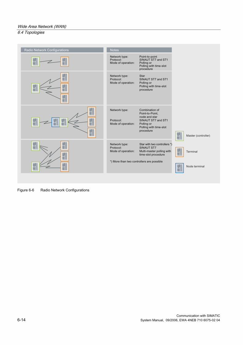
Wide Area Network (WAN) 6.4 Topologies
Communication with SIMATIC 6-14 System Manual, 09/2006, EWA 4NEB 710 6075-02 04
Figure 6-6 Radio Network Configurations
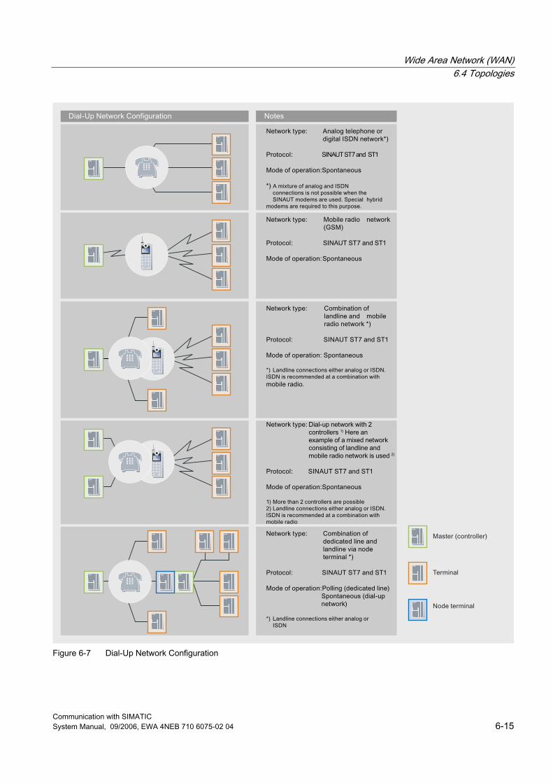
Wide Area Network (WAN) 6.4 Topologies
Communication with SIMATIC System Manual, 09/2006, EWA 4NEB 710 6075-02 04 6-15
Figure 6-7 Dial-Up Network Configuration
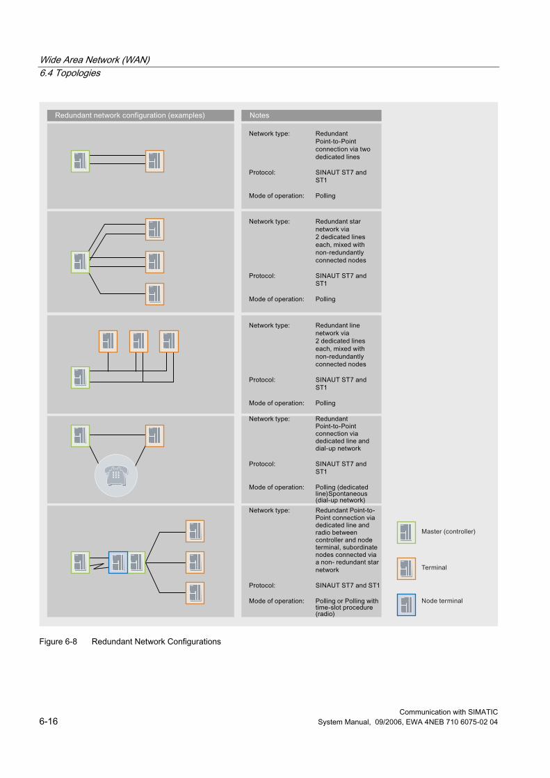
Wide Area Network (WAN) 6.4 Topologies
Communication with SIMATIC 6-16 System Manual, 09/2006, EWA 4NEB 710 6075-02 04
Figure 6-8 Redundant Network Configurations
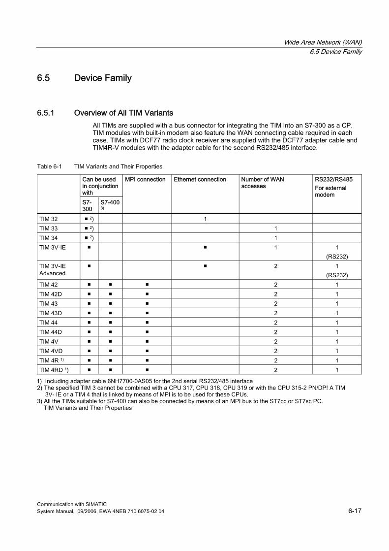
Wide Area Network (WAN) 6.5 Device Family
Communication with SIMATIC System Manual, 09/2006, EWA 4NEB 710 6075-02 04 6-17
6.5 Device Family
6.5.1 Overview of All TIM Variants All TIMs are supplied with a bus connector for integrating the TIM into an S7-300 as a CP. TIM modules with built-in modem also feature the WAN connecting cable required in each case. TIMs with DCF77 radio clock receiver are supplied with the DCF77 adapter cable and TIM4R-V modules with the adapter cable for the second RS232/485 interface.
Table 6-1 TIM Variants and Their Properties
Can be used in conjunction with
S7-300
S7-400 3)
MPI connection Ethernet connection Number of WAN accesses
RS232/RS485 For external modem
TIM 32 ■ 2) 1 TIM 33 ■ 2) 1 TIM 34 ■ 2) 1 TIM 3V-IE ■ ■ 1 1
(RS232) TIM 3V-IE Advanced
■ ■ 2 1 (RS232)
TIM 42 ■ ■ ■ 2 1 TIM 42D ■ ■ ■ 2 1 TIM 43 ■ ■ ■ 2 1 TIM 43D ■ ■ ■ 2 1 TIM 44 ■ ■ ■ 2 1 TIM 44D ■ ■ ■ 2 1 TIM 4V ■ ■ ■ 2 1 TIM 4VD ■ ■ ■ 2 1 TIM 4R 1) ■ ■ ■ 2 1 TIM 4RD 1) ■ ■ ■ 2 1
1) Including adapter cable 6NH7700-0AS05 for the 2nd serial RS232/485 interface 2) The specified TIM 3 cannot be combined with a CPU 317, CPU 318, CPU 319 or with the CPU 315-2 PN/DP! A TIM 3V- IE or a TIM 4 that is linked by means of MPI is to be used for these CPUs. 3) All the TIMs suitable for S7-400 can also be connected by means of an MPI bus to the ST7cc or ST7sc PC. TIM Variants and Their Properties
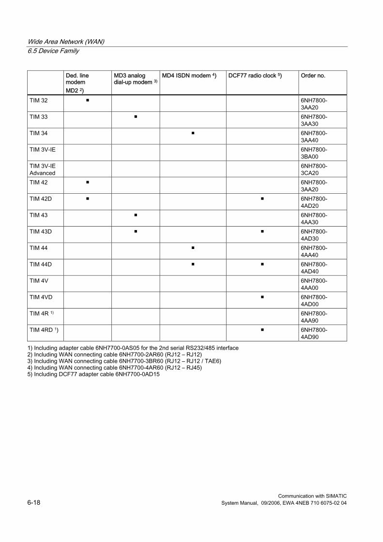
Wide Area Network (WAN) 6.5 Device Family
Communication with SIMATIC 6-18 System Manual, 09/2006, EWA 4NEB 710 6075-02 04
Ded. line modem MD2 2)
MD3 analog dial-up modem 3)
MD4 ISDN modem 4) DCF77 radio clock 5) Order no.
TIM 32 ■ 6NH7800-3AA20
TIM 33 ■ 6NH7800-3AA30
TIM 34 ■ 6NH7800-3AA40
TIM 3V-IE 6NH7800-3BA00
TIM 3V-IE Advanced
6NH7800-3CA20
TIM 42 ■ 6NH7800-3AA20
TIM 42D ■ ■ 6NH7800-4AD20
TIM 43 ■ 6NH7800-4AA30
TIM 43D ■ ■ 6NH7800-4AD30
TIM 44 ■ 6NH7800-4AA40
TIM 44D ■ ■ 6NH7800-4AD40
TIM 4V 6NH7800-4AA00
TIM 4VD ■ 6NH7800-4AD00
TIM 4R 1) 6NH7800-4AA90
TIM 4RD 1) ■ 6NH7800-4AD90
1) Including adapter cable 6NH7700-0AS05 for the 2nd serial RS232/485 interface 2) Including WAN connecting cable 6NH7700-2AR60 (RJ12 – RJ12) 3) Including WAN connecting cable 6NH7700-3BR60 (RJ12 – RJ12 / TAE6) 4) Including WAN connecting cable 6NH7700-4AR60 (RJ12 – RJ45) 5) Including DCF77 adapter cable 6NH7700-0AD15
Communication with SIMATIC System Manual, 09/2006, EWA 4NEB 710 6075-02 04 7-1
Multi-Point Interface (MPI) 77.1 Introduction
MPI (Multi-Point Interface) is the integrated interface for SIMATIC products: ● Controllers ● Panels ● Programming devices/PCs With MPI shall subnets with the following properties are established: ● Small scope ● Few nodes ● Small amounts of data
7.2 Properties
7.2.1 Basic Principles MPI provides a simple network capability with the following services: ● PG/OP communication ● S7 communication ● S7 basic communication ● Global Data Communication (GD) MPI supports baud rates of 187.5 kbps to 12 Mbps. The addresses of the MPI nodes must be unique and are set with the programming device PC.
Multi-Point Interface (MPI) 7.3 Technologies
Communication with SIMATIC 7-2 System Manual, 09/2006, EWA 4NEB 710 6075-02 04
7.2.2 Network Architectures MPI is based on the PROFIBUS standard (IEC 61158 and EN 50170) and supports the following bus topologies: ● Line ● Star ● Tree An MPI subnet encompasses 127 nodes and consists of several segments. A segment encompasses a maximum of 32 nodes and is limited by terminating resistors. Segments are coupled by repeaters. The max. line length without repeaters amounts to 50 m.
7.2.3 Network Components The following network components are used at MPI: ● PROFIBUS bus line for bulding up the network ● Repeater RS 485 for coupling segments
7.2.4 Connection Systems The nodes are connected to the MPI network as follows: ● Programming devices/PCs and panels are coupled by means of connecting cables. ● The PROFIBUS bus line is connected by means of a bus connector to the MPI interface
of the CPUs of the controllers.
7.3 Technologies
7.3.1 Transmission Methods MPI uses the electrical standard transmission medium RS 485 that is also used by PROFIBUS. However, an MPI network can also be connected to optical PROFIBUS networks by means of the PROFIBUS OLM (Optical Link Module).
7.3.2 Access Methods The access method used at MPI depends on the service used, for example PROFIBUS DP.
Multi-Point Interface (MPI) 7.4 Services
Communication with SIMATIC System Manual, 09/2006, EWA 4NEB 710 6075-02 04 7-3
7.4 Services
7.4.1 PG/OP Communication Services
See also PG/OP Communication Services (Page 2-29)
7.4.2 S7 Communication Services
See also S7 Communication Services (Page 2-30)
7.4.3 S7 Basic Communication Services
Overview S7 basic communication allow the exchange of data for non-configured S7 connections in an MPI subnet. System functions (SFCs) are used to this purpose.
Features These SFCs perform the following tasks: ● Reading and writing access to data in the SIMATIC S7 and C7 controllers ● Transferring small amounts of data through an MPI subnet to another S7 station
(S7 controller, panel or PC) The maximum amount of data that can be transferred is 76 bytes. Communication with stations in other subnets is not possible with the SFCs for S7 basic communication. Modules can be addressed in the local station or in the MPI subnet: ● SFCs for exchanging data between an S7 CPU and other modules with communication
functionality, if the communication partners belong to the same S7 station. These SFCs are identified by a preceding "I" for internal. – I_GET (SFC 72) – I_PUT (SFC 73)
● SFCs for echanging data between an S7 CPU and other modules with communication functionality, if the communication partners are connected to a common MPI subnet. These SFCs are identified by a preceding "X" for external. – X_SEND (SFC 65) – X_RCV (SFC 66) – X_GET (SFC 67) – X_PUT (SFC 68)
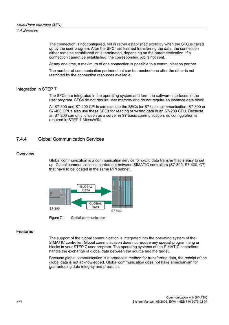
Multi-Point Interface (MPI) 7.4 Services
Communication with SIMATIC 7-4 System Manual, 09/2006, EWA 4NEB 710 6075-02 04
The connection is not configured, but is rather established explicitly when the SFC is called up by the user program. After the SFC has finished transferring the data, the connection either remains established or is terminated, depending on the parameterization. If a connection cannot be established, the corresponding job is not sent. At any one time, a maximum of one connection is possible to a communication partner. The number of communication partners that can be reached one after the other is not restricted by the connection resources available.
Integration in STEP 7 The SFCs are integrated in the operating system and form the software interfaces to the user program. SFCs do not require user memory and do not require an instance data block. All S7-300 and S7-400 CPUs can execute the SFCs for S7 basic communication. S7-300 or S7-400 CPUs also use these SFCs for reading or writing data in an S7-200 CPU. Because an S7-200 can only function as a server in S7 basic communication, no configuration is required in STEP 7 Micro/WIN.
7.4.4 Global Communication Services
Overview Global communication is a communication service for cyclic data transfer that is easy to set up. Global communication is carried out between SIMATIC controllers (S7-300, S7-400, C7) that have to be located in the same MPI subnet.
Figure 7-1 Global communication
Features The support of the global communication is integrated into the operating system of the SIMATIC controller. Global communication does not require any special programming or blocks in your STEP 7 user program. The operating systems of the SIMATIC controllers handle the exchange of global data between the source and the target. Because global communication is a broadcast method for transferring data, the receipt of the global data is not acknowledged. Global communication does not have amechanism for guaranteeing data integrity and precision.
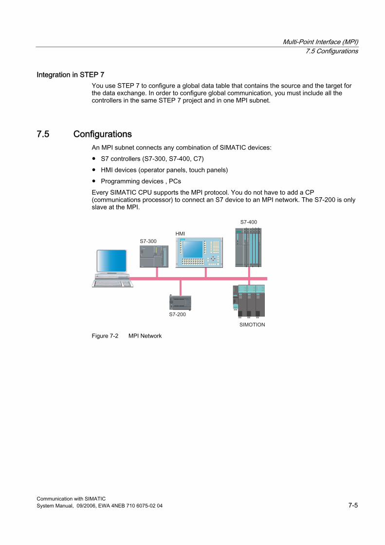
Multi-Point Interface (MPI) 7.5 Configurations
Communication with SIMATIC System Manual, 09/2006, EWA 4NEB 710 6075-02 04 7-5
Integration in STEP 7 You use STEP 7 to configure a global data table that contains the source and the target for the data exchange. In order to configure global communication, you must include all the controllers in the same STEP 7 project and in one MPI subnet.
7.5 Configurations An MPI subnet connects any combination of SIMATIC devices: ● S7 controllers (S7-300, S7-400, C7) ● HMI devices (operator panels, touch panels) ● Programming devices , PCs Every SIMATIC CPU supports the MPI protocol. You do not have to add a CP (communications processor) to connect an S7 device to an MPI network. The S7-200 is only slave at the MPI.
s
Figure 7-2 MPI Network

Multi-Point Interface (MPI) 7.5 Configurations
Communication with SIMATIC 7-6 System Manual, 09/2006, EWA 4NEB 710 6075-02 04
Communication with SIMATIC System Manual, 09/2006, EWA 4NEB 710 6075-02 04 8-1
Point-to-Point Interface (PPI) 88.1 Introduction
PPI (Point-to-Point Interface) is an integrated interface that was developed specially for the SIMATIC S7-200. A PPI network typically connects S7-200 devices. However, other SIMATIC S7 controllers (such as S7-300 and S7-400) or operator panels can communicate with an S7-200 in the PPI network.
8.2 Features
8.2.1 Basic Principles PPI is a master-slave protocol in which the master devices send requests to slave devices. Slave devices do not initiate messages, but wait until a master device sends a request or polls for a response. Communication is carried out by means of a commonly used PPI connection. Master devices are, for example: ● Programming device with STEP 7 Micro/WIN ● HMI devices (touch panels, text displays or operator panels) Slave devices are, for example: ● S7-200 CPUs ● Expansion racks (for example EM 277) S7-200 CPUs can also be activated as PPI masters through programming.

Point-to-Point Interface (PPI) 8.3 Technologies
Communication with SIMATIC 8-2 System Manual, 09/2006, EWA 4NEB 710 6075-02 04
8.2.2 Network Architectures PPI is based on the PROFIBUS standard (IEC 61158 and EN 50170) and supports the following bus topologies: ● Line ● Star With PPI multi-master networks with a maximum of 32 masters are built up: ● The number of masters that can communicate with any slave is not limited. ● An slave can be assigned to masters. The PPI network can be extended by using the RS-485 repeater. Modems can also be connected to the PPI network.
8.2.3 Network Components The PPI multi-master cable.is used to build up the PPI network.
8.2.4 Connection Systems The PPI multi-master cable is connected to the devices by means of plug connectors.
8.3 Technologies
8.3.1 Transmission Methods PPI is an asynchronous character-based protocol. Data transfer is carried out through the RS 232 or USB interface. The data transfer rate lies between 1.2 kbps and 115.2 kbps.
8.3.2 Access Methods Like PROFIBUS PPI also uses the Token passing procedure for the bus access.
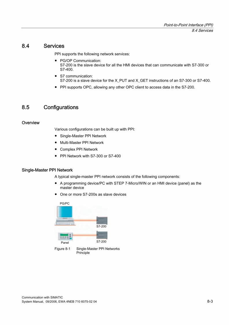
Point-to-Point Interface (PPI) 8.4 Services
Communication with SIMATIC System Manual, 09/2006, EWA 4NEB 710 6075-02 04 8-3
8.4 Services PPI supports the following network services: ● PG/OP Communication:
S7-200 is the slave device for all the HMI devices that can communicate with S7-300 or S7-400.
● S7 communication: S7-200 is a slave device for the X_PUT and X_GET instructions of an S7-300 or S7-400.
● PPI supports OPC, allowing any other OPC client to access data in the S7-200.
8.5 Configurations
Overview Various configurations can be built up with PPI: ● Single-Master PPI Network ● Multi-Master PPI Network ● Complex PPI Network ● PPI Network with S7-300 or S7-400
Single-Master PPI Network A typical single-master PPI network consists of the following components: ● A programming device/PC with STEP 7-Micro/WIN or an HMI device (panel) as the
master device ● One or more S7-200s as slave devices
Figure 8-1 Single-Master PPI Networks
Principle
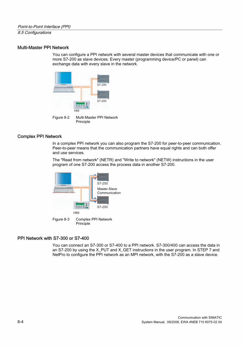
Point-to-Point Interface (PPI) 8.5 Configurations
Communication with SIMATIC 8-4 System Manual, 09/2006, EWA 4NEB 710 6075-02 04
Multi-Master PPI Network You can configure a PPI network with several master devices that communicate with one or more S7-200 as slave devices. Every master (programming device/PC or panel) can exchange data with every slave in the network.
Figure 8-2 Multi-Master PPI Network
Principle
Complex PPI Network In a complex PPI network you can also program the S7-200 for peer-to-peer communication. Peer-to-peer means that the communication partners have equal rights and can both offer and use services. The "Read from network" (NETR) and "Write to network" (NETW) instructions in the user program of one S7-200 access the process data in another S7-200.
Figure 8-3 Complex PPI Network
Principle
PPI Network with S7-300 or S7-400 You can connect an S7-300 or S7-400 to a PPI network. S7-300/400 can access the data in an S7-200 by using the X_PUT and X_GET instructions in the user program. In STEP 7 and NetPro to configure the PPI network as an MPI network, with the S7-200 as a slave device.
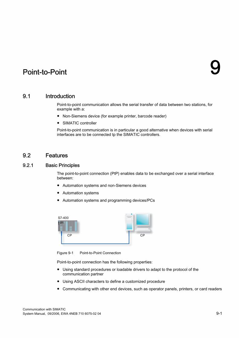
Communication with SIMATIC System Manual, 09/2006, EWA 4NEB 710 6075-02 04 9-1
Point-to-Point 99.1 Introduction
Point-to-point communication allows the serial transfer of data between two stations, for example with a: ● Non-Siemens device (for example printer, barcode reader) ● SIMATIC controller Point-to-point communication is in particular a good alternative when devices with serial interfaces are to be connected tp the SIMATIC controllers.
9.2 Features 9.2.1 Basic Principles
The point-to-point connection (PtP) enables data to be exchanged over a serial interface between:
● Automation systems and non-Siemens devices
● Automation systems
● Automation systems and programming devices/PCs
Figure 9-1 Point-to-Point Connection
Point-to-point connection has the following properties:
● Using standard procedures or loadable drivers to adapt to the protocol of the communication partner
● Using ASCII characters to define a customized procedure
● Communicating with other end devices, such as operator panels, printers, or card readers
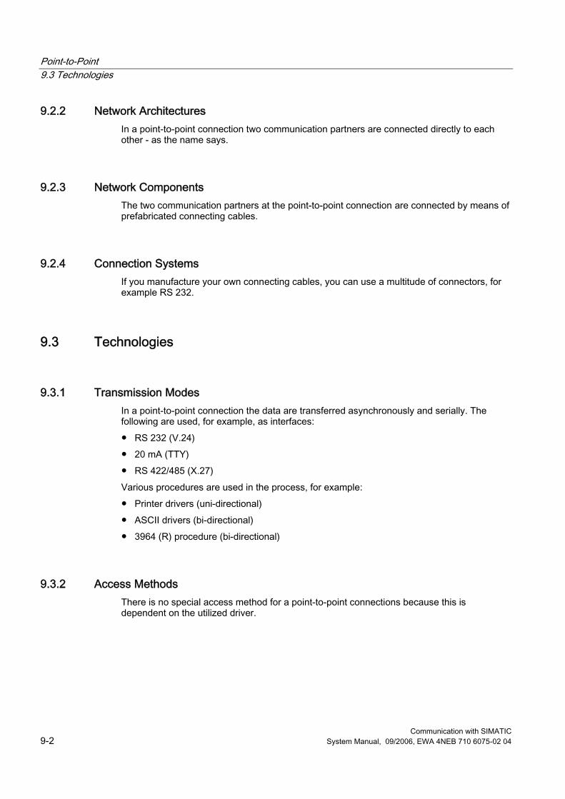
Point-to-Point 9.3 Technologies
Communication with SIMATIC 9-2 System Manual, 09/2006, EWA 4NEB 710 6075-02 04
9.2.2 Network Architectures In a point-to-point connection two communication partners are connected directly to each other - as the name says.
9.2.3 Network Components The two communication partners at the point-to-point connection are connected by means of prefabricated connecting cables.
9.2.4 Connection Systems If you manufacture your own connecting cables, you can use a multitude of connectors, for example RS 232.
9.3 Technologies
9.3.1 Transmission Modes In a point-to-point connection the data are transferred asynchronously and serially. The following are used, for example, as interfaces: ● RS 232 (V.24) ● 20 mA (TTY) ● RS 422/485 (X.27) Various procedures are used in the process, for example: ● Printer drivers (uni-directional) ● ASCII drivers (bi-directional) ● 3964 (R) procedure (bi-directional)
9.3.2 Access Methods There is no special access method for a point-to-point connections because this is dependent on the utilized driver.

Communication with SIMATIC System Manual, 09/2006, EWA 4NEB 710 6075-02 04 10-1
KNX/EIB (KONNEX) 1010.1 Introduction
Overview The EIB (European Installation Bus) is now commonly used in Europe in building systems. EIB is supported by many representatives of the electrical and building services automation sector who have come together under the auspices of the European Installation Bus Association (EIBA) . A defined standard interface allows products from different manufacturers to be used in a common installation.
Features The universal bus system KONNEX (KNX) fulfils higher requirements on flexibility and comfort of the electrical installation. It is a multi-master network for standardized network communication in the entire home and building system technology. KNX/EIB is maintained by the KONNEX Association and is based on the following standards: ● EN 50090 ● ENV 13154-2 ● ENV 133321-2 ● ANSI EIA 776 KNX/EIB encompasses the following technologies: ● EIB (European Installation Bus) ● EHS (European Home Systems) ● BatiBUS
Further Information KONNEX germany homepage: ● http://www.knx.de

KNX/EIB (KONNEX) 10.2 Features
Communication with SIMATIC 10-2 System Manual, 09/2006, EWA 4NEB 710 6075-02 04
10.2 Features
10.2.1 Basic Principles
Overview In conventional building systems the individual services, such as heating and lighting, are planned separately and implemented separately. A separate line is required for each function (signal and power supply) In KNX/EIB all the services are planned and implemented together. All the operational functions and sequences are controlled and monitored by a common line.
Features The KNX/EIB system consists of the following components: ● Sensors (for example probes, anemometers) generate commands and pack these into
telegrams. ● Actuators (for example switching relays for light, blinds) convert the received telegrams in
actions. ● A bus line combines the sensors and actuators.
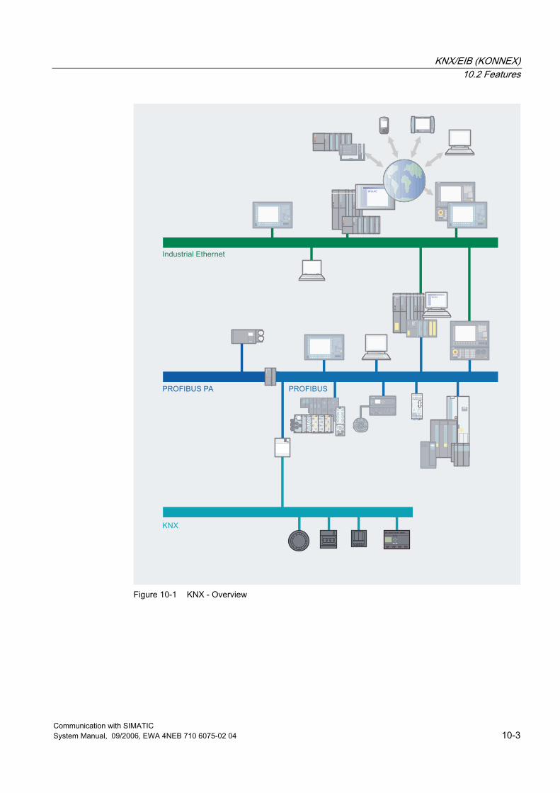
KNX/EIB (KONNEX) 10.2 Features
Communication with SIMATIC System Manual, 09/2006, EWA 4NEB 710 6075-02 04 10-3
Figure 10-1 KNX - Overview
KNX/EIB (KONNEX) 10.2 Features
Communication with SIMATIC 10-4 System Manual, 09/2006, EWA 4NEB 710 6075-02 04
The devices communicate using standardized commands. The programming and configuration of the nodes is carried out with a special Engineering Tool Software (ETS): ● ETS is a multi-vendor tool for the practical planning, commissioning and maintenance of
KNX/EIB installations. ● ETS, which is provided by the EIBA umbrella organization, assures compatible interaction
(interoperability) of components from different manufacturers. A KNX/EIB visualization enables the user to view the desired system statuses and to operate remote controls. Add-on programs such as time, interrupt, and data recording tools, etc., transform an EIB display into a full management station for the building automation system. Finally, KNX/EIB services such as remote maintenance, remote readout of consumption data, and security services are offered. The functionality of any existing EIB system can be expanded with KNX. In addition, seamless integration of additional services such as networking of electrical equipment (household appliances, etc.) is possible.
Training Certified training centers offer qualified training in locations throughout Germany.
Advantages The decisive feature of KNX/EIB is the reduction in lines, resulting in further advantages: ● Building installations can be accomplished more easily and later expanded and modified
without difficulty. ● If the usage or room configuration changes, the KNX/EIB system can be adapted by
simply reassigning (reparameterizing) the bus nodes without having to re-lay the lines. ● The bus cable can be tapped at any time and does not require a terminating resistor.
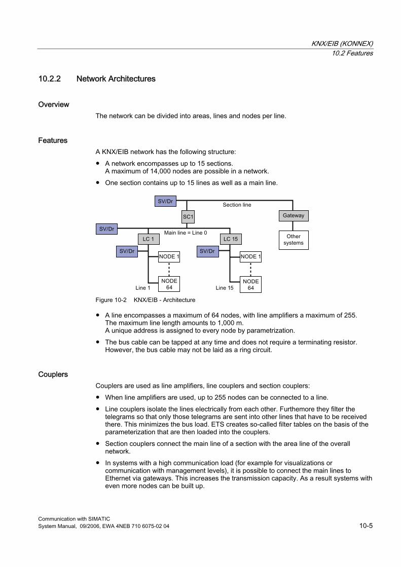
KNX/EIB (KONNEX) 10.2 Features
Communication with SIMATIC System Manual, 09/2006, EWA 4NEB 710 6075-02 04 10-5
10.2.2 Network Architectures
Overview The network can be divided into areas, lines and nodes per line.
Features A KNX/EIB network has the following structure: ● A network encompasses up to 15 sections.
A maximum of 14,000 nodes are possible in a network. ● One section contains up to 15 lines as well as a main line.
Figure 10-2 KNX/EIB - Architecture
● A line encompasses a maximum of 64 nodes, with line amplifiers a maximum of 255. The maximum line length amounts to 1,000 m. A unique address is assigned to every node by parametrization.
● The bus cable can be tapped at any time and does not require a terminating resistor. However, the bus cable may not be laid as a ring circuit.
Couplers Couplers are used as line amplifiers, line couplers and section couplers: ● When line amplifiers are used, up to 255 nodes can be connected to a line. ● Line couplers isolate the lines electrically from each other. Furthemore they filter the
telegrams so that only those telegrams are sent into other lines that have to be received there. This minimizes the bus load. ETS creates so-called filter tables on the basis of the parameterization that are then loaded into the couplers.
● Section couplers connect the main line of a section with the area line of the overall network.
● In systems with a high communication load (for example for visualizations or communication with management levels), it is possible to connect the main lines to Ethernet via gateways. This increases the transmission capacity. As a result systems with even more nodes can be built up.

KNX/EIB (KONNEX) 10.3 Technologies
Communication with SIMATIC 10-6 System Manual, 09/2006, EWA 4NEB 710 6075-02 04
10.2.3 Network Components The network components of KNX/EIB are the bus line and the couplers.
10.2.4 Connection Systems The KNX/EIB components are connected to the bus line by means of EIB terminals.
10.3 Technologies
10.3.1 Transmission Methods
Overview At KNX/EIB the data are transferred serially to various media.
Features The data transfer is carried out serially with 9.6 kbps in the form of voltage differences. The nodes send an acknowledgement when they have received a telegram. KNX/EIB supports the following transmission media: ● Twisted pair (copper) ● Powernet PL ● Radio ● Infrared ● Fiber-optic conductor (fiber-glass) ● Internet ● ISDN Radio and infrared provide good possibilities for retrofitting buildings. In the case of a two-wire cable (twisted pair copper cable) the data as well as the voltage supply (24 VDC) are routed in a short-circuit-proof manner.
KNX/EIB (KONNEX) 10.3 Technologies
Communication with SIMATIC System Manual, 09/2006, EWA 4NEB 710 6075-02 04 10-7
10.3.2 Access Methods
Overview Data exchange is carried out by means of telegrams analogously to Ethernet, meaning that the individual bus nodes can transmit independently of each other. If a collision occurs, the respective telegram is transmitted again and the transmitting node receives a confirmation of receipt.
Features A wired Ethernet network operates according to the CSMA/CD access method (Carrier Sense Multiple Access with Collision Detection). Once the ready-to-send node has listened in on the cable and identifies it to be free (Carrier Sense, CS), the data are transmitted. During transmission, the transmitting node can detect a collision (Collision Detection, CD) between itself and other simultaneously transmitting nodes (Multiple Access, MA) based on a faulted signal level. In this case the transmitter terminates the transmission process. In KNX/EIB, this mechanism is applied in the same way except that collisions are deliberately avoided (Collision Avoidance, CA). For this reason, KNX/EIB does not use the CSMA/CD method, in which permitted collisions are detected. Rather, KNX/EIB uses the CSMA/CA method (Carrier Sense Multiple Access with Collision Avoidance). Before every transmission every node checks whether the medium is free.
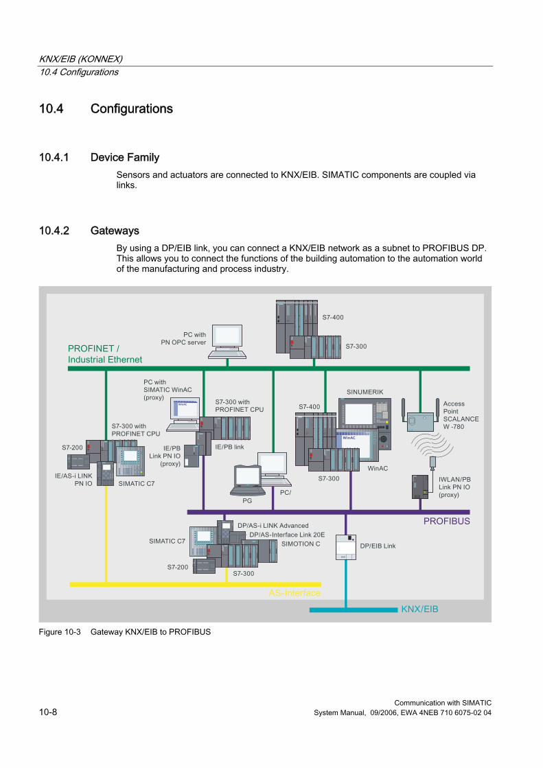
KNX/EIB (KONNEX) 10.4 Configurations
Communication with SIMATIC 10-8 System Manual, 09/2006, EWA 4NEB 710 6075-02 04
10.4 Configurations
10.4.1 Device Family Sensors and actuators are connected to KNX/EIB. SIMATIC components are coupled via links.
10.4.2 Gateways By using a DP/EIB link, you can connect a KNX/EIB network as a subnet to PROFIBUS DP. This allows you to connect the functions of the building automation to the automation world of the manufacturing and process industry.
Figure 10-3 Gateway KNX/EIB to PROFIBUS
KNX/EIB (KONNEX) 10.4 Configurations
Communication with SIMATIC System Manual, 09/2006, EWA 4NEB 710 6075-02 04 10-9
10.4.3 Connection of Other Systems KNX/EIB can also be connected by means of corresponding interfaces to other systems, for example: ● Control centers of other systems for building automation (for example SICLIMAT) ● Public telephone network (for example ISDN) In the case of higher amounts of data so-called gateways are used that implement the respective protocols of the participating networks. All major manufacturers of building automation systems currently offer this type of connection. The connection of KNX/EIB to open Standard Building Automation and Control Network (BACnet) is also becoming more revalent. However, interfaces are also required for subsystems or auxiliary systems, e.g., for simultaneous operation of EIB systems and media systems over a common computer screen. The connection between KNX/EIB and the Internet is becoming increasingly important - particularly in the home field. It allows important data, such as the room temperature to be checked and, if necessary, adjusted, while away from home.

KNX/EIB (KONNEX) 10.4 Configurations
Communication with SIMATIC 10-10 System Manual, 09/2006, EWA 4NEB 710 6075-02 04
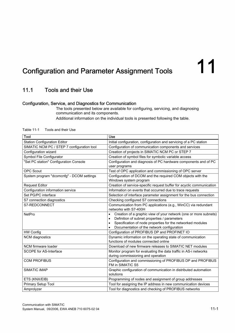
Communication with SIMATIC System Manual, 09/2006, EWA 4NEB 710 6075-02 04 11-1
Configuration and Parameter Assignment Tools 1111.1 Tools and their Use
Configuration, Service, and Diagnostics for Communication The tools presented below are available for configuring, servicing, and diagnosing communication and its components. Additional information on the individual tools is presented following the table.
Table 11-1 Tools and their Use
Tool Use Station Configuration Editor Initial configuration, configuration and servicing of a PC station SIMATIC NCM PC / STEP 7 configuration tool Configuration of communication components and services Configuration wizard Creation of projects in SIMATIC NCM PC or STEP 7 Symbol File Configurator Creation of symbol files for symbolic variable access "Set PC station" Configuration Console Configuration and diagnosis of PC hardware components and of PC
user programs OPC Scout Test of OPC application and commissioning of OPC server System program "dcomcnfg" - DCOM settings Configuration of DCOM and the required COM objects with the
Windows system program Request Editor Creation of service-specific request buffer for acyclic communication Configuration information service Information on events that occurred due to trace requests Set PG/PC interface Selection of interface parameter assignment for the bus connection S7 connection diagnostics Checking configured S7 connections S7-REDCONNECT Communication from PC applications (e.g., WinCC) via redundant
networks with S7-400H NetPro • Creation of a graphic view of your network (one or more subnets)
• Definition of subnet properties / parameters • Specification of node properties for the networked modules • Documentation of the network configuration
HW Config Configuration of PROFIBUS DP and PROFINET IO NCM diagnostics Dynamic information on the operating state of communication
functions of modules connected online NCM firmware loader Download of new firmware releases to SIMATIC NET modules SCOPE for AS-Interface Monitor program for evaluating the data traffic in AS-i networks
during commissioning and operation COM PROFIBUS Configuration and commissioning of PROFIBUS DP and PROFIBUS
FM in SIMATIC S5 SIMATIC iMAP Graphic configuration of communication in distributed automation
solutions ETS (KNX/EIB) Programming of nodes and assignment of group addresses Primary Setup Tool Tool for assigning the IP address in new communication devices Amprolyzer Tool for diagnostics and checking of PROFIBUS networks

Configuration and Parameter Assignment Tools 11.1 Tools and their Use
Communication with SIMATIC 11-2 System Manual, 09/2006, EWA 4NEB 710 6075-02 04
Station Configuration Editor The Station Configuration Editor gives you access to the component management function of the station manager in the PC station. The Station Configuration Editor is required for the initial configuration (alternative to remote configuration) as well as for configuring and servicing a PC station.
Configuration tool SIMATIC NCM PC / STEP 7 SIMATIC NCM PC is the central tool that you use to configure the communication services for your PC station. The configuration data generated with this tool must be downloaded to the PC station or exported. This makes the PC station ready for communication.
Configuration wizard The configuration wizard is used for creating projects in SIMATIC NCM PC or STEP 7. It enables automatic transfer of configuration data to the local PC station. Thus, it provides greater certainty of consistent configuration data. A typical use case, for example, is the transfer of PC station configuration data to a "temporary" STEP 7 project. The initial configuration in the Component Configurator should be completed. This project can then be transferred to an engineering station (by using the copy function to insert the PC station in a different project or by importing the project in a multiproject).
Symbol File Configurator The Symbol File Configurator can be used to create symbol files that enable symbolic variable access via the SIMATIC NET OPC Server. A symbol file is structured hierarchically and similar to a file system in this regard.
"Set PC station" Configuration Console The "Set PC station" Configuration Console is embedded as snap-in program in the Microsoft Management Console (MMC) and provides versatile options of configuring and diagnosing PC hardware components and PC user programs. Settings on the OPC servers provided with the communication software can also be made in the configuration console. Tasks supported by the "Set PC station" Configuration Console for handling the communication system of a SIMATIC PC station: ● Commissioning and operation ● Editing the configuration ● Diagnostics
Configuration and Parameter Assignment Tools 11.1 Tools and their Use
Communication with SIMATIC System Manual, 09/2006, EWA 4NEB 710 6075-02 04 11-3
OPC Scout The OPC Scout can be used to test an OPC application or commission the OPC server. To do so, you must be familiar with the terminology and mechanisms of OPC (OPC server and OPC client). You will find basic information as well as detailed information in the Industrial Communication with PG/PC manual.
System program "dcomcnfg" - DCOM settings For a client to utilize a COM object on another computer, the properties of the COM object must be configured on the client computer and on the remote computer. The Windows system program dcomcnfg is used to configure DCOM and the required COM objects.
Request Editor This tool is used to create service-specific request buffers for acyclic communication.
Configuration information service The information services provides information on events that occurred due to activated trace requests. Users can input trace requests on the "Set PC station" Configuration Console.
Set PG/PC interface You can operate your PG or PC on various bus systems used for networking automation systems (e.g., MPI bus, PROFIBUS, Industrial Ethernet). Each of your integrated and installed interfaces is represented by an interface parameter assignment. An interface parameter assignment is the parameter set of an interface. Your applications (STEP 7, WinCC, etc.) access your interfaces via one or more access points (an access point establishes the connection between an application, an interface parameter assignment, and a module). The selection of the access point of an application and its interface parameter assignment sets the access path. During parameter assignment of the PG/PC interface, you select the interface parameter assignment that is suitable for connection to the respective bus. If necessary, you can adapt the properties of the interface parameter assignment to the application-specific conditions.
Note For STEP 7, only the "S7ONLINE (STEP 7)" access point is used.
Configuration and Parameter Assignment Tools 11.1 Tools and their Use
Communication with SIMATIC 11-4 System Manual, 09/2006, EWA 4NEB 710 6075-02 04
S7 connection diagnostics You can use the "S7 connection diagnostics" program to check which S7 connections are configured on your PC. The S7 connections are read with the associated connection details from the configuration data of the Station Configuration Editor. The current connection status is also displayed. The following S7 connections types are differentiated: ● S7 connection ● S7 connection, fault-tolerant
S7-REDCONNECT S7-REDCONNECT provides for problem-free communication between PC applications (e.g., WinCC) and S7-400H over redundant connections. Industrial Ethernet and PROFIBUS networks can be configured redundantly using switches of the SCALANCE X product line, OSM, ESM, and OLM. A ring closure means that the network can continue to function if one transmission path of the network fails; if a network component fails, only the nodes connected to it are inaccessible.
NetPro Regardless of whether you want to carry out communication via global data communication or via communication blocks in the user program: The basis for communication is always a previously configured network. Configuration and parameterization of your system network is extremely simple and straightforward with NetPro. With NetPro: ● You create a graphical view of your network (one or more subnets). ● You specify the subnet properties/parameters for each subnet. ● You specify the node properties for each networked module. ● You document your network configuration.
NCM diagnostics The NCM S7 diagnostics supplies dynamic information on the operating status of communication functions for modules that are connected online.
NCM firmware loader The firmware loader enables you to reload new firmware releases to SIMATIC NET modules. It is used for: ● PROFIBUS modules ● Industrial Ethernet modules ● Modules for gateways (e.g., IE/PB link) New firmware must be loaded if, for example, the functionality of the firmware has been expanded. To find out whether a firmware update is necessary, contact your local SIEMENS representative.
Configuration and Parameter Assignment Tools 11.1 Tools and their Use
Communication with SIMATIC System Manual, 09/2006, EWA 4NEB 710 6075-02 04 11-5
SCOPE for AS-Interface The diagnostics software SCOPE for AS-i is a monitoring program which can record and analyze data traffic on AS-i networks in the commissioning phase or when the system is in operation. SCOPE for AS-Interface can be run on a PC together with the AS-i master interface module CP 2413 in Windows. SCOPE for AS-Interface offers the following functions: ● Online display of all master and slave user data at a glance (data monitor) ● Monitoring of slave activities ● Online display of basic statistics on the bus traffic ● Trigger and filter functions for recording ● Recording of all data traffic in a ring buffer ● Documentation functions
COM PROFIBUS COM PROFIBUS is available for easy configuring and commissioning of PROFIBUS DP and PROFIBUS FM in SIMATIC S5. Functions: ● Easy configuration of DP masters and DP slaves ● Easy configuration of FMS masters and FMS stations ● Setting the transmission rate for PROFIBUS ● Direct data transmission from and to the master (export/import) ● Support for commissioning with diagnostic functions ● Displaying status of inputs and outputs, setting outputs to a defined value (modifying) ● Documentation of the configuration The configuration documentation enables simple, operator-prompted creation of the address list and the parameters for slave devices. The following settings can be made: ● PROFIBUS address ● Addressing range to be used to address the I/O modules ● Start addresses of the I/O modules ● Slave-specific parameter assignment, e.g., measuring range of an analog input channel. Furthermore, the following can be performed: ● Adjustment of the transmission rate ● Adjustment of the failure characteristics ● Support for the diagnostic repeater (to start topology determination) With COM PROFIBUS, faults can be isolated during commissioning or normal operation provided there is an online connection between the PG/PC and PROFIBUS DP. When the diagnostic repeater is used in the DP network, the location and type of the fault can be displayed graphically in COM PROFIBUS.
Configuration and Parameter Assignment Tools 11.1 Tools and their Use
Communication with SIMATIC 11-6 System Manual, 09/2006, EWA 4NEB 710 6075-02 04
SIMATIC iMAP SIMATIC iMap is a component-based software tool for configuring communication in distributed automation solutions. SIMATIC iMap is used to graphically configure the data exchange between technological modules. SIMATIC iMap is based on PROFINET, i.e. the standard communications protocol of the PROFIBUS User Organisation (PUO), in order to ensure compatibility of data exchange between "intelligent field devices" of different manufacturers. SIMATIC iMap can be integrated as a higher-level configuration tool in existing concepts, e.g., Totally Integrated Automation. In this case, the library elements are created using STEP 7.
ETS (KNX/EIB) The ETS software is used to program the nodes and assign the group addresses. ETS, which is provided by the EIBA umbrella organization, assures compatible interaction of components from different manufacturers.
PST (Primary Setup Tool) Tool for assigning the IP address for communication devices. The following options are available for assigning an IP address to a non-configured device that is lacking one: ● DHCP ● STEP 7 ● NCM PC ● Via Primary Setup Tool V3.0 The only requirement for using the Primary Setup Tool is that the devices are accessible via Ethernet. The Primary Setup Tool uses the DLC protocol for the communication between the modules. Supported operating systems The Primary Setup Tool can be installed and executed under the following operating systems: ● Windows XP Professional ● Windows 2000 Professional SP2

Configuration and Parameter Assignment Tools 11.1 Tools and their Use
Communication with SIMATIC System Manual, 09/2006, EWA 4NEB 710 6075-02 04 11-7
Amprolyzer The Amprolyzer (Advanced Multicard Profibus AnaLYZER) is a diagnostic software tool for PROFIBUS. The tool is an important aid for commissioning and service engineers when testing PROFIBUS networks. For the device manufacturer Amprolyzer is an indispensable tool for developing PROFIBUS products. Functions ● Comprehensive list of all PROFIBUS nodes located on the bus ● Overview diagnostics with the current operating statuses of the nodes ● Bus statistics with the number of events, e.g., timeouts and message frame repetitions ● Automatic detection of the transmission rate ● Message frame recording with trigger and filter options with respect to events and
message frame contents, including time stamp ● Storage and export of message frame recordings in Excel format ● Support for Windows 2000 (min. SP2) / Windows XP Professional
Further Information Your Area of Interest Document Configuration tool SIMATIC NCM PC / STEP 7
"Commissioning PC Stations - Introduction and Getting Started" manual and the STEP 7 documentation and online help.
Configuration wizard "Commissioning PC Stations – Introduction and Getting Started" manual. Symbol File Configurator "Commissioning PC Stations – Introduction and Getting Started" manual. "Set PC station" Configuration Console "Commissioning PC Stations – Introduction and Getting Started" manual. OPC Scout "Commissioning PC Stations – Introduction and Getting Started" manual. System program "dcomcnfg" - DCOM settings
"Commissioning PC Stations – Introduction and Getting Started" manual.
NCM S7 Diagnostics For more information on the NCM S7 diagnostic procedures and a checklist for using the diagnostics in typical problem scenarios, refer to the manuals for NCM. • "S7-CPs for Industrial Ethernet - Configuring and Commissioning" manual • "S7-CPs for PROFIBUS - Configuring and Commissioning" manual • "NCM-S7 for PROFIBUS/FMS" manual
SCOPE for AS-Interface Windows conventions are used to operate this software. The detailed function scope is available in the SIMATIC NET catalog and the product manual.
Installing the Primary Setup Tool The Primary Setup Tool is available from Siemens Automation and Drives Service & Support on the Internet under the article ID 19440762. You can access this entry at the following URL: http://support.automation.siemens.com/WW/view/en/19440762
Amprolyzer Amprolyzer is available from Siemens Automation and Drives Service & Support on the Internet under Entry ID 18609432. You can access this entry at the following URL: http://support.automation.siemens.com/WW/view/en/18609432
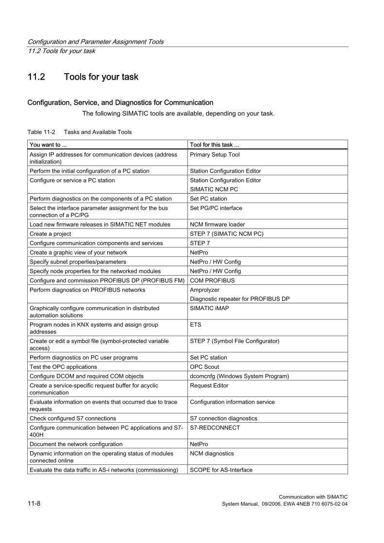
Configuration and Parameter Assignment Tools 11.2 Tools for your task
Communication with SIMATIC 11-8 System Manual, 09/2006, EWA 4NEB 710 6075-02 04
11.2 Tools for your task
Configuration, Service, and Diagnostics for Communication The following SIMATIC tools are available, depending on your task.
Table 11-2 Tasks and Available Tools
You want to ... Tool for this task ... Assign IP addresses for communication devices (address initialization)
Primary Setup Tool
Perform the initial configuration of a PC station Station Configuration Editor Configure or service a PC station Station Configuration Editor
SIMATIC NCM PC Perform diagnostics on the components of a PC station Set PC station Select the interface parameter assignment for the bus connection of a PC/PG
Set PG/PC interface
Load new firmware releases in SIMATIC NET modules NCM firmware loader Create a project STEP 7 (SIMATIC NCM PC) Configure communication components and services STEP 7 Create a graphic view of your network NetPro Specify subnet properties/parameters NetPro / HW Config Specify node properties for the networked modules NetPro / HW Config Configure and commission PROFIBUS DP (PROFIBUS FM) COM PROFIBUS Perform diagnostics on PROFIBUS networks Amprolyzer
Diagnostic repeater for PROFIBUS DP Graphically configure communication in distributed automation solutions
SIMATIC iMAP
Program nodes in KNX systems and assign group addresses
ETS
Create or edit a symbol file (symbol-protected variable access)
STEP 7 (Symbol File Configurator)
Perform diagnostics on PC user programs Set PC station Test the OPC applications OPC Scout Configure DCOM and required COM objects dcomcnfg (Windows System Program) Create a service-specific request buffer for acyclic communication
Request Editor
Evaluate information on events that occurred due to trace requests
Configuration information service
Check configured S7 connections S7 connection diagnostics Configure communication between PC applications and S7-400H
S7-REDCONNECT
Document the network configuration NetPro Dynamic information on the operating status of modules connected online
NCM diagnostics
Evaluate the data traffic in AS-i networks (commissioning) SCOPE for AS-Interface
Communication with SIMATIC System Manual, 09/2006, EWA 4NEB 710 6075-02 04 Glossary-1
Glossary
10 Base-T/F Ethernet standard that allows transmission of 10 Mbps.
100 Base-T/F Ethernet standard that allows transmission of up to 100 Mbps.
1000 Base-T/F Ethernet standard that allows transmission of up to 1000 Mbps.
Accumulator Accumulators represent CPU register and are used as buffer memory for download, transfer, comparison, calculation and conversion operations.
Address An address is the identifier of a specific address or address area. Examples: Input I 12.1; Flag Word MW 25; Data Block DB 3.
Analog module Analog modules convert process values (e.g. temperature) into digital values which can be processing in the CPU, or they convert digital values into analog manipulated variables.
API API (Application Process Identifier) is a parameter the value of which specifies the IO data processing process (application). The PROFINET standard IEC 61158 assigns profiles to specific APIs (PROFIdrive, PROFIslave), and these are defined in the context of the PROFINET Nutzerorganisation. The standard API is 0.
Glossary
Communication with SIMATIC Glossary-2 System Manual, 09/2006, EWA 4NEB 710 6075-02 04
Application An application is a program that runs directly on the MS-DOS / Windows operating system. Applications on the PG include, for example, the STEP 5 basic package, GRAPH 5 and others. → User program
Backplane bus The backplane bus is a serial data bus. It supplies power to the modules and is also used by the modules to communicate with each other. Bus connectors interconnect the modules.
Backup memory Backup memory ensures buffering of the memory areas of a CPU without backup battery. It backs up a configurable number of timers, counters, flag bits, data bytes and retentive timers, counters, flag bits and data bytes).
BERO A position switch that works without any touch or contact being involved. A distinction is drawn between inductive and capacitive BEROs.
Bus A bus is a communication medium connecting several nodes. Data can be transferred via serial or parallel circuits, that is, via electrical conductors or fiber optic.
Bus segment A bus segment is a self-contained section of a serial bus system. Bus segments are interconnected via repeaters.
CAT 3 Twisted-pair cable does not always the same thing. Several versions are specified in the Ethernet standard. There are several categories, however only CAT 3 and CAT 5 are relevant for networks. The two types of cable differ in the maximum permitted frequency and the values for attenuation (weakening of the signal over a certain distance). CAT 3 is a twisted-pair cable for Ethernet with 10 Base-T. CAT 5 is a twisted-pair cable for Fast Ethernet with 100 Base-T.
CAT 5 → CAT 3
Glossary
Communication with SIMATIC System Manual, 09/2006, EWA 4NEB 710 6075-02 04 Glossary-3
Category 3 → CAT 3
Category 5 → CAT 3
Changeover contact Auxiliary switch with only one contact piece that has a closed position for when the switching device is closed and another closed position for when it is open.
Clock flag bits Flag bit which can be used to generate clock pulses in the user program (1 byte per flag bit).
Note When operating with S7300 CPUs, make sure that the byte of the clock memory bit is not overwritten in the user program!
Coaxial Cable A coaxial cable, also known as "coax", is a metallic cabling system used in high-frequency transmission, for example, as the antenna cable for radios and televisions as well as in modern networks in which high data transmission rates are required. In a coaxial cable, an inner conductor is surrounded by an outer tube-like conductor. The two conductors are separated by a dielectric layer. In contrast to other cables, this design provides a high degree of immunity to and low emission of electromagnetic interference.
Code block A SIMATIC S7 code block contains part of the STEP 7 user program. (in contrast to a DB: this contains only data.)
COM Component Object Model - specification of the Microsoft Corporation for Windows objects, on an OLE basis. Automation systems are mapped on objects in PROFINET CBA. An object consists of interfaces and properties. Using these interfaces and properties, two objects can communicate. → DCOM
Glossary
Communication with SIMATIC Glossary-4 System Manual, 09/2006, EWA 4NEB 710 6075-02 04
Communication processor Communications processors are modules for point-to-point and bus links.
Compress The PG online function "Compress" is used to rearrange all valid blocks in CPU RAM in one continuous area of user memory, starting at the lowest address. This eliminates fragmentation which occurs when blocks are deleted or edited.
Configuration Assignment of modules to module racks/slots and (e.g. for signal modules) addresses.
Consistent data Data which are related in their contents and not to be separated are referred to as consistent data. For example, the values of analog modules must always be handled as a whole, that is, the value of an analog module must not be corrupted as a result of read access at two different points of time.
Counters Counters are part of CPU system memory. The content of "Counter cells" can be modified by STEP 7 instructions (for example, up/down count.)
CP → Communication processor
CPU Central processing unit = CPU of the S7 automation system with a control and arithmetic unit, memory, operating system, and interface for programming device. → CPU
CRC Cyclic Redundancy Check Cyclic Redundancy Check. A checksum used in transmission protocols to detect errors in frames.
Glossary
Communication with SIMATIC System Manual, 09/2006, EWA 4NEB 710 6075-02 04 Glossary-5
Cut Through In the Cut Through process not the entire data package is stored temporarily in a buffer, but is passed directly onto the target port as soon as the first 6 bytes (target address) have been read. The times required by the data package to pass the switch are then minimal. The data are only stored temporarily in accordance with the Store and Forward process when the section between the target part and the port of the next switch is occupied.
Cycle time The cycle time represents the time a CPU requires for one execution of the user program.
Cyclic interrupt → Interrupt, cyclic interrupt
Data block Data blocks (DB) are data areas in the user program which contain user data. There are global data blocks which can be accessed by all code blocks, and instance data blocks which are assigned to a specific FB call.
Data, static Static data can only be used within a function block. These data are saved in an instance data block that belongs to a function block. Data stored in an instance data block are retained until the next function block call.
Data, temporary Temporary data represent local data of a block. They are stored in the L-stack when the block is executed. After the block has been processed, these data are no longer available.
DCOM Distributed COM - expansion of the COM standard for the remote object communication beyond device restrictions. DCOM sets a protocol on the RPC, which in turn uses TCP/IP as a basis. Exchange PROFINET CBA devices with the help of DCOM data that is not time-sensitive - e.g. process data, diagnostic data, configurations etc.. DCOM technology is supported by PROFINET Version V1.0 and higher. The PNO provides its users with a portable DCOM protocol stack customized for PROFINET. This eliminates dependency on Microsoft and its further developments in this technology while at the same time ensuring compatibility with Microsoft products. → COM
Glossary
Communication with SIMATIC Glossary-6 System Manual, 09/2006, EWA 4NEB 710 6075-02 04
Diagnostic buffer The diagnostics buffer represents a buffered memory area in the CPU. It stores diagnostic events in the order of their occurrence.
Diagnostic interrupt Modules capable of diagnostics operations report detected system errors to the CPU by means of diagnostic interrupts.
Diagnostics → System diagnostics
DP master A master which behaves in accordance with EN 50170, Part 3 is known as a DP master.
DP slave A slave operated on PROFIBUS with PROFIBUS DP protocol and in accordance with EN 50170, Part 3 is referred to as DP slave.
DPV1 The designation DPV1 means extension of the functionality of the acyclical services (to include new interrupts, for example) provided by the DP protocol. The DPV1 functionality has been incorporated into IEC 61158/EN 50170, volume 2, PROFIBUS.
Electrically isolated The reference potential of the control and on-load power circuits of isolated I/O modules is electrically isolated; for example, by optocouplers, relay contact or transformer. I/O circuits can be interconnected with a root circuit.
Encoder Encoders (sensors) are used for the precise detection of digital signals and paths, positions, speeds, revolutions, weights, etc.
Equipotential bonding Electrical connection (equipotential bonding conductor) which eliminates potential difference between electrical equipment and external conductive bodies by drawing potential to the same or near the same level, in order to prevent disturbing or dangerous voltages between these bodies.
Glossary
Communication with SIMATIC System Manual, 09/2006, EWA 4NEB 710 6075-02 04 Glossary-7
Error display One of the possible reactions of the operating system to a runtime error is to output an error message. Further reactions: Error reaction in the user program, CPU in STOP.
Error handling via OB After the operating system has detected a specific error (e.g. access error with STEP 7), it calls a dedicated block (Error OB) that determines further CPU actions.
Error response Reaction to a runtime error. Reactions of the operating system: It sets the automation system to STOP, indicates the error, or calls an OB in which the user can program a reaction.
ERTEC ERTEC - Enhanced Real Time Ethernet Controller" The new ASICs ERTEC200 and ERTEC400 intended for automation applications support the PROFINET protocol and are required for the IRT operation. As PROFINET is an open standard, "the" Siemens AG offers these PROFINET ASICs for the development of its own devices. ASIC is the acronym for Application Specific Integrated Circuits. PROFINET ASICs are components with a wide range of functions for the development of your own devices. They implement the requirements of the PROFINET standard in a circuit and allow extremely high packing densities and performance. For you, the benefits of ERTEC are as follows: ● Simple integration of switch functionality in devices ● Simple and cost-effective setup of bus structures ● Minimization of the communication load of devices
Fast Ethernet → 100 Base-T/F
FB → Function block
FC → Function
Flag bits Flag bits are part of the CPU's system memory. They store intermediate results of calculations. They can be accessed in bit, word or dword operations.
Glossary
Communication with SIMATIC Glossary-8 System Manual, 09/2006, EWA 4NEB 710 6075-02 04
Flash EPROM FEPROMs can retain data in the event of power loss, same as electrically erasable EEPROMs. However, they can be erased within a considerably shorter time (FEPROM = Flash Erasable Programmable Read Only Memory). They are used on Memory Cards.
Force The Force function can be used to assign the variables of a user program or CPU (also: inputs and outputs) constant values. In this context, please note the limitations listed in the Overview of the test functions section in the chapter entitled Test functions, Diagnostics and Troubleshooting in the S7-300 Installation manual.
Function According to IEC 1131-3, a function (FC) is a code block without static data. A function allows transfer of parameters in user program. Functions are therefore suitable for programming frequently occurring complex functions, e.g. calculations.
Function block According to IEC 1131-3, a function block (FB) is a code block with static data. An FB allows the user program to pass parameters. Function blocks are therefore suitable for programming frequently occurring complex functions, e.g. controls, mode selections.
Functional ground Grounding which has the sole purpose of safeguarding the intended function of electrical equipment. With functional grounding you short-circuit interference voltage which would otherwise have an unacceptable impact on equipment.
GD circuit A GD circuit comprises a number of CPUs sharing data by means of global data communication, and is used as follows: ● A CPU broadcasts a GD packet to the other CPUs. ● A CPU sends and receives a GD packet from another CPU. A GD circuit is identified by a GD circuit number.
GD element A GD element is generated by assigning shared global data. It is identified by a unique global data ID in the global data table.
GD packet A GD packet can consist of one or several GD elements transmitted in a single message frame.
Glossary
Communication with SIMATIC System Manual, 09/2006, EWA 4NEB 710 6075-02 04 Glossary-9
Global data Global data can be addressed from any code block (FC, FB, OB). In particular, this refers to flag bits M, inputs I, outputs Q, timers, counters and data blocks DB. Global data can be accessed via absolute or symbolic addressing.
Global data communication Global data communication is a method of transferring global data between CPUs (without CFBs).
Ground The conductive earth whose electrical potential can be set equal to zero at any point. Ground potential can be different from zero in the area of grounding electrodes. The term reference ground is frequently used to describe this situation. Grounding means, to connect an electrically conductive component via an equipotential grounding system to a grounding electrode (one or more conductive components with highly conductive contact to earth). Chassis ground is the totality of all the interconnected passive parts of a piece of equipment on which dangerous fault-voltage cannot occur.
GSD file The properties of a PROFINET device are described in a GSD file (General Station Description) that contains all the information required for configuration. Similar to PROFIBUS, you can implement a PROFINET device in STEP 7 by installing a GSD file. In PROFINET IO, the GSD file is in XML format. The structure of the GSD file is compliant with ISO 15734, which is the world-wide standard for device descriptions. In PROFIBUS, the GSD file is in ASCII format.
HART English: Highway Adressable Remote Transducer
IEEE Institute of Electrical and Electronics Engineers
IEEE 802 Institute of Electrical and Electronics Engineers LAN/MAN Standards Committee
Glossary
Communication with SIMATIC Glossary-10 System Manual, 09/2006, EWA 4NEB 710 6075-02 04
IEEE 802.3 Institute of Electrical and Electronics Engineers Fast Ethernet working committee
Industrial Ethernet Area and cell network in accordance with the standard IEEE 802.3 (Ethernet), IEEE 802.3u and IEEE 802.11 a/b/g/h (Wireless LAN). Industrial Ethernet is an extension of the Ethernet standard. Industrial Ethernet combines rules and standards that have the aim of allowing Ethernet to be used in industrial production. Industrial Ethernet creates the possibility of connecting the conventional office network with the devices for controlling monitoring production processes. Devices in Industrial Ethernet fulfill particular requirements with regard to usage in an industrial environment.
Requirement Property Protection against dust and splash water Increased degree of protection IP 65/67 Mounting DIN rail 35 mm Resistance to vibration Extended operating temperature range Transfer of the data in real-time Isochronous real-time Failure safety Ring topology with redundant line
Industrial Ethernet → 100 Base-T/F
Instance data block The STEP 7 user program assigns an automatically generated DB to every call of a function block. The instance data block stores the values of inputs / outputs and in/out parameters, as well as local block data.
Interface, MPI-capable → MPI
Interrupt The CPU's operating system knows 10 different priority classes for controlling user program execution. These priority classes include interrupts, e.g. process interrupts. When an interrupt is triggered, the operating system automatically calls an assigned OB. In this OB the user can program the desired response (e.g. in an FB).
Glossary
Communication with SIMATIC System Manual, 09/2006, EWA 4NEB 710 6075-02 04 Glossary-11
Interrupt, cyclic interrupt A cyclic interrupt is generated periodically by the CPU in a configurable time pattern. A corresponding OB will be processed.
Interrupt, delay The delay interrupt belongs to one of the priority classes in SIMATIC S7 program processing. It is generated on expiration of a time started in the user program. A corresponding OB will be processed.
Interrupt, delay → Interrupt, delay
Interrupt, diagnostic → Diagnostic interrupt
Interrupt, process → Process interrupt
Interrupt, status A status interrupt can be generated by a DPV1 slave and causes OB 55 to be called on the DPV1 master. For detailed information on OB 55, see the Reference Manual System software for S7-300/400: System and Standard Functions.
Interrupt, time-of-day The time-of-day interrupt belongs to one of the priority classes in SIMATIC S7 program processing. It is generated at a specific date (or daily) and time-of-day (e.g. 9:50 or hourly, or every minute). A corresponding OB will be processed.
Interrupt, update An update interrupt can be generated by a DPV1 slave and causes OB56 to be called on the DPV1 master. For detailed information on OB56, see the Reference Manual System software for S7-300/400: System and Standard Functions.
Interrupt, vendor-specific A vendor-specific interrupt can be generated by a DPV1 slave. It causes OB57 to be called on the DPV1 master. For detailed information on OB 57, see the Reference Manual System Software for S7-300/400: System and Standard Functions.
Glossary
Communication with SIMATIC Glossary-12 System Manual, 09/2006, EWA 4NEB 710 6075-02 04
IO controller → PROFINET IO Controller → PROFINET IO Device → PROFINET IO Supervisor → PROFINET IO System
IO device → PROFINET IO Controller → PROFINET IO Device → PROFINET IO Supervisor → PROFINET IO System
IO supervisor → PROFINET IO Controller → PROFINET IO Device → PROFINET IO Supervisor → PROFINET IO System
IO system → PROFINET IO System
IP Internet Protocol Collection of program routines which the TCP protocol accesses
ISO International Organization for Standardization
Isochronous Real-Time Communication, IRT At PROFINET with IRT the communication cycle is subdivided into different, time-specific channels for this purpose. The first channel is used for isochronous real-time communication (IRT), followed by real-time communication (RT) and standard TCP/IP communication. In this way, both types of data data transfer exist together without interfering with each other. When this transmission method is implemented in ERTEC-ASICs (Enhanced Real-Time Ethernet Controller), cycle times of 0.25 ms and jitter accuracy below 1 µs are achieved.
Glossary
Communication with SIMATIC System Manual, 09/2006, EWA 4NEB 710 6075-02 04 Glossary-13
KNX/EIB KNX/EIB is a multi-master network for standardized network communication in the home and building system technology. KNX/EIB is maintained by the KONNEX Association and is based, inter alia, on the standard EN 50090.
LAN Local area network to which several computers are connected within an enterprise. The LAN therefore has a limited geographical span and is solely available to a company or institution.
Load memory Load memory is part of the CPU. It contains objects generated by the programming device. It is implemented either as a plug-in Memory Card or permanently integrated memory.
Load power supply Power supply to the signal / function modules and the process I/O connected to them.
Local data → Data, temporary
Maintenance demand Continuously reliable function of a PROFINET device can be achieved by means of the early detection and remedy of potential faults - before they cause a production breakdown. In addition to this, different maintenance information belonging to the maintenance demand is defined. A system alarm "maintenance demand" can be defined for various wearing parameters and, for example, when reaching a specific number of operating hours it is recommended that you inspect some of the components. The maintenance demand alarm is sent if, within a foreseeable period of time, it is necessary to replace the component in question. Example - printer: The maintenance demand alarm is then sent if the toner / printer cartridge needs to be replaced within a period of several days.
Glossary
Communication with SIMATIC Glossary-14 System Manual, 09/2006, EWA 4NEB 710 6075-02 04
Maintenance required Continuously reliable function of a PROFINET device can be achieved by means of the early detection and remedy of potential faults - before they cause a production breakdown. In addition to this, different maintenance information belonging to the maintenance required is defined. A system alarm "maintenance required" can be defined for various wearing parameters and, for example, when reaching a specific number of operating hours it is recommended that you inspect some of the components. The maintenance required alarm is sent if, with a short period of time, it is necessary to replace the component in question. Example - printer: The maintenance required alarm is then sent if the toner / printer cartridge needs to be replaced immediately.
Master When a master is in possession of the token, it can send data to other nodes and request data from other nodes (= active node). → Slave
MBP Manchester Coding and Bus Powering
Memory Card (MC) Memory Cards are memory media for CPUs and CPs. They are implemented in the form of RAM or FEPROM. An MC differs from a Micro Memory Card only in its dimensions (MC is approximately the size of a credit card).
Micro Memory Card (MMC) Micro Memory Cards are memory media for CPUs and CPs. Their only difference to the Memory Card is the smaller size.
Module parameters Module parameters are values which can be used to configure module behavior. A distinction is made between static and dynamic module parameters.
MPI The multipoint interface (MPI) is the programming device interface of SIMATIC S7. It enables multiple-node operation (PGs, text-based displays, OPs) on one or several PLCs. Each node is identified by a unique address (MPI address).
Glossary
Communication with SIMATIC System Manual, 09/2006, EWA 4NEB 710 6075-02 04 Glossary-15
MPI address → MPI
NAMUR Normenausschuss für Mess- und Regelungstechnik (German standardization committee for measurement and control engineering)
Nesting depth A block can be called from another by means of a block call. Nesting depth is referred to as the number of simultaneously called code blocks.
Network A network consists of one or more interconnected subnets with any number of nodes. Several networks can exist alongside each other.
Non-isolated The reference potential of the control and on-load power circuits of non-isolated I/O modules is electrically interconnected.
OB → Organization blocks
OB priority The CPU operating system distinguishes between different priority classes, for example, cyclic program execution, process interrupt controlled program processing. Each priority class is assigned organization blocks (OBs) in which the S7 user can program a response. The OBs are assigned different default priority classes. These determine the order in which OBs are executed or interrupt each other when they appear simultaneously.
OLE Object Linking and Embedding - Central architectural principle of Windows. OLE is a Microsoft technology that enables linking of objects and data exchange between programs.
Glossary
Communication with SIMATIC Glossary-16 System Manual, 09/2006, EWA 4NEB 710 6075-02 04
OPC OLE for Process Control - Industrial standard that allows vendor-independent access to industrial communication networks, defined on the basis of OLE. OPC (OLE for Process Control) refers to a standard interface for communication in automation engineering. With OPC, you can access OLE (Object Linking and Embedding). OLE is the component model of Microsoft. Components are the software objects or applications that make their functionality available to other applications. Communication via the OPC interface is based on COM/DCOM. In this case, the object is the process image. The OPC interface was designed as an industry standard by leading automation companies with the support of the Microsoft Corporation. Previously, applications that access process data were restricted to the access mechanisms of the communications network of one manufacturer. Now, the standardized OPC interface provides a uniform method of accessing the communication networks of any vendor.
OPC → OPC client → OPC server
OPC client An OPC client is a user program that accesses process data via the OPC interface. Access to the process data is made possible by the OPC server. → OPC → OPC server
OPC server The OPC server provides the OPC client with a wide range of functions with which it can communicate via industrial networks. You will find more detailed information in the Industrial Communication with PG/PC manual. → OPC → OPC client
Operating state SIMATIC S7 automation systems know the following operating states: STOP, START, RUN.
Operating system The CPU OS organizes all functions and processes of the CPU which are not associated to a specific control task. → CPU
Glossary
Communication with SIMATIC System Manual, 09/2006, EWA 4NEB 710 6075-02 04 Glossary-17
Organization blocks Organization blocks (OBs) form the interface between CPU operating system and the user program. The sequence for user program execution is determined in the organization blocks.
Parameters 1. Variable of a STEP 7 code block 2. Variable for declaring module response (one or several per module). All modules have a suitable basic factory setting which can be customized in STEP 7. There are static and dynamic parameters.
Parameters, dynamic Unlike static parameters, you can change dynamic module parameters during runtime by calling an SFC in the user program, e.g. limit values of an analog signal input module.
Parameters, static Unlike dynamic parameters, static parameters of modules cannot be changed by the user program. You can only modify these parameters by editing your configuration in STEP 7, for example, modification of the input delay parameters of a digital signal input module.
PCD The PROFINET component description is the description of the components you have generated in your engineering system (for example, STEP 7). The PCD is an XML file that you can import into SIMATIC iMap so that you can configure the PROFINET CBA communication.
Peer-to-peer communication In peer-to-peer communication the communication partners have equal rights and can both offer and use services.
PG → Programming device
PLC Programmable controllers (PLCs) are electronic controllers whose function is saved as a program in the control unit. Therefore, the configuration and wiring of the unit does not dependend on the PLC function. A programmable logic controller has the structure of a computer; it consists of a CPU with memory, input/output modules and an internal bus system. The I/O and the programming language are oriented to control engineering needs. A PLC in the context of SIMATIC S7 --> is a programmable logic controller. → CPU → PLC
Glossary
Communication with SIMATIC Glossary-18 System Manual, 09/2006, EWA 4NEB 710 6075-02 04
PNO → PROFIBUS International
Priority class The S7 CPU operating system provides up to 26 priority classes (or "Program execution levels"). Specific OBs are assigned to these classes. The priority classes determine which OBs interrupt other OBs. Multiple OBs of the same priority class do not interrupt each other. In this case, they are executed sequentially.
Process image The process image is part of CPU system memory. At the start of cyclic program execution, the signal states at the input modules are written to the process image of the inputs. At the end of cyclic program execution, the signal status of the process image of the outputs is transferred to the output modules.
Process interrupt A process interrupt is triggered by interrupt-triggering modules as a result of a specific event in the process. The process interrupt is reported to the CPU. The assigned organization block will be processed according to interrupt priority.
Product version The product version identifies differences between products which have the same order number. The product version is incremented when forward-compatible functions are enhanced, after production-related modifications (use of new parts/components) and for bug fixes.
PROFIBUS Process Field Bus - European fieldbus standard. → PROFIBUS DP → PROFIBUS International
PROFIBUS DP A PROFIBUS with the DP protocol that complies with EN 50170. DP stands for distributed peripheral I/O (fast, real-time, cyclic data exchange). From the perspective of the user program, the distributed I/O is addressed in exactly the same way as the central I/O. → PROFIBUS → PROFIBUS International
Glossary
Communication with SIMATIC System Manual, 09/2006, EWA 4NEB 710 6075-02 04 Glossary-19
PROFIBUS International Technical committee that defines and further develops the PROFIBUS and PROFINET standard. Also known as the PROFIBUS User Organization (PNO). Home page http://www.profibus.com
PROFINET → PROFIBUS International
PROFINET ASIC Refer to ERTEC
PROFINET Component Description → PCD
PROFINET IO Controller Device via which the connected IO devices are addressed. This means that the IO controller exchanges input and output signals with assigned field devices. The IO controller is often the controller on which the automation program runs. → PROFINET IO Device → PROFINET IO Supervisor → PROFINET IO System
PROFINET IO Device Distributed field device assigned to one of the IO controllers (for example, remote I/O, valve terminal, frequency converter, switches) → PROFINET IO Controller → PROFINET IO Supervisor → PROFINET IO System
PROFINET IO Supervisor PG/PC or HMI device for commissioning and diagnostics. → PROFINET IO Controller → PROFINET IO Device → PROFINET IO System
Glossary
Communication with SIMATIC Glossary-20 System Manual, 09/2006, EWA 4NEB 710 6075-02 04
PROFINET IO System PROFINET IO controller with assigned PROFINET IO devices. → PROFINET IO Device → PROFINET IO Controller
Programming device Basically speaking, PGs are compact and portable PCs which are suitable for industrial applications. They are identified by a special hardware and software for programmable logic controllers.
RAM Work memory is a RAM memory in the CPU which is accessed by the processor during user program execution. RAM (Random Access Memory) is a semiconductor read/write memory.
RAM Work memory is a RAM memory in the CPU which is accessed by the processor during user program execution. RAM (Random Access Memory) is a semiconductor read/write memory.
Real-Time Communication Industrial communication in which supervisors take part in communication involves runtimes during communication that are too long for production automation. When communicating time-critical IO user data, PROFINET therefore uses its own real-time channel, rather than TCP/IP.
Reduction factor The reduction rate determines the send/receive frequency for GD packets on the basis of the CPU cycle.
Reference ground → Ground
Reference potential Voltages of participating circuits are referenced to this potential when they are viewed and/or measured.
Glossary
Communication with SIMATIC System Manual, 09/2006, EWA 4NEB 710 6075-02 04 Glossary-21
Repeater Repeaters have the task of interconnecting several network segments in local networks. In the process the received electrical or optical signals are conditioned and sent to the next network node. In the conditioning process the noise and distortions (caused by the execution time) are separated from the signal and the pulse shape is restored to distortion-free.
Restart On CPU start-up (e.g. after is switched from STOP to RUN mode via selector switch or with POWER ON), OB100 (restart) is initially executed, prior to cyclic program execution (OB1). On restart, the input process image is read in and the STEP 7 user program is executed, starting at the first instruction in OB1.
Retentive memory A memory area is considered retentive if its contents are retained even after a power loss and transitions from STOP to RUN. The non-retentive area of memory flag bits, timers and counters is reset following a power failure and a transition from the STOP mode to the RUN mode. Retentive can be the: ● Flag bits ● S7 timers ● S7 counters ● Data areas
Router A router connects two subnetworks with each other. A router works in a way similar to a switch. With a router, however, it is also possible to specify which communications nodes can communicate via the router and which cannot. Communication nodes on different sides of a router can only communicate with each other if you have explicitly enabled communication between the two nodes via the router. Real time data cannot be replaced beyond subnetwork limits.
Runtime error Errors occurred in the PLC (that is, not in the process itself) during user program execution.
Segment → bus segment
SELV/PELV Term indicating circuits with safety extra-low voltage. SITOP power supplies from Siemens, for example, provide this protection. For more detailed information, refer to the EN 60950-1 (2001) standard.
Glossary
Communication with SIMATIC Glossary-22 System Manual, 09/2006, EWA 4NEB 710 6075-02 04
SFB → System function block
SFC → System function
Signal module Signal modules (SM) form the interface between the process and the PLC. There are digital input and output modules (input/output module, digital) and analog input and output modules (input/output module, analog).
SIMATIC The term denotes Siemens products and systems for industrial automation.
SIMATIC iMap Engineering tool for configuration, commissioning, and monitoring of modular distributed automation systems. It is based on the PROFINET standard.
SIMATIC NET Siemens business area for industrial communication, networks, and network components.
Slave A slave can only exchange data after being requested to by the master. → Master
STARTUP A START-UP routine is executed at the transition from STOP to RUN mode. Can be triggered by means of the mode selector switch, or after power on, or by an operator action on the programming device. An S7-300 performs a restart.
STEP 7 Engineering system. Contains programming software for the creation of user programs for SIMATIC S7 controllers.
Store and Forward In the Store and Forward process the switch stores the telegrams and rows them into a queue. The telegrams are then forwarded selectively to the specific port that can access the addressed node (Store and Forward).
Glossary
Communication with SIMATIC System Manual, 09/2006, EWA 4NEB 710 6075-02 04 Glossary-23
Substitute value Substitute values are configurable values which output modules transfer to the process when the CPU switches to STOP mode. In the event of an I/O access error, a substitute value can be written to the accumulator instead of the input value which could not be read (SFC 44).
System diagnostics System diagnostics refers to the detection, evaluation, and signaling of errors that occur within the PLC, for example programming errors or module failures. System errors can be indicated by LEDs or in STEP 7.
System function A system function (SFC) is a function integrated in the operating system of the CPU that can be called when necessary in the STEP 7 user program.
System function block System function blocks (SFB) are integrated in the CPU operating system and can be called in the STEP 7 user program.
System memory System memory is an integrated RAM memory in the CPU. System memory contains the address areas (e.g. timers, counters, flag bits) and data areas that are required internally by the operating system (for example, communication buffers).
System status list The system status list contains data that describe the current status of an S7-300 or S7-400. You can always use this list to obtain an overview of: ● The configuration of the S7-300 ● the current CPU configuration and configurable signal modules ● the current status and processes in the CPU and in configurable signal modules.
Glossary
Communication with SIMATIC Glossary-24 System Manual, 09/2006, EWA 4NEB 710 6075-02 04
TCP/IP Ethernet in actual fact is only a data transport system, comparable with a highway as system for transporting goods and passengers. The actual data transport is handled by so-called protocols, comparable with cars and commercial vehicles transporting passengers and goods on the highway. Tasks handled by the basic protocols Transmission Control Protocol (TCP) and Internet Protocol (IP) (TCP/IP in short form): 1. On the sender, the data is encapsulated in packets. 2. The packets are transported via Ethernet to the correct recipient. 3. At the receiver, the data packets are reassembled in the correct order. 4. Bad packets are sent repeatedly until they are received correctly. Most higher-level protocols use TCP/IP to handle the tasks. This is how, for example, the Hyper Text Transfer Protocol (HTTP) transfers documents on the World Wide Web (WWW) that are written in Hyper Text Markup Language (HTML). Without this technology, you would not be able to view Web sites in your Internet browser.
Terminating resistor The terminating resistor is used to avoid reflections on data links.
Timer → Timers
Timers Timers are part of CPU system memory. The content of timer cells is automatically updated by the operating system, asynchronously to the user program. STEP 7 instructions are used to define the precise function of the timer cell (for example, on-delay) and to initiate their execution (for example, start).
TOD interrupt → Interrupt, time-of-day
Token Allows access to the bus for a limited time.
Topology Structure of a network. Common structures include: ● Bus topology ● Ring topology ● Star topology ● Tree topology
Glossary
Communication with SIMATIC System Manual, 09/2006, EWA 4NEB 710 6075-02 04 Glossary-25
Transmission rate Data transfer rate (in bps)
Twisted Pair Fast Ethernet via twisted-pair cables is based on the IEEE 802.3u standard (100 Base-TX). Transmission medium is a shielded 2x2 twisted-pair cable with an impedance of 100 Ohm (AWG 22). The transmission characteristics of this cable must meet the requirements of category 5 (see glossary). The maximum length of the connection between end device and network component must not exceed 100 m. The ports are implemented according to the 100 Base-TX standard with the RJ-45 connector system.
Ungrounded Having no direct electrical connection to ground
User memory User memory contains the code blocks / data blocks of the user program. User memory can be integrated in the CPU, or stored on plug-in Memory Cards or memory modules. However, the user program is principally processed from the RAM of the CPU.
User program In SIMATIC, a distinction is made between the operating system of the CPU and user programs. The user program contains all instructions, declarations and data for signal processing required to control a plant or a process. It is assigned to a programmable module (for example CPU or FM) and can be structured in smaller units (blocks). → Operating system → STEP 7
Varistor Voltage-dependent resistor
WAN A network with a span beyond that of a local area network allowing, for example, intercontinental operation. Legal rights do not belong to the user but to the provider of the transmission networks.
XML XML (Extensible Markup Language) is an easily understood and easily learnt data description language. Information is exchanged with the aid of legible XML documents. These contain continuous text with added structuring information.

Glossary
Communication with SIMATIC Glossary-26 System Manual, 09/2006, EWA 4NEB 710 6075-02 04
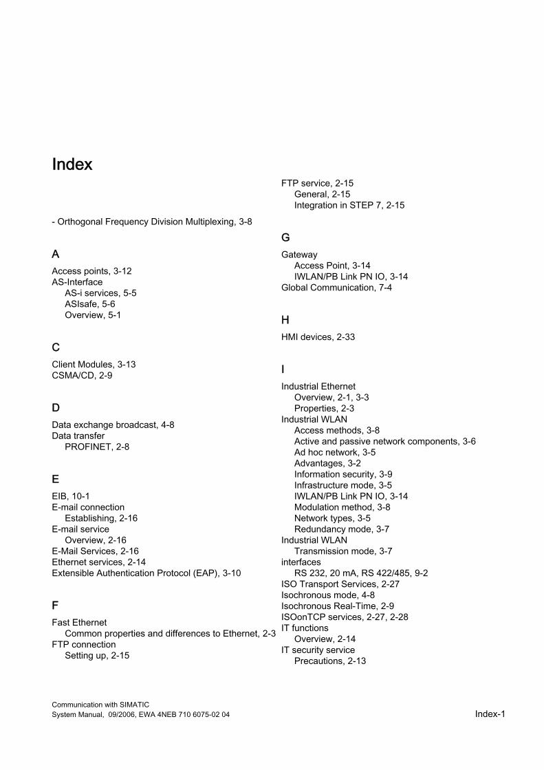
Communication with SIMATIC System Manual, 09/2006, EWA 4NEB 710 6075-02 04 Index-1
Index
- Orthogonal Frequency Division Multiplexing, 3-8
A Access points, 3-12 AS-Interface
AS-i services, 5-5 ASIsafe, 5-6 Overview, 5-1
C Client Modules, 3-13 CSMA/CD, 2-9
D Data exchange broadcast, 4-8 Data transfer
PROFINET, 2-8
E EIB, 10-1 E-mail connection
Establishing, 2-16 E-mail service
Overview, 2-16 E-Mail Services, 2-16 Ethernet services, 2-14 Extensible Authentication Protocol (EAP), 3-10
F Fast Ethernet
Common properties and differences to Ethernet, 2-3 FTP connection
Setting up, 2-15
FTP service, 2-15 General, 2-15 Integration in STEP 7, 2-15
G Gateway
Access Point, 3-14 IWLAN/PB Link PN IO, 3-14
Global Communication, 7-4
H HMI devices, 2-33
I Industrial Ethernet
Overview, 2-1, 3-3 Properties, 2-3
Industrial WLAN Access methods, 3-8 Active and passive network components, 3-6 Ad hoc network, 3-5 Advantages, 3-2 Information security, 3-9 Infrastructure mode, 3-5 IWLAN/PB Link PN IO, 3-14 Modulation method, 3-8 Network types, 3-5 Redundancy mode, 3-7
Industrial WLAN Transmission mode, 3-7
interfaces RS 232, 20 mA, RS 422/485, 9-2
ISO Transport Services, 2-27 Isochronous mode, 4-8 Isochronous Real-Time, 2-9 ISOonTCP services, 2-27, 2-28 IT functions
Overview, 2-14 IT security service
Precautions, 2-13
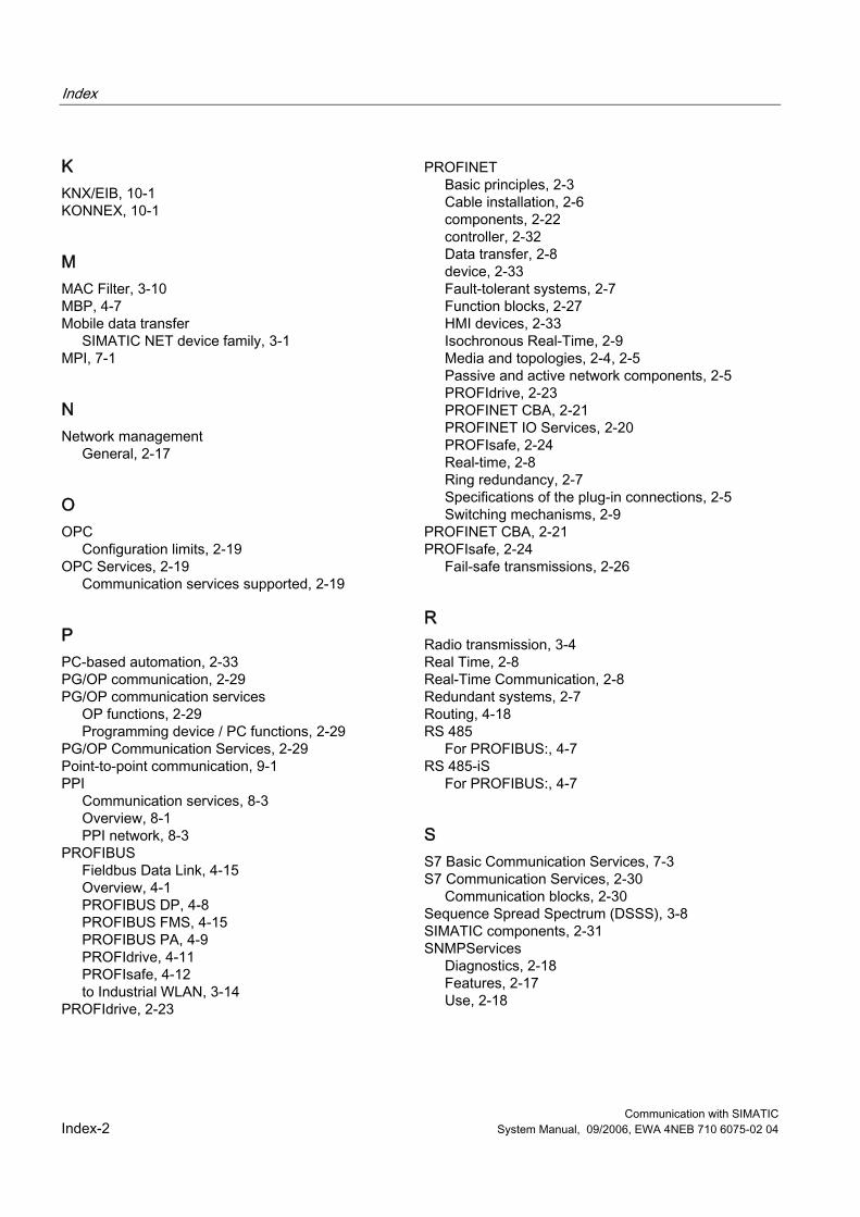
Index
Communication with SIMATIC Index-2 System Manual, 09/2006, EWA 4NEB 710 6075-02 04
K KNX/EIB, 10-1 KONNEX, 10-1
M MAC Filter, 3-10 MBP, 4-7 Mobile data transfer
SIMATIC NET device family, 3-1 MPI, 7-1
N Network management
General, 2-17
O OPC
Configuration limits, 2-19 OPC Services, 2-19
Communication services supported, 2-19
P PC-based automation, 2-33 PG/OP communication, 2-29 PG/OP communication services
OP functions, 2-29 Programming device / PC functions, 2-29
PG/OP Communication Services, 2-29 Point-to-point communication, 9-1 PPI
Communication services, 8-3 Overview, 8-1 PPI network, 8-3
PROFIBUS Fieldbus Data Link, 4-15 Overview, 4-1 PROFIBUS DP, 4-8 PROFIBUS FMS, 4-15 PROFIBUS PA, 4-9 PROFIdrive, 4-11 PROFIsafe, 4-12 to Industrial WLAN, 3-14
PROFIdrive, 2-23
PROFINET Basic principles, 2-3 Cable installation, 2-6 components, 2-22 controller, 2-32 Data transfer, 2-8 device, 2-33 Fault-tolerant systems, 2-7 Function blocks, 2-27 HMI devices, 2-33 Isochronous Real-Time, 2-9 Media and topologies, 2-4, 2-5 Passive and active network components, 2-5 PROFIdrive, 2-23 PROFINET CBA, 2-21 PROFINET IO Services, 2-20 PROFIsafe, 2-24 Real-time, 2-8 Ring redundancy, 2-7 Specifications of the plug-in connections, 2-5 Switching mechanisms, 2-9
PROFINET CBA, 2-21 PROFIsafe, 2-24
Fail-safe transmissions, 2-26
R Radio transmission, 3-4 Real Time, 2-8 Real-Time Communication, 2-8 Redundant systems, 2-7 Routing, 4-18 RS 485
For PROFIBUS:, 4-7 RS 485-iS
For PROFIBUS:, 4-7
S S7 Basic Communication Services, 7-3 S7 Communication Services, 2-30
Communication blocks, 2-30 Sequence Spread Spectrum (DSSS), 3-8 SIMATIC components, 2-31 SNMPServices
Diagnostics, 2-18 Features, 2-17 Use, 2-18

Index
Communication with SIMATIC System Manual, 09/2006, EWA 4NEB 710 6075-02 04 Index-3
T TCP/IP service, 2-26
U UDP services, 2-28
Transmission reliability, 2-28
W Wi-Fi Protected Access (WPA), 3-9 Wired Equivalent Privacy (WEP), 3-9 WPA2 und Advanced Encryption Standard (AES), 3-9

Index
Communication with SIMATIC Index-4 System Manual, 09/2006, EWA 4NEB 710 6075-02 04
S_01_48en.FH10 Wed Apr 19 09:23:24 2006 Seite 2
Probedruck
C M Y CM MY CY CMY K
������������� ��������������������
�
����������� ��������� �� ����� ���� �
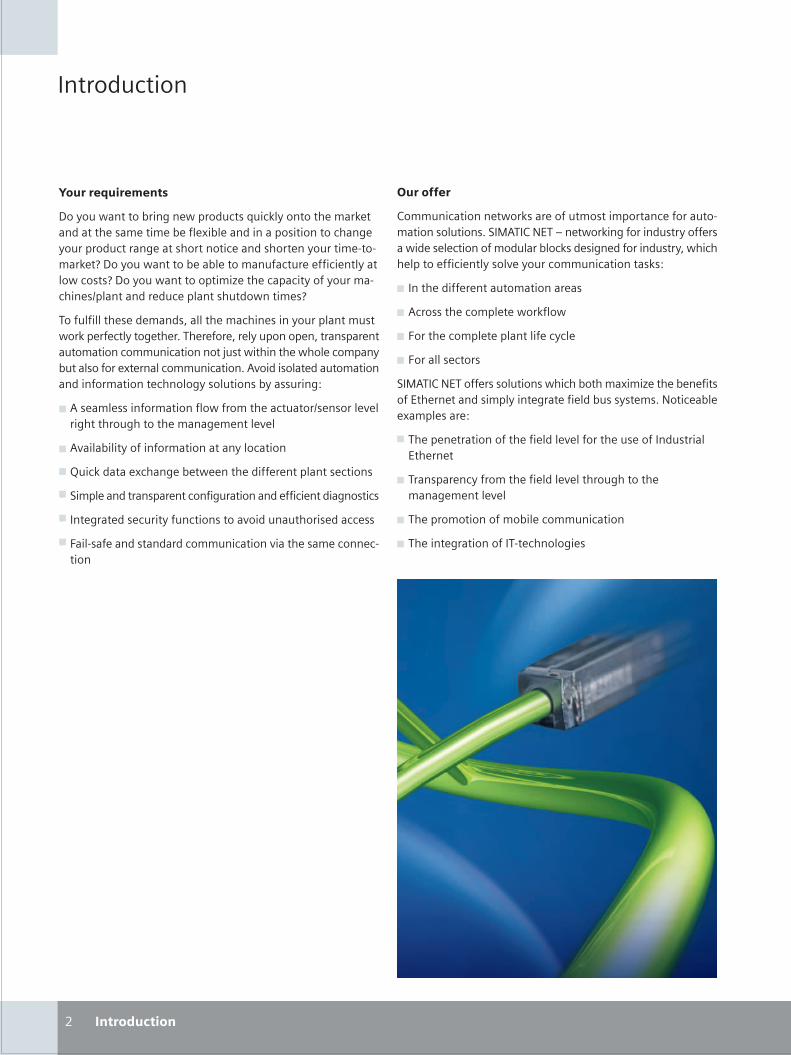
S_02_03en.FH10 Wed Apr 19 09:16:57 2006 Seite 1
Probedruck
C M Y CM MY CY CMY K
�����������
���������������
������ �������������� ��������������������������������������������������������������������������������������������������������������������������������������������������������������� �������������������������������������������� �������������� ������������������������������������������������������������������������ �������
����������������������� ���������������������������������� ����������������������!���������� ��������������� ��������������������������������������"���� �������� ���������������������������������������������!�#$����������������������������������������������������������������%
& #����������������������� ����������������������������$�����������������������������������$��
& #$�����������������������������������
& '��������������������� ������������������������������
& (������������������������������������������������������
& ��������������������������������$���������������������
)���������������������������������$���������������������
��������
*�������������� ����������������������������������������������������!�(�+#��*�,-��.���� �������������������������� ������������������������������������������������� � ������������������������$������������������������%
& �������������������������������
& #������������������� ������
& )�������������������������������
& )��������������
(�+#��*�,-������������������ ������������������������������-�������������������������������������������!�,��������������������%
& �����������������������������$���������������������������-�������
& �����������������������������$������������������������������$��
& ���������������������������������
& �������������������������������
/ ����������
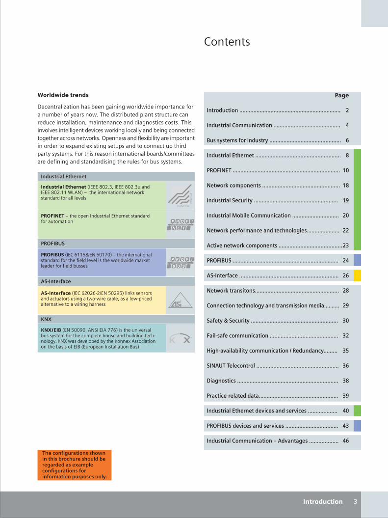
S_02_03en.FH10 Thu Apr 20 10:01:53 2006 Seite 2
Probedruck
C M Y CM MY CY CMY K
*�������
0
����������������������������������������������������������������������������
������� �������� ����������������������������������������������
������������������������������������������������������������������
������� ����������������������������������������������������������������
�����������������������������������������������������������������������������
�������������������������������������������������������������������
������� � ������������������������������������������������������������
������� �!�"��������� ���������������������������������
�������������� ��� ����������#�����������������������
$��%�������������������������������������������������������������
������& ��������������������������������������������������������������������
$ '������ ������������������������������������������������������������������
��������� ������������������������������������������������������������
�����������������#� ���� ���������� ����������
����( ��������������������������������������������������������������
� �'� ��������� �����������������������������������������������
)#�' % � "���������� ���*������ ������������
��$&�����������������������������������������������������������������
+ #�����������������������������������������������������������������������
�� ����'��� ���� � ���������������������������������������������������
������� �����������%��� �����%����������������������
������& ��%��� �����%�������������������������������������
������� �������� ���,$�% �� #���������������������
�������������������
����������������������������� ���� ������������������������������������ !��������������������������������������������������� �������������������������������!�����$��$���������������$���� ��������������������������������������������������� ����!�1����������������������������������������������������������������������������������������������������!�)����������������������������������������������������������������������������������������������!
����������
������������������2�---�34/!0 ��---�34/!0������---�34/!55�67#,8�.��������������������� ����������������������$���
������� ���������
�� ������2�-*�955:3�-,�:45;48�.����������������������������������������$��������� ���� �������������������������������
������&
�� ���� �.��������������������-�����������������������������
!�"���������2�-*�9/4/9�/�-,�:4/<:8����������������������������������� �� �������� �������� ��������������$������� �����������
#�$%����2-,�:44<4 �#,(��-�#�;;98���������$�������������������������������������������������������������!�=,>� �����$��������������=������#�����������������������-�?�2-��������������������?��8
$ '������ ��
-�.
/
0
1
2
34
32
35
/4
//
/6
/0
/1
/2
/5
64
6/
67
61
62
65
04
06
01
�������#�� �������������"�������������"���# ���� ��8 ��������#�� ������������ ����������������
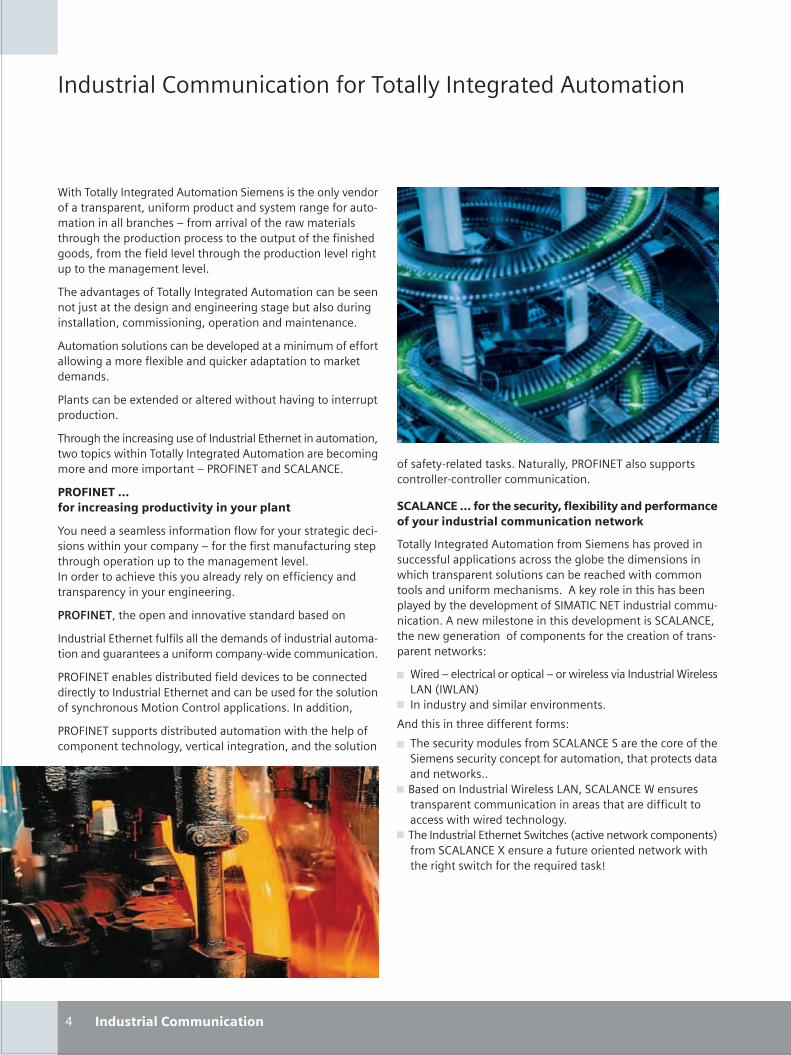
������������� ���� ��������������� � �������� ����� ����������������� ��������������������������� ������ ���������������������������� ��������������������� �������� �������������� ���������������� �������� ������������� ������� ��������������� ��� �� � ����������� ������������ � �������������� ������ � ��� � �
�� ��������� ������������� ���� ������������������ �� ����� ��������� �� ��������� ���� ��������� �������������������������������������������� ���������������� ���� �
������������������������� �� � �� ������������������ ����������������� �� !�� �����"���# �������������������# �� ������
$���������� � !� �� ������� � ����������������������� ����������������
���������� ����� �������� ��������������%�� �� ������������������������������������������ ���� ��������������� �� ��������� �������� �������������$&'(�)%�������*�+�)*%�
���������� ��� ������� ��������������� �����
,���� ����� �� �������������������������������� ����� ����������������������������������� ����������������������� ����������� ��������������� ������ � ��� � ������� ��������� � ����������� ���� ���� ����� �������������� ���������� ���� �����
������������ ��� ��������������� ������������� ����
����������%�� �� ������������ �� ������������������������������������������ ���������������������� ���������������
$&'(�)%�� ��� ����������� ���� ��� ��� ������ ����� �� ���� ����������������%�� �� ����������� ��� �������� ����������������������-������*�������������������������������
$&'(�)%�������������������� �������������������� �� ���������� ���� ��������� ��������� ��������������� ��������
����������*������������������������� ���� ������������
. ������ ����������������
������ ��� �� �����#���)�������$&'(�)%�������������������� �������� ����������������
��� ����!�� �"����� ���#���$�%���������� �� ���������� ������ �������������������&� '
�������� ���� �������������������� � ����������� �������� �������������������������� ���� ��� ���� ����������������������� ����������������� �� ��� ������������������������������� �������������# ��� �������������� ��� ������ �� � ��� ��������-���*�)%������������������������������� ���� ���� ���������� � ��� �������*�+�)*%��� �� ��� � ����������������� ���������� ��� ������������������ ���� ����#�/
0 ��� ���� ������������������������� �������������������� ��+�)�1��+�)2
0 ���������������������� ������� ����
��������������� ����� � ��������/
0 �� �� ���������� ��������*�+�)*%����� ��� ���� ������ �� � ���� ���������� ���������������������������� ������������� ����#���
0 3�� ������������������ ���+�)���*�+�)*%��� ���� ��������� ���������������������� ���������� ��������������� ����������� ��� �������
0 �� �����������%�� �� �������� ��1����� �� ����#������� ���2������*�+�)*%�4� ���� �������� ���� �� ��� ����#������� �������������������� �� "��� �����#5
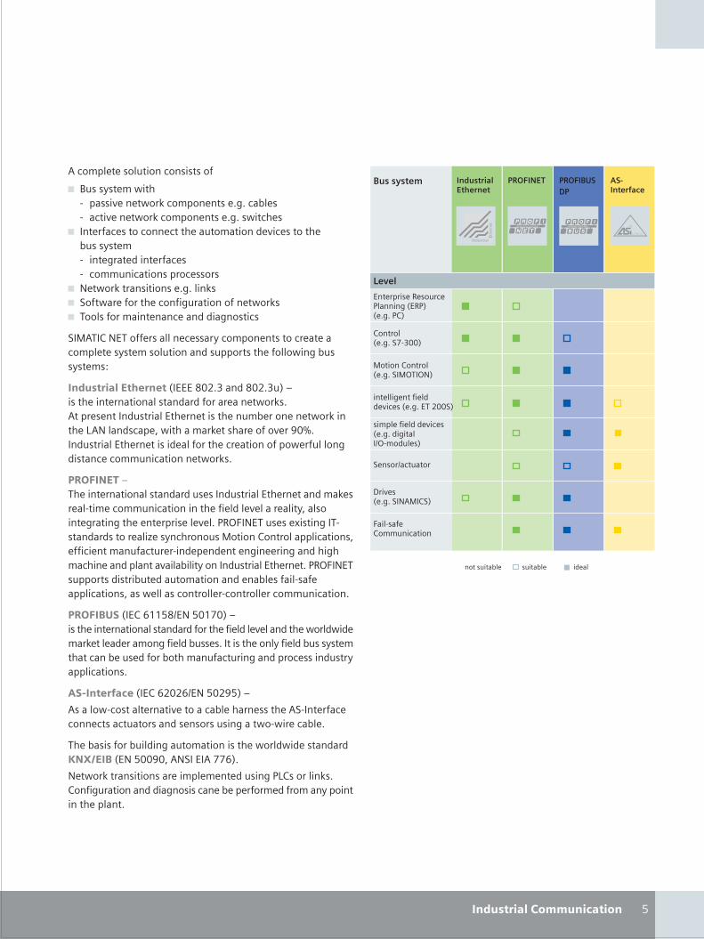
������ � ��������������������
0 3������ ������� ������ �� ����#������� ���� ������� �� ����� �� ����#������� ���� ���������� �
0 ��� ���� ��������� ����� ������������� ��� ������� ������� �� ��� ���� ����� ���� �� ������������������� �����
0 ) ����#������������� ������#�0 ������� ������� ������������������� ����#�0 �������������� ���� ����������������
��-���*�)%����� ������ � ����������� ��������� �� ������ � ���� ������������������������� ��������������� ��/
������ �����"� ���1�%%%�678�9�����678�9�2������� ���� ������������������������ ��� ����#������� � �������������%�� �� ������� ����� ���� �� ����#����� �+�)�������� ������������# ������ ������ ��:7;�����������%�� �� ������� �������� ��� ������������ �������������� ���������������� ����#��
������������ ���� �������������������� ������������%�� �� ��������# �� ����� �������������������� ��� �� � ���� ����������� ���������� � �� ����� � � ��$&'(�)%���� �� !������������������������ ��< ������������-������*������������������ ����� ������������� ����� � �� ��� ���� ������������������� ���������������������������������%�� �� ���$&'(�)%������������������� ����������������� ��� ��������� ����������������� ���������� �������� ����������������
�����()��1�%*�=>>?6@%)�?7>A72������� ���� ������������������������ ��� �� � ������� �������� ���# �� �� ���������� ������ ����������� ������ ��������� ����������� ��� ��������������������������������� ����������������������
��*���� ����1�%*�=878=@%)�?78:?2��
��������������� ������ ��������� ����� ����� ������� ���� ���� ������������������� ��������������������� ���� �
�� ����������������������������������� �������� ���������+�,-��(�1%)�?77:7���)���%���AA=2�
) ����#��������������� ���� � �� ��������$+*�������#��*������������������������������ �� �� ����� �������������������� ������
?������ ����������������
%�� ����� �& ����� $�������1%&$21 ����$*2
*�����1 �����A�9772
��� ���� ������������
���������
�����������������
��������
B��� �1 ������)�-�*�2
���� ��� ��� ��� �1 �����������@'����� �2
� ����@��������
��� �� ����� �� ��� ��1 ����%��877�2
-������*�����1 ������-'��')2
���������� ������ �� �
�� ��
(������ *������������
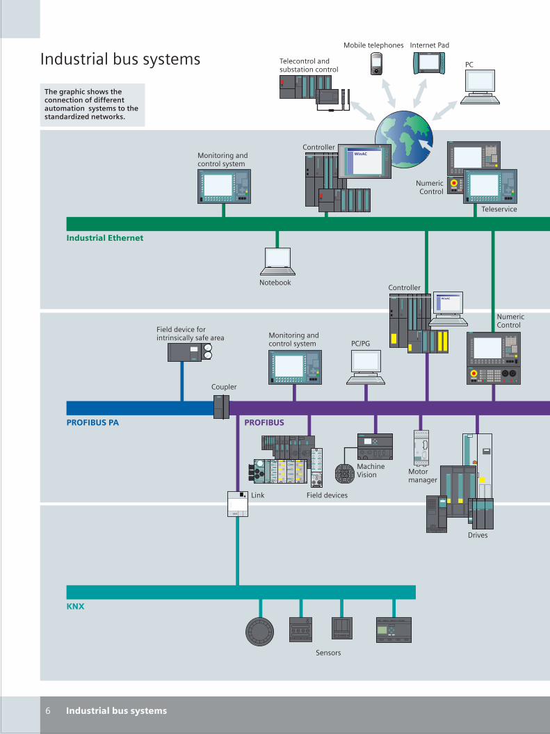
S_06_07en.FH10 Wed Apr 19 09:28:04 2006 Seite 1
Probedruck
C M Y CM MY CY CMY K
�������������� �����
�
������������� ���������������������������������������������������������������� �����
����������� �����
�������������������
����������������������������
��������������� �����������
��
��������
��������
�������������������������� ����
������������ ����������� �� ����
��������������������� ����
����������
��������
������
!���
"������
����������
#�����
������������
������$�����
�������������
�������������
��������������������
���
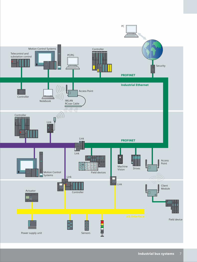
S_06_07en.FH10 Wed Apr 19 09:28:04 2006 Seite 2
Probedruck
C M Y CM MY CY CMY K
%
�����������
��������
"������
��
�����
��������������" �����
����������������������������
�������������" �����
��������
!���
&������
��'������� ����� "������
������������
������$�����
&����������
����������
�����������
#�����
��������
��������
!���
!���
&�����������
�������� �(!&�)��*����
!���
��������������������
!���
�������
�������
����������� �����
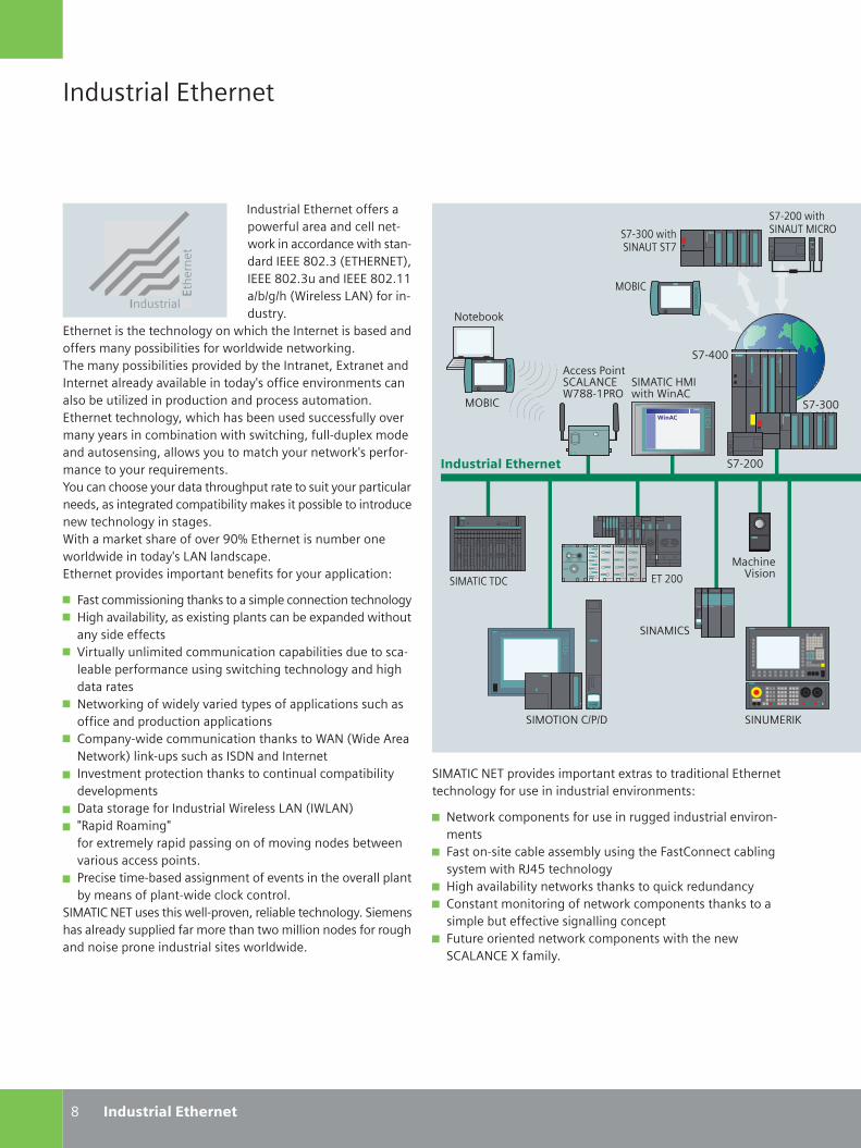
������
����� �����������
����� �������������������������������������������������� �������������� ���������������������������� !��"#������������������������$$�%&%'%���( �����)*!"����� �����+�
��������� �������������'+������ ���������������� �&�������������,��+��� & � � ������������ ���������� �'�����,��+��� & � � �����- ����&+�������������#��.�������������������������+��-� ��&��� ������+/���� �����- ���,�����������&��� � 0��� �������� ����������������,�� ��������������������'+#��� ������&�������������+��-��,��+�+���� ����,& ��� ���� ���� ��� �'#���������.�,������������ �'#�������+�����,�����+����������/��������,��������+�����1 ��,����2������������+������������'������������ ��+������� ��������#��� ���'��������,��� & � �+�,���� ���� &������ �������������������'+� ����'��( �����,���������������-���3�4���������� ��,&������������ ��� ������+/�)*!����������������������- ��� ,��������&���� ������+������� ��� ��5
6�����,, �� �'������������ ,����������� �����������'+� '���-� ��& � �+#����. � �'�����������&���.�������� ������+� ���������7 �����+��� , ������,,� ��� �������& � � ��������������&���������,����� �'�� ��� �'���������'+������ '����������!������ �'����� ���+�-�� ����+���������� ��� ���������� ������������� ������� ��� ��8�,���+�� �����,,� ��� ������������(*!��( ���*���!������"�� ������������9!���������������-��,����������� ���������������� ������,��� & � �+��-����,���9��������'����������� ���( �����)*!���()*!": �� �� ��, �':�����.���,��+���� ���� �'�������,�- �'������&������-�� ��������� ���;��� ��� ,��&����� '�,��������-���� �������-�����������&+�,�������������� �����������������
��<*��8�!������� ���������-��#���� �&�����������'+��� �,�����������+���� �������,�������������, �� ��������������'������� �������� ���� ��� ��������� ���
<��� ��7 ��
<=>�8
��<*��8��98
�������� ����!*?�����
����������� �����
*����;� ���8*)*!8�(����$; =
������
���@��
��<*��8��<�� ���( �*8
�
�������� ����!*?��<�8 =
����������� �����
������
��<*��8�!������- ��� ,���������.����������� � ���������������������'+������� �� ���� �����- ���,���5
!���������,������������� ���''��� ���� �����- ����,���6������ �����&�����,&�+� �'�����6��8���������&� �'+��,�� ��� A@B���������'+� '���-� ��& � �+������������������1 �����������+8�������,�� ��� �'��������������,����������������� ,����&�������� -�� '���� �'��������6������ ����������������,�������� �����������8*)*!8��C���, �+�
!���&���
<=>�8
��<=��=!�8%;%9 ��!?<� �D
��!*<�8�
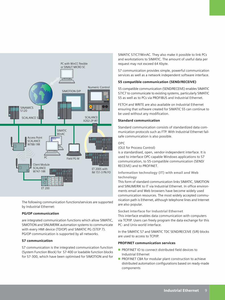
��<*��8���%8�%( �*8�����+�����,���� ���� &������� ���;8����������� ��������<*��8�������,���������������������1���,�+������.�����E@�D&+���
�����,,� ��� ������- ��� ,���#�����������,,� ��� ����- ���������������������� ������������������� ���������
���������������������������������������
�B���,��� &�����,,� ��� ������!9% �8��7�"����&�����<*��8��%8�������,,� ���������. � �'�+��,#����� �����+���<*��8�B�������������;8�- ��; =6�>?����������� ������������
6��8������( �������������-� ��&����������� �������������� �'����������������������������<*��8��B��������� �����&������ �������+�,�� � ��� ���
�������������������
�����������,,� ��� ������ ������������ 0����������,�,� ��� �����������������6�;��( �������� �������������� ��������,,� ��� ��� ������� &���
����=)������;�����8������" ���������� ��#�����#�-������ ����������� ������������� ������ ���������=;8�����&���( ��������� ��� ����������,,� ��� ��#�����B���,��� &�����,,� ��� ������!9% �8��7�"��������; =6�!���
�� ����������� ���!"���#��$�� ��������%����� ���!"�� ����,��������������,,� ��� ���� �����<*��8#���<=��=!������!?<� �D�������- ������� ������������������� �����- ����,�����,� ������(�&�&��������-��&���,��� ���+�����,,� ��� ���������������,���� ���+������������,,�� ��� �������� ���������#������'������������� ������������������������������
���&�������� ��� �������������� ������� � ������������&����������,,� ��� ���� �����,����- ���8;%�;��?������������+����'��,�����������.����'�������� ;8������?� .������� ���������
���������<*��8����������<*��8��98���!9% �8��7����% "�&�����������������������8;%�;�
���'���#�����������������(����
; =6�!����=������������� �� &����� ������- ���������� �����������; =6�!���8>*�����,������������������� ��������� �-�� �� &�������,�� ������� '��� ���&�����������+�,�����,������
���������� �'���,,� ��� ������� ��%��- ��������������&+������ �����������5
�)����������������
���� ���'��������,,� ��� ������� ����� �����������<*��8#��<=��=!�������!?<� �D����,�� ���+��,������,,� ����� ����-��+��<����- �����9%=;"�������<*��8�;F�����;��"�;F%=;���,,� ��� ��� ���������&+�������������
�*�������������
�����,,� ��� ��� ����� ���'��������,,� ��� ������� ����+��,�6��� ���>����"���������@�����������&������� ���&��������������#��� �����-��&������� , ���������<=��=!��������
;8�� ���( �88����. &�������!*?��<�8 =��8
;8 6 ����;F�<
��<*��8( �*8
*����;� ���8*)*!8�(����$
8� ����<�����8*)*!8�(�@��$
��!*<�8��$��
3
������
�8*)*!8�C�����;�� �
��������� ���<�$B$���;!�6=
����������� �����
��<=��=!�9%;
�8*)*!8���
!,�� ��8������
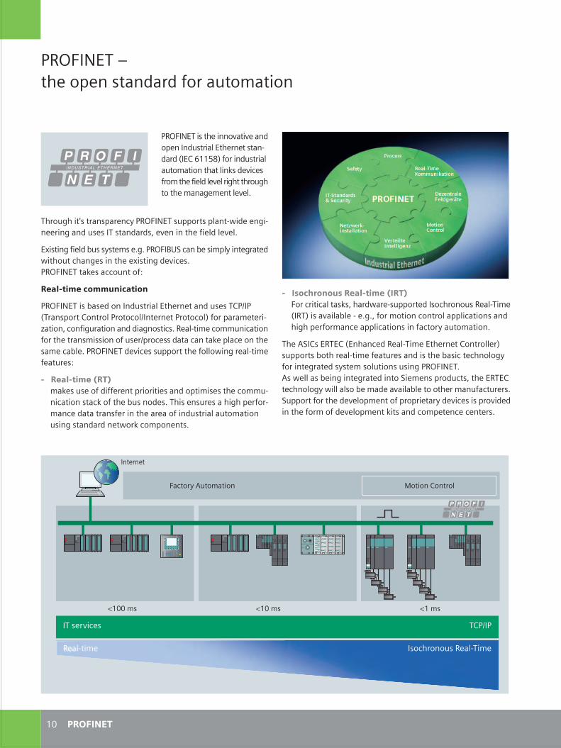
S_10_11en.FH10 Thu Apr 20 10:12:57 2006 Seite 1
Probedruck
C M Y CM MY CY CMY K
���������� �� ����������������������
��
� ������������ ����������������������������������� ������� ������������� �� ��� !���"���#����$� %&%����������������������������������&�� �������� ��������������������'����������%
�� ()�*�����*!������ �� �� ��� ��� �� �*������� �"��������$���� �� ��� � ���� �������� $����� ������&'������ &��� ��'�� ��������������&��������%(�� ����$ ��&��� &��� �����)� � ������������� ����*� ������&'��������$ ��� �#����$� ����� ����������� ��%)����������� � # ���� ���������� ���'� #�� ������#�� ����� ������� # ���� ������������� � �� � �� ��%
������������ ����#���# ����� �������������� �� ����� ����!��*+��,-"��������������������������������� #�� ������� �� ��� # ���&�������&����� ����& � ��� # �%
�����&���.��������� ��'��������������������� ��� �&� � ���&����� ������������� # ����� �� ��� # �%
�/�����&�� ��$���'�� �� %&%�����01)���$ �����'��� &��� ������������& ����� /�����&� #�� �%����������� ����������2
�� ������������� ����
����������$�� ���������������� �� ������ ��*�3��!���������*��������������3��� �� ���������"�������� � �� 4�����������&�������������&�������%� �� ��� ������������������ ���������������� �3���� ������������ ���� ���� ��� ��$� %��������� #�� ���������� ��������&� �� ��� � ���� �2
� �� ������������� ��� ������ � ���������� ����������� ��� ����� ����������������� $����� �%���� ���� ����&�� ���� ���� ���������� ����� �� ���������������������������&��������� ����������� ���%
��������
��� �� �
5�����
������'(��������� 6�����*������
5���� 5���
��� �#�� � �*�3��
� �� ��� ������������ �� ���
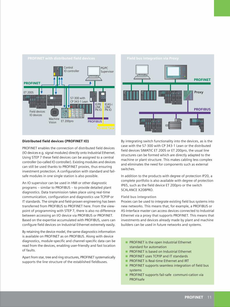
C M Y CM MY CY CMY K
����������������������������������
�������� ��$� ��� ���� �������������$�� ��� ��� #�� �!��� #�� � %&%��&�������� �"��� ���'����������������� �� �%1���&)���7�� � �� ��� #�� ����$ ����&� ����� ������������� �!�� ���� ����������� �"%�/�����&����� ����� #�� ���������$ �� ��������������������/� ������ ������&��# ��� ������ �����%(�����&�������������������������� ��� ����� ����� ���&� ������������������$� %
(������ �#�������$ �� ���86������ ����&���������&������������������01)�����#�� � ���� ���������&�������%9������������������ ����� ����&� �� ��� �������������������&�������������&��������� �*�3���������������%�� ����� ����� �� ���# � �&�� ���&���$ ������� �� ����������01)����������� � %������ #� � ����������&������&����)���7��� � ������������ � �� $ �� ���� ����&���3�� #�� #�������01)����������%0�� ����� /� ���� ��������� ����������01)��� ����������&�� �� ��� #�� ���������������� �� � /�� � �' ����'%
0'� ������&�� � #�� ��� ���� ��� ���&���������������������#����$� �������������������01)%(���&����� #�� ���&������������� �� ������������� � �� ������������$ � �������� � #�� �� ��$���&�� � ��� ���'�����������������������%
(��������������� ������&�������� �����������'�� ��������'���������� ��� �������� ���� ���$���� ��� ��$�� �%
�:3�*)�� �#����
�� ��� #�� ���� #�� �
*���������������� �
��3�0;��<����
����������=�����
��=��)
����������������������������������
���
����� !"
��
0'��� &�����&������������������'������ � #�� �������� ��� ������ )7 >������*�>?> �; ������ ������$�� ��� ��� #�� �)�6(��*��=��)����=�������� �������� �������� ����$ ���� �������� ��� ���'����� ����� ������ ��������������� %������� ���$���&� ������� /��� ������� ��� � ���������� ��������� /� ���������� �%
�������������� ������������� &� ������ �������=�������� � ����������������#����$� ����� &� ������ �������+,��������� �� ��� #�� ��=��������� ������)*(;(�*�@=�-���%
�����������#� �������/� ����$ �� ������ &��� /�����&�� ��$���'�� ������� �� ������%����� ����������� /���� �������01)��() ��� ���� ���� ������� ��� #�� ����� �� ���������������� �� �#������/'��������������������%����� ���������# ��� ������� #�� ���� ��'��� $'�������������� $���� �����$ �� �������� � ����������'�� ��%
6����� A�����
��������
��3() �;��<����
����������
�����������#� ������ ���$%
)7 >������*�>?> �; ��
����������������
������������ �� �������������� �� ��������������������������������$�� ���������������� �� ����������� ��*�3��������������������������� �� ��� ��� �� ������������������������ ��� ����� &���������� ��$���'�� ���������������������� ��� ������� ������#����������
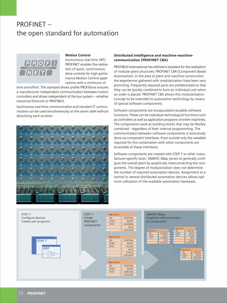
C M Y CM MY CY CMY K
����������������
���������
� ���������
���������� �����
������ �
���������������
� ���������
��������� � �
����
������ �
���������
� ���������
����������� ����������
������ �
���������������������
� ���������
��������� � �
����
������ �
���������
��������
� ���������
���������� �����
������ �
���������������
���������
� ���������
����������� ����������
������ �
����� ��!��"������ ���#$�#���"%
�!������&���"�!�#����"�#�#'��#$�#���"%
����� ��#�'�()!��*�+���%�!��"��)%�!��!#(!�$%
���
����� ���,"���#����%"��*�!*�'#!��)"#$�"�#�
�������
�� �����������%#��!#�#)%�!��&-"�$��.���/����� ������0&�%�"���!��&�%�-"�#��#'�1)��23�%4���!#�#)%*!�+���#�"!#&%�'#!���(����!'#!-$������#"�#���#�"!#&����&�-��"�#�%�5�"����$���$)$�#'
"�$����*��''#!"6�����%"��*�!*�*!�+�%��!#'�&�������*!�+����%)!�%��$��)'��")!�!���*����*��"��#$$)����"�#��0�"5����$#"�#��#�"!#&&�!%���*�*!�+�%���*����*��"�#'�"���0)%�%4%"�$�,�5��"��!��*)%"!��&��"��!��"�#!���������6
�%#��!#�#)%�!��&-"�$���#$$)����"�#����*�%"��*�!*�����#$$)-����"�#������0��)%�*�%�$)&"���#)%&4�#��"���%�$����0&��5�"�#)"*�%")!0��(��������#"��!6
� ��� ������ ����� �������������� ������� ��������� ��� ������������� !"
�����������"�!��"�#��&���%�*�'���*���%"��*�!*�'#!�"���!��&�7�"�#�#'�$#*)&�!��&��"�%"!)�")!�%������� �������.�#$�#���"���%�*�)"#$�"�#�/6����"����!���#'��&��"���*�$��������#�%"!)�"�#�"����8��!�����%�(�"��!�*�5�"��$#*)&�!�7�"�#����+��0����+�!4�!#$�%��(6��!�1)��"&4�!�1)�!�*���!"%��!���!�'�0!���"�*�%#�"��""��4�����0��1)��2&4��#$0���*�"#�'#!$������*�+�*)�&�)��"�5������#!*�!��%��&���*6������ ��������&%�"��%�$#*)&�!�7�"�#��#����"�"#�0���8"��*�*�"#��)"#$�"�#��"����#&#(4�04�$���%#'�%�����&�%#'"5�!���#$�#���"%6
�#'"5�!���#$�#���"%��!�������%)&�"�*�!�)%�0&��%#'"5�!�')��"�#�%6����%������0����*�+�*)�&�"����#&#(���&�')��"�#�%�%)���%��#�"!#&&�!%��%�5�&&��%����&���"�#���!#(!�$%�#'���"�!��$������%6�����#$�#���"%�5#!2��%�0)�&*��(�0&#�2%�"��"�$�4�0��'&�8�0&4�#$0���*�-�!�(�!*&�%%�#'�"���!���"�!��&��!#(!�$$��(6�����#$$)����"�#��0�"5����%#'"5�!���#$�#���"%��%��8�&)%�+�&4*#���+����#$�#���"���"�!'���%6��!#$�#)"%�*��#�&4�"���+�!��0&�%!�1)�!�*�'#!�"����#$0���"�#��5�"��#"��!��#$�#���"%��!�����%%�0&���"�"��%����"�!'���%6
�#'"5�!���#$�#���"%��!���!��"�*�5�"������� �#!�#"��!�$��)-'��")!�!-%����'���"##&%6��������������%�!+�%�"#�(���!�&&4��#�'�-()!��"���#+�!�&&��&��"�04�(!������&&4���"�!�#����"��(�"����#$-�#���"%6�����*�(!���#'�$#*)&�!�7�"�#��*#�%��#"�*�"�!$���"����)$0�!�#'�!�1)�!�*��)"#$�"�#��*�+���%6��%%�(�$��"�"#�����"!�&�#!�%�+�!�&�*�%"!�0)"�*��)"#$�"�#��*�+���%��&%�#�"�-$)$�)"�&�7�"�#��#'�"����+��&�0&���)"#$�"�#����!*5�!�6
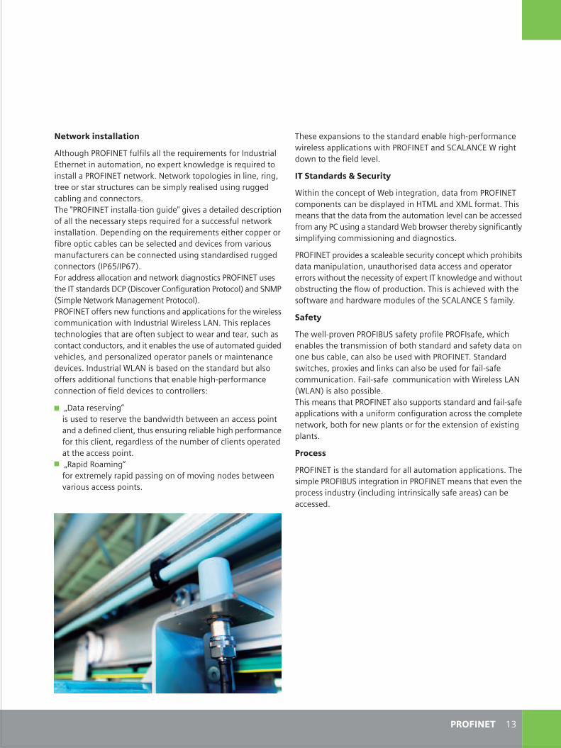
C M Y CM MY CY CMY K
��������
���%���8���%�#�%�"#�"���%"��*�!*����0&����(�-��!'#!$����5�!�&�%%����&���"�#�%�5�"������� �����*������ ���9�!�(�"*#5��"#�"���'��&*�&�+�&6
��#���������$�#���� �%
9�"����"����#����"�#'�9�0���"�(!�"�#�3�*�"��'!#$������ ���#$�#���"%�����0��*�%�&�4�*�����������*�:���'#!$�"6����%$���%�"��"�"���*�"��'!#$�"����)"#$�"�#��&�+�&�����0������%%�*'!#$���4����)%��(���%"��*�!*�9�0�0!#5%�!�"��!�04�%�(��'����"&4%�$�&�'4��(��#$$�%%�#���(���*�*��(�#%"��%6
����� ����!#+�*�%���%��&��0&��%��)!�"4��#����"�5������!#��0�"%*�"��$����)&�"�#�3�)��)"�#!�%�*�*�"������%%���*�#��!�"#!�!!#!%�5�"�#)"�"�������%%�"4�#'��8��!"����2�#5&�*(����*�5�"�#)"#0%"!)�"��(�"���'�#'��!#*)�"�#�6����%��%������+�*�5�"��"��%#'"5�!����*���!*5�!��$#*)&�%�#'�"�������� �����'�$�&46
#�&��%
����5�&&-�!#+������������%�'�"4��!#'�&�������%�'�3�5�������0&�%�"���"!��%$�%%�#��#'�0#"��%"��*�!*���*�%�'�"4�*�"��#�#���0)%���0&�3������&%#�0��)%�*�5�"������� ��6��"��*�!*%5�"���%3��!#8��%���*�&��2%������&%#�0��)%�*�'#!�'��&-%�'��#$$)����"�#�6����&-%�'����#$$)����"�#��5�"��9�!�&�%%��� .9�� /��%��&%#��#%%�0&�6���%�$���%�"��"������ ����&%#�%)��#!"%�%"��*�!*���*�'��&-%�'����&���"�#�%�5�"����)��'#!$��#�'�()!�"�#����!#%%�"����#$�&�"���"5#!23�0#"��'#!���5��&��"%�#!�'#!�"����8"��%�#��#'��8�%"��(�&��"%6
�������
����� ����%�"���%"��*�!*�'#!��&&��)"#$�"�#�����&���"�#�%6����%�$�&�������������"�(!�"�#���������� ���$���%�"��"��+���"���!#��%%���*)%"!4�.���&)*��(���"!��%���&&4�%�'���!��%/�����0�����%%�*6
���'��(� �������� ��
�&"�#)(������� ���')&'�&%��&&�"���!�1)�!�$��"%�'#!���*)%"!��&�"��!��"�����)"#$�"�#�3��#��8��!"�2�#5&�*(���%�!�1)�!�*�"#��%"�&&�������� �����"5#!26� �"5#!2�"#�#&#(��%����&���3�!��(3"!���#!�%"�!�%"!)�")!�%�����0��%�$�&4�!��&�%�*�)%��(�!)((�*��0&��(���*��#����"#!%6����;����� �����%"�&&�-"�#��()�*�;�(�+�%���*�"��&�*�*�%�!��"�#�#'��&&�"�������%%�!4�%"��%�!�1)�!�*�'#!���%)���%%')&���"5#!2��%"�&&�"�#�6������*��(�#��"���!�1)�!�$��"%���"��!��#���!�#!'�0!��#�"�����0&�%�����0��%�&��"�*���*�*�+���%�'!#$�+�!�#)%$��)'��")!�!%�����0���#����"�*�)%��(�%"��*�!*�%�*�!)((�*�#����"#!%�.��<=>��< /6�#!��**!�%%��&&#��"�#����*���"5#!2�*��(�#%"��%������ ���)%�%"������%"��*�!*%�����.��%�#+�!��#�'�()!�"�#���!#"#�#&/���*�� ��.��$�&�� �"5#!2�����(�$��"��!#"#�#&/6����� ���#''�!%���5�')��"�#�%���*����&���"�#�%�'#!�"���5�!�&�%%�#$$)����"�#��5�"����*)%"!��&�9�!�&�%%��� 6����%�!��&���%"����#&#(��%�"��"��!��#'"���%)0?��"�"#�5��!���*�"��!3�%)����%�#�"��"��#�*)�"#!%3���*��"����0&�%�"���)%��#'��)"#$�"�*�()�*�*+����&�%3���*���!%#��&�7�*�#��!�"#!�����&%�#!�$���"������*�+���%6���*)%"!��&�9�� ��%�0�%�*�#��"���%"��*�!*�0)"��&%##''�!%��**�"�#��&�')��"�#�%�"��"����0&����(�-��!'#!$�����#����"�#��#'�'��&*�*�+���%�"#��#�"!#&&�!%�
@ �A��"��!�%�!+��(B�%�)%�*�"#�!�%�!+��"���0��*5�*"��0�"5�����������%%��#��"��*���*�'���*��&���"3�"�)%���%)!��(�!�&��0&����(����!'#!$����'#!�"��%��&���"3�!�(�!*&�%%�#'�"����)$0�!�#'��&���"%�#��!�"�*�"�"�������%%��#��"6
@ �A����*��#�$��(B'#!��8"!�$�&4�!���*���%%��(�#��#'�$#+��(��#*�%�0�"5���+�!�#)%�����%%��#��"%6
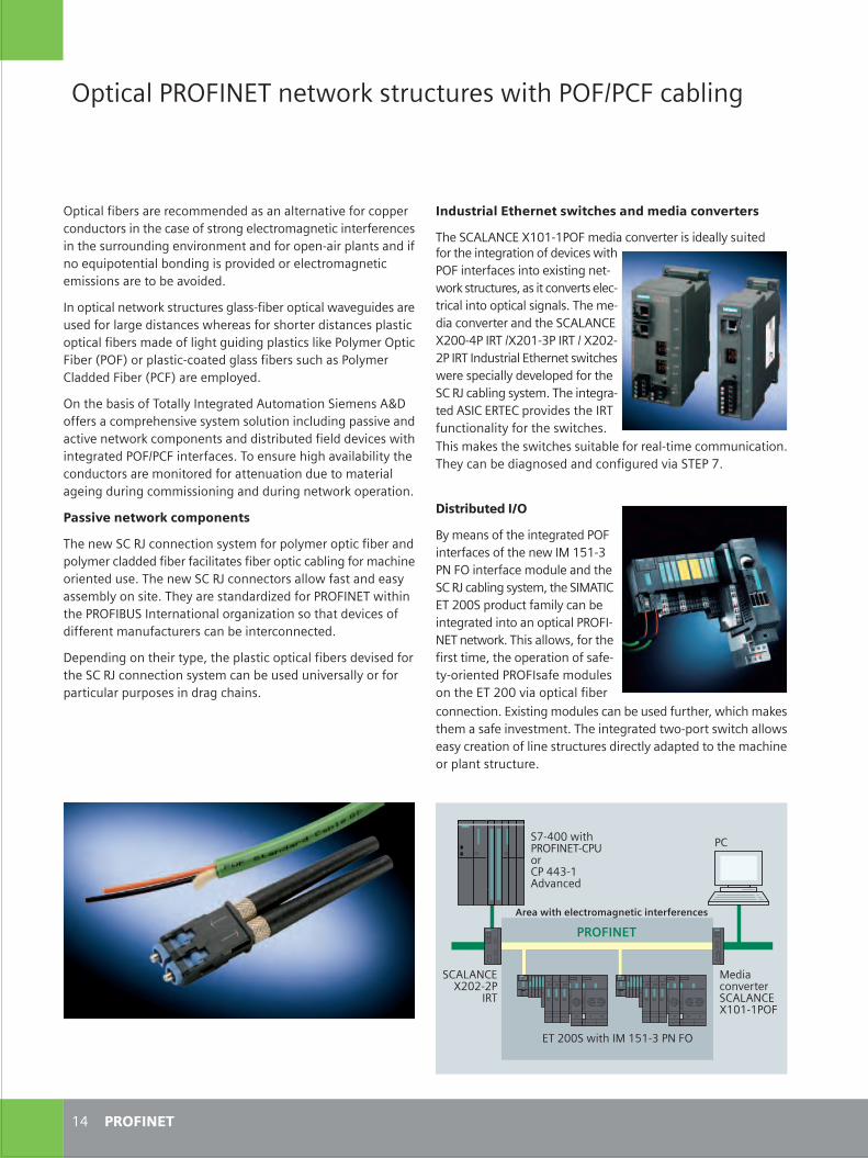
C M Y CM MY CY CMY K
����������� ����������������������������������������
�� ��������
��� ������ ���� ���� ����������������� ���
������ ! ���"�#�$����%�&������'����������&����(������&)��������������������)�&�'�����������������)�����������*����������$���������������+����������'���������$���������������������������,�����%�$&������'��������&������� ! ��"-##$������"-#�$.������"-#-$-������&��������������������������������������(�&�'�����&�)���������/����������(���%,������������$��&� ������������'�&���������)�����������(�)���������������,�����%���������������������������)�������$��%����%%���������,���(��������&�������&���&����)�����&�'�������0,
���-##��������1��2�$.� ���
�0$�##�������� ��$�3������.$� &'����&
��������������� ���������������������
1�&�����'������� ! ��"�#�$���
�
�� ! ��"-#-$-
��
��������
��������)��������������%%��&�&����������������'��)������������&��������������������)���������������%�������������)���������������������&������'����%������&�)�������$�������������&��)����4���������������&����������'�&�&�����������%��������%�������������������'��&�&,
�����������������������������������$)���������������'����&���������&�)���������&�����������������)�����������&������������������������)������%�&���)����������&��������������������(%��������������5��6�����������$�����&�������)����������������(%�����&&�&�������5��6������%���(�&,
��������������)�������(����������&� ���%���������%���� 78�))��������%��������'���(���%���������������&���������'����&����'������������%����������&�&���������&�)���&�&�'������������������&������������)����,�����������������'���������(�������&�����������%�������&�)���������������&������%��������������&��������%%������������&�&�����������������������,
��������� ����������� �
�����������/�������������(���%�)������(%���������)�������&���(%������&&�&�)�����)�����������)�������������������)���%�������������&����,������������/������������������)������&����(����%��(��������,����(���������&��&�9�&�)������ ����������������:3����������������������9��������������&�'������)&�))������%���)�����������������������������&,
8����&��������������(��+���������������������)������&�'���&�)���������/�������������(���%�����������&����'������(����)�������������������������&����������,
��� ���� �����
:(�%������)��������������&��������)������)����������1��2�$. ���������)����%�&������&�������/����������(���%+�������1 ������-##�����&����)�%��(����������������&��������������������$ ����������,������������+�)������)�������%�+����������������)���)�$�($�������&������)��%�&��������������-##�'�����������)��������������,��*�������%�&���������������&�)������+�������%�������%�����)����'���%���,��������������&����$���������������������(�����������)�����������������&������(��&����&��������%������������������������,
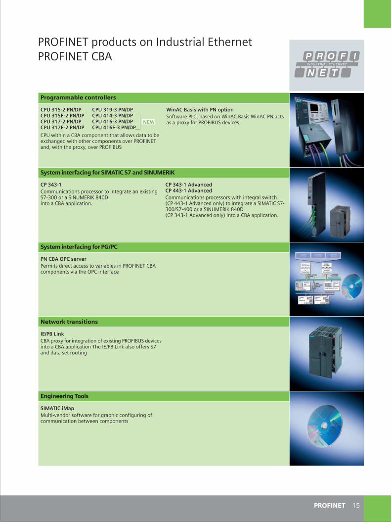
C M Y CM MY CY CMY K
���
�2
��� ������&����������&������������������� ����:
��������
��� ����������� �������
�������� ���!"� ������#�����!"���������� ���!"� ����$�$�����!"�������%� ���!"� ����$�&�����!"�������%�� ���!"� ����$�&������!"��3�����������: ���%�������������������&����������*������&��������������%���������'������ ����&+�������������*(+��'������:3�
'�����(�������������)������)������!�+�����&����;�� ��:�����;�� �� �������������*(�)������:3��&�'����
!"� ���� ��#��� �#���!�$%��&�!'���!��($���)
����$�����%%��������������������������������������*�������0$.##�������� 31��<�=�#8��������: ������������,
����$�����*+����*���$$�����*+����*��%%������������������������������������������5����.$�� &'����&����(6������������������1 �����0$.##��0$�##�������� 31��<�=�#85��.�.$�� &'����&����(6���������: ������������,
����(���������+����%����&����������������'��������������� ����: ��%��������'���������������)���
!"� ���� ��#��� �#����*��&
��!�(�,��-�: ����*(�)����������������)��*����������:3��&�'������������: ��������������������:�!����������))�����0��&�&���������������
�� ����� ���� ���
.�/������/�)1����$'��&�����)������)��������������)���������)��%%��������������������%�������
� ����� ������
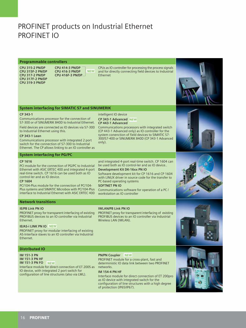
C M Y CM MY CY CMY K
���������� �������� �������������������������
�� ��������
��� ������������
������������� ���� � ��������������������� ���� ���������������������� ���� ��������������������������������������
������������������������������������������������ ��� ��������������������� ���������� ���������������
���� ����� ������������������������������������!"#$%%����!���&���'()%*���� ���������������+���� ����������������� ���� ���������!"#$%%���� ������������������������+���� ���������� ������������������,������������ -����,����������������������!"#$%%���� ���������������+���������,����.���������������������
������������� ��������� ��������������� �������������� �������������������,������������ �,����/��))$#�0 ����� ����1������������������������� ���������������� ��������!�&0���!"#$%%2!"#)%%��!���&���'()%*/��$)$#�0 ����� ����1+
����� �������������������������������������
���������� � ����������������������32������ ���������������,���0!�������)%%�� ��������� )#�������#�� ��,����+���������4���� 4��������������#����� ���� �����+������ ��2�%)#���� � �����������������������2�%)#��������� ��� !�&0���&����4�5,�����2�%)#����������������� ���������������,���0!�������)%%
�� ��������� )#�������#�� ��,����+����%)���4���� 4��������������#����� ���� �����++������������ !��� ���""���#$!���,��� ����� ���.������������� ����%),���6���7 ��������������� �������������������#4��� ������������� �%$�&'&���#$�� ��������������,�������������������2,��.���������������������
����� ���������������!"��
#'��(��!�)���#$����������5����������������������������5�����������8�! ��������������������������� ���������������+
#'��%�!��# ���#$����������5���� � ������������������5������0!#������������������������������������ ���������������+
#*����(��!�)���#$����������5����������������������������5�����������8�! ��������������������������� �������9�������60�/�960�1+
���#$����������
#+��������#+���������,�#+����������$��������� � ������ �������������������-%%!���� �����:,������������ -����,������������������������������������/�������6961+
������-���.�������� � ������������#����:������ ���� ��������� ������.4��,����,������������,��.�+#+��� � ���,���������� � ������ �������������������-%%������ �����,������������ �,���������������������������������������,�������� ����������������/���;2���"1+
%�����&������
��'
��'
��'
��'
��'
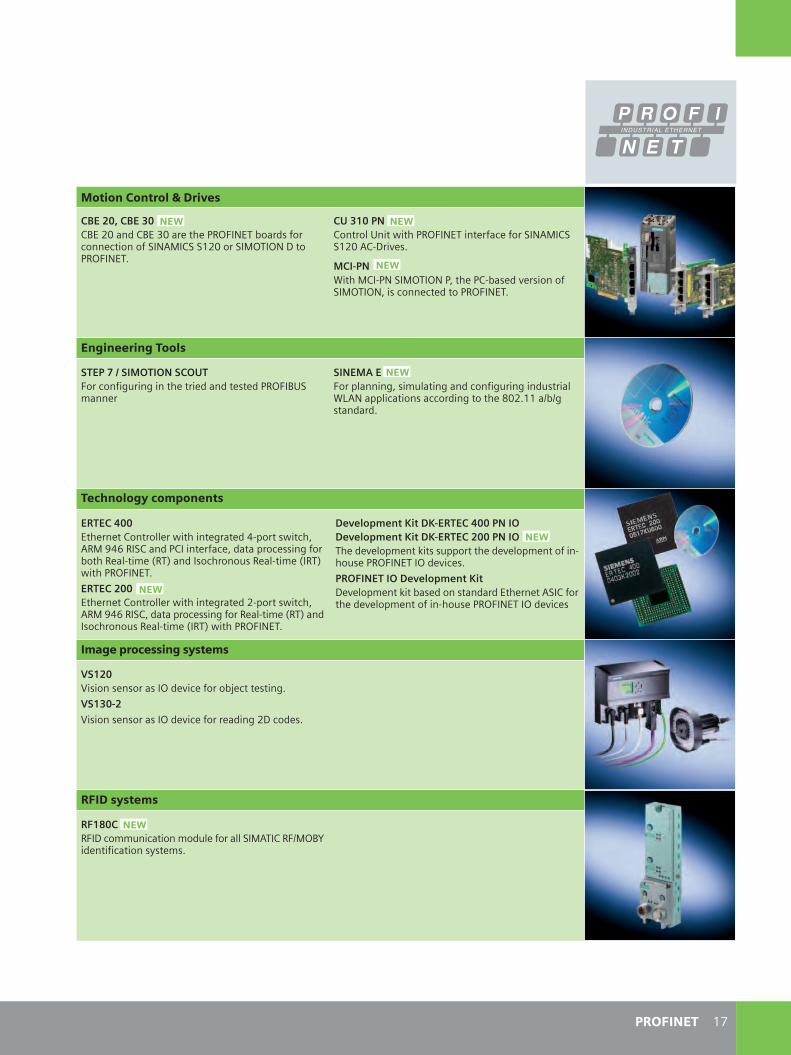
C M Y CM MY CY CMY K
�"��������
����������(�%�)��
�('��/��('����8�-%�� �8�$%��������������4��� ����������������!��0&��!!�-%��!�&�����*����������+
�������������������,�����������������������!��0&��!!�-%0�#*�����+
+�#��9���&��#��!�&������:�����#4��� ���������!�&�����:���������� ����������+
%&'������%#+$&#$�%�$�&����������������������� �� ����� �����8�! �����
%#'+��'����������:�� ��������� ������������� �������960���������������� ��������(%-+���242����� �� +
��������������
'0&'�� ��������������������,������������ )#����,����:0�&<)���!��� ������������: ���������������4�������#�� �/��1�� ���������������#�� �/���1,�����������+'0&'����������������������,������������ -#����,����:0�&<)���!�: �������������������#�� �/��1�� ���������������#�� �/���1,�����������+
������������ !��� �'0&'�� �����#$������������ !��� �'0&'�������#$��� ����� ���.����������� ����� �������#��������������� ������+�0$�#'&�#$������������� !�*����� ���.��4��� ������ �� ��������0!�������� ����� �������#��������������� ������
���*������ +�����
1%��=��������������� ���������4>����������+1%����=��������������� ����������� ���-*�� ��+
� ����+������������� �
���%������ �
0��2�����*�� ��������� � ���������!�&0�����2&�8?� ����������������� �+
��'
��'
��'
��'
��'
��'
��'
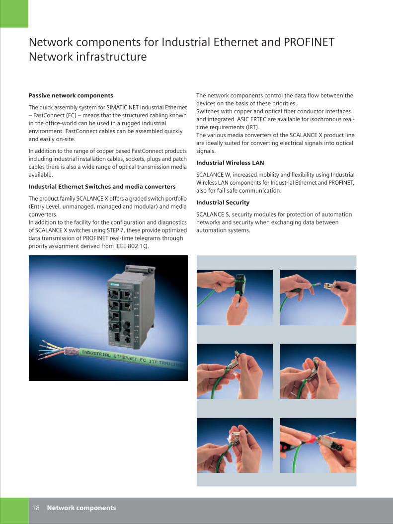
S_18_19en_neu.FH10 Thu Apr 20 09:29:34 2006 Seite 1
Probedruck
C M Y CM MY CY CMY K
��������������� ��������� ���������������������������������������� �������
�� ���������������
�� �������������������
���������� ��� � �������!�"#��$��������� ��������������%��� �$������&�$'�%���� ���������� ��������������(������������������)������������� ����������((������� �������*�������+��� �$���������� �������� ����������� ������ �� ���) ���+
����������������������(������������� ����� �$������������ �������(����� �������� �������������� ,� ���� ,����( ������������� �������� ��� ������������(���������������� � ���������*�������+
���� ��������������������� ������������������
��������������� �!$#-#�$��.������ ���(������ ��������������&���� �-�*��,������(��,����(�������������'�����������*����� +������������������������� �������������(���������������(�� �� ���!$#-#�$��.� ����� �� ��(�!����/,���� �����*���������0����������� � ��������������������)��������(�� ������(�������� �� �(���������*�������������12+�3+
������������������� �����������������������������������*�� ���������� � ������� ����������� +!����� ��������������������������������������������� ��������(�������#!�$�����$������*������������� ������� �����)�������������� �&���'+����*����� ��������*����� ��������!$#-#�$��.���������������������� � ������������*�����(���������� �(��� ������������ �(��� +
���� ������������ ����
!$#-#�$��4,������ ��������� ��������5������ �� ��(����� �����4����� �-#��������� ��������� ���������������������������,�� ����������) �������������+
���� �������������
!$#-#�$��!,� ����� ������ ���������������������������������� ����� ����� �������5���(��(����������������������� �� +
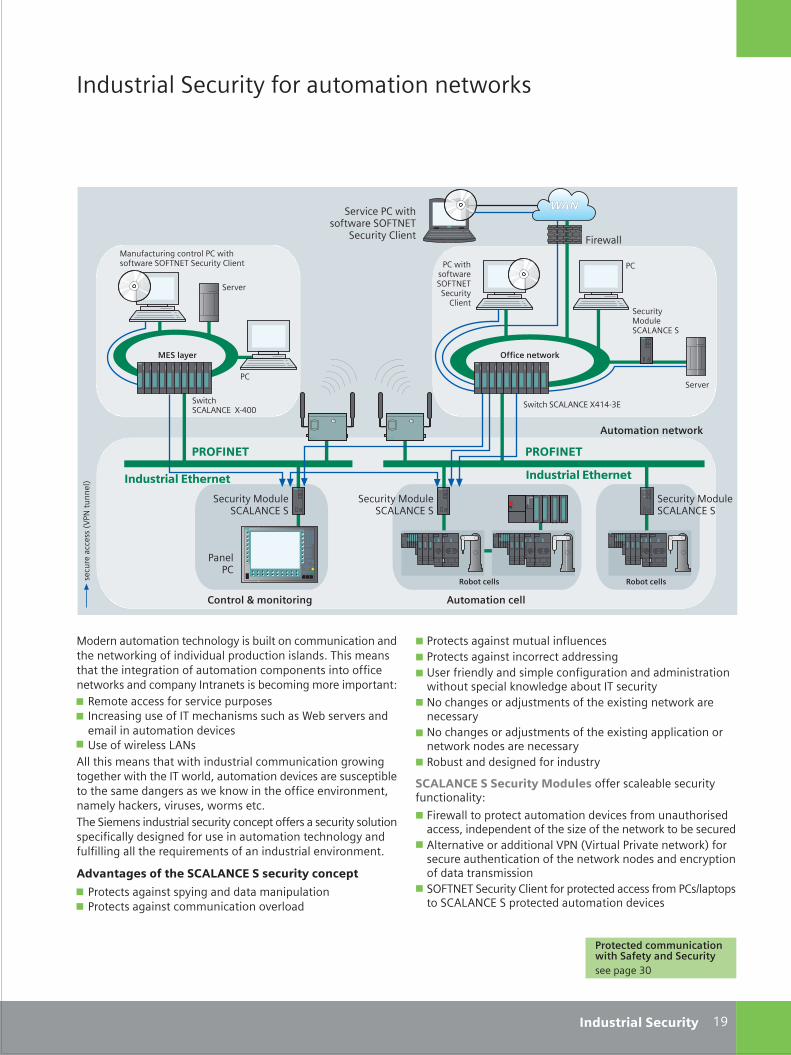
S_18_19en_neu.FH10 Thu Apr 20 10:53:01 2006 Seite 2
Probedruck
C M Y CM MY CY CMY K
���� ������!����� ����������������������
"�����������������������( �� ������������������������������������(��������*����������������� ���� +���� ���� �������������(��������������������������� ������������������ ��������� ��������� �� ������(�������������67 �������� ����� ��*�������� � 7 ����� ��(�� ������������� � ���� �4��� ��*�� ������������������������*��
7 8 ����������� �-#� #������ ���� ��������������� ����������������(�����(��(�����������������������,�������������*�� ����� � �������������� ������(�� �� ������������������������*�������,���� ������ ,�*��� � ,���� ���+����!���� ����� ������ ����� ������������ ��� ����� � ������� �������� ��� �(��������� ����������������������( �������������(������������������� ����������� ��������*�������+
��������� ������������������� ������������
7 ������ ��(��� �� � ��(���������������������7 ������ ��(��� �������������*������
7 ������ ��(��� ���������������� 7 ������ ��(��� ��������������� ��(7 8 ���������� ����� ���������(����������������� ��������������� �������������(����������� �����
7 ������(� ������9� ���� ���������5� ���(��������������� ��
7 ������(� ������9� ���� ���������5� ���(�������������������������� �������� ��
7 ���� �������� �(������������ ��
������������������� ����� ������� �������� ����� ����������� 67 �������������������������������*�� �������������� ���� ,�������������������� �0����������������������� �����
7 #��������*����������������:���&:����������*�����������'���� �������������������������������������� �������� ����������������� � ���
7 !�������!����� �$��������������������� ������$ ;������ ���!$#-#�$��!����������������������*��
�!"#���$
����������������� � �����������
� ��������������
������$
!����� �"�����!$#-#�$��!
!����� �"�����!$#-#�$��!
!��*����$����� ��������!������
!����� �$�����
!�����!$#-#�$��.<�<)=�
����������������������
!����� "�����!$#-#�$��!
�$����� �������!������!�����
$�����
!��*��
"����������(���������$����� ��������!�������!����� �$�����
��������
!��*��
�$
�$
!����!$#-#�$���.)<11
��
����� �&:��
�����
��'
�>
����������� �����������
���� �������������
!����� �"�����!$#-#�$��!
������������ ������������������������ ��� �����(��=1
���� ��������������
�!"#���$
���� ��������������
���
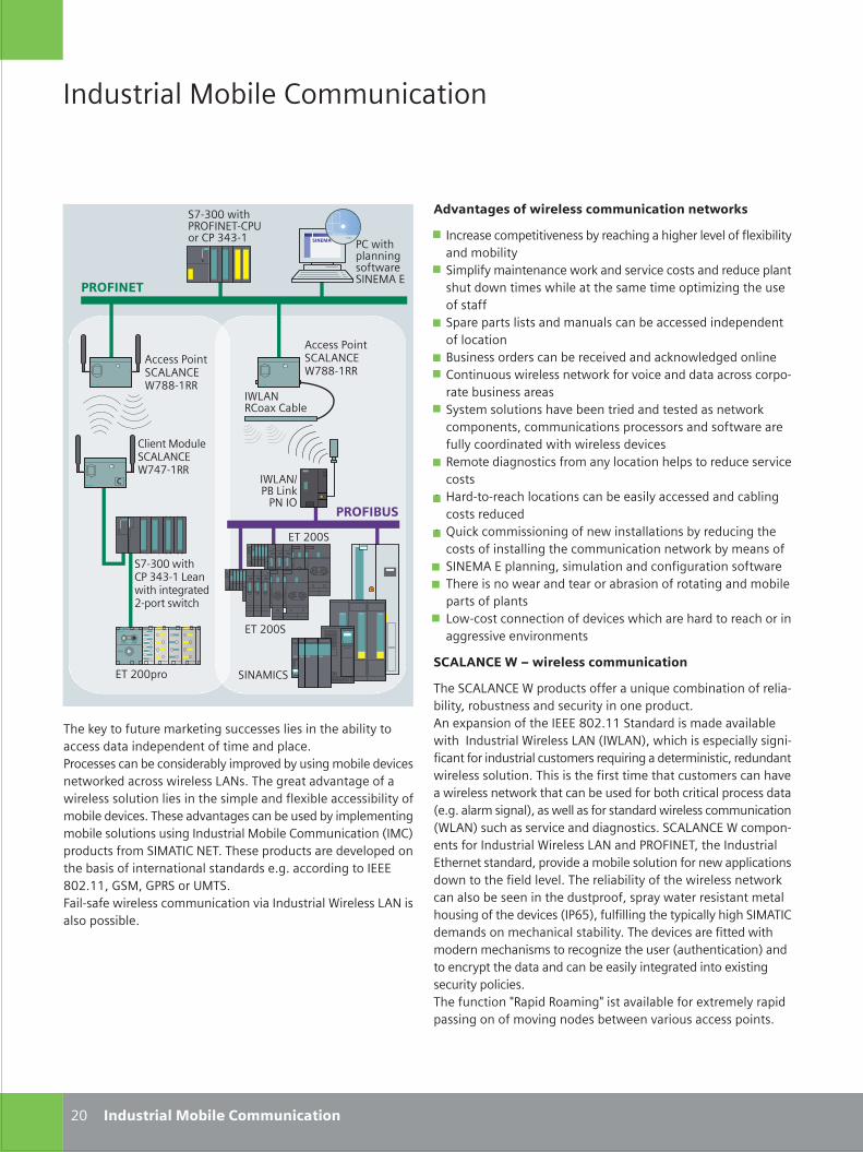
C M Y CM MY CY CMY K
����������� ��������������������� ���
� ������������ � ��������������������������������������� ��������� �
� ������������ ��������������������� �������������� ��� ��� ���������� ������ ���� ������� ������� ���
� �������� ���� ���������������������������������� ���� ��
� ����������������������������������������������� ��������������� �������������� ������������ ��������������
� ��� ����� ����������� ������� �� ������ ��������� � �������� ���������������� ������������������ ���� ����������������
� !�� ������� ������������ ������� ��������������� �
� "���� ��������� ���������������������������������� ��������
� #���������������������� ���� ������������� ���� ����� ������ ���������� ���� �������������$%&'%�������� ������ ������������� ���� ����
� (�������������� ������������� � �������������� ������ �
� )���� ����� ���������������������� ��������������������������� �
���������� ������������������
(����')'$�%*����� ���������+�������� ������������� � ���� ������������� ���������� ,'���������� ���%%%-./,00� ����������������������� ������ ����*�������)'$1�*)'$2 ���������������������������� ������� ������� ������+��������� ������� �� �������� ����������� ��,(����� ������ ��� �� ��� ���������������������� ��� �� ������������ ���� ������������ �1�,�,�����������2 ����������� ���������������������� ��1*)'$2���������������������� ���,��')'$�%*������� �������� ����*�������)'$���3!45�$%( ������� ����% ����� � ������ ��������������� �������������� ������ ������������,(����������� �� ������������ ����������������� ����� ��� ������� ������� �� �� ��������� ���������1�3672 ���������� �� ��������������&'(��������������������� ����� �,(�������������� ���� ���������������� �������� ������1�� ��� ��� ��2��� ������ ���� ����������������� ���� ���� ���� ��������� ��������,(������ ��8!����!�����8�� ������������� ������������������������������� ������������������� �,
����� ����&������������ ��
�*)'$93�)���
3$�4
(����� �� �������� ������������������ ������� � �������� ����������� � �����������,3��������������������������������������������������� ������������������)'$�,(������ ����� ���������������� �������� ������������������������������ ��������������,(��������� ����������������������� ����������� ������������� ����&������������ ��1�&�2����� ������&'(��$%(,(��������� ������������� ���������� ���� ����� ��������,�,�������� �%%%-./,00 :�& :3!��;&(�,5������������������������ ���������� ����*�������)'$������������,
/.
���� !"�
'�����3�� ��')'$�%*<--�0!!
����� &������')'$�%*<=<�0!!
'�����3�� ��')'$�%*<--�0!!
%(/..�
�<�>..�� �3!45�$%(��3;��3>=>�0
%(/..�� ��$'&���
��������#�$����������������
3��� ����������� ������$%&'%
%(/..�
�<�>..�� ��3>=>�0)����� ��� ���� ��/��� ��� ��
���� ��%
�*)'$!��������
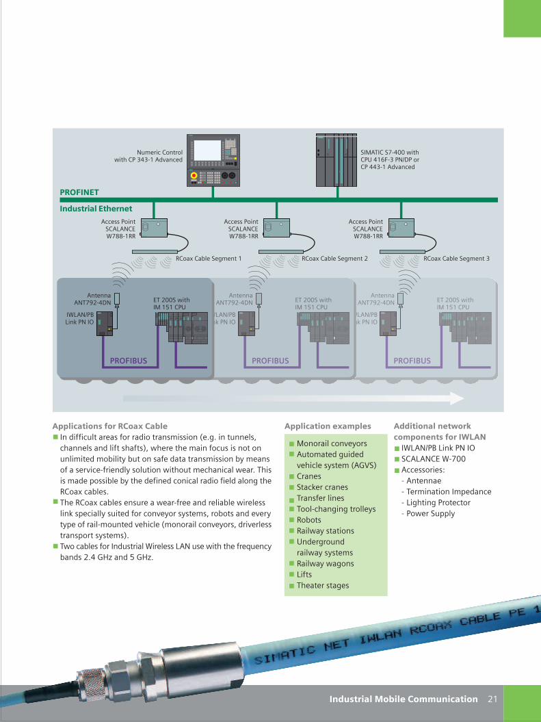
C M Y CM MY CY CMY K
'� ����'$(<?/�=@$
�*)'$93�)���3$�4
��������
%(/..��� ��&070�3;
'� ����'$(<?/�=@$
�*)'$93�)���3$�4
��������
%(/..��� ��&070�3;
'� ����'$(<?/�=@$
�*)'$93�)���3$�4
��������
%(/..��� ��&070�3;
�*)���*)��
'� ����'$(<?/�=@$
�*)'$93�)���3$�4
��������
%(/..��� ��&070�3;
'� ����'$(<?/�=@$
�*)'$93�)���3$�4
��������
%(/..��� ��&070�3;
��&'(���<�=..�� ��3;=065�>3$9@3��3==>�0'�������
!�������������� 0 !�������������� / !�������������� >
'�����3�� ��')'$�%*<--�0!!
'�����3�� ��')'$�%*<--�0!!
'�����3�� ��')'$�%*<--�0!!
/0
$�������� ���� ��3>=>�0'�������
��������#�$����������������
�&&���������������'��$������������ ����������� ����������1�,�,�� ������ �������������� ���� �2 ����� ������������� ������� ������� ��� ������� � �������������������������������������� ���� �� ��������������,(������������������ ���������������������������� ��!���������,(��!������������������������������������������������������������ ������������� ��� �� ��������� ������������ ���������1������������� ���������� ������ ��� ���2,(�������������� ����*�������)'$����� � �����+����������/,=:"����7:"�,
�&&���������'��&��
&������������'� �� ������������������ ��1':A�2������� �����������(������������(���������� ������!� �!������� � ���;������������������� ���!�����������)�� �(��� ��� ����
������������� ������&�������� ����
�*)'$93�)���3$�4��')'$�%*�<..'���������B� '� ������ (������ ������������ )��� ���3� �� �� 3���������
���� ��%
����������(�����
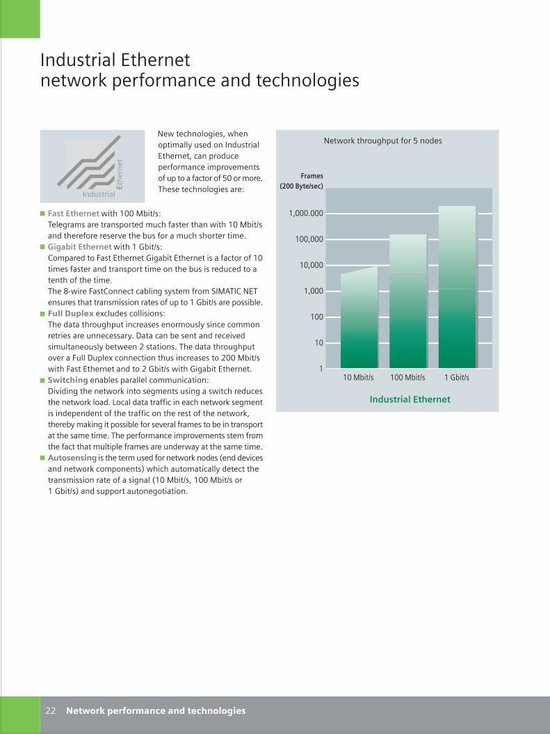
S_22_23en_neu.FH10 Wed Apr 19 11:24:42 2006 Seite 1
Probedruck
C M Y CM MY CY CMY K
������������ �������������� ��������� ��������������������������������������������� ����������������������������� ���������� �����
� ����������������� ���!"��# �������� ��������� ������������� �������������� ��!"��# ��������������� ���������"� ����������� �����������
� �� ����������������� �$"��# �%���������&� �����������$���"������������� ����������� ����� ��� ������������ ���������������"� �� ���������������������������������'(�����&� �%��������"���� � ��������)�!*��%������ ��� ���������� �� ������� �������� �$"��# ������ �"��
� �������������+���� ��� �� �������������������������� � ������ �� ��������������� ����������� �����,��������"�� ���������������� �������� ��"�������-� ����� ��������������������������&��,���+������������� ������� � ���-���!"��# �����&� �����������������-�$"��# ������$���"������������
� �� ��������"� �������������������,�����������������.����� ������ �� ������ ������������ ���������.�����/�����������������������������.� ������� ����������������������������������� �������������.������"����.�������� �"����� ����������� ���"��������� ���������� ����������������������������������� � ��������������������������������� ��������������������� ���������
� ������������� ����������� �����������.���� �0���������� ���������.�������� 1�������������������������������� �� ������������ �����0 ��!"��# �� ���!"��# �� �$"��# 1����� �������������������
���� ������������������.������������������������
��������
������
�����
����
��
�
�����.�������������������
���!"��# �$"��#
�������������������
��!"��#
--
���������������
���������������� �������� ���������
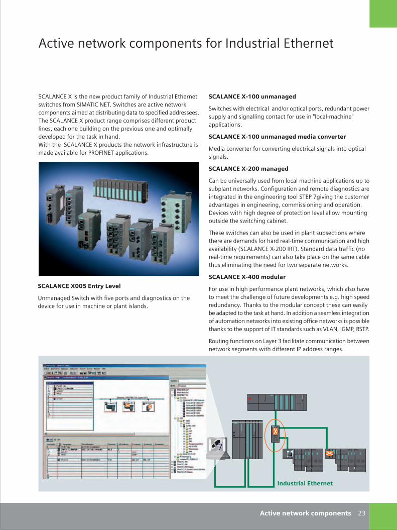
S_22_23en_neu.FH10 Wed Apr 19 11:24:42 2006 Seite 2
Probedruck
C M Y CM MY CY CMY K
)%*/*�%��2�� ���������������������������� ������������� ������ �����)�!*��%������)������ �����������������.������� ������������ ���"������������� �������������� �� �����)%*/*�%��2������������������� � �������������������� ����������"������������������� ������������������������������� .���������3���������)%*/*�%��2������� ����������.������ ���������� ����������"�����456&�������������� �
*�����������.�������� �������� �������������
���������� !!����������
)������ �������������������#����������� ���������������� ��������� ������������������� �����7��(�������7��������� �
���������� !!����������������� ��"�����
!������������������������������������ ���� ���������� ���� �
����������#!!��������
%���"�������� ���� ��������������������������� ����� �"����������. ��%�������������������������� ��� ������������������������������������)��4�8������������� ������������� ��������������������� ������������������,����� ��������������������������������������������� �������� �����������"�����
��� �� ������ ������ �"��� ����������� �" ����� ���������������������� ������������(������������������������������"�����0)%*/*�%��2(-����5�1��)���������������������0����(�������9�������� 1������ ���.������������� ������"���� ��������������������������� �������������. �
����������$!!��������
&��� �������������������������������. ��������� ������������������������������������������ ����������� ��������������������. ����������������������� �������� ��"������������������ .����������������������� ���� ���������������������������. ������+� ����������������. �� �� �"�����. ������� ����������� ������� � ����� �:/*����$!4��5)�4�
5������������� ���/�����;�����������������������"�����������.� ������ �����������������4������ ������ �
-;� ��"��������� ���������
���������!!%�����&���"��
<���������)������������������� ���������� ��� ����������������� ��������������������� ��� �
'������������������
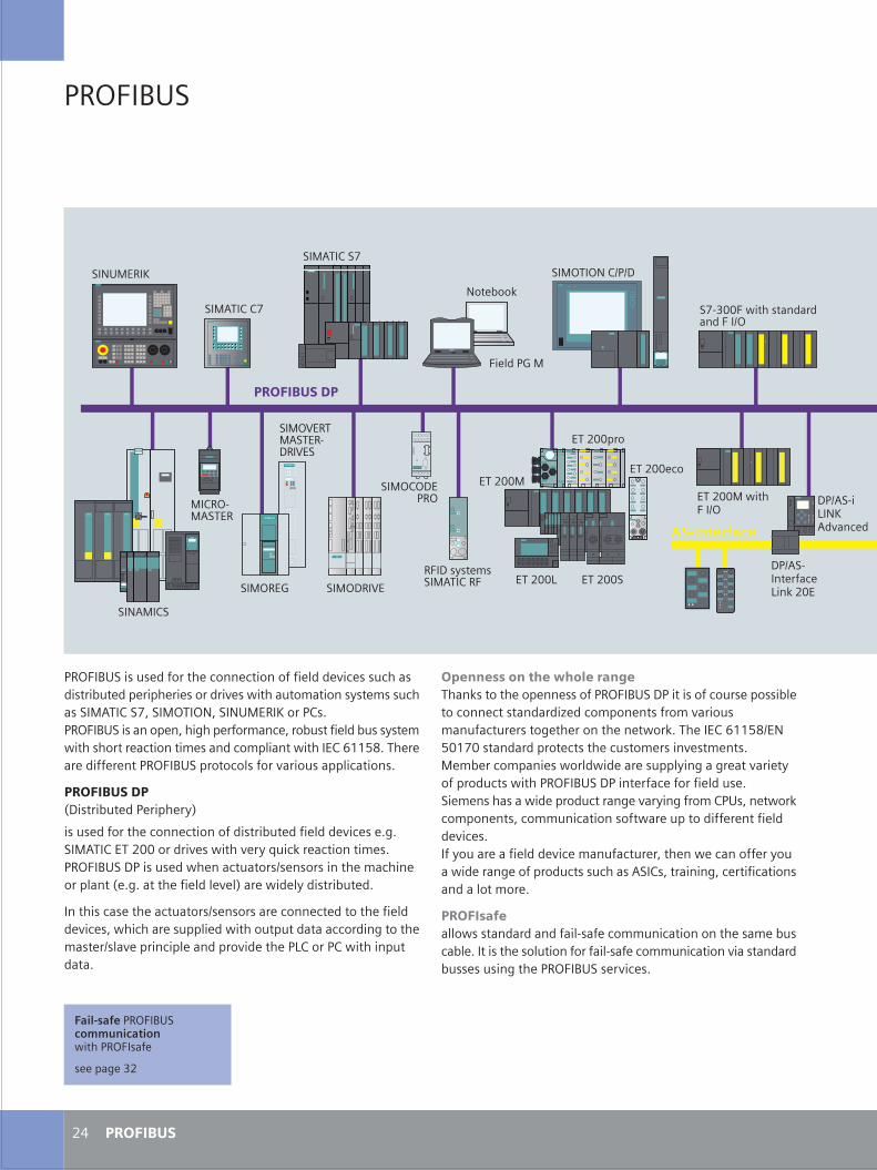
S_24_25en_neu.FH10 Wed Apr 19 11:26:50 2006 Seite 1
Probedruck
C M Y CM MY CY CMY K
�������
���� �
���� ������������������������������������������������������������������������������������������������ �������!��� �����������"#��$��%&���"��'&���' "���(�����$�)���� ������������&���*�������� ����&�������������������!��� ���������������������� ��������� ��������������$�+,,-.)������������������������ ������������������������������������)
���������/0�������������������!1
���������������������������������������������������������)*)��"#��$��������������������������!�2���3������������ ��)���� ��0������������������������4��������������� ���������������/�)*)�������������������1����������!������������)
��������������������������4�����������������������������������������&���������������������������������������������*������� �����4���������������������������������5$�����$���������������)
��� ���� ���������� ������3������������������������� ��0����������������������������������������������6����� ����������� �������� ���������������*�������������������3)�������$�+,,-.4�'-�,%����������������������������� ���������� ����)"� ������ ��������������������������!��*���*�����������!��������������������� ��0�������������������������)��� ��������������������������*�����!��*���� �$� �&�������3�� �������&��� �����������������������������������������������)���!���������������������� �����������&�������������������!������������*����������������������#��$�&��������*&������������������������� ���)
���������������������������������7������� ������������������� ����������)����������������������������7������� ���������������������������������*��������� ����������)
���������
��"#��$�$%
��"��8
��"#��$��%
������"
������5
������8�"
'������3
��0��!��� ���"#��$��
"�$�7"#����
��"9���"#����70��9��
��"$0���
��"��'�$4�40
��"0��9�
���������
������"�������4
�%7:����������������������4
�;
��'#"�$�
��' "���(
����������
0�4#�7���������5��3����
���������
��������
� ��������� ������� �� ��������������
������*��:�
0�4#�7�5�'(#�������
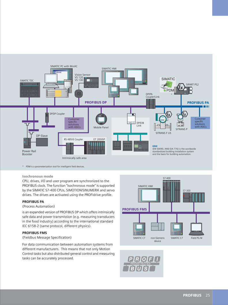
S_24_25en_neu.FH10 Thu Apr 20 10:43:55 2006 Seite 2
Probedruck
C M Y CM MY CY CMY K
������� �������$� &�������&��4�������������*�� ������!�������6������������� ������3)��������������<������������ ���<��������������!�������"#��$��%7;���$� �&���"��'4��' "���(����������������)������������������������������*���������������������)
����������/��������#��� �����1
�������=���������������������� ��0���������������������������!������������������������� �������/�)*)� �������*�������������������������������!1���������*��������������������������������$�+,-.7��/�� ����������&�������������!����1)
�����������/��������"����*���������������1
���������� ���������������������� �������!��� ����� ���������� ������������)������� �����������������!�"�����$����������3�����������������������*������������������� �������*���3������������������!����������)
0�4���5��3
��"#��$�>"���"#��$��$������?��#$
"�����������
�� /�'�-��@�&�#'�����#�%%+1��������������������������6����������*���������������!��� �������������������������*����� �����)
9������������9��,��9��,:�
0�4�#$������45��3
����#'��� �����#'���
$���� ������������������������#��$�
����������
���;.-���$������
������������!����������
��"#��$��0$
0�40��$������
���������
�����������������
0�7�����
$���� ������������������������#��$�
�-
���#������
��������
�����������
��"#��$�>"�
�%7;��
�%7:��
���7��� ���������
��"#��$�$% ������8�"��"#��$�$%
���������
A
A �0"���������� �����6����������������������*�����������������)
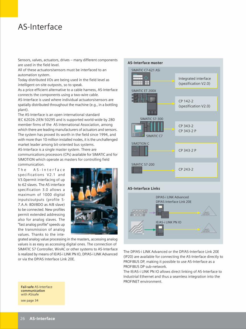
S_26_27en_neu.FH10 Thu Apr 20 10:35:28 2006 Seite 1
Probedruck
C M Y CM MY CY CMY K
����������
���� ��������������� �������������������������� �� ����������������������������������� ����������� ������� ��������������������� ���� ��� ���������� ����������������������������������������������������������������� ������� ��� ������ �� ���� ������������������������������ �������������������������� ������������ �� ��������������! �!����������������������������!������������������� ������� ���������������������������� ��� ��������������"����������� ����������#��������������������� ������������ ����������$%�&'('&�'�$)�*('+*����������� �����! ����!�������',(������������ ����������������� ������ ���� ���� ��!�������������������������������� ����� ���������� ������������������� ��������! ����������������������-++.����!����� �������-(������ ������������ ���������������������������� ���������� ������� ����������������������������������������������������������������� �������� ����� ���� ���"%/�#�������� ����0���%���� ���0����)�!����� ��������������� ��� ��� ����������� �������� ��
�����������������"���1����� ��2'�(#
��0���%�%3�&'-����
%/�-.'�'"���1����� ��2'�(#
��0���%��3�4((
%/�4.4�'%/�4.4�'�/
��0���%��3�'((
%/�'.4�'
5/������6�)7��������5/������������6�� �'($
��0���%�%3
��0���%�$��'((8
����5/������6�)7��������� ������5/������������6�� �'($"�/'(#����������� ��� ���������������������������������� /9�:�;<��5/��� �������� �������� ������������������/9�:�;<��5/��������! � ������$������6�)7�/)������ !������������ ���� ������������� ����������$��������������������������������� ����� ����/9�:�)$������� ������
����������� ����
����������������
%/�4.4�'�/
��0����)�%
'&
�$������6�)7�/)���
� � � � � � � � � � � � � ���������� ��� 2'�-� ��24�(����������������� ���� �&'������������������������������� �� 4�(� �� !�� �=����� � -(((� ������������� ������� "�� ���� ��3����>�,5��,5������;�����#� ����� ���������)�!��� ������������=������������������ � �� �� �� ������� ���?����� ���� ���?�������������� ��������� �� � �� �������� ��� �� � � ���� ������������� ��������� ���������������������������������� ���������������������������������� ���������� ������ �� ��0���%��3�% ��� ������@���%� �� �������������� ������������������1����������� ��$������6�)7�/)�����5/������6�)7�������� ���������5/������������6�� �'($�
����������
���������������������� �������!���������
��������4.
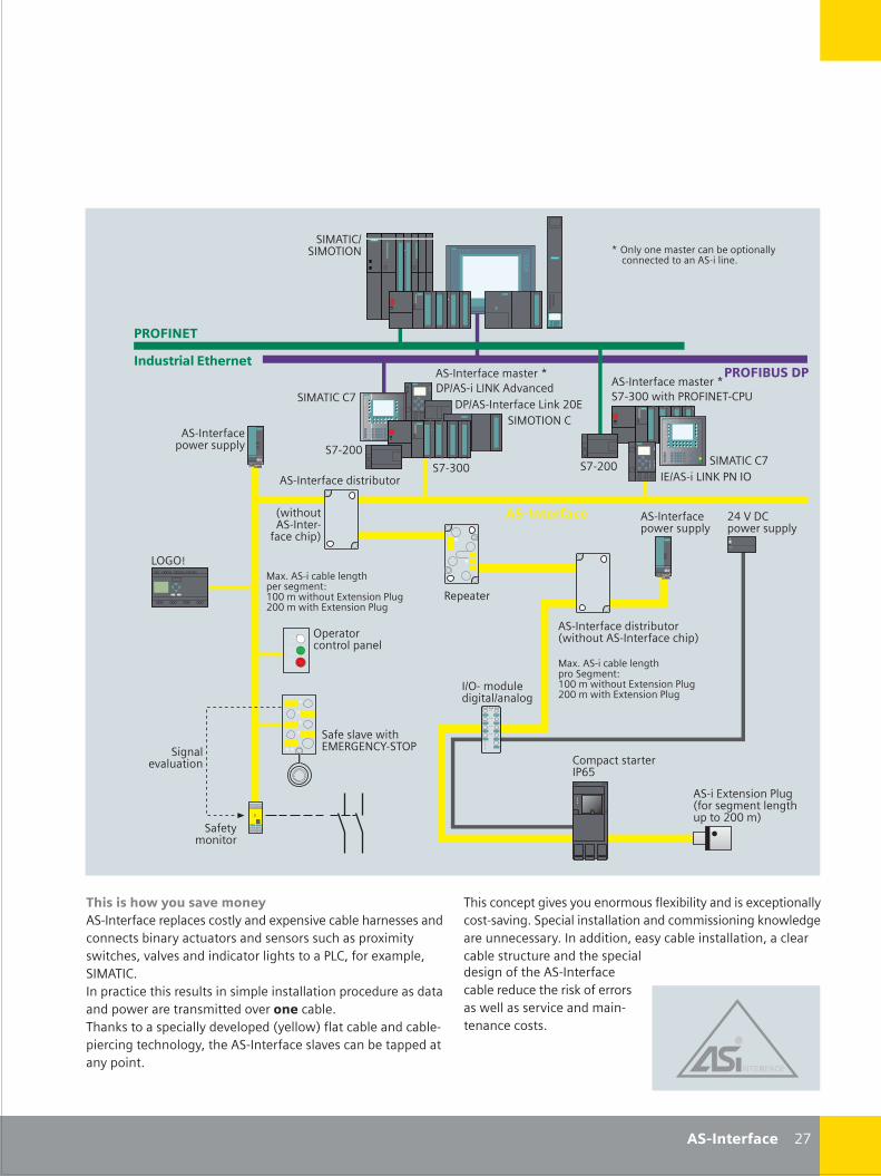
S_26_27en_neu.FH10 Thu Apr 20 10:47:40 2006 Seite 2
Probedruck
C M Y CM MY CY CMY K
�������������������� ������������������������ ���������=������������������������� ����������������� ���������� ������������ =������!����������������������� ���������� ��/6%�� ���=�������0���%������������������������������������������� ���� ��������������� !����������������� ���������������� ��� ���������������� ����"���� !#������������������������������� � ������������������������������������������ ����
������ ������������� ���� �� �����=���������������=����� ����� ������������������������� ������ ������ ����� � !���������������������������� �������������������� ������������������������������������
��0���%���0����)
�������������������� �"!��� ������������������#
����������� !���������
������ ������������� �
"!��� �����������
�������#
9������
6�A�B
����� �� ��� ������
��������!���$0$9A$)%C����/
% ������������/&*
����������� !���������
�����������������D �����������
����� ��� �
����������� �
'.�2�5%� !���������
�����$=����� ��/���" �������������������� �'((��#
0=�����������������������������>-((���!��� ���$=����� ��/���'((���!����$=����� ��/���
0=�������������������� ��������>-((���!��� ���$=����� ��/���'((���!����$=����� ��/���
'3
������� ���������������������������������� � ���� ����!����������������������������� ����
D ����� ��������������� ��� ��������� ��������� �������������
����������
��0���%�%3 5/������������6�� �'($
�3�4((
�3�'((
��0����)�%
5/������6�)7��������
�������������������� �
����� !�
����������
��"�����#�!�������
�����������������D�3�4((�!����/9�:�)$��%/<
�3�'(( ��0���%�%3�$������6�)7�/)���

S_28_29en_neu.FH10 Wed Apr 19 11:32:07 2006 Seite 1
Probedruck
C M Y CM MY CY CMY K
�����
��������
� ����������������
������������� �� �
�������������
����� !
���������������������� !
���"##
���$##
%�������� �&�' ����(#� %���������
���$##���(##
���)
���$##�����*�+������,
���(##
���"##
��������
���� ����
�������
���$##�����*�+������,
��������������� �������
���$##
(-
��������
���������
�'' ������������������-#
%���������.�/���' /
� �����������������
� ����������������0 �� �/�&& � ��01�� �� 2��� �234 2 �� /����15�4����6���������7���� 4��� �('�� ���� 5��� /��� �&�' ���/'�221��'������3��' ���������!�� 1� /7�����&�����/�� /��������1��� ���/�&'���5 �&��2�� � ������������ �7�1'�4������ 89 �����������/�������������&���� ����������&��2��/1�����4��� �� ����*�+��,���4��&��&��4���& '�221��'�����!����������.����&:�/ �;0 �5��5�����/1�����4��� �� �<1������ �&�'
9 ����������������&���� ����������&��2��������*�+��,�
9 %���������.�/���' /��/%�������� �&�' ����(#�&���� ����������&��2�*�+��,��������� �&�'
9 %���������&���� ����������&��2�*�+��,���.�=����
�� ������1'������������(##6���$##6���"##6���,��*�.����������6/����� �'���5 /0 �� ��� � ���������'�221��'������3��' ���������� 5��� /��� �&�' �7� /�����3� �3��' �� /1���5�'�����44 �0 &�� 0 ��5&�����/ /���� � ��� �����7
���������� ������������������������� !��"�������#��!
�*�+��,�� 52 ���'��0 4��� /����/1�����4��� �� �0 2 ����&/ ��' ������� 3� � ������ &1�'����6���'�44 /�*�+���3���� �7���'��0 /�� 1���5���41��������4���5�������������6���������$##�"##��,�����%����/����� �&�' 6���������������������������7���'' ��3���������������##��������������������'��0 1� /&������ 4 ��� ���������������7���2 ��������44����/��/�*�+��,��4�� �'��0 1� /�����1��� 2�/�&�'��������*�+���7
��������
��$"�����#���� �� �
���,��*�.
������������������.
����
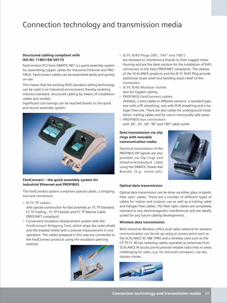
S_28_29en_neu.FH10 Thu Apr 20 10:39:10 2006 Seite 2
Probedruck
C M Y CM MY CY CMY K
���� '����� '���4�5 ��/�����2������2 /��
���"��"� $���%#��&���'�#���������������(�))*+)����,+)-.
+������� '��+�!&��2�����������>1�'���� 204 � �� 2&����� 204��5'�33 �'�04 �&����/1�����4��� �� ���/�*��+��,�7+������� '�'�04 �'��0 ��� 204 / ���4 ��/>1�'�4 ������ 7
���2 ��������� ������5*?"@����/��/'�04��5� '���4�5 '��0 1� /������/1�����4 ������2 ���� � 0 ��04��5��/1��� �����/��/6���1'�1� /'�04��50 2 ����&�����44�����'�04 ���/��'� ��7��5��&�'���'���������5�'��0 � �'� /���������� >1�'���/� '1� ��� 204 � �� 27
9 ����(��/0,��#"&��12+34�)0,3���$�)*+35�� � ������������ �& � �' ���������� ���155 /2 ��4��1���5��/�� �� �/ �4��41����&���� �����44������&*?"@'��� '�������� &� 4/��*�+���'�234����!7� �4 � ��&�� ��������3��/1'����/�� ��+�*?"@�4153����/ �//������4������� 4� &��/0 �/��5������� 4� &�&�� '��� '����7
9 ����(��/0,�6�$"#����"�# ��4��&��)�5�0��'�04��5
9 �������������(��� �����%# ���� 4/ /6(���� '�04 ���/�&& � ��� ������8�����/��/� 3 6�� ��������� �����56�� �����,*�� �����5��/����4�5 �&� �� 7� � �� �4��'�04 �&��1�/ �5��1�/�����4�4�����6����4��5'�04 ���/&��1� ����������'�44 ��& �� ��7
9 ���������%"������ ���������$#A6$@A6B#A6C#A��/D-#A'�04 �1�4 �
7���������'�������8����#�����&�������'�8�%# ��''"�����������$ �
�4 '���'�4�����2�������&�� �*�+��,�%���5��4��� �4��3����04 ��� �4�3 ���5� ��/� 4 3��� �����/��/ '�04 1���5�� ��������� �*��4����� � � 757 2�������4!7
������#�$���������'������
�3��'�4/��������2������'��0 /�� ��� ��� �54�����34����'&�0 ��3��''�04 �7� � �� ��120 ��&/�&& � ��� 3 ��&'�04 �&����/�����/�1�/���1� ��� 44�������4��5'�04 ��/��4�5 �&� '�04 �7� &�0 ��3��''�04 ��� '�234 � 4 � ����������� 4 '���2�5� ��'��� �& � �' ���/�� �/ �44 �1�� /&���� &1�1� '�04��5/ � 4�32 ���7
9�� # ���$���������'������
������/1�����4��� 4 ������4�'�4��/��� �����&����� 4 ��'�221��'�����'��0 � �131���5���'' ��3�����1'����� ����������--�D�*���/���� 4 ��'��/�1'����� ���@D@7*������/�����5'�04 ��3 ��� /����� ��� &��2����������'' ��3�����3����/ � 4��04 ��/��4�������� ��'��44 �5��5&����/��6 757&��2������4'��� ���6'���� �6���'� �'��� �7
����(��� ���:��� �;"������� '%#!��!�� '������$"�����#���� �� ����$���������
� +������� '�� �� 2'�23��� ��3 '��4'�04 �6�����33��5���4��/'��� '����8
9 ����(������%# ������3 '��4'�����1'����&��&������ 204 ��+������/��/6+�����4��56+��+4 ��04 ��/+������� ��04 ��*�+���'�234����!
9 ���� �� �����14�����/��34�' 2 ��� �� 2������ ����(��� �����������&����#6���'�����3��� �1� ���� 4/��/�� 0���/ /��� 4/�����3� '�� 2 ��1� 2 ������ �3 ������7� '�04 �3� 3�� /�������� �� '��� '� /���� +������� '�3��/1'��1���5�� ���14�����3� �'��52 ���/7
(C(��� ������� ����#�&!���$������'�������' $��
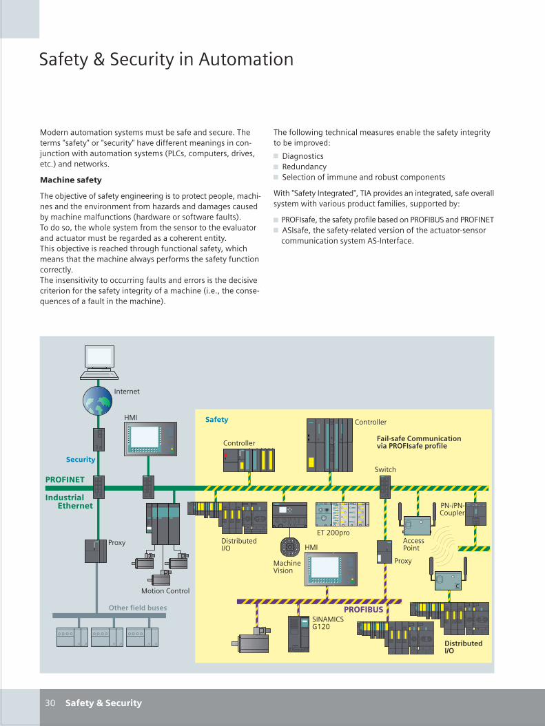
S_30_31en_neu.FH10 Thu Apr 20 10:59:56 2006 Seite 1
Probedruck
C M Y CM MY CY CMY K
���������������� �����
����������������� ���������
��
����� ��������� ���������������������� �������������������������������������������������� ����� � ���� �� �� ��� �������������� ��������� !"#�$���%����$�������$���&�� �� �����'��
�� ���������
������������������������ �� ���� ��������%������%��%(�$������ ���� ������� ���� �� ���������)������ ��������������������� ����(� ��� �� �����������������������(��&���������$��������(�������������������� ��������������(����� ����������������������������������� ��� ������������������������������������� ��� �(�������$�������� ��������������� ���(�����%�������������������� ��� �����(������� �� ���������������� ����(���� ������������������������������ ����������������� ����������������� �� ����$������ ���*� ����������(��� ��������� �&�
����������������
������((��� ����� ��(���������� ��(�������������� ���������������%�����+
, -��� �����, .�� �� �, ��(���� ������� ��� ����������%� � ��
/������������0 ���������$��0��%��������� �� ��������$�����������((�������������������%���������(���$��%%��������+
!.120����$������������%����(��������� �!.12034��� ��!.12056�, ��0����$��������������(����������� ����������������� ���
��� ����� �����������0 �������
7�0
����� �#� ���(
!��8�
������������ �
��������
7�0
#� ���((��
��������
-���������091
���� �:����
����!�� �
���� �������������������������� ����������
�����
�� ����������
0 ��� ��
6��;��%��
!5�9!5�#�%(��
�05��0#�<=;�
!��8�
#� ���((��
��������
�����
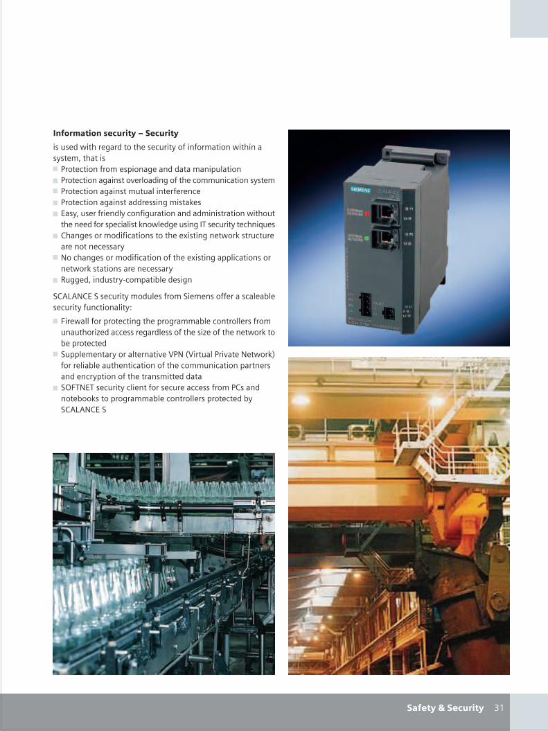
S_30_31en_neu.FH10 Wed Apr 19 11:36:32 2006 Seite 2
Probedruck
C M Y CM MY CY CMY K
�=����������������
������������������������������
������������������������������������� �������� ������ ��������$��������> !������� ��������%�� ����� ��������� �%(���� > !������� ����� �������(���� ������������ ����� �������> !������� ����� ������(�� ������� �> !������� ����� ����������� �������'��> 6���$��������� �(��� �������� �� ������ �������� �������
���� ���������%���(����' ��(������� ��0������������ �*��, #�� ����������������� ����������8���� �� �����'�������
���� ��� �������> 5���� ����������������� ���������8���� ���%%(����� ����
�����'������� ������ �������> .����$�� ��������%����(�������
�#�"�5#6�������������(������������� ������������(���(��������� ��� �(���+
> 2�����((�����%������ ������%���������(��� ���((�������� ������)��������������(�������������)��������� �����'������%�������
> �%%(��� ���������(��� ������:!5� :����(�!�������5�����'&������(���(������ ������ ����������� ����� �%��� ���� ��� ��%��� ����������� ������������
> �12�56���������(�� ���������������������!#��� � ������'�����%���������(��� ���((����%�����������#�"�5#6��
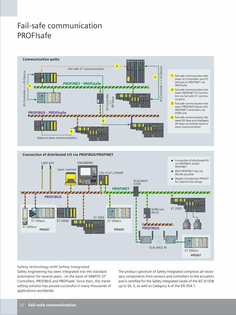
S_32_33en_neu.FH10 Wed Apr 19 11:38:17 2006 Seite 1
Probedruck
C M Y CM MY CY CMY K
������������� ���������������� ���������������������� ����������������������� ��������������������� ����������� ������������ ������������������������ ����� �!"��������� � ���#���$���������� ������� ����� ��������� �%������ �$$� ��������������� ��� ����%%�$���� �&����&��#
��� ����$�����$������� � ���
'(
��� �������$�����$����
��������������������
��������������������
������
��������)�*����+��$�
������
��������)�*����+��$�
������
�������
)�*
+�������
��������� �����$�����$����
��� ����$�����$���������&����������������� ��������+��$� ������� �,-������� � ���
��� ����$�����$���������&������� �,-���������������� �������� �������$������$����
��� ����$�����$���������&������� �!"������� ������� �,-������������ ����-.�!�/�0
��� ����$�����$���������&����+�� �����������������+�� ����������� ���� �������� �����$�����$����
���� �������!���
�����������������" �����#��$�����������#��������
�����$�������� ���������.������� �!"�����.����� �,-�
1������ �,-���� �����1/�,�%� ���
+��������%����$������23.2�����$������������� �
��������
��������
�������
-��(44%��
-��(44�$��������
-��(44%��
�-.�!�/�0�,���
��������
����%����$�� %�$�������������������������$��%� � �������$� � ����$��%����� ������ �� �� �����$��������� ���������$������ ���� �$��������������������������������/���� ���������-��25346�%������/�'��� �&����� ���������7��������-,�837�5#
���/�,�-�1
�������
-��(44%��
��"�'59 �(��,.+�/� ��� $�����
/�����
-��(44�-��(44�
���/�,�-:(46
��,"�-��;
-��(44�
�������������� ������
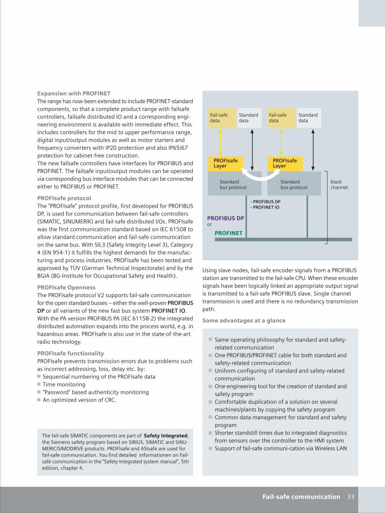
S_32_33en_neu.FH10 Thu Apr 20 09:41:34 2006 Seite 2
Probedruck
C M Y CM MY CY CMY K
������������
��� �������
������������
���������� �%����$��
���������� �%����$��
���$0$������
��� �������
��
������ ��������������
''
�������$��� �������� ����
�%!���������������������������� ���&�������9�����������$�������� �,-�� �������$��%����� �� ���������$��%�����%����$�������&������ ���$��������� ����� ����� �����������������$���� %������������������������� ����������&���������������$�#��� �$���� �$��������� ����������������%%���%��������$�������������%��.���%��������� �� �&����� ������� ������ �������<���$��$�������� �&�����(4�%����$���������� ����23.2�%����$��������$�����������$�� ���$���#������&���� ����$��������� ������������$� �������� �!"�������� �,-�#�������� �����%��.���%��������� �$�������%���������$���� %������� �������$�������� ������$������$����$��������������� �!"�������� �,-�#
����������!�����������=��� � ���=�%����$���%��������� ��������%���������� �!"�+��� �� �������$�����$��������&�������� ����$��������� >�����������,"�-��;?��������� ����� ���������.� #���� � ���&� ������� ��$�����$����� ���������� �������-��25346�������&� ��������$�����$������������� ����$�����$����������� ������ #�1�����/'�>���������������/�����'?���������7�>-,�837�5?��������� �������� �������� ���������������$����������%��$� ���� ��� #���� � ������ �������� ��������%%����������@A�>B��������$��$����� %�$������?�����������!B���>!B��� �����������$$�%������������������C�����?#
�����������!����������� � ����%����$���A(� �%%��� ����� ����$�����$�������������%��� ���������� � �D�����������&����%���������� ����������������� ����������&��� ���� � � ������������#1������������� ������ �!"�����>�-��25536�(?�������������� �������������������9%��� ���������%��$� �&�������##����E����� ����� #���� � ���� ��� ��� �������� ����������������������$������#
����������� ������������ � ����%������ ����� � �������� ��������%������ � �$�� ��$����$������� ����� ����������$#���FG ��<������������������������� � ��������G �����������G =�� &���=��� ����������$����������G ����%��E������ ���������#
������������
������������
" �� ��������� ������ ������$����� ��� ����������� �!"� �������������� ����������������� ������"#�1������� ����$���� ��� �������������$�������0�������%%��%��������%��� ��� ����� ��������������� ������� �!"�� ����#������$���������� � ��� �� ������������� ������������$������ � ��%���#
�������������� ������
��������
���������&�
G ������%������%��� �%������� ������������ ��������������$�����$����
G ������� �!"�.��� �,-��$�������������� ����������� ��������������$�����$����
G "������$���������� ������������ �������������$�����$����
G �������������������������$���������� ����������� ������%�������������������%�$���������� ���������� ��������$��� .%���� ����$�%������� ������%�����
G �������������������������� ������������ �����%�����
G �������� ���� ������� ��������������������� �$ ����� �� �� ����������$�����������������C��� � �����%%����������� ����$������$��������1���� �/�,
�������� ������������$��%����� �����%������������������ ��������������� � ������%�������� ����������"�����������������,"��-���.����+��A-�%����$� #���� � ����������� ��������� ���������� ����$�����$����#�H������������������������������� ��� ����$�����$�����������=����������������� � ����������=��3���������$��%����7#
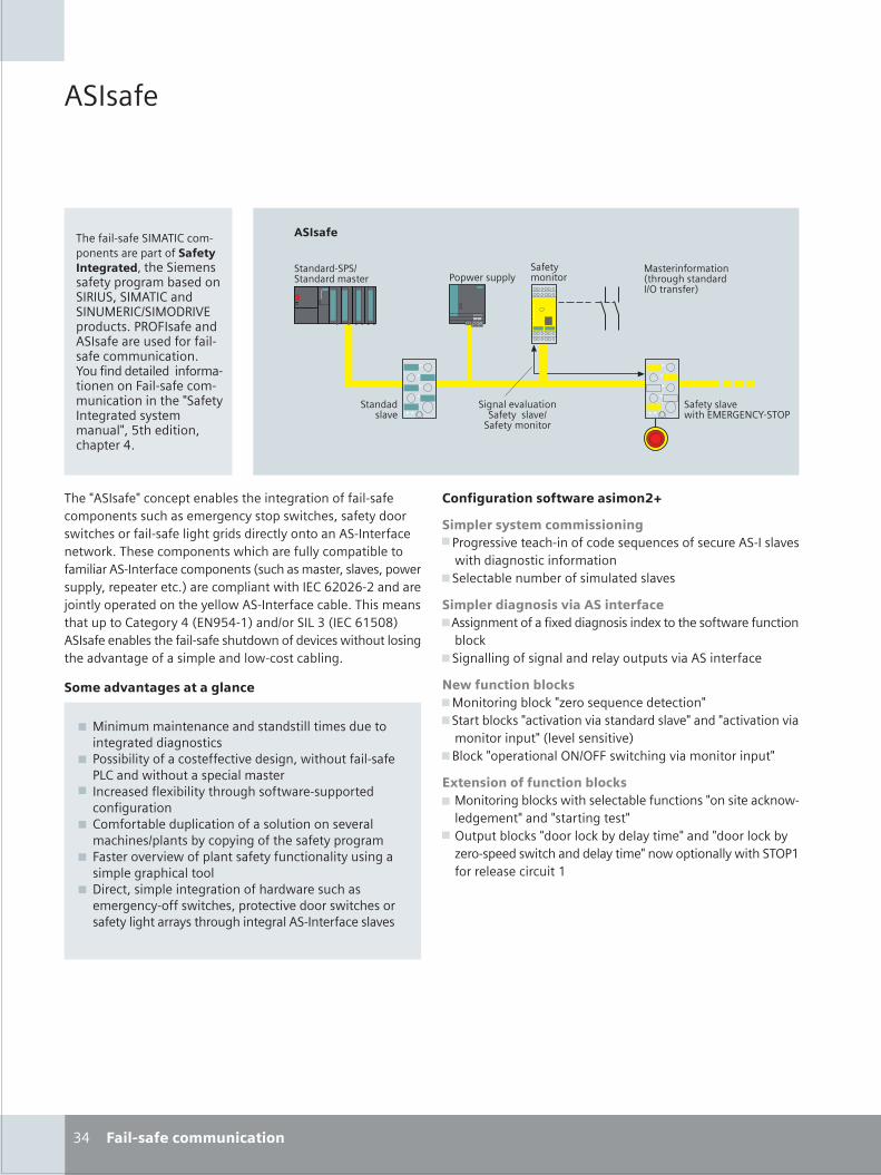
S_34_35en_neu.FH10 Thu Apr 20 09:48:38 2006 Seite 1
Probedruck
C M Y CM MY CY CMY K
�������
������ �������������� �������������������������������������������������������������������������������������� ���!"��#�����$���%&�!'������������������$���������� ��������$��������%(�$������������������� ��������'��� ������� �$������������)�������������������������$��)�*���������������+%
��� ���
���������,�-������.���( ��!&
�������� �&� ��������������
�������������
����������,�
�������,��$��������������,�
�������������
�����������������/���$���������� !��������0
&��-���$����
1+ ����� �����������������
��)�������)��������������������������������� ���������������$�����������������-�����������������-����������� ����������������������������� ������������-��2%��������������-������$������������������������� �������������������/�$�������������,�����-���$����������������%0������������-�����34543 4������6�����������������������-�� ��������������%�����������$�����������+/��7*+ 80��� ����91/���38*5:0�������������������� �����$���-�����,����-���$�����������,��������������������- �����������%
������������ �������� ������
������� � ��������� �����;&��������,����� ����������<$����������$���� ����,��
-�����������������������;�����������$���������$��������,��
������������ � ����������������;���������������=���������������=��������-����$������
����2;���������������������������$��$��,�������������
������������������ ;��������������2)>�����<$�������������);���������2�)����,�����,�������������,�)���)����,�����,��
����������$�)/��,���������,�0;?���2)�����������!� !''�-������,������������$�)
!��� ��������������������� ; ��������������2�-�������������$�������)��������2��-
���������)���)������������); !$��$�����2�)�������2�����������)���)�������2��
>��� ������-���������������)��-����������-����!&8��������������$��8
������������� �����������
; �����$�������������������������������$������������������������
; &������������������������,��������-���$����� ����&9����-���$���������������
; ������������=����������$�����-��� �$�������������$������
; ������������$���������������$��������,����������� ��������������������������������
; '������,��,��-��������������$�����������$�����������������������
; "����������������������������-����$������������ ����-��������������,������-��������������������������$����������� ������������,��
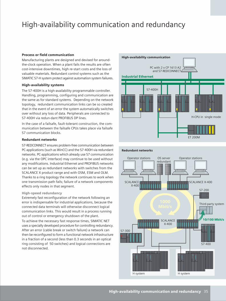
S_34_35en_neu.FH10 Wed Apr 19 11:50:21 2006 Seite 2
Probedruck
C M Y CM MY CY CMY K
A�� �,��������������$��������������$������
"�#���������������������������
&�-��5>�&9492�5����B ��"�!�����
�B +66A
A �&�������������
2*
$��� �������������������������$����$��������������������������,����������$�� �� ����3���������%C������������������$��������������� �������,���-����������� ���������������������,��$�������������%���$��������������������$�������������B A���������������������$������������������$���%
"�#�������������� � ���
���B +66A����� �,��������������������������������%A��������������������������$�����������$�������������������������������������%"���������������-��3������������$���������$�����������3�����������������������,���������������������$������������-������,��-���$��������������%&������������������������B +66A,�����$� ����&�!'�@��"&�����%
����������������������$�� ��������������$����������� �$�����������-��������������&����3�������,�����������B����$������������3�%
%���������������
�B ��"�!��������$���������� ��������$�����������-���&� ������������/�$���C����1������B +66A,�����$��������-��3�%&� ������������-���������$���B����$��������/�%�%,����!&����������1���������$�����$���-���$�����������������%���$����������������&�!'�@�����-��3���������$������$��������-��3�-���-��������������:����D����$����������-��!���������!:�%���3���������������������-��3������$����-��3-�������������������������E����$��������-��3��������������������������������������%
"�#� ���������������>�������������������$�������������-��3�����-�������������������������������$�����������������������$��������������������������-�������-������������������������$�����������3�%���-�$�����$�������������$������$����������������������$���-����������%������,����������������������������������������$���������������,������������$�������������������$������%������������/���������3���-�������$��1����-��3����������������$�����������$�����������-��3��������$��$����������������������/�������6%2����������������������������������*6�-�����1���������������������������������������%
��566�
���� ����� �#����
"�#�����������������������������������������
�B 266
�B +66
���� �����������
�B 566
A������
%���������������
&'(&''�)���(
���:����D +66
���:����D +66
!���������������!����,�����$�����
���:����D +66
!���������������
A������
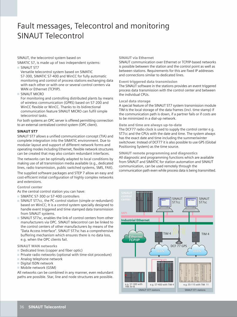
S_36_37en_neu.FH10 Fri May 19 11:26:07 2006 Seite 1
Probedruck
C M Y CM MY CY CMY K
���������������� ������������������������������� ������
���������������� ��������������������������������������������� ������������������!" ����������#������������ �����������������������������$%&&������������$'&&�����(����������������������� �������������� ������������� ����������) ���������� ������ ����������� ������������*����� ������� ������*��(������+��������,��-.�-/0
" ����������12������������������ ������������������������������������� ������ ������ ������,3-1�/�����������$4&&����(��������)��������(����0�����5������������� ������ ������ ������������������������12� ������������������� ���������50
�����������������2-����*����������������������� ���� �����������)������� �������6��� ������������,2-�� �����/0
������������������������� ����������� ������ ������ �� ����,���/���� ��������������������������������������*��������0�7����������������������������������������������� ��5������������������������� ������+������������)�������� ��5���� ���� ������ �������������������� ������������������������ �0
������� ��5� ����������������������������� ��� �������������5������������������������������*��������,�00������ �������������������������������� � �� �����������������8/0
��������������� ������ 5���������+-������� ����������� ��$���� ������������� ��������������������� �����)���� ��5�����)������0
�� ������� ������ ������� ������������������ �����*�!" ����������$%&&������$'&&� ���������" ���������� ������-�� ��������������,������������������/��������(����9�������� �������������� �����������������������*����������������������������������������������������������0
" ���������� ����������������5���� ������� ���������������������� ������*���2-�0������������ ������� ���������5��������� ������� ��������������������� ��������������������:7����� ��������� �:0����������� ������ ���������*������������ ������ �� ����������������������������00� ��������2-�� ����������0
��������������� ��" 7��� ����������, �������������������� /" -��*������������� ��5�,��������� ��������$������� �����/" ������������������� ��5" 7��������7����� ��5" ���������� ��5�,3��/������� ��5� ������ ������������������������*���������������������������0������������������������ ���������������0
%;
��������������� ���������� ������ �������*���+�������������-.�-$�������� ��5������������ ����������������������� ��������������� �������� ����������0�1�<�����������������������)����-����������� ���� ������������������� ���������0
������� ���� ��������� ����������������������� ���������������������*��������*�������������� ����������������� �������� ������� ������������� �����������*�������-�0
������������ ������� ��������������������������������������������������������������� ���������������������������,�� �0����������/������� ������ ��������������� ��������������������������� ������������������6������������$������ ��50
��������������� ��������� !"�"��������7����������� �� 5�������������������� ������� �������00��� ����������-�� ���������������������0������������ ����������)� ������������������ ���������������. ����� �� ��*��0�����������7���������������������������3-��,3�����-��������������/��������������� �0
������� �����! � �������������������������������� ������������������ ����� �� �������*��������������������������������������������������������������� ������ ������� ����������������������������� ������ ������������*��� �������� ������������������������0
�������������� �
#$�
�����������������
�00���$%&&� �������%#$�+
�00���$'&&� ��������' �00��=$>>=� ���������>>
7������3-�
���������>�������
���
���������
���������
�������� �����
�����������
��� �� �������� ���
� �� �
����' ����'
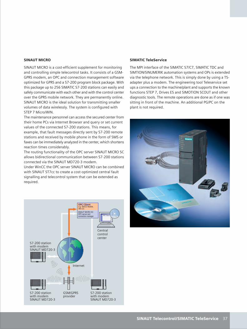
S_36_37en_neu.FH10 Fri May 19 11:26:07 2006 Seite 2
Probedruck
C M Y CM MY CY CMY K
%�
�������#�%&
����������12����� ��$���� �������������������������������� �������������������� ���������50���� ����������3��$3-1������������2-������ ���� ������������������ ���������6�������3-1����������$4&&����������� 5��� 5��0�(��������� 5���������4=;�����������$4&&�������� ������������������ ������ ���� ������ ������������ �������� ������� ������*�������3-1������������ ��50����������������������������0����������12������������������������������������������*�������������� �������0������������ ��������� �����+-����� ��.(��0������������� ����������� ���� ������� ����� ���������������������-��*������������?�� �������<����������� ������*������������ ���� ������$4&&�������0���������������)��������������������������� �������������$4&&�������������������� ��*������������������������������������������)�� �����������������������6���������� ������� �� ����������� ���������� ����������0�������������� �����������������2-����*�������������12������� ������� ������� ������ ��������� ������$4&&������� ���� ����*���������������7�4&$%������0������(���������2-����*�������������12� ������ ������� �������������� ���� �������� ��$������6��� ���������������������������� ����������������� �������)����������<�����0
�������������� �'��#���������� ����
��#���������� ����
�����-��������� �������������������.�������������7����������2�.�����+1�@���������������������2-����)������*�������������������� ��50�����������������������������$�������������������0��������������������������*� ��������� ���� �������������� ����.���������������������5�� ���� �������+-����7��*��+���������2��2����2������������������� �����0���������������������������������������� ������������������������� ����0���������������-3.-����������������������<�����0
������� ������ �����
3��.3-1����*����
��$4&&������� �����������������7�4&$%
��$4&&������� �����������������7�4&$%
��$4&&������� �����������������7�4&$%
��������
���������������� ������
���������������������������������������� ������
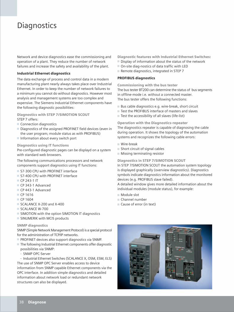
S_38_39en_neu.FH10 Thu Apr 20 09:53:20 2006 Seite 1
Probedruck
C M Y CM MY CY CMY K
��
��������
� ���������� ��� ���������� � �� ������������������ ������������������� ��� ��� �� ����� ������ ���������� ��������� � �� ��� ���������������������� ������
����������� ����������������
�� ����� ������ �������� ������������������������ ��������������������� ������������� ����� ��� ���������� � �� �������� ����� ��� ����� ������ ����������� �����������������������������������������!�� � �������������������� � ��� ���� ��������� ����� �� ��� ���� �"� � ����������� � �� ������� ����� � ���������������������������� #
�������������� ����������������������"� $�%���� �#& '��� �������������& ������������� ����� ��$()*�� ���� ���� ��� �+ � ����� �� ���������,������ ����������$()*�-."/
& ���������������� � �����������
�����������������������������$� 0�������� �������������� ������ ��������������� ������������� ������ ��
�� ���������������������������� �������� ���������� ��������������������������������#
& "%0�11�'$.�����$()*�� ���� ���� & "%0211�'$.�����$()*�� ���� ���� & '$�32�04���& '$��2�04�5����� �& '$�22�04�5����� �& '$�4646& '$�4612& "'575�' �80311�����80211& "'575�' �90%11& "�:)��)������� �������"�:)��)�������������"��.: (�;�����:'�"�������
���������������"�:$�+"���� �� �����:���� � ��$������/������ ����������������� �����������������'$<�$�� �����& $()*�� ��� ��� ������������������������"�:$�& �� �������������������� � �� ������� ����� ������������������ �����"�:$#0 "�:$�)$'0" �� �0 ��������� � �� �"���� �+"'575�' �8=�)":=� ":=� 7"/
�� �� ����"�:$�)$'�" �� �� ���� ���� ���� ��� ����������������"�:$������� � � �� ������� ������� )$'��� ���� ����������������� ��������������� ��� ������������������ �������������� �������� ��������� ���������� ������� ��
��������������������� ������������ ����������� ���& ��������������������������� �������� �� ����& )�0� �����0�����������������������7 �& ( �� ���������=��� ��� �����"� $�%
� �!�"�������������
��##������������� �� ��$����������� ���� ��-�311������ ���� �� ����������� �� ���������� 0��� ��� �������������� � ���� ���� ���� ����� ��� ������������������#
& -������ ���������� ������� 0�� ��=�����������& � �� �$()*�-."��� ���� ������ ��������� & � �� ���� ����������������� �+��� 0��/
�%���������� �� ������������&��%������ ����������� � � ���������� ��������������� ����� ��������� �������������� ������������� ���������� ������� �����> �� ��������������� � ����#
& 9�� 0�� ��& "������������������������ & :����� ���������� ���
��������������������������������������"� $�%<"�:)��)��"').��� ����������� ����������������� ��������������+�� ��� ����������/���������������������� ��������������������������� ������� �� ��� �+ ����$()*�-."���� ����� �/�5�� ��� ������������ ���� �� ��� ������������������� ���������������� �+����� ���/=����� ����� #
& :���� ���& '���� ������ �& '�� ���� �����+��� �/
�������
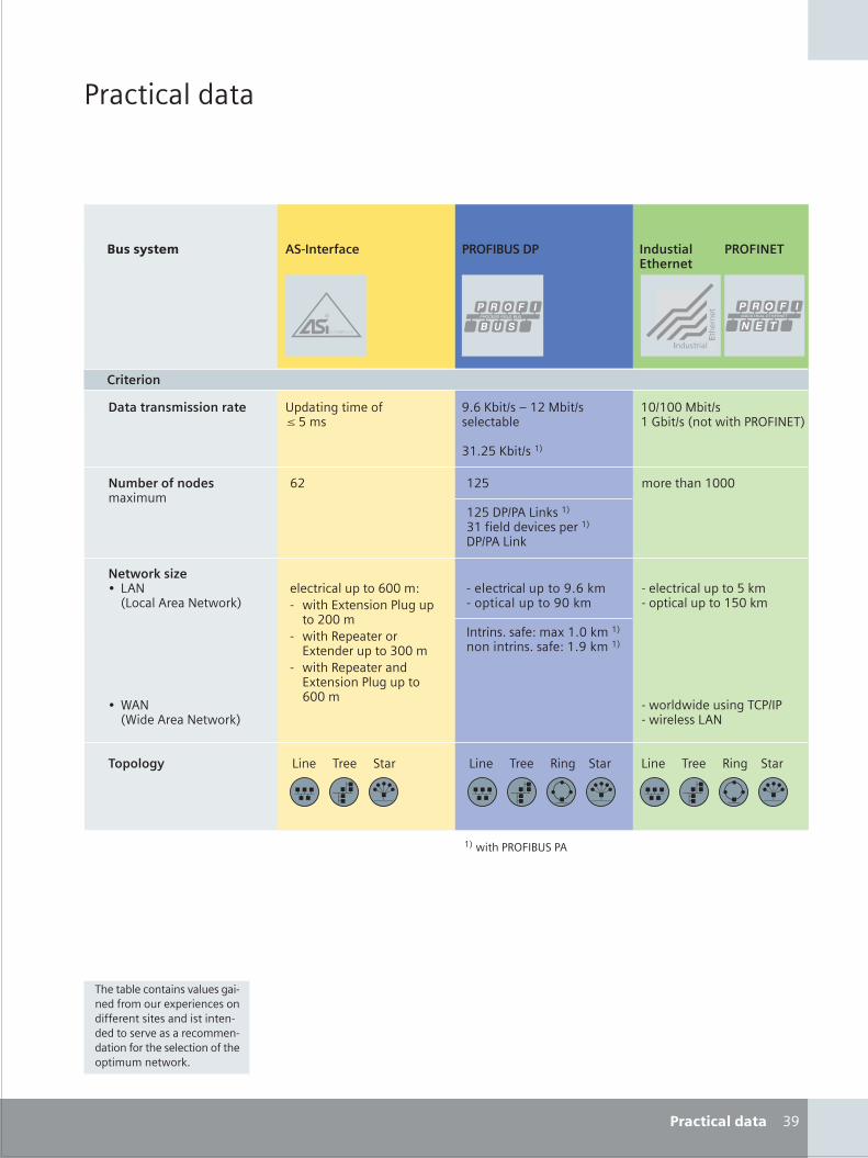
S_38_39en_neu.FH10 Wed Apr 19 12:00:24 2006 Seite 2
Probedruck
C M Y CM MY CY CMY K
$�����������
���������
������7�� ������� �����"��������
0� � ������������?���0�������������4?1���
0��������� �������'$<�$0���� � �75�
��������������������� @�6�;��<�A�43�:��< � ����
�4�3?�;��<�4/
41<411�:��<4�B��<�+�������$()*�� �/
63����������������������
43?
43?��$<$5�7����4/�4��� ���� ��� �� ��4/�$<$5�7���
��� �����4111
� ������������611��#0 ���� � �����$��������311��
0 ����( � � ���� � �� ��������11��
0 ����( � � ����� � �����$��������611��
������������& 75�+7�����5� ��� ����/
& 95�+9�� �5� ��� ����/
0� � ������������@�6���0�������������@1���
��������� #�����4�1����4/������������� #�4�@����4/
4/�����$()*�-."�$5
�7�� ������� �����(�������"��
�@
�7�� ������� �����(�������"��
.��������� �������?��
���������
�� ���� ������������ ����0� ����������� �� �� �� ������� � ��� ��������� �0� ���� �� ������ ���� �0����������� � � ��������� �������� �����
"����'���# ������������ � !"�#$�� � ��������%�&�����
� !"��%�
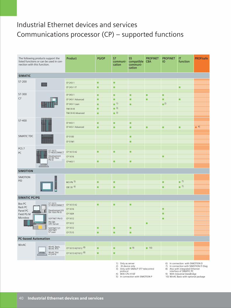
S_40_41en_neu_2.FH10 Thu Apr 20 14:02:12 2006 Seite 1
Probedruck
C M Y CM MY CY CMY K
��
�������� ������� ������ ��� ������������������ ������� ���� � �������� ��������
����������� �������������������������
����� ������ ������
��������������� ������
���������������
�������
��������� !
����������
���������
������� � �
�!"���
�!"#��
�!
�� $�#"% ��
�� ��#"%
�� &%��
�� ��#"% ��������
�� #�#"%
�� #�#"% ��������
�� #�#"% '���
�� &%�%
��
�� %(%# �$
�� %(%(
�� ��#"%
��� !
��
�� $�#"%�!"$��
��� #)"��
��� #)"�� ��������
#�
#�
%� *��+ �� ����$� �* ����� ���+#� *��+ ,�� ��-�.� ��! ���������� ������� �� /�� ��. �%(0&� �� ��������� ,�� ���*��*- �
(� �� ��������� ,�� ���*��*- !� �� ��������� ,�� ���*��*- ��" �12� ���� ,�� ���1���� �������
������� �� ������� ��3� /�� �������� ���4�1�%�� /��� 4��� ,�� ������� ���5�1�
���"�- &� !�
�4� #� (�
�� %(%# �$
�� %(%$
�� !&%&
�� %(%(
�� %(��
3� %���� %(%# �$6%(%$
�� %(%# �$6%(%$
2�
2�
���*��*-�6
4�7 ��8��5 ������� ��0��� �9 ����:�7
/���/��� 4���;/��� 8�<
/��� �����%$6�%(
!�
���������� =� ="%(77 �- �*
�*0�-�� �- �*
��� �����,�1 ������� ������ �������� �������� � ��� :� ���� � ���"������ ,�� ��� �������>
$�%�
�������������
�����������������
��������
�!"%(%#�!"8� �*--���
�!"%(%#�!"8� �*--���
����������=� ="%(77�- �*
�� %(%$
�*0�-�� �!6�*0�-���! '���
�- �4�*��"���� �� %(%$
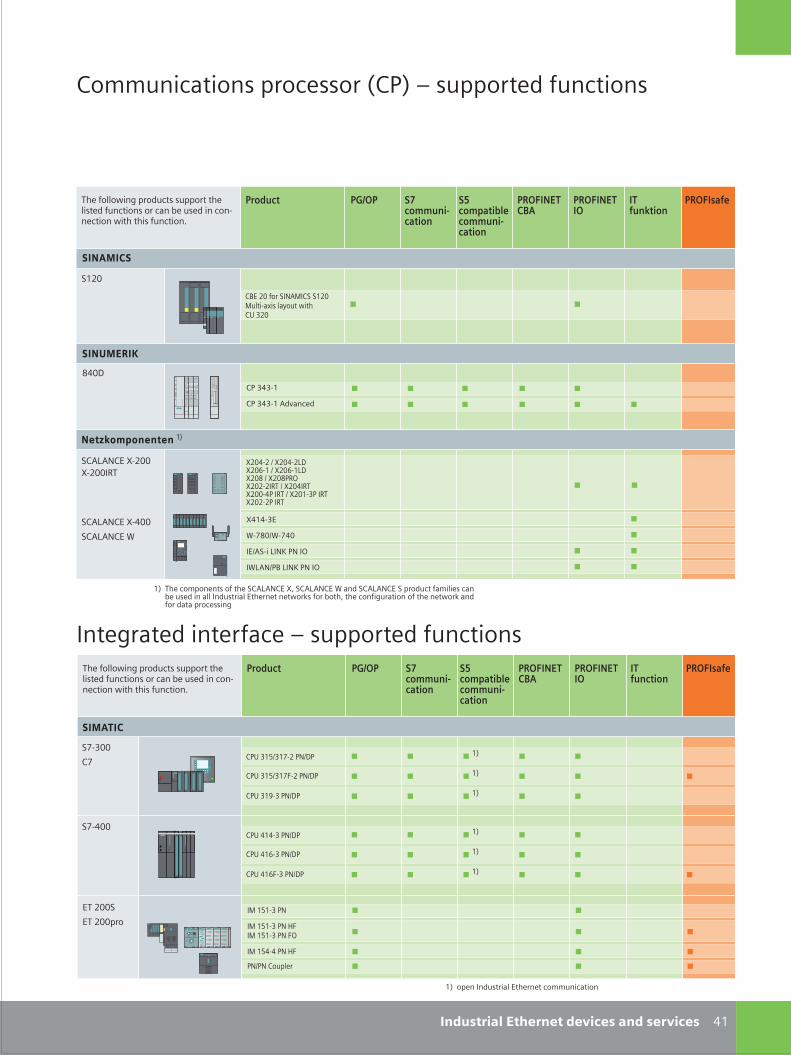
S_40_41en_neu_2.FH10 Wed Apr 19 12:02:52 2006 Seite 2
Probedruck
C M Y CM MY CY CMY K
�#����������� �������������������������
��������� ������� � �������� ��������
����� ������ ������
��������������� ������
��������������� ��������� !
����������
����"����
������ �!
�! � �#
�! � �# ��������
0���
��������
�#"�
�2� "� �� ��,����� �#"�������5� ��*��� +���- "�
��;;�������� ������� >�!& � �������� ��������
����� ������ ������
��������������� ������
��������������� ��������� !
����������
���������
�� #$#� !, ?/�� #$#� !, /)
�� #$��� !, ?/
�� #$#� !,�� "���
�� "����
!,4!, ������
#& ��� ��;������� �� ��� ���%�,�� :9 ���%�,�� . ��� ���%�,�� � ������ ��;��� ���8� ���� � ��� �������� ������� ���+�3� �� 8���9 ��� ���������� �� ��� ���+�3 ����� ���� ��������
���"#��$�������
:"���" 4 :"���"%�:"�'�# 4 :"�'�#%�:"�0 4 :"�0!6):"�"�"�6� 4 :"���6�:"����! �6� 4 :"�#� ! �6�:"�"�"! �6�
#&
���%�,�� :�"��:�"���6�
���%�,�� :����
���%�,�� .
��� �����+�� ������� ������ �������� �������� � ��� 8� ���� � ���������� +�� ��� �������=
��� �����+�� ������� ������ �������� �������� � ��� 8� ���� � ���������� +�� ��� �������=
�!- #$4 #�/�" !,4�!
#&
�!- #1� !,4�!
#&
#&
�!- #$4 #��" !,4�!��� ��
��
������
�!- �#'� !,4�!
#&
�!- �#'/� !,4�!
#&
#&
�!- �#�� !,4�!
:�#�� �
.��0�4.����
��4��� %�,< !, �)
�.%�,4!2 %�,< !, �)
�������
#& ���� �������� ������� ��;;�������
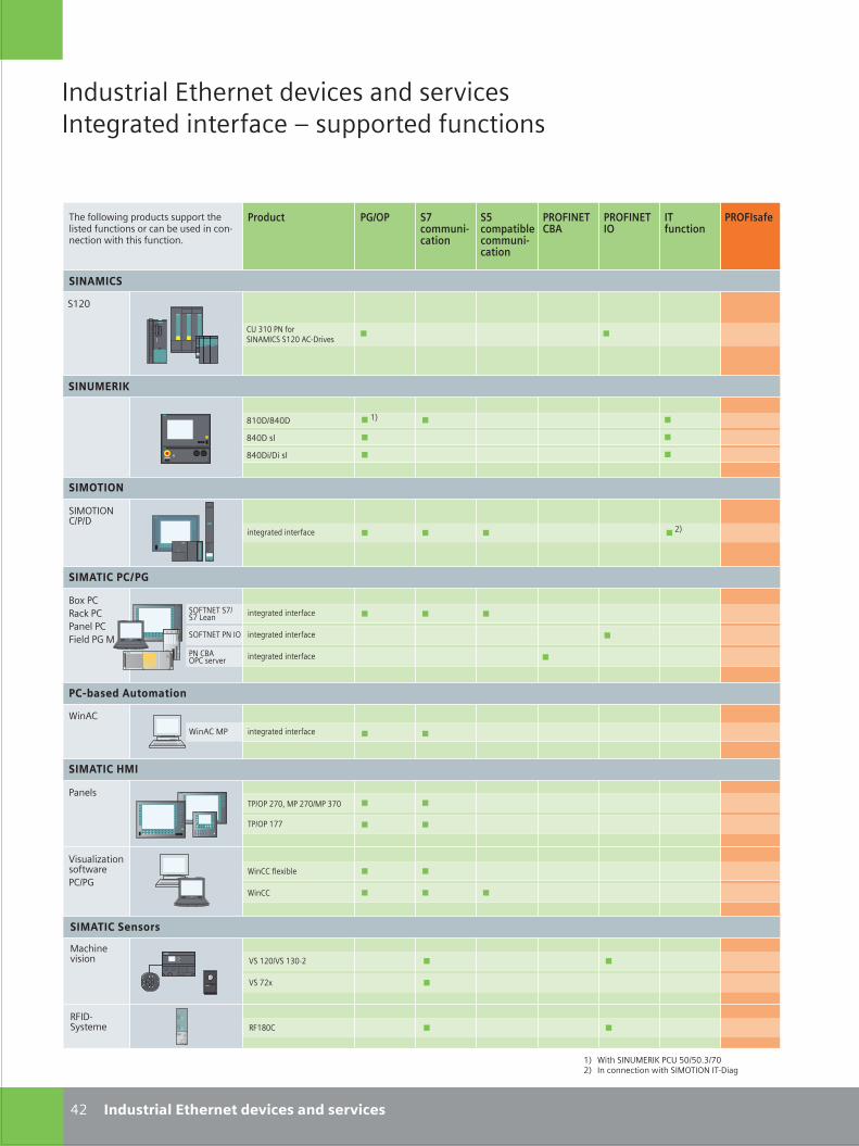
S_42_43en_neu.FH10 Wed Apr 19 12:04:39 2006 Seite 1
Probedruck
C M Y CM MY CY CMY K
��
�������� ������� ������ ��� ��������������� ������� � �������� ��������
�� ��� �������� !"� #$%#$&'%($�� �� ��������� )�� ���*+�*� �+,-��
�������� �������
���������� ���� �
�����������
�������� �������
���������
+!%*! �($. �! �($%�! '($
+!%*! �((
�������� �������
��������
���*+�*�"%!%-
/�0 !"���1 !"!���� !"2��� !3 �
��4"
!�����
��4" �!
��
����� ������ ������
��������������� ������
��������������� ��������� !
����������
���������
5����6��������)��!"%!3
��"" ���07��
��""
���������� ��
���������� 5� ��$%5� �'$,�
5� (�0
�2�-,�8���9� �2�:$"
������������������������������������
+�� �����)�� ������� ������ �������� �������� � ��� 7� ���� � ���,������ )�� ��� �������&
���$
"� '�$ !� �����4��"� ���$ 4",-���
�������
��� ��!�"
:�$-%:�$-
:�$- ��
:�$-%- ��
��
�*2+��+ �(%�( ;���
�������� ��������*2+��+ !� �*
�������� �������!� "/4*!" ����
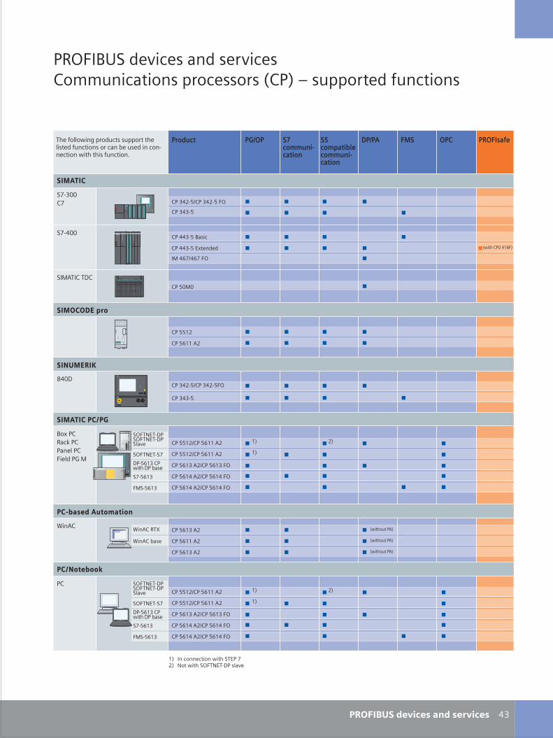
S_42_43en_neu.FH10 Thu Apr 20 10:28:03 2006 Seite 2
Probedruck
C M Y CM MY CY CMY K
�'
!�*2�/�� ������ ��� ������"�99�������� �������� <"!� � �������� ��������
����� ������ ������
"���! �#���������������� ������
��� ���������������
"! ##��%"! #=�� 4�
"! ##��%"! #=�� 4�
"! #=�' 4�%"! #=�' 2*
"! #=�� 4�%"! #=�� 2*
"! #=�� 4�%"! #=�� 2*
"! #=�' 4�
"! #=�� 4�
"! #=�' 4�
���������� ���� �
���� ��� #
������
/�0 !"���1 !"!���� !"2��� !3 �
��4"
!"
�*2+��+,-!�*2+��+,-!�����
-!,#=�' "!)�� -! 7���
��4" �+>
��4" 7���
�����������
�(,'$$"(
�(,�$$
"! #$�$
���4+�" +-"
��� ��!�"
"! '��,#%"! '��,#2*
"! '�',#
�� �=(%�=( 2*
"! ��',# �0������
"! ��',# /���
"! '��,#%"! '��,# 2*
"! '�',#
:�$-
������$�%�
"! ##��
"! #=�� 4�
�!�&�' �������������������
<)�� "!� ��=2�
<)����� !4�
<)����� !4�
<)����� !4�
+�� �����)�� ������� ������ �������� �������� � ��� 7� ���� � ���,������ )�� ��� �������&
��
��
�� �� ��������� )�� �+�! (�� ��� )�� �*2+��+,-! �����
�*2+��+,�(
��
�(,#=�'
2��,#=�'
"! ##��%"! #=�� 4�
"! ##��%"! #=�� 4�
"! #=�' 4�%"! #=�' 2*
"! #=�� 4�%"! #=�� 2*
"! #=�� 4�%"! #=�� 2*
�*2+��+,-!�*2+��+,-!�����
-!,#=�' "!)�� -! 7���
��
���*2+��+,�(
��
�(,#=�'
2��,#=�'
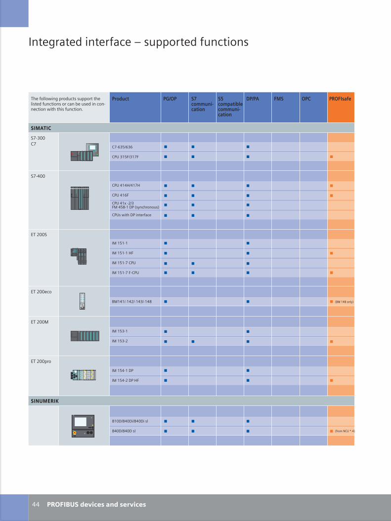
S_44_45en_neu.FH10 Thu Apr 20 10:24:17 2006 Seite 1
Probedruck
C M Y CM MY CY CMY K
����� ������ ������
����� ������������������ ������
��� ���������������
�������
����������� �����������������������
������������������� ��
!"�##$
% ������
% �������&�
�'�(��(�(
����������'�
�������&��'&
������(�
% �����'����
% �����'������
% ������
% �����
% ���������
% ���������&�
��
$'��##
!"�##
!"�##)��
* ��������������
!"�##���
�������
��#���#����#����+
��#���#���+
%���,� ��-������� ���.���))����-����������
$'��##�'
�* �������+��
� ��������������������������
����/�0���12��
"�����++����,�)��-�������))�������+����-��������������� ��3�����-����������������������������������2
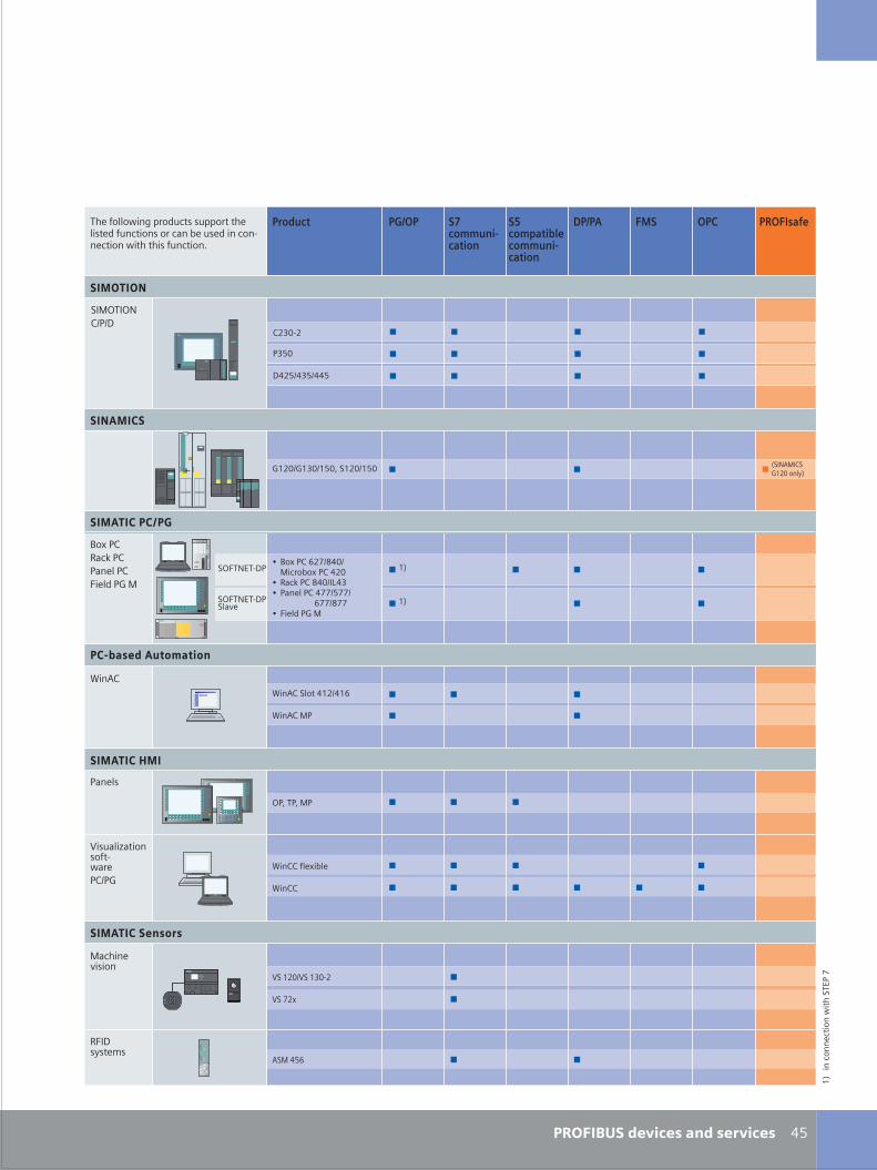
S_44_45en_neu.FH10 Wed Apr 19 12:06:52 2006 Seite 2
Probedruck
C M Y CM MY CY CMY K
����� ������ ������
����� ������������������ ������
��� ���������������
��� �� �
��
+�����4�����
5���#5����#�
5��&�
6�#6��#��#7���#��#
�������������
8 )������'&��# ����3�������#
8 9+�:������#$;��8 �+�� �����&&�&&�������������������'&&�&&8 ��� ,��6�
������������ !��� �
<��=��� �������'
<��=�� �
��������"��
>�7�"�7� �
5���+ �?+������-��2+�����6
<�����- ���3 �
<����
)�����9+�:����+�� ������ ,��6�
<��=�
�+�� �
�>�"/!"���� +4�
������������ ��
��������
��#�
���#
���������
�$ >"$>/���
9�$��������
=� ���'
� ��������������������������
��$/= $��6�#��� ��
"���-� �2��*�(��,�������((������� ����,�-�������������+��3�����,����������������2���������-�������1
��
����
����
����
����
2���
��"!
��&
�>�"/!"���
��
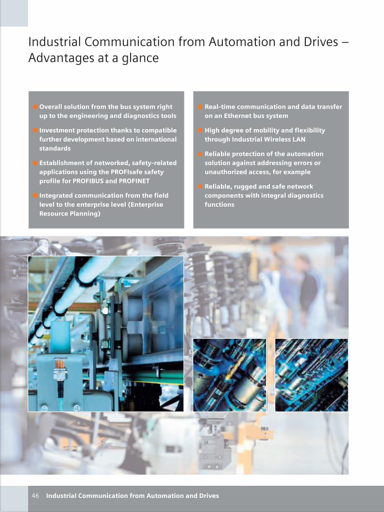
S_46_47en_neu.FH10 Wed Apr 19 12:09:59 2006 Seite 1
Probedruck
C M Y CM MY CY CMY K
��
�������� ����������� ��� ��������� ��� ���� ����������� �� � ������
������������ ��������������������������������� �� ���� ��� ������ ���������
� ������ ��������� ���� ����������������������������� �������� �� ��� ��� ����� �����
����������� ���� �������������������������������� ���� ������������������������������������� !"�� �������#�$
� ������������ ����� ��������������������������� ���������������%� ������������������ � �&
������������� ����� �� ���������� ���� �� ������ ������������
'���������������������� �����(�������������� ��������)��������*+#
���������������� ������������� ���� ����� ����������� ��������� �����,���������������(�����
����������������� ������� �������� � ��������� ����������� ������ ��� �
� ��������-�� ����� �����+����� �� ��.�����
S_46_47en_neu.FH10 Thu Apr 20 14:07:56 2006 Seite 2
Probedruck
C M Y CM MY CY CMY K
������ ������������ �������
//01�1�22���1�34�55�62
!��
"���
���#��$
%�����
��% �������$
�����$
�����
&���#'���
!�(
&'� #�)������ '�� #����� $�� *�' �� �����* �� ����������� ���'��� ��� ���*�+� ���� � &�����$ ������������������, -��'��� ��� �������� �� �����)�� �� #���� ��� ������� �������� �� �#���� ������� ���'������� ���������������,%����� ��� �'� ��( ��� ��� $�� *�� ����� �'� ������������ $�� �.���� *�'� � ��* ��$�,/� �'��+ $�� �� $�� ������ ��� �� ���+�� ��*�� �� ������ $�� ��(0
��������� �������(��7
!�( ���
������
&�����$ ��������� ���������
���#����� -���� ���������
��1�&�� %�� 2 %����� ������ �$����
"��*�+ �������� *�' �������� 3�'����
%45!�"3&
�������� 3�'���� ����������� � ���6�"�3 7
�������� 3�'���� !����������
�������� 1�)�� ����������� � ���6�"�3 /
�������� �����$ � ���6�"�3 �
"��*�+ �������� *�' %45!�-8�
��9��������
��1�&�� ��������
��1�&�� �29:��
��1�&�� &��'�����$
��1�&�� �����$ ���������
��1�&�� 3& :��
6��� ������ 65�50
��1�&�� %�
��1�&�� ������� ����*��
��1�&�� �&
��1�&�� %�����
��1�&�� /��� ���()��
��15&�5"
��"�1���
��"8134�;
<��)��9�#��� ����
��1�&�� ������
��"�8& &363�5"&456
��1�&�� %�*� 4�� -�����
��15�5�3 #� � ��4�8� ���� ������������� ������ ������
&'� ������ 1��� �� ��������� ��� ����������� ���= 9 �� ��9451
-������
�2��(����
S_01_48en.FH10 Thu Apr 20 08:49:43 2006 Seite 1
Probedruck
C M Y CM MY CY CMY K
�������������
�����
����
�����������������������
����
��� �
!���
�����"#�$�
�!��
�����%�
��&�
��' ���� ��(���
��)*
���$����������+��,��
-���.
����,��
/��+�!��
�
�������������� ������������������������������������ ������������������������ ��������������������������������������������������� ���������������������������������������������������������� ����������� ������������������������ ������������ ������������������������������������������� �������������������������������������������������������������� ������������������������������������������������
���� ����������������������������������� ���������������������������� ������ ������������������������� ������������������� � �������������������������������������������
���������
���,���������"��0�/#���/����1����,������-/��,/$/�2���&)�&)*��!3��45�� 5++ 56��7
���� / � �,��/ � � , ( �� �,� � � �
������������ ���!�"#���� �������$������!�%�"!#&�'� (#� &�!)������������������*��� ��������� �������������������������������$�����+������&����������������*������������������� ��� �������������������������� ���������������������������������� ����������������������������������������������������������������,��������������������������������� ����������������� ��������$������" )&-��)&�������*�����������������������������������������������������������������������.��������������� ������������������&� ��������������������������������+�"(�������������������������������������� ��������������� ��������������������������������������������&�������!�%�"!#���
8������#�2�,�����������2����������#�������
9������1����,���������������2����������#6�9#:�6����1/�+����;���������� ����������� ��
8�������/��1�,����� �-����11�2������������������������-�������������;���������� ����� ���� ���������
7������������1����������#��������������<"�,�11������;���������� ����� ���� ������
�11������$5�8#� 9��������2���������;���������� ���� �����
��������1���2�,�����������#6�9#:�� 9��������2���������;���������� ����� ���� �������������