Embed Size (px)
Citation preview

ModusToolbox™
WICED HCI UART Control Protocol
Document Number. 002-16618 Rev. *F
Cypress Semiconductor
198 Champion Court
San Jose, CA 95134-1709
www.cypress.com
WICED HCI UART Control Protocol Document Number. 002-16618 Rev. *F 2
Contents
About This Document ......................................................................................................................................................... 9
Purpose and Audience ................................................................................................................................................. 9 Scope ........................................................................................................................................................................... 9 Acronyms and Abbreviations ........................................................................................................................................ 9 IoT Resources and Technical Support ......................................................................................................................... 9 Hardware and Software Prerequisites .......................................................................................................................... 9
1 Introduction ............................................................................................................................................................... 10
2 Downloading an Application and Configuration Data ........................................................................................... 11
2.1 Introduction ....................................................................................................................................................... 11 2.2 Preparing for HCI Commands .......................................................................................................................... 11 2.3 Download File Formats ..................................................................................................................................... 11 2.4 Downloading the Application to RAM ............................................................................................................... 12
2.4.1 HCI Commands and Events During a RAM Download ........................................................................ 14 2.5 Downloading the Application to Serial Flash .................................................................................................... 16
2.5.1 HCI Commands and Events During a Serial Flash Download ............................................................. 16
3 WICED HCI Control Protocol Definition .................................................................................................................. 19
4 WICED HCI Control Protocol Commands ............................................................................................................... 20
4.1 Device Commands: HCI_CONTROL_GROUP_DEVICE ................................................................................. 20 4.1.1 Reset ................................................................................................................................................... 20 4.1.2 Trace Enable ....................................................................................................................................... 20 4.1.3 Set Local Bluetooth Device Address .................................................................................................... 21 4.1.4 Push NVRAM Data .............................................................................................................................. 21 4.1.5 Delete NVRAM Data ............................................................................................................................ 21 4.1.6 Inquiry .................................................................................................................................................. 22 4.1.7 Set Visibility ......................................................................................................................................... 22 4.1.8 Set Pairing Mode ................................................................................................................................. 22 4.1.9 Unbond ................................................................................................................................................ 23 4.1.10 User Confirmation ................................................................................................................................ 23 4.1.11 Enable Coexistence ............................................................................................................................. 23 4.1.12 Disable Coexistence ............................................................................................................................ 23 4.1.13 Set Battery Level ................................................................................................................................. 24 4.1.14 Read Local Bluetooth Device Address ................................................................................................ 24 4.1.15 Start Bond ............................................................................................................................................ 24 4.1.16 Read Buffer Pool Usage Statistics ....................................................................................................... 24 4.1.17 Set Local Name ................................................................................................................................... 25
4.2 LE Commands: HCI_CONTROL_GROUP_LE ................................................................................................. 26 4.2.1 LE Scan ............................................................................................................................................... 26 4.2.2 LE Advertise ........................................................................................................................................ 27 4.2.3 LE Connect .......................................................................................................................................... 28 4.2.4 LE Cancel Connect .............................................................................................................................. 28 4.2.5 LE Disconnect ..................................................................................................................................... 28 4.2.6 LE Re Pair ........................................................................................................................................... 29 4.2.7 LE Get Identity Address ....................................................................................................................... 29 4.2.8 LE Set Channel Classification ............................................................................................................. 29 4.2.9 LE Set Connection Parameters ........................................................................................................... 30 4.2.10 LE Set Raw Advertisement Data ......................................................................................................... 30
4.3 GATT Commands: HCI_CONTROL_GROUP_GATT ...................................................................................... 31 4.3.1 GATT Discover Services ..................................................................................................................... 31 4.3.2 GATT Discover Characteristics ........................................................................................................... 31 4.3.3 GATT Discover Descriptors ................................................................................................................. 32
Contents
WICED HCI UART Control Protocol Document Number. 002-16618 Rev. *F 3
4.3.4 GATT Command Read Request .......................................................................................................... 32 4.3.5 GATT Command Read Response ....................................................................................................... 33 4.3.6 GATT Command Write ........................................................................................................................ 34 4.3.7 GATT Command Write Request .......................................................................................................... 35 4.3.8 GATT Command Write Response ....................................................................................................... 36 4.3.9 GATT Command Notify ....................................................................................................................... 37 4.3.10 GATT Command Indicate .................................................................................................................... 38 4.3.11 GATT Command Indicate Confirm ....................................................................................................... 39 4.3.12 GATT DB Add Primary Service............................................................................................................ 39 4.3.13 GATT DB Add Secondary Service ....................................................................................................... 39 4.3.14 GATT DB Add Included Service .......................................................................................................... 39 4.3.15 GATT DB Add Characteristic ............................................................................................................... 40 4.3.16 GATT DB Add Descriptor .................................................................................................................... 40
4.4 Hands-Free Commands— HCI_CONTROL_GROUP_HF ............................................................................... 40 4.4.1 HF Connect ......................................................................................................................................... 40 4.4.2 HF Disconnect ..................................................................................................................................... 41 4.4.3 HF Open Audio .................................................................................................................................... 41 4.4.4 HF Close Audio.................................................................................................................................... 41 4.4.5 HF Accept/Reject Audio Connection .................................................................................................... 41 4.4.6 HF Turn off PCM Clock ........................................................................................................................ 42 4.4.7 HF AT Commands ............................................................................................................................... 42
4.5 Serial Port Profile Commands—HCI_CONTROL_GROUP_SPP ..................................................................... 43 4.5.1 SPP Connect ....................................................................................................................................... 43 4.5.2 SPP Disconnect ................................................................................................................................... 43 4.5.3 SPP Data ............................................................................................................................................. 44
4.6 Audio Commands— HCI_CONTROL_GROUP_AUDIO .................................................................................. 44 4.6.1 Audio Connect ..................................................................................................................................... 44 4.6.2 Audio Disconnect ................................................................................................................................. 44 4.6.3 Audio Start ........................................................................................................................................... 45 4.6.4 Audio Stop ........................................................................................................................................... 45 4.6.5 Audio Data ........................................................................................................................................... 46 4.6.6 Audio Read Statistics ........................................................................................................................... 46
4.7 HID Device Commands: HCI_CONTROL_GROUP_HIDD ............................................................................... 46 4.7.1 HID Accept Pairing .............................................................................................................................. 46 4.7.2 HID Send Report ................................................................................................................................. 47 4.7.3 HID Push Pairing Host Info .................................................................................................................. 47 4.7.4 HID Connect ........................................................................................................................................ 47
4.8 AV Remote Control Target Commands: HCI_CONTROL_GROUP_AVRC_TARGET ..................................... 48 4.8.1 AVRC Target Connect ......................................................................................................................... 48 4.8.2 AVRC Target Disconnect ..................................................................................................................... 48 4.8.3 AVRC Target Track Information .......................................................................................................... 49 4.8.4 AVRC Target Player Status ................................................................................................................. 49 4.8.5 AVRC Target Repeat Mode Changed ................................................................................................. 50 4.8.6 AVRC Target Shuffle Mode Changed .................................................................................................. 50 4.8.7 AVRC Target Equalizer Status Changed ............................................................................................. 50 4.8.8 AVRC Target Scan Mode Changed ..................................................................................................... 50 4.8.9 AVRC Target Register for Notification ................................................................................................. 51
4.9 AV Remote Control Controller Commands: HCI_CONTROL_GROUP_AVRC_CONTROLLER ...................... 51 4.9.1 AVRC Controller Connect .................................................................................................................... 51 4.9.2 AVRC Controller Disconnect ............................................................................................................... 51 4.9.3 AVRC Controller Play .......................................................................................................................... 52 4.9.4 AVRC Controller Stop .......................................................................................................................... 52 4.9.5 AVRC Controller Pause ....................................................................................................................... 52 4.9.6 AVRC Controller Begin Fast Forward .................................................................................................. 52 4.9.7 AVRC Controller End Fast Forward ..................................................................................................... 53 4.9.8 AVRC Controller Begin Rewind ........................................................................................................... 53 4.9.9 AVRC Controller End Rewind .............................................................................................................. 53 4.9.10 AVRC Controller Next Track ................................................................................................................ 53 4.9.11 AVRC Controller Previous Track ......................................................................................................... 54 4.9.12 AVRC Controller Volume Up ............................................................................................................... 54
Contents
WICED HCI UART Control Protocol Document Number. 002-16618 Rev. *F 4
4.9.13 AVRC Controller Volume Down ........................................................................................................... 54 4.9.14 AVRC Controller Get Track Information ............................................................................................... 55 4.9.15 AVRC Controller Set Equalizer Status ................................................................................................. 55 4.9.16 AVRC Controller Set Repeat Mode ..................................................................................................... 55 4.9.17 AVRC Controller Set Shuffle Mode ...................................................................................................... 56 4.9.18 VRC Controller Set Scan Status .......................................................................................................... 56 4.9.19 AVRC Controller Set Volume ............................................................................................................... 56 4.9.20 AVRC Get play status .......................................................................................................................... 56 4.9.21 AVRC Pass through Power Command ................................................................................................ 57 4.9.22 AVRC Mute .......................................................................................................................................... 57 4.9.23 AVRC Button Press ............................................................................................................................. 57 4.9.24 AVRC Long Button Press .................................................................................................................... 57 4.9.25 AVRC Unit Info .................................................................................................................................... 57 4.9.26 AVRC Sub Unit Info ............................................................................................................................. 58
4.10 Test Commands— HCI_CONTROL_GROUP_TEST ....................................................................................... 58 4.10.1 Encapsulated HCI Command .............................................................................................................. 58
4.11 ANCS Commands: HCI_CONTROL_GROUP_ANCS ...................................................................................... 58 4.11.1 ANCS Action ........................................................................................................................................ 58 4.11.2 ANCS Connect .................................................................................................................................... 59 4.11.3 ANCS Disconnect ................................................................................................................................ 59
4.12 AMS Commands: HCI_CONTROL_GROUP_AMS .......................................................................................... 59 4.12.1 AMS Connect ...................................................................................................................................... 59 4.12.2 AMS Disconnect .................................................................................................................................. 59
4.13 iAP2 Commands: HCI_CONTROL_GROUP_IAP2 .......................................................................................... 60 4.13.1 IAP2 Connect ...................................................................................................................................... 60 4.13.2 IAP2 Disconnect .................................................................................................................................. 60 4.13.3 IAP2 Data ............................................................................................................................................ 60 4.13.4 IAP2 Get Auth Chip Info ...................................................................................................................... 61
4.14 Hands-free AG Commands: HCI_CONTROL_GROUP_AG ............................................................................ 61 4.14.1 AG Connect ......................................................................................................................................... 61 4.14.2 AG Disconnect ..................................................................................................................................... 61 4.14.3 AG Audio Connect ............................................................................................................................... 61 4.14.4 AG Audio Disconnect ........................................................................................................................... 62
4.15 AIO Server Commands: HCI_CONTROL_GROUP_AIO_SERVER ................................................................. 62 4.15.1 AIO Digital Input................................................................................................................................... 62 4.15.2 AIO Analog Input ................................................................................................................................. 62
4.16 AIO Client Commands: HCI_CONTROL_GROUP_AIO_CLIENT .................................................................... 63 4.16.1 AIO Connect ........................................................................................................................................ 63 4.16.2 AIO Read ............................................................................................................................................. 63 4.16.3 AIO Write ............................................................................................................................................. 63 4.16.4 AIO Register for Notification ................................................................................................................ 64 4.16.5 AIO Set Value Trigger .......................................................................................................................... 64 4.16.6 AIO Set Time Trigger ........................................................................................................................... 65 4.16.7 AIO Set User Description ..................................................................................................................... 65 4.16.8 AIO Disconnect .................................................................................................................................... 65
4.17 Audio Sink Commands: HCI_CONTROL_GROUP_AUDIO_SINK ................................................................... 66 4.17.1 Audio Sink Connect ............................................................................................................................. 66 4.17.2 Audio Sink Disconnect ......................................................................................................................... 66 4.17.3 Audio Sink Start ................................................................................................................................... 66 4.17.4 Audio Sink Stop ................................................................................................................................... 67 4.17.5 Audio Sink Start Response .................................................................................................................. 67 4.17.6 Audio Sink Change Route ................................................................................................................... 67
4.18 LE COC Commands: HCI_CONTROL_GROUP_LE_COC .............................................................................. 68 4.18.1 Connect ............................................................................................................................................... 68 4.18.2 Disconnect ........................................................................................................................................... 68 4.18.3 Send Data ............................................................................................................................................ 68 4.18.4 Set MTU .............................................................................................................................................. 68 4.18.5 Set PSM .............................................................................................................................................. 69 4.18.6 Enable LE2M ....................................................................................................................................... 69
4.19 ANS Commands: HCI_CONTROL_GROUP_ANS ........................................................................................... 69
Contents
WICED HCI UART Control Protocol Document Number. 002-16618 Rev. *F 5
4.19.1 Set Supported New Alert Category ...................................................................................................... 69 4.19.2 Set Supported Unread Alert Category ................................................................................................. 69 4.19.3 Generate Alerts.................................................................................................................................... 70 4.19.4 Clear Alerts .......................................................................................................................................... 70
4.20 ANC Commands: HCI_CONTROL_GROUP_ANC .......................................................................................... 70 4.20.1 Read Server Supported New Alerts ..................................................................................................... 70 4.20.2 Read Server Supported Unread Alerts ................................................................................................ 70 4.20.3 Control Alerts ....................................................................................................................................... 71 4.20.4 Enable New Alert ................................................................................................................................. 71 4.20.5 Enable Unread Alert ............................................................................................................................ 71 4.20.6 Disable New Alert ................................................................................................................................ 71 4.20.7 Disable Unread Alert ............................................................................................................................ 71
4.21 Miscellaneous Commands: HCI_CONTROL_GROUP_MISC .......................................................................... 72 4.21.1 Ping Request ....................................................................................................................................... 72 4.21.2 Get Version .......................................................................................................................................... 72
5 WICED HCI Control Protocol Events ...................................................................................................................... 74
5.1 Device Events: HCI_CONTROL_GROUP_DEVICE ......................................................................................... 74 5.1.1 Command Status ................................................................................................................................. 74 5.1.2 WICED Trace ...................................................................................................................................... 74 5.1.3 HCI Trace ............................................................................................................................................ 75 5.1.4 NVRAM Data ....................................................................................................................................... 75 5.1.5 Device Started ..................................................................................................................................... 75 5.1.6 Inquiry Result ....................................................................................................................................... 76 5.1.7 Inquiry Complete.................................................................................................................................. 76 5.1.8 Pairing Completed ............................................................................................................................... 76 5.1.9 Encryption Changed ............................................................................................................................ 77 5.1.10 Connected Device Name ..................................................................................................................... 77 5.1.11 User Confirmation Request ................................................................................................................. 77 5.1.12 Device Error ......................................................................................................................................... 77 5.1.13 Local Bluetooth Device Address .......................................................................................................... 78 5.1.14 Maximum Number of Paired Devices Reached ................................................................................... 78 5.1.15 Buffer Pool Usage Statistics ................................................................................................................ 78 5.1.16 Key Press Notification Event ............................................................................................................... 79 5.1.17 Connection status Event ...................................................................................................................... 79
5.2 LE Events—HCI_CONTROL_GROUP_LE ...................................................................................................... 79 5.2.1 LE Command Status ............................................................................................................................ 79 5.2.2 LE Scan Status .................................................................................................................................... 80 5.2.3 LE Advertisement Report ..................................................................................................................... 80 5.2.4 LE Advertisement State ....................................................................................................................... 80 5.2.5 LE Connected ...................................................................................................................................... 81 5.2.6 LE Disconnected.................................................................................................................................. 81 5.2.7 LE Identity Address .............................................................................................................................. 81 5.2.8 LE Peer MTU ....................................................................................................................................... 82 5.2.9 LE Connection Parameters .................................................................................................................. 82
5.3 GATT Events .................................................................................................................................................... 82 5.3.1 GATT Command Status ...................................................................................................................... 82 5.3.2 GATT Discovery Complete .................................................................................................................. 83 5.3.3 GATT Service Discovered ................................................................................................................... 83 5.3.4 GATT Characteristic Discovered ......................................................................................................... 84 5.3.5 GATT Descriptor Discovered ............................................................................................................... 84 5.3.6 GATT Event Read Request ................................................................................................................. 85 5.3.7 GATT Event Read Response .............................................................................................................. 85 5.3.8 GATT Event Write Request ................................................................................................................. 85 5.3.9 GATT Event Write Response .............................................................................................................. 86 5.3.10 GATT Event Indication ......................................................................................................................... 86 5.3.11 GATT Event Notification ...................................................................................................................... 87 5.3.12 GATT Event Read Error ...................................................................................................................... 87 5.3.13 GATT Event Write Request Error ........................................................................................................ 87
5.4 HF Events: HCI_CONTROL_GROUP_HF ....................................................................................................... 88
Contents
WICED HCI UART Control Protocol Document Number. 002-16618 Rev. *F 6
5.4.1 HF Open .............................................................................................................................................. 88 5.4.2 HF Close .............................................................................................................................................. 88 5.4.3 HF Connected ..................................................................................................................................... 88 5.4.4 HF Audio Open .................................................................................................................................... 88 5.4.5 HF Audio Close.................................................................................................................................... 89 5.4.6 HF Audio Connection Request ............................................................................................................ 89 5.4.7 HF Response ....................................................................................................................................... 89
5.5 SPP Events— HCI_CONTROL_GROUP_SPP ................................................................................................ 91 5.5.1 SPP Connected ................................................................................................................................... 91 5.5.2 SPP Service Not Found ....................................................................................................................... 91 5.5.3 SPP Connection Failed ........................................................................................................................ 91 5.5.4 SPP Disconnected ............................................................................................................................... 91 5.5.5 SPP TX Complete................................................................................................................................ 92 5.5.6 SPP RX Data ....................................................................................................................................... 92 5.5.7 SPP Command Status ......................................................................................................................... 92
5.6 Audio Events—HCI_CONTROL_GROUP_AUDIO ........................................................................................... 93 5.6.1 Audio Command Status ....................................................................................................................... 93 5.6.2 Audio Connected ................................................................................................................................. 93 5.6.3 Audio Service Not Found ..................................................................................................................... 94 5.6.4 Audio Connection Failed ...................................................................................................................... 94 5.6.5 Audio Disconnected ............................................................................................................................. 94 5.6.6 Audio Data Request ............................................................................................................................. 94 5.6.7 Audio Started ....................................................................................................................................... 95 5.6.8 Audio Stopped ..................................................................................................................................... 95 5.6.9 Audio Statistics .................................................................................................................................... 95
5.7 AV Remote Control Controller Events: HCI_CONTROL_GROUP_AVRC_CONTROLLER ............................. 96 5.7.1 AVRC Controller Connected ................................................................................................................ 96 5.7.2 AVRC Controller Disconnected............................................................................................................ 96 5.7.3 AVRC Controller Current Track Info .................................................................................................... 97 5.7.4 AVRC Controller Play Status ............................................................................................................... 97 5.7.5 AVRC Controller Play Position ............................................................................................................ 98 5.7.6 AVRC Controller Track Change ........................................................................................................... 98 5.7.7 AVRC Controller Track End ................................................................................................................. 98 5.7.8 AVRC Controller Track Start ................................................................................................................ 98 5.7.9 AVRC Controller Settings Available ..................................................................................................... 99 5.7.10 AVRC Controller Setting Change....................................................................................................... 100 5.7.11 AVRC Controller Player Change........................................................................................................ 100 5.7.12 AVRC Controller Command Status .................................................................................................... 101
5.8 AV Remote Control Target Events: HCI_CONTROL_GROUP_AVRC_TARGET .......................................... 101 5.8.1 AVRC Target Connected ................................................................................................................... 101 5.8.2 AVRC Target Disconnected ............................................................................................................... 101 5.8.3 AVRC Target Play ............................................................................................................................. 101 5.8.4 AVRC Target Stop ............................................................................................................................. 102 5.8.5 AVRC Target Pause .......................................................................................................................... 102 5.8.6 AVRC Target Next Track ................................................................................................................... 102 5.8.7 AVRC Target Previous Track ............................................................................................................ 102 5.8.8 AVRC Target Begin Fast Forward ..................................................................................................... 102 5.8.9 AVRC Target End Fast Forward ........................................................................................................ 103 5.8.10 AVRC Target Begin Rewind .............................................................................................................. 103 5.8.11 AVRC Target End Rewind ................................................................................................................. 103 5.8.12 AVRC Target Volume Level ............................................................................................................... 103 5.8.13 AVRC Target Repeat Settings ........................................................................................................... 104 5.8.14 AVRC Target Shuffle Settings ........................................................................................................... 104 5.8.15 AVRC Target Command Status ......................................................................................................... 104
5.9 HID Device Events: HCI_CONTROL_GROUP_HIDD .................................................................................... 105 5.9.1 HID Opened ....................................................................................................................................... 105 5.9.2 HID Virtual Cable Unplugged ............................................................................................................. 105 5.9.3 HID Data ............................................................................................................................................ 105 5.9.4 HID Closed ........................................................................................................................................ 105
5.10 AIO Server Events: HCI_CONTROL_GROUP_AIO_SERVER ...................................................................... 106

Contents
WICED HCI UART Control Protocol Document Number. 002-16618 Rev. *F 7
5.10.1 AIO Digital Output .............................................................................................................................. 106 5.10.2 AIO Analog Output ............................................................................................................................. 106
5.11 AIO Client Events: HCI_CONTROL_GROUP_AIO_CLIENT .......................................................................... 107 5.11.1 AIO Command Status ........................................................................................................................ 107 5.11.2 AIO Connected .................................................................................................................................. 107 5.11.3 AIO Read Response .......................................................................................................................... 107 5.11.4 AIO Write Response .......................................................................................................................... 108 5.11.5 AIO Input ........................................................................................................................................... 108 5.11.6 AIO Disconnected .............................................................................................................................. 108
5.12 Current Time Events: HCI_CONTROL_GROUP_TIME ................................................................................. 109 5.12.1 Time Update ...................................................................................................................................... 109
5.13 Test Events: HCI_CONTROL_GROUP_TEST ............................................................................................... 110 5.13.1 Encapsulated HCI Event .................................................................................................................... 110
5.14 ANCS Events: HCI_CONTROL_GROUP_ANCS ........................................................................................... 110 5.14.1 ANCS Notification .............................................................................................................................. 110 5.14.2 ANCS Command Status .................................................................................................................... 111 5.14.3 ANCS Service Found ......................................................................................................................... 111 5.14.4 ANCS Connected .............................................................................................................................. 111 5.14.5 ANCS Disconnected .......................................................................................................................... 112
5.15 AMS Events: HCI_CONTROL_GROUP_AMS ............................................................................................... 112 5.15.1 AMS Command Status ...................................................................................................................... 112 5.15.2 AMS Service Found ........................................................................................................................... 112 5.15.3 AMS Connected................................................................................................................................. 113 5.15.4 AMS Disconnected ............................................................................................................................ 113
5.16 Alert Events: HCI_CONTROL_GROUP_ALERT ............................................................................................ 113 5.16.1 Alert Notification................................................................................................................................. 113
5.17 iAP2 Events: HCI_CONTROL_GROUP_IAP2................................................................................................ 113 5.17.1 IAP2 Connected................................................................................................................................. 113 5.17.2 IAP2 Service Not Found .................................................................................................................... 114 5.17.3 IAP2 Connection Failed ..................................................................................................................... 114 5.17.4 IAP2 Disconnected ............................................................................................................................ 114 5.17.5 IAP2 TX Complete ............................................................................................................................. 114 5.17.6 IAP2 RX Data .................................................................................................................................... 115 5.17.7 IAP2 Auth Chip Info ........................................................................................................................... 115 5.17.8 IAP2 Auth Chip Certificate ................................................................................................................. 115 5.17.9 IAP2 Auth Chip Signature .................................................................................................................. 116
5.18 AG Events: HCI_CONTROL_GROUP_AG .................................................................................................... 116 5.18.1 AG Open ............................................................................................................................................ 116 5.18.2 AG Close ........................................................................................................................................... 116 5.18.3 AG Connected ................................................................................................................................... 117 5.18.4 AG Audio Open.................................................................................................................................. 117 5.18.5 AG Audio Close ................................................................................................................................. 117
5.19 Audio Sink Events: HCI_CONTROL_GROUP_AUDIO_SINK ........................................................................ 118 5.19.1 Audio Sink Command Complete ........................................................................................................ 118 5.19.2 Audio Sink Command Status ............................................................................................................. 118 5.19.3 Audio Sink Connected ....................................................................................................................... 118 5.19.4 Audio Sink Service Not Found ........................................................................................................... 118 5.19.5 Audio Sink Connection Failed ............................................................................................................ 118 5.19.6 Audio Sink Disconnected ................................................................................................................... 119 5.19.7 Audio Sink Started ............................................................................................................................. 119 5.19.8 Audio Sink Stopped ........................................................................................................................... 119 5.19.9 Audio Sink Codec Configured ............................................................................................................ 120 5.19.10 Audio Sink Start Indication ................................................................................................................. 120 5.19.11 Audio Sink Data ................................................................................................................................. 121
5.20 LE COC Events: HCI_CONTROL_GROUP_LE_COC ................................................................................... 121 5.20.1 Connected ......................................................................................................................................... 121 5.20.2 Disconnected ..................................................................................................................................... 121 5.20.3 Received Data ................................................................................................................................... 121 5.20.4 Transfer complete .............................................................................................................................. 121
Contents
WICED HCI UART Control Protocol Document Number. 002-16618 Rev. *F 8
5.20.5 Advertisement status ......................................................................................................................... 122 5.21 ANS Events: HCI_CONTROL_GROUP_ANS ................................................................................................ 122
5.21.1 Command Status ............................................................................................................................... 122 5.21.2 ANS Enabled Event ........................................................................................................................... 122 5.21.3 Connection Up ................................................................................................................................... 122 5.21.4 Connection Down .............................................................................................................................. 123
5.22 ANC Events: HCI_CONTROL_GROUP_ANC ................................................................................................ 123 5.22.1 ANC Enabled Event ........................................................................................................................... 123 5.22.2 Server Supported New Alerts ............................................................................................................ 123 5.22.3 Server Supported Unread Alerts ........................................................................................................ 123 5.22.4 Control Alerts ..................................................................................................................................... 124 5.22.5 Enable New Alerts ............................................................................................................................. 124 5.22.6 Disable New Alerts ............................................................................................................................ 124 5.22.7 Enable Unread Alerts ......................................................................................................................... 124 5.22.8 Disable Unread Alerts ........................................................................................................................ 125 5.22.9 ANC Disabled Event .......................................................................................................................... 125 5.22.10 Command Status ............................................................................................................................... 125
5.23 Miscellaneous Events: HCI_CONTROL_GROUP_MISC ............................................................................... 125 5.23.1 Ping Request Reply ........................................................................................................................... 125 5.23.2 Version Info ....................................................................................................................................... 126
References ....................................................................................................................................................................... 127
Document Revision History ........................................................................................................................................... 128
Worldwide Sales and Design Support ........................................................................................................................... 129
Products ................................................................................................................................................................... 129 PSoC® Solutions ....................................................................................................................................................... 129 Cypress Developer Community ................................................................................................................................ 129 Technical Support ..................................................................................................................................................... 129

WICED HCI UART Control Protocol Document Number. 002-16618 Rev. *F 9
About This Document
Purpose and Audience
This document provides information on an HCI UART control protocol. The protocol is an implementation example of how a host microcontroller unit (MCU) can communicate with a Cypress WICED device via HCI UART.
This document is intended for application developers using a ModusToolbox™ Bluetooth Software Development Kit (SDK)
to create and test designs based on Cypress WICED Bluetooth devices.
Scope
Several paragraphs in the document refer the reader to variables and data structures that are not described in this
document. For information on the variables and data structures mentioned in this document, see the WICED API
Reference Guide for the Bluetooth device you are using, available from the WICED Bluetooth SDK Documentation link in
the ModusToolbox Quick Panel Documentation section.
Acronyms and Abbreviations
In most cases, acronyms and abbreviations are defined on first use.
For a comprehensive list of acronyms and other terms used in Cypress documents, go to www.cypress.com/glossary.
IoT Resources and Technical Support
Cypress provides a wealth of data at www.cypress.com/internet-things-iot to help you to select the right IoT device for your design, and quickly and effectively integrate the device into your design. Cypress provides customer access to a wide range of information, including technical documentation, schematic diagrams, product bill of materials, PCB layout information, and software updates. Customers can acquire technical documentation and software from the Cypress Support Community website (community.cypress.com/).
Hardware and Software Prerequisites
To fully use the content provided in this document, readers will need the following items:
One CYW20706-, CYW20719-, CYW20819-, or CYW20735-based Bluetooth (BT) device (referred to as CYW20xxx device in this document) and a second BT device, which can also be based on a similar CYW20xxx device.
Version 1.1 or greater of ModusToolbox, which includes several applications that use the HCI control protocol defined in this document.
The Cypress-supplied ClientControl.exe sample application (included with ModusToolbox).
A PC running Windows 7 or higher, Mac OS X 10.10 or higher, Ubuntu Linux 16 or higher, or Fedora Linux 23 or higher.
Note: A PC running the ClientControl.exe application is used in place of an external MCU to send commands to and receive replies and asynchronous events from a CYW20xxx.
To prepare a CYW20xxx-based Bluetooth device, build an application from ModusToolbox that uses the HCI control
protocol defined in this document. For help doing such a build, see the WICED Kit Guide for the CYW20xxx device you
are using, for example the CYW920819EVB-02 Evaluation Kit User Guide [1].
Note: Throughout the document, references to the ‘watch’ application are applicable to any application running on the CYW20xxx that supports the HCI control protocol defined in this document. Any sample application that calls the wiced_transport_init() API with a valid callback in the wiced_transport_data_handler_t member of the parameter
struct supports the HCI control protocol defined in this document.
WICED HCI UART Control Protocol Document Number. 002-16618 Rev. *F 10
1 Introduction
The Cypress ModusToolbox Bluetooth SDK includes sample applications that can be executed on WICED CYW20xxx
Bluetooth devices.
A real Bluetooth product could have an onboard MCU that uses CYW20xxx device to provide Bluetooth functionality. For
such a product, MCU software would likely be used to control the device through a UART or SPI interface via a protocol
that allows the MCU to send and receive commands, events, and data. This document describes a sample protocol for
communication between an MCU and a CYW20xxx device.
The CYW20xxx devices support two operating modes: the Bluetooth Host Controller Interface (HCI) mode and the
Application mode. In the Bluetooth HCI mode, the embedded stack in the device is not exercised and the device behaves
as a standard Bluetooth HCI controller. A standard Bluetooth HCI controller supports the Bluetooth HCI interface as
defined in the Bluetooth Core specification [2]. In the Application mode, the embedded stack in the CYW20xxx device is
used and the device does not behave as a standard Bluetooth controller.
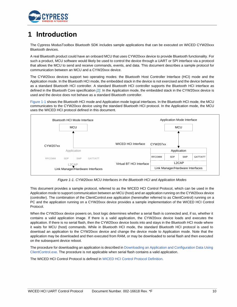
Figure 1-1 shows the Bluetooth HCI mode and Application mode logical interfaces. In the Bluetooth HCI mode, the MCU
communicates to the CYW20xxx device using the standard Bluetooth HCI protocol. In the Application mode, the MCU
uses the WICED HCI protocol defined in this document.
MCU MCU
Application
RFCOMM SDP SMP GATT/ATT
L2CAP
Link Manager/Hardware Interfaces
Bluetooth HCI Mode Interface Application Mode Interface
CYW207xxWICED HCI Interface
Virtual BT HCI Interface
Link Manager/Hardware Interfaces
Application
RFCOMM SDP SMP GATT/ATT
L2CAP
CYW207xx
Figure 1-1. CYW20xxx MCU Interfaces in the Bluetooth HCI and Application Modes
This document provides a sample protocol, referred to as the WICED HCI Control Protocol, which can be used in the
Application mode to support communication between an MCU (host) and an application running on the CYW20xxx device
(controller). The combination of the ClientControl.exe application (hereinafter referred to as ClientControl) running on a
PC and the application running on a CYW20xxx device provides a sample implementation of the WICED HCI Control
Protocol.
When the CYW20xxx device powers on, boot logic determines whether a serial flash is connected and, if so, whether it
contains a valid application image. If there is a valid application, the CYW20xxx device loads and executes the
application. If there is no serial flash, then the CYW20xxx device boots into and stays in the Bluetooth HCI mode where
it waits for MCU (host) commands. While in Bluetooth HCI mode, the standard Bluetooth HCI protocol is used to
download an application to the CYW20xxx device and change the device mode to Application mode. Note that the
application may be downloaded and then executed from RAM, or may be downloaded to serial flash and then executed
on the subsequent device reboot.
The procedure for downloading an application is described in Downloading an Application and Configuration Data Using
ClientControl.exe. The procedure is not applicable when serial flash contains a valid application.
The WICED HCI Control Protocol is defined in WICED HCI Control Protocol Definition.
Downloading an Application and Configuration Data
WICED HCI UART Control Protocol Document Number. 002-16618 Rev. *F 11
2 Downloading an Application and Configuration Data
2.1 Introduction
This section describes the process of downloading an application to a CYW20xxx device. The first scenario describes
the use of a ClientControl.exe application executing on a host PC (in place of a host MCU) to download an embedded
application and its associated configuration data to RAM in a CYW20xxx device. The second scenario describes the
WICED build and download process, which writes application and configuration data to serial flash before restarting the
CYW20xxx device.
Downloading to RAM (the first scenario) is not supported by CYW20xxx devices that have On-Chip-Flash (OCF). These
devices include the CYW20719, CYW20721, CYW20819, and CYW20820. OCF devices only support downloading to
serial flash (the second scenario). See sections 2.4 and 2.5 for details on each scenario.
Note: The code present in the ROM is in most cases sufficient to perform the download. In some cases, the MCU needs
to load the minidriver which is used during the remainder of the download process. The minidriver is a set of code and
data that replaces the download code in the ROM of the CYW20xxx device. The minidriver download provides a way to
adapt the download process to handle scenarios that the ROM code does not. For example, a design using the CYW20xxx
may require downloading to a serial flash that requires a different protocol than the ROM can supply. Downloading a
minidriver that supports this protocol prior to downloading the application would solve this situation. Minidrivers are not
required and are not supplied for some platforms. Minidrivers are optional and specific to each platform and when they
are supplied can be found in the platforms subdirectories of the wiced_btsdk project (created when creating any WICED
board application with ModusToolbox). For example, the CYW20819 minidriver can be found here:
<USER_HOME>\mtw\wiced_btsdk\dev-kit\20819A1\platforms\minidriver-20819A1-uart-patchram.hex
Note that the Vendor Specific HCI commands described in this section have address and length fields in little-endian byte
order.
2.2 Preparing for HCI Commands
When the device is initially powered on the boot code will attempt to identify the hardware interface to be used for HCI communication. For UART, the device behavior depends on the state of CTS when RST_N is de-asserted. If CTS is LOW at this time, the device enters the autobaud state (download mode). If CTS is HIGH after reset, the device will check NVRAM and apply any stored configuration, typically ending in a mode ready to accept all HCI commands at a default baud rate. If no configuration is available, the device will also enter autobaud mode.
The autobaud mode will attempt to detect the UART baud rate by checking the RX line for the bit pattern of an HCI_RESET
command. When detected, the HCI_RESET response is given at the same baud rate. In this mode, most HCI commands will
have no response. The HCI_DOWNLOAD_MINIDRIVER command, described in point 4 in HCI Commands and Events During
a RAM Download, will also have no response when the device is in autobaud mode. To download to the device in this mode, ignore the “no response” to HCI_DOWNLOAD_MINIDRIVER and proceed with the download procedures as described sections
2.4 through 2.5.1.
2.3 Download File Formats
Download images are kept in *.hcd or *.hex files. The *.hcd is more typically used for RAM downloads and the *.hex format
is typically used for flash downloads. Each file format must be parsed and converted to HCI commands to successfully
transfer the image to the device. During download operations to reference boards controlled by ModusToolbox, the
ChipLoad application performs these operations.
The *.hcd format consists of binary records that can be parsed and interpreted directly as HCI commands:
1. The first two binary bytes are the command identifier, for example, the HCI_WRITE command, described in point 5 in
HCI Commands and Events During a RAM Download,12 is represented by binary bytes 0x4c, 0xfc.
Downloading an Application and Configuration Data
WICED HCI UART Control Protocol Document Number. 002-16618 Rev. *F 12
2. The following byte is the command payload length. For example, a binary 0x6 indicates that six more bytes to follow will complete the command.
3. The command payload follows, in binary bytes.
To convert the file successfully to HCI commands, only the transport indication needs to be added. For example, when
using UART transport, the hex byte 0x1 should precede any HCI command to indicate that it is a command rather than
an event. The detailed specifications for HCI transport are publicly available.
The *.hex format follows the Intel I32HEX conventions that are widely documented and can be found on Wikipedia, for
example. The format consists of records delimited by ASCII carriage return and line feed (0xd, 0xa), but each record also
has a start indicator, as described below.
1. Start code “:”, ASCII 0x3a.
2. Byte count in record payload as two hexadecimal digits, for example ‘FF’ is a count of 255.
3. Address as four hexadecimal digits, for example ‘1000’ would represent 0x1000 or 4096.
4. Record type as two hexadecimal digits. The record types used for download images are:
a. ‘00’ for data record, where address field represents low 16-bits of image destination
b. ‘01’ for end of file (last record), the payload is zero bytes in length and the address field is not used and set as
‘0000’
c. ‘04’ for extended address (high 16 bits of subsequent data record addresses)
d. ‘05’ for a 32-bit address. The record address field is left at ‘0000’, the length is ‘04’ bytes, and the eight hexadecimal
data digits are interpreted as a 32-bit address. For example, ‘00220001’ would be the address 0x220001. This
record is often used to indicate a LAUNCH_RAM destination described below.
5. Record payload data represented as hexadecimal ASCII digits, two digits per byte and extending for the number of bytes indicated by the record’s byte count.
6. Checksum of the entire preceding record data represented as two hexadecimal ASCII digits.
When the *.hex file is parsed, the data record payloads will resolve into one or more blocks of continuous data. When
more than one block of data is present, there will be a discontinuity in the record addresses. The address gap may be
described by a ‘04’ record, used to reset the upper 16-bits of address, followed by ‘00’ type data records forming the next
block of data. Contiguous data blocks should be collected and segmented to form HCI WRITE_RAM download command
payloads as described in point 5 in HCI Commands and Events During a RAM Download.
2.4 Downloading the Application to RAM
Note: this scenario is not supported for CYW20xxx devices that support OCF, see section 2.1.
To download a target application to the CYW20xxx device, perform the following steps:
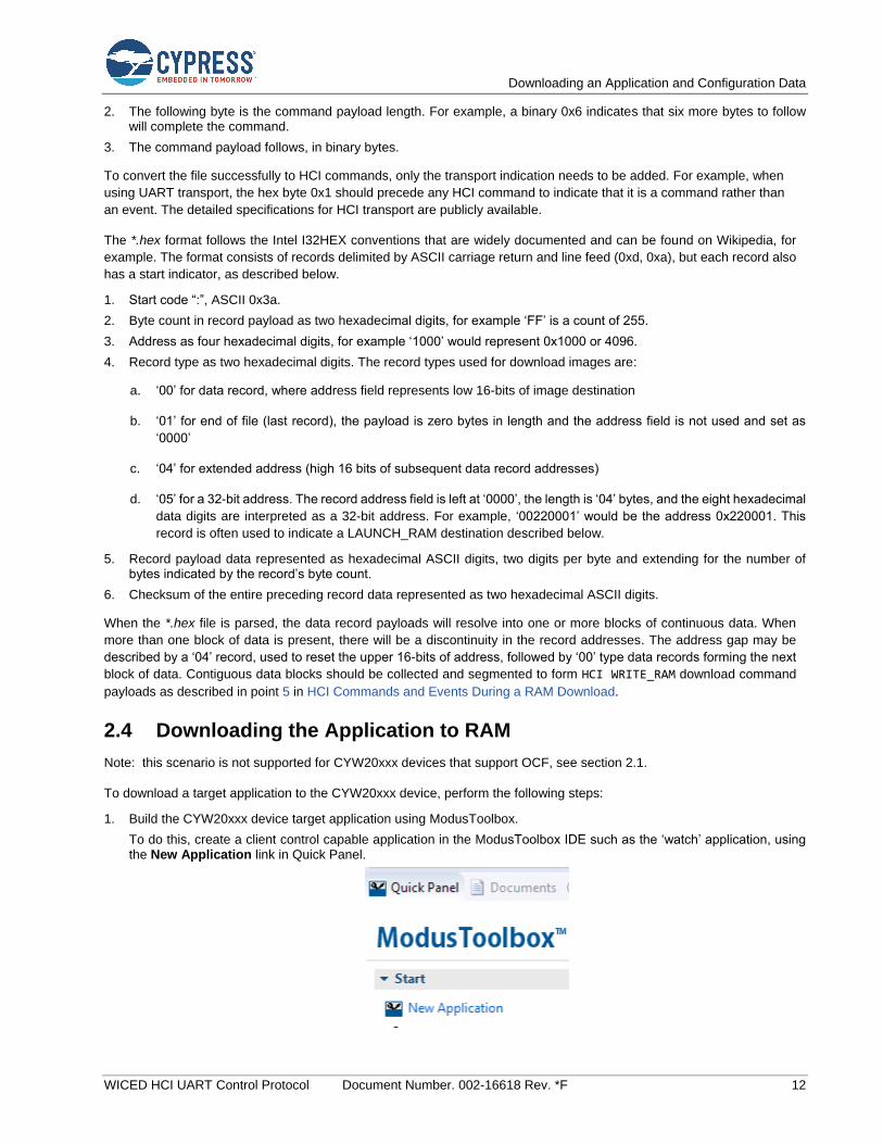
1. Build the CYW20xxx device target application using ModusToolbox.
To do this, create a client control capable application in the ModusToolbox IDE such as the ‘watch’ application, using the New Application link in Quick Panel.
Downloading an Application and Configuration Data
WICED HCI UART Control Protocol Document Number. 002-16618 Rev. *F 13
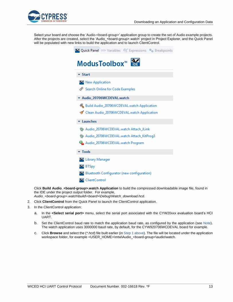
Select your board and choose the ‘Audio-<board-group>’ application group to create the set of Audio example projects. After the projects are created, select the ‘Audio_<board-group>.watch’ project in Project Explorer, and the Quick Panel will be populated with new links to build the application and to launch ClientControl.
Click Build Audio_<board-group>.watch Application to build the compressed downloadable image file, found in the IDE under the project output folder. For example, Audio_<board-group>.watch\build\<board>\Debug\Watch_download.hcd.
2. Click ClientControl from the Quick Panel to launch the ClientControl application.
3. In the ClientControl application:
a. In the <Select serial port> menu, select the serial port associated with the CYW20xxx evaluation board’s HCI UART.
b. Set the ClientControl baud rate to match the application baud rate, as configured by the application (see Note). The watch application uses 3000000 baud rate, by default, for the CYW920706WCDEVAL board for example.
c. Click Browse and select the (*.hcd) file built earlier (in Step 1 above). The file will be located under the application workspace folder, for example <USER_HOME>\mtw\Audio_<board-group>\audio\watch.
Downloading an Application and Configuration Data
WICED HCI UART Control Protocol Document Number. 002-16618 Rev. *F 14
(d) (c)
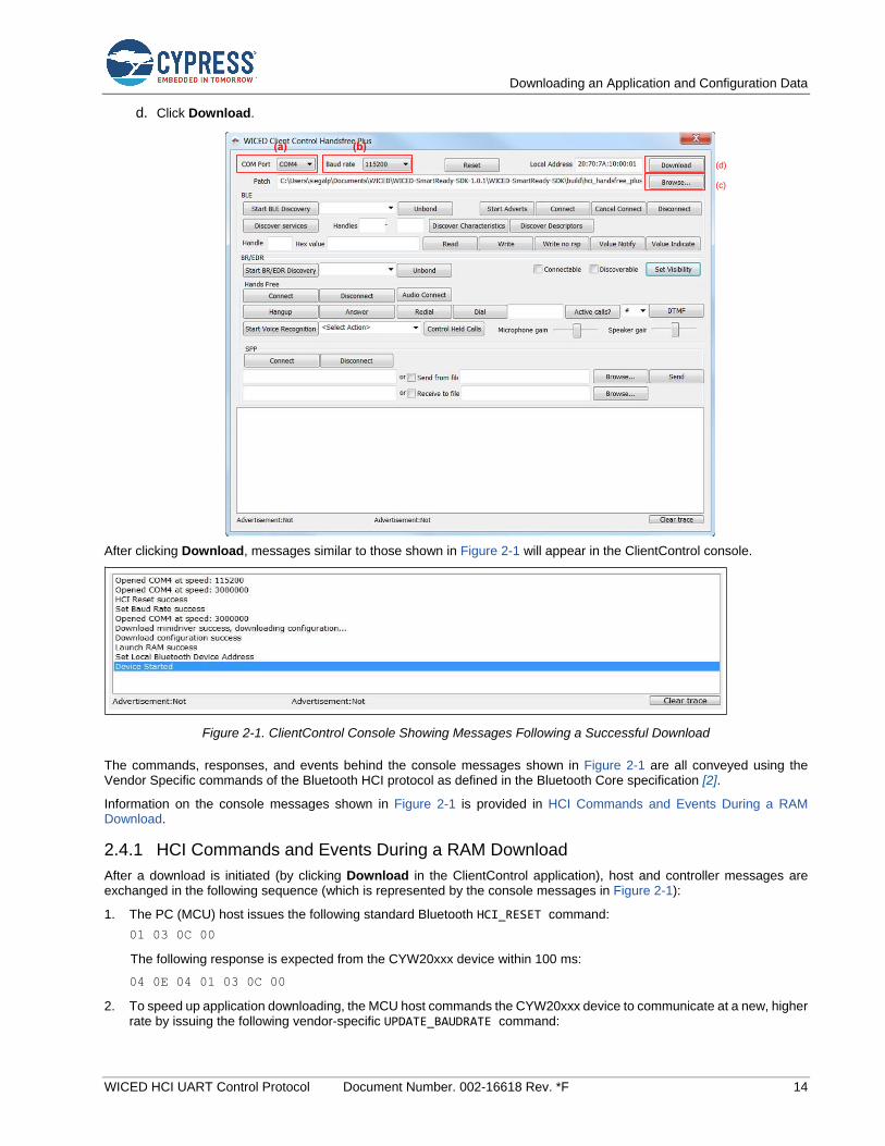
d. Click Download.
After clicking Download, messages similar to those shown in Figure 2-1 will appear in the ClientControl console.
Figure 2-1. ClientControl Console Showing Messages Following a Successful Download
The commands, responses, and events behind the console messages shown in Figure 2-1 are all conveyed using the Vendor Specific commands of the Bluetooth HCI protocol as defined in the Bluetooth Core specification [2].
Information on the console messages shown in Figure 2-1 is provided in HCI Commands and Events During a RAM Download.
2.4.1 HCI Commands and Events During a RAM Download
After a download is initiated (by clicking Download in the ClientControl application), host and controller messages are exchanged in the following sequence (which is represented by the console messages in Figure 2-1):
1. The PC (MCU) host issues the following standard Bluetooth HCI_RESET command:
01 03 0C 00
The following response is expected from the CYW20xxx device within 100 ms:
04 0E 04 01 03 0C 00
2. To speed up application downloading, the MCU host commands the CYW20xxx device to communicate at a new, higher rate by issuing the following vendor-specific UPDATE_BAUDRATE command:

Downloading an Application and Configuration Data
WICED HCI UART Control Protocol Document Number. 002-16618 Rev. *F 15
01 18 FC 06 00 00 xx xx xx xx
In the above command, the xx xx xx xx bytes specify the 32-bit little-endian value of the new rate in bits per second.
For example, 115200 is represented as 00 C2 01 00.
The following response to the UPDATE_BAUDRATE command is expected within 100 ms:
04 0E 04 01 18 FC 00
3. The host switches to the new baud rate after receiving the response at the old baud rate.
4. If successful, the host issues the following DOWNLOAD_MINIDRIVER vendor-specific command:
01 2E FC 00
The following response is expected from the CYW20xxx device within 100 ms:
04 0E 04 01 2E FC 00
If there is not response to the DOWNLOAD_MINIDRIVER command, the device may be in autobaud mode (see Preparing
for HCI Commands). While it is required to send the DOWNLOAD_MINIDRIVER command, it is optional to download a
minidriver itself. The ROM download code behavior is sufficient to perform the download for most cases. For these cases, the download process continues directly to step 5 to download the application image.
If needed, the minidriver is loaded using WRITE_RAM vendor-specific commands, as described in step 5. The hex file
format indicates the RAM address for each data chunk in the file. Data chunks from the file can be grouped up to the payload size of the WRITE_RAM command. To start the minidriver, use a LAUNCH_RAM command, as described in step
6, to begin minidriver execution at the first address of the minidriver image. For example, if the minidriver download starts at 0x220000, then the LAUNCH_RAM command should use 0x220000 as the launch address. After launching the
minidriver, continue the application download process with step 5.
5. After optionally downloading the minidriver, the host writes application code and configuration data to the CYW20xxx device by sending WRITE_RAM Vendor Specific commands. Since the writes are destined for the CYW20xxx device’s
RAM, the destination addresses in the WRITE_RAM commands are absolute RAM locations.
The following WRITE_RAM command is an example:
01 4C FC nn xx xx xx xx yy yy yy …
In the above WRITE_RAM command:
nn is 4 + N, which represents 4 address bytes plus N payload bytes.
xx xx xx xx is the 4-byte, absolute RAM address.
yy yy yy … are the N payload bytes to be loaded into the addressed RAM location.
The following response to each WRITE_RAM command is expected within 200 ms:
04 0E 04 01 4C FC 00
6. After the host has written all application and configuration data to RAM, it sends a LAUNCH_RAM command with the
address stored in the last record of the hardware configuration data (HCD) file.
An example LAUNCH_RAM command is shown here:
01 4E FC 04 xx xx xx xx
In the above LAUNCH_RAM command, xx xx xx xx is the 4-byte absolute RAM address of the last HCD record.
Typically, the last address is 0xFFFFFFFF.
The following response to the LAUNCH_RAM command is expected within 200 ms:
04 0E 04 01 4E FC 00
Note: Following a successful LAUNCH_RAM command, the device is in the Application mode and the application is running.
Note: In the Application mode, the UART configuration depends on the application. If the application sets the baud rate to 3 Mbps at start-up then the MCU or ClientControl.exe running on a PC must also configure the UART for 3 Mbps operation to successfully communicate with the CYW20xxx device. The application sets the baud rate using the following command: uart_SetBaudrate(0, 0, 3000000). The default application baud rate is configured in the call to
wiced_transport_init(). To set the UART rate via the host, see Set Baud Rate.

Downloading an Application and Configuration Data
WICED HCI UART Control Protocol Document Number. 002-16618 Rev. *F 16
2.5 Downloading the Application to Serial Flash
To download a target application automatically to the CYW20xxx device using the ModusToolbox IDE, use the Program
launch link in the Quick Panel (see Downloading the Application to RAM).
The IDE will attempt to download to the serial port associated with the CYW20xxx evaluation board’s HCI UART:
If the serial port is not already identified, the build process searches available ports for the target device at several baud rates. If the device does not respond to HCI commands at this time, the download process will fail. A manual board reset or recovery procedure may be needed to restore the board to Bluetooth HCI mode. See the Kit Guide [1] for your device for recovery procedure information.
Once the port is identified, the build process begins the download procedure with an image file located under the ModusToolbox installation folder at a path similar to the following for CYW20819:
<USER_HOME>\mtw\Audio_<board-group>\audio\watch\build\<board>\Debug\Watch_download.hex
Note that the hex file format consists of records that include data and address information. For serial flash download hex files, the addresses used map to offsets in the flash device. For example, CYW20706 and CYW20735 hex records map the address 0xFF000000 to the base, or 0, offset in the attached serial flash device. Similarly, the CYW20719 and CYW20819 use 0x00500000 as the base address for the on-chip flash.
Note that the vendor-specific HCI commands READ_RAM, WRITE_RAM, and LAUNCH_RAM are not limited to actual RAM
address ranges. The same commands are used to write to non-volatile storage like serial flash by using mapped
addresses that correspond to offsets within these devices.
2.5.1 HCI Commands and Events During a Serial Flash Download
This section describes the protocol for the download process described above for the situations when an MCU needs to
load the image to the serial flash attached to the CYW20xxx device.
During the download process, the host and controller exchange messages in the following sequence:
1. The PC (MCU) host issues the following standard Bluetooth HCI_RESET command:
01 03 0C 00
The following response is expected from the CYW20xxx device within 100 ms:
04 0E 04 01 03 0C 00
2. To speed up application downloading, the MCU host commands the CYW20xxx device to communicate at a new, higher rate by issuing the following vendor-specific UPDATE_BAUDRATE command:
01 18 FC 06 00 00 xx xx xx xx
In the above command, the xx xx xx xx bytes specify the 32-bit value of the new rate in bits per second. For example,
115200 is represented as 00 C2 01 00.
The following response to the UPDATE_BAUDRATE command is expected within 100 ms:
04 0E 04 01 18 FC 00
3. The host switches to the new baud rate after receiving the response at the old baud rate.
4. If successful, the host issues the following DOWNLOAD_MINIDRIVER command:
01 2E FC 00
The following response is expected from the CYW20xxx device within 100 ms:
04 0E 04 01 2E FC 00
If there is not response to the DOWNLOAD_MINIDRIVER command, the device may be in autobaud mode (see Preparing
for HCI Commands). While it is required to send the DOWNLOAD_MINIDRIVER command, it is optional to download a
minidriver itself. The ROM download code behavior is sufficient to perform the download for some cases. For these cases, the download process continues directly to step 5 to download the application image.
If needed, the minidriver is loaded using WRITE_RAM vendor-specific commands, as described in step 5. The hex file
format indicates the RAM address for each data chunk in the file. Data chunks from the file can be grouped up to the payload size of the WRITE_RAM command. To start the minidriver, use a LAUNCH_RAM command, as described in
Downloading an Application and Configuration Data
WICED HCI UART Control Protocol Document Number. 002-16618 Rev. *F 17
step 8, to begin minidriver execution at the first address of the minidriver image. For example, if the minidriver download starts at 0x220000, then the LAUNCH_RAM command should use 0x220000 as the launch address. After
launching the minidriver, continue the application download process with step 5.
5. After downloading the minidriver, the CHIP_ERASE command is sent. If it is desirable to preserve some data in flash and
only erase sectors that will be written, this step may be skipped.
Note: a SECTOR_ERASE command is also available for scenarios where only certain targeted sectors need to be erased,
though that is not part of the download procedure. Contact Cypress support for information if that advanced functionality is needed.
The following CHIP_ERASE command is an example:
01 CE FF 04 xx xx xx xx
In the above CHIP_ERASE command, xx xx xx xx is the 4-byte address indicating the range of the non-volatile
memory to be erased. A special value of EF EE BE FC (0xFCBEEEEF) is used to signal “use the lowest valid non-
volatile memory range”. Otherwise, the device to be erased is determined from the value when compared to valid ranges, where 0x500000 would be the start of on-chip flash when supported and 0xFF000000 would be the start of off-chip flash.
6. After optionally downloading the mini-driver and performing CHIP_ERASE, the host writes application code and
configuration data to the CYW20xxx device by sending WRITE_RAM commands.
The following WRITE_RAM command is an example:
01 4C FC nn xx xx xx xx yy yy yy …
In the above WRITE_RAM command:
a. nn is 4 + N, which represents 4 address bytes plus N payload bytes.
b. xx xx xx xx is the 4-byte, mapped address for serial flash offset.
c. yy yy yy … are the N payload bytes to be loaded into the mapped address. The following response to each
WRITE_RAM command is expected within 200 ms:
04 0E 04 01 4C FC 00
7. After the host has written application and configuration data to flash, it can be validated with a CRC check command. Also, any block can be read back using the READ_RAM command.
a. CRC method: return the CRC-32 calculated by reading the data range indicated in the command. The following
CRC validation command is an example:
01 CC FC 08 xx xx xx xx yy yy yy yy
In the above command, the xx xx xx xx bytes specify the 32-bit value of the mapped address for the serial flash
offset and the yy yy yy yy bytes specify the 32-bit value of the number of bytes to be read from the serial flash for
the CRC calculation.
The following response is expected after the READ_RAM command:
04 0E 08 01 CC FC 00 xx xx xx xx
In the above response, the xx bytes are the 32-bit CRC-32 value calculated by reading the data bytes from flash
starting at the virtual address given in the CRC command and continuing for the number of bytes provided in the
CRC command.
b. The following READ_RAM command is an example:
01 4D FC 05 xx xx xx xx yy
In the above command, the xx xx xx xx bytes specify the value of the serial flash offset’s mapped address and
the yy byte specifies the length of data to be read.
The following response is expected within 100 milliseconds of the READ_RAM command:
04 0E xx 01 4D FC 00 yy yy yy …
In the above response, the xx byte represents N+4, where N is the number of data bytes read from the flash. The
yy bytes are the actual data read back from the mapped offset.

Downloading an Application and Configuration Data
WICED HCI UART Control Protocol Document Number. 002-16618 Rev. *F 18
8. After the host has written and validated all application and configuration data to RAM, it sends a LAUNCH_RAM command
with the special destination address specifying reboot for the device, typically 0xFFFFFFFF.
An example LAUNCH_RAM command is shown here:
01 4E FC 04 xx xx xx xx
In the above command, the xx xx xx xx bytes represent the destination address for the CPU branch.
The following response to the LAUNCH_RAM command is expected within 200 ms:
04 0E 04 01 4E FC 00
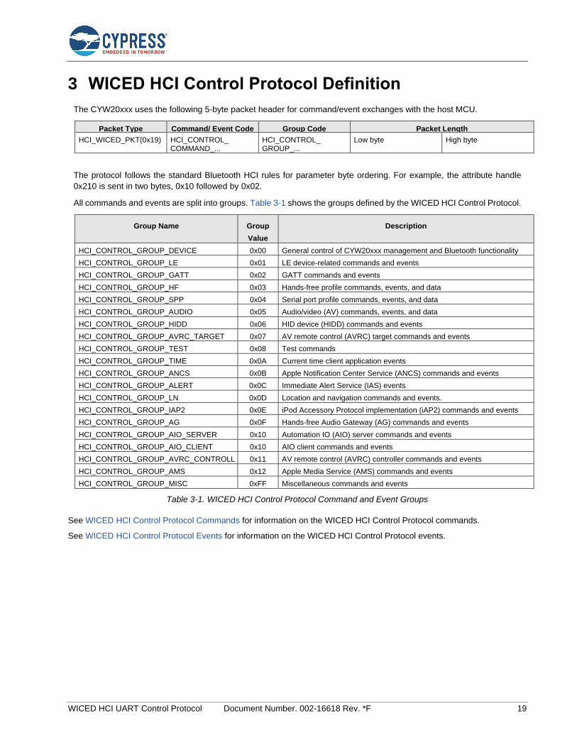
WICED HCI UART Control Protocol Document Number. 002-16618 Rev. *F 19
3 WICED HCI Control Protocol Definition
The CYW20xxx uses the following 5-byte packet header for command/event exchanges with the host MCU.
Packet Type Command/ Event Code Group Code Packet Length
HCI_WICED_PKT(0x19) HCI_CONTROL_ COMMAND_...
HCI_CONTROL_ GROUP_...
Low byte High byte
The protocol follows the standard Bluetooth HCI rules for parameter byte ordering. For example, the attribute handle
0x210 is sent in two bytes, 0x10 followed by 0x02.
All commands and events are split into groups. Table 3-1 shows the groups defined by the WICED HCI Control Protocol.
Group Name Group
Value
Description
HCI_CONTROL_GROUP_DEVICE 0x00 General control of CYW20xxx management and Bluetooth functionality
HCI_CONTROL_GROUP_LE 0x01 LE device-related commands and events
HCI_CONTROL_GROUP_GATT 0x02 GATT commands and events
HCI_CONTROL_GROUP_HF 0x03 Hands-free profile commands, events, and data
HCI_CONTROL_GROUP_SPP 0x04 Serial port profile commands, events, and data
HCI_CONTROL_GROUP_AUDIO 0x05 Audio/video (AV) commands, events, and data
HCI_CONTROL_GROUP_HIDD 0x06 HID device (HIDD) commands and events
HCI_CONTROL_GROUP_AVRC_TARGET 0x07 AV remote control (AVRC) target commands and events
HCI_CONTROL_GROUP_TEST 0x08 Test commands
HCI_CONTROL_GROUP_TIME 0x0A Current time client application events
HCI_CONTROL_GROUP_ANCS 0x0B Apple Notification Center Service (ANCS) commands and events
HCI_CONTROL_GROUP_ALERT 0x0C Immediate Alert Service (IAS) events
HCI_CONTROL_GROUP_LN 0x0D Location and navigation commands and events.
HCI_CONTROL_GROUP_IAP2 0x0E iPod Accessory Protocol implementation (iAP2) commands and events
HCI_CONTROL_GROUP_AG 0x0F Hands-free Audio Gateway (AG) commands and events
HCI_CONTROL_GROUP_AIO_SERVER 0x10 Automation IO (AIO) server commands and events
HCI_CONTROL_GROUP_AIO_CLIENT 0x10 AIO client commands and events
HCI_CONTROL_GROUP_AVRC_CONTROLLER
0x11 AV remote control (AVRC) controller commands and events
HCI_CONTROL_GROUP_AMS 0x12 Apple Media Service (AMS) commands and events
HCI_CONTROL_GROUP_MISC 0xFF Miscellaneous commands and events
Table 3-1. WICED HCI Control Protocol Command and Event Groups
See WICED HCI Control Protocol Commands for information on the WICED HCI Control Protocol commands.
See WICED HCI Control Protocol Events for information on the WICED HCI Control Protocol events.

WICED HCI Control Protocol Commands
WICED HCI UART Control Protocol Document Number. 002-16618 Rev. *F 20
4 WICED HCI Control Protocol Commands
4.1 Device Commands: HCI_CONTROL_GROUP_DEVICE
The device commands allow the host to manage the behavior of the CYW20xxx.
4.1.1 Reset
The Reset command causes the CYW20xxx to restart. After initialization completes, the CYW20xxx sends a Device Started event (see Device Started).
Item Description
Operating code 0x01
Parameters –
Table 4-1. Reset Command
4.1.2 Trace Enable
The Trace Enable command instructs the CYW20xxx to start or stop forwarding the WICED logs and virtual HCI traces.
The CYW20xxx provides the following two trace types:
An output of the WICED_BT_TRACE statements.
A binary dump of the virtual HCI commands, events, and data packets between the embedded host stack and the CYW20xxx controller.
The WICED_BT_TRACE output is forwarded in the HCI_CONTROL_EVENT_WICED_TRACE when a corresponding trace is enabled.
The virtual HCI traces are sent over UART using HCI_CONTROL_EVENT_HCI_DATA.
Item Description
Operating code 0x02
Parameters Bluetooth HCI trace enable (1 byte)
If true, HCI traces are routed through the WICED HCI interface to the host.
WICED trace route (1 byte)
0: Traces are not generated.
1: Traces are forwarded to the WICED UART.
2: Traces are forwarded to the HCI UART.
3: Traces are forwarded to the debug UART.
4: Traces are forwarded to the peripheral UART.
Table 4-2. Trace Enable Command
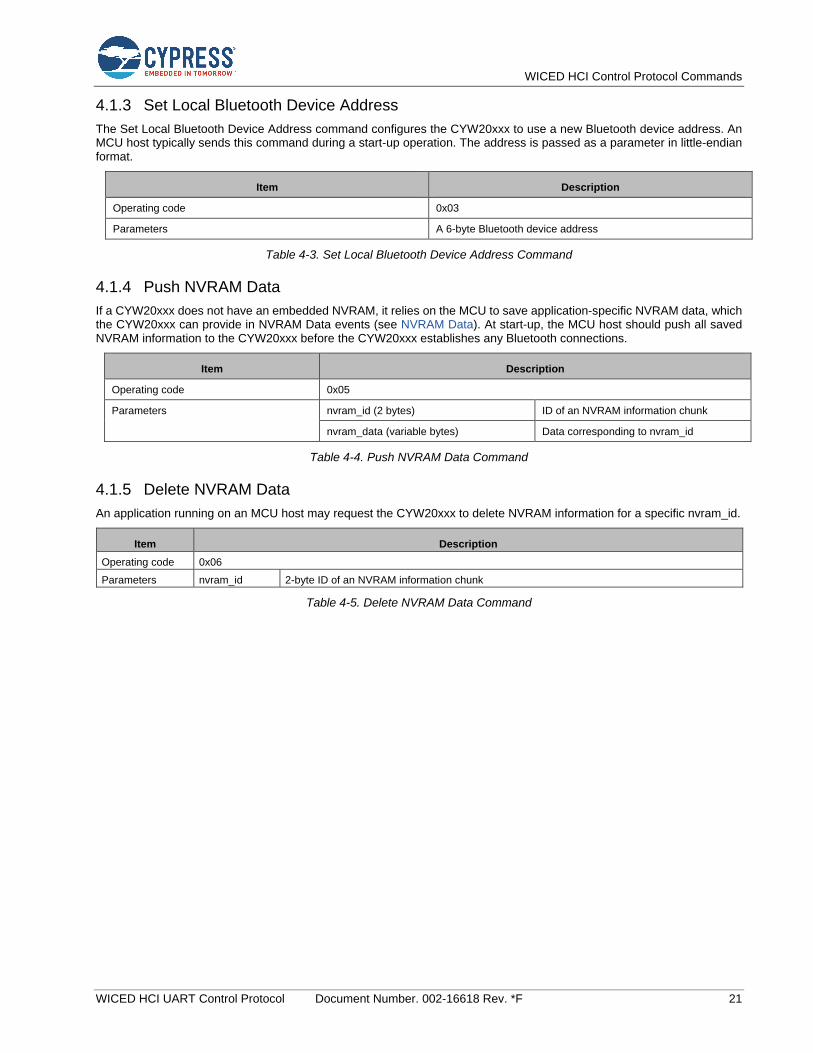
WICED HCI Control Protocol Commands
WICED HCI UART Control Protocol Document Number. 002-16618 Rev. *F 21
4.1.3 Set Local Bluetooth Device Address
The Set Local Bluetooth Device Address command configures the CYW20xxx to use a new Bluetooth device address. An MCU host typically sends this command during a start-up operation. The address is passed as a parameter in little-endian format.
Item Description
Operating code 0x03
Parameters A 6-byte Bluetooth device address
Table 4-3. Set Local Bluetooth Device Address Command
4.1.4 Push NVRAM Data
If a CYW20xxx does not have an embedded NVRAM, it relies on the MCU to save application-specific NVRAM data, which the CYW20xxx can provide in NVRAM Data events (see NVRAM Data). At start-up, the MCU host should push all saved NVRAM information to the CYW20xxx before the CYW20xxx establishes any Bluetooth connections.
Item Description
Operating code 0x05
Parameters nvram_id (2 bytes) ID of an NVRAM information chunk
nvram_data (variable bytes) Data corresponding to nvram_id
Table 4-4. Push NVRAM Data Command
4.1.5 Delete NVRAM Data
An application running on an MCU host may request the CYW20xxx to delete NVRAM information for a specific nvram_id.
Item Description
Operating code 0x06
Parameters nvram_id 2-byte ID of an NVRAM information chunk
Table 4-5. Delete NVRAM Data Command
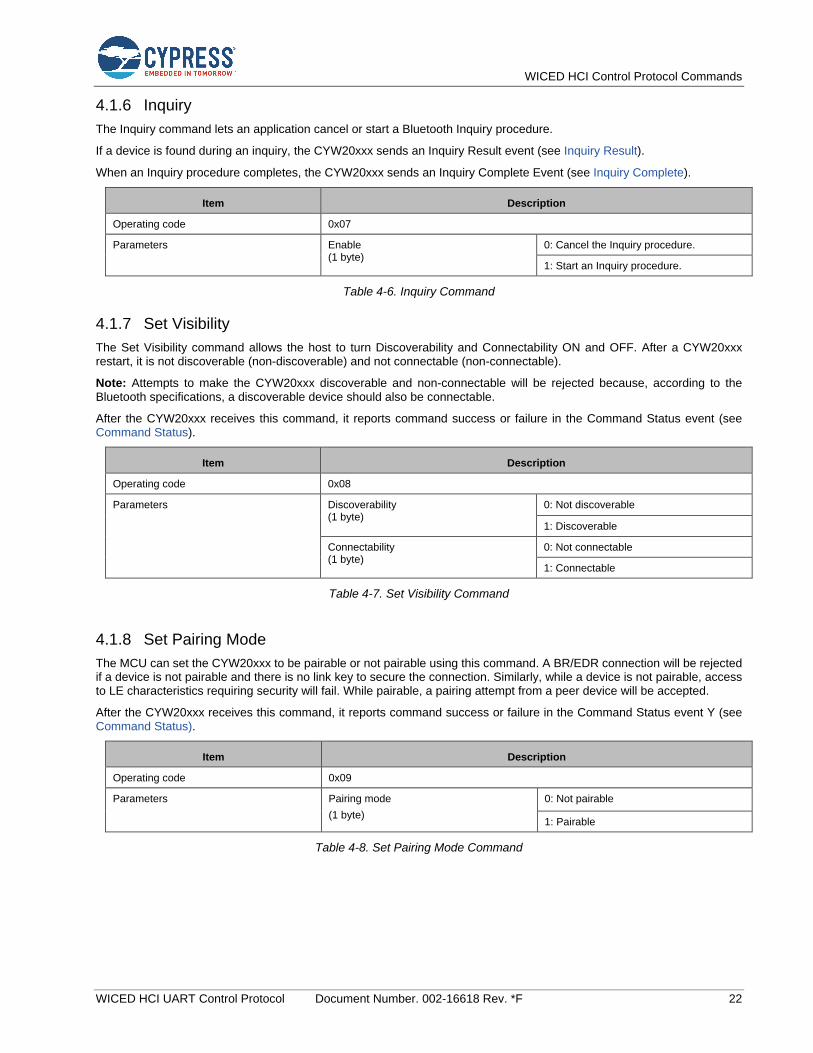
WICED HCI Control Protocol Commands
WICED HCI UART Control Protocol Document Number. 002-16618 Rev. *F 22
4.1.6 Inquiry
The Inquiry command lets an application cancel or start a Bluetooth Inquiry procedure.
If a device is found during an inquiry, the CYW20xxx sends an Inquiry Result event (see Inquiry Result).
When an Inquiry procedure completes, the CYW20xxx sends an Inquiry Complete Event (see Inquiry Complete).
Item Description
Operating code 0x07
Parameters Enable (1 byte)
0: Cancel the Inquiry procedure.
1: Start an Inquiry procedure.
Table 4-6. Inquiry Command
4.1.7 Set Visibility
The Set Visibility command allows the host to turn Discoverability and Connectability ON and OFF. After a CYW20xxx restart, it is not discoverable (non-discoverable) and not connectable (non-connectable).
Note: Attempts to make the CYW20xxx discoverable and non-connectable will be rejected because, according to the Bluetooth specifications, a discoverable device should also be connectable.
After the CYW20xxx receives this command, it reports command success or failure in the Command Status event (see Command Status).
Item Description
Operating code 0x08
Parameters Discoverability (1 byte)
0: Not discoverable
1: Discoverable
Connectability (1 byte)
0: Not connectable
1: Connectable
Table 4-7. Set Visibility Command
4.1.8 Set Pairing Mode
The MCU can set the CYW20xxx to be pairable or not pairable using this command. A BR/EDR connection will be rejected if a device is not pairable and there is no link key to secure the connection. Similarly, while a device is not pairable, access to LE characteristics requiring security will fail. While pairable, a pairing attempt from a peer device will be accepted.
After the CYW20xxx receives this command, it reports command success or failure in the Command Status event Y (see Command Status).
Item Description
Operating code 0x09
Parameters Pairing mode
(1 byte)
0: Not pairable
1: Pairable
Table 4-8. Set Pairing Mode Command

WICED HCI Control Protocol Commands
WICED HCI UART Control Protocol Document Number. 002-16618 Rev. *F 23
4.1.9 Unbond
The MCU can use this command to instruct the CYW20xxx to remove bonding information (that is, security keys) for the device whose Bluetooth device address is passed as a parameter.
After the CYW20xxx receives this command, it reports command success or failure in the Command Status event (see Command Status).
Item Description
Operating code 0x0A
Parameters Address
(6 bytes)
Bluetooth device address
Table 4-9. Unbond Command
4.1.10 User Confirmation
The MCU should send this command after it receives a User Confirmation Request event (see User Confirmation Request) from the CYW20xxx to accept or reject pairing. It is assumed that an MCU will display the numeric comparison code provided in the User Confirmation Request event and a user will provide the yes/no input that will be passed to the CYW20xxx as the User Confirmation command.
Item Description
Operating code 0x0B
Parameters Address (6 bytes)
Bluetooth device address
Accept/Reject (1 byte)
0: Reject pairing, or the numeric comparison code does not match.
1: Accept pairing
Table 4-10. User Confirmation Command
4.1.11 Enable Coexistence
This command allows an MCU to enable the coexistence functionality in designs that include BT/BLE and WiFi applications.
Item Description
Operating code 0x0C
Parameters –
Table 4-11. Enable Coexistence Command
4.1.12 Disable Coexistence
This command allows an MCU to disable the coexistence functionality in designs that include BT/BLE and WiFi applications.
Item Description
Operating code 0x0D
Parameters –
Table 4-12. Disable Coexistence Command

WICED HCI Control Protocol Commands
WICED HCI UART Control Protocol Document Number. 002-16618 Rev. *F 24
4.1.13 Set Battery Level
This miscellaneous command allows the MCU to set the battery level in the GATT database of the CYW20xxx. A connected peer device can read the battery level using a standard ATT read operation.
Item Description
Operating code 0x0E
Parameters Battery level (1 byte) Remaining battery capacity as a percentage (1 to 100).
Table 4-13. Set Battery Level Command
4.1.14 Read Local Bluetooth Device Address
The MCU can send this command to read the local Bluetooth Device Address of the CYW20xxx. When the CYW20xxx receives this command, it responds with the Read Local BDA Event message containing the Bluetooth Device Address.
Item Description
Operating code 0x0F
Parameters -
Table 4-14. Read Local Bluetooth Device Address Command
4.1.15 Start Bond
The MCU can send this command to initiate bonding with an unbonded device.
Item Description
Operating code 0x10
Parameters Address (6 bytes)
Transport (1 byte) 1 = BR/EDR, 2 = LE
Address Type (1 bytes) 0 = Public, 1 = Random (LE Only)
Table 4-15. Start Bond Command
4.1.16 Read Buffer Pool Usage Statistics
The MCU can send this command to read the buffer pool usage statistics to understand the buffer pool usage by the application running on the CYW20xxx, and to identify if there is a possibility of buffers running out for a given application use case. The Buffer Pool Usage Statistics event will be sent from the CYW20xxx to the MCU which includes the buffer pool usage statistics.
Item Description
Operating code 0x11
Parameters -
Table 4-16. Read Buffer Pool Usage Statistics Command
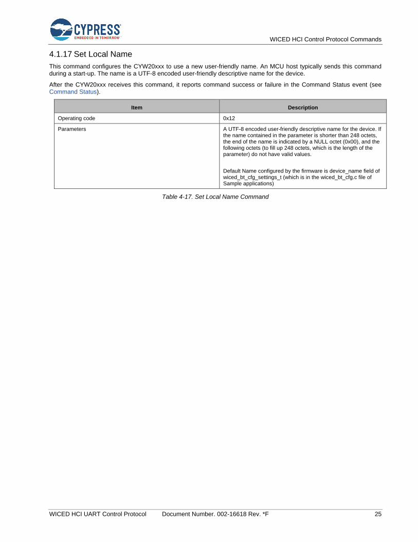
WICED HCI Control Protocol Commands
WICED HCI UART Control Protocol Document Number. 002-16618 Rev. *F 25
4.1.17 Set Local Name
This command configures the CYW20xxx to use a new user-friendly name. An MCU host typically sends this command during a start-up. The name is a UTF-8 encoded user-friendly descriptive name for the device.
After the CYW20xxx receives this command, it reports command success or failure in the Command Status event (see Command Status).
Item Description
Operating code 0x12
Parameters A UTF-8 encoded user-friendly descriptive name for the device. If the name contained in the parameter is shorter than 248 octets, the end of the name is indicated by a NULL octet (0x00), and the following octets (to fill up 248 octets, which is the length of the parameter) do not have valid values.
Default Name configured by the firmware is device_name field of wiced_bt_cfg_settings_t (which is in the wiced_bt_cfg.c file of Sample applications)
Table 4-17. Set Local Name Command
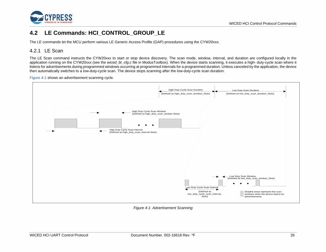
WICED HCI Control Protocol Commands
WICED HCI UART Control Protocol Document Number. 002-16618 Rev. *F 26
4.2 LE Commands: HCI_CONTROL_GROUP_LE
The LE commands let the MCU perform various LE Generic Access Profile (GAP) procedures using the CYW20xxx.
4.2.1 LE Scan
The LE Scan command instructs the CYW20xxx to start or stop device discovery. The scan mode, window, interval, and duration are configured locally in the application running on the CYW20xxx (see the wiced_bt_cfg.c file in ModusToolbox). When the device starts scanning, it executes a high- duty-cycle scan where it listens for advertisements during programmed windows occurring at programmed intervals for a programmed duration. Unless canceled by the application, the device then automatically switches to a low-duty-cycle scan. The device stops scanning after the low-duty-cycle scan duration.
Figure 4-1 shows an advertisement scanning cycle.
High Duty Cycle Scan Window
(Defined as high_duty_scan_window Slots)
High Duty Cycle Scan Interval
(Defined as high_duty_scan_interval Slots)
Low Duty Cycle Scan Interval
(Defined as
low_duty_cycle_scan_Interval_
Slots)
Low Duty Scan Window(Defined as low_duty_scan_window_Slots)
Shaded areas represent the scan
windows when the device listens for
advertisements.
Low Duty Scan Duration
(Defined as low_duty_scan_duration_Slots)
High Duty Cycle Scan Duration
(Defined as high_duty_scan_duration_Slots)
Figure 4-1. Advertisement Scanning

WICED HCI Control Protocol Commands
WICED HCI UART Control Protocol Document Number. 002-16618 Rev. *F 27
When the CYW20xxx receives and processes this command, it reports the scan state change in the Scan Status event (see LE Scan Status). Scan Status events are also sent when the CYW20xxx switches from a high-duty-cycle scan to a low-duty-cycle scan and from a low-duty-cycle scan to not scanning.
Item Description
Operating code 0x01
Parameters Enable (1 byte)
0: Stop device-discovery scanning.
1: Start device-discovery scanning.
Filter duplicates (1 byte)
0: Do not filter duplicate advertisements.
1: Filter duplicate advertisements.
Table 4-18. LE Scan Command
4.2.2 LE Advertise
The LE Advertise command instructs the CYW20xxx to stop or start sending advertisements. Typically, advertisements are sent so that a central-device peer can discover and optionally connect to a peripheral-device peer. When a CYW20xxx receives this command, it sends advertisements based on parameters configured in the wiced_bt_cfg_ble_advert_settings_t structure of the wiced_bt_cfg_settings_t structure (which is in the wiced_bt_cfg.c file of ModusToolbox).
Initially, advertisements are sent out using a programmed high-duty-cycle advertisement profile. After the high- duty-cycle duration (for example, high_duty_duration) expires, advertisements are sent out in accordance with a programmed low-duty-cycle advertisement profile, which also has a duration (for example, low_duty_duration). After the low_duty_duration, the CYW20xxx stops sending advertisements.
Figure 4-2 shows the high-duty-cycle and low-duty-cycle advertisement-sending profiles.
Low- Rate Interval
(Defined by low_duty_min_interval and
Low_duty_max_interval
High- Rate Duration(high_duty_duration)
Low- Rate Duration(low_duty_duration)
High-Rate Interval
(Defined by high_duty_min_interval and
High_duty_max_interval)
Figure 4-2. Advertisement-Sending Profile
When the CYW20xxx receives and processes this command, it reports advertisement state changes in the Advertisement State event (see LE Advertisement State). Advertisement State events are also sent when the CYW20xxx controller switches from the high-duty-cycle advertisements to low-duty-cycle advertisements and from low-duty-cycle advertisements to no advertisements.
Item Description
Operating code 0x02
Parameters Enable (1 byte)
0: Disable the ability to be discovered (that is, don’t send advertisements).
1: Enable the ability to be discovered (that is, send advertisements).
Table 4-19. LE Advertise Command
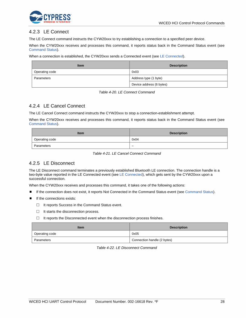
WICED HCI Control Protocol Commands
WICED HCI UART Control Protocol Document Number. 002-16618 Rev. *F 28
4.2.3 LE Connect
The LE Connect command instructs the CYW20xxx to try establishing a connection to a specified peer device.
When the CYW20xxx receives and processes this command, it reports status back in the Command Status event (see Command Status).
When a connection is established, the CYW20xxx sends a Connected event (see LE Connected).
Item Description
Operating code 0x03
Parameters Address type (1 byte)
Device address (6 bytes)
Table 4-20. LE Connect Command
4.2.4 LE Cancel Connect
The LE Cancel Connect command instructs the CYW20xxx to stop a connection-establishment attempt.
When the CYW20xxx receives and processes this command, it reports status back in the Command Status event (see Command Status).
Item Description
Operating code 0x04
Parameters –
Table 4-21. LE Cancel Connect Command
4.2.5 LE Disconnect
The LE Disconnect command terminates a previously established Bluetooth LE connection. The connection handle is a two-byte value reported in the LE Connected event (see LE Connected), which gets sent by the CYW20xxx upon a successful connection.
When the CYW20xxx receives and processes this command, it takes one of the following actions:
If the connection does not exist, it reports Not Connected in the Command Status event (see Command Status).
If the connections exists:
It reports Success in the Command Status event.
It starts the disconnection process.
It reports the Disconnected event when the disconnection process finishes.
Item Description
Operating code 0x05
Parameters Connection handle (2 bytes)
Table 4-22. LE Disconnect Command

WICED HCI Control Protocol Commands
WICED HCI UART Control Protocol Document Number. 002-16618 Rev. *F 29
4.2.6 LE Re Pair
This command instructs the CYW20xxx to delete link keys associated with a previously paired device and re-initiate a pairing sequence with that same device.
The NVRAM ID parameter should match the value reported to the MCU after the successful pairing in the NVRAM Data event (see NVRAM Data).
Item Description
Operating code 0x06
Parameters
Device address (6 bytes)
address of the device from the original pairing.
NVRAM ID (2 bytes) ID associated with the address of the device from the original pairing.
Table 4-23. LE Re Pair Command
4.2.7 LE Get Identity Address
When an initial connection with a peer is established, the MCU will receive a private random address (if a private random address is used) of the device in the LE Connection Up event message. The LE Get Identity Address command can be used by the MCU to retrieve the Identity Address, which is a public or a static random address of the peer device.
If an MCU attempts to retrieve the resolved identity address of the peer, then this command can be used. The resolved identity address of the peer will be returned in the LE Identity Address event message (see LE Identity Address).
Item Description
Operating code 0x07
Parameters Device address (6 bytes) Address of the peer device
Table 4-24. LE Get Identity Address Command
4.2.8 LE Set Channel Classification
The MCU can send this command to the CYW20xxx and set the channel classification for data channels. This channel classification is only applicable to connections where the CYW20xxx is the master. This command contains 37 1-bit fields which correlate to the value for the link layer channel index 0 - 36.
Item Description
Operating code 0x08
Parameters BLE Channel Map (5 bytes) This parameter contains 37 1-bit fields for the link layer channel indexes 0 -36.
Channel n is bad = 0
Channel n is unknown = 1
At least one channel should be marked as unknown.
Table 4-25. LE Set Channel Classification Command
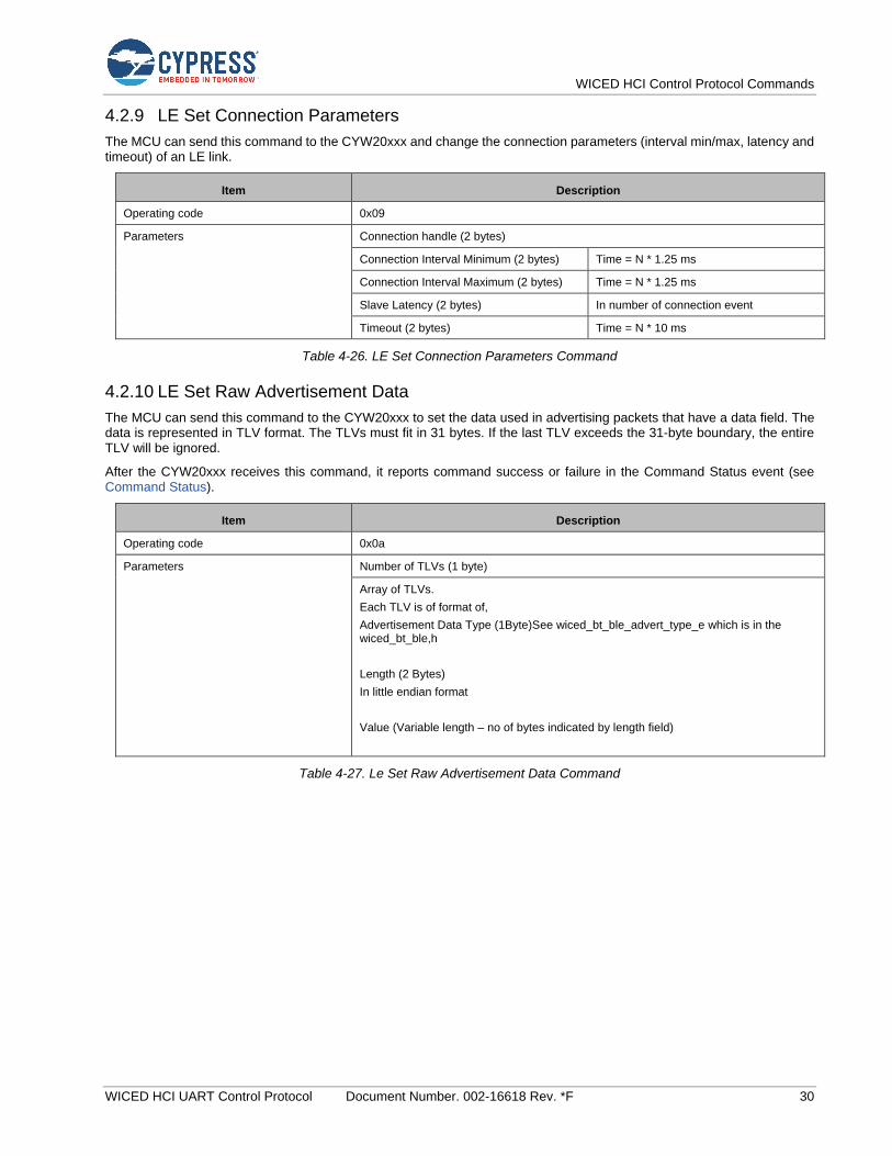
WICED HCI Control Protocol Commands
WICED HCI UART Control Protocol Document Number. 002-16618 Rev. *F 30
4.2.9 LE Set Connection Parameters
The MCU can send this command to the CYW20xxx and change the connection parameters (interval min/max, latency and timeout) of an LE link.
Item Description
Operating code 0x09
Parameters Connection handle (2 bytes)
Connection Interval Minimum (2 bytes) Time = N * 1.25 ms
Connection Interval Maximum (2 bytes) Time = N * 1.25 ms
Slave Latency (2 bytes) In number of connection event
Timeout (2 bytes) Time = N * 10 ms
Table 4-26. LE Set Connection Parameters Command
4.2.10 LE Set Raw Advertisement Data
The MCU can send this command to the CYW20xxx to set the data used in advertising packets that have a data field. The data is represented in TLV format. The TLVs must fit in 31 bytes. If the last TLV exceeds the 31-byte boundary, the entire TLV will be ignored.
After the CYW20xxx receives this command, it reports command success or failure in the Command Status event (see Command Status).
Item Description
Operating code 0x0a
Parameters Number of TLVs (1 byte)
Array of TLVs.
Each TLV is of format of,
Advertisement Data Type (1Byte)See wiced_bt_ble_advert_type_e which is in the wiced_bt_ble,h
Length (2 Bytes)
In little endian format
Value (Variable length – no of bytes indicated by length field)
Table 4-27. Le Set Raw Advertisement Data Command
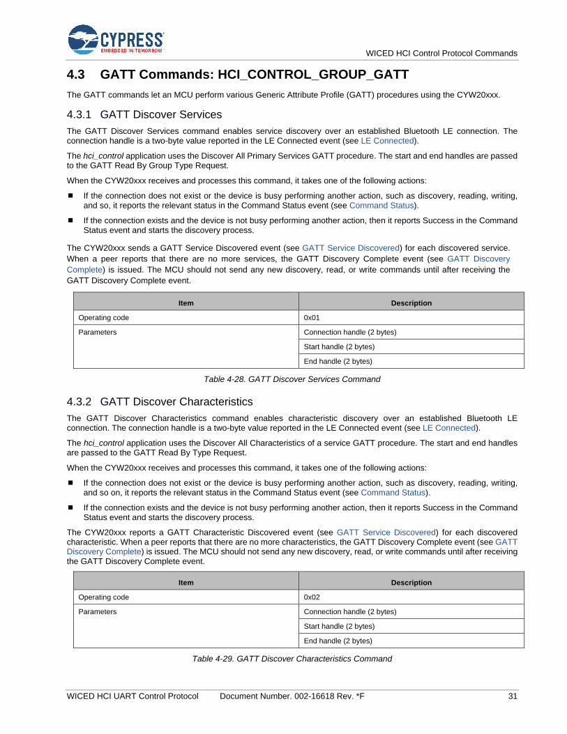
WICED HCI Control Protocol Commands
WICED HCI UART Control Protocol Document Number. 002-16618 Rev. *F 31
4.3 GATT Commands: HCI_CONTROL_GROUP_GATT
The GATT commands let an MCU perform various Generic Attribute Profile (GATT) procedures using the CYW20xxx.
4.3.1 GATT Discover Services
The GATT Discover Services command enables service discovery over an established Bluetooth LE connection. The connection handle is a two-byte value reported in the LE Connected event (see LE Connected).
The hci_control application uses the Discover All Primary Services GATT procedure. The start and end handles are passed to the GATT Read By Group Type Request.
When the CYW20xxx receives and processes this command, it takes one of the following actions:
If the connection does not exist or the device is busy performing another action, such as discovery, reading, writing, and so, it reports the relevant status in the Command Status event (see Command Status).
If the connection exists and the device is not busy performing another action, then it reports Success in the Command Status event and starts the discovery process.
The CYW20xxx sends a GATT Service Discovered event (see GATT Service Discovered) for each discovered service.
When a peer reports that there are no more services, the GATT Discovery Complete event (see GATT Discovery
Complete) is issued. The MCU should not send any new discovery, read, or write commands until after receiving the
GATT Discovery Complete event.
Item Description
Operating code 0x01
Parameters Connection handle (2 bytes)
Start handle (2 bytes)
End handle (2 bytes)
Table 4-28. GATT Discover Services Command
4.3.2 GATT Discover Characteristics
The GATT Discover Characteristics command enables characteristic discovery over an established Bluetooth LE connection. The connection handle is a two-byte value reported in the LE Connected event (see LE Connected).
The hci_control application uses the Discover All Characteristics of a service GATT procedure. The start and end handles are passed to the GATT Read By Type Request.
When the CYW20xxx receives and processes this command, it takes one of the following actions:
If the connection does not exist or the device is busy performing another action, such as discovery, reading, writing, and so on, it reports the relevant status in the Command Status event (see Command Status).
If the connection exists and the device is not busy performing another action, then it reports Success in the Command Status event and starts the discovery process.
The CYW20xxx reports a GATT Characteristic Discovered event (see GATT Service Discovered) for each discovered characteristic. When a peer reports that there are no more characteristics, the GATT Discovery Complete event (see GATT Discovery Complete) is issued. The MCU should not send any new discovery, read, or write commands until after receiving the GATT Discovery Complete event.
Item Description
Operating code 0x02
Parameters Connection handle (2 bytes)
Start handle (2 bytes)
End handle (2 bytes)
Table 4-29. GATT Discover Characteristics Command
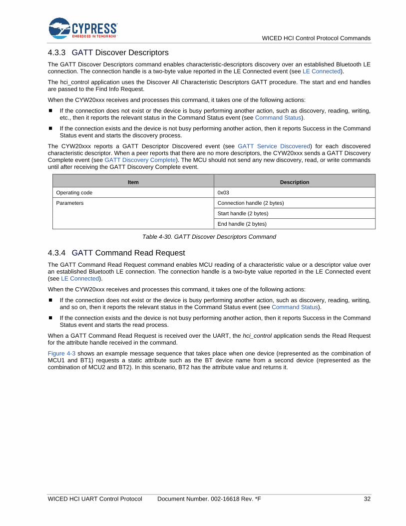
WICED HCI Control Protocol Commands
WICED HCI UART Control Protocol Document Number. 002-16618 Rev. *F 32
4.3.3 GATT Discover Descriptors
The GATT Discover Descriptors command enables characteristic-descriptors discovery over an established Bluetooth LE connection. The connection handle is a two-byte value reported in the LE Connected event (see LE Connected).
The hci_control application uses the Discover All Characteristic Descriptors GATT procedure. The start and end handles are passed to the Find Info Request.
When the CYW20xxx receives and processes this command, it takes one of the following actions:
If the connection does not exist or the device is busy performing another action, such as discovery, reading, writing, etc., then it reports the relevant status in the Command Status event (see Command Status).
If the connection exists and the device is not busy performing another action, then it reports Success in the Command Status event and starts the discovery process.
The CYW20xxx reports a GATT Descriptor Discovered event (see GATT Service Discovered) for each discovered characteristic descriptor. When a peer reports that there are no more descriptors, the CYW20xxx sends a GATT Discovery Complete event (see GATT Discovery Complete). The MCU should not send any new discovery, read, or write commands until after receiving the GATT Discovery Complete event.
Item Description
Operating code 0x03
Parameters Connection handle (2 bytes)
Start handle (2 bytes)
End handle (2 bytes)
Table 4-30. GATT Discover Descriptors Command
4.3.4 GATT Command Read Request
The GATT Command Read Request command enables MCU reading of a characteristic value or a descriptor value over an established Bluetooth LE connection. The connection handle is a two-byte value reported in the LE Connected event (see LE Connected).
When the CYW20xxx receives and processes this command, it takes one of the following actions:
If the connection does not exist or the device is busy performing another action, such as discovery, reading, writing, and so on, then it reports the relevant status in the Command Status event (see Command Status).
If the connection exists and the device is not busy performing another action, then it reports Success in the Command Status event and starts the read process.
When a GATT Command Read Request is received over the UART, the hci_control application sends the Read Request for the attribute handle received in the command.
Figure 4-3 shows an example message sequence that takes place when one device (represented as the combination of MCU1 and BT1) requests a static attribute such as the BT device name from a second device (represented as the combination of MCU2 and BT2). In this scenario, BT2 has the attribute value and returns it.
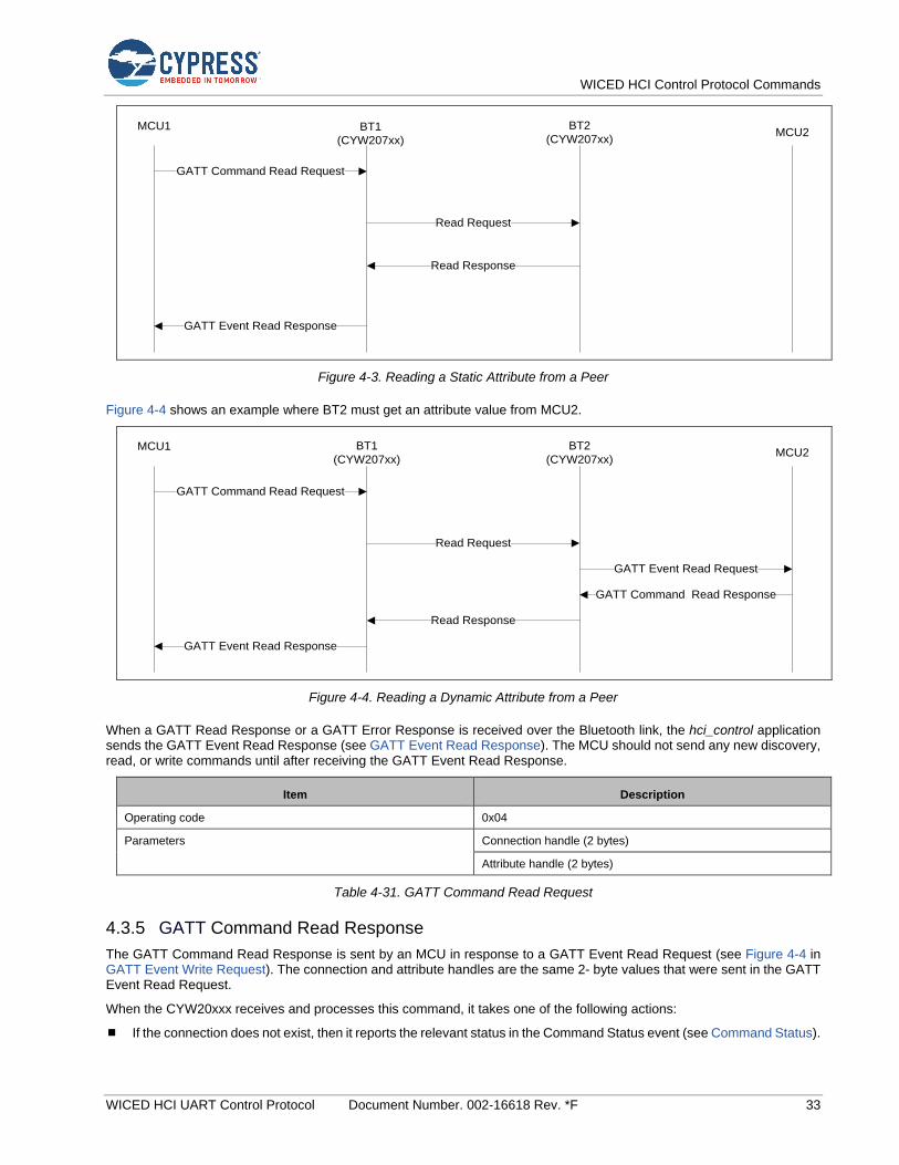
WICED HCI Control Protocol Commands
WICED HCI UART Control Protocol Document Number. 002-16618 Rev. *F 33
GATT Command Read Request
GATT Event Read Response
Read Request
Read Response
MCU1 BT2
(CYW207xx)MCU2
BT1
(CYW207xx)
Figure 4-3. Reading a Static Attribute from a Peer
Figure 4-4 shows an example where BT2 must get an attribute value from MCU2.
GATT Command Read Request
GATT Event Read Response
Read Request
Read Response
MCU1 BT1
(CYW207xx)
BT2
(CYW207xx)MCU2
GATT Event Read Request
GATT Command Read Response
Figure 4-4. Reading a Dynamic Attribute from a Peer
When a GATT Read Response or a GATT Error Response is received over the Bluetooth link, the hci_control application sends the GATT Event Read Response (see GATT Event Read Response). The MCU should not send any new discovery, read, or write commands until after receiving the GATT Event Read Response.
Item Description
Operating code 0x04
Parameters Connection handle (2 bytes)
Attribute handle (2 bytes)
Table 4-31. GATT Command Read Request
4.3.5 GATT Command Read Response
The GATT Command Read Response is sent by an MCU in response to a GATT Event Read Request (see Figure 4-4 in GATT Event Write Request). The connection and attribute handles are the same 2- byte values that were sent in the GATT Event Read Request.
When the CYW20xxx receives and processes this command, it takes one of the following actions:
If the connection does not exist, then it reports the relevant status in the Command Status event (see Command Status).
WICED HCI Control Protocol Commands
WICED HCI UART Control Protocol Document Number. 002-16618 Rev. *F 34
If the connection exists, then it reports Success in the Command Status event and sends the response to the connected Bluetooth device.
Item Description
Operating code 0x05
Parameters Connection handle (2 bytes)
Attribute handle (2 bytes)
Read Status (1 byte)
Data (variable bytes)
Table 4-32. GATT Command Read Response
4.3.6 GATT Command Write
The GATT Command Write command enables MCU scheduling of transmissions over an established Bluetooth LE connection. The connection handle is a two-byte value reported in the LE Connected event (see LE Connected).
When the CYW20xxx receives and processes this command, it takes one of the following actions:
If the connection does not exist or the device is busy performing another action, such as discovery, reading, writing, etc., then it reports the relevant status in the Command Status event (see Command Status).
If the connection exists and the device is not busy performing another action, then it reports Success in the Command Status event and starts the write process.
The CYW20xxx has a limited number of transmit buffers. If the hci_control application is able to allocate a buffer and schedule it for transmission, then the write operation is considered complete and the hci_control application sends the GATT Event Write Response (see GATT Event Write Response). If all transmit buffers are already allocated and, thus, unavailable, then the hci_control application saves the data received in the command and delays sending the GATT Event Write Response until a transmit buffer becomes available and the data gets scheduled for transmission. The MCU should not send any new discovery, read, or write commands until after receiving the GATT Event Write Response.
Item Description
Operating code 0x06
Parameters Connection handle (2 bytes)
Attribute handle (2 bytes)
Data (variable bytes)
Table 4-33. GATT Command Write Command
Figure 4-5 shows an example GATT Command Write message sequence.
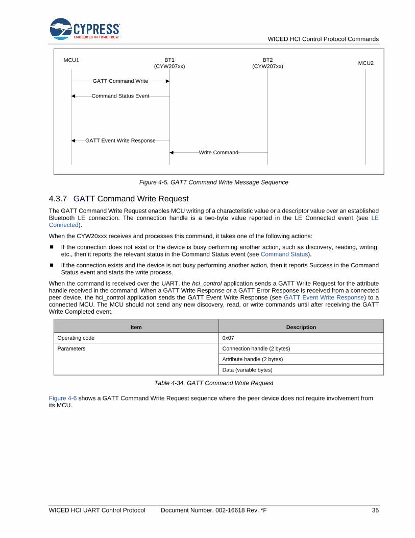
WICED HCI Control Protocol Commands
WICED HCI UART Control Protocol Document Number. 002-16618 Rev. *F 35
GATT Command Write
GATT Event Write Response
Write Command
MCU1 BT1
(CYW207xx)
BT2
(CYW207xx)MCU2
Command Status Event
Figure 4-5. GATT Command Write Message Sequence
4.3.7 GATT Command Write Request
The GATT Command Write Request enables MCU writing of a characteristic value or a descriptor value over an established Bluetooth LE connection. The connection handle is a two-byte value reported in the LE Connected event (see LE Connected).
When the CYW20xxx receives and processes this command, it takes one of the following actions:
If the connection does not exist or the device is busy performing another action, such as discovery, reading, writing, etc., then it reports the relevant status in the Command Status event (see Command Status).
If the connection exists and the device is not busy performing another action, then it reports Success in the Command Status event and starts the write process.
When the command is received over the UART, the hci_control application sends a GATT Write Request for the attribute handle received in the command. When a GATT Write Response or a GATT Error Response is received from a connected peer device, the hci_control application sends the GATT Event Write Response (see GATT Event Write Response) to a connected MCU. The MCU should not send any new discovery, read, or write commands until after receiving the GATT Write Completed event.
Item Description
Operating code 0x07
Parameters Connection handle (2 bytes)
Attribute handle (2 bytes)
Data (variable bytes)
Table 4-34. GATT Command Write Request
Figure 4-6 shows a GATT Command Write Request sequence where the peer device does not require involvement from its MCU.
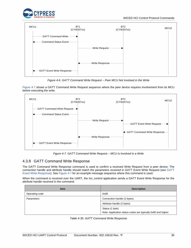
WICED HCI Control Protocol Commands
WICED HCI UART Control Protocol Document Number. 002-16618 Rev. *F 36
GATT Command Write
GATT Event Write Response
Write Response
MCU1 BT1
(CYW207xx)
BT2
(CYW207xx)MCU2
Command Status Event
Write Request
Figure 4-6. GATT Command Write Request – Peer MCU Not Involved in the Write
Figure 4-7 shows a GATT Command Write Request sequence where the peer device requires involvement from its MCU before executing the write.
GATT Command Write Request
GATT Event Write Response
Write Response
MCU1 BT1
(CYW207xx)
BT2
(CYW207xx)MCU2
Command Status Event
Write Request
GATT Command Write Response
GATT Event Write Request
Figure 4-7. GATT Command Write Request – MCU Is Involved in a Write
4.3.8 GATT Command Write Response
The GATT Command Write Response command is used to confirm a received Write Request from a peer device. The connection handle and attribute handle should match the parameters received in GATT Event Write Request (see GATT Event Write Response). See Figure 4-7 for an example message sequence where this command is used.
When the command is received over the UART, the hci_control application sends a GATT Event Write Response for the attribute handle received in the command.
Item Description
Operating code 0x08
Parameters Connection handle (2 bytes)
Attribute handle (2 bytes)
Status (1 byte)
Note: Application status codes are typically 0x80 and higher.
Table 4-35. GATT Command Write Response
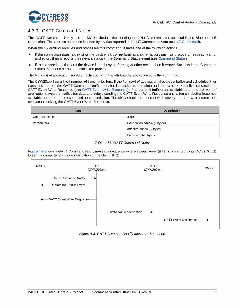
WICED HCI Control Protocol Commands
WICED HCI UART Control Protocol Document Number. 002-16618 Rev. *F 37
4.3.9 GATT Command Notify
The GATT Command Notify lets an MCU schedule the sending of a Notify packet over an established Bluetooth LE connection. The connection handle is a two-byte value reported in the LE Connected event (see LE Connected).
When the CYW20xxx receives and processes this command, it takes one of the following actions:
If the connection does not exist or the device is busy performing another action, such as discovery, reading, writing, and so on, then it reports the relevant status in the Command Status event (see Command Status).
If the connection exists and the device is not busy performing another action, then it reports Success in the Command Status event and starts the notification process.
The hci_control application sends a notification with the attribute handle received in the command.
The CYW20xxx has a fixed number of transmit buffers. If the hci_control application allocates a buffer and schedules it for transmission, then the GATT Command Notify operation is considered complete and the hci_control application sends the GATT Event Write Response (see GATT Event Write Response). If no transmit buffers are available, then the hci_control application saves the notification data and delays sending the GATT Event Write Response until a transmit buffer becomes available and the data is scheduled for transmission. The MCU should not send new discovery, read, or write commands until after receiving the GATT Event Write Response.
Item Description
Operating code 0x09
Parameters Connection handle (2 bytes)
Attribute handle (2 bytes)
Data (variable bytes)
Table 4-36. GATT Command Notify
Figure 4-8 shows a GATT Command Notify message sequence where a peer server (BT1) is prompted by its MCU (MCU1) to send a characteristic value notification to the client (BT2).
GATT Command Notify
GATT Event Write Response
MCU1 BT1
(CYW207xx)
BT2
(CYW207xx)MCU2
Command Status Event
Handle Value Notification
GATT Event Notification
Figure 4-8. GATT Command Notify Message Sequence
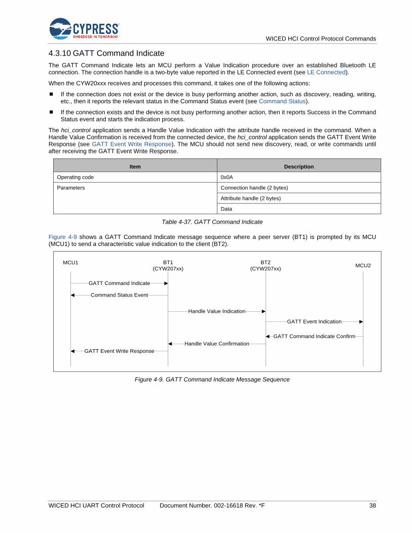
WICED HCI Control Protocol Commands
WICED HCI UART Control Protocol Document Number. 002-16618 Rev. *F 38
4.3.10 GATT Command Indicate
The GATT Command Indicate lets an MCU perform a Value Indication procedure over an established Bluetooth LE connection. The connection handle is a two-byte value reported in the LE Connected event (see LE Connected).
When the CYW20xxx receives and processes this command, it takes one of the following actions:
If the connection does not exist or the device is busy performing another action, such as discovery, reading, writing, etc., then it reports the relevant status in the Command Status event (see Command Status).
If the connection exists and the device is not busy performing another action, then it reports Success in the Command Status event and starts the indication process.
The hci_control application sends a Handle Value Indication with the attribute handle received in the command. When a Handle Value Confirmation is received from the connected device, the hci_control application sends the GATT Event Write Response (see GATT Event Write Response). The MCU should not send new discovery, read, or write commands until after receiving the GATT Event Write Response.
Item Description
Operating code 0x0A
Parameters Connection handle (2 bytes)
Attribute handle (2 bytes)
Data
Table 4-37. GATT Command Indicate
Figure 4-9 shows a GATT Command Indicate message sequence where a peer server (BT1) is prompted by its MCU (MCU1) to send a characteristic value indication to the client (BT2).
GATT Command Indicate
GATT Event Write Response
MCU1 BT1
(CYW207xx)
BT2
(CYW207xx)MCU2
Command Status Event
Handle Value Indication
Handle Value Confirmation
GATT Event Indication
GATT Command Indicate Confirm
Figure 4-9. GATT Command Indicate Message Sequence
WICED HCI Control Protocol Commands
WICED HCI UART Control Protocol Document Number. 002-16618 Rev. *F 39
4.3.11 GATT Command Indicate Confirm
The GATT Command Indicate Confirm lets an MCU send a confirmation to an indication received from a peer device. The connection handle and attribute handle should match the parameters received in the GATT Event Indicate event (see GATT Event Indication).
When the command is received over the UART, the hci_control application sends a Handle Value Confirmation (see Figure 4-9) for the attribute handle received in the command.
Item Description
Operating code 0x0B
Parameters Connection handle (2 bytes)
Attribute handle (2 bytes)
Table 4-38. GATT Command Indicate Confirm
4.3.12 GATT DB Add Primary Service
The Add Primary Service Command instructs the GATT DB App on CYW2070xx to Add a desired Primary Service into the GATT Database.
Item Description
Operating code 0x0C
Parameters Service handle (2 bytes)
UUID (16/128 bits)
Table 4-39. GATT DB Add Primary Service
4.3.13 GATT DB Add Secondary Service
The Add Secondary Service Command instructs the GATT DB App on CYW2070xx to Add a desired Secondary Service into the GATT Database.
Item Description
Operating code 0x0D
Parameters Service handle (2 bytes)
UUID (16/128 bits)
Table 4-40. GATT DB Add Secondary Service
4.3.14 GATT DB Add Included Service
The Add Included Service Command instructs the GATT DB App on CYW2070xx to Add a desired Included Service into the GATT Database.
Item Description
Operating code 0x0E
Parameters Included Service handle (2 bytes)
Service Handle (2 bytes)
End Group (2 bytes)
Table 4-41. GATT DB Add Included Service

WICED HCI Control Protocol Commands
WICED HCI UART Control Protocol Document Number. 002-16618 Rev. *F 40
4.3.15 GATT DB Add Characteristic
The Add Characteristic Command instructs the GATT DB App on CYW2070xx to Add Characteristic into the GATT Database.
Item Description
Operating code 0x0F
Parameters Service handle (2 bytes)
Handle Value (2 bytes)
Property (2 bytes)
Permission (2 bytes)
Table 4-42. GATT DB Add Characteristic
4.3.16 GATT DB Add Descriptor
The Add Descriptor Command instructs the GATT DB App on CYW2070xx to Add Descriptor into the GATT Database.
Item Description
Operating code 0x10
Parameters Handle (2 bytes)
Permission (1 byte)
Table 4-42. GATT DB Add Descriptor
4.4 Hands-Free Commands— HCI_CONTROL_GROUP_HF
The Hands-Free (HF) commands let an MCU perform various HF procedures using the CYW20xxx.
4.4.1 HF Connect
The HF Connect command instructs the CYW20xxx to try establishing a connection to a specified Audio Gateway (AG), which is typically a phone.
When a connection is established, the CYW20xxx sends an HF Open event. The status field of that event tells whether the connection could be established or not.
Item Description
Operating code 0x01
Parameters AG Bluetooth device address (6 bytes)
Table 4-39. HF Connect Command
When the CYW20xxx receives and processes this command, it:
Allocates a handle for the connection.
Starts paging the AG using the passed-in address.
Establishes the Hands-free Profile-defined Service Level Connection (SLC) if the connection is created.
Sends an HF Open event with the connection assigned handle and success/failure status.
Sends an HF Connected event if the SLC gets established.

WICED HCI Control Protocol Commands
WICED HCI UART Control Protocol Document Number. 002-16618 Rev. *F 41
4.4.2 HF Disconnect
The HF Disconnect command instructs the CYW20xxx to remove an existing connection to an AG.
Item Description
Operating code 0x02
Parameters Connection handle (2 bytes)
Table 4-40. HF Disconnect Command
When the CYW20xxx receives and processes this command, it disconnects the connection identified by the passed handle. When the connection is disconnected, it sends an HF Closed event.
4.4.3 HF Open Audio
The HF Open Audio command instructs the CYW20xxx to create an audio connection on the AG identified by the connection handle.
Item Description
Operating code 0x03
Parameters Connection handle (2 bytes)
Table 4-41. HF Open Audio Command
When the CYW20xxx receives and processes this command, it attempts to open an audio connection on the AG identified by the passed connection handle. When an audio connection is established, it sends an HF Audio Open event.
4.4.4 HF Close Audio
The HF Close Audio command instructs the CYW20xxx to close the audio connection on the AG identified by the connection handle.
Item Description
Operating code 0x04
Parameters Connection handle (2 bytes)
Table 4-42. HF Close Audio Command
When the CYW20xxx receives and processes this command, it attempts to close an audio connection on the AG identified by the passed handle connection. When the audio connection is closed, it sends an HF Audio Close event.
4.4.5 HF Accept/Reject Audio Connection
The HF Accept/Reject Audio Connection command instructs the CYW20xxx to accept/reject the SCO connection
request on the AG identified by SCO index.
Item Description
Operating code 0x05
Parameters SCO index (2 bytes)
Flag (1 byte) 0: Reject Audio Connection Request
1: Accept Audio Connection Request
Table 4-43. HF Accept/Reject Audio Connection Command
When the CYW20xxx receives and processes this command, it attempts to accept/reject the SCO connection on the AG identified by the passed handle connection.
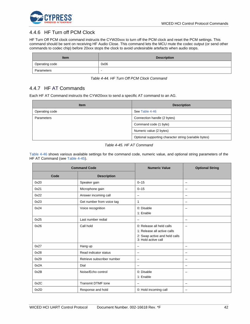
WICED HCI Control Protocol Commands
WICED HCI UART Control Protocol Document Number. 002-16618 Rev. *F 42
4.4.6 HF Turn off PCM Clock
HF Turn Off PCM clock command instructs the CYW20xxx to turn off the PCM clock and reset the PCM settings. This command should be sent on receiving HF Audio Close. This command lets the MCU mute the codec output (or send other commands to codec chip) before 20xxx stops the clock to avoid undesirable artefacts when audio stops.
Item Description
Operating code 0x06
Parameters -
Table 4-44. HF Turn Off PCM Clock Command
4.4.7 HF AT Commands
Each HF AT Command instructs the CYW20xxx to send a specific AT command to an AG.
Item Description
Operating code See Table 4-46
Parameters Connection handle (2 bytes)
Command code (1 byte)
Numeric value (2 bytes)
Optional supporting character string (variable bytes)
Table 4-45. HF AT Command
Table 4-46 shows various available settings for the command code, numeric value, and optional string parameters of the HF AT Command (see Table 4-45).
Command Code Numeric Value Optional String
Code Description
0x20 Speaker gain 0–15 –
0x21 Microphone gain 0–15 –
0x22 Answer incoming call – –
0x23 Get number from voice tag 1 –
0x24 Voice recognition 0: Disable
1: Enable
–
0x25 Last number redial – –
0x26 Call hold 0: Release all held calls
1: Release all active calls
2: Swap active and held calls 3: Hold active call
–
0x27 Hang up – –
0x28 Read indicator status – –
0x29 Retrieve subscriber number – –
0x2A Dial – –
0x2B Noise/Echo control 0: Disable
1: Enable
–
0x2C Transmit DTMF tone – –
0x2D Response and hold 0: Hold incoming call –

WICED HCI Control Protocol Commands
WICED HCI UART Control Protocol Document Number. 002-16618 Rev. *F 43
Command Code Numeric Value Optional String
Code Description
1: Accept held incoming call
2: Reject held incoming call
0x2E Get operator information - –
0x2F Extended result codes 1: Enable –
0x30 Get current call list – –
0x31 Indicator control – –
0x32 Send HF indicator – –
0x33 Send proprietary AT command – –
Table 4-46. HF AT Command Parameters
When the CYW20xxx receives and processes this command, it attempts to send the corresponding AT command to the AG identified by the connection handle. When a response is received from the AG, it is sent back via an HF Response event (see HF Response). Another command should not be sent until after the response event is received.
4.5 Serial Port Profile Commands—HCI_CONTROL_GROUP_SPP
The Serial Port Profile (SPP) commands let an MCU establish an SPP connection to a peer and send data.
4.5.1 SPP Connect
The MCU can send an SPP Connect command to the CYW20xxx to establish an SPP connection to a specified device. Upon receiving the command, the CYW20xxx establishes an ACL data connection, performs a Service Discovery Protocol (SDP) search for the RFCOMM service, and establishes an RFCOMM connection to that service.
If the operation is successful, the CYW20xxx will send the SPP Connected event back to the MCU. If the operation fails, the SPP Connection Failed or SPP Service Not Found event is sent.
Item Description
Operating code 0x01
Parameters Bluetooth device address of the peer device (6 bytes)
Table 4-47. SPP Connect Command
4.5.2 SPP Disconnect
The MCU can send an SPP Disconnect command to disconnect a previously established SPP connection.
Item Description
Operating code 0x02
Parameters Connection handle (2 bytes)
The connection handle as reported in the SPP Connected event.
Table 4-48. SPP Disconnect Command
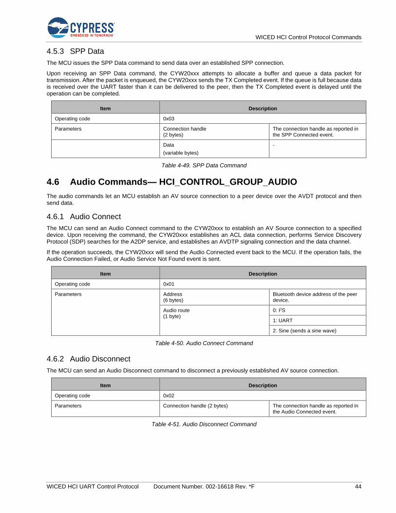
WICED HCI Control Protocol Commands
WICED HCI UART Control Protocol Document Number. 002-16618 Rev. *F 44
4.5.3 SPP Data
The MCU issues the SPP Data command to send data over an established SPP connection.
Upon receiving an SPP Data command, the CYW20xxx attempts to allocate a buffer and queue a data packet for transmission. After the packet is enqueued, the CYW20xxx sends the TX Completed event. If the queue is full because data is received over the UART faster than it can be delivered to the peer, then the TX Completed event is delayed until the operation can be completed.
Item Description
Operating code 0x03
Parameters Connection handle (2 bytes)
The connection handle as reported in the SPP Connected event.
Data
(variable bytes)
-
Table 4-49. SPP Data Command
4.6 Audio Commands— HCI_CONTROL_GROUP_AUDIO
The audio commands let an MCU establish an AV source connection to a peer device over the AVDT protocol and then send data.
4.6.1 Audio Connect
The MCU can send an Audio Connect command to the CYW20xxx to establish an AV Source connection to a specified device. Upon receiving the command, the CYW20xxx establishes an ACL data connection, performs Service Discovery Protocol (SDP) searches for the A2DP service, and establishes an AVDTP signaling connection and the data channel.
If the operation succeeds, the CYW20xxx will send the Audio Connected event back to the MCU. If the operation fails, the Audio Connection Failed, or Audio Service Not Found event is sent.
Item Description
Operating code 0x01
Parameters Address (6 bytes)
Bluetooth device address of the peer device.
Audio route (1 byte)
0: I2S
1: UART
2: Sine (sends a sine wave)
Table 4-50. Audio Connect Command
4.6.2 Audio Disconnect
The MCU can send an Audio Disconnect command to disconnect a previously established AV source connection.
Item Description
Operating code 0x02
Parameters Connection handle (2 bytes) The connection handle as reported in the Audio Connected event.
Table 4-51. Audio Disconnect Command
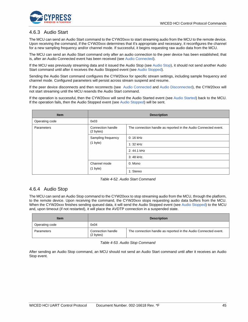
WICED HCI Control Protocol Commands
WICED HCI UART Control Protocol Document Number. 002-16618 Rev. *F 45
4.6.3 Audio Start
The MCU can send an Audio Start command to the CYW20xxx to start streaming audio from the MCU to the remote device. Upon receiving the command, if the CYW20xxx determines that it’s appropriate and necessary, it reconfigures the channel for a new sampling frequency and/or channel mode. If successful, it begins requesting raw audio data from the MCU.
The MCU can send an Audio Start command only after an audio connection to the peer device has been established; that is, after an Audio Connected event has been received (see Audio Connected).
If the MCU was previously streaming data and it issued the Audio Stop (see Audio Stop), it should not send another Audio Start command until after it receives the Audio Stopped event (see Audio Stopped).
Sending the Audio Start command configures the CYW20xxx for specific stream settings, including sample frequency and channel mode. Configured parameters will persist across stream suspend and resume.
If the peer device disconnects and then reconnects (see Audio Connected and Audio Disconnected), the CYW20xxx will not start streaming until the MCU resends the Audio Start command.
If the operation is successful, then the CYW20xxx will send the Audio Started event (see Audio Started) back to the MCU.
If the operation fails, then the Audio Stopped event (see Audio Stopped) will be sent.
Item Description
Operating code 0x03
Parameters Connection handle (2 bytes)
The connection handle as reported in the Audio Connected event.
Sampling frequency
(1 byte)
0: 16 kHz
1: 32 kHz
2: 44.1 kHz
3: 48 kHz.
Channel mode
(1 byte)
0: Mono
1: Stereo
Table 4-52. Audio Start Command
4.6.4 Audio Stop
The MCU can send an Audio Stop command to the CYW20xxx to stop streaming audio from the MCU, through the platform, to the remote device. Upon receiving the command, the CYW20xxx stops requesting audio data buffers from the MCU. When the CYW20xxx finishes sending queued data, it will send the Audio Stopped event (see Audio Stopped) to the MCU and, upon timeout (if not restarted), it will place the AVDTP connection in a suspended state.
Item Description
Operating code 0x04
Parameters Connection handle (2 bytes)
The connection handle as reported in the Audio Connected event.
Table 4-53. Audio Stop Command
After sending an Audio Stop command, an MCU should not send an Audio Start command until after it receives an Audio Stop event.
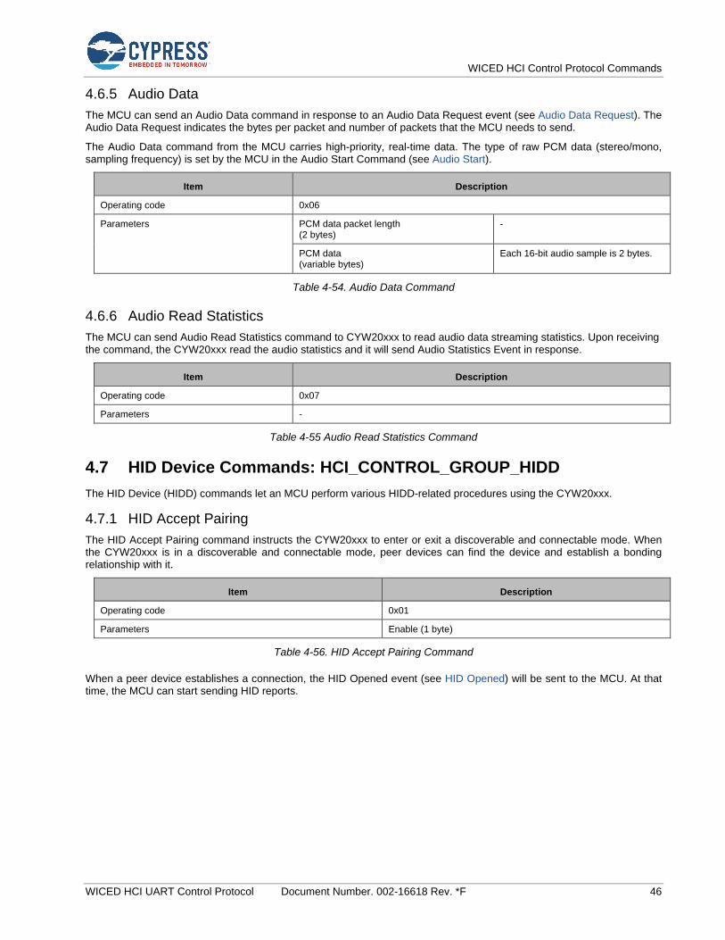
WICED HCI Control Protocol Commands
WICED HCI UART Control Protocol Document Number. 002-16618 Rev. *F 46
4.6.5 Audio Data
The MCU can send an Audio Data command in response to an Audio Data Request event (see Audio Data Request). The Audio Data Request indicates the bytes per packet and number of packets that the MCU needs to send.
The Audio Data command from the MCU carries high-priority, real-time data. The type of raw PCM data (stereo/mono, sampling frequency) is set by the MCU in the Audio Start Command (see Audio Start).
Item Description
Operating code 0x06
Parameters PCM data packet length (2 bytes)
-
PCM data (variable bytes)
Each 16-bit audio sample is 2 bytes.
Table 4-54. Audio Data Command
4.6.6 Audio Read Statistics
The MCU can send Audio Read Statistics command to CYW20xxx to read audio data streaming statistics. Upon receiving the command, the CYW20xxx read the audio statistics and it will send Audio Statistics Event in response.
Item Description
Operating code 0x07
Parameters -
Table 4-55 Audio Read Statistics Command
4.7 HID Device Commands: HCI_CONTROL_GROUP_HIDD
The HID Device (HIDD) commands let an MCU perform various HIDD-related procedures using the CYW20xxx.
4.7.1 HID Accept Pairing
The HID Accept Pairing command instructs the CYW20xxx to enter or exit a discoverable and connectable mode. When the CYW20xxx is in a discoverable and connectable mode, peer devices can find the device and establish a bonding relationship with it.
Item Description
Operating code 0x01
Parameters Enable (1 byte)
Table 4-56. HID Accept Pairing Command
When a peer device establishes a connection, the HID Opened event (see HID Opened) will be sent to the MCU. At that time, the MCU can start sending HID reports.
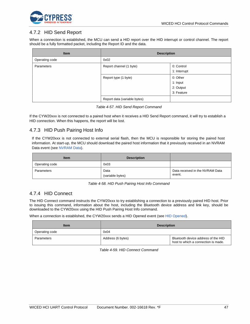
WICED HCI Control Protocol Commands
WICED HCI UART Control Protocol Document Number. 002-16618 Rev. *F 47
4.7.2 HID Send Report
When a connection is established, the MCU can send a HID report over the HID interrupt or control channel. The report should be a fully formatted packet, including the Report ID and the data.
Item Description
Operating code 0x02
Parameters Report channel (1 byte) 0: Control
1: Interrupt
Report type (1 byte) 0: Other
1: Input
2: Output
3: Feature
Report data (variable bytes)
Table 4-57. HID Send Report Command
If the CYW20xxx is not connected to a paired host when it receives a HID Send Report command, it will try to establish a
HID connection. When this happens, the report will be lost.
4.7.3 HID Push Pairing Host Info
If the CYW20xxx is not connected to external serial flash, then the MCU is responsible for storing the paired host
information. At start-up, the MCU should download the paired host information that it previously received in an NVRAM
Data event (see NVRAM Data).
Item Description
Operating code 0x03
Parameters Data
(variable bytes)
Data received in the NVRAM Data event.
Table 4-58. HID Push Pairing Host Info Command
4.7.4 HID Connect
The HID Connect command instructs the CYW20xxx to try establishing a connection to a previously paired HID host. Prior to issuing this command, information about the host, including the Bluetooth device address and link key, should be downloaded to the CYW20xxx using the HID Push Pairing Host Info command.
When a connection is established, the CYW20xxx sends a HID Opened event (see HID Opened).
Item Description
Operating code 0x04
Parameters Address (6 bytes) Bluetooth device address of the HID host to which a connection is made.
Table 4-59. HID Connect Command

WICED HCI Control Protocol Commands
WICED HCI UART Control Protocol Document Number. 002-16618 Rev. *F 48
4.8 AV Remote Control Target Commands: HCI_CONTROL_GROUP_AVRC_TARGET
4.8.1 AVRC Target Connect
Note: This command should only be used in the case of PTS testing. Target side connections are made in conjunction with the Audio Source connections.
The MCU can send this to the CYW20xxx to establish an AV remote control target connection to a specified device. Upon receiving this command, the CYW20xxx establishes an ACL data connection if one does not exist yet, performs the Service Discovery Protocol (SDP), searches for the AVRC service, and establishes an AVCTP channel.
If the operation succeeds, the CYW20xxx sends the AVRC Connected event (see AVRC Controller Connected) back to the MCU. If the operation fails, the CYW20xxx sends the AVRC Disconnected event (see AVRC Controller Disconnected).
Item Description
Operating code 0x01
Parameters bd_addr (6 bytes) Bluetooth address of the peer device.
Table 4-60. AVRC Target Connect Command
4.8.2 AVRC Target Disconnect
Note: This command should only be used in the case of PTS testing. Target side connections are made in conjunction with the Audio Source connections.
The MCU can send this command to disconnect a previously established AV remote control connection.
Item Description
Operating code 0x02
Parameters -
Table 4-61. AVRC Target Disconnect Command

WICED HCI Control Protocol Commands
WICED HCI UART Control Protocol Document Number. 002-16618 Rev. *F 49
4.8.3 AVRC Target Track Information
The MCU can send this command to the CYW20xxx to inform it of updates to the track information for the currently playing track. The MCU shall send information about all changed attributes in a single command. The command can include all attributes or it can be limited to one or several attributes. For example, one could send Title and Track Number if only those attributes have changed. If an attribute is not available for the new track, the MCU should include the attribute with length of zero.
Item Description
Operating code 0x05
Parameters Attribute Id of the first attribute (1 byte) 1: Title
2: Artist
3: Album
4: Track number
5: Number of tracks
6: Genre
7: Playing time
Attribute Length of the first attribute (1 byte) Attribute string length
Attribute Value of the first attribute (n bytes as defined above)
Attribute value expressed as a character string.
Attribute Id of the second attribute (1 byte) (see list above)
Attribute Length of the second attribute (1 byte)
Attribute string length
Attribute Value of the second attribute (n bytes as defined above)
Attribute value expressed as a character string.
… (up to 7 entries) …
Table 4-62. AVRC Target Track Information Command
4.8.4 AVRC Target Player Status
The MCU can send this command to the CYW20xxx with the player play state and track position information. It is mandatory for the MCU to send this status update for every change in the playback status of the local player If last reported status is playing, the CYW20xxx will assume that the track position on the player is continuously updating 1000 ms every second. The MCU must send the Track Position only if changes are not due to the standard playback. For example, the command needs to be sent regularly if the player is performing fast forward or rewind operations, or if the position jumps due to the local update on the player.
Item Description
Operating code 0x06
Parameters Play State 0x00: STOPPED
0x01: PLAYING
0x02: PAUSED
0x03: FWD_SEEK
0x04: REV_SEEK
Track Length (4 bytes) Length of the current track in milliseconds
Track Position (4 bytes) Position in the current track in ms within Track Length defined above.
Table 4-63. AVRC Target Player Status Command
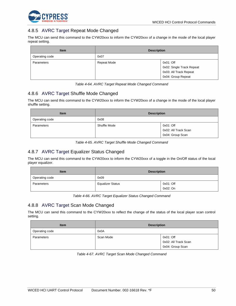
WICED HCI Control Protocol Commands
WICED HCI UART Control Protocol Document Number. 002-16618 Rev. *F 50
4.8.5 AVRC Target Repeat Mode Changed
The MCU can send this command to the CYW20xxx to inform the CYW20xxx of a change in the mode of the local player repeat setting.
Item Description
Operating code 0x07
Parameters Repeat Mode 0x01: Off
0x02: Single Track Repeat
0x03: All Track Repeat
0x04: Group Repeat
Table 4-64. AVRC Target Repeat Mode Changed Command
4.8.6 AVRC Target Shuffle Mode Changed
The MCU can send this command to the CYW20xxx to inform the CYW20xxx of a change in the mode of the local player shuffle setting.
Item Description
Operating code 0x08
Parameters Shuffle Mode 0x01: Off
0x02: All Track Scan
0x04: Group Scan
Table 4-65. AVRC Target Shuffle Mode Changed Command
4.8.7 AVRC Target Equalizer Status Changed
The MCU can send this command to the CYW20xxx to inform the CYW20xxx of a toggle in the On/Off status of the local player equalizer.
Item Description
Operating code 0x09
Parameters Equalizer Status 0x01: Off
0x02: On
Table 4-66. AVRC Target Equalizer Status Changed Command
4.8.8 AVRC Target Scan Mode Changed
The MCU can send this command to the CYW20xxx to reflect the change of the status of the local player scan control setting.
Item Description
Operating code 0x0A
Parameters Scan Mode 0x01: Off
0x02: All Track Scan
0x04: Group Scan
Table 4-67. AVRC Target Scan Mode Changed Command
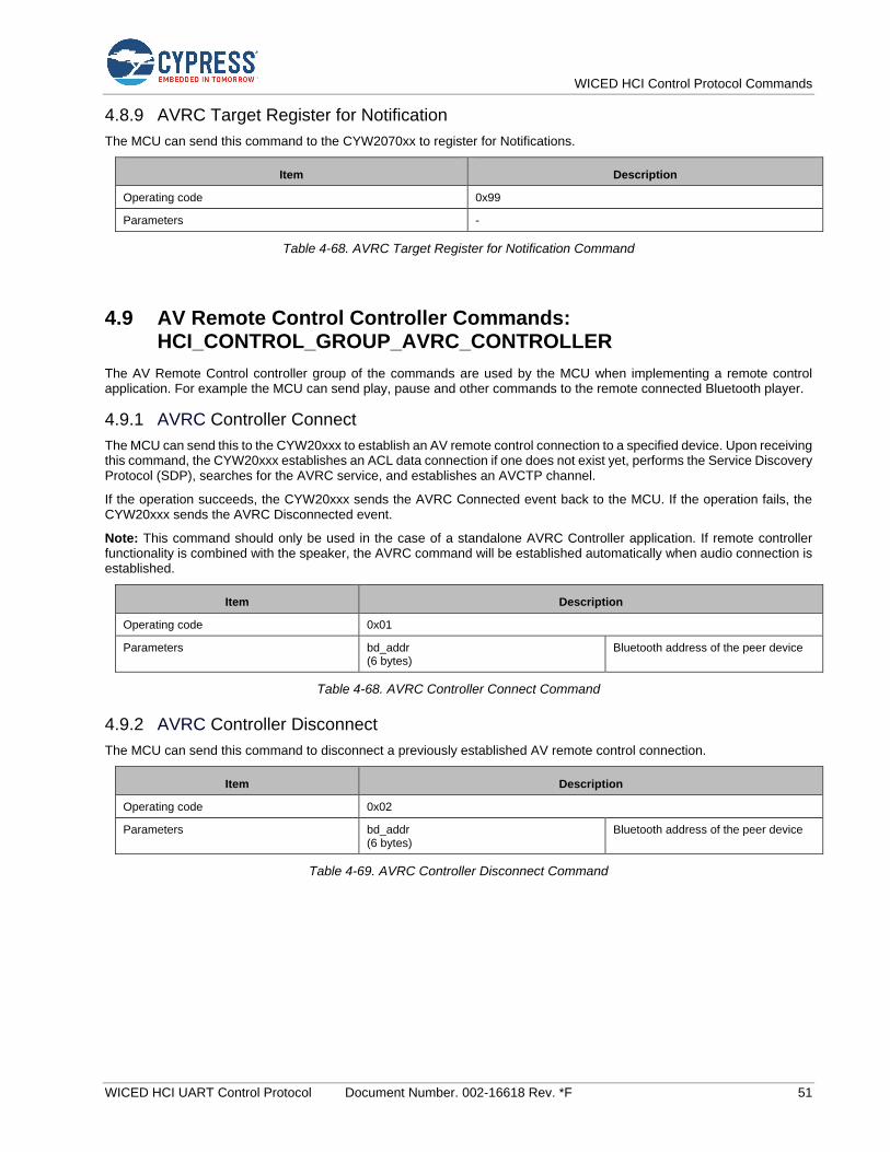
WICED HCI Control Protocol Commands
WICED HCI UART Control Protocol Document Number. 002-16618 Rev. *F 51
4.8.9 AVRC Target Register for Notification
The MCU can send this command to the CYW2070xx to register for Notifications.
Item Description
Operating code 0x99
Parameters -
Table 4-68. AVRC Target Register for Notification Command
4.9 AV Remote Control Controller Commands: HCI_CONTROL_GROUP_AVRC_CONTROLLER
The AV Remote Control controller group of the commands are used by the MCU when implementing a remote control application. For example the MCU can send play, pause and other commands to the remote connected Bluetooth player.
4.9.1 AVRC Controller Connect
The MCU can send this to the CYW20xxx to establish an AV remote control connection to a specified device. Upon receiving this command, the CYW20xxx establishes an ACL data connection if one does not exist yet, performs the Service Discovery Protocol (SDP), searches for the AVRC service, and establishes an AVCTP channel.
If the operation succeeds, the CYW20xxx sends the AVRC Connected event back to the MCU. If the operation fails, the CYW20xxx sends the AVRC Disconnected event.
Note: This command should only be used in the case of a standalone AVRC Controller application. If remote controller functionality is combined with the speaker, the AVRC command will be established automatically when audio connection is established.
Item Description
Operating code 0x01
Parameters bd_addr (6 bytes)
Bluetooth address of the peer device
Table 4-68. AVRC Controller Connect Command
4.9.2 AVRC Controller Disconnect
The MCU can send this command to disconnect a previously established AV remote control connection.
Item Description
Operating code 0x02
Parameters bd_addr (6 bytes)
Bluetooth address of the peer device
Table 4-69. AVRC Controller Disconnect Command

WICED HCI Control Protocol Commands
WICED HCI UART Control Protocol Document Number. 002-16618 Rev. *F 52
4.9.3 AVRC Controller Play
The MCU sends this command to start playing audio on the connected Bluetooth media player.
Item Description
Operating code 0x03
Parameters Connection handle (2 bytes)
The connection handle as reported in the AVRC Connected event (see AVRC Controller Connected).
Table 4-70. AVRC Controller Play Command
4.9.4 AVRC Controller Stop
The MCU sends this command to stop playing audio on the connected Bluetooth media player.
Item Description
Operating code 0x04
Parameters Connection handle (2 bytes)
The connection handle as reported in the AVRC Connected event (see AVRC Controller Connected).
Table 4-71. AVRC Controller Stop Command
4.9.5 AVRC Controller Pause
The MCU sends this command to pause playing audio on the connected Bluetooth media player.
tem Description
Operating code 0x05
Parameters Connection handle (2 bytes)
The connection handle as reported in the AVRC Connected event (see AVRC Controller Connected).
Table 4-72. AVRC Controller Pause Command
4.9.6 AVRC Controller Begin Fast Forward
The MCU sends this command to begin fast forward operation on the connected Bluetooth media player. Unlike most of the other AVRC commands, this command initiates the mode where the player plays audio at high speed. Use the AVRC End Fast Forward command to terminate this mode.
Item Description
Operating code 0x06
Parameters Connection handle (2 bytes)
The connection handle as reported in the AVRC Connected event (see AVRC Controller Connected).
Table 4-73. AVRC Controller Begin Fast Forward Command

WICED HCI Control Protocol Commands
WICED HCI UART Control Protocol Document Number. 002-16618 Rev. *F 53
4.9.7 AVRC Controller End Fast Forward
The MCU sends this command to terminate fast forward operation on the connected Bluetooth media player.
Item Description
Operating code 0x07
Parameters Connection handle (2 bytes)
The connection handle as reported in the AVRC Connected event (see AVRC Controller Connected).
Table 4-74. AVRC Controller End Fast Forward Command
4.9.8 AVRC Controller Begin Rewind
The MCU sends this command to begin rewind operation on the connected Bluetooth media player. Unlike most of the other AVRC commands, this command initiates the mode where the player plays audio in reverse at high speed. Use the AVRC End Rewind command to terminate this mode.
Item Description
Operating code 0x08
Parameters Connection handle (2 bytes)
The connection handle as reported in the AVRC Connected event (see AVRC Controller Connected).
Table 4-75. AVRC Controller Begin Rewind Command
4.9.9 AVRC Controller End Rewind
The MCU sends this command to terminate rewind operation on the connected Bluetooth media player.
Item Description
Operating code 0x09
Parameters Connection handle (2 bytes) The connection handle as reported in the AVRC Connected event (see AVRC Controller Connected).
Table 4-76. AVRC Controller End Rewind Command
4.9.10 AVRC Controller Next Track
The MCU sends this command to instruct the player to move to the next track on the connected Bluetooth media player.
Item Description
Operating code 0x0A
Parameters Connection handle (2 bytes)
The connection handle as reported in the AVRC Connected event (see AVRC Controller Connected).
Table 4-77. AVRC Controller Next Track Command
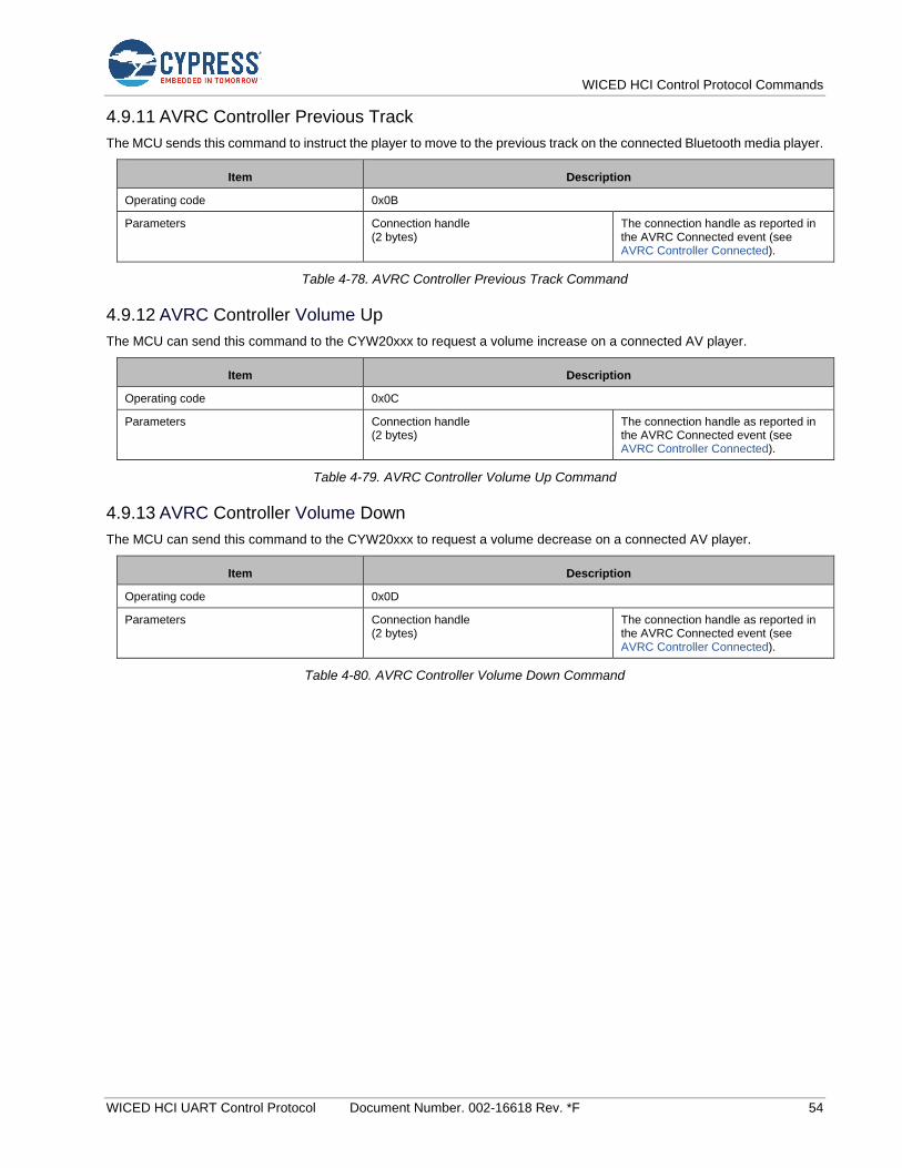
WICED HCI Control Protocol Commands
WICED HCI UART Control Protocol Document Number. 002-16618 Rev. *F 54
4.9.11 AVRC Controller Previous Track
The MCU sends this command to instruct the player to move to the previous track on the connected Bluetooth media player.
Item Description
Operating code 0x0B
Parameters Connection handle (2 bytes)
The connection handle as reported in the AVRC Connected event (see AVRC Controller Connected).
Table 4-78. AVRC Controller Previous Track Command
4.9.12 AVRC Controller Volume Up
The MCU can send this command to the CYW20xxx to request a volume increase on a connected AV player.
Item Description
Operating code 0x0C
Parameters Connection handle (2 bytes)
The connection handle as reported in the AVRC Connected event (see AVRC Controller Connected).
Table 4-79. AVRC Controller Volume Up Command
4.9.13 AVRC Controller Volume Down
The MCU can send this command to the CYW20xxx to request a volume decrease on a connected AV player.
Item Description
Operating code 0x0D
Parameters Connection handle (2 bytes)
The connection handle as reported in the AVRC Connected event (see AVRC Controller Connected).
Table 4-80. AVRC Controller Volume Down Command
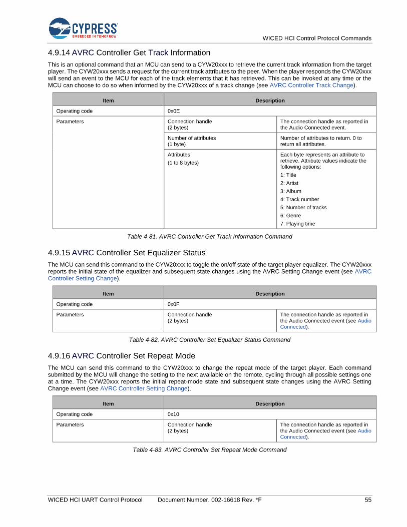
WICED HCI Control Protocol Commands
WICED HCI UART Control Protocol Document Number. 002-16618 Rev. *F 55
4.9.14 AVRC Controller Get Track Information
This is an optional command that an MCU can send to a CYW20xxx to retrieve the current track information from the target player. The CYW20xxx sends a request for the current track attributes to the peer. When the player responds the CYW20xxx will send an event to the MCU for each of the track elements that it has retrieved. This can be invoked at any time or the MCU can choose to do so when informed by the CYW20xxx of a track change (see AVRC Controller Track Change).
Item Description
Operating code 0x0E
Parameters Connection handle (2 bytes)
The connection handle as reported in the Audio Connected event.
Number of attributes (1 byte)
Number of attributes to return. 0 to return all attributes.
Attributes
(1 to 8 bytes)
Each byte represents an attribute to retrieve. Attribute values indicate the following options:
1: Title
2: Artist
3: Album
4: Track number
5: Number of tracks
6: Genre
7: Playing time
Table 4-81. AVRC Controller Get Track Information Command
4.9.15 AVRC Controller Set Equalizer Status
The MCU can send this command to the CYW20xxx to toggle the on/off state of the target player equalizer. The CYW20xxx reports the initial state of the equalizer and subsequent state changes using the AVRC Setting Change event (see AVRC Controller Setting Change).
Item Description
Operating code 0x0F
Parameters Connection handle (2 bytes)
The connection handle as reported in the Audio Connected event (see Audio Connected).
Table 4-82. AVRC Controller Set Equalizer Status Command
4.9.16 AVRC Controller Set Repeat Mode
The MCU can send this command to the CYW20xxx to change the repeat mode of the target player. Each command submitted by the MCU will change the setting to the next available on the remote, cycling through all possible settings one at a time. The CYW20xxx reports the initial repeat-mode state and subsequent state changes using the AVRC Setting Change event (see AVRC Controller Setting Change).
Item Description
Operating code 0x10
Parameters Connection handle (2 bytes)
The connection handle as reported in the Audio Connected event (see Audio Connected).
Table 4-83. AVRC Controller Set Repeat Mode Command

WICED HCI Control Protocol Commands
WICED HCI UART Control Protocol Document Number. 002-16618 Rev. *F 56
4.9.17 AVRC Controller Set Shuffle Mode
The MCU can send this command to the CYW20xxx to change the shuffle mode of the target player. Each command submitted by the MCU will change the setting on the remote to the next available setting, cycling through all possible settings one at a time. The CYW20xxx reports the initial shuffle-mode state and subsequent state changes using the AVRC Setting Change event (see AVRC Controller Setting Change).
Item Description
Operating code 0x11
Parameters Connection handle (2 bytes) The connection handle as reported in the Audio Connected event (see Audio Connected).
Table 4-84. AVRC Controller Set Shuffle Mode Command
4.9.18 VRC Controller Set Scan Status
The MCU can send this command to the CYW20xxx to change the scan status of the target player. Each command submitted by the MCU will change the setting on the remote to the next available setting, cycling through all possible settings one at a time. The CYW20xxx reports the initial scan status and subsequent status changes in the AVRC Setting Change event (see AVRC Controller Setting Change).
Item Description
Operating code 0x12
Parameters Connection handle (2 bytes)
The connection handle as reported in the Audio Connected event (see Audio Connected).
Table 4-85. AVRC Controller Set Scan Status Command
4.9.19 AVRC Controller Set Volume
The MCU can send this command to the CYW20xxx to pass a new volume setting to the connected AV sink device. An MCU should use this command only if the Absolute Volume Capable flag is true as indicated in the Audio Connected event (see Audio Connected).
Item Description
Operating code 0x13
Parameters Connection handle (2 bytes)
The connection handle as reported in the Audio Connected event (see Audio Connected).
Volume level (1 byte)
The percentage (0 to 100) of the maximum volume level to be used by a connected peer device.
Table 4-86. AVRC Controller Set Volume Command
4.9.20 AVRC Get play status
The MCU can send this command to the CYW20xxx to get the status of the currently playing media at the TG.
Item Description
Operating code 0x014
Parameters Connection Handle
(2 bytes)
The connection handle reported in the AVRC Connected event.
Table 4-87. AVRC Controller get play status

WICED HCI Control Protocol Commands
WICED HCI UART Control Protocol Document Number. 002-16618 Rev. *F 57
4.9.21 AVRC Pass through Power Command
The MCU can send this command to the CYW20xxx to invoke AVRC Power Passthrough command.
Item Description
Operating code 0x015
Parameters - -
Table 4-87. AVRC Power Passthrough Command
4.9.22 AVRC Mute
The MCU can send this command to the CYW20xxx to invoke AVRC Mute Passthrough Command.
Item Description
Operating code 0x016
Parameters - -
Table 4-88. AVRC Mute Passthrough Command
4.9.23 AVRC Button Press
The MCU can use this command to simulate a button press on a stereo headphone.
Item Description
Operating code 0x017
Parameters - -
Table 4-89. Simulate a Button Press Command
4.9.24 AVRC Long Button Press
The MCU can use this command to simulate a Long button press on a stereo headphone.
Item Description
Operating code 0x018
Parameters - -
Table 4-90. Simulate a Long Button Press Command
4.9.25 AVRC Unit Info
The MCU can send this command to the CYW20xxx to send a AVRC Unit Info Command.
Item Description
Operating code 0x019
Parameters Connection Handle
(2 bytes)
The connection handle reported in the AVRC Connected event.
Table 4-87. AVRC Controller Send Unit Info Command

WICED HCI Control Protocol Commands
WICED HCI UART Control Protocol Document Number. 002-16618 Rev. *F 58
4.9.26 AVRC Sub Unit Info
The MCU can send this command to the CYW20xxx to send a AVRC Sub Unit Info Command.
Item Description
Operating code 0x01A
Parameters Connection Handle
(2 bytes)
The connection handle reported in the AVRC Connected event.
Table 4-87. AVRC Controller Send Sub Unit Info Command
4.10 Test Commands— HCI_CONTROL_GROUP_TEST
The Test commands allow the host to execute various tests on the CYW20xxx.
4.10.1 Encapsulated HCI Command
Primarily for manufacturing test purposes, this test command allows the host to send encapsulated HCI commands to the CYW20xxx to control the BT controller for RF test purposes. For example, Bluetooth LE RF testing usually requires the support of the LE Transmitter Test, LE Receiver Test, and LE Test End HCI commands (see BLUETOOTH SPECIFICATION Version 4.2 [Vol 2, Part E], Section 7.8.28, 7.8.29, and 7.8.30 [2] for details). All of which can be formatted into this Encapsulated HCI Command.
The CYW20xxx also provides support for vendor-specific commands (Radio_Tx_Test and Radio_Rx_Test) which enable a connectionless transmit and receive mode to send and receive respectively Bluetooth packets at a specified frequency. See the WMBT tool included in with the wiced_btsdk project under <USER_HOME>\mtw\wiced_btsdk\tools\btsdk-utils\wmbt.
When the CYW20xxx receives a test command, it is put into a Test Mode. While in the Test Mode all the events received from the controller are passed to the MCU as Encapsulated HCI Events (see Encapsulated HCI Event) and not processed by the stack. Because of that the CYW20xxx must be reset and reinitialized to continue normal application operation.
Item Description
Operating code 0x10
Parameters HCI Command (variable bytes) Fully formatted HCI Command.
Table 4-87. Encapsulated HCI Command
4.11 ANCS Commands: HCI_CONTROL_GROUP_ANCS
The Apple Notification Control Service (ANCS) commands let an MCU perform various ANCS-related procedures using the CYW20xxx. Refer to the Apple ANCS Specification [3] for more information.
4.11.1 ANCS Action
This command instructs the CYW20xxx to pass a positive or negative action with respect to a specific notification sent by the iOS device. The command is sent after the CYW20xxx reports the notification in the ANCS Notification event (see ANCS Notification).
Item Description
Operating code 0x01
Parameters Notification ID (4 bytes)
The Notification ID as reported in the ANCS Notification Event.
Action (1 byte)
0: Positive action.
1: Negative action.
Table 4-88. ANCS Action Command

WICED HCI Control Protocol Commands
WICED HCI UART Control Protocol Document Number. 002-16618 Rev. *F 59
4.11.2 ANCS Connect
This command instructs the CYW20xxx to activate the ANCS service on the iOS device connected to the given LE Connection Handle. The MCU should not send this command until after it has received the ANCS Service Found event and has verified that the LE connection is Encrypted since the ANCS service requires Authentication.
Item Description
Operating code 0x02
Parameters Connection Handle
(2 bytes)
The connection handle reported in the LE Connected event.
Table 4-89. ANCS Connect Command
4.11.3 ANCS Disconnect
This command instructs the CYW20xxx to deactivate the ANCS service on the iOS device connected to the given LE Connection Handle by unsubscribing to notifications for the service.
Item Description
Operating code 0x03
Parameters Connection Handle
(2 bytes)
The connection handle reported in the LE Connected event.
Table 4-90. ANCS Disconnect Command
4.12 AMS Commands: HCI_CONTROL_GROUP_AMS
The Apple Media Service (AMS) commands let an MCU perform various AMS-related procedures using the CYW20xxx. Refer to the Apple developer AMS Specification [4] for more information:
4.12.1 AMS Connect
This command instructs the CYW20xxx to activate the AMS service on the iOS device connected to the given LE Connection Handle. The MCU should not send this command until after it has received the AMS Service Found event and has verified that the LE connection is Encrypted since the AMS service requires Authentication.
Item Description
Operating code 0x01
Parameters Connection Handle
(2 bytes)
The connection handle reported in the LE Connected event.
Table 4-91. AMS Connect Command
4.12.2 AMS Disconnect
This command instructs the CYW20xxx to deactivate the AMS service on the iOS device connected to the given LE Connection Handle by unsubscribing to notifications for the service.
Item Description
Operating code 0x02
Parameters Connection Handle
(2 bytes)
The connection handle reported in the LE Connected event.
Table 4-92. AMS Disconnect Command

WICED HCI Control Protocol Commands
WICED HCI UART Control Protocol Document Number. 002-16618 Rev. *F 60
4.13 iAP2 Commands: HCI_CONTROL_GROUP_IAP2
The Apple iPod Accessory Protocol (iAP2) commands allows an MCU to establish and send data over an iAP2 External Accessory (EA) session implemented on a CYW20xxx.
4.13.1 IAP2 Connect
The MCU can send this command to the CYW20xxx to establish an EA session with a specified device. Upon receiving the command, the CYW20xxx establishes an ACL data connection, performs an SDP search for the iAP2 service, and establishes an EA session to the iAP2 service.
After the EA session is successfully established, the CYW20xxx will send an IAP2 Connected event (see IAP2 Connected) back to the MCU. If the operation fails, then either the IAP2 Connection Failed event (see IAP2 Connection Failed) or IAP2 Service Not Found event (see IAP2 Service Not Found) is sent.
Item Description
Operating code 0x01
Parameters bd_addr (6 bytes)
Bluetooth address of the peer device.
Table 4-93. IAP2 Connect Command
4.13.2 IAP2 Disconnect
The MCU can send this command to disconnect a previously established EA session.
Item Description
Operating code 0x02
Parameters Session handle (2 bytes)
The session handle as reported in the IAP2 Connected event (see IAP2 Connected).
Table 4-94. IAP2 Disconnect Command
4.13.3 IAP2 Data
An MCU issues this command to send data over an established EA session.
Upon receiving this command, the CYW20xxx attempts to allocate a buffer and queue a data packet for transmission. After successfully enqueuing a packet, the CYW20xxx sends the IAP2 TX Complete event (see IAP2 TX Complete). If the queue is full because data is received over the UART faster than it can be delivered to the peer, then the sending of the TX Completed event is delayed until after the packet is successfully enqueued.
Item Description
Operating code 0x03
Parameters Session handle (2 bytes)
The session handle as reported in the IAP2 Connected event (see IAP2 Connected).
Data
(variable bytes)
Data to be transmitted to the iOS device.
Table 4-95. IAP2 Data Command

WICED HCI Control Protocol Commands
WICED HCI UART Control Protocol Document Number. 002-16618 Rev. *F 61
4.13.4 IAP2 Get Auth Chip Info
The MCU can send this command to read the chip information from the authentication coprocessor connected to the CYW20xxx.
Item Description
Operating code 0x04
Parameters -
Table 4-96. IAP2 Get Auth Chip Info Command
4.14 Hands-free AG Commands: HCI_CONTROL_GROUP_AG
The Hands-free AG commands let an MCU establish signaling and audio connections to a peer hands-free device. The current version of the protocol defined in this document supports a simple implementation that can be used only for voice control and not for actual calls, conferences, and more.
4.14.1 AG Connect
An MCU can send this command to the CYW20xxx to establish an hands-free audio gateway connection to a specified device. Upon receiving the command, the CYW20xxx establishes an ACL data connection, performs an SDP search for the RFCOMM service, establishes a connection with the RFCOMM service, and establishes a signaling connection with the specified hands-free device.
After an AG connection is successfully established, the CYW20xxx will send the AG Connected event (see AG Connected) back to the MCU.
Item Description
Operating code 0x01
Parameters bd_addr (6 bytes)
Bluetooth address of the peer device.
Table 4-97. AG Connect Command
4.14.2 AG Disconnect
An MCU can send this command to disconnect a previously established AG signaling connection.
Item Description
Operating code 0x02
Parameters Session handle (2 bytes) The session handle as reported in the AG Connected event (see
AG Connected).
Table 4-98. AG Disconnect Command
4.14.3 AG Audio Connect
An MCU can send this command to establish an audio channel over a previously established AG signaling connection.
Item Description
Operating code 0x03
Parameters Session handle (2 bytes)
The session handle as reported in the AG Connected event (see
AG Connected).
Table 4-99. AG Audio Connect Command
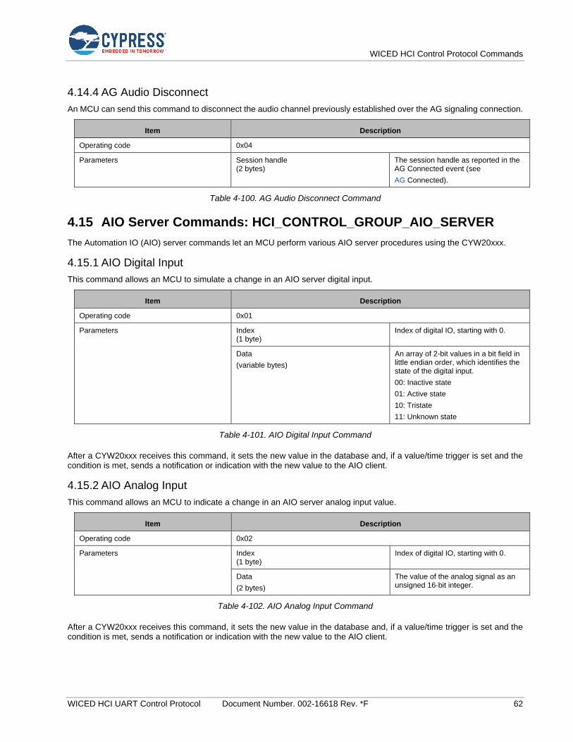
WICED HCI Control Protocol Commands
WICED HCI UART Control Protocol Document Number. 002-16618 Rev. *F 62
4.14.4 AG Audio Disconnect
An MCU can send this command to disconnect the audio channel previously established over the AG signaling connection.
Item Description
Operating code 0x04
Parameters Session handle (2 bytes)
The session handle as reported in the AG Connected event (see
AG Connected).
Table 4-100. AG Audio Disconnect Command
4.15 AIO Server Commands: HCI_CONTROL_GROUP_AIO_SERVER
The Automation IO (AIO) server commands let an MCU perform various AIO server procedures using the CYW20xxx.
4.15.1 AIO Digital Input
This command allows an MCU to simulate a change in an AIO server digital input.
Item Description
Operating code 0x01
Parameters Index (1 byte)
Index of digital IO, starting with 0.
Data
(variable bytes)
An array of 2-bit values in a bit field in little endian order, which identifies the state of the digital input.
00: Inactive state
01: Active state
10: Tristate
11: Unknown state
Table 4-101. AIO Digital Input Command
After a CYW20xxx receives this command, it sets the new value in the database and, if a value/time trigger is set and the condition is met, sends a notification or indication with the new value to the AIO client.
4.15.2 AIO Analog Input
This command allows an MCU to indicate a change in an AIO server analog input value.
Item Description
Operating code 0x02
Parameters Index (1 byte)
Index of digital IO, starting with 0.
Data
(2 bytes)
The value of the analog signal as an unsigned 16-bit integer.
Table 4-102. AIO Analog Input Command
After a CYW20xxx receives this command, it sets the new value in the database and, if a value/time trigger is set and the condition is met, sends a notification or indication with the new value to the AIO client.
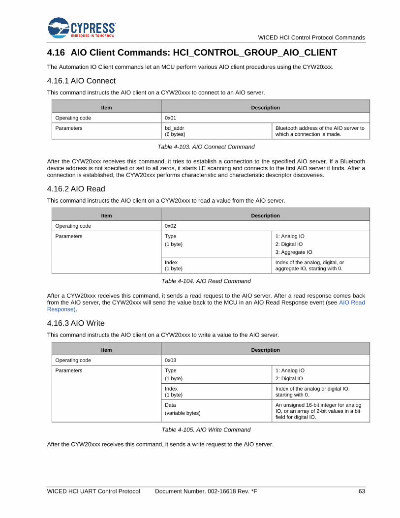
WICED HCI Control Protocol Commands
WICED HCI UART Control Protocol Document Number. 002-16618 Rev. *F 63
4.16 AIO Client Commands: HCI_CONTROL_GROUP_AIO_CLIENT
The Automation IO Client commands let an MCU perform various AIO client procedures using the CYW20xxx.
4.16.1 AIO Connect
This command instructs the AIO client on a CYW20xxx to connect to an AIO server.
Item Description
Operating code 0x01
Parameters bd_addr (6 bytes)
Bluetooth address of the AIO server to which a connection is made.
Table 4-103. AIO Connect Command
After the CYW20xxx receives this command, it tries to establish a connection to the specified AIO server. If a Bluetooth device address is not specified or set to all zeros, it starts LE scanning and connects to the first AIO server it finds. After a connection is established, the CYW20xxx performs characteristic and characteristic descriptor discoveries.
4.16.2 AIO Read
This command instructs the AIO client on a CYW20xxx to read a value from the AIO server.
Item Description
Operating code 0x02
Parameters Type
(1 byte)
1: Analog IO
2: Digital IO
3: Aggregate IO
Index (1 byte)
Index of the analog, digital, or aggregate IO, starting with 0.
Table 4-104. AIO Read Command
After a CYW20xxx receives this command, it sends a read request to the AIO server. After a read response comes back from the AIO server, the CYW20xxx will send the value back to the MCU in an AIO Read Response event (see AIO Read Response).
4.16.3 AIO Write
This command instructs the AIO client on a CYW20xxx to write a value to the AIO server.
Item Description
Operating code 0x03
Parameters Type
(1 byte)
1: Analog IO
2: Digital IO
Index (1 byte)
Index of the analog or digital IO, starting with 0.
Data
(variable bytes)
An unsigned 16-bit integer for analog IO, or an array of 2-bit values in a bit field for digital IO.
Table 4-105. AIO Write Command
After the CYW20xxx receives this command, it sends a write request to the AIO server.
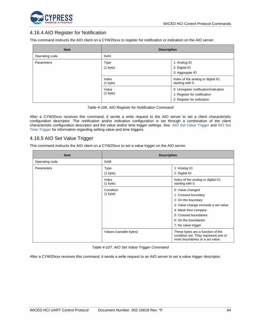
WICED HCI Control Protocol Commands
WICED HCI UART Control Protocol Document Number. 002-16618 Rev. *F 64
4.16.4 AIO Register for Notification
This command instructs the AIO client on a CYW20xxx to register for notification or indication on the AIO server.
Item Description
Operating code 0x04
Parameters Type
(1 byte)
1: Analog IO
2: Digital IO
3: Aggregate IO
Index (1 byte)
Index of the analog or digital IO, starting with 0.
Value (1 byte)
0: Unregister notification/indication
1: Register for notification
2: Register for indication
Table 4-106. AIO Register for Notification Command
After a CYW20xxx receives this command, it sends a write request to the AIO server to set a client characteristic configuration descriptor. The notification and/or indication configuration is set through a combination of the client characteristic configuration descriptor and the value and/or time trigger settings. See AIO Set Value Trigger and AIO Set Time Trigger for information regarding setting value and time triggers.
4.16.5 AIO Set Value Trigger
This command instructs the AIO client on a CYW20xxx to set a value trigger on the AIO server.
Item Description
Operating code 0x06
Parameters Type
(1 byte)
1: Analog IO
2: Digital IO
Index (1 byte)
Index of the analog or digital IO, starting with 0.
Condition (1 byte)
0: Value changed
1: Crossed boundary
2: On the boundary
3: Value change exceeds a set value
4: Mask then compare
5: Crossed boundaries
6: On the boundaries
7: No value trigger
Values (variable bytes) These bytes are a function of the condition set. They represent one or more boundaries or a set value.
Table 4-107. AIO Set Value Trigger Command
After a CYW20xxx receives this command, it sends a write request to an AIO server to set a value trigger descriptor.
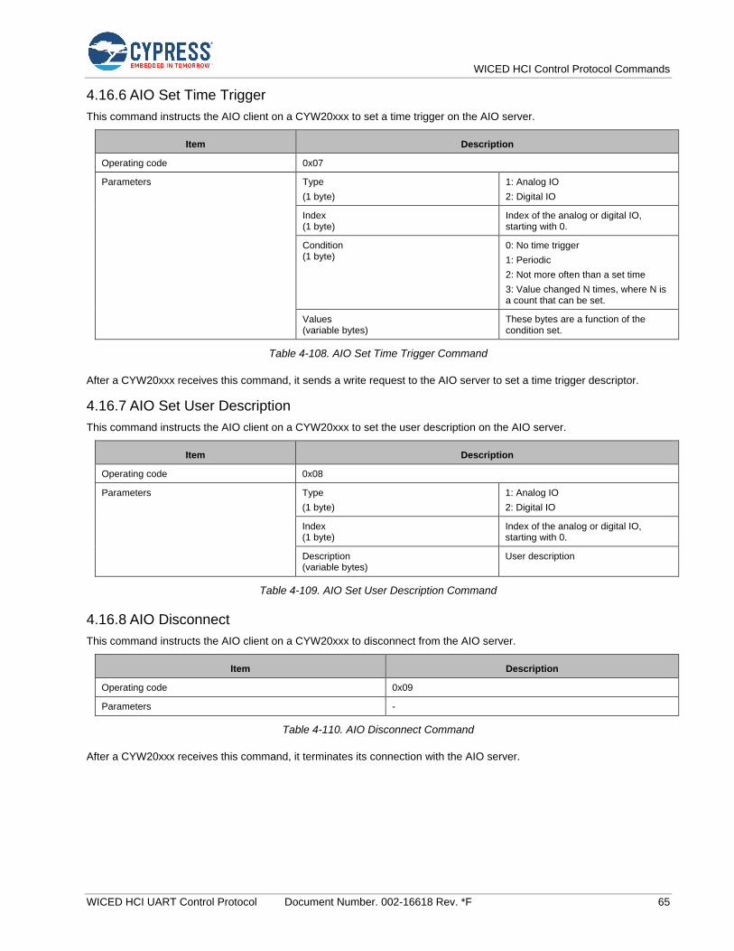
WICED HCI Control Protocol Commands
WICED HCI UART Control Protocol Document Number. 002-16618 Rev. *F 65
4.16.6 AIO Set Time Trigger
This command instructs the AIO client on a CYW20xxx to set a time trigger on the AIO server.
Item Description
Operating code 0x07
Parameters Type
(1 byte)
1: Analog IO
2: Digital IO
Index (1 byte)
Index of the analog or digital IO, starting with 0.
Condition (1 byte)
0: No time trigger
1: Periodic
2: Not more often than a set time
3: Value changed N times, where N is a count that can be set.
Values (variable bytes)
These bytes are a function of the condition set.
Table 4-108. AIO Set Time Trigger Command
After a CYW20xxx receives this command, it sends a write request to the AIO server to set a time trigger descriptor.
4.16.7 AIO Set User Description
This command instructs the AIO client on a CYW20xxx to set the user description on the AIO server.
Item Description
Operating code 0x08
Parameters Type
(1 byte)
1: Analog IO
2: Digital IO
Index (1 byte)
Index of the analog or digital IO, starting with 0.
Description (variable bytes)
User description
Table 4-109. AIO Set User Description Command
4.16.8 AIO Disconnect
This command instructs the AIO client on a CYW20xxx to disconnect from the AIO server.
Item Description
Operating code 0x09
Parameters -
Table 4-110. AIO Disconnect Command
After a CYW20xxx receives this command, it terminates its connection with the AIO server.

WICED HCI Control Protocol Commands
WICED HCI UART Control Protocol Document Number. 002-16618 Rev. *F 66
4.17 Audio Sink Commands: HCI_CONTROL_GROUP_AUDIO_SINK
The audio sink commands let an MCU establish an AV sink connection to a peer device over the AVDT protocol.
4.17.1 Audio Sink Connect
The Audio Sink Connect command instructs the CYW20xxx to establish an AV Sink connection to a specified device. Upon receiving the command, the CYW20xxx establishes an ACL data connection, performs Service Discovery Protocol (SDP) searches for the A2DP service, and establishes an AVDTP signaling connection. It is source responsibility to discover and configure streaming endpoint.
If the operation succeeds, the CYW20xxx will send the Audio Sink Connected event back to the MCU. If the operation fails, the Audio Sink Connection Failed, or Audio Sink Service Not Found event is sent.
Item Description
Operating code 0x01
Parameters Address (6 bytes)
Bluetooth device address of the peer device.
Table 4-111. Audio Sink Connect Command
4.17.2 Audio Sink Disconnect
The Audio Sink Disconnect command instructs the CYW20xxx to disconnect a previously established AV sink connection.
Item Description
Operating code 0x02
Parameters Connection handle (2 bytes) The connection handle as reported in the Audio Sink Connected event.
Table 4-112. Audio Sink Disconnect Command
4.17.3 Audio Sink Start
The Audio Sink Start command instructs the CYW20xxx to send start audio streaming request from the MCU to the remote device. Upon receiving the command, if the CYW20xxx determines that it’s appropriate and necessary, it configures the codec settings, audio route and sends AVDTP START request to peer device.
The MCU can send an Audio Sink Start command only after an audio sink connection to the peer device has been established; that is, after an Audio Sink Connected event has been received (see Audio Sink Connected).
If the MCU was streaming data and issued the Audio Sink Stop command (see Audio Sink Stop), it should not send another Audio Sink Start command until it receives the Audio Sink Stopped event (see Audio Sink Stopped).
If the operation is successful, then the CYW20xxx will send the Audio Sink Started event (see Audio Sink Started) back to the MCU. If the operation fails, the Audio Stopped event (see Audio Sink Stopped) will be sent.
Item Description
Operating code 0x03
Parameters Connection handle (2 bytes)
The connection handle as reported in the Audio Connected event.
Table 4-113. Audio Sink Start Command
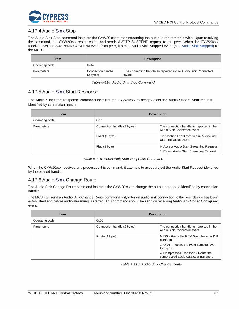
WICED HCI Control Protocol Commands
WICED HCI UART Control Protocol Document Number. 002-16618 Rev. *F 67
4.17.4 Audio Sink Stop
The Audio Sink Stop command instructs the CYW20xxx to stop streaming the audio to the remote device. Upon receiving the command, the CYW20xxx resets codec and sends AVDTP SUSPEND request to the peer. When the CYW20xxx receives AVDTP SUSPEND CONFIRM event from peer, it sends Audio Sink Stopped event (see Audio Sink Stopped) to the MCU.
Item Description
Operating code 0x04
Parameters Connection handle (2 bytes)
The connection handle as reported in the Audio Sink Connected event.
Table 4-114. Audio Sink Stop Command
4.17.5 Audio Sink Start Response
The Audio Sink Start Response command instructs the CYW20xxx to accept/reject the Audio Stream Start request
identified by connection handle.
Item Description
Operating code 0x05
Parameters Connection handle (2 bytes) The connection handle as reported in the Audio Sink Connected event.
Label (1 byte) Transaction Label received in Audio Sink Start Indication event.
Flag (1 byte) 0: Accept Audio Start Streaming Request
1: Reject Audio Start Streaming Request
Table 4-115. Audio Sink Start Response Command
When the CYW20xxx receives and processes this command, it attempts to accept/reject the Audio Start Request identified by the passed handle.
4.17.6 Audio Sink Change Route
The Audio Sink Change Route command instructs the CYW20xxx to change the output data route identified by connection handle.
The MCU can send an Audio Sink Change Route command only after an audio sink connection to the peer device has been established and before audio streaming is started. This command should be send on receiving Audio Sink Codec Configured event.
Item Description
Operating code 0x06
Parameters Connection handle (2 bytes) The connection handle as reported in the Audio Sink Connected event.
Route (1 byte) 0: I2S - Route the PCM Samples over I2S (Default)
1: UART - Route the PCM samples over transport
4: Compressed Transport - Route the compressed audio data over transport.
Table 4-116. Audio Sink Change Route
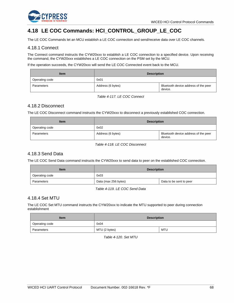
WICED HCI Control Protocol Commands
WICED HCI UART Control Protocol Document Number. 002-16618 Rev. *F 68
4.18 LE COC Commands: HCI_CONTROL_GROUP_LE_COC
The LE COC Commands let an MCU establish a LE COC connection and send/receive data over LE COC channels.
4.18.1 Connect
The Connect command instructs the CYW20xxx to establish a LE COC connection to a specified device. Upon receiving the command, the CYW20xxx establishes a LE COC connection on the PSM set by the MCU.
If the operation succeeds, the CYW20xxx will send the LE COC Connected event back to the MCU.
Item Description
Operating code 0x01
Parameters Address (6 bytes) Bluetooth device address of the peer device.
Table 4-117. LE COC Connect
4.18.2 Disconnect
The LE COC Disconnect command instructs the CYW20xxx to disconnect a previously established COC connection.
Item Description
Operating code 0x02
Parameters Address (6 bytes) Bluetooth device address of the peer device.
Table 4-118. LE COC Disconnect
4.18.3 Send Data
The LE COC Send Data command instructs the CYW20xxx to send data to peer on the established COC connection.
Item Description
Operating code 0x03
Parameters Data (max 256 bytes) Data to be sent to peer
Table 4-119. LE COC Send Data
4.18.4 Set MTU
The LE COC Set MTU command instructs the CYW20xxx to indicate the MTU supported to peer during connection establishment
Item Description
Operating code 0x04
Parameters MTU (2 bytes) MTU
Table 4-120. Set MTU
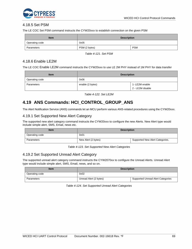
WICED HCI Control Protocol Commands
WICED HCI UART Control Protocol Document Number. 002-16618 Rev. *F 69
4.18.5 Set PSM
The LE COC Set PSM command instructs the CYW20xxx to establish connection on the given PSM
Item Description
Operating code 0x05
Parameters PSM (2 bytes) PSM
Table 4-121. Set PSM
4.18.6 Enable LE2M
The LE COC Enable LE2M command instructs the CYW20xxx to use LE 2M PHY instead of 1M PHY for data transfer
Item Description
Operating code 0x06
Parameters enable (2 bytes) 1- LE2M enable
2 - LE2M disable
Table 4-122. Set LE2M
4.19 ANS Commands: HCI_CONTROL_GROUP_ANS
The Alert Notification Service (ANS) commands let an MCU perform various ANS-related procedures using the CYW20xxx.
4.19.1 Set Supported New Alert Category
The supported new alert category command instructs the CYW20xxx to configure the new Alerts. New Alert type would include simple alert, SMS, Email, news etc.
Item Description
Operating code 0x01
Parameters New Alert (2 bytes) Supported New Alert Categories.
Table 4-123. Set Supported New Alert Categories
4.19.2 Set Supported Unread Alert Category
The supported unread alert category command instructs the CYW2070xx to configure the Unread Alerts. Unread Alert
type would include simple alert, SMS, Email, news, and so on.
Item Description
Operating code 0x02
Parameters Unread Alert (2 bytes) Supported Unread Alert Categories
Table 4-124. Set Supported Unread Alert Categories

WICED HCI Control Protocol Commands
WICED HCI UART Control Protocol Document Number. 002-16618 Rev. *F 70
4.19.3 Generate Alerts
The Generate Alerts command instructs the CYW20xxx to Generate a specific type of Alert. This can be used to generate both New Alert and Unread Alert of a specific category.
Item Description
Operating code 0x03
Parameters Alert (1 byte) Generate the Required type of Alert.
Table 4-125.Generate Alerts
4.19.4 Clear Alerts
The Clear Alert command instructs the CYW20xxx to clear the previously generated alert count. This can be used to clear previously received alert count for both New Alert and Unread Alert of a specific category.
Item Description
Operating code 0x04
Parameters Alert (1 byte) Clear the Required type of Alert.
Table 4-126. Clear Alerts
4.20 ANC Commands: HCI_CONTROL_GROUP_ANC
The Alert Notification Client commands lets an MCU to perform various ANC related procedures using the CYW2070xx.
4.20.1 Read Server Supported New Alerts
The Read Server Supported New Alerts command instructs CYW20xxx to read the Supported New Alert Category from Alert Notification Server.
Note: New Alerts Radio button should be selected before issuing the command.
Item Description
Operating code 0x01
Table 4-127. Read Server Supported New Alerts
4.20.2 Read Server Supported Unread Alerts
The Read Server Supported Unread Alerts command instructs CYW20xxx to read the Supported Unread Alert Category from Alert Notification Server.
Note: Unread Alerts Radio button should be selected before issuing the command.
Item Description
Operating code 0x02
Table 4-128. Read Server Supported Unread Alerts

WICED HCI Control Protocol Commands
WICED HCI UART Control Protocol Document Number. 002-16618 Rev. *F 71
4.20.3 Control Alerts
The Control Alert command instructs CYW2070xx to enable, disable, notify all the pending alerts.
Item Description
Operating code 0x03
Parameters Command ID (1 byte) This is the type of Alert (New Alert/ Unread Alert) which needs to be sent.
Alert Category (1 byte) This indicates the specific Alert type category. (e.g. Email, SMS, simple alert)
Table 4-129. Control Alerts
4.20.4 Enable New Alert
The Enable New Alert command instructs CYW20xxx to enable New Alert Type Notifications.
Item Description
Operating code 0x04
Table 4-130. Enable New Alert
4.20.5 Enable Unread Alert
The Enable Unread Alert command instructs CYW20xxx to enable Unread Alert Type Notifications.
Item Description
Operating code 0x05
Table 4-131. Enable Unread Alert
4.20.6 Disable New Alert
The Disable New Alert command instructs CYW20xxx to disable New Alert Type Notifications.
Item Description
Operating code 0x06
Table 4-132. Disable New Alert
4.20.7 Disable Unread Alert
The Disable Unread Alert command instructs CYW20xxx to disable Unread Alert Type Notifications.
Item Description
Operating code 0x07
Table 4-133.Disable Unread Alert

WICED HCI Control Protocol Commands
WICED HCI UART Control Protocol Document Number. 002-16618 Rev. *F 72
4.21 Miscellaneous Commands: HCI_CONTROL_GROUP_MISC
The miscellaneous commands allow the host to send the general commands as defined by the CYW20xxx.
4.21.1 Ping Request
This miscellaneous command sends a Ping Request to the CYW20xxx. The application running on the CYW20xxx is expected to respond back with a Ping Reply event (see Ping Request Reply). The Ping Reply event is expected to return the data sent as part of the Ping Request.
Item Description
Operating code 0x01
Parameters Data (variable bytes)
Table 4-134. Ping Request Command
4.21.2 Get Version
This miscellaneous command requests the CYW20xxx to report the ModusToolbox version used to build the embedded application. The application running on the CYW20xxx is expected to respond back with a Version Info event (see

WICED HCI Control Protocol Commands
WICED HCI UART Control Protocol Document Number. 002-16618 Rev. *F 73
Version Info).
Item Description
Operating code 0x02
Table 4-135. Get Version Command
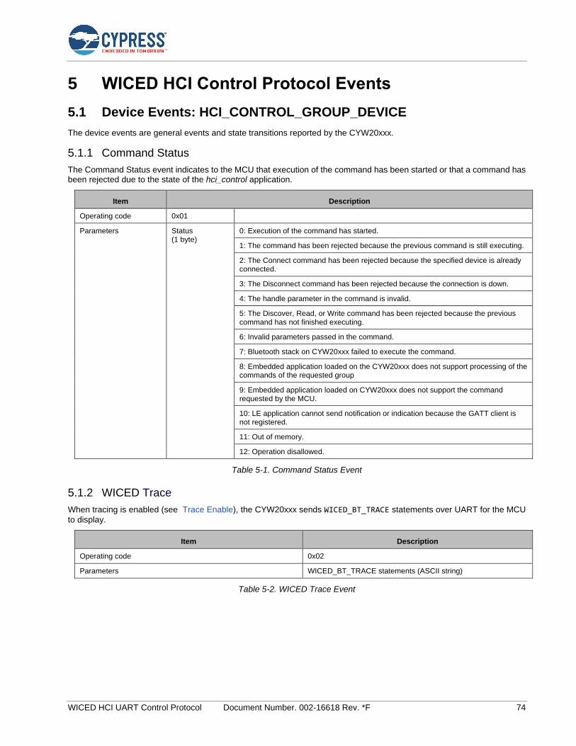
WICED HCI UART Control Protocol Document Number. 002-16618 Rev. *F 74
5 WICED HCI Control Protocol Events
5.1 Device Events: HCI_CONTROL_GROUP_DEVICE
The device events are general events and state transitions reported by the CYW20xxx.
5.1.1 Command Status
The Command Status event indicates to the MCU that execution of the command has been started or that a command has been rejected due to the state of the hci_control application.
Item Description
Operating code 0x01
Parameters Status (1 byte)
0: Execution of the command has started.
1: The command has been rejected because the previous command is still executing.
2: The Connect command has been rejected because the specified device is already connected.
3: The Disconnect command has been rejected because the connection is down.
4: The handle parameter in the command is invalid.
5: The Discover, Read, or Write command has been rejected because the previous command has not finished executing.
6: Invalid parameters passed in the command.
7: Bluetooth stack on CYW20xxx failed to execute the command.
8: Embedded application loaded on the CYW20xxx does not support processing of the commands of the requested group
9: Embedded application loaded on CYW20xxx does not support the command requested by the MCU.
10: LE application cannot send notification or indication because the GATT client is not registered.
11: Out of memory.
12: Operation disallowed.
Table 5-1. Command Status Event
5.1.2 WICED Trace
When tracing is enabled (see Trace Enable), the CYW20xxx sends WICED_BT_TRACE statements over UART for the MCU
to display.
Item Description
Operating code 0x02
Parameters WICED_BT_TRACE statements (ASCII string)
Table 5-2. WICED Trace Event
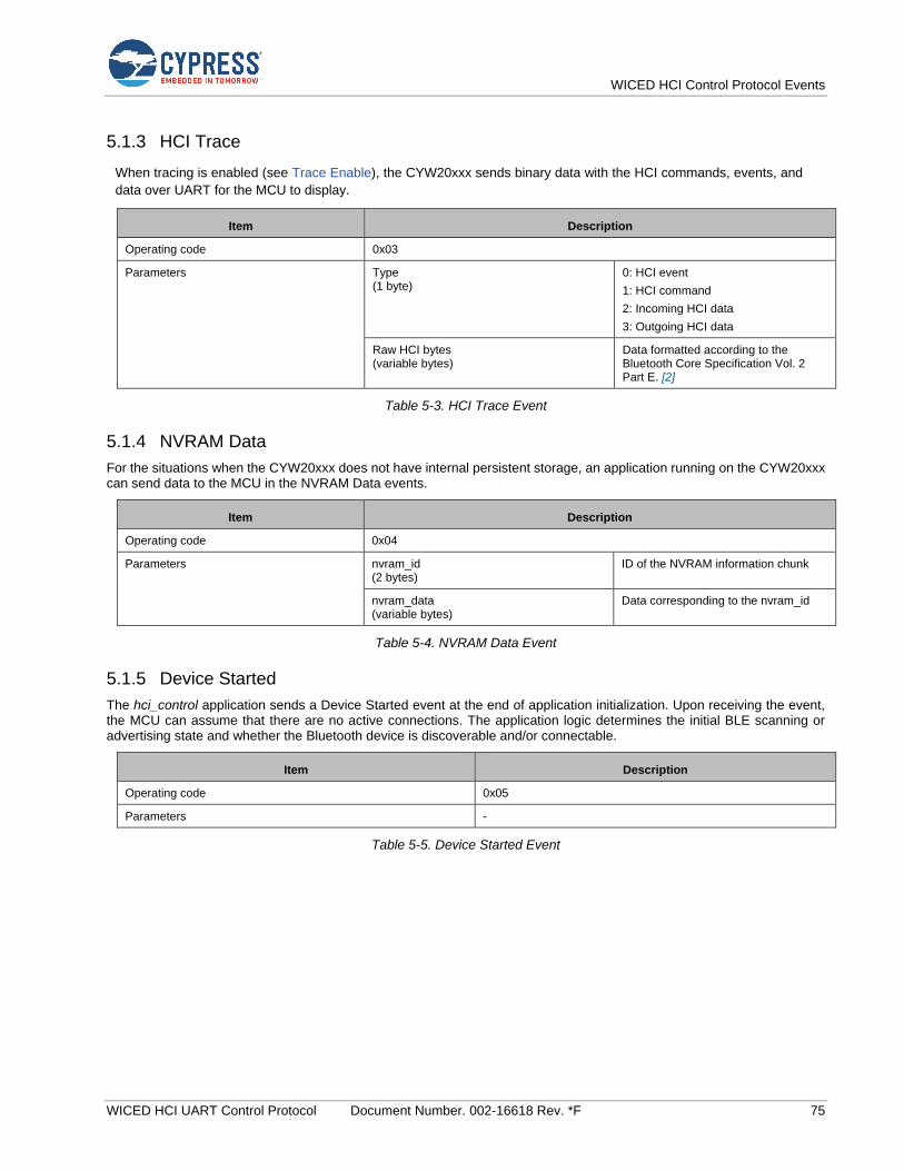
WICED HCI Control Protocol Events
WICED HCI UART Control Protocol Document Number. 002-16618 Rev. *F 75
5.1.3 HCI Trace
When tracing is enabled (see Trace Enable), the CYW20xxx sends binary data with the HCI commands, events, and
data over UART for the MCU to display.
Item Description
Operating code 0x03
Parameters Type (1 byte)
0: HCI event
1: HCI command
2: Incoming HCI data
3: Outgoing HCI data
Raw HCI bytes (variable bytes)
Data formatted according to the Bluetooth Core Specification Vol. 2 Part E. [2]
Table 5-3. HCI Trace Event
5.1.4 NVRAM Data
For the situations when the CYW20xxx does not have internal persistent storage, an application running on the CYW20xxx can send data to the MCU in the NVRAM Data events.
Item Description
Operating code 0x04
Parameters nvram_id (2 bytes)
ID of the NVRAM information chunk
nvram_data (variable bytes)
Data corresponding to the nvram_id
Table 5-4. NVRAM Data Event
5.1.5 Device Started
The hci_control application sends a Device Started event at the end of application initialization. Upon receiving the event, the MCU can assume that there are no active connections. The application logic determines the initial BLE scanning or advertising state and whether the Bluetooth device is discoverable and/or connectable.
Item Description
Operating code 0x05
Parameters -
Table 5-5. Device Started Event
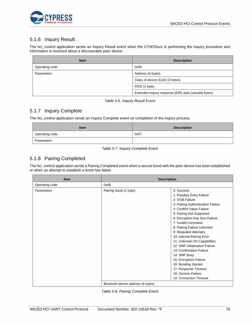
WICED HCI Control Protocol Events
WICED HCI UART Control Protocol Document Number. 002-16618 Rev. *F 76
5.1.6 Inquiry Result
The hci_control application sends an Inquiry Result event when the CYW20xxx is performing the inquiry procedure and information is received about a discoverable peer device.
Item Description
Operating code 0x06
Parameters Address (6 bytes)
Class of device (CoD) (3 bytes)
RSSI (1 byte)
Extended inquiry response (EIR) data (variable bytes)
Table 5-6. Inquiry Result Event
5.1.7 Inquiry Complete
The hci_control application sends an Inquiry Complete event on completion of the inquiry process.
Item Description
Operating code 0x07
Parameters -
Table 5-7. Inquiry Complete Event
5.1.8 Pairing Completed
The hci_control application sends a Pairing Completed event when a secure bond with the peer device has been established or when an attempt to establish a bond has failed.
Item Description
Operating code 0x08
Parameters Pairing result (1 byte): 0: Success
1: Passkey Entry Failure
2: OOB Failure
3: Pairing Authentication Failure
4: Confirm Value Failure
5: Pairing Not Supported
6: Encryption Key Size Failure
7: Invalid Command
8: Pairing Failure Unknown
9: Repeated Attempts
10: Internal Pairing Error
11: Unknown I/O Capabilities
12: SMP Initialization Failure
13: Confirmation Failure
14: SMP Busy
15: Encryption Failure
16: Bonding Started
17: Response Timeout
18: Generic Failure
19: Connection Timeout
Bluetooth device address (6 bytes)
Table 5-8. Pairing Complete Event
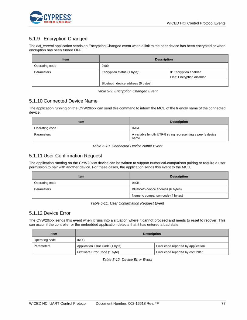
WICED HCI Control Protocol Events
WICED HCI UART Control Protocol Document Number. 002-16618 Rev. *F 77
5.1.9 Encryption Changed
The hci_control application sends an Encryption Changed event when a link to the peer device has been encrypted or when encryption has been turned OFF.
Item Description
Operating code 0x09
Parameters Encryption status (1 byte): 0: Encryption enabled
Else: Encryption disabled
Bluetooth device address (6 bytes)
Table 5-9. Encryption Changed Event
5.1.10 Connected Device Name
The application running on the CYW20xxx can send this command to inform the MCU of the friendly name of the connected device.
Item Description
Operating code 0x0A
Parameters A variable length UTF-8 string representing a peer’s device name.
Table 5-10. Connected Device Name Event
5.1.11 User Confirmation Request
The application running on the CYW20xxx device can be written to support numerical-comparison pairing or require a user permission to pair with another device. For these cases, the application sends this event to the MCU.
Item Description
Operating code 0x0B
Parameters Bluetooth device address (6 bytes)
Numeric comparison code (4 bytes)
Table 5-11. User Confirmation Request Event
5.1.12 Device Error
The CYW20xxx sends this event when it runs into a situation where it cannot proceed and needs to reset to recover. This can occur if the controller or the embedded application detects that it has entered a bad state.
Item Description
Operating code 0x0C
Parameters Application Error Code (1 byte) Error code reported by application
Firmware Error Code (1 byte) Error code reported by controller
Table 5-12. Device Error Event

WICED HCI Control Protocol Events
WICED HCI UART Control Protocol Document Number. 002-16618 Rev. *F 78
5.1.13 Local Bluetooth Device Address
The CYW20xxx sends this event in response to the Read Local Bluetooth Device Address Command.
Item Description
Operating code 0x0D
Parameters A 6-byte Bluetooth device address
Table 5-13. Local Bluetooth Device Address Event
5.1.14 Maximum Number of Paired Devices Reached
The CYW20xxx sends this event if the maximum number of keys stored for paired devices is reached. When this event occurs, the CYW20xxx will also disable pairing since there are no more buffers available to store more pairing keys. The host will need to delete one or more NVRAM entries and enable pairing to pair with more devices.
Item Description
Operating code 0x0E
Parameters -
Table 5-14. Maximum Number of Paired Devices Reached Event
5.1.15 Buffer Pool Usage Statistics
The CYW20xxx sends this event when the Read Buffer Pool Usage Statistics is received. The Buffer Pool Usage Statistics event message provides the buffer pool usage since the start of the application running on the CYW20xxx. This event message provides all buffer pool information such as the number of buffers allocated at the instance of receiving the Read Buffer Pool Usage Statistics command, the maximum number of buffers in use at a given time since the start of the system, and the total number of buffers in a pool. The actual number of pools are application dependent.
Item Description
Operating code 0x0F
Parameters Pool ID (1 byte)
Pool Buffer Size (2 byte)
Current Allocated Count (2 bytes)
Maximum Allocated Count (2 bytes)
Total Allocated Count (2 bytes)
Table 5-15. Buffer Pool Usage Statistics Event
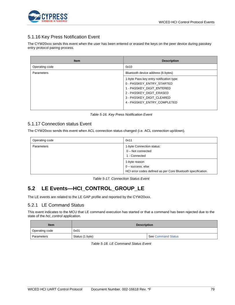
WICED HCI Control Protocol Events
WICED HCI UART Control Protocol Document Number. 002-16618 Rev. *F 79
5.1.16 Key Press Notification Event
The CYW20xxx sends this event when the user has been entered or erased the keys on the peer device during passkey entry protocol pairing process.
Item Description
Operating code 0x10
Parameters Bluetooth device address (6 bytes)
1-byte Pass key entry notification type:
0 - PASSKEY_ENTRY_STARTED
1 - PASSKEY_DIGIT_ENTERED
2 - PASSKEY_DIGIT_ERASED
3 - PASSKEY_DIGIT_CLEARED
4 - PASSKEY_ENTRY_COMPLETED
Table 5-16. Key Press Notification Event
5.1.17 Connection status Event
The CYW20xxx sends this event when ACL connection status changed (i.e. ACL connection up/down).
Operating code 0x11
Parameters 1-byte Connection status:
0 – Not connected
1 - Connected
1-byte reason
0 – success, else
HCI error codes defined as per Core Bluetooth specification.
Table 5-17. Connection Status Event
5.2 LE Events—HCI_CONTROL_GROUP_LE
The LE events are related to the LE GAP profile and reported by the CYW20xxx.
5.2.1 LE Command Status
This event indicates to the MCU that LE command execution has started or that a command has been rejected due to the state of the hci_control application.
Item Description
Operating code 0x01
Parameters Status (1 byte) See Command Status
Table 5-18. LE Command Status Event

WICED HCI Control Protocol Events
WICED HCI UART Control Protocol Document Number. 002-16618 Rev. *F 80
5.2.2 LE Scan Status
The hci_control application sends a Scan Status event when the CYW20xxx enters a new scanning state. A scanning state transition can be caused by a received LE Scan Command or internal application or stack logic.
Item Description
Operating code 0x02
Parameters Statea 0 No scan
1 High-duty-cycle scan
2 Low-duty-cycle scan
a. The high-duty-cycle and low-duty-cycle scan parameters for each state are defined in the wiced_bt_cfg.c file, which is included in every application.
Table 5-19. LE Scan Status Event
5.2.3 LE Advertisement Report
The hci_control application sends an LE Advertisement Report event when the CYW20xxx is scanning and it receives an advertisement or a scan response from a peer device.
Item Description
Operating code 0x03
Parameters Event type indicating the type of advertisement report (1 byte)
Address type indicating the Bluetooth address type (1 byte)
Bluetooth device address (6 bytes)
RSSI of the advertisement (1 byte)
Advertisement data (variable bytes)
Table 5-20. LE Advertisement Report Event
5.2.4 LE Advertisement State
The hci_control application sends an Advertisement State event when the CYW20xxx enters a new advertisement state. An advertisement state change can be caused by an Advertisement Command received from the MCU or by internal application or stack logic.
Item Description
Operating code 0x04
Parameters Statea 0 Not Discoverable
1 High-duty-cycle discoverable
2 Low-duty-cycle discoverable
a. The advertisement intervals and durations for each state are defined in the wiced_bt_cfg.c file, which is included in every application.
Table 5-21. LE Advertisement State Event
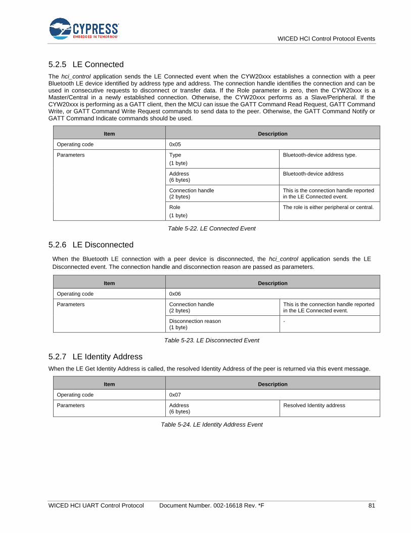
WICED HCI Control Protocol Events
WICED HCI UART Control Protocol Document Number. 002-16618 Rev. *F 81
5.2.5 LE Connected
The hci_control application sends the LE Connected event when the CYW20xxx establishes a connection with a peer Bluetooth LE device identified by address type and address. The connection handle identifies the connection and can be used in consecutive requests to disconnect or transfer data. If the Role parameter is zero, then the CYW20xxx is a Master/Central in a newly established connection. Otherwise, the CYW20xxx performs as a Slave/Peripheral. If the CYW20xxx is performing as a GATT client, then the MCU can issue the GATT Command Read Request, GATT Command Write, or GATT Command Write Request commands to send data to the peer. Otherwise, the GATT Command Notify or GATT Command Indicate commands should be used.
Item Description
Operating code 0x05
Parameters Type
(1 byte)
Bluetooth-device address type.
Address (6 bytes)
Bluetooth-device address
Connection handle (2 bytes)
This is the connection handle reported in the LE Connected event.
Role
(1 byte)
The role is either peripheral or central.
Table 5-22. LE Connected Event
5.2.6 LE Disconnected
When the Bluetooth LE connection with a peer device is disconnected, the hci_control application sends the LE
Disconnected event. The connection handle and disconnection reason are passed as parameters.
Item Description
Operating code 0x06
Parameters Connection handle (2 bytes)
This is the connection handle reported in the LE Connected event.
Disconnection reason (1 byte)
-
Table 5-23. LE Disconnected Event
5.2.7 LE Identity Address
When the LE Get Identity Address is called, the resolved Identity Address of the peer is returned via this event message.
Item Description
Operating code 0x07
Parameters Address (6 bytes)
Resolved Identity address
Table 5-24. LE Identity Address Event

WICED HCI Control Protocol Events
WICED HCI UART Control Protocol Document Number. 002-16618 Rev. *F 82
5.2.8 LE Peer MTU
When the CYW20xxx receives a Client MTU Request, this event will be passed to the MCU indicating the negotiated MTU size.
Item Description
Operating code 0x08
Parameters Connection handle (2 bytes)
This is the connection handle reported in the LE Connected event
MTU size (2 bytes)
Table 5-25. LE Peer MTU Event
5.2.9 LE Connection Parameters
When the CYW20xxx receives a connection update complete event from a peer device, this LE Connection Parameters event will be passed to the MCU indicating the negotiated connection parameters or error code reflected by the Status byte.
Item Description
Operating code 0x09
Parameters Status (1 byte)
0: Success, Else: Failure
Peer Address (6 bytes)
Connection Interval (2 bytes)
Connection Latency
(2 bytes)
Supervision Timeout
(2 bytes)
Table 5-26. LE Connection Parameters Event
5.3 GATT Events
The GATT events are related to the GATT profile and reported by the CYW20xxx.
5.3.1 GATT Command Status
This event indicates to the MCU that GATT command execution has started or that a command has been rejected due to the state of the hci_control application.
Item Description
Operating code 0x01
Parameters Status (1 byte)
See Command Status
Table 5-27. GATT Command Status Event
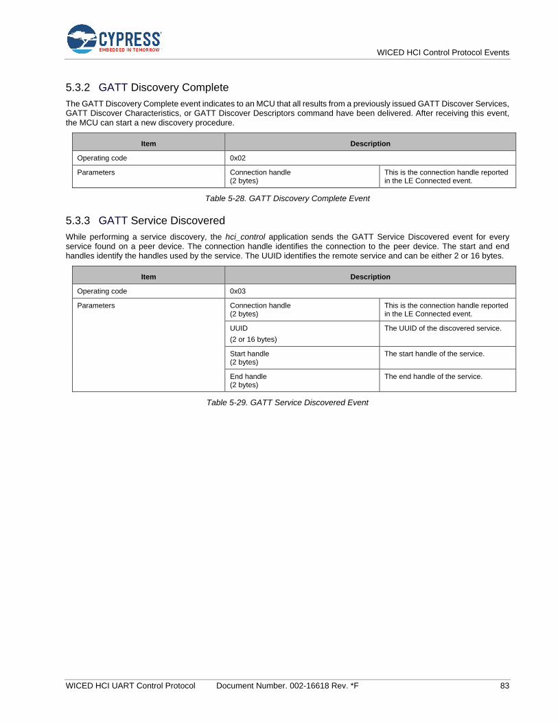
WICED HCI Control Protocol Events
WICED HCI UART Control Protocol Document Number. 002-16618 Rev. *F 83
5.3.2 GATT Discovery Complete
The GATT Discovery Complete event indicates to an MCU that all results from a previously issued GATT Discover Services, GATT Discover Characteristics, or GATT Discover Descriptors command have been delivered. After receiving this event, the MCU can start a new discovery procedure.
Item Description
Operating code 0x02
Parameters Connection handle (2 bytes)
This is the connection handle reported in the LE Connected event.
Table 5-28. GATT Discovery Complete Event
5.3.3 GATT Service Discovered
While performing a service discovery, the hci_control application sends the GATT Service Discovered event for every service found on a peer device. The connection handle identifies the connection to the peer device. The start and end handles identify the handles used by the service. The UUID identifies the remote service and can be either 2 or 16 bytes.
Item Description
Operating code 0x03
Parameters Connection handle (2 bytes)
This is the connection handle reported in the LE Connected event.
UUID
(2 or 16 bytes)
The UUID of the discovered service.
Start handle (2 bytes)
The start handle of the service.
End handle (2 bytes)
The end handle of the service.
Table 5-29. GATT Service Discovered Event

WICED HCI Control Protocol Events
WICED HCI UART Control Protocol Document Number. 002-16618 Rev. *F 84
5.3.4 GATT Characteristic Discovered
While performing a characteristic discovery, the hci_control application sends the GATT Characteristic Discovered event for every characteristic discovered on the peer device. The connection handle identifies the connection to the peer device. The value handle can be used by the MCU in consecutive GATT Read, GATT Write Command, GATT Write Request, GATT Notify, or GATT Indicate calls to send data to the peer. The UUID identifies the remote characteristic and can be either 2 or 16 bytes.
Item Description
Operating code 0x04
Parameters Connection handle (2 bytes)
This is the connection handle reported in the LE Connected event.
Characteristic handle (2 bytes)
-
UUID
(2 or 16 bytes)
The UUID of the characteristic found.
Characteristic properties
(1 byte)
A bit mask of the properties supported by the discovered characteristic.
Value handle (2 bytes)
The characteristic-value handle that can be used in consecutive reads and write.
Table 5-30. GATT Characteristic Discovered Event
5.3.5 GATT Descriptor Discovered
While performing a characteristic descriptor discovery, the hci_control application sends the GATT Descriptor Discovered event for every characteristic descriptor discovered on the peer device. The connection handle identifies the connection to the peer device. The handle can be used by the MCU in consecutive GATT Read or GATT Write Request commands to set or get a descriptor value. The UUID identifies the remote descriptor and can be either 2 or 16 bytes
Item Description
Operating code 0x05
Parameters Connection handle (2 bytes)
This is the connection handle reported in the LE Connected event.
UUID
(2 or 16 bytes)
The descriptor UUID.
Handle
(2 bytes)
The descriptor handle, which can be used in subsequent reads and writes.
Table 5-31. GATT Descriptor Discovered Event

WICED HCI Control Protocol Events
WICED HCI UART Control Protocol Document Number. 002-16618 Rev. *F 85
5.3.6 GATT Event Read Request
The GATT Event Read Request can be sent to the MCU to provide the value of the specific attribute. The connection handle identifies the connection to the peer device requesting the operation and the attribute handle identifies the attribute requested by the peer device. Upon receiving this request, the MCU should send the GATT Command Read Response (see GATT Command Read Response).
Item Description
Operating code 0x06
Parameters Connection handle (2 bytes)
This is the connection handle reported in the LE Connected event.
Attribute handle (2 bytes)
The attribute handle of the value being read.
Table 5-32. GATT Event Read Request
See Figure 4-4 for a message sequence example where the GATT Event Read Request is used.
5.3.7 GATT Event Read Response
The GATT Event Read Response indicates to the MCU that the execution of the GATT Command Read Request has completed. The event includes the received data. The connection handle identifies the connection to the peer device for which the read procedure has been performed.
Item Description
Operating code 0x07
Parameters Connection handle (2 bytes)
This is the connection handle reported in the LE Connected event.
Data
(variable bytes
-
Table 5-33. GATT Event Read Response
See Figure 4-3 and Figure 4-4 for message sequence examples where the GATT Event Read Response is used.
5.3.8 GATT Event Write Request
The GATT Event Write Request indicates to the MCU that a write request from a connected peer has been received. The connection handle identifies the connection of the peer device that issued the write request and the attribute handle identifies the characteristic to be written.
The CYW20xxx application can be designed to wait for the GATT Command Write Response (see GATT Command Write Response) or to reply automatically to indicate the success of the write operation to the peer. Waiting for the GATT Command Write Response is required when the MCU needs to be able to reject peer write attempts.
Item Description
Operating code 0x08
Parameters Connection handle (2 bytes)
This is the connection handle reported in the LE Connected event.
Attribute handle (2 bytes)
The attribute handle of the value being written.
Data
(variable bytes)
-
Table 5-34. GATT Event Write Request
See Figure 4-7 for a message sequence example where the GATT Event Write Request is used.
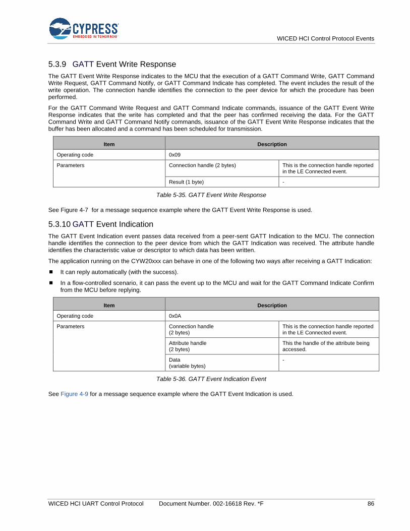
WICED HCI Control Protocol Events
WICED HCI UART Control Protocol Document Number. 002-16618 Rev. *F 86
5.3.9 GATT Event Write Response
The GATT Event Write Response indicates to the MCU that the execution of a GATT Command Write, GATT Command Write Request, GATT Command Notify, or GATT Command Indicate has completed. The event includes the result of the write operation. The connection handle identifies the connection to the peer device for which the procedure has been performed.
For the GATT Command Write Request and GATT Command Indicate commands, issuance of the GATT Event Write Response indicates that the write has completed and that the peer has confirmed receiving the data. For the GATT Command Write and GATT Command Notify commands, issuance of the GATT Event Write Response indicates that the buffer has been allocated and a command has been scheduled for transmission.
Item Description
Operating code 0x09
Parameters Connection handle (2 bytes) This is the connection handle reported in the LE Connected event.
Result (1 byte) -
Table 5-35. GATT Event Write Response
See Figure 4-7 for a message sequence example where the GATT Event Write Response is used.
5.3.10 GATT Event Indication
The GATT Event Indication event passes data received from a peer-sent GATT Indication to the MCU. The connection handle identifies the connection to the peer device from which the GATT Indication was received. The attribute handle identifies the characteristic value or descriptor to which data has been written.
The application running on the CYW20xxx can behave in one of the following two ways after receiving a GATT Indication:
It can reply automatically (with the success).
In a flow-controlled scenario, it can pass the event up to the MCU and wait for the GATT Command Indicate Confirm from the MCU before replying.
Item Description
Operating code 0x0A
Parameters Connection handle (2 bytes)
This is the connection handle reported in the LE Connected event.
Attribute handle (2 bytes)
This the handle of the attribute being accessed.
Data (variable bytes)
-
Table 5-36. GATT Event Indication Event
See Figure 4-9 for a message sequence example where the GATT Event Indication is used.
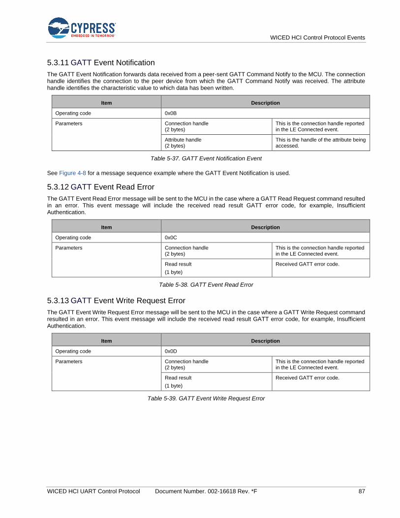
WICED HCI Control Protocol Events
WICED HCI UART Control Protocol Document Number. 002-16618 Rev. *F 87
5.3.11 GATT Event Notification
The GATT Event Notification forwards data received from a peer-sent GATT Command Notify to the MCU. The connection handle identifies the connection to the peer device from which the GATT Command Notify was received. The attribute handle identifies the characteristic value to which data has been written.
Item Description
Operating code 0x0B
Parameters Connection handle (2 bytes)
This is the connection handle reported in the LE Connected event.
Attribute handle (2 bytes)
This is the handle of the attribute being accessed.
Table 5-37. GATT Event Notification Event
See Figure 4-8 for a message sequence example where the GATT Event Notification is used.
5.3.12 GATT Event Read Error
The GATT Event Read Error message will be sent to the MCU in the case where a GATT Read Request command resulted in an error. This event message will include the received read result GATT error code, for example, Insufficient Authentication.
Item Description
Operating code 0x0C
Parameters Connection handle (2 bytes)
This is the connection handle reported in the LE Connected event.
Read result
(1 byte)
Received GATT error code.
Table 5-38. GATT Event Read Error
5.3.13 GATT Event Write Request Error
The GATT Event Write Request Error message will be sent to the MCU in the case where a GATT Write Request command resulted in an error. This event message will include the received read result GATT error code, for example, Insufficient Authentication.
Item Description
Operating code 0x0D
Parameters Connection handle (2 bytes)
This is the connection handle reported in the LE Connected event.
Read result
(1 byte)
Received GATT error code.
Table 5-39. GATT Event Write Request Error

WICED HCI Control Protocol Events
WICED HCI UART Control Protocol Document Number. 002-16618 Rev. *F 88
5.4 HF Events: HCI_CONTROL_GROUP_HF
These events sent by the CYW20xxx pertain to the functionality of the Hands-Free profile.
5.4.1 HF Open
This event is sent when an RFCOMM connection is established with an AG. At this point, the Service Level Connection (SLC) is still not established, so commands cannot yet be sent. The Bluetooth device address and connection handle are passed as parameters. The connection handle can be used by the MCU to send commands or to identify a peer device that caused the event.
Item Description
Operating code 0x01
Parameters Connection handle (2 bytes)
Bluetooth device address of the AG (6 bytes)
Status (1 byte)
Table 5-40. HF Open Event
5.4.2 HF Close
This event is sent when an RFCOMM connection with an AG is closed.
Item Description
Operating code 0x02
Parameters Connection handle (2 bytes)
Table 5-41. HF Close Event
5.4.3 HF Connected
This event is sent when the hands-free device and the AG have completed the protocol exchange necessary to establish
an SLC. At this point, the application can send any commands to the CYW20xxx.
Item Description
Operating code 0x03
Parameters Connection handle (2 bytes)
32-bit mask of AG supported features
Table 5-42. HF Connected Event
5.4.4 HF Audio Open
This event is sent when an audio connection with an AG is opened.
Item Description
Operating code 0x04
Parameters Connection handle (2 bytes)
Table 5-43. HF Audio Open Event

WICED HCI Control Protocol Events
WICED HCI UART Control Protocol Document Number. 002-16618 Rev. *F 89
5.4.5 HF Audio Close
This event is sent when an audio connection with an AG is closed.
Item Description
Operating code 0x05
Parameters Connection handle (2 bytes)
Table 5-44. HF Audio Close Event
5.4.6 HF Audio Connection Request
This event is sent to the MCU on receiving an audio connection request from the AG. The MCU shall use the HF Accept/Reject Audio Connection command to accept/reject the connection request.
Item Description
Operating code 0x06
Parameters Bluetooth device address of the AG (6 bytes)
SCO Index (2 bytes)
Table 5-45. HF Audio Connection Request Event
5.4.7 HF Response
The HF Response events are sent when a response is received from the AG for a command sent by the application.
Item Description
Operating code See Table 5-47
Parameters Connection handle (2 bytes)
Numeric value (2 bytes)
Optional supporting character string
Table 5-46. HF Response Event Format
Table 5-47 shows various available values for the operating code, numeric value, and optional string parameters of Table 5-46
Operating Code Numeric Value Optional String
Code Description
0x20 OK response Command index of last command
-
0x21 Error response Command index of last command
-
0x22 Extended error response Command index of last command
Error code
0x23 Incoming call - -
0x24 Speaker gain 0–15 -
0x25 Microphone gain 0–15 -
0x26 Incoming call waiting - The calling party’s number and number type. For example: “nnnnn, 128”
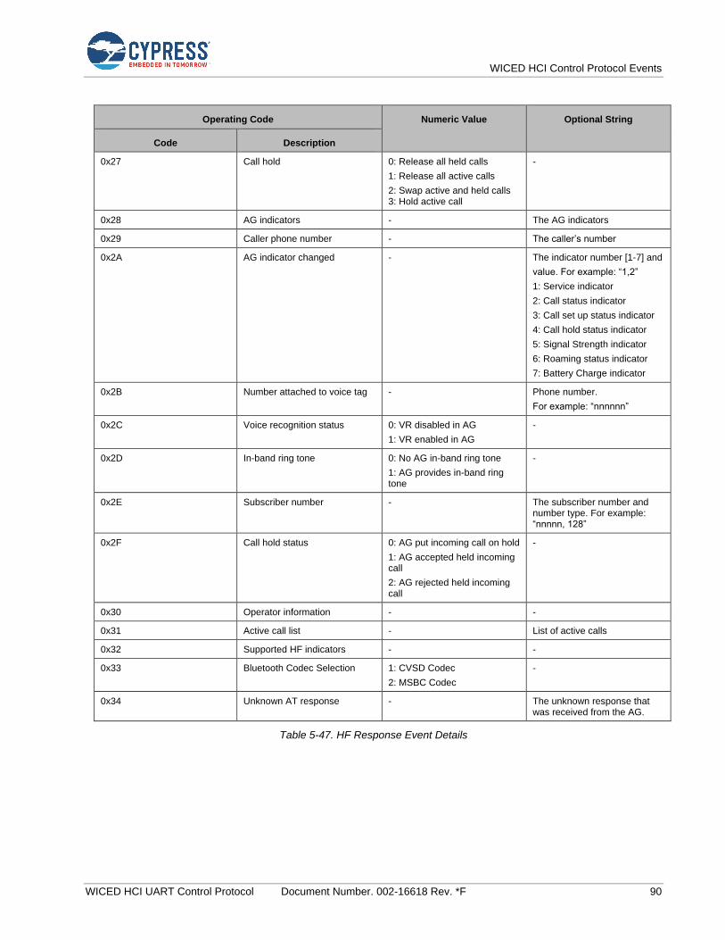
WICED HCI Control Protocol Events
WICED HCI UART Control Protocol Document Number. 002-16618 Rev. *F 90
Operating Code Numeric Value Optional String
Code Description
0x27 Call hold 0: Release all held calls
1: Release all active calls
2: Swap active and held calls 3: Hold active call
-
0x28 AG indicators - The AG indicators
0x29 Caller phone number - The caller’s number
0x2A AG indicator changed - The indicator number [1-7] and
value. For example: “1,2”
1: Service indicator
2: Call status indicator
3: Call set up status indicator
4: Call hold status indicator
5: Signal Strength indicator
6: Roaming status indicator
7: Battery Charge indicator
0x2B Number attached to voice tag - Phone number.
For example: “nnnnnn”
0x2C Voice recognition status 0: VR disabled in AG
1: VR enabled in AG
-
0x2D In-band ring tone 0: No AG in-band ring tone
1: AG provides in-band ring tone
-
0x2E Subscriber number - The subscriber number and number type. For example: “nnnnn, 128”
0x2F Call hold status 0: AG put incoming call on hold
1: AG accepted held incoming call
2: AG rejected held incoming call
-
0x30 Operator information - -
0x31 Active call list - List of active calls
0x32 Supported HF indicators - -
0x33 Bluetooth Codec Selection 1: CVSD Codec
2: MSBC Codec
-
0x34 Unknown AT response - The unknown response that was received from the AG.
Table 5-47. HF Response Event Details

WICED HCI Control Protocol Events
WICED HCI UART Control Protocol Document Number. 002-16618 Rev. *F 91
5.5 SPP Events— HCI_CONTROL_GROUP_SPP
These events sent by the CYW20xxx pertain to the functionality of the Serial Port Profile (SPP).
5.5.1 SPP Connected
This event is sent when an SPP connection has been established with a peer device. The Bluetooth device address and connection handle are passed as parameters. The connection handle can be used by the MCU for future commands to send commands or data and to identify a peer device that has sent data.
Item Description
Operating code 0x01
Parameters Bluetooth device address (6 bytes)
Connection handle (2 bytes)
Table 5-48. SPP Connected Event
5.5.2 SPP Service Not Found
This event is sent when a CYW20xxx is able to connect to a peer device and perform SDP discovery, but the SPP service
is not found.
Item Description
Operating code 0x02
Parameters -
Table 5-49. SPP Service Not Found Event
5.5.3 SPP Connection Failed
A CYW20xxx sends this event when a connection attempt requested by an MCU is unsuccessful.
Item Description
Operating code 0x03
Parameters -
Table 5-50. SPP Connection Failed Event
5.5.4 SPP Disconnected
This event is sent when an SPP connection has been dropped.
Item Description
Operating code 0x04
Parameters Connection handle (2 bytes)
Table 5-51. SPP Disconnected Event
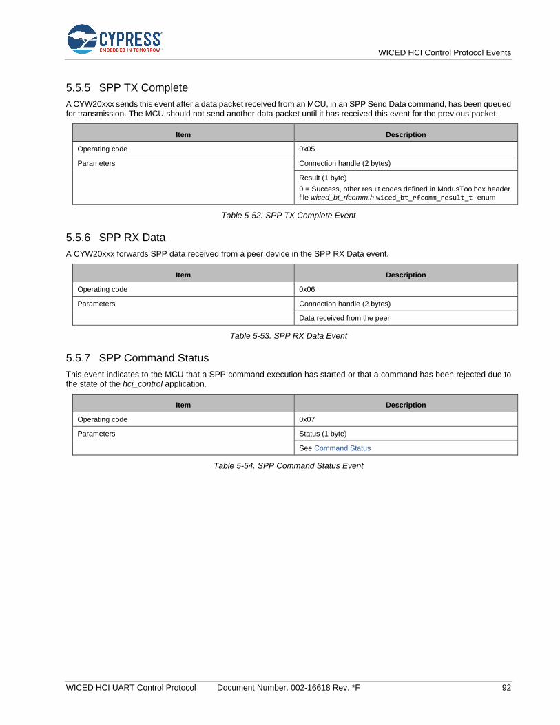
WICED HCI Control Protocol Events
WICED HCI UART Control Protocol Document Number. 002-16618 Rev. *F 92
5.5.5 SPP TX Complete
A CYW20xxx sends this event after a data packet received from an MCU, in an SPP Send Data command, has been queued for transmission. The MCU should not send another data packet until it has received this event for the previous packet.
Item Description
Operating code 0x05
Parameters Connection handle (2 bytes)
Result (1 byte)
0 = Success, other result codes defined in ModusToolbox header file wiced_bt_rfcomm.h wiced_bt_rfcomm_result_t enum
Table 5-52. SPP TX Complete Event
5.5.6 SPP RX Data
A CYW20xxx forwards SPP data received from a peer device in the SPP RX Data event.
Item Description
Operating code 0x06
Parameters Connection handle (2 bytes)
Data received from the peer
Table 5-53. SPP RX Data Event
5.5.7 SPP Command Status
This event indicates to the MCU that a SPP command execution has started or that a command has been rejected due to the state of the hci_control application.
Item Description
Operating code 0x07
Parameters Status (1 byte)
See Command Status
Table 5-54. SPP Command Status Event
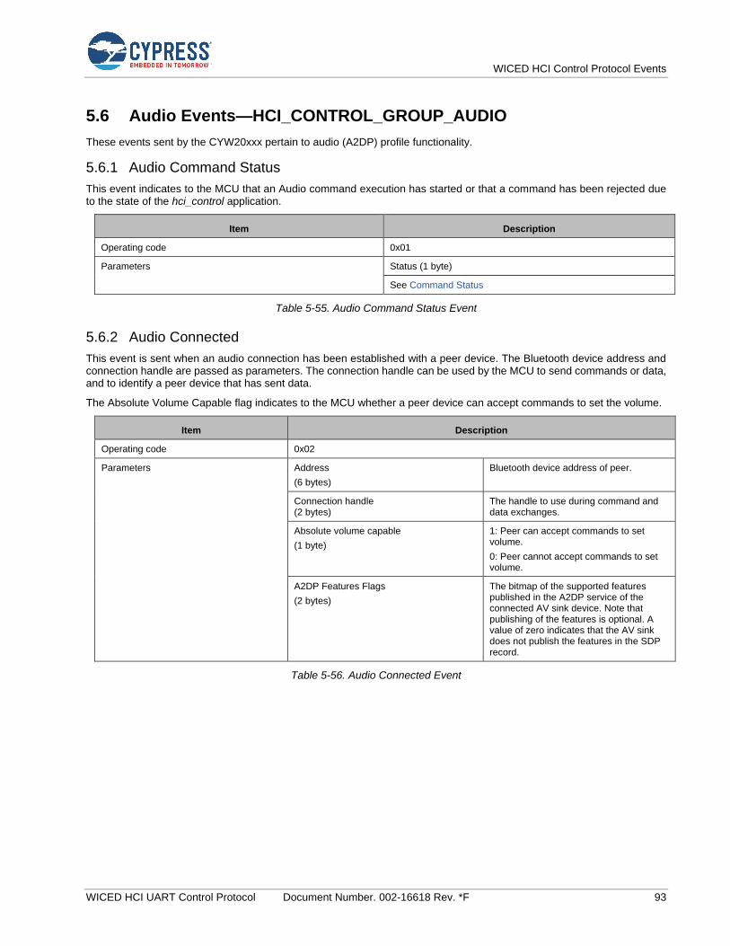
WICED HCI Control Protocol Events
WICED HCI UART Control Protocol Document Number. 002-16618 Rev. *F 93
5.6 Audio Events—HCI_CONTROL_GROUP_AUDIO
These events sent by the CYW20xxx pertain to audio (A2DP) profile functionality.
5.6.1 Audio Command Status
This event indicates to the MCU that an Audio command execution has started or that a command has been rejected due to the state of the hci_control application.
Item Description
Operating code 0x01
Parameters Status (1 byte)
See Command Status
Table 5-55. Audio Command Status Event
5.6.2 Audio Connected
This event is sent when an audio connection has been established with a peer device. The Bluetooth device address and connection handle are passed as parameters. The connection handle can be used by the MCU to send commands or data, and to identify a peer device that has sent data.
The Absolute Volume Capable flag indicates to the MCU whether a peer device can accept commands to set the volume.
Item Description
Operating code 0x02
Parameters Address
(6 bytes)
Bluetooth device address of peer.
Connection handle (2 bytes)
The handle to use during command and data exchanges.
Absolute volume capable
(1 byte)
1: Peer can accept commands to set volume.
0: Peer cannot accept commands to set volume.
A2DP Features Flags
(2 bytes)
The bitmap of the supported features published in the A2DP service of the connected AV sink device. Note that publishing of the features is optional. A value of zero indicates that the AV sink does not publish the features in the SDP record.
Table 5-56. Audio Connected Event
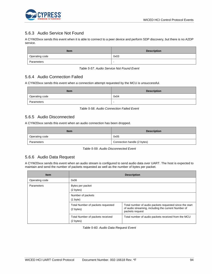
WICED HCI Control Protocol Events
WICED HCI UART Control Protocol Document Number. 002-16618 Rev. *F 94
5.6.3 Audio Service Not Found
A CYW20xxx sends this event when it is able to connect to a peer device and perform SDP discovery, but there is no A2DP service.
Item Description
Operating code 0x03
Parameters -
Table 5-57. Audio Service Not Found Event
5.6.4 Audio Connection Failed
A CYW20xxx sends this event when a connection attempt requested by the MCU is unsuccessful.
Item Description
Operating code 0x04
Parameters -
Table 5-58. Audio Connection Failed Event
5.6.5 Audio Disconnected
A CYW20xxx sends this event when an audio connection has been dropped.
Item Description
Operating code 0x05
Parameters Connection handle (2 bytes)
Table 5-59. Audio Disconnected Event
5.6.6 Audio Data Request
A CYW20xxx sends this event when an audio stream is configured to send audio data over UART. The host is expected to maintain and send the number of packets requested as well as the number of bytes per packet.
Item Description
Operating code 0x06
Parameters Bytes per packet
(2 bytes)
Number of packets
(1 byte)
Total Number of packets requested
(2 bytes)
Total number of audio packets requested since the start of audio streaming, including the current Number of packets request
Total Number of packets received
(2 bytes)
Total number of audio packets received from the MCU
Table 5-60. Audio Data Request Event
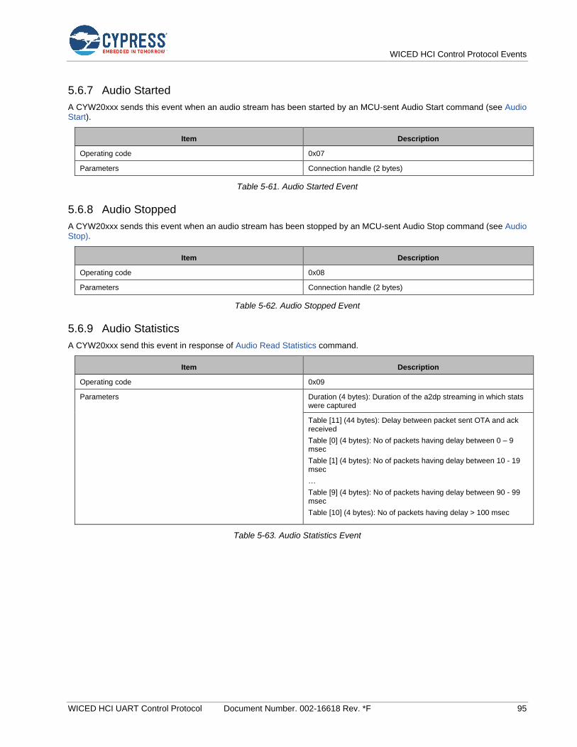
WICED HCI Control Protocol Events
WICED HCI UART Control Protocol Document Number. 002-16618 Rev. *F 95
5.6.7 Audio Started
A CYW20xxx sends this event when an audio stream has been started by an MCU-sent Audio Start command (see Audio Start).
Item Description
Operating code 0x07
Parameters Connection handle (2 bytes)
Table 5-61. Audio Started Event
5.6.8 Audio Stopped
A CYW20xxx sends this event when an audio stream has been stopped by an MCU-sent Audio Stop command (see Audio Stop).
Item Description
Operating code 0x08
Parameters Connection handle (2 bytes)
Table 5-62. Audio Stopped Event
5.6.9 Audio Statistics
A CYW20xxx send this event in response of Audio Read Statistics command.
Item Description
Operating code 0x09
Parameters Duration (4 bytes): Duration of the a2dp streaming in which stats were captured
Table [11] (44 bytes): Delay between packet sent OTA and ack received
Table [0] (4 bytes): No of packets having delay between 0 – 9 msec
Table [1] (4 bytes): No of packets having delay between 10 - 19 msec
…
Table [9] (4 bytes): No of packets having delay between 90 - 99 msec
Table [10] (4 bytes): No of packets having delay > 100 msec
Table 5-63. Audio Statistics Event

WICED HCI Control Protocol Events
WICED HCI UART Control Protocol Document Number. 002-16618 Rev. *F 96
5.7 AV Remote Control Controller Events: HCI_CONTROL_GROUP_AVRC_CONTROLLER
5.7.1 AVRC Controller Connected
A CYW20xxx sends the AVRC Connected event to an MCU when a peer device establishes an AVRC connection or after a connection requested by an AVRC Connect command has been successfully established.
Item Description
Operating code 0x01
Parameters bd_addr (6 bytes)
Bluetooth address of the connected player.
Status (1 byte)
Status of the connection establishment event. If 0, then the connection has been established successfully.
Session handle (2 bytes)
The session handle as reported in the AVRC Connected event.
Table 5-64. AVRC Controller Connected Event
5.7.2 AVRC Controller Disconnected
A CYW20xxx sends the AVRC Disconnected event to an MCU to indicate that the AVRC connection has been terminated.
Item Description
Operating code 0x02
Parameters Session handle (2 bytes)
The session handle as reported in the AVRC Connected event.
Table 5-65. AVRC Controller Disconnected Event
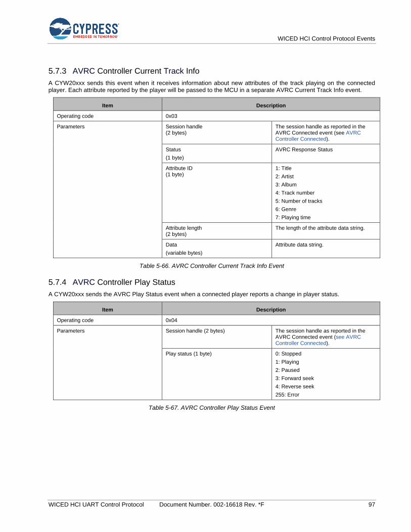
WICED HCI Control Protocol Events
WICED HCI UART Control Protocol Document Number. 002-16618 Rev. *F 97
5.7.3 AVRC Controller Current Track Info
A CYW20xxx sends this event when it receives information about new attributes of the track playing on the connected player. Each attribute reported by the player will be passed to the MCU in a separate AVRC Current Track Info event.
Item Description
Operating code 0x03
Parameters Session handle (2 bytes)
The session handle as reported in the AVRC Connected event (see AVRC Controller Connected).
Status
(1 byte)
AVRC Response Status
Attribute ID (1 byte)
1: Title
2: Artist
3: Album
4: Track number
5: Number of tracks
6: Genre
7: Playing time
Attribute length (2 bytes)
The length of the attribute data string.
Data
(variable bytes)
Attribute data string.
Table 5-66. AVRC Controller Current Track Info Event
5.7.4 AVRC Controller Play Status
A CYW20xxx sends the AVRC Play Status event when a connected player reports a change in player status.
Item Description
Operating code 0x04
Parameters Session handle (2 bytes) The session handle as reported in the AVRC Connected event (see AVRC Controller Connected).
Play status (1 byte) 0: Stopped
1: Playing
2: Paused
3: Forward seek
4: Reverse seek
255: Error
Table 5-67. AVRC Controller Play Status Event
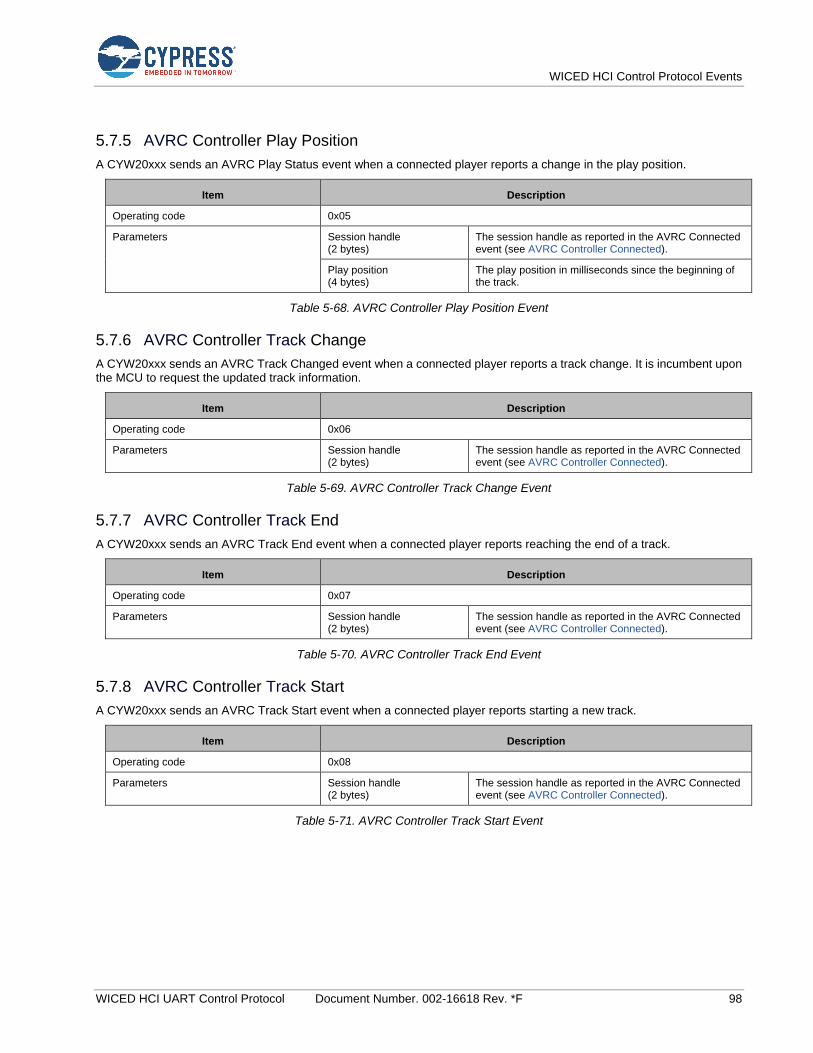
WICED HCI Control Protocol Events
WICED HCI UART Control Protocol Document Number. 002-16618 Rev. *F 98
5.7.5 AVRC Controller Play Position
A CYW20xxx sends an AVRC Play Status event when a connected player reports a change in the play position.
Item Description
Operating code 0x05
Parameters Session handle (2 bytes)
The session handle as reported in the AVRC Connected event (see AVRC Controller Connected).
Play position (4 bytes)
The play position in milliseconds since the beginning of the track.
Table 5-68. AVRC Controller Play Position Event
5.7.6 AVRC Controller Track Change
A CYW20xxx sends an AVRC Track Changed event when a connected player reports a track change. It is incumbent upon the MCU to request the updated track information.
Item Description
Operating code 0x06
Parameters Session handle (2 bytes)
The session handle as reported in the AVRC Connected event (see AVRC Controller Connected).
Table 5-69. AVRC Controller Track Change Event
5.7.7 AVRC Controller Track End
A CYW20xxx sends an AVRC Track End event when a connected player reports reaching the end of a track.
Item Description
Operating code 0x07
Parameters Session handle (2 bytes)
The session handle as reported in the AVRC Connected event (see AVRC Controller Connected).
Table 5-70. AVRC Controller Track End Event
5.7.8 AVRC Controller Track Start
A CYW20xxx sends an AVRC Track Start event when a connected player reports starting a new track.
Item Description
Operating code 0x08
Parameters Session handle (2 bytes)
The session handle as reported in the AVRC Connected event (see AVRC Controller Connected).
Table 5-71. AVRC Controller Track Start Event
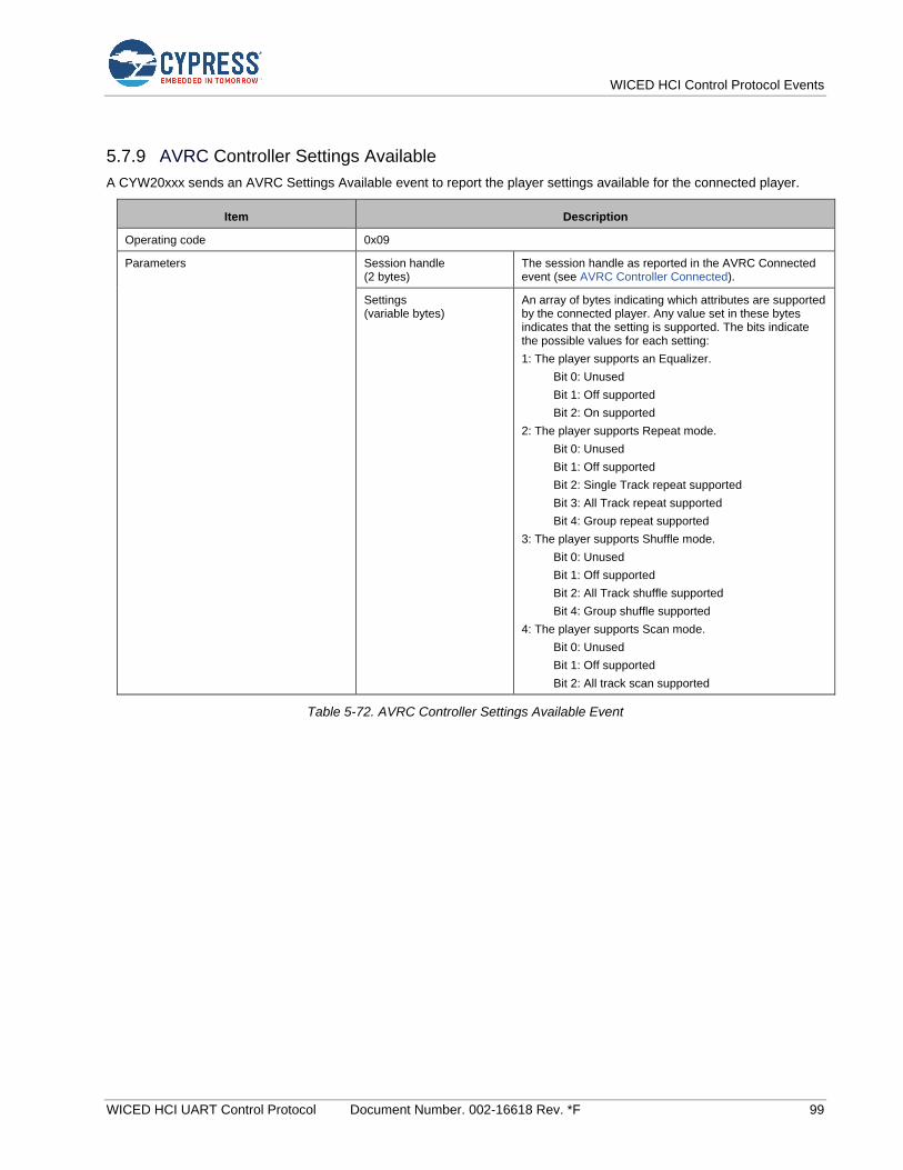
WICED HCI Control Protocol Events
WICED HCI UART Control Protocol Document Number. 002-16618 Rev. *F 99
5.7.9 AVRC Controller Settings Available
A CYW20xxx sends an AVRC Settings Available event to report the player settings available for the connected player.
Item Description
Operating code 0x09
Parameters Session handle (2 bytes)
The session handle as reported in the AVRC Connected event (see AVRC Controller Connected).
Settings (variable bytes)
An array of bytes indicating which attributes are supported by the connected player. Any value set in these bytes indicates that the setting is supported. The bits indicate the possible values for each setting:
1: The player supports an Equalizer.
Bit 0: Unused
Bit 1: Off supported
Bit 2: On supported
2: The player supports Repeat mode.
Bit 0: Unused
Bit 1: Off supported
Bit 2: Single Track repeat supported
Bit 3: All Track repeat supported
Bit 4: Group repeat supported
3: The player supports Shuffle mode.
Bit 0: Unused
Bit 1: Off supported
Bit 2: All Track shuffle supported
Bit 4: Group shuffle supported
4: The player supports Scan mode.
Bit 0: Unused
Bit 1: Off supported
Bit 2: All track scan supported
Table 5-72. AVRC Controller Settings Available Event

WICED HCI Control Protocol Events
WICED HCI UART Control Protocol Document Number. 002-16618 Rev. *F 100
5.7.10 AVRC Controller Setting Change
A CYW20xxx sends an AVRC Setting Change event to report the initial value or a settings change on a connected player.
Item Description
Operating code 0x0A
Parameters Session handle (2 bytes)
The session handle as reported in the AVRC Connected event (see AVRC Controller Connected).
Number of Settings (1 byte)
Number of ID-Value Pairs
Setting ID (1 byte)
The following values indicate the ID of the player setting:
1: Equalizer.
2: Repeat mode.
3: Shuffle mode.
4: Scan mode.
Setting value (1 byte)
For ID = 1 (Equalizer):
1: On
2: Off
For ID = 2 (Repeat mode):
1: Off
2: Repeat a single track
3: Repeat all tracks
4: Repeat a group of tracks
For ID = 3 (Shuffle mode):
1: Off
2: Shuffle all tracks
3: Shuffle a group of tracks
For ID = 4 (Scan mode):
1: Off
2: Scan all tracks
3: Scan a group of tracks
Table 5-73. AVRC Controller Setting Change Event
5.7.11 AVRC Controller Player Change
A CYW20xxx sends an AVRC Player change event to report a change in the named connected player.
Item Description
Operating code 0x0B
Parameters Name (n bytes). Character string that identifies the player by name.
Table 5-74. AVRC Controller Player Change Event

WICED HCI Control Protocol Events
WICED HCI UART Control Protocol Document Number. 002-16618 Rev. *F 101
5.7.12 AVRC Controller Command Status
This event indicates to the MCU that an AVRC command execution has started or that a command has been rejected due to the state of the hci_control application.
Item Description
Operating code 0xFF
Parameters Status (1 byte). See Command Status.
Table 5-75. AVRC Controller Command Status Event
5.8 AV Remote Control Target Events: HCI_CONTROL_GROUP_AVRC_TARGET
5.8.1 AVRC Target Connected
A CYW20xxx device sends the AVRC Connected event to an MCU when a peer device establishes an AVRC connection or after a connection requested by an AVRC Connect command has been successfully established.
Item Description
Operating code 0x01
Parameters bd_addr
(6 bytes).
Bluetooth address of the connected player.
Session handle (2 bytes)
The session handle as reported in the AVRC Connected event.
Table 5-76. AVRC Target Connected Event
5.8.2 AVRC Target Disconnected
A CYW20xxx sends the AVRC Disconnected event to an MCU to indicate that the AVRC connection has been terminated.
Item Description
Operating code 0x02
Parameters Session handle
(2 bytes).
The session handle as reported in the AVRC Connected event.
Table 5-77. AVRC Target Disconnected Event
5.8.3 AVRC Target Play
The CYW20xxx sends this event to the MCU when a play command is received from a connected AVRC controller.
Item Description
Operating code 0x03
Parameters Connection handle (2 bytes)
Table 5-78. AVRC Target Play Event
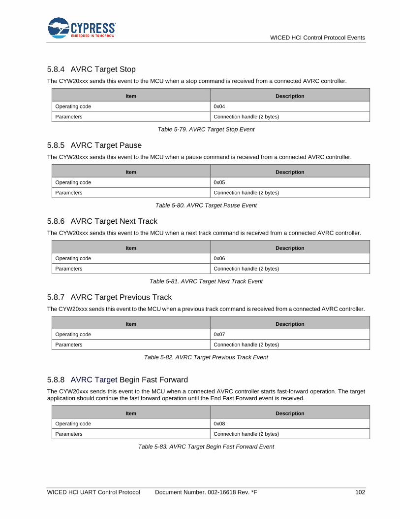
WICED HCI Control Protocol Events
WICED HCI UART Control Protocol Document Number. 002-16618 Rev. *F 102
5.8.4 AVRC Target Stop
The CYW20xxx sends this event to the MCU when a stop command is received from a connected AVRC controller.
Item Description
Operating code 0x04
Parameters Connection handle (2 bytes)
Table 5-79. AVRC Target Stop Event
5.8.5 AVRC Target Pause
The CYW20xxx sends this event to the MCU when a pause command is received from a connected AVRC controller.
Item Description
Operating code 0x05
Parameters Connection handle (2 bytes)
Table 5-80. AVRC Target Pause Event
5.8.6 AVRC Target Next Track
The CYW20xxx sends this event to the MCU when a next track command is received from a connected AVRC controller.
Item Description
Operating code 0x06
Parameters Connection handle (2 bytes)
Table 5-81. AVRC Target Next Track Event
5.8.7 AVRC Target Previous Track
The CYW20xxx sends this event to the MCU when a previous track command is received from a connected AVRC controller.
Item Description
Operating code 0x07
Parameters Connection handle (2 bytes)
Table 5-82. AVRC Target Previous Track Event
5.8.8 AVRC Target Begin Fast Forward
The CYW20xxx sends this event to the MCU when a connected AVRC controller starts fast-forward operation. The target application should continue the fast forward operation until the End Fast Forward event is received.
Item Description
Operating code 0x08
Parameters Connection handle (2 bytes)
Table 5-83. AVRC Target Begin Fast Forward Event
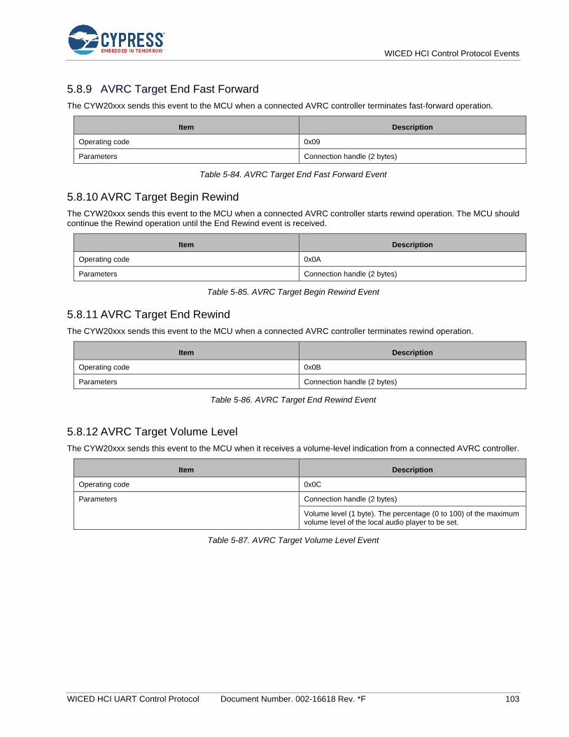
WICED HCI Control Protocol Events
WICED HCI UART Control Protocol Document Number. 002-16618 Rev. *F 103
5.8.9 AVRC Target End Fast Forward
The CYW20xxx sends this event to the MCU when a connected AVRC controller terminates fast-forward operation.
Item Description
Operating code 0x09
Parameters Connection handle (2 bytes)
Table 5-84. AVRC Target End Fast Forward Event
5.8.10 AVRC Target Begin Rewind
The CYW20xxx sends this event to the MCU when a connected AVRC controller starts rewind operation. The MCU should continue the Rewind operation until the End Rewind event is received.
Item Description
Operating code 0x0A
Parameters Connection handle (2 bytes)
Table 5-85. AVRC Target Begin Rewind Event
5.8.11 AVRC Target End Rewind
The CYW20xxx sends this event to the MCU when a connected AVRC controller terminates rewind operation.
Item Description
Operating code 0x0B
Parameters Connection handle (2 bytes)
Table 5-86. AVRC Target End Rewind Event
5.8.12 AVRC Target Volume Level
The CYW20xxx sends this event to the MCU when it receives a volume-level indication from a connected AVRC controller.
Item Description
Operating code 0x0C
Parameters Connection handle (2 bytes)
Volume level (1 byte). The percentage (0 to 100) of the maximum volume level of the local audio player to be set.
Table 5-87. AVRC Target Volume Level Event
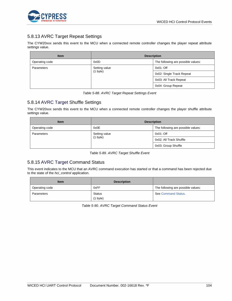
WICED HCI Control Protocol Events
WICED HCI UART Control Protocol Document Number. 002-16618 Rev. *F 104
5.8.13 AVRC Target Repeat Settings
The CYW20xxx sends this event to the MCU when a connected remote controller changes the player repeat attribute settings value.
Item Description
Operating code 0x0D The following are possible values:
Parameters Setting value (1 byte)
0x01: Off
0x02: Single Track Repeat
0x03: All Track Repeat
0x04: Group Repeat
Table 5-88. AVRC Target Repeat Settings Event
5.8.14 AVRC Target Shuffle Settings
The CYW20xxx sends this event to the MCU when a connected remote controller changes the player shuffle attribute settings value.
Item Description
Operating code 0x0E The following are possible values:
Parameters Setting value (1 byte)
0x01: Off
0x02: All Track Shuffle
0x03: Group Shuffle
Table 5-89. AVRC Target Shuffle Event
5.8.15 AVRC Target Command Status
This event indicates to the MCU that an AVRC command execution has started or that a command has been rejected due to the state of the hci_control application.
Item Description
Operating code 0xFF The following are possible values:
Parameters Status
(1 byte)
See Command Status.
Table 5-90. AVRC Target Command Status Event
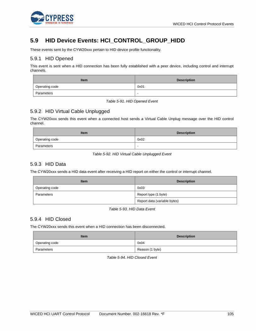
WICED HCI Control Protocol Events
WICED HCI UART Control Protocol Document Number. 002-16618 Rev. *F 105
5.9 HID Device Events: HCI_CONTROL_GROUP_HIDD
These events sent by the CYW20xxx pertain to HID device profile functionality.
5.9.1 HID Opened
This event is sent when a HID connection has been fully established with a peer device, including control and interrupt channels.
Item Description
Operating code 0x01
Parameters -
Table 5-91. HID Opened Event
5.9.2 HID Virtual Cable Unplugged
The CYW20xxx sends this event when a connected host sends a Virtual Cable Unplug message over the HID control channel.
Item Description
Operating code 0x02
Parameters -
Table 5-92. HID Virtual Cable Unplugged Event
5.9.3 HID Data
The CYW20xxx sends a HID data event after receiving a HID report on either the control or interrupt channel.
Item Description
Operating code 0x03
Parameters Report type (1 byte)
Report data (variable bytes)
Table 5-93. HID Data Event
5.9.4 HID Closed
The CYW20xxx sends this event when a HID connection has been disconnected.
Item Description
Operating code 0x04
Parameters Reason (1 byte)
Table 5-94. HID Closed Event
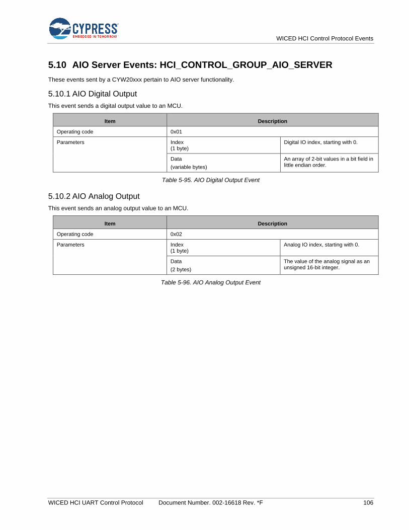
WICED HCI Control Protocol Events
WICED HCI UART Control Protocol Document Number. 002-16618 Rev. *F 106
5.10 AIO Server Events: HCI_CONTROL_GROUP_AIO_SERVER
These events sent by a CYW20xxx pertain to AIO server functionality.
5.10.1 AIO Digital Output
This event sends a digital output value to an MCU.
Item Description
Operating code 0x01
Parameters Index (1 byte)
Digital IO index, starting with 0.
Data
(variable bytes)
An array of 2-bit values in a bit field in little endian order.
Table 5-95. AIO Digital Output Event
5.10.2 AIO Analog Output
This event sends an analog output value to an MCU.
Item Description
Operating code 0x02
Parameters Index (1 byte)
Analog IO index, starting with 0.
Data
(2 bytes)
The value of the analog signal as an unsigned 16-bit integer.
Table 5-96. AIO Analog Output Event

WICED HCI Control Protocol Events
WICED HCI UART Control Protocol Document Number. 002-16618 Rev. *F 107
5.11 AIO Client Events: HCI_CONTROL_GROUP_AIO_CLIENT
These events sent by a CYW20xxx pertain to AIO client functionality.
5.11.1 AIO Command Status
This event indicates to an MCU that AIO command execution has started or that a command was rejected due to the state of the application.
Item Description
Operating code 0x01
Parameters Status (1 byte) 0: Command execution has started.
1: Command rejected because the previous command is still executing.
2: Connect command rejected; the specified device is already connected.
3: Disconnect command rejected because the connection is down.
4: Characteristic is not found.
5: Characteristic Descriptor is not found.
6: Invalid parameters passed in the command
Table 5-97. AIO Command Status Event
5.11.2 AIO Connected
This event instructs an MCU that a connection with an AIO server had been created.
Item Description
Operating code 0x02
Parameters Device address (6 bytes)
Table 5-98. AIO Connected Event
5.11.3 AIO Read Response
This event sends a read response to an MCU.
Item Description
Operating code 0x03
Parameters Status (1 byte)
0: Success.
2: Read not permitted.
Data
(variable bytes)
An unsigned 16-bit integer for analog IO or an array of 2-bit values in a bit field for digital IO.
Table 5-99. AIO Read Response Event
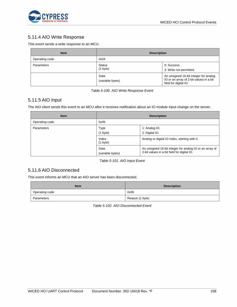
WICED HCI Control Protocol Events
WICED HCI UART Control Protocol Document Number. 002-16618 Rev. *F 108
5.11.4 AIO Write Response
This event sends a write response to an MCU.
Item Description
Operating code 0x04
Parameters Status (1 byte)
0: Success.
3: Write not permitted.
Data
(variable bytes)
An unsigned 16-bit integer for analog IO or an array of 2-bit values in a bit field for digital IO.
Table 5-100. AIO Write Response Event
5.11.5 AIO Input
The AIO client sends this event to an MCU after it receives notification about an IO module input change on the server.
Item Description
Operating code 0x05
Parameters Type
(1 byte)
1: Analog IO.
2: Digital IO.
Index (1 byte)
Analog or digital IO index, starting with 0.
Data
(variable bytes)
An unsigned 16-bit integer for analog IO or an array of 2-bit values in a bit field for digital IO.
Table 5-101. AIO Input Event
5.11.6 AIO Disconnected
This event informs an MCU that an AIO server has been disconnected.
Item Description
Operating code 0x06
Parameters Reason (1 byte)
Table 5-102. AIO Disconnected Event
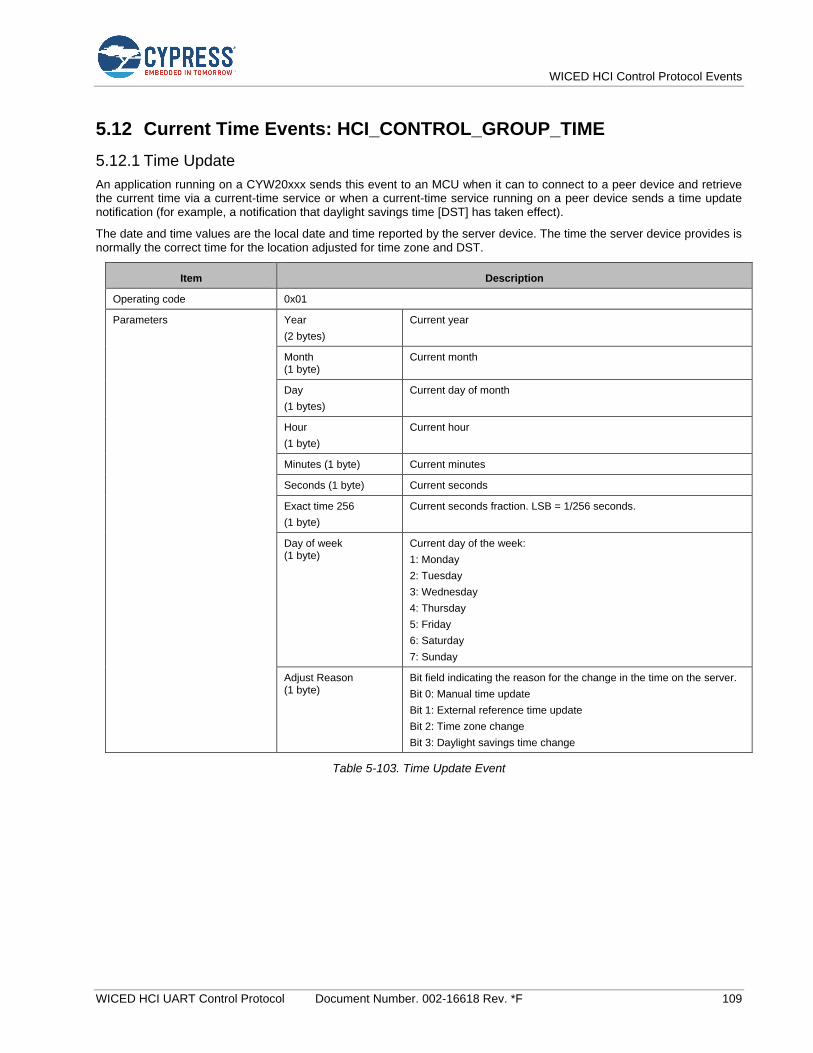
WICED HCI Control Protocol Events
WICED HCI UART Control Protocol Document Number. 002-16618 Rev. *F 109
5.12 Current Time Events: HCI_CONTROL_GROUP_TIME
5.12.1 Time Update
An application running on a CYW20xxx sends this event to an MCU when it can to connect to a peer device and retrieve the current time via a current-time service or when a current-time service running on a peer device sends a time update notification (for example, a notification that daylight savings time [DST] has taken effect).
The date and time values are the local date and time reported by the server device. The time the server device provides is normally the correct time for the location adjusted for time zone and DST.
Item Description
Operating code 0x01
Parameters Year
(2 bytes)
Current year
Month (1 byte)
Current month
Day
(1 bytes)
Current day of month
Hour
(1 byte)
Current hour
Minutes (1 byte) Current minutes
Seconds (1 byte) Current seconds
Exact time 256
(1 byte)
Current seconds fraction. LSB = 1/256 seconds.
Day of week (1 byte)
Current day of the week:
1: Monday
2: Tuesday
3: Wednesday
4: Thursday
5: Friday
6: Saturday
7: Sunday
Adjust Reason (1 byte)
Bit field indicating the reason for the change in the time on the server.
Bit 0: Manual time update
Bit 1: External reference time update
Bit 2: Time zone change
Bit 3: Daylight savings time change
Table 5-103. Time Update Event

WICED HCI Control Protocol Events
WICED HCI UART Control Protocol Document Number. 002-16618 Rev. *F 110
5.13 Test Events: HCI_CONTROL_GROUP_TEST
The Test events pertain to the Test command functionality to allow the host to execute various tests on the CYW20xxx.
5.13.1 Encapsulated HCI Event
While in the Test Mode, the application encapsulates all the HCI Events received from the controller in the Encapsulated HCI Events and sends them to the MCU.
Item Description
Operating code 0x10
Parameters HCI Event (variable bytes) Fully formatted HCI Event
Table 5-104. Encapsulated HCI Event
5.14 ANCS Events: HCI_CONTROL_GROUP_ANCS
The Apple Notification Control Service (ANCS) events pertain to the ANCS commands that let an MCU perform various ANCS-related procedures using the CYW20xxx. Refer to the Apple ANCS Specification [3] for more information.
5.14.1 ANCS Notification
An application running on a CYW20xxx sends this event to an MCU when it receives a notification from a connected iOS device.
Item Description
Operating code 0x01
Parameters Notification UID (4 bytes)
Notification Unique Identifier
Event ID (1 byte)
0: Notification added
1: Notification modified
2: Notification removed
Category (1 bytes)
0: Other
1: Incoming call
2: Missed call
3: Voicemail
4: Social
5: Schedule
6: Email
7: News
8: Health and fitness
9: Business and finance
10: Location
11: Entertainment
Flags (1 byte)
Bit mask of event flags Bit 0: Silent
Bit 2: Important
Bit 3: Preexisting
Bit 4: Positive action possible
Bit 5: Negative action possible
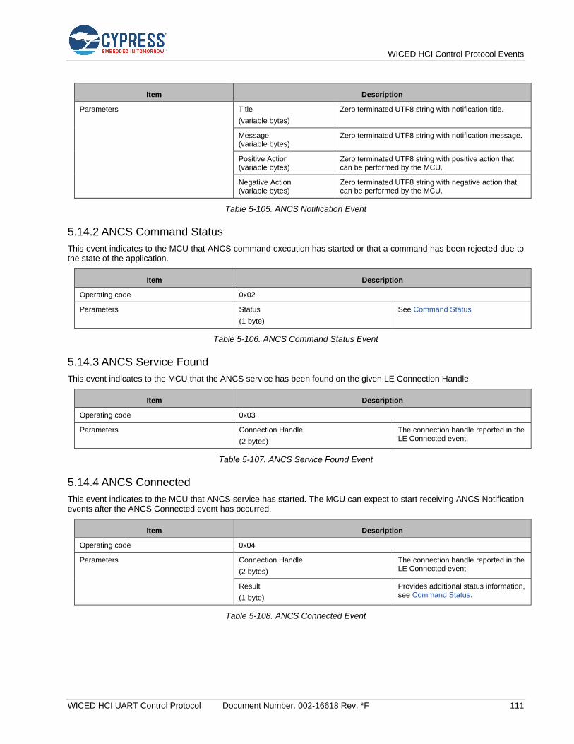
WICED HCI Control Protocol Events
WICED HCI UART Control Protocol Document Number. 002-16618 Rev. *F 111
Item Description
Parameters Title
(variable bytes)
Zero terminated UTF8 string with notification title.
Message (variable bytes)
Zero terminated UTF8 string with notification message.
Positive Action (variable bytes)
Zero terminated UTF8 string with positive action that can be performed by the MCU.
Negative Action (variable bytes)
Zero terminated UTF8 string with negative action that can be performed by the MCU.
Table 5-105. ANCS Notification Event
5.14.2 ANCS Command Status
This event indicates to the MCU that ANCS command execution has started or that a command has been rejected due to the state of the application.
Item Description
Operating code 0x02
Parameters Status
(1 byte)
See Command Status
Table 5-106. ANCS Command Status Event
5.14.3 ANCS Service Found
This event indicates to the MCU that the ANCS service has been found on the given LE Connection Handle.
Item Description
Operating code 0x03
Parameters Connection Handle
(2 bytes)
The connection handle reported in the LE Connected event.
Table 5-107. ANCS Service Found Event
5.14.4 ANCS Connected
This event indicates to the MCU that ANCS service has started. The MCU can expect to start receiving ANCS Notification events after the ANCS Connected event has occurred.
Item Description
Operating code 0x04
Parameters Connection Handle
(2 bytes)
The connection handle reported in the LE Connected event.
Result
(1 byte)
Provides additional status information, see Command Status.
Table 5-108. ANCS Connected Event

WICED HCI Control Protocol Events
WICED HCI UART Control Protocol Document Number. 002-16618 Rev. *F 112
5.14.5 ANCS Disconnected
This event indicates to the MCU that ANCS service has stopped or has been unsubscribed to. ANCS Notification events shall not occur after the ANCS service has been disconnected.
Item Description
Operating code 0x05
Parameters Connection Handle
(2 bytes)
The connection handle reported in the LE Connected event.
Result
(1 byte)
Provides additional status information, see Command Status
Table 5-109. ANCS Disconnected Event
5.15 AMS Events: HCI_CONTROL_GROUP_AMS
The Apple Media Service (AMS) events pertain to the AMS commands that let an MCU perform various AMS-related procedures using the CYW20xxx. Refer to the Apple developer AMS Specification [4] for more information:
5.15.1 AMS Command Status
This event indicates to the MCU that AMS command execution has started or that a command has been rejected due to the state of the application.
Item Description
Operating code 0x01
Parameters Status
(1 byte)
See Command Status
Table 5-110. AMS Command Status Event
5.15.2 AMS Service Found
This event indicates to the MCU that the AMS service has been found on the given LE Connection Handle.
Item Description
Operating code 0x02
Parameters Connection Handle
(2 bytes)
The connection handle reported in the LE Connected event.
Table 5-111. AMS Service Found Event
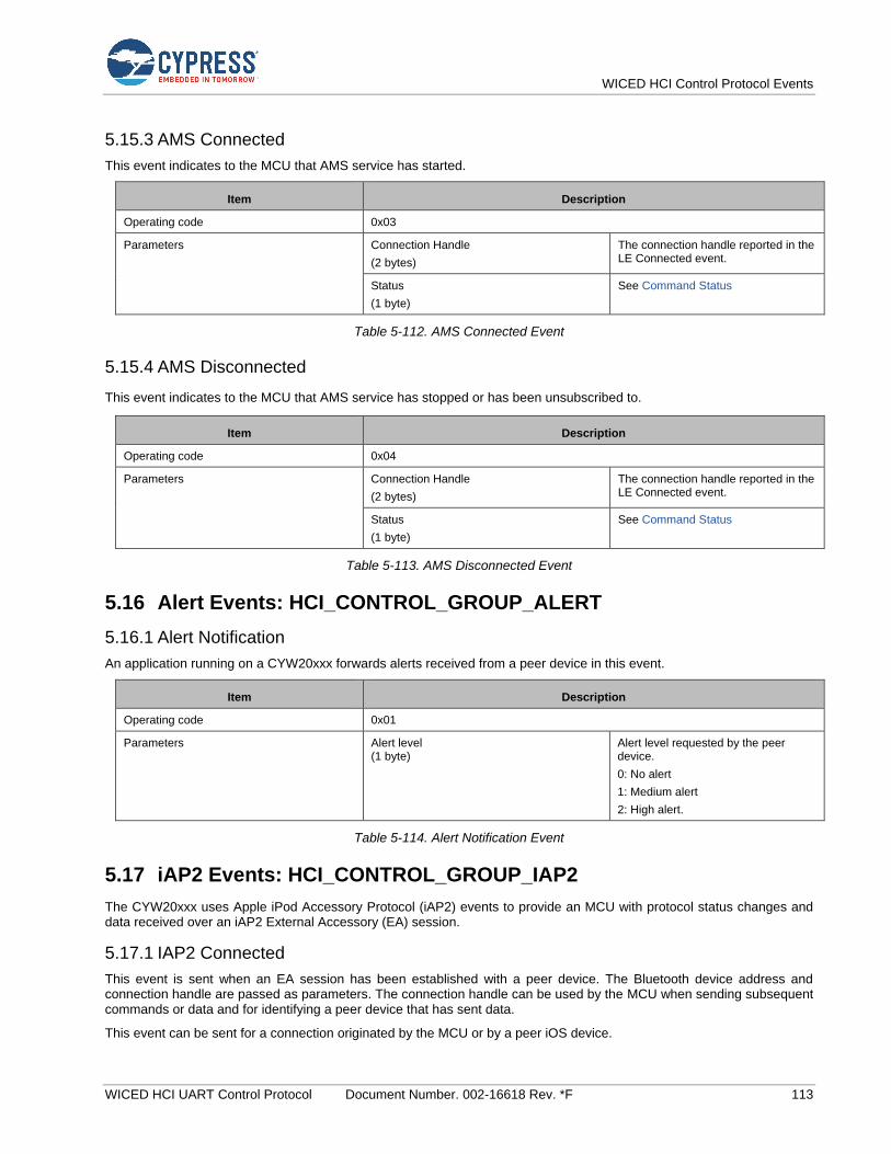
WICED HCI Control Protocol Events
WICED HCI UART Control Protocol Document Number. 002-16618 Rev. *F 113
5.15.3 AMS Connected
This event indicates to the MCU that AMS service has started.
Item Description
Operating code 0x03
Parameters Connection Handle
(2 bytes)
The connection handle reported in the LE Connected event.
Status
(1 byte)
See Command Status
Table 5-112. AMS Connected Event
5.15.4 AMS Disconnected
This event indicates to the MCU that AMS service has stopped or has been unsubscribed to.
Item Description
Operating code 0x04
Parameters Connection Handle
(2 bytes)
The connection handle reported in the LE Connected event.
Status
(1 byte)
See Command Status
Table 5-113. AMS Disconnected Event
5.16 Alert Events: HCI_CONTROL_GROUP_ALERT
5.16.1 Alert Notification
An application running on a CYW20xxx forwards alerts received from a peer device in this event.
Item Description
Operating code 0x01
Parameters Alert level (1 byte)
Alert level requested by the peer device.
0: No alert
1: Medium alert
2: High alert.
Table 5-114. Alert Notification Event
5.17 iAP2 Events: HCI_CONTROL_GROUP_IAP2
The CYW20xxx uses Apple iPod Accessory Protocol (iAP2) events to provide an MCU with protocol status changes and data received over an iAP2 External Accessory (EA) session.
5.17.1 IAP2 Connected
This event is sent when an EA session has been established with a peer device. The Bluetooth device address and connection handle are passed as parameters. The connection handle can be used by the MCU when sending subsequent commands or data and for identifying a peer device that has sent data.
This event can be sent for a connection originated by the MCU or by a peer iOS device.
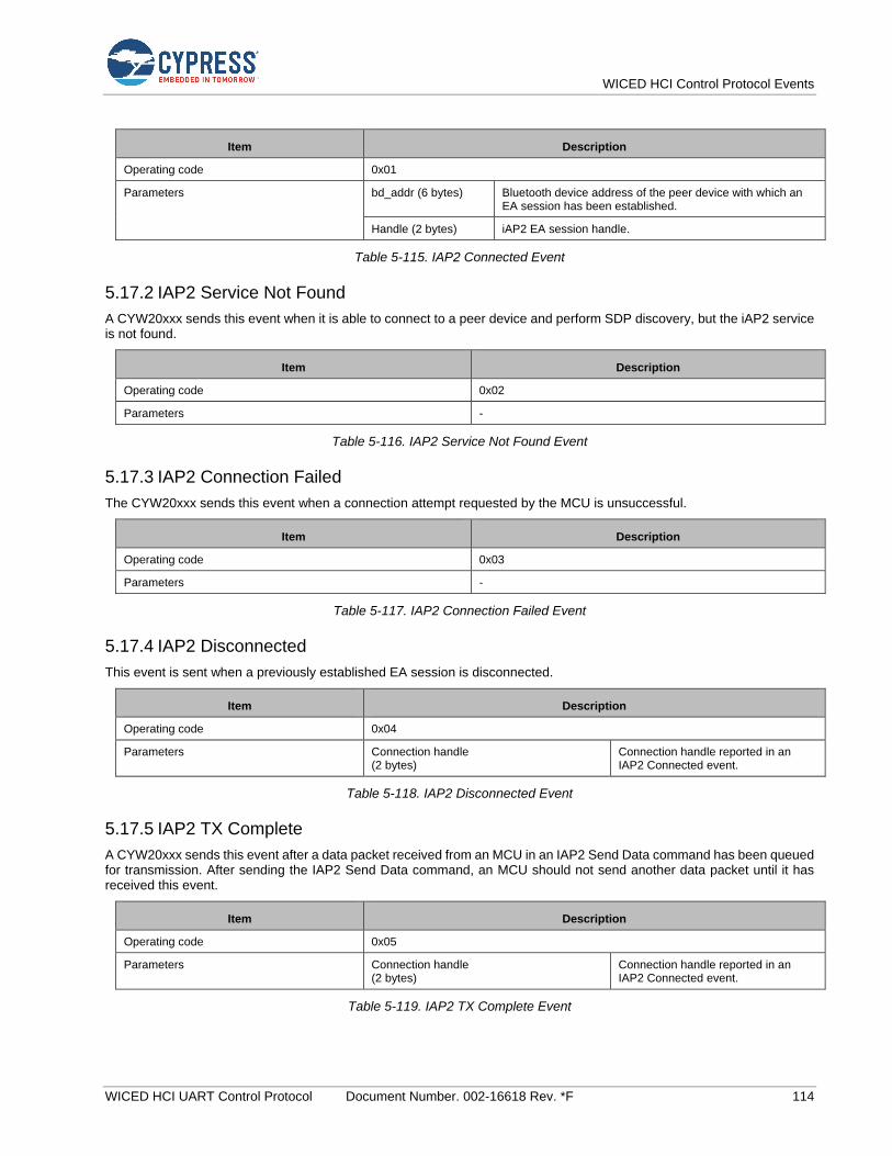
WICED HCI Control Protocol Events
WICED HCI UART Control Protocol Document Number. 002-16618 Rev. *F 114
Item Description
Operating code 0x01
Parameters bd_addr (6 bytes) Bluetooth device address of the peer device with which an EA session has been established.
Handle (2 bytes) iAP2 EA session handle.
Table 5-115. IAP2 Connected Event
5.17.2 IAP2 Service Not Found
A CYW20xxx sends this event when it is able to connect to a peer device and perform SDP discovery, but the iAP2 service is not found.
Item Description
Operating code 0x02
Parameters -
Table 5-116. IAP2 Service Not Found Event
5.17.3 IAP2 Connection Failed
The CYW20xxx sends this event when a connection attempt requested by the MCU is unsuccessful.
Item Description
Operating code 0x03
Parameters -
Table 5-117. IAP2 Connection Failed Event
5.17.4 IAP2 Disconnected
This event is sent when a previously established EA session is disconnected.
Item Description
Operating code 0x04
Parameters Connection handle (2 bytes)
Connection handle reported in an IAP2 Connected event.
Table 5-118. IAP2 Disconnected Event
5.17.5 IAP2 TX Complete
A CYW20xxx sends this event after a data packet received from an MCU in an IAP2 Send Data command has been queued for transmission. After sending the IAP2 Send Data command, an MCU should not send another data packet until it has received this event.
Item Description
Operating code 0x05
Parameters Connection handle (2 bytes)
Connection handle reported in an IAP2 Connected event.
Table 5-119. IAP2 TX Complete Event
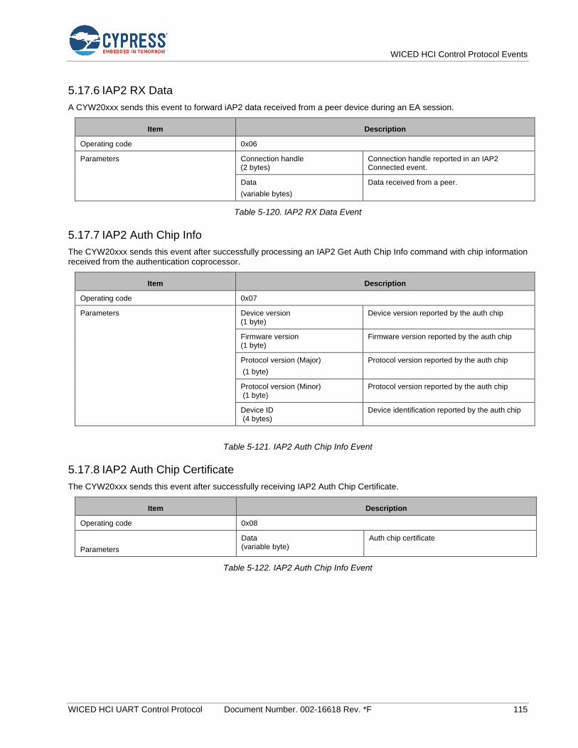
WICED HCI Control Protocol Events
WICED HCI UART Control Protocol Document Number. 002-16618 Rev. *F 115
5.17.6 IAP2 RX Data
A CYW20xxx sends this event to forward iAP2 data received from a peer device during an EA session.
Item Description
Operating code 0x06
Parameters Connection handle (2 bytes)
Connection handle reported in an IAP2 Connected event.
Data
(variable bytes)
Data received from a peer.
Table 5-120. IAP2 RX Data Event
5.17.7 IAP2 Auth Chip Info
The CYW20xxx sends this event after successfully processing an IAP2 Get Auth Chip Info command with chip information received from the authentication coprocessor.
Item Description
Operating code 0x07
Parameters Device version (1 byte)
Device version reported by the auth chip
Firmware version (1 byte)
Firmware version reported by the auth chip
Protocol version (Major)
(1 byte)
Protocol version reported by the auth chip
Protocol version (Minor) (1 byte)
Protocol version reported by the auth chip
Device ID (4 bytes)
Device identification reported by the auth chip
Table 5-121. IAP2 Auth Chip Info Event
5.17.8 IAP2 Auth Chip Certificate
The CYW20xxx sends this event after successfully receiving IAP2 Auth Chip Certificate.
Item Description
Operating code 0x08
Parameters
Data (variable byte)
Auth chip certificate
Table 5-122. IAP2 Auth Chip Info Event
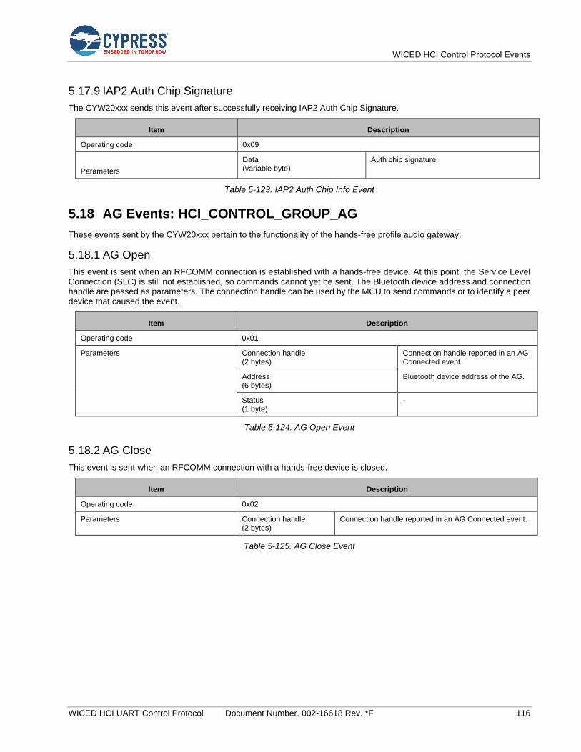
WICED HCI Control Protocol Events
WICED HCI UART Control Protocol Document Number. 002-16618 Rev. *F 116
5.17.9 IAP2 Auth Chip Signature
The CYW20xxx sends this event after successfully receiving IAP2 Auth Chip Signature.
Item Description
Operating code 0x09
Parameters
Data (variable byte)
Auth chip signature
Table 5-123. IAP2 Auth Chip Info Event
5.18 AG Events: HCI_CONTROL_GROUP_AG
These events sent by the CYW20xxx pertain to the functionality of the hands-free profile audio gateway.
5.18.1 AG Open
This event is sent when an RFCOMM connection is established with a hands-free device. At this point, the Service Level Connection (SLC) is still not established, so commands cannot yet be sent. The Bluetooth device address and connection handle are passed as parameters. The connection handle can be used by the MCU to send commands or to identify a peer device that caused the event.
Item Description
Operating code 0x01
Parameters Connection handle (2 bytes)
Connection handle reported in an AG Connected event.
Address (6 bytes)
Bluetooth device address of the AG.
Status (1 byte)
-
Table 5-124. AG Open Event
5.18.2 AG Close
This event is sent when an RFCOMM connection with a hands-free device is closed.
Item Description
Operating code 0x02
Parameters Connection handle (2 bytes)
Connection handle reported in an AG Connected event.
Table 5-125. AG Close Event
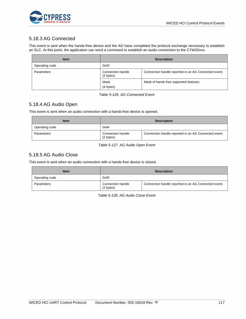
WICED HCI Control Protocol Events
WICED HCI UART Control Protocol Document Number. 002-16618 Rev. *F 117
5.18.3 AG Connected
This event is sent when the hands-free device and the AG have completed the protocol exchange necessary to establish an SLC. At this point, the application can send a command to establish an audio connection to the CYW20xxx.
Item Description
Operating code 0x03
Parameters Connection handle (2 bytes)
Connection handle reported in an AG Connected event.
Mask
(4 bytes)
Mask of hands-free supported features.
Table 5-126. AG Connected Event
5.18.4 AG Audio Open
This event is sent when an audio connection with a hands-free device is opened.
Item Description
Operating code 0x04
Parameters Connection handle (2 bytes)
Connection handle reported in an AG Connected event.
Table 5-127. AG Audio Open Event
5.18.5 AG Audio Close
This event is sent when an audio connection with a hands-free device is closed.
Item Description
Operating code 0x05
Parameters Connection handle (2 bytes)
Connection handle reported in an AG Connected event.
Table 5-128. AG Audio Close Event
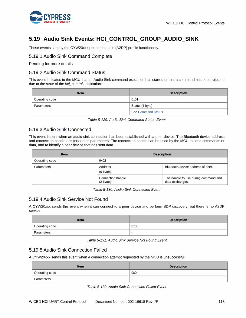
WICED HCI Control Protocol Events
WICED HCI UART Control Protocol Document Number. 002-16618 Rev. *F 118
5.19 Audio Sink Events: HCI_CONTROL_GROUP_AUDIO_SINK
These events sent by the CYW20xxx pertain to audio (A2DP) profile functionality.
5.19.1 Audio Sink Command Complete
Pending for more details.
5.19.2 Audio Sink Command Status
This event indicates to the MCU that an Audio Sink command execution has started or that a command has been rejected due to the state of the hci_control application.
Item Description
Operating code 0x01
Parameters Status (1 byte)
See Command Status
Table 5-129. Audio Sink Command Status Event
5.19.3 Audio Sink Connected
This event is sent when an audio sink connection has been established with a peer device. The Bluetooth device address and connection handle are passed as parameters. The connection handle can be used by the MCU to send commands or data, and to identify a peer device that has sent data.
Item Description
Operating code 0x02
Parameters Address
(6 bytes)
Bluetooth device address of peer.
Connection handle (2 bytes)
The handle to use during command and data exchanges.
Table 5-130. Audio Sink Connected Event
5.19.4 Audio Sink Service Not Found
A CYW20xxx sends this event when it can connect to a peer device and perform SDP discovery, but there is no A2DP service.
Item Description
Operating code 0x03
Parameters -
Table 5-131. Audio Sink Service Not Found Event
5.19.5 Audio Sink Connection Failed
A CYW20xxx sends this event when a connection attempt requested by the MCU is unsuccessful.
Item Description
Operating code 0x04
Parameters -
Table 5-132. Audio Sink Connection Failed Event
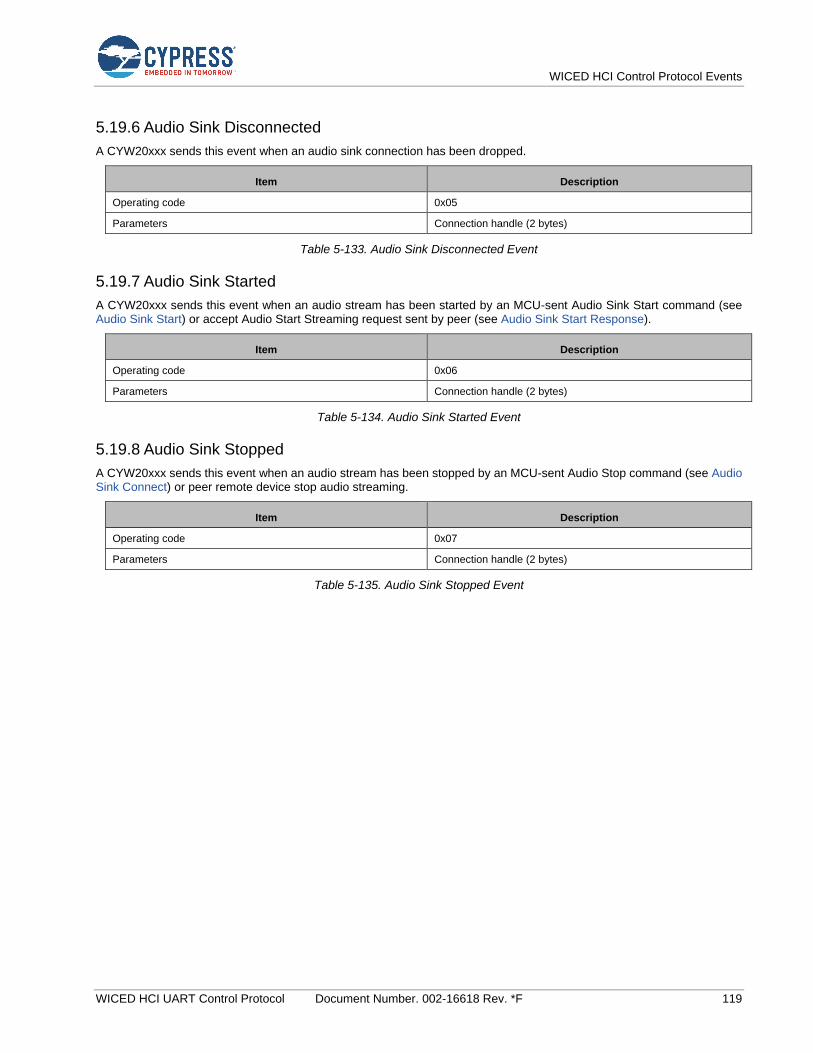
WICED HCI Control Protocol Events
WICED HCI UART Control Protocol Document Number. 002-16618 Rev. *F 119
5.19.6 Audio Sink Disconnected
A CYW20xxx sends this event when an audio sink connection has been dropped.
Item Description
Operating code 0x05
Parameters Connection handle (2 bytes)
Table 5-133. Audio Sink Disconnected Event
5.19.7 Audio Sink Started
A CYW20xxx sends this event when an audio stream has been started by an MCU-sent Audio Sink Start command (see Audio Sink Start) or accept Audio Start Streaming request sent by peer (see Audio Sink Start Response).
Item Description
Operating code 0x06
Parameters Connection handle (2 bytes)
Table 5-134. Audio Sink Started Event
5.19.8 Audio Sink Stopped
A CYW20xxx sends this event when an audio stream has been stopped by an MCU-sent Audio Stop command (see Audio Sink Connect) or peer remote device stop audio streaming.
Item Description
Operating code 0x07
Parameters Connection handle (2 bytes)
Table 5-135. Audio Sink Stopped Event
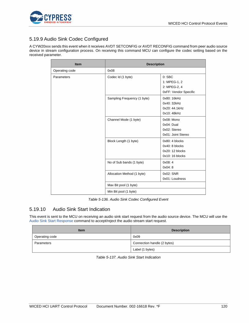
WICED HCI Control Protocol Events
WICED HCI UART Control Protocol Document Number. 002-16618 Rev. *F 120
5.19.9 Audio Sink Codec Configured
A CYW20xxx sends this event when it receives AVDT SETCONFIG or AVDT RECONFIG command from peer audio source device in stream configuration process. On receiving this command MCU can configure the codec setting based on the received parameter.
Item Description
Operating code 0x08
Parameters Codec Id (1 byte) 0: SBC
1: MPEG-1, 2
2: MPEG-2, 4
0xFF: Vendor Specific
Sampling Frequency (1 byte) 0x80: 16kHz
0x40: 32kHz
0x20: 44.1kHz
0x10: 48kHz
Channel Mode (1 byte) 0x08: Mono
0x04: Dual
0x02: Stereo
0x01: Joint Stereo
Block Length (1 byte) 0x80: 4 blocks
0x40: 8 blocks
0x20: 12 blocks
0x10: 16 blocks
No of Sub bands (1 byte) 0x08: 4
0x04: 8
Allocation Method (1 byte) 0x02: SNR
0x01: Loudness
Max Bit pool (1 byte)
Min Bit pool (1 byte)
Table 5-136. Audio Sink Codec Configured Event
5.19.10 Audio Sink Start Indication
This event is sent to the MCU on receiving an audio sink start request from the audio source device. The MCU will use the Audio Sink Start Response command to accept/reject the audio stream start request.
Item Description
Operating code 0x09
Parameters Connection handle (2 bytes)
Label (1 bytes)
Table 5-137. Audio Sink Start Indication
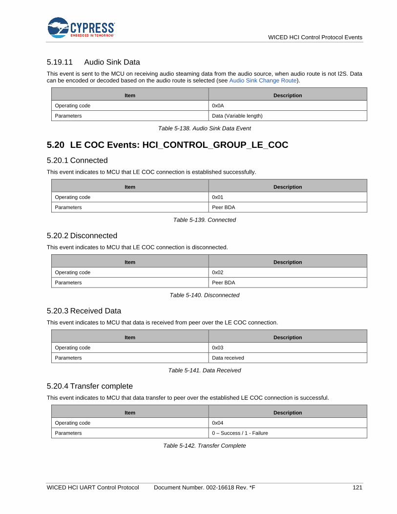
WICED HCI Control Protocol Events
WICED HCI UART Control Protocol Document Number. 002-16618 Rev. *F 121
5.19.11 Audio Sink Data
This event is sent to the MCU on receiving audio steaming data from the audio source, when audio route is not I2S. Data can be encoded or decoded based on the audio route is selected (see Audio Sink Change Route).
Item Description
Operating code 0x0A
Parameters Data (Variable length)
Table 5-138. Audio Sink Data Event
5.20 LE COC Events: HCI_CONTROL_GROUP_LE_COC
5.20.1 Connected
This event indicates to MCU that LE COC connection is established successfully.
Item Description
Operating code 0x01
Parameters Peer BDA
Table 5-139. Connected
5.20.2 Disconnected
This event indicates to MCU that LE COC connection is disconnected.
Item Description
Operating code 0x02
Parameters Peer BDA
Table 5-140. Disconnected
5.20.3 Received Data
This event indicates to MCU that data is received from peer over the LE COC connection.
Item Description
Operating code 0x03
Parameters Data received
Table 5-141. Data Received
5.20.4 Transfer complete
This event indicates to MCU that data transfer to peer over the established LE COC connection is successful.
Item Description
Operating code 0x04
Parameters 0 – Success / 1 - Failure
Table 5-142. Transfer Complete
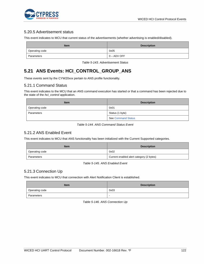
WICED HCI Control Protocol Events
WICED HCI UART Control Protocol Document Number. 002-16618 Rev. *F 122
5.20.5 Advertisement status
This event indicates to MCU that current status of the advertisements (whether advertising is enabled/disabled).
Item Description
Operating code 0x05
Parameters 0 – ADV OFF
Table 5-143. Advertisement Status
5.21 ANS Events: HCI_CONTROL_GROUP_ANS
These events sent by the CYW20xxx pertain to ANS profile functionality.
5.21.1 Command Status
This event indicates to the MCU that an ANS command execution has started or that a command has been rejected due to the state of the hci_control application.
Item Description
Operating code 0x01
Parameters Status (1 byte)
See Command Status
Table 5-144. ANS Command Status Event
5.21.2 ANS Enabled Event
This event indicates to MCU that ANS functionality has been initialized with the Current Supported categories.
Item Description
Operating code 0x02
Parameters Current enabled alert category (2 bytes)
Table 5-145. ANS Enabled Event
5.21.3 Connection Up
This event indicates to MCU that connection with Alert Notification Client is established.
Item Description
Operating code 0x03
Parameters -
Table 5-146. ANS Connection Up
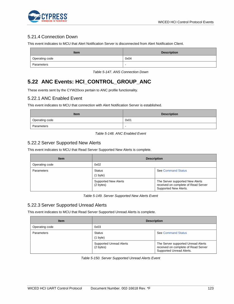
WICED HCI Control Protocol Events
WICED HCI UART Control Protocol Document Number. 002-16618 Rev. *F 123
5.21.4 Connection Down
This event indicates to MCU that Alert Notification Server is disconnected from Alert Notification Client.
Item Description
Operating code 0x04
Parameters -
Table 5-147. ANS Connection Down
5.22 ANC Events: HCI_CONTROL_GROUP_ANC
These events sent by the CYW20xxx pertain to ANC profile functionality.
5.22.1 ANC Enabled Event
This event indicates to MCU that connection with Alert Notification Server is established.
Item Description
Operating code 0x01
Parameters -
Table 5-148. ANC Enabled Event
5.22.2 Server Supported New Alerts
This event indicates to MCU that Read Server Supported New Alerts is complete.
Item Description
Operating code 0x02
Parameters Status
(1 byte)
See Command Status
Supported New Alerts (2 bytes)
The Server supported New Alerts received on complete of Read Server Supported New Alerts.
Table 5-149. Server Supported New Alerts Event
5.22.3 Server Supported Unread Alerts
This event indicates to MCU that Read Server Supported Unread Alerts is complete.
Item Description
Operating code 0x03
Parameters Status
(1 byte)
See Command Status
Supported Unread Alerts (2 bytes)
The Server supported Unread Alerts received on complete of Read Server Supported Unread Alerts.
Table 5-150. Server Supported Unread Alerts Event
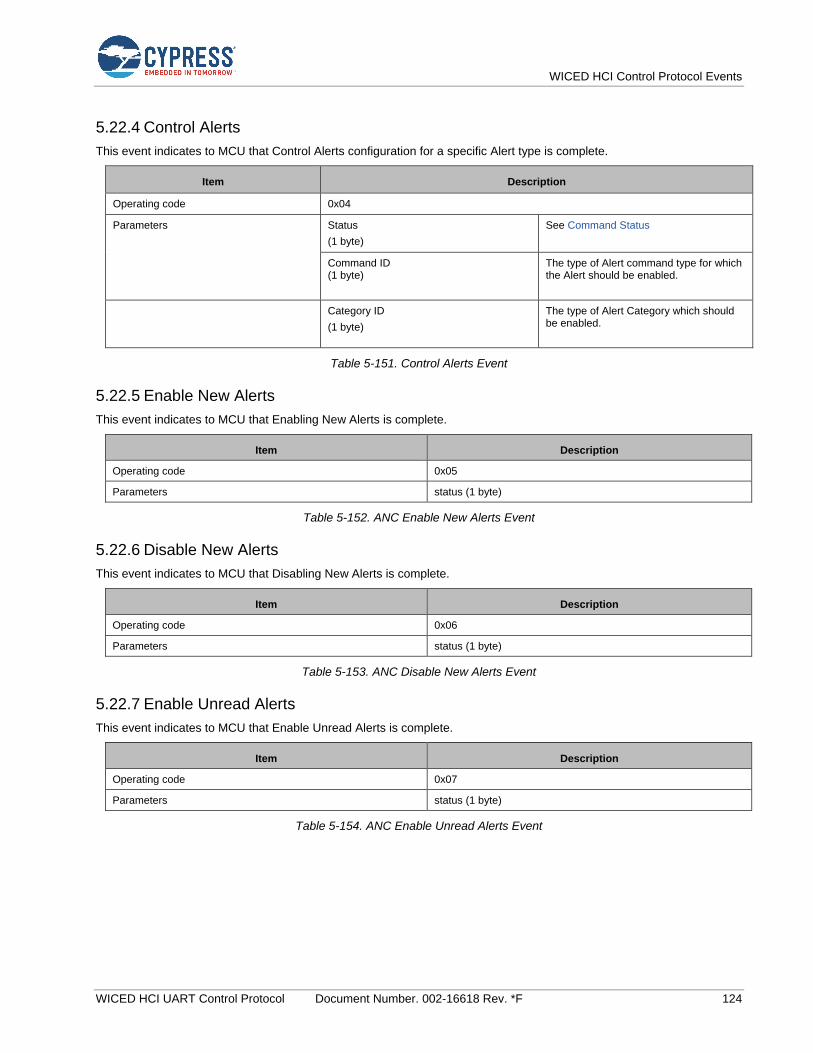
WICED HCI Control Protocol Events
WICED HCI UART Control Protocol Document Number. 002-16618 Rev. *F 124
5.22.4 Control Alerts
This event indicates to MCU that Control Alerts configuration for a specific Alert type is complete.
Item Description
Operating code 0x04
Parameters Status
(1 byte)
See Command Status
Command ID (1 byte)
The type of Alert command type for which the Alert should be enabled.
Category ID
(1 byte)
The type of Alert Category which should be enabled.
Table 5-151. Control Alerts Event
5.22.5 Enable New Alerts
This event indicates to MCU that Enabling New Alerts is complete.
Item Description
Operating code 0x05
Parameters status (1 byte)
Table 5-152. ANC Enable New Alerts Event
5.22.6 Disable New Alerts
This event indicates to MCU that Disabling New Alerts is complete.
Item Description
Operating code 0x06
Parameters status (1 byte)
Table 5-153. ANC Disable New Alerts Event
5.22.7 Enable Unread Alerts
This event indicates to MCU that Enable Unread Alerts is complete.
Item Description
Operating code 0x07
Parameters status (1 byte)
Table 5-154. ANC Enable Unread Alerts Event

WICED HCI Control Protocol Events
WICED HCI UART Control Protocol Document Number. 002-16618 Rev. *F 125
5.22.8 Disable Unread Alerts
This event indicates to MCU that Disabling Unread Alerts is complete.
Item Description
Operating code 0x08
Parameters status (1 byte)
Table 5-155. ANC Disable Unread Alerts Event
5.22.9 ANC Disabled Event
This event indicates to MCU that there is a disconnection with Alert Notification Server.
Item Description
Operating code 0x09
Parameters -
Table 5-156. ANC Disabled Event
5.22.10 Command Status
This event indicates the command status for the requested operation to the MCU.
Item Description
Operating code 0x09
Parameters Status (1 byte)
Table 5-157. ANC Command Status Event
5.23 Miscellaneous Events: HCI_CONTROL_GROUP_MISC
These events sent by the CYW20xxx pertain to miscellaneous group of commands.
5.23.1 Ping Request Reply
This miscellaneous event is sent when the host sends a Ping Request (see Ping Request). The CYW20xxx device responds with the exact data received in the Ping Request.
Item Description
Operating code 0x01
Parameters Data (variable bytes)
Table 5-158. Ping Request Reply Event
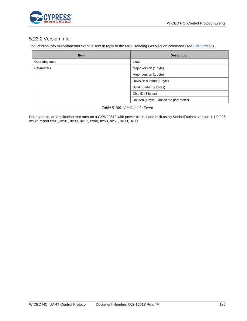
WICED HCI Control Protocol Events
WICED HCI UART Control Protocol Document Number. 002-16618 Rev. *F 126
5.23.2 Version Info
The Version Info miscellaneous event is sent in reply to the MCU sending Get Version command (see Get Version).
Item Description
Operating code 0x02
Parameters Major version (1 byte)
Minor version (1 byte)
Revision number (1 byte)
Build number (2 bytes)
Chip ID (3 bytes)
Unused (1 byte – obsoleted parameter)
Table 5-159. Version Info Event
For example, an application that runs on a CYW20819 with power class 1 and built using ModusToolbox version 1.1.0.225 would report 0x01, 0x01, 0x00, 0xE1, 0x00, 0x53, 0x51, 0x00, 0x00.
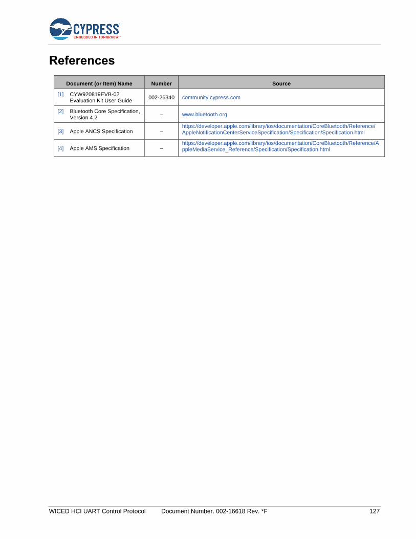
WICED HCI UART Control Protocol Document Number. 002-16618 Rev. *F 127
References
Document (or Item) Name Number Source
[1] CYW920819EVB-02 Evaluation Kit User Guide
002-26340 community.cypress.com
[2] Bluetooth Core Specification, Version 4.2
– www.bluetooth.org
[3] Apple ANCS Specification – https://developer.apple.com/library/ios/documentation/CoreBluetooth/Reference/ AppleNotificationCenterServiceSpecification/Specification/Specification.html
[4] Apple AMS Specification – https://developer.apple.com/library/ios/documentation/CoreBluetooth/Reference/AppleMediaService_Reference/Specification/Specification.html
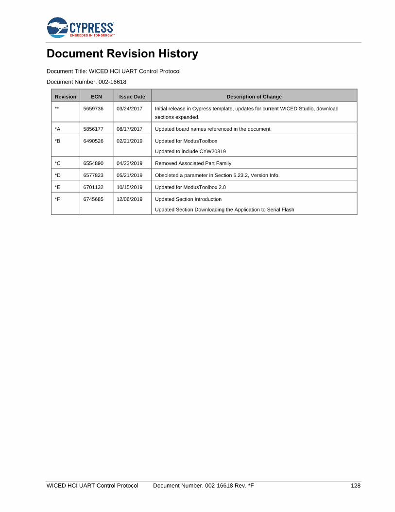
WICED HCI UART Control Protocol Document Number. 002-16618 Rev. *F 128
Document Revision History
Document Title: WICED HCI UART Control Protocol
Document Number: 002-16618
Revision ECN Issue Date Description of Change
** 5659736 03/24/2017 Initial release in Cypress template, updates for current WICED Studio, download
sections expanded.
*A 5856177 08/17/2017 Updated board names referenced in the document
*B 6490526 02/21/2019 Updated for ModusToolbox
Updated to include CYW20819
*C 6554890 04/23/2019 Removed Associated Part Family
*D 6577823 05/21/2019 Obsoleted a parameter in Section 5.23.2, Version Info.
*E 6701132 10/15/2019 Updated for ModusToolbox 2.0
*F 6745685 12/06/2019 Updated Section Introduction
Updated Section Downloading the Application to Serial Flash

WICED HCI UART Control Protocol Document Number. 002-16618 Rev. *F 129
Worldwide Sales and Design Support
Cypress maintains a worldwide network of offices, solution centers, manufacturer’s representatives, and distributors. To find the office closest to you, visit us at Cypress Locations.
Products
Arm® Cortex® Microcontrollers cypress.com/arm
Automotive cypress.com/automotive
Clocks & Buffers cypress.com/clocks
Interface cypress.com/interface
Internet of Things cypress.com/iot
Memory cypress.com/memory
Microcontrollers cypress.com/mcu
PSoC cypress.com/psoc
Power Management ICs cypress.com/pmic
Touch Sensing cypress.com/touch
USB Controllers cypress.com/usb
Wireless Connectivity cypress.com/wireless
PSoC® Solutions
PSoC 1 | PSoC 3 | PSoC 4 | PSoC 5LP | PSoC 6 MCU
Cypress Developer Community
Community | Projects | Videos | Blogs | Training | Components
Technical Support
cypress.com/support
Cypress Semiconductor 198 Champion Court San Jose, CA 95134-1709
© Cypress Semiconductor Corporation, 2017-2019. This document is the property of Cypress Semiconductor Corporation and its subsidiaries (“Cypress”). This document, including any software or firmware included or referenced in this document (“Software”), is owned by Cypress under the intellectual property laws and treaties of the United States and other countries worldwide. Cypress reserves all rights under such laws and treaties and does not, except as specifically stated in this paragraph, grant any license under its patents, copyrights, trademarks, or other intellectual property rights. If the Software is not accompanied by a license agreement and you do not otherwise have a written agreement with Cypress governing the use of the Software, then Cypress hereby grants you a personal, non-exclusive, nontransferable license (without the right to sublicense) (1) under its copyright rights in the Software (a) for Software provided in source code form, to modify and reproduce the Software solely for use with Cypress hardware products, only internally within your organization, and (b) to distribute the Software in binary code form externally to end users (either directly or indirectly through resellers and distributors), solely for use on Cypress hardware product units, and (2) under those claims of Cypress’s patents that are infringed by the Software (as provided by Cypress, unmodified) to make, use, distribute, and import the Software solely for use with Cypress hardware products. Any other use, reproduction, modification, translation, or compilation of the Software is prohibited.
TO THE EXTENT PERMITTED BY APPLICABLE LAW, CYPRESS MAKES NO WARRANTY OF ANY KIND, EXPRESS OR IMPLIED, WITH REGARD TO THIS DOCUMENT OR ANY SOFTWARE OR ACCOMPANYING HARDWARE, INCLUDING, BUT NOT LIMITED TO, THE IMPLIED WARRANTIES OF MERCHANTABILITY AND FITNESS FOR A PARTICULAR PURPOSE. No computing device can be absolutely secure. Therefore, despite security measures implemented in Cypress hardware or software products, Cypress shall have no liability arising out of any security breach, such as unauthorized access to or use of a Cypress product. CYPRESS DOES NOT REPRESENT, WARRANT, OR GUARANTEE THAT CYPRESS PRODUCTS, OR SYSTEMS CREATED USING CYPRESS PRODUCTS, WILL BE FREE FROM CORRUPTION, ATTACK, VIRUSES, INTERFERENCE, HACKING, DATA LOSS OR THEFT, OR OTHER SECURITY INTRUSION (collectively, “Security Breach”). Cypress disclaims any liability relating to any Security Breach, and you shall and hereby do release Cypress from any claim, damage, or other liability arising from any Security Breach. In addition, the products described in these materials may contain design defects or errors known as errata which may cause the product to deviate from published specifications. To the extent permitted by applicable law, Cypress reserves the right to make changes to this document without further notice. Cypress does not assume any liability arising out of the application or use of any product or circuit described in this document. Any information provided in this document, including any sample design information or programming code, is provided only for reference purposes. It is the responsibility of the user of this document to properly design, program, and test the functionality and safety of any application made of this information and any resulting product. “High-Risk Device” means any device or system whose failure could cause personal injury, death, or property damage. Examples of High-Risk Devices are weapons, nuclear installations, surgical implants, and other medical devices. “Critical Component” means any component of a High-Risk Device whose failure to perform can be reasonably expected to cause, directly or indirectly, the failure of the High-Risk Device, or to affect its safety or effectiveness. Cypress is not liable, in whole or in part, and you shall and hereby do release Cypress from any claim, damage, or other liability arising from any use of a Cypress product as a Critical Component in a High-Risk Device. You shall indemnify and hold Cypress, its directors, officers, employees, agents, affiliates, distributors, and assigns harmless from and against all claims, costs, damages, and expenses, arising out of any claim, including claims for product liability, personal injury or death, or property damage arising from any use of a Cypress product as a Critical Component in a High-Risk Device. Cypress products are not intended or authorized for use as a Critical Component in any High-Risk Device except to the limited extent that (i) Cypress’s published data sheet for the product explicitly states Cypress has qualified the product for use in a specific High-Risk Device, or (ii) Cypress has given you advance written authorization to use the product as a Critical Component in the specific High-Risk Device and you have signed a separate indemnification agreement.
Cypress, the Cypress logo, Spansion, the Spansion logo, and combinations thereof, WICED, PSoC, CapSense, EZ-USB, F-RAM, and Traveo are trademarks or registered trademarks of Cypress in the United States and other countries. For a more complete list of Cypress trademarks, visit cypress.com. Other names and brands may be claimed as property of their respective owners.


![[Codientu.org] Uart](https://img.dokumen.tips/doc/110x75/55cf9ad7550346d033a3a8db/codientuorg-uart.jpg)