Embed Size (px)
Citation preview
Wi-Fi 6
Deployment Guidelines & Scenarios
Source: WBA Next-Gen Work Group Author(s): Wi-Fi 6 Project TeamIssue date: July 2019Version: 1.0Document status: Final

Report Title: Wi-Fi 6 Deployment Guidelines & Scenarios Issue Date: July 2019 Version: 1.0
Wireless Broadband Alliance Confidential & Proprietary Copyright © 2019
ABOUT THE WIRELESS BROADBAND ALLIANCE Founded in 2003, the vision of the Wireless Broadband Alliance (WBA) is to drive seamless, interoperable service experiences via Wi-Fi within the global wireless ecosystem. WBA’s mission is to enable collaboration between service providers, technology companies and organizations to achieve that vision. WBA undertakes programs and activities to address business and technical issues, as well as opportunities, for member companies. WBA work areas include advocacy, industry guidelines, trials and certification. Its key programs include NextGen Wi-Fi, 5G, IoT, Testing & Interoperability and Roaming, with member-led Work Groups dedicated to resolving standards and technical issues to promote end-to-end services and accelerate business opportunities. WBA’s membership is comprised of major operators and leading technology companies, including Broadcom, BSNL, Deutsche Telekom AG, Facebook, Google, HPE Aruba, Huawei, Microsoft, Ruckus, Shaw, SK Telecom and T-Mobile US. The WBA Board includes AT&T, Boingo Wireless, BT, Cisco Systems, Comcast, Deutsche Telekom AG, GlobalReach Technology, Intel and KT Corporation. For a complete list of current WBA members, please click here.
Follow Wireless Broadband Alliance at:
www.twitter.com/wballiance
http://www.facebook.com/WirelessBroadbandAlliance
https://www.linkedin.com/groups/50482

Report Title: Wi-Fi 6 Deployment Guidelines & Scenarios Issue Date: July 2019 Version: 1.0
Wireless Broadband Alliance Confidential & Proprietary Copyright © 2019
UNDERTAKINGS AND LIMITATION OF LIABILITY
This Document and all the information contained in this Document is provided on an ‘as is’ basis without warranty of any kind, either expressed or implied, including, but not limited to, the implied warranties of merchantability, fitness for particular purpose, or non-infringement.
In addition, the WBA (and all other organisations who may have contributed to this document) makes no representations or warranties about the accuracy, completeness, or suitability for any purpose of the information. The information may contain technical inaccuracies or typographical errors. All liabilities of the WBA (and all other organisations who may have contributed to this document) howsoever arising for any such inaccuracies, errors, incompleteness, suitability, merchantability, fitness and non-infringement are expressly excluded to the fullest extent permitted by law. None of the contributors make any representation or offer to license any of their intellectual property rights to the other, or to any third party. Nothing in this information or communication shall be relied on by any recipient.
The WBA also disclaims any responsibility for identifying the existence of or for evaluating the applicability of any claimed copyrights, patents, patent applications, or other intellectual property rights, and will take no position on the validity or scope of any such rights. The WBA takes no position regarding the validity or scope of any intellectual property or other rights that might be claimed to pertain to the implementation or use of the technology described in this document or the extent to which any license under such rights might or might not be available; nor does it represent that it has made any effort to identify any such rights.
Neither the WBA nor any of the other organisations who may have contributed to this document will be liable for loss or damage arising out of or in connection with the use of this information. This is a comprehensive limitation of liability that applies to all damages of any kind, including (without limitation) compensatory, direct, indirect or consequential damages, loss of data, income or profit, loss of or damage to property and claims of third-parties.
Report Title: Wi-Fi 6 Deployment Guidelines & Scenarios Issue Date: July 2019 Version: 1.0
Wireless Broadband Alliance Confidential & Proprietary Copyright © 2019
CONTENTS
Table of Contents 1. Introduction ................................................................................................................................................... 1
1.1. Purpose .......................................................................................................................................... 1
1.2. Scope .............................................................................................................................................. 2
2. Guidelines ..................................................................................................................................................... 2
2.1. RF planning and design ................................................................................................................ 2 2.1.1. Wi-Fi 6 Channel planning and design ............................................................................................. 2 2.1.2. Increased capacity demands & designing for high density with Wi-Fi 6 ......................................... 3 2.1.3. Band steering .................................................................................................................................. 4 2.1.4. MU-MIMO ........................................................................................................................................ 5 2.1.5. Maintaining backward compatibility ................................................................................................. 6 2.1.6. Tools for RF design and planning ................................................................................................... 7 2.1.7. Post deployment survey to collect KPIs ........................................................................................ 10
2.2. Infrastructure SLAs ..................................................................................................................... 10 2.2.1. Bandwidth ...................................................................................................................................... 10 2.2.2. Throughput (peak speeds) ............................................................................................................ 11 2.2.3. Range/Coverage (OFDMA related SLA) ....................................................................................... 11 2.2.4. Packet Loss ................................................................................................................................... 11 2.2.5. End-to-end latency ........................................................................................................................ 12 2.2.6. Spectral Efficiency ......................................................................................................................... 12 2.2.7. Spatial Re-use/Color codes ........................................................................................................... 12 2.2.8. Spatial Diversity ............................................................................................................................. 13 2.2.9. Concurrent Users .......................................................................................................................... 13 2.2.10. Power Consumption Measurements ............................................................................................. 14 2.2.11. Traffic Prioritization ........................................................................................................................ 15 2.2.12. Outdoor Performance .................................................................................................................... 15
2.3. Seamless Mobility ....................................................................................................................... 16
2.4. Preparing for Co-existence ........................................................................................................ 16 2.4.1. Backward compatibility with previous Wi-Fi generations .............................................................. 17
2.4.1.1. Co-existence with Radar ....................................................................................................... 17 2.4.1.2. Co-existence Satellite ............................................................................................................ 18
3. Deployment Scenarios ............................................................................................................................... 18
3.1. Public Venues .............................................................................................................................. 18
3.2. Entertainment/Stadiums ............................................................................................................. 18
3.3. Residential/MDU .......................................................................................................................... 19
3.4. Smart Cities/IoT ........................................................................................................................... 21 3.4.1. Site planning .................................................................................................................................. 22 3.4.2. Backhaul ........................................................................................................................................ 22
Report Title: Wi-Fi 6 Deployment Guidelines & Scenarios Issue Date: July 2019 Version: 1.0
Wireless Broadband Alliance Confidential & Proprietary Copyright © 2019
3.4.3. Community IoT .............................................................................................................................. 23 3.4.4. IoT deployment benefits ................................................................................................................ 23
3.5. Enterprise WLANs ....................................................................................................................... 24 3.5.1. Requirements and capabilities - Identifying important Wi-Fi 6 features for enterprise deployments ................................................................................................................................................. 24 3.5.2. Planning access point placement and upgrade sequencing for Wi-Fi 6 ....................................... 25 3.5.3. Associated infrastructure upgrades ............................................................................................... 26
4. Business Advantages & Case Studies ..................................................................................................... 26
4.1. Ecosystem.................................................................................................................................... 26
4.2. Case Study (Mettis Aerospace) ................................................................................................. 27
4.3. Case Study (Boingo Wireless) ................................................................................................... 28
5. Guidelines Maintenance Process ............................................................................................................. 29
Appendix A – Mapping PHY Features ............................................................................................................... 30
Appendix B – Mapping MAC Features .............................................................................................................. 31
FIGURES Figure 1: Wi-Fi 6 MU-MIMO enables spectrum to be used more efficiently (source Cisco) .......................... 5 Figure 2: Examples of incorrect AP placement (courtesy of 7signals) ........................................................... 8 Figure 3: Example of Stadium directional antennas ......................................................................................... 8 Figure 4: Omni-directional (Ch 6, 11) and directional (Ch 1) antennas ........................................................... 9
Report Title: Wi-Fi 6 Deployment Guidelines & Scenarios Issue Date: July 2019 Version: 1.0
1 Wireless Broadband Alliance Confidential & Proprietary Copyright © 2019
1. Introduction
What is driving Next Generation Wireless Services?
Increased Demand for Connectivity - There are now about 3.7 mobile devices deployed per capita. This is driving rapid growth in mobile data traffic requirements, which are projected to grow at 47% CAGR from 2018-2023. This growth is coming from multiple different product categories with different key requirements ranging from certain IoT use cases that require low data rates and low power consumption supported using small battery powered devices, through to augmented reality/virtual reality use cases that require extreme throughput and low latency, and autonomous vehicles require reliable communications and cloud access.
Moreover, the extended range of IoT verticals currently being discussed by the industry raises several issues that challenge the status quo of access infrastructure, opening doors for new technologies to operate using the unlicensed spectrum.
Use of License-exempt Spectrum – With nearly 70% of smartphone data being carried over Wi-Fi networks, it is clear that cellular deployments in licensed spectrum have not been able to keep pace with consumer demands for wireless data. As a result, there is heavy investment in 5G cellular to improve its competitiveness with Wi-Fi. While this investment may pay dividends in five (or more) years, with the launch of Wi-Fi 6 in 2019, Wi-Fi is already evolving to meet the growing demand for wireless data.
1.1. Purpose
Supporting the Wi-Fi industry with more consistent deployment methods that result in meeting end-user expectations, through achieving an industry-wide set of deployment guidelines that ensure a more standardized approach in effectively deploying breakthrough Wi-Fi 6 networks. The purpose of the document is therefore to identify and create the guidelines when deploying Wi-Fi 6, covering:
• Features of Wi-Fi 6 / IEEE 802.11ax standard as a foundation
• Provide description on the various aspects of deployment
• Cover the detail of different deployment scenarios
• Recommend any appropriate service-level agreements (SLAs) and possible thresholds for deployment
• Expose industry case studies covering different types of deployments
Report Title: Wi-Fi 6 Deployment Guidelines & Scenarios Issue Date: July 2019 Version: 1.0
2 Wireless Broadband Alliance Confidential & Proprietary Copyright © 2019
1.2. Scope
The scope of the document is to provide guidelines on all the various deployment factors. In general, it shall not enforce any thresholds on a deployment, but rather provide guidelines on what a recommended threshold might be and it is always up to the service provider to tune and choose a threshold depending on the business case and deployment scenario.
Also, it must be noted that the scope of the document is not limited to features of Wi-Fi 6; rather, it takes those features and identifies deployment guidelines for designing and deploying a Wi-Fi network in general.
For further consultation, there is also a Wi-Fi Deployment Guidelines document (https://www.wballiance.com/wi-fi-deployment-guidelines/) released by the WBA in 2018 that is focused on baseline network deployment.
2. Guidelines
This chapter outlines and describes few key deployment items that shall enable a Service Provider, Operator, Enterprise or Venue owner to gain insights when deploying a Wi-Fi network. The subsections in the chapter focuses on RF Channel planning and design including band steering, MU-MIMO, backward compatibility with any existing previous generation Wi-Fi and tools. A robust set of SLAs have been provided that can be used to measure the deployment and set any thresholds for different types of deployments and scenarios. Lastly there are subsections describing what can be done to achieve a seamless mobility and making sure the deployment co-exists with any other Wireless technology, should there be one deployed in that area or venue.
2.1. RF planning and design
2.1.1. Wi-Fi 6 Channel planning and design
The use of 80 and 160 MHz channels has long been available for use within 802.11ac (Wi-Fi 5), although difficult to employ within environments requiring multiple overlapping cells and/or contentious environments. Similar to Wi-Fi 5, Wi-Fi 6 also face challenges with the ability to cleanly use these larger channels, due to the limited channel reuse within the 5GHz spectrum.
While it is fully possible to utilize dynamic bandwidth operation within Wi-Fi 5, it has not always been widely implemented. In cases where it has been deployed, the behavior of an AP when interference is detected at a defined threshold within a secondary channel will result in the reduction of the channel to a smaller bandwidth (i.e. 20 or 40 MHzMHz) to avoid

Report Title: Wi-Fi 6 Deployment Guidelines & Scenarios Issue Date: July 2019 Version: 1.0
3 Wireless Broadband Alliance Confidential & Proprietary Copyright © 2019
the interference. Depending on the environment, one may rarely see 80 or 160MHz being used.
There are two potential features to the Wi-Fi 6 standard that may assist with the dynamic bandwidth operation in larger scale networks. Both merit mentioning; however, their benefits may prove initially difficult to realize.
The first feature is called preamble puncturing, which is an optional capability defined in the Wi-Fi 6 draft amendment. This feature will allow a larger bonded channel to withstand the interference on a single 20MHz channel within its bond by simply "puncturing" the larger channel width, and removing that 20MHz channel from the transmission, with the other channels in the bond remaining intact for transmission. Since this is an option capability, its success and use will largely be dependent on vendor adoption.
The second feature involves that of BSS color combined with spatial reuse. BSS color will allow for the separate coexistence of disparate Wi-Fi networks, using a method of BSS marking and RSSI thresholds for deferral, whereby interference from a different BSS will have minimal impact. The challenge for this feature and its adoption lies in the support of the legacy clients and standards.
The challenge of utilizing 80 and 160MHz channels will continue with the initial deployments of Wi-Fi 6. However, the efficiency improvements provided by the Wi-Fi 6 standard will provide for better performance with 20 and 40MHz channel design for standard high capacity and contentious environments. If additional spectrum (i.e. 6GHz spectrum) is ratified for use by Wi-Fi 6, then the likelihood for 80 and 160MHz channel use may increase.
Within the scope of channel planning and design, it is also worth mentioning the use of 2MHz resource units that result from the improved OFDMA sub-carrier design within Wi-Fi 6. These 2MHz resource units allow for a more granular allocation of resources to multiple clients. The smaller resource units can also withstand a noisy environment, resulting in up to 8dBm reduction in noise power as compared to a 20MHz channel. This increase in noise tolerance allows for a larger coverage area for low bit rate clients such as IoT.
And finally, for outdoor design, the range of extendable guard intervals within Wi-Fi 6 provides improvement for multipath behavior, allowing for better coverage and improved throughput.
2.1.2. Increased capacity demands & designing for high density with Wi-Fi 6
With the various improvements to the standard provided by Wi-Fi 6, design considerations will continue to evolve to address increased capacity requirements for today’s demanding applications and usage behaviors. Wi-Fi 6’s use of OFDMA, 1024-QAM, 8 spatial stream
Report Title: Wi-Fi 6 Deployment Guidelines & Scenarios Issue Date: July 2019 Version: 1.0
4 Wireless Broadband Alliance Confidential & Proprietary Copyright © 2019
support, and added uplink functionality for MU-MIMO are all critical features that will have a positive impact in higher usage/higher capacity networks.
Proper design will continue to follow the guidelines spelled out in WBA Wi-Fi Deployment Guidelines, taking care to define the number of devices that need to be supported, speeds required per device, any specific latency requirements, and added support for IoT environments.
Wi-Fi 6 design specifications must continue to account for the various venue types, or vertical markets. Each type of vertical market may have unique design requirements and can leverage the feature set of Wi-Fi 6 in different ways. The following outlines several vertical markets and their considerations when deploying Wi-Fi 6.
2.1.3. Band steering
Wi-Fi CERTIFIED Agile Multiband™ is a certification from Wi-Fi Alliance. It enables infrastructure devices to work efficiently with mobile devices to manage network resources and respond to changing network conditions by intelligent steering of mobile devices to another band, channel, or AP. Wi-Fi 6 will support both 2.4GHz and 5GHz bands. Wi-Fi Agile Multiband is a pre-requisite for Wi-Fi 6 and Wi-Fi Vantage certifications. Therefore, Wi-Fi 6 will support band steering capabilities of Wi-Fi Agile multiband.
Wi-Fi Agile Multiband enables dynamic monitoring of network conditions. When network conditions change and APs and bands become overloaded, it may cause the degradation of connections or quality of service (QoS). Wi-Fi Agile Multiband enabled mobile devices and APs can exchange information about the network conditions and it allows APs to steer client devices to other APs, frequency bands, and channels – or even to cellular network where better connectivity service can be provided.
Wi-Fi Agile Multiband allows mobile devices to monitor the changing Wi-Fi network conditions and help them make better connectivity decisions to the ideal AP, band, or channel. Wi-Fi Agile Multiband steering capability addresses the sticky client problem where a mobile device remains attached to an AP that is nearly out of range or experiencing high traffic loading.
Wi-Fi Agile Multiband also supports fast transition allowing devices quickly and seamlessly transition when roaming within a Wi-Fi network, and improving mobility and user experience while using such applications as Wi-Fi calling and mobile video. It also provides better resource management for Wi-Fi networks resulting in increased network and device performance and better user experience
When deploying Wi-Fi 6 networks with Agile Multiband support, the assignment of identifiers to BSS should be configured properly since a number of features rely on the BSSID being a

Report Title: Wi-Fi 6 Deployment Guidelines & Scenarios Issue Date: July 2019 Version: 1.0
5 Wireless Broadband Alliance Confidential & Proprietary Copyright © 2019
unique identifier of a BSS. If the BSSID is not unique, Wi-Fi Agile Multiband features will not work as intended. On a Wi-Fi Agile Multiband enabled AP, a unique BSSID needs to be assigned for each of the BSSs that it operates across all virtual APs operating on the same radio, to all different radios of the same AP, and globally across APs within the network. Also, when a BSS sends Probe Response frames, it needs to indicate the same SSID in the SSID element.
2.1.4. MU-MIMO
OFDMA uplink and downlink, MU-MIMO, transmission scheduling. Wi-Fi 6 moves decision-making logic from the STAs to the AP that determines which STA transmits, when, in which RU, and how much data it transmits. This enables the AP to select physical protocol data units (PPDUs) from multiple STAs and from multiple classes assigning each user’s PPDU to a resource unit (RU) or subcarrier-group (a set of tones) to serve during a single TXOPs taken by an AP, thus more effectively using the available spectrum as illustrated in Figure 1. The performance gains of MU-MIMO will depend on the configuration of the scheduler. Importantly, depending on configuration, the MU-MIMO scheduler may be able to allocate a lower number of OFDMA tones to devices at the edge of coverage, reducing RU width and increasing power spectral density received from these devices, and thus enabling operation with a higher MCS.
Vendors may choose to implement standardized schedulers, e.g., round-robin and/or proportional-fair, or vendor proprietary scheduling algorithms.
Figure 1: Wi-Fi 6 MU-MIMO enables spectrum to be used more efficiently (source Cisco)
Report Title: Wi-Fi 6 Deployment Guidelines & Scenarios Issue Date: July 2019 Version: 1.0
6 Wireless Broadband Alliance Confidential & Proprietary Copyright © 2019
2.1.5. Maintaining backward compatibility
Wi-Fi 6 is thoughtfully designed to be maximal forward and backward compatible with 802.11a/g/n/ac devices. In fact, the Wi-Fi 6 compatibility design is even simpler and more intensive than 802.11n compatibility with 802.11a devices.
Legacy clients will not be able to use Wi-Fi 6 features. However, more airtime would be available for legacy clients in the presence of Wi-Fi 6 clients due to the efficiency (UL/DL OFDMA) improvement for Wi-Fi 6 clients. This will be valuable for all the legacy clients; therefore, overall efficiency of the system will be improved.
For example, in a network scenario where there are ‘n’ legacy clients and ‘m’ Wi-Fi 6 clients connected to a Wi-Fi 6 Access point, the ‘m’ Wi-Fi 6 clients may be served in a single transmission opportunity (TXOP) using OFDMA, and ‘n’ legacy clients will be served using OFDM utilizing full channel bandwidth in every access.
Wi-Fi 6 APs will not improve the performance or range of any legacy Wi-Fi clients (802.11a/b/g/n/ac). Wi-Fi 6 clients will be required to utilize full advantage of Wi-Fi 6 high-efficiency capabilities such as multi-user OFDMA. While there are no PHY improvements for legacy clients, there will still be performance improvements in terms of newer hardware, capabilities of the Wi-Fi 6 APs, stronger CPUs, better memory handling, and other hardware advancements.
In a scenario where legacy clients are predominant, a Wi-Fi 6 AP should be configured in 20MHz channel bandwidth for better spectrum utilization. This is due to the fact that a legacy client transmitting on the narrower 20 MHz channel overlapping an 80 MHz channel will basically render the complete 80 MHz channel useless. From a backwards-compatibility perspective, 20MHz and 40MHz channels will provide better utilization with Wi-Fi 6 advanced features.
Another aspect for backward compatibility of Wi-Fi 6 deployments is the DL MU-MIMO feature. MU-MIMO increases network utilization by transmitting to multiple clients simultaneously in the downstream direction from the AP. Only 802.11ac devices support MU-MIMO in the downlink, while Wi-Fi 6 devices support downlink as well as uplink MU-MIMO. 802.11 a/b/g/n devices do not support MU-MIMO, so backward compatibility of 11ax MU-MIMO is required only with 802.11ac devices.
A key difference between 802.11ac MU-MIMO and Wi-Fi 6 MU-MIMO is in the number of MU-MIMO clients communicating with an AP at the same time. Wi-Fi 6 can serve up to a MU-

Report Title: Wi-Fi 6 Deployment Guidelines & Scenarios Issue Date: July 2019 Version: 1.0
7 Wireless Broadband Alliance Confidential & Proprietary Copyright © 2019
MIMO group of eight clients simultaneously, whereas 802.11ac is limited to only four clients. MU-MIMO feature can provide significantly higher data throughput.
When there is a scenario where many 802.11ac and Wi-Fi 6 clients are present, the Wi-Fi 6 AP may be configured with the MU-MIMO feature enabled. However, this feature should be disabled in scenarios where many legacy and HT(802.11n ) clients are present. It has been found in previous studies that MU-MIMO with legacy clients does not improve performance. This is due to the overhead of sounding frames and the requirement of larger physical distance between the clients, as well as the AP, for spatial diversity. To overcome these issues, there are some significant MU-MIMO enhancements proposed in the Wi-Fi 6 draft amendment including grouping sounding frames, data frames, and other frames among multiple users to reduce overhead and increase uplink response time. So, this feature may be beneficial to clients who have capability of MU-MIMO. MU-MIMO should be configured in a very low client density, high-bandwidth application environments where large packets are transmitted.
In the current market, 802.11ac client devices are having either single or dual antennas. Also, very few MU-MIMO-capable clients are available. In Wi-Fi 6 networks, an AP with 8X8:8 MU-MIMO enabled may serve eight 802.11ac 1x1 clients at most, or up to four 802.11ac 2x2 clients. 802.11ac clients will perform better in MU-MIMO enabled Wi-Fi 6 networks than legacy and HT clients.
2.1.6. Tools for RF design and planning
Planning and designing Wi-Fi Networks is the art of minimizing interference. One potential source of interference is scattering and reflection from metal objects such as chain-link fences, wire mesh, and large metal surfaces. The latter are especially problematic if they are located near an AP, because nearby RF reflections alter the antenna pattern, thereby changing the RF coverage from what is expected.
Another potential source of interference is placing an AP in close proximity of another RF source. Most APs have configurable RF channels, which means that any RF channel can be set to be operational by configuring the software. Such APs do not have specific hardware channel filters; for example, an AP configured to operate on Channel 6 in the 2.4 GHz band does not have a 20 MHz hardware pass-through filter centered on Channel 6. Consequently, having another AP right next to it that transmits on Channel 1 or Channel 11 is likely to cause significant noise at the first AP.
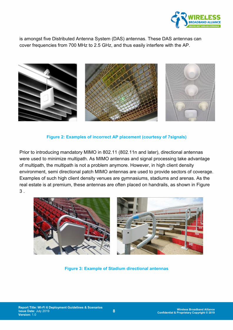
Figure 2 shows examples of a poor choice of AP placement. In the first picture AP is hanging from metallic surface. In the second picture, AP is against wire mesh. In the third picture, AP
Report Title: Wi-Fi 6 Deployment Guidelines & Scenarios Issue Date: July 2019 Version: 1.0
8 Wireless Broadband Alliance Confidential & Proprietary Copyright © 2019
is amongst five Distributed Antenna System (DAS) antennas. These DAS antennas can cover frequencies from 700 MHz to 2.5 GHz, and thus easily interfere with the AP.
Figure 2: Examples of incorrect AP placement (courtesy of 7signals)
Prior to introducing mandatory MIMO in 802.11 (802.11n and later), directional antennas were used to minimize multipath. As MIMO antennas and signal processing take advantage of multipath, the multipath is not a problem anymore. However, in high client density environment, semi directional patch MIMO antennas are used to provide sectors of coverage. Examples of such high client density venues are gymnasiums, stadiums and arenas. As the real estate is at premium, these antennas are often placed on handrails, as shown in Figure 3 .
Figure 3: Example of Stadium directional antennas

Report Title: Wi-Fi 6 Deployment Guidelines & Scenarios Issue Date: July 2019 Version: 1.0
9 Wireless Broadband Alliance Confidential & Proprietary Copyright © 2019
Aside from the high client density venues, directional antennas are used to provide coverage in tunnels, hallways and corridors, often in combination with omnidirectional antennas as shown in Figure 4:
Figure 4: Omni-directional (Ch 6, 11) and directional (Ch 1) antennas
Professional Design Tools need to define usage profiles for different deployment needs in terms of coverage and capacity, considering use-cases such as IoT, streaming video, VoIP and many others.
Any tool for RF design and planning should, at minimum, be able to generate predictions for signal propagation, co-channel interference (CCI), capacity, achievable data-rates heat-maps, along with compliance targets for pass/fail KPIs.
These predictions need to support new parameter values introduced by Wi-Fi6, namely for the Guard Interval, Symbol Duration, 1024 QuAM. These new values would have a positive impact on the average throughput and the maximum achievable data rate.
Additionally, owing to the BSS colouring capability of Wi-Fi 6, CCI predictions need to support taking the “colour” into consideration, which would allow denser design without compromising on CCI.
Moreover, a corresponding Bill-of-Materials needs to be provided for the final design in order to communicate the right components to support procurement and installation. This should, at minimum, include access points, controllers and cabling needs. It could also include switches, routers and racks needed to support the Wi-Fi wireless network LAN connectivity.
Report Title: Wi-Fi 6 Deployment Guidelines & Scenarios Issue Date: July 2019 Version: 1.0
10 Wireless Broadband Alliance Confidential & Proprietary Copyright © 2019
2.1.7. Post deployment survey to collect KPIs
Post deployment surveys are important to validate that the actual installation meets the design targets; the realities of the installation process (deviations from any predictive design) means that the intended RF designer’s vision is never applied at the venue.
This creates the need for tuning to the installed network; this could be as easy as changing some output power configuration on some of the access points or could necessitate a more costly intervention, like adding more access points or moving already installed access points to some other location. These interventions often require multiple iterations in order to meet the desired KPIs.
Post deployment survey provides the data to guide the tuning process in the hopes of minimizing costly iterations. Coverage strength is the main data that would help at this stage, while channel assignment could also provide insight into underperforming networks.
Ideally, a design tool that could take as input actual post deployment data and calibrate the design model could be used to shorten and optimize the tuning process further, minimizing the iterations needed.
2.2. Infrastructure SLAs
This section shall list all SLAs that the network infrastructure can be measured against. The goal is to identify the key SLAs without enforcing the thresholds for them as it is up to the Service Provider or the operator to figure out thresholds.
2.2.1. Bandwidth
All Wi-Fi 6 devices (AP and non-AP STA) are 2.4GHz only, 5GHz only, or dual band, although it operates in a single band at any point of time.
For single user (SU) transmissions and receptions in HE SU PPDUs within 2.4GHz and 5GHz bands, channel widths of 20MHz, 40MHz, 80MHz, and optional 160MHz are defined, excluding 40MHz channel width in 2.4GHz. If channel width of 160MHz is implemented, then the frames transmitted by an AP or a non-AP STA doubles the data rate with respect to frames that are transmitted with channel width of 80MHz.
In case of multi-user (MU) transmissions and receptions, narrow channel widths of 2MHz, 4MHz, and 8MHz are defined along with 20MHz, 40MHz, and 80MHz channel widths. The 256 tones or sub-carriers within an OFDMA PPDU in 20MHz channel width have multiple combinations of resource allocations: Nine 26 tones (equivalent to 2MHz) resource units (RUs), four 52 tones (equivalent to 4MHz) RUs, two 106 tones (equivalent to 8MHz) RUs, or a single 242 tones (equivalent to 20MHz) RU
Report Title: Wi-Fi 6 Deployment Guidelines & Scenarios Issue Date: July 2019 Version: 1.0
11 Wireless Broadband Alliance Confidential & Proprietary Copyright © 2019
2.2.2. Throughput (peak speeds)
The promise of Wi-Fi 6 is to provide 4 times higher throughput than the peak throughput (1Gbps) of 802.11ac. Due to the introduction of 1024-QAM, support of 8 spatial streams and short GI of 0.8us, the maximum (PHY) throughput is around 9.6Gbps in operational channel bandwidth of 160MHz. The equivalent throughput with 1 spatial stream support is limited to 1.24Gbps. The corresponding throughput value with 1024-QAM, 0.8us GI, and 1 spatial stream support ranges from 620Mbps in 80MHz, 300Mbps in 40MHz, and 150Mbps in 20MHz channel bandwidth.
On the other hand, maximum throughput of 15.44Mbps is achieved when a Wi-Fi 6 STA has a resource unit allocation of 2MHz (26 tones) channel bandwidth.
2.2.3. Range/Coverage (OFDMA related SLA)
Wi-Fi 6 improves performance at range in typical outdoor deployment scenarios. Three different mechanisms are explained further in section 2.2.12. The UL OFDMA power boosting feature referenced is also applicable for indoor operation.
Additionally, unlike its predecessor, Wi-Fi 6 is specified for 2.4 GHz. Using Wi-Fi 6 on 2.4 GHz may thus result in improved range at a given transmit power level. This is because of the more favorable free pathloss on 2.4 GHz as well as the lesser attenuation through some standard building materials.
2.2.4. Packet Loss
Packet loss might occur due to channel impairments or due to network congestion. In MU transmissions, packet loss might occur due to several reasons namely, inadequate packet extension in the DL MU PPDU or SU PPDU carrying a Trigger frame and time offset (maximum of SIFS+0.4us) and frequency offset (maximum of center frequency+350Hz) pre-correction errors in HE TB PPDU transmissions.
In case of inadequate packet extension in DL SU / MU PPDU, a STA that needs additional processing time might fail to decode the DL packet and hence either drop the packet, thereby resulting in re-transmissions or it might not be able to transmit its HE TB PPDU (in response to a Trigger frame) not knowing its assigned resource unit.
If even a single STA is unable to adhere to the maximum allowed time or frequency offset, then the AP will not be able to decode either of the set of HE TB PPDUs from multiple users in response to a Trigger frame. In other words, the entire UL OFDMA frame exchange will be regarded as corrupted and need retransmissions.
Report Title: Wi-Fi 6 Deployment Guidelines & Scenarios Issue Date: July 2019 Version: 1.0
12 Wireless Broadband Alliance Confidential & Proprietary Copyright © 2019
Desired values of 1-2% packet losses are sustainable, while greater than 10% packet loss may result in quality of service degradation.
2.2.5. End-to-end latency
This metric is measured as the total duration, starting from the time when a packet is queued in the transmit buffer of a STA to the time when the packet is received correctly at the intended receiver. A timestamp is generated by the STA when the packet is created and is included in the MAC header of the packet.
Scheduling the transmissions in MU PPDUs (UL / DL OFDMA or DL MU-MIMO) can achieve reduced end-to-end latency, due to the guaranteed medium access by the AP in scheduled periods of data exchange, removing the latency from EDCA-based channel contention or reducing collisions experienced by STAs.
2.2.6. Spectral Efficiency
Spectral efficiency is quantified in terms of link spectral efficiency or system spectral efficiency. Link spectral efficiency (bps/Hz) captures the quality of the link used for frame exchange between a single pair of devices. In MU scenarios, for example, DL/ UL OFDMA or DL MU MIMO-based transmissions, system spectral efficiency or area spectral efficiency (bps/Hz per unit area) should be used.
In other words, system spectral efficiency in MU scenarios is quantified as the maximum aggregated throughput or goodput divided by the channel bandwidth and by the area of coverage. This metric captures the effectiveness of DL or UL transmissions not only from a single user but from a group of users assigned resources in the MU PPDU.
Due to the preamble amortization over multiple users, the system spectral efficiency for DL or UL OFDMA PPDU is higher than in single user PPDUs with overhead of preamble or PLCP headers. For example, with 26 tone (2MHz) resource unit allocation, a maximum of 9 users can be assigned in 20MHz channel bandwidth or a maximum of 37 users in 80MHz channel bandwidth in a single MU frame exchange.
2.2.7. Spatial Re-use/Color codes
For the existing NAV (Network Allocation Vector) rule in Wi-Fi 5, a station updates its NAV based on the Duration field in any valid frame. Setting OBSS PD level to -72dBm, an intra-BSS device located in the OBSS with receiving OBSS signal strength from -82dBm to -72dBm can change from CCA busy to idle. However, if the device decodes the duration field correctly from the OBSS signal, the device cannot transmit for spatial re-use due to its higher NAV value.
Report Title: Wi-Fi 6 Deployment Guidelines & Scenarios Issue Date: July 2019 Version: 1.0
13 Wireless Broadband Alliance Confidential & Proprietary Copyright © 2019
The concept of the spatial re-use in Wi-Fi 6 is that when a station uses its OBSS PD level (e.g., -72dBm) for the OBSS signal, it should not update its NAV when receiving a valid duration field from the OBSS signal if the measured RSSI of the OBSS signal is less than the OBSS PD level. Spatial re-use is implemented by BSS coloring and two NAV timers. The BSS color in the SIG-A field allows devices to differentiate between intra-BSS frames and inter-BSS frames, and the use of the timers help identify when the medium is idle.
By using spatial re-use, network performance is improved because different access points on the same channel can be placed closer together and still transmit at the same time as long as the access points have different BSS colors.
2.2.8. Spatial Diversity
Spatial diversity refers to the use of multiple radio antennas to improve signal integrity and it has been introduced in Wi-Fi by MIMO and downlink MU-MIMO in Wi-Fi 4 and Wi-Fi 5, respectively. There are many potential benefits in increasing the number of spatial streams; for example, achieving higher throughput while communicating with a station, or achieving higher aggregate throughput while communicating with multiple stations in a MU-MIMO environment.
In Wi-Fi CERTIFIED ac, downlink MU-MIMO is an optional feature at both the access points and the stations. In Wi-Fi 6, however, transmission of downlink MU-MIMO is mandatory for the access points if the supported maximum number of transmit spatial streams is greater than or equal to 4, while the reception of full bandwidth downlink MU-MIMO is mandatory for the stations if the supported maximum number of spatial streams over all users is less than or equal to 4. Further, Wi-Fi 6 extends the maximum number of users supported for downlink MU-MIMO to 8 per resource unit.
In addition to the enhanced downlink MU-MIMO, uplink MU-MIMO is introduced in Wi-Fi 6 in which multiple stations are connected to the access point by sending acknowledgement response simultaneously, resulting in air time saving and improvements in network throughput.
2.2.9. Concurrent Users
The number of concurrent users should be clarified as the number of concurrent users per BSS, i.e., the number of active users that a BSS can support with general acceptable user experience, where an active user refers to a user who is transmitting to or receiving from the AP. For the purpose of discussion, assume that broadcast services are not relevant to this performance measure, due to the broadcasting nature of air media.
Report Title: Wi-Fi 6 Deployment Guidelines & Scenarios Issue Date: July 2019 Version: 1.0
14 Wireless Broadband Alliance Confidential & Proprietary Copyright © 2019
The number of concurrent users per BSS is an important parameter in Wi-Fi network deployment, which directly impacts on the number of BSSs and backhaul requirements for a given coverage and a set of expected applications of the Wi-Fi network.
There are multiple factors that determine the number of concurrent users per BSS, including the requirements of “general acceptable user experience” for the expected applications of the network, and the basic performance of the Wi-Fi APs and STAs, such as data rate and latency, etc.
Wi-Fi 6 will significantly improve the performance of the number of concurrent users with multiple specific design principles. For example, the underline standard for Wi-Fi 6, is targeted on at least 4 times improvement in the average throughput per station in a dense deployment scenario, where clearly the improvements on the average throughput per station help the number of concurrent users. The introduction of UL multiple user access, including both UL OFDMA and UL MU MIMO, will especially enable more concurrent accesses to the radio resources. Moreover, the introduction of scheduling based medium access will fundamentally change the contention condition for a much better support to concurrent users.
2.2.10. Power Consumption Measurements
Target Wake Time (TWT) is a power-efficient scheduling mechanism introduced in Wi-Fi 6 in order to deliver traffic in intervals of “wake” times that are pre-negotiated between a TWT requesting STA (i.e., a client device) and a TWT Responding STA (i.e., an AP). These wake times initiated by a TWT requesting STA are driven by applications (e.g., video streaming) supported and device-specific (e.g., IOT), but it is up to the TWT Responding STA to either accept, suggest, or reject the specific request. The STA remains in doze state in between the negotiated time intervals. Ideally, an AP shall not transmit any data to an STA outside the negotiated TWT wake intervals.
Based on deployment scenarios and user experience (video streaming or VoWi-Fi), the TWT Responding STAs could be configured by the Network Controller / Operator to allocate different priority levels to wake times requested from different categories of TWT Requesting STAs.
The TWT mechanism was originally introduced in the IEEE 802.11ah amendment. Wi-Fi 6 adopted this mechanism and defined a triggered operation with the TWT service periods (SPs). Multi-user transmissions - namely, UL and DL OFDMA and DL MU MIMO - are predominantly used within the wake intervals.
Individual TWT is one of the triggered operation mode that allows STAs in doze state to wake up in negotiated wake intervals for exchange of traffic between an AP and a STA. This mechanism allows reduced power consumption for an STA since it wakes up in targeted
Report Title: Wi-Fi 6 Deployment Guidelines & Scenarios Issue Date: July 2019 Version: 1.0
15 Wireless Broadband Alliance Confidential & Proprietary Copyright © 2019
wake intervals and returns to doze state outside of these negotiated intervals. Additionally, the triggered operation reduces the overhead of contention and collisions incurred due to the conventional EDCA-based channel access mechanism.
Individual TWT defines two different types of triggered operation namely, announced TWT and unannounced TWT. In announced TWT operation, an STA is required to announce its presence in order to retrieve the DL data buffered at the AP. On the other hand, unannounced TWT operation allows the AP to transmit DL traffic to STAs that are active within the targeted wake times.
2.2.11. Traffic Prioritization
802.11 specifications allow both Terminal and Access Point Wi-Fi devices to prioritize traffic of different flows (both Ethernet and IP traffic) by associating it with different access classes. A different QoS may be applied for all of the flows belonging to a specific access class.
In the context of using 802.11 technology as an access to 5G core services, a common use case for supporting multiple IPSec tunnels (security associations) for varying traffic flows is needed to accommodate the QoS requirements of those varying flows. A new classifier type has been introduced allowing to associate for QoS purposes IP flows identified and matched using any fields of any protocol that is specified within an IP header of either IPv4 or IPv6 type.
The mechanism can be applied to any 802.11 technology and for any IP based feature including VoWLAN and access for 4G/5G services.
2.2.12. Outdoor Performance
11ax provides gains over 11ac in an outdoor channel with large delay spread, thanks to the longer guard interval / cyclic prefix. These longer values are one of the benefits of moving to 4x longer OFDM symbol.
UL OFDMA closes UL link budget due to power boosting of narrow 2MHz channels. (about 10dB gain.)
At moderate Doppler speeds (e.g. vehicular mobility), 11ax introduces a "midamble" which enables channel re-estimation in the middle of longer PPDUs - this is particularly necessary when link is strong enough to support higher MCS. Simulation results show use of midamble support speeds of up to 60 km/h with minimal overhead.

Report Title: Wi-Fi 6 Deployment Guidelines & Scenarios Issue Date: July 2019 Version: 1.0
16 Wireless Broadband Alliance Confidential & Proprietary Copyright © 2019
2.3. Seamless Mobility
Mobility can be defined as movement by a Wi-Fi station from the coverage area of one AP to the coverage area of another AP where the station takes steps to disconnect from the old AP and connect to a new one. Roaming occurs in Wi-Fi when an established Wi-Fi network association is transferred from one access point to another access point within the same SSID without losing connection. Roaming is seamless when the network association transfer occurs so that minimal User Experience impact is detected. For voice-over-Wi-Fi calls, this transition needs to be in the 100ms range or less in order for the transition to appear seamless.
Mobility is entirely controlled by the station in Wi-Fi. Over the years, Wi-Fi has added mechanisms that make it easier for the station to make these decisions. Using 802.11k the station can request AP its list of neighbors. This will reduce the time it takes for the STA to decide which one to move to next. Using the 802.11v BSS Transition Management mechanism the AP can request STA to move to another AP. It is still up the STA whether to follow the request. 802.11v also has facilities to provide information to the STA about the traffic load of the surrounding APs.
Wi-Fi also has built-in improvements around making the roam event faster, once the station decides to do it. In the early days of Wi-Fi the roam event was a fairly simple event, consisting of only four messages. As additional features were added (802.11i and 802.11x, etc) the number of messages increased and the roam event became slower to perform and lost some of its seamlessness. 802.11r or Fast BSS transition was introduced to simplify the message exchange at the time of the roam event and thus make the roam event faster. This is achieved by performing an initial handshake before the STA roams to the target AP. Initial handshake allows the STA and the APs to do a Pairwise Master Key calculation in advance. Once the STA moves to re-association request or response exchange with the new AP the PMK keys are applied to the client and AP. This allows fast transitions between APs without the need for re-authentication at every AP.
802.11ai or Fast Initial Link Setup is an upcoming function that improves the speed of initial connect to Wi-Fi achieving a secure link setup in less than 100ms. This will speed up transitions into Wi-Fi but will not address Wi-Fi to Wi-Fi mobility.
2.4. Preparing for Co-existence
This section covers topics that related to the co-existence of Wi-Fi 6 with other licensed and unlicensed technologies in a given network setup.
Report Title: Wi-Fi 6 Deployment Guidelines & Scenarios Issue Date: July 2019 Version: 1.0
17 Wireless Broadband Alliance Confidential & Proprietary Copyright © 2019
2.4.1. Backward compatibility with previous Wi-Fi generations
Wi-Fi 6 supports both 2.4 and 5 GHz wireless devices, so 802.11a/b/g/n/ac devices will be able to co-exist with Wi-Fi 6 devices. A Wi-Fi 6 device supports all the mandatory modes of 802.11a/g/n and 802.11ac. For backwards compatibility, Wi-Fi 6 radios also support OFDM and HR-DSSS.
An Wi-Fi-6 AP can communicate with legacy (IEEE802.11a/b/g), HT (IEEE802.11n) and VHT (IEEE802.11ac) clients. On the other hand, an Wi-Fi-6 client can communicate to legacy or HT or VHT AP. Wi-Fi 6 is optimally designed for forward and backward compatibility. Therefore, the emergence of Wi-Fi 6 clients will not necessarily require up-gradation of the existing infrastructure.
The preamble of the Wi-Fi 6 formatted packet is an expansion of the legacy 802.11a/g formatted packet. It is used for synchronization between transmitting and receiving radios and consists of two parts: legacy and high efficiency (HE). The legacy preamble is easily decoded by legacy stations (STAs) and is included for backward compatibility. This expansion allows the existing CCA mechanisms, used in 802.11a/g/n and 802.11ac devices to continue in the Wi-Fi 6 networks. As soon as these devices receive Wi-Fi 6 preamble, they can retrieve the duration of the PPDU and can account that time request. In Wi-Fi 6 also, PPDUs are followed by an ACK or Block ACK in legacy format PPDU, so compatibility with existing devices is assured and all can recognize the time commitments established before pursuing to contend and transmit. In case of hidden node, a device hears the Wi-Fi 6 PPDU but can not hear the station transmitting ACK or Block ACK. In this scenario, the observing station must still wait for extra time and allow transmission of the expected Ack or Block Ack, this will reduce the doubt of collision. This extra wait time is called EIFS.
Existing RTS/CTS or CTS-to-self mechanisms are followed to protect transmission of longer PPDUs by Wi-Fi 6 devices, so that the performance of 802.11 a/b/g/n and 802.11 ac devices will not be affected by Wi-Fi 6 devices. In case of multi user operation, Wi-Fi 6 adds capability of MU-RTS PPDU which is confirmed with simultaneous CTS PPDUs from multiple STAs. This scenario overcomes the inherent inefficiency of single user RTS/CTS in 802.11ac networks and adds protection to Wi-Fi 6 transmissions.
2.4.1.1. Co-existence with Radar
Wi-Fi systems may coexist with radar system as per the region-specific regulatory rules. Wi-Fi uses the Dynamic Frequency Selection (DFS) mechanism to avoid operating in the same channel as radar.
Report Title: Wi-Fi 6 Deployment Guidelines & Scenarios Issue Date: July 2019 Version: 1.0
18 Wireless Broadband Alliance Confidential & Proprietary Copyright © 2019
During initial and normal operations, AP should perform a Channel Availability Check (CAC) to ensure that there is no radar operating on its channel. Upon detection of radar, it discontinues the operation, marks the channel as unavailable for a Non Occupancy Period (NOP) and should move to another available channel.
CAC Time, Channel Move Time and NOP should be configured as per the regulatory guidelines of the specific region.
2.4.1.2. Co-existence Satellite
C-band communication satellites use the band of frequencies as allocated in World Radio communication Conference (WRC). Its range overlaps the ISM band of 5.8 GHz used for Wi-Fi deployment. In order to coexist with this incumbent , Wi-Fi has to comply with the power limitations for World and Region specific regulatory rules. Transmit Power Control (TPC) mechanism adhering to regulatory rules can be employed for coexistence. For eg; FCC part 15 Subpart E specifies that the maximum Effective Isotropic Radiated Power (EIRP) at any elevation angle above 30 degrees as measured from the horizon must not exceed 125 mW (21 dBm).
3. Deployment Scenarios
3.1. Public Venues
This vertical market consists of public environments such as airports, convention centers, malls, and other public open architectures. In these venues, population density is quite high, and the expectation is that the BSS will need to support a high number of users. The demand in these venues for bandwidth continues to increase, with the requirement for video and streaming applications driving this demand.
Wi-Fi 6, with its modifications to the standard to improve the efficiency of the spectrum, will serve this vertical market well by allowing concurrent usage and supporting the continual increase for bandwidth per user. As these venues also see a rise in voice traffic (carrier offload) on the Wi-Fi networks, Wi-Fi 6’s ability to handle latency more efficiently will also prove beneficial to this vertical market.
3.2. Entertainment/Stadiums
The stadium venue is by far the most dense of the deployments. Care must be taken to properly align the coverage area of each access point to minimize contention with the adjacent cells, and to minimize noise. As with public venues, the demand for bandwidth continues to increase, as video and picture upload/download continue to proliferate the

Report Title: Wi-Fi 6 Deployment Guidelines & Scenarios Issue Date: July 2019 Version: 1.0
19 Wireless Broadband Alliance Confidential & Proprietary Copyright © 2019
network. In past stadium builds, it was common to limit the end user to speeds of 2-5 Mpbs each, but the trends show that this value is increasing, with some stadiums completely lifting any cap for bandwidth per user. Once again Wi-Fi 6’s use of OFDMA, MU-MIMO both on the UL as well as the DL will serve well for this type of deployment given the increase demand for video upload from the user.
Reliable connections at scale, and consistent latency at scale; controlling retransmissions. Increases in efficiency will reduce noise and contentious environment, driving to 80% airtime efficiency.
3.3. Residential/MDU
This vertical covers everything from military barracks to college campus housing to townhome and condominium complexes. While the user density requirements for this vertical may not be as strong, the requirement for bandwidth continues to increase. As service providers continue to increase the backhaul egress internet speeds, the demands for the Wi-Fi performance will match those increases. This may be the best vertical to take advantage of QAM-1024, with the end user being potentially close to the access point in order to achieve this high data rate.
This vertical market also will see extensive use of latency sensitive applications such as gaming and voice traffic, where improvements on the spectrum provided by Wi-Fi 6 can be appreciated.
Residential Wi-Fi encompasses a wide variety of deployments from single family units (SFU) to multi-dwelling units (MDU) and college campus housing. The wireless conditions significantly vary with each deployment based on unit type, floor plan, and construction materials. The residential environments, especially SFUs and MDUs, share a growing diversity of clients and applications, and the presence of many legacy devices.
The user density for residential deployments is not as strong as the enterprise or stadium scenario; however, the requirement for bandwidth continues to increase steadily. In the United States, for example, cable gigabit services are available to 80% of housing units and the cable industry has recently launched the 10G initiative. Given the huge capital investment required to upgrade the networks, residential subscribers must experience the significant enhanced speed on their wireless network.
Dual-band operation is becoming the de-facto configuration in residential deployment. While the 2.4 GHz band is often congested and prone to non-Wi-Fi interferences, this band is required to support legacy clients (802.11b/g/n) and is better suited for applications with best effort QoS. Wi-Fi 6 features including OFDMA, TWT, and ER can support the massive

Report Title: Wi-Fi 6 Deployment Guidelines & Scenarios Issue Date: July 2019 Version: 1.0
20 Wireless Broadband Alliance Confidential & Proprietary Copyright © 2019
deployment of smart home devices characterized by low data rates with small packet sizes, low power consumption, and the need for increased range.
The 5 GHz band remains the preferred band to serve high-bandwidth applications, especially managed services (IPTV/STB) and other video applications. Wi-Fi 6 enhanced MU-MIMO can increase capacity when serving a small number of high bandwidth clients. Users close to the AP can also achieve higher data rate with 1024 QAM. This band also serves latency sensitive applications including online gaming and mixed /virtual reality. By scheduling more frequent transmit opportunities, Wi-Fi 6 OFDMA can help reduce latency. The efficiency of the AP scheduler, which is not defined by the standard, will play a key role to achieve the best performance. In addition, the support of WMM (802.11e), which requires the marking of the traffic (802.1p or DSCP), is needed to guarantee appropriate QoS. While managed services can set up appropriate QoS, many applications and clients lack the ability to properly mark the traffic which may result in poor user experiences. Application detection and traffic marking should be implemented on the wireless gateway to support, at least, downlink QoS.
The 6 GHz band, if/when available, will extend the 5 GHz band to deliver the true capacity needed for gigabit broadband access. Due to the absence of legacy devices in this band, the efficiency of Wi-Fi 6 will be able to serve next generation mission critical applications.
The type of residential unit dictates the deployment scenario. Managed Wi-Fi such as MDUs or college campus housings have similarities with the enterprise use case. They benefit from comprehensive site surveys, channel planning, and design services to meet specified SLAs. The availability of wired backhauls (i.e. Ethernet) provides flexibility for optimal AP placements and the support of higher data rate.
Non-managed MDUs, however, are the most challenging residential environment. Non managed MDUs are characterized by numerous uncoordinated and overlapping APs, ever-changing channel configuration and a higher client density. SFU environments experience these poor channel conditions to a lesser extent but are more prone to coverage issues.
Poor AP placements impact both coverage and throughput. APs are usually best positioned in the center of the unit or in the living room where most of the traffic is happening. In single detached homes with large or multi-level floorplan, one AP may not provide an acceptable coverage. For this type of unit, whole home coverage with a consistent performance relies on a multi-AP (extenders/mesh) architecture. A Multi-AP architecture can also add additional system capacity when a dedicated wired or wireless backhaul link is implemented. Wi-Fi CERTIFIED EasyMeshTM facilitates the deployment of Multi-AP architecture. It provides the necessary framework for client link management (client steering, band steering) and defines a communication protocol to enable easy onboarding, provisioning, control, and automated
Report Title: Wi-Fi 6 Deployment Guidelines & Scenarios Issue Date: July 2019 Version: 1.0
21 Wireless Broadband Alliance Confidential & Proprietary Copyright © 2019
management of APs. The support of Wi-Fi CERTIFIED Agile MultibandTM and Wi-Fi CERTIFIED Optimized ConnectivityTM also provide the required interoperability for client steering and fast roaming.
The deployment of RRM solutions is also key to increase visibility into the wireless network, to mitigate issues related to interference and congestion, and to proactively manage the wireless resources. RRM features include:
- Dynamic channel selection to allocate the optimal radio channel at start-up and monitor the RF environment to adapt to the channel conditions.
- The use of DFS channels when possible, especially for managed video services, to increase the number of usable channels and lower interference
- Dynamic power control to adjust power levels for “good neighbor” behavior and to optimize range
In non-managed MDU scenarios, Wi-Fi CERTIFIED EasyMeshTM provides the necessary KPIs (Wi-Fi CERTIFIED Data ElementsTM) to support local or remote RRM resources in single-AP architecture. Centralized (cloud based) RRM solutions can effectively manage the wireless network across multiple MDU or SFU units as many residents subscribe to the same service provider.
For new homes, Wi-Fi CERTIFIED Home Design™ brings enterprise design best practices to the homebuilding industry. The certification program defines design guidelines to provide the best connectivity, performance, and coverage throughout the home.
The WBA In-Home project further addresses the challenges of deploying residential Wi-Fi including device onboarding and end-to-end security, and recently issued an In-Home Wi-Fi Industry Guidelines white paper.
3.4. Smart Cities/IoT
This may be one of the fastest growing market verticals, adding Wi-Fi capable devices at an exponential rate. The speed and bandwidth demand for this market on a per STA basis remain quite small in comparison to the other verticals. However, the sheer number of connections to the BSS will certainly be high. The use of the smaller RUs (down to 2MHz) within the Wi-Fi 6 specification can be advantageous in these deployments, maximizing the efficiency of the spectrum, and ensuring timely communication for this wave of use cases.
Similar to other deployment scenarios above, Wi-Fi 6’s new capabilities have significant benefits that impact best practices for deployment in Smart Cities. The increased capacity of Wi-Fi 6 networks is a key feature for Smart Cities deployments, where the bandwidth demand
Report Title: Wi-Fi 6 Deployment Guidelines & Scenarios Issue Date: July 2019 Version: 1.0
22 Wireless Broadband Alliance Confidential & Proprietary Copyright © 2019
for each client device is comparatively low (compared to other verticals), but the number of connections can be very high. However, the increased throughput capabilities of Wi-Fi 6 also come into play when considering wireless backhaul scenarios for the Smart Cities network. Finally, the features to enable better standby power consumption and increased range are important factors for supporting community IoT devices on the shared infrastructure.
3.4.1. Site planning
With increased capacity and fairness for a large number of clients on Wi-Fi 6, congestion planning can be simplified for Smart City deployments. However, care must be taken during the near-term period of transition. Since Wi-Fi 6 clients have started shipping as early as Q1 2019, the transition of client capabilities in the field has already begun and should be expected to continue rapidly. On a Wi-Fi 6 infrastructure, as the percentage of Wi-Fi 6 capable clients increases, all clients will gain the benefits of the capacity improvements.
As the client mix of Wi-Fi 6 increases, the benefits of the new frequency re-use features will also become a significant factor, allowing access points to be moved closer, thus increasing the overall network capacity with a higher density of access points at a given client to access point ratio.
Thus, Smart City site planners may want to consider a transition plan, where access points can be moved into a denser configuration – or additional access points be added – over time. This will allow the network to adapt to the increased Wi-Fi 6 client capability, simultaneously with increasing the overall bandwidth to match the ever-increasing demand from users.
3.4.2. Backhaul
With the increased client capacity on each access point, Wi-Fi 6 can add new challenges for the backhaul technology that connects those access points to the Internet and other services. In scenarios where the backhaul is over wired, or other technology wireless connections, the increased demand in backhaul bandwidth must be factored into deployment operations.
Luckily, Wi-Fi 6 also offers higher peak throughput on specific links, which offers the option of using Wi-Fi as a wireless backhaul for the Wi-Fi 6 access point deployment. Wi-Fi 6’s higher peak data rates, especially on stable and reliable links like a fixed-point backhaul, can be combined with its ability to separate and prioritize traffic streams, thus making the best use of the bandwidth to ensure highly responsive packet delivery to response-time critical applications such as safety and augmented reality, and high burst throughput to applications such as web browsers and streaming media.
Report Title: Wi-Fi 6 Deployment Guidelines & Scenarios Issue Date: July 2019 Version: 1.0
23 Wireless Broadband Alliance Confidential & Proprietary Copyright © 2019
3.4.3. Community IoT
A key aspect of Smart Cities is the deployment of many connected IoT devices for community safety and services. Due to Wi-Fi 6’s new capabilities to support many clients simultaneously, this can be accommodated without significant re-design of the deployment model, if the IoT devices are also upgraded to Wi-Fi 6 client capability. As noted above, however, for those IoT devices that are not upgraded (due to cost or access), as other clients on the wireless network are upgraded, even the “legacy” devices will receive benefit from the increased client capacity features.
An extended range capability is also part of Wi-Fi 6, allowing IoT devices to be placed nearer the edges of coverage of the Wi-Fi network and still operate efficiently. This again relieves the design of the deployment from the challenge of ensuring close coverage to all the various IoT devices, which are typically spread throughout the community areas. To get the advantages of the extended range, however, the IoT devices must also be Wi-Fi 6 capable.
Finally, Wi-Fi 6 also provides improved power saving features, especially targeted at IoT devices. As with the extended range feature, it is important that the IoT devices are also Wi-Fi 6 capable to enable these new power saving modes.
3.4.4. IoT deployment benefits
There are unique requirements for the deployment of IoT devices that Wi-Fi 6 can provide a significant benefit for:
Low power consumption. As discussed in the Introduction, low power consumption is an important requirement for IoT in small mobile devices. Wi-Fi 6 provides an important low power feature, namely target wake time (TWT), which allows a client (station) device to stay inactive for a long period of time and wake up at time slots that are prescheduled with the associated access point. In particular, the use of TWT service period provides significant power saving over the conventional unscheduled service period; while the uplink scheduling of Trigger frame can be set up between a station and the associated access point using TWT operation to save power and reduce collisions.
Extended range. The extended range requirement of a few IoT verticals currently being discussed by the industry can also be satisfied by Wi-Fi 6. In particular, the use of 26-tone 2 MHz resource unit within a 20 MHz channel, which is the minimal resource unit allocation available, allows for a more granular allocation of resources to multiple stations, which result is better noise tolerance and hence larger link budget. Wi-Fi 6 also includes a number of features that are useful for long range point-to-point operation, including the longer cyclic prefix options of 1.6 microseconds and 3.2 microseconds that would be used to combat long
Report Title: Wi-Fi 6 Deployment Guidelines & Scenarios Issue Date: July 2019 Version: 1.0
24 Wireless Broadband Alliance Confidential & Proprietary Copyright © 2019
delay multipath, the use of an extended range beacon that provides additional link budget for downlink transmissions to compensate for the link budget imbalance between downlink and uplink.
Secure and easy installation. WPA3 and enhanced open, which are the state-of-the-art security, is a pre-requisite for Wi-Fi 6 deployment. Installation of Wi-Fi 6 IoT devices can also leverage Wi-Fi CERTIFIED Easy Connect, which simplifies the provisioning and configuration of the IoT devices and enhances the user experience of connecting devices to Wi-Fi networks, while simultaneously incorporating the highest security standards.
Reliability. Wi-Fi 6 is capable of handling a large number of users in a large scale IoT deployment including latency sensitive applications. Wi-Fi 6 moves decision making logic from stations to their associated access point that determines which station to transmit. Such scheduling capability is important for achieving consistency while improving effective throughout.
3.5. Enterprise WLANs
Wi-Fi 6 is set to deliver key new capabilities that will impact the deployment of Wi-Fi by enterprises. With a focus on improving user experience in dense deployments, both indoors and outdoors, the increased user throughputs available with Wi-Fi 6 equipment will drive an evolution in enterprise WLAN architecture. The significant decision-points related to deployment scenarios can be categorized into: requirements and capabilities analysis, planning access point placement, and identifying appropriate supporting infrastructure upgrades.
3.5.1. Requirements and capabilities - Identifying important Wi-Fi 6 features for enterprise deployments
When planning access point locations, engineers should consider the evolving requirements of their user population, and how they wish to make use of the new capabilities available in Wi-Fi 6:
• Improved performance in buildings with high network capacity requirements. Wi-Fi 6 frequency re-use features allow closer access point spacing for higher aggregate capacity over a given floorplan.
• Better capacity and fairness with large numbers of clients constrained to a small area, as in a classroom, university lecture hall or sports stadium. Enhanced multi-user performance increases network capacity and allows more control from the infrastructure to balance loads across access points and frequency bands, and to tune network performance.
Report Title: Wi-Fi 6 Deployment Guidelines & Scenarios Issue Date: July 2019 Version: 1.0
25 Wireless Broadband Alliance Confidential & Proprietary Copyright © 2019
• Strong QoS capabilities, where different classes of traffic – or individual clients or streams – can be isolated from other traffic and assigned robust service-level guarantees. The ability to mix high- and low-bandwidth traffic while maintaining SLAs allows a single enterprise WLAN to serve employee, IoT, business and guest traffic with greater determinism than ever before.
• Extended range, particularly outdoors, enables improved pan-campus coverage from fewer access point locations. Wi-Fi 6 will accelerate the established trend to build out Wi-Fi beyond isolated building-scale networks to campus-wide seamless coverage.
• Wi-Fi 6 features for improved range and battery life, particularly at low rates, will accelerate penetration of Wi-Fi connected IoT devices and allow IT groups to support Wi-Fi IoT devices introduced by other departments, which formerly required dedicated gateways.
If the WLAN to be upgraded is Wi-Fi 4 (802.11n), users will experience an immediate improvement in performance, as the installed base of Wi-Fi 5 (802.11ac) client devices will be able to operate at higher data-rates. The benefits of an infrastructure upgrade from Wi-Fi 5 (802.11ac) to Wi-Fi 6 will ramp up as commercially-available devices penetrate the installed base, starting in early 2019.
3.5.2. Planning access point placement and upgrade sequencing for Wi-Fi 6
The requirements above can be mapped to decisions on the best strategy for introducing Wi-Fi 6 access points in an existing enterprise WLAN.
Different approaches to upgrading a campus include advancing building-by-building, starting with those best placed to benefit from Wi-Fi 6 features, or focusing specifically on the micro-environments such as lecture halls and research labs where the high-performance characteristics of Wi-Fi 6 can make an immediate improvement. The decision on technology type (e.g. when and where Wi-Fi 6 will be appropriate) should consider not just today’s performance requirements, but future requirements and the expected life of the technology cycle.
When upgrading existing WLANs to Wi-Fi 6, enterprises may find that optimum access point spacing and placement differs from existing locations. However, the decision to move access points must be balanced against the cost of re-configuring cabling to reach the new locations. Many enterprises will choose to replace access points in-situ unless they are able to bundle the Wi-Fi 6 upgrade with cabling projects, or are installing in a greenfield site.
Many of the new Wi-Fi 6 access points incorporate other radio technologies such as Bluetooth (BLE) and Zigbee, allowing a Wi-Fi 6-based infrastructure to support many IoT applications for smart buildings. Access point placement should be planned with these radio technologies in mind, in addition to Wi-Fi.
Report Title: Wi-Fi 6 Deployment Guidelines & Scenarios Issue Date: July 2019 Version: 1.0
26 Wireless Broadband Alliance Confidential & Proprietary Copyright © 2019
3.5.3. Associated infrastructure upgrades
Wi-Fi 6 access points are plug-and-play replacements for older generations: they will function on the existing edge switches, power and backhaul (Ethernet) facilities used for older access points. But for full Wi-Fi 6 performance, it may be necessary to consider upgrading this infrastructure.
The Wi-Fi 6 upgrade wave will drive further adoption of high-speed Ethernet. The new access points support IEEE 802.3bz-defined 2.5BASE-T and 5GBASE-T Ethernet using Cat5e and Cat6 twisted pair cables. Enterprises may decide that an upgrade project for Wi-Fi 6 is a suitable juncture for related upgrades of switch ports and wiring infrastructure.
From a power perspective, whereas some Wi-Fi 5 (802.11ac) access points can be powered using 802.3af defined power-over-Ethernet, the shift to Wi-Fi 6 is expected to drive requirements for higher power draw using the 802.3at (PoE+) standard. Moreover, some multi-radio Wi-Fi 6 access points may require the higher power available with 802.3bt (PoE++) for full-function operation.
These increasing demands for high-bandwidth, high-power connections for multi-radio Wi-Fi 6 access points, along with continuing retirement of wired connectivity to desks and workstations provide an opportunity to re-configure wiring closets, reducing the number of network edge ports while increasing their capability.
4. Business Advantages & Case Studies
4.1. Ecosystem
Backward compatibility is essential for many legacy devices which still operate in 2.4 GHz, particularly in healthcare and industrial automation, as vendors in these industries tend to move slowly to update their devices to the latest Wi-Fi standards. Wi-Fi 6 supports both 2.4 and 5 GHz wireless devices, so 802.11a/b/g/n devices will be able to run on Wi-Fi 6 Wi-Fi networks. When there are more legacy clients associating to the Wi-Fi-6 AP, it should not be configured in wider channel bandwidth. For example, if 11ax AP is configured to operate in 80 MHz channel, and there are many legacy clients (802.11 a/b/g), in this case, the AP will operate in 20 MHz channel most of the time to serve legacy clients and in turn 80 MHz channel bandwidth will not be used very efficiently.
When there is a scenario where 802.11ac and Wi-Fi 6 clients are in larger numbers, then Wi-Fi-6 AP may be configured with MU-MIMO feature enabled to improve network utilization and to provide significantly higher data throughput. However, this feature should be disabled in scenario where many legacy and HT (802.11n) clients are present as these clients do not support MU-MIMO feature.

Report Title: Wi-Fi 6 Deployment Guidelines & Scenarios Issue Date: July 2019 Version: 1.0
27 Wireless Broadband Alliance Confidential & Proprietary Copyright © 2019
There is no need to configure anything special to enable backward compatibility. When there is less or no legacy clients present, legacy mode may be disabled altogether to improve efficiency of an Wi-Fi-6 AP as backward compatibility comes with an overhead cost, and turning off older modes can boost performance. The same way HT or VHT modes may also be switched off as per the scenario. This should be an optional feature.
4.2. Case Study (Mettis Aerospace)
Wireless Broadband Alliance and Mettis Aerospace Announce World’s First Wi-Fi 6 Industrial Enterprise and IoT Trial:
The Wireless Broadband Alliance, a leading organization in support of the adoption of next generation Wi-Fi services across the Wi-Fi ecosystem, has announced the world’s first Wi-Fi 6 Industrial Enterprise and IoT trial, as part of its ongoing Wi-Fi 6 program. Mettis Aerospace, a designer and manufacturer of precision-forged, machined and sub-assembled components, primarily for the aerospace and defense industry, will work with WBA members to test several use cases* on a Wi-Fi 6 network at its 27-acre West Midlands facility. The trial, the first of a series of global trials, will enable the use of augmented reality, real-time monitoring of equipment, and a host of other applications in an enterprise network environment designed to digitize Mettis’ production line. Mettis Aerospace is a key supplier for organizations like Airbus, Boeing and Rolls-Royce.
The Mettis Aerospace environment is challenging from a connectivity perspective, with a large geography to be covered, and industrial radio interference that can disrupt signals. Some applications will require high bandwidth, others low latency and mission critical applications need clear prioritization for data. Wi-Fi 6 is well-positioned to support the provision of cost-effective enterprise-level connectivity in this industrial environment, to these standards using the latest security capabilities.
The West Midlands region, under the leadership of the Worcestershire Local Enterprise Partnership, was selected to be the UK’s 5G Testbed for manufacturing and security by the UK Government’s Department for Digital, Culture, Media & Sport. This trial will demonstrate the role that Wi-Fi 6 has to play in the broader 5G ecosystem.
Report Title: Wi-Fi 6 Deployment Guidelines & Scenarios Issue Date: July 2019 Version: 1.0
28 Wireless Broadband Alliance Confidential & Proprietary Copyright © 2019
The trial is being managed by the WBA and Mettis Aerospace, and supported by WBA members including British Telecom, Boingo, Broadcom, BSG Wireless, CableLabs, Cisco, HPE Aruba and Intel. It is scheduled to launch in the second half of 2019.
* Use cases under consideration include multi stream live video monitoring; real time energy monitoring; ultra-reliable low latency communications with sensors on critical systems and augmented reality for trouble shooting.
4.3. Case Study (Boingo Wireless)
Boingo Deploys Wi-Fi 6 at John Wayne Airport. Commercial Trial Marks Major Milestone for Airport Connectivity in the 5G Era:
Boingo Wireless, has announced the successful deployment of Wi-Fi 6 at John Wayne Airport (SNA) in Orange County, Calif. The launch is part of a commercial trial to test next-generation Wi-Fi capabilities and marks the first known Wi-Fi 6 deployment at a major airport.
“Wi-Fi 6 is a strategic pillar of Boingo’s technology roadmap to elevate wireless performance and equip airports and other large venues with connectivity solutions for the 5G world,” said Dr. Derek Peterson, chief technology officer, Boingo. “It meets key 5G requirements to power a broad range of connected use cases in dense environments with greater capacity, speed and scalability. We’re pleased to be among the first to put Wi-Fi 6 in action and work alongside the team at John Wayne Airport to move the technology from lab to real-world launch.”
Wi-Fi 6 is a new industry standard that was developed to advance Wi-Fi capabilities to effectively handle growing traffic demands. It is based on the Wi-Fi 6 specification and introduces new features to deliver faster speeds, higher density and faster throughput. Boingo deployed Cisco Wi-Fi 6 technology in SNA’s administration building. To test the network, Samsung Electronics provided SNA staff with early release Samsung Galaxy devices with Wi-Fi 6 chipsets. The Samsung Galaxy S10, which launched in February 2019, is the first family of smartphones with Wi-Fi 6 support. Staff used the Galaxy devices to carry out day-to-day administrative tasks and stream high bandwidth content, experiencing Wi-Fi 6’s high data rates and ultrafast speeds firsthand.
Report Title: Wi-Fi 6 Deployment Guidelines & Scenarios Issue Date: July 2019 Version: 1.0
29 Wireless Broadband Alliance Confidential & Proprietary Copyright © 2019
“This trial is part of our commitment to innovation and adopting technologies that are essential to providing a superior guest experience,” said Barry Rondinella, Airport Director, John Wayne Airport. “The Wi-Fi 6 network impressed our team, giving us wireless connectivity with no lag, no buffering and incredible speeds.”
SNA recently ranked as the highest rated airport by J.D. Power for customer satisfaction among large airports in North America for the second consecutive year. It was also voted #4 on Travel + Leisure’s “10 Best Domestic Airports” list.
Boingo and SNA are continuing their trial, exploring new use cases to realize the full potential of Wi-Fi 6 in airports.
5. Guidelines Maintenance Process
WBA is committed to maintain these guidelines aligned with latest developments, and as a result, industry wide feedback and participation is most welcome.
By nature, it is expected these guidelines will evolve as the technology matures, fields trials are executed, and deployments grow.
The project leadership and editorial team in conjunction with WBA Program Management Office guarantee all documentation update requests to reflect any of the latest assumptions are considered. Updates follow regular technical activities approval process.
For more information please contact: [email protected].
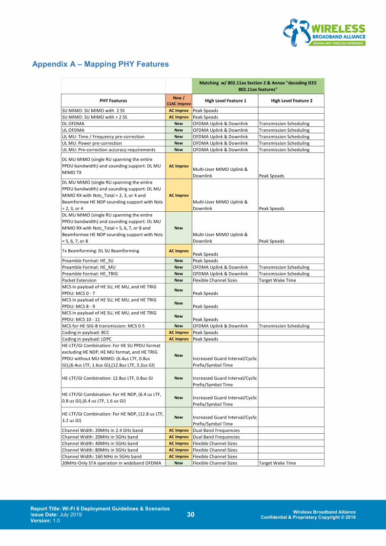
Report Title: Wi-Fi 6 Deployment Guidelines & Scenarios Issue Date: July 2019 Version: 1.0
30 Wireless Broadband Alliance Confidential & Proprietary Copyright © 2019
Appendix A – Mapping PHY Features
PHY Features New / 11AC Improv
High Level Feature 1 High Level Feature 2
SU MIMO: SU MIMO with 2 SS AC Improv Peak SpeadsSU MIMO: SU MIMO with > 2 SS AC Improv Peak SpeadsDL OFDMA New OFDMA Uplink & Downlink Transmission SchedulingUL OFDMA New OFDMA Uplink & Downlink Transmission SchedulingUL MU: Time / Frequency pre-correction New OFDMA Uplink & Downlink Transmission SchedulingUL MU: Power pre-correction New OFDMA Uplink & Downlink Transmission SchedulingUL MU: Pre-correction accuracy requirements New OFDMA Uplink & Downlink Transmission Scheduling
DL MU MIMO (single RU spanning the entire PPDU bandwidth) and sounding support: DL MU MIMO TX
AC ImprovMulti-User MIMO Uplink & Downlink Peak Speads
DL MU MIMO (single RU spanning the entire PPDU bandwidth) and sounding support: DL MU MIMO RX with Nsts_Total = 2, 3, or 4 and Beamformee HE NDP sounding support with Nsts = 2, 3, or 4
AC ImprovMulti-User MIMO Uplink & Downlink Peak Speads
DL MU MIMO (single RU spanning the entire PPDU bandwidth) and sounding support: DL MU MIMO RX with Nsts_Total = 5, 6, 7, or 8 and Beamformee HE NDP sounding support with Nsts = 5, 6, 7, or 8
NewMulti-User MIMO Uplink & Downlink Peak Speads
Tx Beamforming: DL SU Beamforming AC ImprovPeak Speads
Preamble Format: HE_SU New Peak SpeadsPreamble Format: HE_MU New OFDMA Uplink & Downlink Transmission SchedulingPreamble Format: HE_TRIG New OFDMA Uplink & Downlink Transmission SchedulingPacket Extension New Flexible Channel Sizes Target Wake TimeMCS in payload of HE SU, HE MU, and HE TRIG PPDU: MCS 0 - 7
NewPeak Speads
MCS in payload of HE SU, HE MU, and HE TRIG PPDU: MCS 8 - 9
NewPeak Speads
MCS in payload of HE SU, HE MU, and HE TRIG PPDU: MCS 10 - 11
NewPeak Speads
MCS for HE-SIG-B transmission: MCS 0-5 New OFDMA Uplink & Downlink Transmission SchedulingCoding in payload: BCC AC Improv Peak SpeadsCoding in payload: LDPC AC Improv Peak SpeadsHE-LTF/GI Combination: For HE SU PPDU format excluding HE NDP, HE MU format, and HE TRIG PPDU without MU-MIMO: (6.4us LTF, 0.8us GI),(6.4us LTF, 1.6us GI),(12.8us LTF, 3.2us GI)
NewIncreased Guard Interval/Cyclic Prefix/Symbol Time
HE-LTF/GI Combination: 12.8us LTF, 0.8us GI New Increased Guard Interval/Cyclic Prefix/Symbol Time
HE-LTF/GI Combination: For HE NDP, (6.4 us LTF, 0.8 us GI),(6.4 us LTF, 1.6 us GI)
New Increased Guard Interval/Cyclic Prefix/Symbol Time
HE-LTF/GI Combination: For HE NDP, (12.8 us LTF, 3.2 us GI)
New Increased Guard Interval/Cyclic Prefix/Symbol Time
Channel Width: 20MHz in 2.4 GHz band AC Improv Dual Band FrequenciesChannel Width: 20MHz in 5GHz band AC Improv Dual Band FrequenciesChannel Width: 40MHz in 5GHz band AC Improv Flexible Channel SizesChannel Width: 80MHz in 5GHz band AC Improv Flexible Channel SizesChannel Width: 160 MHz in 5GHz band AC Improv Flexible Channel Sizes20MHz-Only STA operation in wideband OFDMA New Flexible Channel Sizes Target Wake Time
Matching w/ 802.11ax Section 2 & Annex "decoding IEEE 802.11ax features"
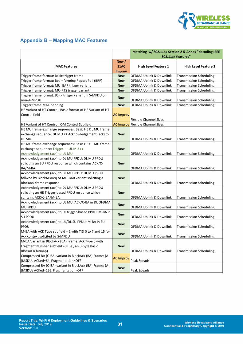
Report Title: Wi-Fi 6 Deployment Guidelines & Scenarios Issue Date: July 2019 Version: 1.0
31 Wireless Broadband Alliance Confidential & Proprietary Copyright © 2019
Appendix B – Mapping MAC Features
MAC FeaturesNew / 11AC
Improv High Level Feature 1 High Level Feature 2
Trigger frame format: Basic trigger frame New OFDMA Uplink & Downlink Transmission SchedulingTrigger frame format: Beamforming Report Poll (BRP) New OFDMA Uplink & Downlink Transmission SchedulingTrigger frame format: MU_BAR trigger variant New OFDMA Uplink & Downlink Transmission SchedulingTrigger frame format: MU-RTS trigger variant New OFDMA Uplink & Downlink Transmission SchedulingTrigger frame format: BSRP trigger variant in S-MPDU or non-A-MPDU
NewOFDMA Uplink & Downlink Transmission Scheduling
Trigger frame MAC padding New OFDMA Uplink & Downlink Transmission SchedulingHE Variant of HT Control: Basic format of HE Variant of HT Control field AC Improv
Flexible Channel SizesHE Variant of HT Control: OM Control Subfield AC Improv Flexible Channel SizesHE MU frame exchange sequences: Basic HE DL MU frame exchange sequence: DL MU ++ Acknowledgement (ack) to DL MU
NewOFDMA Uplink & Downlink Transmission Scheduling
HE MU frame exchange sequences: Basic HE UL MU frame exchange sequence: Trigger ++ UL MU ++ Acknowledgement (ack) to UL MU
NewOFDMA Uplink & Downlink Transmission Scheduling
Acknowledgement (ack) to DL MU PPDU: DL MU PPDU soliciting an SU PPDU response which contains ACK/C-BA/M-BA
NewOFDMA Uplink & Downlink Transmission Scheduling
Acknowledgement (ack) to DL MU PPDU: DL MU PPDU follwed by BlockAckReq or MU-BAR variant soliciting a BlockAck frame response
NewOFDMA Uplink & Downlink Transmission Scheduling
Acknowledgement (ack) to DL MU PPDU: DL MU PPDU soliciting an HE Trigger-based PPDU response which contains ACK/C-BA/M-BA
NewOFDMA Uplink & Downlink Transmission Scheduling
Acknowledgement (ack) to UL MU: ACK/C-BA in DL OFDMA MU PPDU
NewOFDMA Uplink & Downlink Transmission Scheduling
Acknowledgement (ack) to UL trigger-based PPDU: M-BA in SU PPDU
NewOFDMA Uplink & Downlink Transmission Scheduling
Acknowledgement (ack) to UL/DL SU PPDU: M-BA in SU PPDU
NewOFDMA Uplink & Downlink Transmission Scheduling
M-BA with ACK Type subfield = 1 with TID 0 to 7 and 15 for Ack context solicited by S-MPDU
NewOFDMA Uplink & Downlink Transmission Scheduling
M-BA Variant in BlockAck (BA) Frame: Ack Type 0 with Fragment Number subfield =0 (i.e., an 8-byte basic BlockACK bitmap)
NewOFDMA Uplink & Downlink Transmission Scheduling
Compressed BA (C-BA) variant in BlockAck (BA) Frame: (A-)MSDUs ACKed=64, Fragmentation=OFF
AC ImprovPeak Speads
Compressed BA (C-BA) variant in BlockAck (BA) Frame: (A-)MSDUs ACKed=256, Fragmentation=OFF
NewPeak Speads
Matching w/ 802.11ax Section 2 & Annex "decoding IEEE 802.11ax features"
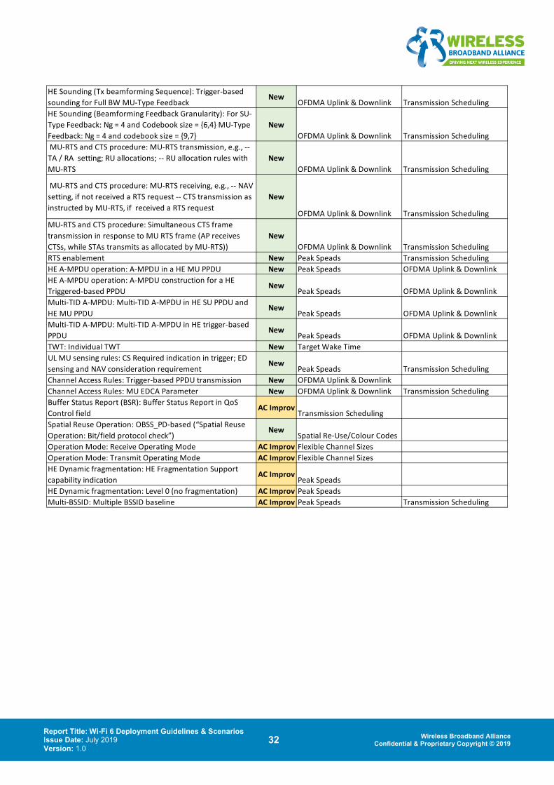
Report Title: Wi-Fi 6 Deployment Guidelines & Scenarios Issue Date: July 2019 Version: 1.0
32 Wireless Broadband Alliance Confidential & Proprietary Copyright © 2019
HE Sounding (Tx beamforming Sequence): Trigger-based sounding for Full BW MU-Type Feedback
NewOFDMA Uplink & Downlink Transmission Scheduling
HE Sounding (Beamforming Feedback Granularity): For SU-Type Feedback: Ng = 4 and Codebook size = {6,4} MU-Type Feedback: Ng = 4 and codebook size = {9,7}
NewOFDMA Uplink & Downlink Transmission Scheduling
MU-RTS and CTS procedure: MU-RTS transmission, e.g., -- TA / RA setting; RU allocations; -- RU allocation rules with MU-RTS
NewOFDMA Uplink & Downlink Transmission Scheduling
MU-RTS and CTS procedure: MU-RTS receiving, e.g., -- NAV setting, if not received a RTS request -- CTS transmission as instructed by MU-RTS, if received a RTS request
New
OFDMA Uplink & Downlink Transmission SchedulingMU-RTS and CTS procedure: Simultaneous CTS frame transmission in response to MU RTS frame (AP receives CTSs, while STAs transmits as allocated by MU-RTS))
NewOFDMA Uplink & Downlink Transmission Scheduling
RTS enablement New Peak Speads Transmission SchedulingHE A-MPDU operation: A-MPDU in a HE MU PPDU New Peak Speads OFDMA Uplink & DownlinkHE A-MPDU operation: A-MPDU construction for a HE Triggered-based PPDU
NewPeak Speads OFDMA Uplink & Downlink
Multi-TID A-MPDU: Multi-TID A-MPDU in HE SU PPDU and HE MU PPDU
NewPeak Speads OFDMA Uplink & Downlink
Multi-TID A-MPDU: Multi-TID A-MPDU in HE trigger-based PPDU
NewPeak Speads OFDMA Uplink & Downlink
TWT: Individual TWT New Target Wake TimeUL MU sensing rules: CS Required indication in trigger; ED sensing and NAV consideration requirement
NewPeak Speads Transmission Scheduling
Channel Access Rules: Trigger-based PPDU transmission New OFDMA Uplink & DownlinkChannel Access Rules: MU EDCA Parameter New OFDMA Uplink & Downlink Transmission SchedulingBuffer Status Report (BSR): Buffer Status Report in QoS Control field
AC ImprovTransmission Scheduling
Spatial Reuse Operation: OBSS_PD-based (“Spatial Reuse Operation: Bit/field protocol check”)
NewSpatial Re-Use/Colour Codes
Operation Mode: Receive Operating Mode AC Improv Flexible Channel SizesOperation Mode: Transmit Operating Mode AC Improv Flexible Channel SizesHE Dynamic fragmentation: HE Fragmentation Support capability indication
AC ImprovPeak Speads
HE Dynamic fragmentation: Level 0 (no fragmentation) AC Improv Peak SpeadsMulti-BSSID: Multiple BSSID baseline AC Improv Peak Speads Transmission Scheduling
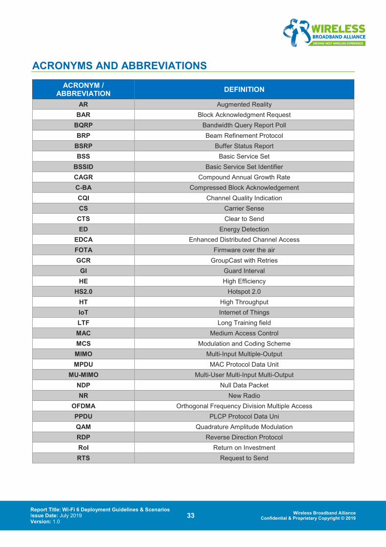
Report Title: Wi-Fi 6 Deployment Guidelines & Scenarios Issue Date: July 2019 Version: 1.0
33 Wireless Broadband Alliance Confidential & Proprietary Copyright © 2019
ACRONYMS AND ABBREVIATIONS ACRONYM /
ABBREVIATION DEFINITION
AR Augmented Reality BAR Block Acknowledgment Request
BQRP Bandwidth Query Report Poll BRP Beam Refinement Protocol
BSRP Buffer Status Report BSS Basic Service Set
BSSID Basic Service Set Identifier CAGR Compound Annual Growth Rate C-BA Compressed Block Acknowledgement CQI Channel Quality Indication CS Carrier Sense
CTS Clear to Send ED Energy Detection
EDCA Enhanced Distributed Channel Access FOTA Firmware over the air GCR GroupCast with Retries
GI Guard Interval HE High Efficiency
HS2.0 Hotspot 2.0 HT High Throughput IoT Internet of Things LTF Long Training field MAC Medium Access Control MCS Modulation and Coding Scheme MIMO Multi-Input Multiple-Output MPDU MAC Protocol Data Unit
MU-MIMO Multi-User Multi-Input Multi-Output NDP Null Data Packet NR New Radio
OFDMA Orthogonal Frequency Division Multiple Access PPDU PLCP Protocol Data Uni QAM Quadrature Amplitude Modulation RDP Reverse Direction Protocol RoI Return on Investment RTS Request to Send
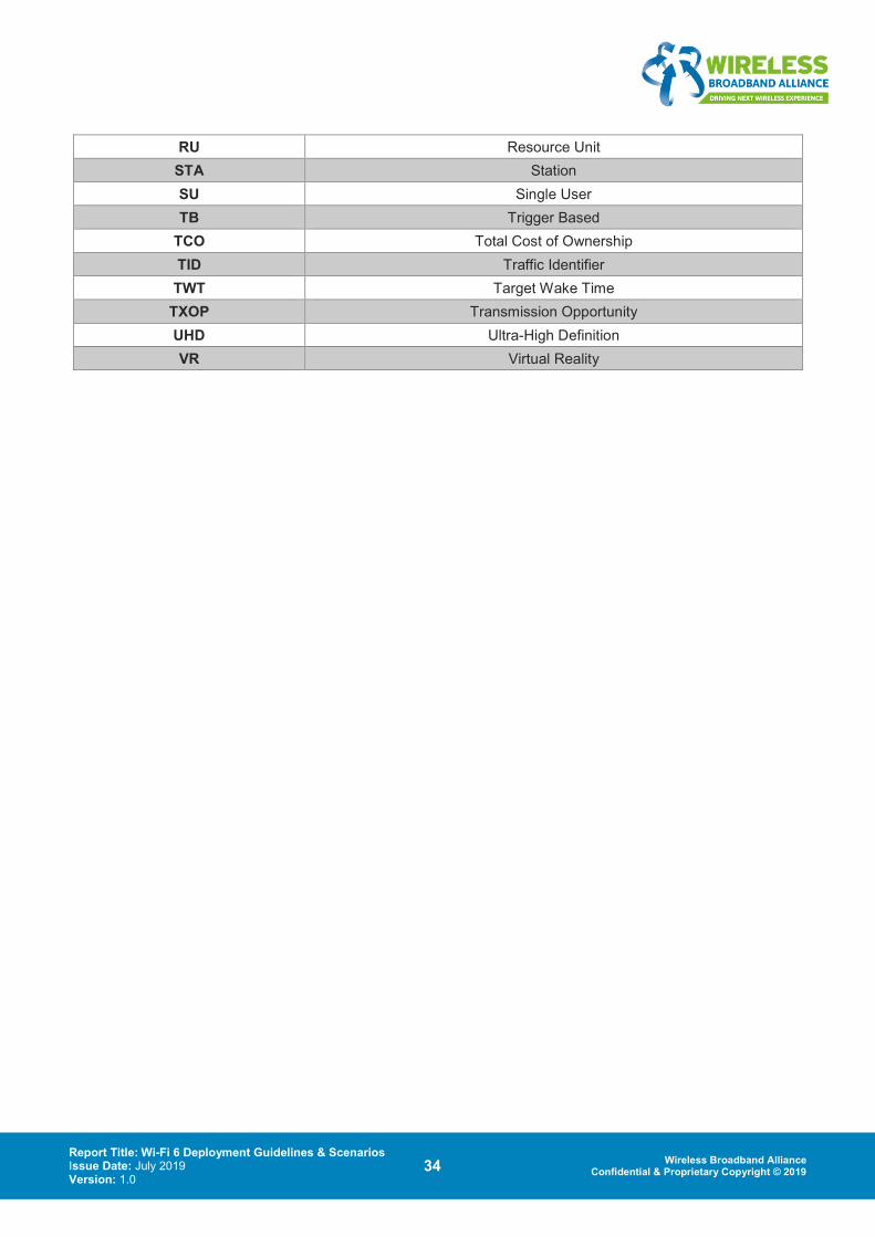
Report Title: Wi-Fi 6 Deployment Guidelines & Scenarios Issue Date: July 2019 Version: 1.0
34 Wireless Broadband Alliance Confidential & Proprietary Copyright © 2019
RU Resource Unit STA Station SU Single User TB Trigger Based
TCO Total Cost of Ownership TID Traffic Identifier TWT Target Wake Time
TXOP Transmission Opportunity UHD Ultra-High Definition VR Virtual Reality

For other publications please visit:
wballiance.com/resources/wba-white-papers
To participate in future projects, please contact: [email protected]
PARTICIPANT LIST & EDITORIAL TEAM
COMPANY NAME ROLE Intel Necati Canpolat Project Leader
Boingo Wireless Kishore Raja Chief Editor & Project Co-Leader Broadcom Florin Baboescu Project Co-Leader
Cisco Mark Grayson Project Co-Leader Accuris Networks Finbarr Coghlan Editorial team member
Aruba / HPE Peter Thornycroft Editorial team member BT Steve Dyett Editorial team member BT Simon Ringland Editorial team member BT Tim Twell Editorial team member
Boingo Wireless Janne Linkola Editorial team member Broadcom Gabriel Desjardins Editorial team member CableLabs Lili Hervieu Editorial team member CableLabs Luther Smith Editorial team member
C-DOT India Kavita Mathur Editorial team member C-DOT India Sandeep Agrawal Editorial team member C-DOT India Suja S Editorial team member
Charter Communications Loay Kreishan Editorial team member Charter Communications Praveen Srivastava Editorial team member
Huawei Edward Au Editorial team member Huawei Lei Wang Editorial team member iBWave Ziad Akl-Chedid Editorial team member
Intel Chitto Gosh Editorial team member Ruckus/Commscope Mark Hamilton Editorial team member
Qualcomm Rolf de Vegt Editorial team member WBA Bruno Tomas Editorial team member