Embed Size (px)
Citation preview

applied sciences
Article
Whole-Body Motion Planning for a Six-Legged RobotWalking on Rugged Terrain
Jie Chen 1,*, Fan Gao 1, Chao Huang 1 and Jie Zhao 2
1 School of Mechanical Engineering and Automation, Northeastern University, Shenyang 110819, China;[email protected] (F.G.); [email protected] (C.H.)
2 State Key Laboratory of Robotics and System, Harbin Institute of Technology, Harbin 150001, China;[email protected]
* Correspondence: [email protected]
Received: 23 October 2019; Accepted: 29 November 2019; Published: 4 December 2019�����������������
Abstract: Whole-body motion planning is a key ability for legged robots, which allows for thegeneration of terrain adaptive behaviors and thereby improved mobility in complex environment.To this end, this paper addresses the issue of terrain geometry based whole-body motion planning fora six-legged robot over a rugged terrain. The whole-body planning is decomposed into two sub-tasks:leg support and swing. For leg support planning, the target pose of the robot torso in a walking stepis first found by maximizing the stability margin at the moment of support-swing transition andmatching the orientation of the support polygon formed by target footholds. Then, the torso andthereby the leg support trajectories are generated using cubic spline interpolation and transferred intojoint space through inverse kinematics. In terms of leg swing planning, the trajectories in a walkingstep are generated by solving an optimal problem that satisfies three constraints and a bioinspiredobjective function. The proposed whole-body motion planning strategies are implemented witha simulation and a real-world six-legged robot, and the results show that stable and collision-freemotions can be produced for the robot over rugged terrains.
Keywords: six-legged robot; whole-body motion planning; rugged terrain; support; swing
1. Introduction
Over the last few decades, six-legged robots seem to have received much attention for severalreasons. First, six-legged robots are useful scientific tools that can be employed to investigatecomplicated biological mechanisms such as biomechanics and neuroscience, on the side of biology,and planning and control algorithms, on the side of robotics [1–5]. Second, six-legged robots canbe used in many application scenarios like search and rescue [6,7]. As a result, to date a variety ofsix-legged robotic platforms have been constructed.
Locomotion in complex terrain is one of the fundamental topics for legged robotic research.Broadly, various strategies adopted in the literature may be categorized into different approaches.The first is an executing-reacting approach which means the robot executes its predefined motionsfirst then adapts to terrain changes through reactive behaviors. An example in this approach is theRHex-like robots which employ special-designed curved legs to achieve robust locomotion in ruggedterrains [8,9]. Such designs are simple, reliable and able to mechanically adapt to a certain degree ofterrain roughness. Further, a number of legged robots integrate various control strategies to activelyadapt to rugged terrain. Impedance control and posture control are two commonly used strategies inthis line [6,10,11]. A number of six-legged robots also integrate different reflexes, including stretchreflex, searching reflex, stepping reflex, and elevator reflex, to react to obstacles or holes during steppingmotions, thereby increasing the robot mobility on unstructured terrain [6,11–13]. An alternate approach
Appl. Sci. 2019, 9, 5284; doi:10.3390/app9245284 www.mdpi.com/journal/applsci

Appl. Sci. 2019, 9, 5284 2 of 11
is a planning–reacting paradigm, which means reasonable motion would be deliberately planned beforerobot executing and additional terrain uncertainty would be overcome by reactive motion control.For example, Lee and Song propose a Bezier curves based path planning method, which enablesa quadruped robot to generate a feasible path in an obstacle-strewn environment [13]. Likewise, in [14],the authors label the obstacles as accessible or inaccessible regions and then plan path for a legged robotby employing the potential field algorithm. A recent example is the BigDog quadruped robot, in whichan optimal path was found using 2D cost map and A ∗ algorithm [15]. On this basis, the plannedpath is commanded to be followed using robustly reactive motion controllers. With these approaches,robotic legged locomotion can be accomplished over moderately rugged terrains.
Similar to human rock-climbing, whereby the climber has to carefully plan his/her foot/handmotions according to the rock wall and his/her capability, over severe rugged terrains, deliberatewhole-body motion planning has to be conducted for legged robots. In addition, careful whole-bodymotion planning is also helpful for legged robots to address the limitations of its own kinematics,for example, a better kinematic margin for subsequent robot movements. In this line, Belter et al.proposes two-layered whole-body motion planning for the six-legged robot Messor according tosurrounding environment models. The authors use a higher-level planner, which uses A ∗ algorithm toplan a path, and a lower-level planner, in which the guided-RRT is applied to find feasible motiontrajectories of 18-dimensional joint space [7]. Kalakrishnan et al. employs a combination method ofplanning and optimization for a quadruped robot walking dynamically over rugged terrains [16,17].The trajectory of the robot CoG is generated by a series of quintic spline curves. The trajectoryof the robot torso is given by optimizing squared accelerations along the trajectory based on thezero-moment point (ZMP) stability criterion. The foot trajectories are initially generated according tothe convex hull of the terrain from the start location and the target location using piece-wise quinticsplines, and then subsequently optimized to eliminate potential shin or knee collisions. Vernaza etal. decompose the planning problem of a quadrupedal robot into two main phases, namely an initialglobal planning phase, which searches for feasible footstep trajectories by the use of the R* searchalgorithm, and an execution phase, which dynamically generates complete joint trajectories accordingto the planned footstep trajectories [18]. All these attempts have demonstrated the effectiveness ofappropriately generating whole-body motions for legged robots and thereby increased the robotmobility on unstructured terrain.
In this paper, we focus on the issue of terrain geometry based whole-body motion planning fora six-legged robot walking on rugged terrain. In our method, leg support and swing are plannedrespectively. For leg support, maximizing the stability margin of support-swing transition is mainlyconsidered, which is distinct from the existing method. In terms of leg swing planning, the problemwas formulated as an optimal control procedure that satisfies a series of locomotion task terms whileminimizing a biologically-based objective function. To better concentrate on the motion planningproblem, it is assumed that the terrain has been already obtained in advance and described by a 2.5Dgrid-type digital elevation model (DEM). DEM provides a compact representation, allows for efficientprocessing, and avoids the complexity of using full three-dimensional maps. The remainder of thepaper is organized as follows: Section 2 presents a whole-body motion planning method for six-leggedrobots, including support and swing planning. Then, the results of both the simulation and experimentare presented and analyzed in Section 3, followed by a necessary interpretation of the observedbehaviors. Finally, Section 4 concludes with a brief summary of the paper.
2. Methods
Whole-body motion planning is crucial to achieve mobile and robust robot walking.For a six-legged robot, the whole-body motion can be divided into two parts: one is that someof the six legs support and propel the torso to achieve corresponding movements on the ground;the other is that the rest legs take the torso as a floating base and perform swing movements in the

Appl. Sci. 2019, 9, 5284 3 of 11
air. This section first analyzes the stability of six-legged robotic walking, then introduces the motionplanning methods of support and swing, respectively.
2.1. Stability Analysis of Six-Legged Robotic Walking
Stability is the premise of effective motion of a robot. It is necessary to ensure sufficient stabilitymargin in the whole process of six-legged robotic walking [19]. That is to say, the center of gravity(CoG) of the robot should be always in the horizontal projection of the supporting polygon formed bysupporting legs at the beginning, during moving and at the end of each waking step. Figure 1 illustratesan example of tripod gait with a duty cycle of 0.5. In this example, a, b, and c are the supportingpoints of current supporting legs, ∆abc is the formed supporting triangle; d, e, and f are the targetsupporting points for the following step of the robot, ∆def is the supporting triangle for the followingstep; the shaded area is the overlap of ∆abc and ∆def; O1, O2, and O3 are the centers of the maximuminner circle of ∆abc, ∆def and the overlap, respectively. Without loss of generality, it is assumed that,at the beginning, the horizontal projection of the robot CoG is at the incenter O1 of ∆abc. When thesix-legged robot starts to move, the projection of the robot CoG on the horizontal plane gradually movesalong the forward direction from O1 until the walking is completed. According to the definition of robotstability [19], in order to ensure the stability of the robot in the whole walking process, two conditionsneed to be satisfied: 1. Before the swing legs contact the ground, the projection of the robot CoG must bewithin ∆abc; 2. After the swing legs contact the ground, the projection of the robot CoG must be within∆def. This requires that the projection of the robot CoG on the horizontal plane falls in the overlapof the two triangles at the moment of support-swing transition. Otherwise, when the supporting legchanges, the robot will become unstable, thereby leading to failure of the whole walking task or evendamage to the robot hardware. Furthermore, in order to ensure that the robot can maintain a largestability margin at the moment of support-swing transition, it is better that the horizontal projection ofthe robot CoG falls at the incenter O2 of the overlap at the moment of transition.
Appl. Sci. 2019, 9, x FOR PEER REVIEW 3 of 11
2.1. Stability Analysis of Six-Legged Robotic Walking
Stability is the premise of effective motion of a robot. It is necessary to ensure sufficient stability
margin in the whole process of six-legged robotic walking [19]. That is to say, the center of gravity
(CoG) of the robot should be always in the horizontal projection of the supporting polygon formed
by supporting legs at the beginning, during moving and at the end of each waking step. Figure 1
illustrates an example of tripod gait with a duty cycle of 0.5. In this example, a, b, and c are the
supporting points of current supporting legs, Δabc is the formed supporting triangle; d, e, and f are
the target supporting points for the following step of the robot, Δdef is the supporting triangle for the
following step; the shaded area is the overlap of Δabc and Δdef; O1, O2, and O3 are the centers of the
maximum inner circle of Δabc, Δdef and the overlap, respectively. Without loss of generality, it is
assumed that, at the beginning, the horizontal projection of the robot CoG is at the incenter O1 of
Δabc. When the six-legged robot starts to move, the projection of the robot CoG on the horizontal
plane gradually moves along the forward direction from O1 until the walking is completed.
According to the definition of robot stability [19], in order to ensure the stability of the robot in the
whole walking process, two conditions need to be satisfied: 1. Before the swing legs contact the
ground, the projection of the robot CoG must be within Δabc; 2. After the swing legs contact the
ground, the projection of the robot CoG must be within Δdef. This requires that the projection of the
robot CoG on the horizontal plane falls in the overlap of the two triangles at the moment of support-
swing transition. Otherwise, when the supporting leg changes, the robot will become unstable,
thereby leading to failure of the whole walking task or even damage to the robot hardware.
Furthermore, in order to ensure that the robot can maintain a large stability margin at the moment of
support-swing transition, it is better that the horizontal projection of the robot CoG falls at the
incenter O2 of the overlap at the moment of transition.
Figure 1. Schematic of stability of six-legged robotic walking with tripod gait.
According to the above analysis, the motion of the robot torso in a walking step can be divided
into two stages: as illustrated in Figure 1, the first stage is the movement from O1 to O2, and the second
stage is from O2 to O3. This paper mainly discusses the planning problem of the first stage, which is
the key point to ensure stable walking. The movement from O2 to O3 is implemented via control
adjustment which is out of the scope of this paper.
2.2. Support Planning
While walking in rugged terrain, the spatial distribution of footholds for support legs is complex
and various, probably leading to inclination and destabilization of the robot. Therefore, it is necessary
to plan, in advance, the movements of the robot torso and thereby the movement of each supporting
leg. In addition, proper motion is also helpful to enhance the stability and terrain adaptability of the
robot. In this context, the six-dimensional torso pose would be considered. The overall process of
support planning is demonstrated in Figure 2.
Figure 1. Schematic of stability of six-legged robotic walking with tripod gait.
According to the above analysis, the motion of the robot torso in a walking step can be dividedinto two stages: as illustrated in Figure 1, the first stage is the movement from O1 to O2, and the secondstage is from O2 to O3. This paper mainly discusses the planning problem of the first stage, which isthe key point to ensure stable walking. The movement from O2 to O3 is implemented via controladjustment which is out of the scope of this paper.
2.2. Support Planning
While walking in rugged terrain, the spatial distribution of footholds for support legs is complexand various, probably leading to inclination and destabilization of the robot. Therefore, it is necessaryto plan, in advance, the movements of the robot torso and thereby the movement of each supporting

Appl. Sci. 2019, 9, 5284 4 of 11
leg. In addition, proper motion is also helpful to enhance the stability and terrain adaptability of therobot. In this context, the six-dimensional torso pose would be considered. The overall process ofsupport planning is demonstrated in Figure 2.Appl. Sci. 2019, 9, x FOR PEER REVIEW 4 of 11
Figure 2. Schematic of the support planning process.
2.2.1. Torso Horizontal Position and Height
For a walking step of the six-legged robot, one key point of motion planning is to find a proper
target state that maximizes the stability margin of the robot, then the robot can move from current
state to the target state. According to geometric knowledge and the definition of stability [19], when
the projection of the robot CoG is exactly at the center of the maximum inner circle of the support
polygon formed by target footholds, the robot can obtain the maximum stability margin. In order to
derive the incenter O2 (Xr, Yr) of the support polygon, as illustrated in Figure 3, the following steps
are adopted:
Figure 3. Flow diagram to find the incenter of the support polygon.
Step 1: Arbitrarily select a point S (Xs, Ys) in the polygon as the incenter to start calculation. In
this paper, we choose the midpoint of two vertices of a polygon that are not adjacent to each other.
Figure 2. Schematic of the support planning process.
2.2.1. Torso Horizontal Position and Height
For a walking step of the six-legged robot, one key point of motion planning is to find a propertarget state that maximizes the stability margin of the robot, then the robot can move from current stateto the target state. According to geometric knowledge and the definition of stability [19], when theprojection of the robot CoG is exactly at the center of the maximum inner circle of the support polygonformed by target footholds, the robot can obtain the maximum stability margin. In order to derive theincenter O2 (Xr, Yr) of the support polygon, as illustrated in Figure 3, the following steps are adopted:
Appl. Sci. 2019, 9, x FOR PEER REVIEW 4 of 11
Figure 2. Schematic of the support planning process.
2.2.1. Torso Horizontal Position and Height
For a walking step of the six-legged robot, one key point of motion planning is to find a proper
target state that maximizes the stability margin of the robot, then the robot can move from current
state to the target state. According to geometric knowledge and the definition of stability [19], when
the projection of the robot CoG is exactly at the center of the maximum inner circle of the support
polygon formed by target footholds, the robot can obtain the maximum stability margin. In order to
derive the incenter O2 (Xr, Yr) of the support polygon, as illustrated in Figure 3, the following steps
are adopted:
Figure 3. Flow diagram to find the incenter of the support polygon.
Step 1: Arbitrarily select a point S (Xs, Ys) in the polygon as the incenter to start calculation. In
this paper, we choose the midpoint of two vertices of a polygon that are not adjacent to each other.
Figure 3. Flow diagram to find the incenter of the support polygon.
Step 1: Arbitrarily select a point S (Xs, Ys) in the polygon as the incenter to start calculation. In thispaper, we choose the midpoint of two vertices of a polygon that are not adjacent to each other.

Appl. Sci. 2019, 9, 5284 5 of 11
Step 2: Calculate the shortest distance from the incenter S to each side of the supporting polygonand the position of the corresponding points. The two points closest to each other were determinedand recorded as A (XA, YA), distance LA, B (XB, YB) and distance LB, respectively.
Step 3: Select a new point C (XC, YC) according to the following rules: if A, B and S are collinear,then C = A; if A, B and S are not collinear, then choose XC = XA + LA
LA+LB(XB −XA)
YC = YA + LALA+LB
(YB −YA)(1)
Step 4: Set the step size factor a, and take a point S’ (Xs, Ys) on the extension line of CS as the newcenter of the calculation circle according to the following rules, namely:
XS′ = XS + a (XS−XC)√(XS−XC)
2+(YS−YC)2
YS′ = YS + a (YS−YC)√(XS−XC)
2+(YS−YC)2
(2)
Step 5: Repeat Step 2 with the newly calculated center S’, and compare the calculated minimumdistance L’ with LA. If the value of L’ increases, continue Steps 3 and 4; otherwise, the step factor isdecreased to 0.5a and recalculate the incenter with Equation (2). With cyclic calculation of the abovesteps, the incenter O2 (Xr, Yr) of the maximum inner circle of the supporting polygon can be obtained.In this regard, the planning task of support legs is to propel the horizontal position of the torso fromthe current O1 to the incenter O2 (Xr, Yr) of the support polygon.
In terms of the torso height, the purpose is to keep a certain distance from the ground. In thispaper, it is prescribed that the robot CoG and the incennter of the supporting polygon are alwaysmaintained at a certain height h. This can prevent the collision between the robot and the groundsimply and effectively.
2.2.2. Torso Posture
The so-called torso posture mainly refers to the inclination of the body in space, which can beexpressed by yaw α, pitch β and roll γ, respectively. Among them, the yaw α is determined by therobot’s moving direction, so the posture planning in this section is mainly the pitch β and roll γ of thetorso. In order to obtain the target posture of the robot torso, the following steps are adopted:
Step 1: Derive the target supporting polygon by fitting the target footholds and calculate the pitchβSP and the roll γSP of the supporting polygon;
Step 2: Calculate the desired pitch βd and roll γd according to the following formula{βd = 0.5(βSP + βa)
γd = 0.5(γSP + γa)(3)
where, βa and γa are the current inclination parameters of the robot torso collected by the pose sensor.So far, we have obtained the initial and termination values of the six-dimensional motion of the
robot torso. Since the torso is passive and has no active driving ability, its movement is completelypropelled by supporting legs. Therefore, the torso motion needs to be transferred to the joint space ofeach supporting leg of the robot. For this purpose, N path points are collected from all directions ofthe torso, and then the path points of each supporting leg joint are obtained by means of kinematictransformation and calculation. Next, these path points are interpolated by cubic spline curve to obtainsmooth joint trajectories. Let θl j
1 ,θl j2 , · · ·θl j
N be the corresponding path points of each supporting legjoint, where l is the number of supporting legs, j = 1, 2 and 3 are the three joints of a certain supportingleg, and N is the number of path points. For any joint j of a supporting leg l, the cubic spline curve S isconstructed to meet the path points and continuity conditions, namely:
Appl. Sci. 2019, 9, 5284 6 of 11
S(ti) = θl ji , i = 1, 2, · · ·N
limt→ti
S(t) = S(ti), i = 2, 3, · · ·N − 1
limt→ti
S′(t) = S′(ti), i = 2, 3, · · ·N − 1
limt→ti
S′′ (t) = S′′ (ti), i = 2, 3, · · ·N − 1
(4)
where ti is the motion time variable corresponding to each path point. In addition, in order to solve theequation, the boundary conditions are further set up:{
S′(t1) = 0S′(tN) = 0
(5)
With a total of 4(N− 1) boundary conditions, the unique joint interpolation trajectories can be obtained.
2.3. Swing Planning
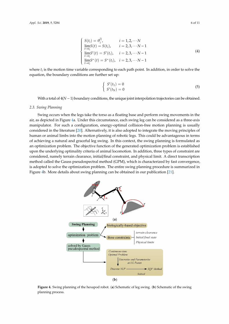
Swing occurs when the legs take the torso as a floating base and perform swing movements in theair, as depicted in Figure 4a. Under this circumstance, each swing leg can be considered as a three-axismanipulator. For such a configuration, energy-optimal collision-free motion planning is usuallyconsidered in the literature [20]. Alternatively, it is also adopted to integrate the moving principles ofhuman or animal limbs into the motion planning of robotic legs. This could be advantageous in termsof achieving a natural and graceful leg swing. In this context, the swing planning is formulated asan optimization problem. The objective function of the generated optimization problem is establishedupon the underlying optimality criteria of animal locomotion. In addition, three types of constraint areconsidered, namely terrain clearance, initial/final constraint, and physical limit. A direct transcriptionmethod called the Gauss pseudospectral method (GPM), which is characterized by fast convergence,is adopted to solve the optimization problem. The entire swing planning procedure is summarized inFigure 4b. More details about swing planning can be obtained in our publication [21].
Appl. Sci. 2019, 9, x FOR PEER REVIEW 6 of 11
' '
'' ''
( ) , 1,2,
lim ( ) ( ), 2,3, 1
lim ( ) ( ), 2,3, 1
lim ( ) ( ), 2,3, 1
i
i
i
lj
i i
it t
it t
it t
S t i N
S t S t i N
S t S t i N
S t S t i N
(4)
where ti is the motion time variable corresponding to each path point. In addition, in order to solve
the equation, the boundary conditions are further set up:
'
1
'
( ) 0
( ) 0N
S t
S t
(5)
With a total of 4(N − 1) boundary conditions, the unique joint interpolation trajectories can be
obtained.
2.3. Swing Planning
Swing occurs when the legs take the torso as a floating base and perform swing movements in
the air, as depicted in Figure 4a. Under this circumstance, each swing leg can be considered as a three-
axis manipulator. For such a configuration, energy-optimal collision-free motion planning is usually
considered in the literature [20]. Alternatively, it is also adopted to integrate the moving principles
of human or animal limbs into the motion planning of robotic legs. This could be advantageous in
terms of achieving a natural and graceful leg swing. In this context, the swing planning is formulated
as an optimization problem. The objective function of the generated optimization problem is
established upon the underlying optimality criteria of animal locomotion. In addition, three types of
constraint are considered, namely terrain clearance, initial/final constraint, and physical limit. A
direct transcription method called the Gauss pseudospectral method (GPM), which is characterized
by fast convergence, is adopted to solve the optimization problem. The entire swing planning
procedure is summarized in Figure 4b. More details about swing planning can be obtained in our
publication [21].
(a)
(b)
Figure 4. Swing planning of the hexapod robot. (a) Schematic of leg swing. (b) Schematic of the swingplanning process.
Appl. Sci. 2019, 9, 5284 7 of 11
3. Results
3.1. Simulation
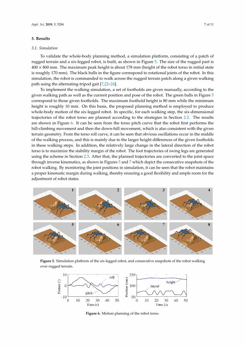
To validate the whole-body planning method, a simulation platform, consisting of a patch ofrugged terrain and a six-legged robot, is built, as shown in Figure 5. The size of the rugged part is400 × 800 mm. The maximum peak height is about 178 mm (height of the robot torso in initial stateis roughly 170 mm). The black balls in the figure correspond to rotational joints of the robot. In thissimulation, the robot is commanded to walk across the rugged terrain patch along a given walkingpath using the alternating-tripod gait [7,22–24].
To implement the walking simulation, a set of footholds are given manually, according to thegiven walking path as well as the current position and pose of the robot. The green balls in Figure 5correspond to those given footholds. The maximum foothold height is 80 mm while the minimumheight is roughly 10 mm. On this basis, the proposed planning method is employed to producewhole-body motion of the six-legged robot. In specific, for each walking step, the six-dimensionaltrajectories of the robot torso are planned according to the strategies in Section 2.2. The resultsare shown in Figure 6. It can be seen from the torso pitch curve that the robot first performs thehill-climbing movement and then the down-hill movement, which is also consistent with the giventerrain geometry. From the torso roll curve, it can be seen that obvious oscillations occur in the middleof the walking process, and this is mainly due to the larger height differences of the given footholdsin these walking steps. In addition, the relatively large change in the lateral direction of the robottorso is to maximize the stability margin of the robot. The foot trajectories of swing legs are generatedusing the scheme in Section 2.3. After that, the planned trajectories are converted to the joint spacethrough inverse kinematics, as shown in Figures 5 and 7 which depict the consecutive snapshots of therobot walking. By monitoring the joint positions in simulation, it can be seen that the robot maintainsa proper kinematic margin during walking, thereby ensuring a good flexibility and ample room for theadjustment of robot states.
Appl. Sci. 2019, 9, x FOR PEER REVIEW 7 of 11
Figure 4. Swing planning of the hexapod robot. (a) Schematic of leg swing. (b) Schematic of the swing
planning process.
3. Results
3.1. Simulation
To validate the whole-body planning method, a simulation platform, consisting of a patch of
rugged terrain and a six-legged robot, is built, as shown in Figure 5. The size of the rugged part is 400
× 800 mm. The maximum peak height is about 178 mm (height of the robot torso in initial state is
roughly 170 mm). The black balls in the figure correspond to rotational joints of the robot. In this
simulation, the robot is commanded to walk across the rugged terrain patch along a given walking
path using the alternating-tripod gait [7,22–24].
To implement the walking simulation, a set of footholds are given manually, according to the
given walking path as well as the current position and pose of the robot. The green balls in Figure 5
correspond to those given footholds. The maximum foothold height is 80 mm while the minimum
height is roughly 10 mm. On this basis, the proposed planning method is employed to produce
whole-body motion of the six-legged robot. In specific, for each walking step, the six-dimensional
trajectories of the robot torso are planned according to the strategies in Section 2.2. The results are
shown in Figure 6. It can be seen from the torso pitch curve that the robot first performs the hill-
climbing movement and then the down-hill movement, which is also consistent with the given terrain
geometry. From the torso roll curve, it can be seen that obvious oscillations occur in the middle of the
walking process, and this is mainly due to the larger height differences of the given footholds in these
walking steps. In addition, the relatively large change in the lateral direction of the robot torso is to
maximize the stability margin of the robot. The foot trajectories of swing legs are generated using the
scheme in Section 2.3. After that, the planned trajectories are converted to the joint space through
inverse kinematics, as shown in Figures 5 and 7 which depict the consecutive snapshots of the robot
walking. By monitoring the joint positions in simulation, it can be seen that the robot maintains a
proper kinematic margin during walking, thereby ensuring a good flexibility and ample room for the
adjustment of robot states.
Figure 5. Simulation platform of the six-legged robot, and consecutive snapshots of the robot walking
over rugged terrain.
Figure 6. Motion planning of the robot torso.
Figure 5. Simulation platform of the six-legged robot, and consecutive snapshots of the robot walkingover rugged terrain.
Appl. Sci. 2019, 9, x FOR PEER REVIEW 7 of 11
Figure 4. Swing planning of the hexapod robot. (a) Schematic of leg swing. (b) Schematic of the swing
planning process.
3. Results
3.1. Simulation
To validate the whole-body planning method, a simulation platform, consisting of a patch of
rugged terrain and a six-legged robot, is built, as shown in Figure 5. The size of the rugged part is 400
× 800 mm. The maximum peak height is about 178 mm (height of the robot torso in initial state is
roughly 170 mm). The black balls in the figure correspond to rotational joints of the robot. In this
simulation, the robot is commanded to walk across the rugged terrain patch along a given walking
path using the alternating-tripod gait [7,22–24].
To implement the walking simulation, a set of footholds are given manually, according to the
given walking path as well as the current position and pose of the robot. The green balls in Figure 5
correspond to those given footholds. The maximum foothold height is 80 mm while the minimum
height is roughly 10 mm. On this basis, the proposed planning method is employed to produce
whole-body motion of the six-legged robot. In specific, for each walking step, the six-dimensional
trajectories of the robot torso are planned according to the strategies in Section 2.2. The results are
shown in Figure 6. It can be seen from the torso pitch curve that the robot first performs the hill-
climbing movement and then the down-hill movement, which is also consistent with the given terrain
geometry. From the torso roll curve, it can be seen that obvious oscillations occur in the middle of the
walking process, and this is mainly due to the larger height differences of the given footholds in these
walking steps. In addition, the relatively large change in the lateral direction of the robot torso is to
maximize the stability margin of the robot. The foot trajectories of swing legs are generated using the
scheme in Section 2.3. After that, the planned trajectories are converted to the joint space through
inverse kinematics, as shown in Figures 5 and 7 which depict the consecutive snapshots of the robot
walking. By monitoring the joint positions in simulation, it can be seen that the robot maintains a
proper kinematic margin during walking, thereby ensuring a good flexibility and ample room for the
adjustment of robot states.
Figure 5. Simulation platform of the six-legged robot, and consecutive snapshots of the robot walking
over rugged terrain.
Figure 6. Motion planning of the robot torso. Figure 6. Motion planning of the robot torso.

Appl. Sci. 2019, 9, 5284 8 of 11
Appl. Sci. 2019, 9, x FOR PEER REVIEW 8 of 11
(a) leg 1 (b) leg 2
(c) leg 3 (d) leg 4
(e) leg 5 (f) leg 6
Figure 7. Trajectories of all the joints of the robot.
3.2. Experimental Study
This section discusses the experimental verification of the proposed planning method with our
six-legged robotic platform (as illustrated in Figure 8). Specific design and control details about the
robot are available in references [5,21,25]. The experimental setup is illustrated in Figure 9. The robot
is commanded to walk through the specified terrain with a certain initial state. The terrain, which is
3D printed by PLA material, is irregular wave shape. Its size is about 850 × 800 mm (width × length).
The maximum peak height is about 160 mm. According to our experimental observations, for the
terrain with small obstacles shown in Figure 8, the irregularities can be overcome using fixed motions
and reactive control. However, the robot would capsize if the fixed motions are still used for the
irregular wave terrain in Figure 9. This is because, severe nonuniform distribution of foot forces and
foot slippages would occur when the robot places its feet onto the irregular peaks. As a result, it is
necessary to plan the whole-body motion of the robot according to the terrain in advance.
Figure 8. Physical prototype of the robot.
Figure 9. Schematic of walking experiment on irregular wave terrain.
Figure 7. Trajectories of all the joints of the robot.
3.2. Experimental Study
This section discusses the experimental verification of the proposed planning method with oursix-legged robotic platform (as illustrated in Figure 8). Specific design and control details about therobot are available in references [5,21,25]. The experimental setup is illustrated in Figure 9. The robotis commanded to walk through the specified terrain with a certain initial state. The terrain, which is3D printed by PLA material, is irregular wave shape. Its size is about 850 × 800 mm (width × length).The maximum peak height is about 160 mm. According to our experimental observations, for theterrain with small obstacles shown in Figure 8, the irregularities can be overcome using fixed motionsand reactive control. However, the robot would capsize if the fixed motions are still used for theirregular wave terrain in Figure 9. This is because, severe nonuniform distribution of foot forces andfoot slippages would occur when the robot places its feet onto the irregular peaks. As a result, it isnecessary to plan the whole-body motion of the robot according to the terrain in advance.
Appl. Sci. 2019, 9, x FOR PEER REVIEW 8 of 11
(a) leg 1 (b) leg 2
(c) leg 3 (d) leg 4
(e) leg 5 (f) leg 6
Figure 7. Trajectories of all the joints of the robot.
3.2. Experimental Study
This section discusses the experimental verification of the proposed planning method with our
six-legged robotic platform (as illustrated in Figure 8). Specific design and control details about the
robot are available in references [5,21,25]. The experimental setup is illustrated in Figure 9. The robot
is commanded to walk through the specified terrain with a certain initial state. The terrain, which is
3D printed by PLA material, is irregular wave shape. Its size is about 850 × 800 mm (width × length).
The maximum peak height is about 160 mm. According to our experimental observations, for the
terrain with small obstacles shown in Figure 8, the irregularities can be overcome using fixed motions
and reactive control. However, the robot would capsize if the fixed motions are still used for the
irregular wave terrain in Figure 9. This is because, severe nonuniform distribution of foot forces and
foot slippages would occur when the robot places its feet onto the irregular peaks. As a result, it is
necessary to plan the whole-body motion of the robot according to the terrain in advance.
Figure 8. Physical prototype of the robot.
Figure 9. Schematic of walking experiment on irregular wave terrain.
Figure 8. Physical prototype of the robot.

Appl. Sci. 2019, 9, 5284 9 of 11
Appl. Sci. 2019, 9, x FOR PEER REVIEW 8 of 11
(a) leg 1 (b) leg 2
(c) leg 3 (d) leg 4
(e) leg 5 (f) leg 6
Figure 7. Trajectories of all the joints of the robot.
3.2. Experimental Study
This section discusses the experimental verification of the proposed planning method with our
six-legged robotic platform (as illustrated in Figure 8). Specific design and control details about the
robot are available in references [5,21,25]. The experimental setup is illustrated in Figure 9. The robot
is commanded to walk through the specified terrain with a certain initial state. The terrain, which is
3D printed by PLA material, is irregular wave shape. Its size is about 850 × 800 mm (width × length).
The maximum peak height is about 160 mm. According to our experimental observations, for the
terrain with small obstacles shown in Figure 8, the irregularities can be overcome using fixed motions
and reactive control. However, the robot would capsize if the fixed motions are still used for the
irregular wave terrain in Figure 9. This is because, severe nonuniform distribution of foot forces and
foot slippages would occur when the robot places its feet onto the irregular peaks. As a result, it is
necessary to plan the whole-body motion of the robot according to the terrain in advance.
Figure 8. Physical prototype of the robot.
Figure 9. Schematic of walking experiment on irregular wave terrain. Figure 9. Schematic of walking experiment on irregular wave terrain.
In the experimental procedure, both the robot and the 3D-printed terrain are placed at thedesignated locations, and as a result, the terrain information is known for the robot. In addition,a set of footholds are given manually according to the terrain geometry. The maximum footholdheight is roughly 19 mm while the minimum height is about 148 mm. Under this circumstance,the proposed planning method is used to produce and calculate the movements of the torso and legs.Then the joint trajectories are obtained by inverse kinematics. In addition, motion control is crucialfor the experiment implementation. Various robot control methods have been proposed, effectivelyimproving the performance of robots [26–28]. In this experiment, our aim is to validate the proposedmotion planning method, as a result, each joint is just PD controlled to ensure accurate leg movements,and impedance control is added in each leg-end to deal with ground reaction force. Snapshots of thereal-world robot walking over irregular wave terrain are shown in Figure 10. Experiments show thatthe robot successfully traverses the given terrain.
Appl. Sci. 2019, 9, x FOR PEER REVIEW 9 of 11
In the experimental procedure, both the robot and the 3D-printed terrain are placed at the
designated locations, and as a result, the terrain information is known for the robot. In addition, a set
of footholds are given manually according to the terrain geometry. The maximum foothold height is
roughly 19 mm while the minimum height is about 148 mm. Under this circumstance, the proposed
planning method is used to produce and calculate the movements of the torso and legs. Then the joint
trajectories are obtained by inverse kinematics. In addition, motion control is crucial for the
experiment implementation. Various robot control methods have been proposed, effectively
improving the performance of robots [26–28]. In this experiment, our aim is to validate the proposed
motion planning method, as a result, each joint is just PD controlled to ensure accurate leg
movements, and impedance control is added in each leg-end to deal with ground reaction force.
Snapshots of the real-world robot walking over irregular wave terrain are shown in Figure 10.
Experiments show that the robot successfully traverses the given terrain.
Figure 10. Consecutive snapshots of the walking experiment on irregular wave terrain.
Figure 11 shows the trajectory curves of the torso and leg joints during the experiment. The
walking details can be learnt from the trend of these curves. Specifically, as shown in Figure 11a, the
pitch angle of the robot torso first presents an increasing trend, which corresponds to the initial
climbing motion of the robot. Then, the pitch angle shows a decreasing trend, but still maintains
positive value, indicating that the front leg or middle leg of the robot has reached the flat terrain
shown in Figure 9. The pitch angle becomes roughly 0, indicating that the robot has completely
crossed the wave terrain. Small changes of the torso rolling reflect the adjusting effect of the robot
during walking.
(a) (b)
Figure 11. Movement measurements during the walking on irregular wave terrain. (a) the torso pose.
(b) joint trajectories of the left foreleg.
Figure 11b shows variations of the joint angles in the left foreleg of the robot. Overall, the three
joints display a periodic characteristic, which is consistent with the reciprocating motion of legged
locomotion. In addition, the trajectories are also different in each walking cycle, which is, on the one
Figure 10. Consecutive snapshots of the walking experiment on irregular wave terrain.
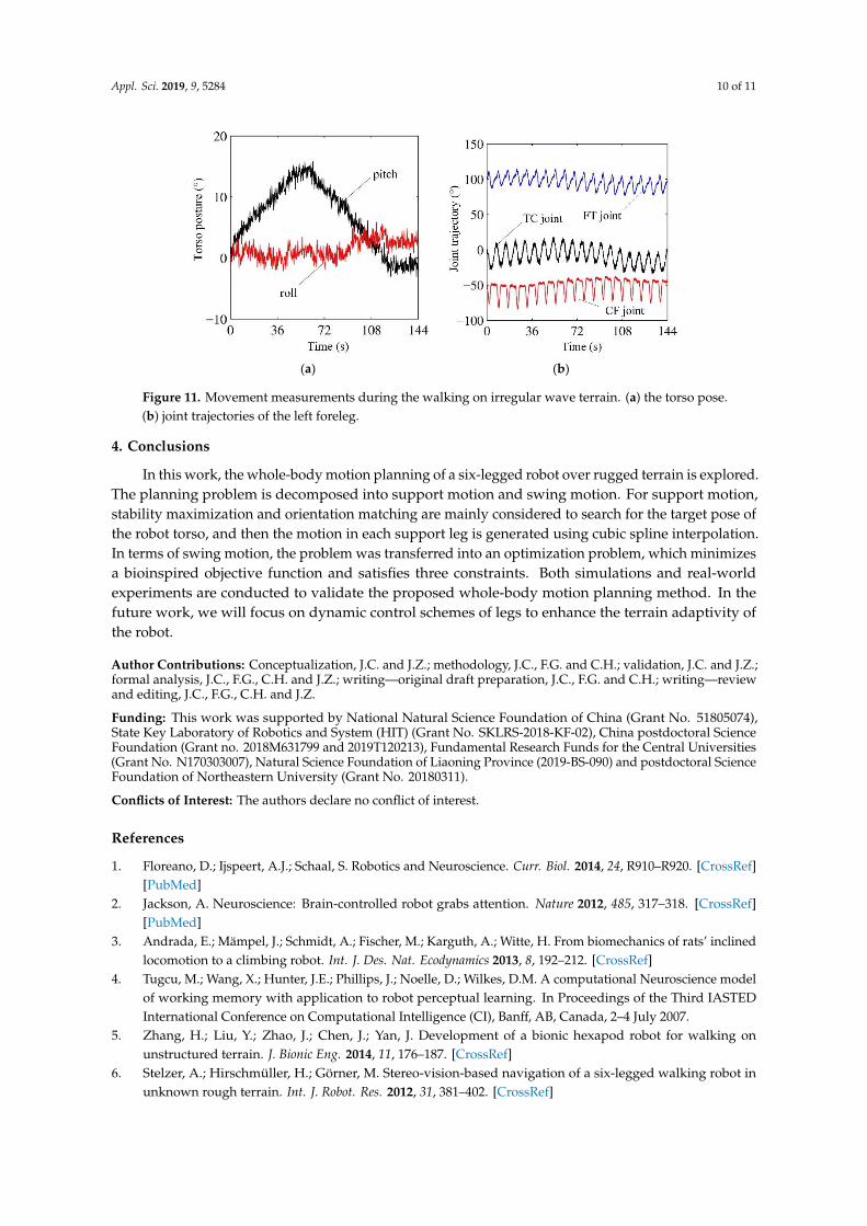
Figure 11 shows the trajectory curves of the torso and leg joints during the experiment. The walkingdetails can be learnt from the trend of these curves. Specifically, as shown in Figure 11a, the pitchangle of the robot torso first presents an increasing trend, which corresponds to the initial climbingmotion of the robot. Then, the pitch angle shows a decreasing trend, but still maintains positive value,indicating that the front leg or middle leg of the robot has reached the flat terrain shown in Figure 9.The pitch angle becomes roughly 0, indicating that the robot has completely crossed the wave terrain.Small changes of the torso rolling reflect the adjusting effect of the robot during walking.
Figure 11b shows variations of the joint angles in the left foreleg of the robot. Overall, the threejoints display a periodic characteristic, which is consistent with the reciprocating motion of leggedlocomotion. In addition, the trajectories are also different in each walking cycle, which is, on theone hand, due to the terrain irregularity and thereby the different step lengths of each step. On theother hand, the adjustments of the control system to each joint are also different in the course ofmotion. Through the walking experiment on irregular wave terrain, the adaptability of the robot oncomplex terrain is further demonstrated, and the effectiveness of the motion planning mentionedabove is illustrated.
Appl. Sci. 2019, 9, 5284 10 of 11
Appl. Sci. 2019, 9, x FOR PEER REVIEW 9 of 11
In the experimental procedure, both the robot and the 3D-printed terrain are placed at the
designated locations, and as a result, the terrain information is known for the robot. In addition, a set
of footholds are given manually according to the terrain geometry. The maximum foothold height is
roughly 19 mm while the minimum height is about 148 mm. Under this circumstance, the proposed
planning method is used to produce and calculate the movements of the torso and legs. Then the joint
trajectories are obtained by inverse kinematics. In addition, motion control is crucial for the
experiment implementation. Various robot control methods have been proposed, effectively
improving the performance of robots [26–28]. In this experiment, our aim is to validate the proposed
motion planning method, as a result, each joint is just PD controlled to ensure accurate leg
movements, and impedance control is added in each leg-end to deal with ground reaction force.
Snapshots of the real-world robot walking over irregular wave terrain are shown in Figure 10.
Experiments show that the robot successfully traverses the given terrain.
Figure 10. Consecutive snapshots of the walking experiment on irregular wave terrain.
Figure 11 shows the trajectory curves of the torso and leg joints during the experiment. The
walking details can be learnt from the trend of these curves. Specifically, as shown in Figure 11a, the
pitch angle of the robot torso first presents an increasing trend, which corresponds to the initial
climbing motion of the robot. Then, the pitch angle shows a decreasing trend, but still maintains
positive value, indicating that the front leg or middle leg of the robot has reached the flat terrain
shown in Figure 9. The pitch angle becomes roughly 0, indicating that the robot has completely
crossed the wave terrain. Small changes of the torso rolling reflect the adjusting effect of the robot
during walking.
(a) (b)
Figure 11. Movement measurements during the walking on irregular wave terrain. (a) the torso pose.
(b) joint trajectories of the left foreleg.
Figure 11b shows variations of the joint angles in the left foreleg of the robot. Overall, the three
joints display a periodic characteristic, which is consistent with the reciprocating motion of legged
locomotion. In addition, the trajectories are also different in each walking cycle, which is, on the one
Figure 11. Movement measurements during the walking on irregular wave terrain. (a) the torso pose.(b) joint trajectories of the left foreleg.
4. Conclusions
In this work, the whole-body motion planning of a six-legged robot over rugged terrain is explored.The planning problem is decomposed into support motion and swing motion. For support motion,stability maximization and orientation matching are mainly considered to search for the target pose ofthe robot torso, and then the motion in each support leg is generated using cubic spline interpolation.In terms of swing motion, the problem was transferred into an optimization problem, which minimizesa bioinspired objective function and satisfies three constraints. Both simulations and real-worldexperiments are conducted to validate the proposed whole-body motion planning method. In thefuture work, we will focus on dynamic control schemes of legs to enhance the terrain adaptivity ofthe robot.
Author Contributions: Conceptualization, J.C. and J.Z.; methodology, J.C., F.G. and C.H.; validation, J.C. and J.Z.;formal analysis, J.C., F.G., C.H. and J.Z.; writing—original draft preparation, J.C., F.G. and C.H.; writing—reviewand editing, J.C., F.G., C.H. and J.Z.
Funding: This work was supported by National Natural Science Foundation of China (Grant No. 51805074),State Key Laboratory of Robotics and System (HIT) (Grant No. SKLRS-2018-KF-02), China postdoctoral ScienceFoundation (Grant no. 2018M631799 and 2019T120213), Fundamental Research Funds for the Central Universities(Grant No. N170303007), Natural Science Foundation of Liaoning Province (2019-BS-090) and postdoctoral ScienceFoundation of Northeastern University (Grant No. 20180311).
Conflicts of Interest: The authors declare no conflict of interest.
References
1. Floreano, D.; Ijspeert, A.J.; Schaal, S. Robotics and Neuroscience. Curr. Biol. 2014, 24, R910–R920. [CrossRef][PubMed]
2. Jackson, A. Neuroscience: Brain-controlled robot grabs attention. Nature 2012, 485, 317–318. [CrossRef][PubMed]
3. Andrada, E.; Mämpel, J.; Schmidt, A.; Fischer, M.; Karguth, A.; Witte, H. From biomechanics of rats’ inclinedlocomotion to a climbing robot. Int. J. Des. Nat. Ecodynamics 2013, 8, 192–212. [CrossRef]
4. Tugcu, M.; Wang, X.; Hunter, J.E.; Phillips, J.; Noelle, D.; Wilkes, D.M. A computational Neuroscience modelof working memory with application to robot perceptual learning. In Proceedings of the Third IASTEDInternational Conference on Computational Intelligence (CI), Banff, AB, Canada, 2–4 July 2007.
5. Zhang, H.; Liu, Y.; Zhao, J.; Chen, J.; Yan, J. Development of a bionic hexapod robot for walking onunstructured terrain. J. Bionic Eng. 2014, 11, 176–187. [CrossRef]
6. Stelzer, A.; Hirschmüller, H.; Görner, M. Stereo-vision-based navigation of a six-legged walking robot inunknown rough terrain. Int. J. Robot. Res. 2012, 31, 381–402. [CrossRef]

Appl. Sci. 2019, 9, 5284 11 of 11
7. Belter, D.; Łabecki, P.; Skrzypczynski, P. Adaptive Motion Planning for Autonomous Rough Terrain Traversalwith a Walking Robot. J. Field Robot. 2016, 33, 337–370. [CrossRef]
8. Saranli, U.; Buehler, M.; Koditschek, D.E. RHex: A Simple and Highly Mobile Hexapod Robot. Int. J. Robot.Res. 2001, 20, 616–631. [CrossRef]
9. Altendorfer, R.; Moore, N.; Komsuoglu, H.; Buehler, M.; Brown Jr, H.B.; McMordie, D.; Saranli, U.; Full, R.;Koditschek, D.E. RHex: A biologically inspired hexapod runner. Auton. Robots 2001, 11, 207–213. [CrossRef]
10. Görner, M. The DLR Crawler: Evaluation of gaits and control of an actively compliant six-legged walkingrobot. Ind. Robot Int. J. 2009, 36, 344–351. [CrossRef]
11. Bartsch, S.; Birnschein, T.; Römmermann, M.; Hilljegerdes, J.; Kühn, D.; Kirchner, F. Development of thesix-legged walking and climbing robot SpaceClimber. J. Field Robot. 2012, 29, 506–532. [CrossRef]
12. Albiez, J.C.; Luksch, T.; Berns, K.; Dillmann, R. Reactive reflex-based control for a four-legged walkingmachine. Robot. Auton. Syst. 2003, 44, 181–189. [CrossRef]
13. Lee, J.-K.; Song, S.-M. Path planning and gait of walking machine in an obstacle-strewn environment. J.Robot. Syst. 1991, 8, 801–827. [CrossRef]
14. Bai, S.; Low, K.H. Terrain evaluation and its application to path planning for walking machines. Adv. Robot.2001, 15, 729–748. [CrossRef]
15. Wooden, D.; Malchano, M.; Blankespoor, K.; Howardy, A.; Rizzi, A.A.; Raibert, M. Autonomous navigation forBigDog. In Proceedings of the 2010 IEEE International Conference on Robotics and Automation, Anchorage,Alaska, 4–8 May 2010; pp. 4736–4741.
16. Kalakrishnan, M.; Buchli, J.; Pastor, P.; Mistry, M.; Schaal, S. Fast, robust quadruped locomotion overchallenging terrain. In Proceedings of the IEEE International Conference on Robotics and Automation,Anchorage, Alaska, 4–8 May 2010; pp. 2665–2670.
17. Kalakrishnan, M.; Buchli, J.; Pastor, P.; Mistry, M.; Schaal, S. Learning, planning, and control for quadrupedlocomotion over challenging terrain. Int. J. Robot. Res. 2010, 30, 236–258. [CrossRef]
18. Vernaza, P.; Likhachev, M.; Bhattacharya, S.; Chitta, S.; Kushleyev, A.; Lee, D.D. Search-based planning fora legged robot over rough terrain. In Proceedings of the IEEE International Conference on Robotics andAutomation, Kobe, Japan, 12–17 May 2009; pp. 2380–2387.
19. McGhee, R.B.; Frank, A.A. On the stability properties of quadruped creeping gaits. Math. Biosci. 1968, 3,331–351. [CrossRef]
20. Zhao, Y.; Wang, Y.; Zhou, M.; Wu, J. Energy-Optimal Collision-Free Motion Planning for Multiaxis MotionSystems: An Alternating Quadratic Programming Approach. IEEE Trans. Autom. Sci. Eng. 2019, 16, 327–338.[CrossRef]
21. Chen, J.; Liu, Y.; Zhao, J.; Zhang, H.; Jin, H. Biomimetic Design and Optimal Swing of a Hexapod Robot Leg.J. Bionic Eng. 2014, 11, 26–35. [CrossRef]
22. Bjelonic, M.; Kottege, N.; Homberger, T.; Borges, P.; Beckerle, P.; Chli, M. Weaver: Hexapod robot forautonomous navigation on unstructured terrain. J. Field Robot. 2018, 35, 1063–1079. [CrossRef]
23. Sun, Q.; Gao, F.; Chen, X. Towards dynamic alternating tripod trotting of a pony-sized hexapod robot fordisaster rescuing based on multi-modal impedance control. Robotica 2018, 36, 1048–1076. [CrossRef]
24. de Santos, P.G.; Garcia, E.; Ponticelli, R.; Armada, M. Minimizing Energy Consumption in Hexapod Robots.Adv. Robot. 2009, 23, 681–704. [CrossRef]
25. Chen, J.; Liang, Z.; Zhu, Y.; Zhao, J.J.J.o.B.E. Improving Kinematic Flexibility and Walking Performance ofa Six-legged Robot by Rationally Designing Leg Morphology. J. Bionic Eng. 2019, 16, 608–620. [CrossRef]
26. Li, S.; Zhou, M.; Luo, X. Modified Primal-Dual Neural Networks for Motion Control of RedundantManipulators With Dynamic Rejection of Harmonic Noises. IEEE Trans. Neural Netw. Learn. Syst. 2018, 29,4791–4801. [CrossRef] [PubMed]
27. Sun, P.; Yu, Z. Tracking control for a cushion robot based on fuzzy path planning with safe angular velocity.IEEE/CAA J. Autom. Sin. 2017, 4, 610–619. [CrossRef]
28. Nakhaeinia, D.; Payeur, P.; Laganiere, R. A Mode-Switching Motion Control System for Reactive Interactionand Surface Following Using Industrial Robots. IEEE/CAA J. Autom. Sin. 2018, 5, 670–682. [CrossRef]
© 2019 by the authors. Licensee MDPI, Basel, Switzerland. This article is an open accessarticle distributed under the terms and conditions of the Creative Commons Attribution(CC BY) license (http://creativecommons.org/licenses/by/4.0/).