Embed Size (px)
Citation preview

Instruction Manual: Whipple Flare_R14 Last Updated: February 27th, 2018
Page 1 of 20 www.whipplesuperchargers.com
WHIPPLE FLARE FLASH INSTRUCTION MANUAL
2015 AND UP FORD MUSTANG
WHIPPLE SUPERCHARGERS 3292 NORTH WEBER AVE
FRESNO, CA 93722 TEL 559.442.1261 FAX 559.442.4153
www.whipplesuperchargers.com A color PDF of this manual is available, email tech@w hipplesuperchargers.com for a copy
PREMIUM FUEL ONLY (91 OCTANE OR BETTER ALWAYS) RON+MON/ 2

Instruction Manual: Whipple Flare_R14 Last Updated: February 27th, 2018
Page 2 of 20 www.whipplesuperchargers.com
INSTRUCTIONS 1. The Whipple calibration procedure is based off factory calibration files. If you have an aftermarket calibration, put the
calibration back to STOCK. If you are updating your calibration, it is highly recommended to restore the stock calibration before loading the updated calibration. The new calibration will upload whatever is in the PCM, therefore you will lose your stock file.
2. Whipple supplies each kit with a blank USB thumb drive. This is provided to back up the downloaded file. The Whipple calibration file, after being flashed with Flare, saves the stock file to the Flare file as one larger file. This file is then locked to that vehicle and gives you the option to revert back to stock up to 3 times. Therefore, any future changes or Flight Control modifications require this file. You cannot re-download the calibration file. Whipple highly recommends saving the file to your PC as well as the USB thumb drive. Installers should always give the file and thumb drive to the customer as it contains the stock file and ability to modify options in Flight Control.
3. Prior to downloading any calibration, users will have to register at the Micromotive website. Follow the steps in the manual to complete the registration process. This will require a voucher #, which is provided by Whipple Superchargers after you’ve supplied the requested information.
4. Using your internet browser, follow the link provided to download the Whipple Flare software.
Windows and MAC software http://www.micromotive.net/whipple
5. The link takes you directly to the download options. Using a Windows based PC, select the “RUN” option.
6. In some cases, internet security may say the software is harmful. In this case, select “Options”. Select “RUN ANYWAY”.
7. The software installation will begin automatically. A prompt stating that Flare will be installed on your computer will pop up, select “YES” to continue.

Instruction Manual: Whipple Flare_R14 Last Updated: February 27th, 2018
Page 3 of 20 www.whipplesuperchargers.com
8. Select “NEXT” to continue the installation.
9. Read the License Agreement, if you agree with the terms, select “I ACCEPT THE TERMS OF THE LICENSE AGREEMENT” and then select “NEXT”.
10. Select a folder you would like to safe the Flare program. Standard setup is to the C:\Program Files (x86) folder. You may also select MY DOCUMENTS, DESKTOP or others you are familiar with.

Instruction Manual: Whipple Flare_R14 Last Updated: February 27th, 2018
Page 4 of 20 www.whipplesuperchargers.com
11. After the software is installed, the USB driver will need to be installed for the Canelope Vehicle Interface. Select “NEXT”.
12. Device Driver window should pop up for installation of the USB drivers. Select “NEXT”.
13. Read the License Agreement. If you agree, select “I ACCEPT THIS AGREEMENT” and then select “NEXT”.
14. The Device Driver Installation Wizard will install the driver package, select “FINISH”.

Instruction Manual: Whipple Flare_R14 Last Updated: February 27th, 2018
Page 5 of 20 www.whipplesuperchargers.com
15. Once installed, you will be prompted with a few options. It’s good to always “CREATE DESKTOP SHORTCUT” to find the program quickly. The quick launch is typically not needed.
MAC INSTALLALATION MANUAL: MAC OSX 10.7 or higher
16. Double-click the Flare.dmg file to mount the Flare disk image.
17. Double click the Flare_x.xx.mpkg file to install Flare. A welcome screen will appear. Click “Continue”.
18. Read the License Agreement, if you agree with the terms, click “Continue”.
19. Click “Agree” to continue.
Instruction Manual: Whipple Flare_R14 Last Updated: February 27th, 2018
Page 6 of 20 www.whipplesuperchargers.com
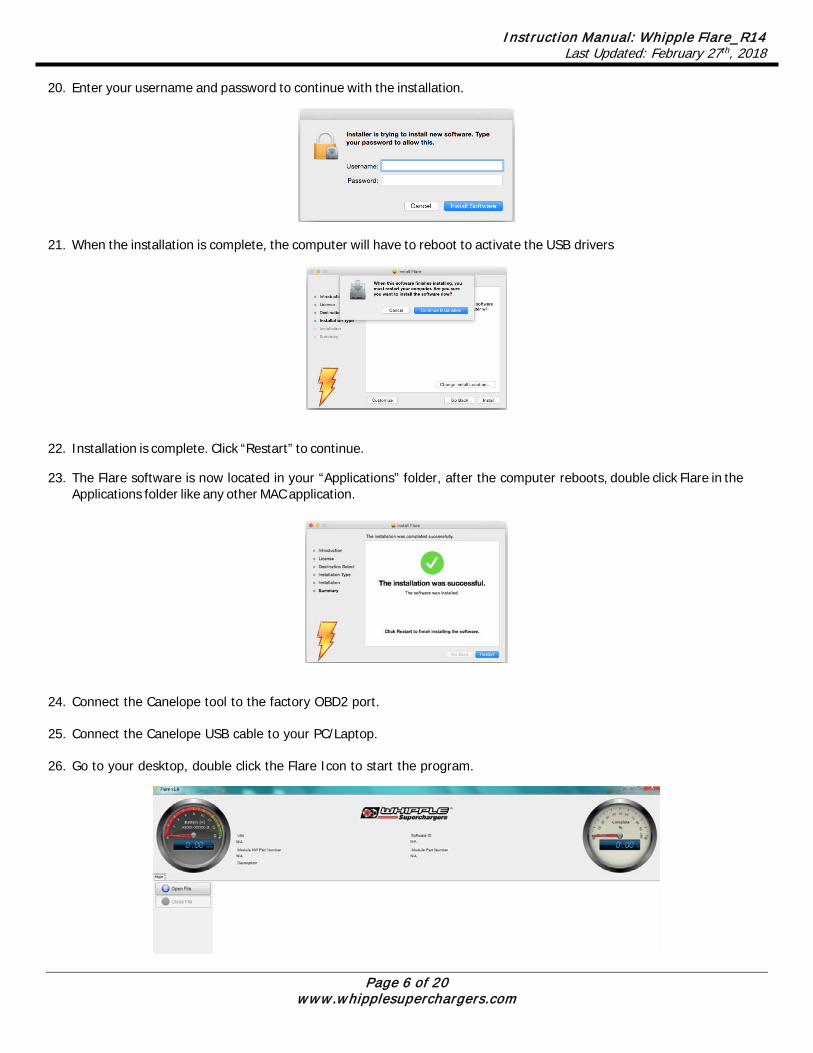
20. Enter your username and password to continue with the installation.
21. When the installation is complete, the computer will have to reboot to activate the USB drivers
22. Installation is complete. Click “Restart” to continue.
23. The Flare software is now located in your “Applications” folder, after the computer reboots, double click Flare in the Applications folder like any other MAC application.
24. Connect the Canelope tool to the factory OBD2 port.
25. Connect the Canelope USB cable to your PC/Laptop.
26. Go to your desktop, double click the Flare Icon to start the program.

Instruction Manual: Whipple Flare_R14 Last Updated: February 27th, 2018
Page 7 of 20 www.whipplesuperchargers.com
27. Turn/push ignition to the key “ON” position. The Flare software will populate the VIN, Module HW Part Number, Software ID, Module Part Number. Note the Software ID number to supply Whipple for your calibration. Once you have this info, turn/push ignition to the “OFF” position.
28. Email [email protected], or fax to 559.442.4153 the following information to receive your VOUCHER NUMBER. Note: Typical response time is up to 24 hours from request time during normal business hours.
VIN NUMBER CANELOPE ID #
TRANS TYPE (AT OR MT)
STOCK STRATEGY ID
THROTTLE BODY (STOCK OR 132MM)
FUEL INJECTOR (58LB OR 72LB) SC #
29. Once you have your voucher number from Whipple Superchargers, use your internet browser, visit the website, www.micromotive.net. Click REGISTER on the upper left corner.

Instruction Manual: Whipple Flare_R14 Last Updated: February 27th, 2018
Page 8 of 20 www.whipplesuperchargers.com
30. Fill out the registration page. For international customers, if the international address does not work, use Whipple Superchargers address. 3292 N. Weber Ave, Fresno, CA 93722 USA.
31. Go to your desktop, double click the Flare icon to start the program. If you have WIFI or an internet connection, click “DOWNLOADER” on the screen and enter the requested information including the VOUCHER NUMBER you requested. Click “DOWNLOAD” to download your calibration file from the server. If you don’t have an internet connection on your laptop, disconnect the tool from the vehicle and take the laptop to an internet source. Connect the Canelope device to the laptop via USB, then “DOWNLOAD”. The file will then download. Internet/WIFI will no longer be needed during the flashing process.
32. Save the calibration file supplied by Whipple in My Documents, Whipple, Calibrations.

Instruction Manual: Whipple Flare_R14 Last Updated: February 27th, 2018
Page 9 of 20 www.whipplesuperchargers.com
33. Turn/push ignition to the key “ON” position. The Flare software will populate the VIN, Module HW Part Number, Software ID, Module Part Number and read the battery voltage. If voltage is below 12.6 volts, do not continue. Connect a battery charger on “LOW” until 12.6 to 14.7 volts is met.
34. Select “OPEN FILE”. Go to “My Documents”, then the “Whipple” folder, then the “Calibrations” folder. Select the .flare file you saved previously.
Instruction Manual: Whipple Flare_R14 Last Updated: February 27th, 2018
Page 10 of 20 www.whipplesuperchargers.com
35. For the Supercharged applications. Select “PROGRAM” tab on the left of the screen. Follow the onscreen menu for flashing the vehicle. Do not let your laptop go into sleep mode. Please note, your stock calibration will be saved in the Flare file for the “Restore” function. Therefore, if you misplace the file and have to download again, you will lose your stock file. Make sure to back up your Flare file after flashing.
36. Once you’re done flashing, cycle the key off for 10 seconds, then back on. Select the Diagnostic tab, read all the DTC (trouble codes). Erase all codes. Note: De-energizing relay code is common after flashing and will go off after a few driving cycles or if you hit clear DTC 5-6 times. The vehicle will run proper even if this code is on.
CAUTION: If Flare aborts programming due to low voltage or if the programming process is interrupted for any reason, you can simply repeat the flash process, however, it will require 2 consecutive flash cycles to complete.
• In some applications, Flare will upload the calibration that is in the PCM prior to programming. The uploaded file will be stored in the same flare file used to program the vehicle. If Flare uploads the original calibration from the vehicle, the “Restore” button will appear so the original calibration can be restored to the vehicle.
37. After flashing the PCM, a crank relearn is required. Failure to may result in a hard time starting and/or sets a random misfire code. To perform a crank relearn, select the “CONFIGURATION” tab. Toggle the “PROFILE LEARNING” to the “ON” position. Follow the on-screen instructions. When changing the flywheel, a crank relearn must be performed. Note that the engine must be at normal operating temp (160deg F+) to perform this test. If you begin the test, but leave it unfinished, it will set a crank learn DTC as it erases the original data. Therefore, to run properly, this procedure will be required.
38. Axle Ratio: • Write down the values displayed for tire and axle for future reference. • Once you’ve recorded the initial values for both, click anywhere on the Axle Ratio gauge on the left-hand side of
the screen and enter the value of the new Axle Ratio.
39. Tire Size: • If your vehicle tire size is different from the value shown on the Tire Size gauge on the right-hand side of the screen, click
anywhere on the Tire Size gauge and enter the value of the new Tire Size.
• For example, if the measured circumference of a tire on one of the vehicle's driven wheels is 84 inches, revolutions per mile for your tire size would be 754.
• Note that circumference should be measured as rolling circumference to account for asymmetry when the tire is loaded with the vehicle’s weight. To do this, mark the bottom edge of the tire and the ground where the marked tire edge sits. Then roll/drive the car forward or backward until the tire mark is against the ground after one revolution. Measure the distance passed on the ground to determine the rolling circumference.
• Another way to calculate revolutions per mile is by utilizing the sizing information written on the side of the tire. For a tire of the size P285/35-19, calculate tire revolutions per mile as follows:
• Revs per mile = 20850 / { [ (2 * 285 * 35) / 2540] + 19 } = 776.4 which rounds down to 776.
WARNING: Do not lose or misplace the flare file if it has uploaded. If the flare file is lost, restoring the original calibration is not possible.
Note: Values less than the minimum value shown on the gauge or exceeding the maximum value on the gauge will not be accepted.
Note: Calculate revolutions per mile by dividing 63360 inches/mile (5280 feet/mile x 12 inches/foot) by the measured circumference of your tire (in inches)
Instruction Manual: Whipple Flare_R14 Last Updated: February 27th, 2018
Page 11 of 20 www.whipplesuperchargers.com
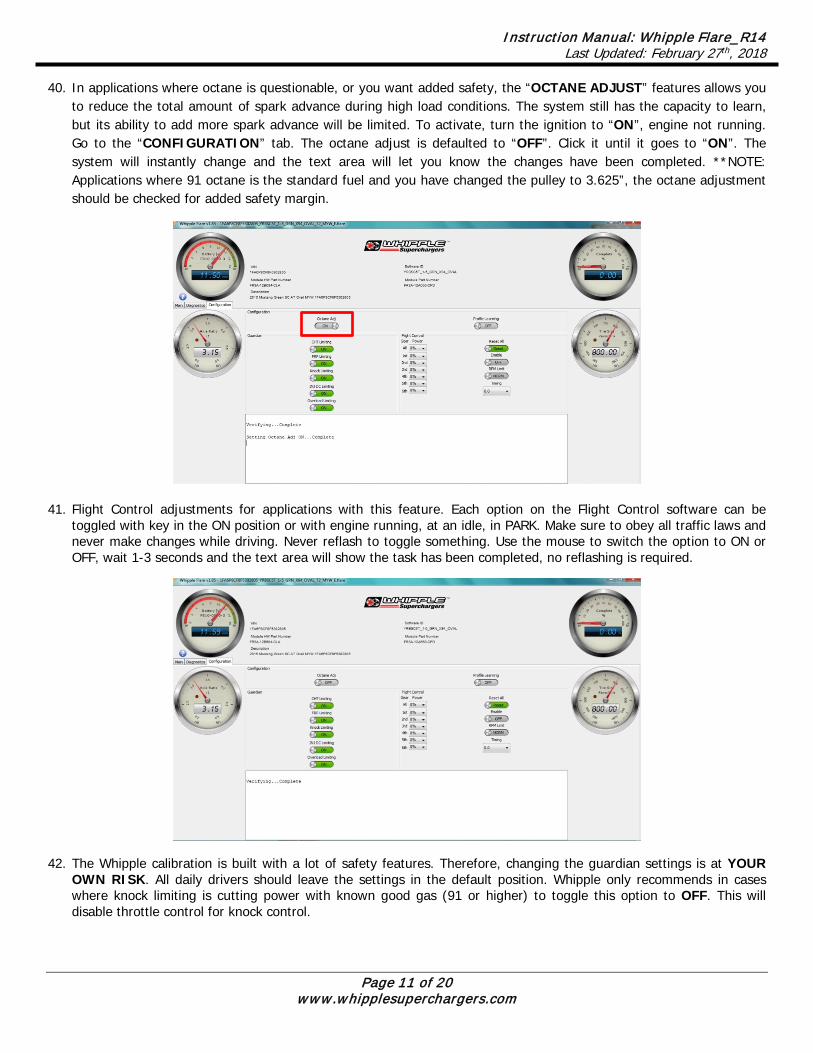
40. In applications where octane is questionable, or you want added safety, the “OCTANE ADJUST” features allows you to reduce the total amount of spark advance during high load conditions. The system still has the capacity to learn, but its ability to add more spark advance will be limited. To activate, turn the ignition to “ON”, engine not running. Go to the “CONFIGURATION” tab. The octane adjust is defaulted to “OFF”. Click it until it goes to “ON”. The system will instantly change and the text area will let you know the changes have been completed. **NOTE: Applications where 91 octane is the standard fuel and you have changed the pulley to 3.625”, the octane adjustment should be checked for added safety margin.
41. Flight Control adjustments for applications with this feature. Each option on the Flight Control software can be toggled with key in the ON position or with engine running, at an idle, in PARK. Make sure to obey all traffic laws and never make changes while driving. Never reflash to toggle something. Use the mouse to switch the option to ON or OFF, wait 1-3 seconds and the text area will show the task has been completed, no reflashing is required.
42. The Whipple calibration is built with a lot of safety features. Therefore, changing the guardian settings is at YOUR OWN RISK. All daily drivers should leave the settings in the default position. Whipple only recommends in cases where knock limiting is cutting power with known good gas (91 or higher) to toggle this option to OFF. This will disable throttle control for knock control.

Instruction Manual: Whipple Flare_R14 Last Updated: February 27th, 2018
Page 12 of 20 www.whipplesuperchargers.com
CHT Limiting: The Cylinder Head Limiting temperature limiting feature is for applications intended for racing in control events. This will reduce the amount of added safety based off of the factory Cylinder Head Temp. This reduces spark advance to add safety when racing and coolant temps are not maintained. All knock sensor and other safety features are still on. FRP Limiting: The factory fuel system does not include a fuel pressure sensor. Whipple Superchargers offers a fuel rail pressure sensor to add increased safety for systems where the stock fuel system may reach its limit. The FRP limit will adapt before the fuel trims so the predictions will be more accurate for fuel pressure falling. The FRP limit will also cut power when the fuel system reaches a critical supply level. This system only works when the FRP sensor is installed and wired. This can be left on or toggled off, it will not change until the sensor is installed. Knock Limit: This feature is defaulted on and works off the factory knock sensors. It constantly monitors knock events, in cases where you have poor gas or another issue and the knock sensor activity becomes too active, the knock limit reduces power output (cylinder pressure) by holding the throttle back until the knock activity has reduced for a calibrated time. When this featured is toggled OFF, the system will work as normal where the knock sensor is active for advancing/retarding. INJ DC Limiting: This feature allows the customer to toggle the pre-defined “MAX” fuel injector duty cycle limit in applications where the fuel injector may be prematurely clipping the targeted power level. This should only be toggled off in a race application after discussing with Whipple. Overload Limiting: This feature consistently monitors airflow vs its torque output and consistently adapts to the environment. When a customer changes the pulley that can exceed the fuel and air calibration, the PCM recognizes the changes and limits the capacity. Reset All: The reset all feature allows you to revert back all changes you have made from the default settings. Default settings are recommended for all daily drivers. Enable: The enable mode is for RACE APPLICATIONS ONLY. NEVER USE WITH PUMP GAS, ONLY FOR RACE APPLICATIONS USED ON CLOSED COURSES. In applications with aftermarket valve train and other changes that may create false knock readings, the Enable mode disables knock control and runs the standard calibrated timing curve (no adding/subtracting). RPM Limit: The RPM limit change feature gives you two RPM limit set points. Stage 1 base RPM limit = 7200RPM Stage 1 optional RPM limit = 7500RPM Stage 2 base RPM limit = 7500RPM Stage 2 optional RPM limit = 7800RPM Note that automatic transmission vehicles will still have a lower targeted shift RPM. Whipple recommends 7500rpm for all standard applications. Timing: The timing feature is tied to the “Enable” function. When the Enable is off, the timing adjustment does not make a difference. When the timing mode is ON, this is the adder/subtractor to the base timing system. NEVER USE WITH PUMP GAS, ONLY FOR RACE APPLICATIONS USED ON CLOSED COURSES.
Flight Control: The Flight Control software allows the user to lower power per gear or overall. The percent changes are at 5% increments and are changing the available power by pre-determined power levels. 25% will result in near stock power levels and is intended for applications where you want the car to have little to no extra power, possibly during poor weather, taking to dealer, loaning the car and many other scenarios may fit. In race applications where traction is an issue, the power per gear can be a useful tool to bring your power down to a track-able power level in the first few gears.
Instruction Manual: Whipple Flare_R14 Last Updated: February 27th, 2018
Page 13 of 20 www.whipplesuperchargers.com
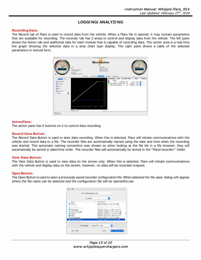
LOGGING/ANALYZING Recording Data: The Record tab of Flare is used to record data from the vehicle. When a Flare file is opened, it may contain parameters that are available for recording. The recorder tab has 3 areas to control and display data from the vehicle. The left pane shows the Action tab and additional tabs for each module that is capable of recording data. The center area is a real time live graph showing the selected data in a strip chart type display. The right pane shows a table of the selected parameters in textual form.
Action Pane: The action pane has 5 buttons on it to control data recording. Record Data Button: The Record Data Button is used to start data recording. When this is selected, Flare will initiate communications with the vehicle and record data to a file. The recorder files are automatically named using the date and time when the recording was started. This automatic naming convention was chosen so when looking at the file list in a file browser, they will automatically be sorted in date/time order. The recorder files will automatically be stored in the “Flare/recorder/” folder. View Data Button: The View Data Button is used to view data on the screen only. When this is selected, Flare will initiate communications with the vehicle and display data on the screen, however, no data will be recorded or saved. Open Button: The Open Button is used to open a previously saved recorder configuration file. When selected the file open dialog will appear where the file name can be selected and the configuration file will be opened for use.

Instruction Manual: Whipple Flare_R14 Last Updated: February 27th, 2018
Page 14 of 20 www.whipplesuperchargers.com
Save Button: The Save Button is used to Save the current data set configuration to a file so it can be opened at a later time. When selected the file save dialog will appear where the filename can be entered and save the configuration file for later use.
Remove All Button: The Remove All Button is used to remove all parameters in the recorder list. English/Metric/Module Unit Selection: The Unit combo box is used to select the unit to display on the screen. Data is always recorded in module units. Module Panes: One or more module panes may be visible which is dependent on the Flare file that is opened, but most files will only have the Powertrain Control Module (PCM). This pane is a list of parameters that are available to be recorded. Simply double click on the parameter and it will be added to the list in the table pane.
Graph Pane: The graph pane contains the latest 60 seconds of data that has been received by Flare. The graph can be “zoomed” in by changing the X Range value at the bottom of the graph pane. This is the amount of time that will be visible in seconds. This can be changed while the recording is running and the scroll bar will allow scrolling around within the 60 seconds of data. Each parameter is plotted using its own Y axis and the range of the Y axis will be automatically scaled if the Min/Max fields in the table are cleared. The range of the Y Axis for each parameter can also be adjusted by typing values into the Min/Max fields. Table Pane: The Table Pane contains the textual display of the data that is received from the vehicle and controls of each parameter display characteristics.

Instruction Manual: Whipple Flare_R14 Last Updated: February 27th, 2018
Page 15 of 20 www.whipplesuperchargers.com
“V” Column: The V column is used for 2 purposes; first to turn the graph for that parameter on/off by clicking on the color for that parameter. Right clicking on the V column will bring up the color selector so the color of the parameter can be changed. When recording, even if the parameter is not displayed on the real time graph, it is still being recorded to the file. Parameter Column: The parameter column displays the name of the parameter. If this column is clicked, the Y Axis for that parameter will be turned on/off. Value Column: The value column displays the latest value of each parameter. Unit Column: The unit column will display the unit for the parameter and may change based on the units that are selected. i.e. temperatures will be displayed in degrees F for English units and degrees C for metric units. Min/Max Columns: The Min/Max columns are used to control the range of the Y Axis for each parameter that will be displayed. These can be changed while the recording is running. Rate Column: Flare has the ability to record data at high and low speeds simultaneously. High speed recording is limited in the number of parameters that can be recorded simultaneously. Flare will add parameters to the high-speed list first and when there is no space available automatically start adding them to the low speed list. Not all parameters need to be recorded at the high data rate such as temperature data. The combo box in the rate column is used to select the data rate for each parameter. Remove Column: Clicking the remove column will that particular parameter from the recorder list. Marker Parameter: Whenever parameters are added, there is a special “Marker” parameter that is always added. This is used to “Mark” a special area of interest in the recording. This is done while recording by pressing the space bar. This marker is a simple counter that will increment each time the space bar is pressed.

Instruction Manual: Whipple Flare_R14 Last Updated: February 27th, 2018
Page 16 of 20 www.whipplesuperchargers.com
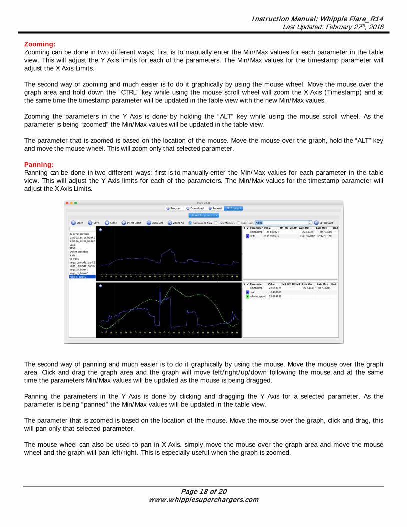
Analyzing Data: The Analyze tab is used to open and display data from recorder files. This tab is very similar to the recording tab in its layout and usage. On the left is the button pane which is used to open, close, save and switch graph layouts. The center section is the graphical display of the recorded data and on the right is the tabular display of the data. When a recorder file is opened, the analyze tab will be displayed as shown below.
Open Button: The open button is used to open a recorder file. Save Button: The save button is used to save the currently open recorder file. All items of the recorder file are saved to the same file that is opened including all modifications that were made to each of the parameters in the table pane. Close Button: The close button is used to close the currently open recorder file. Insert Chart Button: The insert chart button is used to insert another chart where recorded parameters can be viewed. Auto Size Button: The auto size button will arrange the all the charts. Zoom All Button: The zoom all button will zoom the extents of the recorded data. Common X Axis Checkbox: The common x axis checkbox allows all charts to share the same time axis (x) or use individual ones for each chart. If the check box is selected, all charts will move together along the time axis. If the check box is cleared, each chart can individually be moved long the time axis.

Instruction Manual: Whipple Flare_R14 Last Updated: February 27th, 2018
Page 17 of 20 www.whipplesuperchargers.com
Lock Markers Checkbox: The lock markers checkbox allows the 2 markers “M1” and “M2” to be moved together. If the checkbox is clear, the markers can be moved individually. Gridlines Checkbox: The gridlines checkbox will turn on/off the vertical grid lines. Layout Selection: The layout selection box is used to recall any saved layouts. The layout is a fast-convenient way of storing your own layouts including the number of graphs, data on each graph and the content of each parameters' settings. To save a layout, simply click in the layout box and type a new name and the current layout will be saved and be able to be recalled at a later time. Set Default Button: The set default button is used to set the default layout whenever a new recorder file is opened. When new data is recorded, there is no layout information in the recorder file. When the new file is opened, the default layout will be used to arrange the view. Graph Pane The graph pane displays the open recorder file in graphical form. The X axis (Timestamp) is the recorded timestamp and each parameter has its own Y Axis (vertical). Both the X Axis and Y Axis can be controlled using the Pan and Zoom operations.
Adding Parameters to a Chart: To add a parameter to a chart, click and drag & drop the parameter from the parameter list on the left to the to the chart and the recorded data will be added to the graph and an entry in the table will be created. Multiple parameters can be selected in the parameter list and added at the time by holding the CTRL (Command Key on MAC) key and selecting each parameter and then drag and drop all the selected parameters to a chart. This will add all the selected parameters in one operation. Inserting Charts: To insert a new chart, click the “Insert Chart” button on the toolbar. This will insert a new chart where other parameters can be graphed. This can be used to group similar parameters together into a single chart. To remove a chart, click the “X” button at the top left corner of the chart.
Instruction Manual: Whipple Flare_R14 Last Updated: February 27th, 2018
Page 18 of 20 www.whipplesuperchargers.com
Zooming: Zooming can be done in two different ways; first is to manually enter the Min/Max values for each parameter in the table view. This will adjust the Y Axis limits for each of the parameters. The Min/Max values for the timestamp parameter will adjust the X Axis Limits. The second way of zooming and much easier is to do it graphically by using the mouse wheel. Move the mouse over the graph area and hold down the “CTRL” key while using the mouse scroll wheel will zoom the X Axis (Timestamp) and at the same time the timestamp parameter will be updated in the table view with the new Min/Max values. Zooming the parameters in the Y Axis is done by holding the “ALT” key while using the mouse scroll wheel. As the parameter is being “zoomed” the Min/Max values will be updated in the table view. The parameter that is zoomed is based on the location of the mouse. Move the mouse over the graph, hold the “ALT” key and move the mouse wheel. This will zoom only that selected parameter. Panning: Panning can be done in two different ways; first is to manually enter the Min/Max values for each parameter in the table view. This will adjust the Y Axis limits for each of the parameters. The Min/Max values for the timestamp parameter will adjust the X Axis Limits.
The second way of panning and much easier is to do it graphically by using the mouse. Move the mouse over the graph area. Click and drag the graph area and the graph will move left/right/up/down following the mouse and at the same time the parameters Min/Max values will be updated as the mouse is being dragged. Panning the parameters in the Y Axis is done by clicking and dragging the Y Axis for a selected parameter. As the parameter is being “panned” the Min/Max values will be updated in the table view. The parameter that is zoomed is based on the location of the mouse. Move the mouse over the graph, click and drag, this will pan only that selected parameter. The mouse wheel can also be used to pan in X Axis. simply move the mouse over the graph area and move the mouse wheel and the graph will pan left/right. This is especially useful when the graph is zoomed.

Instruction Manual: Whipple Flare_R14 Last Updated: February 27th, 2018
Page 19 of 20 www.whipplesuperchargers.com
Current Value Marker & Static Markers (M1 & M2): There are 3 markers on the graphical display. The gray colored marker will always follow the mouse location and update the table view with the value at that point. There are also two static markers that can be placed that will stay where they are placed. To place marker M1, simply move over the graph area and click the mouse button. This will place marker M1. To place marker M2, move over the graph area press the “SHIFT” key and click the mouse button. This will place marker M2. When either of the markers are placed the M1/M2 columns and the M1-M2 column for each parameter will be updated with the value at that location in the graph. Table Pane: The Table Pane contains the textual display of the data that is stored in the recorder fle and controls of each parameter display characteristics.
“X” Column: The X column is used to remove a parameter from a chart. “V” Column: The V column is used for 2 purposes; first to turn the graph for that parameter on/off by clicking on the color for that parameter. Right clicking on the V column will bring up the color selector so the color of the parameter can be changed. The file must be saved to save the color of the parameter. Parameter Column: The parameter column displays the name of the parameter. If this column is clicked, the Y Axis for that parameter will be turned on/off. Hovering over the parameter name will also display a tooltip that contains the value, M1, M2, M1-M2, Min and Max table cells for that parameter. Clicking on the parameter name will also show/hide the y-axis for that parameter.
Instruction Manual: Whipple Flare_R14 Last Updated: February 27th, 2018
Page 20 of 20 www.whipplesuperchargers.com
Value Column: The value column displays the value at the gray marker location. As the mouse is moved across the graph area, this value will be updated. M1, M2 and M1-M2 Columns: These three columns will contain the values of each of the static markers that are placed on the graph. The M1 column will display the value of each parameter at the M1 Marker location. The M2 column will display the value of each parameter at the M2 Marker location. The M1-M2 column will display the difference between the M1 and M2 markers for each parameter. Unit Column: The unit column will display the unit for the parameter and may change based on the units that are selected. i.e. temperatures will be displayed in degrees F for English units and degrees C for metric units. Axis Min/Max Columns: The Axis Min/Max columns are used to control the range of the Y Axis for each parameter that will be displayed. These values can be used to set the range of multiple parameters to the same extents. If either the Min or Max values are blank, the graph for that parameter will be auto-scaled. To set multiple min/max values at the same time, select multiple cells in the table and type the value. This same value will be set on all the selected cells.