Embed Size (px)
Citation preview

www.ilogix.com© I-Logix 2004 Tampere OO day 14/12/2004
What's New in UML 2.0
M.W.RichardsonLead Applications Engineer
I-Logix [email protected]

www.ilogix.com© I-Logix 2004 Tampere OO day 14/12/2004
What is UML?Unified Modeling LanguageComprehensive full life-cycle 3rd Generation modeling language
Standardized in 1997 by the OMGCreated by a consortium of 12 companies from various domainsI-Logix a key contributor to behavioral modeling
Incorporates state of the art Software and Systems A&D concepts Matches the growing complexity of real-time systems
Large scale systems, Networking, Web enabling, Data management
Extensible and configurableUnprecedented inter-disciplinary market penetrationUML 2.0 is latest version in the process of being released

www.ilogix.com© I-Logix 2004 Tampere OO day 14/12/2004
Advent of the UML
Mid 70s – Late 80s
Identifiable OO modelling languages began to appear
1989 1994
No Of Identifiable OO Modelling Languages Increases from <10 to >50
“Method Wars” Begin!
Methods begin to merge
1995
Grady Booch and Jim Rumbaugh begin unifying Booch & OMT
Ivar Jacobson (Objectory) join
them and add OOSE
1996
UML 0.9 & 0.91 Released
OMG Issues RFP
1997
RFP Response for UML 1.0
UML 1.1
1999
UML 1.3
UML 1.4
2001
UML 2.0
2004 2004+
UML 0.6 - Dr David Harel adds Statecharts
OOSE = Object Oriented Software Engineering MethodOMT = Object Modelling Technique
www.ilogix.com© I-Logix 2004 Tampere OO day 14/12/2004
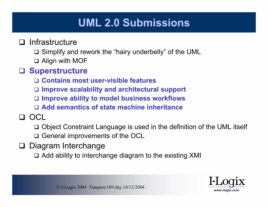
UML 2.0 SubmissionsInfrastructure
Simplify and rework the “hairy underbelly” of the UMLAlign with MOF
SuperstructureContains most user-visible featuresImprove scalability and architectural supportImprove ability to model business workflowsAdd semantics of state machine inheritance
OCLObject Constraint Language is used in the definition of the UML itselfGeneral improvements of the OCL
Diagram InterchangeAdd ability to interchange diagram to the existing XMI

www.ilogix.com© I-Logix 2004 Tampere OO day 14/12/2004
UML 2.0 Diagrams
Communication Diagrams
Sequence Diagrams
Interaction Diagrams
Class Diagrams
DeploymentDiagrams
ComponentDiagrams
Object Diagrams
Structural Diagrams
State Machine Diagrams
Timing Diagrams
Activity Diagrams
Behavioral Diagrams
Use CaseDiagrams
PackageDiagramsStructure
Diagrams
Interaction Diagrams

www.ilogix.com© I-Logix 2004 Tampere OO day 14/12/2004
Ports & Ports & Structured ClassesStructured Classes

www.ilogix.com© I-Logix 2004 Tampere OO day 14/12/2004
How can we model the following in UML?

www.ilogix.com© I-Logix 2004 Tampere OO day 14/12/2004
PC System with UML 1.5
www.ilogix.com© I-Logix 2004 Tampere OO day 14/12/2004
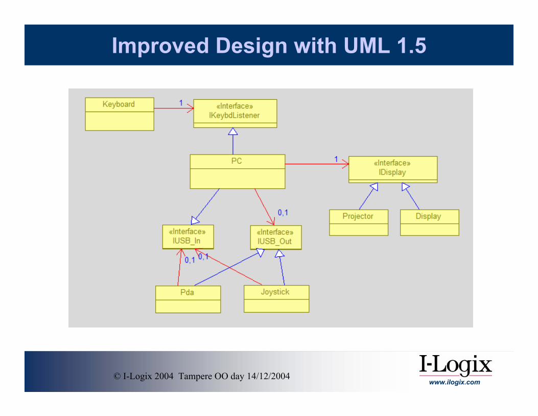
Improved Design with UML 1.5

www.ilogix.com© I-Logix 2004 Tampere OO day 14/12/2004
Internal View of PC
Problem: Not obvious that the instance of Motherboard created by the PC is connected to the instances of USBCard and GraphicsCard created by the PC.

www.ilogix.com© I-Logix 2004 Tampere OO day 14/12/2004
PC System
Problem: No way to cleanly specify which instance of pc is connected to which instance of Keyboard

www.ilogix.com© I-Logix 2004 Tampere OO day 14/12/2004
UML 2.0 Ports
Ports are “named connection points”Ports allow a part to provide an interface across the boundary of its enclosing structured class without revealing to the client of the service the internal structure of the structured class
Client “talks to” the port without internal knowledge
Ports are “typed by” their interfacesProvided interfaces Required interfaces
These interfaces can consist of synchronous and / or asynchronous operations

www.ilogix.com© I-Logix 2004 Tampere OO day 14/12/2004
UML 2.0 Ports
ProvidedContract
RequiredContract
Port

www.ilogix.com© I-Logix 2004 Tampere OO day 14/12/2004
Devices

www.ilogix.com© I-Logix 2004 Tampere OO day 14/12/2004
PC System : Plug & Play
Connector
PartStructured
Class

www.ilogix.com© I-Logix 2004 Tampere OO day 14/12/2004
PC InternalsRelay Port
Behavioral Port
Note here that the PC actually does nothing, all the external ports are connected to internal parts.

www.ilogix.com© I-Logix 2004 Tampere OO day 14/12/2004
Things to Remember about PortsPorts are optional!
There is NOTHING you can do with ports that you can’t do without them
Ports enforce encapsulation of internal partsParts can publish services across the boundary of their owning composite classes without revealing the to the client of the service which part offers itParts are typed by interfaces
• Compatible ports are “conjugates” – one offers, the other requires the same or compatible interface
• Sub-classed provided interfaces are compatible with super-class required interfaces
Ports are a design patternAll design patterns have pros and cons
• Con: Ports are instantiable and so take up some amount of memory and require some amount of execution time
Ports are implemented by classes that provide behavioral delegation services to their clients
Ports can have multiplicity and can be connected dynamically

www.ilogix.com© I-Logix 2004 Tampere OO day 14/12/2004
Ports Example

www.ilogix.com© I-Logix 2004 Tampere OO day 14/12/2004
Easy testing

www.ilogix.com© I-Logix 2004 Tampere OO day 14/12/2004
White Box View

www.ilogix.com© I-Logix 2004 Tampere OO day 14/12/2004
SequenceSequenceDiagramsDiagrams

www.ilogix.com© I-Logix 2004 Tampere OO day 14/12/2004
Messaging between structured classes
Horizontal Decomposition
InteractionOccurrence

www.ilogix.com© I-Logix 2004 Tampere OO day 14/12/2004
Messaging between structured classes
Vertical Decomposition
Part Decomposition

www.ilogix.com© I-Logix 2004 Tampere OO day 14/12/2004
Interaction Fragment Operatorssd – named sequence diagramref – reference to “interaction fragment”loop – repeat interaction fragmentopt – optional “exemplar”alt – selectionpar – concurrent (parallel) regionsseq – partial ordering (default) (aka “weak”)strict – strict orderingcriticalRegion – identifies “atomic” fragmentsassert – required (i.e. causal)neg – “can’t happen” or a negative specificationIgnore/consider – messages outside/inside causal stream
Flow of Control
Naming
Ordering
Causality

www.ilogix.com© I-Logix 2004 Tampere OO day 14/12/2004
Interaction Operator : Loop

www.ilogix.com© I-Logix 2004 Tampere OO day 14/12/2004
Interaction Operator : Opt

www.ilogix.com© I-Logix 2004 Tampere OO day 14/12/2004
Interaction Operators : Critical Region

www.ilogix.com© I-Logix 2004 Tampere OO day 14/12/2004
InheritedInheritedState State BehaviourBehaviour

www.ilogix.com© I-Logix 2004 Tampere OO day 14/12/2004
Inherited State BehaviorAssumes Liskov substitution principle for generalization:
You canAdd new statesElaborate sub-states in inherited statesAdd new transitions and actions
You cannotDelete inherited transitions or states
A subclass must be freely substitutable for the super-class in any operation

www.ilogix.com© I-Logix 2004 Tampere OO day 14/12/2004
Example: Generalization
Modified action list
New sub-states and transitions
New and-states

www.ilogix.com© I-Logix 2004 Tampere OO day 14/12/2004
ActivityActivityDiagramsDiagrams

www.ilogix.com© I-Logix 2004 Tampere OO day 14/12/2004
Activity Diagrams
Joint 1 to a Joint 2 to b Openmanipulator
Compute jointangles (a,b)
Grasp Object
Rotatemanipulator
interruptablesection
event reception
swim lane representingthe objects executing
the activities nestedwithin
graspAt
Joint_1 Joint_2 Joint_3
Emergency Stopinterrupting edge
Position
Proximity Alert
Interruptingedge
Event receptionor exception
Interruptibleregion
Inputpin

www.ilogix.com© I-Logix 2004 Tampere OO day 14/12/2004
TimingTimingDiagramsDiagrams

www.ilogix.com© I-Logix 2004 Tampere OO day 14/12/2004
Timing Diagram
Time
Sending::Low
Sending::High
Receving::Low
Receiving::High
Sending
Receiving
Idle
Coil Driver
Transceiver
transmit(value)
Tristate
MonitorInitializing
Acquiring
ReportingIdle
send(value)
send(value)
tm(bitTime)
{1 ms +/- 0.2ms}
{3 ms +/- 0.2ms}
evDone
A Timing Diagram shows the timing between objects.

www.ilogix.com© I-Logix 2004 Tampere OO day 14/12/2004
UML 2.0 Summary
Makes it easier to construct scaleable architecturesMakes exchange of models between tools possibleFacilitates use of UML by Systems Engineers


![[Tut]How to Crack WPA_2-PSK W_ BT4 [Tut]](https://img.dokumen.tips/doc/110x75/577d28121a28ab4e1ea52a3b/tuthow-to-crack-wpa2-psk-w-bt4-tut.jpg)