Embed Size (px)
Citation preview
Product Safety Newsletter • Page 1
What's Inside
Vol. 6, No. 1 Jan-Feb 1993
Chairman’s Message
There are two events occurring in severalmonths that deserve our attention now: theannual International EMC Symposium in
August and the election of new central committeeofficers.
TheProductSafetyNewsletter
Continued on page 19
Chairman's Message ................................ 1
Officers of the PSTC's ............................. 2
News and Notes ....................................... 3
Technically Speaking .............................. 4
New ANSI/ISA S82.01 ............................ 5
NFPA Code Revision ............................... 6
Employment Wanted ............................... 21
Institutional Listings ................................ 22
1993 International SymposiumThe Product Safety Technical Committee (TC-8) hastwo events of special interest at the Dallas Sympo-sium the week of August 9. On Thursday afternoon,immediately following the last technical sessions, wewill have our annual meeting. This is an excellentopportunity for each of you to have a voice in thedirection of the Committee as a whole. We scheduledit late in the week because of the second importantevent at the Symposium, our product safety work-shop, to be held Friday morning. Murlin Marks isheading up this effort and if the advance program isany indication, it’s going to be an excellent work-shop. Plan on attending both events when you’re inDallas.
New LeadersThis term is going by very quickly and it’s time tobegin the process of selecting new central committee
Product Safety Newsletter • Page 2
The
ProductSafetyNewsletter
Officers of the Product SafetyTechnical Committees
Central PSTC (TC-8)Chairman Brian Claes (408) 578 5035Vice-Chair Richard Pescatore (408) 447 6607Secretary-Treasurer John McBain (408) 746 5016
(408) 746 5258 (fax)Standards Jim To (408) 492 9101
(408) 492 7244 (fax)Paper Review Mike Harris (707) 258 1360Symposium Mark Montrose (408) 247 5715
Austin TexasChair Bob Hunter (512) 250 6878
Central TexasChair Pro Tem Vic Baldwin (512) 469 7289
ChicagoChair Dick Hagedorn (708) 505 5722Vice-Chair John Allen (708) 827 7520
Orange County/Southern California Chair Charlie Bayhi (714) 367 0919Vice-Chair Ercell Bryant (714) 966 3459Secretary/Treasurer Deborah Tinsley (714) 773 7977Program Co-Chair Michael Dastmalchian (310) 604 8739Program Co-Chair Ray Jimenez (619) 726 9303
PortlandChair Jim Pierce (503) 626 6694Secretary-Treasurer Scott Varner (503) 656 8841
San DiegoChair Gene Biggs (619) 592 8236Secretary-Treasurer Jo Ann Fowler (619) 592 8163Program Chair Tom Radley (619) 592 8104
Santa Clara ValleyChairman Mike Campi (408) 987 6527Vice/Program Chair Murlin Marks (408) 985 2400 X2353Treasurer Mark Montrose (408) 247 5715Secretary John Reynolds (408) 390 1344
SeattleChairman Walt Hart (206) 356 5177Membership Chair Heber Farnsworth (206) 356 6045
The Product Safety Newsletter is pub-
lished bimonthly by the Product Safety
Technical Committee of the IEEE EMC
Society. No part of this newsletter may
be reproduced without written permis-
sion of the authors. All rights to the
articles remain with the authors.
Opinions expressed in this newsletter
are those of the authors and do not
necessarily represent the opinions of
the Technical Committee or its mem-
bers. Indeed, there may be and often
are substantial disagreements with
some of the opinions expressed by the
authors.
Subscriptions are free. To receive a
subscription, send your request to:
PSN Subscriptions,
Dave McChesney
1865 Farndon Avenue
Los Altos, CA 94024
fax: (408) 296 3256
Comments and questions about the
newsletter may be addressed to:
The Product Safety Newsletter,
Roger Volgstadt (Loc. 55-53)
c/o Tandem Computers
10300 North Tantau Avenue
Cupertino, CA 95014
Fax No. (408) 285 2553
Editor: Roger Volgstadt
News Editor: David Edmunds
Abstracts Editor: Dave Lorusso
Page Layout: Ken Warwick
Subscriptions: John McBain
Ads: Ervin Gomez

Product Safety Newsletter • Page 3
News and Notes
Continued on page 18
by Dave Edmunds
News and Notes Editor
Product Safety Workshop UpdateOnce again the Product Safety Technical Committee(TC-8) of the EMC Society is sponsoring a workshopat the International EMC Symposium, held this yearin Dallas, Texas. The workshop is scheduled forFriday morning from 8:00 until 11:45 on August 13.The following program is presently blocked out:
1. Product Stewardship - Barbara Hill, IBM. Envi-ronmentally friendly design. Define and discusslarger product safety considerations than tradi-tionally utilized.
2. Snapshot of Harmonization - Panel led by BobHunter, Austin TX. Panel: Scott Barrows, Inter-national Compliance Corporation, plus 1-2 TBD.The latest global specs and considerations.
3. Failure Analysis Forensics - Brian Claes, TC-8Chairman. A structured approach to analyzingfailures and accidents.
4. Casualty Hazard Analysis - Bob Florczyk, Un-derwriters Laboratories. Discuss UL's casualtyhazard evaluation methodology. Moving parts,sharp edges, pinch points, etc.
5. Product Safety Techniques for the EMC Profes-sional - Mark Montrose. Product safety appliedengineering. Tips and considerations with appli-cation rather than theory in mind.
The session will be chaired by Murlin Marks, Under-writers Laboratories, who may be contacted at 408-985-2400. Hope to see you there!
Revision of Laser StandardA second amendment to IEC 825 Laser Safety isunder the voting procedure with a cutoff date of May31, 1993. This amendment increases the AEL fordevices operating in the IR spectrum and brings thecontrol measures closer to agreement with the FDALaser Product Performance Standard. The appendixhas a rational that explains the reason for the amend-ment.
A DIS (Draft International Standard) which will be apart 2 of IEC 825 and is titled “Safety of Optical FiberCommunication Systems” is in the voting processwith a close date of May 31, 1993.

Product Safety Newsletter • Page 4
Technically Speaking
© 1992by Richard Nute
BODY RESISTANCE
— A REVIEW
Underwriters Laboratories did basic researchin the field of safety and published theresults of that research in a series of “Bul-
letins of Research.” At least 58 bulletins were pub-lished relating to fire, explosion, and electric shock.
One of those Bulletins, “Electric Shock as it Pertainsto the Electric Fence,” is a classic document in thefield of product safety. The research was performedfrom 1936 to 1939 by Baron Whitaker, an AssistantElectrical Engineer at UL. Whitaker ultimately as-cended to the presidency of UL.
Whitaker’s research still stands today. While similarresearch has been done in support of modern IECpublications, such research is usually published onlyin IEC committee papers and is usually highly fo-cused towards the specific standard or report the IECis attempting to write.
This UL Bulletin of Research on the electric fencecontains much information that applies to much morethan just the electric fence. This is why it is a classicwork.
INTRODUCTIONWhitaker introduces his research by describing theelectric fence: “One of the most recent and novelapplications of electricity in the rural areas today isthe electric fence. Physically, the electric fencediffers from the conventional type of barbed-wire orwoven-wire fence in that it is of simpler construction(usually having one wire) and does not require themechanical strength or stability of the older types.Functionally, it is different in that it controls animalsby means of fear rather than by strength or by causingpain. The electric fence is composed of two distinctparts, namely, the fence wire, and the electriccontroller which supplies the electrical energy to thefence wire.”
PURPOSE AND CONDITIONSWhitaker studied electric fence accident reports in-volving both electric shock injury and electric-shock-caused death. Based on his study, he bounded hisresearch by stating that the electric fence should besafe for a two-year-old child, “...barefooted, stand-ing in a pool of water or mud, and falling across or
Continued on page 10

Product Safety Newsletter • Page 5
The New ANSI/ISA S82.01
Continued on page 19
by Richard C. Masek, P.E.
The Instrument Society of America SP82.02committee recently proposed a significantrevision to the ANSI/ISA SP82.01 Standard
for Electrical and Electronic Test, Measuring, Con-trolling and Related Equipment. The significance ofthis revision is it reflects a substantial effort byUnderwriters Laboratories (UL), the Canadian Stan-dards Association (CSA), and the Instrument Societyof America (ISA) to harmonize with the InternationalStandard IEC 1010-1.
Although, it is expected that the revision will have aminimal impact on manufacturers, the following is asummary of those revisions that are likely to requirechanges in the product:
- It will require better instructions to theuser in terms of the environment (i.e.limits on condensation and transients) andon the need for safety shut-down switchesif there are external moving parts.
- Hydrostatic testing will be extended toinclude equipment operating on pressures aslow as 7-1/2 psig and even lower if failurecould result in a hazard.
- Additional markings will be required forfuses and measuring terminals.
- Spacings must withstand a 10 N force.
- Various limits have been imposed if theequipment generates ionizing, laser, UV, ormicrowave radiation or generates sound orultrasound.
The IEC 1010-1 Standard was approved in 1990 andwas accepted by the United States and 12 othernations. Canada is preparing to obsolete three stan-dards C22.2 No. 142, No. 151, and No. 231 andreplace them with a new Canadian standard CSAC22.2 No. 1010.1. It will be necessary to retain C22.2No. 142 for a short while since it covers the additionalrequirements for products used in extended environ-ments such as outdoor use and ambient temperaturesabove 25°C. Underwriters Laboratories is preparingto revise UL 1244 and UL 1262 to harmonize withIEC 1010-1.
The North American approach was to adopt the textof the IEC 1010-1 standard in toto. A NationalForward explains the additional requirements orchanges to requirements which are necessary in NorthAmerica. The UL and ISA National Forwards areexpected to be essentially identical. At this time thereare about 10 differences between the North Americanand the Canadian documents. The ISA standard willadd two informative annexes to provide cross refer-ences to relevant CSA standards.
One reason for the National Forward is the use ofconduit. Although this wiring method is popular inNorth America, it is rarely used in other countries.Since it is so rare, the IEC 1010- 1 did not provide therequirements for conduit. A significant portion of theNational Forward is to identify conduit requirements.

Product Safety Newsletter • Page 6
By D. Bruce Langmuir, P.E.,Bose CorporationChairman, NCSA Product Safety Group’s Loud-speaker Standards Subcommittee
[The following article, originally titled “ ComputerIndustry Stands by while they are excluded fromNFPA Air Handling Plenum Code Revision”, isbeing reprinted with permission from the North EastProduct Safety Committee’s NPSS Newsletter ofMarch, 1993. Our thanks to Tony Nikolassy, Editor ofthe Newsletter. - Ed.]
Three and a half year ago the trade associationof commercial loudspeakers, the NationalSound & Communications Association
(NSCA), started working on revising a building codeto officially permit installation of discrete products inair-handling plenum spaces. At this time, NSCArepeatedly invited the computer industry to join inand assist in the effort. The computer industry feltthere was no need and stood by while the NSCAaccomplished their goal. Consequently, with thesingle exception of loudspeakers and their accesso-ries, all other discrete products, such as computersand their accessories and other electronic products,are still excluded from the code. Continuous prod-ucts, such as wire and cable, are still included in thecode as long as they meet the code requirements andare so tested and listed.
Loudspeakers, loudspeaker assemblies, and their ac-cessories are now permitted to be installed in an air-
handling space per a recently revised National FireProtection Association (NFPA) building code if theyhave been inspected and are listed as having beentested per a new Underwriters Laboratories Inc. (UL)standard for testing, UL 2043. Previously, lack ofthese codes and standards caused inconsistent levelsof safety, as code officials and local building inspec-tors had no guidelines by which they could judgeacceptability of discrete products when installed inan air-handling plenum. This caused confusion in thefield and occasionally resulted in portions of systemshaving to be removed after they had been installed.
For three and a half years, the NSCA, the ProductSafety Group’s Loudspeaker Standards Subcommit-tee has been diligently working to accomplish thisgoal. Along the way, NSCA funded a $55,000 ULFact Finding Investigation of Audio Systems for Usein Air Handling Plenum Spaces; a full-scale plenumsimulation study. From this study, a new UL teststandard, UL 2043, was developed and recentlypublished. This was the foundation of what enabledthe NSCA’s Product Safety Group to request a changeto the relevant NFPA code, NFPA-90A-1989 Instal-lation of Air Conditioning and Ventilating Systems.
At the annual fall meeting of the NFPA in Dallas,Texas, on November 18, 1992, the membership votedunanimously to add a new exception to NFPA-90A-1989. The NFPA membership voting was at theconclusion of four voting/reviewing cycles withinNFPA. This exception was requested to the NFPA-90A Committee by the NSCA Product Safety Group’sLoudspeaker Standards Subcommittee, which con-sists of Paul Fidlin (Electro-Voice Inc.), WarrenGrote (Atlas/ Soundolier), the late Jack E. Holt
Computer Industry Excludedfrom NFPA Code Revision

Product Safety Newsletter • Page 7
(Dukane Corp.), John Henley (Fourjay IndustriesInc.), Melvin Wierenga (ASCOM Inc.) and thesubcommittee’s Chairperson, Bruce Langmuir (BoseCorp.).
What follows is a quote of Section 2-3.10.1 from therevised National Fire Protection Association stan-dard NFPA-90A-1993 Installation of Air Condition-ing and Ventilating Systems, and shows the newaddition of Exception No. 2 that was requested byNSCA. The new exception No. 2 is indicated by avertical line in the left margin; there are no otherrevisions in the rest of this section.
————————————————
“2-3.10.1 Ceiling Cavity Plenum. the space betweenthe top of the finished ceiling and the underside of thefloor or roof above may be used to supply air into orreturn and/or exhaust air from the occupied area,provided that:
(a) All materials to the airflow shall be noncombus-tible or limited combustible and have a smoke devel-oped index no higher than 50.
Exception No. 1: The materials listed hereinafter arepermitted in the ceiling cavity plenum if listed ashaving a maximum peak optical density of 0.5 or less,average optical density of 0.15 or less, and maximumflame spread distance of 5 ft. (1.5 m) or less whentested in accordance with the specified test method:
(1) Electrical wires and cables - NFPA-262(2) Pneumatic tubing for control systems - UL 1820(3) Optical-fiber cables - NFPA-262(4) Fire sprinkler piping - UL 1887
Exception No. 2: The products listed hereinaftershall be permitted in the ceiling cavity plenum iflisted as having a maximum peak optical density
of 0.5 or less, average optical density of 0.15 orless, and a peak heat release rate of 100 Kilowattsor less, when tested in accordance with the speci-fied test method or standard:
(1) Loudspeakers, loudspeaker assemblies and theiraccessories - UL 2043.
(b) The integrity of firestopping penetrationsshall be maintained.
(c) Light diffusers, other than metal or glass,used in air handling light fixtures shall belisted and marked “Fixture Light Diffusersfor Air Handling Fixtures”.
(d) The temperature of air delivered to theseplenums shall not exceed 250 F (121 C).
(e) Materials used in the construction of a ceil-ing plenum shall be suitable for continuousexposure to the temperature and humidityconditions of the environment air in theplenum.
(f) Where the plenum is part of a floor-ceilingor roof-ceiling assembly which has beentested or investigated and assigned a fireresistance rating of 1 hour or more, theassembly shall meet the requirements of 3-3.3.”
———————————————
The official effective date of this revised NFPA-90A-1993 version, with the addition of Exception No. 2 asnoted above, was February 12, 1993. The new editionof NFPA-90A-1993 is scheduled to be publishedaround March, 1993.
The interpretation of accessories by the NFPA-90A

Product Safety Newsletter • Page 8
committee is that accessories include power amplifi-ers used to power loudspeakers and loudspeakerassemblies installed in air-handling plenums. It shouldbe remembered that Loudspeakers, loudspeaker as-semblies and their accessories, are the first discreteproducts to be permitted in air-handling plenums perNFPA90A. The title for the new UL standard forsafety, UL 2043, is Fire Test for Heat and VisibleSmoke Release for discrete products and their Acces-sories Installed in Air-Handling Spaces. The NSCALoudspeaker Standards Subcommittee requested thisstandard be generically written so other discreteproducts could potentially be added in the future afterbeing requested of UL and NFPA, reviewed by ULand NFPA, and the standards modified accordingly.
With this new revision of the NFPA-90A code, soundinstallation contractors can now lead the local inspec-tor to the specific Exception No. 2, which allowslisted loudspeaker products and their accessories tobe installed in air-handling plenum spaces. While thenew edition of NFPA-90A-1993 is scheduled to bepublished in 1993, unfortunately, not all municipali-ties and/or states in the USA observe the latest editionof the NFPA-90A and some don’t use it at all. In theselocalities, the sound installation contractors shouldlead the local inspector to Exception No. 2 beforeinstallation is done. In all plenum installation cases,the sound contractors should make sure their prod-ucts are appropriately listed for air-handling plenumspace use. Loudspeakers, loudspeaker assemblies,and their accessories, which are designed and listedas having been tested in accordance with UL 2043 arealready available from a few manufacturers andmany more are expected over the next 12 months. Itis suggested that sound contractors keep a copy of thisarticle until they obtain the revised copy of NFPA-90A-1993.
There is no listing category for UL 2043 because it isa test standard; a procedure for evaluating the fire
behavior of any discrete product. Products at UL areto be Listed according to product group standards forsafety, such as UL 1480, Speakers for Fire ProtectiveSignaling Systems (for UL Category Control Num-ber UUMW, Fire Protective Signaling Speakers andControl Number UEAY, General Purpose Speakers),UL 1711, Amplifiers for Fire Protective SignalingSystems (for UL Category Control Number UUMW,Fire Protective Signaling Amplifiers only), and UL813, Commercial Audio Equipment (for UL Cat-egory Control Number AZJX, General Purpose Am-plifiers). More product standards for safety listingswill be revised to include the UL 2043 test.
NSCA and I are very thankful for the assistance of anumber of NSCA loudspeaker manufacturers, the ULFire Protection Department, the UL Burglary Protec-tion and Signaling Department, the NFPA-90A Com-mittee, the NSCA Product Safety Group, and itsLoudspeaker Standards Subcommittee.
There is still work going on in this area to find outwhether or not there is in reality a problem of limitedcombustible products installed in air-handling ple-num spaces. An investigation with large-scale simu-lation plenum fire testing, using all products installedin air-handling plenum spaces, is expected to startsoon under the direction of the National Fire Protec-tion Research Foundation, an independent branch ofthe NFPA. The NSCA is staying involved, but thecomputer industry has not started yet. ❑

Product Safety Newsletter • Page 9

Product Safety Newsletter • Page 10
Technically SpeakingContinued from page 4
grasping the wire with two wet or sweaty hands, thewire, so far as the child is aware, being an ordinarynon-electrified fence wire.”
(Anecdotally, a colleague, whose home is a farm anduses electric fences, reported that these were theconditions under which his wife rescued his daugh-ter!)
Under these conditions, Whitaker wanted to deter-mine the maximum value of current, for both ac anddc, the frequency, and the duration that “can beconsidered as not being hazardous to human life.”
Whitaker undertook to determine values for:1. Body electrical resistance2. Safe open-circuit voltage.3. Effects of dc, interrupted dc, ac, and frequencyof ac.4. The maximum current and duration which will
not cause bodily injury.5. The minimum off time.
THE NATURE OF ELECTRIC SHOCKWhitaker researched the various causes of death fromelectric energy. He found five different causes:1. Paralysis of the respiratory muscles, producing
death from asphyxia.
2. Hemorrhage, produced by increasing blood pres-sure during the passage of electric current.
3. Heart failure, produced by ventricular fibrilla-tion.
4. Respiratory failure, produced by nervousinhibitions or actual damage to the nervoussystem.
5. Skin and flesh burns, with resultant complica-tions.
Whitaker’s research was oriented towards preven-tion of one or more of these injuries. He was notdealing with prevention of sensation or prevention ofreflexive action as we do in today’s products. Fur-thermore, electric fence manufacturers claimed thatan effective fence should provide sufficient currentto cause muscle contraction, and that the “off” periodshould be as short as possible.
BODY ELECTRICAL RESISTANCEWhitaker starts his consideration of body resistancewith the statement, “Necessary to the establishmentof the safe operating characteristics of electric fencecontrollers is a consideration of the human body as aconductor of electricity.”
Whitaker initiated a series of tests at UL to measurebody resistance. Whitaker asserts that “the outerskin... offers the greatest resistance...” and that thehigh voltage of a fence controller breaks down theskin resistance. But, Whitaker could not apply highvoltage, at unlimited current, to his subjects to“break down” the skin resistance. Therefore,Whitaker’s experiments included wetting the handsand feet of his subjects with 20% sodium chloridesolution.
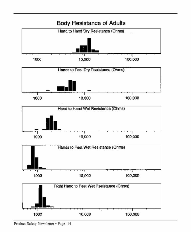
With constant area, constant pressure, and wethands, Whitaker found that the body resistance wasindependent of current, when current was in the rangeof 1 to 15 milliamperes.
Whitaker’s test set-up was comprised of a 12-volt dcsource (dry cells), a potentiometer, a voltmeter, andan ammeter. The hand electrodes were No. 10 AWGwires. The foot electrode was a 14-inch square

Product Safety Newsletter • Page 11
copper plate. The potentiometer was adjusted for 5milliamperes for adults and 1 milliampere for chil-dren. The voltage across the subject was measured,and the resistance calculated.
Whitaker measured 40 adults and 47 children (aged3 to 15). He found that, for adults, “there are notrends or relationships between the body resistance ofindividuals and their sex, age, height, or weight.” Ihave provided histograms of Whitaker’s variousmeasurements.
From this data, he concluded that “the lowest bodyresistance which might be reckoned with in connec-tion with the electric fence application would not beless than 500 ohms.”
(In a later Bulletin of Research, this same data is usedby Karl Geiges to develop the infamous leakagecurrent meter. I will review Geiges’ work in a futureissue.)
VOLTAGEWhitaker needed to determine two factors with re-spect to voltage:
1. If the output current is limited, does the open-circuit voltage would need to be controlled?
2. If the output current is not limited, what is themaximum open-circuit voltage?
Whitaker determined that the maximum safe voltage(from a voltage source where the output current is notlimited) would be that voltage that did not causebodily injury and permitted the individual to freehimself from the fence.
Whitaker reports a series of tests, performed on ULstaff during 1930, which, incidentally, recorded the
voltage that an individual could withstand and stillhave voluntary control of his muscles. From thisdata, the minimum voltage was 20 volts rms.
Whitaker also reports of tests by International Har-vester Co. where the voltage was connected to abucket filled with water and to a hand electrode heldby the subject. The subject was then asked to retrievean object immersed in the bucket. InternationalHarvester found that the maximum voltage for re-trieving the object was from 12 to 20 volts.
Whitaker concluded that “the open-circuit voltageneed not be limited provided the device incorporatesinherent current-limiting features.”
However, “where no inherent current-limiting fea-tures are incorporated in the device, the maximumsafe voltage... should not exceed 12. This is basedupon the theory that a potential of 12 volts or less willrarely, if ever, cause a breakdown of skin resistancesufficient to permit a current flow through the bodyof such intensity as to cause lack of muscular controlor physical injury to the person.”
FREQUENCYWhitaker reports that “the chief difference in thephysical effect of direct, as opposed to alternatingcurrent, is that the direct current does not causecontraction of the muscles to the extent associatedwith alternating current.”
Whitaker also notes that Kouwenhoven andd’Arsonval both found that as frequency increases,current must also increase to have the same physi-ological effect.
Nevertheless, Whitaker concludes that “there is nopresent warrant for permitting greater values ofcurrent... regardless of the frequency employed.”

Product Safety Newsletter • Page 12
CURRENTFrom the same data where Whitaker determined themaximum voltage and from other data, Whitakerdetermined that the minimum and maximum valuesat which individuals retain voluntary control ofmuscles were about 6 milliamperes and 20 milliam-peres, respectively.
Whitaker also studied the results of fibrillating cur-rent tests on dogs and sheep, as these animals’ heartswere considered to have the same response to stimu-lus as do humans. From the tests on sheep andbecause sheep have body and heart weights similar tohumans, Whitaker determined that minimum fibril-lating current is directly proportional to body weightand to heart weight.
Further study of sheep test data showed that fibrilla-tion was a function of the phase of the cardiac cycleat the time the shock occurred, and a function of theduration of the shock. Whitaker found that fibrilla-tion for a 0.1-second duration shock, required 10times the current as for a 3-second duration shock.
Whitaker then plotted 3-second fibrillation currentsfor different full-grown animals as a function of bodyweight and heart weight. Whitaker then assumedthat the minimum value of such a curve representedman. Whitaker further assumed that the minimumfibrillating current for different body and heartweights is a constant ratio, provided the shock dura-tion is the same percentage of the heart cycle, and theshock is initiated at the same point in the heart cycle.
Using these assumptions and data, Whitaker deter-mined that the minimum 3-second fibrillating currentfor 125-pounds body weight is 126 milliamperes,and for 20-pounds body weight is 31 milliamperes.(Twenty pounds is taken as the average weight of a
two-year-old child.)
Using these numbers, Whitaker determined the ratio31:126 for minimum fibrillating currents for bodyweights of 20 and 125 pounds.
Using this ratio, and accounting for percent of thetime for a complete heartbeat, for body weight, andfor heart weight, Whitaker was able to construct a“Derived Curve of Contact Time versus MinimumFibrillating Current for a Two-Year-Old Child.”This curve approximated a rectangular hyperbola.See Whitaker’s “Graph 3.”
Next, Whitaker arbitrarily set the maximum currentat 65 milliamperes, the maximum output at 4 milli-ampere-seconds, and the maximum “on” period at0.2 seconds. This “Contact Time versus AllowableCurrent” curve was a factor of 6 less than the mini-mum fibrillating current curve. See Whitaker’s“Graph 4.”
Whitaker concluded that (1) the maximum safe con-tinuous current is 5 milliamperes, and (2) the maxi-mum duration of any current should not exceed the4 milliampere-second curve.
OFF PERIODAt the time of Whitaker’s research, fence controllerssupplied successive shocks at about 1-second inter-vals. Whitaker needed to determine the minimum“off” period which would allow an individual to freehimself from the fence.
UL conducted tests where a voltage was suddenlyimpressed on an individual, and the time to releasewas recorded. This test was considered an “involun-tary” reaction. Whitaker noted that the time to per-ceive the sensation is inversely proportional to theintensity of the stimulus.

Product Safety Newsletter • Page 13
Whitaker also studied other reaction-time tests. Mostof this other test data was for “voluntary” reaction tostimuli such as touch, visual, or auditory.Whitaker also noted that muscular contraction asso-ciated with dc tended to throw the victim from theconductor, while the muscular contraction associatedwith ac tended to be impossible to let go.
Therefore, Whitaker concluded that the “off” periodfor ac controllers should be 0.90 second, and for dccontrollers should be 0.75 second.
FRIGHTWhitaker also investigated whether the fright gener-ated by inadvertent contact with a “safe” fence mightadversely affect the heart or trigger fibrillation. Themedical authorities he consulted were unable topredict such an event. One authority even went so faras to say that such a weak shock was not capable ofcausing either fright or surprise.
*****
I suggest there are some lessons to be learned fromWhitaker’s work. First, Whitaker focused on thevarious injuries caused by electric shock rather thancompliance with standards. Of course, there were nostandards at that time. Today, when we analyze a newsafety situation, we seem to do so with reference toa standard rather than to the injury.
Second, Whitaker made lots of measurements, butonly used the minimum, worst-case values found.This sort of pessimism is truly necessary in the fieldof safety. I think too often we tend to use probabilityand normal distributions rather than worst-case val-ues.
Third, Whitaker makes lots of assumptions and arbi-trary decisions, especially regarding animals repre-
senting humans. I suggest that we need to keep inmind that the values presented by Whitaker are notprecise. Many other of the values we use in the fieldof safety are likewise imprecise, but we treat them asif they were precise.
Finally, I find that we don’t do such research any-more. A colleague, J. F. Kalbach, coined a term,BOGSAT, meaning “Bunch Of Guys SittingAround Talking” to describe how a particular curvewas once developed. There was no engineering orphysical basis for the curve. Purely arbitrary. I wouldsuggest that our safety standards contain too manyrequirements from the BOGSAT process.
ACKNOWLEDGMENTSJim Pierce, ETL Testing Laboratories, dropped acopy of this UL Bulletin on my desk, asking if I hadread it. I had seen and read the Bulletin many yearsago, so the copy just sat on my desk for many months.Eventually, I picked it up and started reading. I wasimpressed with the work, and thought I wouldreview it for you.
I also want to acknowledge Henry Jones, a productsafety consultant, for his comments on electric fences.Thanks, too, to Tim Kramer of Hewlett-PackardCompany for preparing the histograms of body resis-tance.
*****
Your comments on this article are welcome. Pleaseaddress your comments to the Product Safety News-letter, Attention Roger Volgstadt, c/o TandemComputers Inc., 10300 N. Tantau Avenue, Location56, Cupertino, California 95014-0708 ❑
Product Safety Newsletter • Page 14

Product Safety Newsletter • Page 15

Product Safety Newsletter • Page 16

Product Safety Newsletter • Page 17

Product Safety Newsletter • Page 18
News and NotesContinued from page 3
European Mains Voltage 230 VMost EEC countries have decided that as of January1, 1993, equipment must be marked with a 230 Vrating. In Sweden, this 230 V marking has beenobligatory since 1991.
Electric and Magnetic FieldsIn November, 1992, the Board of Governors ofNEMA (National Electric Manufacturers Associa-tion) voted to commit $2 Million over a 5 year periodto contribute to the EMF health effects study beingjointly conducted by NIH and DOE.
More Electric and Magnetic FieldsFrom ANSI's "Standards Action," February 5, 1993:"APPROVAL SUSPENDED."ANSI/IEEE C95.1-1992, Safety Levels with Re-spect to Human Exposure to Radio Frequency Elec-tromagnetic Fields (3 kHz to 300 GHz).
"The BSR action taken on November 18, 1992, toapprove the above standard as an American NationalStandard has been appealed. Approval is thereforesuspended."
Until the appeal is resolved, the USA has no Nationalstandard for safety levels of E-M fields.
ISO 9000The Department of Defense is conducting a study todetermine if the military should replace its MIL-Q-9858 and MIL-I-4520 with ISO 9000.
The Federal Drug Administration uses ISO 9000 asits basic standard but embraces special requirements
for medical equipment.CSA Announces Certifications for the USACSA announced in their “Inform” publication datedFebruary 15, 1993 that on December 24th, 1992,CSA’s Rexdale facility was officially accredited bythe US Occupational Safety and Health Administra-tion (OSHA), as a Nationally Recognized TestingLaboratory (NRTL). The accreditation covers testingand certification to over 360 ANSI/UL standards fora wide range of electrical, electronic and other prod-ucts which require testing or certification by a NRTL,in accordance with OSHA regulations. Effectiveimmediately, CSA will accept applications for test-ing, evaluation and certification of products andcomponents to US Standards and Codes. Productscertified by CSA to US Standards, in accordance withthe terms of OSHA accreditation, will be identifiedby the CSA Mark with the indicator “NRTL”. Prod-ucts Certified by CSA to both US and CanadianStandards, and which are also intended for the Cana-dian market, will be identified with the indicator“NRTL/C” adjacent to the CSA mark. Details of theabove can be obtained from your local office of CSA.
UL Announces Certifications for CanadaUL announced that it is the first safety certificationorganization in the US to be granted CertificationOrganization (CO) and Test Organization (TO) ac-creditation for Canada by the Standards Council ofCanada. All UL facilities that handle both certifica-tion and testing will be able to certify all productcategories. Under terms of the program, UL will beable to evaluate products to Canadian National Stan-dards and Codes and authorize their clients to use anew UL mark for Canada on compliant products. Thenew mark will be the familiar UL in a circle with aletter C outside the circle at the 8 o’clock position. Asa result, UL is able to provide all certification ser-vices that are needed for its manufacturing customersto gain product acceptance and do business in both

Product Safety Newsletter • Page 19
Chairman’s MessageContinued from page 1
ANSI/ISA S82.01Continued from page 5
These requirements are based upon current standardsincluding the national electrical codes.
Another significant difference is the reference to IECcomponent standards throughout IEC 1010-1. TheNational Forward will allow the use of ANSI stan-dards. Although this will be acceptable in the UnitedStates, it will be necessary to determine the differ-ence between the IEC and the ANSI standard in orderto determine the acceptability of the product outsidethe United States. This will require a significanteffort by manufacturers to push for harmonizing ofcomponent standards and the various test labs toidentify and resolve differences. The ISA standardincludes informative Annex O to cross referencesimilar CSA, IEC, and UL component standards. It isencouraging to note that many component manufac-turers are able to obtain multiple approvals from UL,
officers. Leading a geographically dispersed organi-zation such as ours has both its rewards and chal-lenges. We’re looking for those of you who have avision for the future of the PSTC to seriously considermaking yourselves available for leadership and ser-vice. One personal goal I have is to see greatergeographical representation; it would, at the mini-mum, tend to make TC-8 more cohesive and fostergreater interaction among our various chapters. Ifyou’d like to share your ideas on the future of TC-8,especially to explore taking on a more active role,please contact me, Brian Claes, at (408)578-5035 ❑
Canada and the United States. For more information,please contact your local UL office.
The following article was obtained from the July/August 1992 Newsletter published by M.A. Lamotheand Associates and Ultratech Engineering Labs Inc.
Getting Your European Approval in NorthAmericaThere is considerable confusion with respect to ob-taining the various approvals required to apply theCE mark to electrical products. At present, the ap-proval to use the CE mark can only be issued by aEuropean ‘Notified Body’.
To make it easier for companies located outside of theEuropean Community, the European Commissionwill be negotiating Mutual Recognition Agreements(MRA’s) with the governments of other countries.Once the MRA is in place, it should be possible for,say a European company to go to their local ‘NotifiedBody’ to obtain CSA Certification and a Canadiancompany to go to CSA to obtain approval to use the‘CE’ mark.
The Notified Bodies in Europe will also be able toarrange with the approval agencies in the othercountries to ‘subcontract’ the technical aspects oftesting and product evaluation for various products.The subcontracted organization must meet all of theEN 45 000 and EN 29 000 requirements.
There are a variety of opinions as to the best approachfor entry into the European market and there will bea number of agencies offering to provide the requiredapprovals. Our advice is to check the agencies cre-dentials very carefully to make sure they are recog-nized in Europe by one of the ‘Notified Bodies’. Theapproval to use the CE mark is definitely a case ofBuyer Beware. ❑

Product Safety Newsletter • Page 20
Pollution Degree 1 - No pollution or only dry, non-conductive pollution occurs.
Pollution Degree 2 - Occasionally, a temporaryconductivity caused by condensation must be ex-pected.
Another important environmental parameter is themagnitude of transients that may occur. This isdefined in terms of the installation category. Thethree common installation categories are:Installation Category I - Signal level with transientssmaller than Category II. In general, all secondarycircuits are Category I. However, Field I/O circuitswith long lengths that will be subjected to inducednoise from nearby lightening strikes and/or highcurrent equipment should be rated as Category III.
Installation Category II - Transients expected attypical 20 A mains receptacles. These transients aresmaller than Category III, having been reduced by thebranch circuit wiring inductance.
Installation Category III - Transients expected atmains distribution panels.
The expected transients are based upon the ratedvoltage and the installation Category. The spacingsare consequently based upon these transients. Themanufacturer will be required to inform the userabout the Installation Category.
As mentioned previously, the third relevant param-eter determining the spacings is the CTI. It will benecessary for the manufacturer to obtain the CTI forinsulators used in the product in order to determine ifthe spacings are adequate. This will be an ongoingprocess as manufacturers of components such asconnectors, terminal blocks, fuse sockets, etc. be-come more knowledgeable about insulation coordi-nation and the difference in spacing requirements
CSA VDE, etc. This shows that in general, there areno conflicts between the standards for these compo-nents. However, there are some components such aswire and fuses that will require significant effort toharmonize the requirements.
A major difference between the existing ISA S82.01and the revision will be the spacing tables. Therevision has much more extensive spacing tables.Spacings include not only the through the air spacing(known as clearance), but also the spacing over thesurface of an insulator (known as creepage distance).This latter spacing is necessary because insulatingmaterials vary in their resistance to the phenomenaknown as tracking. Tracking is the tendency of aninsulator to build up carbon granules between twoconductive parts. Eventually, this build up results ina continuous short.
Tracking results when conductive condensation oc-curs. Products used only indoors where temperatureand humidity are controlled will not be affected bythis phenomena. Products used otherwise will re-quire spacings for some insulators (e.g. bakelite) tobe much larger than for other insulators (e.g. ce-ramic). The relevant parameter affecting this spacingis called the Comparative Tracking Index (CTI).Generally, a CTI of over 600 allows spacings to be nolarger than the clearance spacing. A CTI of 175 orless may require significantly larger spacings.
This issue of spacings may be the biggest changerequired by manufacturers. The new spacing tablespermit much smaller values than previously used inmany cases. However, it requires the manufacturer tounderstand the application (or identify the limits tothe user) in more detail. As stated previously, themanufacturer must identify the type of environmentin terms of the likelihood of condensation. This iscalled the pollution degree. There are four categories,but only two relevant to S82.01:

Product Safety Newsletter • Page 21
EmploymentWanted
As a free service to our readers, theProduct Safety Newsletter will peri-odically list Regulatory Complianceprofessionals who are available foremployment. Those with employ-ment opportunities are encouragedto contact the following individualsdirectly. Those interested in listingtheir names should contact the Edi-tor.
based upon environment, transients, and CTI. Thebreak-points presently used for the CTI are as fol-lows:
CTI > 600 the best you can get, ceramic, porce-lain
CTI > 400CTI > 175 applies to circuit boards. Not all meet
this value. Flexible circuits using polya-mide are less than 175
CTI > 100 the lowest acceptable CTI.
Hydrostatic testing has been required previously forequipment operating on pressures above 300 psig(2000 kPa). The new standard will require testing bedone for equipment operating at pressures of 7-1/2psig (50 kPa) and above. Tests may even need to bedone at lower pressures if a hazard may occur fromleakage.
The limits of shock hazard have been broadened bya more detailed description of the nature of thecircuit. The voltage limits are 30 Vrms, 42.4 Vpeakand 60 Vdc. This puts the common European voltageof 48 Vdc as not a shock hazard in dry locations. Thisresolves a long standing discrepancy between Euro-pean and North American shock hazard limits.
The revision to ISA dS82.01 is now out for publiccomment. It is anticipated that the completed docu-ment will be “on the streets” in August or Septemberof this year. ❑

Product Safety Newsletter • Page 22
Institutional Listings

Product Safety Newsletter • Page 23
We are grateful for the assistance given by these firms and invite application for Institutional Listings fromother firms interested in the product safety field. An Institutional Listing recognizes contributions to supportpublication of the Product Safety Newsletter of the IEEE EMC Society Product Safety Technical Committee.Please direct inquiries to:
Ervin Gomez at (408) 447-4070 (phone) or (408) 257-5034 (fax)
Product Safety Newsletter • Page 24
BULK RATEU.S. POSTAGE PAIDCUPERTINO, CAPERMIT NO. 138
c/o Tandem Computers Incorporated10300 North Tantau Avenue, Loc 55-53Cupertino, CA 95014Attn: Roger Volgstadt
TheProductSafetyNewsletter


![[ What's Inside ]](https://img.dokumen.tips/doc/110x75/6259ba5fa4b56f6d1902c13e/-whats-inside-.jpg)