Embed Size (px)
Citation preview


What you need to use this book
The following list is the recommended operating system requirements for running the C# code in this book:
❑ Windows 2000 Professional or higher with IIS installed
❑ Windows XP Professional with IIS installed
❑ Visual Studio .NET Professional or higher
The book is intended for experienced developers, probably from a VB 6, C++, or Java background. Althoughprevious experience of C# or .NET programming is useful, it is not required.
Summary of Contents
Introduction 1Chapter 1: C# and .NET Architecture 11Chapter 2: C# Basics 37Chapter 3: Object-Oriented C# 109Chapter 4: Advanced C# Topics 169Chapter 5: C# and the Base Classes 259Chapter 6: Programming in the .NET Environment 337Chapter 7: Windows Applications 381Chapter 8: Assemblies 437Chapter 9: Data Access with .NET 513Chapter 10: Viewing .NET Data 567Chapter 11: Manipulating XML 615Chapter 12: File and Registry Operations 673Chapter 13: Working with the Active Directory 717Chapter 14: ASP.NET Pages 753Chapter 15: Web Services 791Chapter 16: User Controls and Custom Controls 815Chapter 17: COM Interoperability 851Chapter 18: COM+ Services 875Chapter 19: Graphics with GDI+ 897Chapter 20: Accessing the Internet 957Chapter 21: Distributed Applications with .NET Remoting 981Chapter 22: Windows Services 1035Chapter 23:.NET Security 1085Appendix A: Principles of Object-Oriented Programming 1141Appendix B: C# Compilation Options 1181Index 1191

Graphics with GDI+
This is the second of the two chapters in this book that cover the elements of interacting directly with the user;displaying information on the screen and accepting user input. In Chapter 7 we focused on Windows Forms,where we learned how to display a dialog box or SDI or MDI window, and how to place various controls on itsuch as buttons, textboxes, and listboxes. We used these familiar, predefined controls at a high level and reliedon the fact that they are able to take full responsibility for getting themselves drawn on the display device.
Although these standard controls are powerful, and are by themselves quite adequate for the complete userinterface for many applications, there are situations in which you need more flexibility in your userinterface. For example, you may want to draw text in a given font in a precise position in a window, displayimages without using a picture box control, or draw simple shapes or other graphics. None of this can bedone with the controls from Chapter 7. To display that kind of output, the application must take directresponsibility for telling the operating system precisely what needs to be displayed where in its window.
Therefore, in this chapter we're going to show you how to draw a variety of items including:
❑ Lines and simple shapes
❑ Images from bitmap and other image files
❑ Text
In the process, we'll also need to use a variety of helper objects including pens (to define the characteristics oflines), brushes (to define how areas are filled in), and fonts (to define the shape of the characters of text).We'll also go into some detail on how devices interpret and display different colors.

Chapter 19
898
We'll start, however, by discussing a technology called GDI+. GDI+ consists of the set of .NET base classesthat are available to carry out custom drawing on the screen. These classes arrange for the appropriateinstructions to be sent to graphics device drivers to ensure the correct output is placed on the monitor screen(or printed to a hard copy).
Understanding Drawing PrinciplesIn this section, we'll examine the basic principles that we need to understand in order to start drawing to thescreen. We'll start by giving an overview of GDI, the underlying technology on which GDI+ is based, and seehow it and GDI+ are related. Then we'll move on to a couple of simple examples.
GDI and GDI+In general, one of the strengths of Windows – and indeed of modern operating systems in general – lies intheir ability to abstract the details of particular devices away from the developer. For example, you don't needto understand anything about your hard drive device driver in order to programmatically read and write filesto disk; you simply call the appropriate methods in the relevant .NET classes (or in pre-.NET days, theequivalent Windows API functions). This principle is also very true when it comes to drawing. When thecomputer draws anything to the screen, it does so by sending instructions to the video card. However, there aremany hundreds of different video cards on the market, most of which have different instruction sets andcapabilities. If you had to take that into account, and write specific code for each video driver, writing anysuch application would be an almost impossible task. This is why the Windows Graphical Device Interface(GDI) has always been around since the earliest versions of Windows.
GDI provides a layer of abstraction, hiding the differences between the different video cards. You simply callthe Windows API function to do the specific task, and internally the GDI figures out how to get yourparticular video card to do whatever it is you want. Not only this, but if you have several display devices –monitors and printers, say – GDI achieves the remarkable feat of making your printer look the same as yourscreen as far as your application is concerned. If you want to print something instead of displaying it, yousimply inform the system that the output device is the printer and then call the same API functions in exactlythe same way.
As you can see, the DC is a very powerful object and you won't be surprised to learn that under GDI alldrawing had to be done through a device context. The DC was even used for operations that don't involvedrawing to the screen or to any hardware device, such as modifying images in memory.
Although GDI exposes a relatively high-level API to developers, it is still an API that is based on the oldWindows API, with C-style functions. GDI+ to a large extent sits as a layer between GDI and yourapplication, providing a more intuitive, inheritance-based object model. Although GDI+ is basically a wrapperaround GDI, Microsoft has been able through GDI+ to provide new features and claims to have made someperformance improvements.
The GDI+ part of the .NET base class library is huge, and we will scarcely scratch the surface of its features inthis chapter. That's a deliberate decision, because trying to cover more than a tiny fraction of the library wouldhave effectively turned this chapter into a huge reference guide that simply listed classes and methods. It'smore important to understand the fundamental principles involved in drawing, so that you will be in a goodposition to explore the classes available yourself. Full lists of all the classes and methods available in GDI+are of course available in the MSDN documentation.
Graphics with GDI+
899
Developers coming from a VB background, in particular, are likely to find the conceptsinvolved in drawing quite unfamiliar, since VB's focus lies so strongly in controls that handletheir own painting. Those coming from a C++/MFC background are likely to be in morecomfortable territory since MFC does require developers to take control of more of thedrawing process, using GDI. However, even if you have a good background in GDI, you'll finda lot of the material is new.
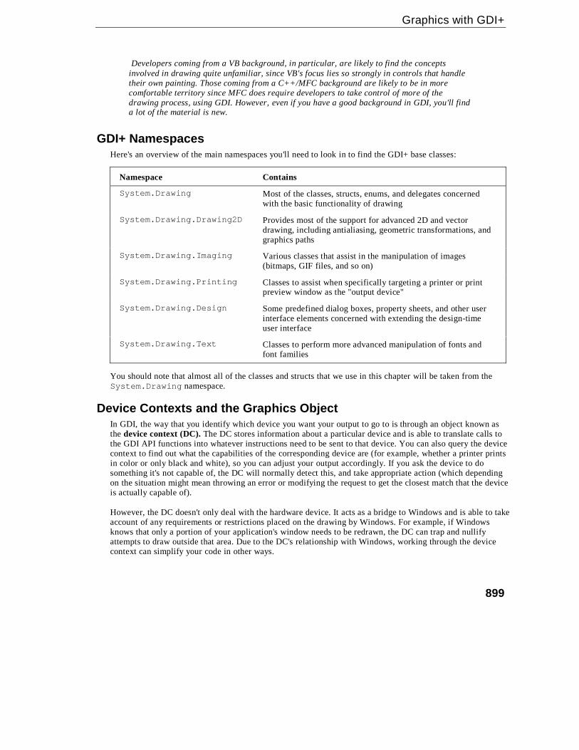
GDI+ NamespacesHere's an overview of the main namespaces you'll need to look in to find the GDI+ base classes:
Namespace Contains
System.Drawing Most of the classes, structs, enums, and delegates concernedwith the basic functionality of drawing
System.Drawing.Drawing2D Provides most of the support for advanced 2D and vectordrawing, including antialiasing, geometric transformations, andgraphics paths
System.Drawing.Imaging Various classes that assist in the manipulation of images(bitmaps, GIF files, and so on)
System.Drawing.Printing Classes to assist when specifically targeting a printer or printpreview window as the "output device"
System.Drawing.Design Some predefined dialog boxes, property sheets, and other userinterface elements concerned with extending the design-timeuser interface
System.Drawing.Text Classes to perform more advanced manipulation of fonts andfont families
You should note that almost all of the classes and structs that we use in this chapter will be taken from theSystem.Drawing namespace.
Device Contexts and the Graphics ObjectIn GDI, the way that you identify which device you want your output to go to is through an object known asthe device context (DC). The DC stores information about a particular device and is able to translate calls tothe GDI API functions into whatever instructions need to be sent to that device. You can also query the devicecontext to find out what the capabilities of the corresponding device are (for example, whether a printer printsin color or only black and white), so you can adjust your output accordingly. If you ask the device to dosomething it's not capable of, the DC will normally detect this, and take appropriate action (which dependingon the situation might mean throwing an error or modifying the request to get the closest match that the deviceis actually capable of).
However, the DC doesn't only deal with the hardware device. It acts as a bridge to Windows and is able to takeaccount of any requirements or restrictions placed on the drawing by Windows. For example, if Windowsknows that only a portion of your application's window needs to be redrawn, the DC can trap and nullifyattempts to draw outside that area. Due to the DC's relationship with Windows, working through the devicecontext can simplify your code in other ways.
Chapter 19
900
For example, hardware devices need to be told where to draw objects, and they usually want coordinatesrelative to the top left corner of the screen (or output device). Usually, however, your application will bethinking of drawing something at a certain position within the client area (the area reserved for drawing) of itsown window, possibly using its own coordinate system. Since the window might be positioned anywhere onthe screen, and a user might move it at any time, translating between the two coordinate systems is potentiallya difficult task. However, the DC always knows where your window is and is able to perform this translationautomatically.
With GDI+, the device context is wrapped up in the .NET base class System.Drawing.Graphics. Mostdrawing is done by calling methods on an instance of Graphics. In fact, since the Graphics class is theclass that is responsible for actually handling most drawing operations, very little gets done in GDI+ thatdoesn't involve a Graphics instance somewhere, so understanding how to manipulate this object is the key tounderstanding how to draw to display devices with GDI+.
Drawing ShapesWe're going to start off with a short example, DisplayAtStartup, to illustrate drawing to an application'smain window. The examples in this chapter are all created in Visual Studio.NET as C# Windows applications.Recall that for this type of project the code wizard gives us a class called Form1, derived fromSystem.Windows.Form, which represents the application's main window. Unless otherwise stated, in allcode samples, new or modified code means code that we've added to the wizard-generated code.
In .NET usage, when we are talking about applications that display various controls, theterminology form has largely replaced window to represent the rectangular object thatoccupies an area of the screen on behalf of an application. In this chapter, we've tended tostick to the term window, since in the context of manually drawing items it's rather moremeaningful. We'll also talk about the Form when we're referring to the .NET class used toinstantiate the form/window. Finally, we'll use the terms drawing and painting interchangeablyto describe the process of displaying some item on the screen or other display device.
The first example will simply create a form and draw to it in the constructor, when the form starts up. I shouldsay at the start that this is not actually the best or the correct way to draw to the screen – we'll quickly find thatthis example has a problem in that it is unable to redraw anything when it needs to after starting up. Howeverthe sample will illustrate quite a few points about drawing without our having to do very much work.
For this sample, we start Visual Studio .NET and create a Windows application. We first set the backgroundcolor of the form to white. We've put this line in the InitializeComponent() method so that VisualStudio .NET recognizes the line and is able to alter the design view appearance of the form. We could haveused the design view to set the background color, but this would have resulted in pretty much the same linebeing added automatically:
private void InitializeComponent(){
this.components = new System.ComponentModel.Container();this.Size = new System.Drawing.Size(300,300);this.Text = "Display At Startup";
this.BackColor = Color.White;

Graphics with GDI+
901
Then we add code to the Form1 constructor. We create a Graphics object using the Form'sCreateGraphics() method. This Graphics object contains the Windows DC we need to draw with. Thedevice context created is associated with the display device, and also with this window:
public Form1(){
InitializeComponent();
Graphics dc = this.CreateGraphics();this.Show();Pen bluePen = new Pen(Color.Blue, 3);dc.DrawRectangle(bluePen, 0,0,50,50);Pen redPen = new Pen(Color.Red, 2);dc.DrawEllipse(redPen, 0, 50, 80, 60);
}
As you can see, we then call the Show() method to display the window. This is really a fudge to force thewindow to display immediately, because we can't actually do any drawing until the window has beendisplayed – there's nothing to draw onto.
Finally, we display a rectangle, at coordinates (0,0), and with width and height 50, and an ellipse withcoordinates (0,50) and with width 80 and height 50. Note that coordinates (x,y) means x pixels to the right andy pixels down from the top left corner of the client area of the window – and these are the coordinates of thetop left corner of the shape being displayed:
The overloads that we are using of the DrawRectangle() and DrawEllipse()methods each take fiveparameters. The first parameter of each is an instance of the class System.Drawing.Pen. A Pen is one of anumber of supporting objects to help with drawing – it contains information about how lines are to be drawn.Our first pen says that lines should be blue and with a width of 3 pixels, the second says that lines should bered and have a width of 2 pixels. The final four parameters are coordinates and size. For the rectangle, theyrepresent the (x,y) coordinates of the top left hand corner of the rectangle, and its width and height. For theellipse these numbers represent the same thing, except that we are talking about a hypothetical rectangle thatthe ellipse just fits into, rather than the ellipse itself.
Running this code gives this result:

Chapter 19
902
I know – the book's printed in grayscale. As with all the screenshots in this chapter, you'll just have to take myword for it that the colors are correct. Or you can always try running the examples yourself!
This screenshot demonstrates a couple of points. First, you can see clearly what the client area of the window means.It's the white area – the area that has been affected by our setting the BackColor property. And notice that therectangle nestles up in the corner of this area, as you'd expect when we specified coordinates of (0,0) for it. Second,notice how the top of the ellipse overlaps the rectangle slightly, which you wouldn't expect from the coordinates wegave in the code. That results from where Windows places the lines that border the rectangle and ellipse. By default,Windows will try to center the line on where the border of the shape is – that's not always possible to do exactly,because the line has to be drawn on pixels (obviously), but normally the border of each shape theoretically liesbetween two pixels. The result is that lines that are 1 pixel thick will get drawn just inside the top and left sides of ashape, but just outside the bottom and right sides – which means that shapes that strictly speaking are next to eachother will have their borders overlap by one pixel. We've specified wider lines; therefore the overlap is greater. It ispossible to change the default behavior by setting the Pen.Alignment property, as detailed in the MSDNdocumentation, but for our purposes the default behavior is adequate.
Unfortunately, if you actually run the sample you'll notice the form behaves a bit strangely. It's fine if you justleave it there, and it's fine if you drag it around the screen with the mouse. Try minimizing it then restoring it,however, and our carefully drawn shapes just vanish! The same thing happens if you drag another windowacross the sample. If you drag another window across it so that it only obscures a portion of our shapes, thendrag the other window away again, you'll find the temporarily obscured portion has disappeared and you're leftwith half an ellipse or half a rectangle!
So what's going on? The problem arises when part of a window gets hidden, because Windows usuallyimmediately discards all the information concerning exactly what was being displayed there. It has to –otherwise the memory usage for storing screen data would be astronomical. A typical computer might berunning with the video card set to display 1024 x 768 pixels, perhaps with 24-bit color mode. We'll cover what24-bit color means later in the chapter, but for now I'll say that implies that each pixel on the screen occupies3 bytes. That means 2.25MB to display the screen. However, it's not uncommon for a user to sit there working,with 10 or 20 minimized windows in the taskbar. Let's do a worst-case scenario: 20 windows, each of whichwould occupy the whole screen if it wasn't minimized. If Windows actually stored the visual information thosewindows contained, ready for when the user restored them, you'd be talking about 45MB! These days, a goodgraphics card might have 64MB of memory and be able to cope with that, but it's only a couple of years agothat 4MB was considered generous in a graphics card – and the excess would need to be stored in thecomputer's main memory. A lot of people still have old machines – for example, my backup computer that hasa 4 MB graphics card. Clearly it wouldn't be practical for Windows to manage its user interface like that.
The moment any part of a window gets hidden, the 'hidden' pixels get lost, because Windows frees thememory that was holding those pixels. It does, however, note that a portion of the window is hidden, and whenit detects that it is no longer hidden, it asks the application that owns the window to redraw its contents. Thereare a couple of exceptions to this rule – generally for cases in which a small portion of a window is hiddenvery temporarily (a good example is when you select an item from the main menu and that menu item dropsdown, temporarily obscuring part of the window below). In general, however, you can expect that if part ofyour window gets hidden, your application will need to redraw it later.
That's the source of the problem for our sample application. We placed our drawing code in the Form1constructor, which is called just once when the application starts up, and you can't call the constructor again toredraw the shapes when required later on.

Graphics with GDI+
903
In Chapter 7, when we covered controls, we didn't need to know about any of that. This is because thestandard controls are pretty sophisticated and they are able to redraw themselves correctly whenever Windowsasks them to. That's one reason why when programming controls you don't need to worry about the actualdrawing process at all. If we are taking responsibility for drawing to the screen in our application then we alsoneed to make sure our application will respond correctly whenever Windows asks it to redraw all or part of itswindow. In the next section, we will modify our sample to do just that.
Painting Shapes Using OnPaint()If the above explanation has made you worried that drawing your own user interface is going to be terriblycomplicated, don't worry. Getting your application to redraw itself when necessary is actually quite easy.
Windows notifies an application that some repainting needs to be done by raising a Paint event.Interestingly, the Form class has already implemented a handler for this event so you don't need to add oneyourself. The Form1 handler for the Paint event will at some point in its processing call up a virtual method,OnPaint(), passing to it a single PaintEventArgs parameter. This means that all we need to do isoverride OnPaint()to perform our painting.
Although we've chosen to work by overriding OnPaint(), it's equally possible to achieve the same results bysimply adding our own event handler for the Paint event (a Form1_Paint() method, say) – in much the sameway as you would for any other Windows Forms event. This other approach is arguably more convenient, since youcan add a new event handler through the VS .NET properties window, saving yourself from typing some code.However, our approach, of overriding OnPaint(), is slightly more flexible in terms of letting us control when thecall to the base class window processing occurs, and is the approach recommended in the documentation. Wesuggest you use this approach for consistency.
We'll create a new Windows Application called DrawShapes to do this. As before, we set the background colorto white using the Properties Window. We'll also change the Form's text to 'DrawShapes sample'. Then we addthe following code to the generated code for the Form1 class:
protected override void OnPaint( PaintEventArgs e ){
base.OnPaint(e);Graphics dc = e.Graphics;Pen bluePen = new Pen(Color.Blue, 3);dc.DrawRectangle(bluePen, 0,0,50,50);Pen redPen = new Pen(Color.Red, 2);dc.DrawEllipse(redPen, 0, 50, 80, 60);
}
Notice that OnPaint() is declared as protected, because it is normally used internally within the class, sothere's no reason for any other code outside the class to know about its existence.
PaintEventArgs is a class that is derived from the EventArgs class normally used to pass in informationabout events. PaintEventArgs has two additional properties, of which the more important is a Graphicsinstance, already primed and optimized to paint the required portion of the window. This means that you don'thave to call CreateGraphics() to get a DC in the OnPaint() method – you've already been providedwith one. We'll look at the other additional property soon – it contains more detailed information about whicharea of the window actually needs repainting.

Chapter 19
904
In our implementation of OnPaint(), we first get a reference to the Graphics object fromPaintEventArgs, then we draw our shapes exactly as we did before. At the end we call the base class'sOnPaint() method. This step is important. We've overridden OnPaint() to do our own painting, but it'spossible that Windows may have some additional work of its own to do in the painting process – any suchwork will be dealt with in an OnPaint() method in one of the .NET base classes.
For this example, you'll find that removing the call to base.OnPaint() doesn't seem to haveany effect, but don't ever be tempted to leave this call out. You might be stopping Windowsfrom doing its work properly and the results could be unpredictable.
OnPaint() will also be called when the application first starts up and our window is displayed for the firsttime, so there is no need to duplicate the drawing code in the constructor.
Running this code gives the same results initially as for our previous example – except that now ourapplication behaves itself properly when you minimize it or hide parts of the window.
Using the Clipping RegionOur DrawShapes sample from the last section illustrates the main principles involved with drawing to awindow, although it's not very efficient. The reason is that it attempts to draw everything in the window,irrespective of how much needs to be drawn. Consider the situation shown in this screenshot. I ran theDrawShapes example, but while it was on the screen I opened another window and moved it over theDrawShapes form, so it hid part of it.
So far, so good. However, when I move the overlapping window so that the DrawShapes window is fullyvisible again, Windows will as usual send a Paint event to the form, asking it to repaint itself. The rectangleand ellipse both lie in the top left corner of the client area, and so were visible all the time; therefore, there'sactually nothing that needs to be done in this case apart from repaint the white background area. However,Windows doesn't know that, so it thinks it should raise the Paint event, resulting in our OnPaint()implementation being called. OnPaint() will then unnecessarily attempt to redraw the rectangle and ellipse.

Graphics with GDI+
905
Actually, in this case, the shapes will not get repainted. The reason is to do with the device context. Windowshas pre-initialized the device context with information concerning what area actually needed repainting. In thedays of GDI, the region that is marked for repainting used to be known as the invalidated region, but withGDI+ the terminology has largely changed to clipping region. The device context knows what this region is;therefore, it will intercept any attempts to draw outside this region, and not pass the relevant drawingcommands on to the graphics card. That sounds good, but there's still a potential performance hit here. Wedon't know how much processing the device context had to do before it figured out that the drawing wasoutside the invalidated region. In some cases it might be quite a lot, since calculating which pixels need to bechanged to what color can be very processor-intensive (although a good graphics card will provide hardwareacceleration to help with some of this).
The bottom line to this is that asking the Graphics instance to do some drawing outside the invalidatedregion is almost certainly wasting processor time and slowing your application down. In a well designedapplication, your code will actively help the device context out by carrying out a few simple checks, to see ifthe proposed drawing work is likely to be actually needed, before it calls the relevant Graphics instancemethods. In this section we're going to code up a new example – DrawShapesWithClipping – bymodifying the DisplayShapes example to do just that. In our OnPaint() code, we'll do a simple test tosee whether the invalidated region intersects the area we need to draw in, and only call the drawing methods ifit does.
First, we need to obtain the details of the clipping region. This is where an extra property, ClipRectangle,on the PaintEventArgs comes in. ClipRectangle contains the coordinates of the region to be repainted,wrapped up in an instance of a struct, System.Drawing.Rectangle. Rectangle is quite a simple struct– it contains four properties of interest: Top, Bottom, Left, and Right. These respectively contain thevertical coordinates of the top and bottom of the rectangle, and the horizontal coordinates of the left and rightedges.
Next, we need to decide what test we'll use to determine whether drawing should take place. We'll go for asimple test here. Notice, that in our drawing, the rectangle and ellipse are both entirely contained within therectangle that stretches from point (0,0) to point (80,130) of the client area; actually, point (82,132) to be onthe safe side, since we know that the lines may stray a pixel or so outside this area. So we'll check whether thetop left corner of the clipping region is inside this rectangle. If it is, we'll go ahead and redraw. If it isn't, wewon't bother.
Here is the code to do this:
protected override void OnPaint( PaintEventArgs e ){
base.OnPaint(e);Graphics dc = e.Graphics;
if (e.ClipRectangle.Top < 132 && e.ClipRectangle.Left < 82){
Pen bluePen = new Pen(Color.Blue, 3);dc.DrawRectangle(bluePen, 0,0,50,50);Pen redPen = new Pen(Color.Red, 2);dc.DrawEllipse(redPen, 0, 50, 80, 60);
}}

Chapter 19
906
Note that what gets displayed is exactly the same as before – but performance is improved now by the earlydetection of some cases in which nothing needs to be drawn. Notice, also that we've chosen a fairly crude testof whether to proceed with the drawing. A more refined test might be to check separately, whether therectangle needs to be drawn, or whether the ellipse needs to be redrawn, or both. However, there's a balancehere. You can make your tests in OnPaint() more sophisticated, improving performance, but you'll alsomake your own OnPaint() code more complex. It's almost always worth putting some test in, becauseyou've written the code so you understand far more about what is being drawn than the Graphics instance,which just blindly follows drawing commands.
Measuring Coordinates and AreasIn our last example, we encountered the base struct, Rectangle, which is used to represent the coordinates ofa rectangle. GDI+ actually uses several similar structures to represent coordinates or areas, and we're at aconvenient point in the chapter to go over the main ones. We'll look at the following structs, which are alldefined in the System.Drawing namespace:
Struct Main Public Properties
struct Point
struct PointFX, Y
struct Size
struct SizeFWidth, Height
struct Rectangle
struct RectangleFLeft, Right, Top, Bottom, Width, Height, X, Y, Location, Size
Note that many of these objects have a number of other properties, methods, or operator overloads not listedhere. In this section we'll just discuss the most important ones.
Point and PointFWe'll look at Point first. Point is conceptually the simplest of these structs. Mathematically, it's completelyequivalent to a 2D vector. It contains two public integer properties, which represent how far you movehorizontally and vertically from a particular location (perhaps on the screen). In other words, look at thisdiagram:
Point A 20 units
Point B
10 units
X
Y

Graphics with GDI+
907
In order to get from point A to point B, you move 20 units across and 10 units down, marked as x and y on thediagram as this is how they are commonly referred to. We could create a Point struct that represents that asfollows:
Point ab = new Point(20, 10);Console.WriteLine("Moved {0} across, {1} down", ab.X, ab.Y);
X and Y are read-write properties, which means you can also set the values in a Point like this:
Point ab = new Point();ab.X = 20;ab.Y = 10;Console.WriteLine("Moved {0} across, {1} down", ab.X, ab.Y);
Note that although conventionally horizontal and vertical coordinates are referred to as x and y coordinates(lowercase), the corresponding Point properties are X and Y (uppercase) because the usual convention in C#is for public properties to have names that start with an uppercase letter.
PointF is essentially identical to Point, except that X and Y are of type float instead of int. PointF isused when the coordinates are not necessarily integer values. A cast has been defined so that you canimplicitly convert from Point to PointF. (Note that because Point and PointF are structs, this castinvolves actually making a copy of the data). There is no corresponding reverse case – to convert fromPointF to Point you have to explicitly copy the values across, or use one of three conversion methods,Round(), Truncate(), and Ceiling():
PointF abFloat = new PointF(20.5F, 10.9F);// converting to PointPoint ab = new Point();ab.X = (int)abFloat.X;ab.Y = (int)abFloat.Y;Point ab1 = Point.Round(abFloat);Point ab2 = Point.Truncate(abFloat);Point ab3 = Point.Ceiling(abFloat);
// but conversion back to PointF is implicitPointF abFloat2 = ab;
You may be wondering what a "unit" is measured in. By default, GDI+ will interpret units as pixels along thescreen (or printer, whatever the graphics device is) – so that's how the Graphics object methods will viewany coordinates that they get passed as parameters. For example, the point new Point(20,10) represents20 pixels across the screen and 10 pixels down. Usually these pixels will be measured from the top left cornerof the client area of the window, as has been the case in our examples up to now. However, that won't alwaysbe the case – for example, on some occasions you may wish to draw relative to the top left corner of the wholewindow (including its border), or even to the top left corner of the screen. In most cases, however, unless thedocumentation tells you otherwise, you can assume you're talking pixels relative to the top left corner of theclient area.
We'll have more to say on this subject later on, after we've examined scrolling, when we mention the threedifferent coordinate systems in use, world, page, and device coordinates.

Chapter 19
908
Size and SizeFLike Point and PointF, sizes come in two varieties. The Size struct is for when you are using ints;SizeF is available if you need to use floats. Otherwise Size and SizeF are identical. We'll focus on theSize struct here.
In many ways the Size struct is identical to the Point struct. It has two integer properties that represent adistance horizontally and a distance vertically – the main difference is that instead of X and Y, these propertiesare named Width and Height. We can represent our earlier diagram by:
Size ab = new Size(20,10);Console.WriteLine("Moved {0} across, {1} down", ab.Width, ab.Height);
Although strictly speaking, a Size mathematically represents exactly the same thing as a Point;conceptually it is intended to be used in a slightly different way. A Point is used when we are talking aboutwhere something is, and a Size is used when we are talking about how big it is. However, because Size andPoint are so closely related, there are even supported explicit conversions between these two:
Point point = new Point(20, 10);Size size = (Size) point;Point anotherPoint = (Point) size;
As an example, think about the rectangle we drew earlier, with top left coordinate (0,0) and size (50,50). Thesize of this rectangle is (50,50) and might be represented by a Size instance. The bottom right corner is alsoat (50,50), but that would be represented by a Point instance. To see the difference, suppose we drew therectangle in a different location, so it's top left coordinate was at (10,10):
dc.DrawRectangle(bluePen, 10,10,50,50);
Now the bottom right corner is at coordinate (60,60), but the size is unchanged – that's still (50,50).
The addition operator has been overloaded for Points and Sizes, so that it is possible to add a Size to aPoint giving another Point:
static void Main(string[] args){
Point topLeft = new Point(10,10);Size rectangleSize = new Size(50,50);Point bottomRight = topLeft + rectangleSize;Console.WriteLine("topLeft = " + topLeft);Console.WriteLine("bottomRight = " + bottomRight);Console.WriteLine("Size = " + rectangleSize);
}
This code, running as a simple console application, called PointsAndSizes, produces this output:

Graphics with GDI+
909
Notice that this output also shows how the ToString() method has been overridden in both Point andSize to display the value in {X,Y} format.
It is also possible to subtract a Size from a Point to give a Point, and you can add two Sizes together,giving another Size. It is not possible, however, to add a Point to another Point. Microsoft decided thatadding Points doesn't conceptually make sense, and so chose not to supply any overload to the + operatorthat would have allowed that.
You can also explicitly cast a Point to a Size and vice versa:
Point topLeft = new Point(10,10);Size s1 = (Size)topLeft;Point p1 = (Point)s1;
With this cast s1.Width is assigned the value of topLeft.X, and s1.Height is assigned the value oftopLeft.Y. Hence, s1 contains (10,10). p1 will end up storing the same values as topLeft.
Rectangle and RectangleFThese structures represent a rectangular region (usually of the screen). Just as with Point and Size, we'llonly consider the Rectangle struct here. RectangleF is basically identical except that those of itsproperties that represent dimensions all use float, whereas those of Rectangle use int.
A Rectangle can be thought of as composed of a point, representing the top left corner of the rectangle, anda Size, which represents how large it is. One of its constructors actually takes a Point and a Size as itsparameters. We can see this by rewriting our earlier code from the DrawShapes sample that draws arectangle:
Graphics dc = e.Graphics;Pen bluePen = new Pen(Color.Blue, 3);Point topLeft = new Point(0,0);Size howBig = new Size(50,50);Rectangle rectangleArea = new Rectangle(topLeft, howBig);dc.DrawRectangle(bluePen, rectangleArea);
This code also uses an alternative override of Graphics.DrawRectangle(), which takes a Pen and aRectangle struct as its parameters.
You can also construct a Rectangle by supplying the top left horizontal coordinate, top left verticalcoordinate, width, and height separately, and in that order, as individual numbers:
Rectangle rectangleArea = new Rectangle(0, 0, 50, 50)
Chapter 19
910
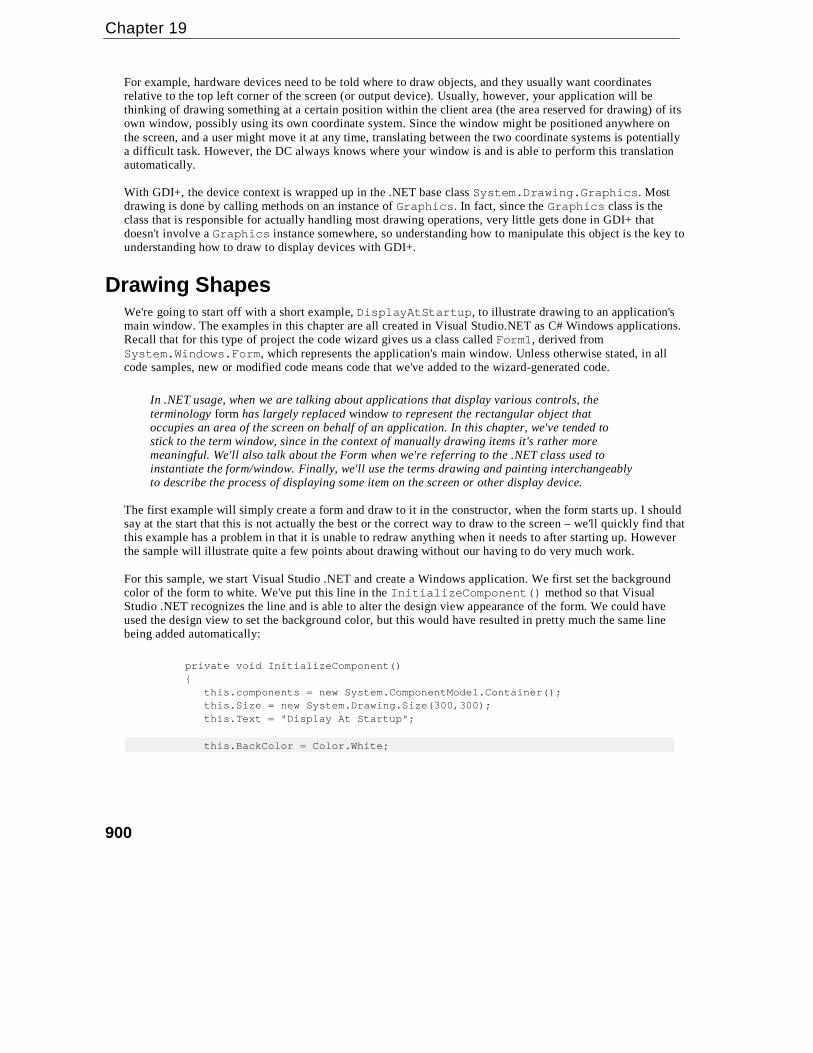
Rectangle makes quite a few read-write properties available to set or extract its dimensions in differentcombinations:
Property Description
int Left x-coordinate of left-hand edge
int Right x-coordinate of right-hand edge
int Top y-coordinate of top
int Bottom y-coordinate of bottom
int X same as Left
int Y same as Top
int Width width of rectangle
int Height height of rectangle
Point Location top left corner
Size Size size of rectangle
Note that these properties are not all independent – for example setting Width will also affect thevalue of Right.
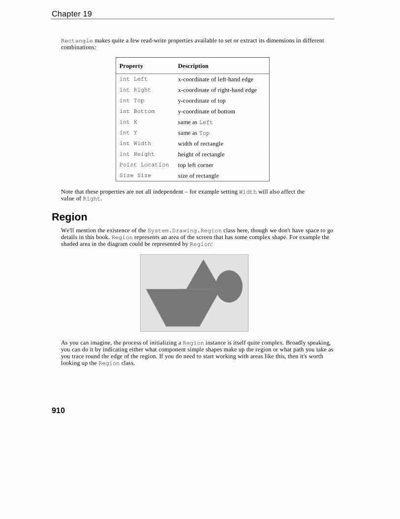
RegionWe'll mention the existence of the System.Drawing.Region class here, though we don't have space to godetails in this book. Region represents an area of the screen that has some complex shape. For example theshaded area in the diagram could be represented by Region:
As you can imagine, the process of initializing a Region instance is itself quite complex. Broadly speaking,you can do it by indicating either what component simple shapes make up the region or what path you take asyou trace round the edge of the region. If you do need to start working with areas like this, then it's worthlooking up the Region class.

Graphics with GDI+
911
A Note about DebuggingWe're just about ready to do some more advanced drawing now. First,however, I just want to say a few thingsabout debugging. If you have a go at setting break points in the examples in this chapter you will quicklynotice that debugging drawing routines isn't quite as simple as debugging other parts of your program. This isbecause entering and leaving the debugger often causes Paint messages to be sent to your application. Theresult can be that setting a breakpoint in your OnPaint() override simply causes your application to keeppainting itself over and over again, so it's unable to do anything else.
A typical scenario is as follows. You want to find out why your application is displaying somethingincorrectly, so you set a break point in OnPaint(). As expected, the application hits the break point and thedebugger comes in, at which point your developer environment MDI window comes to the foreground. Ifyou're anything like me, you probably have the developer environments set to full screen display so you canmore easily view all the debugging information, which means it always completely hides the application youare debugging.
Moving on, you examine the values of some variables and hopefully find out something useful. Then you hitF5 to tell the application to continue, so that you can go on to see what happens when the application displayssomething else, after it's done some processing. Unfortunately, the first thing that happens is that theapplication comes to the foreground and Windows efficiently detects that the form is visible again andpromptly sends it a Paint event. This means, of course, that your break point gets hit again straight away. Ifthat's what you want fine, but more commonly what you really want is to hit the breakpoint later, when theapplication is drawing something more interesting, perhaps after you've selected some menu option to read ina file or in some other way changed what gets displayed. It looks like you're stuck. Either you don't have abreak point in OnPaint() at all, or your application can never get beyond the point where it's displaying itsinitial startup window.
There are a couple of ways around this problem.
If you have a big screen the easiest way is simply to keep your developer environment window tiled ratherthan maximized and keep it well away from your application window – so your application never gets hiddenin the first place. Unfortunately, in most cases that is not a practical solution, because that would make yourdeveloper environment window too small. An alternative that uses the same principle is to have yourapplication declare itself as the topmost application while you are debugging. You do this by setting a propertyin the Form class, TopMost, which you can easily do in the InitializeComponent() method:
private void InitializeComponent(){
this.TopMost = true;
You can also set this property through the Properties Window in Visual Studio .NET.
Being a TopMost window means your application can never be hidden by other windows (except othertopmost windows). It always remains above other windows even when another application has the focus. Thisis how the Task Manager behaves.

Chapter 19
912
Even with this technique you have to be careful, because you can never quite be certain when Windows mightdecide for some reason to raise a Paint event. If you really want to trap some problem that occurs inOnPaint() for some specific circumstance (for example, the application draws something after you select acertain menu option, and something goes wrong at that point), then the best way to do this is to place somedummy code in OnPaint() that tests some condition, which will only be true in the specifiedcircumstances – and then place the break point inside the if block, like this:
protected override void OnPaint( PaintEventArgs e ){
// Condition() evaluates to true when we want to breakif ( Condition() == true){
int ii = 0; // <-- SET BREAKPOINT HERE!!!}
This is effectively a quick-and-easy way of putting in a conditional break point.
Drawing Scrollable WindowsOur earlier DrawShapes sample worked very well, because everything we needed to draw fitted into theinitial window size. In this section we're going to look at what we need to do if that's not the case.
We shall expand our DrawShapes sample to demonstrate scrolling. To make things a bit more realistic, we'llstart by creating an example, BigShapes, in which we will make the rectangle and ellipse a bit bigger. Also,while we're at it we'll demonstrate how to use the Point, Size, and Rectangle structs by using them toassist in defining the drawing areas. With these changes, the relevant part of the Form1 class looks like this:
// member fieldsprivate Point rectangleTopLeft = new Point(0, 0);private Size rectangleSize = new Size(200,200);private Point ellipseTopLeft = new Point(50, 200);private Size ellipseSize = new Size(200, 150);private Pen bluePen = new Pen(Color.Blue, 3);private Pen redPen = new Pen(Color.Red, 2);
protected override void OnPaint( PaintEventArgs e ){
base.OnPaint(e);Graphics dc = e.Graphics;
if (e.ClipRectangle.Top < 350 || e.ClipRectangle.Left < 250){
Rectangle rectangleArea =new Rectangle (rectangleTopLeft, rectangleSize);
Rectangle ellipseArea =new Rectangle (ellipseTopLeft, ellipseSize);
dc.DrawRectangle(bluePen, rectangleArea);dc.DrawEllipse(redPen, ellipseArea);
}}

Graphics with GDI+
913
Notice, that we've also turned the Pen, Size, and Point objects into member fields – this is more efficient thancreating a new Pen every time we need to draw anything, as we have been doing up to now.
The result of running this example looks like this:
We can see a problem instantly. The shapes don't fit in our 300x300 pixel drawing area.
Normally, if a document is too large to display, an application will add scrollbars to let you scroll the windowand look at a chosen part of it. This is another area in which, with the kind of user interface that we weredealing with in Chapter 7, we'd let the .NET runtime and the base classes handle everything. If your form hasvarious controls attached to it then the Form instance will normally know where these controls are and it willtherefore know if its window becomes so small that scrollbars become necessary. The Form instance will alsoautomatically add the scrollbars for you, and not only that, but it's also able to correctly draw whicheverportion of the screen you've scrolled to. In that case there is nothing you need to explicitly do in your code. Inthis chapter, however, we're taking responsibility for drawing to the screen; therefore, we're going to have tohelp the Form instance out when it comes to scrolling.
In the last paragraph we said "if a document is too large to display". This probably made youthink in terms of something like a Word or Excel document. With drawing applications,however, it's better to think of the document as whatever data the application is manipulatingthat it needs to draw. For our current example, the rectangle and ellipse between themconstitute the document.
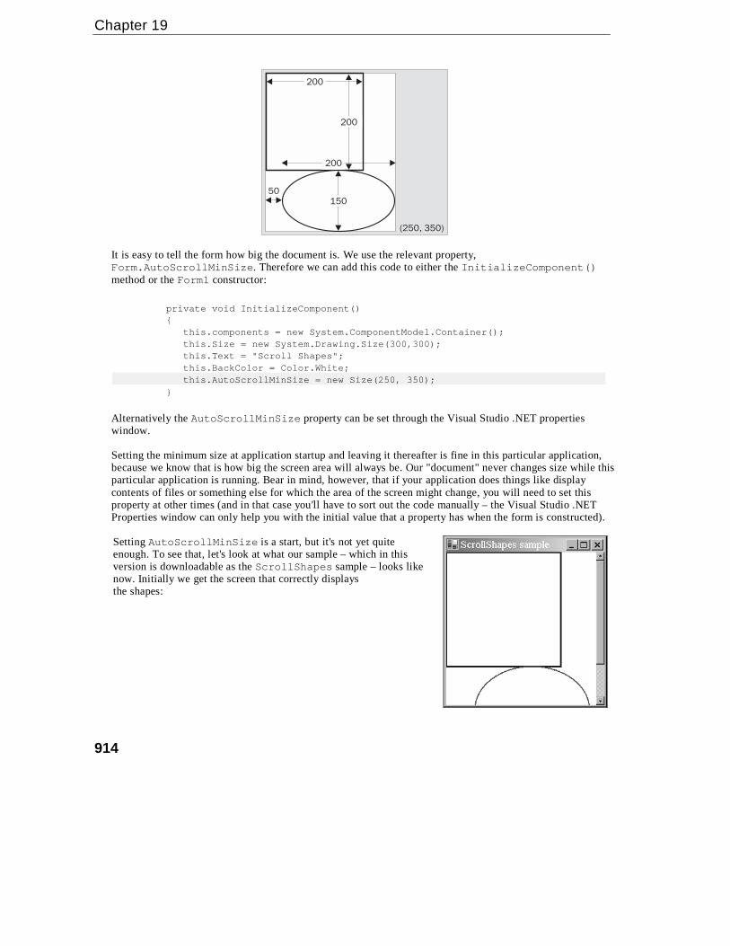
Getting the scrollbars added is actually very easy. The Form can still handle all that for us – the reason it hasn'tin the above ScrollShapes sample is that Windows doesn't know they are needed – because it doesn't knowhow big an area we will want to draw in. How big an area is that? More accurately, what we need to figure outis the size of a rectangle that stretches from the top left corner of the document (or equivalently, the top leftcorner of the client area before we've done any scrolling), and which is just big enough to contain the entiredocument. In this chapter, we'll refer to this area as the document area. Looking at the diagram of the'document' we can see that for this example the document area is (250, 350) pixels.
Chapter 19
914
200
200
200
50150
(250, 350)
It is easy to tell the form how big the document is. We use the relevant property,Form.AutoScrollMinSize. Therefore we can add this code to either the InitializeComponent()method or the Form1 constructor:
private void InitializeComponent(){
this.components = new System.ComponentModel.Container();this.Size = new System.Drawing.Size(300,300);this.Text = "Scroll Shapes";this.BackColor = Color.White;this.AutoScrollMinSize = new Size(250, 350);
}
Alternatively the AutoScrollMinSize property can be set through the Visual Studio .NET propertieswindow.
Setting the minimum size at application startup and leaving it thereafter is fine in this particular application,because we know that is how big the screen area will always be. Our "document" never changes size while thisparticular application is running. Bear in mind, however, that if your application does things like displaycontents of files or something else for which the area of the screen might change, you will need to set thisproperty at other times (and in that case you'll have to sort out the code manually – the Visual Studio .NETProperties window can only help you with the initial value that a property has when the form is constructed).
Setting AutoScrollMinSize is a start, but it's not yet quiteenough. To see that, let's look at what our sample – which in thisversion is downloadable as the ScrollShapes sample – looks likenow. Initially we get the screen that correctly displaysthe shapes:

Graphics with GDI+
915
Notice that, not only has the form correctly set the scrollbars, but it's even correctly sized them to indicatewhat proportion of the document is currently displayed. You can try resizing the window while the sample isrunning – you'll find the scrollbars respond correctly, and even disappear if we make the window big enoughthat they are no longer needed.
However, now look at what happens if we actually use one of the scrollbars and scroll down a bit:
Clearly something has gone wrong!
In fact, what's gone wrong is that we haven't taken into account the position of the scrollbars in the code in ourOnPaint() override. We can see this very clearly if we force the window to completely repaint itself byminimizing and restoring it. The result looks like this:
The shapes have been painted, just as before, with the top left corner of the rectangle nestled into the top leftcorner of the client area – just as if we hadn't moved the scrollbars at all.

Chapter 19
916
Before we go over how to correct this problem, we'll take a closer look at precisely what is happening in thesescreenshots. Doing so is quite instructive, both because it'll help us to understand exactly how the drawing isdone in the presence of scrollbars and because it'll be quite good practice. If you start using GDI+, I promiseyou that sooner or later, you'll find yourself presented with a strange drawing like one of those above, andhaving to try to figure out what has gone wrong.
We'll look at the last screenshot first since that one is easy to deal with. The ScrollShapes sample has justbeen restored so the entire window has just been repainted. Looking back at our code it instructs the graphicsinstance to draw a rectangle with top left coordinates (0,0) – relative to the top left corner of the client area ofthe window – which is what has been drawn. The problem is, that the graphics instance by default interpretscoordinates as relative to the client window – it doesn't know anything about the scrollbars. Our code as yetdoes not attempt to adjust the coordinates for the scrollbar positions. The same goes for the ellipse.
Now, we can tackle the earlier screenshot, from immediately after we'd scrolled down. We notice that here thetop two-thirds or so of the window look fine. That's because these were drawn when the application firststarted up. When you scroll windows, Windows doesn't ask the application to redraw what was already on thescreen. Windows is smart enough to figure out for itself which bits of what's currently being displayed on thescreen can be smoothly moved around to match where the scrollbars now are. That's a much more efficientprocess, since it may be able to use some hardware acceleration to do that too. The bit in this screenshot that'swrong is the bottom third of the window. This part of the window didn't get drawn when the application firstappeared, since before we started scrolling it was outside the client area. This means that Windows asks ourScrollShapes application to draw this area. It'll raise a Paint event passing in just this area as the clippingrectangle. And that's exactly what our OnPaint() override has done.
One way of looking at the problem is that we are at the moment expressing our coordinates relative to the topleft corner of the start of the 'document' – we need to convert them to express them relative to the top leftcorner of the client area instead. The following diagram should make this clear:
P
Document
Client Area(Screen)
B
A
To make the diagram clearer we've actually extended the document further downwards and to the right,beyond the boundaries of the screen, but this doesn't change our reasoning. We've also assumed a smallhorizontal scroll as well as a vertical one.
In the diagram the thin rectangles mark the borders of the screen area and of the entire document. The thicklines mark the rectangle and ellipse that we are trying to draw. P marks some arbitrary point that we aredrawing, which we're going to take as an example. When calling the drawing methods we've supplied thegraphics instance with the vector from point B to (say) point P, expressed as a Point instance. We actuallyneed to give it the vector from point A to point P.

Graphics with GDI+
917
The problem is that we don't know what the vector from A to P is. We know what B to P is – that's just thecoordinates of P relative to the top left corner of the document – the position where we want to draw point P inthe document. We also know what the vector from B to A is – that's just the amount we've scrolled by; this isstored in a property of the Form class called AutoScrollPosition. However, we don't know the vectorfrom A to P.
Now, if you were good at math at school, you might remember what the solution to this is – you just have tosubtract vectors. Say, for example, to get from B to P you move 150 pixels across and 200 pixels down, whileto get from B to A you have to move 10 pixels across and 57 pixels down. That means to get from A to P youhave to move 140 (=150 minus 10) pixels across and 143 (=200 minus 57) pixels down. The Graphics classactually implements a method that will do these calculations for us. It's called TranslateTransform().You pass it the horizontal and vertical coordinates that say where the top left of the client area is relative tothe top left corner of the document, (our AutoScrollPosition property, that is the vector from B to A inthe diagram). Then the Graphics device will from then on work out all its coordinates taking into accountwhere the client area is relative to the document.
After all that explanation, all we need to do is add this line to our drawing code:
dc.TranslateTransform(this.AutoScrollPosition.X, this.AutoScrollPosition.Y);
In fact in our example, it's a little more complicated because we are also separately testing whether we need todo any drawing by looking at the clipping region. We need to adjust this test to take the scroll position intoaccount too. When we've done that, the full drawing code for the sample (downloadable from the Wrox Pressweb site as ScrollShapes) looks like this:
protected override void OnPaint( PaintEventArgs e )
{
base.OnPaint(e);
Graphics dc = e.Graphics;
Size scrollOffset = new Size(this.AutoScrollPosition);
if (e.ClipRectangle.Top+scrollOffset.Width < 350 ||
e.ClipRectangle.Left+scrollOffset.Height < 250)
{
Rectangle rectangleArea = new Rectangle
(rectangleTopLeft+scrollOffset, rectangleSize);
Rectangle ellipseArea = new Rectangle
(ellipseTopLeft+scrollOffset, ellipseSize);
dc.DrawRectangle(bluePen, rectangleArea);
dc.DrawEllipse(redPen, ellipseArea);
}
}
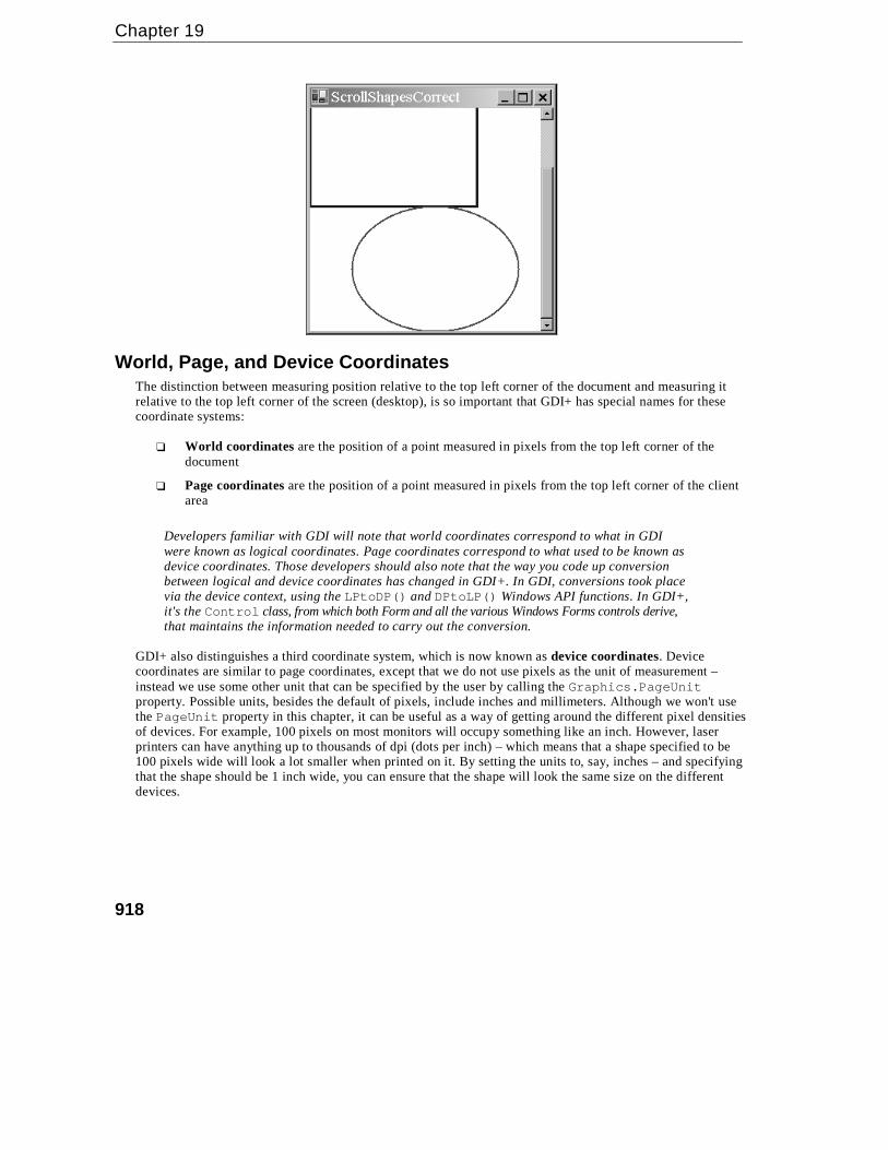
Now we have our scroll code working perfectly, we can at last obtain a correctly scrolled screenshot!
Chapter 19
918
World, Page, and Device CoordinatesThe distinction between measuring position relative to the top left corner of the document and measuring itrelative to the top left corner of the screen (desktop), is so important that GDI+ has special names for thesecoordinate systems:
❑ World coordinates are the position of a point measured in pixels from the top left corner of thedocument
❑ Page coordinates are the position of a point measured in pixels from the top left corner of the clientarea
Developers familiar with GDI will note that world coordinates correspond to what in GDIwere known as logical coordinates. Page coordinates correspond to what used to be known asdevice coordinates. Those developers should also note that the way you code up conversionbetween logical and device coordinates has changed in GDI+. In GDI, conversions took placevia the device context, using the LPtoDP() and DPtoLP() Windows API functions. In GDI+,it's the Control class, from which both Form and all the various Windows Forms controls derive,that maintains the information needed to carry out the conversion.
GDI+ also distinguishes a third coordinate system, which is now known as device coordinates. Devicecoordinates are similar to page coordinates, except that we do not use pixels as the unit of measurement –instead we use some other unit that can be specified by the user by calling the Graphics.PageUnitproperty. Possible units, besides the default of pixels, include inches and millimeters. Although we won't usethe PageUnit property in this chapter, it can be useful as a way of getting around the different pixel densitiesof devices. For example, 100 pixels on most monitors will occupy something like an inch. However, laserprinters can have anything up to thousands of dpi (dots per inch) – which means that a shape specified to be100 pixels wide will look a lot smaller when printed on it. By setting the units to, say, inches – and specifyingthat the shape should be 1 inch wide, you can ensure that the shape will look the same size on the differentdevices.

Graphics with GDI+
919
ColorsIn this section, we're going to look at the ways that you can specify what color you want something to be drawn in.
Colors in GDI+ are represented by instances of the System.Drawing.Color struct. Generally, once you'veinstantiated this struct, you won't do much with the corresponding Color instance – just pass it to whateverother method you are calling that requires a Color. We've encountered this struct before – when we set thebackground color of the client area of the window in each of our samples, as well as when we set the colors ofthe various shapes we were displaying. The Form.BackColor property actually returns a Color instance. Inthis section, we'll look at this struct in more detail. In particular, we'll examine several different ways that youcan construct a Color.
Red-Green-Blue (RGB) ValuesThe total number of colors that can be displayed by a monitor is huge – over 16 million. To be exact thenumber is 2 to the power 24, which works out at 16,777,216. Obviously we need some way of indexing thosecolors so we can indicate which of these is the color we want to display at a given pixel.
The most common way of indexing colors is by dividing them into the red, green, and blue components. Thisidea is based on the principle that any color that the human eye can distinguish can be constructed from acertain amount of red light, a certain amount of the green light, and a certain amount of blue light. Thesecolors are known as components. In practice, it's found that if we divide the amount of each component lightinto 256 possible intensities, then that gives a sufficiently fine gradation to be able to display images that areperceived by the human eye to be of photographic quality. We therefore specify colors by giving the amountsof these components on a scale of 0 to 255 where 0 means that the component is not present and 255 meansthat it is at its maximum intensity.
We can now see where are quoted figure of 16,777,216 colors comes from, since that number is just 256cubed.
This gives us our first way of telling GDI+ about a color. You can indicate a color's red, green, and bluevalues by calling the static function Color.FromArgb(). Microsoft has chosen not to supply a constructorto do this task. The reason is that there are other ways, besides the usual RGB components, to indicate a color.Because of this, Microsoft felt that the meaning of parameters passed to any constructor they defined would beopen to misinterpretation:
Color redColor = Color.FromArgb(255,0,0);
Color funnyOrangyBrownColor = Color.FromArgb(255,155,100);
Color blackColor = Color.FromArgb(0,0,0);
Color whiteColor = Color.FromArgb(255,255,255);
The three parameters are respectively the quantities of red, green, and blue. There are a number of otheroverloads to this function, some of which also allow you to specify something called an alpha-blend (that's theA in the name of the method, FromArgb()). Alpha blending is beyond the scope of this chapter, but it allowsyou to paint a color semi-transparently by combining it with whatever color was already on the screen. Thiscan give some beautiful effects and is often used in games.

Chapter 19
920
The Named ColorsConstructing a Color using FromArgb() is the most flexible technique, since it literally means you can specifyany color that the human eye can see. However, if you want a simple, standard, well-known color such as red orblue, it's a lot easier to just be able to name the color you want. Hence Microsoft has also provided a large number ofstatic properties in Color, each of which returns a named color. It is one of these properties that we used when weset the background color of our windows to white in our samples:
this.BackColor = Color.White;
// has the same effect as:// this.BackColor = Color.FromArgb(255, 255 , 255);
There are several hundred such colors. The full list is given in the MSDN documentation. They include all thesimple colors: Red, White, Blue, Green, Black, and so on, as well as such delights asMediumAquamarine, LightCoral, and DarkOrchid. There is also a KnownColor enumeration, whichlists the named colors.
Incidentally, although it might look that way, these named colors have not been chosen atrandom. Each one represents a precise set of RGB values, and they were originally chosenmany years ago for use on the Internet. The idea was to provide a useful set of colors rightacross the spectrum whose names would be recognized by web browsers – thus saving youfrom having to write explicit RGB values in your HTML code. A few years ago these colorswere also important because early browsers couldn't necessarily display very many colorsaccurately, and the named colors were supposed to provide a set of colors that would bedisplayed correctly by most browsers. These days that aspect is less important since modernweb browsers are quite capable of displaying any RGB value correctly.
Graphics Display Modes and the Safety PaletteAlthough we've said that in principle monitors can display any of the over 16 million RGB colors, in practicethis depends on how you've set the display properties on your computer. In Windows, there are traditionallythree main color options (although some machines may provide other options depending on the hardware):true color (24-bit), high color (16-bit), and 256 colors. (On some graphics cards these days, true color isactually marked as 32-bit for reasons to do with optimizing the hardware, though in that case only 24 bits ofthe 32 bits are used for the color itself.)
Only true-color mode allows you to display all of the RGB colors simultaneously. This sounds the best option,but it comes at a cost: 3 bytes are needed to hold a full RGB value which means 3 bytes of graphics cardmemory are needed to hold each pixel that is displayed. If graphics card memory is at a premium (a restrictionthat's less common now than it used to be) you may choose one of the other modes. High color mode gives you2 bytes per pixel. That's enough to give 5 bits for each RGB component. So instead of 256 gradations of redintensity you just get 32 gradations; the same for blue and green, which gives a total of 65,536 colors. That isjust about enough to give apparent photographic quality on a casual inspection, though areas of subtle shadingtend to be broken up a bit.
256-color mode gives you even fewer colors. However, in this mode, you get to choose which colors. Whathappens is that the system sets up something known as a palette. This is a list of 256 colors chosen from the16 million RGB colors. Once you've specified the colors in the palette, the graphics device will be able todisplay just those colors. The palette can be changed at any time – but the graphics device can still onlydisplay 256 different colors on the screen at any one time. 256-color mode is only really used when highperformance and video memory is at a premium. Most games will use this mode – and they can still achievedecent-looking graphics because of a very careful choice of palette.
Graphics with GDI+
921
In general, if a display device is in high-color or 256-color mode and it is asked to display a particular RGBcolor, it will pick the nearest mathematical match from the pool of colors that it is able to display. It's for thisreason that it's important to be aware of the color modes. If you are drawing something that involves subtleshading or photographic quality images, and the user does not have 24-bit color mode selected, they may notsee the image the same way you intended it. So if you're doing that kind of work with GDI+, you should testyour application in different color modes. (It is also possible for your application to programmatically set agiven color mode, though we won't go into that in this chapter.)
The Safety PaletteFor reference, we'll quickly mention the safety palette, which is a very commonly-used default palette. Theway it works is that we set six equally spaced possible values for each color component. Namely, the values 0,51, 102, 153, 204, and 255. In other words, the red component can have any of these values. So can the greencomponent. So can the blue component. So possible colors from the safety palette include: (0,0,0), black;(153,0,0), a fairly dark shade of red; (0, 255,102), green with a smattering of blue added; and so on. This givesus a total of 6 cubed = 216 colors. The idea is that this gives us an easy way of having a palette that containscolors from right across the spectrum and of all degrees of brightness, although in practice this doesn't actuallywork that well because equal mathematical spacing of color components doesn't mean equal perception ofcolor differences by the human eye. Because the safety palette used to be widely used, however, you'll stillfind a fair number of applications and images exclusively use colors from the safety palette.
If you set Windows to 256-color mode, you'll find the default palette you get is the safety palette, with 20Windows standard colors added to it, and 20 spare colors.
Pens and BrushesIn this section, we'll review two helper classes that are needed in order to draw shapes. We've alreadyencountered the Pen class, used to tell the graphics instance how to draw lines. A related class isSystem.Drawing.Brush, which tells it how to fill regions. For example, the Pen is needed to draw theoutlines of the rectangle and ellipse in our previous samples. If we'd needed to draw these shapes as solid, itwould have been a brush that would have been used to specify how to fill them in. One aspect of both of theseclasses is that you will hardly ever call any methods on them. You simply construct a Pen or Brush instancewith the required color and other properties, and then pass it to drawing methods that require a Pen or Brush.
We will look at brushes first, then pens.
Incidentally, if you've programmed using GDI before you have noticed from the first couple ofexamples that pens are used in a different way in GDI+. In GDI the normal practice was tocall a Windows API function, SelectObject(), which actually associated a pen with thedevice context. That pen was then used in all drawing operations that required a pen until youinformed the device context otherwise, by calling SelectObject()again. The sameprinciple held for brushes and other objects such as fonts or bitmaps. With GDI+, as mentionedearlier, Microsoft has instead gone for a stateless model in which there is no default pen or otherhelper object. Rather, you simply specify with each method call the appropriate helper object to beused for that particular method.
Chapter 19
922
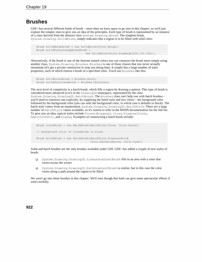
BrushesGDI+ has several different kinds of brush – more than we have space to go into in this chapter, so we'll justexplain the simpler ones to give you an idea of the principles. Each type of brush is represented by an instanceof a class derived from the abstract class System.Drawing.Brush. The simplest brush,System.Drawing.SolidBrush, simply indicates that a region is to be filled with solid color:
Brush solidBeigeBrush = new SolidBrush(Color.Beige);Brush solidFunnyOrangyBrownBrush =
new SolidBrush(Color.FromArgb(255,155,100));
Alternatively, if the brush is one of the Internet named colors you can construct the brush more simply usinganother class, System.Drawing.Brushes. Brushes is one of those classes that you never actuallyinstantiate (it's got a private constructor to stop you doing that). It simply has a large number of staticproperties, each of which returns a brush of a specified color. You'd use Brushes like this:
Brush solidAzureBrush = Brushes.Azure;Brush solidChocolateBrush = Brushes.Chocolate;
The next level of complexity is a hatch brush, which fills a region by drawing a pattern. This type of brush isconsidered more advanced so it's in the Drawing2D namespace, represented by the classSystem.Drawing.Drawing2D.HatchBrush. The Brushes class can't help you with hatch brushes –you'll need to construct one explicitly, by supplying the hatch style and two colors – the foreground colorfollowed by the background color (you can omit the background color, in which case it defaults to black). Thehatch style comes from an enumeration, System.Drawing.Drawing2D.HatchStyle. There are a largenumber of HatchStyle values available, so it's easiest to refer to the MSDN documentation for the full list.To give you an idea, typical styles include ForwardDiagonal, Cross, DiagonalCross,SmallConfetti, and ZigZag. Examples of constructing a hatch brush include:
Brush crossBrush = new HatchBrush(HatchStyle.Cross, Color.Azure);
// background color of CrossBrush is black
Brush brickBrush = new HatchBrush(HatchStyle.DiagonalBrick,Color.DarkGoldenrod, Color.Cyan);
Solid and hatch brushes are the only brushes available under GDI. GDI+ has added a couple of new styles ofbrush:
❑ System.Drawing.Drawing2D.LinearGradientBrush fills in an area with a color thatvaries across the screen
❑ System.Drawing.Drawing2D.PathGradientBrush is similar, but in this case the colorvaries along a path around the region to be filled
We won't go into these brushes in this chapter. We'll note though that both can give some spectacular effects ifused carefully.

Graphics with GDI+
923
PensUnlike brushes, pens are represented by just one class – System.Drawing.Pen. The pen is, however,actually slightly more complex than the brush, because it needs to indicate how thick lines should be (howmany pixels wide) and, for a wide line, how to fill the area inside the line. Pens can also specify a number ofother properties, which are beyond the scope of this chapter, but which include the Alignment property thatwe mentioned earlier, which indicates where in relation to the border of a shape a line should be drawn, aswell as what shape to draw at the end of a line (whether to round off the shape).
The area inside a thick line can be filled with solid color, or it can be filled using a brush. Hence, a Peninstance may contain a reference to a Brush instance. This is quite powerful, as it means you can draw linesthat are colored in by using – say – hatching or linear shading. There are four different ways that you canconstruct a Pen instance that you have designed yourself. You can do it by passing a color, or you can do it bypassing in a brush. Both of these constructors will produce a pen with a width of one pixel. Alternatively, youcan pass in a color or a brush, and additionally a float, which represents the width of the pen. (It needs to bea float in case we are using non-default units such as millimeters or inches for the Graphics object thatwill do the drawing – so we can for example specify fractions of an inch.) So for example, you can constructpens like this:
Brush brickBrush = new HatchBrush(HatchStyle.DiagonalBrick,
Color.DarkGoldenrod, Color.Cyan);
Pen solidBluePen = new Pen(Color.FromArgb(0,0,255));
Pen solidWideBluePen = new Pen(Color.Blue, 4);
Pen brickPen = new Pen(brickBrush);
Pen brickWidePen = new Pen(brickBrush, 10);
Additionally, for the quick construction of pens, you can use the class System.Drawing.Pens which, likethe Brushes class, simply contains a number of stock pens. These pens all have width one pixel and come inthe usual sets of Internet named colors. This allows you to construct pens in this way:
Pen solidYellowPen = Pens.Yellow;
Drawing Shapes and LinesWe've almost finished the first part of the chapter, in which we've covered all the basic classes and objectsrequired in order to draw specified shapes and so on to the screen. We'll round off by reviewing some of thedrawing methods the Graphics class makes available, and presenting a short example that illustrates the useof several brushes and pens.
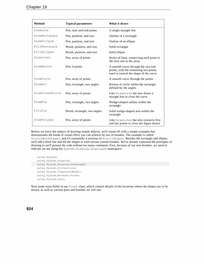
System.Drawing.Graphics has a large number of methods that allow you to draw various lines, outlineshapes, and solid shapes. Once again there are too many to provide a comprehensive list here, but thefollowing table gives the main ones and should give you some idea of the variety of shapes you can draw.
Chapter 19
924
Method Typical parameters What it draws
DrawLine Pen, start and end points A single straight line
DrawRectangle Pen, position, and size Outline of a rectangle
DrawEllipse Pen, position, and size Outline of an ellipse
FillRectangle Brush, position, and size Solid rectangle
FillEllipse Brush, position, and size Solid ellipse
DrawLines Pen, array of points Series of lines, connecting each point tothe next one in the array
DrawBezier Pen, 4 points A smooth curve through the two endpoints, with the remaining two pointsused to control the shape of the curve
DrawCurve Pen, array of points A smooth curve through the points
DrawArc Pen, rectangle, two angles Portion of circle within the rectangledefined by the angles
DrawClosedCurve Pen, array of points Like DrawCurve but also draws astraight line to close the curve
DrawPie Pen, rectangle, two angles Wedge-shaped outline within therectangle
FillPie Brush, rectangle, two angles Solid wedge-shaped area within therectangle
DrawPolygon Pen, array of points Like DrawLines but also connects firstand last points to close the figure drawn
Before we leave the subject of drawing simple objects, we'll round off with a simple example thatdemonstrates the kinds of visual effect you can achieve by use of brushes. The example is calledScrollMoreShapes, and it's essentially a revision of ScrollShapes. Besides the rectangle and ellipse,we'll add a thick line and fill the shapes in with various custom brushes. We've already explained the principles ofdrawing so we'll present the code without too many comments. First, because of our new brushes, we need toindicate we are using the System.Drawing.Drawing2D namespace:
using System;
using System.Drawing;
using System.Drawing.Drawing2D;
using System.Collections;
using System.ComponentModel;
using System.Windows.Forms;
using System.Data;
Next some extra fields in our Form1 class, which contain details of the locations where the shapes are to bedrawn, as well as various pens and brushes we will use:

Graphics with GDI+
925
private Rectangle rectangleBounds = new Rectangle(new Point(0,0),new Size(200,200));
private Rectangle ellipseBounds = new Rectangle(new Point(50,200),new Size(200,150));
private Pen bluePen = new Pen(Color.Blue, 3);private Pen redPen = new Pen(Color.Red, 2);private Brush solidAzureBrush = Brushes.Azure;private Brush solidYellowBrush = new SolidBrush(Color.Yellow);static private Brush brickBrush = new HatchBrush(HatchStyle.DiagonalBrick,
Color.DarkGoldenrod, Color.Cyan);private Pen brickWidePen = new Pen(brickBrush, 10);
The brickBrush field has been declared as static, so that we can use its value to initialize thebrickWidePen field. C# won't let us use one instance field to initialize another instance field, because it'snot defined which one will be initialized first, but declaring the field as static solves the problem. Since onlyone instance of the Form1 class will be instantiated, it is immaterial whether the fields are static or instancefields.
Here is the OnPaint() override:
protected override void OnPaint( PaintEventArgs e ){
base.OnPaint(e);Graphics dc = e.Graphics;Point scrollOffset = this.AutoScrollPosition;dc.TranslateTransform(scrollOffset.X, scrollOffset.Y);if (e.ClipRectangle.Top+scrollOffset.X < 350 ||
e.ClipRectangle.Left+scrollOffset.Y < 250){
dc.DrawRectangle(bluePen, rectangleBounds);dc.FillRectangle(solidYellowBrush, rectangleBounds);dc.DrawEllipse(redPen, ellipseBounds);dc.FillEllipse(solidAzureBrush, ellipseBounds);dc.DrawLine(brickWidePen, rectangleBounds.Location,
ellipseBounds.Location+ellipseBounds.Size);}
}
As before we also set the AutoScrollMinSize to (250,350).Now the results:
Notice that the thick diagonal line has been drawn on top of the rectangle and ellipse, because it was the lastitem to be painted.

Chapter 19
926
Displaying ImagesOne of the most common things you may want to do with GDI+ is display an image that already exists in afile. This is actually a lot simpler than drawing your own user interface, because the image is already pre-drawn. Effectively, all you have to do is load the file and instruct GDI+ to display it. The image can be asimple line drawing, an icon, or a complex image such as a photograph. It's also possible to perform somemanipulations on the image, such as stretching it or rotating it, and you can choose to display only a portion ofit.
In this section, just for a change, we'll present the sample first. Then we'll discuss some of the issues you needto be aware of when displaying images. We can do this, because the code needed to display an image really isso simple.
The class we need is the .NET base class, System.Drawing.Image. An instance of Image represents oneimage – if you like, one picture. Reading in an image takes one line of code:
Image myImage = Image.FromFile("FileName");
FromFile() is a static member of Image and is the usual way of instantiating an image. The file can be anyof the commonly-supported graphics file formats, including .bmp, .jpg, .gif, and .png.
Displaying an image is also very simple, assuming you have a suitable Graphics instance to hand – a simplecall to either Graphics.DrawImageUnscaled() or Graphics.DrawImage() will suffice. There arequite a few overloads of these methods, allowing you a lot of flexibility in the information you supply in termsof where the image is located and how big it is to be drawn. But we will use DrawImage(), like this:
dc.DrawImage(myImage, points);
In this line of code, dc is assumed to be a Graphics instance, while myImage is the Image to be displayed.points is an array of Point structs, where points[0], points[1], and points[2] are the coordinatesof top left, top right, and bottom left corner of the image.
Images are probably the area in which developers familiar with GDI will notice the biggestdifference with GDI+. In GDI, displaying an image involved several nontrivial steps. If theimage was a bitmap, loading it was reasonably simple, but if it was any other file type, loadingit would involve a sequence of calls to OLE objects. Actually getting a loaded image onto thescreen involved getting a handle to it, selecting it into a memory device context, thenperforming a block transfer between device contexts. Although the device contexts and handlesare still there behind the scenes, and will be needed if you want to start doing sophisticatedediting of the images from your code, simple tasks have now been extremely well wrapped upin the GDI+ object model.
We'll illustrate the process of displaying an image with an example called DisplayImage. The examplesimply displays a .jpg file in the application's main window. To keep things simple, the path of the .jpg fileis hard coded into the application (so if you run the example you'll need to change it to reflect the location ofthe file in your system). The .jpg file we'll display is a group photograph of attendees from a recentCOMFest event.

Graphics with GDI+
927
COMFest (www.comfest.co.uk) is an informal group of developers in the UK who meet todiscuss the latest technologies and swap ideas. The picture includes all the attendees atCOMFest 4, except for the author of this chapter who was (conveniently) taking the picture!
As usual for this chapter, the DisplayImage project is a standard C# Visual Studio .NET-generatedWindows application. We add the following fields to our Form1 class:
Image piccy;private Point [] piccyBounds;
We then load the file in the Form1() constructor:
public Form1(){
InitializeComponent();
piccy =Image.FromFile(@"C:\ProCSharp\GdiPlus\Images\CF4Group.bmp");
this.AutoScrollMinSize = piccy.Size;piccyBounds = new Point[3];piccyBounds[0] = new Point(0,0); // top leftpiccyBounds[1] = new Point(piccy.Width,0); // top rightpiccyBounds[2] = new Point(0,piccy.Height); // bottom left
}
Note that the size in pixels of the image is obtained as its Size property, which we use to set the documentarea. We also set up the piccyBounds array, which is used to identify the position of the image on thescreen. We have chosen the coordinates of the three corners to draw the image in its actual size and shapehere, but if we'd wanted the image to be resized, stretched, or even sheared into a non-rectangularparallelogram, we could do so simply by changing the values of the Points in the piccyBounds array.
The image is displayed in the OnPaint() override:
protected override void OnPaint(PaintEventArgs e){
base.OnPaint(e);Graphics dc = e.Graphics;dc.ScaleTransform(1.0f, 1.0f);dc.TranslateTransform(this.AutoScrollPosition.X, this.AutoScrollPosition.Y);dc.DrawImage(piccy, piccyBounds);
}
Finally, we'll take particular note of the modification made to the code wizard-generated Form1.Dispose()method:
protected override void Dispose(bool disposing){
piccy.Dispose();

Chapter 19
928
if( disposing ){
if (components != null){
components.Dispose();}
}base.Dispose( disposing );
}
Disposing of the image as soon as possible when it's no longer needed is important, because images generallyeat a lot of memory while in use. After Image.Dispose() has been called the Image instance no longerrefers to any actual image, and so can no longer be displayed (unless you load a new image).
Running this code produces these results:
Issues When Manipulating ImagesAlthough displaying images is very simple, it still pays to have some understanding what's going on behind the scenes.
The most important point to understand about images is that they are always rectangular. That's not just aconvenience, but because of the underlying technology. It's because all modern graphics cards have hardwarebuilt-in that can very efficiently copy blocks of pixels from one area of memory to another area of memory,provided that the block of pixels represents a rectangular region. This hardware-accelerated operation canoccur virtually as one single operation, and as such is extremely fast. Indeed, it is the key to modern high-performance graphics. This operation is known as a bitmap block transfer (or BitBlt).Graphics.DrawImageUnscaled() internally uses a BitBlt, which is why you can see a huge image,perhaps containing as many as a million pixels, appearing almost instantly. If the computer had to copy theimage to the screen individually pixel by pixel, you'd see the image gradually being drawn over a period of upto several seconds.
BitBlts are very efficient; therefore almost all drawing and manipulation of images is carried out usingthem. Even some editing of images will be done by BitBlting portions of images between DCs that representareas of memory. In the days of GDI, the Windows 32 API function BitBlt() was arguably the mostimportant and widely used function for image manipulation, though with GDI+ the BitBlt operations arelargely hidden by the GDI+ object model.

Graphics with GDI+
929
It's not possible to BitBlt areas of images that are not rectangular, although similar effects can be easilysimulated. One way is to mark a certain color as transparent for the purposes of a BitBlt, so that areas of thatcolor in the source image will not overwrite the existing color of the corresponding pixel in the destinationdevice. It is also possible to specify that in the process of a BitBlt, each pixel of the resultant image will beformed by some logical operation (such as a bitwise AND) on the colors of that pixel in the source image and inthe destination device before the BitBlt. Such operations are supported by hardware acceleration, and can beused to give a variety of subtle effects. We're not going to go into details of this here. We'll remark however,that the Graphics object implements another method, DrawImage(). This is similar toDrawImageUnscaled(), but comes in a large number of overloads that allow you to specify more complexforms of BitBlt to be used in the drawing process. DrawImage() also allows you to draw (BitBlt) only aspecified part of the image, or to perform certain other operations on it such as scaling it (expanding orreducing it in size) as it is drawn.
Drawing TextWe've left the very important topic of displaying text until this late in the chapter because drawing text to thescreen is (in general) more complex than drawing simple graphics. Although displaying a line or two of textwhen you're not that bothered about the appearance is extremely easy – it takes one single call to theGraphics.DrawString() method, if you are trying to display a document that has a fair amount of text init, you rapidly find that things become a lot more complex. This is for two reasons:
❑ If you're concerned about getting the appearance just right, you need to understand fonts. Whereshape drawing requires brushes and pens as helper objects, the process of drawing textcorrespondingly requires fonts as helper objects. And understanding fonts is not trivial task.
❑ Text needs to be very carefully laid out in the window. Users generally expect words to follownaturally from one another – to be lined up with clear spaces in between. Doing that is harder thanyou'd think. For a start, unlike the case for shapes, you don't usually know in advance how muchspace on the screen a word is going to take up. That has to be calculated (using theGraphics.MeasureString() method). Also, how much space on the screen a word occupieswill affect whereabouts on the screen every subsequent word in the document gets placed. If yourapplication does line wrapping then it'll need to carefully assess word sizes before deciding where toplace the break. The next time you run Word for Windows, look carefully at the way Word iscontinually repositioning text as you do your work: there's a lot of complex processing going onthere. The chances are that any GDI+ application you work on won't be anything like as complex asWord, but if you need to display any text then many of the same considerations still apply.
So, good quality text processing is tricky to get right, but putting a line of text on the screen, assuming youknow the font and where you want it to go, is actually very simple. Therefore, the next thing we'll do ispresent a quick example that shows how to display a couple of pieces of text. After that, the plan for the rest ofthe chapter is to review some of the principles of fonts and font families before moving on to our morerealistic text-processing example, the CapsEditor sample, which will demonstrate some of the issuesinvolved when you're trying to control text layout on-screen, and will also show how to handle user input.
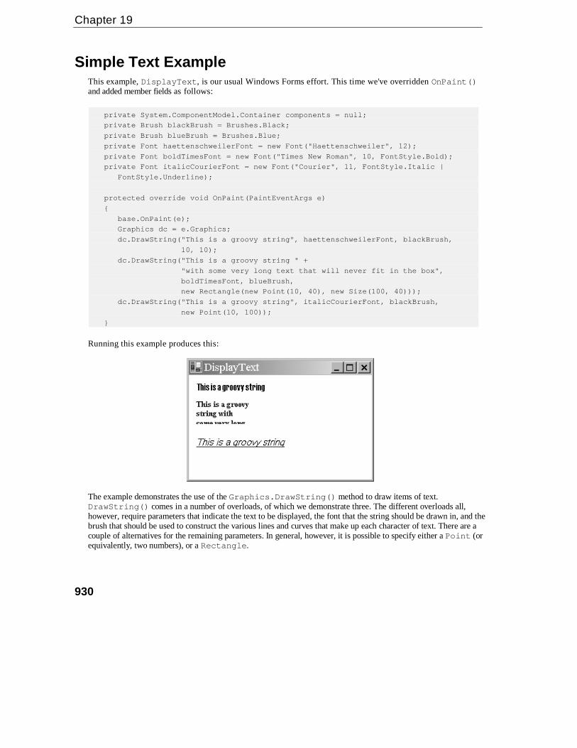
Chapter 19
930
Simple Text ExampleThis example, DisplayText, is our usual Windows Forms effort. This time we've overridden OnPaint()and added member fields as follows:
private System.ComponentModel.Container components = null;
private Brush blackBrush = Brushes.Black;
private Brush blueBrush = Brushes.Blue;
private Font haettenschweilerFont = new Font("Haettenschweiler", 12);
private Font boldTimesFont = new Font("Times New Roman", 10, FontStyle.Bold);
private Font italicCourierFont = new Font("Courier", 11, FontStyle.Italic |
FontStyle.Underline);
protected override void OnPaint(PaintEventArgs e)
{
base.OnPaint(e);
Graphics dc = e.Graphics;
dc.DrawString("This is a groovy string", haettenschweilerFont, blackBrush,
10, 10);
dc.DrawString("This is a groovy string " +
"with some very long text that will never fit in the box",
boldTimesFont, blueBrush,
new Rectangle(new Point(10, 40), new Size(100, 40)));
dc.DrawString("This is a groovy string", italicCourierFont, blackBrush,
new Point(10, 100));
}
Running this example produces this:
The example demonstrates the use of the Graphics.DrawString() method to draw items of text.DrawString() comes in a number of overloads, of which we demonstrate three. The different overloads all,however, require parameters that indicate the text to be displayed, the font that the string should be drawn in, and thebrush that should be used to construct the various lines and curves that make up each character of text. There are acouple of alternatives for the remaining parameters. In general, however, it is possible to specify either a Point (orequivalently, two numbers), or a Rectangle.

Graphics with GDI+
931
If you specify a Point, the text will start with its top left corner at that Point and simply stretch out to theright. If you specify a Rectangle, then the Graphics instance will lay the string out inside that rectangle. Ifthe text doesn't fit into the bounds of the rectangle, then it'll be cut off, as you see from the screenshot. Passinga rectangle to DrawString() means that the drawing process will take longer, as DrawString() will needto figure out where to put line breaks, but the result may look nicer, provided the string fits in the rectangle!
This example also shows a couple of ways of constructing fonts. You always need the name of the font, and its size(height). You can also optionally pass in various styles that modify how the text is to be drawn (bold, underline, and soon).
Fonts and Font FamiliesWe all think intuitively that we have a fairly good understanding of fonts; after all we look at them almost allthe time. A font describes exactly how each letter should be displayed. Selection of the appropriate font andproviding a reasonable variety of fonts within a document are important factors in improving readability.
Oddly, our intuitive understanding usually isn't quite correct. Most people, if asked to name a font, will saythings like 'Arial' or 'Times New Roman' or 'Courier'. In fact, these are not fonts at all – they are font families.The font family tells you in generic terms the visual style of the text, and is a key factor in the overallappearance of your application. Most of us will have become used to recognizing the styles of the mostcommon font families, even if we're not consciously aware of this.
An actual font would be something like Arial 9-point italic. In other words, the size and other modifications tothe text are specified as well as the font family. These modifications might include whether it is bold, italic,underlined, or displayed in SMALL CAPS or as a subscript; this is technically referred to the style, though in someways the term is misleading since the visual appearance is determined as much by the font family.
The way the size of the text is measured is by specifying its height. The height is measured in points – atraditional unit, which represents 1/72 of an inch (0.351 mm). So letters in a 10-point font are roughly 1/7'' or3.5 mm high. However, you won't get seven lines of 10 point text into one inch of vertical screen or paperspace, because you need to allow for the spacing between the lines as well.
Strictly speaking, measuring the height isn't quite as simple as that, since there are severaldifferent heights that you need to consider. For example, there is the height of tall letters likethe A or F (this is the measurement that we really mean when we talk about the height), theadditional height occupied by any accents on letters like Å or Ñ (the internal leading), and theextra height below the base line needed for the tails of letters like y and g (the descent).However, for this chapter we won't worry about that. Once you specify the font family and themain height, these subsidiary heights are determined automatically – you can't independentlychoose their values.
When you're dealing with fonts you may also encounter some other terms that are commonly used to describecertain font families.
❑ A serif font family is one that has little tick marks at the ends of many of the lines that make up thecharacters (These ticks are known as serifs). Times New Roman is a classic example of this.

Chapter 19
932
❑ Sans serif font families, by contrast, don't have these ticks. Good examples of sans serif fonts areArial, and Verdana. The lack of tick marks often gives text a blunt, in-your-face appearance, sosans serif fonts are often used for important text.
❑ A True Type font family is one that is defined by expressing the shapes of the curves that make upthe characters in a precise mathematical manner. This means that that the same definition can beused to calculate how to draw fonts of any size within the family. These days, virtually all the fontsyou will use are true type fonts. Some older font families from the days of Windows 3.1 weredefined by individually specifying the bitmap for each character separately for each font size, butthe use of these fonts is now discouraged.
Microsoft has provided two main classes that we need to deal with when selecting or manipulating fonts.These are:
❑ System.Drawing.Font
❑ System.Drawing.FontFamily
We have already seen the main use of the Font class. When we wish to draw text we instantiate an instance ofFont and pass it to the DrawString() method to indicate how the text should be drawn. A FontFamilyinstance is used (surprisingly enough) to represent a family of fonts.
One use of the FontFamily class is if you know you want a font of a particular type (Serif, Sans Serif orMonospace), but don't mind which font. The static properties GenericSerif, GenericSansSerif, andGenericMonospace return default fonts that satisfy these criteria:
FontFamily sansSerifFont = FontFamily.GenericSansSerif;
Generally speaking, however, if you're writing a professional application, you will want to choose your font ina more sophisticated way than this. Most likely, you will implement your drawing code so that it checks thefont families available, and selects the appropriate one, perhaps by taking the first available one on a list ofpreferred fonts. And if you want your application to be very user-friendly, the first choice on the list willprobably be the one that the user selected last time they ran your software. Usually, if you're dealing with themost popular font families, such as Arial and Times New Roman, you'll be safe. However, if you do try todisplay text using a font that doesn't exist the results aren't always predictable and you're quite likely to findthat Windows just substitutes the standard system font, which is very easy for the system to draw but it doesn'tlook very pleasant – and if it does appear in your document it's likely to give the impression of very poor-quality software.
You can find out what fonts are available on your system using a class called InstalledFontCollection,which is in the System.Drawing.Text namespace. This class implements a property, Families, which isan array of all the fonts that are available to use on your system:
InstalledFontCollection insFont = new InstalledFontCollection();FontFamily [] families = insFont.Families;foreach (FontFamily family in families){
// do processing with this font family
}

Graphics with GDI+
933
Example: Enumerating Font FamiliesIn this section, we will work through a quick example, EnumFontFamilies, which lists all the font familiesavailable on the system and illustrates them by displaying the name of each family using an appropriate font(the 10-point regular version of that font family). When the sample is run it will look something like this:
Of course, the results that you get will depend on what fonts you have installed on your computer.
For this sample we have as usual created a standard C# Windows Application – this time namedEnumFontFamilies. We start off by adding an extra namespace to be searched. We will be using theInstalledFontCollection class, which is defined in System.Drawing.Text.
using System;
using System.Drawing;using System.Drawing.Text;
We then add the following constant to the Form1 class:
private const int margin = 10;
margin will be the size of the left and top margin between the text and the edge of the document – it stops thetext from appearing right at the edge of the client area.
This is designed as a quick-and-easy way of showing off font families; therefore the code is crude and in manycases doesn't do things the way you ought to in a real application. For example, I've just hard-coded in aguessed value for the document size of (200,1500) and set the AutoScrollMinSize property to this valueusing the Visual Studio .NET Properties window. Normally you would have to examine the text to bedisplayed to work out the document size. We will do that in the next section.
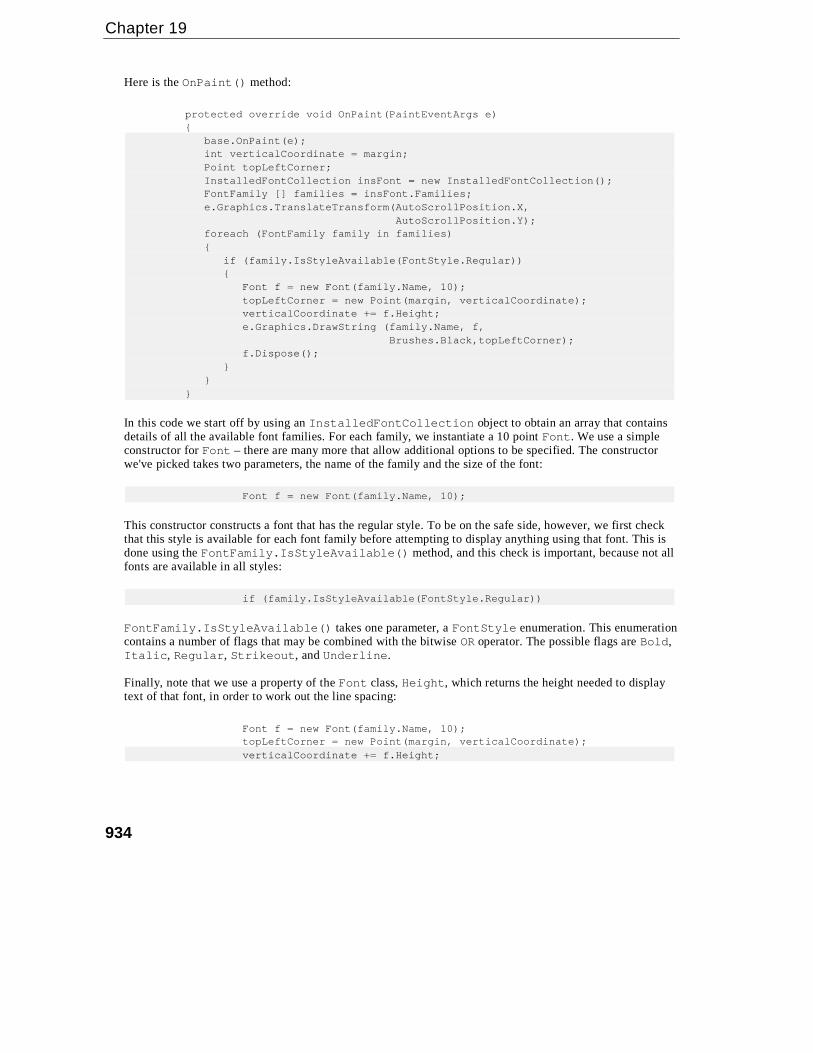
Chapter 19
934
Here is the OnPaint() method:
protected override void OnPaint(PaintEventArgs e){
base.OnPaint(e);int verticalCoordinate = margin;Point topLeftCorner;InstalledFontCollection insFont = new InstalledFontCollection();FontFamily [] families = insFont.Families;e.Graphics.TranslateTransform(AutoScrollPosition.X,
AutoScrollPosition.Y);foreach (FontFamily family in families){
if (family.IsStyleAvailable(FontStyle.Regular)){
Font f = new Font(family.Name, 10);topLeftCorner = new Point(margin, verticalCoordinate);verticalCoordinate += f.Height;e.Graphics.DrawString (family.Name, f,
Brushes.Black,topLeftCorner);f.Dispose();
}}
}
In this code we start off by using an InstalledFontCollection object to obtain an array that containsdetails of all the available font families. For each family, we instantiate a 10 point Font. We use a simpleconstructor for Font – there are many more that allow additional options to be specified. The constructorwe've picked takes two parameters, the name of the family and the size of the font:
Font f = new Font(family.Name, 10);
This constructor constructs a font that has the regular style. To be on the safe side, however, we first checkthat this style is available for each font family before attempting to display anything using that font. This isdone using the FontFamily.IsStyleAvailable() method, and this check is important, because not allfonts are available in all styles:
if (family.IsStyleAvailable(FontStyle.Regular))
FontFamily.IsStyleAvailable() takes one parameter, a FontStyle enumeration. This enumerationcontains a number of flags that may be combined with the bitwise OR operator. The possible flags are Bold,Italic, Regular, Strikeout, and Underline.
Finally, note that we use a property of the Font class, Height, which returns the height needed to displaytext of that font, in order to work out the line spacing:
Font f = new Font(family.Name, 10);topLeftCorner = new Point(margin, verticalCoordinate);verticalCoordinate += f.Height;
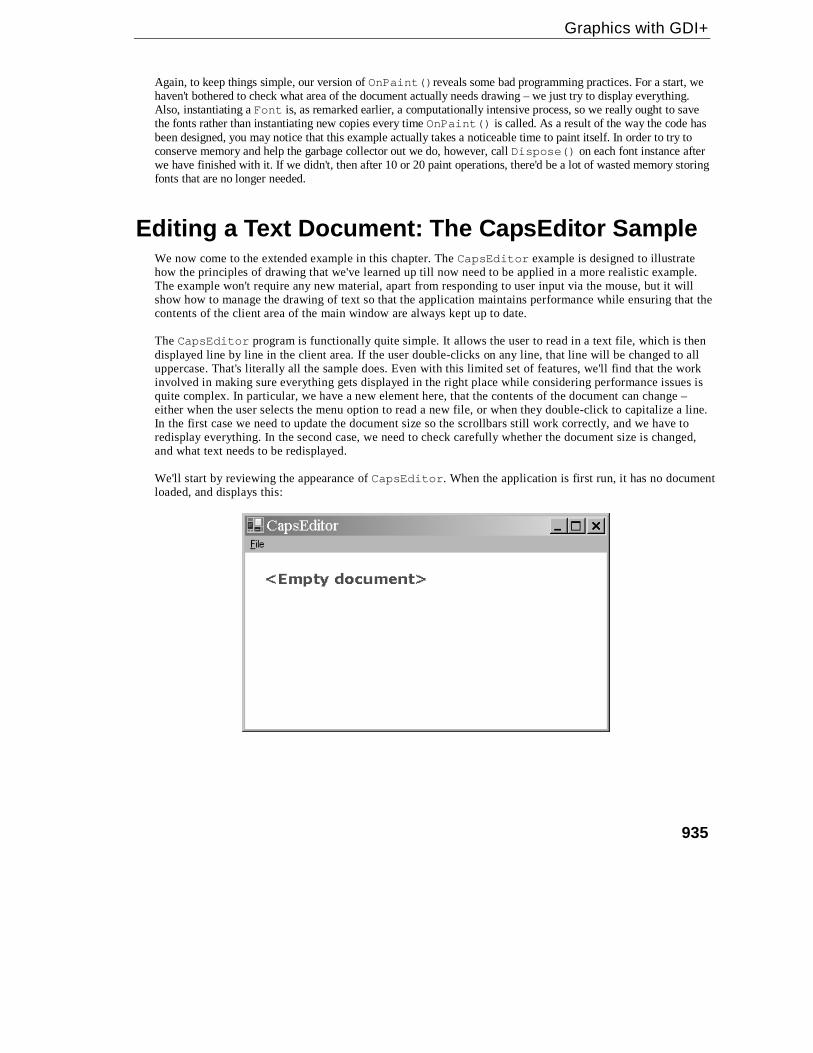
Graphics with GDI+
935
Again, to keep things simple, our version of OnPaint()reveals some bad programming practices. For a start, wehaven't bothered to check what area of the document actually needs drawing – we just try to display everything.Also, instantiating a Font is, as remarked earlier, a computationally intensive process, so we really ought to savethe fonts rather than instantiating new copies every time OnPaint() is called. As a result of the way the code hasbeen designed, you may notice that this example actually takes a noticeable time to paint itself. In order to try toconserve memory and help the garbage collector out we do, however, call Dispose() on each font instance afterwe have finished with it. If we didn't, then after 10 or 20 paint operations, there'd be a lot of wasted memory storingfonts that are no longer needed.
Editing a Text Document: The CapsEditor SampleWe now come to the extended example in this chapter. The CapsEditor example is designed to illustratehow the principles of drawing that we've learned up till now need to be applied in a more realistic example.The example won't require any new material, apart from responding to user input via the mouse, but it willshow how to manage the drawing of text so that the application maintains performance while ensuring that thecontents of the client area of the main window are always kept up to date.
The CapsEditor program is functionally quite simple. It allows the user to read in a text file, which is thendisplayed line by line in the client area. If the user double-clicks on any line, that line will be changed to alluppercase. That's literally all the sample does. Even with this limited set of features, we'll find that the workinvolved in making sure everything gets displayed in the right place while considering performance issues isquite complex. In particular, we have a new element here, that the contents of the document can change –either when the user selects the menu option to read a new file, or when they double-click to capitalize a line.In the first case we need to update the document size so the scrollbars still work correctly, and we have toredisplay everything. In the second case, we need to check carefully whether the document size is changed,and what text needs to be redisplayed.
We'll start by reviewing the appearance of CapsEditor. When the application is first run, it has no documentloaded, and displays this:

Chapter 19
936
The File menu has two options: Open and Exit. Exit exits the application, while Open brings up the standardOpenFileDialog and reads in whatever file the user selects. The next screenshot shows CapsEditorbeing used to view its own source file, Form1.cs. I've also randomly double-clicked on a couple of lines toconvert them to uppercase:
The sizes of the horizontal and vertical scrollbars are, by the way, correct. The client area will scroll justenough to view the entire document. CapsEditor doesn't try to wrap lines of text – the example is alreadycomplicated enough without doing that. It just displays each line of the file exactly as it is read in. There areno limits to the size of the file, but we are assuming it is a text file and doesn't contain any non-printablecharacters.
We'll start off by adding a using command:
using System;using System.Drawing;using System.Collections;using System.ComponentModel;using System.Windows.Forms;using System.Data;using System.IO;
This is because we'll be using the StreamReader class which is in System.IO. Next we'll add in somefields to the Form1 class:
#region Constant fieldsprivate const string standardTitle = "CapsEditor";
// default text in titlebarprivate const uint margin = 10;
// horizontal and vertical margin in client area#endregion
#region Member fieldsprivate ArrayList documentLines = new ArrayList(); // the 'document'

Graphics with GDI+
937
private uint lineHeight; // height in pixels of one lineprivate Size documentSize; // how big a client area is needed to
// display documentprivate uint nLines; // number of lines in documentprivate Font mainFont; // font used to display all linesprivate Font emptyDocumentFont; // font used to display empty messageprivate Brush mainBrush = Brushes.Blue;
// brush used to display document textprivate Brush emptyDocumentBrush = Brushes.Red;
// brush used to display empty document messageprivate Point mouseDoubleClickPosition;
// location mouse is pointing to when double-clickedprivate OpenFileDialog fileOpenDialog = new OpenFileDialog();
// standard open file dialogprivate bool documentHasData = false;
// set to true if document has some data in it#endregion
Most of these fields should be self-explanatory. The documentLines field is an ArrayList that containsthe actual text of the file that has been read in. In a real sense, this is the field that contains the data in the"document". Each element of documentLines contains information for one line of text that has been read in.Since it's an ArrayList, rather than a plain array, we can dynamically add elements to it as we read in a file.You'll notice I've also liberally used #region preprocessor directives to block up bits of the program to makeit easier to edit.
I said each documentLines element contains information about a line of text. This information is actuallyan instance of another class I've defined, TextLineInformation:
class TextLineInformation{
public string Text;public uint Width;
}
TextLineInformation looks like a classic case where you'd normally use a struct rather than a classsince it's just there to group together a couple of fields. However, its instances are always accessed aselements of an ArrayList, which expects its elements to be stored as reference types, so declaringTextLineInformation as a class makes things more efficient by saving a lot of boxing and unboxingoperations.
Each TextLineInformation instance stores a line of text – and that can be thought of as the smallest itemthat is displayed as a single item. In general, for each similar item in a GDI+ application, you'd probably wantto store the text of the item, as well as the world coordinates of where it should be displayed and its size (thepage coordinates will change frequently, whenever the user scrolls, whereas world coordinates will normallyonly change when other parts of the document are modified in some way). In this case we've only stored theWidth of the item. The reason is because the height in this case is just the height of whatever our selectedfont is. It's the same for all lines of text so there's no point storing it separately for each one; we store it once,in the Form1.lineHeight field. As for the position – well in this case the x coordinate is just equal to themargin, and the y coordinate is easily calculated as:
margin + lineHeight*(however many lines are above this one)

Chapter 19
938
If we'd been trying to display and manipulate, say, individual words instead of complete lines, then the xposition of each word would have to be calculated using the widths of all the previous words on that line oftext, but I wanted to keep it simple here, which is why we're treating each line of text as one single item.
Let's deal with the main menu now. This part of the application is more the realm of Windows Forms – thesubject of Chapter 7, than of GDI+. I added the menu options using the design view in Visual Studio .NET,but renamed them as menuFile, menuFileOpen, and menuFileExit. I then added event handlers for theFile Open and File Exit menu options using the Visual Studio .NET Properties window. The event handlershave their VS .NET-generated names of menuFileOpen_Click()and menuFileExit_Click().
We need some extra initialization code in the Form1() constructor:
public Form1(){
InitializeComponent();
CreateFonts();fileOpenDialog.FileOk += new
System.ComponentModel.CancelEventHandler(this.OpenFileDialog_FileOk);fileOpenDialog.Filter =
"Text files (*.txt)|*.txt|C# source files (*.cs)|*.cs";
}
The event handler added here is for when the user clicks OK on the File Open dialog. We have also set thefilter for the open file dialog so that we can only load up text files – we've opted for .txt files as well as C#source files, so we can use the application to examine the sourcecode for our samples.
CreateFonts() is a helper method that sorts out the fonts we intend to use:
private void CreateFonts(){
mainFont = new Font("Arial", 10);lineHeight = (uint)mainFont.Height;emptyDocumentFont = new Font("Verdana", 13, FontStyle.Bold);
}
The actual definitions of the handlers are pretty standard stuff:
protected void OpenFileDialog_FileOk(object Sender, CancelEventArgs e){
this.LoadFile(fileOpenDialog.FileName);}
protected void menuFileOpen_Click(object sender, EventArgs e){
fileOpenDialog.ShowDialog();}
protected void menuFileExit_Click(object sender, EventArgs e){
this.Close();}

Graphics with GDI+
939
We'll examine the LoadFile() method now. It's the method that handles the opening and reading in of a file(as well as ensuring a Paint event gets raised to force a repaint with the new file):
private void LoadFile(string FileName){
StreamReader sr = new StreamReader(FileName);string nextLine;documentLines.Clear();nLines = 0;TextLineInformation nextLineInfo;while ( (nextLine = sr.ReadLine()) != null){
nextLineInfo = new TextLineInformation();nextLineInfo.Text = nextLine;documentLines.Add(nextLineInfo);++nLines;
}sr.Close();documentHasData = (nLines>0) ? true : false;
CalculateLineWidths();CalculateDocumentSize();
this.Text = standardTitle + " - " + FileName;this.Invalidate();
}
Most of this function is just standard file-reading stuff, as covered in Chapter 12. Notice how as the file is readin, we progressively add lines to the documentLines ArrayList, so this array ends up containinginformation for each of the lines in order. After we've read in the file, we set the documentHasData flag,which indicates whether there is actually anything to display. Our next task is to work out where everything isto be displayed, and, having done that, how much client area we need to display the file – the document sizethat will be used to set the scrollbars. Finally, we set the title bar text and call Invalidate().Invalidate() is an important method supplied by Microsoft, so we'll break for a couple of pages to explainits use, before we examine the code for the CalculateLineWidths() and CalculateDocumentSize()methods.
The Invalidate() MethodInvalidate() is a member of System.Windows.Forms.Form that we've not met before. It marks anarea of the client window as invalid and, therefore, in need of repainting, and then makes sure a Paint eventis raised. There are a couple of overrides to Invalidate(): you can pass it a rectangle that specifies (inpage coordinates) precisely which area of the window needs repainting, or if you don't pass any parametersit'll just mark the entire client area as invalid.
You may wonder why we are doing it this way. If we know that something needs painting, why don't we justcall OnPaint() or some other method to do the painting directly? The answer is that in general, callingpainting routines directly is regarded as bad programming practice – if your code decides it wants somepainting done, in general you should call Invalidate(). Here's why:
Chapter 19
940
❑ Drawing is almost always the most processor-intensive task a GDI+ application will carry out, sodoing it in the middle of other work holds up the other work. With our example, if we'd directlycalled a method to do the drawing from the LoadFile() method, then the LoadFile() methodwouldn't return until that drawing task was complete. During that time, our application can't respondto any other events. On the other hand, by calling Invalidate() we are simply getting Windowsto raise a Paint event before immediately returning from LoadFile(). Windows is then free toexamine the events that are waiting to be handled. How this works internally is that the events sit aswhat are known as messages in a message queue. Windows periodically examines the queue and ifthere are events in it, it picks one and calls the corresponding event handler. Although the Paintevent may be the only one sitting in the queue (so OnPaint() gets called immediately anyway), ina more complex application there may be other events that ought to get priority over our Paintevent. In particular, if the user has decided to quit the application, this will be marked by a messageknown as WM_QUIT.
❑ Related to the first reason, if you have a more complicated, multithreaded, application, you'llprobably want just one thread to handle all the drawing. Using Invalidate() to route all drawingthrough the message queue provides a good way of ensuring that the same thread (whatever threadis responsible for the message queue – this will be the thread that called Application.Run())does all the drawing, no matter what other thread requested the drawing operation.
❑ There's an additional performance-related reason. Suppose at about the same time a couple ofdifferent requests to draw part of the screen come in. Maybe your code has just modified thedocument and wants to ensure the updated document is displayed, while at the same time the userhas just moved another window that was covering part of the client area out of the way. By callingInvalidate(), you are giving windows a chance to notice that this has occurred. Windows canthen merge the Paint events if appropriate, combining the invalidated areas, so that the painting isonly done once.
❑ Finally, the code to do the painting is probably going to be one of the most complex parts of thecode in your application, especially if you have a very sophisticated user interface. The guys whohave to maintain your code in a couple of years time will thank you for having kept your paintingcode all in one place and as simple as you reasonably can – something that's easier to do if you don'thave too many pathways into it from other parts of the program.
The bottom line from all this is that it is good practice to keep all your painting in the OnPaint() routine, orin other methods called from that method. However, you have to strike a balance; if you want to replace justone character on the screen and you know perfectly well that it won't affect anything else that you've drawn,then you may decide that it's not worth the overhead of going through Invalidate(), and just write aseparate drawing routine.
In a very complicated application, you may even write a full class that takes responsibility fordrawing to the screen. A few years ago when MFC was the standard technology for GDI-intensive applications, MFC followed this model, with a C++ class,C<ApplicationName>View that was responsible for painting. However, even in this case,this class had one member function, OnDraw(), which was designed to be the entry point formost drawing requests.
Graphics with GDI+
941
Calculating Item Sizes and Document SizeWe'll return to the CapsEditor example now and examine the CalculateLineWidths() andCalculateDocumentSize() methods that are called from LoadFile():
private void CalculateLineWidths(){
Graphics dc = this.CreateGraphics();foreach (TextLineInformation nextLine in documentLines){
nextLine.Width = (uint)dc.MeasureString(nextLine.Text,mainFont).Width;
}}
This method simply runs through each line that has been read in and uses theGraphics.MeasureString() method to work out and store how much horizontal screen space the stringrequires. We store the value, because MeasureString() is computationally intensive. If we hadn't made theCapsEditor sample so simple that we can easily work out the height and location of each item, this methodwould almost certainly have needed to be implemented in such a way as to compute all those quantities too.
Now we know how big each item on the screen is, and we can calculate where each item goes, we are in aposition to work out the actual document size. The height is basically the number of lines multiplied by theheight of each line. The width will need to be worked out by iterating through the lines to find the longest. Forboth height and width, we will also want to make an allowance for a small margin around the displayeddocument, to make the application look more attractive.
Here's the method that calculates the document size:
private void CalculateDocumentSize(){
if (!documentHasData){
documentSize = new Size(100, 200);}else{
documentSize.Height = (int)(nLines*lineHeight) + 2*(int)margin;uint maxLineLength = 0;foreach (TextLineInformation nextWord in documentLines){
uint tempLineLength = nextWord.Width + 2*margin;if (tempLineLength > maxLineLength)
maxLineLength = tempLineLength;}documentSize.Width = (int)maxLineLength;
}this.AutoScrollMinSize = documentSize;
}
This method first checks whether there is any data to be displayed. If there isn't we cheat a bit and use a hard-coded document size, which I happen to know is big enough to display the big red <Empty Document>warning. If we'd wanted to really do it properly, we'd have used MeasureString() to check how big thatwarning actually is.

Chapter 19
942
Once we've worked out the document size, we tell the Form instance what the size is by setting theForm.AutoScrollMinSize property. When we do this, something interesting happens behind the scenes.In the process of setting this property, the client area is invalidated and a Paint event is raised, for the verysensible reason that changing the size of the document means scrollbars will need to be added or modified andthe entire client area will almost certainly be repainted. Why do I say that's interesting? It illustrates perfectlywhat I was saying earlier about using the Form.Invalidate() method. You see, if you look back at thecode for LoadFile() you'll realize that our call to Invalidate() in that method is actually redundant.The client area will be invalidated anyway when we set the document size. I left the explicit call toInvalidate() in the LoadFile() implementation to illustrate how in general you should normally dothings. In fact in this case, all calling Invalidate() again will do is needlessly request a duplicate Paintevent. However, this in turn illustrates what I was saying about how Invalidate() gives Windows thechance to optimize performance. The second Paint event won't in fact get raised: Windows will see thatthere's a Paint event already sitting in the queue and will compare the requested invalidated regions to see ifit needs to do anything to merge them. In this case both Paint events will specify the entire client area, sonothing needs to be done, and Windows will quietly drop the second Paint request. Of course, going throughthat process will take up a little bit of processor time, but it'll be an negligible amount of time compared tohow long it takes to actually do some painting.
OnPaint()Now we've seen how CapsEditor loads the file, it's time to look at how the painting is done:
protected override void OnPaint(PaintEventArgs e){
base.OnPaint(e);Graphics dc = e.Graphics;int scrollPositionX = this.AutoScrollPosition.X;int scrollPositionY = this.AutoScrollPosition.Y;dc.TranslateTransform(scrollPositionX, scrollPositionY);
if (!documentHasData){
dc.DrawString("<Empty document>", emptyDocumentFont,emptyDocumentBrush, new Point(20,20));
base.OnPaint(e);return;
}
// work out which lines are in clipping rectangleint minLineInClipRegion =
WorldYCoordinateToLineIndex(e.ClipRectangle.Top –scrollPositionY);
if (minLineInClipRegion == -1)minLineInClipRegion = 0;
int maxLineInClipRegion =WorldYCoordinateToLineIndex(e.ClipRectangle.Bottom –
scrollPositionY);if (maxLineInClipRegion >= this.documentLines.Count ||
maxLineInClipRegion == -1)maxLineInClipRegion = this.documentLines.Count-1;
TextLineInformation nextLine;for (int i=minLineInClipRegion; i<=maxLineInClipRegion ; i++){
Graphics with GDI+
943
nextLine = (TextLineInformation)documentLines[i];dc.DrawString(nextLine.Text, mainFont, mainBrush,
this.LineIndexToWorldCoordinates(i));}
}
At the heart of this OnPaint() override is a loop that goes through each line of the document, callingGraphics.DrawString() to paint each one. The rest of this code is mostly to do with optimizing thepainting – the usual stuff about figuring out what exactly needs painting instead of rushing in and telling thegraphics instance to redraw everything.
We start off by checking if there is any data in the document. If there isn't, we draw a quick message sayingso, call the base class's OnPaint() implementation, and exit. If there is data, then we start looking at theclipping rectangle. The way we do this is by calling another method that we've written,WorldYCoordinateToLineIndex(). We'll examine this method next, but essentially it takes a given yposition relative to the top of the document, and works out what line of the document is being displayed at thatpoint.
The first time we call the WorldYCoordinateToLineIndex() method, we pass it the coordinate valuee.ClipRectangle.Top - scrollPositionY. This is just the top of the clipping region, converted toworld coordinates. If the return value is –1, we'll play safe and assume we need to start at the beginning of thedocument (this is the case if the top of the clipping region is in the top margin).
Once we've done all that, we essentially repeat the same process for the bottom of the clipping rectangle, inorder to find the last line of the document that is inside the clipping region. The indices of the first and lastlines are respectively stored in minLineInClipRegion and maxLineInClipRegion, so then we can justrun a for loop between these values to do our painting. Inside the painting loop, we actually need to doroughly the reverse transformation to the one performed by WorldYCoordinateToLineIndex(). We aregiven the index of a line of text, and we need to check where it should be drawn. This calculation is actuallyquite simple, but we've wrapped it up in another method, LineIndexToWorldCoordinates(), whichreturns the required coordinates of the top left corner of the item. The returned coordinates are worldcoordinates, but that's fine, because we have already called TranslateTransform() on the Graphicsobject so that we need to pass it world, rather than page, coordinates when asking it to display items.
Coordinate TransformsIn this section, we'll examine the implementation of the helper methods that we've written in theCapsEditor sample to help us with coordinate transforms. These are theWorldYCoordinateToLineIndex() and LineIndexToWorldCoordinates() methods that wereferred to in the last section, as well as a couple of other methods.
First, LineIndexToWorldCoordinates() takes a given line index, and works out the world coordinatesof the top left corner of that line, using the known margin and line height:
private Point LineIndexToWorldCoordinates(int index){
Point TopLeftCorner = new Point((int)margin, (int)(lineHeight*index + margin));
return TopLeftCorner;}

Chapter 19
944
We also used a method that roughly does the reverse transform in OnPaint().WorldYCoordinateToLineIndex() works out the line index, but it only takes into account a verticalworld coordinate. This is because it is used to work out the line index corresponding to the top and bottom ofthe clip region.
private int WorldYCoordinateToLineIndex(int y){
if (y < margin)return -1;
return (int)((y-margin)/lineHeight);}
There are three more methods, which will be called from the handler routine that responds to the user double-clicking the mouse. First, we have a method that works out the index of the line being displayed at givenworld coordinates. Unlike WorldYCoordinateToLineIndex(), this method takes into account the x andy positions of the coordinates. It returns –1 if there is no line of text covering the coordinates passed in:
private int WorldCoordinatesToLineIndex(Point position){
if (!documentHasData)return -1;
if (position.Y < margin || position.X < margin)return -1;
int index = (int)(position.Y-margin)/(int)this.lineHeight;// check position isn't below documentif (index >= documentLines.Count)
return -1;// now check that horizontal position is within this lineTextLineInformation theLine =
(TextLineInformation)documentLines[index];if (position.X > margin + theLine.Width)
return -1;
// all is OK. We can return answerreturn index;
}
Finally, on occasions we also need to convert between line index and page, rather than world, coordinates. Thefollowing methods achieve this:
private Point LineIndexToPageCoordinates(int index){
return LineIndexToWorldCoordinates(index) +new Size(AutoScrollPosition);
}
private int PageCoordinatesToLineIndex(Point position){
return WorldCoordinatesToLineIndex(position - newSize(AutoScrollPosition));
}
Note that when converting to page coordinates, we add the AutoScrollPosition, which is negative.

Graphics with GDI+
945
Although these methods by themselves don't look particularly interesting, they do illustrate a generaltechnique that you'll probably often need to use. With GDI+, we'll often find ourselves in a situation where wehave been given some coordinates (for example the coordinates of where the user has clicked the mouse) andwe'll need to figure out what item is being displayed at that point. Or it could happen the other way round –given a particular display item, whereabouts should it be displayed? Hence, if you are writing a GDI+application, you'll probably find it useful to write methods that do the equivalent of the coordinatetransformation methods illustrated here.
Responding to User InputSo far, with the exception of the File menu in the CapsEditor sample, everything we've done in this chapterhas been one way: the application has talked to the user, by displaying information on the screen. Almost allsoftware of course works both ways: the user can talk to the software as well. We're now going to add thatfacility to CapsEditor.
Getting a GDI+ application to respond to user input is actually a lot simpler than writing the code to draw tothe screen, and indeed we've already covered how handle user input in Chapter 7. Essentially, you overridemethods from the Form class that get called from the relevant event handler – in much the same way thatOnPaint() is called when a Paint event is raised.
For the case of detecting when the user clicks or moves the mouse the methods you may wish to overrideinclude:
Method Called when:
OnClick(EventArgs e) mouse is clicked
OnDoubleClick(EventArgs e) mouse is double-clicked
OnMouseDown(MouseEventArgs e) left mouse button pressed
OnMouseHover(MouseEventArgs e) mouse stays still somewhere after moving
OnMouseMove(MouseEventArgs e) mouse is moved
OnMouseUp(MouseEventArgs e) left mouse button is released
If you want to detect when the user types in any text, then you'll probably want to override these methods:
Method Called when:
OnKeyDown(KeyEventArgs e) a key is depressed
OnKeyPress(KeyPressEventArgs e) a key is pressed and released
OnKeyUp(KeyEventArgs e) a pressed key is released
Notice that some of these events overlap. For example, if the user presses a mouse button this will raise theMouseDown event. If the button is immediately released again, this will raise the MouseUp event and theClick event. Also, some of these methods take an argument that is derived from EventArgs rather than aninstance of EventArgs itself. These instances of derived classes can be used to give more information about aparticular event. MouseEventArgs has two properties X and Y, which give the device coordinates of themouse at the time it was pressed. Both KeyEventArgs and KeyPressEventArgs have properties thatindicate which key or keys the event concerns.

Chapter 19
946
That's all there is to it. It's then up to you to think about the logic of precisely what you want to do. The onlypoint to note is that you'll probably find yourself doing a bit more logic work with a GDI+ application thanyou would have with a Windows.Forms application. That's because in a Windows.Forms application youare typically responding to quite high-level events (TextChanged for a textbox, for example). By contrastwith GDI+, the events tend to be more basic – user clicks the mouse, or hits the key h. The action yourapplication takes is likely to depend on a sequence of events rather than a single event. For example, say yourapplication works like Word for Windows, where in order to select some text the user clicks the left mousebutton, then moves the mouse, then releases the left mouse button. Your application will receive theMouseDown event, but there's not much you can do with this event except record that the mouse was clickedwith the cursor in a certain position. Then, when the MouseMove event is received, you'll want to check fromthe record whether the left button is currently down, and if so highlight text as the user selects it. When theuser releases the left mouse button, your corresponding action (in the OnMouseUp() method) will need tocheck whether any dragging took place while the mouse button was down, and act accordingly. Only at thispoint is the sequence complete.
Another point to consider is that, because certain events overlap, you will often have a choice of which eventyou want your code to respond to.
The golden rule really is to think carefully about the logic of every combination of mouse movement or clickand keyboard event that the user might initiate, and ensure that your application responds in a way that isintuitive and in accordance with the expected behavior of applications in every case. Most of your work herewill be in thinking rather than in coding, though the coding you do will be quite fiddly, as you may need totake into account a lot of combinations of user input. For example, what should your application do if the userstarts typing in text while one of the mouse buttons is held down? It might sound like an improbablecombination, but sooner or later some user is going to try it!
For the CapsEditor example, we are keeping things very simple, so we don't really have any combinationsto think about. The only thing we are going to respond to is when the user double-clicks – in which case wecapitalize whatever line of text the mouse pointer is hovering over.
This should be a fairly simple task, but there is one snag. We need to trap the DoubleClick event, but thetable above shows that this event takes an EventArgs parameter, not a MouseEventArgs parameter. Thetrouble is that we'll need to know where the mouse is when the user double-clicks, if we are to correctlyidentify the line of text to be capitalized – and you need a MouseEventArgs parameter to do that. There aretwo workarounds. One is to use a static method that is implemented by the Form1 object,Control.MousePosition, to find out the mouse position, like so:
protected override void OnDoubleClick(EventArgs e){
Point MouseLocation = Control.MousePosition;// handle double click
In most cases this will work. However, there could be a problem if your application (or even some otherapplication with a high priority) is doing some computationally intensive work at the moment the user double-clicks. It just might happen in that case that the OnDoubleClick() event handler doesn't get called untilperhaps half a second or so after the user has double-clicked. You don't really want delays like that, becausethey usually annoy users intensely, but even so, occasionally it does happen, and sometimes for reasonsbeyond the control of your app (a slow computer for instance). Trouble is, half a second is easily enough timefor the mouse to get moved halfway across the screen – in which case your call toControl.MousePosition will return completely the wrong location!

Graphics with GDI+
947
A better way here is to rely on one of the many overlaps between mouse-event meanings. The first part ofdouble-clicking a mouse involves pressing the left button down. This means that if OnDoubleClick() iscalled then we know that OnMouseDown() has also just been called, with the mouse at the same location. Wecan use the OnMouseDown() override to record the position of the mouse, ready for OnDoubleClick().This is the approach we take in CapsEditor:
protected override void OnMouseDown(MouseEventArgs e){
base.OnMouseDown(e);this.mouseDoubleClickPosition = new Point(e.X, e.Y);
}
Now let's look at our OnDoubleClick() override. There's quite a bit more work to do here:
protected override void OnDoubleClick(EventArgs e){
int i = PageCoordinatesToLineIndex(this.mouseDoubleClickPosition);if (i >= 0){
TextLineInformation lineToBeChanged =(TextLineInformation)documentLines[i];
lineToBeChanged.Text = lineToBeChanged.Text.ToUpper();Graphics dc = this.CreateGraphics();uint newWidth =(uint)dc.MeasureString(lineToBeChanged.Text,
mainFont).Width;if (newWidth > lineToBeChanged.Width)
lineToBeChanged.Width = newWidth;if (newWidth+2*margin > this.documentSize.Width){
this.documentSize.Width = (int)newWidth;this.AutoScrollMinSize = this.documentSize;
}Rectangle changedRectangle = new Rectangle(
LineIndexToPageCoordinates(i),new Size((int)newWidth,(int)this.lineHeight));
this.Invalidate(changedRectangle);}base.OnDoubleClick(e);
}
We start off by calling PageCoordinatesToLineIndex() to work out which line of text the mousepointer was hovering over when the user double-clicked. If this call returns –1 then we weren't over any text,so there's nothing to do; except, of course, call the base class version of OnDoubleClick() to let Windowsdo any default processing.
Assuming we've identified a line of text, we can use the string.ToUpper() method to convert it touppercase. That was the easy part. The hard part is figuring out what needs to be redrawn where. Fortunately,because we kept the sample so simplistic, there aren't too many combinations. We can assume for a start, thatconverting to uppercase will always either leave the width of the line on the screen unchanged, or increase it.Capital letters are bigger than lowercase letters; therefore, the width will never go down. We also know that sincewe are not wrapping lines, our line of text won't overflow to the next line and push out other text below. Ouraction of converting the line to uppercase won't, therefore, actually change the locations of any of the other itemsbeing displayed. That's a big simplification!

Chapter 19
948
The next thing the code does is use Graphics.MeasureString() to work out the new width of the text.There are now just two possibilities:
❑ The new width might make our line the longest line, and cause the width of the entire document toincrease. If that's the case then we'll need to set AutoScrollMinSize to the new size so that thescrollbars are correctly placed.
❑ The size of the document might be unchanged.
In either case, we need to get the screen redrawn, by calling Invalidate(). Only one line has changed; therefore,we don't want to have the entire document repainted. Rather, we need to work out the bounds of a rectangle thatcontains just the modified line, so that we can pass this rectangle to Invalidate(), ensuring that just that line oftext will be repainted. That's precisely what the above code does. Our call to Invalidate() will result inOnPaint() being called, when the mouse event handler finally returns. Bearing in mind our comments earlier inthe chapter about the difficulty in setting a break point in OnPaint(), if you run the sample and set a break pointin OnPaint() to trap the resultant painting action, you'll find that the PaintEventArgs parameter toOnPaint() does indeed contain a clipping region that matches the specified rectangle. And since we'veoverloaded OnPaint() to take careful account of the clipping region, only the one required line of text will berepainted.
PrintingIn this chapter we've focused so far entirely on drawing to the screen. However, at some point you willprobably also want to be able to produce a hard copy of the data too. That's the topic of this section. We'regoing to extend the CapsEditor sample so that it is able to print preview and print the document that isbeing edited.
Unfortunately, we don't have enough space to go into too much detail about printing here, so the printingfunctionality we will implement will be very basic. Usually, if you are implementing the ability for anapplication to print data, you will add three items to the application's main File menu:
❑ Page Setup – allows the user to choose options such as which pages to print, which printer to use,etc.
❑ Print Preview – opens a new Form that displays a mock-up of what the printed copy should look
❑ Print – actually prints the document
In our case, to keep things simple, we won't implement a Page Setup menu option. Printing will only bepossible using default settings. We will note, however, that, if you do want to implement Page Setup, thenMicrosoft has already written a page setup dialog class for you to use. It is the classSystem.Windows.Forms.PrintDialog. You will normally want to write an event handler that displaysthis form, and saves the settings chosen by the user.
In many ways printing is just the same as displaying to a screen. You will be supplied with a device context(Graphics instance) and call all the usual display commands against that instance. Microsoft has written anumber of classes to assist you in doing this; the two main ones that we need to use areSystem.Drawing.Printing.PrintDocument andSystem.Drawing.Printing.PrintPreviewDialog. These two classes handle the process of makingsure that drawing instructions passed to a device context get appropriately handled for printing, leaving you tothink about the logic of what to print where.

Graphics with GDI+
949
There are some important differences between printing/print previewing on the one hand, and displaying to thescreen on the other hand. Printers cannot scroll – instead they have pages. So you'll need to make sure you find asensible way of dividing your document into pages, and draw each page as requested. Among other things thatmeans calculating how much of your document will fit onto a single page, and therefore how many pages you'llneed, and which page each part of the document needs to be written to.
Despite the above complications, the process of printing is quite simple. Programmatically, the steps you needto go through look roughly like this:
❑ PrintingYou instantiate a PrintDocument object, and call its Print() method. This method willinternally cause an event, PrintPage, to be raised to signal the printing of the first page.PrintPage takes a PrintPageEventArgs parameter, which supplies information concerningpaper size and setup, as well as a Graphics object used for the drawing commands. You shouldtherefore have written an event handler for this event, and have implemented this handler to print apage. This event handler should also set a Boolean property of the PrintPageEventArgs,HasMorePages, to either true or false to indicate whether there are more pages to be printed.The PrintDocument.Print() method will repeatedly raise the PrintPage event until it seesthat HasMorePages has been set to false.
❑ Print PreviewingIn this case, you instantiate both a PrintDocument object and a PrintPreviewDialog object.You attach the PrintDocument to the PrintPreviewDialog (using the propertyPrintPreviewDialog.Document) and then call the dialog's ShowDialog() method. Thismethod will modally display the dialog – which turns out to be a standard Windows print previewform, and which displays pages of the document. Internally, the pages are displayed once again byrepeatedly raising the PrintPage event until the HasMorePages property is false. There's noneed to write a separate event handler for this; you can use the same event handler as used forprinting each page since the drawing code ought to be identical in both cases (after all, whatever isprint previewed ought to look identical to the printed version!).
Implementing Print and Print PreviewNow we've gone over the broad steps to be taken, let's see how this works in code terms. The code isdownloadable as the PrintingCapsEdit project, and consists of the CapsEditor project, with thechanges highlighted below made.
We start off by using the VS .NET design view to add two new items to the File menu: Print and PrintPreview. We also use the properties window to name these items menuFilePrint andmenuFilePrintPreview, and to set them to be disabled when the application starts up (we can't printanything until a document has been opened!). We arrange for these menu items to be enabled by adding thefollowing code to the main form's LoadFile() method, which we recall is responsible for loading a file intothe CapsEditor application:
private void LoadFile(string FileName){
StreamReader sr = new StreamReader(FileName);string nextLine;documentLines.Clear();nLines = 0;TextLineInformation nextLineInfo;while ( (nextLine = sr.ReadLine()) != null)

Chapter 19
950
{nextLineInfo = new TextLineInformation();nextLineInfo.Text = nextLine;documentLines.Add(nextLineInfo);++nLines;
}sr.Close();if (nLines > 0){
documentHasData = true;menuFilePrint.Enabled = true;menuFilePrintPreview.Enabled = true;
}else{
documentHasData = false;menuFilePrint.Enabled = false;menuFilePrintPreview.Enabled = false;
}
CalculateLineWidths();CalculateDocumentSize();
this.Text = standardTitle + " - " + FileName;this.Invalidate();
}
The highlighted code above is the new code we have added to this method. Next we add a member field to theForm1 class:
public class Form1 : System.Windows.Forms.Form{
private int pagesPrinted = 0;
This field will be used to indicate which page we are currently printing. We are making it a member field, since we willneed to remember this information between calls to the PrintPage event handler.
Next, the event handlers for when the user selects the Print or Print Preview menu options:
private void menuFilePrintPreview_Click(object sender, System.EventArgs e){
this.pagesPrinted = 0;PrintPreviewDialog ppd = new PrintPreviewDialog();PrintDocument pd = new PrintDocument();pd.PrintPage += new PrintPageEventHandler
(this.pd_PrintPage);ppd.Document = pd;ppd.ShowDialog();
}
private void menuFilePrint_Click(object sender, System.EventArgs e){
this.pagesPrinted = 0;PrintDocument pd = new PrintDocument();pd.PrintPage += new PrintPageEventHandler
(this.pd_PrintPage);pd.Print();
}

Graphics with GDI+
951
We've already explained the broad procedure involved in printing, and we can see that these event handlers aresimply implementing that procedure. In both cases we are instantiating a PrintDocument object and attachingan event handler to its PrintPage event. For the case of printing, we call PrintDocument.Print(), whilefor print previewing, we attach the PrintDocument object to a PrintPreviewDialog, and call thepreview dialog object's ShowDialog() method. The real work is going to be done in that event handler to thePrintPage event – and this is what that handler looks like:
private void pd_PrintPage(object sender, PrintPageEventArgs e)
{
float yPos = 0;
float leftMargin = e.MarginBounds.Left;
float topMargin = e.MarginBounds.Top;
string line = null;
// Calculate the number of lines per page.
int linesPerPage = (int)(e.MarginBounds.Height /
mainFont.GetHeight(e.Graphics));
int lineNo = this.pagesPrinted * linesPerPage;
// Print each line of the file.
int count = 0;
while(count < linesPerPage && lineNo < this.nLines)
{
line = ((TextLineInformation)this.documentLines[lineNo]).Text;
yPos = topMargin + (count * mainFont.GetHeight(e.Graphics));
e.Graphics.DrawString(line, mainFont, Brushes.Blue,
leftMargin, yPos, new StringFormat());
lineNo++;
count++;
}
// If more lines exist, print another page.
if(this.nLines > lineNo)
e.HasMorePages = true;
else
e.HasMorePages = false;
pagesPrinted++;
}
After declaring a couple of local variables, the first thing we do is work out how many lines of text can bedisplayed on one page – which will be the height of a page divided by the height of a line and rounded down.The height of the page can be obtained from the PrintPageEventArgs.MarginBounds property. Thisproperty is a RectangleF struct that has been initialized to give the bounds of the page. The height of a lineis obtained from the Form1.mainFont field, which we recall from the CapsEditor sample is the font usedfor displaying the text. There is no reason here for not using the same font for printing too. Note that for thePrintingCapsEditor sample, the number of lines per page is always the same, so we arguably could havecached the value the first time we calculated it. However, the calculation isn't too hard, and in a moresophisticated application the value might change, so it's not bad practice to recalculate it every time we print apage.

Chapter 19
952
We also initialize a variable called lineNo. This gives the zero-based index of the line of the document thatwill be the first line of this page. This information is important because in principle, the pd_PrintPage()method could have been called to print any page, not just the first page. lineNo is computed as the number oflines per page times the number of pages that have so far been printed.
Next we run through a loop, printing each line. This loop will terminate either when we find that we have printed allthe lines of text in the document, or when we find that we have printed all the lines that will fit on this page –whichever condition occurs first. Finally, we check whether there is any more of the document to be printed, and setthe HasMorePages property of our PrintPageEventArgs accordingly, and also increment thepagesPrinted field, so that we know to print the correct page the next time the PrintPage event handler isinvoked.
One point to note about this event handler is that we do not worry about where the drawing commands arebeing sent. We simply use the Graphics object that was supplied with the PrintPageEventArgs. ThePrintDocument class that Microsoft has written will internally take care of making sure that, if we areprinting, the Graphics object will have been hooked up to the printer, while if we are print previewingthen the Graphics object will have been hooked up to the print preview form on the screen.
Finally, we need to ensure the System.Drawing.Printing namespace is searched for type definitions:
using System;using System.Drawing;using System.Drawing.Printing;using System.Collections;using System.ComponentModel;using System.Windows.Forms;using System.Data;using System.IO;
All that remains is to compile the project and check that the code works. We can't really show screenshots of aprinted document(!) but this is what happens if you run CapsEdit, load a text document (as before, we'vepicked the C# source file for the project), and select Print Preview:

Graphics with GDI+
953
In the screenshot, we have scrolled through to page 5 of the document, and set the preview to displaynormal size. The PrintPreviewDialog has supplied quite a lot of features for us, as can be seen fromthe toolbar at the top of the form. The options available include actually printing the document, zooming inor out, and displaying two, three, four or six pages together. These options are all fully functional, withoutour needing to do any work. For example, if we change the zoom to auto and click to display four pages(third toolbar button from the right), we get this.
Chapter 19
954
SummaryIn this chapter, we've covered the area of drawing to a display device, where the drawing is done by your coderather than by some predefined control or dialog – the realm of GDI+. GDI+ is a powerful tool, and there aremany .NET base classes available to help you draw to a device. We've seen that the process of drawing isactually relatively simple – in most cases you can draw text or sophisticated figures or display images withjust a couple of C# statements. However, managing your drawing – the behind-the-scenes work involvingworking out what to draw, where to draw it, and what does or doesn't need repainting in any given situation –is far more complex and requires careful algorithm design. For this reason, it is also important to have a goodunderstanding of how GDI+ works, and what actions Windows takes in order to get something drawn. Inparticular, because of the architecture of Windows, it is important that where possible drawing should be doneby invalidating areas of the window and relying on Windows to respond by issuing a Paint event.
There are many more .NET classes concerned with drawing than we've had space to cover in this chapter, but ifyou've worked through it and understood the principles involved in drawing, you'll be in an excellent position toexplore them, by looking at their lists of methods in the documentation and instantiating instances of them to seewhat they do. In the end, drawing, like almost any other aspect of programming, requires logic, careful thought,and clear algorithms. Apply that and you'll be able to write sophisticated user interfaces that don't depend on thestandard controls. Your software will benefit hugely in both user-friendliness and visual appearance: There aremany applications out there that rely entirely on controls for their user interface. While this can be effective, suchapplications very quickly end up looking just like each other. By adding some GDI+ code to do some customdrawing you can mark out your software as distinct and make it appear more original – which can only help yoursales!