Embed Size (px)
Citation preview

What is NetworkNetwork is the capability of sharing data like file, emails, video, between two computers.Why network ?• To make our life easy.• Quick response.• Security.• Low cost.Types of network:• LAN-A LAN connects network devices over a relatively short distance. A networked
office building, school, or home usually contains a single LAN• CAN- A network spanning multiple LANs but smaller than a MAN, such as on a
university or local business campus. • MAN-A network spanning a physical area larger than a LAN but smaller than a WAN,
such as a city. A MAN is typically owned an operated by a single entity such as a government body or large corporation.
• WAN-A WAN is a geographically-dispersed collection of LANs. A network device called a router connects LANs to a WAN.

• WLAN- LAN based on WiFi wireless network technology • SAN- Connects servers to data storage devices through a technology like Fibre Channel.Type of network topology:• There are two topology.• 1.Physical topology-the all devices that actual connected to each other through the cable.• 2.Logical topology-when the actual data travels through the cable and nodes.• Point-to-point-connection between two nodes.• bus – In local area networks where bus topology is used, each node is connected to a single cable. • Advantage- low cost, easy to implement.• Disadvantage-single point of failure, can not support big network, need repeater.• Two types of bus.1.Linear busThe type of network topology in which all of the nodes of the network are connected to a common transmission medium which has exactly two endpoints called terminator.2. Distributed bus.It has more than two end points.
Star topology• Star - A star topology is a central connection point where all devices are connected
to the central devices called a "hub node" that may be a network hub, switch or router.
Advantage-simplicity of adding nodes, low cost.Disadvantage-single point of failure.There are two types of start topology.• 1.Extended star• 2.Distributed starRing topology:• Ring -A network topology that is set up in a circular fashion and data flows in one
direction. • Mesh -Mesh topologies involve the concept of routes. messages sent on a mesh
network can take any of several possible paths from source to destination.• Two types of Mesh• 1.Fully mesh• 2.partial mesh
Tree topology• Tree-Tree topologies integrate multiple star topologies together onto a bus. In its
simplest form, only hub devices connect directly to the tree bus,• Advantages-Scalable, P-t-P connection , Managable.• Disadvantages-Since it is a variation of bus topology, if the backbone fails, the entire
network is crippled.• Hybrid• Hybrid networks use a combination of any two or more topologies in such a way
that the resulting network does not exhibit one of the standard topologiesThe devices used in network:Computer, Cable, Connector, Modem, Printer, Hub, Repeater, FaxSwitch, Router, Csu/dsu, Switch:Two types of switch:1-Unmanaged switch-Unmanaged switch-Switches we can not make any changes-used in home environment managed switch-Switches that we can make changes2-managed switch
Switch-ContinueFeatures:1.L2 devices2.Understands mac address3.Full duplex4.Dedicated bandwidth5.Breaks collision domain6.Transfer frameBroadcast domain:• A broadcast domain is a logical division of a computer network, in which all nodes can reach each
other by broadcast at the data link layer . • A broadcast domain can be within the same LAN segment or it can be bridged to other LAN
segments.
Collision domain:
• The term collision domain is an Ethernet term where one device sends a packet out on a network segment thereby forcing every other device to pay attention to it.
• Collisions are resolved using carrier sense multiple access with collision detection (CSMA-CD) in which the competing packets are discarded and re-sent one at a time.

Terms used in network
• CSU - Channel service unit used to connect to digital leased lines on the line side. • DSU - Digital service unit used to connect to digital leased lines on the LAN side.• DCE - Data communications equipment at service provider end• DTE - Data terminal equipment at customer end• DNS - Domain Name System is used on the internet to correlate between IP address
and readable names. • IP address- Internet Protocol is a 32 bit logical address which used to provide unique
identity to computers, for software addressing of computers • MAC address - Media Access Control address is Basically a network card unique 48
bits hardware address which is built in NIC (network interface card) and works at the data link layer.
• CE-Customer edge, customer edge router• PE-Provider edge, provider edge router• CPE-Customer premises equipment.
Chapter1:OSI model
OSI (Open Systems Interconnection) is a standard description or "reference model" for how messages (data) should be transmitted between any two points (computers) in a telecommunication network.It uses 7 layers to explain.Advantages of OSI model:• It divides big network communication process in to smaller and
simpler components.• It allows multiple vendor to be worked together.• Determine one rule for all industries.• It allows various type of network hardware and software to
communicate.• It allows to troubleshoot the issue .• Preventing one layer affecting from other layer
OSI Model 7th Layers7.Application-it is used to provide user interface so that we can interact with different types of application such as, operating system, Internet explorer, Microsoft office.Protocols used:Remote login category : TELNET, SSH,File transfer category: FTP, TFTP, Electronic mail category: SMTP, IMAP(nternet Message Access Protocol), POP3Support services category: DNS, RARP, BOOTP,SNMP,CMOT(Common Management Information Protocol)
6.Presentation layer:• It is used to present data in a human readable format.An example of a presentation service would be the conversion of an EBCDIC(Extended Binary Coded Decimal Interchange Code)-coded text computer file to an ASCII(American Standard Code for Information Interchange)-coded file. It has three primary functions.1.Coding and conversion of application layer data to ensure that data from the source devices can be interpreted by the appropriate application on the destination device.2.Compression and decompression of the data.3.Encryption and decryption of the data.

OSI Model Continued5.Session layer:• It is used to initiate, maintain and close the session between source and
destination.• Protocols used: NCP: NetWare Core Protocol NFS: Network File System SMB: Server Message Block4.Transport layer:• It segments the data and provide sequence number at the sender end and
reassembles data stream on receiver end based on the sequence.• It provides end-to-end communication services for applications.
• The transport layer provides convenient services such as connection-oriented data stream support, reliability, flow control, and multiplexing.
Flow control:it prevents sending host one side of the connection from overflowing the buffers in the receiving host, an event that can result in lost of data.

Flow Control Continued• 1.acknowledhement,• 2.any segments not acknowledge are retransmitted.• 3.Segmnets are sequenced.• 4.A manageable data flow is maintained to avoid congestion, overloading, and data
loss.• Connection oriented- it creates a session using three way handshake and than data
is transferred,TCP/UDP:1.TCP supports windowing.2.Three way handshake3.Flow control4.Connection oriented3 Network layer:• It is responsible to assign ip address and subnet mask.• It understands packets only.• Router works on network layer.

OSI Model ContinuedThere are two types of packets used at network layer.1.Data packets- used to transport user data through the internetwork ,Protocols used to support data is Routed protocol like IP and IPV6.2.Route update packets- with the help of routing protocols like RIP,EIGRP,OSPF they update the connected routers each other.2 Data link layer:• It is the second layer of the OSI model , and it is responsible for adding
mac address to the packet and convert packet in to frame.• It has two sub layers • MAC• LLC-logical link control is used to find out network layer protocol and than
encapsulate them.1 Physical layer:• It is responsible to convert frame into bits (0.1).• Hub, repeater, cable, modem work in this layer.
Chapter2:Ethernet at Physical layerEthernet Cable:Three types of cable:1.Straight through cable-used to connect different layer devices.host to switch, switch to hub, switch to router2.Crossover cable-used to connect same layer devices.router to router, switch to switch, computer to computer.3.Rolled cable-used to access router from PC, and it is connected to console port.Pc to router.Here are the original IEEE 802.3 standard:
10Base2-10Mbps speed, Baseband, 185mtrs.10Base5-10Mbps speed, Baseband,500mtrs.10BaseT-10Mbps Cat3 UTP, Baseband,100mtrs.100BaseTX-100Mbps Cat5, Baseband,100mtrs.100BaseFX-100Mbps Fiber, Baseband,412mtrs1000BaseT-1000Mbps Cat5, Baseband,100mtrs

Types of Ethernet media• Twisted pair cable.
There are two types of cable.
1.UTP- which is covered with insulating material.
Types of UTP
• Category 1—telephone communications. Not suitable for transmitting data.
• Category 2—Capable of tx data at speeds up to 4 megabits per second (Mbps).
• Category 3—Used in 10BASE-T networks.
• Category 4—Used in Token Ring networks. Tx data at speeds up to 16 Mbps.
• Category 5—Can transmit data at speeds up to 100 Mbps.• Category 5e —Used in networks running at speeds up to 1000 • Category 6—Typically, Category 6 cable consists of four pairs of 24 American Wire
Gauge (AWG) copper wires. Category 6 cable is currently the fastest standard for UTP.

STP
• Speed and throughput—10 to 100 MbpsWhen comparing UTP and STP, keep the following points in mind:• The speed of both types of cable is usually satisfactory for local-
area distances.• These are the least-expensive media for data communication. UTP
is less expensive than STP.• Because most buildings are already wired with UTP, many
transmission standards are adapted to use it, to avoid costly rewiring with an alternative cable type.
Cisco three hierarchical model:1.Core layer- for fast speed.2.Distribution layer-Routing policy.3.Access layer-end user
Chapter3:TCP/IP model
1-Process/application layer2-Host-to-Host layer3-Internet layer4Network access layerPort Numbers:Three ranges:• System Ports (0-1023), • User Ports (1024-49151), • Dynamic and/or Private Ports (49152-65535)• ICMP-1,IP-4,TCP-6,UDP-17,IGRP-9,EIGRP-88,ospf-89,ipv6-41,gre-
47,L2TP-115,FTP-20,21,telnet-23, SSH-22,smtp-25,http-80,ntp-123,dns-53,tftp-69,dhcp-67,https-443,pop4-110,

Protocols• APIPA-Automatic Private IP addressing-Windows assign automatic IP address when
DHCP server is not available.Rang- 169.254.0.1 through 169.254.255.254Subnet mask 255.255.0.0 (default class B)• FTP (File transfer protocol)-it is the protocol which let us transfer the file between
two machines.• TFTP (Trivial file transfer protocol)-Same as FTP but less secure and used for data
transmission.• NFS (Network file system)-It specializes file sharing.• SMTP (Simple mail transfer protocol)-This protocol is used in sending an email.• POP (Post office protocol)-Gives storage facilities to incoming emails.• IMAP4 (Internet Message Access Protocol version4)-It is also used in Internet
emails to download and provide security.• TLS (Transport layer security)-TLS and SSL (Secure socket layer) protocols are
cryptographic protocols which enables secure online data transfer activities like browsing the web.

Protocols Continued• SIP (Session initiation protocol)- It is used in Voice and Video calls.• RTP (Real time protocol)- delivering Audio and Video.• LPD (Line printer daemon)- For printer sharing.• SNMP (Simple network management protocol)-it gather the information by polling the
devices on the network by fixed interval.• SSH (Secure shell)- To access the device securely.• HTTP (Hyper text transfer protocol)- It is used in web browsing.• HTTPS (Hyper text transfer protocol secure)- It is used in web browsing securely.• NTP (Network time protocol)- It is used to synchronize the time for all network device.• NNTP (Network news transfer protocol)-• SCP (Secure copy protocol)- To transfer the file like FTP but easy way.• LDAP (Light weight directory access protocol)- to access the directories within window this
protocols is used.• ICMP (Internet control message protocol)- Used to generate message of ping response.• LPR (Line printer remote)- it is installed in client , from where print request is generated.• DNS (Domain name system) – To resolve name into IP address.
Chapter4,5 Subnetting
• IP allocation.• ICANN and IANA group public IPv4 addresses by major geographic
region. To• IANA allocates those address ranges to Regional Internet
Registries (RIR). To• Each RIR further subdivides the address space by allocating public
address ranges to National Internet Registries (NIR) or Local Internet Registries (LIR). (ISPs are typically LIRs.)To
ISP (Internet service provider) To • End User
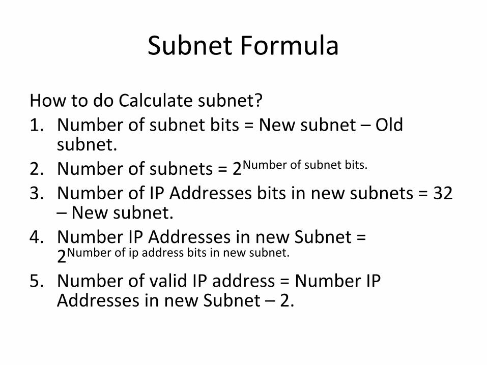
Subnet Formula
How to do Calculate subnet?1. Number of subnet bits = New subnet – Old
subnet.2. Number of subnets = 2Number of subnet bits.
3. Number of IP Addresses bits in new subnets = 32 – New subnet.
4. Number IP Addresses in new Subnet = 2Number of ip address bits in new subnet.
5. Number of valid IP address = Number IP Addresses in new Subnet – 2.

Chapter6Internal components of a Cisco router:• Bootstrap-Is used to bring the router up during initialization, it will boot the router
and then load the IOS.• Post (Power on self test)-it is used to check basic functionality of the router’s
hardware.• ROM Monitor-It is used to Manufacturing , testing and troubleshooting.• Mini IOS- called Boot loader , it is stored on ROM and can be used to bring the
interfaces and load cisco IOS into flash memory, many other functions.• RAM (Random access memory)- Used to hold packet buffers, routing table, Running
config is stored in RAM.• ROM (Read only memory)- Used to start and maintain the router• Flash Memory- Stores IOS image and other file can be taken as a backup.• NVRAM (Non volatile RAM)- Used to hold router’s and switch configuration
permanently.• Configuration Register-Used to control how router boots up, which tells router to
boot the IOS from flash as well as load the configuration from NVRAM.

Chapter7
For all configuration command please refer “Command reference”

Chapter 8 RoutingThere are two types of routing.1.IP Routing: Routing protocols like RIP, EIGRP, OSPF, BGP, learn the best path.2.IP Routed: Once best path is learned, actual data is transmitted using IPv4, IPv6IP Routing is further extended to other method of routing.1.Static routing2.Default routing3.Dynamic routing
Static routing:Static routing occurs when you manually add routes in each router’s routing table. Benefits:1.Less overhead on the router’s CPU2.Less bandwidth used between routers.3.It adds security. Disadvantages:1.The administrator must really understand the internetwork and how each router is connected in order to configure routes correctly.2. Administrative intervention is required at every point of change.3.It is not feasible in large network.
Default Routing
Default Routing: We use default routing when we have one exit interface to send all traffic to a remote destination network. You should only use default routing on stub networksDynamic Routing:• Dynamic routing is when protocols are used to find networks and update routing tables on
routers.• Administrative Distances:- is used to rate the trustworthiness of routing information received on
a router from a neighbor router. An administrative distance is an integer from 0 to 255, where 0 is the most trusted and 255 means no traffic will be passed via this route.
Routing Protocols:• Distance vector: The distance-vector protocols in use today fnd the best path to a remote
network by judging distance.• Link state: In link-state protocols, also called shortest-path-frst protocols, the routers each
create three separate tables. One of these tables keeps track of directly attached neighbors, one determines the topology of the entire internetwork, and one is used as the routing table. Link-state protocols send updates containing the state of their own links to all other directly connected routers on the network, which is then propagated to their neighbors.
• Hybrid: Hybrid protocols use aspects of both distance vector and link state for example, EIGRP.

Distance-Vector Routing Protocols RIP
• Routing Loops: Distance-vector routing protocols keep track of any changes to the internetwork by broadcasting periodic routing updates out all active interfaces.
• Maximum Hop Count: One way of solving this problem is to define a maximum hop count. RIP permits a hop count of up to 15, so anything that requires 16 hops is deemed unreachable.
• Split Horizon : Another solution to the routing loop problem is called split horizon. by enforcing the rule that routing information cannot be sent back in the direction from which it was received.
Route Poisoning: Another way to avoid problems caused by inconsistent updates and stop network loops is route poisoning. it sends an update, called a poison reverse, back to Router. This ensures that all routers on the segment have received the poisoned route information.Hold down: Hold downs prevent routes from changing too rapidly by allowing time for either the downed route to come back up or the network to stabilize somewhat before changing to the next best route.

Routing Information Protocol (RIP)
1.It is a one of IGP protocol and known as a distance vector protocol.2.It uses metric Hop count and selects best past based on hop count.3.It supports up to 15 hop counts.4.It uses Administrative distance of 120.5.It does load balancing up to four equal path.6.It supports class full routing.7.It sends out update using broadcast 255.255.255.255 8.It does not support authentication.9.It sends out periodic update in every 30 seconds.10. support for discontiguous networksWhat’s a discontiguous network? It’s one internetwork that has two or more subnetworks of a classfull network connected together by different classfull networks.

Timers
1.Update : 30 seconds2.Hold down : 180 seconds3.Invalid : 180 seconds4.Expire : 240 secondsRIP Version 2.1. It supports class less and support for discontiguous networks.2. It sends multicast at 224.0.0.9 instead broadcast at
255.255.255.2553. It uses manual summarization to save the bandwidth and cpu
load.4. It supports two types of authentication, Plain text and MD5.5. It sends triggered update.

Chapter 9:EIGRP1.It is an IGP protocol and known as a Hybrid protocol.2.It is a Cisco proprietary protocol.3.It uses Metric Bandwidth, delay, Reliability, load and MTU to select best path.4.DUAL (Defusing Update algorithm) is used to calculate the metric. 5.It supports up to 100 hop count and can be extended up to 255.6.It does load balancing up to four equal path and can do up to 16 unequal path by changing the variance command.7.It supports class less routing.8.It does auto summarization and also can do manual summarization.9.It is a Protocol dependent module (Supports multiple protocols including IPv4, IPv6, Apple talk etc)10.It supports MD5 authentication.11.It supports communication via Reliable Transport Protocol (RTP)12.It discovers neighbor automatically by sending hello in every 5 seconds, hold 15 seconds.13.It uses Autonomus system (AS) to separate its routing table.
EIGRP Protocol continuedLet’s define some terms before we move on:14.Feasiable Distance: The best metric among all paths to a remote network. The route with the lowest FD is the route that you will find in the routing table because it is considered the best path.The metric of FD is reported by Reported or Advertise Distance(AD).15.Reported/advertised distance (AD): This is the metric of a remote network, as reported by a neighbor16.Three tables used with EIGRP. 1.Routing Table 2.Neighbor Table 3.Topology Table17. Feasible successor: A feasible successor is a path whose advertised distance is less than the feasible distance of the current successor.EIGRP will keep up to 16 feasible successors in the topology table and one with the best metric will be copied to routing table.18. Successor: A successor route is the best route to a remote network.
Diffusing Update Algorithm (DUAL)-EIGRP uses Diffusing Update Algorithm (DUAL) for selecting and maintaining the best path to each remote network.
EIGRP Protocol continuedThis algorithm allows for the following:1.Backup route determination if one is available2.Support of VLSMs3.Dynamic route recoveries4.Queries for an alternate route if no feasible successor route can be foundUsing EIGRP to Support Large Networks:1. Support for multiple ASs on a single router2. Support for VLSM and summarization3. Route discovery and maintenanceThe formulae for calculating EIGRP metric is: Metric = 256*((K1*Bw) + (K2*Bw)/(256-Load) + (K3*Delay)*(K5/(Reliability + K4)))• k1=bandwidth• k2=load• k3=delay• k4=reliability• k5=MTUthe Metric would be 256 *( (k1 * BW) + (K3 * Delay))Metric = 256 * ((10000000 / slowest bandwidth) + cumulative delay)/

OSPF1.It is an IGP protocol and known as a Link state protocol.2.It is a open standard protocol.3.It uses Metric as a cost to select best path.4. It uses SPF algorithm and Dijkstra algorithm to calculate the metric. 5.It supports up to 255 hop count.6.It does load balancing up to four equal path.7.It supports class less routing, VLSM.8.It does not auto summarization and supports manual summarization.10.It supports Null0 , Type 1 clear text and Type 2 MD5 authentication .11.It supports communication via Reliable Transport Protocol (RTP)12.It discovers neighbor automatically by sending hello in every 10 seconds at multicast address 224.0.0.5, hold 40 seconds.13.It uses process id to separate its routing table.
OSPF Continued14.It breaks its big network into area.15. It uses LSA Link State Advertisement it is an OSPF data packet containing link-state and routing information that’s shared among OSPF routers. to advertise the routing update to neighbor routers16. Router ID- The Router ID (RID) is an IP address used to identify the router.OSPF Terminology:17. Three tables.Routing table-Neighbor table-Adjacency tableTopology table-Database table18-Designated router A DR is elected whenever OSPF routers are connected to the same multi-access network. Cisco likes to call these “broadcast” networks like Ethernet LAN.19-Backup designated router- A BDR is a hot standby for the DR on multi-access links.20-OSPF areas- An OSPF area is a grouping of contiguous networks and routers. All routers in the same area share a common Area ID.

OSPF Terminology
21-Broadcast- (multi-access)- Broadcast networks such as Ethernet allow multiple devices to connect to the same network.22.Non-broadcast multi-access- networks are types such as Frame Relay, X.25, and Asynchronous Transfer Mode (ATM). These networks allow for multi-access but have no broadcast ability like Ethernet.23.Point-to-point - consisting of a direct connection between two routers that provides a single communication path.
24.Point-to-multipoint – it refers to a type of network topology consisting of a series of connections between a single interface on one router and multiple destination routers.25.Cisco uses formula 10*8/Bandwidth, thus 100Mbps will have a cost 1 and 10Mbps cost 10, with bandwidth 64000 cost 1563

Chapter11:STP(Spanning tree protocol)
STP is used to prevent loop in L2 network by putting some ports in forwarding mode and some ports in blocking mode.Spanning-Tree Communication: Bridge Protocol Data Units- STP uses BPDU to communicate with connected switches using source as a unique mac address of port and destination multicast address 01-80-c2-00-00-00.BPDU’s are sent in every two secondsTwo types of BPDU exist: 1. Configuration BPDU, used for spanning-tree computation• 2. Topology Change Notification (TCN) BPDU, used to announce
changes in the network topology .Electing a Root Bridge Bridge Priority + MAC Address 2 bytes (32768) (lower) + 6 bytes (lower)
STP Continued
Spanning Tree term-Root Bridge-The RB is the bridge with the best bridge ID, and becomes central point of the network, Once RB is elected all other switch have to make single path to RB.Root Port-RP is always the link directly connected to the RB or the lowest path cost to RB.Designated Port-A DP is one which has been determined as having the best cost to the RB via its RP, and it is marked as a forwarding port.
Sequence of four conditions: 1.Lowest Root Bridge ID2. Lowest Root Path Cost to Root Bridge3. Lowest Sender Bridge ID4. Lowest Sender Port ID
STP Timers
STP States :
Disabled— when the port is shut down Blocking— a port cannot receive or transmit data and cannot add MAC addresses to its address table. Instead, a port is allowed to receive only BPDUs Listening— the port cannot send or receive data frames. However, the port is allowed to receive and send BPDUs Learning— The port cannot yet send any data frames , only can receive and send bpduForwarding— The port can send and receive data frames and send and receive BPDUs. STP Timers
Hello Time— 2 secondsForward Delay— The time interval that a switch port spends in both the Listening and Learning states. The default value is 15 seconds. Max (maximum) Age— The time interval that a switch stores a BPDU before discarding it. The default Max Age value is 20 seconds.
STP ContinueSpanning Tree PortFast-This is a feature where port does not have to wait 50 seconds to come up , it is implemented on access layers ports only.Spanning Tree UplinkFast- This is a Cisco feature where port does not have to wait 50 seconds to come up , it is implemented on trunk ports and on blocked ports only.Spanning Tree BackboneFast-This is also a Cisco feature which is used to determine and quickly fx link failures on the local switch, it should be implemented to all switches to allow for detection of indirect link failure.Rapid Spanning Tree Protocol (RSTP) 802.1w-It is the protocol with all features like portfast, uplinkfast, backbone fast, which are Cisco proprietary. Disabled = DiscardingBlocking = DiscardingListening = DiscardingLearning = LearningForwarding = Forwarding
EtherChannel
EtherChannel- it is a mechanism which allows us to use all the links as one bundle connected to another switch instead of using one link which is in forwarding state.There are two Etherchannel protocol. 1.Port Aggregation Protocol (PAgP)- Cisco proprietary. Modes -Desirable, auto , on2. Link Aggregation Control Protocol (LACP). Open standard Modes- active, passive, On.Port Security- We can also implement l2 security by using security command and can secure port by port.BPDUGuard- If a switch port that has BPDUGuard enabled receives a BPDU on that port, it will place the port into error disabled state.BPDUFilter- a switch port that has BPDUFilter enabled will not send and receive any BPDU.

Chapter 12:VLANs and Trunks
• VLAN Membership • Static VLAN configuration –vlan configuration is done
manually by network engineer based on port id.• Dynamic VLAN assignment – vlan configuration is
done automatically based on mac address of end users with the help of vlan membership policy server (VMPS)
• VLANs can be scaled in the switch block by using two basic methods:
• End-to-end VLANs- the vlan is available throughout the network.
• Local VLANs –vlans are located locally.

Vlan trunking
• There are two trunking protocols.• ISL protocol-1.It is a Cisco-proprietary method to encapsulate the vlan information.2. It adds 26 bytes of header and 4 bytes of trailer where The trailer contains a cyclic redundancy check (CRC) value to ensure the data integrity • 802.1Q protocol-1.It is open standard.2.It adds 4 bytes just after source address to encapsulate the vlan ID.
DTP: Dynamic trunking protocolDTP is a negotiation protocol that negotiates a common trunking mode between two switches. DTP frames sent out in every 30 second.switchport trunk encapsulation- it encapsulates the vlan info using ISL or dot1q or negotiate when vlan info is passed on trunk link.ISL- vlan’s are tagged using isl protocol . It does not support untagged vlanDot1q-Vlan’s are tagged using 802.1q protocol.Negotiate (default)- encapsulation is negotiated to select either ISL or 802.1q, and it depends which encapsulation protocol is supported in other end , if both ISL is preferred. C2950 does not support ISL encapsulation.
Imp==In the case of an IEEE 802.1Q trunk, you should configure the native VLAN with the switchport trunk native vlan command InterVLAN communication- It is possible to communicate between two L2 broadcast domain using either Router in a stuck or L3 switches.
VTP• VTP is used to relay all vlan information from one switch to another using
few parameters.VTP Modes Server mode— VTP has full control in this mode and it can add, delete and modify the vlan. All VTP information is advertised to other switches in the domain.Client mode— VTP clients do not allow to create, change, or delete any VLANs. It only sync with all vlans and forward it to another switches.Transparent mode— VTP transparent does not participate in VTP. a switch does not advertise its own VLAN configuration, and a switch does not synchronize its VLAN database with received advertisements. it can add, delete and modify the vlan, but any change in transparent mode will not be forwarded to connected switches.

Chapter 13:Layer 3 High Availability
Approaches to providing router redundancy: • Hot Standby Router Protocol (HSRP)• Virtual Router Redundancy Protocol (VRRP)• Gateway Load Balancing Protocol (GLBP)HSRP Overview: Basically, each of the routers that provides redundancy for a given gateway address is assigned to a common HSRP group. One router is elected as the primary, or active, HSRP router; another is elected as the stand by HSRP router; and all the others remain in the listen HSRP state. The routers exchange HSRP hello messages at regular intervals so that they can remain aware of each other’s existence and that of the active router.1. HSRP is a Cisco-proprietary protocol 2. HSRP sends its hello messages to the multicast destination 224.0.0.2 (“all
routers”) using UDP port 1985.3. Group number can be assigned from 0 to 2554. Hellos are sent every 3 seconds, hold time timer 10 sec, three times of
hello
HSRP Continued Switch(config-if)# standby grouptimers[msec] hello[msec] holdtime5. Preemption is disabled by default.6. HSRP supports two types of authentication , Plain text and MD5.Switch(config-if)# standby group authentication stringSwitch(config-if)# standby groupauthentication md5 key-string[0 |7] string7. HSRP supports tracking where it can track the interfaces and if any tracking interface is going down it will reduce the priority.HSRP Router Election: HSRP election is based on a priority value (0 to 255) By default, the priority is 100. The router with the highest priority value (255 is highest) becomes the active router for the group. If all router priorities are equal or set to the default value, the router with the highest IP address on the HSRP interface becomes the active router. Switch(config-if)# standby grouppriority prioritySwitch(config-if)# standby 1 priority 20
Switch(config-if)# standby groupip ip address[secondary]State sequence:1.Disabled, init, Listen, speak, standby, activeHSRP defines a special MAC address of the form 0000.0c07.acxx, where xx represents the HSRP group number as a two-digit hex value.Configuring an HSRP Group on a Switch: CatalystA(config)# interface vlan 50CatalystA(config-if)# ip address 192.168.1.10 255.255.255.0CatalystA(config-if)# standby 1 priority 200CatalystA(config-if)# standby 1 preemptCatalystA(config-if)# standby 1 ip 192.168.1.1Load Balancing with HSRP:• Two group can be sued to load balance the traffic One group assigns an active
router to one switch, The other group assigns another active router to the other switch.
Router# show standby[brief] [vlan vlan-id | type mod/num]

VRRP1.It is a open standard protocol.VRRP provides one redundant gateway address from a group of routers. The active router is called the master router, whereas all others are in the backup state. The master router is the one with the highest router priority in the VRRP group.VRRP group numbers range from 0 to 255; router priorities range from 1 to 254. (254 is the highest, 100 is the default.)2.The virtual router MAC address is of the form 0000.5e00.01xx, where xxis a two-digit hex VRRP group number.3.VRRP advertisements are sent at 1-second intervals. 4.Preemtion is enabled by default5. VRRP sends its advertisements to the multicast destination address 224.0.0.18 using IP protocol 1126. It supports tracking.7.It supports authentication , Plain text and MD5
Gateway Load Balancing Protocol1. GLBP is a Cisco-proprietary protocol 2. GLBP is available only for the Catalyst 6500 Supervisor 23. GLBP sends its hello messages to the multicast destination 224.0.0.2 (“all
routers”) using UDP port 1985.4. GLBP group numbers range from 0 to 1023.5. The router priority can be 1 to 255 (255 is the highest priority),
defaulting to 1006. Preemption is enabled.7. Hellos 3 seconds, hold time timer 10 sec, three times of hello8. Track can be configured using GLBPTo provide a virtual router, multiple switches (routers) are assigned to a common GLBP group. Instead of having just one active router performing forwarding for the virtual router address, allrouters in the group can participate and offer load balancing by forwarding a portion of the overall traffic.

Active Virtual Gateway: The trick behind this load balancing lies in the GLBP group. One router is elected the active virtual gateway(AVG). This router has the highest priority value, or the highest IP address in the groupActive Virtual Gateway:Each router participating in the GLBP group can become an AVFThe virtual MAC addresses always have the form 0007.b4xx.xxyy. The 16-bit value denoted by xx.xx represents six zero bits followed by a 10-bit GLBP group number. The 8-bit yy value is the virtual forwarder number.Switch(config-if)# glbp grouppriority levelSwitch(config-if)# glbp grouppreempt[delay minimum seconds]Switch(config-if)# glbp grouptimers[msec] hellotime[msec] holdtime
GLBP Load Balancing: GLBP Load Balancing: load-balancing methods.Round robin—Each new ARP request for the virtual router address receives the nextavailable virtual MAC address in reply.Weighted—The GLBP group interface’s weighting value determines the proportionof traffic that should be sent to that AVF. A higher weighting results in more frequent ARP replies Host dependent—Each client that generates an ARP request for the virtual router address always receives the same virtual MAC address in reply. This method is used if the clients have a need for a consistent gateway MAC address. Switch(config-if)# glbp groupload-balancing[round-robin |weighted |host-dependent]Switch(config-if)# glbp groupip[ip-address[secondary]]
Chapter14:Security
• An access list is essentially list of conditions that categorize packets, and we can filter out unwanted packets entering to the network.
There are few rules for ACL.• It’s always compared with each line of the access list in sequential
order—that is, it’ll always start with the first line of the access list, then go to line 2, then line 3, and so on.
• It’s compared with lines of the access list only until a match is made. Once the packet matches the condition on a line of the access list, the packet is acted upon and no further comparisons take place.
• There is an implicit “deny” at the end of each access list—this means that if a packet doesn’t match the condition on any of the lines in the access list, the packet will be discarded.

ACL Continued
• There are two main types of access list.1.Standard access list-All decision made based on source IP address. you can create acl using number 1-99 or 1300-19992.Exteneded access list-All decisions are made based on L3 and L4 information and checks source and destination both to match the condition.you can create acl using number 100-199 or 2000-2699Named access list- It can be either standard or Extended access list instead of number we have to use the name.Controlling VTY (Telnet/SSH) access-Remarks- Using remark you can make an entry along with ACL, it is just like description.

Turning Off and Configuring Network services
Blocking SNMP port- to block the SNMP port you can implement access list.(config)#access-list 110 deny udp any any eq snmp(config)#interface s0/0(config-if)#access-group 110 inDisabling Echo-(config)#no service tcp-small-servers(config)#no service udp-small-serversTurning off BootP and Auto-Config-(config)#no ip boot server(config)#no service configDisabling the HTTP Interface-(config)#no ip http serverDisabling IP source Routing- Disabling packets with source routing header.(config)#no ip source-route

Continued• Disabling Proxy arp- It is the technique in which one host usually a router
answers ARP requests intended for another machine by faking it’s identity and router accepts the responsibility to getting real destination.
(config-if)#no ip proxy-arp• Disabling redirect message-icmp is used to generate logs to host and tells
the status of packets, by disabling this we can prevent the complete path information to be known.
(config-if )#no ip redirectsDisabling the generation of icmp unreachable message-It will no tell the subnet information to connected device after disabling this.(config-if )#no ip unreachablesDisabling Multicast route caching- it will prevent multicast route information.(config-if )#no ip mroute-cacheDisabling Maintenance operation protocol (MOP)- It works in L2 and L3 in DECnet protocol, and used to upload , download system software.

Chapter 15:NAT
• When Do We Use NAT?• You need to connect to the Internet and your hosts don’t
have globally unique IP addresses.• You change to a new ISP that requires you to renumber
your network.• You need to merge two intranets with duplicate addresses. Advantages-• Legally registered addresses.• Remedies address overlap occurrence.• Increases flexibility and security when connecting to
Internet.• Eliminates address renumbering as network changes.
Types of Network Address Translation
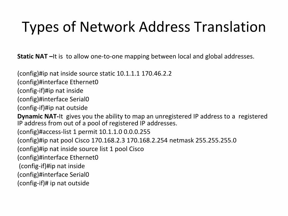
Static NAT –It is to allow one-to-one mapping between local and global addresses.
(config)#ip nat inside source static 10.1.1.1 170.46.2.2(config)#interface Ethernet0(config-if)#ip nat inside(config)#interface Serial0(config-if)#ip nat outsideDynamic NAT-It gives you the ability to map an unregistered IP address to a registered IP address from out of a pool of registered IP addresses.(config)#access-list 1 permit 10.1.1.0 0.0.0.255(config)#ip nat pool Cisco 170.168.2.3 170.168.2.254 netmask 255.255.255.0(config)#ip nat inside source list 1 pool Cisco(config)#interface Ethernet0 (config-if)#ip nat inside(config)#interface Serial0(config-if)# ip nat outside

ContinuedOverloading or PAT- It maps multiple unregistered IP addresses to a single registered IP address (many-to-one) by using different source ports. (Config)#access-list 1 permit 10.1.1.0 0.0.0.255(Config)#ip nat pool globalnet 170.168.2.1 170.168.2.1 netmask 255.255.255.0(Config)#ip nat inside source list 1 pool globalnet overload(config)#interface Ethernet0(config-if)#ip nat inside(config)#interface Serial0(config-if)#ip nat outsideNAT Names-Inside local-Name of inside source address before translationOutside local-Name of destination host after translationInside global-Name of inside host after translationOutside global-Name of outside destination host before translation
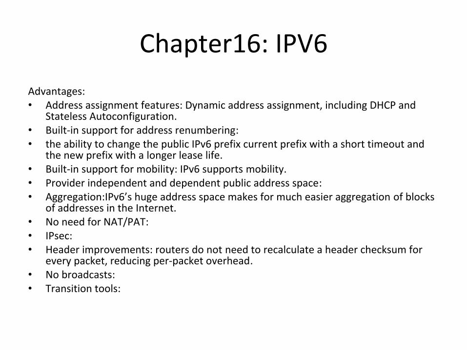
Chapter16: IPV6Advantages:• Address assignment features: Dynamic address assignment, including DHCP and
Stateless Autoconfiguration.• Built-in support for address renumbering:• the ability to change the public IPv6 prefix current prefix with a short timeout and
the new prefix with a longer lease life.• Built-in support for mobility: IPv6 supports mobility.• Provider independent and dependent public address space:• Aggregation:IPv6’s huge address space makes for much easier aggregation of blocks
of addresses in the Internet.• No need for NAT/PAT:• IPsec:• Header improvements: routers do not need to recalculate a header checksum for
every packet, reducing per-packet overhead.• No broadcasts:• Transition tools:

Conventions
• IPv6 conventions use 32 hexadecimal numbers, organized into 8 quartets of 4 hex digits separated by a colon, to represent a 128-bit IPv6 address, for example:
2340:1111:AAAA:0001:1234:5678:9ABC:1111• two conventions allow you to shorten an IPv6 address:1. Omit the leading 0s in any given quartet.2. Represent one or more consecutive quartets of all hex 0s withclassful and classless view of IPv4 addresses:Network + Subnet + Host Classful ipv4 addressingPrefix + Host Classless ipv4 addressing
IPv6 view of addressing and prefixes: Prefix + Host IPv6 addressing
IPv6 Continued
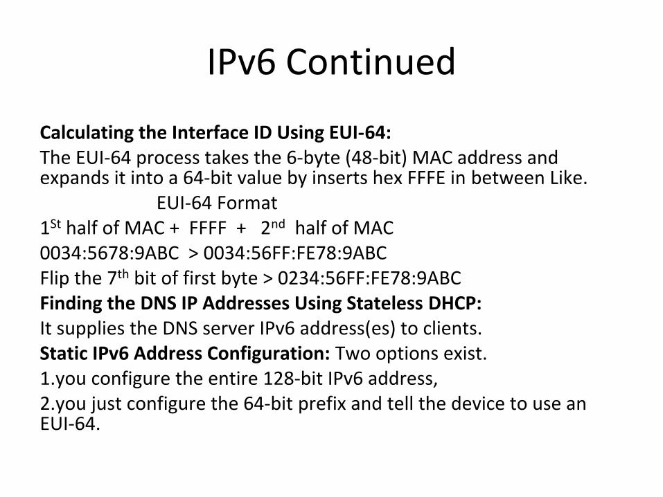
Calculating the Interface ID Using EUI-64:The EUI-64 process takes the 6-byte (48-bit) MAC address and expands it into a 64-bit value by inserts hex FFFE in between Like. EUI-64 Format1St half of MAC + FFFF + 2nd half of MAC 0034:5678:9ABC > 0034:56FF:FE78:9ABCFlip the 7th bit of first byte > 0234:56FF:FE78:9ABCFinding the DNS IP Addresses Using Stateless DHCP: It supplies the DNS server IPv6 address(es) to clients. Static IPv6 Address Configuration: Two options exist.1.you configure the entire 128-bit IPv6 address, 2.you just configure the 64-bit prefix and tell the device to use an EUI-64.
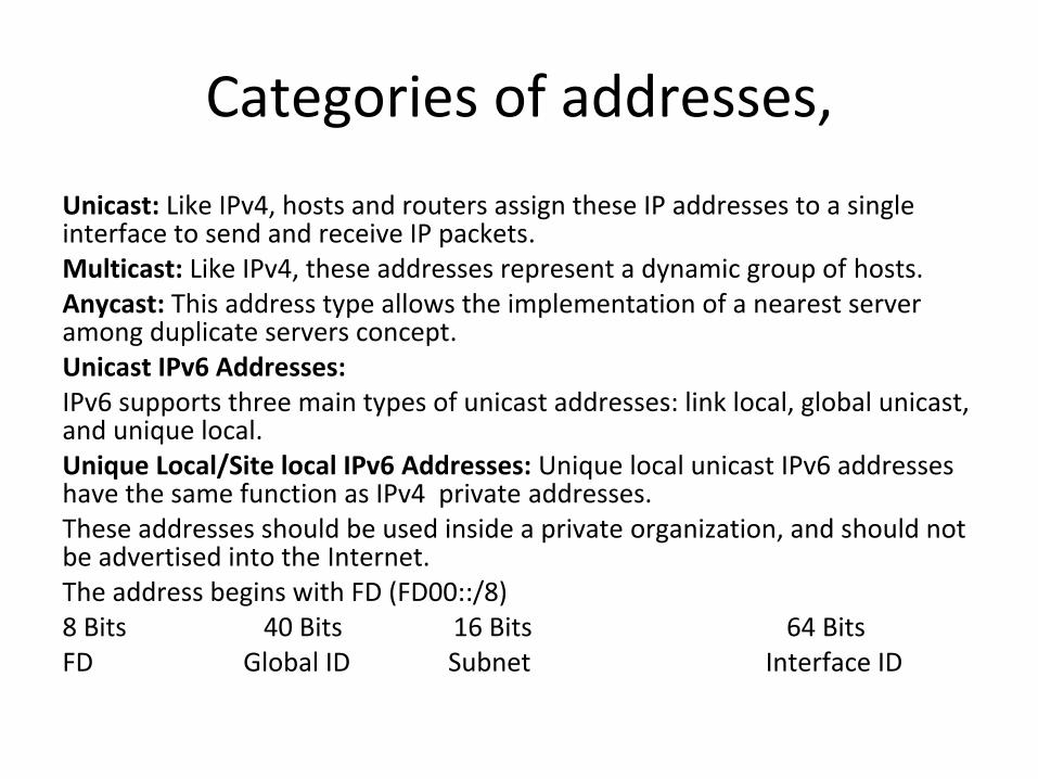
Categories of addresses,Unicast: Like IPv4, hosts and routers assign these IP addresses to a single interface to send and receive IP packets.Multicast: Like IPv4, these addresses represent a dynamic group of hosts.Anycast: This address type allows the implementation of a nearest server among duplicate servers concept.Unicast IPv6 Addresses:IPv6 supports three main types of unicast addresses: link local, global unicast, and unique local. Unique Local/Site local IPv6 Addresses: Unique local unicast IPv6 addresses have the same function as IPv4 private addresses.These addresses should be used inside a private organization, and should not be advertised into the Internet.The address begins with FD (FD00::/8) 8 Bits 40 Bits 16 Bits 64 BitsFD Global ID Subnet Interface ID

IPv6 ContinuedLink Local Unicast Addresses: IPv6 uses link local addresses for sending and receiving IPv6 packets on a single subnet, It starts with FE80::/10 range the first 10 bits must be 1111 1110 10. the address always starts FE80, because the automatic process sets bits 11-64 to binary 0s.10 Bits 54 Bits 64 BitsFE80/10 All 0s Interface ID• Used as the source address for RS and RA messages for router discovery.• Used by Neighbor Discovery.• As the next-hop IPv6 address for IP routes.Global Unicast IPv6 Addresses: All addresses whose first 3 bits are equal to the first 3 bits of hex number 2000 (bits are 001). Which is considered as a public ipv6 address.

IPv6 Continued• Term Assignment ExampleRegistry prefix By IANA to an RIR 2340::/12ISP prefix By an RIR to an ISP1 2340:1111/32Site prefix By an ISP 2340:1111:AAAA/48Subnet prefix For each individual 2340:1111:AAAA:0001/64• Method to assign the ipv6 address.Stateful DHCP, Stateless autoconfig, Static configuration, Static config with EUI-64Stateful DHCP for IPv6: IPv6 hosts can use stateful DHCP to learn and lease an IP address and corresponding prefix length (mask), and the DNS IP address(es), it is just like ipv4 DHCP, One difference between DHCPv4 and stateful DHCPv6 is that IPv4 hosts send IP broadcasts to find DHCP servers, whereas IPv6 hosts send IPv6 multicasts at FF02::1:2, other difference, IPv6 does not give any default router.
Stateless AutoconfigurationStateless autoconfiguration allows a host to automatically learn the key pieces of addressing information–prefix, host, and prefix length–plus the default router IP address and DNS IP addresses. Step1:IPv6 Neighbor Discovery Protocol (NDP), particularly the router solicitation and router advertisement messages, to learn the prefix, prefix length, and default router.Step2:Some math to derive the interface ID (host ID) portion of the IPv6 address, using a format called EUI-64Step3:Stateless DHCP to learn the DNS IPv6 addressesLearning the Prefix/Length and Default Router with NDP Router Advertisements: ICMPv6 messages called , Router solicitation (RS) is sent by computer at FE02::2 to find out all connected routers for default gateway IP and all known IPv6 prefix on link . Router will use Router Advertisement (RA) at FE02::1 to reply to all nodes.
Multicast IPv6 addressAll IPv6 multicast addresses begin with FF::/8 in other words, with FF as the first two digits, But most of the multicast addresses referenced in this chapter, begin with FF02::/16.All IPv6 nodes on the linkFF02::1All IPv6 routers on the link FF02::2OSPF messages FF02::5, FF02::6RIP-2 messages FF02::9EIGRP messages FF02::ADHCP relay agents FF02::1:2DHCP servers (site scope) FF05::1:3All NTP servers (site scope) FF05::101Layer 2 Addressing Mapping and Duplicate Address Detection:Neighbor Discovery Protocol for Layer 2 Mapping works just like IPv4 ARP, which is used to map mac from IP address.Host send Neighbor solicitation (NS) to at FE02::2 asking MAC address of data link.Router replies using Neighbor Advertisement (NA) and listing its MAC of data link.
Duplicate Address Detection (DAD)
The purpose of this check is to prevent hosts from creating problems by trying to use the same IPv6 address already used by some other host on the link.Process: A host sends the NS message to the solicited node on its own IPv6 address. If some host sends a reply, listing the same IPv6 address as the source address, the original host has found that a duplicate address exists.Inverse Neighbor Discovery:On Frame Relay networks, and with some other WAN data link protocols, the order of discovery is reversed.Router IOS IPv6 Configuration Command Reference:1.ipv6 address address/length > Static configuration of the entire IPv6 unicast address.2.ipv6 address prefix/lengtheui-64> Static configuration of the first 64 address bits; the router derives the last 64 bits with EUI-64.

Commands
3.ipv6 address autoconfig > Router uses stateless autoconfig to find address.4. ipv6 address dhcp > Router uses stateful DHCP to find address.5. ipv6 unnumbered interface-type number > Uses the same IPv6 unicast address as the referenced interface.6. ipv6 enable > Enables IPv6 on the interface, but results in only a link local address.7. ipv6 addressaddresslink-local > Overrides the automatically created link local address. The configured value must conform to the FE80::/10 prefix.8. ipv6 addressaddress/lengthanycast > Designates that the unicast address is an anycast.
Chapter17:Wireless
Differences Between WLAN and LAN:– WLANs use radio waves as the physical layer.
• WLANs use CSMA/CA instead of CSMA/CD for media access.• Two-way radio (half-duplex) communication.
– Radio waves have problems that are not found on wires.• Connectivity issues:
– Coverage problems – Interference, noise
• Privacy issues – Access points are shared devices similar to an Ethernet
hub for shared bandwidth.– WLANs must meet country-specific RF regulations.
Wireless
• WPAN,WLAN,WMAN,WWAN• Devices: Access point, WNIC, Antenna• 802.11 {IEEE, FCC, ETS, Wi-Fi Alliance}• Unlicensed Bands 900MHz, 2.4GHz, 5 GHz• CSMA-CA,802.11b, 802.11g, 802.11a, 802.11n• Topologies: IBSS, BSS, ESS• SSID, WEP, TKIP, AES,