Embed Size (px)
Citation preview

NAT'L INST OF STAND & TECH
A111D7 ElDfiSD


National Bureau of Standards
JUL 2 8 1953
8IG5I
TA4I0
.U48

National Bureau of Standards
Library, N. W. Bldg.
AUG 1 9 1952
Wet Venting of Plumbing Fixtures
United States Department of Commerce
National Bureau of Standards
Building Materials and Structures Report BMS119
BUILDING MATERIALS AND STRUCTURES REPORTS
On request, the Superintendent of Documents, U. S. Government Printing Office, Wash-ington 25, D. C, will place your name on a special mailing list to receive notices of new reportsin this series as soon as they are issued. There will be no charge for receiving such notices.
An alternative method is to deposit with the Superintendent of Documents the sum of $5,
with the request that the reports be sent to you as soon as issued, and that the cost thereofbe charged against your deposit. This will provide for the mailing of the publications withoutdelay. You will be notified when the amount of your deposit has become exhausted.
If 100 copies or more of any report are ordered at one time, a discount of 25 percent is allowed.Send all orders and remittances to the Superintendent of Documents, U. S. Government Printing
Office, Washington 25, D. C.
The following publications in this series are available by purchase from the
Superintendent of Documents at the prices indicated:
BMSl Research on Building Materials and Structures for Use in Low-Cost Housing *
BMS2 Methods of Determining the Structural Properties of Low-Cost House Constructions.- 10^BMS3 Suitability of Fiber Insulating Lath as a Plaster Base 15^BMS4 Accelerated Aging of Fiber Building Boards 10^BMS5 Structural Properties of Six Masonry Wall Constructions. 15^BMS6 Survey of Roofing Materials in the Southeastern States 15fi
BMS7 Water Permeability of Masonry Walls *
BMS8 Methods of Investigation of Surface Treatment for Corrosion Protection of Steel 15^BMS9 Structural Properties of the Insulated Steel Construction Co.'s "Frameless-Steel" Con-
structions for Walls, Partitions, Floors, and Roofs 10^BMSIO Structural Properties of One of the "Keystone Beam Steel Floor" Constructions
Sponsored by the H. H. Robertson Co lOfi
BMSll Structural Properties of the Curren Fabrihome Corporation's "Fabrihome" Construc-tions for Walls and Partitions 10^
BMS12 Structural Properties of "Steelox" Constructions for Walls, Partitions, Floors, andRoofs Sponsored by Steel Buildings, Inc 15^
BMS13 Properties of Some Fiber Building Boards of Current Manufacture 10^BMS14 Indentation and Recovery of Low-Cost Floor Coverings 10^BMS15 Structural Properties of "Wheeling Long-Span Steel Floor" Construction Sponsored
by the Wheeling Corrugating Co 10^BMS16 Structural Properties of a "Tilecrete" Floor Construction Sponsored by Tilecrete
Floors, Inc lOfi
BMS17 Sound Insulation of Wall and Floor Constructions 20^Supplement to BMS17, Sound Insulation of Wall and Floor Constructions 5^Supplement No. 2 to BMS17, Sound Insulation of Wall and Floor Constructions 10^BMS18 Structural Properties of "Pre-fab" Constructions for Walls, Partitions, and Floors
Sponsored by the Harnischfeger Corporation 10^BMS19 Preparation and Revision of Building Codes tBMS20 Structural Properties of "Twachtman" Constructions for Walls and Floors Sponsored
by Connecticut Pre-Cast Buildings Corporation lOfi
BMS21 Structural Properties of a Concrete-Block Cavity-Wall Construction Sponsored by theNational Concrete Masonry Association 1 10^
BMS22 Structural Properties of "Dun-Ti-Stone" Wall Construction Sponsored by the W. E.Dunn Manufacturing Co 10^
BMS23 Structural Properties of a Brick Cavity-Wall Construction Sponsored by the BrickManufacturers Association of New York, Inc 10^
BMS24 Structural Properties of a Reinforced-Brick Wall Construction and a Brick-Tile Cavity-Wall Construction Sponsored by the Structural Clay Products Institute 15fS
BMS25 Structural Properties of Conventional Wood-Frame Constructions for Walls, Parti-tions, Floors, and Roofs 20^
BMS26 Structural Properties of "Nelson Pre-Cast Concrete Foundation" Wall ConstructionSponsored by the Nelson Cement Stone Co., Inc 10^
BMS27 Structural Properties of "Bender Steel Home" Wall Construction Sponsored by theBender Body Co lO^i
BMS28 Backflow Prevention in Over-Rim Water Supplies 15^BMS29 Survey of Roofing Materials in the Northeastern States 20^BMS30 Structural Properties of a Wood-Frame Wall Construction Sponsored by the Douglas
Fir Plywood Association 15^BMS31 Structural Properties of "Insulite" Wall and "Insulite" Partition Constructions
Sponsored by The Insulite Co 25^•Out of print.tSuperseded by BMS116.
[List continued on cover page in]

UNITED STATES DEPARTiMENT OF COMMERCE • Cliaiics Sawyer, i^icrelary
NATIONAL BUREAU OF STANDARDS • F. U. Condon /Jimlor
Wet Venting of Plumbing Fixtures
by John L. French, Herbert N. Eaton, and Robert S. Wyly
Building Materials and Structures Report BMS119
Issued December 1, 1950
For sale by the Superintendent of Documents, U. S. Government Printing Office.Washington 25, D. C.
Price 20 cents

ForewordThis report on the wet venting of plumbing fixtures is the second of a
series of three National Bureau of Standards reports giving the results of an
investigation of the problems involved in the proper venting of single plumb-
ing fixtures or a relatively small group of such fixtures, the first report being
BMS118, Stack V'enting of Plumbing Fixtures, published in January 1950.
This investigation was sponsored by the Housing and Home Finance Agency
as a part of the continued efforts of that Agency to secure rational and econom-
ical design of housing.
A fixture is said to be wet vented when its vent serves also to carry the dis-
charge from fixtures connecting into the drainage system at a higher level.
The use of wet venting reduces the number of individual vent pipes required
hj a plumbing drainage system as contrasted with the number required by the
conventional back-vented system and hence reduces the cost of the venting
system. This fact has led to an increasing tendency among code-writing
authorities to permit the wet venting of plurhbing fixtures under certain cir-
cumstances. One of the objects of this investigation was to determine under
what circumstances it is legitimate to use this form of venting in order to
afford a sound basis for code provisions relating to this matter.
Drainage pipes of various materials are referred to in this report as form-
ing parts of one or more of the test systems constructed for use in the investi-
gation. These materials were used merely because of their availability at the
time when the systems were constructed, and the fact that they were so used
should not be construed as constituting an approval or recommendation of
those materials in preference to any other matei'ials that might have been used.
The research forming the basis for this report was first undertaken for the
National Housing Agency in connection with the Veterans Emergency Hous-
ing Program of that Agency and was continued and completed under the
Housing Research Program of the Office of the Administrator, Housing and
Home Finance Agency, as part of the research program of that Agency under
its statutor}^ authority.
E. U. Condon, Director.

Wet Venting of Plumbing Fixtures
This report gives the results of laboratory tests of various wet-vented single and two-
story plumbing drainage systems. A suggested test or design loading for such systems is
developed, and a permissible trap-seal loss for the fixtures of wet-vented systems is proposed.
Conclusions regarding the linfits under which wet-vented fixtures located on the upper floor
of a system will operate satisfactorily are given in a form sufficiently simple for inclu.sion in
John L. French, Herbert N. Eaton, and Robert S. Wyly
plumbing codes.
CONTENTSPage
Foreword II
I. Introduction 2
II. Scope of the investigation 2
III. Previous investigations of the performance of wet-vented fixtures 3
IV. Nature of the phenomena involved in wet venting 4
\. Tests on a single-story wet-vented system with lavatory and combination fixtures
connected to the wet vent 5
1. Description of the test system 5
2. Test procedure 7
3. Test results 8
a. Tub not discharged 8
b. Tub discharged 11
4. Interpretation of test results 12
a. Loads on the drainage system from a single group of bathroom fixtures
and a combination fixture 13
b. Permissible trap-seal losses 16
c. Permissibility of venting a bathtub trap with a wet vent to which a
lavatory and a combination fixture are connected 16
d. Summary 17
VI. Factors affecting the performance of wet-vented systems 17
1. Length of horizontal branch 17
2. Slope of horizontal branch 18
3. Diameter of horizontal branch . 18
4. Tub drain length and slope 19
5. Trap dimensions - 20
6. Effect on the trap-seal losses of a wet-vented bathtub of increasing the
diameters of the lavatory and combination fixture drains 21
7. Diameter of bathtub drain 23
VII. Tests on a single-story wet-vented system with only a lavatory connected to the
wet vent 24
VIII. Tests on two-story, duplex, wet-vented system 25
IX. Wet-vented fixtures on the lower floors of multi-story buildings 27
X. Conclusions 27
XI. References 27
1

I. Introduction
Plumbing fixtures ordinarily discharge into the
building drainage system through traps located
between the fixture and the fixture drain. Thefunction of a fixture trap (see fig. 3) is to provide
a water seal between the drainage system and the
interior of the building in order that sewer gas in
objectionable quantities will not flow from the
drainage s^ystem into the building. The discharge
of fixtures creates pressure fluctuations in the
drainage system, which, if excessive, wifl reduce
the water seals in the fixture traps and hence mayrender them unable to perform their function. In
order to control the pressures in the drauiage
system so that the water seals of fixture traps will
not be reduced excessively, vent pipes connecting
various points hi the drainage system with the
atmosphere are ordinarily installed. The termpressure as used in this report refers to pressures
either above or below atmospheric pressure.
The pressures in a draiaage system that mayafl'ect the water seals of fixture traps adversely
may be classified conveniently into two groups
—
pressures caused by the discharge of the fixtures
connected to the fixture trap in question andpressures caused by the discharge of other fixtures
in the system. The trap-seal losses caused bythe first group are said to be due to self-siphonage,
and, in order to control the trap-seal losses due to
this cause, it is necessary to have the vent located
relatively near the fixture trap. For this reasonit is customary to provide some type of vent ade-quate for the protection of each fixture trap of a
plumbing drainage system. However, in this
connection the argument has been advanced that
adequate protection of a fixture trap b}^ a ventdoes not necessarily imply that each fixture trap
requires a separate vent, and it has been suggestedthat various tA^es of group venting, in which a
single vent serves more than one fixture, provideadequate protection to fixture traps and providean acceptable method of decreasing the cost of the
plumbing system.The venting of groups of fixtures by a single
vent may take two basic forms. These are shownin figure 1. In the arrangement of figure 1, A,two fixtures connected at the same level to a verti-
cal drain use the same vent. The vent in this
case carries only air and is sometimes termed adual or common vent. In figure 1, B, the upperfixture is vented m the conventional manner. Its
vent carries only air and is the only type of ventpermitted by many plumbing codes. However,the lower fixture in figure 1, B, does not have anindividual vent that carries only air. Its vent is
frequently termed a wet vent because it carries thedischarge of the upper fixture, as well as whatever
- DU»L VENT
A B
FiGUEE 1. Basic group-venting arrangements.
air may travel along the pipe to relieve pressuresat the lower fixture drain.
The use of wet vents has the general effect of
reducing the number of individual vent pipesrequired by the plumbing drainage system as com-pared with the conventional back-vented system,
and for this reason results in a reduction in cost
of the venting system. Because of the possible
economies involved, there has been an increasing
tendency among code-wiiting authorities to permitthe wet venting of plumbing fixtures under certain
circumstances. However, there has been no una-nimity among these authorities as to the adequacyof wet venting, and many codes prohibit the use of
wet vents altogether. For this reason the Uni-form Plumbing Code Committee believed, in viewof the economic advantages involved, that anexperimental investigation of the merits of wetventing of plumbing fixtures was fully justified,
and the Housing and Home Finance Agency spon-sored such an investigation at the National Bureauof Standards. The purpose of this report is to
present the results of that investigation.
II. Scope of Investigation
A great many variations in the basic wet-ventedarrangement of figure 1, B, are possible. Somearrangements that are permitted by variousplumbing codes are shown in figure 2. In this
connection, it will be observed that the arrange-ment shown in figure 2, F, is of the type commonlyreferred to as a stack-vented installation. Currentterminology in the plumbing industry looselydescribes the group of fixtures in figure 2, F, as
stack-vented, while in reality onty the topmostfixture is stack-vented, and the thi-ee lower fixtures
are wet-vented in the sense that the vent to the
lower fixtures —in this case the stack —also carries
waste from the upper fixtures. A report on stackventing has already been published \ and henceit will not be considered further here.
' Figures in brackets refer to references at the end of this report.
2 Wet Venting of Plmnhing Fixtures

The rosults of laboratory tests on installations
containing the type of wet-venting shown in
figures 2, A, 2, B, and 2, E, will be presented in
this report.
COMBINATIONFIXTURE
D E F
Figure 2. Wet-venting arrangements.
Since the function of the venting system is to
prevent the occurrence of excessive seal losses
in the fixture traps of the system, the efficiency
of a venting system can be measured in terms of
the trap-seal losses caused by the discharge of a
particular group of fixtures. In this connection
a trap-seal loss of 1 inch is sometimes [1, 2] con-
sidered the dividing line between satisfactory andunsatisfactory performance. Although this cri-
terion of satisfactory trap performance, which has
been based solely on personal judgment, is arbi-
trary and is undoubtedly overly conservative in
all installations in which the stack, building drain,
and venting systems are not loaded to capacity, it
is nevertheless adequate for the purpose of this
investigation and has been used throughout this
report as tlic line of (Iciiiiii-ciU ion bclwccii satis-
factory and unsatisfactory trap pcrformarH-c.
The specific problem of this investigation tlius
becomes one of determining the limitations on the
lengths, slopes, and diameters of the drains in the
installations of figures 2, A, 2, B, and 2, E, re-
quired to prevent the o(;currenc(^ of ti'ajj-seal
losses in excess of 1 inch, when a reasonable test
loading consisting of the simultaneous discharge of
a particular group of fixtures is ap])lied lo I lie
system.Although wet-vented fixtures may be used satis-
factorily under certain conditions on all floors of aplumbing drainage system, the experimental in-
vestigation reported here was confined to wet-vented fixtures on the top floor of a building.
The terms trap weir, trap-seal loss, and depth
of trap seal will be used frequently in this report,
and their significance is shown in figure 3.
TRAP WEIR
Figure 3. Definition sketch of trap.
ft=trap-.seal loss.
i=trap seal.
III. Previous Investigations of the Performance of Wet-Vented Fixtures
In 1924 Roy B. Hunter [2] reported in detail theresults of tests with certain types of wet-ventedsystems. Tests with the fixture arrangementshown in figure 4, A, located on the first fioor of atwo-story system and with a 1 /4-inch-diameterwet vent led Hunter to draw the conclusions (1)
that each small waste connecting independentlyto the stack must be vented separately, (2) thatconsidering the slight probability of all the fixtures
of the group above discharging at the same time as
the basin or bathtub in the lower group, the watercloset may be left w^ithout a separate vent withcomparative safety, and (3) that with heavierdischarges from above than described the watercloset should be separately vented.
Hunter's tests of the same arrangement on thetop floor resulted in no seal losses in any of the
fixture traps, and he concluded that the wet vent-ing of a bathtub by the drain from a lavatory
such as shown in figiire 4, A, was also satisfactory
on the top floor of a building.
Hunter also investigated the problem of wetventing on the upper floor as applied to twobathrooms back-to-back, with the vertical dramof the two lavatories serving as a wet vent for the
two bathtubs. The test installation is illustrated
in figure 4, B. Hunter's conclusion was that,
for duplex installations of the type shown, the
wet vent was not sufficient to prevent a material
trap-seal reduction in one of the bath tub traps
when the other bathtub was discharged and that
a back vent to the two tubs as shown in figure
4, B, was required to prevent this from occurring.
In this connection, it may he pointed out that,
Building Materials and Structures Report BMS119 3

SINK
A B
TOP OR SECOND FLOOR TOP FLOOR
Figure 4. Hunter's test system.
since the observed trap-seal loss occurred whenneither of the lavatories was discharged, the
reduction in trap seal observed was not caused byany lack of efficiency of the wet vent from the
lavatories. The specific test merely indicated
that the discharge of one bathtub into an unvented
vertical drain resulted in a reduction in pressure
in the vertical drain sufficient to cause a sub-stantial seal loss in any trap connected to the
vertical section of the drain in question.
Hunter, in a later publication [3], although notreporting t*st data, indicates that the wet ventingof bathroom fixtures back-to-back is satisfactory,
provided the bathtub draiiis between the wet ventand the bathtub traps are laid on a uniform slope
and otherwise comply with the restrictions neces-
sary to prevent self-siphon age.
It will be observed that Hunter's test mstalla-
tion shown in figure 4, A, is for all practical
purposes identical with figure 2, A. Experimentaldata on the other two test mstallations of this
investigation, figures 2, B, and 2, E, have not beenpublished heretofore, but wet-venting arrange-ments identical with either one or both of these
installations have been described in at least twopublications [3, 4] as representing safe practice.
IV. Nature of the Phenomena Involved in Wet Venting
The physical phenomena occurring in wetventing are complicated, and the tests of this
project were not sufficiently extensive, andneither was it their primary purpose, to delmeateclearly in detail the processes involved. Never-theless, many of the tests were made withtransparent plastic tubing and fittings, and ageneral qualitative, although by no means com-plete, description of the functioning of a wet ventwas made possible thereby.
In the tests made with transparent tubing onthe test installation shown ui figure 2, B, it wasobserved that, if the flow through the wet ventwas started before or at the end of the period of
tub discharge, the tub drain remained substantiallyfilled with water, and small quantities of air
bubbled from the wet vent through the tub wasteand formed a pocket in the drain at the trap, withthe air-water interface forming, of course, ahorizontal plane.
As discharge continued through the wet vent andair bubbles continued to move up the tub drainfrom the air pocket over the trap, a gradual lower-ing of the water surface occurred. At the end of
the period of flow from the wet vent, a group of
large air bubbles moved rapidly upstream towardthe trap, immediately relieving the vacuum overthe ti-ap weii' and allowing the water seal in thetrap to return to equilibrium.
If, prior to the end of flow through the wet vent,sufficient air had been admitted to the tub drainto I'educe the depth of water over the trap weirto a small value or to zero, a larger trap-seal loss
was obtained than if only a small pocket of air
formed and the depth of water over the trap weij-
was relatively large. This was due to the factthat, if the depth of water over the trap weir wasrelatively large at the time when flow through the
wet vent ceased, the trap was refilled, at least in
part, by flow from the tub drain into the tub trap,
and only a small, if any, trap-seal reductionresulted. On the other hand, if the pocket of air
was large enough so that the water level in the tubdrain was at or below the tub-trap weir, there wasnot in general any flow of water from the draininto the trap, and large trap-seal losses wouldresult under certain conditions.
In these tests, in which the tub was dischargedwhile flow from the wet vent was occurring, the
amount of the tub trap-seal loss thus dependedupon the size of the aii- pocket m the tub drain andmore speciflcally upon the height of the watersurface in the tub drain with respect to the trap
weir. The depth of water over the trap weir wasobserved to depend on a number of factors, someof them being relatively indefinite.
First, and as would be expected, the watersurface in the tub drain could be made to remainabove the trap weir with small or no resulting trap-
seal losses by making the tub drain sufficiently
short or by laying it on a sufficiently low slope. Inaddition, the amount of air that bubbled back into
the tub drain was observed to be highly variable,
depending on a number of factors, such as the. rate
and duration of the discharge through the wet vent,
and the diameters of the wet vent and the hoi'i-
zontal branch. Figure 5 shows the. marked efl'ect
on the trap-seal loss of the duration of flow throughthe wet vent. The data in the figm-e were obtainedfrom tests made on the arrangement of figure 2, A,with the horizontal bi'anch, tub drain, and wetvent made of IJo-inch-diameter pipe. The tubdrain was 6 feet long and had a slope of Vi inch perfoot.
In figure 5 the rapid increase of trap-seal losses
with increase in the duration of flow through the
4 Wet Venting of Plutnb/ng Fixtiwes

0.8
0.6
0.4
0,2
(0-UlXo
f-<nv> -AVf RAG E 0 Fl VE F UNS-a-J
-nl
SEA
1
NC te: CON TINU OUS FL( W 0 F
<10 GPM . TH 10U( H W ET V ENT
0 I Z 3 4 5
TIME FLOW CONTINUES THROUGH WET VENTAFTER END OF TUB DISCHARGE - MINUTES
Figure 5. Effect of duration of flow in wet vent on tubtiap-seal losses.
wet vent during the first minute of flow reflects
the growth of the air pocket and the consequentlowering of the water sm-face in the tub drain withrespect to the tub-trap weir and the smaUer flow
of water into the trap from the drain when flowthrough the wet vent ceases. The comparativelyflat portion of the cmwe above a duration of
approximately 1 minute reflects the fact thatsufficient air had been admitted to the tub drain
from the wet vent to lower the water surface in thedrain to a level at or below the level of the tradweir, so that little or no reflU of the trap from the
drain was occurring.
The physical phenomena occurring when flow
through the wet vent is taking place at the end of
the period of discharge from the tub are fm-ther
complicated by the fact that under certain circum-stances air is drawn into the tub drain through the
tub trap. This may occiii' either at llic end of tlic
period of flow from the tub or at tlie end of the
flow from the wet vent. The flow of air thi'ough
the tub trap at the end of the period of discluugc
of th(> tub appears to be princi])ally (hie to the
entrainment of air by the flowing water duringthe formation of the vortex wliicl) occurs in the
tub when the depth of water over the outlet orifice
has become sufficiently small, but it is also un-doubtedly due partly at least to the inertia forces
in the tub drain operating at the end of the period
of tub flow and causing the water surface, in the
down leg of the trap to recede below the dip of the
trap, with consequent flow of air through tlx* tubtrap and into the drain. The air drawn thi'ough
the tub trap in this manner has the eft'ect, of
course, of increasing the size of the air pocket over
the trap and hence of decreasing the depth of waterover the trap weir. In this way it may cause
increased trap-seal losses.
From the foregoing description of the process
by which a wet-vented tub trap loses a portion of
its seal when the tub and a fixture on the wet vent
are discharged, it is apparent that the phenomenonconsists of such a complex flow of air and waterthat no simple analysis of the complete prot)lem is
possible.
The trap of a wet-vented fixture may lose trap
seal by the discharge of one or more fixtures onthe wet vent alone, as well as when the wet-vented fixture is discharged in conjunction withflow in the wet vent. Indeed, for sufficiently
short tub-drain lengths and sufficient!}^ low drain
slopes, and for small wet-vent diameters, trap-seal
losses will be materially greater for certain fixture
discharges through the wet vent when the tub is
not discharged than when it is discharged.
Apparently trap-seal reduction of the tub trap,
for loadings not inchidmg the discharge of the tub.
is a process of entramment or aspiration of air
from the tub drain by water flowing through the
wet vent, which in turn, of course, causes a partial
vacuum to be formed in the tub drain with conse-
quent loss of trap seal.
V. Tests on a Single- Story Wet-Vented System With Lavatory and CombinationFixture Connected to the Wet Vent
1. Description of the Test System
The system tested in this phase of the investiga-
tion is shown in figure 6. The 3-inch-diametervertical stack was made of transparent methacry-late plastic tubing and fittings. Some of theplastic fittings used are shown in figure 7. Theinternal dimensions of these fittings were madeidentical, to within a small tolerance, with thoseof the correspondmg soil-pipe fittings. The useof these fittings, together with transparent stackand drains, was indispensable in obtauiing aninsight into the complicated physical phenomenaoccurring in the wet-vented systems. Although
many tests were made with the transparent traps,
drains, and fittmgs, the large majority were madewith the wet vent, fixture drains, and horizontal
branch of conventional metal pipe and fittings.
The building sewer was made of 4-inch-diameter
fibre conduit laid on a slope of 's inch per foot andwas connected to an 8-inch-diameter clay-tile street
sewer. The rate of flow in the street sewer could
be varied up to 300 gallons per minute.
The types of buiicling-drain materials used in
these tests, consistmg of methacrylate tubing,
fibre conduit, clay tile, and metal pipe, wereselected only because of their availability to the
laboratory, except in the case of the methacrylate
Bidldiiig Materials and Structures Report BMSIW

3-INCH DIAMETER STACK
I— COMBINATION FIXTURE
J 2 AND 2-INCH DIAMETER WET VENTAND FIXTURE DRAINS
BATHTUB
2- INCH DIAMETER HORIZONTAL BRANCH
3- INCH DIAMETER TRANSPARENT TUBING
8- INCH DIAMETERSTREET SEWER
4-INCH DIAMETER FIBER CONDUIT1) zz_o
70-0"
Figure 6. Single-story wet-vented system.
Figure 7. Typical drainage fittings made of transparentplastic material.
Upper left m-inch sanitary tee.Upper right
1 H- by 2-inch sanitary tee.Lower left IJ^- by 3-inch-long-tiirn T-Y.Lower right 2-inch-long-turn T-Y.
tubing, which was selected because such tubing is
transparent. The purpose of the tests reportedhere was not to investigate the possible application
or the relative merits of any of these materialsfor use in the plumbing drainage system.The fixtures were of current manufacture and
were selected to give a loading on the test systemthat would be representative of those found onsimilar systems in service. The lavatory usedwas 20 by 24 inches in size with a l}4-inch-diameter
outlet orifice. The lavatory was connected to thewet vent by a 1^4-inch-diameter trap and drain.
The water closet on the test system was of thetank-supply, siphon-jet type, with a volume of
discharge of 8 gallons. The bathtubs were of
standard design, with both l%- and 2-inch-diameteroutlet orifices.
The combination fixture used on the systemwas the typical fixture with sink and laundry-traycompartments. The trap was located directly
under the outlet orifice of the sink compartment.The tray compartment was 17K inches wide by18% inches long by 13 inches deep. The sink
compartment was of the same dimensions exceptthat the depth was 8 inches. The widths andlengths are for the top of the combination fixture.
The bottom dimensions of both the sink and tray
6 Wet Venting of Plumhing Fixtures

compartments were slightly smaller. The traycompartment was eqnipped with a metal drainplug with a cross-bar strainer and rubber stopper.
The diameter of the tray outlet orifice was V%2inches. The sink compartment was equippedwith the removable basket-type strainer shownin figure 8.
The average rates of flow from the fixtures usetl
in the investigation are shown in table 1. Therates of flow given are average rates obtained bymeasuring the volume of water in the fixture andthen observing the time required for the fixture
to empty. In the case of the combined rate of
discharge from the sink and tray compartmentsof the combination fixture, the problem was
REMOVABLE BASKET STRAINER
18- ^"x^" SLOTTED HOLES IN STRAINER
slightly moi'e complicated, inasiiiucli as ilic sini-c
compartment empties more quickly than the traycompartment. In this cast' both compartmentswere filled with water, and the time required for
the sink compartment to empty was noted. Atth(> end of the pei iod of discharge from the sink,
the height of the water level in the tray compart-ment was obs(>i'ved. In this manner the total
volume of water discharged fi'om the combiiitition
fixture during the period of flow from the sinkwas obtained, and the average rate of flow was,of course, this volume divided by the time requiredfor the sink compartment to empty.
Table 1. Average rata of flow of fixtures used in wet-ventingtests
Fixture
Tray_
Sink..
Lavatory
Water closet
.
Bathtub
Sinlv and tray.
Sink, tray, andlavatory.
Special conditions
'Grid strainerBasket strainer in.
Basket strainer
. removedIVi-in. trap andwaste.
Grid strainerBasket strainer in.
Basket strainerremoved
Grid strainerBasket strainer in.
Basket strainerremoved--
Average rate of flow
Plasticsystem.
IM-in. tuband sinkwastes
gpm2.3.1
33.810.6
26.
1
12. 5
37.1
Plasticsystem.2-in. tuband sinkwastes
gpm23.0
40.210.3
26.123.7
4.3.8
Metalsystem.
VA-'m. tuband sinkwastes
gpm23.225.218.0
32.0K). 6
26.
1
12.9.34.2
31.
1
3.5. 044.841.7
SECTION A-A
45-r? HOLES IN BOTTOM OF STRAINER
Figure 8. Removable basket-type strainer.
The rates of flow from the sink and tray varied
appreciably, depending on the length and slope of
the fixture drain. The rates shown are for a
drain 16 inches long on a /4-inch-per-foot slope.
The rate of discharge for the tub given in table 1
is for an initial depth of water of 6 inches.
2. Test Procedure
The tests were made by discharging certain of
the fixtures connected to the system and thenobserving the trap-seal losses or other pertinent
behavior of all the traps. For reasons to be pre-
sented shortly, the flow in the wet vent wasobtained by two methods: first by filling the fix-
tures connected to the wet vent and then pulling
their plugs, and second by allowing water to flow
into the fixtures continuously from their faucets,
with the fixture plugs removed. For conveniencethe first method of fixture discharge, in which the
fixture was filled and the plug then removed, will
be termed throughout the remainder of this report
as plug discharge.
In the plug discharge of the lavatory, the fixture
was filled to the overflow level. In the case of
Building Matenals and Structures Report BMS119904427—50- - -2

the sink and tray compartments, the fixtures werefilled to a level approximately one inch below therim. The tub was filled to a depth of six inchesin those tests requiring the discharge of this
fixture.
In the preliminary tests it was found, for thosetest loadings which included the discharge of thebathtub, that the maximum tub trap-seal losseswere obtained when the fixtures on the wet ventwere discharged from 3 to 5 seconds prior to theend of flow from the tub, and this sequence offixture discharge was used in all subsequent tests.
3. Test Results
In the test system shown in figure 6 it will benoted that the watercloset is stack-vented andthe lavatory and combination fixture are back-vented, and that these fixtures can be subject onlyto trap-seal losses attributable to self-siphonageeffects or to the failure of the stack and back ventsto perform their function properly. Only thebathtub trap of the system shown in figure 6 is
wet-vented, and the tests applied to this systemwere designed to make apparent the conditionsunder which the wet vent protected the bathtubtrap adequately from excessive seal losses.
It is convenient to divide the tests applied tothe system into two groups—those in which thetub was discharged as well as other fixtures, andthose in which the tub was not discharged. Thetest results of these two general test groups will bepresented separately.
a. Tub Not Discharged
In tables 2 and 3 are given test data on the sys-tem shown in figure 6 for the discharge of variouscombinations of the fixtures on the wet vent. Thedata in table 2 were obtained from tests madewith the cast brass trap shown in figure 9 on thebathtub, and table 3 includes similar data ob-tained with the tubing trap shown in figure 10.
The tabulated trap-seal losses in these tablesrepresent the losses observed in 10 consecutivetest runs made under identical conditions.
It will be observed from these tables that in
general, for the higher rates of flow, greater seallosses are produced in the tub trap when the lava-tory and combination fixture are connected to thewet vent by a short-turn fitting than when thisconnection is made by means of a long-turn fitting.
On the other hand, it will be observed also that ingeneral, for the lower rates of flow, the reverse is
true and that the difference in trap-seal lossesobtained with the two flttings is not substantial.It is concluded, therefore, that, while the type offitting connecting the fixtures to the wet ventapparently exerts some influence on the wet-venting phenomena, the effect is not marked andcan be considered to have no practical importance.
Figure 9. l]2-i?tch cast brass trap.
Figure 10. iy>-irich drawn brass tubing trap.
At low rates of flow it is reasonable to expectthat the wet vent will not be completely fille.d at
any point and that consequently it will be able to
perform its venting function fairly well when either
type of drainage fitting is used. Probably the
greater vertical component of the entrance velocity
into the wet vent occurring with the use of a long-
turn fitting will tend to create a greater aspirating
effect when the flow enters the horizontal branch,thus possibly causing trap-seal losses to be slightly
greater than if a short-turn fitting were used for
low rates of flow. When the rate of flow into the
wet vent is large, it appears that the use of a short-
turn fitting results in more or less complete filling of
8 Wet Ven ting of Plumbing Fixtures

Table 2. Tub Irup-scal losses—cast Irap— liil) druiii on '/>-inch-ij(:r-fool. slope—litl/ not dtscharf/ed— plug discharge
Fixtures disc'harjjod
Sink (basket strainei- in normal position)
Sink (basket strainer out)
Sink, lavatory (basket stvain<'r in normal position)
Sink, lavatory (basket strainei- out). _
Sink, liay, lavatory (basket strainer in normal position)
Sink, tray, lavatory (basket strainer out) _
Type of fittinR con-necting lavatoryandcombination fixlureto wet vent
Long turn...do
Short turn.. doLong turn..do.....
Short turn.. doLong turn....doShort turn.. doLong turn.
. doShort turn...doLong turn...do
Short turn.. doLong turn
.
. doShort turn...do
Rate of
flowthroughwet vein
\\ el \ en t
diameler
Tub trap-seal loss
Till) drain4 ft long
Tub drain5 ft long
Tub drain6 ft long
max avg max avg max avg
(linn in. in. in. in. in. in.
18 0 0. 50 0. 38 0. .50 II. 13
18 0 0 II
18 0 0.38 0. 33 . 38 30 . 25 . 2018 0 0
£. 0 0 0 II
32 0 134 . 50 50 . .50 . 35'.\2 0 2 0
0'0 0
:!2 0 IM . 50 . 45 ..38 35 . 25 . 2332 Q 2 . 0
0'0 0
28 fi . 38 . 38 .38 38 .50 . 4328 6 2 0 028 6 1X2 fi3 43 50 38 38 2.5
28 R 20' 0' 0" 0'
42. 6 1X2 1.25 .82 I. 00 93 . 75 .0742 fi 2 0
0'
1.
.12 .0242, B 1X2 1.75 1.25 1.75 40 1.62 1. 19
42 6 2 0 0 .25 .0841 7 .88
"".'75.75 70 . 75 .70
41 7 2 0 041 7 ""i.'56" '"i.'20 1.25 "i 02 .75 .1)5
41 7 2 0 0 . 12 .0245 6 m ""i.'88 ""i.'52 1. 12 1 05 1.00 . 8545 6 2 0 0 .25 . 15
45. 6 IK """l.88 i.48 1.75 1.57 1. 25 1.00
45 6 2 .25 12 .38 ..32
Table 3. Tub trap-seal losses—tubing trap—tub drain on yi-inch-per-foot slope—tub not discharged—plug discharge
Fixtures discharged
Sink (basket strainer in normal position)
Sink (basket strainer out)...
Sink, lavatory (basket strainer in normal position)
Sink, lavatory (basket strainer out)
Sink, tray, lavatory (basket strainer in normal position)
Sink, tray, lavatory (basket strainer out)
Type of fitting con-necting lavatory andcombination fixture
to wet vent
)
Long turn,-.doShort turn...do
(Long turn.! .- do1 Short turn1 ...doLong turn.....doShort turn.--.doLong turn....do
Short turn, .. do(Long turn.
...doShort turn....doLong turn.-...doShort turn..-.do
Rate cf
flowthroughwet vent
gpm18.
18.
18.
18.
.32.
32.
32.
32.
28.
28.
28.
28.
42.
42.
42.
42.
41.
41.
41.
41.
45.
45.
45.
45.
Wet ventdiameter
IK2
IK2
IK2
IK2
IK2
IK2
IK2
IK2
IK
IK2
IK2
IK2
Tub trap-seal loss
Tub drain4 ft long
0. 38
.250
1.00
0. 33
".'22'
.65
Tub drain5 ft long
0. 38
.50
1. 38
0. 25
.43
.38
1.18
1.05
Tub drain6 ft long
vn.
0.500
. 12
0.38
0.50
0.38
0
.250.88
01.120.75
01.000
1.0001.120
in.
0.350
. 12
0
.2301.330.28
0.17
0.57
0.85
0.57
0. 75
0. 78
01.00
0
the wet vent at the entrance point, whereas this
condition exists to a lesser extent when a long-
turn fitting is used. Hence it might be expectedthat the wet vent would not function as effectively
with the short-turn fitting during periods of highdischarge, possibly resulting in slightly greatertrap-seal losses in the wet-vented fixture trapwhen a short-turn fitting is used on the wet vent.
The slope of the bathtub drains on.the test set-
ups from which the data in tables 2 and 3 wereobtained was }^ inch per foot. In table 4 the
data for tub drains on a l4-incli slope are comparetwith similar data for a ,V>-inch slope from table 3.
It will be observed that the ,'2-inch slope yields in
general slightly larger maximum trap-seal losses
than does the )4-inch slope and appi ecial)ly greater
average trap-seal losses.
As is noted in table 4, the length of the tub
drain used was 6 feet. For reasons to be dis
cussed later, it would be expected that the differ-
ence between trap-seal losses for the ^^-inch and)4-inch slopes would increase as the length of
Building Materials and Structures Report BMS119 9

Table 4. Effect of slope of bathtub drain^ on the trap-seal
losses of a wet-vented bathtub
[plug discharge]
Fixtures dischargedRate of
discharge
Tub trap-seal losses
H-inch slope J^-inch slope
max avg max avg
Sink and lavatory with basketstrainer in normal position - .
Sink and lavatory with basketstrainer out. .
Sink, tray, and lavatory with basketstrainer in normal position
gpm
28.6
42.6
41. 7
in.
0. 38
1.00
.88
in.
0. 22
.37
. 50
in.
0. 25
1.12
1.00
in.
0.17
.85
.75
1 The length and diameter of the bathtub drain were 6 feet and IV2 inches'
respectively. The diameter of the wet vent was IH inches. The bathtubtrap used was the tubing trap shown in figure 10. Tlie combination fixture
drain and the lavatory drain were connected to the wet vent by means of adouble short-turn drainage fitting.
drain is decreased and would decrease as the
length of the drain is increased. It may be con-
cluded from the data in table 4, nevertheless,
that the trap-seal losses given in tables 2 and 3
will not be exceeded in general, for the lengths
of drains tested, by those obtained with tubdrain slopes of less than % inch per foot.
A close examination of the data in tables 2 and3 will indicate (1) that the trap-seal losses for
the tub drain 6 feet long are in general somewhatless than those for the drain 5 feet long, and (2)
that the trap-seal losses for the 4-foot-long drainare substantially equal to those for the 5-foot-long
drain, with a tendency for them to be slightly
less. In figure 11 the maximum trap-seal losses
for the drains 4 and 5 feet long, with the short-
turn fitting, have been plotted. From this figure
and the data in tables 2, 3, and 4, it is apparentthat (1) tub trap-seal losses increase as the volumerate of flow through the wet vent is increased,
(2) the tubing trap and the east trap yield sub-stantially the same trap-seal losses when the
losses are appreciably under 1 inch, whereas the
cast trap yields the greater seal losses when thelosses are in the neighborhood of 1 inch or greater.
In this connection it is obvious, of course, thatthe difference in behavior of the two traps is
attributable to differences in the internal dimen-sions of the two traps (3) substantially greatertrap-seal losses are produced by the l}^-inch-
diameter wet vent than by the 2-inch diameterwet vent, (4) tub trap-seal losses do not increase
indefinitely with increase in length of tub drain,
but, on the contrary, appear to decrease after alength of 5 feet on a slope of ji inch per foot is
exceeded, and (5) the tub trap-seal losses shownin tables 2 and 3 will not be exceeded by thoseobtained with drains of the same length but ona slope of less than ^2 inch per foot.
In view of conclusions 4 and 5, it is evidentthat the data in figure 11 will serve to indicatethe maximrun trap-seal losses to be expectedfrom any installation having a tub drain 4 feet
or more in length and laid on a slope of ); inchper foot or less. As will be shown later, it wouldnot be expected that a decrease in the length be-low 4 feet or an increase in slope above % inchper foot would in any way cause increased trap-seal losses over those indicated in tables 2 and 3
and figure 11.
It will be observed in tables 2 and 3 that thetrap-seal losses for several possible combinationsof fixture discharges have not been listed. Inparticular, the trap-seal losses for the dischargeof the lavatory, tray, or water closet by themselves,or the discharge of the water closet in any com-
20 25 30 35 40 45
FLOW THROUGH WET VENT- 0PM.
Figure 11. Trap-seal losses of wet-vented bathtubs—tub not
discharged.
bination with the other fixtures have not beenlisted.
On none of the tests was a trap-seal loss causedby the discharge of the lavatory alone. Prelimi-
nary tests showed that the losses resulting fromthe discharge of the ti-ay either alone or with the
sink were not significant!}' different from the
results obtained by the discharge of the sink, andthe trap-seal losses from these fixture discharges
may be approximated with sufficient accuracyfrom figure 11 by using the discharge rates in
table 1.
Preliminary tests were also made to determinethe effect on tub trap-seal losses of the discharge
of the water closet in combination with otherfixtures on the system. These data are given in
table 5. It will be noted that, for the 2-inch-dia-
meter wet vent, the simultaneous discharge of
sink, tray, and lavatory gave practically the sametrap-seal loss as occurred when the water closet
was also discharged. It is apparent, therefore,
that the test loading need not include the watercloset when a 2-inch diameter wet vent is used.
In the case of the l}^-inch-diameter wet vent,
however, it is obvious from table 5 that the dis-
charge of the water closet causes increased trap-
seal losses. It will be observed, nevertheless,
that the tub trap-seal loss obtained with the dis-
charge of the sink, tray, and water closet is less
than that obtained with the dischai'ge of the
10 Wet Venting of Plumhing Fixtures

sink, tray, and lavatory, and hence it may be
concluded that, for a given number of fixtures
in the test loading, a greater trap-seal reduction
is obtained when the fixtures of the test loading
consist only of those on the wet vent rather thanincluding the water closet.
Table 5. Effect of adding water closet to test loading—tub
not discharged^
Tub trap-seal reduction
Fixtures discharged
l).2-inch-diameterwet vent
2-inch-diameterwet vent
Maxi-mum of
5 tests
Averageof 5 tests
Maxi-mum of
5 tests
Averageof 5 tests
Sink, lavatory -
Sink, tray, lavatorySink, tray, water closet . ...
in.
1. 121. 12
.751.38
in.
0. 851.00.60
1.20
in.
0.50.62
in.
0..35
.60
Sink, tray, lavatory, water closet. .62 .55
' In these tests the length, diameter, and slope of the bathtub drain were6 feet, 1 V-i inches, and K' inch per foot, respectively. The fitting connectingthe lavatory and combination fixture drains to the wet vent was a doubleH.2-inch sanitary tee. The bathtub trap used was the tubing trap shown in
figure 10. The basket-type strainer of the sink compartment of the combina-tion fixture was removed.
For this reason, and since, as will be shownpresently, a safe and conservative test or design
loading consists of the discharge of any two, or at
most three, of the five fixtures on the system, the
great majority of the tests were made with the
discharge of various combinations of the three
fixtures on the wet vent and did not include the
discharge of the water closet.
As has been stated previously, the foregoing
test results are for loadings which do not include
the discharge of the bathtub.
In the following section the results of tests in
which the bathtub was among the fixtures dis-
charged will be given.
b. Tub Discharged
In tables 6 and 7 are given experimental datafor test loadings that included the discharge of thebathtub. The fixtures on the wet vent were dis-
charged 3 to 5 seconds prior to the end of tub flow.
The piping arrangement was as shown in figure 6.
It is apparent from tables 6 and 7 that trap-seal
losses of the wet-vented tub, for the loading nowunder consideration, increase rapidly with an in-
crease in the length of the tub drain.
The data in tables 6 and 7 are for a tub-drainslope of ^2 inch per foot. Additional tests weremade with a tub drain on a /4-inch-per-foot slope
and with a length of 6 feet. No trap-seal losses
were obtained in these tests with any loading.
In view of this fact and the data in tables 6 and 7
for a tub drain of similar length but on a ji-inch-
per-foot slope it is apparent that the seal losses of
a wet-vented tub trap increase rapidly with anincrease in slope.
The pi'ccise manner in w liich I hi' Icnglh nmlslope of a tub (h'ain afreet Ihe wel venting proc-
esses is not known. However, as has been staled
in section IV, it was observed in the tests with tli(!
transpai'ent tub trap and (h'ain tiiat, immediatelyafter the flow of water from the tub c(!ased, the tubdrain was initially nearly full of water with ordya small air pocket in the drain adjacent to the tubtrap, and the air-water interface was, of course,
horizontal. Under these circumstances it miglit
be expected that the principal effect of the length
and slope of the tub drain on the wet-venting proc-
ess would be exerted through their effect on the
vertical drop in the tub drain between the ti'ap
weir and the wet vent; i. e., on the product SJ^,
where and ^3 are, respectively, the slope andlength of the tub drain, which might be expectedto be the controlling factor through which the
slope and length of the bathtub drain influence
the magnitude of the seal losses of a wet-ventedbathtub.
In figure 12 tub trap-seal losses for a constantrate of flow of 15 gallons per minute through a
TEST SET-UP
COMBINATION1 FIXTURE
/ ,/A ^lo - IN. DOUBLEN. DIAM.^C-^ SHORT TURN
TUB T UB Df AIN
<
THAP SLOPt
a CAST 2 "*/ft
• TUBING 2 '"/ft
n f.»^T i
>
T USING .IN.//FT .
LAV./ -A-li-IN. DIAM.
\ L —
7
J e-IN DIAM. /
- 5 X 2-IN. SANITARY TEEI
THESE DATA REPRESENT THE MAXIMUMSEAL LOSS OBSERVED IN 5 TESTS MADEUNDER IDENTICAL CONDITIONS
0 I 2 S 4
Sj £j- INCHES
Figure 12. Tub trap-seal losses for a constant flow of 15gpm through the wet vent.
1/2-incli wet vent have been plotted against the
factor Szls. It will be observed, for the range of
tub drain lengths and slopes tested, that approxi-
mately at least, the effect of tub drain length andslope can be considered to affect the trap-seal
losses of a wet-vented tub onl}' through their eft'ect
on the factor S3I3.
Data from tables 6 and 7 for the discharge of the
bathtub and all the fixtures on the wet vent havebeen plotted against S3I3 in figm-e 13. Where the
trap-seal loss was greater for one type of fitting
connecting the lavatory and combination fixtm-e
drain to the wet vent than for the other, the larger
trap-seal loss has been plotted. The data in figure
13 are for the basket type strainer in its normalposition in the sink compartment of the combina-tion fixture.
Building Materials and Structures Report BMS119 11

2.0
V)UJXozT 1.5
(/>
o
<bJ(A
I
<sc.
l-
mz>
I-
I 2-INCH OLA
.5 |_ WET VENT
3.0
CHES
Figure 13. Tub trap-seal losses for loading which includesthe discharge of tub.
Table 6. Tub trap-seal losses—cast trap—tub drain ony2-inch-per-foot slope—tub discharged—maximum losses
observed in 10 consecutive tests
Fixtures discharged
Sink (basket strainer in
normal position).
Sink (basket strainerout).
Sink and lavatory (bas-ket strainer in normalposition).
Sink and lavatory (bas-
ket strainer out).
Sink, tray, and lavatory(basket strainer in
normal position).
Sink, tray, and lavatory(basket strainer out).
Tub
Type of fitting
connecting lavatory and com-bination fixture
to wet vent
Rate of
flowthroughwetvent
gpm18.018.018.018.032.032.032. 0.32.0
28.628.628.628.642.642.642.642.641. 741.741. 7
41.745.645.645.645.60
Wet-ventdiam-:eter
2m2m2
IM2
2
2
2
IH2
2
2
1^2
2m
Tub trap-seal losses
Tubdrain4 feet
long
0. 50
.62
.50
1.0
Tubdrain5 feet
long
m.0. 620.50
0
.50
. 250
. 50
'.'12'
0
.500
.62
. 75. 25
Tubdrain6 feet
long
111.
1.00. 50.88.62
1..38
0
1.25.25
1.62. 50
1.62.50
1, 25. 50
1.00.38
1.620
1.00. 50
1.00.621.00
. 620
In table 8 are given data showing the effect
of the addition of the water closet to the test load-
ing when the bathtub is among the fixtures dis-
charged. It is apparent that when the tub is
discharged greater trap-seal losses are obtained for
a test loading consisting of a given number of
fixtures when all the fixtures discharged except the
tub consist of those connected to the wet vent anddo not include the water closet.
For the conditions under which they were ob-
tained, the data presented in the two foregoing
sections may be used to determine the adequacyof venting a bathtub trap through a wet vent
carrying the discharge of a lavatory and com-bination fixture.
Table 7. Tub trap-seal losses—tubing trap—tub drain onYi-inch-per-foot slope—tub discharged—maximum lossesobserved in 10 consecutive tests
Fixtures discharged
Sink (basket strainerin normal position).
Sink (basket strainerout).
Sink and lavatory (bas-ket strainer in normalposition).
Sink and lavatory (bas-
ket strainer out).
Sink, tray, and lava-tory (basket strainerin normal position).
Sink, tray, and lava-tory (basket strainerout).
Tub
Type of fitting
connecting lava-tory and com-bination fixtureto wet vent
Rate offlow
throughwetvent
gpm18.018.018.018.0.32.0
.32.0
32.032.028.628.628.628.642.642.642.642.641.741.741.741.745.645.645.645.60
Wet-ventdiam-eter
2
2
2
2
iM2
2
2
lA2
lA2
lA2
lA2
lAlA
Tub trap-seal losses
Tubdrain4 feet
long
.38
.25
.50
"'.'56"
0.25
'".'25'
00
Tubdram5 feet
long
.25
.38
Tubdrain6 feet
long
m.0. 75
. 25
.25
. 25
.62
.25
. 50
.25
.75
.25
. 50
.50
.50
.251.00.50
1.00.38.75.50.88.38
1.00.50
0
4. Interpretation of Test Results
In determining the adequacy of a drainage sys-
tem with a particular type of venting system, it
is necessary first to determine by experiment the
trap-seal losses which occur in the system undervarious loading conditions. This has been donefor a single-story, wet-vented system, and the
results are shown in figures 11 and 13, and in tables
6 and 7.
It is also necessary to establish a criterion of
satisfactory trap performance: that is, to estab-
lish a dividing line between trap-seal losses thatmay be considered satisfactory and those that maybe considered sufficiently large to impair the ability
of the trap to prevent the entrance into the
dweUing of sewer gas in objectionable amounts.
Table 8. Effect of adding water closet to test loading—tubdischarged
Fixtures discharged
Tub trap-seal reduction
11 2-in.-diam. wet
vent2-in.-diam wet.
vent
Maxi-mum of
6 runs
Averageof 5 runs
Maxi-mum if
5 runs
Averageof 5 runs
in. m. in. in.
Sink and lavatory. _ 1.00 0.63 0.62 0.37
Sink, tray, and lavatory. 1.00 . 70 . 75 .45
Sink, trav, and water closet- ... .75 . 70
Sink, tray, lavatory, and water1.50 1.20 .75 .30
12 Wet Tenting of PluniTjing Fivtufes

In these tests the U'ligth, diameter, and slope of
the bathtub drain were 6 feet, II2 inches, and '2
hu'h per foot, respectively. The fitting- connecting
the lavatory and combination fixture drain to th(>
wet vent was a double 1 '2-inch sanitary T. Thebathtub trap used was the tubing trap of figure 10.
The basket-type strainer of the sink compartmentof the combination fixture was removed.
Finally, it is necessary to establish a criterion of
what constitutes a reasonable test loading. Thatis, it is necessary to select a portion of those fixtures
on the system, the use of which can be assumed to
occur simultaneously with reasonable frecpiency,
to serve as a guide in determining whether a trap-
seal loss caused by the discharge of a particular
group of fixtures is a sound basis for rejecting or
accepting the wet venting of plumbing fixtures as a
satisfactory method of venting.
To summarize, figures 11 and 13 and tables 6
and 7 present trap-seal losses of a wet-ventedbathtub under certain conditions. In order to
apply these data to the problem of determiningif wet venting of plumbing fixtures is permissible,
it is necessary to determine (1) what trap-seal
losses are permissible, and (2) what combinationsof fixture discharges are likely to occur simul-
taneously with reasonable frequency. The latter
problem will be considered first .
a. Loads on the Drainage System From a Single Groupof Bathroom Fixtures and a Combination Fixture
Unfortunately there are few or no data available
on which to base a decision as to what combinationor sequence of fixture discharges might be consid-
ered to constitute a reasonable design or test load
for a single-family plumbing drainage system. It
might be argued that the laboratory test loading
for any single-family pliunbing system should con-
sist of either the simultaneous discharge of all the
fixtures on the system or of that combination of
fixture discharges which produces the most adverseresults. As Hunter pointed out in BH13 [5, page160] "For lai'ge installations the matter of coinci-
dent discharge constituting a maximum fair test
might be determined from tables of probablecoincident discharge . . . For small installations
consisting of two or three bathroom units and othersmall fixtures the arbitrary method of selection
. . . adopted by the plumbing committee is be-
lieved more applicable for the types of buildings
under consideration." Here Hunter was referring
to one and two-story single and double-familydwellings.
Of course, as he points out, the selection of a
lair test loading is arbitrary. Nevertheless, byconsidering the probabilities of occurrences of
various combinations of discharges of the fixtures
in small dwellings, it would seem that a logical
approach to the problem can be achieved. It
should also be remembered that the dift'erent parts
of the system will have dift'erent design loads asso-
ciated with them. For example, the design load
Building Materials and Stnictii res Report BMS119
for the building drain will be different llian thedesign load U)v a wel vent in the system.The cril crion of simultaneous dischai-ge of all I he
fixtures as a means of estal)lishing the design loadwould obviously lead to safe and conservativedesign of the drainag(> system. However, it is notsufficient that tlie ])lurrd)ing di'ainage and ventingsvstems be designed in such a manner that tliey
will operate satisfactorily. It is essential that, at
the same time, they be designed so as to avoideconomic waste. It is a fundamental considerationthat the over-all cost be kept to a minimum, con-sistent with satisfactory operation of the system.Our immediate problem, in its broader aspect is,
as the heading of this section indicates, to deter-mine what constitutes a reasonable design load for
the drainage system imposed by a single group of
bathroom fixtures and a combination fixture. Inits more restricted aspect it is to determine whatshould be taken as the design load associated withthat part of the system which includes the wetvent. Once this design load has been established,
then the diameter of the wet vent should be so
chosen that no excessive reduction in trap seal will
occur when this design load is imposed on thesystem. We shall consider the more restrictedproblem in what follows. The criterion of satis-
factory performance will be the effect of the dis-
charges of fixtures on the seal of this bathtub trap.
If we wish to use the probability of occurrenceof various combinations of discharges as the cri-
terion for determining the design load, it will benecessary to consider at some length the assump-tion that must be made—that the various fixtures
are discharged completely at random. It is obviousthat this assumption does not fit the facts per-fectly. The kitchen sink would undoubtedly beused most frequently before and after meals.With regard to the bathtub, the common habitsof families would indicate that this fixture wouldbe used most frequently early in the morning andlate in the evening. The laundry tray wouldprobably be used most frequently during the mid-dle of the morning or afternoon. One code [3]
has recognized this fact of the probable use of thekitchen and laundry fixtures during periods of
minimum use of the water closet, tub, and lava-tory, and permits these fixtures to be neglectedin sizing the soil drains of the system.
In like manner it is undoubtedly an error to
consider that the water closet and the lavatorydischarge independently at random in small sys-
tems, as in normal usage there is in g(>neral adefinite sequence of use of these two fixtures.
The duration of the dischai'ge from the watercloset is short, being for most such fixtures be-tween 8 and 16 seconds. In the usual sequenceof use of the water closet and the lavatory hy a
single individual, it appears obvious that the flowfrom the water closet will have ceased before thelavatory has been filled, the hands washed, and
1^5

the plug pulled, and hence the assumption of
completely random discharge of the water closet
and lavatory will yield probabilities of coincident
discharge larger than what will actually occur in
service and, therefore, will yield safe and conserva-tive estimates of the relative frequencies withwhich these two fixtures will be in coincident
discharge.
In the above discussion it has been assumed that
the lavatory will be used by inserting the plug or
otherwise closing the outlet oiifice, filling the fix-
ture, and discharging it by removing the plug fromthe outlet orifice. However, quite often the lava-
tory is used by merely drawing the water continu-ously from the tap without closing the outlet ori-
fice. If the lavatory is used in this manner, theprobability of coincident discharges with thewater closet may possibly be increased, but, onthe other hand, the rate of discharge from the
lavatory will ordinarily be only a fraction of the
10 to 13 gallons per minute discharged when thefixture is filled and the plug removed, and its effect
on the trap-seal losses of wet-vented fixtures will
be negligible.
For the above reasons it would seem that a con-sideration of the probable frequency of occurrenceof particular combinations of fixture dischargesmay prove fruitful, even though it is apparent thatthe fixtures in a single-family dwelling are notused completely at random.
In order to facilitate the discussion we assumethat the fixtures on the single-story system in
question do discharge at random, and we justify
this somewhat questionable assumption on thegrounds that the lack of randomness pointed outabove is such that the error made is on the safe
side. That is, the error made by assuming thefixtures to discharge completely at random will
result in the computed probabilities of coincident
discharge of a group of fixtures being higher thanthe actual probabilities, and hence the error madewill be on the safe side, insofar as the problem of
determining a I'easonable test or design load is
concerned.
We shall now compute the probabilities of occur-
rence of the various combinations of discharges
which may occur, on the assumption that the dis-
charge of each kind of fixture occurs on the aver-
age with the frequency indicated in table 9 andthat each discharge has the duration specified.
Table 9. Assumed condit ions of use of fixtures
Fixture
Interval betweenconsecutivedischarges,T, seconds
Durationof
discharge,t, seconds
Probability,t/T
Sink 300 15 15/300 0. 0500Tray 600 40 40/600 .0667Lavatory . 180 9 9/180 . 0.500
Bathtub 900 60 60/900 .0667Water closet . 300 9 9/300 . 0300
The probabilities given in table 9 are those offinding the fixture in question discharging, withoutany regard to whether or not any of the otherfixtures are also found discharging. Table 10lists the probabilities of finding any particularfixture discharging and not discharging and will
serve as the basis for computing the probabilitiesof finding various combinations of fixtures dis-
charging, the latter probabilities being given in
table 11.
Table 10. Probabilities of finding individual fixturesdischarging and not discharging
FixtureProbability of
finding fixture
discharging
Probability of
not finding fix-
ture discharging
Sink 0. 0500.0667
0. 9500.9333Tray
Lavatory.-- .0500.0667. 0300
. 9500
.9333
.9700
BathtubWater closet -
The following examples will illustrate the useof table 10 in computing the probabilities givenin table 11.
(a) Probability that only the sink will be foundoperating:
Probability that the sink will be found operating 0. 0500Probability that the tray will be found not . 9333
operatingProbability that the lavatory will be found not
operating . 9500Probability that the bathtub will be found not
operating . 9333Probability that the water closet will be found not
operating . 9700
The desired probability is found by multiplyingtogether the five probalDilities in the list aboveand is 0.0401.
(b) Probability that all Jive fixtures will be foundoperating:
Probability that the sink will be found operating. 0. 0500Probability that the tray will be found operating. . 0667Probability that the lavatory will be found
operating . 0500Probability that the bathtub will be found
operating . 0667Probability that the water closet will be found
operating . 0300
Again the desired probability is obtained bymultiplying together the five probabilities listed
above and is 0.00000033. The values given in
table 11 have been computed in the mannerdescribed above.As indicated in table 9, it has been assumed
in the computation of table 11 that the sink,
tray, lavatory, water closet, and bathtub discharge
at random once during a time interval of 5, 10,
3, 5, and 15 minutes, respectively, on the average.
These average time intervals between consecutive
uses of these fixtures correspond in general to those
used by Hunter [3, 6] for public waskrooms,which were based in part on limited field observa-
14 Wet Venting of Plumhing Fixtures

tions. The use here of Hunter's data on public,
washrooms for computing tlie probable loads on
a single-family plumbing system is not intended
to imply that the freciucncy of use of the fixtures
in the two installations is the same. On the con-
trary, it is obvious from our general knowledgeof family household habits that the frequencyof use of the fixtm-es in a private dwelling is in
general much less than for public washrooms.
Table 11. Probability of finding the following combinations
of fixtures in a single-story, wet-vented system discharging
at any arbitrarily chosen instant of observation
Fixtures discharging
None.
Sink only »
Tray only »
Lavatory only <>_..
Bathtub onlyWater closet only.Any one fixture
Sink and tray only "
Sink and lavatory only «
Sink and bathtub onlySink and water closet onlyLavatory and tray only «
Lavatory and water closet only.Lavatory and bathtub onlyWater closet and tray onlyWater closet and tub onlyTray and tub onlyAny two fixtures..
Sink, tray, and lavatory only "...
Sink, tray, water closet onlySink, tray, tub onlySink, lavatory, water closet only.Sink, lavatory, tub only .
Sink, water closet, tub onlyTray, lavatory, tub onlyTray, water closet, tub onlyLavatory, water closet, tub only.Any three fixtures...
Sink, tray, lavatory, tub onlySink, tray, lavatory, water closet only.Sink, tray, water closet, tub onlySink, lavatory, water closet, tub only.Tray, lavatory, water closet, tub only.Any four fixtures...
All five fixtures.
Probability
Individual
.0401
.0545
.0401
.0546
.0236
. 00287
.002U
.00287
.00124
.00287
.00124. 00287. 00168. 00168
.000151
. 000089
. 000205
. 000065
.000151
. 000089
. 000205
.000120
. 0000108
. 0000047
. 0000063
. 0000047
. 0000063
Sum
. 2128
.001253
. 0000328
. 00000033
a Individual fixtures or combinations of fixtures on wet vent.
Hunter's data on public washrooms were used in
computing the probabilities in table 11 merelybecause tlaey serve adequately in the absence of
similar data for the private home, to furnish anupper limit for determining the design or test
loading for the wet-vented drainage system of asingle-family dwelling, and it is recognized that adesign load computed in this manner will be overlyconservative.
The specific problem of this section of this
report is to determine what constitutes a reason-able test or design load for the single-story, wet-vented drainage system. Approaching it from the
point of view of the |)r()l)al)ility of occiinciici^ of
different com])inations of (Hscharges from tlu;
fixtures on tlie system, we note t^hat table 1 1 showsthe probability of the simiiltiineous discharge of all
three fixtures on the wcl vent to be af)out 1 in
6,600. Thus, under the conditions of use of fixtures
assumed, the probal)ility of all three fixtures onthe wet vent discharging simultaneously is veryremote, and it appears reasonable to take tlie dis-
charge of only two of the fixtures on. tlie wet ventas the design load.
Figure 14 shows the trap-seal losses (from tables
2, 3, 5, 6, and 7) for a l}^-inch wet vent and for
various combinations of fixtures plotted against
probability of occurrence.
Data are plotted for two cases: the first whenthe tub is not discharged, and the second when thetub is discharged. In no instance does the trap-
seal loss of the bathtub exceed 1 inch when notmore than two fixtures are discharged simultane-ously. The corresponding probability is about1/300. For any three fixtures discharging simul-
taneously the only cases in which the trap-seal loss
exceeded 1 inch was when the cast trap was usedand the tub was discharged. Here the trap-seal
loss was about 1.6 inches, and the probability of
occurrence is about 1/6700.
There is no corresponding plot given for thetrap-seal losses when a 2-inch wet vent is used,
but the trap-seal losses were all less than. 1 inchwhen this diameter of wet vent was used. Evenwith the three fixtures on the wet vent and thetub discharged simultaneously, the trap-seal loss
did not exceed 0.5 inch.
Our conclusion, from the preceding discussion
is that the design or test loading for a single-story
wet-vented system, as far as the diameters of the
wet vent and its associated drains are concerned,may be taken as the discharge of two of the fixtures
on the system. Whichever pair of fixtures dis-
charged gives the worst conditions should be takenas the test loading. This statement applies to asystem having one water closet, one lavatory, onebathtub, one sink, and one tray.
The above conclusion regarding the use of thedischarge of any two fixtures as a design load for
the single-story, wet-vented system has beeninfluenced by the fact that loads in. excess of theone chosen do not result in any serious ill eft'ects
to the system. That is, trap seals are not com-pletely broken and flooding of fixtures or blowingof traps does not occur. If such ill efl'ects did
occur for loads in excess of the design load selected
above, it is possible that a proper consideration
of the magnitude, frequency, and relative serious-
ness of these ill efl'ects would have been a com-pelling basis for increasing the design load abovethat given in the preceding paragraph.
Building Materials and Structures Report BMS119 15

O I- ID
<o en
I 5
1,0
05
-A'
10- 10" OOPROBABILITY OF OCCURRENCE
Figure 14. Prohability of occurrence of various simultaneous discharges.
IH-inch wet vent. Drain 6 feet long on all tests. Slope li inch per foot.
Tub not discharged
VoA
Long-turn fitting ...
Short-turn fitting... ...
Long-turn fitting
Short-turn fitting... ..
Cast trap.
.Do.Tubing trap.
Do.
Tub discharged
TLong-turn fitting. ...
Short-turn fitting
Long-turn fitting ... .
Short-turn fitting..
Cast trap.
Do.Tubing trap.
Do.
S = sinlc, T = tray. L = lavator.v, B = bathtub, C = water closet.
b. Permissible Trap- Seal Losses
For the purposes of this investigation it is
sufficient to adopt the criterion of satisfactory
trap operation, first stated in "RecoinmencU>dMinimum Requirements for Pkimbin.g in Dwell-ings and Similar Buildings." [2], that, for traps
having a 2-inch depth of seal, the seal loss shall
not exceed 1 inch. In applying this criterion of
satisfactory trap performance, we shall use the
maximum trap-seal loss observed in 10 consecutive
tests made under identical conditions.
c. Permissibility of Venting a Bathtub Trap With a
Wet Vent to Which a Lavoratory and a CombinationFixture are Connected
The application of the test loading and the
permissible trap-seal loss discussed above to the
data given in figures 11 and 13 and in tables 6
and 7 make it possible to draw certain conclusions
regarding the permissibility of venting a bathtubtrap with a wet vent to which a lavatory and a
combination fixture are connected.
Consider first the case in which the tub is not
one of the two fixtures making up the test loading.
From table 1 we see that the maximum rate of
flow from any two of the three fixtures (considering
the sink and tray compartments of the combina-
tion fixture to be separate fixtures) is 35.8 gallons
per minute, if we except the case of the basket
strainer withdrawn (sink with grid strainer andlavatory with ll^-inch trap and waste discharging).
Reference to figure 1 1 will show that, for this rate of
flow through the wet vent, trap-seal losses will be
appreciably below the adopted permissible trap-
seal losses' for both the l^-inch- and the 2-inch-
diameter wet vents for the 4- and 5-foot-long tub
drains tested. Inasmuch as the data in figure 11
and tables 2 and 3 indicate that trap-seal losses
do not increase as the length of the drain, increases,
this suggests that the test loading under con-
sideration may not impose any limitation on the
maximum permissible length of the drain of a
wet-vented tub.
The strict application of the adopted test load-
ing and the permissible trap-seal loss to the
determination of permissible lengths and slopes
of the bathtub drain for a loading that includes
the discharge of the bathtub is materially handi-
capped by the fact that such application, as can
be seen from figure 13, would lead to severe
extrapolation of the test results, with permissible
lengths of tub drains far in excess of those actuall}^
tested.
16 Wet Venting of Phonhing Fixtures

For example, iu llie case of tul) drniiis on a
'4-inrh-per-foot slope, drains 6 feet long were the
longest tested, while an application of the adoptedtrap-seal loss to the data in figure 13 would lead
to a permissible drain length for a )4-incii-per-foot
slope of more than 1 1 feet for the 1 Ji-inch wetvent and to something in excess of 11 feet for the
2-incli wet vent. Similar, though smaller, extra-
polation would be necessary for tub drains on a
'o-hich slope. Such extrapolation of limited test
data of this nature is, of course, not warranted,and it is proposed that, until such time as moreexperimental data are available for tub drains onlower slopes, a permissible design value of 83(3= 1.5
inches be adopted for the l!2-ineh wet vent and a
value of iS'3/3=2.0 inches l)e adopted for the 2-inch-
diameter wet vent. In computing values of
S3I3, Sz should be expressed m mches per inch or
feet per foot, and /a should be expressed in inches.
The permissible values of the factor proposedabove lead to the simple and obvious design cri-
terion for a wet-vented bathtub drain—that thevalue of SJz/di, where di is the diameter of thewet vent, shall not exceed unity. Figure 15 showspermissible lengths of tub drains, measured from
5 0.5ou.
a:UJ0.
(/)
^ 0.4
o
4
a 0.3
m3
UJ 0.2n.
o-I
J\ WET VENT
.12-IN CH Wl :t VE^IT
2 5 4 5 6 7 8
PERMISSIBLE LENGTH OF TUB DRAIN -FEET
FinuRE 1.5. DeHign data for wet-vented tub drains.
the trap weir to the wet vent, for various slopes
of the tub drain, computed from the criterion,
In applying this general criterion it should benoted that shoidd be expressed in inches perinch or feet per foot, not in'inches per foot, as is
the ciistoniai v wa\' of e.\|jressiiig (haiii slopes, andthat /.J and r/, should l)e ex])resse(l in the siinie
units—inches, feet, centimeters, etc.
It should also be noted, while we are discussingthe effect of a test loading which includes tlie dis-
charge of the tub together with only one fixture
on the wet vent, that figure 13 shows the results
of the discharge of all the fixtures on the wet ventin addition to the dischai'ge of the tul). Figure 13
was used merely to illustrate the fact that evenwith a design load substantially in excess of theone adopted, extreme extiapolation of the test
data is necessary to obtain a tub drain sufficiently
long to result in trap-seal losses of 1 mch. Shicethe application of the design load adopted pre-viously will cause smaller trap-seal losses, for a
given slope and length of tub drain, than is
shown by the data in figure 13, it is apparent thatthis procedure will result in the introduction of
an appreciable safety factor into the conclusions.
The foregoing conclusions regarding the per-
missible lengths of wet-vented tub drains are
based on tests of a system m which the diameterof the horizontal branch was 2 inches and thediameter of the tub drain was VA inches, and in
which both a lavatory and a combination fixture
drained into the wet vent through a double fit-
ting. The wet-vented bathroom and kitchenfixtures were located on the topmost branch inter-
val of the stack. The diameters of the combina-tion fixture and lavatory drains were 1?:; and IV4
mches, respectively. In practice many of thesedimensions vary, and other factors affect the effi-
ciency of a wet-vented drainage system. Thesefactors will be duscussed in section VI.
d. Summary
1. A loading consisting of the simultaneousdischarge of the two fixtures on the system whichcause the largest trap-seal losses has been adoptedas the design or test loadmg of the S5^stem.
2. A trap-seal loss of one inch has been adoptedas the limiting value for distinguishing betweensatisfactory and unsatisfactory performance.
3. The application of the design load and thepermissible trap-seal loss given above indicate
that both I'l- and 2-inch-diameter wet vents will
be adequate for the system undei' consideration,
provided that the value of the quantity, 83/3 V/,.
does Jiot exceed unity. S3 and /3 in this factor
are, respectively, the slope and the length of thetub drain, and cIi is the diameter of the wet vent,
all expressed in consistent imits, as describedpreviously.
VI. Factors Affecting the Performance of Wet-Vented Systems
1. Length of Horizontal Branch
As indicated in figure 6, the drain connectingthe wet vent and tub drain to the stack is com-monlv called a horizontal branch. For most of the
test results presented so far. the horizontal
branches were 4 feet in length. However, in prac-tice this branch may be either shorter or longerthan 4 feet, and it is desirable to determine the
eft'ect on the trap-seal losses previously reported
Bvil(]'ni(/ Mntei-ialx and Sfnictn fes Report BMS119 17

of changing this lengtli. Test results relating to
this question are given in figui'e 16. These tests
were not made on a complete system but weremade with the test setup shown in the figure. Thewater was not introduced to the wet vent fromconventional fixtures but thi-ough a valved con-
nection to the city water supply. The length of
horizontal branch was varied from 1.3 to 8.25 feet.
As can be seen from the figure, tub trap-seal losses
appear to be independent of the length of the
horizont al branch
.
A number of tests were also made to determinethe effect of length of the horizontal branch ontrap-seal reductions in the complete system shownin figure 6. These tests consisted in changing the
length of the horizontal branch from 4 to 2 feet.
In no case was there a significant difference noted.Hence it may be concluded that the test data
presented in this report are valid for any lengthof horizontal branch, at least within the range of
lengths tested.
TEST SET-UP
WATER INTRODUCED HERE
2-INCH DIAMETER
2-INCH LONGTURN T-Y
TEST SET-UP
10 15 20 25 30
1- FLOW THROUGH WET VENT IN GPM
Figure 16. Effect of length of horizontal branch on tub
trap-seal reduction.
Slope of tub waste was H inch per foot. Data shown represent the maxi-mum of five tests under identical conditions. Cast-brass trap shown infigure 10 used on tub. Tub discharged in tests.
Symbol DimensionJ In feet
O 1.3
A 4.256. 41
• 8. 25
3-lNCHLUCITE STACK
COMBINATION FIXTURE
FITTING A
TUB WASTE^-INCH DIAMETER
6-FEET LONG12
NCH SLOPE
0.5 -
- 0
uf 2 .0
1.5
0.5 -
20 25 30 35 40 45 50
Figure 17. Effect of slope of horizontal branch on tubtrap-seal reduction.
A. 2-inch wet vent. B, IV2 -inch wet vent.Plug discharge of fixtures. Metal pipe fittings were used on lavatory,
sink, and tub wastes, wet vent, and 2-inch horizontal branch. Cast-brasstrap shown in figure 10 used on tub. Tub not discharged. Above datarepresent the maximum seal reduction obtained in 10 tests made underidentical conditions.
Slope of horizon-tal branch inch-per-foot
Fitting A Position of basket type strainer
Vi
AV0
T•
Short-turn. . In normal position in sink.Do.
Pulled out of sink.Do.
Long-turnShort-turn. . . .
Long-tui'n.. . .
S = sink, T = tray, L=lavatory.
be observed that there is no consistent effect of
variation of slope of the horizontal branch.
2. Slope of Horizontal Branch
Although the usual slope of the horizontalbranch in a wet-vented system is ji inch per foot,
it is occasionally necessary or desirable to increase
this slope. For this reason the slope of the hori-
zontal branch was varied in some of the tests.
The results of these tests for several modificationsof the test setup are given in figure 17, and it will
3. Diameter of Horizontal Branch
The experimental data so far presented in this
investigation have been, for the most part, ob-tained with the system shown in figure 6 with a2-inch-diameter horizontal branch. Tests werenot made with this system using a 1/2-inch hori-
zontal branch because the general horizontal-
branch loading tables of most codes do not permit
18 Wet Venting of PlumMng Fixtures
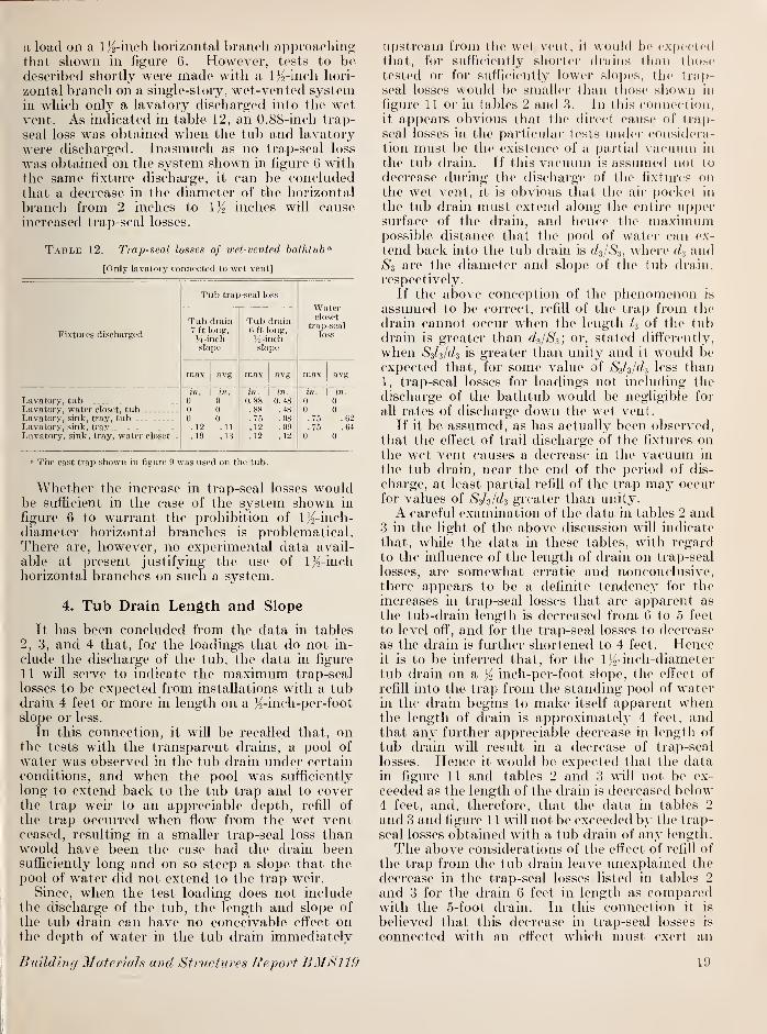
a load on a 1/2-inch horizontal branch appi'oaching
that shown in figure 6. However, t(>sts to bedescribed shortly were made with a 1/^-inch hori-
zontal branch on a single-story, wet-vented systemin which only a lavatory discharged into the wetvent. As indicated in table 12, an 0.88-inch trap-
seal loss was obtained when the tub and lavatory
were discharged. Inasmuch as no trap-seal loss
was obtained on the system shown in figure 6 withthe same fixture discharge, it can be concludedthat a decrease in the diameter of the horizontal
branch from 2 inches to Iji inches will causeincreased trap-seal losses.
T.^BLE 12. Trap-seal losses of wet-vented bathtub'^
[Only lavatory connected to wet vent]
Fixtures discharged
Tub trap-seal loss
Watercloset
trap-seal
loss
Tub drain7 ft long,
H-inchslope
Tub drainB ft long,
Ji-inchslope
max avg max avg max avg
Lavatory, tubLavatory, water closet, tub ,
Lavatory, sink, trav, tub_. . ... ..
Lavatory, sink, tray ..
Lavatory, sink, tray, water eloset..
in.
0n
0. 12
. 19
in.
0(1
0. 11
.13
in.
0. 88.88.75. 12. 12
in.
0. 48.48.08.09. 12
in.
0
0.75.76
0
in.
00
.62
.640
" The cast trap shown in figui'e 9 was used on the tub.
Wliether the increase in trap-seal losses wouldbe sufficient in the case of the system shown in
figure 6 to warrant the prohibition of l^-inch-diameter horizontal branches is problematical.There are, however, no experimental data avail-
able at present justifying the use of l)2-inch
horizontal branches on such a system.
4. Tub Drain Length and Slope
It has been concluded from the data in tables
2, 3, and 4 that, for the loadings that do not in-
clude the discharge of the tub, the data in figure
11 will serve to indicate the maximum trap-seal
losses to be expected from installations with a tubdrain 4 feet or more in length on a }^-inch-per-foot
slope or less.
In this connection, it will be recalled that, onthe tests with the transparent drains, a pool of
water was observed in the tub drain under certain
conditions, and when the pool was sufficiently
long to extend back to the tub trap and to coverthe trap weir to an appreciable depth, refill of
the trap occurred when flow from the wet ventceased, resulting in a smaller trap-seal loss thanwould have been the case had the drain beensufficiently long and on so steep a slope that thepool of water did not extend to the trap weir.
Since, when the test loading does not includethe discharge of the tub, the length and slope of
the tub drain can have no conceivable effect onthe depth of water in the tub drain immediately
upstream from the wet vent, it would be exper-ted
tliat, for sufliciently shorter drains lliaii those
tested or for sufficiently lower slopes, the trap-
seal losses would be smaller than tfiose shown in
figure 11 or in tables 2 and 3. In this connection,it appears obvious that the direct cause of trap-
seal losses in. the particular tests under considera-tion must be the existence of a partial vacuum in
the tub drain. If this vacuum is assumed not to
decrease during the discharge of tlie fixtures onthe wet vent, it is obvious that the air pocket in
the tub drain must extend along the entire uppersurface of the drain, and hence the maximumpossible distance that the pool of water can ex-
tend back into the tub drain is d^/S^, where andS3 are the diameter and slope of tlie tub drain,
respectively.
If the above conception of the phenomenon is
assumed to be correct, refill of the trap from the
drain cannot occur when the length 4 of the tubdrain is greater than d^/Si] or, stated differently,
when SzUldz is greater than unity and it would beexpected that, for some value of S-jl^/d^ less than
1, trap-seal losses for loadings not including the
discharge of the bathtub would be negligible for
all rates of discharge down the wet vent.
If it be assumed, as has actually been observed,
that the effect of trail discharge of the fixtures onthe wet vent causes a decrease in the vacuum in
the tub drain, near the end of the period of dis-
charge, at least partial refill of the trap may occurfor values of Sds/d^ greater than unity.
A careful examination of the data in tables 2 and3 in the light of the above discussion will indicate
that, while the data in these tables, with regardto the inffuence of the length of drain on trap-seal
losses, are somewhat erratic and nonconclusive,there appears to be a definite tendency for the
increases in trap-seal losses that are apparent as
the tub-drain length is decreased from 6 to 5 feet
to level off, and for the trap-seal losses to decrease
as the drain is further shortened to 4 feet. Henceit is to be inferred that, for the IJr inch-diametertub drain on a inch-per-foot slope, the effect of
refill into the trap from the standing pool of waterin the drain begins to make itself apparent whenthe length of drain is approximately 4 feet, andthat any further appreciable decrease in length of
tub drain will result in a decrease of trap-seal
losses. Hence it would be expected that the datain figure 11 and tables 2 and 3 will not be ex-
ceeded as the length of the drain is decreased below4 feet, and, therefore, that the data in tables 2
and 3 and figure 1 1 will not be exceeded by the trap-
seal losses obtained with a tub drain of any length.
The above considerations of the eff ect of refill of
the trap from the tub drain leave unexplained the
decrease in the trap-seal losses listed in tables 2
and 3 for the drain 6 feet in length as comparedwith the 5-foot drain. In this connection it is
believed that this decrease in trap-seal losses is
connected with an effect which must exert an
Building Materials mul Structures Report BMS119 19

increasing influence on trap-seal losses as the tubdrain is lengthened. The pressure reduction in
the tub drain is created b}^ the water flowing fromthe wet vent. For a given pressure reduction in
the tub drain, the volume of air to be evacuatedfrom a drain 6 feet long will be greater than for a
drain 5 feet in length, and hence the time required
for the pressure reduction in the tub drain to
reach equilibrium will be longer for the 6-foot
drain, assuming that the rate of evacuation is the
same in the two cases. If the duration of the
discharge through the wet vent is greater than the
time required for the pressure reduction in the
tub drain to reach equilibrium, this phenomenonwill have no effect on the trap-seal losses as the
drain is increased in length. However, for agiven duration of flow in the wet vent, it is obviousthat, as the di-ain length is increased, eventually a
point will be reached at which the time requiredto evacuate sufficient air from the tub drain so
that equilibrium exists will be greater than the
duration of flow from the fixtures on the wet vent.
Wlien this point is reached, it would be expectedthat any further increase in tub drain length wouldcause decreased trap-seal losses. It is believed
that the phenomenon described is the cause of the
decrease in trap-seal losses observed for the drain
6 feet in length as compared to the 5-foot drain.
Inasmuch as the trap-seal losses for the 4- and5-foot lengths of tub drain on a };^-m-per-foot slope
are substantially equal, it has been concludedthat, as the length of dram on a )^-inch slope is
increased beyond appro>imately 4 feet, refill fromthe drain into the trap does not occur. Since the
only possible effect, for the loading that does notinclude tlie discharge of the tub, of increasing the
slope of the tub drain is to decrease trap refill, it
foflows that the trap-seal losses in tables 2 and 3
and figure 1 1 will not be exceeded when the slope
of the tub drain is increased above Yo inch per foot.
In view of the above discussion regarding the
effect of tub drain length and slope, it may be con-
cluded, for the loading which does not include the
discharge of the tub, that the trap-seal losses of
tables 2 and 3 and figure 11 will not be exceededwith a tub drain of any length or slope.
In the case of loadings which include the dis-
charge of the bathtub, it appears equally clear
that the water surface in the tub drain will neverbe lower than would be the case for the loadingwhich does not include the discharge of the tub,
and hence it would be expected, as for the pre-
vious loading, that there exists some minimumvalue of Ss/s/f/a for which refill of the trap from thedrain is such that all loadings, irrespective of
whether the loading includes the discharge of the
tub, will produce negligible trap-seal losses. It
is interesting in this connection to note thatHunter [3] has proposed, in effect, that the slope,
diameter, and length of the unvented portion of
any fixture drain, whether wet, stack, or back-
vented, be limited so that the value of tSVs/r/s
shall not exceed unity.
5. Trap Dimensions
There are two methods by which a tub trap-seal loss due to negative pressure in the fixture
drain may occur. First, if the negative pressure,
expressed in inches of water, in the tub draincreated by the flow down the wet vent is less
than the depth of trap seal; then, assuming thatthe tub drain is sufficiently long and on a suffi-
ciently high slope to prevent refill of the trapfrom the drain, water will be drawn from thetrap until equilibrium occurs. When the flowin the wet vent ceases, the seal reduction in thetub trap will be one-half the magnitude of thenegative pressure head in the tub drain and is
independent of the depth of the trap seal and of
any other dimension of the trap, such as its
diameter. However, if the flow down the wetvent is large enough to cause a pressure reductionin the tub drain greater than the depth of the tubtrap seal, air will be bubbled from the atmos-phere through the trap into the tub drain. Thisprocess pumps water out of the tub trap and into
the drain and hence results in relatively large
trap-seal losses.
Consequently it is apparent, for a given pres-
sure reduction in the tub drain, that, if the depthof the tub trap seal is greater than the pressure
reduction in the drain, a decrease in depth of
trap seal will have no effect on the tub trap-seal
losses until a point is reached at which the depthof trap seal is equal to the pressure reductionin the drain. Any further reduction in depth of
trap seal will cause a rapid increase in trap-seal
losses. Hence the effect of increasing the depthof tub trap seal from a value less than the pressure
reduction in the drain to a value greater will be,
in general, to decrease trap-seal losses substan-tially. And the effect of increasing the depthof tub trap seal, when it is at all times greater
than the negative pressure in the tub drain, will
be nil.
In the tests reported here, the depth of tubtrap seal was 2 inches or more, and the adoptedcriterion of satisfactory performance was a trap-
seal reduction of 1 inch. A trap-seal reduction of
1 inch corresponds to a negative pressure in the
tub drain of 2 inches. Hence, the particular
tests on which the conclusions as to the adequacyof wet venting have been based were made withloadings which produced negative pressures in
the tub drain equal to or less than the depth of
trap seal. It is apparent, therefore, that the
conclusions expressed in this report for traps withdepths of seal of 2 inches would not be changedby increasing the depth of trap seal.
From the discussion above on the effect of
change in tub trap-seal depths on tub trap-seal
losses, it is evident that a change in tub-trap
20 Wet Venting of PhimMng Fixtures

diameter coiikl have no effecl on tul) trap-seal
losses, as long as these losses ai-(> less than 1 inch,
which, as has been stated before, has been adopt(Hi
in this report as the criterion of satisfactoj'y trap
performance. Foi- this reason it is apparentthat the conclusions expressed regarding wetventing apply with equal force to tub-trap diam-eters of any size.
For seal losses greater than approximately 1
inch in a trap with a depth of seal of 2 inches,
air will be drawn tlii'ough the trap, as noted pre-
viously, and, when this condition arises, the diam-eter of the tub trap undoubtedly has some effect
on the amount of trap-seal reduction. Thisproblem was not investigated, but it would beexpected that a decrease in tub-trap diameterwould cause greater trap-seal losses.
From the preceding discussion on the effect of
changing the tub trap dimensions, it would beexpected that, for trap-seal losses of approximately1 inch or less, the cast and tubing traps shown in
figures 9 and 10 would give the same results,
whereas for the larger trap-seal losses, the cast
trap, owing to its smaller depth of trap seal and its
smaller diameter, would give the greater trap-seal
losses. Figures 11, 12, and 13 show this to be thecase.
6. Effect on the Trap- Seal Losses of a Wet-Vented Bathtub of Increasing the Diam-eters of the Lavatory and CombinationFixture Drains
Consid(>r first the loading which does not includethe discharge of the bathtub. The tub trap-seal
loss, h, under the assumed conditions will dependonly on the pressure, p, in the tub drain. Thispressure, however, depends on a number of
characteristics of the system—the length l-i, slope
Sz, and diameter (I3 of the tub drain, the volumerate of fiow through the wet vent, the pressure
Pi at the base of the wet vent, the diameter di of
the wet vent, and possibly the velocity Vi at thebase of the wet vent, and the diameter ^4, theslope S-2, and the length L of the horizontal branch.In turn, pi and i\ depend on certain additionalcharacteristics of the system, such as the diametersf/4 and f/5 of the combination fixture drain and thelavatory drain, respectively, and the length /, of
the wet vent. In addition they also depend onthe acceleration of gravity. The roughness of thepipe walls will also have some slight effect, but this
will not be important because the lengths involvedare short.
Equation 1 is the formal expression of thestatements made in the preceding paragraph.The pressures, p and pi, and the velocity do notappear in the right member of the equation, since
they depend, to a first approximation at least, onlyon quantities that are shown in the right member.
h^MO, (U, (k, (h, (h, U, I2, h, S2, S,, (I). (1)
This e(|uatioii contains 12 physical or
geometrical (juantities that can i)e expressed in
teims of two physical dimensions lenglli andtime—and it follows from tlie theory of dinien-
sional analysis thai it can be i-ewritten in terms of
12 — 2 = ]0 (liniensi()nless variables. Th<' exact
form of some of these var'iables is in pai-t optional
with us, and in these cases we use oui- physicalintuition oi' our past experience to form theparticular combinations that will be useful. Werewrite eq 1 as follows:
A r Q (/, (/, f/| f/, (U (l\ o ~|
bn\!<l(h <k di dr, li I2 h J
We are concerned here only with the eU'ect onthe trap-seal losses of changes in c/4 and r/-. Asidefrom this, the geometrical characteristics of the
system will remain constant, and hence we caneliminate from consideration the variables, c/|/c/2,
dxllu d-ilk, di/(:,, S2, and Si. Equation 2 thensimplifies to
d'Jgd, (h d,]h/di= 4)
One further simplification can be made, owingto the fact that we do not need to consider di
and dr, simultaneously, but only one at a time,
depending on which fixture is producing the flow,
Q. Hence we shall eliminate one of the twodiameter ratios and arbitrarily refer to the oneunder consideration as di. Equation 3 thenbecomes
A_f [ Q_ , A" (4)
which is the final form of the equation we shall
use to study the effect of changing the fixture
drain diameter. This equation is identical witheq 3 of the earlier paper on stack venting [1].
In the paper referred to [1], it was shown that
an increase in d^, which amounts to decreasing
the ratio djdi, has the effect of decreasing the
trap-seal loss h, or the relative trap-seal loss h/di
of stack-vented fixtures. Since a change in djdican, for a given 0, affect the trap-seal losses only
through the resulting eff'ect on the velocities andpressures in the wet vent or stack, and since the
basic phenomena governing the velocities andpressures in a vertical stack and in a wet vent are
essentially the same, it would be expected that a
decrease in di/di, as was the case with stack-
vented fixtures, would cause, for a given value of
0/d^^gdi, a decrease in the trap-seal losses of wet-
vented fixtures. However, the value of Qld\^,gdi
does not remain constant as d^ is increased, owingto the fact that an increase in d^ causes an in-
crease in Q, the discharge of the fixtures con-
nected to the wet vent ; and the data shown in
figure 11 indicate that an increase in Q wiU
Buihl'uKj MateriuJs. and Structures Report BMS119 21

ordinarily be accompanied by an increase in h,
the trap-seal loss of wet-vented fixtures. There-
fore, in the absence of specific data on the effect
of an increase in fixture drain diameters, it can
only be concluded that, if such an increase in
fixture drain diameters causes an increase in trap-
seal losses, the increase will be due_to an increase
in the value of the term, QJdl-yjgdx, and will not
exceed those shown by the data in figure 11 byusing the increased Q resulting from an increase
in di as the argument.
The data in figure 11 and table 2 for the cast
trap have been replotted in figure 18, using the
dimensionless variables developed above. It will
be observed from table 2 that some of the dataplotted in figures 11 and 18 are for flow from the
combination fixture alone, while other dataplotted from these figures are for flows from boththe lavatory and combination flxture. It will beobserved from both figures 11 and 18 that, for
1.21 1 1 1 r
o'—O h CD—I ' " 1
05 10 15 20 25 30
Q
df \/d| g
Figure 18. Dimensionless plot of wet venting data for test
loadings not including the bathtub.
Symbol
Diameter of
wet ventinches d,
dt
dx
di
dl di
d.
Nomi-nal
Actual
do
o2
l.fil
2. 070. 781.00
1.001. 50
1. 161.29
1.291.29
the range of flows tested, there is little apparentdifference in the test results between flows intro-
duced through the iM-inch-diameter lavatorydrain and the l^-inch combination fixture drain.These limited experimental data on the effect of
increasing the diameter of the fixture drainsintroducing water to the wet vent thus are inagreement with the conclusion expressed abovethat the trap-seal losses caused by increasing thediameter of the lavatory drain to lli inches orincreasing the diameter of the combination fix-
ture drain to 2 inches will not exceed thoseshown in figures 11 and 18 for the proper value
of 0 or pidisj'gd,.It will be observed in figure 18 that, for the
range of variables tested, the data for the 2-inch-diameter wet vent approximate fairly closely thedata for the 1/9 inch wet vent. Inasmuch as thedesign or test loads developed in section V-4-aare such that no extrapolation of these data for
either the IK or 2-inch-diameter wet vent is
necessar3^ the curve in figure 18 may be safel}!-
used as a design curve for either or l}2-inch-
diameter lavatory drains or with 1)2- or 2-inch-diameter sink or combination fixture drains. Theuse of a l}2-inch-diameter drain will increase therate of discharge from the lavatory by approxi-mately 3 gallons per minute. From table 1 thedesign loading proposed in section V-4-a becomes38.8 gallons per minute (13.6+ 25.2) for a lavatoryflow rate of 13.6 gallons per minute, which yields
a value for 0/d!l^/gdi of 2.32 for 1}^ -inch-diameterwet vent, and by reference to figure 18, it may beconcluded that a value of h/di of 0.5, or a trap-seal
loss of 0.80 inch for a nominal 1 Jo-inch wet vent,
would not be exceeded. This trap-seal loss is less
than the permissible value of 1 inch adopted in
this report and hence is satisfactory.
In table 13 are given rates of discharge for acombination fixture with a drain 2 inches in diam-eter and 2 feet long on a slope of inch per foot.
Assuming that the lavatory drain is 1^2 inches in
diameter and that consequently the lavatory hasa rate of discharge of 13.6 gallons per minute, it is
apparent from table 13 that the greatest dischargeobtainable for any two fixtures on the wet vent is
41.2 gallons per minute, which yields a value of
Q/dl^/gdi of 1.30 for a 2-inch-diameter wet vent.
T.\BLE 13. Rates of discharge of combination fixture withdrain 2 inches in diameter "
Fixtures dischargedEate of
flow
Sink—basket strainer.. . .
Sink—flat strainer
Qpm18.527.622.330. .3
36.0
Tray...Sink and tray—basket strainer..
Sink and trav—flat strainer . . .
n The fixture drain was 2 feet in length and had aslope of U inch per foot.
22 Wet Venting of Plumhing Fixtures

Reference to figure 18 shows that such a vahic of
Qldi\gdi will yield a trap-seal loss substantially
below 1 inch.
It may be concluded, therefore, that the in-
crease in diameter of the lavatory drain to l}^
inches or the increase in the diameter of the com-bination fixture drain to 2 inches will not yield
trap-seal losses in excess of the 1-inch seal loss
adopted as the dividing line between satisfactory
and unsatisfactory trap performance for these
tests.
The above discussion of the effect of increasing
the diameter of the lavatory or combinationfixture drain has been confined to a test loading
which does not include the discharge of the bath-
tub. It is obvious, however, that the inclusion of
the discharge of the tub in the test loading wouldin no way alter the above conclusions.
The data in table 6 for the loading, including
the discharge of the tub, have been replotted in
figure 19, using the dimensionless variables devel-
oped above. The length of the tub drains usedwas 4 feet with the 1 ^2-inch-diameter wet vent and5 feet with the 2-inch-diameter wet vent. Thecorresponding values of SJ^/di are 1.24 and 1.21,
respectively, {Sj^Y: inch per foot, and f/i= 1.61
and 2.07 inches, respectively). Again, as the
only possible effect of increasing di and rf, will be
to increase the value of Q/dl^gdi and to increase
the pressure in the tub drain for a given value of
Q/di-\lgdi, it is concluded that the increase in
h/di because of an increase in d^ and ds will be dueto the resulting increase in the value of the term,
Qld\-\jgdx, and will not exceed the value of hjdi
obtained from the data in figure 19 by using the
increased value of Q/d'i\(idi as the argument.
7. Diameter of Bathtub Drain
The great majority of the tests of this investi-
gation were macle w^ith 1 K-inch-diameter bathtubdrains. However, as 2-inch-diameter tub drains
are installed occasionally, a few of the tests weremade with the larger diameter bathtub drain.
The results of some of these tests are shown in
table 14. It will be observed that the eft'ect of
increasing the diameter of the tub drain is to
decrease the tub trap-seal losses.
Table 14. Effect of tub drain diameter on trap-seal losses
losses of a wet-vented bathtub
Tub trap-seal loss
Flow throughwet-vent U2-inch- 2-inch-
diameter diametertub drain tub drain
Gpm In. In.n.9 0.0 0.015.3 .38 .027.2 .38 .0
d|9
Fir.uRE 19. Dimensionless plot of wet venting data fortest loadings including the discharge of the bathtub.
SymbolDiameterof wetvent
rfi
dz di di
di
d.
S3Z3
di
Inches
O 0.78 1.00 1. 16 1. 29 1.242 1.00 1.50 1.29 1. 29 1.21
The data in table 14 were obtained from a sys-
tem with a Uo-inch-diameter wet vent, lavatory,
and sink drain, and a 2-inch-diameter horizontalbranch. The tub drain was 4 feet long and wason a slope of K inch per foot.
In obtaining the data given in table 14, onlythe diameter of the bathtub drain was increasecl.
In figure 20 are shown similar data for anothersystem in which both the bathtub and the combi-nation fixture drain diameters were increased from
20 30 40 50
FLOW THROUGH WET VENT, GPM
60
Figure 20. Effect of tub and combination fixture draindiameters on trap-seal losses.
A. li-fj-inch-diami'ter drains on tub and combination fixture, B. 2-inch-
diameter drains on tub and combination fixture.
Buihihifj Materials and Structures Report BMS119 23

1% to 2 inches. It wiW again be observed that the
increase in tub-ch-ain-diameter decreases trap-
seal losses.
Under these circumstances it is to be concluded
that the data presented previously for l}2-inch
bathtub drain diameters can be applied with atleast equal safety to installations in which thediameter of the bathtub drain is 2 inches.
VII. Tests on a Single- Story Wet-Vented System With Only a Lavatory Connectedto the Wet Vent
The test system for this series of tests is shownin figure 21. The stack and 18 feet of building-
drain were made of 3-inch-diameter transparenttubing. The remainder of the system was madeof conventional pipe materials. The slope of the
building drain was }i inch per foot.
In table 15 are given tub and water-closet trap-
seal losses for a tub drain 7 feet long laid on a/2-inch-per-foot slope. It will be noted from figure
21 that the water closet is stack-vented, so that
in reality the bathroom group of fixtures is par-
tially stack-vented and partially wet-vented. Forthis reason, water-closet trap-seal losses occur, andthese have been listed in table 15. When the tubwas among the fixtures discharged, the other fix-
tures making up the test loading were dischargedin such a manner that their flow began 3 secondsprior to the end of the period of tub flow. In the
case of the lavatory, the only fixture on the wetvent, the timing of its discharge with respect to
the end of the tub discharge was found to influence
greatly the amount of trap-seal loss obtained. Forexample, when the tub and lavatory discharges
endecl simultaneously, the average seal loss of 10
tests was 0.02 inch, whereas with the sequence of
discharges noted above the average trap-seal loss
was 0.48 inch.
It will be noted from table 15 that none of thetrap-seal losses observed were in excess of the
adopted permissible trap-seal loss, and that hencethe wet-vented system in figure 21 may be con-sidered to be adequately vented for the lengthsand slopes of drains tested here—that is, for tubdrain lengths and slopes up to a maximum lengthof 6 feet when laid on a /2-inch-per-foot slope, andup to a maximum length of 7 feet when laid on a}^-inch slope.
Under these circumstances it is apparent thatthe conclusions derived from the tests made of
the system shown in figure 6 may be applied withat least equal safety to the system being consideredhere, in which only the lavatory is connected to
the wet vent, and the horizontal branch is IJo
inches in diameter.The tests reported in table 15 were made with
a house trap in the building drain. These tests
were repeated without a house trap installed in
the building drain, and in no case was there anyappi-eciable or significant difference in the test
J FIXTU
3-IN DIAMETER STACK
COMBINATIONRE
-1^- IN. OIAMETER
-WET VENT
-1^ - DIAMETER
f DIAMETER /W C HORIZONTAL BRANCH Jg^
I"l8'-0"
3-IN, DIAMETER TRANSPARENT TUBINS
8- IN. DIAMETER STREET SEWER
4-IN DIAMETER FIBRE PIPE
<>Si70-0
<j
Figure 21. Test system.
results. It may be concluded, therefore, thatany service condition, such as a house trap or asubmerged house sewer, which causes an increase
in the positive pressures in the stack will notcause a single-story wet-vented system to operateless satisfactorily.
Table 15. Bathiub and water closet trap-seal losses forthe wet-vented system shown in figure 21
Fixtures discharged
Lavatory and tubLavatory, tub, andwatei closet
Lavatory, sink, trayand tub
Lavatory, sink, andtray
Lavatory, sink, tray,and water closet
Trap-seal losses '
Bathtub
Tub drain7 ft. longon \i in.
per ft.
slope
Tub drainG ft. longon So in.
per ft.
slope
avg
Water closet
Tub drain7 ft. longon Vi in.
per ft.
slope
avg
Tub drain6 ft. longon 'j in.
per ft.
slope
. 57
.58
> The data represent the ma-\imuin and average trap-seal losses observedin 5 consecutive tests made under identical conditions. The lK>-inch cast
trap shown in figure 9 was used on the tub.
24 Wet Venting of Plumhing Fixtures

VIII. Tests on Two- Story, Duplex, Wet-Vented System
These tests were made on the system shown in
figure 22. The greater part of the tests weremade with all of the system except the building
sewer made of transparent plastic tubing andfittings. As was the case with, the other systemstested, the transparent fittings used were identical,
3-IN. DIAMETER STACK
Figure 22. Tivo-story, duplex, wet-venled system.
within close tolerances, with conventional soil
pipe fittings. The fixtures used in these tests
were identical with those used on the other sys-
tems tested, and the data in table 1 for rates of
flow from fixtures apply to this system as well as
to the other two systems.In figure 23 are given tub trap-seal losses for
this system for various lengths of tub drain . Thedata in figure 23 are all for tub drain slopes of Kinch per foot. The lavatories were discharged so
that the flow from the tubs and lavatories endedsimultaneously. The two tubs and the two lava-tories were discharged, since this loading wasfound to produce the greatest tub trap-seal losses.
The data plotted in flgure 23 represent the maxi-mum trap-seal loss observed in 10 consecutivetest runs made under identical conditions.
It is apparent from this flgure that, for the plug-
discharge of the flxtures on this system, the trap-seal losses are independent of the length of thehorizontal branch, as was the case with the othertwo systems tested. It will also be noted thatthe effect of the two diflerent types of fittings
used to connect the lavatory drains to the wetvent was negligible. Of particular interest in
this figure is the fact that the trap-seal losses for
the \Vi- and 2-inch diameter wet vents were for
all practical purposes identical. Since the rate of
dischai'ge of two lavatories approximates the I'ate
of How of a sink, it is evi(h'nt from a comparisonof these (hita with. th.()S(> of tal)les 5 and (5 that the
volume rate of How down the wet vent is not the
only varial)le connected with flow conditions in
th.e wet vent wliich aftect the wet venting phe-nomena. The discharge of the hi vatoiics was in-
troduced to the wet vent througli 1 '4-inch-diam-
eter drains, whereas the sink cUscharge was intro-
duced through a l/2-inch,-(Uameter drain. As hasbeen stated previously, the velocity with whichwater is introduced to a vei'tical stack has animportant efl'ect on the trap-seal losses of stack-
vented flxture traps below the point of water en-
trance, and it is to be inferred from this fact that
the entrance velocity of the water introduced into
a vertical stack or wet vent would have an impor-tant effect on the pressures in the stack or wet
LENGTH OF BATHTUB DRAIN IN FEET
FinuRE 23. Trap-seal losses of a two-story, duplex, wet-
vented system.
Both tubs and lavatories discharged
Symbol
Length of
horizontalbranch
Diameter of
wet vent
Lavatoryvent
fitting
ft. in.
• 2. 58 1. 5 Long-turn.2. 58 1. 5 Short-turn.
H 2.58 2.0 Do.
0 6.0 1. 5 Long-turn.
A 6.0 1. 5 Short-turn.
6.0 2.0 Do.
vent, and hence would affect the trap-seal losses
of a wet-vented flxture.
In addition, the duration of flow from the lava-
tories is approximately 10 seconds, while the
duration of flow from a sink is approximately 15
seconds, and the data in flgure 5 have shown that
the duration of flow, under certain circumstances,
materiaUy afl'ects the trap-seal losses of wet-ventedfixtures. It is probable that these dift'erences be-
tween lavatory and sink discharge into the wetvent account for the fact that the 2-inch-diameter
wet vent yields smaller trap-seal losses than the
Biiildiiif/ Materials <ni<i Sttacta res Report BM8119 25

1/2-incli wet vent for sink flow and the same loss
for the discharge of two lavatories.
Test data for a constant rate of flow from thelavatories are given in figure 24, a condition whichmight occur when the lavatory is used by merelydrawing water from the faucets. The data for
flow rates of 6 gallons per minute were obtainedby flow from one lavatory, whereas in the tests
0 ' HOAOdOvD bAei 1
3 4 5 6 7
LENGTH OF BATHTUB DRAIN IN FEET
Figure 24. Effect of length of bathtub drain'^ on wet venting
of bathtub trap.
Two-story duplex system. Continuous flow from lavatories.
Horizontaldistance
between wetvent and
3-inch stackDiameterof wetvent
Lavatory ventfitting
Initial depthof water in
bathtubs
Rate of
flow fromlavatory
2 ft.
7 in.6 ft.
oA
in.
V/22
Lonp-turn T-VShort-turn T...Short-turn
] 2i4 in. in one tub> and 6 in. in
1 other tub.
gpm
110.8
CAH 2
Long-turn T-YShort-turn T...Short-turn T...
1 2J^in, in one tub> and 6 in. in
J other tub 16.0
AHi
2
Long-turn T-YShort-turn T...Short-turn
{214 in. in each
1tub } 6.0
aVS
VA1)42
Long-turn T-YShort-turn T,..Short-turn T...
[214 in. in each
I
tub. } 10.8
a Slope of bathtub drain, inch per foot.
with a flow rate of 10.8 gallons per minute, 5.4gallons per minute was flowing from each lavatory.These particular flow rates were chosen from theexperimentally determined fact that a flow rate ofapproximately 5 gallons per minute is about themaximum that can be used in a lavatory in this
manner without excessive and undesirable splash-ing.
Preliminary tests with continuous flow from thelavatories showed that under certain conditions agreater reduction in trap seal was obtained whenthe tubs did not end their discharge at the sametime. The most convenient method of regulatingthe length of time between the end of flow in onetub and the end of flow in the other was to fill thetubs to different depths and then pull the rubberstoppers simultaneously. It was found that asufficiently long period between tub dischargeswas given by filling one tub to a depth of 2}^ inchesand the other a depth of 6 inches. However, themaximum trap-seal loss does not always occurwhen the tub discharges end a minute or so apart.Therefore, tests were also made with both tubsfilled to the same depth.
It was also determined in preliminary tests thatthe initial depth of water in the bathtubs had noeffect on the amount of trap-seal loss, providedthe initial depth was greater than a certainminimum.The initial depths of water listed in figure 24,
therefore, have no significance except to indicate
that the discharge of the tubs either endedsimultaneously or that they ended approximatelyone minute apart.
As has been stated, the data in figures 23 and 24are for tub drain slopes of Yo inch per foot. Testswere also made with tub drains 7 feet long on a/4-inch-per-foot slope. In no case, with the tubdrain slope of '4 inch were any trap-seal losses
observed.
From the data in figures 23 and 24 it is evidentthat the adopted permissible trap-seal loss of
1 inch will not be exceeded on the two-story,
duplex system provided the lengths of tub drains
do not exceed 6 feet for a slope of inch per foot
and do not exceed 7 feet (the maximum lengthtested) for a slope of % inch per foot.
It is clear that the conclusions regarding per-
missible lengths of wet-vented tub drains drawnfrom the test data obtained with the systemshown in figure 6 may be applied with at least
equal safety to wet-vented fixtures on the top
floor of a two-story duplex system.
26 Wet Venting of Plumhing Firtures

IX, Wet-Vented Fixtures on the Lower Floors of Multistory Buildings
All the venting tests made in connection withthis project have been made either on a one-story
installation or on the top floor of a two-story
installation. There were no fixtures discharging;
into the stack on floors above the wet-ventedfixtures being tested. For this reason the test
results reported here apply directly only to the
top floor of any structure, where the primaryfunction of fixture vents is to prevent self-
siphonage. In multistory stacks pressures andvacuum are of course created in the stack at the
lower floor levels by the discharge of fixtures
on the upper floors. In such cases the fixture
vents will be required to relieve stack pressures
and vacua, as well as to prevent self-siphonage.
Since the effect of using wet vents instead of
back vents is to reduce the number of ventsavailable on the lower floors for relieving stackpressures and vacuums, it is apparent that the
indiscriminate substitution of a single wet ventto a group of fixtures for the purpose of replacing
several back vents may lead lo undcsiiableresults on the lower floor, uidess other means, suchas the installation of a relief or yoke vent, are
provided to control stack pressures and vacuums.However, in this connection it may again ]m
pointed out that Hunter [2] has shown lliat the
wet-vented group of fixtures shown in figure 4, a,
may be installed safely on the first floor of a two-story building in which a single l)atlu'oom groupof flxtures, in adtlition to a kitchen sink or com-bination fixture, are located on the upper floor;
and in a later publication [3] prepared in theform of a code by the Subcommittee on Plumbing,Central Housing Committee on Research, Designand Construction, to which Hunter was technical
adviser, this type of installation, or that of figure
6, is permitted on the lower floor without a back-vent for the water closet, provided the fixtures onthe upper floor do not exceed a single batlu'oomgroup and a kitchen sink or combination fixture.
X. Conclusions
From the test data presented it is concludedthat the wet venting of one or two bathtub traps
on the highset branch interval of systems such as
those shown in figures 6, 21, and 22 is an adequateand satisfactory method of venting, provided:
1. The slope, S3, and the length, I3, of the tubdrains and the diameter di of the wet vent are suchthat the value of the quantity Ssls/di does not ex-
ceed unity;
2. The diameter of the horizontal branch is notless than I/2 inches when one lavatory connectsto the vent and not less than 2 inches when twolavatories, or a lavatory and a kitchen sink, or alavatory and a combination fixture connect to thewet vent; and
3. The fixtures on the wet vent connect to this
vent at the same level.
In connection with conclusion 1 above, it will be
recalled that, in computing the values of SJ.s/di, S3
should be expressed in feet per foot or inches per
inch and that ^3 and di should be expressed in thesame units of length.
Acknowledgment is made to the Housing andHome Finance Agency for its support of theinvestigation reported in this paper. The authorsalso express their appreciation of the cooperationof the members of the Uniform Plumbing CodeCommittee sponsored by the Housing and HomeFinance Agency, and especially that of the Chair-man of that Committee, Vincent T. Manas, in
formulating the problem investigated and in offer-
ing many practical suggestions.
The authors also express their appreciation for
the many valuable practical suggestions made byEd Monteath, who acted as Industrial Adviser to
the Bureau in connection with the investigation.
The experimental work was carried out by MarionR. Brockman, Anthony L. Lembeck, and VictorBrame, Jr., and the authors are indebted to these
experimenters for their careful and thorough work
XI. References
[1] John L. French, Stack venting of plumbing fixtures
NBS Building Materials and Structures Report
BMS118 (1950).
[2] Recommended minimum requirements for plumbing in
dwellings and similar buildings, NBS BH2 (1924).
[3] Plumbing manual, Report of the Subcommittee on
Plumbing, Central Housing Committee on Research
Design, and Construction, NBS Building Materials
and Structures Report BMS66 (1940).
O
Building Alateriah md Structures Report BMSI19
[4] Emergency plumbing standards for defense housing,Division of Defense Housing Coordination, Execu-tive Office of the President, Office for EmergencyManagement (1942).
[5] Recommended minimum requirements for plumbing,NBS BH13, (1932).
[6] R. B. Hunter, Methods of estimating loads in plumbingsvstems, NBS Building Materials and StructuresReport BMS65 (1940).
Washington, March 23, 1950.
2T


BUILDING MATERIALS AND STRUCTURES REPORTS
[Continued fronn cover page ii]
BMS32 Structural Properties of Two Brick-Coiicrete-Block Wall Constructions and a Con-crete-Block Wall Construction Sponsored by the National Concrete MasonryAssociation 15^.
BMS33 Plastic Calking Materials 15ji
BMS34 Performance Test of Floor Coverings for Use in Low-Cost Housing: Part 1 15^BMS35 Stability of Sheathing Papers as Determined by Accelerated Aging *
BMS36 Structural Properties of Wood-Frame Wall, Partition, Floor, and Roof Construc-tions With "Red Stripe" Lath Sponsored by The Weston Paper and Manufac-turing Co lOji
BMS37 Structural Properties of "Palisade Homes" Constructions for Walls, Partitions, andFloors, Sponsored by Palisade Homes *
BMS38 Structural Properties of Two "Dunstone" Wall Constructions Sponsored by theW. E. Dunn Manufacturing Co 10^
BMS39 Structural Properties of a Wall Construction of "Pfeifer Units" Sponsored by theWisconsin Units Co 10^
BMS40 Structural Properties of a Wall Construction of "Knap Concrete Wall Units" Spon-sored by Knap America, Inc 15$i
BMS41 Effect of Heating and Cooling on the Permeability of Masonry Walls *
BMS42 Structural Properties of Wood-Frame Wall and Partition Construction with "Celotex"Insulating Boards Sponsored by The Celotex Corporation 15jS
BMS43 Performance Test of Floor Coverings for Use in Low-Cost Housing: Part 2 15^BMS44 Surface Treatment of Steel Prior to Painting 10^BMS45 Air Lifiltration Through Windows 15^BMS46 Structural Properties of "Scott-Bilt" Prefabricated Sheet-Steel Constructions for
Walls, Floors, and Roofs Sponsored by The Globe-Wernicke Co 10^BMS47 Structural Properties of Prefabricated Wood-Frame Constructions for Walls, Par-
titions, and Floors Sponsored by American Houses, Lie 20^BMS48 Structural Properties of "Precision-Built" Frame Wall and Partition Constructions
Sponsored by the Homasote Co 15^BMS49 Metallic Roofing for Low-Cost House Construction 20^BMS50 Stability of Fiber Building Boards as Determined by Accelerated Aging lO^i
BMS51 Structural Properties of "Tilecrete Type A" Floor Construction Sponsored by theTilecrete Co 10^
BMS52 Effect of Ceiling Insulation Upon Summer Comfort 15fS
BMS53 Structural Properties of a Masonry Wall Construction of "Munlock Dry Wall Brick"Sponsored by the Munlock Engineering Co 10^
BMS54 Effect of Soot on the Rating of an Oil-Fired Heating Boiler 10^BMS55 Effects of Wetting and Drying on the Permeability of Masonry Walls 10^BMS56 A Survey of Humidities in Residences 10^BMS57 Roofing in the United States—Results of a Questionnaire *
BMS58 Strength of Soft-Soldered Joints in Copper Tubing 10^BMS59 Properties of Adhesives for Floor Coverings 15^BMS60 Strength, Absorption, and Resistance to Laboratory Freezing and Thawing of Building
Bricks Produced in the United States 30^BMS61 Structural Properties of Two Nonreinforced Monolithic Concrete Wall Constructions.- 100BMS62 Structural Properties of a Precast Joist Concrete Floor Construction Sponsored by
the Portland Cement Association 100BMS63 Moisture Condensation in Building Walls . 150BMS64 Solar Heating of Various Surfaces 100BMS65 Methods of Estimating Loads in Plumbing Systems 150BMS66 Plumbing Manual 350BMS67 Structural Properties of "Mu-Steel" Prefabricated Sheet-Steel Constructions for Walls,
Partitions, Floors, and Roofs, Sponsored by Herman A. Mugler 150BMS68 Performance Test for Floor Coverings for Use in Low-Cost Housing: Part 3 200BMS69 Stability of Fiber Sheathing Boards as Determined by Accelerated Aging 100BMS7G Asphalt-Prepared Roll Roofings and Shingles 200BMS71 Fire Tests of Wood- and Metal-Framed Partitions 200BMS72 Structural Properties of "Precision-Built, Jr." Prefabricated Wood-Frame Wall Con-
struction Sponsored by the Homasote Co__ 100BMS73 Indentation Characteristics of Floor Coverings 100BMS74 Structural and Heat-Transfer Properties of "U. S. S. Panelbilt" Prefabricated Sheet-
Steel Constructions for Walls, Partitions, and Roofs Sponsored by the TennesseeCoal, Iron & Railroad Co 200
BMS75 Survey of Roofing Materials in the North Central States 150BMS76 Effect of Outdoor Exposure on the Water Permeability of Masonry Walls 150BMS77 Properties and Performance of Fiber Tile Boards : 100BMS78 Structural, Heat-Transfer, and Water-Permeability Properties of Five Earth-Wall
Constructions 250BMS79 Water-Distributing Systems for Buildings 200BMS80 Performance Test of Floor Coverings for Use in Low-Cost Housing: Part 4 150BMS81 Field Inspectors' Check List for Building Constructions (cloth cover, 5 x 7}i inches) 200
•Out of print.
[List continued on cover page iv]

BUILDING MATEBIALS AxND STRUCTURES REPORTS
[Continued from cover page iii]
BMS82 Water Permeability of Walls Built of Masonry Units 25fS
BMS83 Strength of Sleeve Joints in Copper Tubing Made With Various Lead-Base Solders 15^BMS84 Survey of Roofing Materials in the South Central States 15^BMS85 Dimensional Changes of Floor Coverings With Changes in Relative Humidity and
Temperature lOfi
BMS86 Structural, Heat-Transfer, and Water-Permeability Properties of "Speedbrik" WallConstruction Sponsored by the General Shale Products Corporation 15^
BMS87 A Method for Developing Specifications for Building Construction—Report of Sub-committee on Specifications of the Central Housing Committee on Research,Design, and Construction 15fi
BMS88 Recommended Building Code Requirements for New Dwelling Construction WithSpecial Reference to War Housing *
BMS89 Structural Properties of "Precision-Built, Jr." (Second Construction) PrefabricatedWood-Frame Wall Construction Sponsored by the Homasote Co 15^
BMS90 Structural Properties of "PHC" Prefabricated Wood-Frame Constructions for Walls,Floors, and Roofs Sponsored by the PHC Housing Corporation 15^
BMS91 A Glossary of Housing Terms 15^BMS92 Fire-Resistance Classifications of Building Constructions 30fS
BMS93 Accumulation of Moisture in Walls of Frame Construction During Winter Exposure-. lOji
BMS94 Water Permeability and Weathering Resistance of Stucco-Faced, Gunite-Faced, and"Knap Concrete-Unit" Walls 15jS
BMS95 Tests of Cement-Water Paints and Other Waterproofings for Unit-Masonry Walls 25^BMS96 Properties of a Porous Concrete of Cement and Uniform-Sized Gravel lOfi
BMS97 Experimental Dry-Wall Construction With Fiber Insulating Board 10^BMS98 Physical Properties of Terrazzo Aggregates 15ji
BMS99 Structural and Heat-Transfer Properties of "Multiple Box-Girder Plywood Panels" forWalls, Floors, and Roofs 15fi
BMSlOO Relative Shpperiness of Floor and Deck Surfaces 10^BMSlOl Strength and Resistance to Corrosion of Ties for Cavity Walls lOfi
BMS102 Painting Steel 10^BMS103 Measurements of Heat Losses From Slab Floors 15^BMS104 Structural Properties of Prefabricated Plywood Lightweight Constructions for Walls,
Partitions, Floors, and Roofs Sponsored by the Douglas Fir Plywood Association. _ 30{i
BMS105 Paint Manual with particular reference to Federal Specifications $1. 00BMS106 Laboratory Observations of Condensation in Wall Specimens *
BMS107 Building Code Requirements for New Dwelling Construction *
BMS108 Temperature Distribution in a Test Bungalow With Various Heating Devices lOfS
BMS109 Strength of Houses: Application of Engineering Principles to Structural Design $L 50BMSllO Paints for Exterior Masonry Walls 15fi
BMSlll Performance of a Coal-Fired Boiler Converted to Oil 15^BMS112 Properties of Some Lightweight-Aggregate Concretes With and Without an Air-
entraining Admixture lOjS
BMS113 Fire Resistance of Structural Clay Tile Partitions 15^BMS114 Temperature in a Test Bungalow With Some Radiant and Jacketed Space Heaters 25^BMS115 A Study of a Baseboard Convector Heating System in a Test Bungalow 15^BMS116 Preparation and Revision of Building Codes 15^S
BMS117 Fire Resistance of Walls of Lightweight Aggregate Concrete Masonry Units 20^BMS118 Stack Venting of Plumbing Fixtures 15ji
BMS119 Wet Venting of Plumbing Fixtures 20^
•Out of print.