Embed Size (px)
Citation preview

Westinghouse Non-Proprietary Class 3
Westinghouse Electric Company LLC
1000 Westinghouse Drive Cranberry Township, PA 16066
Copyright © 2011 Westinghouse Electric Company LLC
All Rights Reserved
UK AP1000 Integrated Waste Strategy
UKP-GW-GL-054, Revision 1

Revision History UK AP1000 Integrated Waste Strategy
UKP-GW-GL-054 ii Revision 1
REVISION HISTORY
Revision Description of Change
0 Initial Submittal
1 Revised in-line with the latest Regulatory Observations, Technical Queries and DCP EPS-GW-GEE-001.
Addresses new Westinghouse trademark guidelines.
Trademark Notice
AP1000 is a trademark or registered trademark in the United States of Westinghouse Electric Company LLC, its subsidiaries and/or its affiliates. This mark may be used and/or registered in other countries throughout the world. All rights reserved. Unauthorized use is strictly prohibited. Other names may be trademarks of their respective owners.

Table of Contents UK AP1000 Integrated Waste Strategy
UKP-GW-GL-054 iii Revision 1
TABLE OF CONTENTS
Section Title Page
REVISION HISTORY ................................................................................................................................. ii
LIST OF TABLES ........................................................................................................................................ v
LIST OF FIGURES ..................................................................................................................................... vi
1. EXECUTIVE SUMMARY ............................................................................................................. 1
2. INTRODUCTION ........................................................................................................................... 3
2.1 Generic AP1000 NPP Site Description .............................................................................. 3
2.2 Waste Systems Overview ................................................................................................... 7
3. WASTE MANAGEMENT POLICY, ORGANISATION, AND ARRANGEMENTS ................ 20
3.1 Statement of Policies and Principles ................................................................................. 20
3.2 Waste Management Organisation ..................................................................................... 24
3.3 Waste Management Arrangements ................................................................................... 25
4. FORMULATION OF INTEGRATED WASTE MANAGEMENT STRATEGY ........................ 29
4.1 Overview .......................................................................................................................... 29
4.2 Methodology for Strategic Options Study ........................................................................ 29
4.3 Site Prioritisation Logic .................................................................................................... 29
4.4 Waste Management Constraints and Dependencies ......................................................... 29
4.5 Site End Points and Contaminated Land .......................................................................... 30
4.6 Assumptions, Exclusions, Risks, and Opportunities ........................................................ 30
4.7 Stakeholder Engagement .................................................................................................. 30
5. OVERVIEW OF SITE WASTE STRATEGY .............................................................................. 33
5.1 Overview .......................................................................................................................... 33
5.2 Milestones ......................................................................................................................... 33
6. INTEGRATED WASTE MANAGEMENT STRATEGY ............................................................ 35
6.1 Overview .......................................................................................................................... 35
6.2 Radioactive Waste Management Cases ............................................................................ 35

Table of Contents UK AP1000 Integrated Waste Strategy
UKP-GW-GL-054 iv Revision 1
6.3 Conventional Solid Waste Strategy .................................................................................. 35
6.4 Conventional Gaseous Strategy ........................................................................................ 35
6.5 Conventional Liquid Strategy ........................................................................................... 36
6.6 Low Level Solid Radioactive Waste Strategy .................................................................. 40
6.7 Intermediate Level Waste Strategy ................................................................................... 42
6.8 Spent Fuel Strategy ........................................................................................................... 42
6.9 Decommissioning Waste .................................................................................................. 42
7. AREAS REQUIRING FURTHER DEVELOPMENT AND ACTION PLAN ............................. 55
8. CONCLUSIONS ........................................................................................................................... 56
9. GLOSSARY .................................................................................................................................. 57
10. REFERENCES .............................................................................................................................. 67

Table of Contents UK AP1000 Integrated Waste Strategy
UKP-GW-GL-054 v Revision 1
LIST OF TABLES
Table 2-1 AP1000 NPP Generic Site Key .................................................................................................. 16
Table 4-1 Assumptions and Exclusions ...................................................................................................... 32
Table 9-1 Glossary of Terms ...................................................................................................................... 57

Table of Contents UK AP1000 Integrated Waste Strategy
UKP-GW-GL-054 vi Revision 1
LIST OF FIGURES
Figure 2-1. AP1000 NPP Main Buildings ................................................................................................. 17
Figure 2-2. AP1000 NPP Generic Site Layout .......................................................................................... 18
Figure 2-3. Operational Milestones ........................................................................................................... 19
Figure 3-1. Waste Management Hierarchy ................................................................................................ 26
Figure 3-2. Minimisation of Equipment and Materials .............................................................................. 26
Figure 3-3. Nuclear BAT Management Factors for Optimisation of Releases from Nuclear Facilities .... 27
Figure 3-4. Nuclear BAT Management Factors and AP1000 NPP Features ............................................. 28
Figure 5-1. Milestones Applicable to Waste Strategy ............................................................................... 34
Figure 6-1. Conventional Solid Waste Route ............................................................................................ 47
Figure 6-2. Condensate Polishing System Resin Routes ........................................................................... 48
Figure 6-3. Solid Low Level Waste Routes ............................................................................................... 49
Figure 6-4. Gaseous Route ......................................................................................................................... 50
Figure 6-5. Liquid Waste Route ................................................................................................................ 50
Figure 6-6. Low Level Waste Oil Route .................................................................................................... 51
Figure 6-7. Solid Intermediate Level Waste Route ................................................................................... 52
Figure 6-8. Spent Fuel Route ..................................................................................................................... 53
Figure 6-9. Decommissioning Intermediate Level Waste Route ............................................................... 54

1. Executive Summary UK AP1000 Integrated Waste Strategy
UKP-GW-GL-054 1 Revision 1
1. EXECUTIVE SUMMARY
This Integrated Waste Strategy (IWS) document has been prepared for the Generic Design Assessment (GDA) of the Westinghouse AP1000TM Nuclear Power Plant (NPP). This is to assist in the identification of the strategic issues relating to waste management and to guide the development of waste management plans.
The generic nature of the current assessment phase means that certain issues that depend upon particular site details cannot be fully developed, and it is recognized that these aspects will need to be addressed in detail during site-specific works once site details become known. In these cases, the key features that will influence the detailed development have been identified. It is expected that developments of this IWS to suit a specific site will be undertaken by the utility operators of the AP1000 NPP.
This document follows the format specified in the Nuclear Decommissioning Authority (NDA) documents “Specification for the Content and Format of a Site Integrated Waste Strategy Document,” ENG01 [Ref. 1], “Companion Document to Integrated Waste Strategy Specification,” ENG02 [Ref. 2].
Using the guidance in [Ref. 2], this IWS:
Provides a coordinated approach to waste management and stakeholder engagement:
Provide an overarching framework for delivery of best practice in waste avoidance, minimization, and management
Provide a coherent basis for communicating waste plans and their rationale to allow participation in decision making by key stakeholders
Link waste management to planning issues such as development consent and spatial planning
Makes the most effective use of existing waste management facilities:
Supporting waste management and, hence, decommissioning and cleanup through development of site
Identify and prioritize “critical” facilities or services required to support waste management and decommissioning/cleanup activities
Provides value for money:
Supporting effective planning of decommissioning and waste management
Enabling clear thinking across sites to develop an integrated waste management strategy
Support improvements in the efficiency and coordination of waste avoidance, minimization, and management activities
Identify risks, opportunities, uncertainties, and other relevant issues relating to waste management and how they will be managed
1. Executive Summary UK AP1000 Integrated Waste Strategy
UKP-GW-GL-054 2 Revision 1
Clarify ownership of waste issues and relevant decisions and ensure that interfaces between sites are clearly and consistently defined
Focus research and development efforts to resolve waste issues and ensure the availability of necessary technology and skills
Provide an overarching management strategy for delivery of best practice in dealing with waste issues
Also, to be fully optimised [Ref. 2], this IWS:
Defines a clear waste management policy, and the necessary waste management arrangements and organization, to give effect to this policy is in place
Delivers compliance with relevant legal obligations (for example, license conditions and instruments, authorizations, permits, consents)
Demonstrates that it is based on a systematic and integrated framework for the consideration of potential waste management options
Demonstrates that this framework for consideration of potential waste management options seeks to identify synergies available from considering waste management options at site as well as project, process or plant level
Demonstrates that this framework for consideration of potential waste management options transparently takes account of the full range of relevant health, safety, environmental, and security (including safeguards) principles and criteria (for example, those within the Environment Agency [EA] and Scottish Environmental Protection Agency [SEPA] guidance on best practicable environmental option [BPEO])
Demonstrates that this framework for consideration of potential waste management options considers current and potential future interfaces with other sites where relevant
Demonstrates that the framework for optimisation incorporates a systematic approach to stakeholder engagement on waste management options and other waste issues
Demonstrates the existence of an optimised strategy in line with best practice and the waste hierarchy for the management of all the wastes over the whole lifecycle of the site
Describes the key reasons for selection of particular waste management options within the description of the sites strategy for each waste stream

2. Introduction UK AP1000 Integrated Waste Strategy
UKP-GW-GL-054 3 Revision 1
2. INTRODUCTION
Westinghouse Electric Company LLC (Westinghouse) is seeking approval to have an AP1000 simplified passive advanced light water reactor electricity generating plant built in the United Kingdom (UK). The standard plant description is included in Chapter 1 of the “AP1000 European Design Control Document” [Ref. 3] (DCD). The AP1000 NPP design has been incorporated into the United States Nuclear Regulatory Commission’s (NRC’s) Design Certification Rule for the AP1000 NPP design, Section II.A of Appendix D to 10 CFR Part 52. However, UK regulations require other information on the AP1000 NPP to be submitted to the UK Environment Agency (EA), as well as other UK regulators.
This IWS relates to all wastes and all materials that could become waste, both radioactive and non-radioactive, arising from all stages of the site lifecycle including operational and decommissioning activities, as well as contaminated land management as appropriate. It is a companion document to the “UK AP1000 Environment Report” [Ref. 4] and the Radioactive Waste Management Case (RWMC) Evidence Reports for intermediate level waste (ILW) [Ref. 5] and high level waste (HLW) [Ref. 6].
This document has been prepared for the Generic Design Assessment (GDA), to assist in the identification of the strategic issues relating to waste management and to guide the development of waste management plans. The intent is that it is a living document, and it will be developed by the licensee to address the requirements of a specific site, to take account of changing site conditions, to address revisions to the regulatory framework, and to keep pace with the requirements for environmental and safety improvements throughout the site lifecycle.
2.1 Generic AP1000 NPP Site Description
2.1.1 Standard AP1000 NPP Buildings
The main buildings of a standard AP1000 NPP are shown in Figure 2-1. These comprise both seismically qualified and non-seismically qualified buildings, ancillary equipment, roadways, and access features. Descriptions of the AP1000 NPP buildings are in Chapter 1 of the DCD [Ref. 3] and Chapter 2 of the “UK AP1000 Environment Report” [Ref. 4] and are summarized in the following subsections.
2.1.1.1 Nuclear Island
The Nuclear Island consists of a number of buildings and structures all designed to meet seismic Category I structural requirements, and these are listed below:
The containment vessel is a high integrity freestanding steel structure with a wall thickness of 4.44cm and a diameter of 39.6m. The containment vessel prevents the uncontrolled release of radioactivity to the environment in the event of a significant fault.
The concrete shield building that surrounds the containment vessel is a cylindrical, reinforced concrete structure with a conical roof that supports the water storage tank and air diffuser (or chimney) of the passive containment cooling system. The shield building has an inner diameter of 43m, a height of 22m, and a wall thickness of 0.9m in the cylindrical section. The shield building provides an additional radiological barrier for radioactive systems and components within the containment vessel. It also provides protection for the containment vessel from external events.

2. Introduction UK AP1000 Integrated Waste Strategy
UKP-GW-GL-054 4 Revision 1
The auxiliary building houses the seismic Category I mechanical and electrical equipment located outside of the containment vessel. It shares a common foundation mat with the shield building. The auxiliary building provides protection for safety-related equipment against the consequences of internal and external events. The auxiliary building also houses the main control room, fuel handling and spent fuel handling area, mechanical equipment areas, liquid and gaseous radwaste areas, and main steam and feedwater isolation valve compartments.
2.1.1.2 Non-Nuclear Island Buildings
Listed below are the non-seismic buildings associated with the AP1000 NPP. These non-seismic Category I structures contain no safety-related equipment, but are designed for wind and seismic loads in accordance with the uniform building code. The foundation of each building is a reinforced concrete mat.
The annex building contains the main personnel entrance to the power generation complex. The building includes the health physics area, ancillary diesel generators and fuel supply, technical support centre, and various heating, ventilation and air conditioning (HVAC) systems.
The turbine building houses the main steam turbine, generator, and associated fluid and electrical systems. The makeup water purification system is also housed within this building.
The diesel generator building houses two diesel generators and their associated HVAC equipment.
The radwaste building contains facilities for processing and packaging various categories of solid low level waste (LLW) prior to processing.
2.1.1.3 Waste Treatment and Storage
In addition to the AP1000 NPP reactor related buildings and structures described above, there are also facilities (not shown in Figure 2-1) for the storage of solid HLW1, LLW, and ILW generated during the operation of the AP1000 NPP. The additional features relevant to waste management are included in Table 2-1 and further described in Section 2.2. A plan view of the generic AP1000 NPP site is shown in Figure 2-2, and a comparison with Figure 2-1 allows the location of additional facilities with respect to the main AP1000 NPP building to be readily appreciated.
Spent Fuel
The spent fuel system proposed for the generic site is a dry storage system and comprises:
flask loading equipment within the AP1000 NPP. suitable flask transportation vehicles and equipment. a seismically qualified below ground dry storage facility.
The flask handling equipment within the AP1000 NPP can accommodate a variety of flask types, and the spent fuel pool within the AP1000 NPP provides sufficient capacity for up to
1. Spent fuel is the only HLW arising from the AP1000 construction, operation, maintenance, and
decommissioning.

2. Introduction UK AP1000 Integrated Waste Strategy
UKP-GW-GL-054 5 Revision 1
18 years storage. The selection of the spent fuel storage system, therefore, can be deferred for a period to allow new techniques to be incorporated if appropriate.
The spent fuel may need to be stored until the end of this century. The spent fuel store could be used to retain spent fuel after the AP1000 NPP is decommissioned and until the national HLW repository becomes available.
ILW Store
The ILW store proposed for the generic site is a reinforced concrete structure that can be extended at appropriate intervals to suit new ILW arisings.
Initially, the ILW store will be 33m long, 13.5m wide, and 14m high (externally), and it has walls 1m thick.
The ILW store incorporates a receipt area with waste package assay equipment and a shielded vault serviced by a certified nuclear crane. Office and administration space and an equipment room housing HVAC and electrical and mechanical equipment are provided in an annex to the main store building.
Extensions to the store will be sized to suit future waste arisings, and they are expected to be added in 20-year increments. The ILW may need to be stored until the end of this century. The ILW store could be used to retain ILW after the AP1000 NPP is decommissioned and until the national ILW repository becomes available.
Radwaste Building
The radwaste building incorporates all of the facilities necessary to handle the solid LLW arisings from AP1000 NPP operations and maintenance. Facilities include:
radwaste sub-change (LLW processing area) waste sorting area (glove box enclosure). waste size reduction (glove box enclosure). waste decontamination (glove box enclosure). large item laydown area local HVAC facilities servicing the large item laydown area. low resolution gamma spectroscope (LRGS) for assaying LLW drums. clearance and exemption area in drum compactor.
The radwaste building incorporates a LLW processing room (‘Waste Accumulation Room’ #50351) used to process the LLW produced by the AP1000 NPP. The room contains sorting, size reduction and decontamination enclosures, an in-drum compactor and an area for working on large items. Access to this room is via a sub-change in the North-West corner, which also serves ‘Monitor Tanks Room A’ #50356 and ‘Monitor Tank Room B’ #50355. The buffer/marshalling area is located in the North-East corner of the room which can also be used to store LLW for which processing has been deferred, which could be because the LLW activity is at the higher end of the LLW range and a period of decay will provide handling benefits (e.g. dose reduction). This room is serviced by a dedicated pallet truck to mitigate the spread of contamination. Waste enters and exits the room via the East door into the ‘Mobile Systems Facility room #50350.

2. Introduction UK AP1000 Integrated Waste Strategy
UKP-GW-GL-054 6 Revision 1
The current position of the LRGS is in the ‘Mobile Systems Facility’, directly adjacent to the door leading into the LLW processing area ‘Waste Accumulation Room’. During site-specific detail design this position could change, or local shielding may be added if the area’s background radiation impedes the functionality of the LRGS.
Clean empty RWMD 3m3 boxes and drums, secondary containment vessels (SCVs) and 200liter drums are stored on the North and South walls of the ‘Mobile Systems Facility.’
LLW is sorted, processed (decontaminated and size reduced to the maximum extent reasonably practicable), packaged, and recorded. Full LLW drums are placed in HHISO containers, and these are shipped, possibly by way of the onsite LLW buffer store, to the national low level waste repository (LLWR).
The radwaste building also incorporates monitoring tanks associated with the liquid waste system. This system is described further in subsection 2.2.1.
There are three truck bays within the radwaste building, each complete with systems and equipment to allow the connection of mobile waste handling equipment. A shielded pipe trench to each of the truck bays is used to route liquid radwaste supply and return lines from the connections in the shielded pipe pit at the auxiliary building wall. For example, it might be necessary to deploy additional equipment to filter oil from the liquid waste system prior to processing by AP1000 NPP systems.
LLW Buffer Store
Under normal operation, once filled, the transport containers will be transferred directly off site to the nominated facility. The radwaste building will not provide temporary storage for full transport containers, other than the transport containers (HHISO or other) in the loading area. However, if the off-site facility is unable to accept waste for a period, it can be temporarily stored in either the LLW or the non-contaminated waste buffer stores.
Both the LLW buffer store and the non-contaminated buffer store are located directly South-West of the radwaste building. Figure 2-2 shows the AP1000 NPP generic site layout, Items 28 and 29 are the non-active and LLW buffer store respectively and Item 5 is the radwaste building.
The buffer store areas comprise of a concrete hardstanding with steel framed over canopy. They are designed for half height ISO (HHISO) containers that have been filled in the radwaste building. They will also be capable of storing other various transport containers, conforming to the conditions for acceptance (CfA) of off-site facilities. Standard handling machinery (fork truck) will be used to move the containers from the radwaste building to the buffer stores. The combined capacity for HHISO containers within each buffer store provides for up to two years waste arisings.
2.1.2 Main AP1000 NPP Systems
Major systems of the AP1000 NPP are as follows:
Reactor coolant system Steam and power conversion systems Auxiliary fluid systems Electrical and control systems
2. Introduction UK AP1000 Integrated Waste Strategy
UKP-GW-GL-054 7 Revision 1
More detailed AP1000 NPP facility information is available in Chapter 1 of the DCD [Ref. 3]. General arrangements of the main buildings are presented in Section 1.2 of the DCD. Other details of the facility features and systems are described within the following DCD chapters:
Chapter 3 – design of structures, components, equipment, and systems
Chapter 4 – reactor
Chapter 5 – reactor coolant system (including steam generators)
Chapter 9 – auxiliary systems, including spent fuel storage and handling, water systems, equipment and floor drainage systems (subsection 9.3.5), and ventilation system (Section 9.4)
Chapter 10 – steam generator blowdown system (subsection 10.4.8)
Chapter 11 of the DCD describes the standard AP1000 NPP radioactive waste management systems, including liquid waste management system (Section 11.2), gaseous waste management system (Section 11.3), and solid waste management (Section 11.4). Radiation monitoring is also described (Section 11.5).
Liquid waste management systems include demineralisation, degassing, and filtration. The gaseous waste management system uses activated carbon beds to delay the gas flow permitting time for radioactive decay.
Solid waste is collected in the auxiliary building and radwaste building. Summary information on the liquid radwaste system (WLS), WGS, chemical and volume control system, and spent fuel pond cooling system is presented in Section 2.2. Additional detail can be found in the DCD [Ref. 3].
2.2 Waste Systems Overview
The AP1000 NPP systems that are most relevant to waste are described below.
2.2.1 Liquid Radwaste System
The WLS is designed to control, collect, process, handle, store, and release liquid radioactive waste generated as the result of plant operation. The WLS is designed to process, or store, radioactively contaminated wastes of four major categories:
Borated, reactor-grade water collected via the chemical and volume control system or via the reactor coolant drain tank, and routed to the effluent holdup tanks. This water is the principal input in terms of volume and activity.
Floor drains and other wastes collected by various building floor drains and sumps, and routed to the waste holdup tanks. They potentially have high suspended solid contents.

2. Introduction UK AP1000 Integrated Waste Strategy
UKP-GW-GL-054 8 Revision 1
Detergent wastes coming from the plant hot sinks and showers, and some cleanup and decontamination processes, and routed to the chemical waste tank. They have low concentrations of radioactivity and contain soaps and detergents not compatible with the ion exchange resins. If their activity is low enough, they can be discharged without processing, otherwise they will be treated.
Chemical wastes collected from the laboratory and other relatively small volume sources. These wastes are generated at a low rate.
Located in the nuclear island auxiliary building, the AP1000 NPP WLS input first passes through a degasifier before storage in the effluent holdup tanks. The contents of the effluent holdup tanks may be:
Recirculated and sampled.
Recycled through the degasifier for further gas stripping.
Returned to the reactor coolant system via the chemical and volume control system makeup pumps.
Directed to the monitor tanks for discharge.
Passed through an upstream filter followed by four ion exchange resin vessels in series. Any of these vessels can be manually bypassed and the order of the last two can be interchanged to provide complete usage of the ion exchange resin. The second, third, and fourth beds are in identical ion exchange vessels, which are selectively loaded with resin, depending on prevailing plant conditions. Under normal conditions, all of the ion exchange beds are in use. Reconfiguration of the ion exchange vessels and associated manual valves are under administrative control to prevent an advertent bypass of the demineraliser or sub-optimal treatment of waste.
The monitor tanks located in the radwaste building are used to store processed water. This water is sampled, and if necessary, returned to a waste holdup tank or recirculated directly through the filters and ion exchangers. Waste water meeting the discharge limits is discharged to the circulating water blowdown through a radiation detector that stops the discharge if high radiation is detected.
2.2.2 Gaseous Radwaste System
The gaseous radwaste system (WGS) is designed to perform on an intermittent basis the following major functions:
Collect radioactive or hydrogen bearing gaseous wastes
Process and discharge the waste gas while keeping offsite releases of radioactivity within acceptable limits
2. Introduction UK AP1000 Integrated Waste Strategy
UKP-GW-GL-054 9 Revision 1
WGS inputs are as follows:
Reactor coolant system degassing: during dilutions, borations, and reactor coolant system degassing before shutdown, the chemical and volume control system letdown flow is diverted to the WLS degasifier. The WLS degasifier discharge is then the largest input to the WGS.
WLS reactor coolant drain tank degassing: the reactor coolant drain tank contents are also degassed by the WLS degasifier, and the resulting gas is then routed to the WGS. When enough gas has naturally come out of the reactor coolant drain tank contents, the tank is also vented to the WGS.
The AP1000 NPP WGS is a once-through, ambient temperature, activated carbon delay system. The system includes a gas cooler, a moisture separator, an activated carbon-filled guard bed, and two activated carbon-filled delay beds. The radioactive fission gases entering the system are carried by hydrogen and nitrogen gas that pass through the system tanks. When the WGS is in use, its operation is passive, using the pressure provided by the influent sources to drive the waste gas through the system. These influents successively pass through:
The gas cooler, where they are cooled to about 4ºC by the chilled water system.
The moisture separator, which removes the moisture from the cooled gas. The collected water is periodically discharged automatically.
A guard bed, which protects the delay beds from abnormal moisture carryover or chemical contaminants.
Two delay beds in series where xenon and krypton are delayed by a dynamic adsorption process. Radioactive decay of the fission gases during the delay period significantly reduces the radioactivity of the gas flow leaving the system.
A radiation monitor before discharge to the ventilation exhaust duct.
2.2.3 Solid Radwaste System
The solid radwaste system (WSS) is designed to collect and accumulate spent ion exchange resins and deep bed filtration media, spent filter cartridges, dry active wastes, and mixed wastes generated as a result of normal plant operation, including anticipated operational occurrences. The system is located in the auxiliary and radwaste buildings. Processing and packaging of wastes are by:
A mobile solid ILW encapsulation plant deployed in the auxiliary building rail car bay. This handles ILW resins and filter cartridges.
LLW sorting, packaging and processing (compaction) facilities for LLW located in the radwaste building.
Deployment and connection of other mobile equipment using the mobile equipment bays within the radwaste building to process certain wastes; for example, oil and chemical.
The packaged waste is stored in the radwaste building, the LLW buffer store and the ILW Store until it is shipped offsite to national waste repositories.

2. Introduction UK AP1000 Integrated Waste Strategy
UKP-GW-GL-054 10 Revision 1
The use of mobile systems for the processing functions permits the use of the latest technology and avoids the equipment obsolescence problems experienced with installed radwaste processing equipment. The most appropriate best available technique (BAT) and efficient systems may be used as they become available.
This system does not handle large, radioactive waste materials such as core components or low level radioactive process wastes from the plant’s secondary cycle. Core components are expected to be retained within containment until decommissioning and then handled along with other ILW decommissioning wastes.
The solid waste management system is designed to meet the following objectives:
The transfer and retention of spent radioactive ion exchange resins and deep bed filtration media from the various ion exchangers and filters in the liquid waste processing, chemical and volume control, and spent fuel cooling systems
Provide the means to change out, transport, sample, and accumulate filter cartridges from liquid systems in a manner that minimizes radiation exposure of personnel and spread of contamination
Provide the means to sample, and transfer spent resins and filtration media to a mobile encapsulation plant for dewatering and solidification
Provide the means to accumulate spent filters from the plant heating, ventilation, and air-conditioning systems
Provide the means to segregate solid wastes (trash) by radioactivity level and to temporarily store the wastes
Provide the means to store radioactive hazardous (mixed) wastes
Provide the means to segregate clean wastes originating in the radiologically controlled area
Provide the means to store packaged wastes for in the event of delay or disruption of offsite shipping to the national waste repositories (up to 2 years for LLW, up to the end of this century for ILW)
Provide the space and support services required for mobile processing systems that could be used to reduce the volume of and package radioactive solid wastes for offsite shipment and disposal
Provide the means to return liquid radwaste to the WLS for subsequent processing and monitored discharge
The WSS collects and stores radioactive wastes within shielding to maintain radiation exposure to plant operation and maintenance personnel as low as is reasonably practicable (ALARP). Design features incorporated to maintain exposures ALARP includes remote and semi-remote operations, automatic resin transport line flushing, and shielding of components, piping, and containers holding radioactive materials. Access to the solid waste storage areas is controlled, to minimize inadvertent personnel exposure, by suitable barriers, such as heavy storage cask covers and locked or key-card-operated doors or gates.

2. Introduction UK AP1000 Integrated Waste Strategy
UKP-GW-GL-054 11 Revision 1
LLW disposal containers are selected that conform to the current CfA for the national low level waste repository. ILW waste packages are Radioactive Waste Management Directorate (RWMD) compliant 3m3 boxes and drums, which meet the CfA for the future national intermediate level waste repository.
The WSS is designed to minimize, to the extent practicable, contamination of the facility and the environment, facilitate decommissioning, and minimize, to the extent practicable, the generation of radioactive waste. This is done through appropriate selection of design technology for the overall AP1000 NPP design as well as the system, plus incorporating the ability to update the system to use the best available technology throughout the life of the plant.
2.2.4 Spent Fuel
After spent fuel is removed from the reactor, it will be stored in the fuel storage pond (subsection 9.1.2 of the DCD). Because spent fuel will not be reprocessed, a facility for dry spent fuel storage for the operational period of the plant and beyond is being designed. This is compatible with national policy.
Each step in the management of spent fuel will be compatible with all other steps, including storage, disposal, handling, and onsite and offsite transport. The spent fuel will be safely disposed, at appropriate times and in appropriate ways. For a specific site, AP1000 NPP operators may further develop this aspect of the IWS and the spent fuel management arrangements to account for progress in the development of the national HLW repository and associated strategy.
2.2.4.1 Fuel Description and International Experience
The fuel developed for the AP1000 NPP is based on the current 17x17 robust fuel assembly (RFA) fuel in use worldwide. The 17x17 RFA has the following characteristics:
Largest product line in Westinghouse-built reactors
Basis for fuel supplied to EDF reactors (both 900 MWe and 1,300 MWe)
Successful experience (as of September 2007)
– Over 9,594 assemblies and 158 reloads operated in 35 units worldwide since initial operation in 1997; worldwide experience includes 14 units in the United States, 20 units in Europe, and 1 in Asia.
– Burnups approaching 62 GWD/MTU lead rod design limit
– Excellent performance
2.2.4.2 Fuel Operational Regime
The proposed operational regime will help to support the design intention of minimizing spent fuel. The reference AP1000 NPP equilibrium cycle design is an 18-month cycle. The cycle is based on an assumed 97 percent capacity factor and a 21-day refueling outage. This provides a cycle length of approximately 510 effective full power days.
This equilibrium cycle feeds (and discharges) approximately 64 fuel assemblies every 18 months. On the average, this means that approximately 43 assemblies per year are

2. Introduction UK AP1000 Integrated Waste Strategy
UKP-GW-GL-054 12 Revision 1
discharged and stored in the spent fuel pool storage area. The spent fuel pond racks can hold 889 fuel assemblies (approximately 18 years of spent fuel) before dry cask storage is required.
2.2.4.3 Quantification of Discharge of Spent Fuel
As previously mentioned, the reference 18-month cycle for AP1000 NPP will discharge on the average 43 fuel assemblies every year (64 assemblies every 18 months). Utilities can operate an AP1000 NPP on many different cycle lengths (for example, annual versus 18-month cycles) as best meets their operational needs. Fuel utilization is typically optimized when the plant operates in stable, equilibrium cycle lengths. Large variations in cycle length, such as a transition to 18-month cycles from annual cycles or vice-versa, tend to under use fuel.
2.2.4.4 Spent Fuel Pond and Storage Racks Descriptions
The AP1000 NPP spent fuel pond contains three Region 1 rack modules, five Region 2 rack modules, and five individual defective fuel assembly storage cells. The total storage capacity is 889 locations.
The Region 1 modules are all 9x9 arrays of storage cells. They are designated Modules A1, A2, and A3. Note that the Region 1 modules are located along the west wall of the AP1000 NPP spent fuel pond.
There are four Region 2 modules, which are 12x11 arrays of storage cells. They are designated Modules B1, B2, B3, and B4. These modules are located along the east wall of the AP1000 NPP spent fuel pond.
There is a single 12x10 (-7) Region 2 module. It is designated Module C1. (Note that the term “12x10 (-7)” means a 12x10 array that is missing seven storage cells. The seven storage cells removed from the 12x10 array provide space for the five defective fuel assembly storage cells.)
The five defective fuel assembly storage cells are located between the Region 2, 12x10 (-7) module and the west wall of the AP1000 NPP spent fuel pond.
2.2.5 Dry Spent Fuel Storage
The AP1000 NPP spent fuel is stored in a dry store, based around the Holtec International HI-STORM 100U system. Because the AP1000 NPP spent fuel pond provides for 18 years of storage, several years after start of operation, an AP1000 NPP operator may choose to utilise an alternative spent fuel storage system according to the outcome of a future BAT assessment and this aspect of the IWS can be developed to account for the selected storage scheme. In addition, the national HLW repository may become available before the storage within the spent fuel pond is full. In this case, an onsite spent fuel store may not be required.
The HI-STORM 100U System consists of three primary components:
HI-STORM 100U underground vertical ventilated module (VVM) Multi-purpose canister (MPC), which contains the spent fuel assemblies HI-TRAC transfer cask, which hold the MPC during loading operations
The MPC and HI-TRAC in the HI-STORM 100U System are 100 percent identical to those in the Holtec aboveground system that has been in use for several years.

2. Introduction UK AP1000 Integrated Waste Strategy
UKP-GW-GL-054 13 Revision 1
2.2.6 Spent Fuel Pond Cooling System
The new and spent fuel storage facilities are located within the auxiliary building area. The main system associated with these facilities is the spent fuel pond cooling system.
The spent fuel pond cooling system consists of two similar independent trains of equipment. One train is continuously cooling and purifying the spent fuel pond while the other train is available for all the other main functions of the systems: water transfers, in-containment refueling water storage tank purification, or as backup to the operating train of equipment. The major functions of the spent fuel pond cooling system and the corresponding modes of operation are as follows:
Spent fuel pond cooling: removes heat from the water in the spent fuel pond during operation to maintain the pond water temperature within acceptable limits. The spent fuel pond cooling system is designed to remove decay heat which is generated by stored fuel assemblies from the water in the spent fuel pond. This is done by pumping the high temperature water from within the fuel pond through a heat exchanger, and then returning the water to the pond.
Spent fuel pond purification: removes radioactive corrosion products, fission product ions, and dust to maintain low spent fuel pond activity levels during plant operation and to maintain water clarity during all modes. Two mixed bed type demineralisers are provided to maintain spent fuel pond purity, each one sized to accept the maximum purification flow from its respective cooling train. Downstream of the demineralisers in the purification branch lines, a spent fuel pond filter is provided to collect small particles and resin fines.
Refueling cavity purification: provides purification of the refueling cavity during refueling operations.
In-containment refueling water storage tank purification: provides purification and cooling of the in-containment refueling water storage tank during normal operation.
Water transfers – transfer water between:
– The in-containment refueling water storage tank and the refueling cavity during refueling operations.
– The passive containment cooling water storage tank and the spent fuel pond to provide sufficient makeup to the spent fuel pond.
– The fuel transfer canal to the cask loading pit. Water that is normally stored in the fuel transfer canal and can be sent to the cask loading pit and vice versa.
2.2.7 Chemical and Volume Control System
The chemical and volume control system is designed to perform the following major functions:
Purification: maintain reactor coolant system fluid purity and activity level
Reactor coolant system inventory control and makeup: maintain the required coolant inventory in the reactor coolant system and pressuriser water level during operations

2. Introduction UK AP1000 Integrated Waste Strategy
UKP-GW-GL-054 14 Revision 1
Chemical shim and chemical control: manage the reactor coolant chemistry and pH by controlling the concentration of boron and lithium hydroxide
Oxygen control: maintain the proper level of dissolved hydrogen in the reactor coolant during start-up and operations
Filling and pressure testing the reactor coolant system
Borated makeup to auxiliary equipment: provide makeup water to the primary side systems that require borated reactor grade water
Pressuriser auxiliary spray: provide pressuriser auxiliary spray water for depressurisation
The ionic purification loop of the chemical and volume control system is inside the containment, and it uses the head from the reactor coolant pumps as the motive force for the purification flow. During power operations, fluid is continuously circulated through one of the two purification loops (one for operation and one as backup) that are sized to provide a minimum of one fuel cycle of service without change out. Each loop is composed of the following:
Mixed bed demineraliser removing ionic corrosion products and ionic fission products
Cation bed demineraliser used intermittently to control the concentration of lithium-7 (pH control)
Filter provided downstream of the demineraliser collecting particulates and resin fines
Once processed, the flow returns to the suction of a reactor coolant pump. During shutdown when the reactor coolant pumps are stopped, the normal residual heat removal system provides the motive force.
Radioactive gaseous purification is performed if radioactive gas removal is required during operation because of high fuel defects. The chemical and volume control system is diverted to the WLS using the chemical and volume control system makeup pumps as the motive force. The flow is routed outside of containment through the WLS degasifier, the effluent holdup tanks, and then back to the reactor coolant system.
During shutdown, the removal of radioactive gas and hydrogen is necessary to avoid extending the maintenance and refueling outages. The degassing process is accomplished by operating the chemical and volume control system in the open loop configuration.
One makeup filter is provided to collect particulates in the makeup stream, such as boric acid storage tank sediment.
2.2.8 Current and Future Status
This IWS document is a preliminary document suitable for a generic site. It is expected that a utility operator of an AP1000 NPP will further develop this document and associated detailed procedures as required for a specific site.

2. Introduction UK AP1000 Integrated Waste Strategy
UKP-GW-GL-054 15 Revision 1
2.2.9 Operational Milestones
The currently assumed timescales and major milestones for an AP1000 NPP on a generic site are shown in Figure 2-3. A start date is dependent on the selection of a specific site, and for this reason, actual dates are not shown.
2.2.10 Current Assumed Final End Point
It is currently assumed that following the end of power generation operations, life extension notwithstanding, that the AP1000 NPP and associated facilities will be decommissioned and dismantled and the site restored to its original state. The spent fuel and ILW storage facilities may be retained for a further period until the national HLW and ILW repositories become available. The ILW decommissioning waste would be sent to the onsite ILW store until a repository is available. Following transfer of the spent fuel and ILW to the national repository, the onsite storage facilities will be decommissioned and dismantled. The final site end point is a fully cleared site suitable for de-licensing. Getting to this final state will incorporate periods of institutional control; for example, during operation of the stores and following decommissioning and dismantlement of store facilities prior to de-licensing.
2.2.11 Site Objectives
A series of high level site objectives will be developed by the utility operators of an AP1000 NPP for a specific site. However, the site objectives shall typically address:
The minimization of operational hazards from all site operations.
The safe and cost effective storage, handling, and treatment of wastes from all aspects of plant operation.
The eventual de-licensing of the site following decommissioning and remediation.

2. I
ntr
odu
ctio
n
UK
AP
1000
In
tegr
ated
Was
te S
trat
egy
UK
P-G
W-G
L-0
54
16
Rev
isio
n 1
Tabl
e 2-
1
AP
1000
NP
P G
EN
ER
IC S
ITE
KE
Y
Item
D
escr
ipti
on
Item
D
escr
ipti
on
Item
D
escr
ipti
on
1 C
onta
inm
ent/
Shi
eld
Bui
ldin
g 12
C
onde
nsat
e St
orag
e Ta
nk
23
Spen
t Fue
l Sto
re E
xten
sion
1 (
40 y
ears
st
orag
e)(1
)
2 T
urbi
ne B
uild
ing
13
Die
sel G
ener
ator
Fue
l Oil
Sto
rage
Tan
ks
24
Futu
re S
pent
Fue
l Sto
re E
xten
sion
2 (
60 y
ears
st
orag
e)(1
)
3 A
nnex
Bui
ldin
g 14
D
emin
eral
ised
Wat
er
25
ILW
Sto
re E
xten
sion
1 (
40 y
ears
sto
rage
)(1)
4 A
uxil
iary
Bui
ldin
g 15
B
oric
Aci
d St
orag
e Ta
nk
26
ILW
sto
re E
xten
sion
2 (
60 y
ears
sto
rage
)(1)
5 R
adw
aste
Bui
ldin
g(1)
16
Hyd
roge
n St
orag
e Ta
nk A
rea
27
D
ecom
mis
sion
ing
Faci
lity
(fu
ture
)(1)
6 P
lant
Ent
ranc
e
17
Tur
bine
Bui
ldin
g L
aydo
wn
Are
a
28
Stor
age
Are
a F
or N
on-R
adio
acti
ve W
aste
(1)
7 D
iese
l Gen
erat
or B
uild
ing
18
W
aste
Wat
er R
eten
tion
Bas
in
29
Stor
age
Are
a F
or L
ow L
evel
Was
te(1
)
8 F
ire
Wat
er/C
lear
wel
l Sto
rage
Tan
k
19
Pas
sive
Con
tain
men
t Coo
ling
Anc
illar
y W
ater
St
orag
e Ta
nk
30
Are
a Fo
r C
ontr
acto
r C
ompo
und
(Wor
ksho
ps/P
erso
nnel
Cab
ins)
9 F
ire
Wat
er S
tora
ge T
ank
20
Die
sel D
rive
n Fi
re P
ump/
Enc
losu
re
31
Are
a Fo
r St
orag
e O
f L
arge
Rad
ioac
tive
Mai
nten
ance
Com
pone
nts(1
)
10
Tra
nsfo
rmer
Are
a
21
ILW
Sto
re (
20 y
ears
)(1)
11
Sw
itch
Yar
d 22
S
pent
Fue
l Sto
re (
20 y
ears
)(1)
Not
es:
1.
Fea
ture
s re
leva
nt to
was
te h
andl
ing.

2. I
ntr
odu
ctio
n
UK
AP
1000
In
tegr
ated
Was
te S
trat
egy
UK
P-G
W-G
L-0
54
17
Rev
isio
n 1
Fig
ure
2-1
. A
P10
00 N
PP
Mai
n B
uil
din
gs

2. Introduction UK AP1000 Integrated Waste Strategy
UKP-GW-GL-054 18 Revision 1
Figure 2-2. AP1000 NPP Generic Site Layout

2. Introduction UK AP1000 Integrated Waste Strategy
UKP-GW-GL-054 19 Revision 1
Design
Construction
Commissioning
Operation
Decommission
5 (5)
3 (8)
2 (10)
60 (70)
22 (92)
Time
Figure 2-3. Operational Milestones

3. Waste Management Policy, Organisation and Arrangements UK AP1000 Integrated Waste Strategy
UKP-GW-GL-054 20 Revision 1
3. WASTE MANAGEMENT POLICY, ORGANISATION, AND ARRANGEMENTS
3.1 Statement of Policies and Principles
3.1.1 Waste Management Hierarchy and Relationship to an AP1000 NPP
The requirements of the waste management hierarchy, Figure 3-1, are inherent in many aspects of the AP1000 NPP design. The AP1000 NPP design is an evolutionary progression from preceding advanced passive and earlier reactor designs. The development of the AP1000 NPP design is described in “The Genesis and Process of the AP1000 Design” [Ref. 7].
The basic AP1000 NPP design principles minimise the creation of radioactive waste during operations and decommissioning. AP1000 NPP was designed to have fewer valves, pipes, and other components (Figure 3-2), so less waste will be generated during maintenance activities (repair and replacement). Also, less waste mass will be generated during decommissioning. As discussed in the ‘UK AP1000 NPP Decommissioning Plan’ [Ref. 8] and Chapter 20 of the DCD [Ref. 3], the level of cobalt in reactor internal structures is limited to below 0.05 weight percent, and in primary and auxiliary materials to less than 0.2 weight percent. This limits the activation of the metal components. Surfaces, including steel wall and floor surfaces, will be sealed to prevent penetration and to facilitate decontamination. Also, during operation and maintenance, waste will be minimized by using best industry practices; for example, by limiting the amount of material brought into containment.
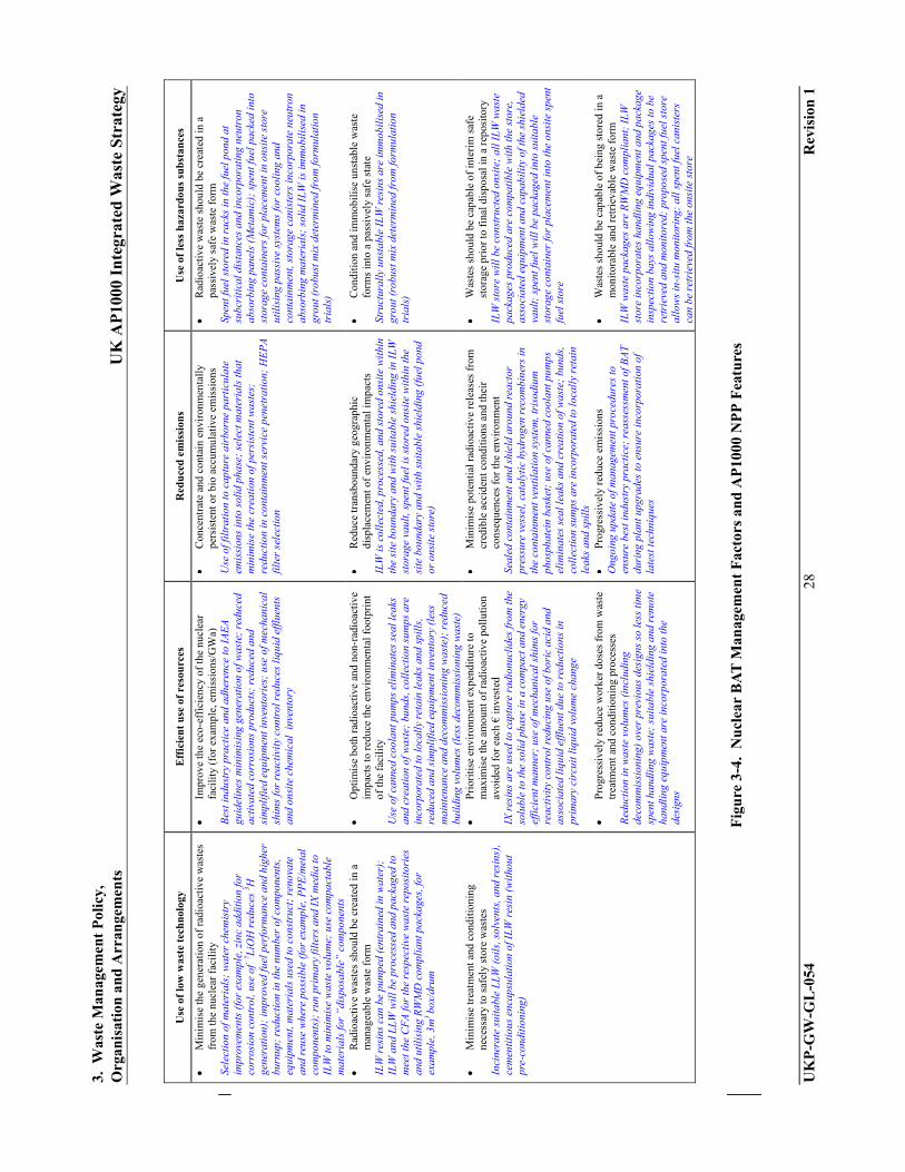
Figure 3-3 and Figure 3-4 (reproduced from [Ref.9]) identify the BAT management factors that are considered to optimise releases. The factors correlate closely with the waste management hierarchy presented in Figure 3-1 and the associated discussion of inherent AP1000 NPP features:
Avoid Use of low waste technology
Minimise Use of low waste technology + Efficient use of resources + Reduce emissions
Reduce/Recycle Use of low waste technology + Use less hazardous substances
Abatement Reduce emissions
Features of the AP1000 NPP generic site design that address the BAT management factors have been added to Figure 3-4.
3.1.2 Orphan Waste
A detailed review of AP1000 NPP systems and rooms was performed to ensure that the creation of waste incompatible with current or developing disposal techniques, commonly called orphan waste, will be as low as reasonably practicable. This review has not identified any orphan waste streams. Estimates of waste generated during operation of the AP1000 NPP and the expected disposal mechanism are presented in Appendix A of [Ref. 4]. A summary of this data, by major reactor system or waste category, is presented in [Ref. 3]. The summaries include conventional and radioactive wastes.

3. Waste Management Policy, Organisation and Arrangements UK AP1000 Integrated Waste Strategy
UKP-GW-GL-054 21 Revision 1
3.1.3 Disposability
Westinghouse has discussed the disposability of AP1000 NPP ILW and spent fuel with the UK NDA, providing information to the NDA to allow a disposability assessment [Ref. 10] to be carried out. The initial conclusion for GDA is that:
“On the basis of the GDA Disposability Assessment for the AP1000, RWMD has concluded that, compared with legacy wastes, no new issues arise that challenge the fundamental disposability of the wastes expected to arise from operation of such a reactor. This conclusion is supported by the similarity of the wastes to those expected to arise from the existing PWR at Sizewell B.”
It is expected that AP1000 NPP operators will transport their ILW and spent fuel offsite as soon as national repositories are available to accept these wastes. Disposal of LLW will follow current practices. This aspect of the IWS can be further developed at the specific site stage.
3.1.4 National Regulatory Environment
This IWS addresses the regulatory framework applicable to an AP1000 NPP deployed on a generic site in England or Wales. When this IWS is further developed to address specific site requirements there may be some variations from the regime as described below to suit the detailed requirements of the specific site. In addition, certain EU legislation is also applicable to the applied regulatory framework.
3.1.5 UK Government Waste Strategy for England 2007
The tenets of the EC Framework Directive on Waste were incorporated in the National Waste Strategy 2000 and as further developed in “The Waste Strategy for England 2007” [Ref. 11] addresses key issues regarding:
The principles of Reduce, Re-use, and Recycle of waste, and energy recovery.
The reduction of waste and diversion from landfill, with reduced cost of regulation.
Targeted action on business sectors with the greatest scope for improving environmental and economic outcomes.
Investment in collection, recycling and recovery.
The improvement of national and local governance, to deliver better coordinated action and services on the ground.
For present purposes, this document makes reference to the waste strategy for England. Similar documents for Scotland [Ref. 12 ] and Wales [Ref. 13 ] exist with similar requirements. The features presented herein will be applicable with suitable adjustments within that country’s legislative framework.
3.1.6 Local and Regional Waste Management Plans
The detailed interfaces between the site waste management plans and the local and regional waste management plans can only be fully developed when the specific site is selected. After the site is selected, consideration could be given to the requirements for interfacing the sites

3. Waste Management Policy, Organisation and Arrangements UK AP1000 Integrated Waste Strategy
UKP-GW-GL-054 22 Revision 1
waste management plans with local and regional waste management plans. When developing the interfaces, aspects requiring consideration will comprise among other things:
EU and national legislative requirements Regional and local policies Consultation processes Identification of waste streams and quantities Identification of waste management options Waste collection and treatment methods Economics of the proposed waste handling methodologies
The detailed interfaces between the site waste management plans and the local and regional waste management plans can only be fully developed when a specific site is selected.
3.1.7 Site Waste Management Plans
Site waste management plans within the construction industry are an example of best practice as a means of reducing and minimizing waste.
Site Waste Management Plans (SWMP) Regulations 2008 (SI 2008 no.314) [Ref. 14] require a site waste management plan to be prepared for any construction project in England with an estimated cost greater than £300,000 excluding VAT.
The Regulations state that “where a nuclear licensed site has an IWS in place that includes waste from construction activities, a separate SWMP is not required, provided all the obligations set out in the SWMP Regulations are included in the strategy.” Construction waste aspects are not addressed herein but can be incorporated into this IWS as described in [Ref. 14]. Upon selection of a specific site, the utility operator will determine whether a separate SWMP will be produced.
3.1.8 Key Legislative Requirements and Regulatory Expectations
All aspects of the site operations will be regulated and the key legislative and regulatory requirements are summarized below. This summary list is not exhaustive and will be reassessed and amended as the IWS is further developed by an AP1000 NPP utility operator.
Legislative Requirements
Significant legislative requirements are addressed within the following:
Controlled Waste Regulations 1992 (and amendments)
Energy Act 2004
Environmental Permitting (England and Wales) Regulations 2007
Environmental Protection Act 1990 (EPA90) (and amendments)
Environmental Protection (Duty of Care) Regulations 1991
Euratom Treaty (Article 37)
Groundwater Regulations 1998

3. Waste Management Policy, Organisation and Arrangements UK AP1000 Integrated Waste Strategy
UKP-GW-GL-054 23 Revision 1
Hazardous Waste Regulations 2005 (and amendments)
Health and Safety at Work etc. Act 1974 (HSWA74)
Ionising Radiations Regulations (IRR99)
Landfill Regulations 2002 (and amendments)
List of Waste Regulations 2005 (and amendments)
Nuclear Industries Security Regulations 2003
Nuclear Installations Act 1965 (NIA 65) (as amended)
Nuclear Reactors (Environmental Impact Assessment for Decommissioning) Regulations 1999 (as amended) (EIADR99)
Pollution Prevention Control (England and Wales) Regulations 2000 (and amendments)
Pollution Prevention and Control (Scotland) Regulations 2000
Radioactive Material (Road Transport) Regulations 2002 (and amendments)
Radioactive Substances Act 1993 (RSA93)
Site Waste Management Plans Regulations (England) 2008
Special Waste Regulations 1996
The Special Waste Amendment (Scotland) Regulations 2004.
Town and Country Planning Act 1990 (TCPA90)
Town and Country Planning (Environmental Impact Assessment) (England and Wales) Regulations 1999 (SI 1999/293)
Transfrontier Shipment of Radioactive Waste Regulations 1993 (and amendments)
Transfrontier Shipment of Waste Regulations 2007 (and amendments)
Waste Electrical and Electronic Equipment Regulations 2006
Waste Management Licensing Regulations 1994 (and amendments)
Water Resources Act 1991 (WRA91)
Regulatory Expectations
Significant regulatory expectations are addressed within the documents listed below:
Management of Radioactive Materials and Radioactive Waste on Nuclear Licensed Sites (HSE, 2001). This document addresses the NII regulatory regime for the management of radioactive materials and wastes on licensed sites.

3. Waste Management Policy, Organisation and Arrangements UK AP1000 Integrated Waste Strategy
UKP-GW-GL-054 24 Revision 1
Nuclear Site License Conditions (HSE, 2009)
Safety Assessment Principles for Nuclear Facilities (SAPs) (HSE, 2006)
Reducing Risks, Protecting People (HSE, 2001)
Decommissioning on Nuclear Licensed Sites (HSE, 2001)
Criterion for Delicensing Nuclear Sites (HSE, 2005)
Environment Agency & Scottish Environmental Protection Agency (SEPA), (2004). PEO guidance.
DETR (2000) Statutory Guidance on the Regulation of Radioactive Discharges into the Environment from Nuclear Licensed Sites.
The Principles of Radioactive Waste Management (IAEA, 1995).
UK Guidance on Radiation Protection Programmes for the Transport of Radioactive Material (Department for Transport, 2002).
Joint HSE, Environment Agency (EA) and SEPA guidance on The Management of Higher Activity Radioactive Waste on Nuclear Licensed Sites.
EA Nuclear Industry Sector Plan
3.1.9 Operator Strategy and Policies
Utility operators will develop and integrate the legislative and regulatory requirements described above when developing site management procedures including those related to waste management.
3.2 Waste Management Organisation
The utility operators of an AP1000 NPP on a specific site will develop this aspect of the IWS and will identify the key roles and responsibilities applicable to waste management. The management structures implemented must ensure that best practice is employed with respect to waste management and that all regulatory requirements are met. Some of the aspects to be considered when defining roles, responsibilities, and procedures within the management structure are:
Ensuring compliance with regulatory requirements
Ensuring proper surveillance, audit and monitoring regimes are in place to maintain accreditations to British, European or international standard; for example, ISO 14001.
Ensuring BPEO, BPM, and BAT requirements are addressed at the time of implementation and are reconsidered for all future amendments to the waste management arrangements.
Ensure that environmental performance of the plant is monitored and recorded. This information can be used to target future investments in waste management.
Stake holder interactions (as further developed in Section 4.7).
3. Waste Management Policy, Organisation and Arrangements UK AP1000 Integrated Waste Strategy
UKP-GW-GL-054 25 Revision 1
3.3 Waste Management Arrangements
As previously stated certain aspects of the IWS will be fully developed for a specific site. One such aspect is the sites Integrated Management System. This should incorporate environmental and safety management features described in [Ref. 1] and will contain details of accreditations to national and internationally recognized standards; for example, BS EN ISO 9001, BS EN ISO 14001. The legislative and regulatory requirements and expectations, associated with environmental and safety management aspects, that will be addressed by the sites Integrated Management Systems are described in subsection 3.1.8.
The sites integrated management system will be developed considering the features of the Waste Management organisation described in Section 3.2 and will address the following:
Control of activities and to prevent and minimise waste arisings
Control of waste management activities which include:
– Waste classification and segregation – Application of the waste hierarchy
Maintenance of arrangements and equipment required to:
– Minimise waste arising – Management of waste – Monitoring and sentencing of waste
Checking the effectiveness of arrangements and equipment required to:
– Minimise waste arising – Management of waste – Monitoring and sentencing of waste
Sharing and use of good practice across waste-streams and projects on the site
Sharing and use of good practice with other sites
Identification of research and technology requirements relating to waste management
Identification of competence and skills requirements relating to waste management
Management of records and information
Management of interfaces with other sites
Much of the detailed information that can be used to inform procedures associated with the waste aspects of the site integrated management system can be found in the detailed designs associated with the AP1000 NPP waste handling systems described in Section 2.2. Detailed information relating to AP1000 NPP systems can be found in the DCD [Ref. 3] and also in the designs associated with the solid radwaste handling systems described in Section 3.4 of the Environment Report [Ref. 4] and the radwaste arisings, management and disposal document [Ref. 15].

3. Waste Management Policy, Organisation and Arrangements UK AP1000 Integrated Waste Strategy
UKP-GW-GL-054 26 Revision 1
Figure 3-1. Waste Management Hierarchy
Figure 3-2. Minimisation of Equipment and Materials
Avoid
Abatement
Recycle/Reuse
Minimise

3. W
aste
Man
agem
ent
Pol
icy,
O
rgan
isat
ion
an
d A
rran
gem
ents
U
K A
P10
00 I
nte
grat
ed W
aste
Str
ateg
y
UK
P-G
W-G
L-0
54
27
Rev
isio
n 1
Fig
ure
3-3
. N
ucl
ear
BA
T M
anag
emen
t F
acto
rs f
or O
pti
mis
atio
n o
f R
elea
ses
from
Nu
clea
r F
acil
itie
s
BA
T
Eff
icie
nt u
se o
f re
sou
rces
R
educ
ed
emis
sion
s
Use
of
low
was
te
tech
nolo
gy
Use
of
less
h
azar
dou
s su
bsta
nce
Rad
ioac
tive
was
tes
shou
ld b
e cr
eate
d in
a p
assi
vely
saf
e w
aste
for
m
Con
diti
on a
nd im
mob
ilis
e un
stab
le w
aste
for
ms
into
a
pass
ivel
y sa
fe s
tate
Was
tes
shou
ld b
e ca
pabl
e of
in
teri
m s
afe
stor
age
prio
r to
fi
nal d
ispo
sal i
n a
repo
sito
ry
Was
tes
shou
ld b
e ca
pabl
e of
be
ing
stor
ed in
a m
onit
orab
le
and
retr
ieva
ble
was
te f
orm
Con
cent
rate
and
con
tain
en
viro
nmen
tall
y pe
rsis
tent
or
bio-
accu
mul
ativ
e em
issi
ons
Red
uce
tran
sbou
ndar
y ge
ogra
phic
dis
plac
emen
t of
envi
ronm
enta
l im
pact
s
Min
imis
e po
tent
ial
radi
oact
ive
rele
ases
fro
m
cred
ible
acc
iden
t con
diti
ons
and
thei
r co
nseq
uenc
es f
or
the
envi
ronm
ent
Pro
gres
sive
ly r
educ
e
Min
imis
e ge
nera
tion
of
radi
oact
ive
was
tes
from
the
nucl
ear
faci
lity
Rad
ioac
tive
was
tes
shou
ld b
e cr
eate
d in
a m
anag
eabl
e fo
rm
Min
imis
e tr
eatm
ent a
nd
cond
itio
ning
nec
essa
ry to
sa
fely
sto
re w
aste
s
Impr
ove
eco-
effi
cien
cy o
f th
e nu
clea
r fa
cili
ty
(e.g
. em
issi
ons/
GW
a)
Opt
imis
e bo
th r
adio
acti
ve
and
non-
radi
oact
ive
impa
cts
to r
educ
e th
e en
viro
nmen
tal
foot
prin
t of
the
faci
lity
Pri
oriti
se e
nvir
onm
enta
l ex
pend
itur
e to
max
imis
e th
e am
ount
of
radi
oact
ive
poll
utio
ns a
void
ed f
or e
ach
euro
inve
sted
Pro
gres
sive
ly r
educ
e w
orke
r do
ses
from
was
te tr
eatm
ent
and
cond
itio
ning
pro
cess
es
3. W
aste
Man
agem
ent
Pol
icy,
O
rgan
isat
ion
an
d A
rran
gem
ents
U
K A
P10
00 I
nte
grat
ed W
aste
Str
ateg
y
UK
P-G
W-G
L-0
54
28
Rev
isio
n 1
Use
of
low
was
te t
ech
nolo
gy
Eff
icie
nt
use
of
reso
urc
es
Red
uce
d e
mis
sion
s U
se o
f le
ss h
azar
dou
s su
bst
ance
s
M
inim
ise
the
gene
rati
on o
f ra
dioa
ctiv
e w
aste
s fr
om th
e nu
clea
r fa
cili
ty
Sele
ctio
n of
mat
eria
ls;
wat
er c
hem
istr
y im
prov
emen
ts (
for
exam
ple,
zin
c ad
ditio
n fo
r co
rros
ion
cont
rol,
use
of 7 L
iOH
red
uces
3 H
gene
ratio
n);
impr
oved
fuel
per
form
ance
and
hig
her
burn
up;
redu
ctio
n in
the
num
ber
of c
ompo
nent
s,
equi
pmen
t, m
ater
ials
use
d to
con
stru
ct;
reno
vate
an
d re
use
whe
re p
ossi
ble
(for
exa
mpl
e, P
PE
/met
al
com
pone
nts)
; ru
n pr
imar
y fi
lter
s an
d IX
med
ia to
IL
W to
min
imis
e w
aste
vol
ume;
use
com
pact
able
m
ater
ials
for
“dis
posa
ble”
com
pone
nts
Im
prov
e th
e ec
o-ef
fici
ency
of
the
nucl
ear
faci
lity
(fo
r ex
ampl
e, e
mis
sion
s/G
Wa)
B
est i
ndus
try
prac
tice
and
adh
eren
ce to
IA
EA
gu
idel
ines
min
imis
ing
gene
ratio
n of
was
te;
redu
ced
acti
vate
d co
rros
ions
pro
duct
s; r
educ
ed a
nd
sim
plif
ied
equi
pmen
t inv
ento
ries
; us
e of
mec
hani
cal
shim
s fo
r re
acti
vity
con
trol
red
uces
liqu
id e
fflu
ents
an
d on
site
che
mic
al i
nven
tory
C
once
ntra
te a
nd c
onta
in e
nvir
onm
enta
lly
pers
iste
nt o
r bi
o ac
cum
ulat
ive
emis
sion
s U
se o
f fil
trat
ion
to c
aptu
re a
irbo
rne
part
icul
ate
emis
sion
s in
to s
olid
pha
se;
sele
ct m
ater
ials
that
m
inim
ise
the
crea
tion
of p
ersi
sten
t was
tes;
re
duct
ion
in c
onta
inm
ent s
ervi
ce p
enet
ratio
n; H
EP
A
filte
r se
lect
ion
R
adio
acti
ve w
aste
sho
uld
be c
reat
ed in
a
pass
ivel
y sa
fe w
aste
for
m
Spen
t fue
l sto
red
in r
acks
in th
e fu
el p
ond
at
subc
riti
cal d
ista
nces
and
inco
rpor
atin
g ne
utro
n ab
sorb
ing
pane
ls (
Met
amic
); s
pent
fuel
pac
ked
into
st
orag
e co
ntai
ners
for
plac
emen
t in
onsi
te s
tore
ut
ilisi
ng p
assi
ve s
yste
ms
for
cool
ing
and
cont
ainm
ent,
stor
age
cani
ster
s in
corp
orat
e ne
utro
n ab
sorb
ing
mat
eria
ls;
solid
ILW
is im
mob
ilis
ed in
gr
out (
robu
st m
ix d
eter
min
ed fr
om fo
rmul
atio
n tr
ials
)
R
adio
acti
ve w
aste
s sh
ould
be
crea
ted
in a
m
anag
eabl
e w
aste
for
m
ILW
res
ins
can
be p
umpe
d (e
ntra
ined
in w
ater
);
ILW
and
LL
W w
ill b
e pr
oces
sed
and
pack
aged
to
mee
t the
CF
A fo
r th
e re
spec
tive
was
te r
epos
itor
ies
and
utili
sing
RW
MD
com
plia
nt p
acka
ges,
for
exam
ple,
3m
3 bo
x/dr
um
O
ptim
ise
both
rad
ioac
tive
and
non
-rad
ioac
tive
im
pact
s to
red
uce
the
envi
ronm
enta
l foo
tpri
nt
of th
e fa
cili
ty
Use
of c
anne
d co
olan
t pum
ps e
lim
inat
es s
eal l
eaks
an
d cr
eati
on o
f was
te;
bund
s, c
olle
ctio
n su
mps
are
in
corp
orat
ed to
loca
lly
reta
in le
aks
and
spil
ls,
redu
ced
and
sim
plifi
ed e
quip
men
t inv
ento
ry (
less
m
aint
enan
ce a
nd d
ecom
mis
sion
ing
was
te);
red
uced
bu
ildi
ng v
olum
es (
less
dec
omm
issi
onin
g w
aste
)
R
educ
e tr
ansb
ound
ary
geog
raph
ic
disp
lace
men
t of
envi
ronm
enta
l im
pact
s IL
W is
col
lect
ed, p
roce
ssed
, and
sto
red
onsi
te w
ithi
n th
e si
te b
ound
ary
and
with
sui
tabl
e sh
ield
ing
in I
LW
st
orag
e va
ult,
spen
t fue
l is
stor
ed o
nsite
with
in th
e si
te b
ound
ary
and
wit
h su
itab
le s
hiel
ding
(fu
el p
ond
or o
nsit
e st
ore)
C
ondi
tion
and
imm
obil
ise
unst
able
was
te
form
s in
to a
pas
sive
ly s
afe
stat
e St
ruct
ural
ly u
nsta
ble
ILW
res
ins
are
imm
obil
ised
in
grou
t (ro
bust
mix
det
erm
ined
from
form
ulat
ion
tria
ls)
M
inim
ise
trea
tmen
t and
con
diti
onin
g ne
cess
ary
to s
afel
y st
ore
was
tes
Inci
nera
te s
uita
ble
LL
W (
oils
, sol
vent
s, a
nd r
esin
s),
cem
enti
tiou
s en
caps
ulat
ion
of I
LW r
esin
(w
itho
ut
pre-
cond
itio
ning
)
P
rior
itis
e en
viro
nmen
t exp
endi
ture
to
max
imis
e th
e am
ount
of
radi
oact
ive
pollu
tion
avoi
ded
for
each
€ in
vest
ed
IX r
esin
s ar
e us
ed to
cap
ture
rad
ionu
clid
es fr
om th
e so
lubl
e to
the
solid
pha
se in
a c
ompa
ct a
nd e
nerg
y ef
fici
ent m
anne
r; u
se o
f mec
hani
cal s
him
s fo
r re
acti
vity
con
trol
red
ucin
g us
e of
bor
ic a
cid
and
asso
ciat
ed li
quid
effl
uent
due
to r
educ
tion
s in
pr
imar
y ci
rcui
t liq
uid
volu
me
chan
ge
M
inim
ise
pote
ntia
l rad
ioac
tive
rele
ases
fro
m
cred
ible
acc
iden
t con
ditio
ns a
nd th
eir
cons
eque
nces
for
the
envi
ronm
ent
Seal
ed c
onta
inm
ent a
nd s
hiel
d ar
ound
rea
ctor
pr
essu
re v
esse
l, ca
taly
tic
hydr
ogen
rec
ombi
ners
in
the
cont
ainm
ent v
enti
lati
on s
yste
m, t
riso
dium
ph
osph
atei
n ba
sket
; us
e of
can
ned
cool
ant p
umps
el
imin
ates
sea
l lea
ks a
nd c
reat
ion
of w
aste
; bu
nds,
co
llec
tion
sum
ps a
re in
corp
orat
ed to
loca
lly
reta
in
leak
s an
d sp
ills
W
aste
s sh
ould
be
capa
ble
of in
teri
m s
afe
stor
age
prio
r to
fin
al d
ispo
sal i
n a
repo
sito
ry
ILW
sto
re w
ill b
e co
nstr
ucte
d on
site
; al
l IL
W w
aste
pa
ckag
es p
rodu
ced
are
com
pati
ble
wit
h th
e st
ore,
as
soci
ated
equ
ipm
ent a
nd c
apab
ility
of t
he s
hiel
ded
vaul
t; s
pent
fuel
wil
l be
pack
aged
into
sui
tabl
e st
orag
e co
ntai
ner
for
plac
emen
t int
o th
e on
site
spe
nt
fuel
sto
re
Pro
gres
sive
ly r
educ
e w
orke
r do
ses
from
was
te
trea
tmen
t and
con
ditio
ning
pro
cess
es
Red
ucti
on in
was
te v
olum
es (
incl
udin
g de
com
mis
sion
ing)
ove
r pr
evio
us d
esig
ns s
o le
ss ti
me
spen
t han
dlin
g w
aste
; su
itabl
e sh
ield
ing
and
rem
ote
hand
ling
equi
pmen
t are
inco
rpor
ated
into
the
desi
gns
Pr
ogre
ssiv
ely
redu
ce e
mis
sion
s O
ngoi
ng u
pdat
e of
man
agem
ent p
roce
dure
s to
en
sure
bes
t ind
ustr
y pr
acti
ce;
reas
sess
men
t of B
AT
du
ring
pla
nt u
pgra
des
to e
nsur
e in
corp
orat
ion
of
late
st te
chni
ques
W
aste
s sh
ould
be
capa
ble
of b
eing
sto
red
in a
m
onit
orab
le a
nd r
etri
evab
le w
aste
for
m
ILW
was
te p
acka
ges
are
RW
MD
com
plia
nt;
ILW
st
ore
inco
rpor
ates
han
dlin
g eq
uipm
ent a
nd p
acka
ge
insp
ecti
on b
ays
allo
win
g in
divi
dual
pac
kage
s to
be
retr
ieve
d an
d m
onit
ored
; pr
opos
ed s
pent
fuel
sto
re
allo
ws
in-s
itu m
onito
ring
; al
l spe
nt fu
el c
anis
ters
ca
n be
ret
riev
ed fr
om th
e on
site
sto
re
Fig
ure
3-4
. N
ucl
ear
BA
T M
anag
emen
t F
acto
rs a
nd
AP
1000
NP
P F
eatu
res
4. Formulation of Integrated Waste Management Strategy UK AP1000 Integrated Waste Strategy
UKP-GW-GL-054 29 Revision 1
4. FORMULATION OF INTEGRATED WASTE MANAGEMENT STRATEGY
4.1 Overview
A strategy for the management of radioactive wastes, fuel, and conventional waste has been developed for the GDA. During site-specific analysis, the utility operator of an AP1000 NPP may develop his own strategy that would change or replace the strategy discussed herein. The utilities, the eventual AP1000 NPP operators, were involved in the design evolution of the solid radwaste management facilities, a significant proportion of which was their participation in the Best Available Techniques (BAT) Assessment Workshop, and a closeout review of the designs. Also, the utilities participated in weekly teleconferences in which a collaborative approach was adopted, and learning from experience (LFE) was a prevalent ongoing feature of the design process. Joint environmental and safety assessments were used to achieve an overall balance between environmental and safety matters.
4.2 Methodology for Strategic Options Study
[Ref. 1] states: “An Integrated Waste Strategy can be considered to be optimized when it is the outcome of a systematic and consultative decision making process that has considered a range of options (including those involving cooperation with other sites or organizations) and their practicability.”
This has been carried out for the AP1000 NPP in the manner described in Section 4.1 above. AP1000 NPP operators may further develop these option studies to address site-specific waste management issues and to further support the AP1000 NPP design.
4.3 Site Prioritisation Logic
4.3.1 Waste Hierarchy
It is expected that the principles of the Waste Hierarchy, Figure 3-1, will be applied to justify the waste processes and practices adopted for the AP1000 NPP and these have been described in Section 3.1 for the AP1000 NPP design. Operators of the AP1000 NPP will develop waste management procedures that address the intent of the waste management hierarchy and take account of site-specific requirements.
4.3.2 Safety and Environmental Detriment
When developing the IWS further, AP1000 NPP operators may also use the NDA prioritization process [Ref. 16] when considering waste management options. This process involves the calculation of the Safety and Environmental Detriment for wastes using a multi-attribute decision analysis (MADA) model. If appropriate, this might be carried out using site-specific data at a later stage in the GDA process.
4.4 Waste Management Constraints and Dependencies
At this stage in the GDA process, it has been assumed that there are no waste management constraints although some of the assumptions and exclusions considered are listed in Table 4-1.
Following further assessment by the utility operator, these could be considered under three headings:
Regulatory Financial Programme

4. Formulation of Integrated Waste Management Strategy UK AP1000 Integrated Waste Strategy
UKP-GW-GL-054 30 Revision 1
4.5 Site End Points and Contaminated Land
Whilst this part of the strategy has not been detailed at this stage, it is expected that the intended Site End Point and the subsequent management of contaminated land if appropriate will be addressed here by the utility operator as part of the IWS.
The site End State is discussed below. It is noted that the eventual End State may be subject to national consultation and rationalization with future UK Government policy.
The current End State is described below:
Structures if present will be deplanted and demolished during Final Site Clearance (FSC).
Buildings will be removed down to a depth of 1 m below ground level.
Roads, car parks, underground services, and the like, will be removed.
The active drains and outfall will be removed. Foul and surface water drains will be removed if less than 1 m below ground level.
Basements if present will be demolished to 1m below ground level and any remaining subsurface structures punctured to assist drainage.
Land requiring remediation will be identified and treated appropriately.
Ground will be appropriately landscaped, and land drains installed if required.
After FSC, the site will be released from its Nuclear Site License typically for use as a brownfield site.
4.6 Assumptions, Exclusions, Risks, and Opportunities
A comprehensive set of assumptions, exclusions, risks, and opportunities will be developed for each specific site, operator, and licensing conditions and constraints. The waste management proposals for the GDA are based on certain key assumptions and exclusions as listed in Table 4-1.
4.7 Stakeholder Engagement
Plant operators will develop specific stakeholder IWS engagement processes. The engagement process will be designed to ensure a wide ranging and inclusive consultation on relevant issues. The process shall be flexible to allow engagement on any topics determined by the plant operator and should also allow alignment with other stake holder processes. The stake holder engagement process developed for the specific site must incorporate:
Independence Transparency Openness Clarity Accessibility

4. Formulation of Integrated Waste Management Strategy UK AP1000 Integrated Waste Strategy
UKP-GW-GL-054 31 Revision 1
During development, the stake holder engagement process should consider diverse mechanisms to ensure that information is adequately communicated and stake holders have adequate opportunity for engagement; for example:
Engagement workshops Plant operator website Posting information in local public buildings Site visitor centre
Because the IWS will be a living document that will be developed throughout the life of an operating AP1000 NPP plant, stake holder involvement will be sought at all pertinent opportunities.
Typical stakeholders could comprise:
Local Authorities and Bodies; for example, town and parish councils, and district and county councils
Local Organisations; for example, landowners associations, national farmer union, business associations, local members of parliament, and local residents
Emergency and Health Services; for example, Civil Nuclear and County Constabularies, and county fire and rescue services
Government Agencies and Regulators; for example, Environment Agency, Food Standards Agency, Nuclear Installations Inspectorate, Nuclear Decommissioning Agency, Office for Civil Nuclear Security.
AP1000 NPP operators
Many of the features of a stake holder engagement process and associated communication mechanisms are detailed in [Ref. 2].

4. Formulation of Integrated Waste Management Strategy UK AP1000 Integrated Waste Strategy
UKP-GW-GL-054 32 Revision 1
Table 4-1
ASSUMPTIONS AND EXCLUSIONS
Item Description
Assumption 1 National Low Level Waste Repository is available within 2 years of site operations commencing
Assumption 2 National Intermediate level waste repository will be available before the end of the onsite ILW store building design period (before the end of this century)
Assumption 3 National High Level Waste (Spent Fuel) repository will be available before the end of the design period of the onsite spent fuel store (before the end of this century)
Assumption 4 No major changes in legislation during the operational period of the AP1000 NPP and the associated onsite waste facilities.
Assumption 5 Planning permissions for the spent fuel store and the extensions to the ILW store will be granted.
Assumption 6 No major restrictive changes to discharge limits during the operational period of the AP1000 NPP
Exclusion 1 External hazards and events that could cause major disruptions other than those already assumed in the safety case
Exclusion 2 Post Closure Monitoring, requirements are not specified here.
Exclusion 3 Post Closure Management, requirements are not specified here.
Exclusion 4 Variations in Discharge

5. Overview of Site Waste Strategy UK AP1000 Integrated Waste Strategy
UKP-GW-GL-054 33 Revision 1
5. OVERVIEW OF SITE WASTE STRATEGY
5.1 Overview
The waste expected to be generated during the operation period of an AP1000 NPP is summarised in Chapter 3 of [Ref. 4].
Radioactive low and intermediate level solid wastes will be processed and stored onsite (see Section 6 for details). Storage for LLW is limited to 2 years arisings and provides buffer storage between an AP1000 NPP and the national LLW repository. At present, a national repository for ILW is not available and processed solid ILW will be stored onsite within a shielded store.
Spent Fuel is stored initially within the fuel pond and later within an onsite store, awaiting shipment to a future national HLW repository.
Conventional wastes are collected by AP1000 NPP systems, processed if applicable, and discharged to the environment. Certain wastes are collected (for example, waste oil) and sent offsite for disposal at specialist facilities. Wherever possible, certain wastes will be recycled.
Detailed information relating to all AP1000 NPP waste streams and disposal routes is presented in [Ref. Error! Bookmark not defined.] Chapter 3 of [Ref. 4].
5.2 Milestones
There are a number of key milestones applicable to the waste strategy; for example, construction of the AP1000 NPP, construction of waste processing and storage facilities, and generation of first wastes. These and other milestones, with example dates, are shown in Figure 2-3 and Figure 5-1. A detailed disposability plan for ILW and HLW can be found in [Ref. 17].

5. O
verv
iew
of
Sit
e W
aste
Str
ateg
y U
K A
P10
00 I
nte
grat
ed W
aste
Str
ateg
y
UK
P-G
W-G
L-0
54
34
Rev
isio
n 1
Fig
ure
5-1
. M
iles
ton
es A
pp
lica
ble
to
Was
te S
trat
egy

6. Integrated Waste Management Strategy UK AP1000 Integrated Waste Strategy
UKP-GW-GL-054 35 Revision 1
6. INTEGRATED WASTE MANAGEMENT STRATEGY
6.1 Overview
As previously described, AP1000 NPP design and suggestions for management arrangements incorporate features of the waste management hierarchy, realising the intent to avoid the generation of waste, minimise the generation of waste, reuse or recycle waste wherever possible, and implement abatement schemes to reduce controlled releases to the environment ALARP. This is discussed in Section 3.1. Waste streams have been identified and associated strategies are described below (also see Figures 6-1 through 6-9). In certain cases, these strategies are closely related to the current phase of the GDA and at a specific site or at some future time due to regulatory changes or technological development, there may be a modification of the strategies described. Future developments and modifications of the IWS will be undertaken by AP1000 NPP operators.
6.2 Radioactive Waste Management Cases
It is expected that RWMCs will be produced for the radioactive waste streams identified below. The RWMC will address the requirements identified in [Ref. 18]. RWMC evidence reports identifying the source of key information required to prepare the RWMC have been prepared [Ref. 5] and [Ref. 6].
6.3 Conventional Solid Waste Strategy
The expected volumes of conventional waste generated will benefit from good management arrangements coupled to the features inherent in the AP1000 NPP design. These features, when combined with best industry practice operating regimes lead to a reduction in the volumes of conventional waste generated. The strategy for this waste stream is to dispose of the waste in licensed facilities. Conventional waste arisings are collected and sorted onsite prior to shipment to recycling or waste disposal facilities. In other cases, the waste will be disposed of in a manner that has the least environmental impact.
6.4 Conventional Gaseous Strategy
The strategy for dealing with conventional gaseous effluent releases from an AP1000 NPP is to discharge directly to the environment. Sources of potential gaseous release are described below with justification of the approach taken.
6.4.1 Emissions Sources
6.4.1.1 Mobile Encapsulation Plant
The mobile encapsulation plant stabilises ILW by mixing with cementitious grout. The use of premixed grout is preferred however, in the absence of a suitable source of premixed grout, it will be necessary to mix the cementitious grout onsite from bagged dry, powdered materials. If powdered grout materials are handled onsite, then local extraction systems and bag filters will be provided to reduce dust emissions.
6.4.1.2 Standby Generators
There are four diesel generators on the AP1000 NPP:
Two onsite standby diesel generators, output rated at 4000 kW Two ancillary diesel generators, output rated at 80 kW

6. Integrated Waste Management Strategy UK AP1000 Integrated Waste Strategy
UKP-GW-GL-054 36 Revision 1
During operation the diesel generators will emit combustion gases including sulfur dioxide, nitrogen dioxide, carbon monoxide and particulates. However, these generators will only operate for a few hours per year during mains power failure or during testing. The annual emissions of combustion gases from the generators will be negligible and no exhaust gas treatment systems are required.
The ancillary generators are rated at less than one percent of the power of the standby generators. The contribution of these generators to the overall air pollution is minimal and here again no exhaust gas treatment is required.
6.5 Conventional Liquid Strategy
The strategy for handling conventional liquid wastes arising from operations is to treat, whenever possible, using AP1000 NPP systems and discharge treated effluent to the environment. The treatment systems utilised prevent the uncontrolled release of contaminants to the environment, make use of currently understood BAT, and ensure that all allowed discharges are as low a reasonably practicable. A brief description of treatment facilities and associated influents and effluents is given below. Further information may be found in [Ref. 3] and [Ref. 4]. There may be circumstances that require the use of mobile treatment facilities or the collection of effluents for treatment at licensed off-site facilities. These cases are identified below.
6.5.1 Treatment and Disposal of Non-Radioactive Effluent – Waste Water System
The non-radioactive waste water during normal plant operation and during plant outages is handled by the waste water system (WWS). Wastes from the turbine building floor and equipment drains (which include laboratory and sampling sink drains, oil storage room drains, main steam isolation valve compartment, auxiliary building penetration area, and auxiliary building HVAC room) are collected in the two turbine building sumps. Drainage from the diesel generator building sumps, the auxiliary building sump north (a non-radioactive sump), and the annex building sump is also collected in the turbine building sumps. The turbine building sumps provide a temporary storage capacity and a controlled source of fluid flow to the oil separator.
A radiation monitor located on the common discharge piping of the sump pumps provides an alarm upon detection of radioactivity in the waste water. In the event radioactivity is present in the turbine building sumps, the waste water is diverted from the sumps to the WLS for processing and disposal. The radiation monitor also trips the sump pumps on detection of radioactivity to isolate the contaminated waste water. Provisions are included for sampling the sumps.
The turbine building sump pumps route the waste water from either of the two sumps to the oil separator for removal of oily waste. The diesel fuel oil area sump pump also discharges waste water to the oil separator. The oil separator has internal, vertical coalescing tubes for removal of oily waste which flows by gravity to the waste oil storage tank. The waste oil storage tank provides temporary storage prior to removal by truck for offsite disposal. A bypass line allows for the oil separator to be out of service for maintenance. The bypass line will be normally closed.
The waste water from the oil separator flows by gravity to the waste water retention basin (WWRB) for settling of suspended solids and treatment, if required, prior to discharge. The detailed design and configuration of the plant waste water retention basins and associated discharge piping, including piping design pressure, basin transfer pump size, basin size, and location of the retention basins will be made according to site-specific conditions.

6. Integrated Waste Management Strategy UK AP1000 Integrated Waste Strategy
UKP-GW-GL-054 37 Revision 1
Wastewater that complies with discharge limits will be released intermittently via the seawater cooling return sump for final discharge via the plant outfall to the sea.
6.5.2 Systems Discharging to the Waste Water System
6.5.2.1 Demineralised Water Treatment System
The demineralised water treatment system (DTS) receives water from the raw water system, processes this water to remove ionic impurities, and provides demineralised water to the demineralised water transfer and storage system. The treatment system comprises cartridge filters, two reverse osmosis units, and electrodeionisation systems. The reject flow or brine from the first reverse osmosis unit is discharged to the WWS. A pH adjustment chemical is added from the turbine island chemical feed system to maintain the system within the operating range of the reverse osmosis membranes to inhibit scaling and corrosion. A dilute anti-scalant, which is chemically compatible with the pH adjustment chemical feed, is metered into the reverse osmosis influent water to increase the solubility of salts (decrease formation on the membranes).
6.5.2.2 Steam Generator Blowdown System
The steam generator blowdown system (BDS) assists in maintaining acceptable secondary coolant water chemistry during normal operation and during anticipated operational occurrences of main condenser in-leakage or primary to secondary steam generator tube leakage by removing impurities which are concentrated in the steam generator. The BDS consists of two blowdown trains, one for each steam generator. The steam generator blowdown system accepts water from each steam generator and processes the water as required. If significant radioactivity is detected in secondary side systems, blowdown is re-directed to the WLS. However, normal operation is for the blowdown from each steam generator to be processed by a regenerative heat exchanger to provide cooling and an electrodeionisation demineralising unit to remove impurities from the blowdown flow. The blowdown fluid is then normally recovered for reuse in the condensate system. Blowdown with high levels of impurities can be discharged directly to the WWS. A small waste stream from the electrodeionisation system may also be directed to the WWS or the WLS.
6.5.2.3 Condensate System
The condensate system (CDS) provides feedwater at the required temperature, pressure, and flow rate to the deaerator. Condensate is pumped from the main condenser hotwell by the condensate pumps and passes through the low-pressure feedwater heaters to the deaerator. During startup, the condensate is treated by ion exchange resin in the condensate polishing system (CPS) to ensure the condensate and feedwater system water chemistry meets specifications. Upon removal of the exhausted resin from the polisher vessel, the vessel is rinsed and the new resin is placed in the vessel using the resin addition hopper and eductor. Prior to plant startup, a new resin bed is rinsed and resin performance is verified, with flow through the vessel discharged to the WWS.
6.5.3 Sanitary Drainage System
The sanitary drainage system (SDS) is designed to collect the site sanitary waste (from plant restrooms and locker room facilities in the turbine building, auxiliary building, and annex building) for treatment, dilution, and discharge. The sanitary drainage system does not service facilities in radiologically controlled areas. The sanitary drainage system transports sanitary waste to either an onsite or an offsite waste treatment plant. The selection of the waste treatment plant option is site specific and is outside the scope of the generic site AP1000 NPP application.

6. Integrated Waste Management Strategy UK AP1000 Integrated Waste Strategy
UKP-GW-GL-054 38 Revision 1
6.5.4 Seawater Cooling Systems
The two seawater cooling systems are described below.
6.5.4.1 Circulating Water System
The circulating water system (CWS) supplies cooling water to remove heat from the main condensers, the turbine building closed cooling water system heat exchangers, and the condenser vacuum pump seal water heat exchangers. The cooling water system is a site-specific design, and for the GDA generic coastal site, a once-through seawater cooling system is used with warm reject seawater being discharged directly to the sea via the cooling water return. A once-through seawater cooling system will be dosed with sodium hypochlorite to control biofouling when seawater temperatures exceed 10C.
6.5.4.2 Service Water System
The service water system (SWS) supplies cooling water to remove heat from the nonsafety-related component cooling water system heat exchangers in the turbine building. Like the CWS, for the GDA a once-through seawater cooling system will be used for a generic coastal site. The SWS uses ~4% of the seawater cooling flow of the CWS. This will be dosed with sodium hypochlorite to control biofouling when seawater temperatures exceed 10C.
The option for the use of cooling towers for the SWS has been retained for consideration at specific sites. Further information on this can be found in Section 7 of the Environment report [Ref. 4]
6.5.5 Closed Loop Cooling Systems
Closed loop cooling systems do not normally result in discharges to the waste water system. Discharges arise only in the event of maintenance or as a result of blowdown to maintain water chemistry or leakage. The closed loop cooling systems are described below.
6.5.5.1 Component Cooling Water System
The component cooling water system (CCS) is a nonsafety-related, closed loop cooling system that transfers heat from various plant components to the service water system during normal phases of operation. Cooling medium is provided by the service water system. The component cooling water system also provides a barrier against leakage of service water into primary containment and reactor systems. Leakage of reactor coolant into the component cooling water system is detected by a radiation monitor on the common pump suction header, by routine sampling, or by high level in the surge tank.
6.5.5.2 Central Chilled Water System
The central chilled water system (VWS) supplies chilled water to the HVAC systems and is functional during reactor full-power and shutdown operation. It also supplies chilled water to the WLS, WGS, secondary sampling system, and the temporary air supply units of the containment leak rate test system. The chemical feed tanks and associated piping are used to add chemicals to each chilled water subsystem stream to maintain proper water quality. Antifreeze solution is added to the low capacity subsystem to prevent freezing during cold weather operation.

6. Integrated Waste Management Strategy UK AP1000 Integrated Waste Strategy
UKP-GW-GL-054 39 Revision 1
6.5.5.3 Turbine Building Closed Cooling System
The turbine building closed cooling system (TCS) is a closed loop system which provides chemically treated, demineralised cooling water for the removal of heat from non-safety-related heat exchangers in the turbine building and rejects the heat to the circulating water system. The cooling water is treated with a corrosion inhibitor, and it uses demineralised water for makeup.
6.5.6 Chemicals Discharged with Liquid Effluents
The chemical use in the AP1000 NPP has been identified in [Ref. 4]. Some of these chemicals are released with liquid effluent discharges into the seawater cooling return.
As a point of reference, the normal flow rate of once through seawater cooling is approximately two thousand times the normal flow rate of the non-radioactive effluent discharges [Ref. 4]
The concentrations of chemicals present in the effluent discharges are estimated in [Ref. 4].
6.5.6.1 Sodium Hypochlorite and Halogenated By-Products
The use of biocides is essential to prevent biofouling cooling water systems. Sodium hypochlorite, is used as a biocide in the AP1000 NPP cooling water systems. The level of sodium hypochlorite dosing will be minimised by using BAT design of the cooling water system to minimize the potential for biofouling. Good design of the dosing and monitoring systems will reduce the level of hypochlorite dosing required still further. These two factors will minimise the discharge of both residual oxidant and chlorination byproducts to the receiving waters.
The chlorination of seawater can give rise to the formation of halogenated by-products. A mixture of chlorinated and brominated compounds is formed due to the reaction of the chlorine with bromide. Brominated species normally predominate and, whilst generally more toxic, they tend to breakdown more rapidly in the environment. Trihalomethanes and halogenated acetic acids are the most common by-products formed. The quantities of by-products formed will be site specific. Factors affecting the by-product formation include the applied chlorine dose, the concentration of organic carbon in the water, temperature, pH and contact time. The concentrations of halogenated by-products can be minimized by the use of good design of the dosing and monitoring systems to minimize the sodium hypochlorite dose rates and residual chlorine discharges. A summary of common by-products of chlorination in seawater is listed in [Ref. 4].
6.5.6.2 Boric Acid
The AP1000 NPP discharges borated reactor coolant water in the radioactive liquid waste discharges. The boron is not removed by the ion exchange beds in the WLS because these operate in a boron saturated mode. The quantity and concentration of boric acid discharged and its relationship to the environmental quality standard is identified in [Ref. 4]. When compared to an annual average environmental quality standard for seawater, the boron discharge can be considered negligible.
6.5.6.3 Trace Metals
Zinc acetate is dosed into the reactor coolant system to reduce corrosion and when reactor coolant water is letdown via the CVS a small amount of zinc acetate will be released. The

6. Integrated Waste Management Strategy UK AP1000 Integrated Waste Strategy
UKP-GW-GL-054 40 Revision 1
zinc will be removed by passage through the WLS ion exchange resins and so no release of zinc is expected in the AP1000 NPP liquid discharges from this source.
Some trace metal impurities may be present in the bulk chemical dosed into the various AP1000 NPP water systems. The basis for the assessment of trace metal releases and its relationship to applicable environmental quality standards is presented in [Ref. 4]. When compared to the applicable environmental quality standards, the worst case metal concentration predicted in the AP1000 NPP effluent discharge can be considered to be negligible.
The non-radioactive metal discharges associated with corrosion products have not been predicted for the AP1000 NPP. However, the presence of iron, nickel, copper, and chromium might all be expected in trace quantities.
6.5.6.4 Other Chemicals
Other chemical discharges and associated concentrations are identified in [Ref. 4] and include ammonium hydroxide, ammonium chloride, polyacrylate, and lithium-7 hydroxide. There are no relevant environmental quality standards to compare these discharge concentrations against.
6.5.6.5 Containment of Unplanned Emissions
The AP1000 NPP site-specific design will have sufficient containment within the WWRB to retain unplanned emissions of effluents, spillages. The quality of these discharges can be ascertained by sampling and analysis from the WWRB to determine whether direct discharge is acceptable. If the water quality is unacceptable, then a mobile treatment system can be brought in to deal with the effluent or vacuum tankers can be used to remove the off-specification effluent to a licensed treatment plant.
6.5.7 Stormwater
Storm water falling on outdoor areas of hardstanding will drain to a storm water pond or sustainable urban drainage system (SUDS) to minimise the risk of contamination or flooding of receiving waters. An oil water separator will be incorporated to prevent oily spillages on roads and loading bays from being carried over to discharge. The details of the storm water management will developed in the site-specific design.
6.5.8 Firewater
Fire water from internal fire fighting systems will be retained within the lower levels of the buildings. Fire water used externally will fall on hardstanding areas and be collected in the storm water pond or SUDS system. If the water quality is unacceptable then a mobile treatment system can be brought in to deal with the effluent or vacuum tankers can be used to remove the off-specification effluent to a licensed treatment plant.
6.6 Low Level Solid Radioactive Waste Strategy
At a strategic level, it is intended that LLW will be collected within the AP1000 NPP and transferred to the radwaste building. Waste will then be sorted and categorised. Wherever possible, waste items will be decontaminated to the extent that allows recycling or free release (via the clearance and exemption area) and handling as conventional waste. LLW will be shipped offsite for disposal at licensed facilities.

6. Integrated Waste Management Strategy UK AP1000 Integrated Waste Strategy
UKP-GW-GL-054 41 Revision 1
Within the AP1000 NPP, the volumes of LLW waste generated by operation, maintenance, and decommissioning of an AP1000 NPP benefit from the features inherent in the design particularly relating to reductions in the number of items of equipment, components, and materials. These features, combined with best industry practice operating regimes (for example, by limiting the amount of material brought into containment), lead to a reduction in the volumes of LLW waste generated.
Compactable items will be sorted and compacted in drum to reduce packed volumes. Non compactable items will be cut into pieces to allow packing into drums. Full drums will be assayed with an LRGS and placed into HHISO containers and when full, HHISO containers can be stored onsite in the LLW buffer store prior to shipment to the national LLW repository.
Under normal circumstance, CPS resins are not radioactive and will be sent to licensed incineration facilities for disposal. However, under abnormal conditions – for example, steam generator tube failures – there may be a transfer of primary circuit activity into the secondary circuit. The amount of activity transferred will be very small and the activity of the CPS resin will not exceed the limits for LLW. Incineration will remain the disposal route so long as the activity of the CPS resin is within the CfA for the incineration facility. There may be situations when the activity of the CPS resin exceeds the CfA for incineration (although still LLW) and in these cases, the resin will be encapsulated into a compliant container (for example, 220l drum) using mobile plant and equipment operated by specialist subcontractors. The encapsulated packages are then placed into HHISO containers and are ultimately disposed of at the national LLW repository.
The disposal route for CPS resin is shown pictorially in Figure 6-2.
6.6.1 Radioactive Gaseous Waste Strategy
The gaseous radwaste is produced as a result of normal operations within an AP1000 NPP as described in subsection 2.2.2.
The strategy relating to radioactive gaseous discharges is to treat to the extent practicable using AP1000 NPP systems, to monitor and release to the environment.
The gaseous radwaste stream enters a once-through, ambient temperature, activated carbon delay system (Figure 6-4). When the WGS is in use, its operation is passive, using the pressure provided by the influent sources to drive the waste gas through the system.
The expected impact of gaseous discharges have been assessed for humans within the AP1000 NPP generic individual and collective dose assessments Section 5.2 of [Ref. 4] and for non-human species in Section 5.3 [Ref. 4]. These have all been found to be acceptably low.
6.6.2 Radioactive Liquid Strategy
The strategy related to radioactive liquids is to treat to reduce activity using BAT to the extent practicable and to discharge to the environment following a suitable monitoring period. The mechanisms for dealing with radioactive liquids including waste oils are described below.

6. Integrated Waste Management Strategy UK AP1000 Integrated Waste Strategy
UKP-GW-GL-054 42 Revision 1
6.6.2.1 Treated Liquid Effluents
Liquid effluents are processed by AP1000 NPP systems primarily ion-exchange to eliminate radionuclides in the effluent. Once processed, the resulting effluents are expected to contain very low levels of radioactivity and are collected in liquid waste hold up (monitoring) tanks. Following a period of monitoring, the liquid waste is discharged to the environment. Out of specification liquids will be recycled back through AP1000 NPP systems for additional processing.
6.6.3 Waste Oils
Waste oils are collected, and if necessary, water is separated. If the waste oil is non-radioactive or LLW and it meets the conditions for acceptance for incineration, it will be sent to external facilities for incineration. Suitable incineration facilities exist in the United Kingdom and in Europe. Should the waste oil not meet the conditions for acceptance for incineration, it can be solidified using proprietary polymeric chemicals (for example, nochar) and disposed as solid LLW or the waste can be incinerated in other European incineration facilities, the dry residue being returned for encapsulation. The waste oil route is shown pictorially in Figure 6-6.
6.7 Intermediate Level Waste Strategy
AP1000 NPP design and systems minimise the production of ILW operational waste. For example, the fuel used provides excellent performance with very low defect rates when combined with excellent water chemistry control. As identified in [Ref. 7], the careful selection of materials used in the construction of an AP1000 NPP and the minimisation of the number of equipment items, components, materials (pipework, cabling, and the like) contribute significantly to a reduction in maintenance and decommissioning ILW wastes.
The strategy for dealing with ILW waste arisings is to process the waste into a stable form using mobile facilities and then to store onsite in the ILW store. The ILW processing and storage facilities are discussed in subsection 2.2.3.
Following development of the ILW repository, waste packages will be shipped from the onsite ILW store for final disposal. The waste inventory is generated approximately constantly over the lifetime of the plant.
There are also intermediate level waste streams that will arise as a result of decommissioning an AP1000 NPP. The strategy for dealing with these waste streams is summarised in Section 6.9 (below) and also in [Ref. 8] and Chapter 20 of the DCD [Ref 3].
6.8 Spent Fuel Strategy
Spent fuel (HLW) is generated during normal reactor operations and is initially stored within the spent fuel pond. This fuel pond has sufficient capacity for up to 18 years storage, including a full core discharge. Spent fuel will not be reprocessed, and fuel assemblies, loaded into suitable casks, will be sent to the national HLW repository. If the repository is not available within a suitable time scale, then the spent fuel can be retained onsite until the end of this century within the dry spent fuel store.
6.9 Decommissioning Waste
During decommissioning, the buildings, structure, and equipment of the AP1000 NPP are removed in order to return the site to such a state that it can be released for redevelopment or

6. Integrated Waste Management Strategy UK AP1000 Integrated Waste Strategy
UKP-GW-GL-054 43 Revision 1
return to agriculture. Radioactive and conventional wastes will be removed to the extent required to allow de-licensing.
The International Atomic Energy Agency (IAEA) has identified three decommissioning strategies [Ref. 19], and these are:
Immediate dismantling. Deferred dismantling. Entombment.
The preferred IAEA strategy is for immediate dismantling and the AP1000 NPP is designed to allow the site to be completely cleared with all wastes generated being handled as conventional, LLW, ILW, or spent fuel.
Detailed information is available in [Ref. 8] and Chapters 20 of the DCD [Ref. 3]; however, for clarity, a brief summary of decommissioning and associated waste handling is presented below.
This aspect of the IWS can be considered further through the operational period of an AP1000 NPP and developed alongside decommissioning plans as the end of the operational period approaches. This allows for consideration of improved waste management techniques and technologies to be catered for. It also allows for the potential availability of national waste repositories to be taken into account.
6.9.1 AP1000 NPP Decommissioning Design Features
Within the design of the AP1000 NPP, there are many features, as discussed in Section 3 above, that facilitate the eventual decommissioning of the plant versus previous designs; for example:
Reduced equipment numbers giving a reduction in the amount of waste requiring management
Careful materials selection giving reductions in activation of equipment and structure
Reduction in activated corrosion products by improved control of primary circuit water chemistry (pH range; 6.9-7.4) and suitable dosing regimes; for example, zinc acetate
Many of the design features present in the AP1000 NPP give reduction in the amount of radioactive waste generated and the activity present in radioactive waste streams.
6.9.1.1 Sources of Radioactivity
The principle sources of radioactivity in the plant after final shutdown and de-fuelling are classified as follows:
Fixed activated structures Contaminated structures and plant
6.9.1.2 Fixed Activated Structures
The activity resulting from the neutron bombardment and activation of the structures in and around the reactor pressure vessel, including parts of the primary circuit pipework and the primary shield, is both structurally and chemically stable.

6. Integrated Waste Management Strategy UK AP1000 Integrated Waste Strategy
UKP-GW-GL-054 44 Revision 1
An assessment of the activation of structure can be undertaken toward the end of the operation period to refine the estimates of activated structural waste; however, for the current stage of the GDA a conservative approach has been taken as follows. The activity levels in the form of isotopic activities of major components and gross specific activities are those calculated for a typical PWR, but are used with the materials quantities for the AP1000 NPP.
6.9.1.3 Contaminated Structures and Plant
Contaminated structures present at the time of decommissioning include primary circuit pipework, steam generators, heat exchangers, tanks, and the like. In addition, some building surfaces in the reactor, auxiliary, and fuel building are contaminated.
The total activity is dominated by the presence of activated corrosion products with a small contribution from fission products and a small allowance made for the potential contribution from fission products resulting from fuel cladding failures during the lifetime operation. Building surfaces are more likely to be dominated by tritium.
An assessment of contamination can be undertaken toward the end of the operation period to refine the estimates. However, for the current stage of the GDA a conservative approach has been taken as follows. The basic data regarding specific activity levels for a typical PWR has been used pro-rated to the estimated waste quantities arising for the AP1000 NPP.
Estimates of the decommissioning waste inventories are provided in [Ref. 4].
6.9.1.4 Mitigation
Activation is controlled by careful consideration of material composition during selection for use in an AP1000 NPP; for example, cobalt-59 is activated to cobalt-60 and a reduction in activation is achieved by limiting the cobalt content of steels used in reactor internals to below 0.05% by weight. For other structures, the materials selected have a cobalt content of less than 0.2% by weight. In addition, high cobalt stellite alloys are not used in primary circuits.
A major contributor to plant contamination of surfaces is activated corrosion products. The generation of corrosion within an AP1000 NPP is controlled in a number of ways, including; injection of zinc acetate into the primary system thereby inhibiting general corrosion and primary water stress corrosion cracking. Primary circuit water will be maintained at pH levels of 6.9 to 7.4 to mitigate the effects of activated corrosion products.
The AP1000 NPP structural design incorporates a number of structural modules that are plate structures, which are filled with concrete. The whole acts as a composite structure. These present a steel plate face forming the walls of rooms. They are easily decontaminated and prevent the possible leaching of water borne contaminants into the concrete. In the limited areas where there are concrete walls exposed to potential contamination, such walls are coated with a decontaminable coating.
The spent fuel pit and reactor cavity liners are a part of composite plate and concrete structures. The liner plates are an essential structural component and are significantly thicker than those used in a conventional structure. Notwithstanding the additional plate thickness, leak chases are provided to monitor the potential for leaks along welds. This eliminates the risk of active fluid leaching into the concrete. These also facilitate initial leak testing and provide a means to monitor leaks and channel leaking active fluids, should they develop, to the waste processing systems.

6. Integrated Waste Management Strategy UK AP1000 Integrated Waste Strategy
UKP-GW-GL-054 45 Revision 1
All steel surfaces exposed to potential contamination will be provided with surface finishes that will facilitate decontamination.
The design life of the structures exposed to the weather and that may be utilised for decommissioning, considers the extended period required to accommodate the decommissioning process.
6.9.2 Decommissioning Facilities
A temporary decommissioning facility will be erected (see item 27, Figure 2-2 for proposed location) and it is considered that it may be close enough to tie into the plant’s active drain system. This facility will incorporate suitable equipment to allow the waste material generated by dismantling an AP1000 NPP to be processed; for example, decontamination, size reduction, repackaging, and immobilization. In addition, to this facility, it is expected that the Radwaste building (see Figure 2-1 and item 5 of Figure 2-2) will also be utilised to handle the LLW arising from decommissioning.
The decommissioning facility will be constructed prior to the commencement of decommissioning and could overlap with the end of power generation activities. Deferring the construction of the decommissioning facilities to the end of operations allows for the latest techniques and technologies to be used and will allow the prevailing regulatory requirements to be implemented.
6.9.3 Decommissioning Waste Processing
6.9.3.1 Intermediate Level Waste and Low Level Waste
As discussed in [Ref. 8] and [Ref. 20 ], there are a number of decontamination and decommissioning techniques described. These give rise to primary and secondary wastes. The primary wastes comprise equipment and materials that were utilised in the AP1000 NPP. Secondary wastes arise as a result of Post-operational Clean Out (POCO); for example, ion exchange resins and filters, and HEPA filters from HVAC equipment used in the decommissioning facilities. The solid LLW waste that arises during decommissioning will be handled in a similar manner to that used for operational and maintenance waste arisings (see Figure 6-3). Solid ILW decommissioning wastes are handled in a similar fashion to that shown for operation and maintenance waste (see Figure 6-7), but with a size reduction stage incorporated to allow larger waste items – for example, structural steel – to be processed into a form that allows immobilisation (see Figure 6-9).
As shown in Figure 6-9, the onsite ILW store could be used as interim storage for AP1000 NPP decommissioning waste. If the national ILW repository is available before end of AP1000 NPP operations, ILW decommissioning waste could be shipped direct to the repository without interim storage onsite. Having the national ILW repository available before the end of AP1000 NPP operations will also allow the decommissioning and dismantlement of the onsite ILW store using the decommissioning facilities created for the AP1000 NPP. In this case, the onsite ILW store will be emptied and all stored waste packages shipped to the repository. Waste arisings from the dismantlement of the ILW store will be similar in nature to the ILW, LLW and conventional waste arising from AP1000 NPP decommissioning. ILW waste packages will be shipped direct to the national ILW repository.
6.9.3.2 Spent Fuel
The onsite spent fuel store will be decommissioned following the transfer of stored spent fuel to the national HLW repository. Onsite storage up to 160 years after plant start up may be

6. Integrated Waste Management Strategy UK AP1000 Integrated Waste Strategy
UKP-GW-GL-054 46 Revision 1
required to allow the fuel to decay before shipment to the national HLW repository. The decommissioning facilities created to handle the AP1000 NPP and the ILW store arisings will need to be dismantled and disposed of following a period of decontamination.
When the HLW repository is available, the spent fuel will be shipped to it and the spent fuel store can be decommissioned. This will require the use of temporary facilities to handle the wastes arising as a result of the dismantlement of the spent fuel store. Based upon the Holtec dry storage system described earlier (subsection 2.2.5), these wastes will comprise the steel closure lid, steel container and divider shells, concrete support foundation, and top surface pad.
Holtec’s dry storage system materials were selected to ensure no chemical, galvanic, or other reactions among the materials of the HI-STORM 100U System, their contents, and the operating environment.
The spent fuel store steel and concrete wastes will be decontaminated and any ILW waste arising from decontamination will be handled as described in subsection 6.9.3.1 and as shown in Figure 6-9. Following decontamination, the remaining materials will be LLW or non-radioactive and can be handled as shown in Figure 6-1 and Figure 6-3.
6.9.3.3 Waste Oils from Decommissioning
Waste oils arising from decommissioning activities will be collected utilising oil collection and separation facilities that form part of the plant decommissioning facilities and the waste oil will be disposed of in a manner similar to that outlined in Figure 6-6.

6. I
nte
grat
ed W
aste
Man
agem
ent
Str
ateg
y U
K A
P10
00 I
nte
grat
ed W
aste
Str
ateg
y
UK
P-G
W-G
L-0
54
47
Rev
isio
n 1
Fig
ure
6-1
. C
onve
nti
onal
Sol
id W
aste
Rou
te
CO
LL
EC
TIO
N
SO
RT
ING
R
E-P
AC
KA
GE
A
P100
0 L
ICE
NS
ED
DIS
PO
SAL
RE
CY
CL
E
R
EU
SE
RE
CO
VE
R E
NE
RG
Y
D
ISP
OSE

6. I
nte
grat
ed W
aste
Man
agem
ent
Str
ateg
y U
K A
P10
00 I
nte
grat
ed W
aste
Str
ateg
y
UK
P-G
W-G
L-0
54
48
Rev
isio
n 1
Fig
ure
6-2
. C
ond
ensa
te P
olis
hin
g S
yste
m R
esin
Rou
tes
ST
OR
AG
E
CO
LL
EC
TIO
N
AP1
000
OF
F S
ITE
IN
CIN
ER
AT
ION
IX
VE
SSE
L
DR
UM
S (
load
into
H
HIS
O)
IMM
OB
ILIS
E
Not
e1
HH
ISO
, O
NS
ITE
ST
OR
E
RE
PO
SIT
OR
Y
Not
e 1:
Mai
n di
spos
al r
oute
for
CPS
res
in th
at is
no
n-ra
dioa
ctiv
e or
LL
W th
at m
eets
CFA
for
inci
nera
tion
N
ote
2: A
ltern
ate
disp
osal
rou
te f
or C
PS r
esin
that
is L
LW
and
do
es n
ot m
eet C
FA f
or in
cine
rati
on
Not
e2

6. I
nte
grat
ed W
aste
Man
agem
ent
Str
ateg
y U
K A
P10
00 I
nte
grat
ed W
aste
Str
ateg
y
UK
P-G
W-G
L-0
54
49
Rev
isio
n 1
Fig
ure
6-3
. S
olid
Low
Lev
el W
aste
Rou
tes
CO
LL
EC
TIO
N
SOR
TIN
G
F
CO
MPA
CT
ION
(i
n-dr
um)
CU
T/S
HR
ED
DE
CO
NT
AM
INA
TE
PA
CK
AG
E
LL
W
SIZ
E R
ED
UC
E
HH
ISO
, O
NS
ITE
ST
OR
E
RE
POSI
TO
RY
A
P10
00
TO
CO
NV
EN
TIO
NA
L W
AS
TE
HA
ND
LIN
G (
see
Fig
ure
6-1)
Not
e 1
Not
e 1:
Sol
id L
LW
that
can
not b
e co
mpa
cted
or
othe
rwis
e si
ze r
educ
ed b
ut th
at w
ill f
it in
to a
n L
LW
w
aste
pac
kage
; i.e
., 22
0l s
teel
dru
m o
r th
at c
an b
e w
rapp
ed f
or d
irec
t pla
cem
ent i
nto
HH
ISO
con
tain
er.
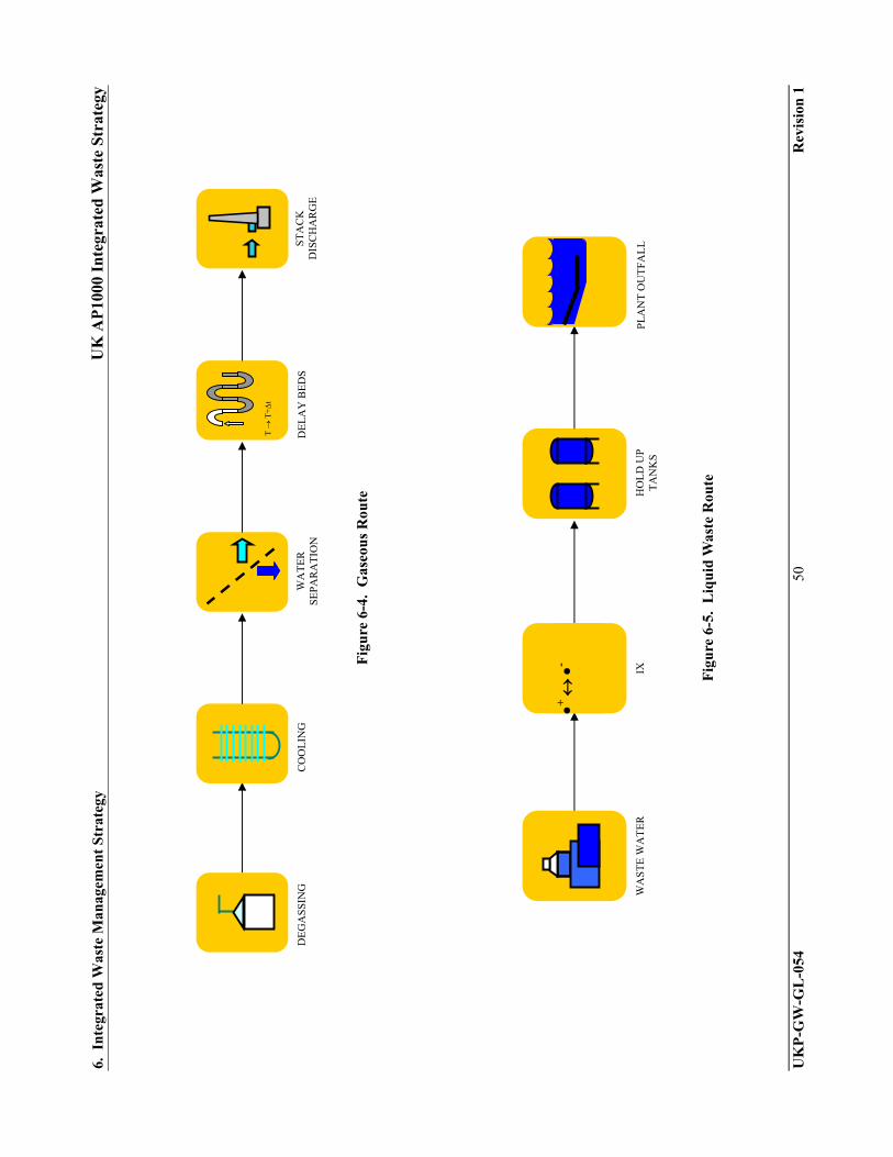
6. I
nte
grat
ed W
aste
Man
agem
ent
Str
ateg
y U
K A
P10
00 I
nte
grat
ed W
aste
Str
ateg
y
UK
P-G
W-G
L-0
54
50
Rev
isio
n 1
Fig
ure
6-4
. G
aseo
us
Rou
te
Fig
ure
6-5
. L
iqu
id W
aste
Rou
te
IX
WA
ST
E W
AT
ER
H
OL
D U
P
TA
NK
S
+
-
PL
AN
T O
UT
FAL
L
CO
OL
ING
D
EG
AS
SIN
G
DE
LA
Y B
ED
S
ST
AC
K
DIS
CH
AR
GE
T
T+
t
WA
TE
R
SE
PA
RA
TIO
N

6. I
nte
grat
ed W
aste
Man
agem
ent
Str
ateg
y U
K A
P10
00 I
nte
grat
ed W
aste
Str
ateg
y
UK
P-G
W-G
L-0
54
51
Rev
isio
n 1
Fig
ure
6-6
. L
ow L
evel
Was
te O
il R
oute
WA
ST
E O
IL S
TO
RA
GE
A
P10
00
OF
F S
ITE
IN
CIN
ER
AT
ION
C
OL
LE
CT
ION
W
AT
ER
S
EP
AR
AT
ION
C
OL
LE
CT
ION
WA
ST
E O
IL P
RO
CE
SSIN
Ge.
g. n
ocha
r
Not
e 1:
Was
te o
il th
at d
oes
not m
eet C
FA
for
inci
nera
tion
can
be
trea
ted
usin
g m
obile
sys
tem
s an
d so
lidif
ied;
e.g
., us
ing
‘noc
har’
fo
llow
ed b
y pa
ckag
ing
with
oth
er s
olid
LL
W w
aste
and
shi
pmen
t to
LL
WR
.
note
1

6. I
nte
grat
ed W
aste
Man
agem
ent
Str
ateg
y U
K A
P10
00 I
nte
grat
ed W
aste
Str
ateg
y
UK
P-G
W-G
L-0
54
52
Rev
isio
n 1
Fig
ure
6-7
. S
olid
In
term
edia
te L
evel
Was
te R
oute
FIL
TE
RS
RE
SIN
S
DR
UM
/BO
X
AP1
000
ON
SIT
E S
TO
RE
R
EP
OS
ITO
RY
IM
MO
BIL
ISE

6. I
nte
grat
ed W
aste
Man
agem
ent
Str
ateg
y U
K A
P10
00 I
nte
grat
ed W
aste
Str
ateg
y
UK
P-G
W-G
L-0
54
53
Rev
isio
n 1
Fig
ure
6-8
. S
pen
t F
uel
Rou
te
HA
ND
LIN
G
AP1
000
STO
RE
(F
UE
L
PO
ND
)
HA
ND
LIN
G
LO
AD
&
TR
AN
SP
OR
T
REPO
SITO
RY
ON
SIT
E S
TO
RE

6. I
nte
grat
ed W
aste
Man
agem
ent
Str
ateg
y U
K A
P10
00 I
nte
grat
ed W
aste
Str
ateg
y
UK
P-G
W-G
L-0
54
54
Rev
isio
n 1
Fig
ure
6-9
. D
ecom
mis
sion
ing
Inte
rmed
iate
Lev
el W
aste
Rou
te
ST
EE
L
IX
DR
UM
/BO
X
ON
SIT
E S
TO
RE
R
EP
OS
ITO
RY
IM
MO
BIL
ISE
AP1
000
+
-
CON
CRET
E
Res
in, F
ilte
rs
SIZ
E R
ED
UC
E
Wat
er

7. Areas Requiring Further Development and Action Plan UK AP1000 Integrated Waste Strategy
UKP-GW-GL-054 55 Revision 1
7. AREAS REQUIRING FURTHER DEVELOPMENT AND ACTION PLAN
This section will be developed further as the IWS is adopted by the utility operator. Those areas requiring further development are identified throughout the IWS and are summarised below:
Current and Future Status (subsection 2.2.8) Operational Milestones (subsection 2.2.9) Current Assumed Final End Point (subsection 2.2.10) Site Objectives (subsection 2.2.11) Waste Management Plans (subsection 3.1.7) Operator Strategy and Policies (subsection 3.1.9) Waste Management Organisation (Section 3.2) Waste Management Arrangements (Section 3.3) Methodology for Strategic Options Studies (Section 4.2) Site Prioritisation Logic (Section 4.3) Waste Management Constraints and Dependencies (Section 4.4) Site End Points and Contaminated Land (Section 4.5) Assumptions, Exclusions, Risks and Opportunities (Section 4.6) Stakeholder Engagement (Section 4.7)
An action plan describing the steps required to develop these areas will be developed by utility operators of the AP1000 NPP as this IWS is further defined during licensing and operation at a specific site.

8. Conclusions UK AP1000 Integrated Waste Strategy
UKP-GW-GL-054 56 Revision 1
8. CONCLUSIONS
This IWS has been prepared to address issues associated with the generic AP1000 NPP site. As identified above, there are many aspects that can be developed fully only at the specific site stage, taking into consideration the needs of particular stake holder groups, including AP1000 NPP operators. Where a specific element cannot be developed, salient features of the final requirement have been identified to aid future revisions of this IWS.
This IWS will continue to be developed through the remainder of the GDA process, through specific site licensing, through operation and finally during decommissioning. Alignment with the lifetime plan for an AP1000 NPP on a specific site will be incorporated along with changes in waste management techniques, technologies and regulatory requirements and strategies.

9. Glossary UK AP1000 Integrated Waste Strategy
UKP-GW-GL-054 57 Revision 1
9. GLOSSARY
This Glossary (Table 9-1) has been reproduced from [Ref. 2] with additions.
Table 9-1
GLOSSARY OF TERMS
Term Definition
AP1000 Type of light water reactor designed by Westinghouse Electric Company LLC, AP meaning “Advanced Passive.”
As Low As Reasonably Achievable (ALARA)
To satisfy the ALARA Principle, radiological doses and risks are kept as low as reasonably practicable, taking a proportionate approach, whereby priority is given to reducing discharges which have greatest radiological significance or which present most risk of damaging the marine environment, whilst ensuring that the costs of such reductions are not grossly disproportionate to their benefits in line with current Government guidance on better regulation.
As Low As Reasonably Practicable (ALARP)
To satisfy the ALARP Principle, measures necessary to reduce risk are undertaken until or unless the cost of these measures, whether in money, time, or trouble, is disproportionate to the reduction in risk.
Best Practicable Environmental Option (BPEO)
The waste management option which is the outcome of a systematic and consultative decision-making procedure which emphasises the protection and conservation of the environment across land, air, and water. The BPEO procedure establishes, for a given set of objectives, the option that provides the most benefit or least damage to the environment as a whole, at acceptable cost, in the long term as well as in the short term.
Best Practicable Means (BPM)
BPM is a term used by the Environment Agency and Scottish Environment Protection Agency in authorizations issued under the Radioactive Substances Act. Essentially, it requires operators to take all reasonably practicable measures in the design and operational management of their facilities to minimize waste creation, abating discharges, and monitoring plant discharges and the environment. It takes account of such factors as the availability and cost of relevant measures, operator safety, and the benefits of reduced discharges and disposals. If the operator is using BPM, radiation risks to the public and the environment will be As Low As Reasonably Achievable (ALARA).
BAT Best Available Technique
BDS AP1000 NPP Steam Generator Blowdown System
CCS AP1000 NPP Component Cooling Water System
CDS AP1000 NPP Condensate System
CFA Conditions for Acceptance
CFR U.S. Code of Federal Regulations
Cleanup Cleanup is the term we use in conjunction with Decommissioning. Once a nuclear facility has been decommissioned, the site needs to be cleaned-up to remove any possible contamination.

9. Glossary UK AP1000 Integrated Waste Strategy
UKP-GW-GL-054 58 Revision 1
Table 9-1
GLOSSARY OF TERMS (cont.)
Term Definition
Contaminated Land Contaminated land is defined as ground, soil, water and, potentially, underground structural materials such as building foundations which have been impacted by radioactive and/or chemical substances from past or present operations (including authorised discharges and disposals), and for which the level of the radioactive or chemical substance is above natural background.
Contaminated Groundwater
Contaminated groundwater is defined as water which has been impacted by radioactive and/or chemical substances from past or present operations (including authorised discharges and disposals), and for which the level of the radioactive or chemical substance is above natural background.
Committee on Radioactive Waste Management (CoRWM)
An independent committee appointed by the UK Government. Their task is to review the options for managing those UK radioactive wastes for which there is no agreed long-term solution.
CPS AP1000 NPP Condensate Polishing System
CVS AP1000 NPP Chemical and Volume Control System
CWS AP1000 NPP Circulating Water System
DCD European Design Control Document, Westinghouse document detailing the AP1000 NPP standard design
Disposal In the context of solid waste, disposal is the emplacement of waste in a suitable facility without intent to retrieve it at a later date. Retrieval may be possible but, if intended, the appropriate term is storage. Disposal may also refer to the release of airborne or liquid waste to the environment (i.e., emissions and discharges).
Decommissioning This is the process whereby a nuclear facility, at the end of its economic life, is taken permanently out of service.
Decontamination Removal or reduction of radioactive contamination
De-licensing The ending of the period of responsibility under the Nuclear Installations Act”. This is defined in Section 5(3) of the Nuclear Installations Act and can only happen when the HSE gives notice in writing to the licensee that in its opinion there has “ceased to be any danger from ionizing radiations from anything on the site or, as the case may be, on that part thereof.” This is generally equated with a risk of less than 1 in 106 P per year.
DTS Demineralised Water Treatment System
Environmental Impact Assessment
A process for the evaluation of the environmental effects of a project/development. As a result of Directive 85/337/EEC (as amended 1997) on the environmental assessment of certain projects Environmental Impact Assessment is now required as part of planning applications for major infrastructure projects.
Environmental Impact Assessment for Decommissioning
A process for the evaluation of the environmental effects of decommissioning nuclear reactors. As a result of Directive 85/337/EEC (as amended 1997) as implemented by the Nuclear Reactors (Environmental Impact Assessment for Decommissioning) Regulations 1999 the operators of nuclear reactors must apply to the Health and Safety Executive for consent to decommission nuclear reactors and requires environmental impact assessment of the decommissioning project.

9. Glossary UK AP1000 Integrated Waste Strategy
UKP-GW-GL-054 59 Revision 1
Table 9-1
GLOSSARY OF TERMS (cont.)
Term Definition
Environment Agency/EA
The Environment Agency’s role is the enforcement of specified laws and regulations aimed at protecting the environment, in the context of sustainable development predominantly by authorizing and controlling radioactive discharges and waste disposals to air, water (surface water, groundwater) and land. In addition to authorization issued under the Radioactive Substances Act 1993, the Environment Agency also regulates nuclear sites under the Pollution Prevention and Control Regulations and issues consents for non-radioactive discharges. The equivalent body in Scotland is the Scottish Environment Protection Agency (SEPA).
EU European Union
Euratom Within the European Union, nuclear matters are the subject of a separate treaty dating from 1957. This established the European Atomic Energy Community (EAEC) or EURATOM, which was set up to encourage progress in the field of nuclear energy.
Excluded An article or substance that is not radioactive under the Radioactive Substances Act 1993 (RSA 93) (and not subject to any control under the Act) because it does not contain levels of any of the specified radioelements above the limits in Schedule 1 of RSA 93 or any non-specified radioelements at levels above normal backgrounds. An excluded article or substance is unlikely to be subject to control as radioactive under other legislation
Exempt Wastes An article or substance that is radioactive or contaminated under the Radioactive Substances Act 1993 (RSA 93) because it contains levels of specified radioelements above RSA 93 Schedule 1 exclusion limits or because it contains other radioelements wholly or partly attributable to either an artificial process or as a result of the disposal of radioactive waste, but in both cases at levels below relevant limits in Exemption Orders under the Act. These exemptions are from the requirements of registration or authorisation under RSA 93. An (RSA) exempt article or substance may be subject to control as radioactive under other legislation (mostly due to the presence of exempt levels of RSA 93 Schedule 1 radioelements).
FSC Final Site Clearance
GDA Generic Design Assessment
GWD Giga-Watt Day (unit of energy)
Hazardous Waste Hazardous waste is controlled waste that contains any substance specified in The Hazardous Waste (England and Wales) Regulations 2005 and Equivalent Scottish Regulations. Radioactivity does not itself make waste hazardous waste. However radioactive waste may posses other properties, such a toxicity due to the presence of uranium, which bring it within the definition of hazardous waste and therefore subject to the requirements of the Hazardous Waste Regulations, in addition to the requirements of the Radioactive Substances Act 1993.
High Level Waste (HLW)
HLW is heat-generating waste. The temperature in HLW may rise significantly; this factor has to be taken into account when designing storage or disposal facilities.

9. Glossary UK AP1000 Integrated Waste Strategy
UKP-GW-GL-054 60 Revision 1
Table 9-1
GLOSSARY OF TERMS (cont.)
Term Definition
High Volume Low Activity Waste (HVLA)
A term not recognised in legislation but operationally used to identify wastes where the waste contains radioactivity that is only just above the legal limits which would otherwise allow the waste to be exempted from being LLW. HVLA waste is only just radioactive enough to be treated as a radioactive waste. This definition is used as a guide only and therefore is this guidance document has been used to label wastes within the lower activity areas of the LLW spectrum, which may be candidate for management in differently engineering solutions to those currently employed at the LLWR near Drigg. Additionally, the numerical level is not intended to be fixed and should be assessed on a case by case basis according to the mature of the LLW that may be managed differently. All proposals must be developed using risk based assessments to identify the material that falls into this category, for some wastes the specific activity may be lower and therefore require simpler engineering to manage the disposal, for other wastes the specific activity may be higher and assessed according to the performance of the facility it is intended to be disposed to.
HVAC Heating, Ventilation, and Air Conditioning System
Integration To be considered properly integrated a waste strategy must:
Demonstrate that the sites strategy for the management of wastes is consistent with relevant policy and strategy requirements (see Section 9) including:
– NDA’s Strategy and Annual Plans
– Radioactive waste management policy
– Non radioactive waste policy
– UK’s radioactive discharge strategy
– UK’s sustainable development strategy
Provide evidence that all “hand-offs” (transfers and receipts) of wastes are agreed between the sending and receiving sites, and for NDA sites, this agreement is reflected in both sites lifetime plans.
Identify uncertainties and assumptions and recognizing risks and opportunities within the strategy
Identify future investment needs for new waste management facilities and any research and development activities that need to be carried out to support the site IWS
Demonstrate a systematic approach to stakeholder engagement on waste management options and other waste issues.
Intermediate Level Waste (ILW)
Waste with radioactivity levels exceeding the upper boundaries for Low Level Waste (LLW) (Alpha – 4TBq/tonne or Beta/Gamma – 12BTBq/tonne activity), but which do not need heating to be taken into account in the design of storage or disposal facilities. ILW arises mainly from the reprocessing of spent fuel, and from general operations and maintenance of radioactive plant. The major components of ILW are metals and organic materials, with smaller quantities of cement, graphite, glass, and ceramics.
HEPA High Efficiency Particulate Air, type of filter of superior performance incorporated into HVAC and gas filtration systems.
HHISO Half Height ISO container, meeting low level waste repository CFA.
IAEA International Atomic Energy Agency
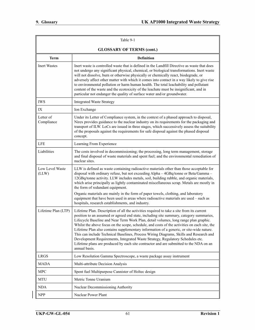
9. Glossary UK AP1000 Integrated Waste Strategy
UKP-GW-GL-054 61 Revision 1
Table 9-1
GLOSSARY OF TERMS (cont.)
Term Definition
Inert Wastes Inert waste is controlled waste that is defined in the Landfill Directive as waste that does not undergo any significant physical, chemical, or biological transformations. Inert waste will not dissolve, burn or otherwise physically or chemically react, biodegrade, or adversely affect other matter with which it comes into contact in a way likely to give rise to environmental pollution or harm human health. The total leachability and pollutant content of the waste and the ecotoxicity of the leachate must be insignificant, and in particular not endanger the quality of surface water and/or groundwater.
IWS Integrated Waste Strategy
IX Ion Exchange
Letter of Compliance
Under its Letter of Compliance system, in the context of a phased approach to disposal, Nirex provides guidance to the nuclear industry on its requirements for the packaging and transport of ILW. LoCs are issued in three stages, which successively assess the suitability of the proposals against the requirements for safe disposal against the phased disposal concept.
LFE Learning From Experience
Liabilities The costs involved in decommissioning; the processing, long term management, storage and final disposal of waste materials and spent fuel; and the environmental remediation of nuclear sites.
Low Level Waste (LLW)
LLW is defined as waste containing radioactive materials other than those acceptable for disposal with ordinary refuse, but not exceeding Alpha – 4GBq/tonne or Beta/Gamma – 12GBq/tonne activity. LLW includes metals, soil, building rubble, and organic materials, which arise principally as lightly contaminated miscellaneous scrap. Metals are mostly in the form of redundant equipment.
Organic materials are mainly in the form of paper towels, clothing, and laboratory equipment that have been used in areas where radioactive materials are used – such as hospitals, research establishments, and industry.
Lifetime Plan (LTP) Lifetime Plan. Description of all the activities required to take a site from its current position to an assumed or agreed end state, including site summary, category summaries, Lifecycle Baseline and Near Term Work Plan, detail volumes, long range plan graphic. Whilst the above focus on the scope, schedule, and costs of the activities on each site, the Lifetime Plan also contains supplementary information of a generic, or site-wide nature. This can include Technical Baselines, Process Wiring Diagrams, Skills and Research and Development Requirements, Integrated Waste Strategy, Regulatory Schedules etc. Lifetime plans are produced by each site contractor and are submitted to the NDA on an annual basis.
LRGS Low Resolution Gamma Spectroscope, a waste package assay instrument
MADA Multi-attribute Decision Analysis
MPC Spent fuel Multipurpose Cannister of Holtec design
MTU Metric Tonne Uranium
NDA Nuclear Decommissioning Authority
NPP Nuclear Power Plant
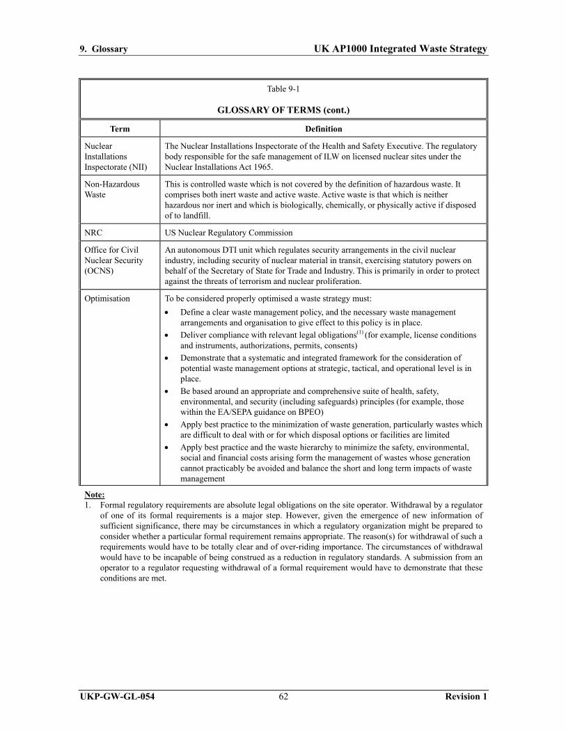
9. Glossary UK AP1000 Integrated Waste Strategy
UKP-GW-GL-054 62 Revision 1
Table 9-1
GLOSSARY OF TERMS (cont.)
Term Definition
Nuclear Installations Inspectorate (NII)
The Nuclear Installations Inspectorate of the Health and Safety Executive. The regulatory body responsible for the safe management of ILW on licensed nuclear sites under the Nuclear Installations Act 1965.
Non-Hazardous Waste
This is controlled waste which is not covered by the definition of hazardous waste. It comprises both inert waste and active waste. Active waste is that which is neither hazardous nor inert and which is biologically, chemically, or physically active if disposed of to landfill.
NRC US Nuclear Regulatory Commission
Office for Civil Nuclear Security (OCNS)
An autonomous DTI unit which regulates security arrangements in the civil nuclear industry, including security of nuclear material in transit, exercising statutory powers on behalf of the Secretary of State for Trade and Industry. This is primarily in order to protect against the threats of terrorism and nuclear proliferation.
Optimisation To be considered properly optimised a waste strategy must:
Define a clear waste management policy, and the necessary waste management arrangements and organisation to give effect to this policy is in place.
Deliver compliance with relevant legal obligations(1) (for example, license conditions and instruments, authorizations, permits, consents)
Demonstrate that a systematic and integrated framework for the consideration of potential waste management options at strategic, tactical, and operational level is in place.
Be based around an appropriate and comprehensive suite of health, safety, environmental, and security (including safeguards) principles (for example, those within the EA/SEPA guidance on BPEO)
Apply best practice to the minimization of waste generation, particularly wastes which are difficult to deal with or for which disposal options or facilities are limited
Apply best practice and the waste hierarchy to minimize the safety, environmental, social and financial costs arising form the management of wastes whose generation cannot practicably be avoided and balance the short and long term impacts of waste management
Note: 1. Formal regulatory requirements are absolute legal obligations on the site operator. Withdrawal by a regulator
of one of its formal requirements is a major step. However, given the emergence of new information of sufficient significance, there may be circumstances in which a regulatory organization might be prepared to consider whether a particular formal requirement remains appropriate. The reason(s) for withdrawal of such a requirements would have to be totally clear and of over-riding importance. The circumstances of withdrawal would have to be incapable of being construed as a reduction in regulatory standards. A submission from an operator to a regulator requesting withdrawal of a formal requirement would have to demonstrate that these conditions are met.

9. Glossary UK AP1000 Integrated Waste Strategy
UKP-GW-GL-054 63 Revision 1
Table 9-1
GLOSSARY OF TERMS (cont.)
Term Definition
Optimisation (cont.) Demonstrate that this framework for consideration of potential waste management options seek to identify synergies available from considering waste management options at site as well as project, process or plant level.
Demonstrate that this framework for consideration of potential waste management options transparently takes account of the full range of relevant principals and criteria.
Demonstrate that this framework for consideration of potential waste management options considers current and potential future interfaces with other sites where relevant.
Demonstrate that the framework for optimization incorporates a systematic approach to stakeholder engagement on waste management options and other waste issues.
Demonstrate the existence of an optimized strategy in line with the waste hierarchy for the management of all the wastes over the whole lifecycle of the site.
Describe the key reasons for selection particular waste management options within in the description of the sites strategy for each waste stream
Demonstration of a systematic approach to stakeholder engagement on waste management options and other waste issues.
Orphan Waste Materials for which no ‘final’ treatment or disposal route has yet been identified.
OSPAR The Oslo-Paris convention, which established requirements on the level of radioactive and non-radioactive discharges to the marine environment of the North East Atlantic, the North Sea, and the Irish Sea. The UK’s National Plan to implement its commitments under OSPAR with regard to radioactive substances is described within the UK Radioactive Discharge Strategy.
Passive Safety NII’s guidance to its inspectors defines passive safety in the following way:
“Passive safety requires radioactive wastes to be immobilized in a form that is physically and chemically stable and stored in a manner which minimizes the need for control and safety systems, maintenance, monitoring and human intervention. The wastes should be stored in discrete packages which are resistant to degradation and hazards and which can be inspected and retrieved for final disposal.”
Proximity Principle The proximity principle requires waste to be disposed of as close to the place of production as possible, taking account of all relevant factors. This principal aims to avoid passing the environmental costs of waste management to communities which are not responsible for its generation, and reduces the environmental costs of transporting waste. In considering waste management options there should be an assessment of where environmental burdens fall in relation to particular sectors of society and recognition of potential adverse impacts on health and quality of life, in relation to other potential benefits to the social and economic needs of the area.
Consideration needs to be given to balancing the impacts of waste transport against the concentration of radioactive wastes to ensure they can be securely and safely managed.
PWR Pressurised Water Reactor, type of light water reactor
POCO Post-Operational Clean Out
Radioactive Waste Any substance or article which, if it were not waste, would be radioactive material, or which has been contaminated in the course of the production, keeping or use of radioactive material, or by contact or proximity to other waste and for which no future use is foreseen.

9. Glossary UK AP1000 Integrated Waste Strategy
UKP-GW-GL-054 64 Revision 1
Table 9-1
GLOSSARY OF TERMS (cont.)
Term Definition
Radioactive Hazardous Waste
Radioactive waste which is also designated as hazardous waste due to its non-radioactive properties.
RFA Robust Fuel Assembly
RWMD Radioactive Waste Management Directorate
RWMC Radioactive Waste Management Case
SDS AP1000 NPP Sanitary Discharge System
Site End Point and Site End State
The “end state” of a site is the physical condition at the point when the NDA has finished UitsU business. The “end point” of a site is the time at which this ‘end state’ is reached. Site end states have previously been described as “Greenfield” or “Brownfield”. It is now accepted that these terms are not appropriate mainly because there is no agreed definition of what they mean and hence they cannot be recommended. It is likely that specific site end states will be defined as a result of a BPEO or an options study with appropriate stakeholder involvement.
Scottish Environment Protection Agency (SEPA)
The Scottish Environment Protection Agency’s role is the enforcement of specified laws and regulations aimed at protecting the environment, in the context of sustainable development predominantly by authorizing and controlling radioactive discharges and waste disposals to air, water (surface water, ground water), and land. In addition to authorization issued under the Radioactive Substances Act 1993, the Scottish Environment Protection Agency also regulates nuclear sites under the Pollution Prevention and Control Regulations and issues consents for non-radioactive discharges. The Scottish equivalent of the Environment Agency.
Sealed Source A ‘Sealed Source’ is a device in which a radioactive material has been contained within an outer casing. This outer casing makes an accidental release of the contents extremely unlikely. Sealed sources have an extensive range of medical, educational, and industrial uses, notably in general diagnosis and cancer treatments, and in the oil and gas industries.
Secondary Waste This is waste produced as a by-product of processing the primary waste stream.
Stakeholder Engagement
Proactive, open, and transparent communication with stakeholders ensuring there is ample opportunity to understand, comment on and influence strategies and plans. A stakeholder is defined as an individual or organization with a declared interest in the activities on a particular site. In the content of Integrated Waste strategy expectations for Stakeholder Engagement are covered Section 4.7 of this document and explored further in the Companion Document to the Integrated Waste Strategy Specification.
Storage Is the emplacement of waste in a suitable facility with the intent to retrieve it later.
Strategic Environmental Assessment (SEA)
A process for the evaluation of the environmental effects of a plan or program. Intended to asses an overarching framework covering multiple projects/developments (which may themselves require Environmental Impact Assessment). Directive 2001/42/EC requires the environmental assessment of certain plans and programmes.

9. Glossary UK AP1000 Integrated Waste Strategy
UKP-GW-GL-054 65 Revision 1
Table 9-1
GLOSSARY OF TERMS (cont.)
Term Definition
Sustainability – Sustainable Development
This has been widely defined as ‘development which meets the needs of the present without compromising the ability of future generations to meet their own needs. The following requirements should be met:
Waste management should not impose undue burdens on future generations and their environment such that it compromises their ability to meet their needs.
Even given a legacy of appropriate financial resources, future generations should preferably not have to divert time and effort to managing wastes generated by present and past generations.
They should be free to pursue their own preoccupations.
Decisions should be based on the best possible scientific information and analysis of risks
Where there is uncertainty and potentially serious risk exists, precautionary action may be necessary
Ecological impacts must be considered, particularly where resources are non-renewable or effects may be irreversible
The underlying principle of “polluter pays” should be recognized in assessing cost implications (the ‘polluter pays’ principle requires producers and owners of wastes to bear the costs imposed by those wastes, including the costs of regulation and those of related research undertaken both by themselves and by the regulatory bodies. The evaluation of environmental and human costs of waste production, treatment, and disposal should also be taken into account).
Sustainable development should be taken into account as one of the relevant considerations in considering the development of the Site IWS and of waste management policy.
SUDS Sustainable Urban Drainage System
SWMP Site Waste Management Plan
SWS AP1000 NPP Service Water System
TCS AP1000 NPP Turbine Closed Cooling System
UKAEA United Kingdom Atomic Energy Authority
Very Low Level Waste (VLLW)
Covers wastes with very low concentrations of radioactivity (less than 400 kBq of beta/gamma activity for each 0.1 m3 of material, or single items containing less than 40 kBq of beta/gamma activity). This waste arises from a variety of sources, including hospitals and the wider non-nuclear industry. Because VLLW contains little total radioactivity, it has been safely treated as it has arisen by various means, such as disposal with domestic refuse directly at landfill sites or indirectly after incineration.
VVM Spent Fuel Ventilated Vertical Module, Holtec storage design
VWS AP1000 NPP Central Chilled Water System

9. Glossary UK AP1000 Integrated Waste Strategy
UKP-GW-GL-054 66 Revision 1
Table 9-1
GLOSSARY OF TERMS (cont.)
Term Definition
Waste Hierarchy The Waste Hierarchy encourages the adoption of options for managing waste in the following order of priority:
Waste should be prevented or reduced at source as far as possible
Where waste cannot be prevented, waste materials or products should be reused directly or refurbished then reused
Waste materials should then be recycled or reprocessed into a form that allows them to be reclaimed as a secondary raw material
Where useful secondary materials cannot be reclaimed, the energy content of waste should be recovered and used as a substitute for non-renewable energy resources
Only if waste cannot be prevented, reclaimed, or recovered, should it be disposed of into the environment and this should only be undertaken in a controlled manner.
In addition to the Waste classification categories of LLW, ILW, HLW, and the like, waste types are considered to be the material forms of the waste within that category.
Waste Stream Nationally the inventory for the UK collated information on wastes by designated waste streams/waste stream identifiers which reflect the streams of waste generated or expected to be generated by operations or decommissioning. Over the years, this has tended to reflect whole lifetime wastes generated as LLW or from a particular location of facility.
By waste type, NDA refers to wastes grouped and therefore ‘labelled’ either by the method available to treat the waste or by the destination of that material, whichever applies to the LLW material identified; for example, asbestos, concrete, lead, mercury, copper, mild steel, stainless steel, mixed alloy, graphite, solvents/oils or organic incinerables/combustibles, putrescibles, soils, rubble, inorganics, flocculant, sludge, and raffinate.
WGS AP1000 NPP Gaseous Radwaste System
WLS AP1000 NPP Liquid Radwaste System
WSS AP1000 NPP Solid Radwaste System
WWRB AP1000 NPP Waste Water Retention Basin
WWS AP1000 NPP Waste Water System

10. References UK AP1000 Integrated Waste Strategy
UKP-GW-GL-054 67 Revision 1
10. REFERENCES 1. ENG01, “Specification for the Content and Format of a Site Integrated Waste Strategy Document,”
NDA.
2. ENG02, “Companion Document to Integrated Waste Strategy Specification,” NDA.
3. EPS-GW-GL-700, Rev. 1, “AP1000 European Design Control Document,” Westinghouse Electric Company LLC, 2009.
4. UKP-GW-GL-790, Rev. 4, “UK AP1000 Environment Report,” Westinghouse Electric Company LLC, 2011.
5. UKP-GW-GL-055, Rev. 2, “UK AP1000 Radioactive Waste Management Case Evidence Report for Intermediate Level Waste,” Westinghouse Electric Company LLC, 2011.
6. UKP-GW-GL-056, Rev. 2, “UK AP1000 Radioactive Waste Management Case Evidence Report for High Level Waste,” Westinghouse Electric Company LLC, 2011.
7. APP-GW-GER-005, Rev. 1, “Safe and Simple – The Genesis and Development of the AP1000 Design,” Westinghouse Electric Company LLC, 2008.
8. UKP-GW-GL-795, Rev 0, “UK AP1000 NPP Decommissioning Plan,” Westinghouse Electric Company LLC, 2011.
9. UKP-GW-GL-026, Rev 2, “AP1000 Nuclear Power Plant BAT Assessment,” Westinghouse Electric Company LCC, 2011.
10. LL 10568935, “GDA Disposability Report for the AP1000,” NDA, July 2009.
11. “Waste Strategy for England 2007,” DEFRA 2007.
12. “National Waste Plan 2003” (Scotland).
13. “Wise About Waste: The National Waste Strategy for Wales.”
14. Statutory Instruments 2008 No. 314, “The Site Waste Management Plans (SWMP) Regulations,” 2008.
15. UKP-GW-GL-027, Rev. 1, “Radwaste Waste Arisings, Management and Disposal,” Westinghouse Electric Company LLC, 2011.
16. EGR029, “The NDA Prioritisation Process: Assessment and Sensitivity Testing of the SED Measure and Project Benefit Measure Models.”
17. UKP-GW-GL-085, Rev. 0, “Long Term Storage of AP1000 NPP ILW and Spent Fuel in the UK,” Westinghouse Electric Company LLC, 2011.
18. “The Management of Higher Activity Radioactive Waste on Nuclear Licensed Sites – Radioactive Waste Management Cases,” HSE, EA, SEPA, November 2008 (version for comment and trial).
19. IAEA-TECDOC-1478, “Selection of Decommissioning Strategies: Issues and Factors,” IAEA, November 2005.
20. UKP-GW-GL-084, Rev. 0, “UK AP1000 NPP Decontamination Considerations,” Westinghouse Electric Company LLC, 2011.