Embed Size (px)
Citation preview
I. L. 43-250-!J
Westinghouse --25 LINE-
SWITCHBOARD INSTRUMENTS
SIX-INCH CLASSIFICATION
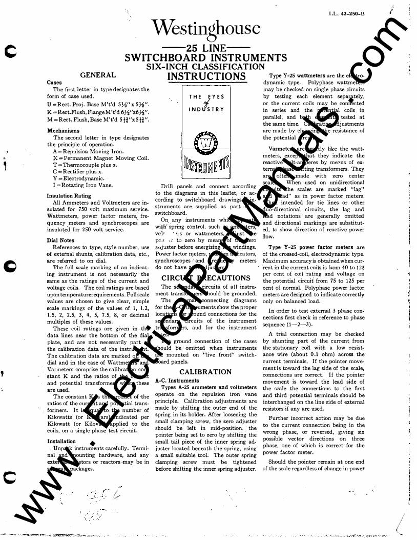
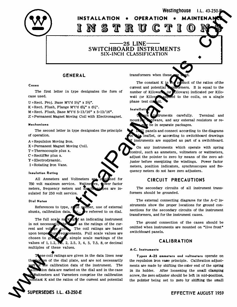
GENERAL Cases
The first Jetter in type designates the
form of case used.
U =Rect. Proj. Base M't'd 572" x 572".
K =Rect.Flush,FiangeM't'd 672"x672"· M =Rect. Flush,Ba�e M't'd 5H"x 5H"·
Mechanisms The second letter in type designates
the principle of operation. A =Repulsion Moving Iron. X= Permanent Magnet Moving Coil. T =Thermocouple plus x. C =Rectifier plus x. Y =Electrodynamic. I =Rotating Iron Vane.
Insulation Rating All Ammeters and Voltmeters are in
sulated for 750 volt maximum service. Wattmeters, power. factor meters, frequency meters and synchroscopes are insulated for. 250 volt service.
Dial Notes References to type, style number, use
of external shunts, calibration data, etc., are referred to on dial.
The full scale marking of an indicating instrument is not necessarily the same as the ratings of the current and voltage coils. The coil ratings are based upon temperaturerequirements. Full scale values are chosen to give clear, simple scale marl.::ings of the values of 1, 1.2, 1.5, 2, 2.5, 3, 4, 5, 7.5, 8, or decimal multiples of these values.
These coil ratings are given in the data lines near the bottom of the dial plate, and are not necessarily part of the calibration data of the instrument. The calibration data are marked on the dial and in the case of Wattmeters and Varmeters comprise the calibration constant K and the ratios of the current and potential transformers when these are used.
The constant K is the product of the ratios of the current and potential transfvrmers. It is eq).lal to the number of Kilowatts (or Kilovars) indicated per Kilowatt (or Kiiovar) applied to the coils, on a single phase te.o;t circuit.
Installation
Cnr'ack instrum('nts carefully. Tem�inal and mounting han:i"·are, and any external r�sistors or reactors may be in separaie packages.
INSTRUCTIONS
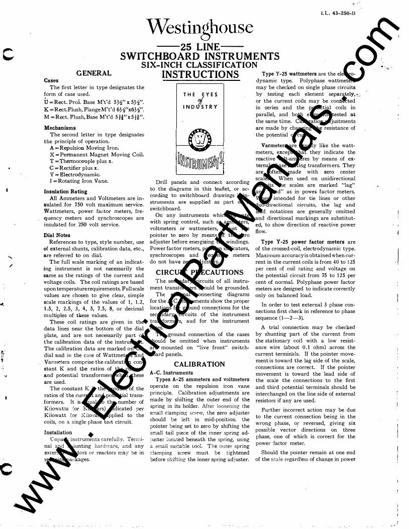
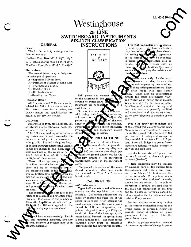
T H E E Y E S IN Dts T R Y
Drill panels and connect according to the diagrams in this leaflet, or according to switchboard drawings if instruments are supplied as part of a switchboard.
On any instruments which operate with spring control, such as ammeters, voltmeters or wattmeters, adjust the pointer to zero by means of the zero adjuster before energizing the windings. Power factor meters, position indicators, synchroscopes and frequency meters do not have zero adjusters.
CIRCUIT PRECAUTIONS The secondary circuits of all instru
ment transformers should be grounded. The external connecting diagrams
for the A-C. instruments show the proper locations for ground connections for the secondary circuits of the instrument transformers, aud for the instrument cases.
The ground connection of the cases should be omitted when instruments are mounted on "live front" switchboard panels.
CALIBRATION A-C. Instruments
Types A-25 ammeters and voltmeters
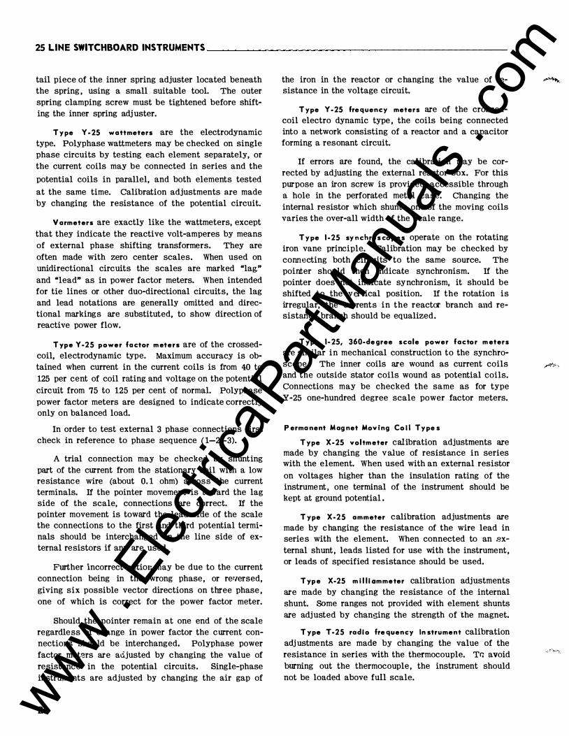
operate on the repulsion iron vane principle. Calibration adjustments are made by shifting the outer end of the spring in its holder. After loosening the small clamping screw, the zero adjuster should be left in mid-position, the pointer being set to zero by shifting the small tail piece of the inner spring ad_;uster located beneath the spring, using a small suitable tool. The outer spring clamping screw must be tightened before s.hifting the in.r1er spring adjuster.
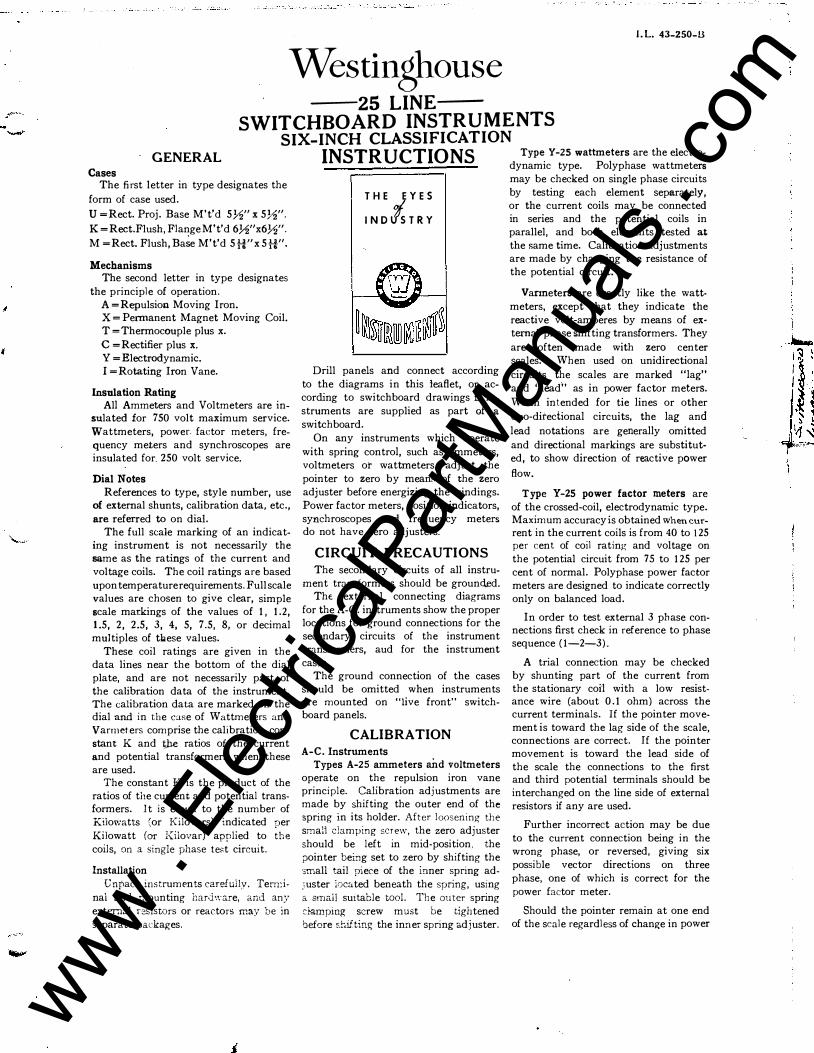
Type Y-25 wattmeters are the electrodynamic type. Polyphase wattmeters may be checked on single phase circuits by testing each element separately, or the current coils may be connected in series and the potential coils in parallel, and both elements tested at the same time. Calibration adjustments are made by changing the resistance of the potential circuit.
Vanneters are exactly like the wattmeters, except that they indicate the reactive volt-amperes by means of external phase shifting transformers. They are often made with zero center scales. When used on unidirectional circuits the scales are marked "lag" and "lead" as in power factor meters. When intended for tie lines or other duo-directional circuits, the lag and
lead notations are generally omitted and directional markings are substituted, to show direction of reactive power
flow.
Type Y -25 power factor meters are of the crossed-coil, electrodynamic type. Maximum accuracy is obtained when current in the current coils is from 40 to 125 per cent of coil rating and voltage on the potential circuit from 75 to 125 per cent of normal. Polyphase power factor meters are designed to indicate correctly only on balanced load.
In order to test external 3 phase connections first check in reference to phase sequence (1-2-3).
A trial connection may be checked by shunting part of the current from the stationary coi·l with a low resistance wire (about 0.1 ohm) across the current terminals. If the pointer movement is toward the lag side of the scale, connections are correct. If the pointer movement is toward the lead side of the scale the connections to the first and third potential terminals should be interchanged on the line side of external resistors if any are used.
Further incorrect action may be due to the current connection being in the wrong phase, or reversed, giving six possible vector directions on three phase, one of which is correct for the power factor meter.
Should the pointer remain at one end of the scale regardless of change in power
www . El
ectric
alPar
tMan
uals
. com
i I I
�·
factor the current connections should be interchanged. Polyphase power factor meters are adjusted by changing the value of resistance in the potential circuits. Single-phase instruments are adjusted by changing the air gap of the iron in the reactor or changing the value of resistance in the voltage circuit.
Type Y-25 frequency meters are of the crossed-coil electro dynamic type, the coils being connected into a network consisting of a reactor and a capacitor forming a resonant circuit.
If errors are found, the calibration may be corrected by adjusting the external reactor box. For this purpose an iron screw is provided, accessible through a hole in the perforated metal case. Changing the internal resistor which shunts one of the moving coils
varies the over-all width of the scale
range.
Type 1-25 synchroscopes operate
on the rotating iron ·;ane principle.
Calibration may be checked by con
necting both circuits to the same source.
The pointer should then indicate _sy�
chronism. If the pointer does not :ndt
cate synchronism, it should be shtf�ed
to the vertical position. If the rotatiOn
is irregular, the currents in tht reactor
branch and resistance branch should
be equalized.
Type 1-25, 360-degree scale power factor meters are similar in mechanical construction to the synchroscope. The inner coils are wound as current coils and the outside. stator coils wound as potential coils. Connections may be checked the same as for type Y-25-one hundred degree scale power factor meters.
Type 1-25 position indicators are similar in mechanical construction to
the synchroscope, the electrical characteristics being different. Leads must be connected in the proper sequence to have the indicator follow the controller properly in the right direction.
Permanent Magnet Moving Coil Types Type X-25 voltmeter calibration ad
justments are made by changing the value of resistance in series with the element. When used with an external resistor on voltages higher than the in� su!ation rating of the instrument, one terminal of the instrument should be kept at ground potential.
Type X-25 ammeter calibration adjustments are made by changing the resistance of the wire lead in series with the element. When connected to an external shunt, leads listed for use with the instrument, or leads of specified resistance should be used.
Type X-25 milliammeter calibration adjustments are made by changing the resistance of the internal shunt. Some ranges not provided with element shunts are adjusted by changing the strength of the magnet.
Type T-25 radio frequency instrument calibration adjustments are made by changing the value of the resistance in series with the thermocouple. To avoid burning out the thermocouple, the instrument should not be loaded above full scale.
Radio frequency instruments have the left terminal, as viewed from the rear bonded to the metal chassis and dial
' of the instrument. This prevents
electrostatic effects between pointer and dial and provides points of zero potential inside the instrument.
Radio frequency instruments, particularly when operated from external thermocouples, should be arranged with effective R.F. ·by-pass and ground connections to minimize the effect of capacity currents.
Type C-25 rectifier type voltmeter calibration adjustments are made by changing the value of series resistance. Rectifier type milliammeters are calibrated by changing the strength of the magnet. Rectifier type instruments indicate correctly at 25C. with 60 cycle pure sine wave.
REPAIRS AND RENEWAL PARTS
Repair work can be done most satisfactorily at the factory. When returning an instrument for repairs, obtain a returned material tag from your dealer or your nearest Westinghouse Sales Office to assure proper identification at the factory.
Orders for renewal parts should include the name of the part and the style and serial number of the instrument, appearing on the dial.
Spare Lamps Internally illuminated instruments
use jji46 Mazda Lamps (6.3 volts 0.25 amp.) Westinghouse Style No. 1,001,663. These are rated at 3000 hour life at rated voltage. 10 percent overvoltage greatly decreases life.
For 110 to 140 volts, Type MT miniature transformer, Style iii 1246352 (6.3 volt secondary) is available.
Special Notes For 3 element A-25 instruments, tem
perature indicators, Z-25 D-C. Wattmeters or for special instruments, see separate leaflets.
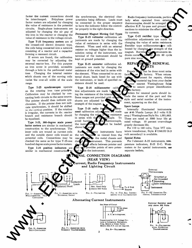
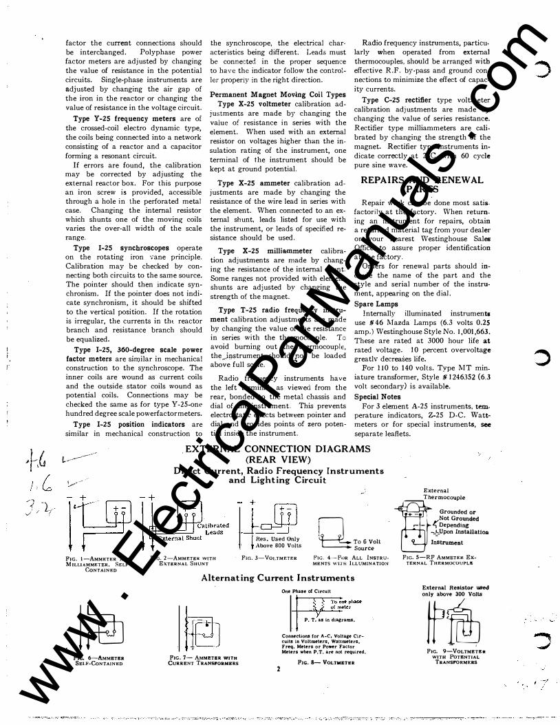
EXTERNAL CONNECTION DIAGRAMS (REAR VIEW)
FIG. I-AMMETER AND MILLIAMMETER, SELF
CoNTAINED
l�
FIG. 6-AMMETER SELF-CoNTAINED
Direct Current, Radio Frequency Instruments and Lighting Circuit
FIG. 2-AMMETER WITH EXTERNAL SHUNT
Res. Used Only Above BOO Volts
FIG. 3-VOLTMETER
n To6Volt �Source
FIG. 4-FoR ALL lNSTRU· MENTS \\'Jl H ILLUMINATION
Alternating Current I nstruments
F1G. 7- AMMETRR WITH CuRRENT TRANSFORMERS
2
One Phase of Circuit
� To one phase <t. • o( meter
P, T. as in diagrams.
Connections for A-C. Voltage Circuits in Voltmeters, Wattmeters, Freq. Meters or Power Factor Meters when P. T. are not required.
F1G. s- VoLTMETER
External
J
Ther
:::::
l
:d or #" Not Grounded ; Depending
--':-Upon Installation Instrument
FIG. 5-RF AMMETER ExTERNAL THERMOCOUPLE
External Resistor used only above 300 Volts
w� FtG. 9-VOLTMETRR
WITH PoTENTIAL TRANSFORMERS
www . El
ectric
alPar
tMan
uals
. com

I'
c
•
c
ALTERNATING CURRENT INSTRUMENTS-Continued
ADS Transmitter
M3
T2 Used only above
150 Volts :�:i=======t: Single Phase A-C. Supply
Controller
FIG. 10- POSITION INDICATOR
External Resistor used
f�TI��� (Complete connections I to I, 3 to 3 before connecting to U.ne)
FIG. 12-FREQUENCY METER
3 2 1
External Resistor used only above 300 Volts
m FIG. 13-WATTMETER,
SINGLE PHASE
Type Y -25 requires external resistors to lines 1 and 3 for voltages above 300 only. Below 300 no external resistors are used, Type 1-25 requires 3 external resistors as shown
I in this diagram.
FIG. 16-PowER FACTOR METER, 3 PHASE, 3-WIRE
External Resistor used 8 3 2 I only above 300 Volts
FIG. IS-WATTMETER, 3- PHASE, 4-WIRE (Y.C.T.)
0 3 2
8 82 External Resistor used AI A2 only above 300 Volts
FIG. 19-WATTMETER, 2-PHASE, 4-WIRE
FIG. 21-VARMETER 3-PHASE. 4-WIRK
Standard Phase Rotation (1-2-3) used.
3
--11--":;....,e--+=� Inc. ��-------+----- Run ________ ..._ ____ Common
FIG. 11-SYNCHROSCOPE
External Resistor used
3 2 1 only above 300 Volts
FIG. 14-WATTMETER, 3 PHASE, 3 WIRE
FIG. IS-PowER FACTOR MKTER, SINGLK PHASE
2
3 2 1
Std. Polyphase wattmeter
For resistors used see Fig, 14 and 1 6
Polyphase Power Factor Meter when used with 2 Current Transformers as used for Wattmeter
FIG. 17-c "' YPHASE WATTMETER
3 2 1
AND Po .c)<J< FACTOR METER
Phase Shifting Transformer
For 0-Lag Scale Reverse Current Coil Connections
,->'lr;:;;:H-:;Fiil
FIG. 20-VARMETER, 3-PHASE, 3-WIRE
Ftc. 22-VARMETER., SINGLE PHASE-2 WIRE
www . El
ectric
alPar
tMan
uals
. com
)
r i
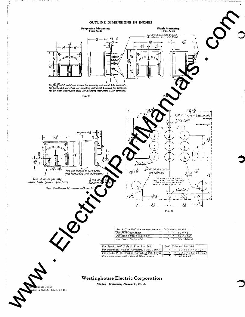
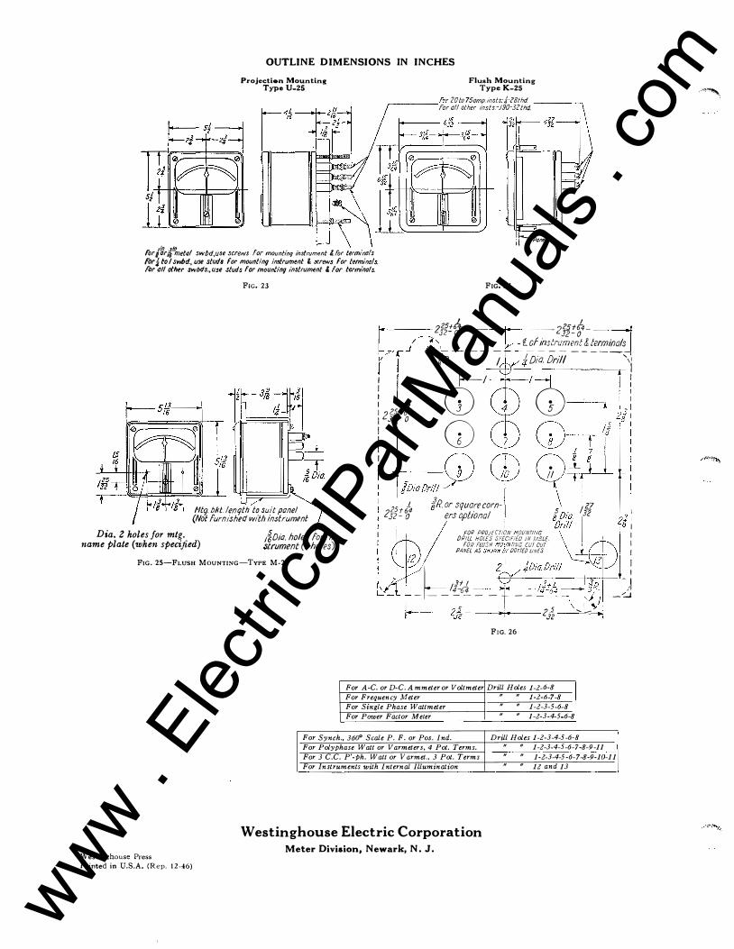
OUTLINE DIMENSIONS IN INCHES
Projection Mounting Type U-25
i.-J
Flush Mounting Type K-25
For 20 to 75amp.insts:{c8thd r-----For all other lnsts.-.190-32 thd. -----,
;r-Prtn</ For/'ir,//&etal swbd.,u3e screws for mounting insfrum1nt 'for terminals For:/ to I swbd., u3e studs for mounting in•frument &. screws for terminals. Fl)f' all othtr swbds., use studs for mounting instrument ' for terminol•.
FIG. 23
jo,obd/J£i) Htq. bkt /enqth to suit pone/
(Not fum!shect with instrument 1 81Rorsquarecorn-2l?t64
1 Jz- o ers opt/on a/ Dia. 2 holes for mtg.
name plate (when specified) Joio holes for in.3trument (2 holes)
FIG. 25-FLusu MouNTING-TYPE M-25
I I I I I I
Westinghouse Press Printed in U.S.A. (Rep. 12.48)
�' L-
FIG. 26
For A-C. or D-C. Ammeter or Voltmeter! Drill Holes 1-2-6-8
For Frequency Meter I " • 1-2-6-7-8
For Single Phase Wattmeter " " 1-2-3-5-6-8
For Po·wer Factor ;weter I " " 1-2-3-4-5-6-8
.-------------------------------�---------------------For Synch., 360" Scale I'. F. or Pos. Ind. Drill Holes 1-2-3-4-5-6-8
For Polyphase Watt or Varmeters, 4 Pot. Terms. • 1-2-3-4-5-6-7·8 .. 9-11
For 3 C.C. P'-ph. Watt or Varmet . . 3 Pot. Terms 1-2-3-4-5-6-7-8-9-10-11
For Instruments UJith Internal lllumination 12 and 13
Westinghouse Electric Corporation Meter Division, Newark, N. J.
\
www . El
ectric
alPar
tMan
uals
. com

/ /
! I r l I ._,�-
.\
;1§ 32 T
OUTLINE DIMENSIONS IN INCHES
Projection Mounting Type U-25
t..J
Flush Mounting Type K-25
fOr 20 to 75amp.insts.�J�c8tM. r------l'or all other insts.-.190-32thti. -----.,
ForJ�r,1�metol swbd.,use screws for mounting instrument &for termimtls FIJI'J to I swbd., u•e stu<lo for mountln9 instrument l screws for ttrminal•. For all other swtxls., use stud• for mounting instrument ' for terminols.
.._,_, il
FIG. 23
11tq bkt. !enqth to suit pone/ (Not furmshed with instrument
F1G.24
\ \ D 2·25+&. 225 +14 Je- 0 .JZ-0 ;--L _ -- _ _t!_!�sf!��t�'!_I!!!/�S-;
I/ / r jR. I 'Dia. Or;// ,,, ! I 1---' '--1 : ! 2"'4 G) G) ! ) I .Jz-0 r-. (:\ /Q 8 I
l \1) \j_J-----r 18 : : � �il : . p it ��- i ,;,.{ /R'"'"'r'"m- , . 1ZZ � ; 2Jz- o ers opbona
/ 8 O(a. l32 2J 1 Dr;!/ ,8 I
Dia. Z holes for mtg. name p/ate (when specified) if;Dio. holes for in
�frument (2 holes)
FOil PPOJECTION MOUNTING DRilL HOLES SPECIFIED IN TABLE.
FOR FWSH !10UNriNG CUr Our PANEL AS SHOWN BY OOT!£0 LINES
FIG. 25-FLUSH MouNTING-TYPE M-25 2
'-----2/2 2/2 ' oo1 FIG. 26
For A·C. or D-C. Ammel.r or Voltmeter! Drill Holes 1-2-IJ-8 For Frequency Metlr • • 1-2-IJ-7-8 For Single Phase Wattmeter • • 1-2-3-5-6-8 For Power factor Meter • • 1-2-3-4-5-6-8
For Polyphase Wall or Varmeters, 4 Pot. Terms. • • 1-2-3-4-5-6-7-8-9-11 For 3 C.C. P'-ph. Wall or Varmel., 3 Pot. Terms • • 1-2-3-4-5-6-7-8-9-10-11
'
\ \ I. � · ' /'-t c
For Synch., 360" Scale P. F. or Pos. Ind.
I Drill Holes 1-2-3-4-5-6-8
Far Instruments with Internal Illumination 11 " 12 and 13
< ' ,/
Westinghouse Press Printed io U.S.A. (Rep. 12-48)
( . \.._.' '
Westinghouse Electric Corporation Meter Division, Newark, N.J.
I� _.--r
.'
J :/r , . . � ...
\.. )
\.
J
J
............ _)
........ _ ,,�r---·- ...,....,_,_,___,,....,� --.,..,.-·-�17.f"�.--.. -,-< ,-.:.,. - ��-;'<•< .,�·-j"',,J. 1'•�-t .. ":lf�,.-;;;;,"�·'"·�� .. , � ·· . �-�-......J www . El
ectric
alPar
tMan
uals
. com

c
c
;'\ '..._. - /
c I
I j
ALTERNATING CURRENT INSTRUMENTS-Continued
ADS Transmitter
M3
T2 Used only above
-- 150 Volts
i 1 T 1 Single Phase
Controller A-C. Supply
FIG. tO- PosiTION INDICATOR
External Resistor used fonly�a7ve !50 V:ltS
External
. � Reactor Sax
. ' 3 (Complete connections 1 to 1, 3 to 3 before connecting to lkle)
FIG- 12-FREQUENCY METER
3 2 1
External Resistor used only above 300 Volts
m FIG. 13-WATTMETRR,
SINGLE PHASE
Type Y -25 requires external' resistors to lines 1 and 3 for voltages above 300 only. Below 300 no external resistors are used. Type I-25 requires 3 external resistors as shown
1 in this diagram.
FIG. 16-POWER FACTOR METER, -� PHASE, 3-WIRE
External Resistor used I 3 2 1 only above 300 Volts
-:-FIG. IS-WATTMETER, 3-PHASE, 4-
WtRE (Y.C.T.)
0 3 2
Bt B2 Externa l Resistor used
AI A21 only above 300 Volts
FIG. 19-WATTMETER, 2-PHASE, 4-WtRE
FIG. 21-VARMETER 3-PHASE. 4-WIRE
Standard Phase Rotation (1-Z-3) used.
3 r
"1 n 1--·
�' ---.
_...1 ..... --·---+1--'- ��� Common
FIG. 11-SVNCHROSCOPE
External Resistor used
3 2 1 only above 300 Volts External Resistor ftjuse�
5�n�
0��ove
L External Reactor
L Box
FIG. 14- Vir.,ATTMETER. 3 PHASE, 3 WtRE
FrG. IS-PoWER FACTOR METER, SINGLE PHASE
2
!
, (-I . '
3 2 1
Std. Polyphase waittnetet·
For resistors used see Fig, 14 and 1 6
•
Polyphase Power Factor Meter wJ>Rn>"sed with? Current Transformers as used for Wattmeter
FIG. 17--1·· ·.\"PHASE WATTMETER At'D r'OW,.R FACTOR MEIER
3 2 l Phase Shifting Transformer � For 0-Lag Scale Reverse � Current Coil Connections
FIG. 20-VARMETER, 3-PHASK, 3-WIRE
FIG. 22-V ARMETE!l, SiNGLE PHASE-2 WJ!lE
' r· \
\
\ \ \
( I .
. /
\ \ '\\
�
�· ',
>.,
www . El
ectric
alPar
tMan
uals
. com
r
ih� I I /rG
� { -""/L I
factor the current connections should be interchanged. Polyphase power factor meters are adjusted by changing the value of resistance in the potential circuits. Single-phase instruments are adjusted by changing the air gap of the iron in the reactor or changing the value of resistance in the voltage circuit.
Type Y-25 frequency meters are of the crossed-coil electro dynamic type, the coils being connected into a network consisting of a reactor and a capacitor forming a resonant circuit.
If errors are found, the calibration may be corrected by adjusting the external reactor box. For this purpose an iron screw is provided, accessible through a hole in the perforated metal case. Changing the internal resistor which shunts one of the moving: coils varies the over-all width of the scale range.
Type 1-25 synchroscopes operate on the rotating iron ·;ane principle. Calibration may be checked by connecting both circuits to the same source. The pointer should then indicate synchronism. If the pointer does not indicate synchronism, it should be shifted to the vertical position. If the rotation is irregular, the currents in tht reactor branch and resistance branch should be equalized.
Type 1-25, 360-degree scale power factor meters are similar in mechanical construction to the synchroscope. The inner coils are wound as current coils and the outside. stator coils wound as potential coils. Connections may be checked the same as for type Y-25-one hundred degree scale powerfactormeters.
Type 1-25 position indicators are similar in mechanical construction to
the synchroscope, the electrical characteristics being different. Leads must be connected in the proper sequence to have the indicator follow the controller properiy in the right direction.
Permanent Magnet Movmg Coil Types Type X-25 voltmeter calibration ad
justments are made by changing the value of resistance in series with the element. When used with an external resistor on voltages higher than the insulation rating of the instrument, one terminal of the instrument should be kept at ground potential.
Type X-25 ammeter calibration adjustments are made by changing the resistance of the wire lead in series with the element. When connected to an external shunt, leads listed for use with the instrument, or leads of specified resistance should be used.
Type X-25 milliammeter calibration adjustments are made by changing the resistance of the internal shunt. Some ranges not prov;ded with element shunts are adjusted by changing the strength of the magnet.
Type T-25 radio frequency instru
ment calibration adjustments are made by changing the value of the resistance in series with the thermocouple. To avoid burning out the thermocouple, the..Jnstrument should ,rot be loaded above full scale. ' '
Radio frequency instruments have the left terminal, as viewed from the rear, bonded to the metal chassis and dial of the instrument. This prevents electrostatic effects between pointer and dial and provides points of zero potential inside the instrument.
Radio frequency instruments, particularly when operated from external thermocouples, should be arranged with effective R.F. by-pass and ground connections to minimize the effect of capacity currents.
Type C-25 rectifier type voltmeter calibration adjustments are made by changing the value of series resistance. Rectifier type milliammeters are calibrated by changing the strength of the magnet. Rectifier type instruments indicate correctly at 25C. with 60 cycle pure sine wave.
REPAIRS AND RENEWAL PARTS
Repair work can be done most satiSfactorily at the factory. When returning an instrument for repairs, obtain a returned material tag from your dealer or your nearest Westinghouse Sales Office to assure proper identification at the factory.
Orders for renewal parts should include the name of the part and the style and serial number of the instrument, appearing on the dial.
Spare Lamps
Internally illuminated instruments use #46 Mazda Lamps (6.3 volts 0.25 amp.) Westinghouse Style No. 1,001,663. These are rated at 3000 hour life at rated voltage. 10 percent overvoltage greatlv decreases life.
For 110 to 140 volts. Type MT miniature transformer, Style #1246352 (6.3 volt secondary) is available.
Special Notes
For 3 element A-25 instruments, temperature indicators, Z-25 D-C. Wattmeters or for special instruments, see
separate leaflets.
�....------EXTERNAL CONNECTION DIAGRAMS
(REAR VIEW)
'r-'/ Direct Current, Radio Frequency Instruments
and Lighting Circuit .. ·
l�F ., Res. Used Only Above 800 Volts QTo6Vo" Source
FIG. 1-AMMETER AND M ILLIAMMETER, SKLF
CONTAINED
I� FIG. 6-AMMETER SE!.F-CoNTAINED
FIG. 2-AMMETER W(TH EXTERNAL SHUNT
FIG. 3-VOLTMETER PtG. 4-Fc::)R ALL INSTRUMENTS WITH lLLUMINATIO!'l'
Alternating Current Instruments
t9 Ftc. 7- AMMI!TER wnu
CuRRENT TRANSJI'ORMBRS 2
One Phase of Circuit
P. T. as tn diagrams.
Connections for A�C, Voltage Circuits In Voltmeters, Wattmeters, Freq, Meters or Power ·Factor Meters when P. T. are not required.
Frc. 8- VoLTMETI!R
\,"<,,-;o-;-,-,�:,--;-.-
External
J
Ther::::::�:
or Not Grounde
d !(Depending --�Upon Installation Inst
rument
Fie. 5-RF AMMETER ExTERNAL THERMOCOUPLK
External Resistor used only above 300 Volts
Wtfu FIG. 9-VOLTMETER
WITH POTENTIAL TRANSFORMERS
�
�
�
www . El
ectric
alPar
tMan
uals
. com
� !GL4$C ,_, ___ _
c
. , ,
Q
'
c
l.L. 43-250-B
Westinghouse --25 LINE-
SWITCHBOARD INSTRUMENTS SIX-INCH CLASSIFICATION
GENERAL Cases
The first Jetter in type designates the form of case used.
U =Rect. Proj. Base M't'd 5Y:;" x 5Y:;".
K =Rect.Flush, FlangeM't'd 6Yl;"x6Yl;". M =Rect. Flush,Ba�e M't'd 5fi"x5fi".
Mechanisms The second letter in type designates
the principle of operation. A =Repulsion Moving Iron. X=Permanent Magnet Moving Coil . T =Thermocouple plus JL C =Rectifier plus x. Y =Electrodynamic. I =Rotating Iron Vane.
Insulation Rating All Ammeters and Voltmeters are in
sulated for 750 volt maximum service. Wattmeters, power. factor meters, frequency meters and synchroscopes are insulated for 250 volt service.
Dial Notes References to type, style number, use
of external shunts, calibration data, etc., are referred to on dial.
The fnll s;cale marking of an indicating instrument is not necessarily the same as the ratings of the current and voltage coils. The coil ratings are based upon temperaturerequirements. Full scale values are chosen to give clear, simple scale markings of the values of 1, 1.2, 1.5, 2, 2.5, 3, 4, 5, 7 .5, 8, or decimal multiples of these values.
These coil ratings are given in the data lines near the bottom of the dial plate, and are not necessarily part of the calibration data of the instrument. The calibration data are marked on the dial and in the case of Wattmeters and Varmeters comprise the calibration constant K and the ratios of the current and potential transformers when these are used.
The constant K is the product of the ratios of the current and potential transformers. It is equal to the number of Kilowatts (or Kilovars) indicated per Kilowatt (or Kilovar) applied to the coils, on a single phase test circuit.
Installation Unpack instruments carefully. Termi
nal and mounting hardware, and any external resistors or reactors--may be in separate packages.
e� !". I � ' {r-
',._ / .
INSTRUCTIONS
T H E EYE S IN Dts T R Y
Drill panels and connect according to the diagrams in this leaflet, or according to switchboard drawings if instruments are supplied as part of a switchboard.
On any instruments which operate wi�h"' spring control, such as ammeters, vt,lr '•1s or wattmeters, adjust the po;' · r to zero by mean!' of the zero P.ujaster before energizing the windings. Power factor meters, position indicators, synchroscopes : and frequency meters do not have zdo adjusters.
CIRCUIT PRECAUTIONS The secondary circuits of all instru
ment transformers should be grounded. The external connecting diagrams
for the A-C. instruments show the proper locations for ground connections for the secondary circuits of the instrument transformers, aud for the instrument cases.
The ground connection of the cases should be omitted when instruments are mounted on "live front" switchboard panels.
CALIBRATION A-C. Instruments
Types A-25 ammeters and voltmeters operate on the repulsion iron vane principle. Calibration adjustments are made by shifting the outer end of the spring in its holder. After loosening the small clamping screw, the zero adjuster should be left in mid-position, the pointer being set to zero by shifting the small tail piece of the inner spring adjuster located beneath the spring, using a small suitable tool. The outer spring clamping screw must be tightened before shifting the inner spring adjuster.
' '
Type Y -25 wattmeters are the electrodynamic type. Polyphase wattmeters may be checked on single phase circuits by testing each element separately, or the current coils may be connected in series and the potential coils in parallel, and both elements tested at the same time. Calibration adjustments are made by changing the resistance of the potential circuit.
Varmeters are exactly like the wattmeters, except that they indicate the reactive volt-amperes by me"ns of external phase shifting transformers. They are often made with zero center scales. When used on unidirectional circuits the scales are marked "lag" and "lead" as in power factor meters. When intended for tie lines or other duo-directional circuits, the lag and lead notations are generally omitted and directional markings are substituted, to show direction of reactive power flow.
Type Y-25 power factor meters are of the crossed-coil, electrodynamic type. Maximum accuracy is obtained when cur-rent in the current coils is from 40 to 12$ per cent of coil rating and voltage on the potential circuit from 75 to 125 per cent of normal. Polyphase power factor meters are designed to indicate correctly only on balanced load.
In order to test external 3 phase connections first check in reference to phase sequence (1-2-3).
A trial connection may be checked by shunting part of the current from the stationary coi1 with a low resistance wire (about 0.1 ohm) across the current terminals. If the pointer movement is toward the lag side of the scale, connections are correct. If the pointer movement is toward the lead side of the scale the connections to the first and third potential terminals should be interchanged on the line side of external resistors if any are used.
Further incorrect action may be due to the current connection being in the wrong phase, or reversed, giving six possible vector directions on three phase, one of which is correct for the power factor meter.
Should the pointer remain at one end of the scale regardless of chanj!e in power
J �-·--�> --... ··--""� .._ •."IOfT·•�-,.f-"�4:,-�>:;��<¥.1'l'/,.,.,,P'I�:��·,;;·::-, ,,,!j;·
1 l
( www . El
ectric
alPar
tMan
uals
. com

r
:J!!
,
"' OUTLINE DIMENSIONS IN INCHES
Projection Mounting Type U-25
�.J
Flush Mounting Type K-25
For 20 to 75omp.insts-J-?Bthd ,-------for all other insts.-.190-32 thd -----;
...
For /lr/!metal swbd.,use screws for mounting instrument l. for terminals /iJr J to I swbd., u•e slut!• for mounlin9 instrument &. •crew• for terminals. /iJr oil other sWbtls., u•e slut!• for mountlnv instrument ' for terminal•.
....._,,, il
FJG. 23
Htq. bkt.lenqth to suit pone/ (Not furnishect with instrument
Pta. 24
D2,zs+A 22s+l4 :12-o JZ-o <t\, t of instrument & terminals
r r ��-r--} J�:��;fi ----�� � z'""� G) G) 1 ) 1 sr o G) G) ;§ 8 1 I • • -----r 8 I I 6 8 I I I : �i l . : . � , • i · ' I y II r- \
" 1 /R� ''"':''�n- , , j?? r . Dia. 2 holes for mtg.
name plate (when specified) 1-f Dio. !Joles for in.3trument (2 holes)
I I I I I I
2];:!.�4 ers opt1onal a�D1a. 32 21, Ortl! 8 I FOQ PJ;OJECTION MOUNTING '
[JR!lL HOLES SPECIFIED IN TABLE. ' . I I' FOR FLUSH 110U/VT!NG C/JT OUT
PANEL AS SHOWN BY DOTTED LINES
F' I
FtG. 25-FLUSH MoUNTING-TYPE M-25 . 'o· o '''! IJ I
b 2 4 10 rtt. I
Westinghouse Press Printed in U.S.A. (.Rep. ll-48)
k L'-Jf/ ' 3fl 1-
- l<c., __ --I-- �.,�,lr _J ---23� 2.]� --�--
FIG. 26
For A-C. or D-C. Ammeter or VoltmeteriDrill Holes 1-2-6-8
For Frequency Meter " " 1-2-6-7-8
For Single Phase Wattmeter " " 1-2-3-5-6-8
For Power Factor ,\1 eter " " 1-2-3-4-5-6-8
For Synch., 360" Scale P. F. or Pos. Ind.
For Polyphase T-Vatt or Varmeters, 4 Pot. Terms.
For 3 C. C. P' -ph. Watt or V armet . . 3 Pot. Terms
For Instruments with Internal Illumination
Westinghouse Electric Corporation Meter Division, Newark, N. J.
Drill Holes 1-2-3-4-5-6-8
1-2-3-4-5-6-7-8-9-11
1-2-3-4-5-6-7 �-9-10-11
JZ and 13
-·---.- �-. --.o- -- ·.,.------.,----. :::-< .,�,,::- "'·- · ;,"-> . ��-, - ---.-.,·- . -- - --
·-� "
"�
:>
'
"""
I � -
1: m
www . El
ectric
alPar
tMan
uals
. com

�
c
""
'
' ·-'
c
ALTERNATING CURRENT INSTRUMENTS-Continued
ADS Transmitter
M3
T2 Used only above - 150 Volts � l "i' l Single Phase
Controller A-C. Supply
FIG. 10-POSITION INDICATOR
External Resistor used �only �a7ve 150 V:lt.S
External � ; •
3 Reactor Box
(Complete connections 1 to 1, 3 to 3 before connecting to U.ne)
FIG. 12-FREQUENCY METER
3 2 1
External Resistor used only above 300 Volts
m F1G. 13-WATTMETER,
SINGLE PHASE
Type Y -25 requires external resistors to lines 1 and 3 for voltages above·300 only. Below 300 no external resistors are used. Type I-25 requires 3 external resistors as shown
lin this diagram.
F1G. 16-PowER FAcTOR METER, 3 PHASE. 3-WIRE
External Resistor used 8 3 2 1 only above 300 Volts
-:-F1G. IS-WATTMETER, 3-PHASE, 4-
WIRE (Y.C.T.)
0 3 2
External Resistor used only above 300 Volts
-:-FIG. 19-WATTMETER, 2-PHASE,
4-WIRE
FIG. 21-VARMETER 3-PHASE, 4-WIRII
Standard Phase Rotation (1-Z-3) used.
3
External Reactor
Box
1 '-' • I '-'• Inc. Run Common
F1G. 11- SvNCHROSCOPE
External Resistor used
3 2 1 only above 300 Volts External Resistor used only above
rm50Vlts
L External Reactor
L Box
FIG. 14--WATTMETER, 3 PHASE. 3 WIRE
FIG. 15-PowER FAcToR METER, SINGLE PHASE
2
3 2 1 For res is tors used see Fig, 14 and 1 6
Std. Polyphase wattmeter
.,.. Polyphase Power Factor Meter when used with 2 Current Transformers as used for Wattmeter
FiG. 17-c o; VPHASII WATTMETER
3 2 l
AND Po .•'!'R FACTOR METER
For 0-Lag Scale Reverse
�Current Coil Connections
FIG. 20-VARMETIIR, 3-PHASE, 3-WIRE
-::' FIG. 22-V ARMETIIR,
SiNGLE PHASE-2 WIRE
.,
www . El
ectric
alPar
tMan
uals
. com

factor the current connections should be interchanged. Polyphase power factor meters are adjusted by changing the value of resistance in the potential circuits. Single-phase instruments are adjusted by changing the air gap of the iron in the reactor or changing the value of resistance in the voltage circuit.
Type Y-25 frequency meters are of the crossed-coil electro dynamic type, the coils being connected into a network consisting of a reactor and a capacitor forming a resonant circuit.
If errors are found, the calibration may be corrected by adjusting the external reactor box. For this purpose an iron screw is provided, accessible through a hole in the perforated metal case. Changing the internal resistor which shunts one of the moving coils varies the over-all width of the scale range.
Type 1-25 synchroscopes operate on the rotating iron ·•ane principle. Calibration may be checked by connecting both circuits to the same source. The pointer should then indicate synchronism. If the pointer does not indicate synchronism, it should be shifted to the vertical position. If the rotation is irregular, the currents in tht reactor branch and resistance branch should be equalized.
Type 1-25, 360-degree scale power factor meters are similar in mechanical construction to the synchroscope. The inner coils are wound as current coils and the outside. stator coils wound as potential coils. Connections may be checked the same as for type Y-25-one hundred degree scale power factor meters.
Type 1-25 position indicators are similar in mechanical construction to
the synchroscope, the electrical characteristics being different. Leads must be connected in the proper sequence to have the indicator follow the controller properly in the right direction.
Permanent Magnet Moving Coil Types Type X-25 voltmeter calibration ad
justments are made by changing the value of resistance in series with the element. When used with an external resistor on voltages higher than the insulation rating of the instrument, one terminal of the instrument should be kept at ground potential.
Type X-25 ammeter calibration adjustments are made by changing the resistance of the wire lead in series with the element. When connected to an external shunt, leads listed for use with the instrument, or leads of specified resistance should be used.
Type X-25 milliammeter calibration adjustments are made by changing the resistance of the internal shunt. Some ranges not provided with element shunts are adjusted by changing the strength of the magnet.
Type T-25 radio frequency instrument calibration adjustments are made by changing the value of the resistance in series with the thermocouple. To avoid burning out the thermocouple, the instrument should not be loaded above full scale.
Radio frequency instruments have the left terminal, as viewed from the rear, bonded to the metal chassis and dial of the instrument. This prevents electrostatic effects between pointer and dial and provides points of zero potential inside the instrument.
Radio frequency instruments, particularly when operated from external thermocouples, should be arranged with effective R.F. by-pass and ground connections to minimize the effect of capacity currents.
Type C-25 rectifier type voltmeter calibration adjustments are made by changing the value of series resistance. Rectifier type milliammeters are calibrated by changing the strength of the magnet. Rectifier type instruments indicate correctly at 25C. with 60 cycle pure sine wave.
REPAIRS AND RENEWAL PARTS
Repair work can be done most satisfactorily at the factory. When returning an instrument for repairs, obtain a returned material tag from your dealer or your nearest Westinghouse Sales Office to assure proper identification at the factory.
Orders for renewal parts should include the name of the part and the style and serial number of the instrument, appearing on the dial.
Spare Lamps Internally illuminated instruments
use jji46 Mazda Lamps (6.3 volts 0.25 amp.) Westinghouse Style No. I ,001 ,663. These are rated at 3000 hour life at rated voltage. 10 percent overvoltage greatly decreases life.
For 110 to 140 volts, Type MT miniature transformer, Style jji1246352 (6.3 volt secondary) is available.
Special Notes
For 3 element A-25 instruments, temperature indicators, Z-25 D-C. Wattmeters or for special instruments, see
separate leaflets.
EXTERNAL CONNECTION DIAGRAMS (REAR VIEW)
Direct Current, Radio Frequency Instruments and Lighting Circuit
l�]:l 'I Res. Used Only Above 800 Volts �To 6 VoU
Source
FIG. 1-AMMETER AND MILLIAMMETER, SELF
CONTAINED
�� FIG. 6-AMMETER SELF-CoNTAINED
FIG. 2-AMMETER WrTH EXTERNAL SHUNT
FIG. 3-VOLTMETER FIG. 4-FoR ALL INSTRUMENTS \\'Jl H h.LUMINATION
Alternating Current I nstruments
}8 FIG. 7- AMMETER WITH CuRRENT TRANSJI'ORMBR.s
2
One Phase of Circuit
_ •• To one phase � f of �eter
P, T. as tn diagrams.
Connections for A-C. Voltage Circuits in Voltmeters, Wattmeters, Freq. Meters or Power Factor Meters when P.T. are not required.
FIG. 8- VOLTMETER
External
J
Ther::::::�:
or Not Grounded l( Depending
--�Upon Installation Instrument
FrG. 5-RF AMMETER ExTERNAL THERMOCOUPLE
External Resistor used only above 300 Volts
Wl@ FIG. 9-VOLTMETER
WITH POTENTIAL TRANSFORMERS
:)
"""' ....,.;
www . El
ectric
alPar
tMan
uals
. com
c
Ill,
�-1 · I
.-
' ./
c
,,
I. L. 43-250-IJ
Westinghouse --25 LINE-
SWITCHBOARD INSTRUMENTS SIX-INCH CLASSIFICATION
GENERAL Cases
The Jirst Jetter in type designates the form of case used.
U = Rect. Proj. Base M't'd 5Y2" x 5Y2".
K =Rect.Flush, FlangeM't'd 6Y2"x6Y2".
M = Rect. Flush, Ba�e M't'd 5 H" x 5 lt".
Mechanisms The second letter in type designates
the principle of operation. A = Repulsion Moving Iron. X = Permanent Magnet Moving Coil. T =Thennocouple plus x. C = Rectifier plus x. Y = Electrodynamic. I = Rotating Iron Vane.
Insulation Rating All Ammeters and Voltmeters are in
sulated for 750 volt maximum service. Wattmeters, power- factor meters, frequency meters and synchroscopes are insulated for_ 250 volt service.
Dial Notes References to type, style number, use
of external shunts, calibration data, etc. , are referred to on dial.
The full scale marking of an indicating instrument is not necessarily the same as the ratings of the current and voltage coils. The coil ratings are based upon temperaturerequirements. Full scale values are chosen to give clear, simple scale markings of the values of 1 , 1 .2, 1 .5, 2 , 2.5, 3 , 4, 5, 7.5, 8, or decimal multiples of these values.
These coil ratings are given in the data lines near the bottom of the dial plate, and are not necessarily part of the calibration data of the instrument. The calibration data are marked on the dial -and in the case of Wattmeters and Varmeters comprise the calibration constant K and t;he ratios of the current and potential transformers when these are used.
The constant K is the product of the ratios of the current and potential transformers. It is eq}lal to the number of Kilowatts (or Kilovars) indicated Kilowatt (or Kilovar) applied to coils, on a single phase test circuit.
Installation
per the
C npack instruments carefuily. Tem,inal and r:1ounting hard\vare, and any exter:Jal resistors or reactors may be in separate packages.
INSTRUCTIONS
T H E E Y E S
I N D is T R Y
���������§ Drill panels and connect according
to the diagrams in this -leaflet, or according to switchboard drawings if instruments are supplied as part of a switchboard.
On any instruments which operate with spring control, such as ammeters, voltmeters or wattmeters, adjust the pointer to zero by mean� of the zero adjuster before energizing the windings. Power factor meters, position indicators, synchroscopes and frequency meters do not have zero adjusters.
CIRCUIT PRECAUTIONS The secondary circuits of all instru
ment transformers should be grounded. ThE external connecting diagrams
for the A-C. instruments show the proper locations for ground connections for the secondary circuits of the instrument transformers, aud for the instrument cases.
The ground connection of the cases should be omitted when instruments are mounted on "live front" switchboard panels.
CALIBRATION A-C. Instruments
Types A-25 ammeters and voltmeters
operate on the repulsion iron vane principle. Calibration adjustments are made by shifting the outer end of the spring in its holder. After loosening the small clamping screw, the zero adjuster should be left in mid-position, the pointer being set to zero by shifting the small tail piece of the inner spring ad;uster iocated beneath the spring, using a small suitable tool. The outer spring damping screw must be tightened before shifting the inner spring adjuster.
Type Y -25 wattmeters are the electrodynamic type. Polyphase wattmeters may be checked on single phase circuits by testing each element separately, - , or the current coils may be connected in series and the potential coils in parallel, and both elements tested at the same time. Calibration adjustments are made by changing the resistance of the potential circuit.
Varmeters are exactly like the watt· meters, except that they indicate the reactive volt-amperes by means of external phase shifting transformers. They are often made with zero center scales. When used on unidirectional circuits the scales are marked "lag" and "lead" as in powet: factor meters. When intended for tie lines or other duo-directional circuits, the.
lag and lead notations are generally omitted and directional markings are substituted, to show direction of reactive power flow.
Type Y-25 power factor meters are of the crossed-coil, electrodynamic type. Maximum accuracy is obtained when current in the current coils is from 40 to 1 25 per cent of coil rating and voltage on the potential circuit from 75 to 1 25 per cent of normal. Polyphase power factor meters are designed to indicate correctly only on balanced load.
In order to test external 3 phase connections first check in reference to phase sequence ( 1-2-3).
A trial connection may be checked by shunting part of the current from the stationary coi1 with a low resistance wire (about 0 . 1 ohm) across the current terminals. If the pointer movement is toward the Jag side of the scale, connections are correct. If the pointer movement is toward the lead side of the scale the connections to the first and third potential terminals should be interchanged on the line side of external resistors if any are used.
Further incorrect action may be due to the current connection being in the wrong phase, or reversed, giving six possible vector directions on three phase, one of which is correct for the power factor meter.
Should the pointer remain at one end of the scale regardless of change in power
;';:. ·
j
www . El
ectric
alPar
tMan
uals
. com
OUTLINE DIMENSIONS IN INCHES
Projection Mounting Type U-25
i--J
Flush Mounting Type K-25
,------fi;r 20 to 75omp. msts-i-ZBthd ror all other insts.-.190-32 thd.
ForJ�r,{1netol swbd,use screws for mounting i'nsfrument & for terminals FOr J to I swbd., use studs for mountin9 instrument &, ocrews for terminals. fOr all other swbrls., use studs for mountin9 instrument & for terminals.
l k_Pane/ i l
FIG. 23 FIG. 24
_1_ 225t64 L - JZ - o .
1 2£ff+64 --
f . tru7lent & termma s .
Jz- o t o ms ' - - - - �0
r /-,z\ - -- - lo;�&iil 1 'i f'-r jR. f--1 I --
4
1 � ! [ I L G) G) . J; t i I
L 1·
11tq. bkt. !enqth to suit pone! (Not furntshed with instrument
i 2ff"l' G) G�a) ��l; !_I : (j) ;i ,
I 27 I n- s . IJ2 2 3 1
:JR or square co� 8� D1a . �; 8 1
2st6� 8 · ers optional !Jrt/1
1
2]<- 0 ''" """'""
' Dia. Z holes for mtg.
name plate (when specified) /iDio. holes for in�trument (2 holes)
0/?!LL HOLES Sr �TI'VG CUT OUT FOR MOJECTlC'F!EO IN TABLE.
I FIG. 25-FLUSH MouNTING - TYPE M- 25
FOR FLUSH 'lf%r � iJTT£0 LINES fJI I
PANEL AS SfiOW.� . I b 2___ fD,, Dn/1 .t 'Rt ,j
lh' estinghouse Press
Printed in U.S.A. (Rep. 12 -46)
+1-- . JLtcii_ 8 · � }f_J. ' -�-6!_ � 'j -/4-61_ _ _ I - -\ � �
_ - - T s , _ 5 . 2.32 -- 2.32
For A-C. or D-C. Ammeter or Voltmeter
For Frequency Meter
For Single Phase Wattmeter
For Power Factor Meter
For Synch., 360° Scale P. F. or Pos. Ind.
For Polyphase Watt or Varmeters, 4 Pot. Terms.
For 3 C. C. P' -Ph. Watt or V armet., 3 Pot. Terms
For Instruments with Internal Illumination
Westinghouse Electric Corporation Meter Division, Newark, N. J.
FrG. 2 6
Drill Holes 1-2-6-8 " " 1-2-6-7-8 " " 1-2-3-5-6-8 " " 1-2-3-4-5-6-8
Drill Holes 1-2-3-4-5-6-8 " " 1-2-3-4-5-6- 7-8-9-11 " " 1-2-3-4-5-6- 7-8-9-10-11 " " 12 and 13
.... ,_
www . El
ectric
alPar
tMan
uals
. com

r-·· '-'
,-. '--"
"""-""'
ALTERNATING CURRENT INSTRUMENTS--Cont>nued
ADS Transmitter
M3
T2 Used only above - 150 Volts
� i '"i' i Single Phase
Controller A-C. Supply
FIG. 10--POSITION INDICATOR
External Resistor used fonly �a:ove !50 V:lts
External � Reactor Box
;r 3 (Complete connections 1 to 1, 3 to 3 before connecting to line)
FIG. 12--FREQUENCY METER
,3 2
-:
External Resistor used only above 300 Volts
m FIG. 13--WATTMETER,
SINGLE PHASE
Type Y -25 requires external resistors to lines 1 and 3 for voltages above 300 only. Below 300 no external resistors are used. Type I-25 requires 3 external resistors as shown
lin this diagram.
FIG. 16--POWER FACTOR METER, 3 PHASE, 3-WIRE
External Resistor used 0 3 2 1 only above 300 Volts
B� B2 External Resistor used Al l A21 only above 300 Volts
1 � • l �� ��� Common
FIG. 1 1-SYNCHROSCOPE
External Resistor used
3 2 1 only above 300 Volts External Resistor used only above
FIG. 14--WATTMETER, 3 PHASE, 3 WIRE
3 2 1
Std. Polyphase wattmeter
rti50 Volts
L External Reactor
L Box
FIG. 15--POWER FACTOR METER, SINGLE PHASE
For resistors used see Fig. 14 and 16
Polyphase Power Factor Meter when used with 2 Current Transformers as used for Wattmeter
FIG. 17--POLYPHASE WATTMETER
3 2 l
AND POWER FACTOR MEl ER
For 0-Lag Scale Reverse � Current Coil Connections
FIG. IS--WATTMETER, 3-PHASE, 4-WIRE (Y.C.T.)
FIG. 19--WATTMETER, 2-PHASE, 4-WIRE FIG. 20--VARMETER, 3 - PHASE, 3-WIRE
0 3 2
FIG. 21--VARMETER 3- PHASE, 4-WIRE
Standard Phase Rotation (1-2-3) used.
2
3
FIG. 22--V ARMETER, SINGLE PHASE--2 WIRI!
www . El
ectric
alPar
tMan
uals
. com

factor the current connections should be interchanged. Polyphase power factor meters are adjusted by changing the value of resistance in the potential circuits. Single-phase instruments are adjusted by changing the air gap of the iron in the reactor or changing the value of resistance in the voltage circuit.
Type Y-25 frequency meters are of the crossed-coil electro dynamic type, the coils being connected into a network consisting of a reactor and a capacitor forming a resonant circuit.
If errors are found, the calibration may be corrected by adjusting the external reactor box. For this purpose an iron screw is provided, accessible through a hole in the perforated metal case. Changing the internal resistor which shunts one of the moving coils varies the over-all width of the scale range.
Type I-25 synchroscopes operate on the rotating iron vane principle. Calibration may be checked by connecting both circuits to the same source. The pointer should then indicate synchronism. If the pointer does not indicate synchronism, it should be shifted to the vertical position. If the rotation is irregular, the currents in the reactor branch and resistance branch should be equalized.
Type I-25, 360-degree scale power factor meters are similar in mechanical construction to the synchroscope. The inner coils are wound as current coils and the outside stator coils wound as potential coils. Connections may be checked the same as for type Y-25-one hundred degree scale powerfactormeters.
Type I-25 position indicators are similar in mechanical construction to
the synchroscope, the electrical characteristics being different. Leads must be connected in the proper sequence to have the indicator follow the controller properly in the right direction.
Permanent Magnet Moving Coil Types
Type X-25 voltmeter calibration adjustments are made by changing the value of resistance in series with the element. When used with an external resistor on voltages higher than the insulation rating of the instrument, one terminal of the instrument should be kept at ground potential.
Type X-25 ammeter calibration adjustments are made by changing the resistance of the wire lead in series with the element. When connected to an external shunt, leads listed for use with the instrument, or leads of specified resistance should be used.
Type X-25 milliammeter calibration adjustments are made by changing the resistance of the internal shunt. Some ranges not provided with element shunts are adjusted by changing the strength of the magnet.
Type T-25 radio frequency instrument calibration adjustments are made by changing the value of the resistance in series with the thermocouple. To avoid burning out the thermocouple, the instrument should not be loaded above full scale.
Radio frequency instruments have the left terminal, as viewed from the rear, bonded to the metal chassis and dial of the instrument. This prevents electrostatic effects between pointer and dial and provides points of zero potential inside the instrument.
Radio frequency instruments, particularly when operated from external thermocouples, should be arranged with effective R.F. by-pass and ground connections to minimize the effect of capacity currents.
Type C-25 rectifier type voltmeter calibration adjustments are made by changing the value of series resistance. Rectifier type milliammeters are calibrated by changing the strength of the magnet. Rectifier type instruments indicate correctly at 25C. with 60 cycle pure sine wave.
REPA I RS AND RENEWAL PARTS
Repair work can be done most satisfactorily at the factory. When returning an instrument for repairs, obtain a returned material tag from your dealer or your nearest Westinghouse Sales Office to assure proper identification at the factory.
Orders for renewal parts should include the name of the part and the style and serial number of the instrument, appearing on the dial.
Spare Lamps
Internally illuminated instruments use 'fl, 46 Mazda Lamps (6.3 volts 0.25 amp.) Westinghouse Style No. 1,001, 663. These are rated at 3000 hour life at rated voltage. 10 percent overvoltage gr.ea tly decreases life.
For 110 to 140 volts, Type MT miniature transformer, Style 'fl, 1246352 (6.3 volt secondary) is available.
Special Notes
For 3 element A-25 instruments, temperature indicators, Z-25 D-C. Wattmeters or for special instruments, see separate leaflets.
EXTERNAL CONNECTION DIAGRAMS (REAR VIEW)
Direct Current, Radio Frequency Instruments and Lighting Circuit
J� F . , Res. Used Only Above 800 Volts
� To 6 VoU Source
FIG. 1-AMMETER AND MILLIAMMETER, SELF
CoNTAINED
��
PIG. 6-AMMBTEB SELF-CoNTAINED
FIG. 2- AMMETER WITH EXTERNAL SHUNT
FIG. 3-VOLTMETER FIG. 4-FoR ALL INSTRUMENTS WITH ILLUMINATION
Alternating Current I nstruments
t8 FIG. 7- AMMETER WITH
CuRRENT T RANSFORMERS 2
One Phase of Circuit
. c; To one phase i'\J' or �eter
P. T. as ln diagrams.
Connections for A-C. Voltage Circuits in Voltmeters, Wattmeters, Freq. Meters or Power Factor Meters when P. T. are not required,
FIG. 8- VOLTMETER
External
J
Ther::::::�ed or
,.,Not Grounded
., Depending -_::,Upon Installation
Instrument
FIG. 5 - RF AMMETER ExTERNAL T HERMOCOUPLE
External Resistor used only above 300 Volts
w� FrG. 9-VOLTMETER
WITH PoTENTIAL TRANSFORMERS
-"''
-"·'
www . El
ectric
alPar
tMan
uals
. com
r '-"
.. � ._,
'--"'
··--··-----·---- a; A mJMet 1 u . 8\t ·um: s:itJ.liitiili!l .IH a a. :t.tld!ilt�to®r�,��'*'i"•'"�'t'"0"
I .L.43-250-B
Westinghouse --25 LINE-
SWITCHBOARD INSTRUMENTS SIX-INCH CLASSIFICATION
GENERAL Cases
The first letter in type designates the form of case u'ed.
U =Rect. Proj. Base M't'd 5!1" x 5Y:;". K =Rect.Flush, FlangeM't'd 6Y:;"x6Y:;". M =Rect. Flush, Base M't'd 5 ft" x 5 ft".
Mechanisms The second letter in type designates
the principle of operation. A = Repulsion Moving Iron. X = Permanent Magnet Moving Coil. T = Thermocouple plus x . C = Rectifier plus x . Y = Electrodynamic. I = Rotating Iron Vane.
Insulation Rating Ali Ammeters and Voltmeters are in
sulated for 750 volt maximum service. Wattmeters, power factor meters, frequency meters and synchroscopes are insulated for 250 volt service.
Dial Notes References to type, style number, use
of external shunts, calibration data, etc., are referred to on dial.
The full scale marking of an indicating instrument is not necessarily the same as the ratings of the current and voltage coils. The coil ratings are based upon temperaturerequirernents. Full scale values are chosen to give clear, simple scale markings of the values of 1, 1 .2 , 1 .5, 2 , 2 .5 , 3 , 4, 5, 7 .5, 8, or decimal multiples of these values.
These coil ratings are given in the data lines near the bottom of the dial plate, and are not necessarily part of the calibration data of the instrument. The calibration data are marked on the dial and in the case of Wattmeters and Varmeters comprise the calibration constant K and the ratios of the current and potential transformers when these are used.
The constant K is the product of the ratios of the current and potential transformers. It is equal to the number of Kilowatts (or Kilovars) indicated per Kilowatt (or Kilovar) applied to the coils, on a single phase test circuit.
Installation Unpack instruments carefully. Termi
nal and mounting hardware, and any external resistors or reactors may be in separate packages.
INSTRUCTIONS
T H E E Y E S I N Dis T R Y
Drill panels and connect according to the diagrams in this leaflet, or according to switchboard drawings if instruments are supplied as part of a switchboard.
On any instruments which operate with spring control, such as ammeters, voltmeters or wattmeters, adjust the pointer to zero by means of the zero adjuster before energizing the windings. Power factor meters, position indicators, synchroscopes and frequency meters do not have zero adjusters.
CIRCUIT PRECAUTIONS The secondary circuits of all instru
ment transformers should be grounded. The external connecting diagrams
for the A-C. instruments show the proper locations for ground connections for the secondary circuits of the instrument transformers, and for the instrument cases.
The ground connection of the cases should be omitted when instruments are mounted on "live front" switchboard panels.
CALIBRATION A-C. Instruments
Types A-25 ammeters and voltmeters operate on the repulsion iron vane principle. Calibration adjustments are made by shifting the outer end of the spring in its holder. After loosening the small clamping screw, the zero adjuster should be left in mid-position, the pointer being set to zero by shifting the small tail piece of the inner spring adjuster located beneath the spring, using a small suitable tool. The outer spring clamping screw must be tightened before shifting the inner spring adjuster.
Type Y-25 wattmeters are the electrodynamic type. Polyphase wattmeters may be checked on single phase circuits by testing each element separately, or the current coils may be connected in series and the potential coils in parallel, and both elements tested at the same time. Calibration adjustments are made by changing the resistance of the potential circuit.
Varmeters are exactly like the watt· meters, except that they indicate the reactive volt-amperes by means of external phase shifting transformers. They are often made with zero center scales. When used on unidirectional circuits the scales are marked "lag" and "lead" as in power factor meters. When intended for tie lines or other duo-directional circuits, the lag and lead notations are generally omitted and directional markings are substituted, to show direction of reactive power flow.
Type Y -25 power factor meters are of the crossed-coil, electrodynamic type. Maximum accuracy is obtained when current in the current coils is from 40 to 1 25 per cent of coil rating and voltage on the potential circuit from 75 to 1 2 5 per cent of normal. Polyphase power factor meters are designed to indicate correctly only on balanced load.
In order to test external 3 phase connections first check in reference to phase sequence (1-2-3).
A trial connection may be checked by shunting part of the current from the stationary coil with a low resistance wire (about 0 . 1 ohm) across the current terminals. If the pointer movement is toward the lag side of the scale, connections are correct. If the pointer movement is toward the lead side of the scale the connections to the first and third potential terminals should be interchanged on the line side of external resistors if any are used.
Further incorrect action may be due to the current connection being in the wrong phase, or reversed, giving six possible vector directions on three phase, one of which is correct for the power factor meter.
Should the pointer remain at one end of the scale regardless of change in power
www . El
ectric
alPar
tMan
uals
. com
I N:,TRL'CTD'; ; E \ FLET T -43-250 P lGE 2 W ESTINGHOUSE POSITION INDICATOR
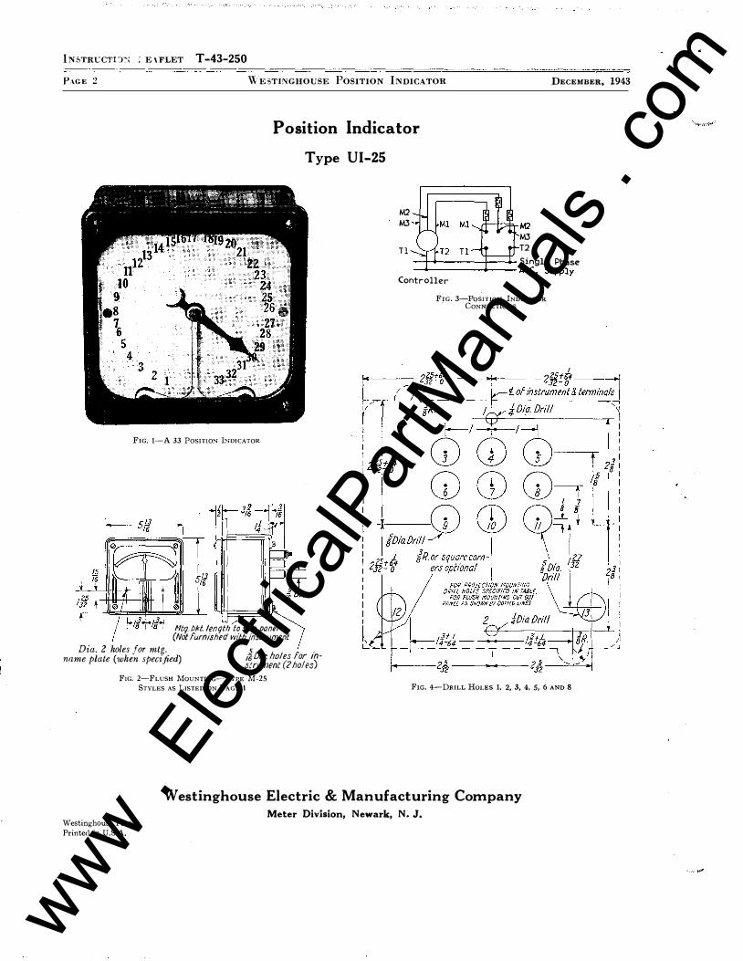
Position Indicator
Type UI-25
M2 M3
T l
DECEMBER, 1943
A--+--±._M2 M3 T2
--H>------1--+ Single Phase _._ ___ ___..1--- A-C . Supply
FIG, 1-A 33 POSITIO>I l>IDICATOR
Htq. bkl. /enqth to suit panel (Not furnished with instrument
Dia. 2 holes for mtg. name plate (when specified) /iDia: holes for instrument (2 holes)
FIG. 2-FLUSH MouNTING-TYPE M-25
STYLES AS LISTED ON PAGE 1
Controller
FIG. 3-PosniON INDICAToR . CONNECTIONS
FIG. 4-DRILL HoLES 1, 2, 3, 4, 5, 6 AND 8
Westinghouse Electric & Manufacturing Company Meter Division, Newark, N. J.
Westinghouse Press
Printed in U.S.A.
www . El
ectric
alPar
tMan
uals
. com

-
Supersedes I.L. 3235 Dated June, 1940 lNSTRVCTION LEAFLET T -43-250*
DECE'I'IBER, 1943 WEsTINGHousE PosiTION INDICATOR PAGE 1
120 Volt Styles
S!ii 1009966 - 9 po�itions S !ii 1009967 - 1 7 positions S !ii 1 1 56644 - 33 positions
GENERAL The Type UI-25 posttlon indicator
is used for the remote indication of the positions of mechanisms. The style numbers listed on this leaflet are principally" used for indicating the positions of the tap changer on transformer equipment and operate on the rotating iron principle, similar to that used in synchrono;ocopes. A 33 position indicator is illustrated in Fig. 1 . CONSTRUCTION AND OPERATION
The Type UI-25 instruments operate as duplicate position telemeter receivers. The operating instruments, both sending and receiving, are similar to miniature synchronous motors excited by alternating current. The sending units are geared or otherwise mechanically driven by the mechanisms, the positions of which are to be indicated at a remote point, in such a way as to turn the transmitter armature. The sending and receiving instruments are tied together electrically by several connecting wires in a manner similar to the connections between a synchronous motor and a generator. �With such connections, the rotor of the receiving instrument automatically remains in duplicate position to that of the transmitter. The name, "Synchrotie", is descriptive of the action.
* Supersedes I. L. 3235
Position Indicator
Type Ul-25
INSTRUCTIONS
T H E E Y E S I N D tsT R Y
The Type UI-25 receiver movement is enclosed in a square switchboard type instrument case designed to match other instruments of the H or 25 line types. The transmjtting unit is aE:tuated by the tap changer operating mechanism to which it is mechanically connected so that each tap changer position is definitely geared to the same angular position of the transmitter.
Note :
This instruction leaflet pertains only to the style numbers listed on this sheet and furnished for use with a complete transformer equipment. For general instructions on other styles of position indicator equipment refer to I. L. 43-?49, copies of which are obtainable from the Meter Division at Newark, N. ]. or through the district office.
INSTALLATION If the indicator is shipped as a sepa
rate item it should be unpacked carefully
240 Volt Styles
S!ii 1009968 - 9 positions S !if 1009969 - 1 7 positions S !ii 1 1 56645 - 33 positions
and mounted on the switchboard as usual for indicating instruments. The connections should be made as per Fig. 3 and as shown on the general wiring diagram supplied with the transformer apparatus. After installing the indicator it should be checked by operating the tap changer.
A half-revolution error in the indications of any receiving instrument is caused by the reversal of the leads to the single phase supply line. Reversed direction of operation is caused by incorrect sequence of the three wire system of rotor connections, M,, M,, M3• A "phase" error of 120 degrees indicates that the leads M,, M2, M3, are not connected to the corresponding terminals of the transmitter.
MAINTENANCE The indicator should not require any
field adjustments. Keep the indicator clean with cover tightly in place. Avoid excessive vibrations or shocks.
REPAI RS AND PARTS Major repairs can be most satis
factorily done at the factory or Westinghouse Service Shops: However, for customers equipped to do their own work, parts may be furnished on order. In ordering any part or requesting any other information, always give entire nameplate reading.
www . El
ectric
alPar
tMan
uals
. com
Westinghouse I . L . 43-250-F I N S T A L L A TI O N • OPE R A T I O N • M A I N TEN A N CE
I N S T R U C T I O N S --25 LINE-
SWITCHBOARD INSTRUMENTS SIX- I NCH CLASSIFICATION
G E N E R A L
C a s e s
The first letter i n type designates the form of
case used.
U = Rect. Proj. Base M't'd 5¥:.!" x 5¥:.!".
K = Rect. Flush, Flange M't'd ()lh" x {)i/2 '.
M = Rect. Flush, Base M't'd 5- 13/16" x 5-13/ 16".
Z = Permanent Magnet Moving Coil with Electromagnet.
M e c h a n i s m s
The second letter in type designates the principle
of operation.
A = Repulsion Moving Iron.
X = Permanent Magnet Moving Coil.
T = Thermocouple plus x.
C = Rectift'er plus x.
Y = Electrodynamic .
I = Rotating Iron Vane.
Insu l ation R ating
All Ammeters and Voltmeters are insulated for
750 volt maximum service. Wattmeters , power factor
meters , frequency meters and synchroscopes are in
sulated for 250 volt service.
D i a l N otes
References to type, style number, use of external
shunts, calibration data, etc . , are referred to on dial.
The full scale marking of an indicating instrument
is not necessarily the same as the ratings of the cur
rent and voltage coils. The coil ratings are based
upon temperature requirements. Full scale values are
chosen to give clear, simple scale markings of the
values of 1, 1 .2 , 1 .5, 2, 2.5 , 3 , 4, 5, 7.5, 8, or decimal
multiples of these values.
These coil ratings are given in the data lines near
the bottom of the dial plate, and are not necessarily
part of the calibration data of the instrument. The
calibration data are marked on the dial and in the case
of Wattmeters and Varmeters comprise the calibration
constant K and the ratios of the current and potential
SUPERSEDES I . L. 43-250-E
transformers when these are used.
The constant K is the product of the ratios of the
current and potential transformers. It is equal to the
number of Kilowatts (or Kilovars) indicated per Kilo
watt (or Kilovar) applied to the coils, on a single
phase test circuit.
I n sta l l ation
Unpack instrume nts carefully. Terminal and
mounting hardware, and any external resistors or re
actors may be in separate packages.
Drill panels and connect acccrding to the diagrams
in this leaflet, or according to switchboard drawings
if instruments are supplied as part of a switchboard.
On any instruments which operate with spring
control , such as ammeters , voltmeters or wattmeters,
adjust the pointer to zero by means of the zero ad
juster before energizing the windings. Power factor
meters, position indicators , synchroscopes and fre
quency meters do not have zero adjusters .
C I R C U I T P R E C A U T I O N S
The secondary circuits of all instrument trans
formers should be grounded.
The external connecting diagrams for the A-C in
struments show the proper locations for ground con
nections for the secondary circuits of the instrument
transformers, and for the instrument cases.
The ground connection of the cases should be
omitted when instruments are mounted on •uve front "
switchboard panels.
C A L I B R A T I O N
A-C. Instruments
T ypes A-25 ammeters and vo ltmeters operate on
the repulsion iron vaae principle . Calibration adjust·
ments are made by shifting the outer end of the spring
in its holder. After loosening the small clamping
screw, the zero adjuster should be left in mid-position,
the pointer being set to zero by shifting the small
EFFECTI VE AUGUST 1 959 www . El
ectric
alPar
tMan
uals
. com
25 LINE SWITCHBOARD INSTRUMENTS _____________________ _
tail piece of the inner spring adjuster located beneath
the spring , using a small suitable tool. The outer
spring clamping screw must be tightened before shift
ing the inner spring adjuster.
T y pe Y - 25 w a ttmeters are the electrodynamic
type. Polyphase wattmeters may be checked on single
phase circuits by testing each element separately, or
the current coils may be connected in series and the
potential coils in parallel, and both elements tested
at the same time. Calibration adjustments are made
by changing the resistance of the potential circuit.
V armeters are exactly like the wattmeters, except
that they indicate the reactive volt-amperes by means
of external phase shifting transformers. They are
often made with zero center scales. When used on
unidirectional circuits the scales are marked "lag"
and "lead" as in power factor meters. When intended
for tie lines or other duo-directional circuits, the lag
and lead notations are generally omitted and direc
tional markings are substituted, to show direction of
reactive power flow.
T ype Y-25 power fa ctor m eters are of the crossed
coil, electrodynamic type. Maximum accuracy is ob
tained when current in the current coils is from 40 to
125 per cent of coil rating and voltage on the potential
circuit from 75 to 125 per cent of normal. Polyphase
power factor meters are designed to indicate correctly
only on balanced load.
In order to test external 3 phase connections first
check in reference to phase sequence ( 1-2-3).
A trial connection may be checked by shunting
part of the current from the stationary coil with a low
resistance wire (about 0. 1 ohm) across the current
terminals. If the pointer movement is toward the lag
side of the scale, connections are correct. If the
pointer movement is toward the lead side of the scale
the connections to the first and third potential termi
nals should be interchanged on the line side of ex
ternal resistors if any are used.
Further incorrect actim� may be due to the current
connection being in the wrong phase, or re•1ersed,
giving six possible vector directions on three phase ,
one of which is correct for the power factor meter.
Should the pointer remain at one end of the scale
regardless of change in power factor the current con
nections should be interchanged. Polyphase power
factor met�rs are alijusted by changing the value of
resistance in the potential circuits. Single-phase
instruments are adjusted by changing the air gap of
z
the iron in the reactor or changing the value of re
sistance in the voltage circuit.
T ype Y-25 fre quency meters are of the crossed
coil electro dynamic type , the coils being connected
into a network consisting of a reactor and a capacitor
forming a resonant circuit.
If errors are found, the calibration may be cor
rected by adjusting the external reactor box. For this
purpose an iron screw is provided, accessible through
a hole in the perforated metal case. Changing the
internal resistor which shunts one of the moving coils
varies the over-all width of the scale range.
T y pe 1 - 25 sy nchra s co p e s operate on the rotating
iron vane principle. Calibration may be checked by
connecting both circuits to the same source. The
pointer should then indicate synchronism. If the
pointer does not indicate synchronism, it should be
shifted to the vertical position. If the rotation is
irregular, the currents in the reactcr branch a11d re
sistance branch should be equalized.
T ype 1· 25, 360-de gree scale power facto r m eters
are similar in mechanical construction to the synchro
scope. The inner coils are wound as current coils
and the outside stator coils wound as potential coils.
Connections may be checked the same as for type
Y-25 one-hundred degree scale power factor meters.
P erma nent M ag net Mov ing Co l i T y pe s
T ype X-25 voltm eter calibration adjustments are
made by changing the value of resistance in series
with the element. When used with an external resistor
on voltages higher than the insulation rating of the
instrument, one terminal of the instrument should be
kept at ground potential .
T ype X-25 ammeter calibration adjustments are
made by changing the resistance of the wire lead in
series with the element. When connected to an .<:lx
ternal shunt, leads listed for use with the instrument,
or leads of specified resistance should be used.
T yp e X-25 m i l l i ammeter calibration adjustments
are made by changing the resistance of the internal
shunt. Some ranges not provided with element shunts
are adjusted by changing the strength of the magnet.
T ype T-25 rad i o fre quency In strument calibration
adjustments are made by changing the value of the
resistance in series with the thermocouple. Tr. avoid
burning out the thermocouple, the instrument should
not be loaded above full scale.
www . El
ectric
alPar
tMan
uals
. com

25 LINE SWITCHBOARD I NSTRUME NTS ________________________________________ �I.L=·24�3·=2S=��F
Radio frequency instruments have the left termi
nal, as viewed from the rear, bonded to the metal
chassis and dial of the instrument. This prevents
electrostatic effects between pointer and dial and
provides points of zero potential inside the instrument.
Radio frequency instruments, particularly when
operated from external thermocouples , should be ar
rang ed with effective R.F. by-pass and ground con
nections to minimize the effect of capacity currents.
T y pe C-25 rectif ier type voltmeter calibration ad
justment s are mad'e by changing the value of series
re sistance . Rectifier type milliammeters ar e cali
brated by changing the strength of the magnet. Recti
fier type instruments indicate correctly at 25C. with
60 cycle pure sine wave.
T y pe Z - 25 D-C Wattmeter calibration may be
changed when required by varying the internal re
sistance which is in series with the moving element.
Under no condition must the external resistance in
series with the voltage coil be changed.
Use only the special leads furnished with the
instrument for connections to the ammeter shunt or
leads of resistance specified on the dial. No special
leads are required for the voltage circuit connections.
R E P A I R S A N D R E N E W A L P A R T S
Repair work can b e done most satisfactorily at the
factory. When returning an instrument for repairs,
obtain a returned material tag from your dealer or your
nearest Westinghouse Sales Office to assure proper
identification at the factory.
Orders for renewal parts should include the name
of the part and the style and serial number of the in
strument, appearing on the dial.
S pare L a m p s
Internally illuminated instruments use #46 Mazda
Lamps (6.3 volts 0 . 25 amp . ) We stinghouse style No.
1 ,00 1 ,663. These are rated at 3000 hour life at rated
voltage. 10 percent overvoltage greatly decreases life.
For 1 10 to 140 volt s , Type MT miniature trans
former, style #1246352 (6.3 volt secondary) is avail
able .
S pe c i a l Notes
For 3 element A-25 instruments, temperature indi
cators , or for special instruments, see separate
leaflets.
EXTERNAL CONNECTION DIAGRAMS (REAR VI EW)
FIG. 1 -AMMETER AND M ILLIAMMETER, SELF
CONTA INED
��
FIG. 6-AMMETER SEI F-CoNTAINED
Direct Current, Radio Frequency Instruments and lighting Circu i t
FIG. 2-AMMETRR WITH ExTERNAL SHUNT
Res, Used Only Above 800 Volts
FIG. 3-VoLTMHTER
Q To ' Voll Source
FIG. 4-FoR ALL INSTRuMENTS \\'ll H ILLUMINATION
Alternating Current Instruments
PIG. 7- AMMETER WITH CuRRENT TRANSI"ORMRRS
One Phase of Clrcutt
•• To one phase "':. of meter
P. T. as in diagrams.
Connechons lor A-C. Voltage Circuits ln Voltmeters, Wattmeters, Freq. Meters or Power Factor Meter1 when P. T. are not required.
PtG. ·- VOLTMRTRR
External
J
Ther:::::::d or
;Not Growtded
"1 Depending --�Upon Installation Instrument
FIG. 5-RF AMMETER ExTERNAL THERMOCOUPLE
External Resistor used only above 800 Volts
�I@ FIG. 9-VOLTMET&a
WITH POTENTIAL TaANtiFORMERS
3 www . El
ectric
alPar
tMan
uals
. com

25 L I N E SWITCH BOARD I NSTRUMENTS _____________________ _
4
ALTERNATING CURRENT INSTRUMENTS - Continued REAR VIEW
Fig. 10-Type 125 Single Phase Synchroscope
Fig. 13-Type Y25 Single Phase Power Factor Meter
mEXT. RES. U S £ D O N L Y
-
• • � • � v.
Fig. 16-Wattmeter, Single Phase
Fig. 19-Wattmeter. 2-Phase, 4-Wire ·
REAR V I EW
Fig. 11 -Type 125 Single Phase Power Factor Meter
3 2 1 100• SCAlE METERS SElF Coton. UP To 300 VOL"TS Sv-r Us£ RE:.51 STOR.S IN LINES 11 t AND 3 fOR M l<iHER. VOLTAGiES
Fig. 14-Type Y25 Power Factor Meter,
3-Phase, 3-Wire
E XT. R E�. USED ONL'i ABotJr:. �OOV.
Fig. 17-Wattmeter, 3-Phase, 3-Wire
Fig. 20-Varmeter, 3-Phase, 3-Wire
Varmeters will deflect to the right !or lagging
var now.
+
3 2 I PHASE ROTATION 1-2-3
Fig. 12-Type !25 Polyphase Power Factor Meter
X Z5 1 NST.
�� o �
P. T.
Fig. 1 5-Transducer Type Frequency Meter
EXT. RES. V!:>EO ONL.'/ A SoiJE 3ooV'.
Fig. 18-Wattmeter, 3-Phase, 4-Wire
0 3 2 I PHASE S. H I FT .... 4 C{ T R A "'l 'S F O ie. N\ e: e.
/
Varmeters will de!lect to the right for lagging var now.
Fig. 21-Varmeter, 3-Phase, 4-Wire
Fig. 22-Varmeter, Single Phase, 2 Wire
Fig. 23-Type Z-25 DC W•lttmet:Jr
www . El
ectric
alPar
tMan
uals
. com

25 LINE SWITCHBOARD INSTRUMENTS _________________________________________ I_. L_. _��_2_s� __ F
BV REMOVING THIS SCREW, CASE ASSEM LV MAY BE REMOVED T EXPOSE RESISTOR ELEMENTS.
AN ADOITION�1 L 7 INCHES OF SPACE IS REQUIRED IF CASE ASS tABLY IS TO BE REMOVAB E .
TERMINAL SCREWS 10 • 32 BINDING H EAO. FURNISHED WITH RE· SISTOR. SCREWS ARE SELF· LOCKING.
2 MOUNTING HOLES 13/64 OIA c' BR 11/32 OIA 1/2 DEEP.
tFOR NO. IO FIL HEAD SCREW). SCREWS NOT FURNISHE D .
s T .. :!: ,., ,.,
Fig. 24 Outline and Drilling Plan for Type VR-825 External Resistor
.2.01 0\f\ MTCi HOLi.S 2. HOLES T
Fig. 26 Outline and Drilling Plan for Phase Shifting Transformer used with 3-Phase, 3-Wire Varmeter
_/40UOo.loioLI!. 4-U-�
::. .... l!�'f- - - - - - ""'ltf' J I � I
7f I <>1- � I
j I I c I
"' I � \ I l +2f--z.i-�. I
T ! I fl.- - - - - - - --':! •'!:: - - � -� t----'IZ
't -,...---- 1
<7� --�-
r 0 0 @ @ E::3 �
l
Fig. 25 Outlim> and Drilling Plan for Transducer used with Frequency Meter
Fig. 27 Outline and Drilling Plan for Phase Shifting Transformer used with 3-Phase, 4-Wire Varmeter
_ _ _ _ _ _ _ jj
� .! I� 00000 llJ -1t} ��:gggo o
! !! ...... t i' ····�:·:: . !
Fig. 28 Outline and Drilling Plan for Reactive Compensator used with Single Phase Varmeter.
5 www . El
ectric
alPar
tMan
uals
. com
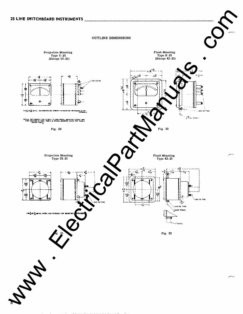
25 LINE SWITCHBOARD INSTRUMENTS ____________________________________________ _
6
f
Projection Mounting Type U-25
(Except UI-25)
Ir_._ .. __ + __ • .;J I"Oitt ORi M£TAI.. SWITCH80AiltO,USE SCIWWI I'"Oft NOUNTIN6 INSTitUME�:.:::.s
Fig. 29
Projection Mounting Type UI-25
Fig 31
OUTLINE DIMENSIONS
190-32THO.
Flush Mounting Type K-25
(Except Kl-25)
Fig. 30
Flush Mounting Type Kl-25
L ' � �""' . 190-32 THD.
�'"'" I I l.. __ �I"PANEL
Fig. 32
. 190-32 THO.
www . El
ectric
alPar
tMan
uals
. com

25 L i m : : SWITCH BOARD INSTRUMENTS ____________________ ...:..:l ·c::L:..... 4.:..::3--=2;:,..:5!1-:....:....F
FRONT VIEW
1. A. C. or D. C. Ammeter, Voltmeter Clocks 2. Freq. Meter Self Contained Ground Detectors
and Differential Voltmeter 3. For Single Phase Wattmeter & D. C. Wattmeter 4. For P. F. Meter & Self. Cont. Temp. lndicator 5. For Polyphase Wattmeter 3 Pot. Terms. 6. For Polyphase Wattmeter 4 Pot. Terms. 7 . For 3 C. C. Wattmeter. 8. For Dial Illumination Lamp Terms. 9 . For Total Hour Meter
1 0. For 125 Synchroscope or Power Factor
Fig. 33
DRILLING PLAN
Drill Holes 1-2-6-8
1-2-6-7-8 1-2-3- 5-6-8 1 -2-3-4-5-6-8 1-2-3-4-5-6-8-9-11 1-2-3-4- 5-6-7 -8- 9 - 1 1 1-2- 3-4-5-6-7-8 -9 -10-11 12-13 1-2-6-8 Per Fig. 34
Fig. 34
7 www . El
ectric
alPar
tMan
uals
. com

W E S T I N G H O U S E E L E C T R I C C O R P O R A T I O N I NSTR U M E N T D E PA RT M E N T N EWA R K, N. J.
Printerl i n U . S . A . www . El
ectric
alPar
tMan
uals
. com