Embed Size (px)
Citation preview

Signa
l Tow
ers

Tech-
Talk
11
Completely pre-assembled Signal Towers
For KombiSIGN 70 + 71Page 43 + 24
For KombiSIGN 70 + 71Page 44 + 23
For KombiSIGN 70 + 71Page 45 + 26
Wireless-based Signal Tower Solutions
SoundThe sounds can be played from our website
www.werma.com under the heading „Signal Towers“.
Further InformationFurther informationen about “Light in signalling technology”
can be found in the chapter “Tech-Talk” beginning on page 320.
IP 65 • Ø 70 mmPage 16
KombiSIGN 71
IP 54 • Ø 70 mmPage 36
KombiSIGN 70
IP 54 • Ø 50 mmPage 54
KombiSIGN 50
IP 65 •With curved front
Page 68
FlatSIGN
IP 65 • Customer-specific Design
Page 71
FlatSIGNDesign Highlights
IP 65 • Ø 42 mmPage 66
deSIGN 42
IP 67/IP 69k •Hygienic Design
Page 76
CleanSIGN
IP 65 •Innovative Design
Page 72
VarioSIGN
IP 65 • Ø 36 mmPage 63
KOMPAKT 36
IP 65 • Ø 70 mmPage 64
KOMPAKT 71
www.werma.comSoundP lay
Modular Signal Towers
WIN – Wireless Information
Network
KombiSIGNreflect
GSM TransmitterElement
www.werma.com
Signa
l Tow
ers
Overview Signal Towers
NEW
NEW NEW
NEW NEW

12
Modular Signal Towers
www.werma.com
Signal Towers OverviewSigna
l Tow
ers
Ove
rview
Ø 70 mm Ø 50 mm
• Protection rating IP 65
• For use in extreme conditions
Page 16 onwards.
• Protection rating IP 54
• For use in normal conditions
Page 36 onwards.
• Protection rating IP 54
• For use in normal conditions
Page 54 onwards.
• WIN – WirelessInformation Network
• KombiSIGN reflect
• GSM Transmitter Element
Page 23 onwards.
KombiSIGN 71 KombiSIGN 70 KombiSIGN 50 Wireless-basedsolutionsfor KombiSIGN 70 + 71
NEW
Ø 70 mm
WIN – Wireless Information Network
KombiSIGN reflect
GSM Transmitter Element
• Modular system allows a completely free combination of optical andaudible signal elements.
• Mechanical and electrical connection of the elements in the space ofseconds using a bayonet connection system.
• Completely safe element changes (contact-voltage proof) without the need for tools.
Page 16 onwards.
The Signal Devices Site on the internet:With our ”Configurator“ you can put together a signal tower quickly and easily according to your requirements. The configurator interactively guides the user through a series of pictures and questions to create an individualsignal tower solution in just a few clicks.
TIP

13
Completely pre-assembled Signal Towers
www.werma.com
deSIGN 42
Signa
l Tow
ers
Ove
rview
Ø 42 mm
• Protection rating IP 65
• 2 or 3 tier
• High-quality stain-less steel housing
Page 66 onwards.
KOMPAKT 36KOMPAKT 71
Ø 36 mm / Ø 70 mm
• Protection rating IP 65
• 2 or 3 tier
• Available in 2 sizes
Page 63 + 64.
CleanSIGN
112 x 485 x125 mm
• Protection rating IP 67/69k
• For use in the foodand pharmaceuticalindustry as well
as in cleanroomapplications
Page 76 onwards.
FlatSIGN
195 x 105 x 45 mm
• Protection rating IP 65
• With curved front
• 160°signal visability
Page 68 onwards.
VarioSIGN
62 x 220 x 90 mm
• Protection rating IP 65
• Electronic modularity
• Unique design
Page 72 onwards.
• Completely pre-assembled LED signal towers.• The complete tower can be ordered using a single number, considerably simplifying the ordering process.
• LED technology with a life duration of up to 50,000 hours. The replacementof elements or light bulbs is therefore no longer necessary.
From Page 63 onwards.
NEW NEW

70 mm70 mm
14
50 mm
www.werma.com
Signals to combine – At the twist of a hand
Signal elements in every common voltage
Modular system allows combination as required
High protection rating IP 54 or IP 65
Wide range of optical and audible elements
LED technology ensures even better visibility
New attention-grabbing light effects (e.g. EVS)
KombiSIGN 71 KombiSIGN 70 KombiSIGN 50
Signal Towers KombiSIGN Signa
l Tow
ers ●
modular
Kom
biS
IGN
Protection Rating IP 65
Modular signal tower system with 70 mmdiameter for use in in extreme conditions.
Not compatible with KombiSIGN 70
Terminal Element
Either: improvedscrew terminal
Or: terminal element withCAGE CLAMP® technology
Cylindrical terminal element
See page 16.
Protection Rating IP 54
Modular signal tower system with 70 mmdiameter for use in in normal conditions.
Not compatible with KombiSIGN 71
Terminal Element
Screw terminal
Conical terminal element
See page 36.
Protection Rating IP 54
Modular signal tower system with 50 mmdiameter for use on smaller machines.
Terminal Element
Screw terminal
Practical bayonetfixing systemtool-free bulb-change.
See page 54.

15
1 2 3
www.werma.com
Terminal elements with CAGE CLAMP® technology enable leads to be quickly and easily wired, guaranteeing a secure and reliable contact.
Safe and efficient connectionthanks to CAGE CLAMP® technology
Indication board for the addition of instructions
KombiSIGN Signal Tower with Foldaway Base
WERMA was the first signal beacon manufacturer to offer a bayonet mechanism allowing elements to be mechanically and electrically connected within seconds.
Simple mounting and removal of the elements
New combinations at the twist of a hand
Tool-free bulb change
The comprehensive range of accessories for KombiSIGNsignal towers offers solutions for the most diverse moun-ting needs and exceeds the industry standards in this respect.
Besides the wide choice of brackets, bases and tubesWERMA also offers unique special solutions, for examplethe Foldaway Base, the Tube with Clamp or the IndicationBoard.
You will find an overview of the entire range of accessories for KombiSIGN Signal Towers on pages 60 and 61.
A fitting solution for every mounting requirement
Simple operation thanks to bayonet mechanism
Signa
l Tow
ers ●
modular
Kom
biS
IGN
Insert screwdriver at a slightangle into opening as faras possible.
Open spring-loaded clamp withthe help of the screwdriver andinsert wire as far as possible
Remove screwdriver –the wire is firmlyclamped.
CAGE CLAMP® is a registered trademark of WAGO Kontakttechnik GmbH.
Fault
Refill
Overheating
Station 2
Machine inoperation

16
Contact box for cable exit at sideOrder no. 975 840 01
Tube with clampOrder no.960 000 18
Adaptor forsingle holemountingOrder no.960 000 25
Base with integratedtubeOrder no.975 840 10
Tube Ø 25 mm, all anodized Order no.100 mm long 975 845 10250 mm long 975 840 25400 mm long 975 840 40600 mm long 975 840 60800 mm long 975 840 801000 mm long 975 840 03
Base for Tube, plasticOrder no. 975 840 90
Base for Tube, metalOrder no. 975 840 91
Foldaway BaseOrder no. 960 000 30
Tube Ø 25 mm, plastic, only forFoldaway Base, 45 mm longOrder no. 960 000 31
Bracket for base mountingOrder no. 960 000 02
Contact box for cable exit at sideOrder no. 975 840 01
Contact box with magnetic base and cable exit at sideOrder no. 975 840 04
Bracket for 1-sided mountingOrder no. 975 840 85
Bracket for 2-sided mountingOrder no. 975 840 86
Bracket for base mountingwith concealed cable entryOrder no. 960 000 14
Bracket for tube mountingOrder no. 960 000 01
This is how you can assemble your KombiSIGN 71 signal tower!
STEP 1Select the required optical or audible elements.
Many KombiSIGN highlights are also available (for detailssee page 17).
Audible Signal Elements• Buzzer Element• Siren Element• Vocal Element
Optical Signal Elements• (LED) Permanent Light• LED Permanent Light ultrabright• (LED) Flashing Light• LED EVS Element• LED Blinking Light• LED Rotating Light
Improved screwterminalOrder no. 640 820 00
Terminal element with CAGE CLAMP® technologyOrder no. 640 800 00
Improved screwterminalOrder no. 640 830 00
Terminal element with CAGE CLAMP® technologyOrder no. 640 810 00
Base Mounting Tube Mounting
www.werma.com
Signal Tower KombiSIGN 71Signa
l Tow
ers ●
modular
Kom
biS
IGN
71
STEP 4Where appropriate, select a baseand the desired tube length (only for tube mounting).
STEP 5Where appropriate, select thebracket and the contact box.
The Signal Devices Site on the Internet:www.werma.com
With our new signal tower configuratoryou can put together your own indi-vidual signal tower.
TIP
STEP 2Select the appropriate mountingoption for your application.
STEP 3Select the correct terminal element for your mounting option.
NEW

17
The Highlights for KombiSIGN 71
NEW
NEW
NEW
This Signal Tower speaks to you!
WIN – Wireless InformationNetwork
• Economical wireless-based Machine Data Collection system (MDC system)
• Central monitoring of a wide range of different machines via PC
See page 24
KombiSIGNreflect
• Simple monitoring of signal towers out of view
• Signal tower ”reflection“ to a central location
See page 23
LED Permanent LightElement ultrabright
• Up to 20 times brighter than conventional LED elements
• Maximum brightness via intelligent LED control
See page 28
LED EVS Element
• Attention-grabbing flickering light
• Extremely powerful signal effect
• Random sequence of light signals prevents acclimatisationeffect
See page 29
Foldaway base
• Enables signal towers to be folded down completely, even when connected
• Vertical alignment of signal towers even on sloping surfaces
See page 35
Vocal Element
• Plays customer-specific audio files in mp3 format (sounds, alarms, music or spoken text)
• Easy programming via USB interface
• Up to 60 minutes replay capacity
See page 30
GSM Transmitter Element
• Malfunction signalled by signal tower is transmitted via SMSor call to a mobile phone
• Activation without the need for programming
• No additional power supply needed
See page 26
LED Flashing Light Element
• Extremely long life duration up to 50,000 hrs
• Low current consumption• Shock-proof and vibration resistant
See page 18
AS-Interface Element
Customer-specificcoloured coatings
Siren Element with self-adjusting sound output
Terminal Element with USB Interface
• LEDs indicate current status• 31 or 62 addresses• Available with standard or A/B technology
See page 27
• Signal towers in customer-specific colours – complete range of RAL colours available
• Meets the demands of an increasing design orientation
See page 33
• Sound output is automatically adjusted to the backgroundnoise level
• Warning tone can be heard without being irritatingly loud
See page 31
• Direct triggering of signal tower elements via USB Interface
• Easy activation
See page 32
www.werma.com
Signa
l Tow
ers ●
modular
Kom
biS
IGN
71

IP65
+50°C
-20°C
105 dB2
Ws
18
PLC
24 V
www.werma.com
Improved
light effect
Bracket (accessory)
Base with tube (accessory)
640 Signal Tower KombiSIGN 71
• High protection rating IP 65• Signal tower system 70 mm Ø with modular construction
• Improved illumination• Flexible combination of optical and audible elements
Dimensions (Ø x Height): Terminal element: 70 mm x 26.5 mm Light element: 70 mm x 65 mm Audible element: 70 mm x 72/79/111 mmHousing: Terminal element: PA fibreglass, high-impact Cap: PCLens: PC, transparent Audible and ASI elements: PCFixing: Base mounting Tube mounting, for tube Ø 25 mm Bracket mounting (accessory)Socket: Bayonet, B15d, for bulbs max. 7 WConnection: CAGE CLAMP® technology max. 2.5 mm2
or screw terminal max. 2.5 mm2
Contact protection according to VDECable entry: Cable diameter max. 14 mmElement seal: Pre-mounted with each moduleProtection rating: Light elements: IP 65 Audible elements: IP 65 (Order no. 645 830 55 = IP 40)Number of modules possible: Max. 5 /max. 10 elements with 2-sided bracket
Permanent light element 12 - 240 V Bulb not included in assembly.
LED Permanent light element 24 V 115 V 230 VCurrent consumption: < 30 mA < 20 mA < 20 mA
LED Permanent light element ultrabright 24 VLife duration: Up to 50,000 hrsCurrent consumption: Max. 190 mAUp to 20 times brighter than conventional LED beacons.
Flashing light element (Xenon) 24 V 115 V 230 VLife duration: 4 x 10⁶ flashesCurrent consumption: 125 mA 22 mA 15 mAReduced for AS-Interface: 80 mAFlash frequency: c. 1 Hz
LED Flashing light element 24 VLife duration: 50,000 hrsCurrent consumption: < 30 mA (red/yellow) < 25 mA (green/clear/blue)Flash frequency: c. 1 Hz (Double Flash)
LED EVS* element 24 VCurrent consumption: 350 mA (red/yellow) 250 mA (green/clear/blue)* EVS = Enhanced Visibility System
LED Blinking light element 24 V 115 V 230 VCurrent consumption: 25 mA 25 mA 25 mABlink frequency: c. 1 Hz
LED Rotating light element 24 VCurrent consumption: 70 mA Rotation frequency: c. 120 r.p.m.
Signa
l Tow
ers ●
modular
Kom
biS
IGN
71
NEWNEW
TECHNICAL SPECIFICATIONS:

19www.werma.com
Life duratio
n
up to 50,00
0 hrs
Improved
light effect
Permanent light element 12-240 V red 641 100 00 green 641 200 00 yellow 641 300 00 clear 641 400 00 blue 641 500 00Bulb not included in assembly. Accessories see page 22.
LED Permanent light element 24 V 115 V 230 Vred 644 100 75 644 100 67 644 100 68green 644 200 75 644 200 67 644 200 68yellow 644 300 75 644 300 67 644 300 68clear 644 400 75 644 400 67 644 400 68blue 644 500 75 644 500 67 644 500 68
LED Permanent light element ultrabright 24 V red 644 180 55 green 644 280 55 yellow 644 380 55 clear 644 480 55 blue 644 580 55 Flashing light (Xenon) 24 V (ASI) 24 V 115 V 230 Vred 643 110 55 643 100 55 643 100 67 643 100 68green 643 210 55 643 200 55 643 200 67 643 200 68yellow 643 310 55 643 300 55 643 300 67 643 300 68clear 643 410 55 643 400 55 643 400 67 643 400 68blue 643 510 55 643 500 55 643 500 67 643 500 68
LED Flashing light element 24 V red 644 120 55 green 644 220 55 yellow 644 320 55clear 644 420 55blue 644 520 55
LED EVS element 24 V red 644 140 55 green 644 240 55 yellow 644 340 55 clear 644 440 55 blue 644 540 55
LED Blinking light element 24 V 115 V 230 Vred 644 110 75 644 110 67 644 110 68green 644 210 75 644 210 67 644 210 68yellow 644 310 75 644 310 67 644 310 68clear 644 410 75 644 410 67 644 410 68blue 644 510 75 644 510 67 644 510 68
LED Rotating light element 24 V red 644 130 75 green 644 230 75 yellow 644 330 75clear 644 430 75blue 644 530 75
Further voltages on request.
(LED) Permanent/Flashing element
LED EVS element
Permanent light, clear with info
LED element
Compare the pri
ces
and advant
ages of
an LED Flash
ing light
Signa
l Tow
ers ●
modular
Kom
biS
IGN
71
NEW
TECHNICAL DIAGRAMS: see page 277 onwards
ORDER SPECIFICATIONS OPTICAL ELEMENTS:

20
NEW
NEW
NEW
NEW
www.werma.com
Terminal element for tube mounting CAGE CLAMP® Screw terminalincluding cap 640 810 00 640 830 00
Terminal element for bracket or base mounting including cap and seal 640 800 00 640 820 00
Terminal element with USB Interface (for tube mounting) 640 840 00 Technical specifications see page 32.
Terminal element with cap
Audible element
Siren element withself-adjusting sound output
Vocal element
GSM transmitter element
Buzzer element 24 V 115 V 230 V85 dB, 25 mA, IP 65, 645 800 75 645 800 77 645 800 68Continuous or pulse tone
Siren element 24 V105 dB, 150 mA, IP 40 645 830 55Continuous tone alternating no UL approval
Multi-functional Siren 24 V / 80 mA 115 V / 40 mA 230 V / 40 mA100 dB, IP 65, 8 different 645 820 75 645 820 67 645 820 68tones, adjustable sound output
Multi-functional Siren, 24 Vcan be triggered externally 645 850 55100 dB, 80 mA, IP 65, 7 diff. tones can be triggered externally, adjustable sound output,number of tones depending on the number of optical elements.
Siren element with 24 Vself-adjusting sound output 645 810 55Technical specifications see page 31.
WIN system for KombiSIGN 71 860 640 01Technical specifications see page 24.
WIN complete for KombiSIGN 71 860 640 03Technical specifications see page 24.
WIN slave for KombiSIGN 71 860 640 02Technical specifications see page 24.
KombiSIGN 71 reflect 861 640 01Technical specifications see page 23.
GSM Transmitter Element 24 Vfor KombiSIGN 71 646 700 55Technical specifications see page 26.
Vocal Element 24 Vfor KombiSIGN 71 645 840 55Technical specifications see page 30.
AS-Interface Element Standard Slave A/B-Slavefor KombiSIGN 71 24 V 24 V 646 830 55 646 810 55Technical specifications see page 27.
640 Signal Tower KombiSIGN 71
Signa
l Tow
ers ●
modular
Kom
biS
IGN
71 ORDER SPECIFICATIONS AUDIBLE ELEMENTS:
ORDER SPECIFICATIONS TERMINAL ELEMENTS :
ORDER SPECIFICATIONS KOMBISIGN-HIGHLIGHTS:
21www.werma.com
TECHNICAL DIAGRAMS: see page 292 onwards
Accessories for Signal Tower KombiSIGN 71
Signa
l Tow
ers ●
modular
Kom
biS
IGN
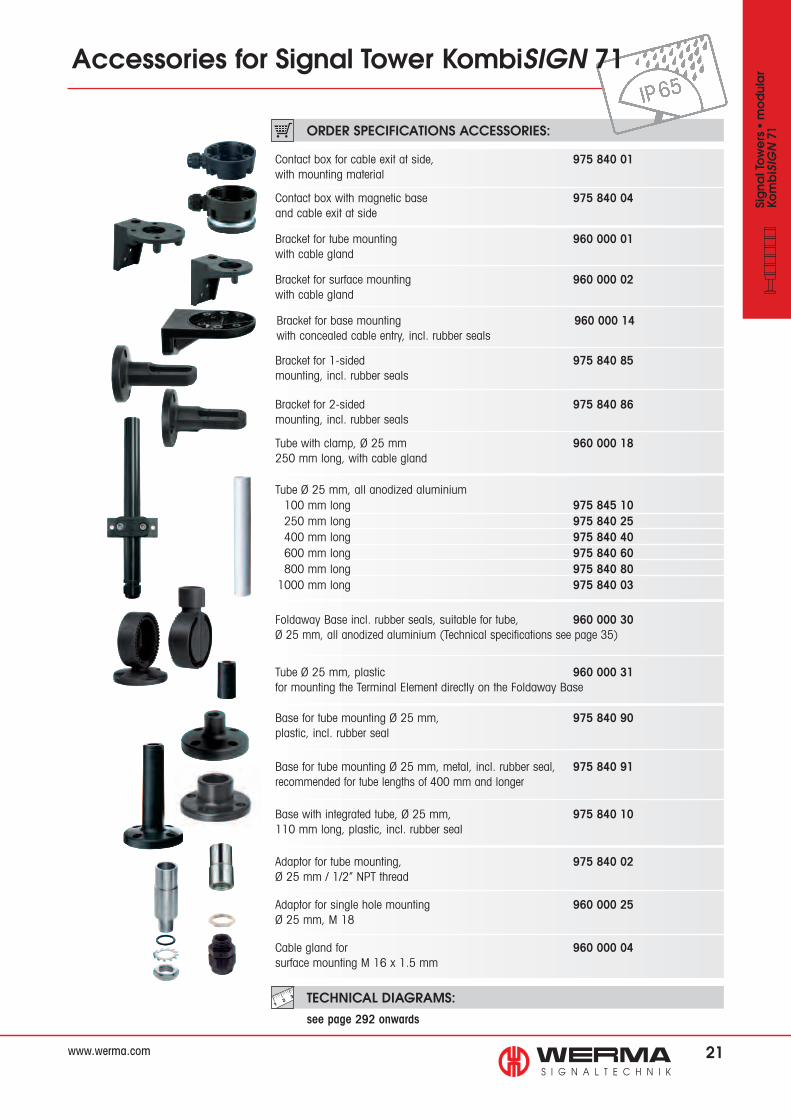
71 ORDER SPECIFICATIONS ACCESSORIES:
Contact box for cable exit at side, 975 840 01with mounting material
Contact box with magnetic base 975 840 04and cable exit at side
Bracket for tube mounting 960 000 01with cable gland
Bracket for surface mounting 960 000 02with cable gland
Base for tube mounting Ø 25 mm, 975 840 90plastic, incl. rubber seal
Tube Ø 25 mm, plastic 960 000 31for mounting the Terminal Element directly on the Foldaway Base
Foldaway Base incl. rubber seals, suitable for tube, 960 000 30Ø 25 mm, all anodized aluminium (Technical specifications see page 35)
Bracket for 1-sided 975 840 85mounting, incl. rubber seals
Bracket for 2-sided 975 840 86mounting, incl. rubber seals
Tube with clamp, Ø 25 mm 960 000 18250 mm long, with cable gland
Base for tube mounting Ø 25 mm, metal, incl. rubber seal, 975 840 91recommended for tube lengths of 400 mm and longer
Base with integrated tube, Ø 25 mm, 975 840 10110 mm long, plastic, incl. rubber seal
Adaptor for tube mounting, 975 840 02Ø 25 mm / 1/2” NPT thread
Adaptor for single hole mounting 960 000 25Ø 25 mm, M 18
Cable gland for 960 000 04surface mounting M 16 x 1.5 mm
Bracket for base mounting 960 000 14with concealed cable entry, incl. rubber seals
Tube Ø 25 mm, all anodized aluminium 100 mm long 975 845 10 250 mm long 975 840 25 400 mm long 975 840 40 600 mm long 975 840 60 800 mm long 975 840 801000 mm long 975 840 03

22 www.werma.com
number „6” 975 840 56number „7” 975 840 57number „8” 975 840 58number „9” 975 840 59number „10” 975 840 92arrow 975 840 62
Signa
l Tow
ers ●
modular
Kom
biS
IGN
71
Accessories for Signal Tower KombiSIGN 71
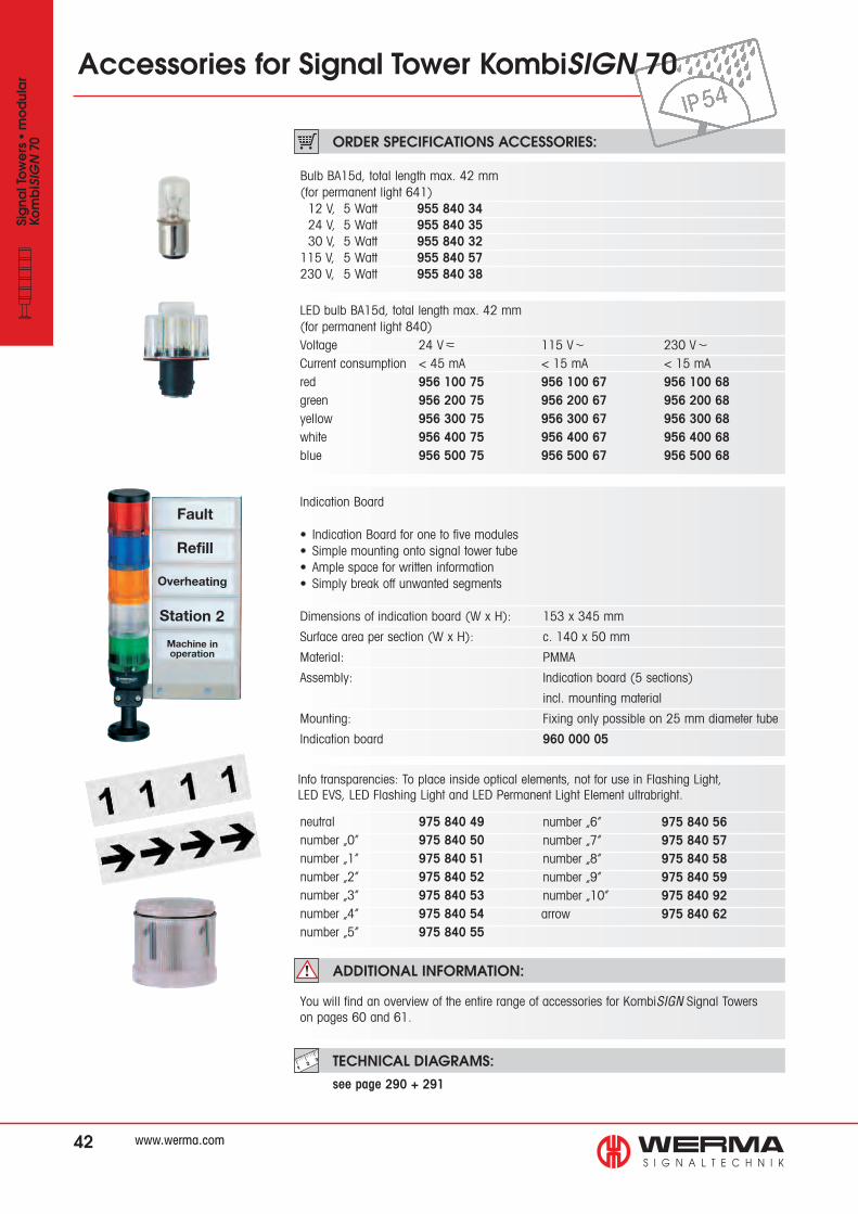
Bulb BA15d, total length max. 42 mm(for permanent light 641)12 V, 5 Watt 955 840 3424 V, 5 Watt 955 840 3530 V, 5 Watt 955 840 32115 V, 5 Watt 955 840 57230 V, 5 Watt 955 840 38
LED bulb BA15d, total length max. 42 mm(for permanent light 641) Voltage 24 V 115 V 230 VCurrent consumption < 45 mA < 15 mA < 15 mAred 956 100 75 956 100 67 956 100 68green 956 200 75 956 200 67 956 200 68yellow 956 300 75 956 300 67 956 300 68white 956 400 75 956 400 67 956 400 68blue 956 500 75 956 500 67 956 500 68
Indication Board
• Indication Board for one to five modules• Simple mounting onto signal tower tube• Ample space for written information• Simply break off unwanted segments
Dimensions of indication board (W x H): 153 x 345 mm
Surface area per section (W x H): c. 140 x 50 mm
Material: PMMA
Assembly: Indication board (5 sections)
incl. mounting material
Mounting: Fixing only possible on 25 mm diameter tube
Indication board 960 000 05
Info transparencies: To place inside optical elements, not for use in Flashing Light, LED EVS, LED Flashing Light and LED Permanent Light Element ultrabright.
neutral 975 840 49number „0” 975 840 50number „1” 975 840 51number „2” 975 840 52number „3” 975 840 53number „4” 975 840 54number „5” 975 840 55
You will find an overview of the entire range of accessories for KombiSIGN Signal Towerson pages 60 and 61.
ADDITIONAL INFORMATION:
ORDER SPECIFICATIONS ACCESSORIES:
TECHNICAL DIAGRAMS: see page 292 onwards
Fault
Refill
Overheating
Station 2
Machine inoperation

23
+50°C
-20°CIP65 PLC
TECHNICAL DIAGRAMS: see page 289
Simple monitoring of signal towers out of view
Simply fit the KombiSIGN reflect slave to the signal tower on the
machine
ADDITIONAL INFORMATION:
NEW
www.werma.com
Signa
l Tow
ers ●
modular
Kom
biS
IGN
71
861 KombiSIGN reflect for KombiSIGN 71
• KombiSIGN reflect is integrated into existing WERMA signal towers• No additional wiring costs • Simple commissioning due to pre-configured modules
ORDER SPECIFICATIONS:
TECHNICAL SPECIFICATIONS:
KombiSIGN 71 reflect 861 640 01
SlaveDimensions (Ø x Height): 70 mm x 65.5 mmHousing: PC, blackConnection: BayonetOperating voltage: 24 VCurrent consumption: 40 mA
MasterDimensions (Ø x Height): 70 mm x 65.5 mm (without antenna)Housing: PC, blackConnection: BayonetOperating voltage: 24 VCurrent consumption: 40-90 mA
Wireless connectionISM frequency: 868 MHz (KombiSIGN reflect conforms to the EU’s EN 300220 harmonised standard and can thus be used in all EU member countries. Further countries upon request.) Transmission range: Up to 300 m (unobstructed line of sight)
• Simple monitoring of signal towers out of view• Signal tower “reflection” to a central location• Shortening of reaction times and reduction of costs
The slave sends the status directlyto the master, and reflects the
status of the signal tower installedon the machine
Remote transmission via wireless signal with a maximum range of up to
300 m (unobstructed line of sight)
Signal tower “reflection”WERMA Signaltechnik provides a simple solution for the remote wireless monitoring of machinery. The new “KombiSIGN reflect” kit can be integrated into existing signal towerswhich are already installed on your machines. KombiSIGN reflect “reflects“ the status of the machine to a signal tower within your line of sight.
This enables you to wirelessly monitor machines situated at a greater distance and respond quickly to malfunctions. With KombiSIGN reflect, even machines which where not previously network-capable can now be remotely monitored.
Further informationen can be found in the chapter ”Tech-Talk“ on page 324.

24
TECHNICAL SPECIFICATIONS:
WIN slaveDimensions (Ø x Height): 70 mm x 65.5 mmHousing: PC, blackConnection: BayonetOperating voltage: 24 VCurrent consumption: 40 mA
WIN masterDimensions (L x H x W): 76 mm x 30 mm x 80 mm (without antenna)Housing: ABS, blackConnection: Via USBOperating voltage: Via USBCurrent consumption: < 100 mASuitable for: Windows 2000, Windows XP, Windows Vista, Windows 7
Wireless connectionISM frequency: 868 MHz (WIN conforms to the EU’s EN 300220 harmonised standard and can thus be used in all EU member countries. Further countries upon request.) Transmission range: Up to 300 m (unobstructed line of sight) Every slave simultaneously functions as a “repeater”, enabling the transmission range to be significantly increased.
WIN completeWith the all inclusive kit “WIN complete” you can immediately start monitoring up to threemachines. All you have to do is mount the signal towers from the kit onto your machines.After installing the supplied software on to your PC you can immediately start monitoring thestatus of your machines.
Assembly: WIN master, 3 WIN slaves for KombiSIGN 71 (pre-configured), 3 KombiSIGN 71 signal towers (LED permanent light elements in red, yellow and green, terminal element, base with integrated tube), software
WIN systemWith “WIN system” the user has even more choice: The kit consists of a WIN masterincluding the software, a USB cable and three pre-configured WIN slaves.The slaves are fitted to the existing WERMA signal towers which need to be monitored.Or you can order your own signal towers from WERMA’s wide range of KombiSIGNproducts - enabling you to combine audible elements, different light effects, colours andmounting options as required.
Assembly: WIN master, 3 WIN slaves for KombiSIGN 71 (pre-configured), Software
Patent pen
ding
Signa
l Tow
ers ●
modular
Kom
biS
IGN
71
• Economical wireless-based Machine Data Collection system (MDC system)• Central monitoring of a wide range of different machines via PC• Relevant machine information at a glance
• Reduction of reaction times, repair and maintenance require- ments and costs• No additional wiring as existing WERMA signal towers can be used• Downtime analysis
The all inclusive kit for KombiSIGN 71: “WIN complete” consists of three pre-
configured signal towers and the master
Expandable at any time: With additional“WIN slaves” up to 50 machines can be
integrated into the network
“WIN system” is immediately readyfor use: Fit the slaves in the existing
signal towers and connect themaster to the PC
NEW
860 WIN* for KombiSIGN 71
www.werma.com

25
+50°C
-20°CIP65 SPS
Module 1: Status indication of the networked signal towers
Examples:
Module 2: Productivity per machine Module 3: Failure analysis over time
ORDER SPECIFICATIONS:
WIN system for KombiSIGN 71 860 640 01
Assembly: WIN master, 3 WIN slaves KombiSIGN 71 (pre-configured), Software
WIN complete for KombiSIGN 71 860 640 03
Assembly: WIN master, 3 WIN slaves for KombiSIGN 71 (pre-configured), 3 KombiSIGN signal towers (LED permanent light elements in red, yellow and green, terminal element, base with integrated tube), software
WIN slave for KombiSIGN 71 860 640 02
To expand WIN complete or WIN system. Both networks can be expanded to up to 50 WIN slaves per network as required.
ADDITIONAL INFORMATION:
* WIN = Wireless Information Network
The ”Wireless Information Network“, ”WIN“ for short,is a simple MDC system (Machine Data Collection system).
WIN enables you to centrally monitor and evaluate the performance of up to fifty machines of varying ages and functions via wireless technology. Even machines which were not previously network-capable can now be integrated into networks.
Software for monitoring and analysing the machine operating statusWith the supplied software, users can wirelessly monitor machinery on their Pc. They can search for faults or analyse the operating status, thus raising the efficiency and productivity of their machines.
Further informationen can be found in the chapter „Tech-Talk“ beginning on page 320.
TECHNICAL DIAGRAMS: see page 288
Signa
l Tow
ers ●
modular
Kom
biS
IGN
71
With the supplied software, users can wirelessly monitor
their machinery via PC
The software displays the statusof the signal towers integrated
into wireless network
www.werma.com

26
+50°C
-20°C170 g IP65
Patent
approved
TECHNICAL DIAGRAMS: see page 278
TECHNICAL SPECIFICATIONS:
ORDER SPECIFICATIONS:
Also suitable for
US frequencies
Class 2
GSM Transmitter Element 24 V 646 700 55
Dimensions (Ø x Height): 70 mm x 65.5 mm (without antenna)Housing: PCCurrent consumption: 50 mAMax. current draw (momentary): 450 mAGSM frequency: 850, 900, 1800/1900 MHz Plug-in slot for SIM card: Integrated (SIM card is not included in assembly)Antenna connection: FME plug connector (bracket antenna included)
646 GSM Transmitter Element for KombiSIGN 71
• Unique Signal Tower solution• GSM transmitter element can be simply integrated into an existing signal tower• Activation without the need for programming
• Malfunction signalled by signal tower is transmitted via SMS to a mobile phone • No additional power supply• Also suitable for US frequencies (Quadband)
Signa
l Tow
ers ●
modular
Kom
biS
IGN
71

27
IP65
+50°C
-20°C77 g
TECHNICAL DIAGRAMS: see page 278
ORDER SPECIFICATIONS:
TECHNICAL SPECIFICATIONS:
ADDITIONAL INFORMATION:
AS-Interface Element Standard Slave A/B-Slave 646 830 55 646 810 55
LEDs display the current status
Cable not included in assembly
Standard Slave
Approval No. 66301
A/B-Slave
Approval No. 66202
Class 2
Standard Slave A/B-SlaveNumber of addresses: Max. 31 Max. 62Number of signal elements: Max. 4 Max. 3IO-Code: 8 8ID-Code: F AID2-Code: – EOutputs: 4 semiconductor relays 3 semiconductor relaysApproved in accordance with: Spec. V 3.0 Spec. V 3.0
Specif. Power supplyAS-Interface Element: Via bus conduction Operating voltage: 25 V … 31.6 V according to the AS-Interface specificationReverse battery protection: Integrated Watchdog: Integrated Additional external voltage: 24 V
With internal add. voltage With external add. voltageCurrent carrying cap. Σ Imax: 200 mA 200 mA per signal elementCurrent consumption max: 250 mA 75 mAVoltage at signal element: 18 V - 31 V 24 V +/- 10%Short circuit/overload protection: Integrated Pre-fuse M 1.6 A
DC
AC
AC/DC
646 AS-Interface Element for KombiSIGN 71
The KombiSIGN Signal Towers 70 and 71 with AS-Interface Elementare capable of total communication: Through simple integration of an AS-Interface Element the actuators are connected to the networking system Actuator-Sensor-Interface – this considerably reduces complex wiring. The necessary power supply (supply
via bus or external) can be selected with a switch. This element is mounted as the first tier of the individual signal tower directly on top of the terminal element. (Further Information see page 319).
Signa
l Tow
ers ●
modular
Kom
biS
IGN
71
• LEDs indicate current status• 31 or 62 addresses• Available with standard or A/B technology
• Voltage supply switchable from internal bus supply to additional external voltage supply• With addressing socket

28
+50°C
-20°CIP65 PLC
www.werma.com
Signa
l Tow
ers ●
modular
Kom
biS
IGN
71
TECHNICAL DIAGRAMS: see page 277
TECHNICAL SPECIFICATIONS:
ORDER SPECIFICATIONS:
ADDITIONAL INFORMATION:
NEW • Maximum brightness via intelligent LED control• Low current consumption and maintenance-free• Shock-proof and vibration- resistant
• Up to 20 times brighter than conventional LED elements• Extremely good visibility – even in direct sunlight• Life duration up to 50,000 hrs
LED Permanent light element ultrabright 24 Vred 644 180 55 green 644 280 55yellow 644 380 55clear 644 480 55blue 644 580 55
DC
AC
AC/DC
Maximum brightness viaintelligent LED control
644 LED Permanent Light Element ultrabright for KombiSIGN 71
Dimensions (Ø x Height): 70 mm x 65.5 mmLens: PC, transparentSeal: Pre-mounted with each elementNumber of modulespossible: 5, with 2-sided bracket max. 10Current consumption: Max. 190 mA
Sophisticated triggering Thanks to its sophisticated triggering, the innovative LED element “ultrabright” is up to 20 times brighter than conventional LED elements – making it almost certainly the brightestpermanent light that the world of signalling technology currently has to offer.
Furthermore, the intelligent electronics ensure that the LEDs operate at maximum brightn-ess, depending on the ambient and operating temperatures. The “ultrabright“ LED elementis therefore always working at its optimum, and the energy-savingLED technology ensures that power consumption is kept to aminimum.
Further informationen can be found in the chapter ”Tech-Talk“ beginning on page 325.
The high level of brightnessguarantees good visibility –
even in direct sunlight
Life duratio
n
up to 50,00
0 hrs

29
Patent ange
meldet
+50°C
-20°CIP65 PLC
www.werma.com
Signa
l Tow
ers ●
modular
Kom
biS
IGN
71
Patent pen
ding
TECHNICAL DIAGRAMS: see page 277
ADDITIONAL INFORMATION:
* EVS = Enhanced Visibility SystemFurther informationen can be found in the chapter ”Tech-Talk“ on page 326.
EVS – Attention-grabbing light effect on neurobiological basisThe flickering of neon lamps and comparable light effects are highly effective at attra-ting our attention. The neurobiological basis of this phenomenon is explained by a uni-versity scientist as follows: Light signals are processed in the human brain, not directlyin the eye.
In order to be consciously registered there, incoming stimuli first have to pass through aform of filter. This filter has a “protective” function. During sleep it reduces disturbing stimuli to a minimum and assists in “overlooking” regular or continuous signals.
EVS – Flickering light without acclimatisation effectOn the basis of this understanding, WERMA’s R+D department set out to find a flickeringlight with a high degree of effectivity in attracting attention. In a multistage laboratoryexperiment 20 test candidates were asked to judge a series of different light signals andto determine the most eye-catching light. The result of the study was a stochastic flicke-ring light with optimal attention-grabbing characteristics: EVS – Enhanced VisibilitySystem! The light effect of this system is completely new and distinguishes it from all previous systems.
Voltage 24 V red 644 140 55green 644 240 55 yellow 644 340 55clear 644 440 55 blue 644 540 55
DC
AC
AC/DC
ORDER SPECIFICATIONS:
Dimensions (Ø x Height): 70 mm x 65 mmLens: PC, transparentSeal: Pre-mounted with each elementNumber of modulespossible: 5, with 2-sided bracket max. 10Current consumption: red / yellow: 200 mA green / blue / clear: 150 mA
TECHNICAL SPECIFICATIONS:
644 LED EVS* Element for KombiSIGN 71
• Attention-grabbing flickering light• Developed on a neurobiological basis• Extremely powerful signal effect
• Random sequence of light signals prevents acclimatisation effect• For signalling extremely hazardous situations and the need for immediate action
Integrated into the KombiSIGNSignal Towers, the new LED EVSElement generates a highlyattention-grabbing signal
Life duratio
n
up to 50,00
0 hrs
The way in which the brain processes visual stimuli formed the basis for the development of
the new EVS technology
Optic chiasm
Brain
Right eye
Optic nerveLeft eye
Leftvisua
l field Right visual field
30
150 g
+50°C
-20°CIP65 max 85 dB
www.werma.com
Signa
l Tow
ers ●
modular
Kom
biS
IGN
71
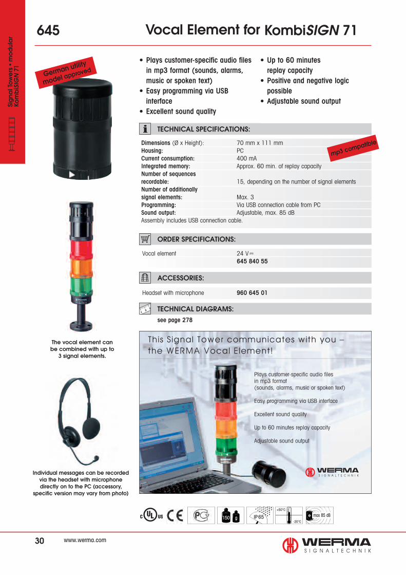
645 Vocal Element for KombiSIGN 71
• Plays customer-specific audio files in mp3 format (sounds, alarms,
music or spoken text)• Easy programming via USB interface• Excellent sound quality
• Up to 60 minutes replay capacity
• Positive and negative logic possible• Adjustable sound output
The vocal element can be combined with up to
3 signal elements.
Dimensions (Ø x Height): 70 mm x 111 mmHousing: PCCurrent consumption: 400 mAIntegrated memory: Approx. 60 min. of replay capacityNumber of sequences recordable: 15, depending on the number of signal elementsNumber of additionally signal elements: Max. 3Programming: Via USB connection cable from PCSound output: Adjustable, max. 85 dBAssembly includes USB connection cable.
Vocal element 24 V 645 840 55
DC
AC
AC/DC
Headset with microphone 960 645 01
Individual messages can be recordedvia the headset with microphonedirectly on to the PC (accessory,
specific version may vary from photo)
Plays customer-specific audio filesin mp3 format(sounds, alarms, music or spoken text)
Easy programming via USB interface
Excellent sound quality
Up to 60 minutes replay capacity
Adjustable sound output
German utility
model approv
ed
mp3 compatibl
e
TECHNICAL SPECIFICATIONS:
ORDER SPECIFICATIONS:
ACCESSORIES:
TECHNICAL DIAGRAMS: see page 278

IP65
+50°C
-20°C
max100 dB125 g
31
PLC
ADDITIONAL INFORMATION:
The siren element adjusts its sound output through continual measurement of the ambient noise level. The emitted tone is c. 5 dB louder than the background noiselevel. The warning signal can always be heard without being irritatingly loud for people in the sounder’s vicinity.
TECHNICAL DIAGRAMS: see page 278
Voltage: 24 VCurrent consumption: < 150 mA 645 810 55
DC
AC
AC/DC
ORDER SPECIFICATIONS:
Dimensions (Ø x Height): 70 mm x 111 mmHousing: PCTone type: Pulse toneTone frequency: 2.5 KHzSound output: 80 dB - max. 100 dB
TECHNICAL SPECIFICATIONS:
Loud enough
yet
not disturbing
!
www.werma.com
• Automatic sound output adjust- ment between 80 and 100 dB• Sound output is c. 5 dB louder than the background noise level
• Continual measurement of the ambient noise level• Ideal for applications with changing ambient sound levels
Signa
l Tow
ers ●
modular
Kom
biS
IGN
71
645 Siren Element with self-adjustingsound output for KombiSIGN 71
Patent
approved

32
+50°C
-20°CIP6597 g
ORDER SPECIFICATIONS:
Direct triggering via USB InterfaceIn many applications, it is necessary to indicate operating states or faults by means of an optical signal. A PLC or machine controller is not available in all areas; PCs are often alsoconnected to control the machines. The optimal solution for this is the terminal element withUSB interface for KombiSIGN 70, 71 and Kompakt 71.
This innovation in the field of signal towers is controlled directly from the PC and can therefore be put into operation easily and in an uncomplicated manner. Neither a separatepower supply nor additional hardware is required because the terminal element with USBinterface is based on a standard USB interface.
640
Terminal element USB 24 V 640 840 00
DC
AC
AC/DC
Base with integrierted tube 975 840 10Tube mounting with base for tube (metal) 975 840 91
Tube Ø 25 mm100 mm long 975 845 10 250 mm long 975 840 25400 mm long 975 840 40 600 mm long 975 840 60800 mm long 975 840 80 1000 mm long 975 840 03
• Direct triggering of signal tower elements via USB Interface• Easy activation• Can be combined with up to 4 signal elements
Terminal Element with USB Interface for KombiSIGN 71
• Assembly includes installation software and USB connection cable• No additional power supply necessary• No additional hardware needed
Dimensions (Ø x Height): 70 mm x 26.5 mm Material: PA-GF, shock resistantFixing: Tube mounting Connection: USB-Bus Assembly includes installation software and USB connection cable (AWG 22), 2 m long Maximum permitted length of USB cable (min. AWG 22): 7 mCurrent carrying capacityImax: 100 mA
Direct triggering of the signal tower via USB Interface
Base for tube (metal) and tube Ø 25 mm (accessories)
www.werma.com
Signa
l Tow
ers ●
modular
Kom
biS
IGN
71
TECHNICAL DIAGRAMS: see page 277
ADDITIONAL INFORMATION:
ACCESSORIES:
TECHNICAL SPECIFICATIONS:

33
The KombiSIGN Signal Towers 71can be coated in any colour
within the RAL spectrum
www.werma.com
Signa
l Tow
ers ●
modular
Kom
biS
IGN
71
Please stat
e the
required RA
L number
ACCESSORIES:
ORDER SPECIFICATIONS TERMINAL ELEMENTS:
CAGE CLAMP® Screw terminalTerminal element for tube mounting,coated, including cap 640 710 00 640 730 00
Terminal element for bracket or base mounting, coated including cap and seal 640 700 00 640 720 00
• Signal towers in customer- specific colours• Meets the demands of anincreasing design preference
• Simple ordering procedure• Complete range of RAL colours available• High protection rating IP 65
Base with integrated tube, coated Ø 25 mm, 110 mm long, plastic, incl. rubber seals 960 000 24
Bracket for 1-sided mounting, coated, incl. rubber seals 960 000 22
Please state the required RAL number and colourfinish (matt or gloss) with each of your orders. Slight colour deviations are possible.
Dimensions Terminal Elements (Ø x Height): 70 mm x 26.5 mmHousing Terminal Elements: PA-GF, fibreglass, high-impact, Cap: PCConnection: CAGE CLAMP® technology max. 2.5 mm2
Contact protection according to VDE
Cable entry: Cable diameter max. 14 mmNumber of modules possible: Max. 5Minimum order quantity: 10 piecesDelivery time: By arrangementColour Finish: Matt or gloss
640 KombiSIGN 71 in customer- specific coloured coatings
The Signal Towers are designed to harmonise with the colour of the customer‘s product design,
guaranteeing a uniform appearance ADDITIONAL INFORMATION:
TECHNICAL DIAGRAMS: see page 277
TECHNICAL SPECIFICATIONS:

34
160 g
+50°C
-20°CIP65
960
TECHNICAL DIAGRAMS: see page 292 + 293
ORDER SPECIFICATIONS:
TECHNICAL SPECIFICATIONS:
Interface box 960 000 16Interface box incl. accessories 960 000 17
Interface Boxfor KombiSIGN 71
• Up to 127 signal towers can be adressed (RS 485)• Monitoring of each element possible• Versions for Bus systems available on request
Assembly:Interface Box and
terminal element for signal tower KombiSIGN 71
Assembly without laptop and signal tower elements
Dimensions of theInterface box (L x H x W): 80 x 66 x 82 mmMaterial: ABSDrive: 24 VInterfaces: RS 232, RS 485
Assembly: 960 000 16 960 000 17
• Interface box • Interface box • Terminal element • Terminal element • 2 cable glands • 1 cable gland M16 M16 • Network appliance with cable • Connection cable RS 232, 2 m long, with Sub-D 9-pin and socket for power supply • CD with demonstration programme • Programming handbook
DC
AC
AC/DC
www.werma.com
Signa
l Tow
ers ●
modular
Kom
biS
IGN
71
• Direct triggering from PC via RS 232 or RS 485 interfaces• Programming of various drives via serial interface• Triggering of up to 4 independent elements of a KombiSIGN signal tower

35
+50°C
-20°CIP65
1 2 3 4
ORDER SPECIFICATIONS:
ACCESSORIES:
QUICK AND SIMPLE MOUNTING:
TECHNICAL DIAGRAMS: see page 293
TECHNICAL SPECIFICATIONS:
Vertical alignment of signal towerseven on sloping surfaces
Place the upper andlower parts together at the desired angle
Place the upper andlower parts together at the desired angle
Attach the upper partdirectly onto the signaltower tube. Insert theconnection cable
Place the lower part of the Foldaway Base in thedesired position
Foldaway base for KombiSIGN 71 960 000 30
Tube Ø 25 mm, plastic 45 mm long, for direct mounting of the Terminal Elementonto the Foldaway Base 960 000 31
Tube Ø 25 mm, all anodized aluminium, see page 21
Cable gland M 16 x 1.5 mm 960 000 04
Dimensions (Ø x Height): 70 mm x 117 mmMaterial: PA-GF Cable diameter: Max. 14 mmAssembly: Incl. rubber sealsFixing: Vertical, horizontal Positioning in 7.5° stepsSuitable for: Tube, Ø 25 mm, all anodized aluminium, not included in assembly (accessory)
When transporting the machine,the signal tower can be folded
away in a few simple steps
960 Foldaway Base for KombiSIGN 71
Maximum stability even with strongshocks and vibrations thanks to the
locking mechanism
• The signal tower can be folded away while still connected• Minimises packaging costs and optimises machine transportation • Simple mounting and cable entry –for up to Ø 14 mm
• Vertical alignment of signal towerseven on sloping surfaces
• Positioning in 7.5° steps, markings for 30, 45, 60 or 90 degrees
German utility
model approv
ed
www.werma.com
Signa
l Tow
ers ●
modular
Kom
biS
IGN
71

36
Contact box for cable exit at sideOrder no. 975 840 01
Tube with clampOrder no.960 000 18
Adaptor forsingle holemountingOrder no.960 000 25
Base with integratedtubeOrder no.975 840 10
Tube Ø 25 mm, all anodized Order no.100 mm long 975 845 10250 mm long 975 840 25400 mm long 975 840 40600 mm long 975 840 60800 mm long 975 840 801000 mm long 975 840 03
Base for Tube, plasticOrder no. 975 840 90
Base for Tube, metalOrder no. 975 840 91
Foldaway BaseOrder no. 960 000 30
Tube Ø 25 mm, plastic, only forFoldaway Base, 45 mm longOrder no. 960 000 31
Bracket for base mountingOrder no. 960 000 02
Contact box for cable exit at sideOrder no. 975 840 01
Contact box with magnetic base and cable exit at sideOrder no. 975 840 04
Bracket for 1-sided mountingOrder no. 975 840 85
Bracket for 2-sided mountingOrder no. 975 840 86
Bracket for base mountingwith concealed cable entryOrder no. 960 000 14
Bracket for tube mountingOrder no. 960 000 01
This is how you can assemble your KombiSIGN 70 signal tower!
STEP 1Select the required optical or audible elements.
Many KombiSIGN highlights are also available (for detailssee page 37).
Audible Signal Elements• Buzzer Element• Siren Element• Vocal Element
Optical Signal Elements• (LED) Permanent Light• LED Permanent Light ultrabright• (LED) Flashing Light• LED EVS Element• LED Blinking Light• LED Rotating Light
Base Mounting Tube Mounting
Signal Tower KombiSIGN 70Signa
l Tow
ers ●
modular
Kom
biS
IGN
70
STEP 4Where appropriate, select a baseand the desired length (only fortube mounting).
STEP 5Where appropriate, select thebracket and the contact box.
The Signal Devices Site on the Internet:www.werma.com
With our new signal tower configuratoryou can put together your own indi-vidual signal tower.
STEP 2Select the appropriate mountingoption for your application.
STEP 3Select the correct terminal element for your mounting option.
NEW
Terminal element for base mountingOrder no. 840 085 00
Terminal element for tube mountingOrder no. 840 080 00
www.werma.com
TIP

37
The Highlights for KombiSIGN 70
NEW
NEW
NEW
NEW
This Signal Tower speaks to you!
WIN – Wireless InformationNetwork
• Economical wireless-based Machine Data Collection system (MDC system)
• Central monitoring of a wide range of different machines via PC
See page 43
KombiSIGNreflect
• Simple monitoring of signal towers out of view
• Signal tower ”reflection“ to a central location
See page 44
LED Permanent LightElement ultrabright
• Up to 20 times brighter than conventional LED elements
• Maximum brightness via intelligent LED control
See page 47
LED EVS Element
• Attention-grabbing flickering light
• Extremely powerful signal effect
• Random sequence of light signals prevents acclimatisationeffect
See page 48
Foldaway base
• Enables signal towers to be folded down completely, even when connected
• Vertical alignment of signal towers even on sloping surfaces
See page 53
Vocal Element
• Plays customer-specific audio files in mp3 format (sounds, alarms, music or spoken text)
• Easy programming via USB interface
• Up to 60 minutes replay capacity
See page 49
GSM Transmitter Element
• Malfunction signalled by signal tower is transmitted via SMSor call to a mobile phone
• Activation without the need for programming
• No additional power supply needed
See page 45
LED Flashing Light Element
• Extremely long life duration up to 50,000 hrs
• Low current consumption• Shock-proof and vibration resistant
See page 38
AS-Interface Element
Customer specific coloured coatings
Siren Element with self-adjusting sound output
Terminal Element with USB Interface
• LEDs indicate current status• 31 or 62 addresses• Available with standard or A/B technology
See page 46
• Signal towers in customer-specific colours – complete range of RAL colours available
• Meets the demands of an increasing design orientation
See page 52
• Sound output is automatically adjusted to the backgroundnoise level
• Warning tone can be heard without being irritatingly loud
See page 50
• Direct triggering of signal tower elements via USB Interface
• Easy activation
See page 51
Signa
l Tow
ers ●
modular
Kom
biS
IGN
70
www.werma.com

IP54
+50°C
-20°C
105 dB2
Ws
38
PLC
840
Improved
light effect
24 V
Signa
l Tow
ers ●
modular
Kom
biS
IGN
70
TECHNICAL SPECIFICATIONS:
NEW
Base with tube (accessory)
Tube mounting (accessory)
Bracket (accessory)
Signal Tower KombiSIGN 70
• Wide range of optical and audible elements• Elements can be assembled as required
• Signal tower system 70 mm Ø with modular construction• 360° visibility
www.werma.com
Dimensions (Ø x Height): Terminal element: 70 mm x 30.5 mm Light element: 70 mm x 65.5 mm Audible element: 70 mm x 72/79/110 mmHousing: Terminal element: PA fibreglass, high-impact Cap: PC/ABS-BlendLens: PC, transparent Audible and ASI elements: PC/ABS-BlendFixing: Base mounting Tube mounting, for tube Ø 25 mm Bracket mounting (accessory)Socket: Bayonet, B15d, for bulb max. 7 WConnection: Screw terminal max. 2.5 mm2
Contact protection according to VDECable entry: Cable diameter max. 14 mmElement seal: Pre-mounted with each moduleProtection rating: Light elements: IP 54 Audible elements: IP 54 (Order no. 844 123 55 = IP 40)Number of modules possible: Max. 5 / with 2-sided bracket max. 10 elements
Permanent light element 12 - 240 V Bulb not included in assembly
LED Permanent light element 24 V 115 V 230 VCurrent consumption: < 30 mA < 20 mA < 20 mA
LED Permanent light element ultrabright 24 VLife duration: Up to 50,000 hrsCurrent consumption: Max. 190 mAUp to 20 times brighter than conventional LED beacons.
Flashing light element (Xenon) 24 V 115 V 230 VLife duration: 4 x 10⁶ flashesCurrent consumption: 125 mA 22 mA 15 mAReduced for AS-Interface: 80 mAFlash frequency: c. 1 Hz
LED Flashing light element 24 VLife duration: 50,000 hrsCurrent consumption: < 30 mA (red/yellow) < 25 mA (green/clear/blue)Flash frequency: c. 1 Hz (Double Flash)
LED EVS* element 24 VCurrent consumption: 350 mA (red/yellow) 250 mA (green/clear/blue)* EVS = Enhanced Visibility System
LED Blinking light element 24 V 115 V 230 VCurrent consumption: 25 mA 25 mA 25 mABlink frequency: c. 1 Hz
LED Rotating light element 24 VCurrent consumption: 70 mA Rotation frequency: c. 120 r.p.m.
DC
AC
AC/DC
DC
AC
AC/DC
DC
AC
AC/DC
DC
AC
AC/DC
DC
AC
AC/DC
DC
AC
AC/DC
DC
AC
AC/DC
DC
AC
AC/DCDC
AC
AC/DC
DC
AC
AC/DC
DC
AC
AC/DC
DC
AC
AC/DC
DC
AC
AC/DC
DC
AC
AC/DC

39
Compare the pri
ces
and advant
ages of
an LED Flash
ing light
Improved
light effect
NEW
Life duratio
n
up to 50,00
0 hrs
ORDER SPECIFICATIONS OPTICAL ELEMENTS:
Signa
l Tow
ers ●
modular
Kom
biS
IGN
70
TECHNICAL DIAGRAMS: see page 285 onwards
LED EVS element
LED element
Permanent light, clear with info
(LED) Permanent/Flashing light element
Permanent light element 12-240 V red 840 100 00 green 840 200 00 yellow 840 300 00 clear 840 400 00 blue 840 500 00 Bulb not included in assembly. Accessories see page 42.
LED Permanent light element 24 V 115 V 230 Vred 843 100 55 843 100 67 843 100 68green 843 200 55 843 200 67 843 200 68yellow 843 300 55 843 300 67 843 300 68clear 843 400 55 843 400 67 843 400 68blue 843 500 55 843 500 67 843 500 68
LED Permanent light element ultrabright 24 V red 843 180 55 green 843 280 55 yellow 843 380 55 clear 843 480 55 blue 843 580 55
Flashing light (Xenon) 24 V (ASI) 24 V 115 V 230 Vred 842 110 55 842 100 55 842 100 67 842 100 68green 842 210 55 842 200 55 842 200 67 842 200 68yellow 842 310 55 842 300 55 842 300 67 842 300 68clear 842 410 55 842 400 55 842 400 67 842 400 68blue 842 510 55 842 500 55 842 500 67 842 500 68
LED Flashing light element 24 V red 843 120 55 green 843 220 55 yellow 843 320 55clear 843 420 55blue 843 520 55
LED EVS element 24 V red 843 140 55 green 843 240 55 yellow 843 340 55 clear 843 440 55 blue 843 540 55
LED Blinking light element 24 V 115 V 230 Vred 843 110 55 843 110 67 843 110 68green 843 210 55 843 210 67 843 210 68yellow 843 310 55 843 310 67 843 310 68clear 843 410 55 843 410 67 843 410 68blue 843 510 55 843 510 67 843 510 68
LED Rotating light element 24 V red 843 130 55 green 843 230 55 yellow 843 330 55 clear 843 430 55 blue 843 530 55
Further voltages on request.
DC
AC
AC/DC
DC
AC
AC/DC
DC
AC
AC/DC
DC
AC
AC/DC
DC
AC
AC/DC
DC
AC
AC/DC
DC
AC
AC/DC
DC
AC
AC/DC
DC
AC
AC/DC
DC
AC
AC/DC
DC
AC
AC/DC
DC
AC
AC/DC
DC
AC
AC/DC
DC
AC
AC/DC
DC
AC
AC/DC
www.werma.com

40
NEW
NEW
NEW
NEW
Signa
l Tow
ers ●
modular
Kom
biS
IGN
70
Audible element844 123 55
Buzzer element 24 V 115 V 230 V85 dB, 25 mA, IP 54, 844 118 55 844 118 67 844 118 68Continuous or pulse tone
Siren element 24 V105 dB, 150 mA, IP 40 844 123 55Continuous tone alternating no UL / CSA approval
Multi-functional Siren 24 V / 80 mA 115 V / 40 mA 230 V / 40 mA100 dB, IP 54, 844 126 55 844 126 67 844 126 688 different tones, adjustable sound output
Multi-functional Siren, 24 Vcan be triggered externally 844 126 95100 dB, 80 mA, IP 65, 7 diff. tones can be triggered externally, adjustable sound output,number of tones depending on the number of optical elements.
Siren element with 24 Vself-adjusting sound output 844 810 55Technical specifications see page 51.
Available: 1st Quarter 2011.
DC
AC
AC/DC
DC
AC
AC/DC DC
AC
AC/DC
DC
AC
AC/DC
DC
AC
AC/DC
DC
AC
AC/DC
DC
AC
AC/DC
DC
AC
AC/DC
DC
AC
AC/DC
840 Signal Tower KombiSIGN 70
GSM transmitter element
Vocal element
WIN system for KombiSIGN 70 860 840 01Technical specifications see page 43.
WIN slave for KombiSIGN 70 860 840 02Technical specifications see page 43.
KombiSIGN 70 reflect 861 840 01Technical specifications see page 44.
GSM Transmitter Element 24 V for KombiSIGN 70 840 700 55Technical specifications see page 45.
Vocal Element 24 Vfor KombiSIGN 70 844 840 55Technical specifications see page 49.
AS-Interface Element Standard Slave A/B-Slavefor KombiSIGN 70 24 V 24 V 840 830 55 840 810 55Technical specifications see page 46.
DC
AC
AC/DC
DC
AC
AC/DC
DC
AC
AC/DC
DC
AC
AC/DC
Terminal element with cap
Terminal element for tube mounting
incl. cap 840 080 00
Terminal element for bracket or base mounting incl. cap und rubber seal 840 085 00
Terminal element with USB Interface (for tube mounting) 840 580 00 Technical specifications see page 51.
ORDER SPECIFICATIONS TERMINAL ELEMENTS :
ORDER SPECIFICATIONS AUDIBLE ELEMENTS:
ORDER SPECIFICATIONS KOMBISIGN-HIGHLIGHTS:
www.werma.com

41
Signa
l Tow
ers ●
modular
Kom
biS
IGN
70
Accessories for Signal Tower KombiSIGN 70
Contact box for cable exit at side, 975 840 01with mounting material
Contact box with magnetic base 975 840 04and cable exit at side
Bracket for tube mounting 960 000 01with cable gland
Bracket for surface mounting 960 000 02with cable gland
Base for tube mounting Ø 25 mm, 975 840 90plastic, incl. rubber seal
Tube Ø 25 mm, plastic 960 000 31for mounting the Terminal Element directly on the Foldaway Base
Foldaway Base incl. rubber seals, suitable for tube, 960 000 30Ø 25 mm, all anodized aluminium (Technical specifications see page 53)
Bracket for 1-sided 975 840 85mounting, incl. rubber seals
Bracket for 2-sided 975 840 86mounting, incl. rubber seals
Tube with clamp, Ø 25 mm 960 000 18250 mm long, with cable gland
Base for tube mounting Ø 25 mm, metal, incl. rubber seal, 975 840 91recommended for tube lengths of 400 mm and longer
Base with integrated tube, Ø 25 mm, 975 840 10110 mm long, plastic, incl. rubber seal
Adaptor for tube mounting, 975 840 02Ø 25 mm / 1/2” NPT thread
Adaptor for single hole mounting 960 000 25Ø 25 mm, M 18
Cable gland for 960 000 04surface mounting M 16 x 1.5 mm
Bracket for base mounting 960 000 14with concealed cable entry, incl. rubber seals
Tube Ø 25 mm, all anodized aluminium 100 mm long 975 845 10 250 mm long 975 840 25 400 mm long 975 840 40 600 mm long 975 840 60 800 mm long 975 840 801000 mm long 975 840 03
TECHNICAL DIAGRAMS: see page 292 onwards
ORDER SPECIFICATIONS ACCESSORIES:
www.werma.com
42
number „6” 975 840 56number „7” 975 840 57number „8” 975 840 58number „9” 975 840 59number „10” 975 840 92arrow 975 840 62
Accessories for Signal Tower KombiSIGN 70
Bulb BA15d, total length max. 42 mm(for permanent light 641)12 V, 5 Watt 955 840 3424 V, 5 Watt 955 840 3530 V, 5 Watt 955 840 32115 V, 5 Watt 955 840 57230 V, 5 Watt 955 840 38
LED bulb BA15d, total length max. 42 mm(for permanent light 840) Voltage 24 V 115 V 230 VCurrent consumption < 45 mA < 15 mA < 15 mAred 956 100 75 956 100 67 956 100 68green 956 200 75 956 200 67 956 200 68yellow 956 300 75 956 300 67 956 300 68white 956 400 75 956 400 67 956 400 68blue 956 500 75 956 500 67 956 500 68
DC
AC
AC/DC
DC
AC
AC/DC
DC
AC
AC/DC
Indication Board
• Indication Board for one to five modules• Simple mounting onto signal tower tube• Ample space for written information• Simply break off unwanted segments
Dimensions of indication board (W x H): 153 x 345 mm
Surface area per section (W x H): c. 140 x 50 mm
Material: PMMA
Assembly: Indication board (5 sections)
incl. mounting material
Mounting: Fixing only possible on 25 mm diameter tube
Indication board 960 000 05
Info transparencies: To place inside optical elements, not for use in Flashing Light, LED EVS, LED Flashing Light and LED Permanent Light Element ultrabright.
neutral 975 840 49number „0” 975 840 50number „1” 975 840 51number „2” 975 840 52number „3” 975 840 53number „4” 975 840 54number „5” 975 840 55
You will find an overview of the entire range of accessories for KombiSIGN Signal Towerson pages 60 and 61.
ADDITIONAL INFORMATION:
ORDER SPECIFICATIONS ACCESSORIES:
TECHNICAL DIAGRAMS: see page 290 + 291
Fault
Refill
Overheating
Station 2
Machine inoperation
Signa
l Tow
ers ●
modular
Kom
biS
IGN
70
www.werma.com

43
+50°C
-20°CIP54 PLC
• Reduction of reaction times, repair and maintenance require- ments and costs• No additional wiring as existing WERMA signal towers can be used• Downtime analysis
TECHNICAL DIAGRAMS: see page 288
ADDITIONAL INFORMATION:
TECHNICAL SPECIFICATIONS:
ORDER SPECIFICATIONS:
WIN system for KombiSIGN 70 860 840 01Assembly: WIN master, 3 WIN slaves KombiSIGN 70 (pre-configured), Software
WIN slave for KombiSIGN 70 860 840 02To expand WIN system. The network can be expanded to up to 50 WIN slaves.
* WIN = Wireless Information NetworkFurther informationen can be found in the chapter „Tech-Talk“ beginning on page 320.
With the supplied software, users can wirelessly monitor
their machinery via PC
The software enables usersto analyse productivity and
increase the efficiencyof their machines
The software displays the statusof the signal towers integrated
into the wireless network
• Economical wireless-based Machine Data Collection system (MDC system)• Central monitoring of a wide range of different machines via PC• Relevant machine information at a glance
WIN slaveDimensions (Ø x Height): 70 mm x 65.5 mmHousing: PC, blackConnection: BayonetOperating voltage: 24 VCurrent consumption: 40 mA
WIN masterDimensions (L x H x W): 76 mm x 30 mm x 80 mm (without antenna)Housing: ABS, blackConnection: Via USBOperating voltage: Via USBCurrent consumption: < 100 mASuitable for: Windows 2000, Windows XP, Windows Vista, Windows 7
Wireless connectionISM frequency: 868 MHz (WIN conforms to the EU’s EN 300220 harmonised standard and can thus be used in all EU member countries. Further countries upon request.)
Transmission range: Up to 300 m (unobstructed line of sight) Every slave simultaneously functions as a “repeater”, enabling the transmission range to be significantly increased.
DC
AC
AC/DC
“WIN system” is immediately readyfor use: Fit the slaves in the existing
signal towers and connect themaster to the PC
NEW
860 WIN* for KombiSIGN 70
Patent pen
ding
Signa
l Tow
ers ●
modular
Kom
biS
IGN
70
www.werma.com

44
+50°C
-20°CIP65 PLC
NEW
Signa
l Tow
ers ●
modular
Kom
biS
IGN
70
TECHNICAL DIAGRAMS: see page 289
ADDITIONAL INFORMATION:
Simply fit the KombiSIGN reflect slave to the signal tower on the
machine
861 KombiSIGN reflect for KombiSIGN 70
• KombiSIGN reflect is integrated into existing WERMA signal towers• No additional wiring costs • Simple commissioning due to pre-configured modules
ORDER SPECIFICATIONS:
TECHNICAL SPECIFICATIONS:
KombiSIGN 70 reflect 861 840 01
SlaveDimensions (Ø x Height): 70 mm x 65.5 mmHousing: PC, blackConnection: BayonetOperating voltage: 24 VCurrent consumption: 40 mA
MasterDimensions (Ø x Height): 70 mm x 65.5 mm (without antenna)Housing: PC, blackConnection: BayonetOperating voltage: 24 VCurrent consumption: 40-90 mA
Wireless connectionISM frequency: 868 MHz (KombiSIGN reflect conforms to the EU’s EN 300220 harmonised standard and can thus be used in all EU member countries. Further countries upon request.) Transmission range: Up to 300 m (unobstructed line of sight)
DC
AC
AC/DC
DC
AC
AC/DC
• Simple monitoring of signal towers out of view• Signal tower “reflection” to a central location• Shortening of reaction times and reduction of costs
The slave sends the status directlyto the master, and reflects the
status of the signal tower installedon the machine
Remote transmission via wireless signal with a maximum range of upto 300 m (unobstructed line of sight)
Simple monitoring of signal towers out of view
www.werma.com
Signal tower “reflection”WERMA Signaltechnik provides a simple solution for the remote wireless monitoring of machinery. The new “KombiSIGN reflect” kit can be integrated into existing signal towerswhich are already installed on your machines. KombiSIGN reflect “reflects“ the status of the machine to a signal tower within your line of sight.
This enables you to wirelessly monitor machines situated at a greater distance and respond quickly to malfunctions. With KombiSIGN reflect, even machines which where not previously network-capable can now be remotely monitored.
Further informationen can be found in the chapter ”Tech-Talk“ on page 324.

45
+50°C
-20°C170 g IP54
Signa
l Tow
ers ●
modular
Kom
biS
IGN
70
ORDER SPECIFICATIONS:
TECHNICAL SPECIFICATIONS:
TECHNICAL DIAGRAMS: see page 285
Class 2
GSM Transmitter Element 24 V 840 700 55
DC
AC
AC/DC
Dimensions (Ø x Height): 70 mm x 65.5 mm (without antenna)Housing: PCCurrent consumption: 50 mAMax. current draw (momentary): 450 mAGSM frequency: 850, 900, 1800/1900 MHz Plug-in slot for SIM card: Integrated (SIM card is not included in assembly)Antenna connection: FME plug connector (bracket antenna included)
840 GSM Transmitter Element for KombiSIGN 70
• Unique Signal Tower solution• GSM transmitter element can be simply integrated into an existing signal tower• Activation without the need for programming
• Malfunction signalled by signal tower is transmitted via SMS to a mobile phone • No additional power supply needed• Also suitable for US frequencies (Quadband)
Also suitable for
US frequencies
www.werma.com
Patent
approved

46
IP54
+50°C
-20°C77 g
Standard Slave A/B-SlaveClass 2
Approval No. 66301 Approval No. 66202
Signa
l Tow
ers ●
modular
Kom
biS
IGN
70
Cable not included in assembly
TECHNICAL DIAGRAMS: see page 285
ORDER SPECIFICATIONS:
TECHNICAL SPECIFICATIONS:
LEDs displays the current status
ADDITIONAL INFORMATION:
• Voltage supply switchable from internal bus supply to additional external voltage supply• With addressing socket
• LEDs indicate current status• 31 or 62 addresses• Available with standard or A/B technology
AS-Interface Element Standard Slave A/B-Slave 840 830 55 840 810 55
Standard Slave A/B-SlaveNumber of addresses: Max. 31 Max. 62Number of signal elements: Max. 4 Max. 3IO-Code: 8 8ID-Code: F AID2-Code: – EOutputs: 4 semiconductor relays 3 semiconductor relaysApproved in accordance with: Spec. V 3.0 Spec. V 3.0
Specif. Power supplyAS-Interface Element: Via bus conduction Operating voltage: 25 V … 31.6 V according to the AS-Interface specificationReverse battery protection: Integrated Watchdog: Integrated Additional external voltage: 24 V +/- 10%
With internal add. voltage With external add. voltageCurrent carrying cap. Σ Imax: 200 mA 200 mA per signal elementCurrent consumption max: 250 mA 75 mAVoltage at signal element: 18 V - 24 V 24 V +/- 10%Short circuit/overload protection: Integrated Pre-fuse M 1.6 A
DC
AC
AC/DC
840 AS-Interface Element for KombiSIGN 70
The KombiSIGN Signal Towers 70 and 71 with AS-InterfaceElement are capable of total communication: Through simple integration of an AS-Interface Element the actuators are connectedto the networking system Actuator-Sensor-Interface – this con-siderably reduces complex wiring. The necessary power supply
(supply via bus or external) can be selected with a switch. This element is mounted as the first tier of the individual signal tower directly on top of the terminal element.(Further Information see page 319).
www.werma.com

47
+50°C
-20°CIP65 PLC
TECHNICAL DIAGRAMS: see page 285
TECHNICAL SPECIFICATIONS:
ORDER SPECIFICATIONS:
ADDITIONAL INFORMATION:
Signa
l Tow
ers ●
modular
Kom
biS
IGN
70
NEW
Maximum brightness viaintelligent LED control
The high level of brightnessguarantees good visibility –
even in direct sunlight
LED Permanent light element ultrabright 24 Vred 843 180 55 green 843 280 55yellow 843 380 55clear 843 480 55blue 843 580 55
DC
AC
AC/DC
Dimensions (Ø x Height): 70 mm x 65.5 mmLens: PC, transparentSeal: Pre-mounted with each elementNumber of modulespossible: 5, with 2-sided bracket max. 10Current consumption: Max. 190 mA
Sophisticated triggering Thanks to its sophisticated triggering, the innovative LED element “ultrabright” is up to 20 times brighter than conventional LED elements – making it almost certainly the brightestpermanent light that the world of signalling technology currently has to offer.
Furthermore, the intelligent electronics ensure that the LEDs operate at maximum brightn-ess, depending on the ambient and operating temperatures. The “ultrabright“ LED elementis therefore always working at its optimum, and the energy-saving LED technology ensures that power consumption iskept to a minimum.
Further informationen can be found in the chapter ”Tech-Talk“ beginning on page 325.
• Maximum brightness via intelligent LED control• Low current consumption and maintenance-free• Shock-proof and vibration- resistant
• Up to 20 times brighter than conventional LED elements• Extremely good visibility – even in direct sunlight• Life duration up to 50,000 hrs
843 LED Permanent Light Element ultrabright for KombiSIGN 70
Life duratio
n
up to 50,00
0 hrs
www.werma.com

48
+50°C
-20°CIP54 PLC
ADDITIONAL INFORMATION:
ORDER SPECIFICATIONS:
TECHNICAL SPECIFICATIONS:
TECHNICAL DIAGRAMS: see page 285
Patent pen
ding
Life duratio
n
up to 50,00
0 hrs
Integrated into the KombiSIGNSignal Towers, the new EVS
LED Element generates a highlyattention-grabbing signal
• Random sequence of light signals prevents acclimatisation effect• For signalling extremely hazardous situations and the need for immediate action
Voltage 24 V red 843 140 55green 843 240 55 yellow 843 340 55clear 843 440 55 blue 843 540 55
DC
AC
AC/DC
* EVS = Enhanced Visibility System or Enhanced Visibility SystemFurther informationen can be found in the chapter ”Tech-Talk“ on page 326.
EVS – Attention-grabbing light effect on neurobiological basisThe flickering of neon lamps and comparable light effects are highly effective at attrac-ting our attention. The neurobiological basis of this phenomenon is explained by a uni-versity scientist as follows: Light signals are processed in the human brain, not directly in the eye.
In order to be consciously registered there, incoming stimuli first have to pass through a form of filter. This filter has a “protective” function. During sleep it reduces disturbingstimuli to a minimum and assists in “overlooking” regular or continuous signals.
EVS – Flickering light without acclimatisation effectOn the basis of this understanding, WERMA’s R+D department set out to find a flickeringlight with a high degree of effectivity in attracting attention. In a multistage laboratoryexperiment 20 test candidates were asked to judge a series of different light signals andto determine the most eye-catching light. The result of the study was a stochastic flicke-ring light with optimal attention-grabbing characteristics: EVS – Enhanced VisibilitySystem! The light effect of this system is completely new and distinguishes it from all previous systems.
Dimensions (Ø x Height): 70 mm x 65.5 mmLens: PC, transparentSeal: Pre-mounted with each elementNumber of modulespossible: 5, with 2-sided bracket max. 10Current consumption: red / yellow: 200 mA green / blue / clear: 150 mA
843 LED EVS* Element for KombiSIGN 70
• Attention-grabbing flickering light• Developed on a neurobiological basis• Extremely powerful signal effect
Signa
l Tow
ers ●
modular
Kom
biS
IGN
70
Optic chiasm
Brain
Right eye
Optic nerveLeft eye
Leftvisua
l field Right visual field
The way in which the brain processes visual stimuli formed the basis for the development of
the new EVS technology
www.werma.com

49
150 g
+50°C
-20°CIP54 max 85 dB
843 LED EVS* Element for KombiSIGN 70
Headset with microphone 960 645 01
The vocal element can be combined with up to
3 signal elements
Individual messages can be recordedvia the headset with microphonedirectly on to the PC (accessory,
specific version may vary from photo)
Plays customer-specific audio filesin mp3 format(sounds, alarms, music or spoken text)
Easy programming via USB interface
Excellent sound quality
Up to 60 minutes replay capacity
Adjustable sound output
Vocal element 24 V 844 840 55
DC
AC
AC/DC
Dimensions (Ø x Height): 70 mm x 111 mmHousing: PCCurrent consumption: 400 mAIntegrated memory: Approx. 60 min. of replay capacityNumber of sequences recordable: 15, depending on the number of signal elementsNumber of additionally signal elements: Max. 3Programming: Via USB connection cable from PCSound output: Adjustable, max. 85 dBAssembly includes USB connection cable.
Signa
l Tow
ers ●
modular
Kom
biS
IGN
70
• Plays customer-specific audio files in mp3 format (sounds, alarms,
music or spoken text)• Easy programming via USB interface• Excellent sound quality
• Up to 60 minutes replay capacity
• Positive and negative logic possible• Adjustable sound output
844 Vocal Element for KombiSIGN 70
mp3 compatibl
e
TECHNICAL DIAGRAMS: see page 286
ACCESSORIES:
ORDER SPECIFICATIONS:
TECHNICAL SPECIFICATIONS:
www.werma.com
German utility
model approv
ed

50
IP54
+50°C
-20°C
max100 dB125 g PLC
TECHNICAL SPECIFICATIONS:
ORDER SPECIFICATIONS:
NEW
Loud enough
yet
not disturbing
!
ADDITIONAL INFORMATION:
TECHNICAL DIAGRAMS: see page 286
Signa
l Tow
ers ●
modular
Kom
biS
IGN
70
844 Siren Element with self-adjusting sound output for KombiSIGN 70
www.werma.com
The siren element adjusts its sound output through continual measurement of the ambient noise level. The emitted tone is c. 5 dB louder than the background noiselevel. The warning signal can always be heard without being irritatingly loud for people in the sounder’s vicinity.
Voltage: 24 VCurrent consumption: < 150 mA 844 810 55
DC
AC
AC/DC
Dimensions (Ø x Height): 70 mm x 111 mmHousing: PCTone type: Pulse toneTone frequency: 2.5 KHzSound output: 80 dB - max. 100 dB
• Automatic sound output adjust- ment between 80 and 100 dB• Sound output is c. 5 dB louder than the background noise level
• Continual measurement of the ambient noise level• Ideal for applications with changing ambient sound levels
Patent
approved

51
+50°C
-20°CIP5497 g
ADDITIONAL INFORMATION:
ORDER SPECIFICATIONS:
ACCESSORIES:
TECHNICAL SPECIFICATIONS:
TECHNICAL DIAGRAMS: see page 285
Direct triggering of the signal tower via USB Interface
Base for tube (metal) and tube Ø 25 mm (accessories)
Terminal element USB 24 V 840 580 00
DC
AC
AC/DC
840
Base with integrierted tube 975 840 10Tube mounting with base for tube (metal) 975 840 91
Tube Ø 25 mm100 mm long 975 845 10 250 mm long 975 840 25400 mm long 975 840 40 600 mm long 975 840 60800 mm long 975 840 80 1000 mm long 975 840 03
Terminal Element with USB Interface for KombiSIGN 70
Dimensions (Ø x Height): 70 mm x 30.5 mm Material: PA-GF, shock resistantFixing: Tube mounting Connection: USB-Bus Assembly includes installation software and USB connection cable (AWG 22), 2 m long Maximum permitted length of USB cable (min. AWG 22): 7 mCurrent carrying capacityImax: 100 mA
Direct triggering via USB InterfaceIn many applications, it is necessary to indicate operating states or faults by means of an optical signal. A PLC or machine controller is not available in all areas; PCs are often alsoconnected to control the machines. The optimal solution for this is the terminal element withUSB interface for KombiSIGN 70, 71 and Kompakt 71.
This innovation in the field of signal towers is controlled directly from the PC and can therefore be put into operation easily and in an uncomplicated manner. Neither a separatepower supply nor additional hardware is required because the terminal element with USBinterface is based on a standard USB interface.
Signa
l Tow
ers ●
modular
Kom
biS
IGN
70
www.werma.com
• Automatic sound output adjust- ment between 80 and 100 dB• Sound output is c. 5 dB louder than the background noise level
• Continual measurement of the ambient noise level• Ideal for applications with changing ambient sound levels

52
ADDITIONAL INFORMATION:
TECHNICAL DIAGRAMS: see page 285
ACCESSORIES:
Please stat
e the
required RA
L number
ORDER SPECIFICATIONS TERMINAL ELEMENTS:
TECHNICAL SPECIFICATIONS:
Screw terminalTerminal element for tube mounting,coated, including cap 840 780 00
Terminal element for Bracket- or base mounting, coated including cap and seal 840 785 00
• Signal towers in customer- specific colours• Meets the demands of anincreasing design preference
• Simple ordering procedure• Complete range of RAL colours available
Base with integrated tube, coated Ø 25 mm, 110 mm long, plastic, incl. rubber seals 960 000 24
Bracket for 1-sided mounting, coated, incl. rubber seals 960 000 22
Please state the required RAL number and colourfinish (matt or gloss) with each of your orders. Slight colour deviations are possible.
Dimensions Terminal Elements (Ø x Height): 70 mm x 26.5 mmHousing Terminal Elements: PA-GF, fibreglass, high-impact, Cap: PCConnection: CAGE CLAMP® technology max. 2.5 mm2
Contact protection according to VDE
Cable entry: Cable diameter max. 14 mmNumber of modules possible: Max. 5Minimum order quantity: 10 piecesDelivery time: By arrangementColour Finish: Matt or gloss
The Signal Towers are designed to harmonise with the colour of the customer‘s product design,
guaranteeing a uniform appearance
Signa
l Tow
ers ●
modular
Kom
biS
IGN
70
840 KombiSIGN 70 in customer- specific coloured coatings
www.werma.com
The KombiSIGN Signal Towers 70can be coated in any colour
within the RAL spectrum

53
+50°C
-20°CIP54
1 2 3 4
Signa
l Tow
ers ●
modular
Kom
biS
IGN
70
ORDER SPECIFICATIONS:
ACCESSORIES:
QUICK AND SIMPLE MOUNTING:
TECHNICAL DIAGRAMS: see page 293
TECHNICAL SPECIFICATIONS:
Vertical alignment of Signal Towerseven on sloping surfaces
Place the upper andlower parts together at the desired angle
Place the upper andlower parts together at the desired angle
Attach the upper partdirectly onto the signaltower tube. Insert theconnection cable
Place the lower part of the Foldaway Base in thedesired position
Foldaway base for KombiSIGN 70 960 000 30
Tube Ø 25 mm, plastic 45 mm long, for direct mounting of the Terminal Elementonto the Foldaway Base 960 000 31
Tube Ø 25 mm, all anodized aluminium, see page 41
Cable gland M 16 x 1.5 mm 960 000 04
Dimensions (Ø x Height): 70 mm x 117 mmMaterial: PA-GF Cable diameter: Max. 14 mmAssembly: Incl. rubber sealsFixing: Vertical, horizontal Positioning in 7.5° stepsSuitable for: Tube, Ø 25 mm, all anodized aluminium, not included in assembly (accessory)
When transporting the machine,the signal tower can be folded
away in a few simple steps
960 Foldaway base for KombiSIGN 70
Maximum stability even with strongshocks and vibrations thanks to the
locking mechanism
• The signal tower can be folded away while still connected• Minimises packaging costs and optimises machine transportation • Simple mounting and cable entry –for up to Ø 14 mm
• Vertical alignment of signal towerseven on sloping surfaces
• Positioning in 7.5° steps, markings for 30, 45, 60 or 90 degrees
German utility
model approv
ed
www.werma.com

54
NEW
This is how you can assemble your KombiSIGN 50 signal tower!
STEP 1Select the required optical oraudible elements. Audible Signal Elements
• Buzzer Element
Optical Signal Elements• Permanent Light• LED Permanent Light• LED Flashing Light• LED Blinking Light
Terminal element for surface, tube, single holeand bracket mounting
Order no. 845 000 00
STEP 2Select the terminal element.
STEP 3Select the appropriate mounting optionfor your application.
STEP 4Select the appropriate accessory for your mounting option.
STEP 5Where appropriate, select thebracket and the contact box.
Contact box for cable exit at side
Order no.975 840 01
Contact box with magnetic base and cable exit at sideOrder no.975 840 04
Bracket for base mountingwith concealed cable entry
Order no.960 000 14
Bracket for base mounting
Order no.960 000 01
Base/Bracket Mounting Tube Mounting Single hole Mounting
Signal Tower KombiSIGN 50
Adaptor for single holemounting
Order no.975 845 03
Base for surfacemounting, incl. rubber seal
Order no.975 845 01
Bracket forwall mounting
Order no.975 845 02
Signa
l Tow
ers ●
modular
Kom
biS
IGN
50
Foldaway baseOrder no. 960 000 30
Tube Ø 25 mm, Aluminium Order no.100 mm long 975 845 10250 mm long 975 840 25400 mm long 975 840 40600 mm long 975 840 60800 mm long 975 840 801000 mm long 975 840 03
Base for tube, plasticOrder no. 975 840 90
Base for tube, metalOrder no. 975 840 91
The Signal Devices Site on the Internet:www.werma.com
With our new signal tower configuratoryou can put together your own indi-vidual signal tower.
TIP
www.werma.com
STEP 5Where appropriate, select thebracket and the contact box.

IP54
+50°C
-20°C
80 dB
55
PLC
24 V
TECHNICAL DIAGRAMS: see page 286
ACCESSORIES:
see page 57
TECHNICAL SPECIFICATIONS:
Signal Tower KombiSIGN 50845
• Order of optical elements interchangeable as required• Tool-free change of elements and bulbs
• Signal tower system 50 mm Ø with modular construction• 360° visibility• Choice of optical and audible elements
Base with tube (accessory)
Bracket (accessory)
Base mounting (accessory)
Dimensions (Ø x Height): Terminal element: 52 mm x 16 mm Light element: 52 mm x 67 mm Audible element: 52 mm x 72 mmHousing: Terminal element: PA fibreglass, high-impact Cap: PCLens: PC, transparent Audible and ASI: PC/ABS-BlendFixing: Base mounting (accessory) Tube mounting, for tube Ø 25 mm Single hole mounting (accessory) Bracket mounting (accessory)Socket: Bayonet, B15d, for bulb max. 5 WConnection: Screw terminal max. 1.5 mm2
Contact protection according to VDECable entry: Cable diameter max. 10.5 mmProtection rating: Light elements: IP 54 Audible elements: IP 54Number of modules possible: Max. 4
Permanent light element 12 - 240 V Bulb not included in assembly
LED Permanent light element 24 V 115 V 230 VCurrent consumption: 45 mA 25 mA 25 mA
LED Flashing light element Life duration: Up to 50,000 hrsCurrent consumption: Red Yellow, green, clear, blue 45 mA 40 mA
LED Blinking light element 24 V 115 V 230 VCurrent consumption: 25 mA 25 mA 25 mABlink frequency: c. 1 Hz c. 1 Hz c. 1 Hz
DC
AC
AC/DC
DC
AC
AC/DC
DC
AC
AC/DC
DC
AC
AC/DC
DC
AC
AC/DC
DC
AC
AC/DC
DC
AC
AC/DC
Signa
l Tow
ers ●
modular
Kom
biS
IGN
50
NEW
www.werma.com

56
Life duratio
n
up to 50,00
0 hrs
Signal Tower KombiSIGN 50845
Terminal element 845 000 00for base mounting, tube mounting,single hole and bracket mounting,including cap
Buzzer element 24 V 115 V 230 V80 dB, max. 25 mA, 849 000 75 849 000 77 849 000 68IP 54, Continuous or pulse tone, adjustable
DC
AC
AC/DC
DC
AC
AC/DC
DC
AC
AC/DC
Permanent light element 12-240 V red 846 100 00 green 846 200 00 yellow 846 300 00 clear 846 400 00 blue 846 500 00 LED Permanent light element 24 V 115 V 230 Vred 848 100 55 848 100 67 848 100 68green 848 200 55 848 200 67 848 200 68yellow 848 300 55 848 300 67 848 300 68clear 848 400 55 848 400 67 848 400 68blue 848 500 55 848 500 67 848 500 68
LED Flashing light element 24 V red 848 120 55 green 848 220 55 yellow 848 320 55 clear 848 420 55 blue 848 520 55
LED Blinking light element 24 V 115 V 230 Vred 848 110 75 848 110 67 848 110 68green 848 210 75 848 210 67 848 210 68yellow 848 310 75 848 310 67 848 310 68clear 848 410 75 848 410 67 848 410 68blue 848 510 75 848 510 67 848 510 68
DC
AC
AC/DC
DC
AC
AC/DC
DC
AC
AC/DC
DC
AC
AC/DC
DC
AC
AC/DC
DC
AC
AC/DC
DC
AC
AC/DC
Terminal element with cap
Permanent light element
LED element
Buzzer element
Signa
l Tow
ers ●
modular
Kom
biS
IGN
50
ORDER SPECIFICATIONS AUDIBLE ELEMENT:
ORDER SPECIFICATIONS TERMINAL ELEMENT:
NEW
Life duratio
n
up to 50,00
0 hrs
TECHNICAL DIAGRAMS: see page 286
ORDER SPECIFICATIONS OPTICAL ELEMENTS:
www.werma.com

57
TECHNICAL DIAGRAMS: see page 292 onwards
845
Signa
l Tow
ers ●
modular
Kom
biS
IGN
50
Foldaway Base incl. rubber seals, suitable for tube, 960 000 30Ø 25 mm, all anodized aluminium (Technical specifications see page 35)
Accessories for Signal Tower KombiSIGN 50
Contact box for cable exit at side, 975 840 01with mounting material
Contact box with magnetic base 975 840 04and cable exit at side
Bracket for tube mounting 960 000 01incl. cable gland
Base for tube mounting Ø 25 mm, 975 840 90plastic, incl. rubber seal
Base for tube mounting Ø 25 mm, 975 840 91metal, incl. rubber seal
Bracket for wall mounting 975 845 02
Bracket for base mounting 960 000 14with concealed cable entry, incl. rubber seals
Base for surface mounting, 975 845 01incl. rubber seal
Adaptor for 975 845 03single hole mounting M 18
ORDER SPECIFICATIONS ACCESSORIES:
Tube Ø 25 mm, all anodized aluminium 100 mm long 975 845 10
250 mm long 975 840 25
400 mm long 975 840 40
600 mm long 975 840 60
800 mm long 975 840 80
1000 mm long 975 840 03
www.werma.com

58
You will find an overview of the entire range of accessories for KombiSIGN Signal Towerson pages 60 and 61.
Accessories for Signal Tower KombiSIGN 50845
Bulb BA15d, total length max. 42 mm(for permanent light 846)
12 V, 5 Watt 955 840 34
24 V, 5 Watt 955 840 35
30 V, 5 Watt 955 840 32
115 V, 5 Watt 955 840 57
230 V, 5 Watt 955 840 38
Indication board
• Indication Board for one to five modules• Simple mounting onto signal tower tube• Ample space for written information• Simply break off unwanted segments
Dimensions of indication board (W x H): 153 x 345 mm
Surface area per section (W x H): c. 140 x 50 mm
Material: PMMA
Assembly: Indication board (5 sections)
incl. mounting material
Mounting: Fixing only possible on 25 mm diameter tubeIndication board 960 000 05
LED bulb BA15d, total length max. 42 mm(for permanent light 846)
Voltage 24 V 115 V 230 VCurrent consumption < 45 mA < 15 mA < 15 mA
red 956 100 75 956 100 67 956 100 68
green 956 200 75 956 200 67 956 200 68
yellow 956 300 75 956 300 67 956 300 68
white 956 400 75 956 400 67 956 400 68
blue 956 500 75 956 500 67 956 500 68
DC
AC
AC/DC
DC
AC
AC/DC
DC
AC
AC/DC
Signa
l Tow
ers ●
modular
Kom
biS
IGN
50
Fault
Overheating
Station 2
Machine inoperation
TECHNICAL DIAGRAMS: see page 292 onwards
ADDITIONAL INFORMATION:
ORDER SPECIFICATIONS ACCESSORIES:
www.werma.com

IP54
+50°C
-20°C
59
ADDITIONAL INFORMATION:
The KombiSIGN 50 Signal Tower with AS-Interface Element is capableof total communication: Through simple integration of an AS-InterfaceElement the actuators are connected to the networking systemActuator-Sensor-Interface – this considerably reduces complex wiring. This element is mounted as the first tier of the individual signal tower
directly on top of the terminal element. (Further Information see page 319).
Cable not included in assembly
TECHNICAL SPECIFICATIONS:
TECHNICAL DIAGRAMS: see page 286
AS-Interface Element for KombiSIGN 50845
AS-Interface Element with additional
external voltage
Number of signal elements: Max. 4
IO-Code: 8
ID-Code: F
Power supply: Via bus conduction
Operating voltage: 25 V … 31.6 V
Current consumption Imax: 50 mA
Polarity reversal protection: Integrated
Watchdog: Integrated
Outputs: 4, relays
On-load voltage: Additional external voltage:
10 V…30 V
10 V…230 V
Current carrying cap. Σ Imax: 1.5 A
Short circuit/overload pro.: Fuse M 1.6 A
DC
AC
AC/DC
DC
AC
AC/DC
AS-Interface-Element 845 800 68with add. external voltage
Signa
l Tow
ers ●
modular
Kom
biS
IGN
50
Approval No. 2001
www.werma.com
ORDER SPECIFICATIONS:

60
KombiSIGN 50 KombiSIGN 70 and 71
TECHNICAL DIAGRAMS:see page 292 onwards
Base for surface mounting,incl. rubber sealOrder no. 975 845 01
Bracket for 1-sided mounting,incl. rubber sealsOrder no. 975 840 85
Bracket for 2-sided mounting,incl. rubber sealsOrder no. 975 840 86
Bracket for wall mountingOrder no. 975 845 02
Base with integrated tube,Ø 25 mm, 110 mm long,plastic, incl. rubber sealOrder no. 975 840 10
Adaptor for tube mountingØ 25 mm / 1/2” NPT threadOrder no. 975 840 02
Adaptor for single hole mountingØ 25 mm, M 18Order no. 960 000 25
Adaptor for single hole mountingOrder no. 975 845 03
Bracket for surface mountingincl. cable glandM 16 x 1.5Order no. 960 000 02
Cable gland for surfacemounting, M 16 x 1.5Order no. 960 000 04
Info transparencies:neutral, arrow, numbers ”0” – ”10”Order no. see page 22 + 42
Tube with clamp, Ø 25 mm,250 mm long, incl. cable glandOrder no. 960 000 18
Accessories KombiSIGN 50, 70 and 71 Signa
l Tow
ers ●
modular
Access
orie
s Ko
mbiS
IGN
www.werma.com

61
KombiSIGN 50, 70 and 71
Indication board (for tube mounting)Order no. 960 000 05
Contact box for cable exitat side, with mounting materialand seal, cable gland M 16 x 1.5Order no. 975 840 01
Contact box with magneticbase and cable exit at sidecable gland M 16 x 1.5Order no. 975 840 04
Bracket for tube mounting,incl. cable gland M 16 x 1.5Order no. 960 000 01
Base for tube mounting, Ø 25 mm, plastic, incl. rubber sealOrder no. 975 840 90
Base for tube Ø 25 mm, metal, incl. rubber seal, recommended for tubelengths of 400 mm and longerOrder no. 975 840 91
Bracket for base mounting, with concealed cable entry,incl. rubber sealsOrder no. 960 000 14
Foldaway Base – Signal Tower can be folded away Order no. 960 000 30
Tube Ø 25 mm, plastic, 45 mm long, for direct mounting of theTerminal Element onto the Foldaway Base(only for KombiSIGN 70 + 71) Order no. 960 000 31
Tube Ø 25 mm, all anodized aluminium100 mm long 975 845 10250 mm long 975 840 25400 mm long 975 840 40600 mm long 975 840 60800 mm long 975 840 801000 mm long 975 840 03
LED bulb BA15dtotal length max. 42 mmColours: red, yellow, green, clear, blueVoltage 24 V, 115 V, 230 V Order specifications see page 166
Bulb BA15d,total length max. 42 mm
12 V, 5 Watt 955 840 3424 V, 5 Watt 955 840 3530 V, 5 Watt 955 840 32115 V, 5 Watt 955 840 57230 V, 5 Watt 955 840 38
Signa
l Tow
ers ●
modular
Access
orie
s Ko
mbiS
IGN
Fault
Refill
Overheating
Station 2
Machine inoperation
www.werma.com

62
The LED Signal Tower KOMPAKT 36 is also available with aesthetic silver coating.These signal towers are a fusion of modern metal design with high functionality andefficiency
The clear lenses ensure an unequivocal signal even in bright light conditions thusruling out errors even in bad light conditions.
The aesthetically pleasing and innovative plastic housing with metallic coating alsomakes the signal towers an excellent choice in areas where the optical effect is ofimportance.
Order Specifications see page 63.
Kompakt 36 - also available in aesthetic silver finish
The advantages at a glance
Completely pre-assembled LED Signal Tower
Cost-effective LED solution
Simplified ordering – the complete tower can be ordered with just one number
Life duration of up to 50,000 hours
Available in the most common signal combinations
High protection rating IP 65
KOMPAKT 36 KOMPAKT 71
• Ø 36 mm
• Specially intended for small pieces of equipment and machinery
• Also available in aesthetic silver finish
• Available with M12 plug
• Also available in anEx version (see page 251)
Page 63
• Ø 70 mm
• Covers the wide range of applications in the industrial sector
• Also available with USB Interface
Page 64
KOMPAKTSigna
l Tow
ers ●
com
plete
ly
pre
-ass
em
bled ●
KOM
PAKT
The complete Signal Tower Solution – available in 2 sizes
www.werma.com

+50°C
-20°C109 g 125 g IP65
63
PLC
ADDITIONAL INFORMATION:
TECHNICAL SPECIFICATIONS:
ACCESSORIES:
TECHNICAL DIAGRAMS: see page 278
2 tier 3 tier
KOMPAKT 36 in silver finish, base with integrated tube
(accessory)
KOMPAKT 36 (plug connection)
Also available in a ready-to-use version with the widely
used M 12 plug
Bracket (accessory)
• Completely pre-assembled• LED Permanent light• 36 mm diameter
• Available with user-friendly plug connection• Also available in aesthetic silver finish
693 LED Signal Tower KOMPAKT 36
KOMPAKT 36 Connection Order no. 2 tier red/green Cable 693 010 55 red/yellow Cable 693 020 55
red/green Plug 693 510 55 red/yellow Plug 693 520 553 tier red/yellow/green Cable 693 000 55 red/yellow/green Plug 693 500 55
KOMPAKT 36 in silver finish Connection Order no. 2 tier red/green Cable 693 080 55 red/green Plug 693 580 553 tier red/yellow/green Cable 693 070 55 red/yellow/green Plug 693 570 55
KOMPAKT 36 available on request with negative logic.
Fixing bracket 960 693 01To maintain IP 65 the cable gland 960 000 32 must be fitted to the cable version.Cable gland M 12 x 1.5 mm 960 000 32Base with integrated tube, black, M 25 x 1.5 mm 960 693 03incl. rubber sealsBase with integrated tube, silver, M 25 x 1.5 mm 960 693 06incl. Rubber sealsM 12 counter-plug with 5 m cable 960 693 05
Dimensions (Ø x Height): 2 tier: 38 x 112 mm 3 tier: 38 x 146 mmHousing: Housing parts PCFixing: Surface mounting, tube mounting, bracket mountingConnection: Cable connection: Cable, 2 m long, with adaptor M 25 / M 12 for fixing incl. rubber seal Plug Connection: M 12 plug with adaptor M 25 / M 20 for fixing incl. rubber sealCurrent consumption: 40 mA per tier
Signa
l Tow
ers ●
com
plete
ly
pre
-ass
em
bled ●
KOM
PAKT
The LED Signal Tower KOMPAKT 36 is also available in an Ex version (see page 251).
ORDER SPECIFICATIONS:
Life duratio
n
up to 50,00
0 hrs
www.werma.com

+50°C
-20°C170 g 200 g IP65
64
PLC
• 70 mm diameter• Life duration up to 50,000 hrs• Also available with USB Interface
TECHNICAL DIAGRAMS: see page 279
TECHNICAL SPECIFICATIONS:
Signa
l Tow
ers ●
com
plete
ly
pre
-ass
em
bled ●
KOM
PAKT
71
• Completely pre-assembled• Three colour combinations• LED Permanent light
697 LED Signal Tower KOMPAKT 71
KOMPAKT 71 Mounting Order no. 2 tier red/green base/bracket mounting 697 010 55 red/green tube mounting 697 410 553 tier red/yellow/green base/bracket mounting 697 000 55 red/yellow/green tube mounting 697 400 55
KOMPAKT 71 with negative logic (common +) Mounting Order no. 3 tier red/yellow/green base/bracket mouting 697 100 55 red/yellow/green tube mounting 697 500 55
KOMPAKT 71 with USB Interface Mounting Order no. 3 tier red/yellow/green tube mounting 697 430 53
Completely pre-assembled tower with integrated USB terminal element.No additional voltage supply or hardware is required.
Dimensions (Ø x Height): 2 tier: 70 x 140 mm 3 tier: 70 x 175 mmHousing: Housing parts PC Terminal element: PA fibreglass, high-impactFixing: Base/Bracket mounting Tube mountingConnection: Screw terminal max. 2.5 mm2
Contact protection according to VDECable entry: Cable diameter max. 14 mmOperating voltage: 24 VCurrent consumption: 40 mA per tier
DC
AC
AC/DC
Base with tube (accessory)
KOMPAKT 71 with USB Interface(Assembly without laptop
and accessories)
2 tier 3 tier
www.werma.com
ORDER SPECIFICATIONS:
Life duratio
n
up to 50,00
0 hrs

65
TECHNICAL DIAGRAMS: see page 292 onwards
ORDER SPECIFICATIONS ACCESSORIES KOMPAKT 71:
Signa
l Tow
ers ●
com
plete
ly
pre
-ass
em
bled ●
KOM
PAKT
71
Accessories for KOMPAKT 71697
Contact box for cable exit at side, 975 840 01with mounting material
Contact box with magnetic base 975 840 04and cable exit at side
Bracket for tube mounting 960 000 01with cable gland
Bracket for surface mounting 960 000 02with cable gland
Base for tube mounting Ø 25 mm, 975 840 90plastic, incl. rubber seal
Tube Ø 25 mm, plastic 960 000 31for mounting the Terminal Element directly on the Foldaway Base
Foldaway Base incl. rubber seals, suitable for tube, 960 000 30Ø 25 mm, all anodized aluminium (Technical specifications see page 35)
Bracket for 1-sided 975 840 85mounting, incl. rubber seals
Bracket for 2-sided 975 840 86mounting, incl. rubber seals
Tube with clamp, Ø 25 mm 960 000 18250 mm long, with cable gland
Base for tube mounting Ø 25 mm, metal, incl. rubber seal, 975 840 91recommended for tube lengths of 400 mm and longer
Base with integrated tube, Ø 25 mm, 975 840 10110 mm long, plastic, incl. rubber seal
Adaptor for tube mounting, 975 840 02Ø 25 mm / 1/2” NPT thread
Adaptor for single hole mounting 960 000 25Ø 25 mm, M 18
Cable gland for 960 000 04surface mounting M 16 x 1.5 mm
Bracket for base mounting 960 000 14with concealed cable entry, incl. rubber seals
Tube Ø 25 mm, all anodized aluminium 100 mm long 975 845 10 250 mm long 975 840 25 400 mm long 975 840 40 600 mm long 975 840 60 800 mm long 975 840 801000 mm long 975 840 03
www.werma.com

66
Signa
l Tow
ers ●
com
plete
ly
pre
-ass
em
bled ●
de
SIG
N42
In the machine building sector
a trend towards a greater emphasis
on design has become apparent.
The design of a machine and its
accessories convey the manufacturer’s
quality statement to the customer.
Form, colour and aesthetics are
increasingly being borne in mind
as purchasing criteria.
The LED signal tower deSIGN 42, with
its high quality stainless steel housing
is an ideal accompaniment to modern
design-oriented machines, uniquely
combining cool elegance with optimal
functionality. With its innovative form,
the stainless steel housing underscores
the design of the customer product,
stylishly harmonising with its overall
appearance.
deSIGN 42
LED Signal Tower in award-winning metal design
Winner of the red dot design award for
superlative design quality
Clear lenses ensure signalling effect even in
direct sunlight
LED Permanent light elements have a life duration
of up to 50,000 hrs
Can be operated with a PLC control system
deSIGN 42 – LED Signal Tower withhigh-quality stainless steel housing
The advantages at a glance
www.werma.com

+50°C
-20°C600 g 650 g IP65
67
PLC
TECHNICAL SPECIFICATIONS:
ORDER SPECIFICATIONS:
ACCESSORIES:
Surface housing single 975 109 02
Bracket, stainless steel (Protection rating IP 33) 960 694 01
Signa
l Tow
ers ●
com
plete
ly
pre
-ass
em
bled ●
de
SIG
N42
2 tier 3 tier
• High-quality stainless steel housing• Award-winning design – Winner of the red dot design award 2005
• Clear lenses ensure signalling effect even in direct sunlight
694 LED Signal Tower deSIGN 42
Connection 24 V 2 tier red/green cable 694 010 55 red/yellow cable 694 020 55 3 tier red/yellow/green cable 694 000 55
DC
AC
AC/DC
Dimensions (Ø x Height): 2 tier: 42 x 220 mm 3 tier: 42 x 254 mmHousing: Stainless steel, brushedFixing: Installation mounting for Ø 22.5 mm (M 22 x 1.5 mm)Connection: Cable, 2 m long, included in assemblyCurrent consumption: 40 mA per tier
Life duratio
n
up to 50,00
0 hrs
TECHNICAL DIAGRAMS: see page 278
www.werma.com

68
NEW: Customer specific
design variants available
(see page 71)
The key advantages
Comprehensive fixing kit
The new LED signal tower FlatSIGN stands out from the competition with its range of innovative functions and unique advantages: in particular its aesthetically pleasing, curved design which facilitates a 160° viewing angle. This guarantees exceptional signal visibility, even from the side.
If no signal is active, the flat LED signal tower blends into the background – without distracting from the design of the machine or its environment.
FlatSIGN is ideal for mounting on flat surfaces such as walls or enclosures. The comprehensive fixing kit, available as an accessory, permits more mounting options.
Fixing kit optionsThe kit consists of an adaptor, two tube clamps and fixing parts providing a wide range of mounting options:
• If the signal tower is to be connected via surface wiring, then it can be simply attached using the adaptor.• The adaptor also enables the tower to be quickly and simply mounted onto electrical installation back-boxes.• In addition, the adaptor enables simple mounting onto aluminium profiles. • For tube mounting (Ø 24 - 25 mm) the adaptor and the two tube clamps are employed.
Permanent or blinking light selectable
High build quality and appearance
160° viewing angle – the signal is clearly visible from the side
Also available with integrated loud audible signal (depending on the variant, either a buzzer or multi-tone sounder)
Multi-Tone Sounder with 8 adjustable tones
Flexible, user-friendly mounting options and simple connection
Comprehensive fixing kit available as accessory
FlatSIGNSigna
l Tow
ers ●
com
plete
ly
pre
-ass
em
bled ●
FlatS
IGN
Innovative LED Signal Tower in with curved front
The FlatSIGN can be deployed in a wide range of applications: from logistics, warehousing and materials handling to machine and plant engineering. Thanks to its high quality andappearance it is also ideally suited for building services applications. The high protection rating IP 65 ensures it can also be used outside.
Wide range of applications
www.werma.com

IP65
+50°C
-30°C
80 dB240 g8
69
AS-Interface-Element für KombiSIGN 50
www.werma.comSoundPlay
www.werma.comSoundP lay
TECHNICAL DIAGRAMS: see page 278
ORDER SPECIFICATIONS:
ACCESSORIES:
TECHNICAL SPECIFICATIONS:
NEW
The fixing kit consists of two tube clamps and an adaptor
In its inactive state, the signal towerblends into the background thanksto its colourless, translucent housing
691 FlatSIGN with transparent housing
• Innovative LED signal tower with curved front• 160° signal visibility – the signal is clearly visible from the side • Permanent or blinking light selectable
• With optional integrated, high-output buzzer• Simple, user-friendly mounting • Comprehensive fixing kit for a wide range of mounting options (accessory)
FlatSIGN without Audible Signal 24 V 115-230 V ~red/yellow/green 691 100 55 691 100 68
FlatSIGN with Audible Signal 24 V 115-230 V ~Audible Signal Multi-Tone Sounder Buzzer red/yellow/green 691 200 55 691 200 68
DC
AC
AC/DCDC
AC
AC/DC
Fixing kit 975 691 01Contents: 2 tube clamps for tube (Ø 24 - 25 mm) and adaptor
The fixing kit enables tube mounting (Ø 24 - 25 mm)or attachment to aluminium profile, over flush-mounted back-boxes or for surface-wiring options.
No special accessories needed for mounting on a flat surface.
Dimensions (L x H x W): 195 mm x 105 mm x 45 mmLower part: PC-ABS, blackUpper part: PC, transparentLens: PC, transparentFixing: Wall mountingConnection: Screw terminal max. 1.5 mm2
Current consumption: Optical signal: 30 mA per tier Audible signal: 30 mALight effects: Permanent or blinking light selectableAudible signal: Buzzer or multi-tone sounder (8 tones)
Innovative fixing kit for flexible and versatile
mounting options
Signa
l Tow
ers ●
com
plete
ly
pre
-ass
em
bled ●
FlatS
IGN
www.werma.com
Life duratio
n
up to 50,00
0 hrs

70
IP65
+50°C
-30°C
80 dB240 g8
Signa
l Tow
ers ●
com
plete
ly
pre
-ass
em
bled ●
FlatS
IGN
www.werma.comSoundPlay
www.werma.comSoundP lay
TECHNICAL DIAGRAMS: see page 278
ORDER SPECIFICATIONS:
ACCESSORIES:
TECHNICAL SPECIFICATIONS:
691 FlatSIGN in Metal Design
The fixing kit enables attachment toaluminium profiles (accessories)
FlatSIGN in metallic finish
• Innovative LED signal tower with curved front• 160° signal visibility – the signal is clearly visible from the side • Permanent or blinking light selectable
• With optional integrated, high-output buzzer• Simple, user-friendly mounting • Comprehensive fixing kit for a wide range of mounting options (accessory)
FlatSIGN without Audible Signal 24 V 115-230 V ~red/yellow/green 691 300 55 691 300 68
FlatSIGN with Audible Signal 24 V 115-230 V ~Audible Signal Multi-Tone Sounder Buzzer red/yellow/green 691 400 55 691 400 68
DC
AC
AC/DCDC
AC
AC/DC
Fixing kit 975 691 01Contents: 2 tube clamps for tube (Ø 24 - 25 mm) and adaptor
The fixing kit enables tube mounting (Ø 24 - 25 mm)or attachment to aluminium profile, over flush-mounted back-boxes or for surface-wiring options.
No special accessories needed for mounting on a flat surface.
Dimensions (L x H x W): 195 mm x 105 mm x 45 mmLower part: PC-ABS, blackUpper part: PC, transparentLens: PC, transparentFixing: Wall mountingConnection: Screw terminal max. 1.5 mm2
Current consumption: Optical signal: 30 mA per tier Audible signal: 30 mALight effects: Permanent or blinking light selectableAudible signal: Buzzer or multi-tone sounder (8 tones)
Thanks to the curved front, the signal is also clearly
from the side
NEW
Clear lenses ensure signallingeffect even in direct sunlight
www.werma.com
Life duratio
n
up to 50,00
0 hrs

71
Signa
l Tow
ers ●
com
plete
ly
pre
-ass
em
bled ●
FlatS
IGN
The colour can be used to blend the signal tower FlatSIGN seamlessly into its environment.
With a stylish touch of colour the FlatSIGN can guarantee a design highlight
Set design trends
Attractive industrial design is becoming increasingly important, even in the mechanical engineeringsector. With its aesthetically pleasing FlatSIGN signal tower, WERMA has already taken a step in thisdirection.
Combining an attractive appearance with excellent functionality and high build quality, the signaltower meets the high standards expected of a device “made in Germany”. With its curved front, itblends inconspicuously into machine housings and installations of a range of different sizes.
The extended range of colour and design variants make it especially suited to building servicesapplications - and as an optical access control device it provides additional design options.
Individuality through colours, patterns and designs
In addition to form, good industrial designis also expressed through colour. In thisregard the FlatSIGN proves itself highlyadaptable as it is now available in a colourof your choice.
You can choose from the complete range of RAL colours, as well as special designssuch as wood or metallic effects and even a zebra pattern.
The colour can be used to blend the signaltower seamlessly into the machine or canadd a stylish touch of colour to guarantee a design highlight.
Simple ordering procedure
The technical specifications of theFlatSIGN signal tower can be found on page 69 and 70.
All you need to do is to tell us the RALcolour you require. All the colours of the RAL spectrum are available as standard. Alternatively we can develop a specialdesign together with you.
The FlatSIGN features such as the curveddesign, the high signal visibility even fromthe side and the simple mounting continueto be available in the colour of your choice.
Design Highlights FlatSIGN
www.werma.com

72
The advantages at a glance
Adjustable lighting configuration and mounting positions
Signa
l Tow
ers ●
com
plete
ly
pre
-ass
em
bled ●
Vario
SIG
N
VarioSIGN – Innovative signal towers with unique functions and a range of advantages
The LED signal tower VarioSIGN stands out from the competition with its range of unique features and advantages aswell as its revolutionary, innovative form.
If no signal is active, the LED tower blends into the background with its colourless, translucent housing - withoutdistracting from the design of the machine. Only in the event of an active signal is the tower filled with colour, makingits presence known with its large, attention-grabbing illuminated surface.
Thus the signal tower combines a maximum optical effect with modern machine forms and designs.
Depending on the variant,a tier-by-tier or completeillumination of thelighting body is possible.
Tier-by-tier illumination of the lighting body Colour intensive, complete illumination
Depending on the appli-cation, the lighting body ofthe VarioSIGN signal towercan be positioned to pointupwards, downwards orhorizontally.
VarioSIGN
Mechanical modularity of the three tiers replaced by electronic modularity
Colours and light effects, depending on the variant, can be individually set via DIP switch and changed at any time
High build quality and appearance
Award-winning design – winner of the „iF product design award 2010“
Light effect visible from one or two sides as required
With optional integrated, high output buzzer
Variants available with adjustable, attention-grabbing lighting effects
Lighting body positioned upwards Lighting body positioned downwards
www.werma.com

73
IP65
+50°C
-30°C
85 dB240 g
ADDITIONAL INFORMATION:
Award Winning Design! LED Signal Tower VarioSIGNwins ”iF product design award 2010“
WERMA Signaltechnik has won the prestigious “iF product designaward 2010”. The company received the prize for the design andmanufacture of its “VarioSIGN” signal tower. The jury selectedthe WERMA product from around 2,500 submissions from 39countries. The product succeeded in standing out within a highlyqualified and competitive international field.
Design as a success factor especially in times of economicuncertaintyEspecially in economically turbulent times, design functions asa success and value creation factor and, according to the jury,many of the products assessed set new standards. In the words of the chairman of the jury, Fritz Fenkler: “Good design is not borne from marketing measures, but is rather the product of skilled designers”.
www.werma.comSoundPlay
www.werma.comSoundP lay
Signa
l Tow
ers ●
com
plete
ly
pre
-ass
em
bled ●
Vario
SIG
N
TECHNICAL SPECIFICATIONS:
ORDER SPECIFICATIONS:
TECHNICAL DIAGRAMS: see page 278
• LED signal tower with permanentlights in red, yellow and green
• Preset, three-tier colour distribution
• 1 or 2 sided illumination • With optional integrated, high output buzzer
VarioSIGN without Buzzer 24 V1-sided 690 330 552-sided 690 320 55
VarioSIGN with Buzzer 24 V1-sided 690 310 552-sided 690 300 55
DC
AC
AC/DC
DC
AC
AC/DC
Dimensions (L x H x W): 62 mm x 220 mm x 90 mm Housing: PC/ABS-Blend, blackLens: PC, transparentFixing: Base mounting Connection: Screw terminal max. 1.5 mm2
Current consumption: Optical: 55 mA per tier Buzzer: 20 mA
Fixed, three-tier colour distribution in red, yellow
and green
In its inactive state, the signaltower blends into the backgroundthanks to its colourless, translucent
housing
690 VarioSIGN – red/yellow/green
www.werma.com
Life duratio
n
up to 50,00
0 hrs

74
IP65
+50°C
-30°C
85 dB260 g
www.werma.comSoundPlay
www.werma.comSoundP lay
Signa
l Tow
ers ●
com
plete
ly
pre
-ass
em
bled ●
Vario
SIG
N
TECHNICAL SPECIFICATIONS:
ORDER SPECIFICATIONS:
TECHNICAL DIAGRAMS: see page 278
• LED signal tower with permanentlights in red, yellow and green
• Complete illumination of thelighting body in one colour possi-ble (can be triggered externally)
• Colour distribution can be setand adjusted as required via DIPswitch
• With optional integrated, high output buzzer
690 VarioSIGN – RGY
VarioSIGN without Buzzer 24 V1-sided 690 230 552-sided 690 220 55
VarioSIGN with Buzzer 24 V1-sided 690 210 552-sided 690 200 55
DC
AC
AC/DC
DC
AC
AC/DC
Dimensions (L x H x W): 62 mm x 220 mm x 90 mm Housing: PC/ABS blend, blackLens: PC, transparentFixing: Base mounting Connection: Screw terminal max. 1.5 mm2
Current consumption: Optical: depending on the colour combination, up to 120 mA Buzzer: 20 mAThe colours red, yellow and
green can adjusted via DIP switch for any required order
or distribution
Attention-grabbing illumination of the entire lighting body inone colour (can be triggered
externally)
Completely flexible colour distribution thanks to RGY LEDs
www.werma.com
Life duratio
n
up to 50,00
0 hrs

75
IP65
+50°C
-30°C
85 dB260 g
www.werma.comSoundPlay
www.werma.comSoundP lay
Signa
l Tow
ers ●
com
plete
ly
pre
-ass
em
bled ●
Vario
SIG
N
TECHNICAL DIAGRAMS: see page 278
ORDER SPECIFICATIONS:
Attention-grabbing illumination of the entire lighting body in
one colour (a choice of 7 colours,can be triggered externally)
The “EVS“ light effect ensures amaximum attention-grabbing
effect (can be set with completeillumination)
VarioSIGN with light effects and Buzzer 24 V1-sided 690 010 552-sided 690 000 55
DC
AC
AC/DC
Dimensions (L x H x W): 62 mm x 220 mm x 90 mm Housing: PC/ABS blend, blackLens: PC, transparentFixing: Base mounting Connection: Screw terminal max. 1.5 mm2
Current consumption: Optical: depending on the colour, up to 300 mA max. Buzzer: 20 mAPossible colours: Red, yellow, green, clear, blue, violet, turquoiseLighting effects: Tier-by-tier illumination: Flashing light Complete illumination: EVS
TECHNICAL SPECIFICATIONS:
• LED signal tower with permanentlight and additional light effects
• 7 colours• Complete illumination of the lighting body in one colour possi-ble (can be triggered externally)
• Colour distribution can be setand adjusted as required via DIPswitch
• With integrated, high volumebuzzer
690 VarioSIGN – RGBVarioSIGN – RGY
Thanks to RGB LEDs 7 differentcolours can be set
www.werma.com
Life duratio
n
up to 50,00
0 hrs

76
The key advantages
Food safety due to the absence of uneven surfaces, elevated or countersunk elements where contamination could collect
Cleaning-friendly and hygienic design for optimal cleaning and disinfection
Use of food safe materials (FDA approval) and resistant to cleaning agents
EHEDG* and Fraunhofer approvals
Fulfills Air Cleanliness Class 2 for Cleanroom applications in accordance with DIN EN ISO 14644-1
Pine Tree Clip® for quick and simple fixing
Electronic modularity of the individual tiers
Maintenance-free thanks to LED technology with a long life duration of up to 50,000 hrs
Unique “Hygienic Design” Signal Tower
CleanSIGN – The LED Signal Tower in Hygienic Design
WERMA already has the appropriate solution to the challenges engineers and food manufacturers willhave to face in the future: The new LED signal tower CleanSIGN has been specially developed andconstructed for use in food and hygiene areas as well as cleanroom applications. Right from thestart, existing standards and guidelines were given careful consideration (e.g. EHEDG* Documents 8 and 13, Machine Directive 2006/42/EG), and experts in the field of Hygienic Design were calledupon for advice.
The new CleanSIGN is equipped with a series of sophisticated technical, constructional and designfeatures which make a significant contribution to the safety of your products.
CleanSIGNSigna
l Tow
ers ●
com
plete
ly
pre
-ass
em
bled ●
CleanS
IGN
What is Hygienic Design?
The term, ”Hygienic Design“, stands for the hygienic and cleaning-friendly design of all machineryand components deployed in hygiene-relevant areas. The aim is the prevention of constructionalweakspots that could increase hygiene-related dangers and the risk of infection.
What are the main applications?
In addition to use in food production, manufacturing processes in clean rooms are also potentialapplication areas. The production and assembly of small and very sensitive parts such as electronicchips places the highest demands on air purity.
As the new CleanSIGN LED Signal Tower fulfils the high Air Cleanliness Class 2, it can be used in the semiconductor industry, microelectronics, medical research, pharmaceutical, optical and laser technology, aerospace engineering and nanotechnology.
Hygienic Design
30° slope• Min. 30° slope in accordance with EHEDG• Allows fluids to drain quickly• Ease of inspection• Quick and simple cleaning
Durable seal• Prevents any openings• Hygienic material
Continuation of the 30° slopeCompact design• No uneven surfaces, grooves, raised orcountersunk elements
• No additional joints where dirt could collect• One-piece, welded construction
Terminal element and mounting• Bracket in one piece• No additional joints where dirt could collect
Fixing and connection from the rear• No holes at the front where dirt could collect• Housing completely enclosed• Pine Tree Clip® for quick and simple fixing
Polyamide housing• Resistant to cleaning agents• Food safe• FDA approval (Food & Drug Administration)
www.werma.com

550 g
+50°C
-30°C
85 dBIP67/IP69k
77
www.werma.comSoundPlay
www.werma.comSoundP lay
• Permanent lights in red, yellow and green (SMD technology)• Integrated, high-output buzzer (85 dB)
• LED Signal Tower for use in clean- room applications (Fraunhofer IPA approval) and the food industry (EHEDG* approval)
TECHNICAL DIAGRAMS: see page 279
Signa
l Tow
ers ●
com
plete
ly
pre
-ass
em
bled ●
CleanS
IGN
ORDER SPECIFICATIONS:
ADDITIONAL INFORMATION:
TECHNICAL SPECIFICATIONS:
Fixed colour distribution with SMD technology
The new LED signal tower CleanSIGN has been specifically developed and constructed for use in the food and pharmaceutical industry as well as in cleanroom applications.CleanSIGN fulfills the ideal requirements to guarantee risk-free use in these sensitive applications:
• EHEDG* approval for the food industry: this approval confirms that strict design criteriahave been met to avoid constructional weaknesses and to minimise the risk of contami-nation. Further details can be found in the illustration on page 76.
• Fraunhofer IPA approval for cleanrooms: enables the CleanSIGN to be used in one themost demanding Air Cleanliness Classes (Class 2) in accordance with DIN EN ISO 14644-1and therefore covers even the most sensitive cleanroom applications. This approval also con-firms the chemical resistance of the signal tower housing against common cleaning agents.
* EHEDG = European Hygienic Engineering and Design GroupThe goal of this consortium, made up of equipment manufacturers, food processing industries, researchinstitutes and public health authorities, is the development and publishing of directives on hygiene technology for the processing and packaging of food products.
CleanSIGN with Buzzer 24 V red/yellow/green 695 300 55
DC
AC
AC/DC
Dimensions (L x H x W): 112 mm x 485 mm x 125 mmHousing: PA, blackLens: PA, transparentFixing: Wall mounting, integrated mounting bracketConnection: Cable, 2 m long, included in the assemblyCurrent consumption: Optical: up to 120 mA per tier Buzzer: 20 mA
Fixed, three tier colour distributionin red, yellow and green
In its inactive state, the signal towerblends into the background thanks
to its translucent housing
Life duratio
n
up to 50,00
0 hrs
695 CleanSIGN - red/yellow/green
NEW
www.werma.com

550 g
+50°C
-30°C
85 dBIP67/IP69k
78
TECHNICAL DIAGRAMS: see page 279
ADDITIONAL INFORMATION:
ORDER SPECIFICATIONS:
TECHNICAL SPECIFICATIONS:
NEW
Wide range of sophisticated design features The new CleanSIGN from WERMA is equipped with a series of sophisticated technical, constructional and design features which make a significant contribution to the safety of your products.
For example, the CleanSIGN has no grooves or jointswhere dirt could collect, facilitating quick and easycleaning.
Simple mounting A “Pine Tree Clip®” enables quick and simple mounting. The attachment and connection ofthe tower is carried out from the rear. As a consequence, the housing is completely closedand holes are avoided.
www.werma.comSoundPlay
www.werma.comSoundP lay
Completely flexible colourdistribution thanks to RGY LEDs
CleanSIGN with Buzzer 24 V RGY-LED 695 200 55
DC
AC
AC/DC
Dimensions (L x H x W): 112 mm x 485 mm x 125 mmHousing: PA, blackLens: PA, transparentFixing: Wall mounting, integrated mounting bracketConnection: Screw terminal max. 1.5 mm2
Current consumption: Optical: depending on the colour combination, 240 mA max. Buzzer: 20 mA
The colours red, yellow and greencan set via DIP switch for any equired order or distribution
Attention-grabbing illumination in one colour (can be triggered
externally)
Life duratio
n
up to 50,00
0 hrs
695 CleanSIGN - RGY
Signa
l Tow
ers ●
com
plete
ly
pre
-ass
em
bled ●
CleanS
IGN
• Complete illumination in one colour possible (can be triggered externally)• Integrated, high-output buzzer (85 dB)
• LED Signal Tower for use in clean- room applications (Fraunhofer IPA approval) and the food industry (EHEDG approval)• Permanent light in red, yellow and green (RGY LEDs)• Colour distribution can be set and adjusted via switch as required
www.werma.com

550 g
+50°C
-30°C
85 dBIP67/IP69k
79
• Colour distribution can be set and adjusted via switch as required• Complete illumination in one colour possible (can be triggered externally)
• LED Signal Tower for use in clean- room applications (Fraunhofer IPA approval) and the food industry (EHEDG approval)• Permanent light and additional light effects• 7 colours selectable (RGB LEDs)
Signa
l Tow
ers ●
com
plete
ly
pre
-ass
em
bled ●
CleanS
IGN
NEW
TECHNICAL DIAGRAMS: see page 279
ADDITIONAL INFORMATION:
ORDER SPECIFICATIONS:
TECHNICAL SPECIFICATIONS:
* EVS = Enhanced Visibility System or EnhancedVisibility System. Further informationen can be found in the chapter„Tech-Talk“ beginning on page 326.
The “EVS“* light effect ensures a maximum attention-grabbingeffect (can be set with complete
illumination)
CleanSIGN with Buzzer 24 V RGB-LED 695 000 55
DC
AC
AC/DC
www.werma.comSoundPlay
www.werma.comSoundP lay
Additional light effects and 7 coloursThe use of RGB LEDs guarantees complete flexibility: In addition to the permanent light, additional light effects (EVS* LED or blinking light) can also be set. Furthermore, the entire tower or the 3 individual tiers can be illuminated in seven differentcolours (red, yellow, green, blue, clear, violet, turquoise).
With complete illumination any one of the seven colourscan be triggered externally.
Dimensions (L x H x W): 112 mm x 485 mm x 125 mmHousing: PA, blackLens: PA, transparentFixing: Wall mounting, integrated mounting bracketConnection: Screw terminal max. 1.5 mm2
Current consumption: Optical: depending on the colour combination, 250 mA max. Buzzer: 20 mAPossible colours: Red, yellow, green, clear, blue, violet, turquoiseLight effects: Tier-by-tier illumination: Blinking light Complete illumination: EVS*
Complete illumination in one colour
7 different colour settingsfrom RGB LEDs
Life duratio
n
up to 50,00
0 hrs
695 CleanSIGN - RGB
www.werma.com