Embed Size (px)
Citation preview

Weldments

Contents Weldments ................................................................................................................................................................... 1
1.1 Frame Functionality ............................................................................................................................. 1
1.1.1 Structural Member ....................................................................................................................... 1
1.1.2 Trim ............................................................................................................................................. 4
1.1.3 Gusset .......................................................................................................................................... 4
1.1.3 Endcap ......................................................................................................................................... 6
1.1.4 Weldbead ..................................................................................................................................... 8
1.1.5 Structure BOM ............................................................................................................................. 9
1.2 Case---Weldment ................................................................................................................................ 11

1
Weldments
Key Points:
Common weldment features
Weldment editing functions
Create weldment part from line or sketch
Create Structural BOM table
Weldment is a necessary module for designing. It can improve the design efficiency. In ZW3D,
weldment model is a multi-shape part, but each shape can be treated as one component and
list it in the structure BOM. And weldment module includes creation function for path and
frame feature, as well as some basic editing tools.
1.1 Frame Functionality
With those frame functions, you can create weldment shapes easily.
1.1.1 Structural Member
Weldments ribbon toolbar->Frame->
Use this command to create a serial of weldment section. Firstly, a sketch or 3D curves should
be prepared by Sketch/Line/Polyline command, which must be connected curves or
non-parallel lines.
STEP 01 Select the standard, such as GB
STEP 02 Define weldment type and section size
STEP 03 Select the curve to locate the section
STEP 04 Define the corner treatment, angle and locate

2
Weldments
Figure1 Create Weldment Structural Member
Corner Treatment: Use this option to define corner status between two connected structural
members.
Figure2 Corner Treatment
Angle: Set the rotate angle for the profile.
Locate Profile: Set the a new location for the profile by picking another point of profile.

3
Weldments
Figure3 Relocate the Profile
Tips: how to define the customized weldment profile?
STEP 01 Create one or more Stand Alone sketches in the file that includes the weldment profile
and location point.
Figure4 Customize Wledment Profile
STEP 02 Save the file to the install dirtory\resource.
You can save this file to the existing folder or new created folder.
STEP 03 Call the customized profile by Structural Member command.

4
Weldments
1.1.2 Trim
Weldments ribbon toolbar->Frame->
This is an independent command for corner treatments which you can perform onto linear
structure members. It supports three different corner treatments and two different extensions.
You can choose which side of the structure members to keep.
STEP 01 Select the corner treatment type
STEP 02 Select the trim entity, and reverse the direction if necessary
Figure5 Trim
The rest options are same with that in Structure member.
1.1.3 Gusset
Weldments ribbon toolbar->Frame->
Use this command to create gusset. Gusset is used to reinforce structure strength around the
corner portion of two intersection structural members.
STEP 01 Select two surfaces around one corner
STEP 02 Define gusset type and dimension parameters

5
Weldments
Figure6 Gusset
There are two types gusset: Polygonal and Triangular.
Figure7 Polygonal and Triangular gusset
Gusset position: There have 3 types: inner, middle and side.
Inner: the inner face is coplanar with middle plane of selected face.
Middle: the middle face of gusset is coplanar with middle plane of selected face.
Side: The other side face is coplanar with middle plane of selected face.

6
Weldments
Figure8 Gusset Position
Location: Define the location of the gusset. There are three types: start, middle, end.
Figure9 Gusset Position
Offset: When this option is checked, it’s allowed to set offset value to locate the gusset.
Note: Gusset only can be built on planar faces which intersect each other.
1.1.3 Endcap
Weldments ribbon toolbar->Frame->
Use this command to create end cap. End cap is used to close the open end of the structure
member. Only planar faces with one inside loop can be used to add an end cap.
STEP 01 Select the cap face
STEP 02 Set direction and thickness value

7
Weldments
STEP 03 Define the offset and chamfer corner
Figure10 Endcap
Parameter: Set the endcap direction and thickness.
Figure11 Endcap side
Offset & Chamfer: define the offset distance and corner chamfer.
When “Thickness ratio” is checked, the offset distance is equal to structure member thickness
multiply the ratio. The ratio range is from 0 to 1. Otherwise, offset distance can be directly
defined.

8
Weldments
Figure12 Endcap Offset and Chamfer Corner
1.1.4 Weldbead
Weldments ribbon toolbar->Frame->
Use this command to create weld bead. The weld bead is used to join structure member
together. It can be continuous or intermittent.
STEP 01 Select the edge or face that want to add weld bead.
STEP 02 Define the start and length.
STEP 03 Set the intermittent if necessary.
Figure13 Intermittent Settings
9
Weldments
Figure14 Weld Bead
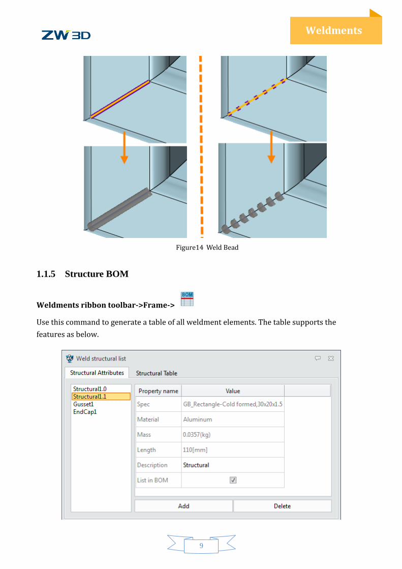
1.1.5 Structure BOM
Weldments ribbon toolbar->Frame->
Use this command to generate a table of all weldment elements. The table supports the
features as below.

10
Weldments
Figure15 Structure BOM
If the option “Combine structural with same Spec and Material" is checked, the rows with same
attributes will be merged together.
Tips: How to show the Mass for structure member?
STEP 01 Set the material for all the structure member shapes.
STEP 02 Inquire the mass properties.

11
Weldments
1.2 Case---Weldment
In this module, you can learn how to use those weldment functions to design your own product.
The following case will show you the general process of weldment in ZW3D.
Through below example to, you will learn how to use Structure member, endcap, gusset,
structure BOM, etc.to create weldment part.
Figure16 Case- Table Support
1. Create the Frame sketch
STEP 01 In the Shape ribbon tab, select 3D sketch function. Then create a sketch like below.
Figure17 3D Sketch1

12
Weldments
2. Create Structure Member
STEP 01 Click Structure member command and select 4 lines, as shown in the image below.
STEP 02 Define the standard to ISO, and type to ISO_Square-Cold formed, set the size to
50x50x4. And select the corner treatment to end miter with default parameters.
Figure18 Structure Member
3. Create Table Supports
STEP 01 Middle click to repeat the last operation -Structural member.
STEP 02 Select 4 vertical lines and set the parameters which are the same with the last
operation.
Figure19 Supports
13
Weldments
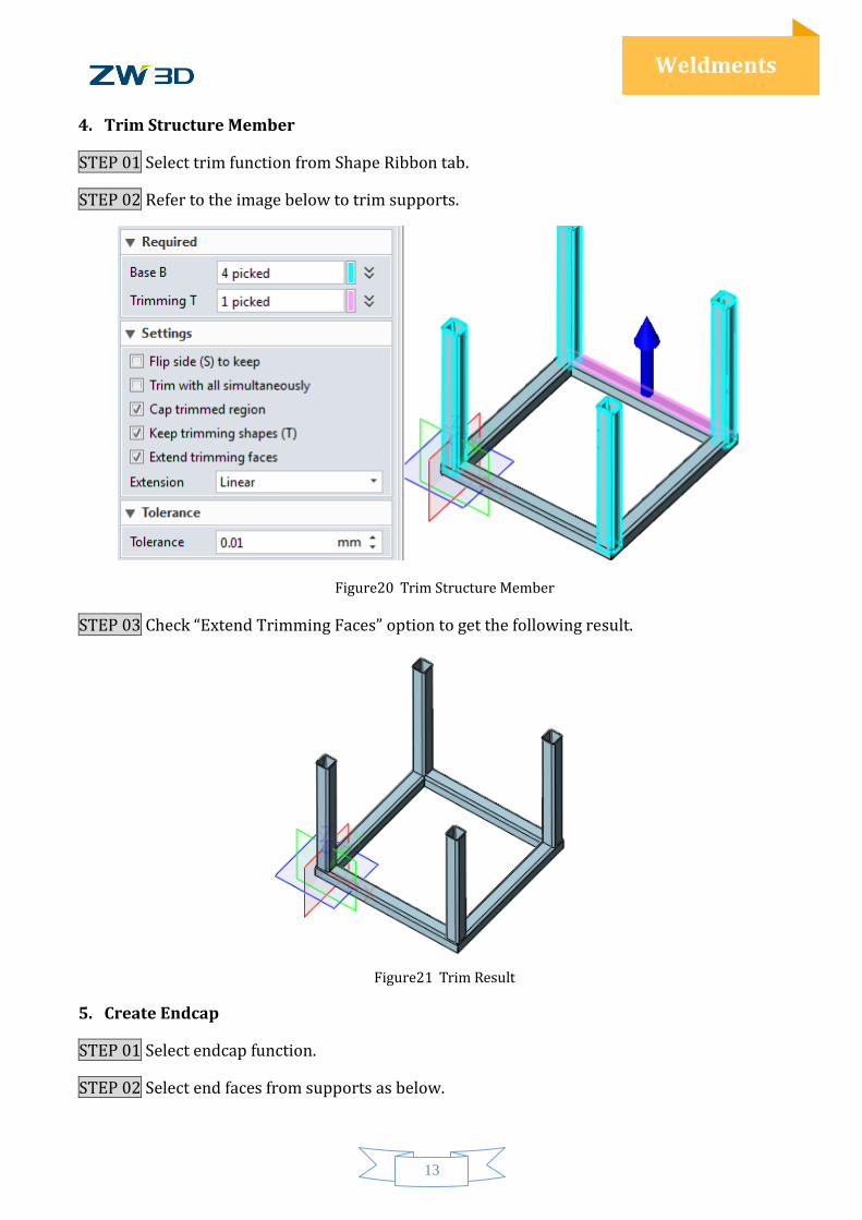
4. Trim Structure Member
STEP 01 Select trim function from Shape Ribbon tab.
STEP 02 Refer to the image below to trim supports.
Figure20 Trim Structure Member
STEP 03 Check “Extend Trimming Faces” option to get the following result.
Figure21 Trim Result
5. Create Endcap
STEP 01 Select endcap function.
STEP 02 Select end faces from supports as below.

14
Weldments
STEP 03 Check “Reverse” option and set the distance value to 10.
Figure22 Endcap
6. Create Weld Bead
STEP 01 Select weld bead function.
STEP 02 Select loop curves like below.
STEP 03 Set the radius to 1 and keep other parameters in default.
Figure23 Weld Bead
Use the same method to create the other three weld beads.
7. Create Gusset
STEP 01 Select gusset function.
STEP 02 Select the cross faces, and set the type to triangular, and set d1 & d2 to 50.

15
Weldments
Figure24 Gusset
Then we can use the same method to create other 3 gussets. The final model is shown in the
following image.
Figure25 Result