Embed Size (px)
Citation preview

7/22/2019 weldinginspectioncswip-100402035204-phpapp02
http://slidepdf.com/reader/full/weldinginspectioncswip-100402035204-phpapp02 1/636
Welding Inspector
4/23/2007 1 of 691
Duties and Responsib i l i t ies
Sec t ion 1

7/22/2019 weldinginspectioncswip-100402035204-phpapp02
http://slidepdf.com/reader/full/weldinginspectioncswip-100402035204-phpapp02 2/636

7/22/2019 weldinginspectioncswip-100402035204-phpapp02
http://slidepdf.com/reader/full/weldinginspectioncswip-100402035204-phpapp02 3/636
Personal Attributes 1.1
Important qualities that good Inspectors are expected to have
are:•Honesty
•Integrity
•Knowledge
•Good communicator
•Physical fitness
•Good eyesight
4/23/2007 3 of 691

7/22/2019 weldinginspectioncswip-100402035204-phpapp02
http://slidepdf.com/reader/full/weldinginspectioncswip-100402035204-phpapp02 4/636
Standard for Visual Inspection 1.1
Basic Requirements
4/23/2007 4 of 691
BS EN 970 - Non-destructive examination of fusion
welds - Visual examination
Welding Inspection Personnel should:
• be familiar with relevant standards, rules and specifications
applicable to the fabrication work to be undertaken
• be informed about the welding procedures to be used
• have good vision (which shou ld be checked every 12
months)
7/22/2019 weldinginspectioncswip-100402035204-phpapp02
http://slidepdf.com/reader/full/weldinginspectioncswip-100402035204-phpapp02 5/636

7/22/2019 weldinginspectioncswip-100402035204-phpapp02
http://slidepdf.com/reader/full/weldinginspectioncswip-100402035204-phpapp02 6/636
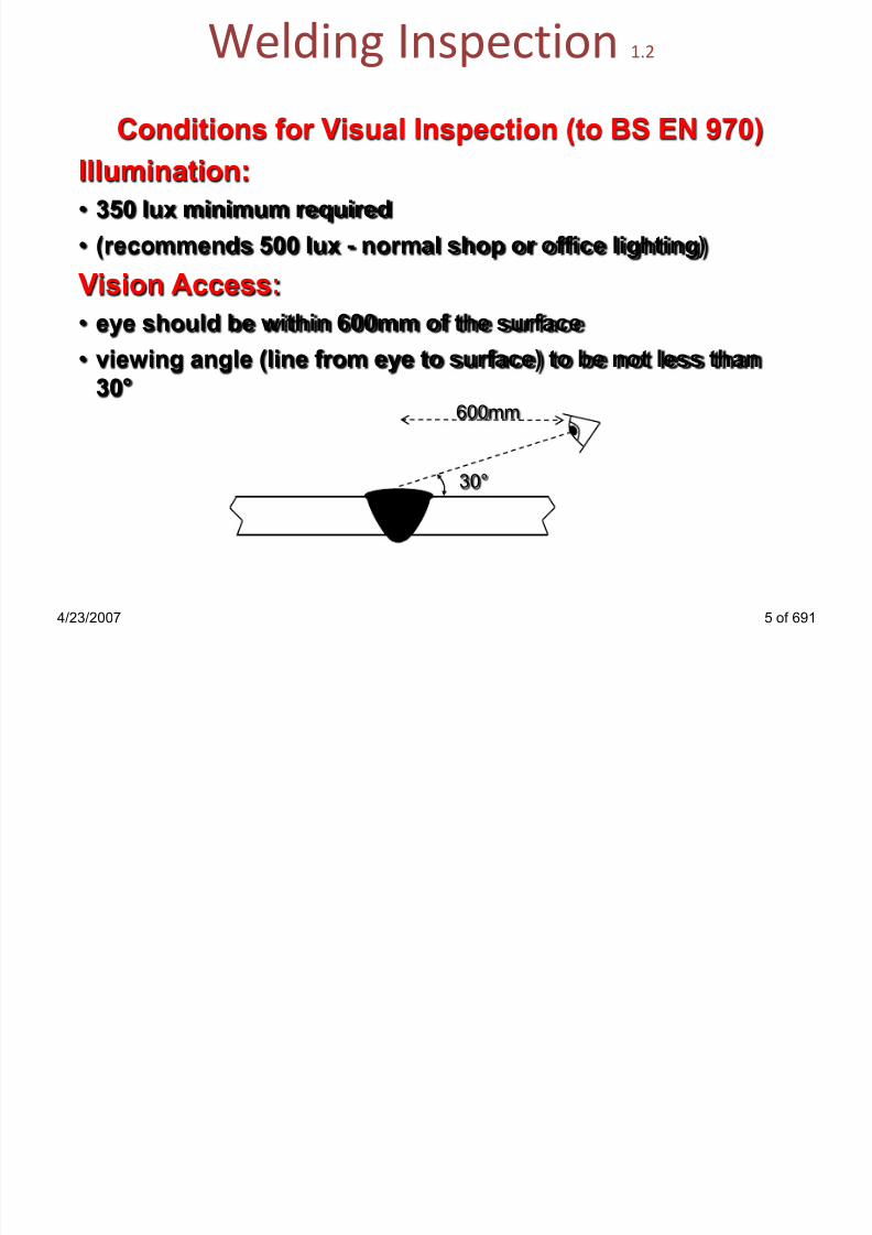
Welding Inspection 1.3
Aids to Visual Inspection (to BS EN 970)
When access is restricted may use:• a mirrored boroscope• a fibre optic viewing system
Other aids:• welding gauges (for checking bevel angles, weld profile, fillet
sizing, undercut depth)• dedicated weld-gap gauges and linear misalignment (high-low)
gauges
• straight edges and measuring tapes• magnifying lens (if magnification lens used it should have
magnification between X2 to X5)
4/23/2007 6 of 691
usually by
agreement
}

7/22/2019 weldinginspectioncswip-100402035204-phpapp02
http://slidepdf.com/reader/full/weldinginspectioncswip-100402035204-phpapp02 7/636

7/22/2019 weldinginspectioncswip-100402035204-phpapp02
http://slidepdf.com/reader/full/weldinginspectioncswip-100402035204-phpapp02 8/636
Welding Inspectors Gauges 1.3
4/23/2007 8 of 691
TWI Multi-purpose Welding Gauge Misalignment Gauges
Hi-Lo Gauge
Fillet Weld Gauges
G.A.L.
S.T.D.
10mm
16mm
L
G.A.L.
S.T.D.
10mm
16mm
01/4 1/2 3/4
IN
H
I - L O
S i n g l e P u r p o s e W e l d i n g
G a u g e
1
2
3
4
5
6

7/22/2019 weldinginspectioncswip-100402035204-phpapp02
http://slidepdf.com/reader/full/weldinginspectioncswip-100402035204-phpapp02 9/636
Welding Inspectors Equipment 1.3
4/23/2007 9 of 691
Tong Tester
Ammeter Voltmeter

7/22/2019 weldinginspectioncswip-100402035204-phpapp02
http://slidepdf.com/reader/full/weldinginspectioncswip-100402035204-phpapp02 10/636
Welding Inspection 1.3
4/23/2007 10 of 691
Stages of Visual Inspection (to BS EN 970)Extent of examination and when required should be defined in
the application standard or by agreement between the
contracting parties
For high integrity fabrications inspection required throughout
the fabrication process:
Before welding
(Before assemble & After assembly)
During welding
After welding

7/22/2019 weldinginspectioncswip-100402035204-phpapp02
http://slidepdf.com/reader/full/weldinginspectioncswip-100402035204-phpapp02 11/636
Typical Duties of a Welding Inspector 1.5
4/23/2007 11 of 691
Before Welding
Preparation:
Familiarisation with relevant „documents‟…
• Application Standard/Code - for visual acceptance
requirements
• Drawings - item details and positions/tolerances etc
• Quality Control Procedures - for activities such as material
handling, documentation control, storage & issue of
welding consumables
• Quality Plan/Inspection & Test Plan/Inspection Checklist -
details of inspection requirements, inspection procedures
& records required

7/22/2019 weldinginspectioncswip-100402035204-phpapp02
http://slidepdf.com/reader/full/weldinginspectioncswip-100402035204-phpapp02 12/636
Typical Duties of a Welding Inspector 1.5
4/23/2007 12 of 691
Before WeldingWelding Procedures:
• are applicable to joints to be welded & approved
• are available to welders & inspectors
Welder Qualifications:
• list of available qualified welders related to WPS‟s
• certificates are valid and ‘in- date’

7/22/2019 weldinginspectioncswip-100402035204-phpapp02
http://slidepdf.com/reader/full/weldinginspectioncswip-100402035204-phpapp02 13/636
Typical Duties of a Welding Inspector 1.5
Before Welding
Equipment:• all inspection equipment is in good condition & calibrated as
necessary
• all safety requirements are understood & necessary equipment
availableMaterials:
• can be identified & related to test certificates, traceability !
• are of correct dimensions
• are in suitable condition (no damage/contamination)
4/23/2007 13 of 691

7/22/2019 weldinginspectioncswip-100402035204-phpapp02
http://slidepdf.com/reader/full/weldinginspectioncswip-100402035204-phpapp02 14/636
Typical Duties of a Welding Inspector 1.5
Before Welding
Consumables:
• in accordance with WPS’s
• are being controlled in accordance with Procedure
Weld Preparations:
• comply with WPS/drawing
• free from defects & contamination
Welding Equipment:
• in good order & calibrated as required by Procedure
4/23/2007 14 of 691

7/22/2019 weldinginspectioncswip-100402035204-phpapp02
http://slidepdf.com/reader/full/weldinginspectioncswip-100402035204-phpapp02 15/636
Typical Duties of a Welding Inspector 1.5
Before Welding
Fit-up
• complies with WPS
• Number / size of tack welds to Code / goodworkmanship
Pre-heat
• if specified• minimum temperature complies with WPS
4/23/2007 15 of 691

7/22/2019 weldinginspectioncswip-100402035204-phpapp02
http://slidepdf.com/reader/full/weldinginspectioncswip-100402035204-phpapp02 16/636
Typical Duties of a Welding Inspector 1.5
4/23/2007 16 of 691
During Welding
Weather conditions
• suitable if site / field welding
Welding Process(es)
• in accordance with WPS
Welder
• is approved to weld the joint
Pre-heat (if required)
• minimum temperature as specified by WPS
• maximum interpass temperature as WPS

7/22/2019 weldinginspectioncswip-100402035204-phpapp02
http://slidepdf.com/reader/full/weldinginspectioncswip-100402035204-phpapp02 17/636
Typical Duties of a Welding Inspector 1.6
During Welding
Welding consumables
• in accordance with WPS
• in suitable condition
• controlled issue and handling
Welding Parameters
• current, voltage & travel speed – as WPS
Root runs
• if possible, visually inspect root before single-sided welds arefilled up
4/23/2007 17 of 691

7/22/2019 weldinginspectioncswip-100402035204-phpapp02
http://slidepdf.com/reader/full/weldinginspectioncswip-100402035204-phpapp02 18/636
Typical Duties of a Welding Inspector 1.6
During Welding
Inter-run cleaning
in accordance with an approved method (& back gouging) to
good workmanship standard
Distortion control
• welding is balanced & over-welding is avoided
4/23/2007 18 of 691

7/22/2019 weldinginspectioncswip-100402035204-phpapp02
http://slidepdf.com/reader/full/weldinginspectioncswip-100402035204-phpapp02 19/636
Typical Duties of a Welding Inspector 1.6
4/23/2007 19 of 691
After Welding
Weld Identification
• identified/numbered as required
• is marked with welder‟s identity
Visual Inspection
• ensure weld is suitable for all NDT
• visually inspect & „sentence‟ to Code requirements
Dimensional Survey
• ensure dimensions comply with Code/drawing
Other NDT
• ensure all NDT is completed & reports available

7/22/2019 weldinginspectioncswip-100402035204-phpapp02
http://slidepdf.com/reader/full/weldinginspectioncswip-100402035204-phpapp02 20/636
Typical Duties of a Welding Inspector 1.6
After Welding
Repairs• monitor repairs to ensure compliance with Procedure, ensure
NDT after repairs is completed
• PWHT
• monitor for compliance with Procedure
• check chart records confirm Procedure compliance
Pressure / Load Test
• ensure test equipment is suitably calibrated
• monitor to ensure compliance with Procedure• ensure all records are available
4/23/2007 20 of 691

7/22/2019 weldinginspectioncswip-100402035204-phpapp02
http://slidepdf.com/reader/full/weldinginspectioncswip-100402035204-phpapp02 21/636
Typical Duties of a Welding Inspector 1.6
After WeldingDocumentation
• ensure any modifications are on ‘as-built’ drawings
• ensure all required documents are available
• Collate / file documents for manufacturing records
• Sign all documentation and forward it to QC department.
4/23/2007 21 of 691

7/22/2019 weldinginspectioncswip-100402035204-phpapp02
http://slidepdf.com/reader/full/weldinginspectioncswip-100402035204-phpapp02 22/636
Summary of Duties
A Welding Inspector must:
• Observe
To observe all relevant actions related to weld quality throughout
production.
• Record
To record, or log all production inspection points relevant to quality,
including a final report showing all identified imperfections
• CompareTo compare all recorded information with the acceptance criteria
and any other relevant clauses in the applied application standard
4/23/2007 22 of 691
It is the duty of a Welding Inspector to ensure all the welding and
associated actions are carried out in accordance with the
specification and any applicable procedures.

7/22/2019 weldinginspectioncswip-100402035204-phpapp02
http://slidepdf.com/reader/full/weldinginspectioncswip-100402035204-phpapp02 23/636

7/22/2019 weldinginspectioncswip-100402035204-phpapp02
http://slidepdf.com/reader/full/weldinginspectioncswip-100402035204-phpapp02 24/636
Welding Terminology & Definitions 2.1
4/23/2007 24 of 691
What is a Weld?• A localised coalescence of metals or non-metals produced
either by heating the materials to the welding temperature,
with or without the application of pressure, or by the
application of pressure alone (AWS)
• A permanent union between materials caused by heat, and
or pressure (BS499)
• An Autogenous weld:
A weld made with out the use of a filler material and canonly be made by TIG or Oxy-Gas Welding
7/22/2019 weldinginspectioncswip-100402035204-phpapp02
http://slidepdf.com/reader/full/weldinginspectioncswip-100402035204-phpapp02 25/636
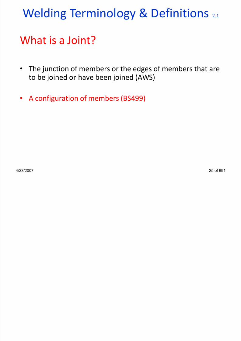
Welding Terminology & Definitions 2.1
What is a Joint?
• The junction of members or the edges of members that areto be joined or have been joined (AWS)
• A configuration of members (BS499)
4/23/2007 25 of 691

7/22/2019 weldinginspectioncswip-100402035204-phpapp02
http://slidepdf.com/reader/full/weldinginspectioncswip-100402035204-phpapp02 26/636
Joint Terminology 2.2
4/23/2007 26 of 691
Edge Open & Closed Corner Lap
Tee ButtCruciform

7/22/2019 weldinginspectioncswip-100402035204-phpapp02
http://slidepdf.com/reader/full/weldinginspectioncswip-100402035204-phpapp02 27/636
Welded Butt Joints 2.2
4/23/2007 27 of 691
A_________Welded butt jointButt
A_________Welded butt jointFillet
A____________Welded butt jointCompound

7/22/2019 weldinginspectioncswip-100402035204-phpapp02
http://slidepdf.com/reader/full/weldinginspectioncswip-100402035204-phpapp02 28/636

7/22/2019 weldinginspectioncswip-100402035204-phpapp02
http://slidepdf.com/reader/full/weldinginspectioncswip-100402035204-phpapp02 29/636
Weld Terminology 2.3
4/23/2007 29 of 691
Compound weld
Fillet weldButt weld
Edge weld
Spot weld
Plug weld
B tt P ti Si

7/22/2019 weldinginspectioncswip-100402035204-phpapp02
http://slidepdf.com/reader/full/weldinginspectioncswip-100402035204-phpapp02 30/636
Butt Preparations – Sizes 2.4
4/23/2007 30 of 691
Full Penetration Butt Weld
Partial Penetration Butt Weld
Design Throat
Thickness
Design Throat
Thickness
Actual Throat
Thickness
Actual Throat
Thickness

7/22/2019 weldinginspectioncswip-100402035204-phpapp02
http://slidepdf.com/reader/full/weldinginspectioncswip-100402035204-phpapp02 31/636
4/23/2007 31 of 691
Weld Zone Terminology 2.5
WeldBoundary
C
A B
D
HeatAffectedZone
Root
Weldmetal
A, B, C & D = Weld Toes
Face

7/22/2019 weldinginspectioncswip-100402035204-phpapp02
http://slidepdf.com/reader/full/weldinginspectioncswip-100402035204-phpapp02 32/636
H Aff d Z (HAZ)

7/22/2019 weldinginspectioncswip-100402035204-phpapp02
http://slidepdf.com/reader/full/weldinginspectioncswip-100402035204-phpapp02 33/636
Heat Affected Zone (HAZ) 2.5
4/23/2007 33 of 691
tempered zone
grain growth zone
recrystallised zone
partially transformed zone
Maximum
Temperature
solid-liquid Boundarysolid
weld
metal
unaffected base
material

7/22/2019 weldinginspectioncswip-100402035204-phpapp02
http://slidepdf.com/reader/full/weldinginspectioncswip-100402035204-phpapp02 34/636
Joint Preparation Terminology 2.7
4/23/2007 34 of 691
Included angle
Root GapRoot Face
Angle of
bevel
Root FaceRoot Gap
Included angle
RootRadius
Single-V Butt Single-U Butt
J i t P ti T i l

7/22/2019 weldinginspectioncswip-100402035204-phpapp02
http://slidepdf.com/reader/full/weldinginspectioncswip-100402035204-phpapp02 35/636
Joint Preparation Terminology 2.8 & 2.9
4/23/2007 35 of 691
Root Gap
Root Face Root FaceRoot Gap
Root
Radius
Single Bevel Butt Single-J Butt
Angle of bevel Angle of bevel
Land
Si l Sid d B P i

7/22/2019 weldinginspectioncswip-100402035204-phpapp02
http://slidepdf.com/reader/full/weldinginspectioncswip-100402035204-phpapp02 36/636
Single Sided Butt Preparations 2.10
4/23/2007 36 of 691
Single Bevel Single Vee
Single-J Single-U
Single sided preparations are normally made on thinner materials, or
when access form both sides is restricted

7/22/2019 weldinginspectioncswip-100402035204-phpapp02
http://slidepdf.com/reader/full/weldinginspectioncswip-100402035204-phpapp02 37/636

7/22/2019 weldinginspectioncswip-100402035204-phpapp02
http://slidepdf.com/reader/full/weldinginspectioncswip-100402035204-phpapp02 38/636

7/22/2019 weldinginspectioncswip-100402035204-phpapp02
http://slidepdf.com/reader/full/weldinginspectioncswip-100402035204-phpapp02 39/636

7/22/2019 weldinginspectioncswip-100402035204-phpapp02
http://slidepdf.com/reader/full/weldinginspectioncswip-100402035204-phpapp02 40/636
Fillet Weld Features 2.13
4/23/2007 40 of 691
Design
Throat
Vertical
Leg
Length
Horizontal leg
Length
Excess
Weld
Metal
Fill t W ld Th t Thi k

7/22/2019 weldinginspectioncswip-100402035204-phpapp02
http://slidepdf.com/reader/full/weldinginspectioncswip-100402035204-phpapp02 41/636
Fillet Weld Throat Thickness 2.13
4/23/2007 41 of 691
b
a
b = Actual Throat Thickness
a = Design Throat Thickness
Deep Penetration Fillet Weld Features

7/22/2019 weldinginspectioncswip-100402035204-phpapp02
http://slidepdf.com/reader/full/weldinginspectioncswip-100402035204-phpapp02 42/636
Deep Penetration Fillet Weld Features 2.13
4/23/2007 42 of 691
b
a
b = Actual Throat Thickness
a = Design Throat Thickness
Fillet Weld Sizes
7/22/2019 weldinginspectioncswip-100402035204-phpapp02
http://slidepdf.com/reader/full/weldinginspectioncswip-100402035204-phpapp02 43/636
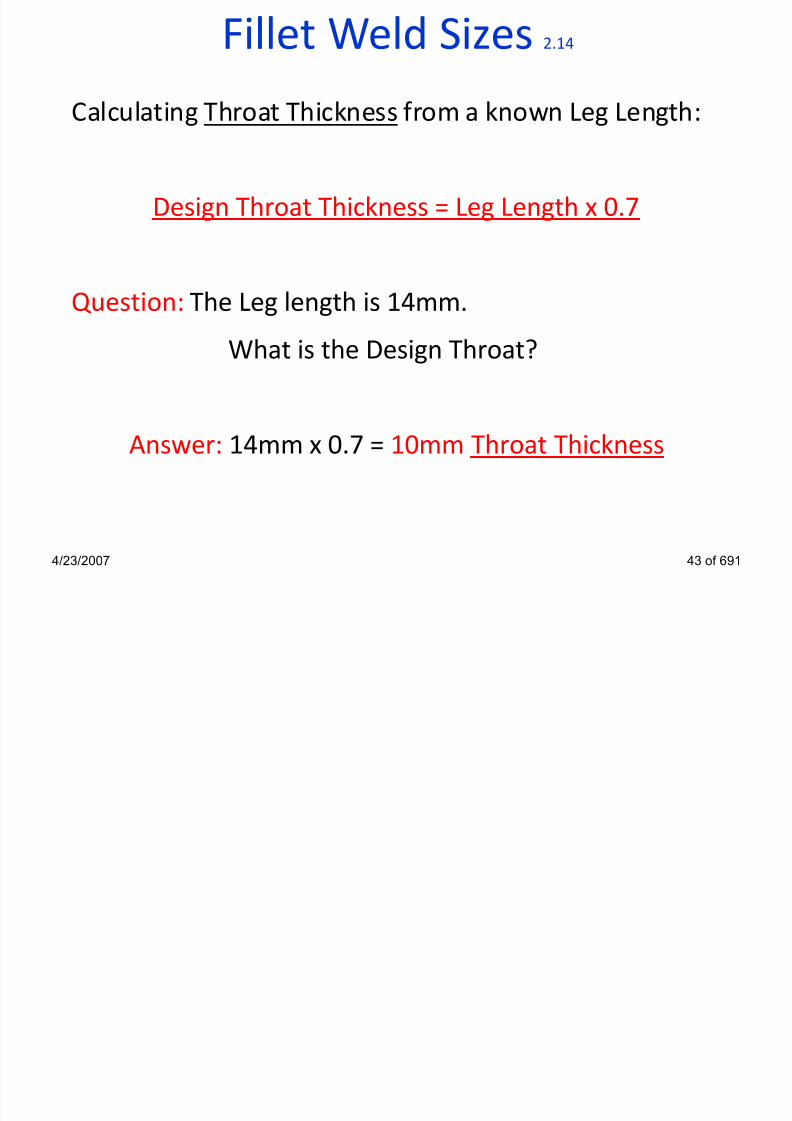
Fillet Weld Sizes 2.14
Calculating Throat Thickness from a known Leg Length:
Design Throat Thickness = Leg Length x 0.7
Question: The Leg length is 14mm.
What is the Design Throat?
Answer: 14mm x 0.7 = 10mm Throat Thickness
4/23/2007 43 of 691
Fillet Weld Sizes

7/22/2019 weldinginspectioncswip-100402035204-phpapp02
http://slidepdf.com/reader/full/weldinginspectioncswip-100402035204-phpapp02 44/636
Fillet Weld Sizes 2.14
Calculating Leg Length from a known Design Throat
Thickness:
Leg Length = Design Throat Thickness x 1.4
Question: The Design Throat is 10mm.
What is the Leg length?
Answer: 10mm x 1.4 = 14mm Leg Length
4/23/2007 44 of 691
Features to Consider 2

7/22/2019 weldinginspectioncswip-100402035204-phpapp02
http://slidepdf.com/reader/full/weldinginspectioncswip-100402035204-phpapp02 45/636
Features to Consider 2 2.14
Importance of Fillet Weld Leg Length Size
4/23/2007 45 of 691
Approximately the same weld volume in both Fillet
Welds, but the effective throat thickness has been
altered, reducing considerably the strength of weld B
2mm
(b)
4mm
8mm
(a)
4mm
Fillet Weld Sizes

7/22/2019 weldinginspectioncswip-100402035204-phpapp02
http://slidepdf.com/reader/full/weldinginspectioncswip-100402035204-phpapp02 46/636
Fillet Weld Sizes 2.14
Importance of Fillet weld leg length Size
4/23/2007 46 of 691
Area = 4 x 4 =
8mm2
2
Area = 6 x 6 =
18mm2
2
The c.s.a. of (b) is over double the area of (a) without the extra
excess weld metal being added
4mm 6mm
(a) (b)
4mm 6mm
(a) (b)
Excess
Excess

7/22/2019 weldinginspectioncswip-100402035204-phpapp02
http://slidepdf.com/reader/full/weldinginspectioncswip-100402035204-phpapp02 47/636

7/22/2019 weldinginspectioncswip-100402035204-phpapp02
http://slidepdf.com/reader/full/weldinginspectioncswip-100402035204-phpapp02 48/636
ldi i i

7/22/2019 weldinginspectioncswip-100402035204-phpapp02
http://slidepdf.com/reader/full/weldinginspectioncswip-100402035204-phpapp02 49/636
Welding Positions 2.17
PA 1G / 1F Flat / Downhand
PB 2F Horizontal-Vertical
PC 2G Horizontal
PD 4F Horizontal-Vertical (Overhead)
PE 4G Overhead
PF 3G / 5G Vertical-Up
PG 3G / 5G Vertical-Down
H-L045 6G Inclined Pipe (Upwards)
J-L045 6G Inclined Pipe (Downwards)
4/23/2007 49 of 691

7/22/2019 weldinginspectioncswip-100402035204-phpapp02
http://slidepdf.com/reader/full/weldinginspectioncswip-100402035204-phpapp02 50/636
Welding position designation 2 17

7/22/2019 weldinginspectioncswip-100402035204-phpapp02
http://slidepdf.com/reader/full/weldinginspectioncswip-100402035204-phpapp02 51/636
Welding position designation 2.17
Butt welds in plate (see ISO 6947)
4/23/2007 51 of 691
Flat - PA Overhead - PE
Vertical
up - PF
Vertical
down - PG
Horizontal - PC
Welding position designation 2 17

7/22/2019 weldinginspectioncswip-100402035204-phpapp02
http://slidepdf.com/reader/full/weldinginspectioncswip-100402035204-phpapp02 52/636
Welding position designation 2.17
Butt welds in pipe (see ISO 6947)
4/23/2007 52 of 691
Flat - PA
axis: horizontalpipe: rotated
H-L045
axis: inclined at 45°
pipe: fixed
Horizontal - PC
axis: vertical
pipe: fixed
Vertical up - PF
axis: horizontal
pipe: fixed
Vertical down - PG
axis: horizontal
pipe: fixed
J-L045
axis: inclined at 45°
pipe: fixed
Welding position designation 2 17

7/22/2019 weldinginspectioncswip-100402035204-phpapp02
http://slidepdf.com/reader/full/weldinginspectioncswip-100402035204-phpapp02 53/636
Welding position designation 2.17
Fillet welds on plate (see ISO 6947)
4/23/2007 53 of 691
Flat - PA Overhead - PD
Vertical up - PF Vertical down - PG
Horizontal - PB
Welding position designation 2 17

7/22/2019 weldinginspectioncswip-100402035204-phpapp02
http://slidepdf.com/reader/full/weldinginspectioncswip-100402035204-phpapp02 54/636
Welding position designation 2.17
Fillet welds on pipe (see ISO 6947)
4/23/2007 54 of 691
Flat - PAaxis: inclined at 45°
pipe: rotated
Overhead - PDaxis: vertical
pipe: fixed
Vertical up - PFaxis: horizontal
pipe: fixed
Vertical down - PGaxis: horizontal
pipe: fixed
Horizontal - PBaxis: vertical
pipe: fixed
Horizontal - PBaxis: horizontal
pipe: rotated
Plate/Fillet Weld Positions

7/22/2019 weldinginspectioncswip-100402035204-phpapp02
http://slidepdf.com/reader/full/weldinginspectioncswip-100402035204-phpapp02 55/636
4/23/2007 55 of 691
Plate/Fillet Weld Positions 2.17
PA / 1GPA / 1F
PC / 2GPB / 2F
PD / 4FPE / 4G PG / 3G
PF / 3G
Pipe Welding Positions 2 17
7/22/2019 weldinginspectioncswip-100402035204-phpapp02
http://slidepdf.com/reader/full/weldinginspectioncswip-100402035204-phpapp02 56/636
4/23/2007 56 of 691
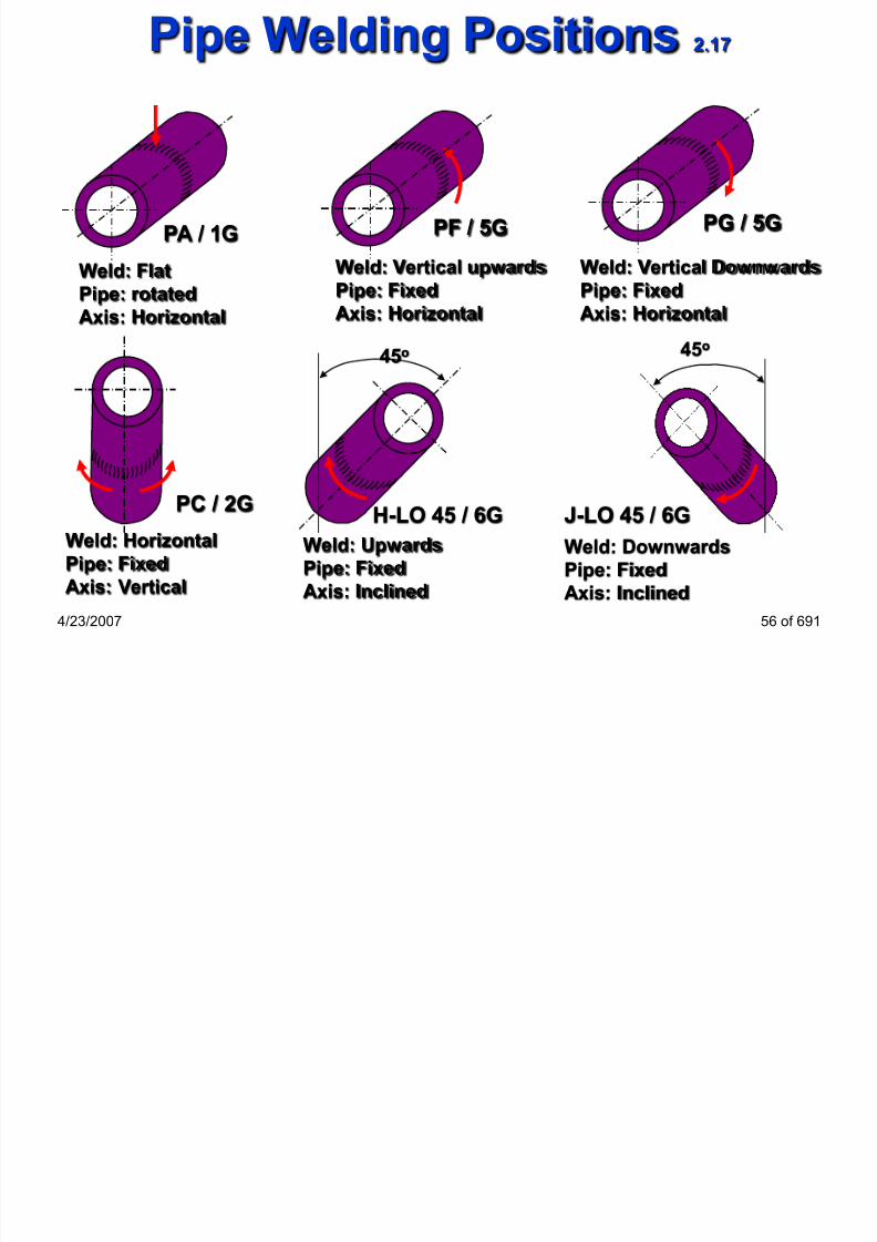
Pipe Welding Positions 2.17
Weld: Flat
Pipe: rotated
Axis: Horizontal
PA / 1G
Weld: Vertical Downwards
Pipe: Fixed
Axis: Horizontal
PG / 5G
Weld: Vertical upwards
Pipe: Fixed
Axis: Horizontal
PF / 5G
Weld: Upwards
Pipe: Fixed
Axis: Inclined
Weld: Horizontal
Pipe: Fixed
Axis: Vertical
PC / 2G
45o
Weld: Downwards
Pipe: Fixed
Axis: Inclined
J-LO 45 / 6G
45o
H-LO 45 / 6G
Travel Speed Measurement

7/22/2019 weldinginspectioncswip-100402035204-phpapp02
http://slidepdf.com/reader/full/weldinginspectioncswip-100402035204-phpapp02 57/636
Travel Speed Measurement 2.18
4/23/2007 57 of 691
Definition: the rate of weld progression
measured in case of mechanised and automaticwelding processes
in case of MMA can be determined using ROL and arc
time

7/22/2019 weldinginspectioncswip-100402035204-phpapp02
http://slidepdf.com/reader/full/weldinginspectioncswip-100402035204-phpapp02 58/636
Welding Inspector
Welding Imperfections
Section 3
4/23/2007 58 of 691
Welding Imperfections

7/22/2019 weldinginspectioncswip-100402035204-phpapp02
http://slidepdf.com/reader/full/weldinginspectioncswip-100402035204-phpapp02 59/636
Welding Imperfections 3.1
4/23/2007 59 of 691
All welds have imperfections
• Imperfections are classed as defects when they are of a
type, or size, not allowed by the Acceptance Standard
A defect is an unacceptable imperfection
• A weld imperfection may be allowed by one Acceptance
Standard but be classed as a defect by another Standard
and require removal/rectification
Welding Imperfections

7/22/2019 weldinginspectioncswip-100402035204-phpapp02
http://slidepdf.com/reader/full/weldinginspectioncswip-100402035204-phpapp02 60/636
Welding Imperfections 3.1
4/23/2007 60 of 691
Standards for Welding Imperfections
BS EN ISO 6520-1(1998) Welding and allied processes –
Classification of geometric
imperfections in metallic materials -
Part 1: Fusion welding
Imperfections are classified into 6 groups, namely:
1 Cracks
2 Cavities
3 Solid inclusions
4 Lack of fusion and penetration
5 Imperfect shape and dimensions
6 Miscellaneous imperfections
Welding Imperfections

7/22/2019 weldinginspectioncswip-100402035204-phpapp02
http://slidepdf.com/reader/full/weldinginspectioncswip-100402035204-phpapp02 61/636
Welding Imperfections 3.1
4/23/2007 61 of 691
Standards for Welding Imperfections
EN ISO 5817 (2003) Welding - Fusion-welded joints in steel,
nickel, titanium and their alloys (beam
welding excluded) - Quality levels for
imperfections
This main imperfections given in EN ISO 6520-1 are listed inEN ISO 5817 with acceptance criteria at 3 levels, namely
Level B (highest)
Level C (intermediate)
Level D (general)
This Standard is „directly applicable to visual testing of welds‟
...(weld surfaces & macro exam inat ion)
Welding imperfections

7/22/2019 weldinginspectioncswip-100402035204-phpapp02
http://slidepdf.com/reader/full/weldinginspectioncswip-100402035204-phpapp02 62/636
Welding imperfections 3.1
classification
Cracks
4/23/2007 62 of 691

7/22/2019 weldinginspectioncswip-100402035204-phpapp02
http://slidepdf.com/reader/full/weldinginspectioncswip-100402035204-phpapp02 63/636
Cracks

7/22/2019 weldinginspectioncswip-100402035204-phpapp02
http://slidepdf.com/reader/full/weldinginspectioncswip-100402035204-phpapp02 64/636
Cracks 3.1
4/23/2007 64 of 691
Longitudinal parent metal
Longitudinal weld metal
Lamellar tearing
Transverse weld metal

7/22/2019 weldinginspectioncswip-100402035204-phpapp02
http://slidepdf.com/reader/full/weldinginspectioncswip-100402035204-phpapp02 65/636
Cracks

7/22/2019 weldinginspectioncswip-100402035204-phpapp02
http://slidepdf.com/reader/full/weldinginspectioncswip-100402035204-phpapp02 66/636
Cracks 3.2
Main Crack Types
• Solidification Cracks
• Hydrogen Induced Cracks
• Lamellar Tearing
• Reheat cracks
4/23/2007 66 of 691
Cracks
7/22/2019 weldinginspectioncswip-100402035204-phpapp02
http://slidepdf.com/reader/full/weldinginspectioncswip-100402035204-phpapp02 67/636
Cracks 3.2
Solidification Cracking
• Occurs during weld solidification process
• Steels with high sulphur impurities content (low ductility
at elevated temperature)
• Requires high tensile stress
• Occur longitudinally down centre of weld
4/23/2007 67 of 691
Cracks 3.3

7/22/2019 weldinginspectioncswip-100402035204-phpapp02
http://slidepdf.com/reader/full/weldinginspectioncswip-100402035204-phpapp02 68/636
Hydrogen Induced Cold Cracking
• Requires susceptible hard grain structure, stress, low
temperature and hydrogen
• Hydrogen enters weld via welding arc mainly as result of
contaminated electrode or preparation
• Hydrogen diffuses out into parent metal on cooling
• Cracking developing most likely in HAZ
4/23/2007 68 of 691
Lamellar Tearing 3.5

7/22/2019 weldinginspectioncswip-100402035204-phpapp02
http://slidepdf.com/reader/full/weldinginspectioncswip-100402035204-phpapp02 69/636
g• Location: Parent metal
• Steel Type: Any steel type possible
• Susceptible Microstructure: Poor through thickness ductility
• Lamellar tearing has a step like appearance due to the solidinclusions in the parent material (e.g. sulphides and
silicates) linking up under the influence of welding stresses
• Low ductile materials in the short transverse directioncontaining high levels of impurities are very susceptible tolamellar tearing
• It forms when the welding stresses act in the shorttransverse direction of the material (through thicknessdirection)
4/23/2007 69 of 691
Gas Cavities

7/22/2019 weldinginspectioncswip-100402035204-phpapp02
http://slidepdf.com/reader/full/weldinginspectioncswip-100402035204-phpapp02 70/636
Gas Cavities 3.6
4/23/2007 70 of 691
Root piping
Cluster porosityGas pore
Blow hole
Herringbone porosity
Gas pore <1.5mm
Blow hole.>1.6mm
Causes:
•Loss of gas shield
•Damp electrodes
•Contamination
•Arc length too large•Damaged electrode flux
•Moisture on parent material
•Welding current too low

7/22/2019 weldinginspectioncswip-100402035204-phpapp02
http://slidepdf.com/reader/full/weldinginspectioncswip-100402035204-phpapp02 71/636
Gas Cavities 3.8

7/22/2019 weldinginspectioncswip-100402035204-phpapp02
http://slidepdf.com/reader/full/weldinginspectioncswip-100402035204-phpapp02 72/636
4/23/2007 72 of 691
Cluster porosity Herringbone porosity
Crater Pipe

7/22/2019 weldinginspectioncswip-100402035204-phpapp02
http://slidepdf.com/reader/full/weldinginspectioncswip-100402035204-phpapp02 73/636
4/23/2007 73 of 691
Crater pipe
Weld crater
Crater Pipe 3.9
Crater Pipe

7/22/2019 weldinginspectioncswip-100402035204-phpapp02
http://slidepdf.com/reader/full/weldinginspectioncswip-100402035204-phpapp02 74/636
4/23/2007 74 of 691
Crater pipe is a shrinkage defect and not a gas defect, it has
the appearance of a gas pore in the weld crater
Causes:
• Too fast a cooling
rate
• Deoxidization
reactions and
liquid to solid
volume change
• Contamination
Crater cracks
(Star cracks)
Crater pipe
Crater Pipe 3.9

7/22/2019 weldinginspectioncswip-100402035204-phpapp02
http://slidepdf.com/reader/full/weldinginspectioncswip-100402035204-phpapp02 75/636
Solid Inclusions

7/22/2019 weldinginspectioncswip-100402035204-phpapp02
http://slidepdf.com/reader/full/weldinginspectioncswip-100402035204-phpapp02 76/636
Solid Inclusions 3.11
4/23/2007 76 of 691
Elongated slag linesInterpass slag inclusions
Welding Imperfections 3.13

7/22/2019 weldinginspectioncswip-100402035204-phpapp02
http://slidepdf.com/reader/full/weldinginspectioncswip-100402035204-phpapp02 77/636
Welding Imperfections 3.13
4/23/2007 77 of 691
Typical Causes of Lack of Fusion:
• welding current too low
• bevel angle too steep
• root face too large (single-sided weld)
• root gap too small (single-sided weld)• incorrect electrode angle
• linear misalignment
• welding speed too high
• welding process related – particularly dip-transfer GMAW
• flooding the joint with too much weld metal (blocking Out)

7/22/2019 weldinginspectioncswip-100402035204-phpapp02
http://slidepdf.com/reader/full/weldinginspectioncswip-100402035204-phpapp02 78/636

7/22/2019 weldinginspectioncswip-100402035204-phpapp02
http://slidepdf.com/reader/full/weldinginspectioncswip-100402035204-phpapp02 79/636
Weld Root Imperfections 3.15

7/22/2019 weldinginspectioncswip-100402035204-phpapp02
http://slidepdf.com/reader/full/weldinginspectioncswip-100402035204-phpapp02 80/636
4/23/2007 80 of 691
Weld Root Imperfections 3.15
Lack of Root FusionLack of Root Penetration

7/22/2019 weldinginspectioncswip-100402035204-phpapp02
http://slidepdf.com/reader/full/weldinginspectioncswip-100402035204-phpapp02 81/636
Undercut 3 18

7/22/2019 weldinginspectioncswip-100402035204-phpapp02
http://slidepdf.com/reader/full/weldinginspectioncswip-100402035204-phpapp02 82/636
Undercut 3.18
4/23/2007 82 of 691
Cap undercutRoot undercut
Surface and Profile 3 19

7/22/2019 weldinginspectioncswip-100402035204-phpapp02
http://slidepdf.com/reader/full/weldinginspectioncswip-100402035204-phpapp02 83/636
Surface and Profile 3.19
4/23/2007 83 of 691
Incomplete filled groove Poor cap profile
Excessive cap height
Poor cap profiles and
excessive cap reinforcements
may lead to stress
concentration points at the
weld toes and will alsocontribute to overall poor toe
blend
Surface and Profile 3.19

7/22/2019 weldinginspectioncswip-100402035204-phpapp02
http://slidepdf.com/reader/full/weldinginspectioncswip-100402035204-phpapp02 84/636
Surface and Profile 3.19
4/23/2007 84 of 691
Incomplete filled grooveExcess cap reinforcement
Weld Root Imperfections 3 20
7/22/2019 weldinginspectioncswip-100402035204-phpapp02
http://slidepdf.com/reader/full/weldinginspectioncswip-100402035204-phpapp02 85/636
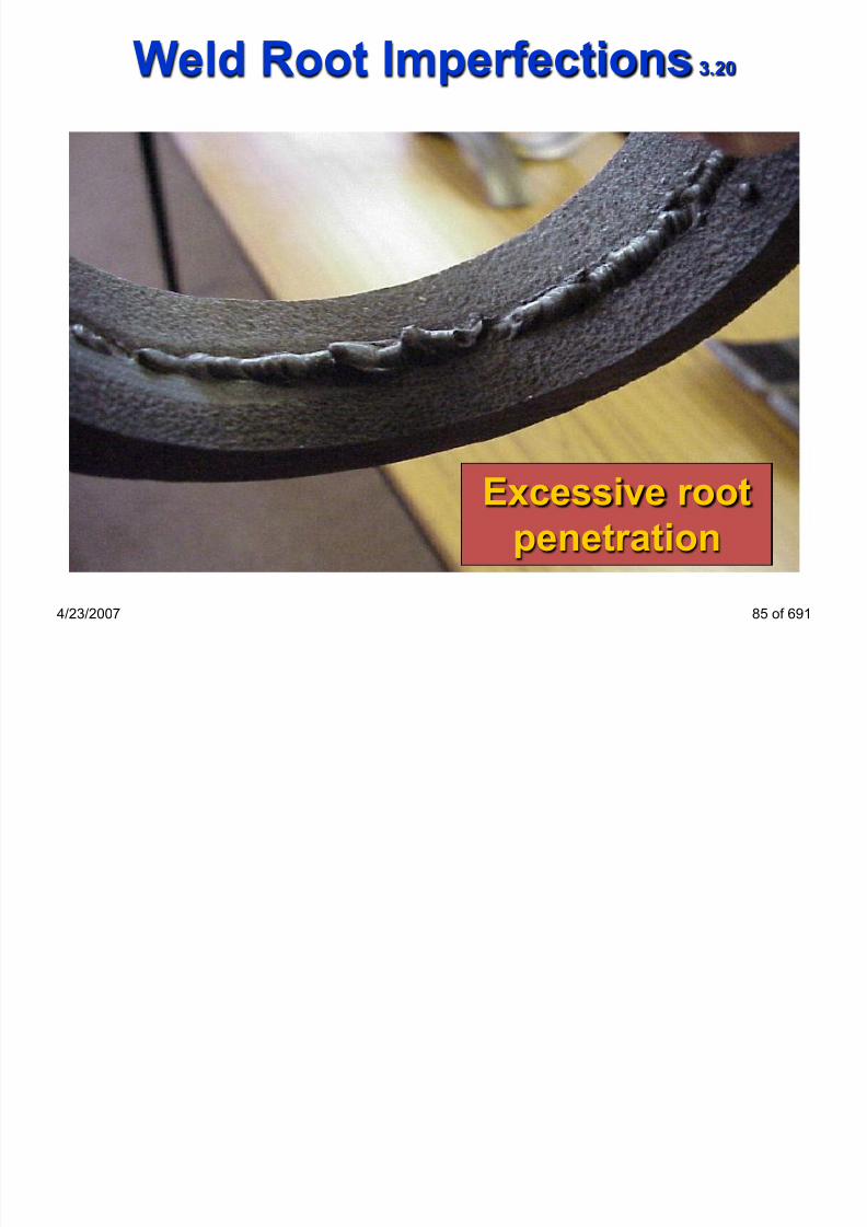
4/23/2007 85 of 691
Excessive root
penetration
Weld Root Imperfections 3.20
Overlap 3 21

7/22/2019 weldinginspectioncswip-100402035204-phpapp02
http://slidepdf.com/reader/full/weldinginspectioncswip-100402035204-phpapp02 86/636
Overlap 3.21
4/23/2007 86 of 691
An imperfection at the toe or root of a weld caused by metal
flowing on to the surface of the parent metal without fusing to it
Causes:
•Contamination
•Slow travel speed
•Incorrect welding
technique
•Current too low
Overlap 3 21

7/22/2019 weldinginspectioncswip-100402035204-phpapp02
http://slidepdf.com/reader/full/weldinginspectioncswip-100402035204-phpapp02 87/636
Overlap 3.21
4/23/2007 87 of 691
Toe Overlap
Toe Overlap
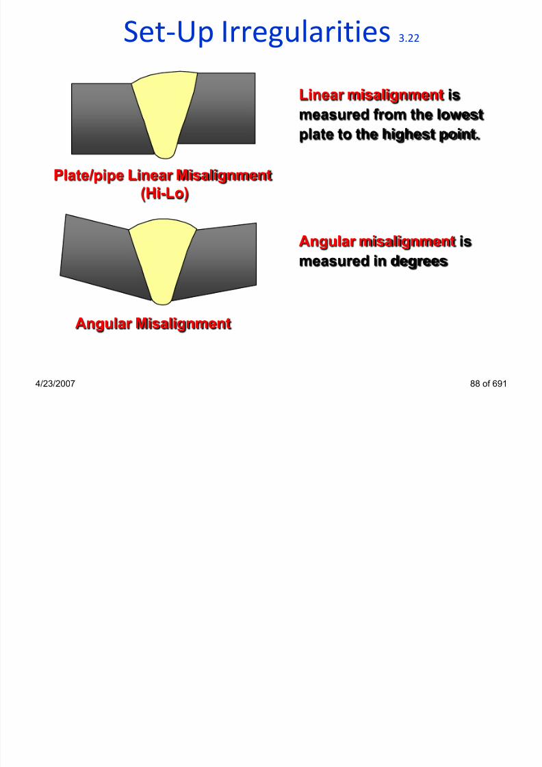
Set-Up Irregularities 3.22
7/22/2019 weldinginspectioncswip-100402035204-phpapp02
http://slidepdf.com/reader/full/weldinginspectioncswip-100402035204-phpapp02 88/636
p g
4/23/2007 88 of 691
Plate/pipe Linear Misalignment
(Hi-Lo)
Angular Misalignment
Linear misalignment is
measured from the lowest
plate to the highest point.
Angular misalignment is
measured in degrees
Set-Up Irregularities 3.22

7/22/2019 weldinginspectioncswip-100402035204-phpapp02
http://slidepdf.com/reader/full/weldinginspectioncswip-100402035204-phpapp02 89/636
Set Up Irregularities 3.22
4/23/2007 89 of 691
Linear Misalignment
Set-Up Irregularities 3.22

7/22/2019 weldinginspectioncswip-100402035204-phpapp02
http://slidepdf.com/reader/full/weldinginspectioncswip-100402035204-phpapp02 90/636
p g
4/23/2007 90 of 691
Linear Misalignment

7/22/2019 weldinginspectioncswip-100402035204-phpapp02
http://slidepdf.com/reader/full/weldinginspectioncswip-100402035204-phpapp02 91/636
Weld Root Imperfections 3.24

7/22/2019 weldinginspectioncswip-100402035204-phpapp02
http://slidepdf.com/reader/full/weldinginspectioncswip-100402035204-phpapp02 92/636
4/23/2007 92 of 691
Concave Root
Causes:
• Excessive back purge
pressure during TIG welding
Excessive root bead grindingbefore the application of the
second pass
welding current too high for
2nd pass overhead welding
root gap too large - excessive
„weaving‟
A shallow groove, which may occur in the root of a butt weld
p

7/22/2019 weldinginspectioncswip-100402035204-phpapp02
http://slidepdf.com/reader/full/weldinginspectioncswip-100402035204-phpapp02 93/636

7/22/2019 weldinginspectioncswip-100402035204-phpapp02
http://slidepdf.com/reader/full/weldinginspectioncswip-100402035204-phpapp02 94/636
Weld Root Imperfections 3.25

7/22/2019 weldinginspectioncswip-100402035204-phpapp02
http://slidepdf.com/reader/full/weldinginspectioncswip-100402035204-phpapp02 95/636
4/23/2007 95 of 691
Causes:
• High Amps/volts
• Small Root face
• Large Root Gap
• Slow TravelSpeedBurn through
A localized collapse of the weld pool due to excessive
penetration resulting in a hole in the root run
Weld Root Imperfections 3 5
Weld Root Imperfections 3.25

7/22/2019 weldinginspectioncswip-100402035204-phpapp02
http://slidepdf.com/reader/full/weldinginspectioncswip-100402035204-phpapp02 96/636
p
4/23/2007 96 of 691
Burn Through
7/22/2019 weldinginspectioncswip-100402035204-phpapp02
http://slidepdf.com/reader/full/weldinginspectioncswip-100402035204-phpapp02 97/636
Miscellaneous Imperfections 3.26

7/22/2019 weldinginspectioncswip-100402035204-phpapp02
http://slidepdf.com/reader/full/weldinginspectioncswip-100402035204-phpapp02 98/636
4/23/2007 98 of 691
p
Arc strike
Causes:
• Accidental striking of the
arc onto the parent
material
• Faulty electrode holder
• Poor cable insulation
• Poor return lead
clamping
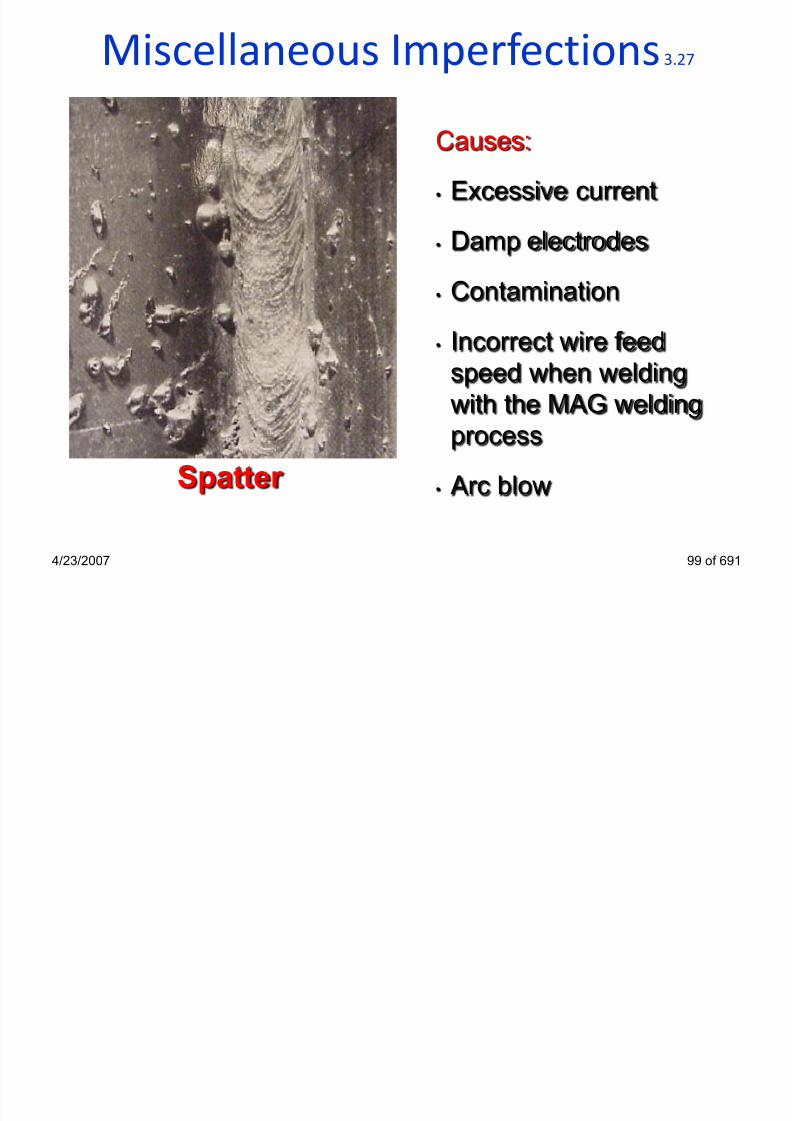
Miscellaneous Imperfections 3.27
7/22/2019 weldinginspectioncswip-100402035204-phpapp02
http://slidepdf.com/reader/full/weldinginspectioncswip-100402035204-phpapp02 99/636
p
4/23/2007 99 of 691
Causes:• Excessive current
• Damp electrodes
• Contamination
• Incorrect wire feed
speed when welding
with the MAG welding
process
• Arc blowSpatter

7/22/2019 weldinginspectioncswip-100402035204-phpapp02
http://slidepdf.com/reader/full/weldinginspectioncswip-100402035204-phpapp02 100/636

7/22/2019 weldinginspectioncswip-100402035204-phpapp02
http://slidepdf.com/reader/full/weldinginspectioncswip-100402035204-phpapp02 101/636

7/22/2019 weldinginspectioncswip-100402035204-phpapp02
http://slidepdf.com/reader/full/weldinginspectioncswip-100402035204-phpapp02 102/636
Qualitative and Quantitative Tests 4.1

7/22/2019 weldinginspectioncswip-100402035204-phpapp02
http://slidepdf.com/reader/full/weldinginspectioncswip-100402035204-phpapp02 103/636
The following mechanical tests have units and are termed
quantitative tests to measure Mechanical Properties• Tensile tests (Transverse Welded Joint, All Weld Metal)
• Toughness testing (Charpy, Izod, CTOD)
• Hardness tests (Brinell, Rockwell, Vickers)
The following mechanical tests have no units and are termed
qualitative tests for assessing joint quality
• Macro testing
• Bend testing
• Fillet weld fracture testing
• Butt weld nick-break testing
4/23/2007 104 of 691
Mechanical Test Samples 4.1

7/22/2019 weldinginspectioncswip-100402035204-phpapp02
http://slidepdf.com/reader/full/weldinginspectioncswip-100402035204-phpapp02 104/636
4/23/2007 105 of 691
Tensile Specimens
Fracture Fillet
Specimen
CTOD Specimen
Charpy Specimen
Bend Test
Specimen
Destructive Testing 4.1

7/22/2019 weldinginspectioncswip-100402035204-phpapp02
http://slidepdf.com/reader/full/weldinginspectioncswip-100402035204-phpapp02 105/636
4/23/2007 106 of 691
Typical Positions for Test
Pieces
Specimen Type Position
•Macro + Hardness 5
•Transverse Tensile 2, 4
•Bend Tests 2, 4
•Charpy Impact Tests 3
•Additional Tests 3
WELDING PROCEDURE QUALIFICATION TESTING
2
3
4
5
top of fixed pipe
7/22/2019 weldinginspectioncswip-100402035204-phpapp02
http://slidepdf.com/reader/full/weldinginspectioncswip-100402035204-phpapp02 106/636

7/22/2019 weldinginspectioncswip-100402035204-phpapp02
http://slidepdf.com/reader/full/weldinginspectioncswip-100402035204-phpapp02 107/636
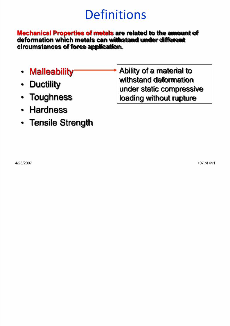
Definitions

7/22/2019 weldinginspectioncswip-100402035204-phpapp02
http://slidepdf.com/reader/full/weldinginspectioncswip-100402035204-phpapp02 108/636
4/23/2007 109 of 691
• Malleability
• Ductility• Toughness
• Hardness
• Tensile Strength
Ability of a material to
withstand bending or the
application of shear
stresses by impact loading
without fracture.
Mechanical Properties of metals are related to the amount ofdeformation which metals can withstand under different
circumstances of force application.

7/22/2019 weldinginspectioncswip-100402035204-phpapp02
http://slidepdf.com/reader/full/weldinginspectioncswip-100402035204-phpapp02 109/636

7/22/2019 weldinginspectioncswip-100402035204-phpapp02
http://slidepdf.com/reader/full/weldinginspectioncswip-100402035204-phpapp02 110/636

7/22/2019 weldinginspectioncswip-100402035204-phpapp02
http://slidepdf.com/reader/full/weldinginspectioncswip-100402035204-phpapp02 111/636

7/22/2019 weldinginspectioncswip-100402035204-phpapp02
http://slidepdf.com/reader/full/weldinginspectioncswip-100402035204-phpapp02 112/636

7/22/2019 weldinginspectioncswip-100402035204-phpapp02
http://slidepdf.com/reader/full/weldinginspectioncswip-100402035204-phpapp02 113/636

7/22/2019 weldinginspectioncswip-100402035204-phpapp02
http://slidepdf.com/reader/full/weldinginspectioncswip-100402035204-phpapp02 114/636

7/22/2019 weldinginspectioncswip-100402035204-phpapp02
http://slidepdf.com/reader/full/weldinginspectioncswip-100402035204-phpapp02 115/636
Ductile / Brittle Transition Curve 4.6

7/22/2019 weldinginspectioncswip-100402035204-phpapp02
http://slidepdf.com/reader/full/weldinginspectioncswip-100402035204-phpapp02 116/636
4/23/2007 117 of 691
- 50 0- 20 - 10- 40 - 30
Ductile fracture
Ductile/Brittletransitionpoint
47 Joules
28 Joules
Testing temperature - Degrees Centigrade
Temperature range
Transition range
Brittle fracture
Three specimens are normally tested at each temperature
Energy absorbed
Comparison Charpy Impact Test Results 4.6

7/22/2019 weldinginspectioncswip-100402035204-phpapp02
http://slidepdf.com/reader/full/weldinginspectioncswip-100402035204-phpapp02 117/636
4/23/2007 118 of 691
Impact Energy Joules
Room Temperature -20oC Temperature
1. 197 Joules
2. 191 Joules3. 186 Joules
1. 49 Joules
2. 53 Joules3. 51 Joules
Average = 191 Joules Average = 51 Joules
The test results show the specimens carried out at room
temperature absorb more energy than the specimens carried
out at -20oC
Charpy V-notch impact test specimen 4.7

7/22/2019 weldinginspectioncswip-100402035204-phpapp02
http://slidepdf.com/reader/full/weldinginspectioncswip-100402035204-phpapp02 118/636
4/23/2007 119 of 691
Specimen dimensions according ASTM E23
ASTM: American Society of Testing Materials

7/22/2019 weldinginspectioncswip-100402035204-phpapp02
http://slidepdf.com/reader/full/weldinginspectioncswip-100402035204-phpapp02 119/636

7/22/2019 weldinginspectioncswip-100402035204-phpapp02
http://slidepdf.com/reader/full/weldinginspectioncswip-100402035204-phpapp02 120/636

7/22/2019 weldinginspectioncswip-100402035204-phpapp02
http://slidepdf.com/reader/full/weldinginspectioncswip-100402035204-phpapp02 121/636
Hardness Testing 4.10

7/22/2019 weldinginspectioncswip-100402035204-phpapp02
http://slidepdf.com/reader/full/weldinginspectioncswip-100402035204-phpapp02 122/636
4/23/2007 123 of 691
Objectives:
• measuring hardness in different areas of a welded joint
• assessing resistance toward brittle fracture, cold cracking
and corrosion sensitivity within a H2S (Hydrogen Sulphide)
environment.
Information to be supplied on the test report:
• material type
• location of indentation
• type of hardness test and load applied on the indenter
• hardness value

7/22/2019 weldinginspectioncswip-100402035204-phpapp02
http://slidepdf.com/reader/full/weldinginspectioncswip-100402035204-phpapp02 123/636
Vickers Hardness Test Machine 4.11

7/22/2019 weldinginspectioncswip-100402035204-phpapp02
http://slidepdf.com/reader/full/weldinginspectioncswip-100402035204-phpapp02 124/636
4/23/2007 125 of 691

7/22/2019 weldinginspectioncswip-100402035204-phpapp02
http://slidepdf.com/reader/full/weldinginspectioncswip-100402035204-phpapp02 125/636
Rockwell Hardness Test

7/22/2019 weldinginspectioncswip-100402035204-phpapp02
http://slidepdf.com/reader/full/weldinginspectioncswip-100402035204-phpapp02 126/636
4/23/2007 127 of 691
1KN
Ø=1.6mm
steel ball
Rockwell B Rockwell C
1.5KN
120 Diamond
Cone

7/22/2019 weldinginspectioncswip-100402035204-phpapp02
http://slidepdf.com/reader/full/weldinginspectioncswip-100402035204-phpapp02 127/636
Crack Tip Opening Displacement testing 4.12

7/22/2019 weldinginspectioncswip-100402035204-phpapp02
http://slidepdf.com/reader/full/weldinginspectioncswip-100402035204-phpapp02 128/636
p p g p g
• Test is for fracture toughness• Square bar machined with a notch placed in
the centre.
• Tested below ambient temperature at aspecified temperature.
• Load is applied at either end of the testspecimen in an attempt to open a crack at the
bottom of the notch
• Normally 3 samples
4/23/2007 129 of 691
Fatigue Fracture 4.13

7/22/2019 weldinginspectioncswip-100402035204-phpapp02
http://slidepdf.com/reader/full/weldinginspectioncswip-100402035204-phpapp02 129/636
4/23/2007 130 of 691
Location: Any stress concentration area
Steel Type: All steel types
Susceptible Microstructure: All grain structures
Test for Fracture Toughness is CTOD
(Crack Tip Opening Displacement)
Fatigue Fracture 4.13

7/22/2019 weldinginspectioncswip-100402035204-phpapp02
http://slidepdf.com/reader/full/weldinginspectioncswip-100402035204-phpapp02 130/636
4/23/2007 131 of 691
• Fatigue cracks occur under cyclic stress conditions
• Fracture normally occurs at a change in section, notchand weld defects i.e stress concentration area
• All materials are susceptible to fatigue cracking
• Fatigue cracking starts at a specific point referred to asa initiation point
• The fracture surface is smooth in appearance
sometimes displaying beach markings
• The final mode of failure may be brittle or ductile or a
combination of both
Fatigue Fracture

7/22/2019 weldinginspectioncswip-100402035204-phpapp02
http://slidepdf.com/reader/full/weldinginspectioncswip-100402035204-phpapp02 131/636
4/23/2007 132 of 691
• Toe grinding, profile grinding.
• The elimination of poor profiles
• The elimination of partial penetration welds and weld
defects
• Operating conditions under the materials endurance limits
• The elimination of notch effects e.g. mechanical damage
cap/root undercut
• The selection of the correct material for the service
conditions of the component
Precautions against Fatigue Cracks

7/22/2019 weldinginspectioncswip-100402035204-phpapp02
http://slidepdf.com/reader/full/weldinginspectioncswip-100402035204-phpapp02 132/636

7/22/2019 weldinginspectioncswip-100402035204-phpapp02
http://slidepdf.com/reader/full/weldinginspectioncswip-100402035204-phpapp02 133/636
Fatigue FractureF ti f t di ti i h f t

7/22/2019 weldinginspectioncswip-100402035204-phpapp02
http://slidepdf.com/reader/full/weldinginspectioncswip-100402035204-phpapp02 134/636
• Crack growth is slow• It initiate from stress concentration points
• load is considerably below the design or yield stress level
• The surface is smooth
• The surface is bounded by a curve
• Bands may sometimes be seen on the smooth surface –”beachmarks”.They show the progress of the crack front from the point of origin
• The surface is 90° to the load
• Final fracture will usually take the form of gross yielding (as themaximum stress in the remaining ligament increase!)
• Fatigue crack need initiation + propagation periods
4/23/2007 135 of 691
Fatigue fracture distinguish features:
Bend Tests 4.15
Object of test:

7/22/2019 weldinginspectioncswip-100402035204-phpapp02
http://slidepdf.com/reader/full/weldinginspectioncswip-100402035204-phpapp02 135/636
4/23/2007 136 of 691
• To determine the soundness of the weld zone. Bend
testing can also be used to give an assessment ofweld zone ductility.
• There are three ways to perform a bend test:
Root bend
Face bend
Side bend
Side bend tests are normally carried out on welds over 12mm in thickness

7/22/2019 weldinginspectioncswip-100402035204-phpapp02
http://slidepdf.com/reader/full/weldinginspectioncswip-100402035204-phpapp02 136/636
Fillet Weld Fracture Tests 4.17

7/22/2019 weldinginspectioncswip-100402035204-phpapp02
http://slidepdf.com/reader/full/weldinginspectioncswip-100402035204-phpapp02 137/636
Object of test:
• To break open the joint through the weld to permitexamination of the fracture surfaces
• Specimens are cut to the required length
• A saw cut approximately 2mm in depth is applied alongthe fillet welds length
• Fracture is usually made by striking the specimen with asingle hammer blow
• Visual inspection for defects
4/23/2007 138 of 691
Fillet Weld Fracture Tests 4.17

7/22/2019 weldinginspectioncswip-100402035204-phpapp02
http://slidepdf.com/reader/full/weldinginspectioncswip-100402035204-phpapp02 138/636
4/23/2007 139 of 691
Fracture should break weld saw cut to root
2mm
Notch
Hammer

7/22/2019 weldinginspectioncswip-100402035204-phpapp02
http://slidepdf.com/reader/full/weldinginspectioncswip-100402035204-phpapp02 139/636
Nick-Break Test 4.18

7/22/2019 weldinginspectioncswip-100402035204-phpapp02
http://slidepdf.com/reader/full/weldinginspectioncswip-100402035204-phpapp02 140/636
Object of test:
• To permit evaluation of any weld defects across the
fracture surface of a butt weld.
• Specimens are cut transverse to the weld
• A saw cut approximately 2mm in depth is applied along thewelds root and cap
• Fracture is usually made by striking the specimen with a
single hammer blow
•Visual inspection for defects
4/23/2007 141 of 691
Nick-Break Test 4.18

7/22/2019 weldinginspectioncswip-100402035204-phpapp02
http://slidepdf.com/reader/full/weldinginspectioncswip-100402035204-phpapp02 141/636
4/23/2007 142 of 691
Approximately 230 mm
19 mm
2 mm
2 mm
Notch cut by hacksaw
Weld reinforcement
may or may not be
removed
Nick Break Test 4.18

7/22/2019 weldinginspectioncswip-100402035204-phpapp02
http://slidepdf.com/reader/full/weldinginspectioncswip-100402035204-phpapp02 142/636
4/23/2007 143 of 691
Inclusions on fracture
lineLack of root penetration
or fusion
Alternative nick-break test
specimen, notch applied all
way around the specimen

7/22/2019 weldinginspectioncswip-100402035204-phpapp02
http://slidepdf.com/reader/full/weldinginspectioncswip-100402035204-phpapp02 143/636
Welding Inspector

7/22/2019 weldinginspectioncswip-100402035204-phpapp02
http://slidepdf.com/reader/full/weldinginspectioncswip-100402035204-phpapp02 144/636
WPS – Welder Qualifications
Section 5
4/23/2007 145 of 691
Welding Procedure Qualification 5.1
Q

7/22/2019 weldinginspectioncswip-100402035204-phpapp02
http://slidepdf.com/reader/full/weldinginspectioncswip-100402035204-phpapp02 145/636
4/23/2007 146 of 691
Question:
What is the main reason for carrying out a Welding ProcedureQualification Test ?
(What is the test try ing to show ?)
Answer:
To show that the welded joint has the properties* that satisfythe design requirements (fit for purpose)
* properties
•mechanical properties are the main interest - always strength buttoughness & hardness may be important for some applications
•test also demonstrates that the weld can be made without defects

7/22/2019 weldinginspectioncswip-100402035204-phpapp02
http://slidepdf.com/reader/full/weldinginspectioncswip-100402035204-phpapp02 146/636
Welding Procedures 5.2
In most codes reference is made to how the procedure are to
b d i d d h h l f h d i

7/22/2019 weldinginspectioncswip-100402035204-phpapp02
http://slidepdf.com/reader/full/weldinginspectioncswip-100402035204-phpapp02 147/636
4/23/2007 148 of 691
be devised and whether approval of these procedures is
required.
The approach used for procedure approval depends on thecode:
Example codes:
• AWS D.1.1: Structural Steel Welding Code
• BS 2633: Class 1 welding of Steel Pipe Work• API 1104: Welding of Pipelines
• BS 4515: Welding of Pipelines over 7 Bar
Other codes may not specifically deal with the requirement of
a procedure but may contain information that may be used in
writing a weld procedure
• EN 1011Process of Arc Welding Steels
Welding Procedure Qualification 5.3

7/22/2019 weldinginspectioncswip-100402035204-phpapp02
http://slidepdf.com/reader/full/weldinginspectioncswip-100402035204-phpapp02 148/636
4/23/2007 149 of 691
The welding engineer writes qualified Welding Procedure
Specifications (WPS) for production welding
Production welding conditions must remain within the range of
qualification allowed by the WPQR
(acco rdin g to EN ISO 15614)
Welding Procedure Qualification 5.3
( d i t EN St d d )

7/22/2019 weldinginspectioncswip-100402035204-phpapp02
http://slidepdf.com/reader/full/weldinginspectioncswip-100402035204-phpapp02 149/636
4/23/2007 150 of 691
(accord ing to EN Stand ards)
welding conditions are called welding variables
welding variables are classified by the EN ISO Standard as:
•Essential variables
•Non-essential variables
•Additional variables
Note: addit ional var iables = ASME su pp lementary essent ia l
The range of qualification for production welding is based on
the limits that the EN ISO Standard specifies for essentialvariables*
( * and when appl icable - the addi t ional var iab les)

7/22/2019 weldinginspectioncswip-100402035204-phpapp02
http://slidepdf.com/reader/full/weldinginspectioncswip-100402035204-phpapp02 150/636
Welding Procedure Qualification 5.3
( d i t EN St d d )

7/22/2019 weldinginspectioncswip-100402035204-phpapp02
http://slidepdf.com/reader/full/weldinginspectioncswip-100402035204-phpapp02 151/636
4/23/2007 152 of 691
(accord ing to EN Standards)
SOME TYPICAL ESSENTIAL VARIABLES
• Welding Process
• Post Weld Heat Treatment (PWHT)
• Material Type
• Electrode Type, Filler Wire Type (Classification)• Material Thickness
• Polarity (AC, DC+ve / DC-ve)
• Pre-Heat Temperature
• Heat Input
• Welding Position

7/22/2019 weldinginspectioncswip-100402035204-phpapp02
http://slidepdf.com/reader/full/weldinginspectioncswip-100402035204-phpapp02 152/636

7/22/2019 weldinginspectioncswip-100402035204-phpapp02
http://slidepdf.com/reader/full/weldinginspectioncswip-100402035204-phpapp02 153/636
Welding Procedures 5.3
Object of a welding procedure test

7/22/2019 weldinginspectioncswip-100402035204-phpapp02
http://slidepdf.com/reader/full/weldinginspectioncswip-100402035204-phpapp02 154/636
4/23/2007 155 of 691
Object of a welding procedure test
To give maximum confidence that the welds mechanicaland metallurgical properties meet the requirements of the
applicable code/specification.
Each welding procedure will show a range to which the
procedure is approved (extent of approval)
If a customer queries the approval evidence can be
supplied to prove its validity

7/22/2019 weldinginspectioncswip-100402035204-phpapp02
http://slidepdf.com/reader/full/weldinginspectioncswip-100402035204-phpapp02 155/636

7/22/2019 weldinginspectioncswip-100402035204-phpapp02
http://slidepdf.com/reader/full/weldinginspectioncswip-100402035204-phpapp02 156/636
4/23/2007 157 of 691
Example:
Welding
Procedure
Specif icat ion
(WPS)

7/22/2019 weldinginspectioncswip-100402035204-phpapp02
http://slidepdf.com/reader/full/weldinginspectioncswip-100402035204-phpapp02 157/636
Welder Qualification 5.4 & 5.5
(accord ing to EN Standards)

7/22/2019 weldinginspectioncswip-100402035204-phpapp02
http://slidepdf.com/reader/full/weldinginspectioncswip-100402035204-phpapp02 158/636
4/23/2007 159 of 691
(accord ing to EN Standards)
Question:What is the main reason for qualifying a welder ?
Answer:
To show that he has the skill to be able to make production
welds that are free from defects
Note: when welding in accordance with a Qual i f ied WPS

7/22/2019 weldinginspectioncswip-100402035204-phpapp02
http://slidepdf.com/reader/full/weldinginspectioncswip-100402035204-phpapp02 159/636

7/22/2019 weldinginspectioncswip-100402035204-phpapp02
http://slidepdf.com/reader/full/weldinginspectioncswip-100402035204-phpapp02 160/636
Welding Procedure Qualification 5.7
(acco rdin g to EN ISO 15614)

7/22/2019 weldinginspectioncswip-100402035204-phpapp02
http://slidepdf.com/reader/full/weldinginspectioncswip-100402035204-phpapp02 161/636
4/23/2007 162 of 691
Test weld is subjected to destructive testing (tensile, bend,
macro)The Application Standard, or Client, may require additional
tests such as impact tests, hardness tests (and for some
materials - corrosion tests)
A Welding Procedure Qualification Record (WPQR) is preparedgiving details of: -
• The welding conditions used for the test weld
• Results of the NDT
• Results of the destructive tests
• The welding conditions that the test weld allows forproduction welding
The Third Party may be requested to sign the WPQR as a true
record

7/22/2019 weldinginspectioncswip-100402035204-phpapp02
http://slidepdf.com/reader/full/weldinginspectioncswip-100402035204-phpapp02 162/636

7/22/2019 weldinginspectioncswip-100402035204-phpapp02
http://slidepdf.com/reader/full/weldinginspectioncswip-100402035204-phpapp02 163/636

7/22/2019 weldinginspectioncswip-100402035204-phpapp02
http://slidepdf.com/reader/full/weldinginspectioncswip-100402035204-phpapp02 164/636

7/22/2019 weldinginspectioncswip-100402035204-phpapp02
http://slidepdf.com/reader/full/weldinginspectioncswip-100402035204-phpapp02 165/636
Material InspectionOne of the most important items to consider is Traceability.

7/22/2019 weldinginspectioncswip-100402035204-phpapp02
http://slidepdf.com/reader/full/weldinginspectioncswip-100402035204-phpapp02 166/636
The materials are of little use if we can not, by use of an effective QAsystem trace them from specification and purchase order to finaldocumentation package handed over to the Client.
All materials arriving on site should be inspected for:
• Size / dimensions
• Condition
• Type / specification
In addition other elements may need to be considered depending onthe materials form or shape
4/23/2007 168 of 691

7/22/2019 weldinginspectioncswip-100402035204-phpapp02
http://slidepdf.com/reader/full/weldinginspectioncswip-100402035204-phpapp02 167/636

7/22/2019 weldinginspectioncswip-100402035204-phpapp02
http://slidepdf.com/reader/full/weldinginspectioncswip-100402035204-phpapp02 168/636
7/22/2019 weldinginspectioncswip-100402035204-phpapp02
http://slidepdf.com/reader/full/weldinginspectioncswip-100402035204-phpapp02 169/636
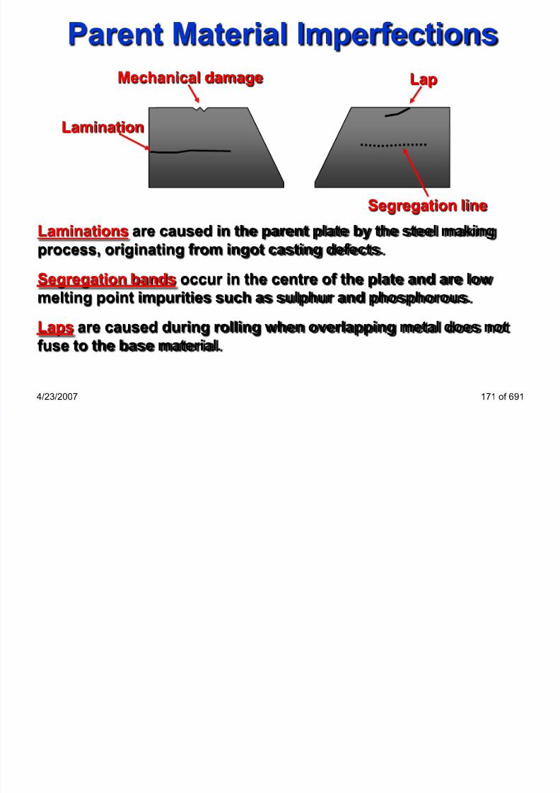
Lapping

7/22/2019 weldinginspectioncswip-100402035204-phpapp02
http://slidepdf.com/reader/full/weldinginspectioncswip-100402035204-phpapp02 170/636
4/23/2007 172 of 691

7/22/2019 weldinginspectioncswip-100402035204-phpapp02
http://slidepdf.com/reader/full/weldinginspectioncswip-100402035204-phpapp02 171/636

7/22/2019 weldinginspectioncswip-100402035204-phpapp02
http://slidepdf.com/reader/full/weldinginspectioncswip-100402035204-phpapp02 172/636

7/22/2019 weldinginspectioncswip-100402035204-phpapp02
http://slidepdf.com/reader/full/weldinginspectioncswip-100402035204-phpapp02 173/636
7/22/2019 weldinginspectioncswip-100402035204-phpapp02
http://slidepdf.com/reader/full/weldinginspectioncswip-100402035204-phpapp02 174/636

7/22/2019 weldinginspectioncswip-100402035204-phpapp02
http://slidepdf.com/reader/full/weldinginspectioncswip-100402035204-phpapp02 175/636

7/22/2019 weldinginspectioncswip-100402035204-phpapp02
http://slidepdf.com/reader/full/weldinginspectioncswip-100402035204-phpapp02 176/636

7/22/2019 weldinginspectioncswip-100402035204-phpapp02
http://slidepdf.com/reader/full/weldinginspectioncswip-100402035204-phpapp02 177/636

7/22/2019 weldinginspectioncswip-100402035204-phpapp02
http://slidepdf.com/reader/full/weldinginspectioncswip-100402035204-phpapp02 178/636

7/22/2019 weldinginspectioncswip-100402035204-phpapp02
http://slidepdf.com/reader/full/weldinginspectioncswip-100402035204-phpapp02 179/636

7/22/2019 weldinginspectioncswip-100402035204-phpapp02
http://slidepdf.com/reader/full/weldinginspectioncswip-100402035204-phpapp02 180/636

7/22/2019 weldinginspectioncswip-100402035204-phpapp02
http://slidepdf.com/reader/full/weldinginspectioncswip-100402035204-phpapp02 181/636

7/22/2019 weldinginspectioncswip-100402035204-phpapp02
http://slidepdf.com/reader/full/weldinginspectioncswip-100402035204-phpapp02 182/636

7/22/2019 weldinginspectioncswip-100402035204-phpapp02
http://slidepdf.com/reader/full/weldinginspectioncswip-100402035204-phpapp02 183/636

7/22/2019 weldinginspectioncswip-100402035204-phpapp02
http://slidepdf.com/reader/full/weldinginspectioncswip-100402035204-phpapp02 184/636

7/22/2019 weldinginspectioncswip-100402035204-phpapp02
http://slidepdf.com/reader/full/weldinginspectioncswip-100402035204-phpapp02 185/636
Arrow Line
(BS EN ISO 22553 & AWS A2.4):

7/22/2019 weldinginspectioncswip-100402035204-phpapp02
http://slidepdf.com/reader/full/weldinginspectioncswip-100402035204-phpapp02 186/636
4/23/2007 188 of 691
Convention of the arrow line:
• Shall touch the joint intersection
• Shall not be parallel to the drawing
• Shall point towards a single plate preparation (when onlyone plate has preparation)

7/22/2019 weldinginspectioncswip-100402035204-phpapp02
http://slidepdf.com/reader/full/weldinginspectioncswip-100402035204-phpapp02 187/636

7/22/2019 weldinginspectioncswip-100402035204-phpapp02
http://slidepdf.com/reader/full/weldinginspectioncswip-100402035204-phpapp02 188/636

7/22/2019 weldinginspectioncswip-100402035204-phpapp02
http://slidepdf.com/reader/full/weldinginspectioncswip-100402035204-phpapp02 189/636
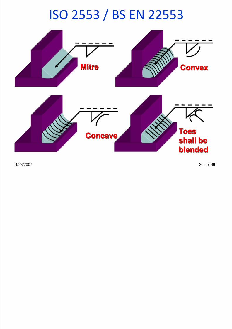
ISO 2553 / BS EN 22553

7/22/2019 weldinginspectioncswip-100402035204-phpapp02
http://slidepdf.com/reader/full/weldinginspectioncswip-100402035204-phpapp02 190/636
4/23/2007 192 of 691
Arrow line
Reference lines
Arrow side
Other side Arrow side
Other side
ISO 2553 / BS EN 22553
M R

7/22/2019 weldinginspectioncswip-100402035204-phpapp02
http://slidepdf.com/reader/full/weldinginspectioncswip-100402035204-phpapp02 191/636
4/23/2007 193 of 691
Single-V Butt flush cap Single-U Butt with sealing run
Single-V Butt with
permanent backing strip
M
Single-U Butt withremovable backing strip

7/22/2019 weldinginspectioncswip-100402035204-phpapp02
http://slidepdf.com/reader/full/weldinginspectioncswip-100402035204-phpapp02 192/636

7/22/2019 weldinginspectioncswip-100402035204-phpapp02
http://slidepdf.com/reader/full/weldinginspectioncswip-100402035204-phpapp02 193/636
ISO 2553 / BS EN 22553
a = Design throat thickness
D th f P t ti Th t

7/22/2019 weldinginspectioncswip-100402035204-phpapp02
http://slidepdf.com/reader/full/weldinginspectioncswip-100402035204-phpapp02 194/636
4/23/2007 196 of 691
s = Depth of Penetration, Throat
thickness
z = Leg length(min material thickness)
a = (0.7 x z)
a 4
4mm Design throat
z 6
6mm leg
az s
s 6
6mm Actual throat

7/22/2019 weldinginspectioncswip-100402035204-phpapp02
http://slidepdf.com/reader/full/weldinginspectioncswip-100402035204-phpapp02 195/636

7/22/2019 weldinginspectioncswip-100402035204-phpapp02
http://slidepdf.com/reader/full/weldinginspectioncswip-100402035204-phpapp02 196/636
ISO 2553 / BS EN 22553
n = number of weld elements
l h f h ld l

7/22/2019 weldinginspectioncswip-100402035204-phpapp02
http://slidepdf.com/reader/full/weldinginspectioncswip-100402035204-phpapp02 197/636
4/23/2007 199 of 691
l = length of each weld element
(e ) = distance between each weld element
n x l (e )
Welds to bestaggered
Process
2 x 40 (50)
3 x 40 (50)111
ISO 2553 / BS EN 22553
All dimensions in mm

7/22/2019 weldinginspectioncswip-100402035204-phpapp02
http://slidepdf.com/reader/full/weldinginspectioncswip-100402035204-phpapp02 198/636
4/23/2007 200 of 691
80 80 80
909090
6
6
5
5
z5
z6
3 x 80 (90)
3 x 80 (90)
All dimensions in mm
ISO 2553 / BS EN 22553
All dimensions in mm

7/22/2019 weldinginspectioncswip-100402035204-phpapp02
http://slidepdf.com/reader/full/weldinginspectioncswip-100402035204-phpapp02 199/636
4/23/2007 201 of 691
All dimensions in mm
8
8
6
6 80 80 80
909090
z8
z6
3 x 80 (90)
3 x 80 (90)

7/22/2019 weldinginspectioncswip-100402035204-phpapp02
http://slidepdf.com/reader/full/weldinginspectioncswip-100402035204-phpapp02 200/636
7/22/2019 weldinginspectioncswip-100402035204-phpapp02
http://slidepdf.com/reader/full/weldinginspectioncswip-100402035204-phpapp02 201/636

7/22/2019 weldinginspectioncswip-100402035204-phpapp02
http://slidepdf.com/reader/full/weldinginspectioncswip-100402035204-phpapp02 202/636
7/22/2019 weldinginspectioncswip-100402035204-phpapp02
http://slidepdf.com/reader/full/weldinginspectioncswip-100402035204-phpapp02 203/636
ISO 2553 / BS EN 22553
a = Design throat thickness
s = Depth of Penetration Throat

7/22/2019 weldinginspectioncswip-100402035204-phpapp02
http://slidepdf.com/reader/full/weldinginspectioncswip-100402035204-phpapp02 204/636
4/23/2007 206 of 691
s = Depth of Penetration, Throat
thickness
z = Leg length(min material thickness)
a = (0.7 x z)
a 4
4mm Design throat
z 6
6mm leg
az s
s 6
6mm Actual throat

7/22/2019 weldinginspectioncswip-100402035204-phpapp02
http://slidepdf.com/reader/full/weldinginspectioncswip-100402035204-phpapp02 205/636
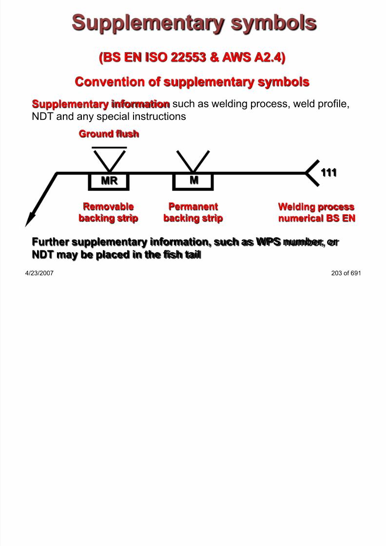
ISO 2553 / BS EN 22553
Numerical Values for Welding Processes:

7/22/2019 weldinginspectioncswip-100402035204-phpapp02
http://slidepdf.com/reader/full/weldinginspectioncswip-100402035204-phpapp02 206/636
4/23/2007 208 of 691
111: MMA welding with covered electrode121: Sub-arc welding with wire electrode
131: MIG welding with inert gas shield
135: MAG welding with non-inert gas shield
136: Flux core arc welding
141: TIG welding
311: Oxy-acetylene welding
72: Electro-slag welding
15: Plasma arc welding

7/22/2019 weldinginspectioncswip-100402035204-phpapp02
http://slidepdf.com/reader/full/weldinginspectioncswip-100402035204-phpapp02 207/636

7/22/2019 weldinginspectioncswip-100402035204-phpapp02
http://slidepdf.com/reader/full/weldinginspectioncswip-100402035204-phpapp02 208/636
AWS Welding Symbols

7/22/2019 weldinginspectioncswip-100402035204-phpapp02
http://slidepdf.com/reader/full/weldinginspectioncswip-100402035204-phpapp02 209/636
4/23/2007 211 of 691
1(1-1/8)
60o1/8
GSFCAW
Welding Process
GMAW
GTAW
SAW
AWS Welding Symbols
Welds to bet d

7/22/2019 weldinginspectioncswip-100402035204-phpapp02
http://slidepdf.com/reader/full/weldinginspectioncswip-100402035204-phpapp02 210/636
4/23/2007 212 of 691
3 – 10
3 – 10
staggered
SMAW
Process
10
3 3
AWS Welding Symbols

7/22/2019 weldinginspectioncswip-100402035204-phpapp02
http://slidepdf.com/reader/full/weldinginspectioncswip-100402035204-phpapp02 211/636
4/23/2007 213 of 691
1(1-1/8)
60o
1/8
FCAW
Sequence of
Operations
1st Operation
2nd Operation
3rd Operation
AWS Welding Symbols

7/22/2019 weldinginspectioncswip-100402035204-phpapp02
http://slidepdf.com/reader/full/weldinginspectioncswip-100402035204-phpapp02 212/636
4/23/2007 214 of 691
1(1-1/8)
60o
1/8
FCAW
Sequence of
Operations
RT
MT
MT
AWS Welding Symbols
Dimensions- Leg Length

7/22/2019 weldinginspectioncswip-100402035204-phpapp02
http://slidepdf.com/reader/full/weldinginspectioncswip-100402035204-phpapp02 213/636
4/23/2007 215 of 691
6/8
6 leg on member A
8
6Member A
Member B
Welding Inspector

7/22/2019 weldinginspectioncswip-100402035204-phpapp02
http://slidepdf.com/reader/full/weldinginspectioncswip-100402035204-phpapp02 214/636
Intro To Welding ProcessesSection 9
4/23/2007 221 of 691
Welding ProcessesWelding is regarded as a joining process in which the work
pieces are in atomic contact

7/22/2019 weldinginspectioncswip-100402035204-phpapp02
http://slidepdf.com/reader/full/weldinginspectioncswip-100402035204-phpapp02 215/636
4/23/2007 222 of 691
Pressure welding
• Forge welding
• Friction welding
• Resistance Welding
Fusion welding
• Oxy-acetylene
• MMA (SMAW)
• MIG/MAG (GMAW)• TIG (GTAW)
• Sub-arc (SAW)
• Electro-slag (ESW)
• Laser Beam (LBW)
• Electron-Beam (EBW)
7/22/2019 weldinginspectioncswip-100402035204-phpapp02
http://slidepdf.com/reader/full/weldinginspectioncswip-100402035204-phpapp02 216/636

7/22/2019 weldinginspectioncswip-100402035204-phpapp02
http://slidepdf.com/reader/full/weldinginspectioncswip-100402035204-phpapp02 217/636
Monitoring Heat Input

7/22/2019 weldinginspectioncswip-100402035204-phpapp02
http://slidepdf.com/reader/full/weldinginspectioncswip-100402035204-phpapp02 218/636
4/23/2007 228 of 691
Weld and weld pool temperatures
Monitoring Heat Input

7/22/2019 weldinginspectioncswip-100402035204-phpapp02
http://slidepdf.com/reader/full/weldinginspectioncswip-100402035204-phpapp02 219/636
4/23/2007 229 of 691
Monitoring Heat Input
• Monitoring Heat Input As Required by

7/22/2019 weldinginspectioncswip-100402035204-phpapp02
http://slidepdf.com/reader/full/weldinginspectioncswip-100402035204-phpapp02 220/636
• BS EN ISO 15614-1:2004
• In accordance with EN 1011-1:1998
4/23/2007 230 of 691
When impact requirements and/or hardness requirements are
specified impact test shall be taken from the weld in the highestheat input position and hardness tests shall be taken from the
weld in the lowest heat input position in order to qualify for all
positions
Welding Inspector

7/22/2019 weldinginspectioncswip-100402035204-phpapp02
http://slidepdf.com/reader/full/weldinginspectioncswip-100402035204-phpapp02 221/636
MMA WeldingSection 10
4/23/2007 231 of 691
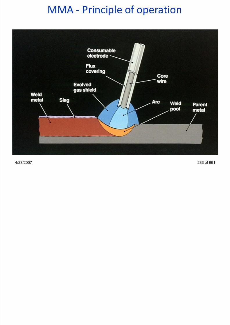
MMA - Principle of operation
7/22/2019 weldinginspectioncswip-100402035204-phpapp02
http://slidepdf.com/reader/full/weldinginspectioncswip-100402035204-phpapp02 222/636
4/23/2007 233 of 691

7/22/2019 weldinginspectioncswip-100402035204-phpapp02
http://slidepdf.com/reader/full/weldinginspectioncswip-100402035204-phpapp02 223/636
Manual Metal Arc Basic Equipment

7/22/2019 weldinginspectioncswip-100402035204-phpapp02
http://slidepdf.com/reader/full/weldinginspectioncswip-100402035204-phpapp02 224/636
4/23/2007 235 of 691
Power source
Holding oven
Inverter power
source
Electrode holder
Power cablesWelding visorfilter glass
Return lead
Electrodes
Electrode
oven
Control panel
(amps, volts)

7/22/2019 weldinginspectioncswip-100402035204-phpapp02
http://slidepdf.com/reader/full/weldinginspectioncswip-100402035204-phpapp02 225/636
MMA Welding VariablesVoltage
• The arc voltage in the MMA process is measured as close to

7/22/2019 weldinginspectioncswip-100402035204-phpapp02
http://slidepdf.com/reader/full/weldinginspectioncswip-100402035204-phpapp02 226/636
4/23/2007 237 of 691
the arc as possible. It is variable with a change in arc lengthO.C.V.
• The open circuit voltage is the voltage required to initiate, or
re-ignite the electrical arc and will change with the type of
electrode being used e.g 70-90 volts
Current
• The current used will be determined by the choice of
electrode, electrode diameter and material type and
thickness. Current has the most effect on penetration.
Polarity• Polarity is generally determined by operation and electrode
type e.g DC +ve, DC –ve or AC
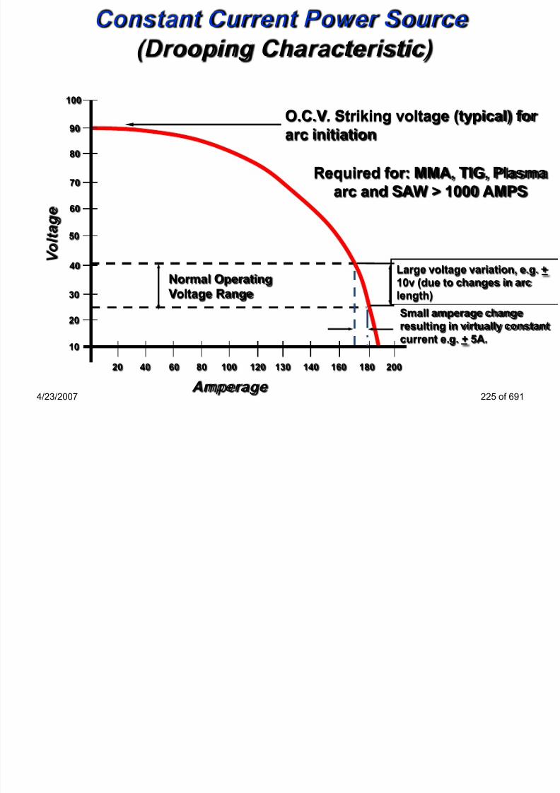
100
O C V Striking voltage (typical) for arc
Constant Current Power Source(Drooping Characteristic)

7/22/2019 weldinginspectioncswip-100402035204-phpapp02
http://slidepdf.com/reader/full/weldinginspectioncswip-100402035204-phpapp02 227/636
4/23/2007 239 of 691
20 8040 60 130 140120100 180160 200
10
60
50
40
30
20
80
70
90
Normal Operating
Voltage Range
Large voltage variation, e.g. +
10v (due to changes in arc
length)
Small amperage change
resulting in virtually constant
current e.g. + 5A.
V o l t a g
e
Amperage
O.C.V. Striking voltage (typical) for arc
initiation
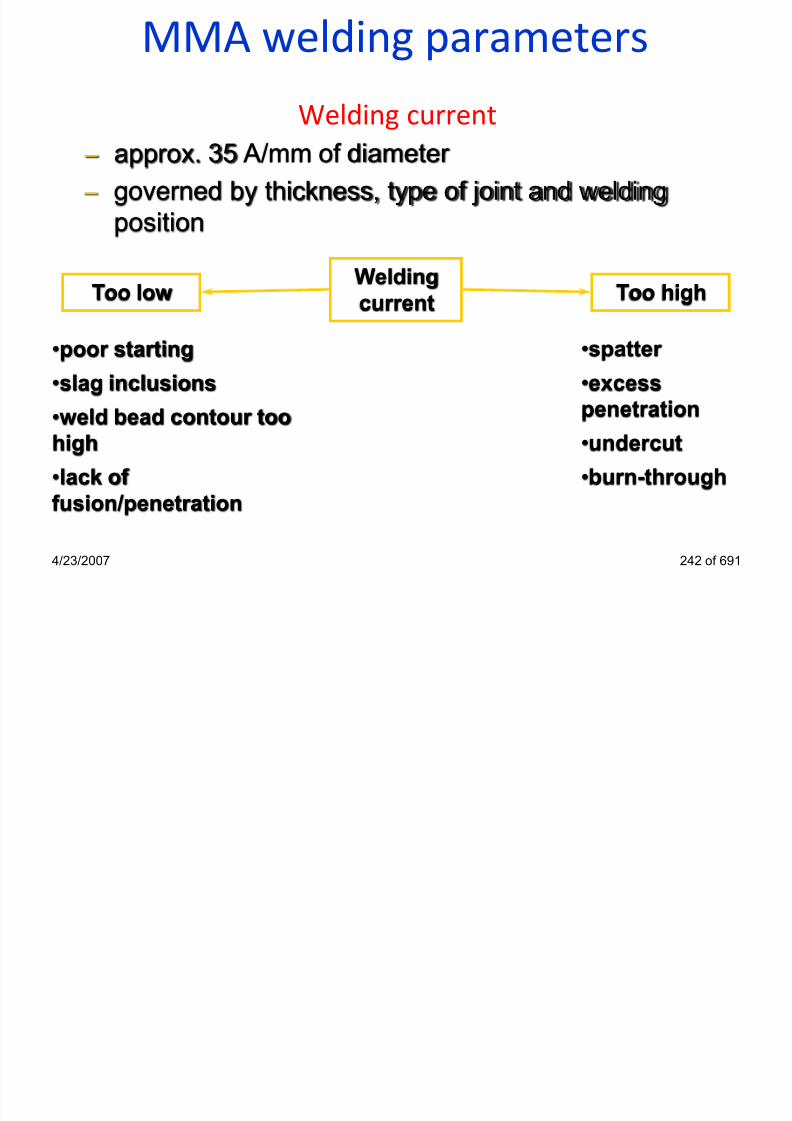
MMA welding parametersTravel speed

7/22/2019 weldinginspectioncswip-100402035204-phpapp02
http://slidepdf.com/reader/full/weldinginspectioncswip-100402035204-phpapp02 228/636
4/23/2007 240 of 691
Travelspeed
Too highToo low
•wide weld bead contour
•lack of penetration
•burn-through
•lack of root fusion
•incomplete root
penetration•undercut
•poor bead profile,
difficult slag removal
MMA welding parameters
Type of current:
• voltage drop in welding cables is lower with AC

7/22/2019 weldinginspectioncswip-100402035204-phpapp02
http://slidepdf.com/reader/full/weldinginspectioncswip-100402035204-phpapp02 229/636
g p g
• inductive looses can appear with AC if cables are coiled
• cheaper power source for AC
• no problems with arc blow with AC
• DC provides a more stable and easy to strike arc, especially
with low current, better positional weld, thin sheet applications
• welding with a short arc length (low arc voltage) is easier with
DC, better mechanical properties
• DC provides a smoother metal transfer, less spatter
4/23/2007 241 of 691
7/22/2019 weldinginspectioncswip-100402035204-phpapp02
http://slidepdf.com/reader/full/weldinginspectioncswip-100402035204-phpapp02 230/636
MMA welding parametersArc length = arc voltage
Arc

7/22/2019 weldinginspectioncswip-100402035204-phpapp02
http://slidepdf.com/reader/full/weldinginspectioncswip-100402035204-phpapp02 231/636
4/23/2007 243 of 691
Arc
voltage Too highToo low
•arc can be extinguished
•“stubbing”
•spatter
•porosity
•excesspenetration
•undercut
•burn-through
Polarity: DCEP generally gives deeper penetration

7/22/2019 weldinginspectioncswip-100402035204-phpapp02
http://slidepdf.com/reader/full/weldinginspectioncswip-100402035204-phpapp02 232/636
MMA electrode holder

7/22/2019 weldinginspectioncswip-100402035204-phpapp02
http://slidepdf.com/reader/full/weldinginspectioncswip-100402035204-phpapp02 233/636
4/23/2007 245 of 691
Collet or twist type“Tongs” type with
spring-loaded jaws
MMA Welding Consumables

7/22/2019 weldinginspectioncswip-100402035204-phpapp02
http://slidepdf.com/reader/full/weldinginspectioncswip-100402035204-phpapp02 234/636
4/23/2007 246 of 691
The three main electrode covering types used in MMA welding
• Cellulosic - deep penetration/fusion
• Rutile - general purpose
• Basic - low hydrogen
(Covered in more detail in Section 14)
MMA Covered Electrodes
Most welding defects in MMA are caused by a lack of welder
skill (not an easily controlled process), the incorrect settings
MMA welding typical defects

7/22/2019 weldinginspectioncswip-100402035204-phpapp02
http://slidepdf.com/reader/full/weldinginspectioncswip-100402035204-phpapp02 235/636
4/23/2007 247 of 691
of the equipment, or the incorrect use, and treatment ofelectrodes
Typical Welding Defects:
•Slag inclusions
•Arc strikes
•Porosity
•Undercut
•Shape defects (overlap, excessive root penetration, etc.)
Manual Metal Arc Welding (MMA)
Advantages:
• Field or shop use

7/22/2019 weldinginspectioncswip-100402035204-phpapp02
http://slidepdf.com/reader/full/weldinginspectioncswip-100402035204-phpapp02 236/636
4/23/2007 248 of 691
• Range of consumables• All positions
• Portable
• Simple equipment
Disadvantages:• High welder skill required
• High levels of fume
• Hydrogen control (flux)
• Stop/start problems
• Comparatively uneconomic when compared with someother processes i.e MAG, SAW and FCAW
Welding Inspector

7/22/2019 weldinginspectioncswip-100402035204-phpapp02
http://slidepdf.com/reader/full/weldinginspectioncswip-100402035204-phpapp02 237/636
TIG WeldingSection 11
4/23/2007 249 of 691
Tungsten Inert Gas WeldingThe TIG welding process was first developed in the USA
during the 2nd world war for the welding of aluminum alloys

7/22/2019 weldinginspectioncswip-100402035204-phpapp02
http://slidepdf.com/reader/full/weldinginspectioncswip-100402035204-phpapp02 238/636
4/23/2007 250 of 691
• The process uses a non-consumable tungsten electrode
• The process requires a high level of welder skill
• The process produces very high quality welds.
• The TIG process is considered as a slow process comparedto other arc welding processes
• The arc may be initiated by a high frequency to avoid scratch
starting, which could cause contamination of the tungsten
and weld
TIG - Principle of operation

7/22/2019 weldinginspectioncswip-100402035204-phpapp02
http://slidepdf.com/reader/full/weldinginspectioncswip-100402035204-phpapp02 239/636
4/23/2007 251 of 691
TIG Welding Variables
Voltage
The voltage of the TIG welding process is variable only by the

7/22/2019 weldinginspectioncswip-100402035204-phpapp02
http://slidepdf.com/reader/full/weldinginspectioncswip-100402035204-phpapp02 240/636
4/23/2007 254 of 691
type of gas being used, and changes in the arc length
Current
The current is adjusted proportionally to the tungsten
electrodes diameter being used. The higher the current thedeeper the penetration and fusion
Polarity
The polarity used for steels is always DC –ve as most of the
heat is concentrated at the +ve pole, this is required to keepthe tungsten electrode at the cool end of the arc. When
welding aluminium and its alloys AC current is used
Types of current• can be DCEN or DCEP
• DCEN gives deep penetrationDC
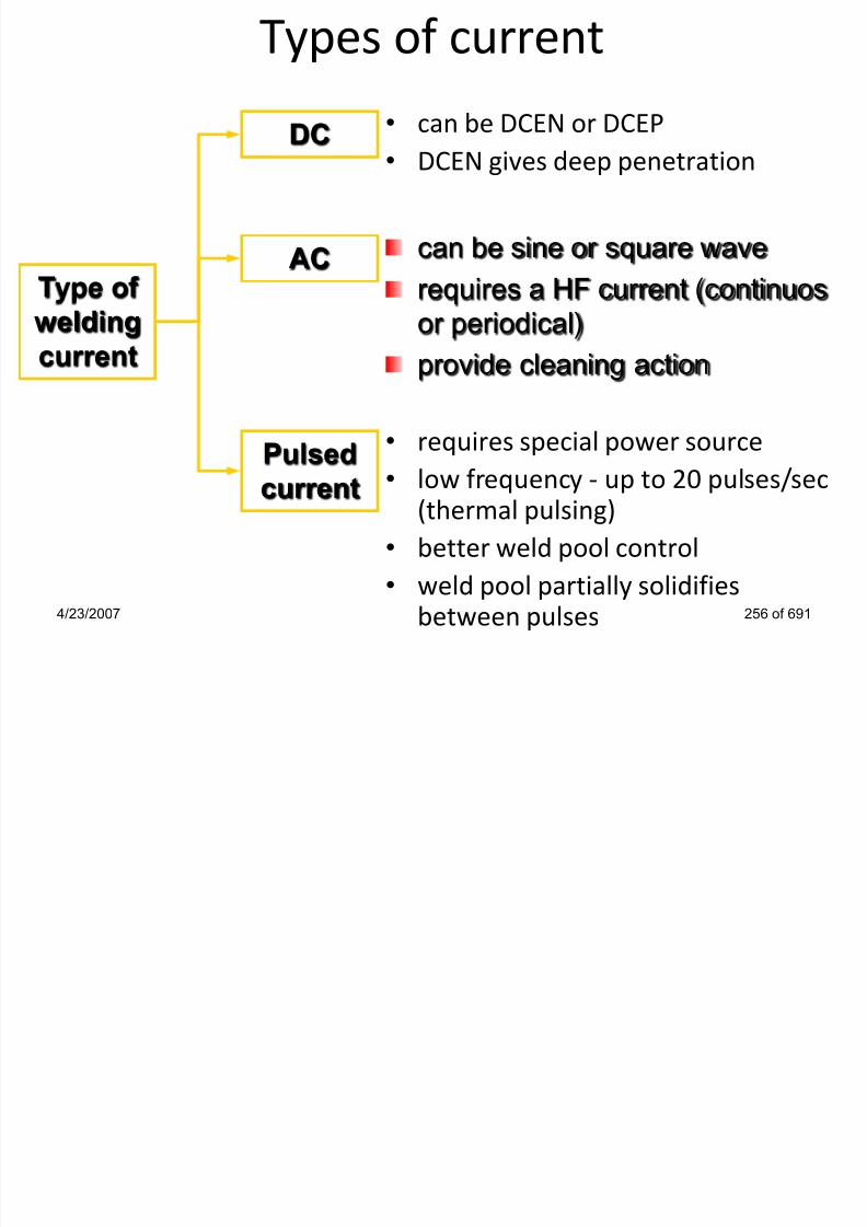
7/22/2019 weldinginspectioncswip-100402035204-phpapp02
http://slidepdf.com/reader/full/weldinginspectioncswip-100402035204-phpapp02 241/636
• requires special power source
• low frequency - up to 20 pulses/sec(thermal pulsing)
• better weld pool control
• weld pool partially solidifiesbetween pulses4/23/2007 256 of 691
Type of
welding
current
can be sine or square wave
requires a HF current (continuos
or periodical)
provide cleaning action
AC
Pulsed
current

7/22/2019 weldinginspectioncswip-100402035204-phpapp02
http://slidepdf.com/reader/full/weldinginspectioncswip-100402035204-phpapp02 242/636
ARC CHARACTERISTICSConstant Current/Amperage Characteristic

7/22/2019 weldinginspectioncswip-100402035204-phpapp02
http://slidepdf.com/reader/full/weldinginspectioncswip-100402035204-phpapp02 243/636
4/23/2007 258 of 691
Volts
Amps
OCV
Large change in voltage =Smaller change in amperage
Welding VoltageLarge arc gap
Small arc
gap
TIG - arc initiation methods
Arc initiation
method

7/22/2019 weldinginspectioncswip-100402035204-phpapp02
http://slidepdf.com/reader/full/weldinginspectioncswip-100402035204-phpapp02 244/636
• simple method
• tungsten electrode is in contactwith the workpiece!
• high initial arc current due to theshort circuit
• impractical to set arc length inadvance
• electrode should tap theworkpiece - no scratch!
• ineffective in case of AC• used when a high quality is not
essential
4/23/2007 259 of 691
Lift arc HF start
need a HF generator (spark-
gap oscillator) that generates a
high voltage AC output (radio
frequency) costly
reliable method required on
both DC (for start) and AC (to
re-ignite the arc)
can be used remotely
HF produce interference
requires superior insulation
Pulsed current• usually peak current is 2-10 times
background current ( A )
Pulse
time
Cycle
time
Peak
current
Background
current

7/22/2019 weldinginspectioncswip-100402035204-phpapp02
http://slidepdf.com/reader/full/weldinginspectioncswip-100402035204-phpapp02 245/636
• useful on metals sensitive to high heatinput
• reduced distortions
• in case of dissimilar thicknesses equal
penetration can be achieved
4/23/2007 260 of 691
Time
C u r r e n t
Average current
one set of variables can be used in all positionsused for bridging gaps in open root joints
require special power source
Choosing the proper electrode
Polarity Influence – cathodic cleaning effect

7/22/2019 weldinginspectioncswip-100402035204-phpapp02
http://slidepdf.com/reader/full/weldinginspectioncswip-100402035204-phpapp02 246/636
4/23/2007 261 of 691
Tungsten Electrodes
Old types: (Slightly Radioactive)
• Thoriated: DC electrode -ve - steels and most metals

7/22/2019 weldinginspectioncswip-100402035204-phpapp02
http://slidepdf.com/reader/full/weldinginspectioncswip-100402035204-phpapp02 247/636
4/23/2007 262 of 691
• 1% thoriated + tungsten for higher current values
• 2% thoriated for lower current values
• Zirconiated: AC - aluminum alloys and magnesium
New types: (Not Radioactive)
• Cerium: DC electrode -ve - steels and most metals
• Lanthanum: AC - Aluminum alloys and magnesium
TIG torch set-up• Electrode extension

7/22/2019 weldinginspectioncswip-100402035204-phpapp02
http://slidepdf.com/reader/full/weldinginspectioncswip-100402035204-phpapp02 248/636
4/23/2007 263 of 691
Electrode
extension
Stickout 2-3 times
electrode
diameter
Electrode
extension
Low electron
emission
Unstable arc
Too
small
Overheating
Tungsten
inclusions
Too
large
Choosing the correct electrode
Polarity Influence – cathodic cleaning effect

7/22/2019 weldinginspectioncswip-100402035204-phpapp02
http://slidepdf.com/reader/full/weldinginspectioncswip-100402035204-phpapp02 249/636
4/23/2007 264 of 691
Tungsten ElectrodesOld types: (Slightly Radioactive)
• Thoriated: DC electrode -ve - steels and most metals

7/22/2019 weldinginspectioncswip-100402035204-phpapp02
http://slidepdf.com/reader/full/weldinginspectioncswip-100402035204-phpapp02 250/636
4/23/2007 265 of 691
• 1% thoriated + tungsten for higher current values
• 2% thoriated for lower current values
• Zirconiated: AC - aluminum alloys and magnesium
New types: (Not Radioactive)
• Cerium: DC electrode -ve - steels and most metals
• Lanthanum: AC - Aluminum alloys and magnesium
Tungsten electrode typesPure tungsten electrodes:
colour code - green

7/22/2019 weldinginspectioncswip-100402035204-phpapp02
http://slidepdf.com/reader/full/weldinginspectioncswip-100402035204-phpapp02 251/636
4/23/2007 266 of 691
no alloy additions
low current carrying capacity
maintains a clean balled end
can be used for AC welding of Al and Mg alloys
poor arc initiation and arc stability with AC compared
with other electrode types
used on less critical applications
low cost
Tungsten electrode typesThoriated tungsten electrodes:
l d ll / d/ i l t

7/22/2019 weldinginspectioncswip-100402035204-phpapp02
http://slidepdf.com/reader/full/weldinginspectioncswip-100402035204-phpapp02 252/636
4/23/2007 267 of 691
colour code - yellow/red/violet
20% higher current carrying capacity compared to
pure tungsten electrodes
longer life - greater resistance to contaminationthermionic - easy arc initiation, more stable arc
maintain a sharpened tip
recommended for DCEN, seldom used on AC(difficult to maintain a balled tip)
This slightly radioactive
Tungsten electrode typesCeriated tungsten electrodes:
l d ( AWS A 5 12)

7/22/2019 weldinginspectioncswip-100402035204-phpapp02
http://slidepdf.com/reader/full/weldinginspectioncswip-100402035204-phpapp02 253/636
4/23/2007 268 of 691
colour code - grey (orange acc. AWS A-5.12)
operate successfully with AC or DC
Ce not radioactive - replacement for thoriated types
Lanthaniated tungsten electrodes:
colour code - black/gold/blue
operating characteristics similar with ceriated
electrode
Tungsten electrode typesZirconiated tungsten electrodes:
colour code brown/white

7/22/2019 weldinginspectioncswip-100402035204-phpapp02
http://slidepdf.com/reader/full/weldinginspectioncswip-100402035204-phpapp02 254/636
4/23/2007 269 of 691
colour code - brown/white
operating characteristics fall between those of pure
and thoriated electrodes
retains a balled end during welding - good for ACwelding
high resistance to contamination
preferred for radiographic quality welds
Electrode tip for DCENPenetration
increase r
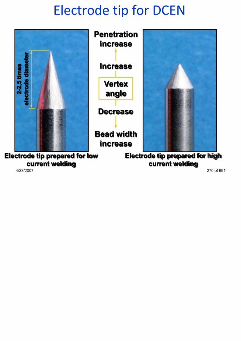
7/22/2019 weldinginspectioncswip-100402035204-phpapp02
http://slidepdf.com/reader/full/weldinginspectioncswip-100402035204-phpapp02 255/636
4/23/2007 270 of 691
Electrode tip prepared for low
current welding
Electrode tip prepared for high
current welding
Vertex
angle
Increase
Bead width
increase
Decrease
2 - 2 , 5
t i m e s
e l e c
t r o d e d i a m e t e

7/22/2019 weldinginspectioncswip-100402035204-phpapp02
http://slidepdf.com/reader/full/weldinginspectioncswip-100402035204-phpapp02 256/636
TIG Welding VariablesTungsten electrodes
The electrode diameter, type and vertex angle are all critical
factors considered as essential variables The vertex angle is

7/22/2019 weldinginspectioncswip-100402035204-phpapp02
http://slidepdf.com/reader/full/weldinginspectioncswip-100402035204-phpapp02 257/636
4/23/2007 272 of 691
factors considered as essential variables. The vertex angle isas shown
Vetex angle
Note: when welding
aluminium with ACcurrent, the tungsten end
is chamfered and forms a
ball end when welding
DC -ve
Note: too fine an angle will
promote melting of the
electrodes tip
AC
Choosing the proper electrodeFactors to be considered:

7/22/2019 weldinginspectioncswip-100402035204-phpapp02
http://slidepdf.com/reader/full/weldinginspectioncswip-100402035204-phpapp02 258/636
4/23/2007 273 of 691
Unstable
arc
Tungsten
inclusions
Welding
current
Electrode tip
not properly
heated
Excessive
melting or
volatilisation
Too
low
Too
high
Penetration
Shielding gas requirements
• Preflow andpostflow
Shielding gas flow
Welding current

7/22/2019 weldinginspectioncswip-100402035204-phpapp02
http://slidepdf.com/reader/full/weldinginspectioncswip-100402035204-phpapp02 259/636
4/23/2007 275 of 691
Preflow Postflow
Flow rate
too low
Flow rate
too high
Special shielding methodsPipe root run shielding – Back Purging to prevent
excessive oxidation during welding, normally argon.

7/22/2019 weldinginspectioncswip-100402035204-phpapp02
http://slidepdf.com/reader/full/weldinginspectioncswip-100402035204-phpapp02 260/636
4/23/2007 276 of 691
TIG torch set-upElectrode extension
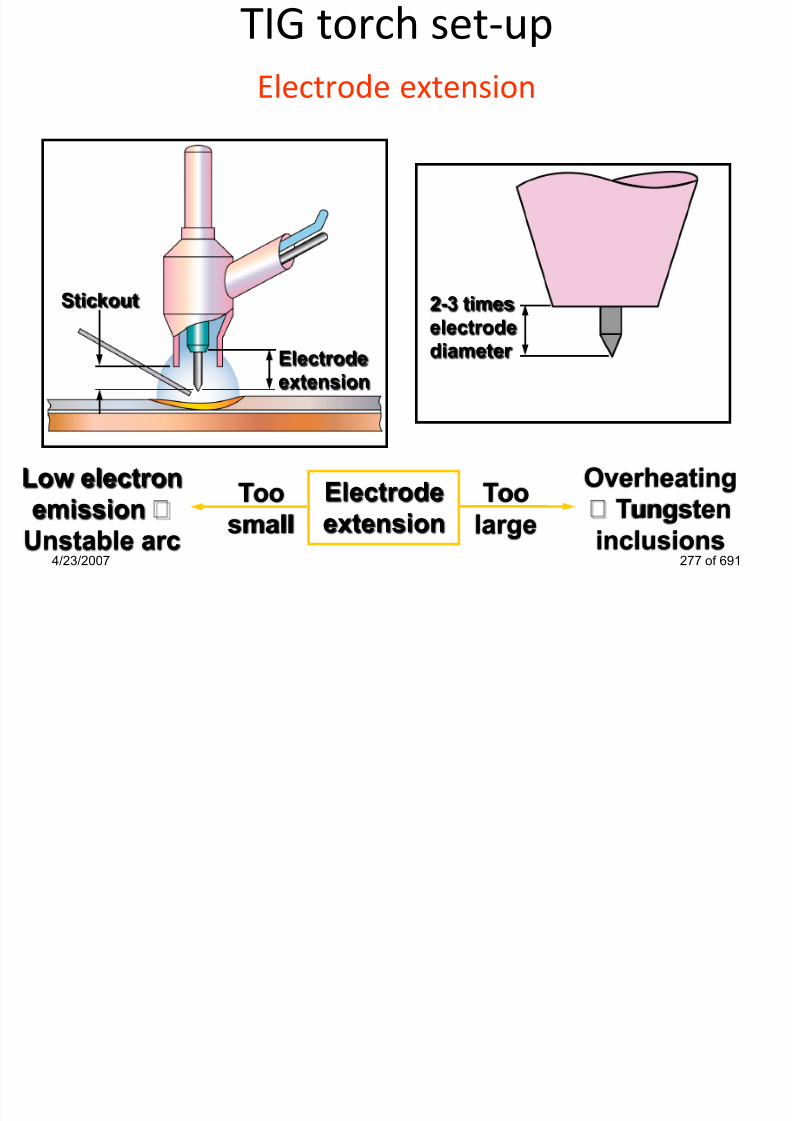
7/22/2019 weldinginspectioncswip-100402035204-phpapp02
http://slidepdf.com/reader/full/weldinginspectioncswip-100402035204-phpapp02 261/636
4/23/2007 277 of 691
Electrode
extension
Stickout 2-3 times
electrodediameter
Electrode
extension
Low electron
emission
Unstable arc
Too
small
Overheating
Tungsten
inclusions
Too
large
TIG Welding ConsumablesWelding consumables for TIG:
•Filler wires, Shielding gases, tungsten electrodes (non-
bl )

7/22/2019 weldinginspectioncswip-100402035204-phpapp02
http://slidepdf.com/reader/full/weldinginspectioncswip-100402035204-phpapp02 262/636
consumable).
•Filler wires of different materials composition and variable
diameters available in standard lengths, with applicable
code stamped for identification
•Steel Filler wires of very high quality, with copper coating to
resist corrosion.
•shielding gases mainly Argon and Helium, usually of highest
purity (99.9%).
4/23/2007 278 of 691
Tungsten Inclusion
May be caused by Thermal Shock of
heating to fast and small fragments

7/22/2019 weldinginspectioncswip-100402035204-phpapp02
http://slidepdf.com/reader/full/weldinginspectioncswip-100402035204-phpapp02 263/636
4/23/2007 279 of 691
A Tungsten Inclusion always shows up as
bright white on a radiograph
heating to fast and small fragmentsbreak off and enter the weld pool, so a
“slope up” device is normally fitted to
prevent this could be caused by touch
down also.
Most TIG sets these days have slope-up devices that brings the current to
the set level over a short period of
time so the tungsten is heated more
slowly and gently
Most welding defects with TIG are caused by a lack of welder
skill, or incorrect setting of the equipment. i.e. current, torch
manipulation, welding speed, gas flow rate, etc.
TIG typical defects

7/22/2019 weldinginspectioncswip-100402035204-phpapp02
http://slidepdf.com/reader/full/weldinginspectioncswip-100402035204-phpapp02 264/636
4/23/2007 280 of 691
• Tungsten inclusions (low skill or wrong vertex angle)
• Surface porosity (loss of gas shield mainly on site)
• Crater pipes (bad weld finish technique i.e. slope out)
• Oxidation of S/S weld bead, or root by poor gas cover
• Root concavity (excess purge pressure in pipe)
• Lack of penetration/fusion (widely on root runs)
Tungsten Inert Gas WeldingAdvantages
• High quality
Disadvantages
• High skill factor required

7/22/2019 weldinginspectioncswip-100402035204-phpapp02
http://slidepdf.com/reader/full/weldinginspectioncswip-100402035204-phpapp02 265/636
• High quality
• Good control
• All positions
• Lowest H2 process
• Minimal cleaning
• Autogenous welding
(No filler material)
• Can be automated
• High skill factor required
• Low deposition rate
• Small consumable range
• High protection required
• Complex equipment
• Low productivity
• High ozone levels +HF
4/23/2007 281 of 691
Welding Inspector
MIG/MAG Welding

7/22/2019 weldinginspectioncswip-100402035204-phpapp02
http://slidepdf.com/reader/full/weldinginspectioncswip-100402035204-phpapp02 266/636
MIG/MAG WeldingSection 12
4/23/2007 282 of 691
Gas Metal Arc WeldingThe MIG/MAG welding process was initially developed in the
USA in the late 1940s for the welding of aluminum alloys.
The latest EN Welding Standards now refer the process by the

7/22/2019 weldinginspectioncswip-100402035204-phpapp02
http://slidepdf.com/reader/full/weldinginspectioncswip-100402035204-phpapp02 267/636
4/23/2007 283 of 691
The latest EN Welding Standards now refer the process by theAmerican term GMAW (Gas Metal Arc Welding)
• The process uses a continuously fed wire electrode
• The weld pool is protected by a separately supplied
shielding gas
• The process is classified as a semi-automatic welding
process but may be fully automated
• The wire electrode can be either bare/solid wire or flux
cored hollow wire
MIG/MAG - Principle of operation

7/22/2019 weldinginspectioncswip-100402035204-phpapp02
http://slidepdf.com/reader/full/weldinginspectioncswip-100402035204-phpapp02 268/636
4/23/2007 284 of 691
MIG/MAG process variables• Welding current

7/22/2019 weldinginspectioncswip-100402035204-phpapp02
http://slidepdf.com/reader/full/weldinginspectioncswip-100402035204-phpapp02 269/636
• Polarity
4/23/2007 286 of 691
•Increasing welding current
•Increase in depth and width
•Increase in deposition rate
MIG/MAG process variables
• Arc voltage

7/22/2019 weldinginspectioncswip-100402035204-phpapp02
http://slidepdf.com/reader/full/weldinginspectioncswip-100402035204-phpapp02 270/636
• Travel speed
4/23/2007 287 of 691
•Increasing travel speed
•Reduced penetration and width, undercut
•Increasing arc voltage
•Reduced penetration, increased width•Excessive voltage can cause porosity,
spatter and undercut
Gas Metal Arc WeldingTypes of Shielding Gas
MIG (Metal Inert Gas)

7/22/2019 weldinginspectioncswip-100402035204-phpapp02
http://slidepdf.com/reader/full/weldinginspectioncswip-100402035204-phpapp02 271/636
4/23/2007 289 of 691
• Inert Gas is required for all non-ferrous alloys (Al, Cu, Ni)
• Most common inert gas is Argon
• Argon + Helium used to give a „hotter‟ arc - better for thicker
joints and alloys with higher thermal conductivity
MIG/MAG – shielding gases
Type of material Shielding gas

7/22/2019 weldinginspectioncswip-100402035204-phpapp02
http://slidepdf.com/reader/full/weldinginspectioncswip-100402035204-phpapp02 272/636
4/23/2007 290 of 691
Carbon steel
Stainless steel
Aluminium
CO2 , Ar+(5-20)%CO2
Ar+2%O2
Ar
MIG/MAG shielding gases
A (A )
Ar Ar-He He CO2

7/22/2019 weldinginspectioncswip-100402035204-phpapp02
http://slidepdf.com/reader/full/weldinginspectioncswip-100402035204-phpapp02 273/636
Argon (Ar):
higher density than air; low thermal conductivity the archas a high energy inner cone; good wetting at the toes; lowionisation potential
Helium (He):
lower density than air; high thermal conductivity uniformlydistributed arc energy; parabolic profile; high ionisationpotential
Carbon Dioxide (CO2):
cheap; deep penetration profile; cannot support spraytransfer; poor wetting; high spatter
4/23/2007 291 of 691
MIG/MAG shielding gasesGases for dip transfer:
• CO2: carbon steels only: deep penetration; fast welding
speed; high spatter levels

7/22/2019 weldinginspectioncswip-100402035204-phpapp02
http://slidepdf.com/reader/full/weldinginspectioncswip-100402035204-phpapp02 274/636
speed; high spatter levels
• Ar + up to 25% CO2: carbon and low alloy steels: minimum
spatter; good wetting and bead contour
• 90% He + 7.5% Ar + 2.5% CO2:stainless steels: minimisesundercut; small HAZ
• Ar: Al, Mg, Cu, Ni and their alloys on thin sections
• Ar + He mixtures: Al, Mg, Cu, Ni and their alloys on thickersections (over 3 mm)
4/23/2007 292 of 691
MIG/MAG shielding gasesGases for spray transfer
• Ar + (5-18)% CO2: carbon steels: minimum spatter; good
wetting and bead contour
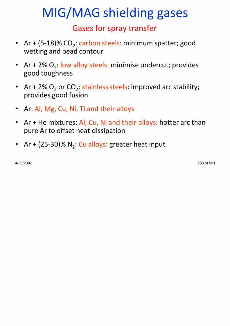
7/22/2019 weldinginspectioncswip-100402035204-phpapp02
http://slidepdf.com/reader/full/weldinginspectioncswip-100402035204-phpapp02 275/636
wetting and bead contour• Ar + 2% O2: low alloy steels: minimise undercut; provides
good toughness
• Ar + 2% O2 or CO2: stainless steels: improved arc stability;
provides good fusion
• Ar: Al, Mg, Cu, Ni, Ti and their alloys
• Ar + He mixtures: Al, Cu, Ni and their alloys: hotter arc than
pure Ar to offset heat dissipation• Ar + (25-30)% N2: Cu alloys: greater heat input
4/23/2007 293 of 691
Gas Metal Arc WeldingTypes of Shielding Gas
MAG (Metal Active Gas)

7/22/2019 weldinginspectioncswip-100402035204-phpapp02
http://slidepdf.com/reader/full/weldinginspectioncswip-100402035204-phpapp02 276/636
• Active gases used are Oxygen and Carbon Dioxide
• Argon with a small % of active gas is required for all steels
(including stainless steels) to ensure a stable arc & good
droplet wetting into the weld pool
• Typical active gases are
Ar + 20% CO2 for C-Mn & low alloy steels
Ar + 2% O2 for stainless steels
100% CO2 can be used for C - steels4/23/2007 294 of 691
MIG/MAG Gas Metal Arc Welding
Electrode
orientation

7/22/2019 weldinginspectioncswip-100402035204-phpapp02
http://slidepdf.com/reader/full/weldinginspectioncswip-100402035204-phpapp02 277/636
orientation
4/23/2007 295 of 691
Penetration Deep Moderate Shallow
Excess weld metal Maximum Moderate Minimum
Undercut Severe Moderate Minimum
Electrode extension
•Increased extension
MIG / MAG - self-regulating arc
Stable condition Sudden change in gun position
Arc length L = 6,4 mm
Arc voltage = 24V
Welding current = 250A
WFS = 6,4 m/min
Arc length L‟ = 12,7 mm
Arc voltage = 29V
Welding current = 220A
WFS = 6,4 m/min

7/22/2019 weldinginspectioncswip-100402035204-phpapp02
http://slidepdf.com/reader/full/weldinginspectioncswip-100402035204-phpapp02 278/636
4/23/2007 296 of 691
L19 mm
25 mmL‟
Melt off rate = 6,4 m/min Melt off rate = 5,6
m/min
Current (A)
V o l t a g e ( V )
MIG/MAG - self-regulating arcSudden change in gun position
Arc length L‟ = 12,7 mm
Arc voltage = 29V
Welding current = 220A
WFS = 6,4 m/min
M lt ff t 5 6 / i
Re-established stable condition
Arc length L = 6,4 mm
Arc voltage = 24V
Welding current = 250A
WFS = 6,4 m/min
M lt ff t 6 4 / i

7/22/2019 weldinginspectioncswip-100402035204-phpapp02
http://slidepdf.com/reader/full/weldinginspectioncswip-100402035204-phpapp02 279/636
4/23/2007 297 of 691
25 mmL‟
Melt off rate = 5,6 m/min
Current (A)
V o l t a g e ( V )
25 mmL
Melt off rate = 6,4 m/min
Terminating the arc
• Burnback time
– delayed current cut-off to prevent wire freeze
in the weld end crater
Crater fill

7/22/2019 weldinginspectioncswip-100402035204-phpapp02
http://slidepdf.com/reader/full/weldinginspectioncswip-100402035204-phpapp02 280/636
4/23/2007 298 of 691
in the weld end crater
– depends on WFS (set as short as possible!)
Contact tip
Workpiec
e
Burnback time 0.05 sec 0.10 sec 0.15 sec
14 mm
8 mm3 mm
Current - 250A
Voltage - 27V
WFS - 7,8 m/min
Wire diam. - 1,2 mmShielding gas -
Ar+18%CO2
Insulatin
g slag
MIG/MAG - metal transfer modes

7/22/2019 weldinginspectioncswip-100402035204-phpapp02
http://slidepdf.com/reader/full/weldinginspectioncswip-100402035204-phpapp02 281/636
Set-up for dip transfer Set-up for spray transfer
4/23/2007 299 of 691
Electrode
extension
19-25 mm
Contact tip
recessed
(3-5 mm)
Contact tip
extension
(0-3,2 mm)
Electrode
extension6-13 mm
MIG/MAG - metal transfer modes
VoltageElectrode diameter = 1,2 mm
WFS = 8,3 m/min
Current = 295 AV lt 28V

7/22/2019 weldinginspectioncswip-100402035204-phpapp02
http://slidepdf.com/reader/full/weldinginspectioncswip-100402035204-phpapp02 282/636
Current/voltage conditions4/23/2007 301 of 691
Current
Dip transfer
Spray
transfer
Globular
transfer
Electrode diameter = 1,2 mm
WFS = 3,2 m/min
Current = 145 A
Voltage = 18-20V
Voltage = 28V
MIG/MAG-methods of metal transfer
Dip transfer
Transfer occur due to short circuits
between wire and weld pool, high
level of spatter, need inductancecontrol to limit current raise

7/22/2019 weldinginspectioncswip-100402035204-phpapp02
http://slidepdf.com/reader/full/weldinginspectioncswip-100402035204-phpapp02 283/636
4/23/2007 303 of 691
pcontrol to limit current raise
Can use pure CO2 or Ar- CO2
mixtures as shielding gas
Metal transfer occur when arc isextinguished
Requires low welding current/arc
voltage, a low heat input process.
Resulting in low residual stress
and distortion
Used for thin materials and all
position welds
MIG/MAG-methods of metal transferSpray transfer
Transfer occur due to pincheffect NO contact between wire
and weld pool!

7/22/2019 weldinginspectioncswip-100402035204-phpapp02
http://slidepdf.com/reader/full/weldinginspectioncswip-100402035204-phpapp02 284/636
4/23/2007 306 of 691
Requires argon-rich shieldinggas
Metal transfer occur in small
droplets, a large volume weldpool
Requires high weldingcurrent/arc voltage, a high heatinput process. Resulting in highresidual stress and distortion
Used for thick materials andflat/horizontal position welds
MIG/MAG-methods of metal transferPulsed transfer
Controlled metal transfer, one droplet per pulse,
No transfer between droplet and weld pool!

7/22/2019 weldinginspectioncswip-100402035204-phpapp02
http://slidepdf.com/reader/full/weldinginspectioncswip-100402035204-phpapp02 285/636
4/23/2007 307 of 691
p p
Requires special power sources
Metal transfer occur in small droplets (diameter equal
to that of electrode)
Requires moderate welding current/arc voltage, a
reduced heat input . Resulting in smaller residual
stress and distortion compared to spray transfer
Pulse frequency controls the volume of weld pool,
used for root runs and out of position welds
MIG/MAG - metal transfer modes
Pulsed transfer
Controlled metal transfer. one dropletper pulse. NO transfer during

7/22/2019 weldinginspectioncswip-100402035204-phpapp02
http://slidepdf.com/reader/full/weldinginspectioncswip-100402035204-phpapp02 286/636
4/23/2007 308 of 691
pper pulse. NO transfer during
background current!
Requires special power sources
Metal transfer occur in small droplets(diameter equal to that of electrode)
Requires moderate welding current/arc voltage, reduced
heat input‟ smaller residual stress and distortions
compared to spray transfer
Pulse frequency controls the volume of weld pool, used
for root runs and out of position welds
MIG/MAG-methods of metal transfer
Globular transfer
Transfer occur due to gravity or
short circuits between drops andweld pool

7/22/2019 weldinginspectioncswip-100402035204-phpapp02
http://slidepdf.com/reader/full/weldinginspectioncswip-100402035204-phpapp02 287/636
4/23/2007 310 of 691
p
Requires CO2 shielding gas
Metal transfer occur in large drops
(diameter larger than that of
electrode) hence severe spatter Requires high welding current/arc
voltage, a high heat input process.
Resulting in high residual stress
and distortion
Non desired mode of transfer!
O.C.V. Arc Voltage
Flat or Constant Voltage Characteristic Used With
MIG/MAG, ESW & SAW < 1000 amps
Flat or Constant Voltage Characteristic
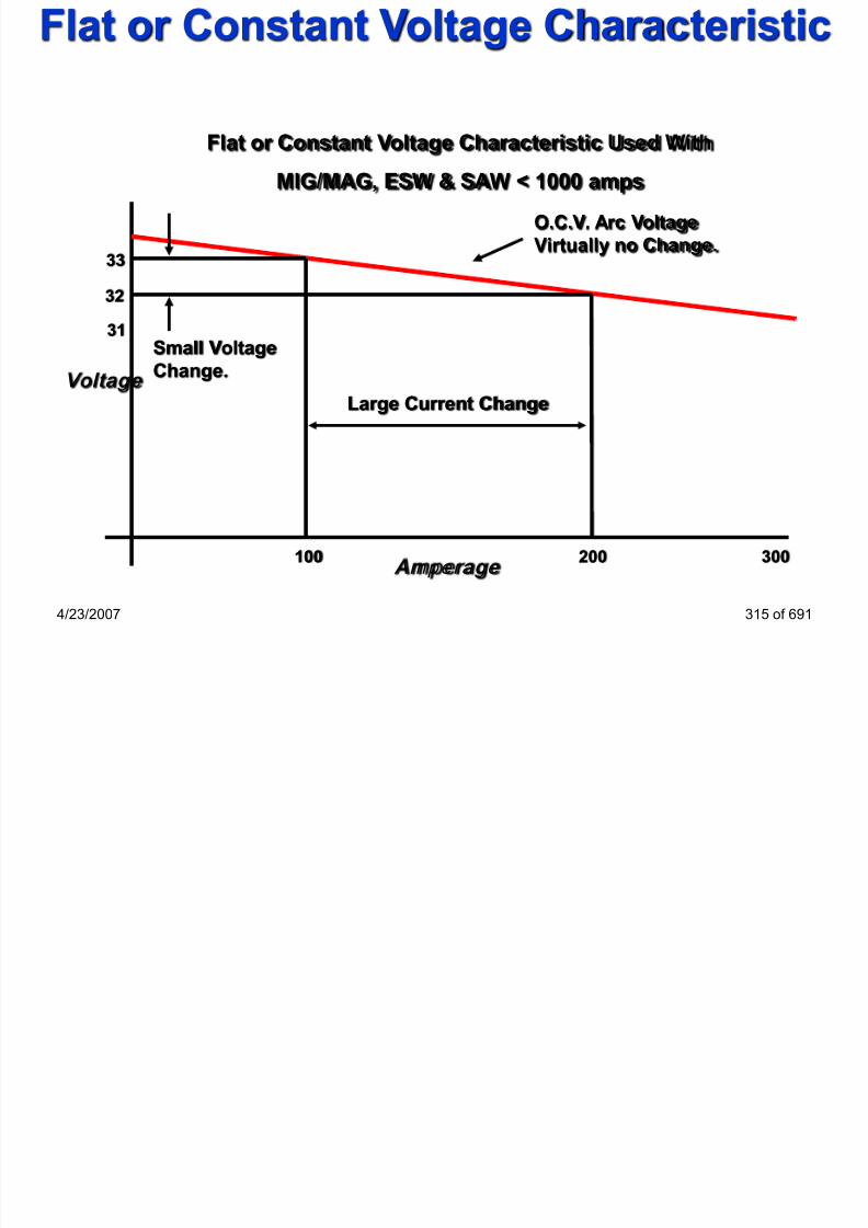
7/22/2019 weldinginspectioncswip-100402035204-phpapp02
http://slidepdf.com/reader/full/weldinginspectioncswip-100402035204-phpapp02 288/636
4/23/2007 315 of 691
g
Virtually no Change.
Voltage
100 200 300
33
32
31
Large Current Change
Small VoltageChange.
Amperage
MIG/MAG welding gun assembly
Contact
tip
Gas
diffuser The Push-Pull gun

7/22/2019 weldinginspectioncswip-100402035204-phpapp02
http://slidepdf.com/reader/full/weldinginspectioncswip-100402035204-phpapp02 289/636
4/23/2007 316 of 691
Handle
Gas
nozzle
Trigger WFS remote
control
potentiometer
Union nut
Gas Metal Arc WeldingPROCESS CHARACTERISTICS
• Requires a constant voltage power source, gas supply, wire
feeder, welding torch/gun and „hose package‟

7/22/2019 weldinginspectioncswip-100402035204-phpapp02
http://slidepdf.com/reader/full/weldinginspectioncswip-100402035204-phpapp02 290/636
4/23/2007 318 of 691
• Wire is fed continuously through the conduit and is burnt-off
at a rate that maintains a constant arc length/arc voltage
• Wire feed speed is directly related to burn-off rate
• Wire burn-off rate is directly related to current
• When the welder holds the welding gun the process is said
to be a semi-automatic process
• The process can be mechanised and also automated
• In Europe the process is usually called MIG or MAG
Most welding imperfections in MIG/MAG are caused by lack of
welder skill, or incorrect settings of the equipment
•Worn contact tips will cause poor power pick up, or transfer
MIG/MAG typical defects

7/22/2019 weldinginspectioncswip-100402035204-phpapp02
http://slidepdf.com/reader/full/weldinginspectioncswip-100402035204-phpapp02 291/636
4/23/2007 322 of 691
•Bad power connections will cause a loss of voltage in the arc
•Silica inclusions (in Fe steels) due to poor inter-run cleaning
•Lack of fusion (primarily with dip transfer)
•Porosity (from loss of gas shield on site etc)
•Solidification problems (cracking, centerline pipes, crater
pipes) especially on deep narrow welds
WELDING PROCESS
Flux Core Arc Welding

7/22/2019 weldinginspectioncswip-100402035204-phpapp02
http://slidepdf.com/reader/full/weldinginspectioncswip-100402035204-phpapp02 292/636
4/23/2007 323 of 691
Flux Core Arc Welding
(Not In The Training Manual)
Flux cored arc welding
FCAW
methods

7/22/2019 weldinginspectioncswip-100402035204-phpapp02
http://slidepdf.com/reader/full/weldinginspectioncswip-100402035204-phpapp02 293/636
4/23/2007 324 of 691
With gas
shielding -
“Outershield”
Without gas
shielding -
“Innershield”
With metal
powder -
“Metal core”
“Outershield” - principle of operation

7/22/2019 weldinginspectioncswip-100402035204-phpapp02
http://slidepdf.com/reader/full/weldinginspectioncswip-100402035204-phpapp02 294/636
4/23/2007 325 of 691
“Innershield” - principle of operation

7/22/2019 weldinginspectioncswip-100402035204-phpapp02
http://slidepdf.com/reader/full/weldinginspectioncswip-100402035204-phpapp02 295/636
4/23/2007 326 of 691
ARC CHARACTERISTICS
OCV
Constant Voltage Characteristic
Small change in voltage =large change in amperage

7/22/2019 weldinginspectioncswip-100402035204-phpapp02
http://slidepdf.com/reader/full/weldinginspectioncswip-100402035204-phpapp02 296/636
4/23/2007 327 of 691
Volts
Amps
g g p g
The selfadjusting arc.
Large arc gap
Small arc gap
Insulated extension nozzle
Current carrying guild tube
Flux core
Wire joint
Flux Core Arc Welding (FCAW)

7/22/2019 weldinginspectioncswip-100402035204-phpapp02
http://slidepdf.com/reader/full/weldinginspectioncswip-100402035204-phpapp02 297/636
4/23/2007 328 of 691
Flux cored hollow wire
Flux powder
Arc shield composed ofvaporized and slag formingcompounds
Metal droplets covered
with thin slag coating
Moltenweldpool
Solidified weldmetal and slag
Flux corewires
Flux cored arc weldingFCAW
methods

7/22/2019 weldinginspectioncswip-100402035204-phpapp02
http://slidepdf.com/reader/full/weldinginspectioncswip-100402035204-phpapp02 298/636
4/23/2007 329 of 691
With gas
shielding -
“Outershield”
Without gas
shielding -
“Innershield”
(114)
With metal
powder -
“Metal core”
With activegas shielding
(136)
With inert gasshielding (137)
FCAW - differences from MIG/MAG• usually operates in DCEP
but some “Innershield”wires operates in DCEN
• power sources need to bef l d h

7/22/2019 weldinginspectioncswip-100402035204-phpapp02
http://slidepdf.com/reader/full/weldinginspectioncswip-100402035204-phpapp02 299/636
more powerful due to thehigher currents
• doesn't work in deep
transfer mode• require knurled feed rolls
4/23/2007 330 of 691
“Innershield” wires use
a different type of
welding gun
Backhand (“drag”) technique
Advantages
preferred method for flat or horizontal position
slower progression of the weld

7/22/2019 weldinginspectioncswip-100402035204-phpapp02
http://slidepdf.com/reader/full/weldinginspectioncswip-100402035204-phpapp02 300/636
4/23/2007 331 of 691
p g
deeper penetration
weld stays hot longer, easy to remove dissolved
gassesDisadvantages
produce a higher weld profile
difficult to follow the weld jointcan lead to burn-through on thin sheet plates
Forehand (“push”) techniqueAdvantages
preferred method for vertical up or overhead
positionarc is directed towards the unwelded joint , preheat

7/22/2019 weldinginspectioncswip-100402035204-phpapp02
http://slidepdf.com/reader/full/weldinginspectioncswip-100402035204-phpapp02 301/636
4/23/2007 332 of 691
arc is directed towards the unwelded joint , preheat
effect
easy to follow the weld joint and control the
penetrationDisadvantages
produce a low weld profile, with coarser ripples
fast weld progression, shallower depth of penetration
the amount of spatter can increase
FCAW advantages• less sensitive to lack of fusion
• requires smaller included angle compared to MMA
• high productivity

7/22/2019 weldinginspectioncswip-100402035204-phpapp02
http://slidepdf.com/reader/full/weldinginspectioncswip-100402035204-phpapp02 302/636
• all positional
• smooth bead surface, less danger of undercut
• basic types produce excellent toughness properties
• good control of the weld pool in positional welding especially
with rutile wires
• seamless wires have no torsional strain, twist free
• ease of varying the alloying constituents• no need for shielding gas
4/23/2007 333 of 691
FCAW disadvantages• limited to steels and Ni-base alloys
• slag covering must be removed
• FCAW wire is more expensive on a weight basis than solid
wires (exception: some high alloy steels)

7/22/2019 weldinginspectioncswip-100402035204-phpapp02
http://slidepdf.com/reader/full/weldinginspectioncswip-100402035204-phpapp02 303/636
• for gas shielded process, the gaseous shield may be
affected by winds and drafts
• more smoke and fumes are generated compared with
MIG/MAG
• in case of Innershield wires, it might be necessary to
break the wire for restart (due to the high amount of
insulating slag formed at the tip of the wire)
4/23/2007 334 of 691
Advantages:
1) Field or shop use
Disadvantages:
1) High skill factor 2) Sl i l i
FCAW advantages/disadvantages

7/22/2019 weldinginspectioncswip-100402035204-phpapp02
http://slidepdf.com/reader/full/weldinginspectioncswip-100402035204-phpapp02 304/636
4/23/2007 335 of 691
2) High productivity
3) All positional
4) Slag supports and
shapes the weld Bead
5) No need for shielding
gas
2) Slag inclusions
3) Cored wire is
Expensive
4) High level of fume
(Inner-shield)
5) Limited to steels andnickel alloys
Welding Inspector
Submerged Arc Welding
Section 13

7/22/2019 weldinginspectioncswip-100402035204-phpapp02
http://slidepdf.com/reader/full/weldinginspectioncswip-100402035204-phpapp02 305/636
Section 13
4/23/2007 336 of 691
• Submerged arc welding was developed in the Soviet Union
during the 2nd world war for the welding of thick section steel.
• The process is normally mechanized.
• The process uses amps in the range of 100 to over2000 which
Submerged Arc Welding Introduction

7/22/2019 weldinginspectioncswip-100402035204-phpapp02
http://slidepdf.com/reader/full/weldinginspectioncswip-100402035204-phpapp02 306/636
4/23/2007 337 of 691
• The process uses amps in the range of 100 to over2000, which
gives a very high current density in the wire producing deep
penetration and high dilution welds.
• A flux is supplied separately via a flux hopper in the form of eitherfused or agglomerated.
• The arc is not visible as it is submerged beneath the flux layer
and no eye protection is required.
SAW Principle of operation

7/22/2019 weldinginspectioncswip-100402035204-phpapp02
http://slidepdf.com/reader/full/weldinginspectioncswip-100402035204-phpapp02 307/636
4/23/2007 338 of 691
Principles of operationFactors that determine whether to use SAW chemical
composition and mechanical properties required for the weld
deposit
• thickness of base metal to be welded
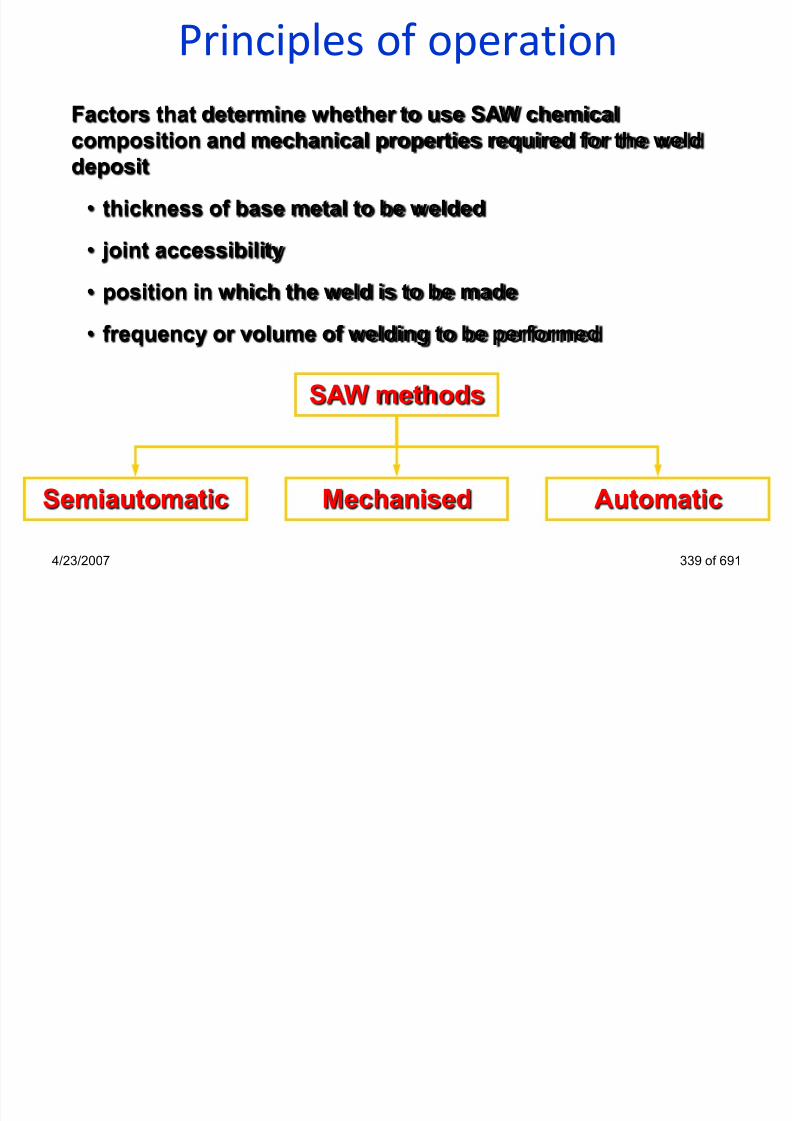
7/22/2019 weldinginspectioncswip-100402035204-phpapp02
http://slidepdf.com/reader/full/weldinginspectioncswip-100402035204-phpapp02 308/636
4/23/2007 339 of 691
• joint accessibility
• position in which the weld is to be made
• frequency or volume of welding to be performed
SAW methods
Semiautomatic Mechanised Automatic
Submerged Arc Welding
Power
supply
Filler wire spool
Flux hopper

7/22/2019 weldinginspectioncswip-100402035204-phpapp02
http://slidepdf.com/reader/full/weldinginspectioncswip-100402035204-phpapp02 309/636
4/23/2007 340 of 691
- +
Wire electrode
Flux
Slide rail
SAW process variables• welding current
• current type and polarity
• welding voltage• travel speed

7/22/2019 weldinginspectioncswip-100402035204-phpapp02
http://slidepdf.com/reader/full/weldinginspectioncswip-100402035204-phpapp02 310/636
4/23/2007 341 of 691
travel speed
• electrode size
• electrode extension
• width and depth of the layer of flux
SAW process variablesWelding current
•controls depth of penetration and the amount of
base metal melted & dilution

7/22/2019 weldinginspectioncswip-100402035204-phpapp02
http://slidepdf.com/reader/full/weldinginspectioncswip-100402035204-phpapp02 311/636
4/23/2007 342 of 691
SAW operating variablesCurrent type and polarity
•Usually DCEP, deep
penetration, better
i t t

7/22/2019 weldinginspectioncswip-100402035204-phpapp02
http://slidepdf.com/reader/full/weldinginspectioncswip-100402035204-phpapp02 312/636
4/23/2007 343 of 691
resistance to
porosity
•DCEN increase
deposition rate but
reduce penetration
(surfacing)
•AC used to avoidarc blow; can give
unstable arc
SAW Consumables(Covered in detail in Section 14)
Fused fluxes advantages:
•good chemical homogeneity
•easy removal of fines without affecting fluxcomposition

7/22/2019 weldinginspectioncswip-100402035204-phpapp02
http://slidepdf.com/reader/full/weldinginspectioncswip-100402035204-phpapp02 313/636
4/23/2007 344 of 691
•normally not hygroscopic & easy storage and handling
•readily recycled without significant change in particle
size or composition
Fused fluxes disadvantages:•difficult to add deoxidizers and ferro-alloys (due to
segregation or extremely high loss)
•high temperatures needed to melt ingredients limit the
range of flux compositions
SAW ConsumablesAgglomerated fluxes advantages:
• easy addition of deoxidizers and alloying elements
• usable with thicker layer of flux when welding
l id ifi i

7/22/2019 weldinginspectioncswip-100402035204-phpapp02
http://slidepdf.com/reader/full/weldinginspectioncswip-100402035204-phpapp02 314/636
4/23/2007 345 of 691
• colour identification
Agglomerated fluxes disadvantages:
• tendency to absorb moisture
• possible gas evolution from the molten slag leading to
porosity
• possible change in flux composition due to segregation orremoval of fine mesh particles
SAW equipmentPower sources can be:
• transformers for AC
• transformer-rectifiers for DC
St ti h t i ti b
7/22/2019 weldinginspectioncswip-100402035204-phpapp02
http://slidepdf.com/reader/full/weldinginspectioncswip-100402035204-phpapp02 315/636
4/23/2007 346 of 691
Static characteristic can be:
• Constant Voltage (flat) - most of the power sources
• Constant Current (drooping)
SAW equipmentConstant Voltage (Flat Characteristic) power sources:
• most commonly used supplies for SAW
• can be used for both semiautomatic and automatic welding
lf l ti

7/22/2019 weldinginspectioncswip-100402035204-phpapp02
http://slidepdf.com/reader/full/weldinginspectioncswip-100402035204-phpapp02 316/636
4/23/2007 347 of 691
• self-regulating arc
• simple wire feed speed control
• wire feed speed controls the current and power supplycontrols the voltage
• applications for DC are limited to 1000A due to severe arc
blow (also thin wires!)
ARC CHARACTERISTICS
OCV
Constant Voltage Characteristic
Small change in voltage =large change in amperage
Large arc gap

7/22/2019 weldinginspectioncswip-100402035204-phpapp02
http://slidepdf.com/reader/full/weldinginspectioncswip-100402035204-phpapp02 317/636
4/23/2007 348 of 691
Volts
Amps
The selfadjusting arc.
Large arc gap
Small arc gap
SAW equipmentConstant Current (Drooping Characteristic) power sources:
• Over 1000A - very fast speed required - control of burn off
rate and stick out length
• can be used for both semiautomatic and automatic welding

7/22/2019 weldinginspectioncswip-100402035204-phpapp02
http://slidepdf.com/reader/full/weldinginspectioncswip-100402035204-phpapp02 318/636
4/23/2007 349 of 691
• not self-regulating arc
• must be used with a voltage-sensing variable wire feed
speed control• more expensive due to more complex wire feed speed
control
• arc voltage depends upon wire feed speed whilst the power
source controls the current• cannot be used for high-speed welding of thin steel
SAW equipmentWelding heads can be mounted on a:
Tractor type carriage
• provides travel along straight orgently curved joints

7/22/2019 weldinginspectioncswip-100402035204-phpapp02
http://slidepdf.com/reader/full/weldinginspectioncswip-100402035204-phpapp02 319/636
4/23/2007 350 of 691
• can ride on tracks set up along the
joint (with grooved wheels) or on
the workpiece itself
• can use guide wheels as tracking
device
• due to their portability, are used in
field welding or where the piece
cannot be moved
Courtesy of ESAB AB
Courtesy of ESAB AB
SAW operating variablesWelding current
•too high current: excessive excess weld metal
(waste of electrode), increase weld shrinkage and
causes greater distortions
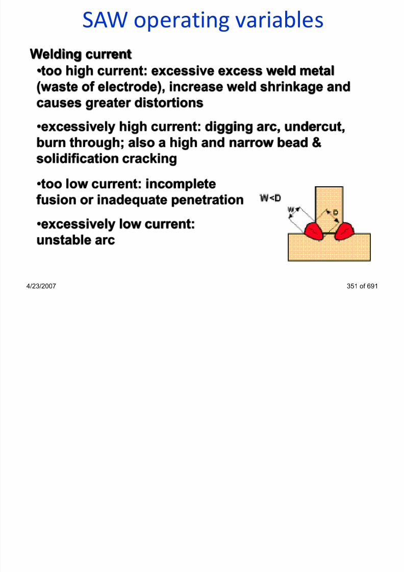
7/22/2019 weldinginspectioncswip-100402035204-phpapp02
http://slidepdf.com/reader/full/weldinginspectioncswip-100402035204-phpapp02 320/636
4/23/2007 351 of 691
•excessively high current: digging arc, undercut,
burn through; also a high and narrow bead &
solidification cracking
•too low current: incomplete
fusion or inadequate penetration
•excessively low current:
unstable arc
SAW operating variablesWelding voltage
•welding voltage controls arc
length
•increase in voltage produce a
flatter and wider bead

7/22/2019 weldinginspectioncswip-100402035204-phpapp02
http://slidepdf.com/reader/full/weldinginspectioncswip-100402035204-phpapp02 321/636
4/23/2007 352 of 691
•an increased voltage can increase pick-up of alloying elements
from an alloy flux
flatter and wider bead
•increase in voltage increase
flux consumption
•increase in voltage tend toreduce porosity
•an increased voltage may
help bridging an excessive
root gap
SAW operating variables
Welding voltage
•low voltage produce a“stiffer” arc & improves

7/22/2019 weldinginspectioncswip-100402035204-phpapp02
http://slidepdf.com/reader/full/weldinginspectioncswip-100402035204-phpapp02 322/636
4/23/2007 353 of 691
& p
penetration in a deep
weld groove and resists
arc blow•excessive low voltage
produce a high narrow
bead & difficult slag
removal
SAW operating variablesWelding voltage
•excessively high voltageproduce a “hat-shaped” bead
& tendency to crack

7/22/2019 weldinginspectioncswip-100402035204-phpapp02
http://slidepdf.com/reader/full/weldinginspectioncswip-100402035204-phpapp02 323/636
4/23/2007 354 of 691
& tendency to crack
•excessively high voltage
increase undercut & make slagremoval difficult in groove
welds
•excessively high voltageproduce a concave fillet weld
that is subject to cracking
SAW operating variablesTravel speed
•increase in travel speed: decrease heat input & less
filler metal applied per unit of length, less excessweld metal & weld bead becomes smaller

7/22/2019 weldinginspectioncswip-100402035204-phpapp02
http://slidepdf.com/reader/full/weldinginspectioncswip-100402035204-phpapp02 324/636
4/23/2007 355 of 691
SAW operating variablesTravel speed
•excessively high speed
lead to undercut, arcblow and porosity

7/22/2019 weldinginspectioncswip-100402035204-phpapp02
http://slidepdf.com/reader/full/weldinginspectioncswip-100402035204-phpapp02 325/636
4/23/2007 356 of 691
p y
•excessively low speedproduce “hat-shaped” beads
danger of cracking
•excessively low speed produce rough beads andlead to slag inclusions
SAW operating variablesElectrode size
•at the same current, small electrodes have higher
current density & higher deposition rates

7/22/2019 weldinginspectioncswip-100402035204-phpapp02
http://slidepdf.com/reader/full/weldinginspectioncswip-100402035204-phpapp02 326/636
4/23/2007 357 of 691
SAW operating variablesElectrode extension
•increased electrode extension adds resistance in the
welding circuit I increase in deposition rate, decrease in
penetration and bead width

7/22/2019 weldinginspectioncswip-100402035204-phpapp02
http://slidepdf.com/reader/full/weldinginspectioncswip-100402035204-phpapp02 327/636
4/23/2007 358 of 691
•to keep a proper weld shape, when electrode extension is
increased, voltage must also be increased
•when burn-through is a problem (e.g. thin gauge), increase
electrode extension
•excessive electrode extension: it is more difficult to
maintain the electrode tip in the correct position
SAW operating variablesDepth of flux
•depth of flux layer influence the appearance of weld
•usually, depth of flux is 25-30 mm

7/22/2019 weldinginspectioncswip-100402035204-phpapp02
http://slidepdf.com/reader/full/weldinginspectioncswip-100402035204-phpapp02 328/636
4/23/2007 359 of 691
•if flux layer is to deep the arc is too confined, result is
a rough ropelike appearing weld
•if flux layer is to deep the gases cannot escape & thesurface of molten weld metal becomes irregularly
distorted
•if flux layer is too shallow, flashing and spattering will
occur, give a poor appearance and porous weld
SAW technological variablesTravel angle effect - Butt weld on plates

7/22/2019 weldinginspectioncswip-100402035204-phpapp02
http://slidepdf.com/reader/full/weldinginspectioncswip-100402035204-phpapp02 329/636
4/23/2007 363 of 691
Penetration Deep Moderate ShallowExcess weld metal Maximum Moderate Minimum
Tendency to undercut Severe Moderate Minimum
SAW technological variablesEarth position +
Direction of
travel

7/22/2019 weldinginspectioncswip-100402035204-phpapp02
http://slidepdf.com/reader/full/weldinginspectioncswip-100402035204-phpapp02 330/636
4/23/2007 364 of 691
-
•welding towards earth produces backward arc blow
•deep penetration
•convex weld profile
SAW technological variablesEarth position
+
Direction oftravel

7/22/2019 weldinginspectioncswip-100402035204-phpapp02
http://slidepdf.com/reader/full/weldinginspectioncswip-100402035204-phpapp02 331/636
4/23/2007 365 of 691
-
•welding away earth produces forward arc blow
•normal penetration depth
•smooth, even weld profile
Weld backing
Backing strip

7/22/2019 weldinginspectioncswip-100402035204-phpapp02
http://slidepdf.com/reader/full/weldinginspectioncswip-100402035204-phpapp02 332/636
4/23/2007 366 of 691
Backing weld
Copper backing
Starting/finishing the weld

7/22/2019 weldinginspectioncswip-100402035204-phpapp02
http://slidepdf.com/reader/full/weldinginspectioncswip-100402035204-phpapp02 333/636
4/23/2007 367 of 691
SAW variants
Twin wire SAW welding •two electrodes are feed
into the same weld pool
•wire diameter usually 1,6 to3,2 mm

7/22/2019 weldinginspectioncswip-100402035204-phpapp02
http://slidepdf.com/reader/full/weldinginspectioncswip-100402035204-phpapp02 334/636
4/23/2007 368 of 691
•electrodes are connected
to a single power source & a
single arc is established
•normally operate with
DCEP
•offers increased depositionrate by up to 80% compared
to single wire SAW
SAW variants

7/22/2019 weldinginspectioncswip-100402035204-phpapp02
http://slidepdf.com/reader/full/weldinginspectioncswip-100402035204-phpapp02 335/636
4/23/2007 369 of 691
Wires can be oriented
for maximum or
minimum penetration
SAW variantsTandem arc SAW process •usually DCEP on lead
and AC on trail to reduce
arc blow•requires two separate

7/22/2019 weldinginspectioncswip-100402035204-phpapp02
http://slidepdf.com/reader/full/weldinginspectioncswip-100402035204-phpapp02 336/636
4/23/2007 370 of 691
power sources
•the electrodes are active
in the same puddle BUTthere are 2 separate arcs
•increased deposition
rate by up to 100%
compared with single
wire SAW
SAW variantsSAW tandem arc
with two wires

7/22/2019 weldinginspectioncswip-100402035204-phpapp02
http://slidepdf.com/reader/full/weldinginspectioncswip-100402035204-phpapp02 337/636
4/23/2007 371 of 691
Courtesy of ESAB AB
SAW variants

7/22/2019 weldinginspectioncswip-100402035204-phpapp02
http://slidepdf.com/reader/full/weldinginspectioncswip-100402035204-phpapp02 338/636
4/23/2007 372 of 691
Single pool - highest deposition rate
Twin pool - travel speed limited by undercut;
very resistant to porosity and cracks
SAW variants
Tandem arc SAW process - multiple wires
•only for welding thick
sections (>30 mm)
•not suitable for use in

7/22/2019 weldinginspectioncswip-100402035204-phpapp02
http://slidepdf.com/reader/full/weldinginspectioncswip-100402035204-phpapp02 339/636
4/23/2007 373 of 691
•not suitable for use in
narrow weld
preparations (root
passes)
•one 4 mm wire at 600 A,
6.8 kg/hr
•tandem two 4 mm wiresat 600 A, 13.6 kg/hr Courtesy of ESAB AB
SAW variantsStrip cladding needs a
special welding head

7/22/2019 weldinginspectioncswip-100402035204-phpapp02
http://slidepdf.com/reader/full/weldinginspectioncswip-100402035204-phpapp02 340/636
4/23/2007 374 of 691
SAW variantsNarrow gap welding
•for welding thick
materials
•less filler metal required

7/22/2019 weldinginspectioncswip-100402035204-phpapp02
http://slidepdf.com/reader/full/weldinginspectioncswip-100402035204-phpapp02 341/636
4/23/2007 375 of 691
•requires special groove
preparation and special
welding head•requires special fluxes,
otherwise problems with
slag removal
•defect removal is verydifficult
SAW variantsHot wire welding
•the hot wire is connected to power source & much
more efficient than cold wire (current is used entirelyto heat the wire!)
i d iti t

7/22/2019 weldinginspectioncswip-100402035204-phpapp02
http://slidepdf.com/reader/full/weldinginspectioncswip-100402035204-phpapp02 342/636
4/23/2007 377 of 691
•increase deposition rates
up to 100%
•requires additionalwelding equipment,
additional control of
variables, considerable
set-up time and closeroperator attention
SAW variants
SAW with metal powder addition
•increased deposition rates up to70%; increased welding speed
•gives smooth fusion, improvedbead appearance, reduced
i d dil i f

7/22/2019 weldinginspectioncswip-100402035204-phpapp02
http://slidepdf.com/reader/full/weldinginspectioncswip-100402035204-phpapp02 343/636
4/23/2007 378 of 691
penetration and dilution from parentmetal & higher impact strength
•metal powders can modifychemical composition of final welddeposit
•does not increase risk of cracking
•do not require additional arc energy
•metal powder can be added aheador directly into the weld pool
SAW variants
SAW with metal powder addition
•magnetic attachment of powder

7/22/2019 weldinginspectioncswip-100402035204-phpapp02
http://slidepdf.com/reader/full/weldinginspectioncswip-100402035204-phpapp02 344/636
4/23/2007 379 of 691
•SAW with metal cored wires
SAW variantsStorage tank
SAW of circular
welds
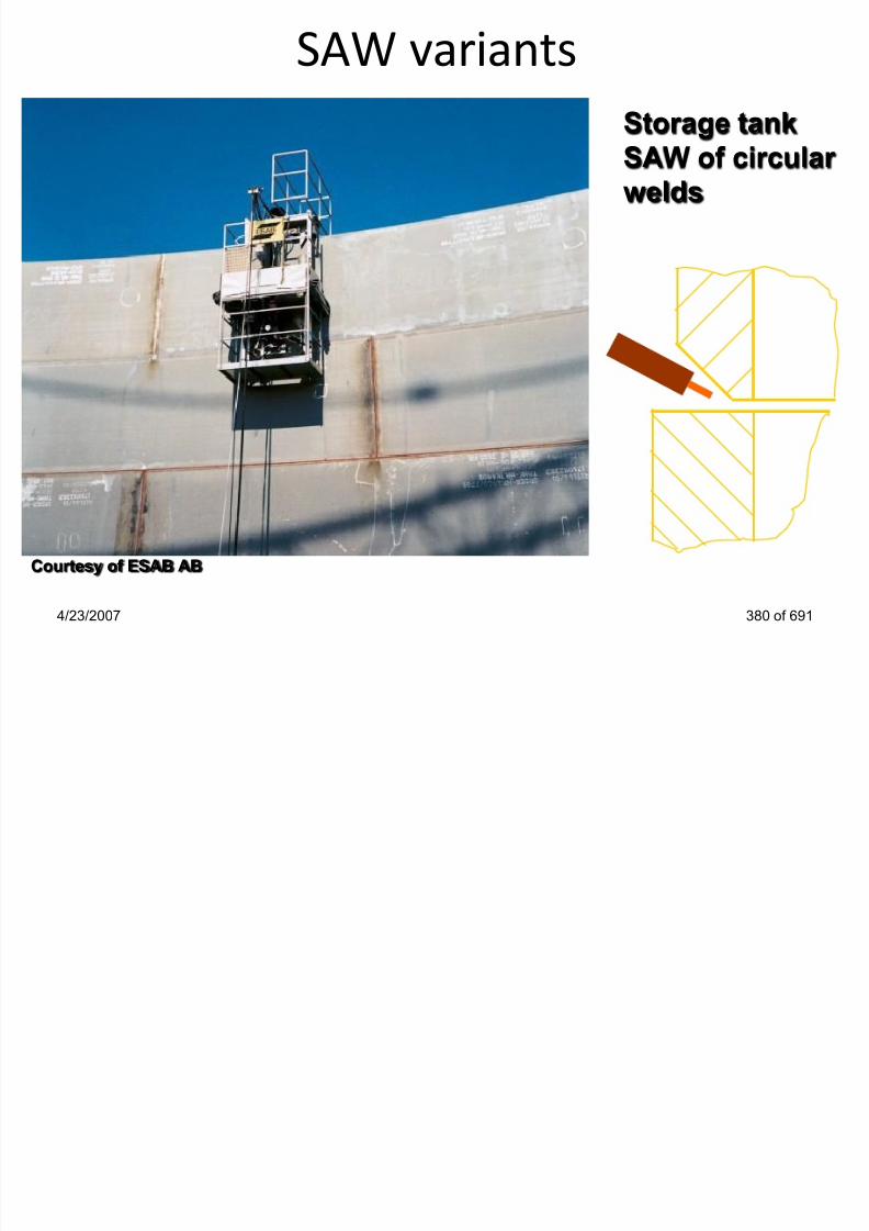
7/22/2019 weldinginspectioncswip-100402035204-phpapp02
http://slidepdf.com/reader/full/weldinginspectioncswip-100402035204-phpapp02 345/636
4/23/2007 380 of 691
Courtesy of ESAB AB
Advantages of SAW• high current density, high deposition rates (up to 10 times
those for MMA), high productivity
• deep penetration allowing the use of small welding grooves
• fast travel speed, less distortion
• deslagging is easier

7/22/2019 weldinginspectioncswip-100402035204-phpapp02
http://slidepdf.com/reader/full/weldinginspectioncswip-100402035204-phpapp02 346/636
4/23/2007 382 of 691
• uniform bead appearance with good surface finish and good
fatigue properties
• can be easily performed mechanised, giving a higher dutycycle and low skill level required
• provide consistent quality when performed automatic or
mechanised
• Virtually assured radiographically sound welds
• arc is not visible
• little smoke/fumes are developed
Advantages
• Low weld-metal cost
• Easily automated
Disadvantages
• Restricted weldingpositions
Submerged Arc Welding

7/22/2019 weldinginspectioncswip-100402035204-phpapp02
http://slidepdf.com/reader/full/weldinginspectioncswip-100402035204-phpapp02 347/636
4/23/2007 384 of 691
y
• Low levels of ozone
• High productivity
• No visible arc light
• Minimum cleaning
• Arc blow on DC
current
• Shrinkage defects
• Difficult penetration
control
• Limited joints
Welding Inspector
Welding Consumables
Section 14

7/22/2019 weldinginspectioncswip-100402035204-phpapp02
http://slidepdf.com/reader/full/weldinginspectioncswip-100402035204-phpapp02 348/636
4/23/2007 385 of 691
BS EN 499 MMA Covered Electrodes
Covered Electrode
Toughness
Yield Strength N/mm2
E 50 3 2Ni B 7 2 H10

7/22/2019 weldinginspectioncswip-100402035204-phpapp02
http://slidepdf.com/reader/full/weldinginspectioncswip-100402035204-phpapp02 349/636
4/23/2007 386 of 691
Toughness
Chemical composition
Flux Covering
Weld Metal Recovery
and Current Type
Welding Position
Hydrogen Content
Welding consumables are any products that are used up in
the production of a weld
Welding consumables may be:• Covered electrodes, filler wires and electrode wires.
Welding consumables

7/22/2019 weldinginspectioncswip-100402035204-phpapp02
http://slidepdf.com/reader/full/weldinginspectioncswip-100402035204-phpapp02 350/636
4/23/2007 387 of 691
• Shielding or oxy-fuel gases.
• Separately supplied fluxes.
• Fusible inserts.
Welding Consumable Standards
MMA (SMAW)
• BS EN 499: Steel electrodes
• AWS A5.1 Non-alloyed steel
MIG/MAG (GMAW) TIG (GTAW)
• BS 2901: Filler wires
• BS EN 440: Wire electrodes
• AWS A5.9: Filler wires
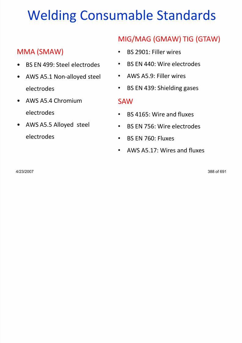
7/22/2019 weldinginspectioncswip-100402035204-phpapp02
http://slidepdf.com/reader/full/weldinginspectioncswip-100402035204-phpapp02 351/636
y
electrodes
• AWS A5.4 Chromiumelectrodes
• AWS A5.5 Alloyed steel
electrodes
• BS EN 439: Shielding gases
SAW• BS 4165: Wire and fluxes
• BS EN 756: Wire electrodes
• BS EN 760: Fluxes
• AWS A5.17: Wires and fluxes
4/23/2007 388 of 691
Welding Consumable Gases
welding gases
• GMAW, FCAW, TIG, Oxy- Fuel
• Supplied in cylinders or storage
tanks for large quantities
• Colour coded cylinders to minimisewrong use

7/22/2019 weldinginspectioncswip-100402035204-phpapp02
http://slidepdf.com/reader/full/weldinginspectioncswip-100402035204-phpapp02 352/636
4/23/2007 389 of 691
wrong use
• Subject to regulations concernedhandling, quantities and positioning
of storage areas• Moisture content is limited to avoid
cold cracking
• Dew point (the temperature at whichthe vapour begins to condense)must be checked
Welding ConsumablesEach consumable is critical in respect to:
• Size, (diameter and length)
• Classification / Supplier
C di i

7/22/2019 weldinginspectioncswip-100402035204-phpapp02
http://slidepdf.com/reader/full/weldinginspectioncswip-100402035204-phpapp02 353/636
• Condition
• Treatments e.g. baking / drying
• Handling and storage is critical for consumable control
• Handling and storage of gases is critical for safety
4/23/2007 390 of 691
MMA Welding Consumables
MMA Covered Electrodes

7/22/2019 weldinginspectioncswip-100402035204-phpapp02
http://slidepdf.com/reader/full/weldinginspectioncswip-100402035204-phpapp02 354/636
4/23/2007 392 of 691
The three main electrode covering types used in MMA welding
• Cellulosic - deep penetration/fusion
• Rutile - general purpose
• Basic - low hydrogen
MMA Welding ConsumablesWelding consumables for MMA:
• Consist of a core wire typically between 350-450mm in length
and from 2.5mm - 6mm in diameter
Th i i d ith t d d fl ti

7/22/2019 weldinginspectioncswip-100402035204-phpapp02
http://slidepdf.com/reader/full/weldinginspectioncswip-100402035204-phpapp02 355/636
• The wire is covered with an extruded flux coating
• The core wire is generally of a low quality rimming steel
• The weld quality is refined by the addition of alloying and
refining agents in the flux coating
• The flux coating contains many elements and compounds
that all have a variety of functions during welding
4/23/2007 393 of 691
MMA Welding ConsumablesFunction of the Electrode Covering:
• To facilitate arc ignition and give arc stability
• To generate gas for shielding the arc & molten metal from aircontamination
• To de-oxidise the weld metal and flux impurities into the slag

7/22/2019 weldinginspectioncswip-100402035204-phpapp02
http://slidepdf.com/reader/full/weldinginspectioncswip-100402035204-phpapp02 356/636
4/23/2007 394 of 691
To de oxidise the weld metal and flux impurities into the slag
• To form a protective slag blanket over the solidifying andcooling weld metal
• To provide alloying elements to give the required weld metalproperties
• To aid positional welding (slag design to have suitablefreezing temperature to support the molten weld metal)
• To control hydrogen contents in the weld (basic type)
1: Electrode size (diameter and length)
2: Covering condition: adherence, cracks, chips and concentricity
Covered electrode inspection

7/22/2019 weldinginspectioncswip-100402035204-phpapp02
http://slidepdf.com/reader/full/weldinginspectioncswip-100402035204-phpapp02 357/636
4/23/2007 395 of 691
3: Electrode designation
EN 499-E 51 3 B
Arc ignition enhancing materials (optional!)
See BS EN ISO 544 for further information
MMA Welding Consumables
Plastic foil sealed cardboard box•rutile electrodes
•general purpose basic electrodes
Courtesy of Lincoln Electric c

7/22/2019 weldinginspectioncswip-100402035204-phpapp02
http://slidepdf.com/reader/full/weldinginspectioncswip-100402035204-phpapp02 358/636
4/23/2007 396 of 691
Tin can
•cellulosic electrodes
Vacuum sealed pack
•extra low hydrogen electrodes
Courtesy of Lincoln Electric
C o u r t e s y o f L i n c o l n E l e c t r i c
MMA Welding ConsumablesCellulosic electrodes:
• covering contains cellulose (organic material).
• produce a gas shield high in hydrogen raising the arcvoltage.
D i / f i h i i bl ldi

7/22/2019 weldinginspectioncswip-100402035204-phpapp02
http://slidepdf.com/reader/full/weldinginspectioncswip-100402035204-phpapp02 359/636
• Deep penetration / fusion characteristics enables welding
at high speed without risk of lack of fusion.
• generates high level of fumes and H2 cold cracking.
• Forms a thin slag layer with coarse weld profile.
• not require baking or drying (excessive heat will damage
electrode covering!).
• Mainly used for stove pipe welding
• hydrogen content is 80-90 ml/100 g of weld metal.4/23/2007 397 of 691
MMA Welding ConsumablesCellulosic Electrodes
Disadvantages:
• weld beads have high hydrogen
• risk of cracking (need to keep joint hot during welding to allow

7/22/2019 weldinginspectioncswip-100402035204-phpapp02
http://slidepdf.com/reader/full/weldinginspectioncswip-100402035204-phpapp02 360/636
4/23/2007 398 of 691
g ( p j g g
H to escape)
• not suitable for higher strength steels - cracking risk too
high (may not be allowed for Grades stronger than X70)
• not suitable for very thick sections (may not be used on
thicknesses > ~ 35mm)
• not suitable when low temperature toughness is required
(impact toughness satisfactory down to ~ -20 ° C)
MMA Welding Consumables
Advantages:
• Deep penetration/fusion
Disadvantages:
• High in hydrogen
Cellulosic Electrodes

7/22/2019 weldinginspectioncswip-100402035204-phpapp02
http://slidepdf.com/reader/full/weldinginspectioncswip-100402035204-phpapp02 361/636
• Suitable for welding in all
positions
• Fast travel speeds
• Large volumes of shielding gas
• Low control
• High crack tendency
• Rough weld appearance
• High spatter contents
• Low deposition rates
4/23/2007 399 of 691
MMA Welding Consumables
Rutile electrodes:
• covering contains TiO2 slag former and arc stabiliser.
• easy to strike arc, less spatter, excellent for positional
welding.
• stable, easy-to-use arc can operate in both DC and AC.

7/22/2019 weldinginspectioncswip-100402035204-phpapp02
http://slidepdf.com/reader/full/weldinginspectioncswip-100402035204-phpapp02 362/636
4/23/2007 400 of 691
• slag easy to detach, smooth profile.
• Reasonably good strength weld metal.
• Used mainly on general purpose work.
• Low pressure pipework, support brackets.
• electrodes can be dried to lower H2 content but cannot be
baked as it will destroy the coating.
• hydrogen content is 25-30 ml/100 g of weld metal.
MMA Welding ConsumablesRutile electrodes
Disadvantages:
• they cannot be made with a low hydrogen content
• cannot be used on high strength steels or thick joints -

7/22/2019 weldinginspectioncswip-100402035204-phpapp02
http://slidepdf.com/reader/full/weldinginspectioncswip-100402035204-phpapp02 363/636
4/23/2007 401 of 691
cracking risk too high
• they do not give good toughness at low temperatures
• these limitations mean that they are only suitable for general
engineering - low strength, thin steel
MMA Welding Consumables
Advantages:
• Easy to use
• Low cost / control
Disadvantages:
• High in hydrogen
• High crack tendency
Rutile Electrodes

7/22/2019 weldinginspectioncswip-100402035204-phpapp02
http://slidepdf.com/reader/full/weldinginspectioncswip-100402035204-phpapp02 364/636
Low cost / control
• Smooth weld profiles
• Slag easily detachable
• High deposition possible
with the addition of iron
powder
High crack tendency
• Low strength
• Low toughness values
4/23/2007 402 of 691
MMA Welding ConsumablesRutile Variants
High Recovery Rutile Electrodes
Characteristics:
• coating is „bulked out‟ with iron powder
• iron powder gives the electrode „high recovery‟

7/22/2019 weldinginspectioncswip-100402035204-phpapp02
http://slidepdf.com/reader/full/weldinginspectioncswip-100402035204-phpapp02 365/636
4/23/2007 403 of 691
• extra weld metal from the iron powder can mean that weld
deposit from a single electrode can be as high as 180% of
the core wire weight
• give good productivity
• large weld beads with smooth profile can look very similar to
SAW welds
MMA Welding ConsumablesHigh Recovery Rutile Electrodes
Disadvantages:
• Same as standard rutile electrodes with respect to hydrogen
control

7/22/2019 weldinginspectioncswip-100402035204-phpapp02
http://slidepdf.com/reader/full/weldinginspectioncswip-100402035204-phpapp02 366/636
4/23/2007 404 of 691
• large weld beads produced cannot be used for all-positional
welding
• the very high recovery types usually limited to PA & PB
positions
• more moderate recovery may allow PC use
MMA Welding Consumables
Basic covering:
• Produce convex weld profile and difficult to detach slag.
• Very suitable for for high pressure work, thick section steeland for high strength steels.
• Prior to use electrodes should be baked, typically 350°C for 2h l d i l l l d hi

7/22/2019 weldinginspectioncswip-100402035204-phpapp02
http://slidepdf.com/reader/full/weldinginspectioncswip-100402035204-phpapp02 367/636
4/23/2007 405 of 691
hour plus to reduce moisture to very low levels and achievelow hydrogen potential status.
• Contain calcium fluoride and calcium carbonate compounds.
• cannot be re-baked indefinitely!
• low hydrogen potential gives weld metal very goodtoughness and YS.
• have the lowest level of hydrogen (less than 5 ml/100 g ofweld metal).
MMA Welding ConsumablesBasic Electrodes
Disadvantages:
• Careful control of baking and/or issuing of electrodes isessential to maintain low hydrogen status and avoid risk ofcracking

7/22/2019 weldinginspectioncswip-100402035204-phpapp02
http://slidepdf.com/reader/full/weldinginspectioncswip-100402035204-phpapp02 368/636
4/23/2007 406 of 691
• Typical baking temperature 350°C for 1 to 2hours.
• Holding temperature 120 to 150°C.• Issue in heated quivers typically 70°C.
• Welders need to take more care / require greater skill.
• Weld profile usually more convex.
• Deslagging requires more effort than for other types.
Basic Electrodes
Advantages
• High toughness values
• Low hydrogen contents
Disadvantages
• High cost
• High control
MMA Welding Consumables

7/22/2019 weldinginspectioncswip-100402035204-phpapp02
http://slidepdf.com/reader/full/weldinginspectioncswip-100402035204-phpapp02 369/636
Low hydrogen contents
• Low crack tendency
High control
• High welder skill
required
• Convex weld profiles
• Poor stop / start
properties
4/23/2007 407 of 691
BS EN 499 MMA Covered Electrodes
Covered Electrode
Toughness
Yield Strength N/mm2
E 50 3 2Ni B 7 2 H10

7/22/2019 weldinginspectioncswip-100402035204-phpapp02
http://slidepdf.com/reader/full/weldinginspectioncswip-100402035204-phpapp02 370/636
4/23/2007 408 of 691
g
Chemical composition
Flux CoveringWeld Metal Recovery
and Current Type
Welding Position
Hydrogen Content
BS EN 499 MMA Covered ElectrodesElectrodes classified as follows:
• E 35 - Minimum yield strength 350 N/mm2
Tensile strength 440 - 570 N/mm
2
• E 38 - Minimum yield strength 380 N/mm2
Tensile strength 470 600 N/mm2

7/22/2019 weldinginspectioncswip-100402035204-phpapp02
http://slidepdf.com/reader/full/weldinginspectioncswip-100402035204-phpapp02 371/636
Tensile strength 470 - 600 N/mm2
• E 42 - Minimum yield strength 420 N/mm2
Tensile strength 500 - 640 N/mm2
• E 46 - Minimum yield strength 460 N/mm2
Tensile strength 530 - 680 N/mm2
• E 50 - Minimum yield strength 500 N/mm2
Tensile strength 560 - 720 N/mm2
4/23/2007 409 of 691
AWS A5.1 Alloyed Electrodes
Covered Electrode
Tensile Strength (p.s.i)
E
60 1 3

7/22/2019 weldinginspectioncswip-100402035204-phpapp02
http://slidepdf.com/reader/full/weldinginspectioncswip-100402035204-phpapp02 372/636
4/23/2007 411 of 691
Welding Position
Flux Covering
AWS A5.5 Alloyed Electrodes
Covered Electrode
Tensile Strength (p.s.i)
E
70 1 8 M G

7/22/2019 weldinginspectioncswip-100402035204-phpapp02
http://slidepdf.com/reader/full/weldinginspectioncswip-100402035204-phpapp02 373/636
4/23/2007 412 of 691
Welding Position
Flux CoveringMoisture Control
Alloy Content
MMA Welding ConsumablesTYPES OF ELECTRODES
(for C, C-Mn Steels)
BS EN 499 AWS A5.1
• Cellulosic E XX X C EXX10
EXX11

7/22/2019 weldinginspectioncswip-100402035204-phpapp02
http://slidepdf.com/reader/full/weldinginspectioncswip-100402035204-phpapp02 374/636
4/23/2007 413 of 691
EXX11
• RutileE XX X R EXX12
EXX13
• Rutile Heavy Coated E XX X RR EXX24
• Basic E XX X B EXX15
EXX16EXX18
Electrode efficiency
up to 180% for iron powder electrodes
Mass of weld metal deposited
Electrode Eficiency =

7/22/2019 weldinginspectioncswip-100402035204-phpapp02
http://slidepdf.com/reader/full/weldinginspectioncswip-100402035204-phpapp02 375/636
75-90% for usual electrodes
4/23/2007 414 of 691
Electrode Eficiency =
Mass of core wire melted
Covered electrode treatment
Cellulosic
electrodes
R til
Use straight from the
box - No baking/drying!
If necessary, dry up to

7/22/2019 weldinginspectioncswip-100402035204-phpapp02
http://slidepdf.com/reader/full/weldinginspectioncswip-100402035204-phpapp02 376/636
4/23/2007 415 of 691
Rutile
electrodes
y, y p
120°C- No baking!
Vacuum
packed basic
electrodes
Use straight from the pack
within 4 hours - No
rebaking!
Covered electrode treatment
After baking maintain in
Basic electrodesBaking in oven 2 hours
at 350°C!
Limited number of

7/22/2019 weldinginspectioncswip-100402035204-phpapp02
http://slidepdf.com/reader/full/weldinginspectioncswip-100402035204-phpapp02 377/636
4/23/2007 416 of 691
After baking, maintain in
oven at 150°C
Use from quivers at
75°C
If not used within 4
hours, return to oven
and rebake!
Weld
Limited number of
rebakes!
TIG Consumables
Welding Consumables

7/22/2019 weldinginspectioncswip-100402035204-phpapp02
http://slidepdf.com/reader/full/weldinginspectioncswip-100402035204-phpapp02 378/636
4/23/2007 417 of 691
TIG Welding ConsumablesWelding consumables for TIG:
•Filler wires, Shielding gases, tungsten electrodes (non-
consumable).
•Filler wires of different materials composition and variable
diameters available in standard lengths with applicable

7/22/2019 weldinginspectioncswip-100402035204-phpapp02
http://slidepdf.com/reader/full/weldinginspectioncswip-100402035204-phpapp02 379/636
diameters available in standard lengths, with applicable
code stamped for identification
•Steel Filler wires of very high quality, with copper coating to
resist corrosion.
•shielding gases mainly Argon and Helium, usually of highest
purity (99.9%).
4/23/2007 418 of 691
TIG Welding Consumables
Welding rods:
•supplied in cardboard/plastic tubes

7/22/2019 weldinginspectioncswip-100402035204-phpapp02
http://slidepdf.com/reader/full/weldinginspectioncswip-100402035204-phpapp02 380/636
4/23/2007 419 of 691
•must be kept clean and free from oil and dust
•might require degreasing
Courtesy of Lincoln Electric
Fusible InsertsPre-placed filler material

7/22/2019 weldinginspectioncswip-100402035204-phpapp02
http://slidepdf.com/reader/full/weldinginspectioncswip-100402035204-phpapp02 381/636
4/23/2007 420 of 691
Before Welding After Welding
Other terms used include:
EB inserts (Electric Boat Company)
Consumable socket rings (CSR)
Fusible Inserts
Consumable inserts:
• used for root runs on pipes
• used in conjunction with TIG welding• available for carbon steel, Cr-Mo steel, austenitic stainless
steel, nickel and copper-nickel alloys

7/22/2019 weldinginspectioncswip-100402035204-phpapp02
http://slidepdf.com/reader/full/weldinginspectioncswip-100402035204-phpapp02 382/636
4/23/2007 421 of 691
• different shapes to suit application
Radius
Fusible Inserts
Application of consumable inserts
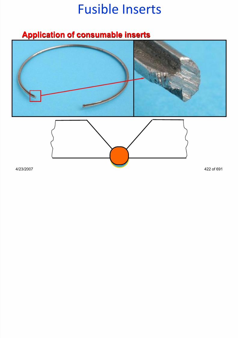
7/22/2019 weldinginspectioncswip-100402035204-phpapp02
http://slidepdf.com/reader/full/weldinginspectioncswip-100402035204-phpapp02 383/636
4/23/2007 422 of 691
Shielding gases for TIG welding
Argon
• low cost and greater availability
• heavier than air - lower flow rates than Helium
• low thermal conductivity - wide top bead profile

7/22/2019 weldinginspectioncswip-100402035204-phpapp02
http://slidepdf.com/reader/full/weldinginspectioncswip-100402035204-phpapp02 384/636
• low ionisation potential - easier arc starting, better arc
stability with AC, cleaning effect
• for the same arc current produce less heat than helium -reduced penetration, wider HAZ
• to obtain the same arc arc power, argon requires a higher
current - increased undercut
4/23/2007 423 of 691
Shielding gases for TIG welding
Helium
• costly and lower availability than Argon
• lighter than air - requires a higher flow rate compared with
argon (2-3 times)

7/22/2019 weldinginspectioncswip-100402035204-phpapp02
http://slidepdf.com/reader/full/weldinginspectioncswip-100402035204-phpapp02 385/636
• higher ionisation potential - poor arc stability with AC, less
forgiving for manual welding
• for the same arc current produce more heat than argon -
increased penetration, welding of metals with high melting
point or thermal conductivity
• to obtain the same arc arc power, helium requires a lower
current - no undercut4/23/2007 424 of 691
Shielding gases for TIG welding
Hydrogen
• not an inert gas - not used as a primary shielding gas
• increase the heat input - faster travel speed and increasedpenetration
• better wetting action - improved bead profile

7/22/2019 weldinginspectioncswip-100402035204-phpapp02
http://slidepdf.com/reader/full/weldinginspectioncswip-100402035204-phpapp02 386/636
better wetting action improved bead profile
•produce a cleaner weld bead surface
• added to argon (up to 5%) - only for austenitic stainlesssteels and nickel alloys
• flammable and explosive
4/23/2007 425 of 691
Shielding gases for TIG welding
Nitrogen
• not an inert gas
• high availability - cheap

7/22/2019 weldinginspectioncswip-100402035204-phpapp02
http://slidepdf.com/reader/full/weldinginspectioncswip-100402035204-phpapp02 387/636
• added to argon (up to 5%) - only for back purge for duplex
stainless, austenitic stainless steels and copper alloys
• not used for mild steels (age embritlement)
• strictly prohibited in case of Ni and Ni alloys (porosity)
4/23/2007 426 of 691
MIG / MAG Consumables(Gases Covered previously)
Welding Consumables

7/22/2019 weldinginspectioncswip-100402035204-phpapp02
http://slidepdf.com/reader/full/weldinginspectioncswip-100402035204-phpapp02 388/636
( p y)
4/23/2007 427 of 691
MIG/MAG Welding ConsumablesWelding consumables for MIG/MAG
• Spools of Continuous electrode wires and shielding gases
• variable spool size (1-15Kg) and Wire diameter (0.6-1.6mm) supplied in random or orderly layers
• Basic Selection of different materials and their alloys as
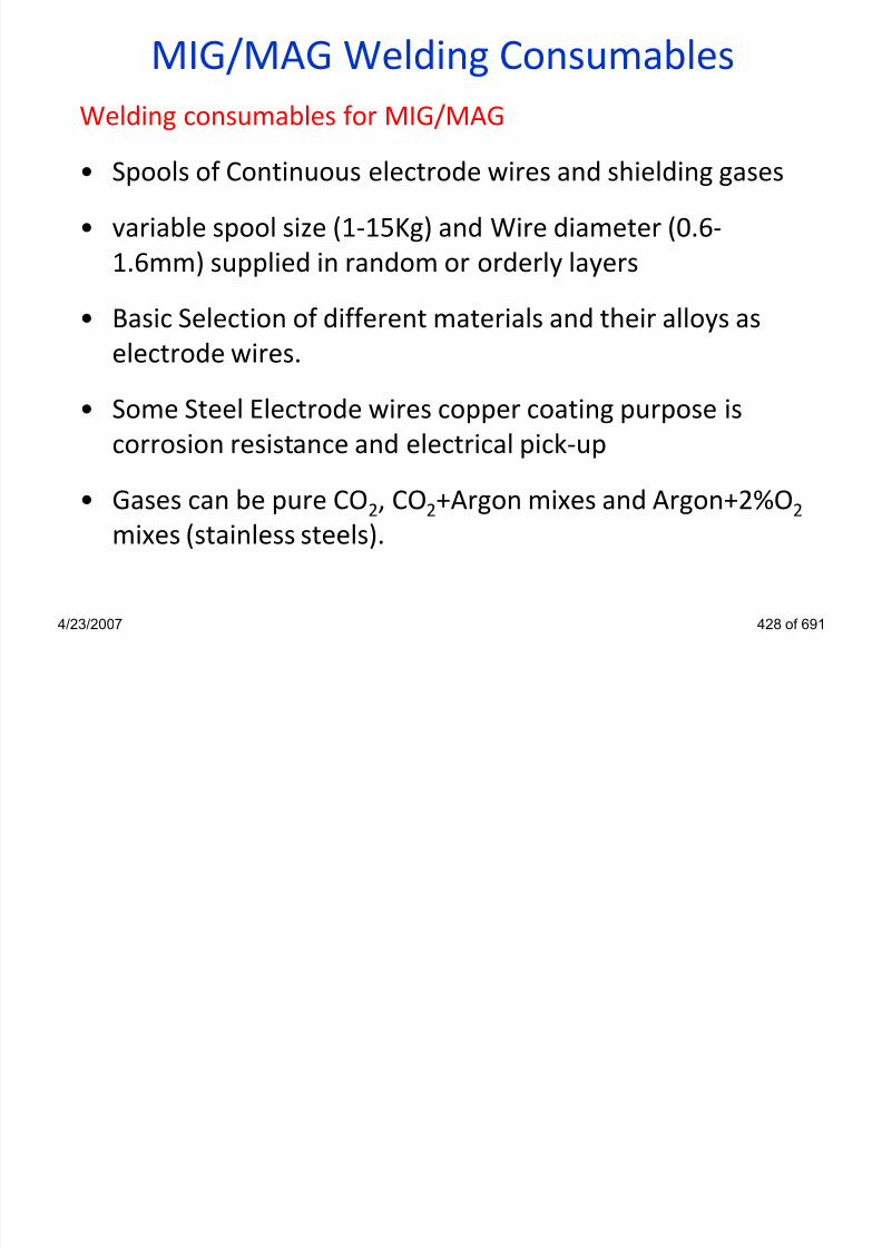
7/22/2019 weldinginspectioncswip-100402035204-phpapp02
http://slidepdf.com/reader/full/weldinginspectioncswip-100402035204-phpapp02 389/636
• Basic Selection of different materials and their alloys as
electrode wires.
• Some Steel Electrode wires copper coating purpose is
corrosion resistance and electrical pick-up
• Gases can be pure CO2, CO2+Argon mixes and Argon+2%O2
mixes (stainless steels).
4/23/2007 428 of 691
MIG/MAG Welding Consumables
Welding wires:
•carbon and low alloy wires may be copper coated
• stainless steel wires are not coated

7/22/2019 weldinginspectioncswip-100402035204-phpapp02
http://slidepdf.com/reader/full/weldinginspectioncswip-100402035204-phpapp02 390/636
4/23/2007 429 of 691
•wires must be kept clean and free from oil and dust
•flux cored wires does not require baking or drying
Courtesy of Lincoln Electric Courtesy of ESAB AB
Flux Core Wire Consumables(Not in training manual)
Welding Consumables

7/22/2019 weldinginspectioncswip-100402035204-phpapp02
http://slidepdf.com/reader/full/weldinginspectioncswip-100402035204-phpapp02 391/636
4/23/2007 433 of 691
Flux Core Wire Consumables

7/22/2019 weldinginspectioncswip-100402035204-phpapp02
http://slidepdf.com/reader/full/weldinginspectioncswip-100402035204-phpapp02 392/636
Functions of metallic sheath: Function of the filling powder:
4/23/2007 434 of 691
provide form stabilityto the wire
serves as currenttransfer duringwelding
stabilise the arcadd alloy elements
produce gaseousshield
produce slag
add iron powder
Types of cored wire
Seamless
cored wire
Butt joint
cored wire
Overlapping
cored wire

7/22/2019 weldinginspectioncswip-100402035204-phpapp02
http://slidepdf.com/reader/full/weldinginspectioncswip-100402035204-phpapp02 393/636
• not sensitive to moisturepick-up
• can be copper coated, bettercurrent transfer
• thick sheath, good formstability, 2 roll drive feeding
possible• difficult to manufacture
• good resistance tomoisture pick-up
• can be copper coated
• thick sheath
• difficult to seal the
sheath
4/23/2007 435 of 691
cored wire cored wire cored wire
sensitive tomoisture pick-
up
cannot be
copper coated
thin sheatheasy to
manufacture
Core elements and their function
Aluminium - deoxidize & denitrify
Calcium - provide shielding & form slag
Carbon - increase hardness & strength
Manganese - deoxidize & increase strength and toughness
Molybdenum - increase hardness & strength
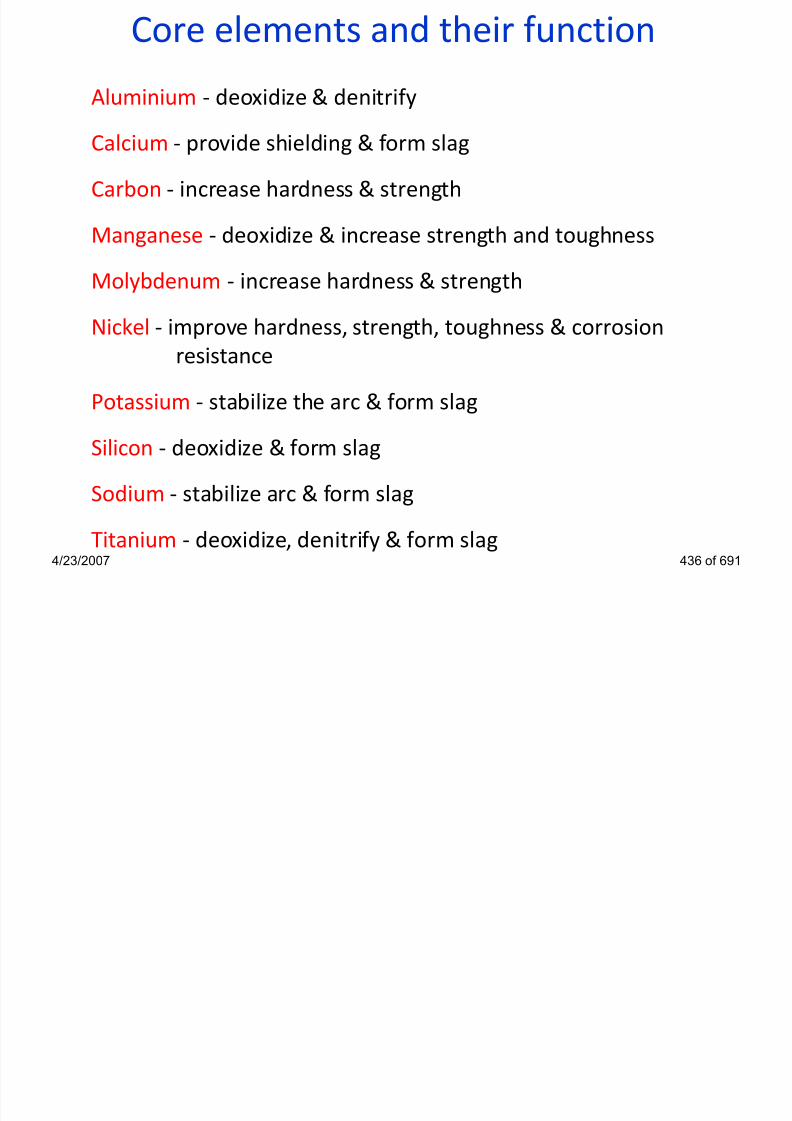
7/22/2019 weldinginspectioncswip-100402035204-phpapp02
http://slidepdf.com/reader/full/weldinginspectioncswip-100402035204-phpapp02 394/636
y g
Nickel - improve hardness, strength, toughness & corrosion
resistance
Potassium - stabilize the arc & form slag
Silicon - deoxidize & form slag
Sodium - stabilize arc & form slag
Titanium - deoxidize, denitrify & form slag4/23/2007 436 of 691
SAW Consumables
Welding Consumables

7/22/2019 weldinginspectioncswip-100402035204-phpapp02
http://slidepdf.com/reader/full/weldinginspectioncswip-100402035204-phpapp02 395/636
4/23/2007 437 of 691
SAW ConsumablesWelding fluxes:
• are granular mineral compounds mixed according to various
formulations
• shield the molten weld pool from the atmosphere
• clean the molten weld pool

7/22/2019 weldinginspectioncswip-100402035204-phpapp02
http://slidepdf.com/reader/full/weldinginspectioncswip-100402035204-phpapp02 396/636
4/23/2007 438 of 691
• can modify the chemical composition of the weld metal
• prevents rapid escape of heat from welding zone
• influence the shape of the weld bead (wetting action)
• can be fused, agglomerated or mixed
• must be kept warm and dry to avoid porosity
SAW Consumables
Welding flux:
• might be fused or agglomerated
• supplied in bags
• must be kept warm and dry
• handling and stacking requires care

7/22/2019 weldinginspectioncswip-100402035204-phpapp02
http://slidepdf.com/reader/full/weldinginspectioncswip-100402035204-phpapp02 397/636
4/23/2007 439 of 691
• Fused fluxes are normally not hygroscopic but particles canhold surface moisture so only drying
• Agglomerated fluxes contain chemically bonded water. Similar
treatment as basic electrodes
• If flux is too fine it will pack and not feed properly. It cannot berecycled indefinitely
handling and stacking requires careCourtesy of Lincoln Electric
SAW Consumables
Fused Flux
• Flaky appearance
• Lower weld quality
• Low moisture intake
• Low dust tendency

7/22/2019 weldinginspectioncswip-100402035204-phpapp02
http://slidepdf.com/reader/full/weldinginspectioncswip-100402035204-phpapp02 398/636
4/23/2007 441 of 691
Fused Flux:
Baked at high temperature, glossy, hard and black in colour,
cannot add ferro-manganese, non moisture absorbent andtends to be of the acidic type
• Good re-cycling
• Very smooth weld
profile
SAW ConsumablesTYPES OF FLUX
FUSED (ACID TYPE)
• name indicates method of manufacture
• minerals are fused (melted) and granules produced byallowing to cool to a solid mass and then crushing or by
spraying the molten flux into water
• flux tends to be „glass-like‟ (high in Silica)

7/22/2019 weldinginspectioncswip-100402035204-phpapp02
http://slidepdf.com/reader/full/weldinginspectioncswip-100402035204-phpapp02 399/636
4/23/2007 442 of 691
g ( g )
• granules are hard and may appear shiny
• granules do not absorb moisture
• granules do not tend break down into powder when being
re-circulated
• are effectively a low hydrogen flux
• welds do not tend to give good toughness at lowtemperatures
SAW ConsumablesFused fluxes advantages:
•good chemical homogeneity
•easy removal of fines without affecting flux
composition
•normally not hygroscopic easy storage and
handling
dil l d ith t i ifi t h i

7/22/2019 weldinginspectioncswip-100402035204-phpapp02
http://slidepdf.com/reader/full/weldinginspectioncswip-100402035204-phpapp02 400/636
4/23/2007 443 of 691
•readily recycled without significant change in
particle size or compositionFused fluxes disadvantages:
•difficult to add deoxidizers and ferro-alloys (due to
segregation or extremely high loss)
•high temperatures needed to melt ingredients limitthe range of flux compositions
SAW ConsumablesAgglomerated Flux
• Granulated appearance
• High weld quality• Addition of alloys
• Lower consumption
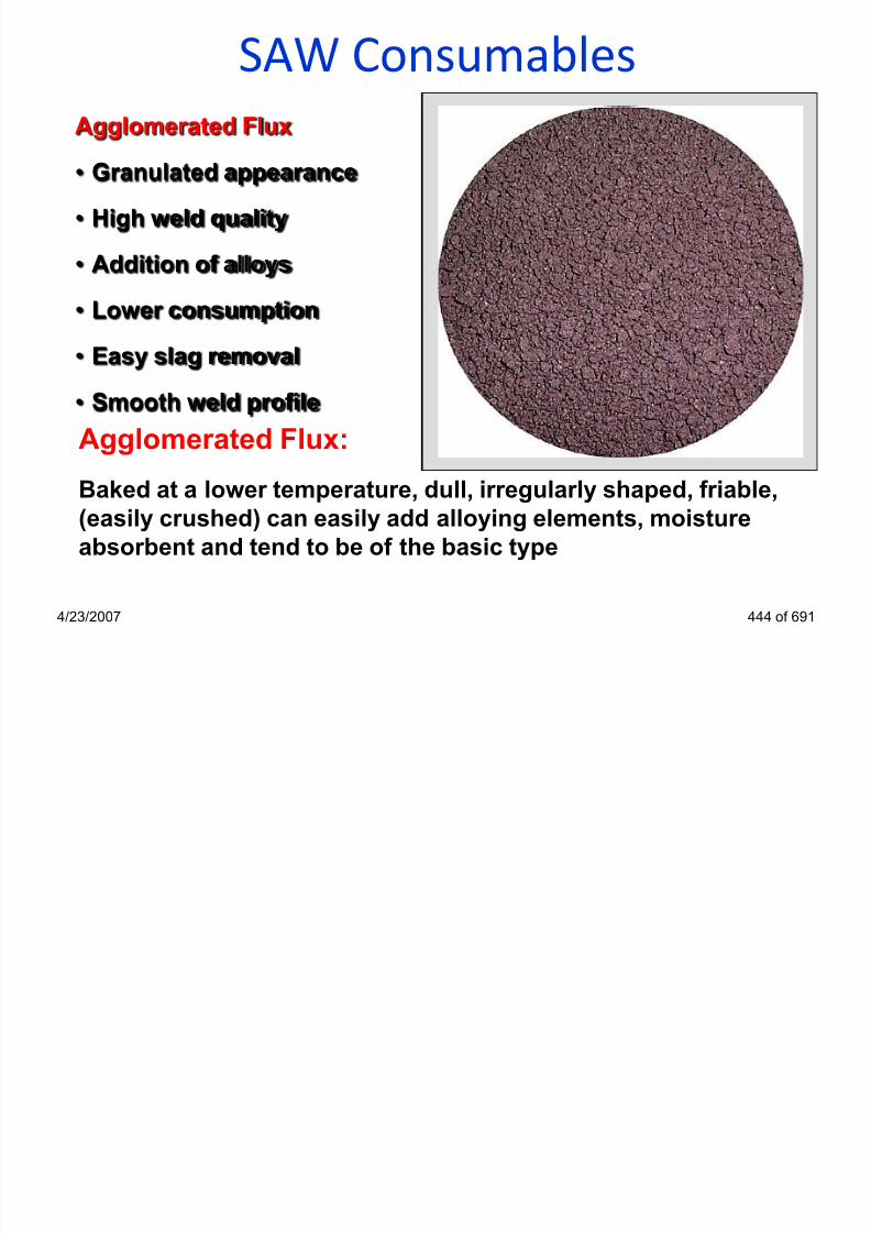
7/22/2019 weldinginspectioncswip-100402035204-phpapp02
http://slidepdf.com/reader/full/weldinginspectioncswip-100402035204-phpapp02 401/636
4/23/2007 444 of 691
Agglomerated Flux:
Baked at a lower temperature, dull, irregularly shaped, friable,
(easily crushed) can easily add alloying elements, moistureabsorbent and tend to be of the basic type
• Easy slag removal
• Smooth weld profile
SAW Consumables
Agglomerated fluxes advantages:
• easy addition of deoxidizers and alloying elements
• usable with thicker layer of flux when welding• colour identification

7/22/2019 weldinginspectioncswip-100402035204-phpapp02
http://slidepdf.com/reader/full/weldinginspectioncswip-100402035204-phpapp02 402/636
4/23/2007 445 of 691
Agglomerated fluxes disadvantages:
• tendency to absorb moisture
• possible gas evolution from the molten slag leading to
porosity
• possible change in flux composition due to segregation orremoval of fine mesh particles
SAW ConsumablesTYPES OF FLUX
AGGLOMERATED (BASIC TYPE)
• name indicates method of manufacture
• basic minerals are used in powder form and are mixed with abinder to form individual granules
• granules are soft and easily crushed to powder

7/22/2019 weldinginspectioncswip-100402035204-phpapp02
http://slidepdf.com/reader/full/weldinginspectioncswip-100402035204-phpapp02 403/636
4/23/2007 446 of 691
• granules will absorb moisture and it is necessary to protect
the flux from moisture pick-up - usually by holding in aheated silo
• granules tend to break down into powder when being re-circulated
• are a low hydrogen flux - if correctly controlled
• welds give good toughness at low temperatures
SAW Consumables
Mixed fluxes advantages:
•several commercial fluxes may be mixed for highly
critical or proprietary welding operations
Mixed fluxes - two or more fused or bonded fluxes are
mixed in any ratio necessary to yield the desired
results
7/22/2019 weldinginspectioncswip-100402035204-phpapp02
http://slidepdf.com/reader/full/weldinginspectioncswip-100402035204-phpapp02 404/636
4/23/2007 447 of 691
Mixed fluxes disadvantages:
•segregation of the combined fluxes duringshipment, storage and handling
•segregation occurring in the feeding and recovery
systems during welding
•inconsistency in the combined flux from mix to mix
SAW filler material
Welding wires can be used to weld:
•carbon steels
•low alloy steels•creep resisting steels
•stainless steels

7/22/2019 weldinginspectioncswip-100402035204-phpapp02
http://slidepdf.com/reader/full/weldinginspectioncswip-100402035204-phpapp02 405/636
4/23/2007 448 of 691
stainless steels
•nickel-base alloys
•special alloys for surfacing applications
Welding wires can be:
•solid wires
•metal-cored wires
SAW filler material
Welding wires:
•carbon and low alloy wires are copper coated
•stainless steel wires are not coated

7/22/2019 weldinginspectioncswip-100402035204-phpapp02
http://slidepdf.com/reader/full/weldinginspectioncswip-100402035204-phpapp02 406/636
4/23/2007 449 of 691
•wires must be kept clean and free from oil and dust
Courtesy of Lincoln Electric Courtesy of Lincoln Electric
SAW filler material
Copper coating functions:
•to assure a good electric contact between wireand contact tip
•to assure a smooth feed of the wire through the
id t b f d ll d t t ti (d

7/22/2019 weldinginspectioncswip-100402035204-phpapp02
http://slidepdf.com/reader/full/weldinginspectioncswip-100402035204-phpapp02 407/636
4/23/2007 450 of 691
guide tube, feed rolls and contact tip (decrease
contact tube wear)
•to provide protection against corrosion
Welding Inspector
Non Destructive Testing
Section 15

7/22/2019 weldinginspectioncswip-100402035204-phpapp02
http://slidepdf.com/reader/full/weldinginspectioncswip-100402035204-phpapp02 408/636
4/23/2007 452 of 691
Non-Destructive Testing
A welding inspector should have a working knowledge of NDT
methods and their applications, advantages and
disadvantages.
Four basic NDT methods
• Radiographic inspection (RT)

7/22/2019 weldinginspectioncswip-100402035204-phpapp02
http://slidepdf.com/reader/full/weldinginspectioncswip-100402035204-phpapp02 409/636
• Radiographic inspection (RT)
• Ultrasonic inspection (UT)
• Magnetic particle inspection (MT)
• Dye penetrant inspection (PT)
4/23/2007 453 of 691
Non-Destructive TestingSurface Crack Detection
• Liquid Penetrant (PT or Dye-Penetrant)
• Magnetic Particle Inspection (MT or MPI)
Volumetric & Planar Inspection
• Ultrasonics (UT)

7/22/2019 weldinginspectioncswip-100402035204-phpapp02
http://slidepdf.com/reader/full/weldinginspectioncswip-100402035204-phpapp02 410/636
4/23/2007 454 of 691
• Radiography (RT)
Each technique has advantages & disadvantages with respect
to:
• Technical Capability and Cost
Note: The choice of NDT techniques is based on considerationof these advantages and disadvantages
Radiographic Testing (RT)

7/22/2019 weldinginspectioncswip-100402035204-phpapp02
http://slidepdf.com/reader/full/weldinginspectioncswip-100402035204-phpapp02 411/636
4/23/2007 455 of 691
g p g ( )
Radiographic Testing
The principles of radiography
• X or Gamma radiation is imposed upon a test object
• Radiation is transmitted to varying degrees
dependant upon the density of the material through
which it is travelling

7/22/2019 weldinginspectioncswip-100402035204-phpapp02
http://slidepdf.com/reader/full/weldinginspectioncswip-100402035204-phpapp02 412/636
4/23/2007 456 of 691
• Thinner areas and materials of a less density show asdarker areas on the radiograph
• Thicker areas and materials of a greater density show
as lighter areas on a radiograph
• Applicable to metals,non-metals and composites
Radiographic Testing

7/22/2019 weldinginspectioncswip-100402035204-phpapp02
http://slidepdf.com/reader/full/weldinginspectioncswip-100402035204-phpapp02 413/636
4/23/2007 457 of 691
X – Rays
Electrically generated
Gamma Rays
Generated by the decay
of unstable atoms
Radiographic TestingSource
Radiation beam Image quality indicator
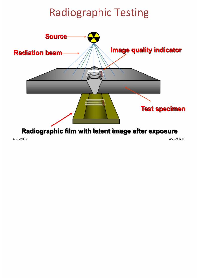
7/22/2019 weldinginspectioncswip-100402035204-phpapp02
http://slidepdf.com/reader/full/weldinginspectioncswip-100402035204-phpapp02 414/636
4/23/2007 458 of 691
Radiographic film with latent image after exposure
Test specimen
Radiographic TestingDensity - relates to the degree of darkness

7/22/2019 weldinginspectioncswip-100402035204-phpapp02
http://slidepdf.com/reader/full/weldinginspectioncswip-100402035204-phpapp02 415/636
4/23/2007 459 of 691
Contrast - relates to the degree of difference
Definition - relates to the degree of sharpness
Sensitivity - relates to the overall quality of the radiograph
Densitometer
Radiographic Sensitivity

7/22/2019 weldinginspectioncswip-100402035204-phpapp02
http://slidepdf.com/reader/full/weldinginspectioncswip-100402035204-phpapp02 416/636
4/23/2007 460 of 691
7FE12
Step / Hole type IQI Wire type IQI
Radiographic Sensitivity

7/22/2019 weldinginspectioncswip-100402035204-phpapp02
http://slidepdf.com/reader/full/weldinginspectioncswip-100402035204-phpapp02 417/636
4/23/2007 461 of 691
Wire Type IQI
Step/Hole Type IQI
Radiographic TechniquesSingle Wall Single Image (SWSI)
• film inside, source outside
Single Wall Single Image (SWSI) panoramic
• film outside, source inside (internal exposure)

7/22/2019 weldinginspectioncswip-100402035204-phpapp02
http://slidepdf.com/reader/full/weldinginspectioncswip-100402035204-phpapp02 418/636
4/23/2007 462 of 691
Double Wall Single Image (DWSI)
• film outside, source outside (external exposure)
Double Wall Double Image (DWDI)
• film outside, source outside (elliptical exposure)
Single Wall Single Image (SWSI)
Film

7/22/2019 weldinginspectioncswip-100402035204-phpapp02
http://slidepdf.com/reader/full/weldinginspectioncswip-100402035204-phpapp02 419/636
4/23/2007 463 of 691
IQI‟s should be placed source side
Film
Single Wall Single Image Panoramic

7/22/2019 weldinginspectioncswip-100402035204-phpapp02
http://slidepdf.com/reader/full/weldinginspectioncswip-100402035204-phpapp02 420/636
4/23/2007 464 of 691
• IQI‟s are placed on the film side
• Source inside film outside (single exposure)
Film
Double Wall Single Image (DWSI)

7/22/2019 weldinginspectioncswip-100402035204-phpapp02
http://slidepdf.com/reader/full/weldinginspectioncswip-100402035204-phpapp02 421/636
4/23/2007 465 of 691
• IQI‟s are placed on the film side
• Source outside film outside (multiple exposure)
• This technique is intended for pipe diametersover 100mm
Film
Double Wall Single Image (DWSI)
• Identification
• Unique identificationEN W10
• IQI placing

7/22/2019 weldinginspectioncswip-100402035204-phpapp02
http://slidepdf.com/reader/full/weldinginspectioncswip-100402035204-phpapp02 422/636
4/23/2007 466 of 691
Radiograph
ID MR11
• IQI placing
A B• Pitch marks indicatingreadable film length
Double Wall Single Image (DWSI)

7/22/2019 weldinginspectioncswip-100402035204-phpapp02
http://slidepdf.com/reader/full/weldinginspectioncswip-100402035204-phpapp02 423/636
4/23/2007 467 of 691
Radiograph
Double Wall Double Image (DWDI)

7/22/2019 weldinginspectioncswip-100402035204-phpapp02
http://slidepdf.com/reader/full/weldinginspectioncswip-100402035204-phpapp02 424/636
4/23/2007 468 of 691
Film
• IQI‟s are placed on the source or film side
• Source outside film outside (multiple exposure)
• A minimum of two exposures
• This technique is intended for pipe diameters less than 100mm
Double Wall Double Image (DWDI)
• Identification
• Unique identification EN W10
• IQI placing
4 3

7/22/2019 weldinginspectioncswip-100402035204-phpapp02
http://slidepdf.com/reader/full/weldinginspectioncswip-100402035204-phpapp02 425/636
4/23/2007 469 of 691
Shot A Radiograph
ID MR12
IQI placing
1 2• Pitch marks indicating
readable film length
Double Wall Double Image (DWDI)
4 3

7/22/2019 weldinginspectioncswip-100402035204-phpapp02
http://slidepdf.com/reader/full/weldinginspectioncswip-100402035204-phpapp02 426/636
4/23/2007 470 of 691
Elliptical Radiograph
1 2
Radiography
PENETRATING POWER
Question:
What determines the penetrating power of an X-ray ?
•the kilo-voltage applied (between anode & cathode)
Question:

7/22/2019 weldinginspectioncswip-100402035204-phpapp02
http://slidepdf.com/reader/full/weldinginspectioncswip-100402035204-phpapp02 427/636
4/23/2007 471 of 691
What determines the penetrating power of a gamma ray ?
•the type of isotope (the wavelength of the gamma rays )
Radiography
GAMMA SOURCES
Isotope Typical Thickness Range
• Iridium 192 10 to 50 mm (mostly used)
• Cobalt 60 > 50 mm
Ytt bi < 10

7/22/2019 weldinginspectioncswip-100402035204-phpapp02
http://slidepdf.com/reader/full/weldinginspectioncswip-100402035204-phpapp02 428/636
4/23/2007 472 of 691
• Ytterbium < 10 mm
• Thulium < 10 mm
• Cesium < 10 mm
Radiographic Testing
Advantages
• Permanent record
• Little surface preparation
• Defect identification
• No material type limitation
N t li t t
Disadvantages
• Expensive consumables
• Bulky equipment
• Harmful radiation
• Defect require significant
depth in relation to the
radiation beam (not good

7/22/2019 weldinginspectioncswip-100402035204-phpapp02
http://slidepdf.com/reader/full/weldinginspectioncswip-100402035204-phpapp02 429/636
4/23/2007 473 of 691
• Not so reliant upon operator
skill
• Thin materials
radiation beam (not good
for planar defects)
• Slow results
• Very little indication of
depths
• Access to both sides
required
Radiograph ic Test ing
Comparison with Ultrasonic Examination
ADVANTAGES
good for non-planar defects
good for thin sections
gives permanent record
i f 2 d t i t t ti

7/22/2019 weldinginspectioncswip-100402035204-phpapp02
http://slidepdf.com/reader/full/weldinginspectioncswip-100402035204-phpapp02 430/636
4/23/2007 474 of 691
easier for 2nd party interpretation
can use on all material types
high productivity
direct image of imperfections
Radiographic Testing
Comparison with Ultrasonic Examination
DISADVANTAGES
• health & safety hazard
• not good for thick sections
• high capital and relatively high running costs

7/22/2019 weldinginspectioncswip-100402035204-phpapp02
http://slidepdf.com/reader/full/weldinginspectioncswip-100402035204-phpapp02 431/636
• not good for planar defects
• X-ray sets not very portable
• requires access to both sides of weld
• frequent replacement of gamma source needed (half life)
4/23/2007 475 of 691
Ultrasonic Testing (UT)

7/22/2019 weldinginspectioncswip-100402035204-phpapp02
http://slidepdf.com/reader/full/weldinginspectioncswip-100402035204-phpapp02 432/636
4/23/2007 476 of 691
Ultrasonic Testing
Main Features:
• Surface and sub-surface detection
• This detection method uses high frequency sound waves,
typically above 2MHz to pass through a material
• A probe is used which contains a piezo electric crystal to
transmit and receive ultrasonic pulses and display the
signals on a cathode ray tube or digital display

7/22/2019 weldinginspectioncswip-100402035204-phpapp02
http://slidepdf.com/reader/full/weldinginspectioncswip-100402035204-phpapp02 433/636
4/23/2007 477 of 691
• The actual display relates to the time taken for theultrasonic pulses to travel the distance to the interface and
back
• An interface could be the back of a plate material or a defect
• For ultrasound to enter a material a couplant must be
introduced between the probe and specimen
Ultrasonic Testing
Digital
UT Set,
Pulse echo
signals
A scan
Display

7/22/2019 weldinginspectioncswip-100402035204-phpapp02
http://slidepdf.com/reader/full/weldinginspectioncswip-100402035204-phpapp02 434/636
4/23/2007 478 of 691
Compression probe checking the material Thickness
Ultrasonic Testing
defect
echo
Back wall
echoinitial pulse

7/22/2019 weldinginspectioncswip-100402035204-phpapp02
http://slidepdf.com/reader/full/weldinginspectioncswip-100402035204-phpapp02 435/636
4/23/2007 479 of 691
defect
0 10 20 30 40 50
CRT DisplayCompression Probe
Material Thk
Ultrasonic Testing
UT SetA Scan
Display

7/22/2019 weldinginspectioncswip-100402035204-phpapp02
http://slidepdf.com/reader/full/weldinginspectioncswip-100402035204-phpapp02 436/636
4/23/2007 480 of 691
Angle Probe
Ultrasonic Testing
initial pulse
defect echo
defect
defect
0 10 20 30 40 50
CRT Display½ Skip

7/22/2019 weldinginspectioncswip-100402035204-phpapp02
http://slidepdf.com/reader/full/weldinginspectioncswip-100402035204-phpapp02 437/636
4/23/2007 481 of 691
defect 0 10 20 30 40 50
initial pulse
defect echo
CRT DisplayFull Skip
Ultrasonic Testing
Advantages
Rapid results
Both surface and
sub-surface detection
Safe
Capable of measuring the
Disadvantages
Trained and skilled operator
required
Requires high operator skill
Good surface finish required
Defect identification

7/22/2019 weldinginspectioncswip-100402035204-phpapp02
http://slidepdf.com/reader/full/weldinginspectioncswip-100402035204-phpapp02 438/636
4/23/2007 482 of 691
Capable of measuring the
depth of defects
May be battery powered
Portable
Couplant may contaminate
No permanent record
Calibration Required
Ferritic Material (Mostly)
Ultrasonic Testing
Comparison with Radiography
ADVANTAGES
•good for planar defects
•good for thick sections
•instant results
•can use on complex joints

7/22/2019 weldinginspectioncswip-100402035204-phpapp02
http://slidepdf.com/reader/full/weldinginspectioncswip-100402035204-phpapp02 439/636
4/23/2007 483 of 691
can use on complex joints
•can automate
•very portable
•no safety problems (‘parallel’ working is possible)
•low capital & running costs
Ultrasonic Testing
Comparison with Radiography
DISADVANTAGES
• no permanent record (with standard equipment)
• not suitable for very thin joints <8mm
• reliant on operator interpretation

7/22/2019 weldinginspectioncswip-100402035204-phpapp02
http://slidepdf.com/reader/full/weldinginspectioncswip-100402035204-phpapp02 440/636
reliant on operator interpretation
• not good for sizing Porosity
• good/smooth surface profile needed
• not suitable for coarse grain materials (e.g., castings)
• Ferritic Materials (with standard equipment)
4/23/2007 484 of 691
Magnetic Particle testing (MT)

7/22/2019 weldinginspectioncswip-100402035204-phpapp02
http://slidepdf.com/reader/full/weldinginspectioncswip-100402035204-phpapp02 441/636
4/23/2007 485 of 691
Magnetic Particle Testing
Main features:
• Surface and slight sub-surface detection
• Relies on magnetization of component being tested
• Only Ferro-magnetic materials can be tested
• A magnetic field is introduced into a specimen being tested
• Methods of applying a magnetic field, yoke, permanentmagnet, prods and flexible cables.

7/22/2019 weldinginspectioncswip-100402035204-phpapp02
http://slidepdf.com/reader/full/weldinginspectioncswip-100402035204-phpapp02 442/636
magnet, prods and flexible cables.
• Fine particles of iron powder are applied to the test area
• Any defect which interrupts the magnetic field, will create aleakage field, which attracts the particles
• Any defect will show up as either a dark indication or in thecase of fluorescent particles under UV-A light a green/yellowindication
4/23/2007 486 of 691
Magnetic Particle Testing
Electro-magnet (yoke) DC or AC
Collection of ink
particles due to
leakage field
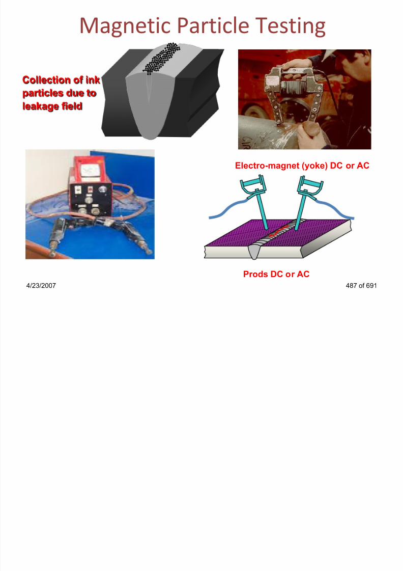
7/22/2019 weldinginspectioncswip-100402035204-phpapp02
http://slidepdf.com/reader/full/weldinginspectioncswip-100402035204-phpapp02 443/636
4/23/2007 487 of 691
Electro-magnet (yoke) DC or AC
Prods DC or AC
Magnetic Particle Testing
A crack like
indication

7/22/2019 weldinginspectioncswip-100402035204-phpapp02
http://slidepdf.com/reader/full/weldinginspectioncswip-100402035204-phpapp02 444/636
4/23/2007 488 of 691
Magnetic Particle Testing

7/22/2019 weldinginspectioncswip-100402035204-phpapp02
http://slidepdf.com/reader/full/weldinginspectioncswip-100402035204-phpapp02 445/636
4/23/2007 489 of 691
Alternatively to contrast inks, fluorescent inks may be used
for greater sensitivity. These inks require a UV-A light source
and a darkened viewing area to inspect the component
Magnetic Particle Testing
Typical sequence of operations to inspect a weld
• Clean area to be tested
• Apply contrast paint• Apply magnetisism to the component
• Apply ferro-magnetic ink to the component during
magnatising

7/22/2019 weldinginspectioncswip-100402035204-phpapp02
http://slidepdf.com/reader/full/weldinginspectioncswip-100402035204-phpapp02 446/636
4/23/2007 490 of 691
• Iterpret the test area
• Post clean and de-magnatise if required
Magnetic Particle Testing
Advantages
• Simple to use
• Inexpensive
• Rapid results
• Little surface preparation
required
Disadvantages
• Surface or slight sub-surface
detection only
• Magnetic materials only
• No indication of defects
depths
Only suitable for linear

7/22/2019 weldinginspectioncswip-100402035204-phpapp02
http://slidepdf.com/reader/full/weldinginspectioncswip-100402035204-phpapp02 447/636
4/23/2007 491 of 691
• Possible to inspect throughthin coatings
• Only suitable for linear
defects
• Detection is required in two
directions
Magnetic Particle Testing
Comparison with Penetrant Testing
ADVANTAGES
• much quicker than PT
• instant results
• can detect near-surface imperfections (by current f low
technique)
• less surface preparation needed

7/22/2019 weldinginspectioncswip-100402035204-phpapp02
http://slidepdf.com/reader/full/weldinginspectioncswip-100402035204-phpapp02 448/636
4/23/2007 492 of 691
• less surface preparation needed
DISADVANTAGES
• only suitable for ferromagnetic materials
• electrical power for most techniques
• may need to de-magnetise (machine components)
Penetrant Testing (PT)

7/22/2019 weldinginspectioncswip-100402035204-phpapp02
http://slidepdf.com/reader/full/weldinginspectioncswip-100402035204-phpapp02 449/636
4/23/2007 493 of 691
Penetrant TestingMain features:
• Detection of surface breaking defects only.
• This test method uses the forces of capillary action
• Applicable on any material type, as long they are non porous.
• Penetrants are available in many different types:
• Water washable contrast

7/22/2019 weldinginspectioncswip-100402035204-phpapp02
http://slidepdf.com/reader/full/weldinginspectioncswip-100402035204-phpapp02 450/636
• Water washable contrast
• Solvent removable contrast
• Water washable fluorescent
• Solvent removable fluorescent
• Post-emulsifiable fluorescent
4/23/2007 494 of 691
Penetrant TestingStep 1. Pre-Cleaning
Ensure surface is very Clean normally with the use of a solvent

7/22/2019 weldinginspectioncswip-100402035204-phpapp02
http://slidepdf.com/reader/full/weldinginspectioncswip-100402035204-phpapp02 451/636
4/23/2007 495 of 691
Penetrant Testing
Step 2. Apply penetrant
After the application, the penetrant is normally left on the
components surface for approximately 15-20 minutes (dwell
time).
The penetrant enters any defects that may be present bycapillary action.

7/22/2019 weldinginspectioncswip-100402035204-phpapp02
http://slidepdf.com/reader/full/weldinginspectioncswip-100402035204-phpapp02 452/636
4/23/2007 496 of 691
Penetrant Testing
Step 3. Clean off penetrant
the penetrant is removed after sufficient penetration time (dwell
time).
Care must be taken not to wash any penetrant out off any
defects present

7/22/2019 weldinginspectioncswip-100402035204-phpapp02
http://slidepdf.com/reader/full/weldinginspectioncswip-100402035204-phpapp02 453/636
4/23/2007 497 of 691
Penetrant Testing
Step 3. Apply developer
After the penetrant has be cleaned sufficiently, a thin layer of
developer is applied.
The developer acts as a contrast against the penetrant and
allows for reverse capillary action to take place.

7/22/2019 weldinginspectioncswip-100402035204-phpapp02
http://slidepdf.com/reader/full/weldinginspectioncswip-100402035204-phpapp02 454/636
4/23/2007 498 of 691
Penetrant Testing
Step 4. Inspection / development time
Inspection should take place immediately after the developer
has been applied.
any defects present will show as a bleed out during
development time.After full inspection has been carried out post cleaning is
generally required.

7/22/2019 weldinginspectioncswip-100402035204-phpapp02
http://slidepdf.com/reader/full/weldinginspectioncswip-100402035204-phpapp02 455/636
4/23/2007 499 of 691
Penetrant Testing
Fluorescent Penetrant Bleed out viewedunder a UV-A lightsource

7/22/2019 weldinginspectioncswip-100402035204-phpapp02
http://slidepdf.com/reader/full/weldinginspectioncswip-100402035204-phpapp02 456/636
4/23/2007 500 of 691
Colour contrast Penetrant
Bleed out viewed
under white light
Penetrant Testing
Advantages
• Simple to use
• Inexpensive
• Quick results
• Can be used on any non-
porous material
Disadvantages
• Surface breaking defect only
• little indication of depths• Penetrant may contaminate
component
• Surface preparation critical
• Post cleaning required

7/22/2019 weldinginspectioncswip-100402035204-phpapp02
http://slidepdf.com/reader/full/weldinginspectioncswip-100402035204-phpapp02 457/636
• Portability
• Low operator skill required
• Post cleaning required
• Potentially hazardouschemicals
• Can not test unlimited times
• Temperature dependant
4/23/2007 501 of 691
Penetrant Testing
Comparison with Magnetic Particle Inspection
ADVANTAGES
•easy to interpret results
•no power requirements
•relatively little training required
•can use on all materials

7/22/2019 weldinginspectioncswip-100402035204-phpapp02
http://slidepdf.com/reader/full/weldinginspectioncswip-100402035204-phpapp02 458/636
4/23/2007 502 of 691
DISADVANTAGES
•good surface finish needed
•relatively slow
•chemicals - health & safety issue
Welding Inspector
Weld Repairs
Section 16

7/22/2019 weldinginspectioncswip-100402035204-phpapp02
http://slidepdf.com/reader/full/weldinginspectioncswip-100402035204-phpapp02 459/636
4/23/2007 503 of 691
Weld RepairsWeld repairs can be divided into 2 specific areas:
• Production repairs
• In service repairs

7/22/2019 weldinginspectioncswip-100402035204-phpapp02
http://slidepdf.com/reader/full/weldinginspectioncswip-100402035204-phpapp02 460/636
4/23/2007 504 of 691
Weld Repairs
A weld repair can be a relatively straight forward activity, but
in many instances it is quite complex, and various
engineering disciplines may need to be involved to ensure a
successful outcome.
• Analysis of the defect types may be carried out by the
Q/C department to discover the likely reason for their
occurrence, (Material/Process or Skill related).

7/22/2019 weldinginspectioncswip-100402035204-phpapp02
http://slidepdf.com/reader/full/weldinginspectioncswip-100402035204-phpapp02 461/636
In general terms, a welding repair involves What!
4/23/2007 505 of 691
Weld Repairs
A weld repair may be used to improve weld profiles or
extensive metal removal:
•Repairs to fabrication defects are generally easier than
repairs to service failures because the repair procedure
may be followed
•The main problem with repairing a weld is the

7/22/2019 weldinginspectioncswip-100402035204-phpapp02
http://slidepdf.com/reader/full/weldinginspectioncswip-100402035204-phpapp02 462/636
maintenance of mechanical properties•During the inspection of the removed area prior to
welding the inspector must ensure that the defects have
been totally removed and the original joint profile has
been maintained as close as possible
4/23/2007 506 of 691
Weld RepairsIn the event of repair, it is required:
• Authorization and procedure for repair
• Removal of material and preparation for repair
• Monitoring of repair Weld

7/22/2019 weldinginspectioncswip-100402035204-phpapp02
http://slidepdf.com/reader/full/weldinginspectioncswip-100402035204-phpapp02 463/636
• Testing of repair - visual and NDT
4/23/2007 507 of 691
Weld Repairs
There are a number of key factors that need to be considered
before undertaking any repair:
• The most important - is it financially worthwhile?
• Can structural integrity be achieved if the item is repaired?
• Are there any alternatives to welding?
• What caused the defect and is it likely to happen again?

7/22/2019 weldinginspectioncswip-100402035204-phpapp02
http://slidepdf.com/reader/full/weldinginspectioncswip-100402035204-phpapp02 464/636
y pp g
• How is the defect to be removed and what welding process is to
be used?
• What NDE is required to ensure complete removal of the defect?
• Will the welding procedures require approval/re-approval?
4/23/2007 508 of 691
Weld Repairs• Cleaning the repair area, (removal of paint, grease, etc)
• A detailed assessment to find out the extremity of the defect.This may involve the use of a surface or sub surface NDE method.
• Once established the excavation site must be clearly identifiedand marked out.
• An excavation procedure may be required (method used i.e.grinding, arc-air gouging, preheat requirements etc).

7/22/2019 weldinginspectioncswip-100402035204-phpapp02
http://slidepdf.com/reader/full/weldinginspectioncswip-100402035204-phpapp02 465/636
• NDE should be used to locate the defect and confirm its removal.
• A welding repair procedure/method statement with theappropriate welding process, consumable, technique, controlledheat input and interpass temperatures etc will need to beapproved.
4/23/2007 509 of 691
Weld Repairs
• Use of approved welders.
• Dressing the weld and final visual.
• A NDT procedure/technique prepared and carried out to ensurethat the defect has been successfully removed and repaired.
• Any post repair heat treatment requirements.
• Final NDT procedure/technique prepared and carried out after

7/22/2019 weldinginspectioncswip-100402035204-phpapp02
http://slidepdf.com/reader/full/weldinginspectioncswip-100402035204-phpapp02 466/636
heat treatment requirements.
• Applying protective treatments (painting etc as required).
• (*Appropriate’ means suitable for the alloys being repaired and
may not apply in specific situations)
4/23/2007 510 of 691
Weld Repairs
• What will be the effect of welding distortion and residual
stress?
• Will heat treatment be required?
• What NDE is required and how can acceptability of the
repair be demonstrated?
• Will approval of the repair be required – if yes, how and by

7/22/2019 weldinginspectioncswip-100402035204-phpapp02
http://slidepdf.com/reader/full/weldinginspectioncswip-100402035204-phpapp02 467/636
whom?
4/23/2007 511 of 691
Production Weld Repairs
Before the repair can commence, a number of elements need
to be fulfilled:
If the defect is surface breaking and has occurred at the fusion
face the problem could be cracking or lack of sidewall fusion.If the defect is found to be cracking the cause may be
associated with the material or the welding procedure
If the defect is lack of sidewall fusion this can be apportioned
to the lack of skill of the welder.

7/22/2019 weldinginspectioncswip-100402035204-phpapp02
http://slidepdf.com/reader/full/weldinginspectioncswip-100402035204-phpapp02 468/636
4/23/2007 512 of 691
In this particular case as the defect is open to the surface, MPI
or DYE-PEN may be used to gauge the length of the defect and
U/T inspection used to gauge the depth.
Weld Repairs
The specification or procedure will govern how the defective
areas are to be removed. The method of removal may be:
•Grinding
•Chipping
•Machining

7/22/2019 weldinginspectioncswip-100402035204-phpapp02
http://slidepdf.com/reader/full/weldinginspectioncswip-100402035204-phpapp02 469/636
•Filing
•Oxy-Gas gouging
•Arc air gouging
4/23/2007 513 of 691
Defect Excavation
Arc -ai r goug ing

7/22/2019 weldinginspectioncswip-100402035204-phpapp02
http://slidepdf.com/reader/full/weldinginspectioncswip-100402035204-phpapp02 470/636
4/23/2007 514 of 691
Arc-air gouging features
• Operate ONLY on DCEP
• Special gouging copper
coated carbon electrode
• Can be used on carbonand low alloy steels,
austenitic stainless steels
and non-ferrous materials
• Requires CLEAN/DRY

7/22/2019 weldinginspectioncswip-100402035204-phpapp02
http://slidepdf.com/reader/full/weldinginspectioncswip-100402035204-phpapp02 471/636
4/23/2007 515 of 691
Requires CLEAN/DRY
compressed air supply
• Provides fast rate of metal removal
• Can remove complex shape defects
• After gouging, grinding of carbured layer is mandatory
• Gouging doesn‟t require a qualified welder!
Production Weld Repairs
Production Repairs
• are usually identified during production inspection
• evaluation of the reports is usually carried out bythe Welding Inspector, or NDT operator

7/22/2019 weldinginspectioncswip-100402035204-phpapp02
http://slidepdf.com/reader/full/weldinginspectioncswip-100402035204-phpapp02 472/636
4/23/2007 516 of 691
Production Weld Repairs
Plan View of defect

7/22/2019 weldinginspectioncswip-100402035204-phpapp02
http://slidepdf.com/reader/full/weldinginspectioncswip-100402035204-phpapp02 473/636
4/23/2007 517 of 691
Production Weld RepairsSide View of defect excavation
D
W
Side View of repair welding

7/22/2019 weldinginspectioncswip-100402035204-phpapp02
http://slidepdf.com/reader/full/weldinginspectioncswip-100402035204-phpapp02 474/636
4/23/2007 518 of 691
In Service Weld Repairs
In service repairs
• Can be of a very complex nature, as the component is very
likely to be in a different welding position and condition
than it was during production
• It may also have been in contact with toxic, or combustible
fluids hence a permit to work will need to be sought prior
to any work being carried out

7/22/2019 weldinginspectioncswip-100402035204-phpapp02
http://slidepdf.com/reader/full/weldinginspectioncswip-100402035204-phpapp02 475/636
y g
• The repair welding procedure may look very different to the
original production procedure due to changes in these
elements.
4/23/2007 519 of 691
In Service Weld Repairs
Other factors to be taken into consideration:
Effect of heat on any surrounding areas of the component
i.e. electrical components, or materials that may become
damaged by the repair procedure.
This may also include difficulty in carrying out any required
pre or post welding heat treatments and a possible
restriction of access to the area to be repaired.

7/22/2019 weldinginspectioncswip-100402035204-phpapp02
http://slidepdf.com/reader/full/weldinginspectioncswip-100402035204-phpapp02 476/636
p
For large fabrications it is likely that the repair must also
take place on site and without a shut down of operations,
which may bring other elements that need to be
considered.
4/23/2007 520 of 691
Weld Repairs
• Is welding the best method of repair?
• Is the repair really like earlier repairs?
• What is the composition and weldability of the base metal?
• What strength is required from the repair?
• Can preheat be tolerated?
• Can softening or hardening of the HAZ be tolerated?

7/22/2019 weldinginspectioncswip-100402035204-phpapp02
http://slidepdf.com/reader/full/weldinginspectioncswip-100402035204-phpapp02 477/636
g g
• Is PWHT necessary and practicable?
• Will the fatigue resistance of the repair be adequate?
•Will the repair resist its environment?
• Can the repair be inspected and tested?
4/23/2007 521 of 691
Weld repair related problems
• heat from welding may affect dimensional stability and/or
mechanical properties of repaired assembly
• due to heat from welding, YS goes down, danger of
collapse
• filler materials used on dissimilar welds may lead to
galvanic corrosion

7/22/2019 weldinginspectioncswip-100402035204-phpapp02
http://slidepdf.com/reader/full/weldinginspectioncswip-100402035204-phpapp02 478/636
• local preheat may induce residual stresses
• cost of weld metal deposited during a weld joint repair
can reach up to 10 times the original weld metal cost!
4/23/2007 522 of 691
Welding Inspector
Residual Stress & Distortion
Section 17

7/22/2019 weldinginspectioncswip-100402035204-phpapp02
http://slidepdf.com/reader/full/weldinginspectioncswip-100402035204-phpapp02 479/636
4/23/2007 523 of 691
Residual stressResidual stresses are undesirable because:
they lead to distortionthey affect dimensional stability of the
welded assembly
7/22/2019 weldinginspectioncswip-100402035204-phpapp02
http://slidepdf.com/reader/full/weldinginspectioncswip-100402035204-phpapp02 480/636
4/23/2007 524 of 691
they enhance the risk of brittle fracture
they can facilitate certain types of
corrosion
Residual StressesThe heating and subsequent cooling from welding producesexpansion and contractions which affect the weld metal andadjacent material.
If this contraction is prevented or inhibited residual stress will
develop.
The tendency to develop residual stresses increases when theheating and cooling is localised.
Residual stresses are very difficult to measure with any real

7/22/2019 weldinginspectioncswip-100402035204-phpapp02
http://slidepdf.com/reader/full/weldinginspectioncswip-100402035204-phpapp02 481/636
4/23/2007 525 of 691
accuracy.Residual stresses are self balancing internal forces and notstresses induced whilst applying external load
Stresses are more concentrated at the surface of thecomponent.
The removal of residual stresses is termed stress relieving.
Stresses
Normal Stress
Stress arising from a force perpendicular to the
cross sectional area
Compression

7/22/2019 weldinginspectioncswip-100402035204-phpapp02
http://slidepdf.com/reader/full/weldinginspectioncswip-100402035204-phpapp02 482/636
4/23/2007 526 of 691
Tension
Stresses
Shear Stress
Stress arising from forces which are parallel to, and
lie in the plane of the cross sectional area.

7/22/2019 weldinginspectioncswip-100402035204-phpapp02
http://slidepdf.com/reader/full/weldinginspectioncswip-100402035204-phpapp02 483/636
4/23/2007 527 of 691
Shear Stress
Stresses
Hoop Stress
Internal stress acting on the wall a pipe or cylinder
due to internal pressure.

7/22/2019 weldinginspectioncswip-100402035204-phpapp02
http://slidepdf.com/reader/full/weldinginspectioncswip-100402035204-phpapp02 484/636
4/23/2007 528 of 691
Hoop Stress
Residual Stresses
Longitudinal
Along the weld – longitudinal residual stresses
Across the weld – transverse residual stresses
Through the weld – short transverse residual stresses
Residual stresses occur in welds in the following directions

7/22/2019 weldinginspectioncswip-100402035204-phpapp02
http://slidepdf.com/reader/full/weldinginspectioncswip-100402035204-phpapp02 485/636
4/23/2007 529 of 691
Transverse
Short Transverse
Residual stress
Heating and
cooling causesexpansion and
contraction

7/22/2019 weldinginspectioncswip-100402035204-phpapp02
http://slidepdf.com/reader/full/weldinginspectioncswip-100402035204-phpapp02 486/636
4/23/2007 530 of 691
Residual stress
In case of a heated
bar, the resistanceof the surrounding
material to the
i d

7/22/2019 weldinginspectioncswip-100402035204-phpapp02
http://slidepdf.com/reader/full/weldinginspectioncswip-100402035204-phpapp02 487/636
4/23/2007 531 of 691
expansion andcontraction leads
to formation of
residual stress
Summary
1. Residual stresses are locked in elastic strain, which is
caused by local expansion and contraction in the weld
area.
2. Residual stresses should be removed from structures
after welding.
3. The amount of contraction is controlled by, the volume of
weld metal in the joint, the thickness, heat input, joint
design and the materials properties

7/22/2019 weldinginspectioncswip-100402035204-phpapp02
http://slidepdf.com/reader/full/weldinginspectioncswip-100402035204-phpapp02 488/636
4/23/2007 532 of 691
4. Offsetting may be used to finalise the position of the joint.
5. If plates or pipes are prevented from moving by tacking,
clamping or jigging etc (restraint), then the amount of
residual stresses that remain will be higher.
Summary
6. The movement caused by welding related stresses is
called distortion.
7. The directions of contractional stresses and distortion is
very complex, as is the amount and type of final distortion,
however we can say that there are three directions:
a. Longi tud ina l b. Transverse c. Short transv erse
8. A high percentage of residual stresses can be removed by
heat treatments.

7/22/2019 weldinginspectioncswip-100402035204-phpapp02
http://slidepdf.com/reader/full/weldinginspectioncswip-100402035204-phpapp02 489/636
4/23/2007 533 of 691
9. The peening of weld faces will only redistribute the
residual stress, and place the weld face in compression.
Types of distortion
Angular distortion

7/22/2019 weldinginspectioncswip-100402035204-phpapp02
http://slidepdf.com/reader/full/weldinginspectioncswip-100402035204-phpapp02 490/636
4/23/2007 534 of 691
Distortion
Angular DistortionTransverse Distortion

7/22/2019 weldinginspectioncswip-100402035204-phpapp02
http://slidepdf.com/reader/full/weldinginspectioncswip-100402035204-phpapp02 491/636
4/23/2007 535 of 691
Bowing Distortion Longitudinal Distortion
Distortion
Factors which affect distortion
• Material properties and condition
• Heat input
• The amount of restrain
• The amount of weld metal deposited
Control of distortion my be achieved in the following way:
Th d f diff t j i t d i

7/22/2019 weldinginspectioncswip-100402035204-phpapp02
http://slidepdf.com/reader/full/weldinginspectioncswip-100402035204-phpapp02 492/636
4/23/2007 536 of 691
•The used of a different joint design
•Presetting the joints to be welded – so that the metal distorts
into the required position.
•The use of a balanced welding technique
•The use of clamps, jigs and fixtures.
Distortion
• Distortion will occur in all welded joints if the material are
free to move i.e. not restrained
• Restrained materials result in low distortion but high
residual stress
• More than one type of distortion may occur at one time
• Highly restrained joints also have a higher crack tendency
than joints of a low restraint
The action of resid al stress in elded joints is to ca se

7/22/2019 weldinginspectioncswip-100402035204-phpapp02
http://slidepdf.com/reader/full/weldinginspectioncswip-100402035204-phpapp02 493/636
4/23/2007 537 of 691
• The action of residual stress in welded joints is to causedistortion
DistortionFactors affecting distortion:
parent material properties
amount of restrain
joint design

7/22/2019 weldinginspectioncswip-100402035204-phpapp02
http://slidepdf.com/reader/full/weldinginspectioncswip-100402035204-phpapp02 494/636
4/23/2007 538 of 691
fit-up
welding sequence
Factors affecting distortion
Parent material properties:
thermal expansion coefficient - the greater the value, thegreater the residual stress
yield strength - the greater the value, the greater theresidual stress
Young‟s modulus - the greater the value (increase instiffness), the greater the residual stress
thermal conductivity - the higher the value, the lower theid l t
7/22/2019 weldinginspectioncswip-100402035204-phpapp02
http://slidepdf.com/reader/full/weldinginspectioncswip-100402035204-phpapp02 495/636
4/23/2007 539 of 691
residual stress
transformation temperature - during phasetransformation, expansion/contraction takes place. Thelower the transformation temperature, the lower the
residual stress
Factors affecting distortion
Joint design:
weld metal volume
type of joint - butt vs. fillet, single vs. double side
Amount of restrain:
thickness - as thickness increase, so do the stresses
high level of restrain lead to high stresses
preheat may increase the level of stresses (pipe

7/22/2019 weldinginspectioncswip-100402035204-phpapp02
http://slidepdf.com/reader/full/weldinginspectioncswip-100402035204-phpapp02 496/636
4/23/2007 540 of 691
preheat may increase the level of stresses (pipewelding!)
Fit-up:misalignment may reduce stresses in some cases
root gap - increase in root gap increases shrinkage
Factors affecting distortion
Welding sequence:
number of passes - every pass adds to the total
contraction
heat input - the higher the heat input, the greater
the shrinkage
travel speed - the faster the welding speed, the
less the stress

7/22/2019 weldinginspectioncswip-100402035204-phpapp02
http://slidepdf.com/reader/full/weldinginspectioncswip-100402035204-phpapp02 497/636
4/23/2007 541 of 691
less the stressbuild-up sequence
Distortion prevention
Distortion prevention by pre-setting
a) pre-setting of fillet joint to
prevent angular distortion
b) pre-setting of butt joint to
prevent angular distortion

7/22/2019 weldinginspectioncswip-100402035204-phpapp02
http://slidepdf.com/reader/full/weldinginspectioncswip-100402035204-phpapp02 498/636
4/23/2007 542 of 691
prevent angular distortionc) tapered gap to prevent
closure
Distortion
Pre-set or Offsetting:
The amount of offsetting required is generally a function of
trial and error.

7/22/2019 weldinginspectioncswip-100402035204-phpapp02
http://slidepdf.com/reader/full/weldinginspectioncswip-100402035204-phpapp02 499/636
4/23/2007 543 of 691
Distortion prevention
Distortion prevention by pre-bending usingstrongbacks and wedges

7/22/2019 weldinginspectioncswip-100402035204-phpapp02
http://slidepdf.com/reader/full/weldinginspectioncswip-100402035204-phpapp02 500/636
4/23/2007 544 of 691
DistortionClamping and jigging:
The materials to be welded are prevented from moving by theclamp or jig the main advantage of using a jig is that theelements in a fabrication can be precisely located in theposition to be welded. Main disadvantage of jigging is high
restraint and high levels of residual stresses.

7/22/2019 weldinginspectioncswip-100402035204-phpapp02
http://slidepdf.com/reader/full/weldinginspectioncswip-100402035204-phpapp02 501/636
4/23/2007 545 of 691
Distortion preventionDistortion prevention by restraint techniques
a) use of welding jigs

7/22/2019 weldinginspectioncswip-100402035204-phpapp02
http://slidepdf.com/reader/full/weldinginspectioncswip-100402035204-phpapp02 502/636
4/23/2007 546 of 691
b) use of flexible
clamps
Distortion preventionDistortion prevention by restraint techniques
c) use of strongbacks
with wedges

7/22/2019 weldinginspectioncswip-100402035204-phpapp02
http://slidepdf.com/reader/full/weldinginspectioncswip-100402035204-phpapp02 503/636
4/23/2007 547 of 691
d) use of fully welded
strongbacks
Distortion prevention
Distortion prevention by design
Consider eliminating the welding!!

7/22/2019 weldinginspectioncswip-100402035204-phpapp02
http://slidepdf.com/reader/full/weldinginspectioncswip-100402035204-phpapp02 504/636
4/23/2007 548 of 691
a) by forming the plate
b) by use of rolled or extruded sections
Distortion prevention
Distortion prevention by design
consider weld placement

7/22/2019 weldinginspectioncswip-100402035204-phpapp02
http://slidepdf.com/reader/full/weldinginspectioncswip-100402035204-phpapp02 505/636
4/23/2007 549 of 691
reduce weld metal volume
and/or number of runs
Distortion preventionThe volume of weld metal in a joint will affect the amount oflocal expansion and contraction, hence the more welddeposited the higher amount of distortion
Preparation angle 60o
Preparation angle 40o

7/22/2019 weldinginspectioncswip-100402035204-phpapp02
http://slidepdf.com/reader/full/weldinginspectioncswip-100402035204-phpapp02 506/636
4/23/2007 550 of 691
Preparation angle 0o
Distortion prevention
Distortion prevention by design
use of balanced welding

7/22/2019 weldinginspectioncswip-100402035204-phpapp02
http://slidepdf.com/reader/full/weldinginspectioncswip-100402035204-phpapp02 507/636
4/23/2007 551 of 691
Distortion prevention
- Transverse Shrinkage
Fillet Welds 0.8mm per weld where the leg length
does not exceed 3/4 plate thickness
Butt weld 1 5 to 3mm per weld for 60° V joint
Allowances to cover shrinkage
Distortions prevention by design

7/22/2019 weldinginspectioncswip-100402035204-phpapp02
http://slidepdf.com/reader/full/weldinginspectioncswip-100402035204-phpapp02 508/636
4/23/2007 552 of 691
Butt weld 1.5 to 3mm per weld for 60 V joint,depending on number of runs
- Longitudinal Shrinkage
Fillet Welds 0.8mm per 3m of weld
Butt Welds 3mm per 3m of weld
Distortion prevention
Distortion prevention by fabrication techniques
tack weldinga) tack weld straight through
to end of joint
b) tack weld one end, then use
back-step technique for
tacking the rest of the joint

7/22/2019 weldinginspectioncswip-100402035204-phpapp02
http://slidepdf.com/reader/full/weldinginspectioncswip-100402035204-phpapp02 509/636
4/23/2007 553 of 691
tacking the rest of the jointc) tack weld the centre, then
complete the tack welding
by the back-step technique
Distortion prevention
Distortion prevention by fabrication techniques
back to back assembly
a) assemblies tacked together
before welding
b) use of wedges for

7/22/2019 weldinginspectioncswip-100402035204-phpapp02
http://slidepdf.com/reader/full/weldinginspectioncswip-100402035204-phpapp02 510/636
4/23/2007 554 of 691
b) use of wedges forcomponents that distort on
separation after welding
Distortion prevention
Distortion prevention by fabrication techniques
use of stiffeners

7/22/2019 weldinginspectioncswip-100402035204-phpapp02
http://slidepdf.com/reader/full/weldinginspectioncswip-100402035204-phpapp02 511/636
4/23/2007 555 of 691
control welding process by:
- deposit the weld metal as quickly as possible
- use the least number of runs to fill the joint
Distortion prevention
Distortion prevention by welding procedure
reduce the number of
runs required to make a
weld (e.g. angular
distortion as a function

7/22/2019 weldinginspectioncswip-100402035204-phpapp02
http://slidepdf.com/reader/full/weldinginspectioncswip-100402035204-phpapp02 512/636
4/23/2007 556 of 691
distortion as a functionof number of runs for a
10 mm leg length weld)
Distortion prevention
Distortion prevention by welding procedure
control welding techniques by use
balanced welding about the neutral axis
control welding techniques by keeping

7/22/2019 weldinginspectioncswip-100402035204-phpapp02
http://slidepdf.com/reader/full/weldinginspectioncswip-100402035204-phpapp02 513/636
4/23/2007 557 of 691
control welding techniques by keepingthe time between runs to a minimum
Distortion prevention
Distortion prevention by welding procedure

7/22/2019 weldinginspectioncswip-100402035204-phpapp02
http://slidepdf.com/reader/full/weldinginspectioncswip-100402035204-phpapp02 514/636
4/23/2007 558 of 691
control welding techniques by
a) Back-step weldingb) Skip welding
Distortion prevention
Back-skip welding technique
Back-step welding technique
1. 2. 3. 4. 5. 6.

7/22/2019 weldinginspectioncswip-100402035204-phpapp02
http://slidepdf.com/reader/full/weldinginspectioncswip-100402035204-phpapp02 515/636
4/23/2007 559 of 691
1. 2. 3. 6.4. 5.
Distortion prevention
Distortion - Best practice for fabrication corrective techniques
using tack welds to set up and maintain the joint gap
identical components welded back to back so welding can be
balanced about the neutral axis
attachment of longitudinal stiffeners to prevent longitudinal
bowing in butt welds of thin plate structures
where there is choice of welding procedure, process and

7/22/2019 weldinginspectioncswip-100402035204-phpapp02
http://slidepdf.com/reader/full/weldinginspectioncswip-100402035204-phpapp02 516/636
4/23/2007 560 of 691
where there is choice of welding procedure, process and
technique should aim to deposit the weld metal as quickly as
possible; MIG in preference to MMA or gas welding and
mechanised rather than manual welding
in long runs, the whole weld should not be completed in onedirection; back-step or skip welding techniques should be used
Distortion corrective techniques
Distortion - mechanical corrective techniques

7/22/2019 weldinginspectioncswip-100402035204-phpapp02
http://slidepdf.com/reader/full/weldinginspectioncswip-100402035204-phpapp02 517/636
4/23/2007 561 of 691
Use of press to correct bowing in T butt joint
Distortion corrective techniquesDistortion - Best practice for mechanical corrective techniques
Use packing pieces which will over correct the distortion so
that spring-back will return the component to the correct shape
Check that the component is adequately supported during
pressing to prevent buckling
Use a former (or rolling) to achieve a straight component or
produce a curvature
As unsecured packing pieces may fly out from the press the

7/22/2019 weldinginspectioncswip-100402035204-phpapp02
http://slidepdf.com/reader/full/weldinginspectioncswip-100402035204-phpapp02 518/636
4/23/2007 562 of 691
As unsecured packing pieces may fly out from the press, the
following safe practice must be adopted:
- bolt the packing pieces to the platen
- place a metal plate of adequate thickness to intercept the'missile'
- clear personnel from the hazard area
Distortion corrective techniques
Distortion - thermal corrective techniques
Localised heating to
correct distortion

7/22/2019 weldinginspectioncswip-100402035204-phpapp02
http://slidepdf.com/reader/full/weldinginspectioncswip-100402035204-phpapp02 519/636
4/23/2007 563 of 691
Spot heating for
correcting buckling
Distortion corrective techniques
Distortion - thermal corrective techniques
Line heating to correct angulardistortion in a fillet weld
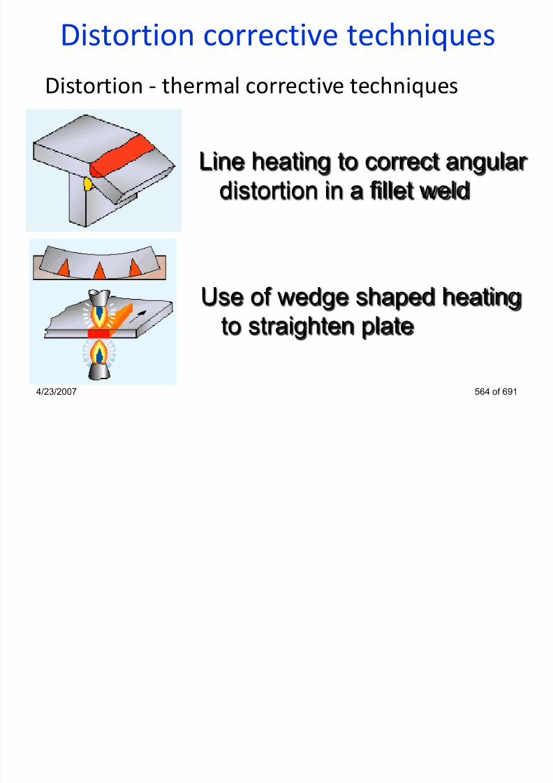
7/22/2019 weldinginspectioncswip-100402035204-phpapp02
http://slidepdf.com/reader/full/weldinginspectioncswip-100402035204-phpapp02 520/636
4/23/2007 564 of 691
Use of wedge shaped heating
to straighten plate
Distortion corrective techniques
Distortion - thermal corrective techniques
Wedge shaped heating to correct distortion
a) standard rolled b) buckled edge of c) box fabrication
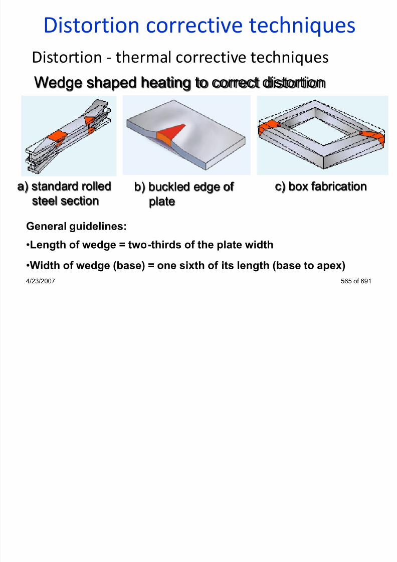
7/22/2019 weldinginspectioncswip-100402035204-phpapp02
http://slidepdf.com/reader/full/weldinginspectioncswip-100402035204-phpapp02 521/636
4/23/2007 565 of 691
)steel section
) gplate
)
General guidelines:
•Length of wedge = two-thirds of the plate width
•Width of wedge (base) = one sixth of its length (base to apex)
Distortion corrective techniques
Distortion - thermal corrective techniques
•use spot heating to remove buckling in thin sheet structures
•other than in spot heating of thin panels, use a wedge-shapedheating technique
•use line heating to correct angular distortion in plate
•restrict the area of heating to avoid over-shrinking the component
•limit the temperature to 60° to 650°C (dull red heat) in steels toprevent metallurgical damage

7/22/2019 weldinginspectioncswip-100402035204-phpapp02
http://slidepdf.com/reader/full/weldinginspectioncswip-100402035204-phpapp02 522/636
4/23/2007 566 of 691
prevent metallurgical damage
•in wedge heating, heat from the base to the apex of the wedge,
penetrate evenly through the plate thickness and maintain an even
temperature
Welding Inspector
Heat Treatment
Section 18

7/22/2019 weldinginspectioncswip-100402035204-phpapp02
http://slidepdf.com/reader/full/weldinginspectioncswip-100402035204-phpapp02 523/636
4/23/2007 567 of 691
Heat Treatment
Why?
Improve mechanical properties
Change microstructure
Reduce residual stress level
Change chemical composition
How?
Flame ovenElectric oven/electric heating blankets

7/22/2019 weldinginspectioncswip-100402035204-phpapp02
http://slidepdf.com/reader/full/weldinginspectioncswip-100402035204-phpapp02 524/636
4/23/2007 568 of 691
Electric oven/electric heating blankets
induction/HF heating elements
Where? LocalGlobal
Heat TreatmentsMany metals must be given heat treatment before and afterwelding.
The inspector’s function is to ensure that the treatment isgiven correctly in accordance with the specification or as per
the details supplied.Types of heat treatment available:
•Preheat
•Annealing

7/22/2019 weldinginspectioncswip-100402035204-phpapp02
http://slidepdf.com/reader/full/weldinginspectioncswip-100402035204-phpapp02 525/636
4/23/2007 569 of 691
g•Normalising
•Quench Hardening
•Temper
•Stress Relief
Heat TreatmentsPre-heat treatments
• are used to increase weldability, by reducing sudden
reduction of temperature, and control expansion and
contraction forces during welding
Post weld heat treatments
d t h th ti f th ld t l

7/22/2019 weldinginspectioncswip-100402035204-phpapp02
http://slidepdf.com/reader/full/weldinginspectioncswip-100402035204-phpapp02 526/636
• are used to change the properties of the weld metal,
controlling the formation of crystalline structures
4/23/2007 570 of 691
Post Weld -Heat Treatments
Post Hydrogen Release (according to BS EN1011-2)
Temperature: Approximately 250 C hold up to 3 hours
Cooling: Slow cool in air
Result: Relieves residual hydrogen
Procedure: Maintaining pre-heat / interpass temperature after
completion of welding for 2 to 3 hours.

7/22/2019 weldinginspectioncswip-100402035204-phpapp02
http://slidepdf.com/reader/full/weldinginspectioncswip-100402035204-phpapp02 527/636
4/23/2007 571 of 691
Post Weld Heat Treatments
(A) Normalised
(B) Fully Annealed(C) Water-quenched
(D) Water-quenched & tempered
A B
C D

7/22/2019 weldinginspectioncswip-100402035204-phpapp02
http://slidepdf.com/reader/full/weldinginspectioncswip-100402035204-phpapp02 528/636
4/23/2007 572 of 691
Post Weld Heat Treatments
The inspector, in general, should ensure that:
• Equipment is as specified
• Temperature control equipment is in good condition
• Procedures as specified, is being used e.g.
o Method of application
o Rate of heating and cooling

7/22/2019 weldinginspectioncswip-100402035204-phpapp02
http://slidepdf.com/reader/full/weldinginspectioncswip-100402035204-phpapp02 529/636
o Maximum temperature
o Soak time
o Temperature measurement (and calibration)
• DOCUMENTATION AND RECORDS4/23/2007 573 of 691
Post Weld Heat Treatment Cycle
TemperatureSoakingTemperature
and time at the
attained temperature
heating rate Cooling rate
Variables for heat treatment process must be carefully controlled

7/22/2019 weldinginspectioncswip-100402035204-phpapp02
http://slidepdf.com/reader/full/weldinginspectioncswip-100402035204-phpapp02 530/636
Time
4/23/2007 575 of 691
Heating Soaking Cooling
Post Weld Heat TreatmentRemoval of Residual Stress
Yield
Strength
(N/mm
2
)
100
200
300
400
500Cr-Mo steel - typical
C-Mn steel - typical
• At PWHT temp. the yield
strength of steel reduced
so that it it is not strong
enough to give restraint.
• Residual stress reduced
to very low level by
straining (typ ical ly < ~
0.5% s train)

7/22/2019 weldinginspectioncswip-100402035204-phpapp02
http://slidepdf.com/reader/full/weldinginspectioncswip-100402035204-phpapp02 531/636
4/23/2007 576 of 691
Temperature (°C)
100 200 300 400 500 600 700
Heat Treatment
Recommendations
• Provide adequate support (low YS at high temperature!)
•Control heating rate to avoid uneven thermal expansions
• Control soak time to equalise temperatures
• Control temperature gradients - NO direct flame impingement!
• Control furnace atmosphere to reduce scalingC l li id b i l f i
7/22/2019 weldinginspectioncswip-100402035204-phpapp02
http://slidepdf.com/reader/full/weldinginspectioncswip-100402035204-phpapp02 532/636
• Control cooling rate to avoid brittle structure formation
4/23/2007 577 of 691
Post Weld Heat Treatment Methods
Advantages:
Easy to set up
Good portability
repeatability and
temperature uniformity

7/22/2019 weldinginspectioncswip-100402035204-phpapp02
http://slidepdf.com/reader/full/weldinginspectioncswip-100402035204-phpapp02 533/636
Gas furnace heat treatment
4/23/2007 578 of 691
Disadvantages:
Limited to size of parts
Post Weld Heat Treatment Methods
Advantages:
High heating rates
Ability to heat anarrow band
Disadvantages:
High equipment

7/22/2019 weldinginspectioncswip-100402035204-phpapp02
http://slidepdf.com/reader/full/weldinginspectioncswip-100402035204-phpapp02 534/636
HF (Induction) local heat treatment
4/23/2007 579 of 691
cost
Large equipment,
less portable
Post Weld Heat Treatment Methods
Advantages:
Ability to vary
heat Ability to
continuously
maintain heat
Disadvantages:

7/22/2019 weldinginspectioncswip-100402035204-phpapp02
http://slidepdf.com/reader/full/weldinginspectioncswip-100402035204-phpapp02 535/636
Local heat treatment usingelectric heating blankets
4/23/2007 580 of 691
Disadvantages:
Elements may
burn out or arcing
during heating
Welding Inspector
Cutting Processes
Section 19

7/22/2019 weldinginspectioncswip-100402035204-phpapp02
http://slidepdf.com/reader/full/weldinginspectioncswip-100402035204-phpapp02 536/636
4/23/2007 581 of 691
Use of gas flame
Welding GougingBrazing Cutting

7/22/2019 weldinginspectioncswip-100402035204-phpapp02
http://slidepdf.com/reader/full/weldinginspectioncswip-100402035204-phpapp02 537/636
4/23/2007 582 of 691
Heating Straightening Blasting Spraying
Regulators
Oxygen regulator Fuel gas regulator
Single stage used when slight rise in deliverypressure from full to empty cylinder

7/22/2019 weldinginspectioncswip-100402035204-phpapp02
http://slidepdf.com/reader/full/weldinginspectioncswip-100402035204-phpapp02 538/636
4/23/2007 583 of 691
Regulatortype
Two stage
pressure from full to empty cylinder
condition can be tolerated
used when a constant delivery
pressure from full to empty
cylinder condition is required
Flashback arrestors
Flashback - recession of the flame into or back of the mixing chamber
Flashback
flame
quenched
at the
fl hb k
Flame
barrie
r
Built-
in
check
valve
Normal
flow
Reverse
flow
Flashback
Built-in
check
valve
stops
reverseflow
SAFETY SAFETY SAFETY

7/22/2019 weldinginspectioncswip-100402035204-phpapp02
http://slidepdf.com/reader/full/weldinginspectioncswip-100402035204-phpapp02 539/636
4/23/2007 584 of 691
flashback
barrier
r flow
A jet of pure oxygen reacts with iron, that has beenpreheated to its ignition point, to produce theoxide Fe3O4 by exothermic reaction.This oxide isthen blown through the material by the velocity ofthe oxygen stream
Different types of fuel gases may be used for thepre-heating flame in oxy fuel gas cutting: i.e.acetylene, hydrogen, propane. etc
By adding iron powder to the flame we are able
to cut most metals - “Iron Powder Injection”
Oxyfuel gas cutting process

7/22/2019 weldinginspectioncswip-100402035204-phpapp02
http://slidepdf.com/reader/full/weldinginspectioncswip-100402035204-phpapp02 540/636
4/23/2007 585 of 691
The high intensity of heat and rapid cooling willcause hardening in low alloy and medium/high Csteels they are thus pre-heated to avoid thehardening effect
Oxyfuel gas cutting equipment
The cutting torch

7/22/2019 weldinginspectioncswip-100402035204-phpapp02
http://slidepdf.com/reader/full/weldinginspectioncswip-100402035204-phpapp02 541/636
4/23/2007 586 of 691
Neutral cutting flame
Neutral cutting flame withoxygen cutting stream
Oxyfuel gas cutting related terms

7/22/2019 weldinginspectioncswip-100402035204-phpapp02
http://slidepdf.com/reader/full/weldinginspectioncswip-100402035204-phpapp02 542/636
4/23/2007 587 of 691
Oxyfuel gas cutting quality
• Good cut - sharp top edge, fine and even drag lines, littleoxide and a sharp bottom edge

7/22/2019 weldinginspectioncswip-100402035204-phpapp02
http://slidepdf.com/reader/full/weldinginspectioncswip-100402035204-phpapp02 543/636
4/23/2007 588 of 691
Cut too fast -pronounced break in
the drag line,irregular cut edge
Cut too slow - top edge ismelted, deep groves in thelower portion, heavy scaling,rough bottom edge
Oxyfuel gas cutting quality
• Good cut - sharp top edge, fine and even drag lines, littleoxide and a sharp bottom edge
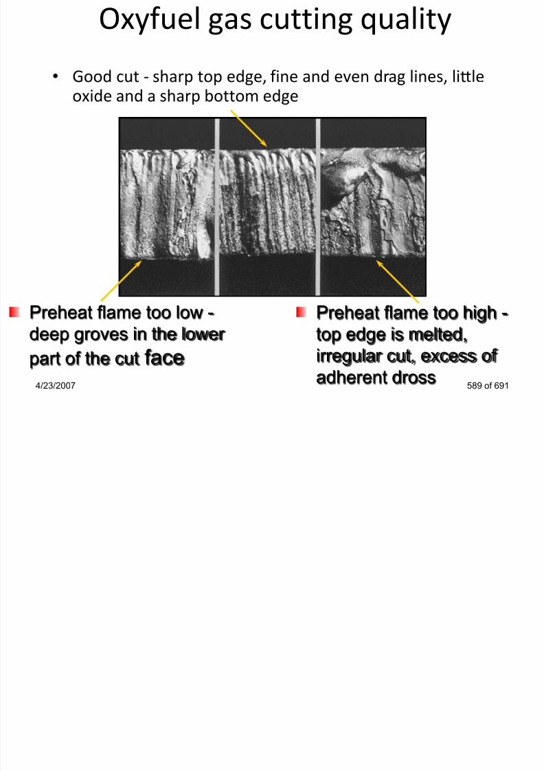
7/22/2019 weldinginspectioncswip-100402035204-phpapp02
http://slidepdf.com/reader/full/weldinginspectioncswip-100402035204-phpapp02 544/636
4/23/2007 589 of 691
Preheat flame too high -
top edge is melted,
irregular cut, excess of
adherent dross
Preheat flame too low -
deep groves in the lower
part of the cut face
Oxyfuel gas cutting quality
• Good cut - sharp top edge, fine and even drag lines, littleoxide and a sharp bottom edge

7/22/2019 weldinginspectioncswip-100402035204-phpapp02
http://slidepdf.com/reader/full/weldinginspectioncswip-100402035204-phpapp02 545/636
4/23/2007 590 of 691
Irregular travel speed - uneven
space between drag lines,
irregular bottom with adherent
oxide
Nozzle is too high abovethe works - excessivemelting of the top edge,
much oxide
Mechanised oxyfuel cutting
• can use portable carriages or gantry type machines and
obtain high productivity
• accurate cutting for complicate shapes
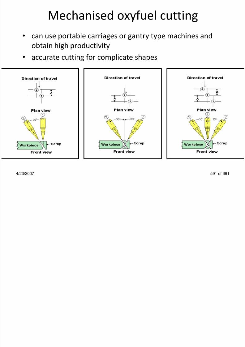
7/22/2019 weldinginspectioncswip-100402035204-phpapp02
http://slidepdf.com/reader/full/weldinginspectioncswip-100402035204-phpapp02 546/636
4/23/2007 591 of 691
OFW/C advantages/disadvantages
Disadvantages:
1) High skill factor
2) Wide HAZ
4) Slow process
5) Limited range ofconsumables
3) Safety issues
Advantages:
1) No need for powersupply, portable
3) Low equipment cost
2) Versatile: preheat,brazing, surfacing, repair,straightening

7/22/2019 weldinginspectioncswip-100402035204-phpapp02
http://slidepdf.com/reader/full/weldinginspectioncswip-100402035204-phpapp02 547/636
4/23/2007 592 of 691
consumables4) Can cut carbon and lowalloy steels
5) Good on thin materials
6) Not suitable for reactive& refractory metals
Special oxyfuel operations
• Gouging Rivet cutting

7/22/2019 weldinginspectioncswip-100402035204-phpapp02
http://slidepdf.com/reader/full/weldinginspectioncswip-100402035204-phpapp02 548/636
4/23/2007 593 of 691
Special oxyfuel operations
• Thin sheet cutting Rivet washing
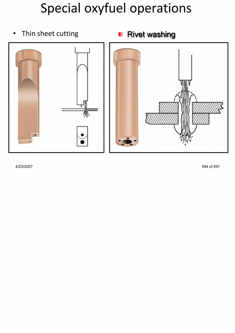
7/22/2019 weldinginspectioncswip-100402035204-phpapp02
http://slidepdf.com/reader/full/weldinginspectioncswip-100402035204-phpapp02 549/636
4/23/2007 594 of 691
Cutting ProcessesPlasma arc cutting
• Uses high velocity jet of ionised gas through a
constricted nozzle to remove the molten
metal
• Uses a tungsten electrode and water cooled
nozzle

7/22/2019 weldinginspectioncswip-100402035204-phpapp02
http://slidepdf.com/reader/full/weldinginspectioncswip-100402035204-phpapp02 550/636
• High quality cutting
• High intensity and UV radiation – EYES !
4/23/2007 595 of 691
Cutting Processes
Air-arc for cutting or gouging

7/22/2019 weldinginspectioncswip-100402035204-phpapp02
http://slidepdf.com/reader/full/weldinginspectioncswip-100402035204-phpapp02 551/636
4/23/2007 596 of 691
Air-arc gouging features
• Operate ONLY on DCEP
• Special gouging copper
coated carbon electrode
• Can be used on carbonand low alloy steels,
austenitic stainless steels
and non-ferrous materials
• Requires CLEAN/DRY
compressed air supply
• Provides fast rate of metal removal

7/22/2019 weldinginspectioncswip-100402035204-phpapp02
http://slidepdf.com/reader/full/weldinginspectioncswip-100402035204-phpapp02 552/636
4/23/2007 597 of 691
• Can remove complex shape defects
• After gouging, grinding of carbured layer is mandatory
• Gouging doesn‟t require a qualified welder!
Welding InspectorArc Welding Safety
Please discussSection 20

7/22/2019 weldinginspectioncswip-100402035204-phpapp02
http://slidepdf.com/reader/full/weldinginspectioncswip-100402035204-phpapp02 553/636
4/23/2007 598 of 691
Safety
• Electrical safety
• Heat & Light – Visible light
– UV radiation - effects on skinand eyes
• Fumes & Explosive Gasses
• Noise levels
• Fire Hazards
• Scaffolding & Staging
• Slips trips and falls

7/22/2019 weldinginspectioncswip-100402035204-phpapp02
http://slidepdf.com/reader/full/weldinginspectioncswip-100402035204-phpapp02 554/636
• Slips, trips and falls
• Protection of others fromexposure
4/23/2007 599 of 691
Welding InspectorWeldability Of Steels
Section 21

7/22/2019 weldinginspectioncswip-100402035204-phpapp02
http://slidepdf.com/reader/full/weldinginspectioncswip-100402035204-phpapp02 555/636
4/23/2007 600 of 691
Weldability of Steels
Definition
It relates to the ability of the metal (or alloy) to be welded with
mechanical soundness by most of the common welding processes,
and the resulting welded joint retain the properties for which it
has been designed.
is a function of many inter-related factors but these may be
summarised as:
•Composition of parent material
•Joint design and size

7/22/2019 weldinginspectioncswip-100402035204-phpapp02
http://slidepdf.com/reader/full/weldinginspectioncswip-100402035204-phpapp02 556/636
•Joint design and size
•Process and technique
•Access
4/23/2007 601 of 691
Weldability of SteelsThe weldability of steel is mainly dependant on carbon & other alloyingelements content.
If a material has limited weldability, we need to take special measures to
ensure the maintenance of the properties required
Poor weldability normally results in the occurrence of cracking
A steel is considered to have poor weldability when:
• an acceptable joint can only be made by using very narrow range ofwelding conditions
7/22/2019 weldinginspectioncswip-100402035204-phpapp02
http://slidepdf.com/reader/full/weldinginspectioncswip-100402035204-phpapp02 557/636
• great precautions to avoid cracking are essential (e.g., high pre-heat etc)
4/23/2007 602 of 691
The Effect of Alloying on Steels
Elements may be added to steels to produce the propertiesrequired to make it useful for an application.
Most elements can have many effects on the properties ofsteels.
Other factors which affect material properties are:
•The temperature reached before and during welding
•Heat input
•The cooling rate after welding and or PWHT

7/22/2019 weldinginspectioncswip-100402035204-phpapp02
http://slidepdf.com/reader/full/weldinginspectioncswip-100402035204-phpapp02 558/636
The cooling rate after welding and or PWHT
4/23/2007 603 of 691
Steel Alloying Elements
Iron (Fe): Main steel constituent. On its own, is relatively soft, ductile, with low
strength.
Carbon (C): Major alloying element in steels, a strengthening element with
major influence on HAZ hardness. Decreases weldability.
•typically < ~ 0.25%
Manganese (Mn): Secondary only to carbon for strength, toughness and
ductility, secondary de-oxidiser and also reacts with sulphur to form
manganese sulphide.
< ~0.8% is residual from steel de-oxidation

7/22/2019 weldinginspectioncswip-100402035204-phpapp02
http://slidepdf.com/reader/full/weldinginspectioncswip-100402035204-phpapp02 559/636
4/23/2007 604 of 691
•up to ~1.6% (in C-Mn steels) improves strength & toughness
Silicon (Si): Residual element from steel de-oxidation.
•typically to ~0.35%
Steel Alloying Elements
Phosphorus (P): Residual element from steel-making minerals. difficult to reducebelow < ~ 0.015% brittleness
Sulphur (S): Residual element from steel-making minerals
< ~ 0.015% in modern steels
< ~ 0.003% in very clean steels
Aluminium (Al): De-oxidant and grain size control
•typically ~ 0.02 to ~ 0.05%
Chromium (Cr): For creep resistance & oxidation (scaling) resistance for elevated

7/22/2019 weldinginspectioncswip-100402035204-phpapp02
http://slidepdf.com/reader/full/weldinginspectioncswip-100402035204-phpapp02 560/636
temperature service. Widely used in stainless steels for corrosion resistance,
increases hardness and strength but reduces ductility.
•typically ~ 1 to 9% in low alloy steels
4/23/2007 605 of 691
Nickel (Ni): Used in stainless steels, high resistance to corrosion from acids,
increases strength and toughness
Molybdenum (Mo): Affects hardenability. Steels containing molybdenum
are less susceptible to temper brittleness than other alloy steels.Increases the high temperature tensile and creep strengths of steel.typically ~ 0.5 to 1.0%
Niobium (Nb): a grain refiner, typically~ 0.05%
Vanadium (V): a grain refiner, typically ~ 0.05%
Titanium (Ti): a grain refiner typically ~ 0 05%
Steel Al loy ing Elements

7/22/2019 weldinginspectioncswip-100402035204-phpapp02
http://slidepdf.com/reader/full/weldinginspectioncswip-100402035204-phpapp02 561/636
Titanium (Ti): a grain refiner, typically 0.05%
Copper (Cu): present as a residual, (typically < ~ 0.30%)
added to ‘weathering steels’ (~ 0.6%) to give better resistance to
atmospheric corrosion
4/23/2007 606 of 691
Classification of Steels
Mild steel (CE < 0.4)
• Readily weldable, preheat generally not required if low hydrogenprocesses or electrodes are used
• Preheat may be required when welding thick section material, high
restraint and with higher levels of hydrogen being generated
C-Mn, medium carbon, low alloy steels (CE 0.4 to 0.5)
• Thin sections can be welded without preheat but thicker sections willrequire low preheat levels and low hydrogen processes or electrodes
should be used

7/22/2019 weldinginspectioncswip-100402035204-phpapp02
http://slidepdf.com/reader/full/weldinginspectioncswip-100402035204-phpapp02 562/636
Higher carbon and alloyed steels (CE > 0.5)
• Preheat, low hydrogen processes or electrodes, post weld heating andslow cooling may be required
4/23/2007 607 of 691
Process Cracks
• Hydrogen Induced HAZ Cracking (C/Mn steels)
• Hydrogen Induced Weld Metal Cracking (HSLA steels).
• Solidification or Hot Cracking (All steels)
• Lamellar Tearing (All steels)
• Re-heat Cracking (All steels, very susceptible Cr/Mo/V steels)
I t C t lli C i W ld D ( t i l t l )

7/22/2019 weldinginspectioncswip-100402035204-phpapp02
http://slidepdf.com/reader/full/weldinginspectioncswip-100402035204-phpapp02 563/636
• Inter-Crystalline Corrosion or Weld Decay (stainless steels)
4/23/2007 608 of 691
CrackingWhen considering any type of cracking mechanism, threeelements must always be present:
• Stress
Residual stress is always present in a weldment, throughunbalanced local expansion and contraction
• Restraint
Restraint may be a local restriction, or through platesbeing welded to each other
• Susceptible microstructure

7/22/2019 weldinginspectioncswip-100402035204-phpapp02
http://slidepdf.com/reader/full/weldinginspectioncswip-100402035204-phpapp02 564/636
• Susceptible microstructure
The microstructure may be made susceptible tocracking by the process of welding
4/23/2007 609 of 691
Cracks
Hydrogen Induced Cold Cracking
7/22/2019 weldinginspectioncswip-100402035204-phpapp02
http://slidepdf.com/reader/full/weldinginspectioncswip-100402035204-phpapp02 565/636
4/23/2007 610 of 691
Hydrogen Induced Cold Cracking
May occur:
• up to 48 hrs after completion
• In weld metal, HAZ, parentmetal.
• At weld toes
• Under weld beads
• At stress raisers.
Also know as:
Cold Cracking, happens when
the welds cool down.
HAZ cracking, normally occurs
in the HAZ.
Delayed cracking, as it takes
time for the hydrogen to
migrate. 48 Hours normally but
up to 72

7/22/2019 weldinginspectioncswip-100402035204-phpapp02
http://slidepdf.com/reader/full/weldinginspectioncswip-100402035204-phpapp02 566/636
4/23/2007 611 of 691
up to 72,
Under-bead cracking, normally
happens in the HAZ under aweld bead
Hydrogen Induced Cold Cracking
There is a risk of hydrogen cracking when all of the 4 factors
occur together:
•Hydrogen More than 15ml/100g of weld metal•Stress More than ½ the yield stress
•Temperature Below 300oC
•Hardness Greater than 400HV Vickers

7/22/2019 weldinginspectioncswip-100402035204-phpapp02
http://slidepdf.com/reader/full/weldinginspectioncswip-100402035204-phpapp02 567/636
•Susceptible Microstructure (Martensite)
4/23/2007 612 of 691
Hydrogen Induced Cold Cracking

7/22/2019 weldinginspectioncswip-100402035204-phpapp02
http://slidepdf.com/reader/full/weldinginspectioncswip-100402035204-phpapp02 568/636
4/23/2007 613 of 691
Hydrogen Induced Cold Cracking
Precautions for controlling hydrogen cracking
• Pre heat, removes moisture from the joint preparations, and
slows down the cooling rate
• Ensure joint preparations are clean and free fromcontamination
• The use of a low hydrogen welding process and correct arc
length
• Ensure all welding is carried out is carried out under controlledenvironmental conditions

7/22/2019 weldinginspectioncswip-100402035204-phpapp02
http://slidepdf.com/reader/full/weldinginspectioncswip-100402035204-phpapp02 569/636
• Ensure good fit-up as to reduced stress
• The use of a PWHT
• Avoid poor weld profiles4/23/2007 614 of 691
Hydrogen Induced Cold Cracking
• Hydrogen is the smallest atom known
• Hydrogen enters the weld via the arc
• Source of hydrogen mainly from moisture pick-up onthe electrodes coating, welding fluxes or from the
consumable gas
HH2
Moisture onthe electrodeor grease on
Water vapourin the air ori th

7/22/2019 weldinginspectioncswip-100402035204-phpapp02
http://slidepdf.com/reader/full/weldinginspectioncswip-100402035204-phpapp02 570/636
4/23/2007 615 of 691
H2
H2
H2H2
or grease onthe wirein the
shielding gas
Oxide or grease on
the plate
Hydrogen absorbed
in a long, or
unstable arc
Hydrogen introduced in
weld from consumable,
oils, or paint on plate
Cellulosic electrodes
produce hydrogen as a
shielding gas
Hydrogen
crack
H2H2
Hydrogen Induced Cold Crack ing

7/22/2019 weldinginspectioncswip-100402035204-phpapp02
http://slidepdf.com/reader/full/weldinginspectioncswip-100402035204-phpapp02 571/636
4/23/2007 616 of 691
Martensite forms from γ H2 diffuses to γ in HAZ
22
Hydrogen Induced Cold Cracking
Susceptible Microstructure:
Hard brittle structure – MARTENSITE Promoted by:
A) High Carbon Content, Carbon Equivalent (CE)
CEV = %C + Mn + Cr+Mo+V + Ni+Cu
6 5 15B) high alloy content
C) fast cooling rate: Inadequate Pre-Heating
Cold MaterialThick Material
L H t I t
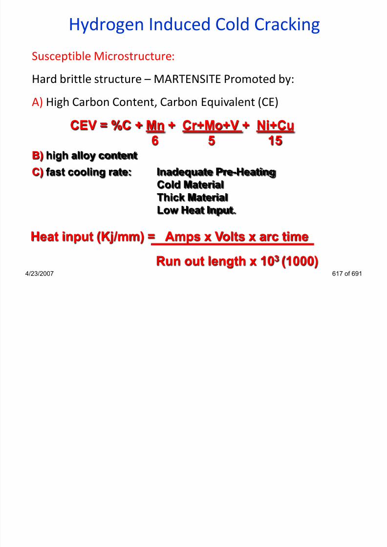
7/22/2019 weldinginspectioncswip-100402035204-phpapp02
http://slidepdf.com/reader/full/weldinginspectioncswip-100402035204-phpapp02 572/636
4/23/2007 617 of 691
Heat input (Kj/mm) = Amps x Volts x arc time
Run out length x 103 (1000)
Low Heat Input.
Hydrogen Induced Cold Cracking

7/22/2019 weldinginspectioncswip-100402035204-phpapp02
http://slidepdf.com/reader/full/weldinginspectioncswip-100402035204-phpapp02 573/636
Typical locations for Cold Cracking4/23/2007 618 of 691
•HSLA or Micro-Alloyed Steels are high strength steels
(800MPa/N/mm2) that derive their high strength from small
percentage alloying (over-alloyed Weld metal to match the
strength of parent metal)
•Typically the level of alloying is in the elements such asvanadium molybdenum and titanium, nickel and chromium
Strength. are used. It would be impossible to match this micro
alloying in the electrode due to the effect of losses across an
electric arc (Ti burn in the arc)
•It is however important to match the strength of the weld to
the strength of the plate, Mn 1.6 Cr Ni Mo
HICC in HSLA steels

7/22/2019 weldinginspectioncswip-100402035204-phpapp02
http://slidepdf.com/reader/full/weldinginspectioncswip-100402035204-phpapp02 574/636
4/23/2007 619 of 691
Hydrogen Scales
List of hydrogen scales from BS EN 1011:part 2.
Hydrogen content related to 100 grams of weld metal
deposited.
• Scale A High: >15 ml
• Scale B Medium: 10 ml - 15 ml
• Scale C Low: 5 ml - 10 ml

7/22/2019 weldinginspectioncswip-100402035204-phpapp02
http://slidepdf.com/reader/full/weldinginspectioncswip-100402035204-phpapp02 575/636
• Scale D Very low: 3 ml - 5 ml
• Scale E Ultra-low: < 3 ml
4/23/2007 621 of 691
Potential Hydrogen Level Processes
list of welding processes in order of potential lowest hydrogen
content with regards to 100g of deposited weld metal.
•TIG < 3 ml
•MIG < 5 ml
•ESW < 5 ml
•MMA (Basic Electrodes) < 5 ml
•SAW < 10ml

7/22/2019 weldinginspectioncswip-100402035204-phpapp02
http://slidepdf.com/reader/full/weldinginspectioncswip-100402035204-phpapp02 576/636
•SAW < 10ml
•FCAW < 15 ml
4/23/2007 622 of 691
Weldability
Solidification Cracking

7/22/2019 weldinginspectioncswip-100402035204-phpapp02
http://slidepdf.com/reader/full/weldinginspectioncswip-100402035204-phpapp02 577/636
4/23/2007 623 of 691
Solidification Cracking

7/22/2019 weldinginspectioncswip-100402035204-phpapp02
http://slidepdf.com/reader/full/weldinginspectioncswip-100402035204-phpapp02 578/636
4/23/2007 624 of 691
Usually Occurs in Weld Centerline
Solidification CrackingAlso referred as
Hot Cracking: Occurring at high temperatures while the weld is hot
Centerline cracking: cracks appear down the centre line of the bead.
Crater cracking: Small cracks in weld centers are solidification cracks
Crack type: Solidification cracking
Location: Weld centreline (longitudinal)
Steel types: High sulphur & phosphor concentration in steels.

7/22/2019 weldinginspectioncswip-100402035204-phpapp02
http://slidepdf.com/reader/full/weldinginspectioncswip-100402035204-phpapp02 579/636
Susceptible Microstructure: Columnar grains In direction
of solidification
4/23/2007 625 of 691
Solidification Cracking
Factors for solidification cracking
• Columnar grain growth with impurities in weld metal (sulphur,
phosphor and carbon)
• The amount of stress/restraint
• Joint design high depth to width ratios
Liquid iron sulphides are formed around solidifying grains.
High contractional strains are present
High dilution processes are being used.

7/22/2019 weldinginspectioncswip-100402035204-phpapp02
http://slidepdf.com/reader/full/weldinginspectioncswip-100402035204-phpapp02 580/636
4/23/2007 626 of 691
There is a high carbon content in the weld metal
• Most commonly occurring in sub-arc welded joints
Solidification Cracking
• Sulphur in the parent material may dilute in the weld
metal to form iron sulphides (low strength, low melting
point compounds)
• During weld metal solidification, columnar crystals pushstill liquid iron sulphides in front to the last place of
solidification, weld centerline.
• The bonding between the grains which are themselves
under great stress and may now be very poor to maintain
cohesion and a crack will result, weld centerline.

7/22/2019 weldinginspectioncswip-100402035204-phpapp02
http://slidepdf.com/reader/full/weldinginspectioncswip-100402035204-phpapp02 581/636
4/23/2007 627 of 691
Solidification Cracking
Avoidance
Deep, narrower weld bead
On solidification thebonding between the grains
may now be very poor to
Shallow, wider weld bead
On solidification thebonding between the
grains may be adequate to
HAZ HAZ
Intergranular liquid filmColumnargrains Columnar
grains

7/22/2019 weldinginspectioncswip-100402035204-phpapp02
http://slidepdf.com/reader/full/weldinginspectioncswip-100402035204-phpapp02 582/636
4/23/2007 628 of 691
may now be very poor to
maintain cohesion and a
crack may result
g y q
maintain cohesion and a
crack is unlikely to occur
Solidification Cracking
Precautions for controlling solidification cracking
•The first steps in eliminating this problem would be to choose a low
dilution process, and change the joint design
Grind and seal in any lamination and avoid further dilution???? Add Manganese to the electrode to form spherical Mn/S which form
between the grain and maintain grain cohesion
As carbon increases the Mn/S ratio required increases
exponentially and is a major factor. Carbon content % should be aminimised by careful control in electrode and dilution
Limit the heat input hence low contraction & minimise restraint

7/22/2019 weldinginspectioncswip-100402035204-phpapp02
http://slidepdf.com/reader/full/weldinginspectioncswip-100402035204-phpapp02 583/636
4/23/2007 629 of 691
Limit the heat input, hence low contraction, & minimise restraint
Solidification Cracking
Precautions for controlling solidification cracking
• The use of high manganese and low carbon content fillers
• Minimise the amount of stress / restraint acting on the jointduring welding
• The use of high quality parent materials, low levels of
impurities (Phosphor & sulphur)
• Clean joint preparations contaminants (oil, grease, paints and
any other sulphur containing product)

7/22/2019 weldinginspectioncswip-100402035204-phpapp02
http://slidepdf.com/reader/full/weldinginspectioncswip-100402035204-phpapp02 584/636
y p g p )
• Joint design selection depth to width ratios
4/23/2007 630 of 691
Solidification Cracking
Solidification cracking in Austenitic Stainless Steel
• particularly prone to solidification cracking
• large grain size gives rise to a reduction in grain boundary area with
high concentration of impurities
• Austenitic structure very intolerant to contaminants (sulphur,
phosphorous and other impurities).
• High coefficient of thermal expansion /Low coefficient of thermalconductivity, with high resultant residual stress

7/22/2019 weldinginspectioncswip-100402035204-phpapp02
http://slidepdf.com/reader/full/weldinginspectioncswip-100402035204-phpapp02 585/636
• same precautions against cracking as for plain carbon steels with extra
emphasis on thorough cleaning and high dilution controls.
4/23/2007 631 of 691
Cracks
Lamellar Tearing
7/22/2019 weldinginspectioncswip-100402035204-phpapp02
http://slidepdf.com/reader/full/weldinginspectioncswip-100402035204-phpapp02 586/636
4/23/2007 632 of 691
Lamellar Tearing
Factors for lamellar tearing to occur
Cracks only occur in the rolled plate !
Close to or just outside the HAZ !
Cracks lay parallel to the plate surface and the fusion boundaryof the weld and has a stepped aspect.
• Low quality parent materials, high levels of impurities
• Joint design, direction of stress
• The amount of stress acting across the joint during welding

7/22/2019 weldinginspectioncswip-100402035204-phpapp02
http://slidepdf.com/reader/full/weldinginspectioncswip-100402035204-phpapp02 587/636
The amount of stress acting across the joint during welding
• Note: very susceptible joints may form lamellar tearing under
very low levels of stress
4/23/2007 633 of 691
Lamellar Tearing
Susceptible joint types combined with susceptible rolled plateused to make a joint.
High stresses act in the through thickness direction of the plate
(know as the short transverse direction).
T, K & Y joints normally end up with a tensile residual stress
component in the through thickness direction.

7/22/2019 weldinginspectioncswip-100402035204-phpapp02
http://slidepdf.com/reader/full/weldinginspectioncswip-100402035204-phpapp02 588/636
4/23/2007 634 of 691
Tee fillet weld Tee butt weld(double-bevel)
Corner butt weld(single-bevel)
Lamellar Tearing
Critical area
Critical
area
Critical area

7/22/2019 weldinginspectioncswip-100402035204-phpapp02
http://slidepdf.com/reader/full/weldinginspectioncswip-100402035204-phpapp02 589/636
4/23/2007 635 of 691
Lamellar Tearing
Modifying a corner joint to avoid lamellar tearing
Susceptible Non-Susceptible
Prior welding both An open corner joint

7/22/2019 weldinginspectioncswip-100402035204-phpapp02
http://slidepdf.com/reader/full/weldinginspectioncswip-100402035204-phpapp02 590/636
4/23/2007 636 of 691
Prior welding bothplates may be groovedto avoid lamellar tearing
An open corner jointmay be selected toavoid lamellar tearing
Lamellar Tearing
Precautions for controlling lamellar tearing
• The use of high quality parent materials, low levels of
impurities
• The use of buttering runs
• A gap can be left between the horizontal and vertical
members enabling the contraction movement to take
place
• Joint design selection
Minimise the amount of stress / restraint acting on the

7/22/2019 weldinginspectioncswip-100402035204-phpapp02
http://slidepdf.com/reader/full/weldinginspectioncswip-100402035204-phpapp02 591/636
4/23/2007 637 of 691
• Minimise the amount of stress / restraint acting on the
joint during welding
• Hydrogen precautions
Lamellar TearingCrack type: Lamellar tearing
Location: Below weld HAZ
Steel types: High sulphur & phosphorous steels
Microstructure: Lamination & Segregation
Occurs when:
High contractional strains are through the short
transverse direction. There is a high sulfur content inthe base metal.
Th i l th h thi k d tilit i th b

7/22/2019 weldinginspectioncswip-100402035204-phpapp02
http://slidepdf.com/reader/full/weldinginspectioncswip-100402035204-phpapp02 592/636
4/23/2007 638 of 691
There is low through thickness ductility in the base
metal.
There is high restraint on the work
Short Tensile (Through Thickness) Test
The short tensile test or through thickness test is a
test to determine a materials susceptibility to
lamellar tearing
Friction Welded Caps
Short Tensile Specimen
ThroughThickness
Ductility
Sample of Parent Material

7/22/2019 weldinginspectioncswip-100402035204-phpapp02
http://slidepdf.com/reader/full/weldinginspectioncswip-100402035204-phpapp02 593/636
4/23/2007 639 of 691
The results are given as a STRA value
Short Transverse Reduction in Area
Restraint
Lamellar Tearing

7/22/2019 weldinginspectioncswip-100402035204-phpapp02
http://slidepdf.com/reader/full/weldinginspectioncswip-100402035204-phpapp02 594/636
4/23/2007 640 of 691
High contractional
strains
Lamellar tear
Welding Inspector
Practical Visual Inspection
Section 22

7/22/2019 weldinginspectioncswip-100402035204-phpapp02
http://slidepdf.com/reader/full/weldinginspectioncswip-100402035204-phpapp02 595/636
4/23/2007 641 of 691
Leg Length Gauge
G.A.L.
S.T.D.
10mm
16mm
L
G.A.L.
S.T.D.
10mm
Fillet Weld Gauges

7/22/2019 weldinginspectioncswip-100402035204-phpapp02
http://slidepdf.com/reader/full/weldinginspectioncswip-100402035204-phpapp02 596/636
4/23/2007 642 of 691
Throat Thickness Gauge
16mm
S i n g l e P u r p
o s e W e l d i n g G a u g e
1
2
3
4
5
6
Root gapdimension
Internal
alignment
HI-LO Welding Gauge

7/22/2019 weldinginspectioncswip-100402035204-phpapp02
http://slidepdf.com/reader/full/weldinginspectioncswip-100402035204-phpapp02 597/636
4/23/2007 643 of 691
H I - L O
S
Plate / Pipe Inspection

7/22/2019 weldinginspectioncswip-100402035204-phpapp02
http://slidepdf.com/reader/full/weldinginspectioncswip-100402035204-phpapp02 598/636
4/23/2007 644 of 691
Remember in the CSWIP 3.1 Welding Inspectors
examination your are required to conduct a practical
examination of a plate test weld, complete a thumb
print sketch and a final report on your findings
Time allowed 1 hour and 15 minutes
The code is provided
Plate Inspection Examination

7/22/2019 weldinginspectioncswip-100402035204-phpapp02
http://slidepdf.com/reader/full/weldinginspectioncswip-100402035204-phpapp02 599/636
4/23/2007 645 of 691
1) Use a pencil for the arrow lines, but make all
written comments and measurements in ink
only
3) Do not forget to compare and sentence your
report
2) Report everything that you can observe
4) Do not forget to date & sign your report
5) M k b ti h
Plate Inspection Points

7/22/2019 weldinginspectioncswip-100402035204-phpapp02
http://slidepdf.com/reader/full/weldinginspectioncswip-100402035204-phpapp02 600/636
4/23/2007 646 of 691
5) Make any observations, such as
recommendations for further investigation for
crack-like imperfections.
After you have observed an imperfection and
determined its type, you must be able to take
measurements and complete the thumb print report
sketchThe first thumb print report sketch should be in the
form of a repair map of the weld. (i.e. All
observations are Identified Sized and Located)
The thumb print report sketch used in CSWIP exam
will look like the following example
Plate Thumb Print Report

7/22/2019 weldinginspectioncswip-100402035204-phpapp02
http://slidepdf.com/reader/full/weldinginspectioncswip-100402035204-phpapp02 601/636
4/23/2007 647 of 691
will look like the following example.
After you have completed your thumb print report
sketch of your test plate the next step is to complete
your final report again the report must be completed in
ink (no pencil).
The report must be completed to your thumb print
sketch, do not leave any boxes empty, every box must
be completed or dashed out. You must also make any
comments you feel are necessary regarding anydefects observed.
Plate Inspection Final Report

7/22/2019 weldinginspectioncswip-100402035204-phpapp02
http://slidepdf.com/reader/full/weldinginspectioncswip-100402035204-phpapp02 602/636
4/23/2007 648 of 691
The report form used in CSWIP will look like the
following example.
Remember in the CSWIP 3.1 Welding Inspectors
examination your are required to conduct a
practical examination of a pipe test weld, complete
a thumb print sketch and a final report on your
findings
Time allowed 1 hour and 45 minutes
The code is nominated e.g API 1104
Pipe Inspection

7/22/2019 weldinginspectioncswip-100402035204-phpapp02
http://slidepdf.com/reader/full/weldinginspectioncswip-100402035204-phpapp02 603/636
4/23/2007 649 of 691
Welding Inspector
Application & Control of Pre heat
Section 23

7/22/2019 weldinginspectioncswip-100402035204-phpapp02
http://slidepdf.com/reader/full/weldinginspectioncswip-100402035204-phpapp02 604/636
4/23/2007 650 of 691
Welding TemperaturesDefinitions
Preheat temperature
• is the temperature of the workpiece in the weld zone immediately before
any welding operation (including tack welding!)
• normally expressed as a minimum Interpass temperature
– is the temperature in a multi-run weld and adjacent parent metal
immediately prior to the application of the next run
– normally expressed as a maximum
Minimum interpass temperature = Preheat temperature
Pre heat maintenance temperature = the minimum temperature in the

7/22/2019 weldinginspectioncswip-100402035204-phpapp02
http://slidepdf.com/reader/full/weldinginspectioncswip-100402035204-phpapp02 605/636
4/23/2007 651 of 691
Pre heat maintenance temperature the minimum temperature in the
weld zone which shall be maintained if welding is interrupted and shall be
monitored during the interruption.
Pre-heat Application
Furnace - Heating entire component - best
Electrical elements -Controllable; Portable; Site use; Clean; Component
cannot be moved.
Gas burners - direct flame impingement; Possible local overheating; Less
controllable;Portable; Manual operation possible; Component
can be moved.
Radiant gas heaters - capable of automatic control; No flameimpingement; No contact with component; Portable.
Induction heating controllable; Rapid heating (mins not hours); Large

7/22/2019 weldinginspectioncswip-100402035204-phpapp02
http://slidepdf.com/reader/full/weldinginspectioncswip-100402035204-phpapp02 606/636
Induction heating - controllable; Rapid heating (mins not hours); Large
power supply; Expensive equipment
4/23/2007 652 of 691
Measuring pre heat in Welding
Parameters to be measured:
welding current
arc voltage
The purposesof measuring
Demonstration of
conformance tospecified requirements
preheat/interpass
temperature
Welding
processcontrol

7/22/2019 weldinginspectioncswip-100402035204-phpapp02
http://slidepdf.com/reader/full/weldinginspectioncswip-100402035204-phpapp02 607/636
4/23/2007 653 of 691
g
travel speed
shielding gas flow rate
temperature
force/pressure
humidity
Pre-heat Application
Application Of Preheat
• Heat either side of joint
• Measure temp 2 mins after heat removal
• Always best to heat complete component rather than local if
possible to avoid distortion
• Preheat always higher for fillet than butt welds due to
different combined thicknesses and chill effect factors.
7/22/2019 weldinginspectioncswip-100402035204-phpapp02
http://slidepdf.com/reader/full/weldinginspectioncswip-100402035204-phpapp02 608/636
4/23/2007 654 of 691
Pre-Heat Application
Manual Gas OperationElectrical Heated

7/22/2019 weldinginspectioncswip-100402035204-phpapp02
http://slidepdf.com/reader/full/weldinginspectioncswip-100402035204-phpapp02 609/636
p
4/23/2007 655 of 691
Elements
Welding Temperatures
Point of Measurement
BS EN ISO 13916
t < 50 mm
A = 4 x t but max. 50 mm
the temperature shall be
measured on the surfaceof the workpiece facing the
welder

7/22/2019 weldinginspectioncswip-100402035204-phpapp02
http://slidepdf.com/reader/full/weldinginspectioncswip-100402035204-phpapp02 610/636
4/23/2007 656 of 691
Welding Temperatures
Point of Measurement
BS EN ISO 13916
t > 50mm
A = 75mm minimum
the temperature shall be
measured on the face
opposite to that beingheated
allow 2 min per every 25

7/22/2019 weldinginspectioncswip-100402035204-phpapp02
http://slidepdf.com/reader/full/weldinginspectioncswip-100402035204-phpapp02 611/636
4/23/2007 657 of 691
allow 2 min per every 25
mm of parent metal
thickness for temperatureequalisation
Combined Thickness
The Chilling Effect of the Joint

7/22/2019 weldinginspectioncswip-100402035204-phpapp02
http://slidepdf.com/reader/full/weldinginspectioncswip-100402035204-phpapp02 612/636
4/23/2007 658 of 691
Combined Thickness
The Chilling Effect of the Joint

7/22/2019 weldinginspectioncswip-100402035204-phpapp02
http://slidepdf.com/reader/full/weldinginspectioncswip-100402035204-phpapp02 613/636
4/23/2007 659 of 691
Combined Thickness
Combined chilling effect of joint type and
thickness.

7/22/2019 weldinginspectioncswip-100402035204-phpapp02
http://slidepdf.com/reader/full/weldinginspectioncswip-100402035204-phpapp02 614/636
4/23/2007 660 of 691
The Chill Effect of the Material

7/22/2019 weldinginspectioncswip-100402035204-phpapp02
http://slidepdf.com/reader/full/weldinginspectioncswip-100402035204-phpapp02 615/636
4/23/2007 661 of 691
Heating Temperature Control
• TEMPILSTICKS - crayons, melt at set temps. Will not measure
max temp.
• Pyrometers - contact or remote, measure actual temp.
• Thermocouples - contact or attached, very accurate, measure
actual temp.

7/22/2019 weldinginspectioncswip-100402035204-phpapp02
http://slidepdf.com/reader/full/weldinginspectioncswip-100402035204-phpapp02 616/636
4/23/2007 662 of 691
Temperature Test EquipmentTemperature sensitive
materials:
•crayons, paints and
pills•cheap
•convenient, easy to
use
•doesn‟t measure the
actual temperature!

7/22/2019 weldinginspectioncswip-100402035204-phpapp02
http://slidepdf.com/reader/full/weldinginspectioncswip-100402035204-phpapp02 617/636
4/23/2007 663 of 691
Temperature Test Equipment
Contact thermometer
•Accurate
•Easy to use
•Gives the actual temperature
•Requires calibration
•suitable for moderatetemperatures

7/22/2019 weldinginspectioncswip-100402035204-phpapp02
http://slidepdf.com/reader/full/weldinginspectioncswip-100402035204-phpapp02 618/636
4/23/2007 664 of 691
Temperature Test Equipment
Thermocouple
• based on measuring the thermoelectric potential difference
between a hot junction (on weld) and a cold junction
• accurate method
• measures over a wide range of temperatures
• gives the actual temperature
• need calibration

7/22/2019 weldinginspectioncswip-100402035204-phpapp02
http://slidepdf.com/reader/full/weldinginspectioncswip-100402035204-phpapp02 619/636
4/23/2007 665 of 691
Temperature Test Equipment
Thermistors
• temperature-sensitive resistors
whose resistance varies inversely
with temperature
• used when high sensitivity is
required
• gives the actual temperature
• need calibration
• can be used up to 999°C

7/22/2019 weldinginspectioncswip-100402035204-phpapp02
http://slidepdf.com/reader/full/weldinginspectioncswip-100402035204-phpapp02 620/636
4/23/2007 666 of 691
Temperature test equipmentDevices for contactless measurement
• IR radiation and optical
pyrometer
• measure the radiant energyemitted by the hot body
• contactless method, can be
used for remote measurements
• very complex
• for measuring high
temperatures

7/22/2019 weldinginspectioncswip-100402035204-phpapp02
http://slidepdf.com/reader/full/weldinginspectioncswip-100402035204-phpapp02 621/636
4/23/2007 667 of 691
Welding Inspector
Calibration
Section 24

7/22/2019 weldinginspectioncswip-100402035204-phpapp02
http://slidepdf.com/reader/full/weldinginspectioncswip-100402035204-phpapp02 622/636
4/23/2007 668 of 691
Calibration, validation and monitoringDefinitions:
Measurement = set of operations for determining a value of a
quantity
Repeatability = closeness between successive measuring
results of the same instrument carried out under the same
conditions
Accuracy class = class of measuring instruments that are
intended to keep the errors within specified limits
Calibration = checking the errors in a meter or measuring
device
Validation = checking the control knobs and switches provide
the same level of accuracy when returned to a pre-determined

7/22/2019 weldinginspectioncswip-100402035204-phpapp02
http://slidepdf.com/reader/full/weldinginspectioncswip-100402035204-phpapp02 623/636
4/23/2007 669 of 691
y p
point
Monitoring = checking the welding parameters (and otheritems) are in accordance with the procedure or specification
Calibration and validation
Frequency - When it is required?
once a year unless otherwise specified
whenever there are indications that theinstrument does not register properly
whenever the equipment has been
damaged, misused or subject to severe
stress
whenever the equipment has been rebuild

7/22/2019 weldinginspectioncswip-100402035204-phpapp02
http://slidepdf.com/reader/full/weldinginspectioncswip-100402035204-phpapp02 624/636
4/23/2007 670 of 691
or repaired
See BS EN ISO 17662 for details!
Welding parameter calibration/validation
Which parameters need calibration/validation?
depends on the welding process
How accurate?
depends on the application
welding current - ±2,5%arc voltage - ±5%
wire feed speed - ±2,5%
gas flow rate - ±20% (±25% for backing gas flow rate)
temperature (thermocouple) - ±5%

7/22/2019 weldinginspectioncswip-100402035204-phpapp02
http://slidepdf.com/reader/full/weldinginspectioncswip-100402035204-phpapp02 625/636
4/23/2007 671 of 691
see BS EN ISO 17662 and BS 7570 for details
PAMS (Portable Arc Monitor System)
What does a PAMS measure?
Welding
current (Hall
effectdevice)
Arc voltage
(connection
leads)Temperature
Wire feed
speed
(tachometer)
Gas flow
rate
(heating
elementsensor)

7/22/2019 weldinginspectioncswip-100402035204-phpapp02
http://slidepdf.com/reader/full/weldinginspectioncswip-100402035204-phpapp02 626/636
4/23/2007 672 of 691
Temperature
(thermocouple)(tachometer)
PAMS (Portable Arc Monitor System)
The purposes of
a PAMS
For calibratingand validating
the welding
equipment
For measuringand recording
the welding
parameters

7/22/2019 weldinginspectioncswip-100402035204-phpapp02
http://slidepdf.com/reader/full/weldinginspectioncswip-100402035204-phpapp02 627/636
4/23/2007 673 of 691
Use of PAMS
Wire feed speedmonitoring
Incorporated pair of
rolls connected to a
tachogenerator
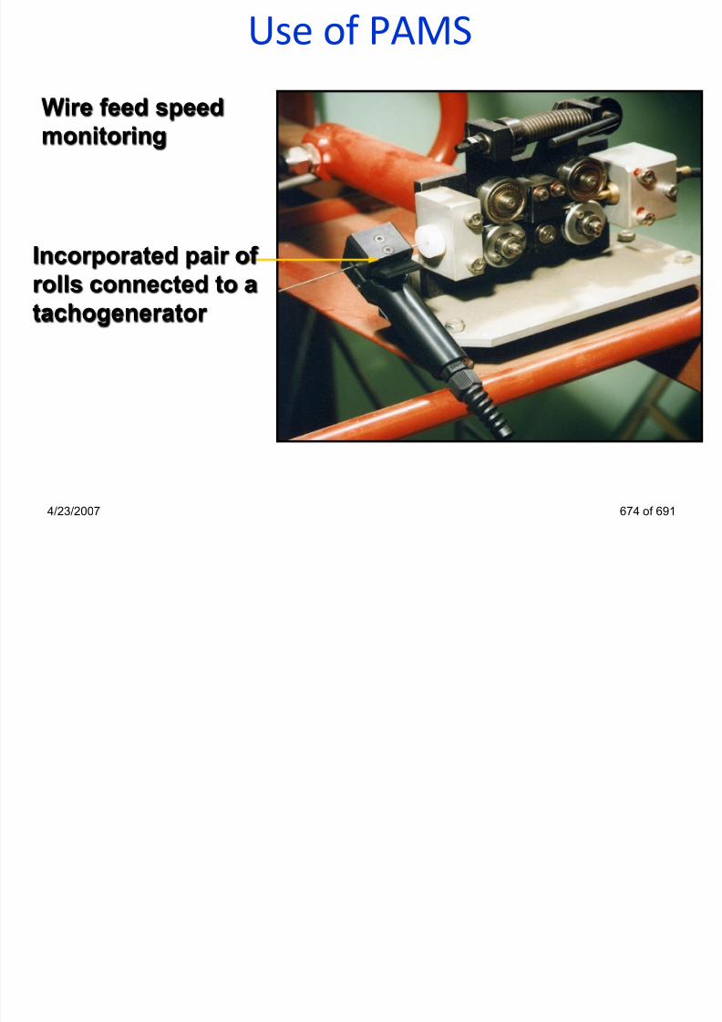
7/22/2019 weldinginspectioncswip-100402035204-phpapp02
http://slidepdf.com/reader/full/weldinginspectioncswip-100402035204-phpapp02 628/636
4/23/2007 674 of 691
Use of PAMS
Shielding gas flowrate monitoring
Heating element
sensor

7/22/2019 weldinginspectioncswip-100402035204-phpapp02
http://slidepdf.com/reader/full/weldinginspectioncswip-100402035204-phpapp02 629/636
4/23/2007 675 of 691
Summary• a welding power source can only be calibrated if it has
meters fitted
• the inspector should check for calibration stickers, datesetc.
• a welding power source without meters can only bevalidated that the control knobs provide repeatability
• the main role is to carryout “in process monitoring” toensure that the welding requirements are met during

7/22/2019 weldinginspectioncswip-100402035204-phpapp02
http://slidepdf.com/reader/full/weldinginspectioncswip-100402035204-phpapp02 630/636
ensure that the welding requirements are met duringproduction
4/23/2007 676 of 691
Welding Inspector
Macro/Micro Examination
Section 25

7/22/2019 weldinginspectioncswip-100402035204-phpapp02
http://slidepdf.com/reader/full/weldinginspectioncswip-100402035204-phpapp02 631/636
4/23/2007 677 of 691
Macro Preparat ion
Purpose
To examine the weld cross-section to give assurance that: -
• The weld has been made in accordance with the WPS
• The weld is free from defects
Specimen Preparation
• Full thickness slice taken from the weld (typical ly ~10mm thick)
• Width of slice sufficient to show all the weld and HAZ on both sides
plus some unaffected base material
• One face ground to a progressively fine finish (grit s izes 120 to ~ 400)
• Prepared face heavily etched to show all weld runs & all HAZ
• Prepared face examined at up to x10 (& usually photographed for records)

7/22/2019 weldinginspectioncswip-100402035204-phpapp02
http://slidepdf.com/reader/full/weldinginspectioncswip-100402035204-phpapp02 632/636
4/23/2007 678 of 691
• Prepared face may also be used for a hardness survey
Micro Preparat ion
PurposeTo examine a particular region of the weld or HAZ in order to:-
• To examine the microstructure
• Identify the nature of a crack or other imperfection
Specimen Preparation• A small piece is cut from the region of interest
(typical ly up to ~ 20mm x 20mm)
• The piece is mounted in plastic mould and the surface of interest
prepared by progressive grinding (to grit size 600 or 800)
• Surface polished on diamond impregnated cloths to a mirror finish
• Prepared face may be examined in as-polished condition & then lightly
etched

7/22/2019 weldinginspectioncswip-100402035204-phpapp02
http://slidepdf.com/reader/full/weldinginspectioncswip-100402035204-phpapp02 633/636
4/23/2007 679 of 691
• Prepared face examined under the microscope at up to ~ x 600
Macro / Micro ExaminationObject:
• Macro / microscopic examinations are used to give a visual
evaluation of a cross-section of a welded joint
• Carried out on full thickness specimens
• The width of the specimen should include HAZ, weld and
parent plate
• They maybe cut from a stop/start area on a weldersapproval test

7/22/2019 weldinginspectioncswip-100402035204-phpapp02
http://slidepdf.com/reader/full/weldinginspectioncswip-100402035204-phpapp02 634/636
4/23/2007 680 of 691
Macro / Micro ExaminationWill Reveal:
• Weld soundness
• Distribution of inclusions
• Number of weld passes
• Metallurgical structure of weld, fusion zone and HAZ
• Location and depth of penetration of weld
• Fillet weld leg and throat dimensions

7/22/2019 weldinginspectioncswip-100402035204-phpapp02
http://slidepdf.com/reader/full/weldinginspectioncswip-100402035204-phpapp02 635/636
4/23/2007 681 of 691
• Visual examination fordefects
• Cut transverse from the
weld
• Ground & polished P400grit paper
• Acid etch using 5-10%
nitric acid solution
• Wash and dry
• Visual evaluation under 5x
magnification
• Visual examination for
defects & grain structure
• Cut transverse from a
weld
• Ground & polished P1200grit paper, 1µm paste
• Acid etch using 1-5%
nitric acid solution
• Wash and dry
• Visual evaluation under
100-1000x magnification
Macro Micro

7/22/2019 weldinginspectioncswip-100402035204-phpapp02
http://slidepdf.com/reader/full/weldinginspectioncswip-100402035204-phpapp02 636/636
4/23/2007 682 of 691
• Report on results • Report on results
Metallographic Examination