Embed Size (px)
Citation preview
WELDING OF FERRITIC AND MARTENSITIC 11-14%Cr STEELS
This document is dedicated to the memory of
Dr Trevor Gooch,
friend and colleague,
who, as Chairman of Sub-Commission IX-H throughout the early 1990's, initiated
the work and provided much constructive comment and positive support.


Page 1
WELDING OF FERRITIC AND MARTENSITIC 11-14%Cr STEELS
BY
A W MARSHALL AND J C M FARRARMetrode Products Limited, UK
1. INTRODUCTION
The commercial history of stainless steel began with Brearly’s air-hardening ‘cutlery’ steel, a directancestor of the fully martensitic 0.2%C-12%Cr alloy now commonly known as type 420. Since the late1970s, this alloy has been rediscovered and has rapidly displaced carbon steel (plus corrosion inhibitors)for downhole tubulars in oilfield applications. There are good reasons for the renewed interest in thisgroup of materials since martensitic stainless steels can provide strength-to-weight ratio equal to highstrength low alloy steels and better than duplex stainless steels, combined with useful corrosion resistancefor many applications and at a relatively low cost.
The emergence of life cycle costs analysis as a formal discipline and improved steelmaking and workingtechnologies has given stainless ferritic and martensitic steels new status, but more importantly hasprovoked a fresh appraisal of the economics and performance potential of “lean alloyed” stainless steel ingeneral. The consequence of this vigorous activity has been evident in a wave of new or improved alloysbased on the 10.5-14%Cr system, the leanest being the utility ferritics, having the minimum chromiumlevel required to provide a stable passive film and the essential “stainlessness” of the alloy. As a whole,the microstructure of these alloys (loosely described 12% or 13%Cr) ranges from predominantly ferriticto fully martensitic, with the former having good resistance to stress corrosion cracking whilst the latterhave the highest strength.
Effective and widespread application of any alloy is dependent upon good weldability and this factoralone has previously restricted the exploitation of ferritic and martensitic stainless steels more than anyother (alloy 420, for example, is one of the few stainless steels with virtually no practical arc weldinghistory). However, advanced steel-making technology now enables tight control of composition and canprovide extremely low levels of carbon (and nitrogen) with consequent improvement in as-welded HAZproperties, as well as the reduction of chromium carbides which degrade corrosion performance.
These opportunities have not only helped to improve the weldability of utility ferritics, but have also beenfully exploited in the new ‘weldable supermartensitics’, in which corrosion performance and mechanicalproperties are greatly enhanced with additional alloying. Development of optimised and economicwelding procedures for supermartensitics is currently a challenging area of activity.
2. SCOPE
This review will attempt to establish the state-of-the-art as it exists at the turn of the millennium,particularly with respect to the welding and weldability of the wide range of mostly wrought 13%Crsteels and variants used primarily for combinations of ambient temperature strength and corrosionresistance. The evolution of the modern supermartensitics is still taking place and in May 1999 the firstmajor international conference devoted to the topic took place, the results of which have beenincorporated.
This review will not deal with the related but specialised steels listed below, some of which extend tohigher levels of chromium where appropriate. References are given to the principal reviews for eachgroup, although relatively few concentrate on welding:
- ‘Superferritics’ which typically exceed 20%Cr + Mo [1, 2, 3]
- Scaling-resistant ferritics based on 12%Cr or more with Si or Al additions – ‘Fecralloys’ and‘Sicromals’
Page 2
- Creep-resistant martensitics based on 11-12%Cr + Mo with strong carbide formers [4, 5]
- Precipitation hardening stainless martensitics [6] and higher alloy ‘controlled transformation’martensitics which require refrigeration as an essential step during heat treatment [6, 7]
With the exception of purely ferritic types, a number of alloys within the scope of this review are alsoavailable as castings. In most instances, these are welded in the same way as their wrought equivalentsexcept that consumables of dissimilar type are generally unsuitable if postweld solution treatment is to beapplied.
Applicable processes are the common arc welding processes: SMAW, GTAW, GMAW, FCAW, SAWand, for some materials, possibly PAW. The most appropriate of these will depend on a variety of factors,including availability of suitable consumables.
3. THE 13CR STEELS
For the purposes of this document, the 13%Cr steels have been divided into four sub-groups which aredescribed as follows:
Utility Ferritics Section 5/Table 1
Lean Martensitics Section 6/Table 2
Soft Martensitics Section 7/Table 3
New Supermartensitics Section 8/Table 4A-C
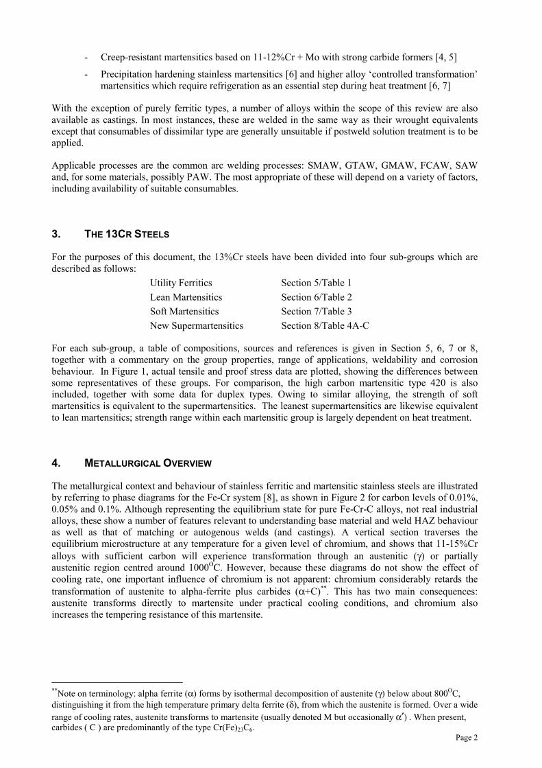
For each sub-group, a table of compositions, sources and references is given in Section 5, 6, 7 or 8,together with a commentary on the group properties, range of applications, weldability and corrosionbehaviour. In Figure 1, actual tensile and proof stress data are plotted, showing the differences betweensome representatives of these groups. For comparison, the high carbon martensitic type 420 is alsoincluded, together with some data for duplex types. Owing to similar alloying, the strength of softmartensitics is equivalent to the supermartensitics. The leanest supermartensitics are likewise equivalentto lean martensitics; strength range within each martensitic group is largely dependent on heat treatment.
4. METALLURGICAL OVERVIEW
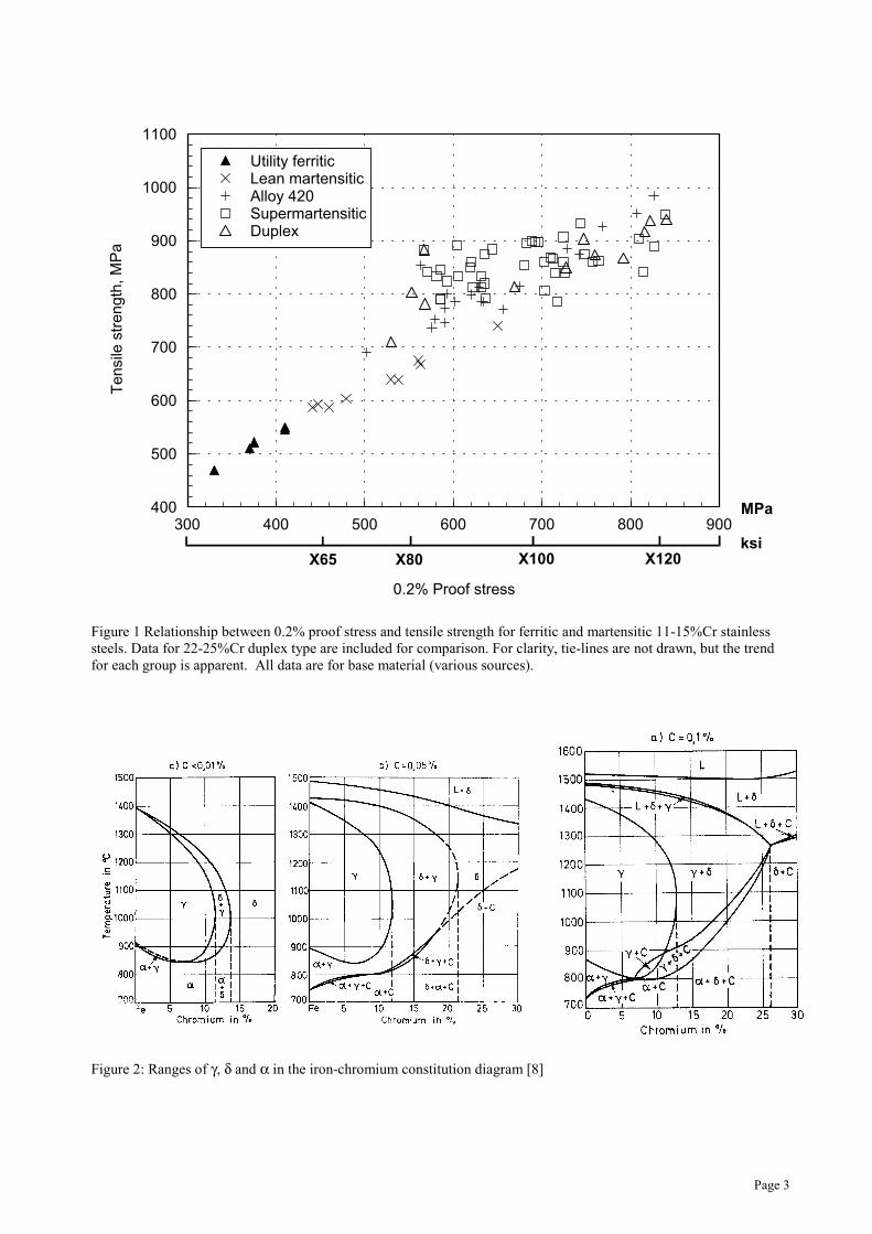
The metallurgical context and behaviour of stainless ferritic and martensitic stainless steels are illustratedby referring to phase diagrams for the Fe-Cr system [8], as shown in Figure 2 for carbon levels of 0.01%,0.05% and 0.1%. Although representing the equilibrium state for pure Fe-Cr-C alloys, not real industrialalloys, these show a number of features relevant to understanding base material and weld HAZ behaviouras well as that of matching or autogenous welds (and castings). A vertical section traverses theequilibrium microstructure at any temperature for a given level of chromium, and shows that 11-15%Cralloys with sufficient carbon will experience transformation through an austenitic (γ) or partiallyaustenitic region centred around 1000OC. However, because these diagrams do not show the effect ofcooling rate, one important influence of chromium is not apparent: chromium considerably retards thetransformation of austenite to alpha-ferrite plus carbides (α+C)**. This has two main consequences:austenite transforms directly to martensite under practical cooling conditions, and chromium alsoincreases the tempering resistance of this martensite.
**Note on terminology: alpha ferrite (α) forms by isothermal decomposition of austenite (γ) below about 800OC,distinguishing it from the high temperature primary delta ferrite (δ), from which the austenite is formed. Over a widerange of cooling rates, austenite transforms to martensite (usually denoted M but occasionally α′) . When present,carbides ( C ) are predominantly of the type Cr(Fe)23C6.
Page 3
300 400 500 600 700 800 900
0.2% Proof stress
400
500
600
700
800
900
1000
1100T
en
sile
str
en
gth
, M
Pa
Utility ferriticLean martensiticAlloy 420SupermartensiticDuplex
X65 X80 X100 X120ksi
MPa
Figure 1 Relationship between 0.2% proof stress and tensile strength for ferritic and martensitic 11-15%Cr stainlesssteels. Data for 22-25%Cr duplex type are included for comparison. For clarity, tie-lines are not drawn, but the trendfor each group is apparent. All data are for base material (various sources).
Figure 2: Ranges of γ, δ and α in the iron-chromium constitution diagram [8]
Page 4
4.1 Solidification
Delta ferrite is always the primary solidification phase. The dendrite cores initially inherit carbon-depleted pure FeCr which is the first to solidify at the dendrite tips. Carbon concentrated in the last-solidifying liquid diffuses rapidly into the growing dendrites, although this homogenization may beincomplete in weld metals. Only when carbon exceeds about 0.08% is some austenite also formed at theterminal stage of solidification (the region marked L+δ+γ in figure 2c for 0.1%C alloys). In this case, theexcess carbon rejected at the primary ferrite dendrites forces the interdendritic liquid to solidify ascarbon-enriched austenite.
Recent and detailed solidification studies [9] on low carbon highly alloyed weld metals (martensitic 12-15%Cr with ~10% other) have shown that interdendritic partitioning of the additional solute elements(e.g. Ni, Mo, Nb, Si, Cu) occurs at the fully ferritic solidification front, but soon afterwards thismicrosegregation is largely eliminated by rapid diffusion. However, earlier authors [4, 10], evidentlyreferring to high carbon and leaner alloys, claim that segregation can persist to the extent that a finallymartensitic microstructure may retain ferrite originating from both carbon-depleted dendrite cores andinterdendritic locations enriched with the ferrite formers Mo, Si, etc. Moreover, the highest alloy weldmetals of supermartensitic type are balanced to avoid segregation caused by final austenitic solidification[11] which will occur if compositions reach the Fe-Cr-Ni peritectic range (F + FA solidification mode).The literature reveals few clear reports of hot cracking in these alloys, and although there can be no doubtthat a form of solidification cracking can occur, it must be concluded that this hazard is far less likely thanin, for example, austenitic stainless steel welds. Highly restrained fillet welds with a concave profile werefound to be sensitive to centreline cracking [12] which was eliminated by the use of a fully martensitic13%Cr-4%Ni type consumable. The exact mechanism has not been established, but cracking is believedto occur in the temperature range 900-1350OC where shrinkage strains cause fracture of ferrite grains oraustenite-ferrite grain boundaries. It is notable that hot cracking was confined to martensitic welds withhigher chromium equivalent (see Section 4.2.1), in which retained ferrite was present at roomtemperature.
4.2 Transformations
During further cooling, the most important feature is the influence of chromium on transformation toaustenite, without which the alloy cannot be fully hardened by cooling or quenching to martensite. Theaustenite region (Figure 2) is bounded by a ‘gamma loop’ which narrows rapidly and closes just withinthe range of 12%Cr alloys. This austenite region is surrounded by a duplex region of austenite and ferrite(γ+δ). Increasing carbon (and nitrogen) contents widen and extend the duplex region to considerablyhigher Cr levels, with a relatively smaller expansion of the gamma loop [8, 13].
Alloys cooling through or quenched from the austenitic or duplex region will vary in martensite (orferrite) with proximity to the austenitic region, and furthermore, as already indicated, any residualmicrosegregation inherited from solidification will alter the course of local transformations in a weldfusion zone, compared with a HAZ of the same composition.
Not surprisingly, the sensitivity of transformation behaviour to relatively small differences in compositionfurther complicates the prediction and control of HAZ and especially matching weld metalmicrostructures. To exploit these transformations with minimal additional alloying in order to realise thefull economic potential of the leanest 12%Cr alloys is also a significant challenge in composition controlfor the steelmaker.
Additions are very limited for alloys to be processed easily to a predominantly ferritic condition, whilemaintaining satisfactory HAZ behaviour. In martensitic alloys there is considerably more scope foralloying, but again this must be limited to maintain practical transformation boundaries for processing andwelding. Although carbon is the cheapest and most potent element for controlling transformation, it mustalso be restricted for optimum weldability and toughness.
Page 5
4.2.1. Transformation control in 12%Cr ferritics
The early ferritic steels (types 405, 409, 410S) often have compositions placing them outside the gammaloop or at the edge of the duplex region and they may remain essentially ferritic under all coolingconditions. The absence of any transformation leads to rapid and irreversible grain growth in the hightemperature HAZ, drastically raising its impact transition temperature and reducing local ductility.Conversely, in simple martensitics (type 410) the hardened HAZ can be improved by tempering to restorereasonable toughness and ductility.
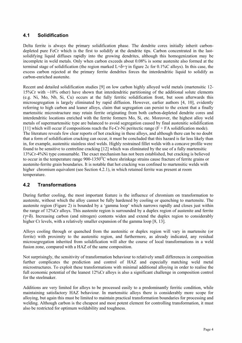
To improve HAZ microstructure control in these and related lean alloys, chromium must be restricted,while in the newer alloys two specific adjustments are applied: carbon is reduced (or almost eliminated bymodern steelmaking techniques) and nickel is substituted to promote austenite. Nickel has distinctadvantages over carbon: it expands the austenite range (gamma loop) very effectively, but withoutnoticeably increasing the as-quenched hardness of martensite. It is now recognised that a low carbon lath-type martensitic HAZ with less than about 10-20% ferrite offers far better properties than a mixed ferritic-martensitic microstructure [14, 15, 16]. Examples of low carbon lath-type martensitic and mixed ferritic-martensitic HAZ microstructures are shown in Fig. 3. This is achieved in the more recent utility ferritics,with the help of some nickel to obtain the critical balance of composition. The steel itself also gains morestrength, ductility and toughness by inheriting grain-refined ferrite due to processing through the austeniterange.
Figure 3a) 0.01%C-11%Cr-1.5%Ni (FF = 2.74) Lath type martensite HAZ x 500
Figure 3b) 0.02%C-12%Cr-0.5%Ni (FF = 8.42) Mixed ferritic-martensitic HAZ x 500
Predictive equations or diagrams are most convenient for evaluating the behaviour of a givenmulticomponent alloy or for optimising composition. Two frequently used formulae are the Kaltenhauserferrite factor [17] and chromium equivalent [18]. These are similar except for some coefficient values,particularly Al, and the number of elements (which are expressed as %):
Ferrite factor, FF = Cr+6Si+8Ti+4Mo+2Al+4Nb-2Mn-4Ni-40(C+N)
Chromium equivalent, Creq = Cr+6Si+8Ti+4Mo+12Al+5Nb+1.5W+11V-2Mn-4Ni-2Co-Cu-40C-30N
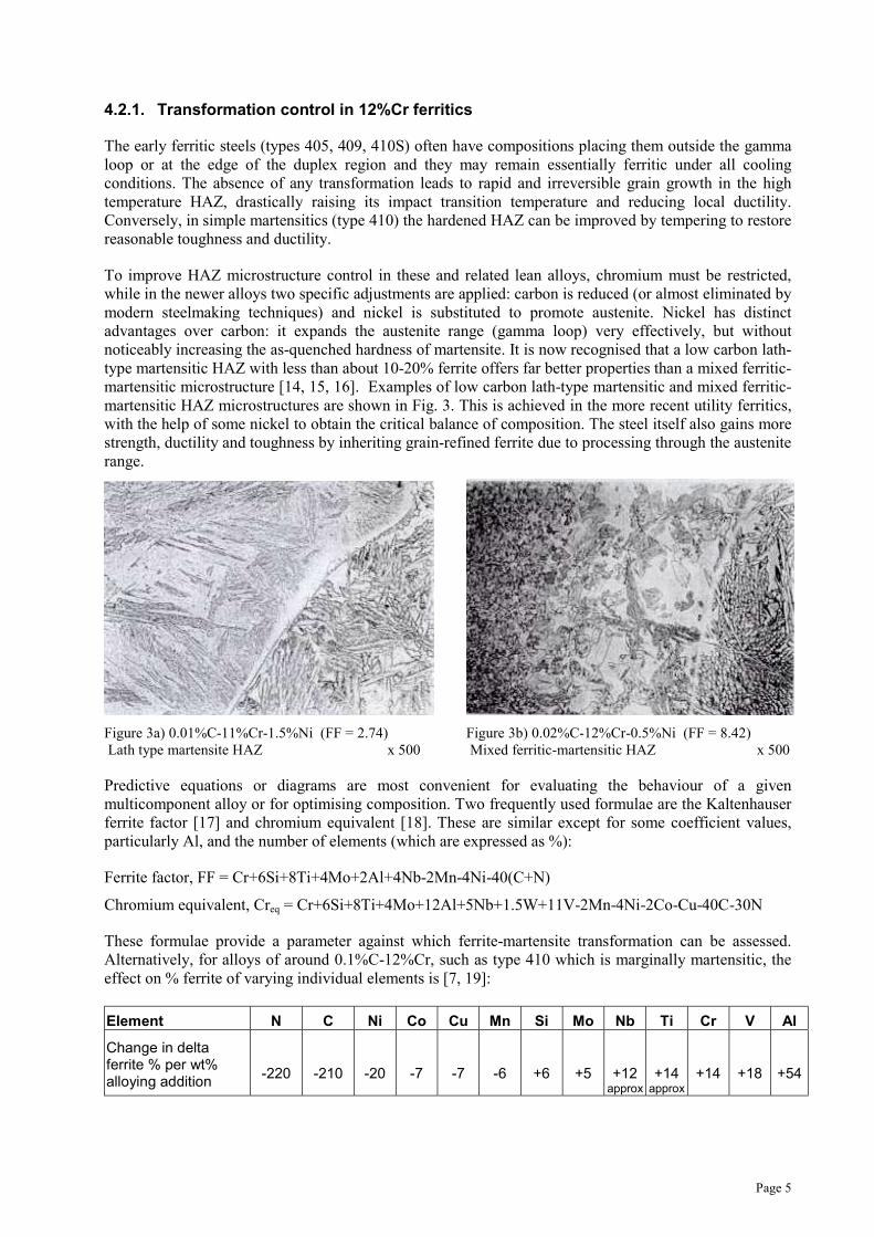
These formulae provide a parameter against which ferrite-martensite transformation can be assessed.Alternatively, for alloys of around 0.1%C-12%Cr, such as type 410 which is marginally martensitic, theeffect on % ferrite of varying individual elements is [7, 19]:
Element N C Ni Co Cu Mn Si Mo Nb Ti Cr V Al
Change in deltaferrite % per wt%alloying addition
-220 -210 -20 -7 -7 -6 +6 +5 +12approx
+14approx
+14 +18 +54
Page 6
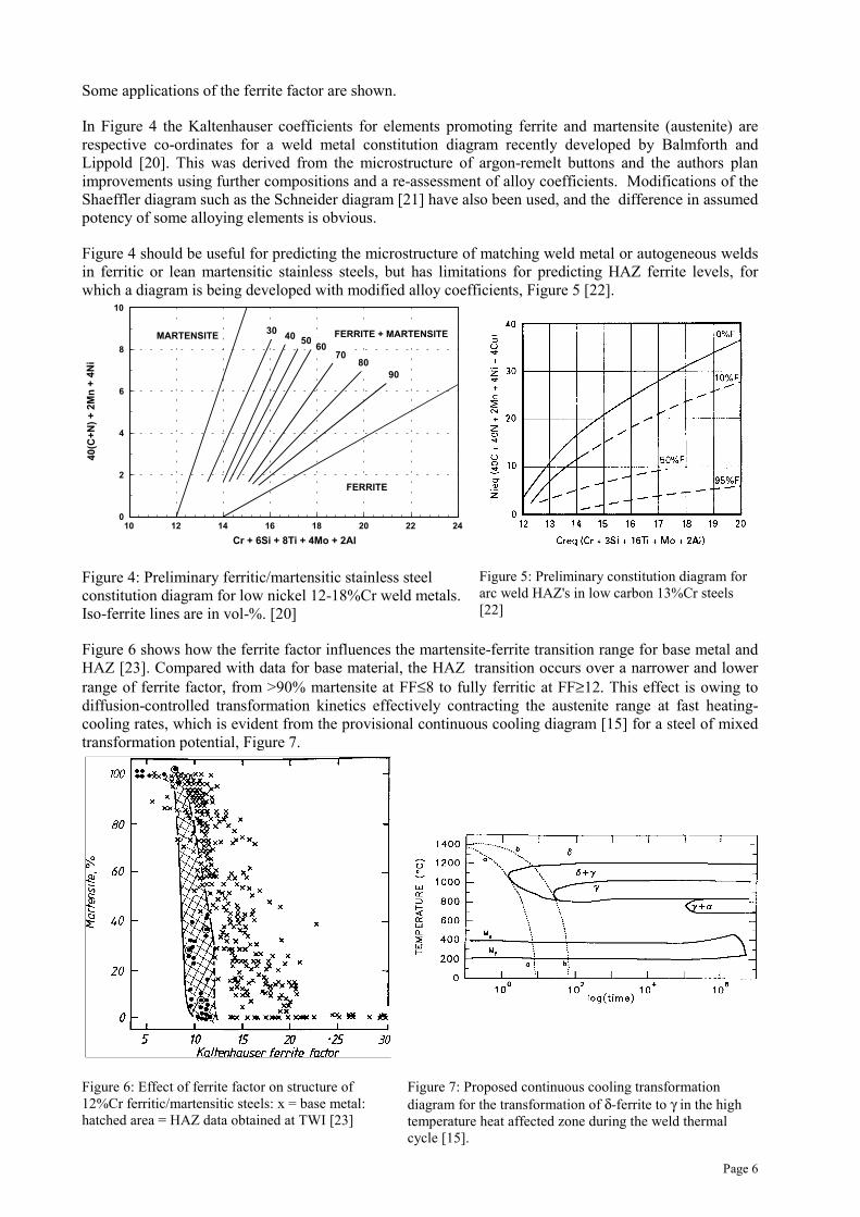
Some applications of the ferrite factor are shown.
In Figure 4 the Kaltenhauser coefficients for elements promoting ferrite and martensite (austenite) arerespective co-ordinates for a weld metal constitution diagram recently developed by Balmforth andLippold [20]. This was derived from the microstructure of argon-remelt buttons and the authors planimprovements using further compositions and a re-assessment of alloy coefficients. Modifications of theShaeffler diagram such as the Schneider diagram [21] have also been used, and the difference in assumedpotency of some alloying elements is obvious.
Figure 4 should be useful for predicting the microstructure of matching weld metal or autogeneous weldsin ferritic or lean martensitic stainless steels, but has limitations for predicting HAZ ferrite levels, forwhich a diagram is being developed with modified alloy coefficients, Figure 5 [22].
10 12 14 16 18 20 22 24
Cr + 6Si + 8Ti + 4Mo + 2Al
0
2
4
6
8
10
40(C
+N
) +
2M
n +
4N
i
MARTENSITE FERRITE + MARTENSITE
FERRITE
4030
9080
70
5060
Figure 4: Preliminary ferritic/martensitic stainless steelconstitution diagram for low nickel 12-18%Cr weld metals.Iso-ferrite lines are in vol-%. [20]
Figure 5: Preliminary constitution diagram forarc weld HAZ's in low carbon 13%Cr steels[22]
Figure 6 shows how the ferrite factor influences the martensite-ferrite transition range for base metal andHAZ [23]. Compared with data for base material, the HAZ transition occurs over a narrower and lowerrange of ferrite factor, from >90% martensite at FF≤8 to fully ferritic at FF≥12. This effect is owing todiffusion-controlled transformation kinetics effectively contracting the austenite range at fast heating-cooling rates, which is evident from the provisional continuous cooling diagram [15] for a steel of mixedtransformation potential, Figure 7.
Figure 6: Effect of ferrite factor on structure of12%Cr ferritic/martensitic steels: x = base metal:hatched area = HAZ data obtained at TWI [23]
Figure 7: Proposed continuous cooling transformationdiagram for the transformation of δ-ferrite to γ in the hightemperature heat affected zone during the weld thermalcycle [15].
Page 7
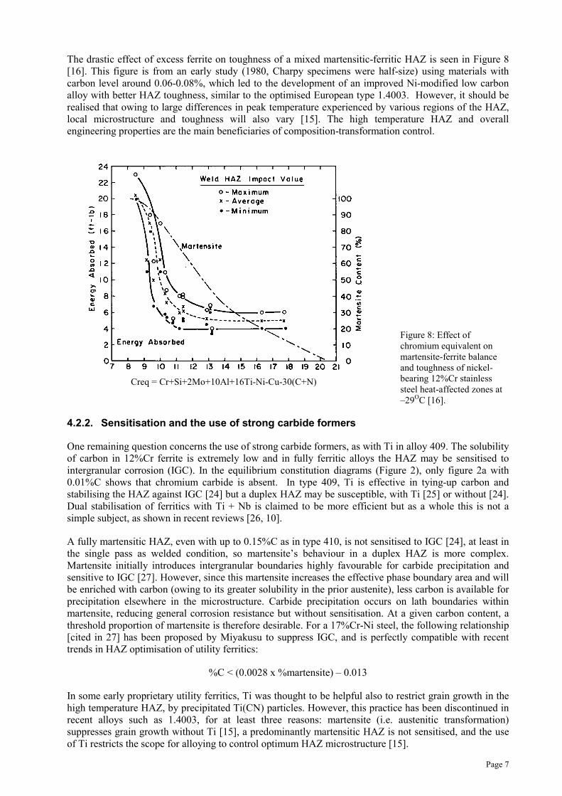
The drastic effect of excess ferrite on toughness of a mixed martensitic-ferritic HAZ is seen in Figure 8[16]. This figure is from an early study (1980, Charpy specimens were half-size) using materials withcarbon level around 0.06-0.08%, which led to the development of an improved Ni-modified low carbonalloy with better HAZ toughness, similar to the optimised European type 1.4003. However, it should berealised that owing to large differences in peak temperature experienced by various regions of the HAZ,local microstructure and toughness will also vary [15]. The high temperature HAZ and overallengineering properties are the main beneficiaries of composition-transformation control.
Figure 8: Effect ofchromium equivalent onmartensite-ferrite balanceand toughness of nickel-bearing 12%Cr stainlesssteel heat-affected zones at–29OC [16].
4.2.2. Sensitisation and the use of strong carbide formers
One remaining question concerns the use of strong carbide formers, as with Ti in alloy 409. The solubilityof carbon in 12%Cr ferrite is extremely low and in fully ferritic alloys the HAZ may be sensitised tointergranular corrosion (IGC). In the equilibrium constitution diagrams (Figure 2), only figure 2a with0.01%C shows that chromium carbide is absent. In type 409, Ti is effective in tying-up carbon andstabilising the HAZ against IGC [24] but a duplex HAZ may be susceptible, with Ti [25] or without [24].Dual stabilisation of ferritics with Ti + Nb is claimed to be more efficient but as a whole this is not asimple subject, as shown in recent reviews [26, 10].
A fully martensitic HAZ, even with up to 0.15%C as in type 410, is not sensitised to IGC [24], at least inthe single pass as welded condition, so martensite’s behaviour in a duplex HAZ is more complex.Martensite initially introduces intergranular boundaries highly favourable for carbide precipitation andsensitive to IGC [27]. However, since this martensite increases the effective phase boundary area and willbe enriched with carbon (owing to its greater solubility in the prior austenite), less carbon is available forprecipitation elsewhere in the microstructure. Carbide precipitation occurs on lath boundaries withinmartensite, reducing general corrosion resistance but without sensitisation. At a given carbon content, athreshold proportion of martensite is therefore desirable. For a 17%Cr-Ni steel, the following relationship[cited in 27] has been proposed by Miyakusu to suppress IGC, and is perfectly compatible with recenttrends in HAZ optimisation of utility ferritics:
%C < (0.0028 x %martensite) – 0.013
In some early proprietary utility ferritics, Ti was thought to be helpful also to restrict grain growth in thehigh temperature HAZ, by precipitated Ti(CN) particles. However, this practice has been discontinued inrecent alloys such as 1.4003, for at least three reasons: martensite (i.e. austenitic transformation)suppresses grain growth without Ti [15], a predominantly martensitic HAZ is not sensitised, and the useof Ti restricts the scope for alloying to control optimum HAZ microstructure [15].
Creq = Cr+Si+2Mo+10Al+16Ti-Ni-Cu-30(C+N)
4.2.3. Additional alloying in 12%Cr martensitics
The 12%Cr ‘soft’ martensitics were first developed as cast alloys in the late 1950’s [8] based on theprinciple of obtaining the essential austenite-martensite transformation by using at least 3%Ni to replaceabout 0.1% carbon of earlier alloys. The resultant low carbon (<0.05%C) ‘soft’ lath-type martensite offersan exceptional combination of excellent toughness with high strength and good ductility.
Like the new generation of utility ferritics, they were also developed with the objective of improving bothweldability and properties in comparison with previous alloys of their type. In addition, the unique abilityof increased nickel to extend good toughness to lower temperatures (unlike carbon) is a particular bonusfor the soft martensitics, and this is exploited in alloys with nickel raised to about 6%. Most specificationsfor soft martensitics include up to 1%Mo, mainly to suppress a tendency to carbide embrittlement whenfurnace cooling after tempering [28]. This addition also helps to improve corrosion performance.
The new supermartensitics are effectively wrought or forged soft martensitics with further improvementsobtained by limiting carbon to around 0.015% or less, and raising corrosion performance with moremolybdenum, and also copper in some cases. Up to at least 6%Ni is usually needed to ensure a ferrite-freemicrostructure. The as-transformed HAZ hardness of these new alloys is close to the theoretical limit forpure carbon-free martensite and, unlike conventional soft martensitics, it is intended that satisfactoryservice performance can be obtained in weldments without tempering by PWHT.
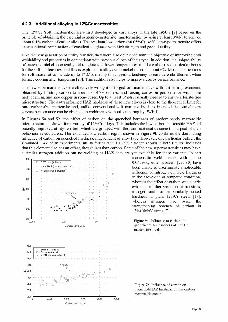
In Figures 9a and 9b, the effect of carbon on the quenched hardness of predominantly martensiticmicrostructure is shown for a variety of 12%Cr alloys. This includes the low carbon martensitic HAZ ofrecently improved utility ferritics, which are grouped with the lean martensitics since this aspect of theirbehaviour is equivalent. The expanded low carbon region shown in Figure 9b confirms the dominatinginfluence of carbon on quenched hardness, independent of alloy type. However, one particular outlier, thesimulated HAZ of an experimental utility ferritic with 0.078% nitrogen shown in both figures, indicatesthat this element also has an effect, though less than carbon. Some of the new supermartensitics may havea similar nitrogen addition but no welding or HAZ data are yet available for these variants. In soft
Page 8
martensitic weld metals with up to0.045%N, other workers [29, 30] havebeen unable to discriminate a noticeableinfluence of nitrogen on weld hardnessin the as-welded or tempered condition,whereas the effect of carbon was clearlyevident. In other work on martensitics,nitrogen and carbon similarly raisedhardness in plain 12%Cr steels [19],whereas nitrogen had twice thestrengthening potency of carbon in12%CrMoV steels [7].
0.001 0.01 0.1
Carbon content, %
200
300
400
500
600
700
800
HV
CCT data (Atkins)
Weld/HAZ (Various sources)
410NiMo weld (Gooch)
0 0.01 0.02 0.03 0.04 0.05
Carbon content, %
200
250
300
350
400
450
500
550
600
HV
Lean martensiticSuper martensitic410NiMo weld (Gooch)
Influence of carbon on quenched/HAZ hardness of 12%Cr martensitic steels
Influence of carbon on quenched/HAZ hardness of low carbon softmartensitic steels
0.078%N
0.078%N
Figure 9a: Influence of carbon onquenched/HAZ hardness of 12%Crmartensitic steels
Figure 9b: Influence of carbon onquenched/HAZ hardness of low carbonmartensitic steels
Page 9
4.2.4. Transformation control in low-carbon martensitics
The soft martensitics are air-hardening: cooling rate has almost no influence on the finally transformedmartensite, except for small variations in residual austenite and delta ferrite [8]. This well-controlledtransformation behaviour confers reliable engineering properties to both base material and matchingwelds (after heat treatment) in contrast to some of the leaner alloys already described.
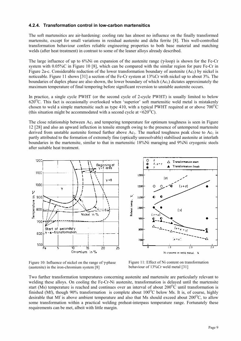
The large influence of up to 6%Ni on expansion of the austenite range (γ-loop) is shown for the Fe-Crsystem with 0.05%C in Figure 10 [8], which can be compared with the similar region for pure Fe-Cr inFigure 2a-c. Considerable reduction of the lower transformation boundary of austenite (Ac3) by nickel isnoticeable. Figure 11 shows [31] a section of the Fe-Cr system at 13%Cr with nickel up to about 3%. Theboundaries of duplex phase are also shown, the lower boundary of which (Ac1) dictates approximately themaximum temperature of final tempering before significant reversion to unstable austenite occurs.
In practice, a single cycle PWHT (or the second cycle of 2-cycle PWHT) is usually limited to below620OC. This fact is occasionally overlooked when ‘superior’ soft martensitic weld metal is mistakenlychosen to weld a simple martensitic such as type 410, with a typical PWHT required at or above 700OC(this situation might be accommodated with a second cycle at <620OC).
The close relationship between Ac1 and tempering temperature for optimum toughness is seen in Figure12 [28] and also an upward inflection in tensile strength owing to the presence of untempered martensitederived from unstable austenite formed further above Ac1. The marked toughness peak close to Ac1 ispartly attributed to the formation of extremely fine (optically unresolvable) stabilised austenite at interlathboundaries in the martensite, similar to that in martensitic 18%Ni maraging and 9%Ni cryogenic steelsafter suitable heat treatment.
Figure 10: Influence of nickel on the range of γ-phase(austenite) in the iron-chromium system [8]
Figure 11: Effect of Ni content on transformationbehaviour of 13%Cr weld metal [31]
Two further transformation temperatures concerning austenite and martensite are particularly relevant towelding these alloys. On cooling the Fe-Cr-Ni austenite, transformation is delayed until the martensitestart (Ms) temperature is reached and continues over an interval of about 200OC until transformation isfinished (Mf), though 90% transformation is complete about 100OC below Ms. It is, of course, highlydesirable that Mf is above ambient temperature and also that Ms should exceed about 200OC, to allowsome transformation within a practical welding preheat-interpass temperature range. Fortunately theserequirements can be met, albeit with little margin.
Page 10
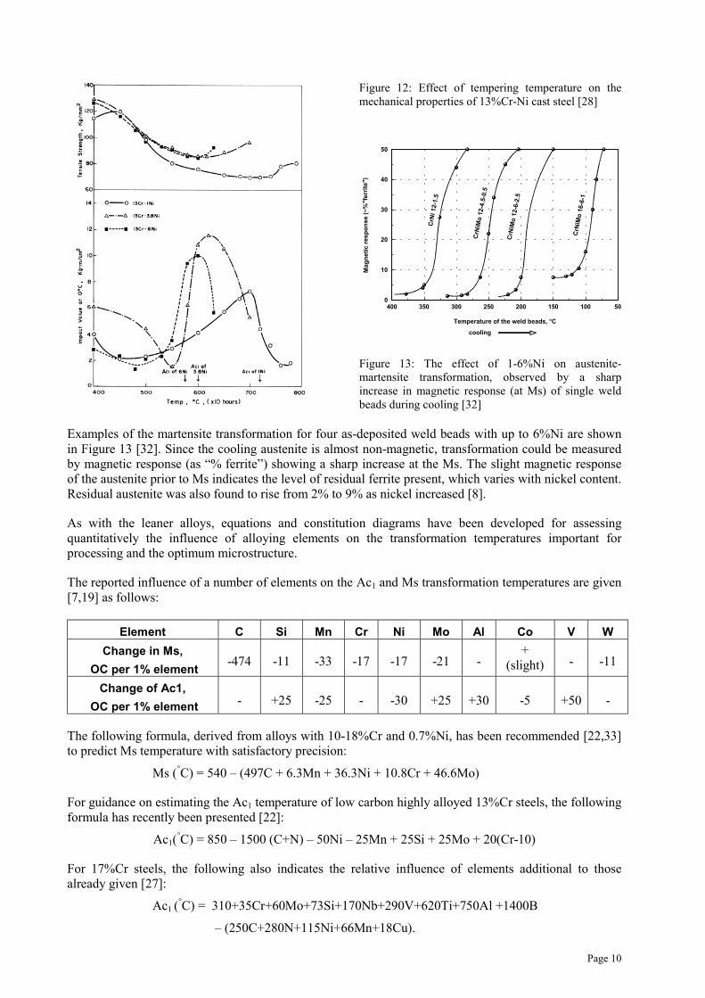
Figure 12: Effect of tempering temperature on themechanical properties of 13%Cr-Ni cast steel [28]
50100150200250300350400
Temperature of the weld beads, °C
0
10
20
30
40
50
Mag
net
ic r
esp
on
se (
~%
"fer
rite
")
CrN
i 12-
1.5
CrN
iMo
12-
4.5-
0.5
CrN
iMo
12-
6-2.
5
CrN
iMo
16-
6-1
cooling
Figure 13: The effect of 1-6%Ni on austenite-martensite transformation, observed by a sharpincrease in magnetic response (at Ms) of single weldbeads during cooling [32]
Examples of the martensite transformation for four as-deposited weld beads with up to 6%Ni are shownin Figure 13 [32]. Since the cooling austenite is almost non-magnetic, transformation could be measuredby magnetic response (as “% ferrite”) showing a sharp increase at the Ms. The slight magnetic responseof the austenite prior to Ms indicates the level of residual ferrite present, which varies with nickel content.Residual austenite was also found to rise from 2% to 9% as nickel increased [8].
As with the leaner alloys, equations and constitution diagrams have been developed for assessingquantitatively the influence of alloying elements on the transformation temperatures important forprocessing and the optimum microstructure.
The reported influence of a number of elements on the Ac1 and Ms transformation temperatures are given[7,19] as follows:
Element C Si Mn Cr Ni Mo Al Co V W
Change in Ms,
OC per 1% element-474 -11 -33 -17 -17 -21 -
+(slight) - -11
Change of Ac1,
OC per 1% element - +25 -25 - -30 +25 +30 -5 +50 -
The following formula, derived from alloys with 10-18%Cr and 0.7%Ni, has been recommended [22,33]to predict Ms temperature with satisfactory precision:
Ms (°C) = 540 – (497C + 6.3Mn + 36.3Ni + 10.8Cr + 46.6Mo)
For guidance on estimating the Ac1 temperature of low carbon highly alloyed 13%Cr steels, the followingformula has recently been presented [22]:
Ac1(°C) = 850 – 1500 (C+N) – 50Ni – 25Mn + 25Si + 25Mo + 20(Cr-10)
For 17%Cr steels, the following also indicates the relative influence of elements additional to thosealready given [27]:
Ac1 (°C) = 310+35Cr+60Mo+73Si+170Nb+290V+620Ti+750Al +1400B
– (250C+280N+115Ni+66Mn+18Cu).
Page 11
Owing to the slower diffusion and transformation kinetics around Ac1, and the competitive influence ofmany elements, its effective temperature is not so well defined as the Ms, which is essentially adiffusionless transformation. As a generalisation, Ac1 temperature is lowered by elements known to beaustenite formers, and raised by ferrite formers, whereas Ms temperature is lowered by the total alloyinglevel. However, owing to local inhomogeneities, the residual transformations around Mf also become lesspredictable.
The transformed microstructure of these alloys can also be assessed on a constitution diagram such as theSchaeffler or a modified Schaeffler diagram. The higher level of alloying probably makes this approachmore reliable than methods based on the ferrite factor determined on much leaner alloys. Figure 13 showsan expanded portion of the Schaeffler diagram including the location of some relevant alloys [8].
0 2 4 6 8 10 12 14 16 18 20 22
Creq = Cr + Mo + 1.5Si + 0.5Nb
0
2
4
6
8
10
12
14
Nie
q =
Ni
+ 3
0C
+ 0
.5M
n
M
A + M
M+F
A
FM+F
10%
12Cr/6Ni
A+F
20%
40%
80%
AISI410
Cr~12.5%
AISI410
Cr~12.5%
Weld metal
12Cr/4Ni
16/6
14/5/1
16/5/1
17/4
17/4/1
A+M+F
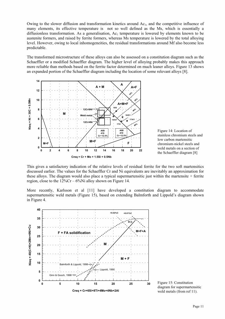
Figure 14: Location ofstainless chromium steels andlow carbon martensiticchromium-nickel steels andweld metals on a section ofthe Schaeffler diagram [8]
This gives a satisfactory indication of the relative levels of residual ferrite for the two soft martensiticsdiscussed earlier. The values for the Schaeffler Cr and Ni equivalents are inevitably an approximation forthese alloys. The diagram would also place a typical supermartensitic just within the martensite + ferriteregion, close to the 12%Cr – 6%Ni alloy shown on Figure 14.
More recently, Karlsson et al [11] have developed a constitution diagram to accommodatesupermartensitic weld metals (Figure 15), based on extending Balmforth and Lippold’s diagram shownin Figure 4.
0 5 10 15 20 25 30
Creq = Cr+6Si+8Ti+4Mo+4Nb+2Al
0
5
10
15
20
25
30
35
40
Nie
q =
40
(C+
N)+
2M
n+
4N
i+C
u
F + FA solidification
M+A
M+F+A
M
M + F
>0.02%C <0.01%C
Ginn & Gooch, 1998
Balmforth & Lippold, 1998
Lippold, 1990
Figure 15: Constitutiondiagram for supermartensiticweld metals (from ref 11).
Page 12
5. UTILITY FERRITICS
Table 1: Plain 11-12%Cr – low C < 0.03% - little additional alloying
Typical composition, weight %GRADE/
TRADENAME C Mn Si Cr Ni N Others
Manufacturer
405 0.025 <1 0.5 12 - - Al 0.2 Generic
409 0.025 <1 0.5 11 - - Ti 0.2 Generic
410S <0.08 0.5 0.3 12 <0.5 - - Generic.API 5LC52-1200 pipe
3CR12 0.025 1.2 0.5 11.5 0.5 0.02 - Columbus steel [34]
Nirosta 4003 0.02 1.1 0.5 11 0.4 - - Krupp [35]
CR13LC 0.03 1.5 <0.3 13 0.2 <0.03 Nb 0.035 Mannesmann. Pipe (25%ferrite). [36, 37]
LC-12Cr 0.03 0.8 0.4 12 0.4 - - Kawasaki
Polarit 850 0.02 1.1 0.4 11 0.8 <0.02 Outukumpu Polarit Oy
[14, 38, 39, 40]
5.1 Microstructure
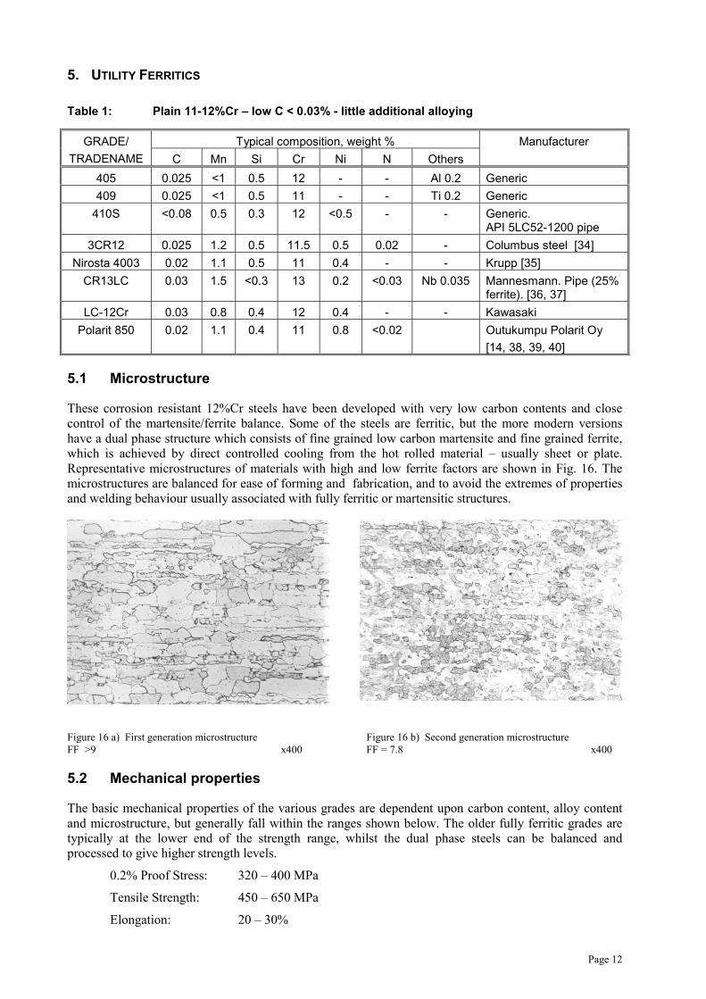
These corrosion resistant 12%Cr steels have been developed with very low carbon contents and closecontrol of the martensite/ferrite balance. Some of the steels are ferritic, but the more modern versionshave a dual phase structure which consists of fine grained low carbon martensite and fine grained ferrite,which is achieved by direct controlled cooling from the hot rolled material – usually sheet or plate.Representative microstructures of materials with high and low ferrite factors are shown in Fig. 16. Themicrostructures are balanced for ease of forming and fabrication, and to avoid the extremes of propertiesand welding behaviour usually associated with fully ferritic or martensitic structures.
Figure 16 a) First generation microstructure Figure 16 b) Second generation microstructureFF >9 x400 FF = 7.8 x400
5.2 Mechanical properties
The basic mechanical properties of the various grades are dependent upon carbon content, alloy contentand microstructure, but generally fall within the ranges shown below. The older fully ferritic grades aretypically at the lower end of the strength range, whilst the dual phase steels can be balanced andprocessed to give higher strength levels.
0.2% Proof Stress: 320 – 400 MPa
Tensile Strength: 450 – 650 MPa
Elongation: 20 – 30%
Page 13
Toughness: Impact values of parent steels are typically in excess of 100J at +20°C withsome grades giving values as high as 200J. Ductile/brittle transitiontemperatures are typically in the range -20°C to -40°C and most grades givepoor lower shelf values at temperatures below -50°C. In this respect thesesteels are not intended for low temperature or cryogenic service.
The best combination of mechanical properties is achieved with thinner materials. Loss of tensileproperties (~10%) can be expected above 6mm and loss of toughness above 12 – 15mm thickness.
5.2.1 Elevated temperature properties
Although not primarily designed as high temperature materials, this group of steels offers usefulproperties up to moderate temperature. The maximum service temperatures range from 450°C forcontinuous temperature/loaded structures up to about 750°C for intermittent temperature/unloadedstructures. The 12%Cr content provides good scaling and oxidation resistance as well as usefulperformance in sulphur-bearing and hot industrial gases/fumes. In addition, the newer steels do not showsignificant "475°C" embrittlement in the range 370-510°C. Experience with the older steels is alsosatisfactory, although high Cr+Ti have been implicated in the brittle failure of a deviant ferritic steel with13.4%Cr-0.5%Ti [Creamer, 1980].
5.3 Product forms
The modern dual phase types are produced as cold rolled strip and sheet up to 3mm and hot rolled coiland plate up to about 25mm in thickness. Other manufactured forms include seamless pipes and tubes,cold formed sections, perforated plate and expanded metal. The older, plain ferritic types are usuallyrestricted to 6 mm in thickness.
5.4 Applications
Sugar refining plant; hoppers, chutes and silos in the metal and minerals handling and processingindustries; vehicle/rail car bodies/chassis; fertiliser and refuse slurry handling plant; high temperatureexhaust ducts and flues.
In general terms the steels provide properties which bridge the gap between coated/painted/galvanisedsteels and the more expensive standard austenitic stainless steels. Although much softer than low alloyQ+T steels, they may be more cost-effective in applications requiring wet abrasion resistance.
5.5 Welding and weldability
These steels are routinely welded without preheat using most of the common arc welding processes andaustenitic stainless steel consumables. These provide adequately strong and tough weld metal, minimisethe risk of HAZ hydrogen cracking and are sufficiently highly alloyed to cope with dilution of the parentsteel(s).
5.5.1 Welding consumables
The readily available type 309L consumables are most commonly used, and are considered to providesuperior tolerance to dilution with base material, compared with types 308, 308L and 316L. Dilutionleading to a ‘triplex’ austenitic-ferritic-martensitic weld metal microstructure may give poor ductility andtoughness [41]. Type 309L consumables are also suitable for dissimilar welds between utility ferritics andmost other grades of C/Mn and stainless steels. For applications such as hot exhaust ducting operating upto 600°C weld metals with better thermal stability are preferable, such as type 309 with controlled ferriteand ~0.06%C or one of the leaner nickel-base filler metals which offer a better match of thermalexpansion, albeit at higher cost.
Welds are rarely subjected to PWHT, but when specified (possibly with the intention of improvingfatigue life) this should be at around 620°C for a limited period and its effect on the weld metal must beconsidered – Ni base weld metal may be an option. For type 409 steels used in automotive exhaust
Page 14
systems, matching composition gas shielded metal cored or self shielded flux cored and similar 409Nbsolid gas shielded welding wires are used.
5.5.2 HAZ properties
Because of the use of non-matching weld metals, the overall properties of weldments in utility ferriticshave until recently been dominated by the HAZ, particularly ductility and toughness. A low carbon,martensitic HAZ with minimal ferrite is now considered optimum and the compositional factorscontrolling this are determined by steelmaking and grade limitations. The modern proprietary grades arenow balanced to offer improved HAZ properties. However, the older grades, e.g. types 405, 409 and410S, are likely to have HAZs with poor toughness and may not be fracture-safe except in thin sections.Even with the modern grades, most manufacturers’ literature considers it prudent to limit welding heatinput and interpass temperature and so restrict grain growth in the HAZ. Typical suggested limits are1kJ/mm heat input and 100°C maximum interpass temperature and, if strictly adhered to, these wouldseverely limit the use of higher productivity welding processes such as the flux cored and submerged arcprocesses. In real terms significant improvements in ferritic HAZ toughness arising from limiting grainsize can only be achieved at heat inputs as low as 0.1 – 0.2kJ/mm [42].
Studies on actual and simulated HAZs generally show ductile/brittle transition temperatures (DBTT)above 0°C and for this reason it is generally recognised that these steels should not be used for criticalwelded fabrications which are pressure containing or similarly loaded.
However, toughness of the HAZ is critically dependent upon whether it consists of grain coarsened ferriteor low carbon tempered martensite. The latter is much tougher and is the basis of the claim made bycertain producers that their steels give enhanced HAZ properties [40, 35]. There is, however, a finedividing line between the two microstructures and very careful control of composition is required toachieve the optimum properties (Fig. 7). For this reason it is possible to obtain significantly differentproperties from different casts of nominally the same grade of steel [16].
5.6 Structural integrity
In spite of the HAZ toughness limitations, these steels have been used in a wide range of weldedfabrications with few, if any, reported instances of brittle fracture. The reasons for this are:
a) The potential loss of toughness is well recognised and the most commonly usedthicknesses are below 10mm and often below 6mm, which results in an effectivereduction of the DBTT.
b) Normal welded joints seldom have weld fusion lines which result in a through thicknessplanar HAZ, so any crack initiating in the embrittled HAZ is likely to be arrested in eithertough parent steel or austenitic weld metal.
Many practical fabrication guidance notes recommend that planar HAZs are avoided,either by modification of the weld preparation, or by ensuring good penetration ofindividual weld beads to give an irregular fusion line/HAZ.
c) With the correct choice of consumable, the risk of either hydrogen or solidificationcracking (which could be an initiating defect) is low. However, precautions should betaken to avoid the risk of fatigue cracking in service.
Although these steels tend not to be used in pressure containing structures, they are often exploited inother safety critical structures, particularly road and rail vehicles. For these structural applications, specialtests have been developed which are designed to test models or actual welded components undersimulated accident conditions. They examine load absorption and deformation as well as the failuremechanism [43].
Page 15
5.7 Corrosion resistance
These steels with 11 to 13%Cr are just “stainless” but are not designed to compete directly with 300series austenitic, duplex or higher alloyed stainless steels in more aggressive media. Even underatmospheric conditions, particularly marine, urban and industrial, they will exhibit some staining anddiscolouration, and are therefore not suitable for external decorative or industrial applications. Thedispersed martensite often present in the more recently developed types may also be susceptible topreferential attack in some test media [41].
5.7.1 Pitting corrosion
The utility ferritics are not designed for use in pitting environments and, to avoid pitting in an aqueousenvironment at room temperature, the chloride content should not exceed 200 ppm [44]. ThePREN
***values are very low at ~12 when compared with type 316L stainless (PREN ~24) and 22%Crduplex stainless steels (PREN 33 -35).
5.7.2 Sour service
Somewhat surprisingly, type 405 stainless is listed in NACE MR 0175-95 as being acceptable for directexposure to sour environments provided the steel and, presumably, the weld/HAZ do not exceed 22HRCmaximum hardness.
5.7.3 Intergranular corrosion
The sensitivity of the utility ferritics to HAZ intergranular corrosion depends critically upon themicrostructure of the HAZ [24]. Type 409 with a ferritic HAZ plus titanium stabilisation, and type 410with a fully martensitic HAZ, were not sensitised, whereas type 405 with a duplex martensite-ferritemicrostructure was found to be sensitive to intergranular corrosion – albeit in media that are lessaggressive than those used in the recommended practices for austenitic stainless steels.
5.7.4 Corrosion/abrasion
Under dry abrasion conditions (moisture up to 4%) utility ferritics offer no advantage over mild steels. Athigher moisture levels they are greatly superior to all non or low alloyed steels and comparable to 304Land 316L types.
A further benefit lies in so-called “slideability”, the ease with which materials, powders, minerals, etc.,move in chutes, silos and hoppers. In this respect they show advantages over all plain mild, coated andgalvanised steels and even some 300 type stainless steels and aluminium alloys [44].
5.7.5 High temperature corrosion (see also 5.2.1)
The utility ferritics offer scaling resistance in dry air up to about 800°C but will suffer severe corrosion iftemperatures fall below the dew point and acids form from combustion products. Under such conditionsthey offer little benefit over mild steel.
*** Pitting resistance equivalent number, PREN = Cr + 3.3Mo + 16N

Page 16
6. LEAN MARTENSITICS
Table 2: Plain 11-13%Cr steels with various C contents, low nickel
Typical composition, weight %GRADE/TRADENAME C Mn Si Cr Ni Mo Cu N Others
ManufacturerNotes
410 <0.15 0.5 0.3 12 <0.5 - - - - DIN X10Cr13.CA15 (cast)
414 <0.15 <1 0.5 12.5 1.8 - - - - -
420 0.2 0.5 0.3 13 0.2 - - - - API 5CT L-80(tube)
‘KCR-13A’ <0.08 <1 <0.5 12 <1 <0.6 - - -Kubota.Centricast tube[45]
CR13LC(+Ni)
0.02 1.5 0.2 13 1.5 <0.1 0.5 <0.03 -[37, 36]Mannesman(<1% ferrite)Pipe
‘12Cr-mod’ 0.01 1.5 0.2 11 0.8 - 0.5 <0.02 -[46, 47, 48]Kawasaki. Pipe
6.1 Microstructure
These steels contain 11-13% chromium with minimal additional alloying. The older standard grades 410,420, etc., have carbon contents in the range 0.1 to 0.2%, are air hardening and give a predominantlymartensitic microstructure. The steels are invariably heat treated before use, and all grades containtempered martensite with varying levels of chromium carbide and residual ferrite. The more modernlower carbon grades have small alloying additions and are ”tuned” to avoid the presence of ferrite and sominimise HAZ grain coarsening during welding. These represent an evolutionary step towards the new‘lean supermartensitic’ steels (see Table 4-1).
6.2 Mechanical properties
6.2.1 Room temperature
The mechanical properties of the various grades vary depending upon product form, carbon content andheat treatment, but can be divided into two sub-groups:
i) Higher carbon grades (type 410/420)
0.2% Proof Stress: 500 – 1000 MPa
Tensile Strength: 700 – 1400 MPa
Elongation: 15 – 30%
Toughness: Impact values are modest and generally less than 50J at roomtemperature: the highest carbon grades (up to 0.3%) can be heattreated to give proof stresses in excess of 1100 MPa, but withcorrespondingly low ductility and toughness. At the higheststrength levels these are reduced to virtually zero, and suchgrades have very limited applications.
Page 17
ii) Lower carbon grades (KCR-13A, etc.)
0.2% Proof Stress: 400 – 700 MPa
Tensile Strength: 600 – 800 MPa
Elongation: 20 – 35%
Toughness: These lower C steels with modest alloying derive their propertiesfrom tempered low carbon martensite and achieve goodcombinations of strength and toughness, e.g. 150-250J at +20OC.They also exhibit useful sub-zero values at -40OC but retain littleuseful toughness below -75OC.
6.2.2 Elevated temperatures
Type 410/420 alloys retain reasonable high temperature properties and at 600OC exhibit about 45% of theroom temperature strength. For use at temperatures up to 500OC, the steels are tempered at 600OC and anysubsequent service embrittlement in the critical 350-500OC range is minimal. Note, however, that thesealloys are reported to be susceptible to phosphorus-dependent reversible temper embrittlement [49].
The lower carbon steels are not specifically designed for elevated temperature use, but may findapplication for flowlines containing hot oil at temperatures in the range 100-200OC. These grades showminimal loss of proof stress up to about 400OC, followed by a fairly steep decline. As with all 12%Cr leanmartensitic steels, there is evidence of some loss of ductility in the 350-500OC range.
6.3 Product forms
Castings, forgings and plate.
Seamless, centricast and welded tubes (lower carbon grades).
6.4 Applications
Most applications are designed to exploit one or more of the following features:
ii) basic stainlessness (12%Cr)
iii) modest cost
iv) high strength
v) elevated temperature properties.
They include: hydrocrackers, reactor vessels, distillation plant and associated pipework in oil refineries:
furnace parts, linings and run out rolls in the steel industry:
cast steam valve bodies, pumps, shafts, turbine parts and burner nozzles where modestcorrosion resistance or high temperature properties are required.
downhole tubulars; with the lower carbon grades also being promoted for flow lines andlinepipe in the oil and gas industry.
6.5 Welding and weldability
6.5.1 Higher carbon versions (C >0.1%)
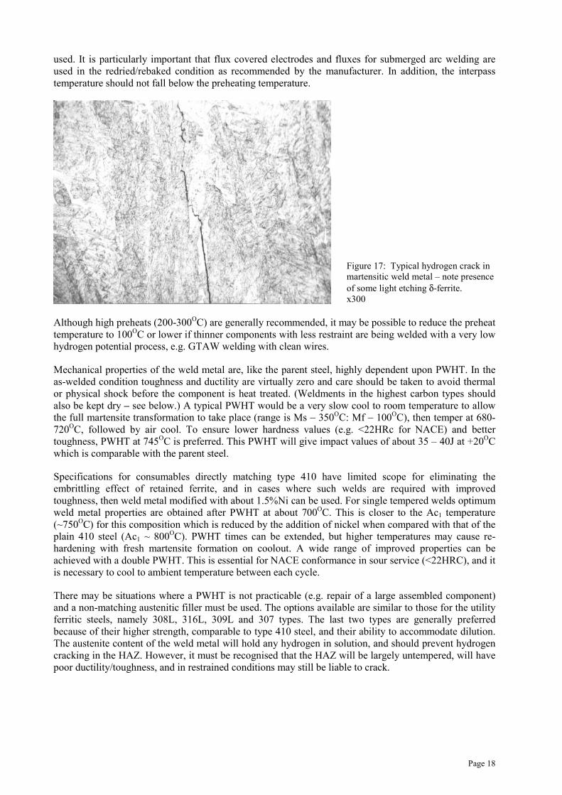
These steels (typified by type 410, with 0.08-0.15%C) are usually welded with “matching” 12%Crconsumables, particularly where similar mechanical properties are required of the weld. In such cases, thecompleted weldment must be subject to PWHT to achieve reasonable toughness and ductility in both theHAZ and weld metal. Until PWHT there is a risk of hydrogen induced cracking in the HAZ or the weldmetal or both and an example of weld metal hydrogen cracking is shown in Figure 17. To avoid hydrogencracking, preheats of between 200OC and 300OC and low hydrogen consumables/processes should be
Page 18
used. It is particularly important that flux covered electrodes and fluxes for submerged arc welding areused in the redried/rebaked condition as recommended by the manufacturer. In addition, the interpasstemperature should not fall below the preheating temperature.
Figure 17: Typical hydrogen crack inmartensitic weld metal – note presenceof some light etching δ-ferrite.x300
Although high preheats (200-300OC) are generally recommended, it may be possible to reduce the preheattemperature to 100OC or lower if thinner components with less restraint are being welded with a very lowhydrogen potential process, e.g. GTAW welding with clean wires.
Mechanical properties of the weld metal are, like the parent steel, highly dependent upon PWHT. In theas-welded condition toughness and ductility are virtually zero and care should be taken to avoid thermalor physical shock before the component is heat treated. (Weldments in the highest carbon types shouldalso be kept dry – see below.) A typical PWHT would be a very slow cool to room temperature to allowthe full martensite transformation to take place (range is Ms – 350OC: Mf – 100OC), then temper at 680-720OC, followed by air cool. To ensure lower hardness values (e.g. <22HRc for NACE) and bettertoughness, PWHT at 745OC is preferred. This PWHT will give impact values of about 35 – 40J at +20OCwhich is comparable with the parent steel.
Specifications for consumables directly matching type 410 have limited scope for eliminating theembrittling effect of retained ferrite, and in cases where such welds are required with improvedtoughness, then weld metal modified with about 1.5%Ni can be used. For single tempered welds optimumweld metal properties are obtained after PWHT at about 700OC. This is closer to the Ac1 temperature(~750OC) for this composition which is reduced by the addition of nickel when compared with that of theplain 410 steel (Ac1 ~ 800OC). PWHT times can be extended, but higher temperatures may cause re-hardening with fresh martensite formation on coolout. A wide range of improved properties can beachieved with a double PWHT. This is essential for NACE conformance in sour service (<22HRC), and itis necessary to cool to ambient temperature between each cycle.
There may be situations where a PWHT is not practicable (e.g. repair of a large assembled component)and a non-matching austenitic filler must be used. The options available are similar to those for the utilityferritic steels, namely 308L, 316L, 309L and 307 types. The last two types are generally preferredbecause of their higher strength, comparable to type 410 steel, and their ability to accommodate dilution.The austenite content of the weld metal will hold any hydrogen in solution, and should prevent hydrogencracking in the HAZ. However, it must be recognised that the HAZ will be largely untempered, will havepoor ductility/toughness, and in restrained conditions may still be liable to crack.