Embed Size (px)
Citation preview
The INL is a U.S. Department of Energy National Laboratory operated by Battelle Energy Alliance
INL/EXT-07-12289
Weld Tests Conducted
by the Idaho National
Laboratory
Larry R. Zirker
Lance Laurhass
James A. Dowalo
February 2007

INL/EXT-07-12289
Weld Tests Conducted by the Idaho National Laboratory
Larry R. Zirker
Lance Lauerhass
James A. Dowalo
February 2007
Idaho Falls, Idaho 83415 Aiken, South Carolina
Prepared for the U.S. Department of Energy
Office of Global Nuclear Materials Threat Reduction (NA-212)
Under DOE Idaho Operations Office
Contract DE-AC07-05ID14517

Weld Tests Conducted by the INL INL/EXT-07-12289
Revision 0 - DRAFT February 2007
ii
This page intentionally left blank.

Weld Tests Conducted by the INL INL/EXT-07-12289
Revision 0 - DRAFT February 2007
iii
Executive Summary
During fiscal year 2006, the Idaho National Laboratory (INL) performed the several tests and other work to finalize the design for closure of Mobile Melt-Dilute (MMD) canisters.
Several minor changes were made to the shield plug design. The closure groove weld between the top of
the canister and the top plate of the shielding plug was reduced from 0.5-in deep to 0.375-in. The chamfer groove diameter was increased for the plug weld. A lifting pintle replaced a lifting lug. A
groove for a plug cap was machined into the top plate and a cap was designed to weld over the plug to
seal the canister. Drawings were revised to reflect these changes.
A quick disconnect valve had been designed to provide the capability to maintain the canister at deep
vacuum, once the fuel is dried. Testing performed during 2005 yielded unacceptable results, so the
project investigated the problem and re-tested with improved results. Upon analysis of the test, it was discovered that the test had been compromised because the fittings had been welded incorrectly.
To correct the test, quick disconnect test was divided into two parts: Threaded Seal Test and the Heated
Vacuum Test. The Threaded Seal Test duplicated the failed 2005 test. When tested, the internal seals of two sets of fittings were heated to 500° C, and held a 200 millitorr vacuum. Over two days of testing, two
fittings held vacuum and one failed. The failed fitting may have been attributed to a handling error by the
testers. When the decision is made to proceed with the MMD system, the project should procure and test
production-run valves to ensure performance of these precision devices.
An alterative to using the quick disconnect fitting was investigated. Three sizes of stainless steel tubing,
0.25-in, 0.375-in, and 0.5-in, all with 0.035-in wall thickness, were successfully pin or seal weld using commercially available resistance welding equipment from Centerline Special Machinery Division in
Windsor, Ontario, Canada. Also preliminary studies conducted at University of Windsor showed that
stainless steel tubing pin welds can be real-time inspected with ultrasonic inspection methods.
Three additional documents are included with this report: a closure welding machine specification, a
canister and assembly component specification and an Idaho National Laboratory Engineering Design
File report on the welding code justification of the welding changes made on the shield plug.

Weld Tests Conducted by the INL INL/EXT-07-12289
Revision 0 - DRAFT February 2007
iv
Contents
1. Introduction ................................................................................................................................... 1
2. Canister Disconnect Fitting Connection Port .................................................................................. 1
3. Weld Issues ................................................................................................................................. 12
4. Canister Connection Port Tube Welding ...................................................................................... 15
5. Closure Welding Machine Specification ...................................................................................... 20
6. Path Forward ............................................................................................................................... 22
Figures
Figure 1, Staubli socket (left) and plug (right) .......................................................................................... 1
Figure 2, FSUIn -0177-EC-02.................................................................................................................. 2
Figure 3, Drawing FSU-0188-EC Rev 0 .................................................................................................. 3
Figure 4, Drawing FSU-0190-EC Rev 0 .................................................................................................. 4
Figure 5, cleaning the mating surfaces and connecting the vacuum tubing to the socket fitting ................. 5
Figure 6, filing the glove with helium ...................................................................................................... 5
Figure 7, schematic of disconnect fitting test setup................................................................................... 7
Figure 8, Flange with ¼-in tube and welded plug with attached socket ..................................................... 7
Figure 9, puffing or flooding threaded fitting with helium during helium leak check testing ..................... 8
Figure 10, Chamber in furnace with vacuum and monitoring lines along with TC wires ........................... 8
Figure 11, Cleaning parts and tubing........................................................................................................ 9
Figure 12, Canister debris on a white sheet of paper ................................................................................. 9
Figure 13, Vee groove joint between flange and cap .............................................................................. 10
Figure 14, sketch of vee groove joint ..................................................................................................... 10
Figure 15, Pressure, pressure/temperature, temperature values of plug 2-265 heated-vacuum test data. ... 11
Figure 16, Test coupons with 0.5-in deep vee groove joint ..................................................................... 12
Figure 17, three test coupons with different chamfer sizes and depths .................................................... 13
Weld Tests Conducted by the INL INL/EXT-07-12289
Revision 0 - DRAFT February 2007
v
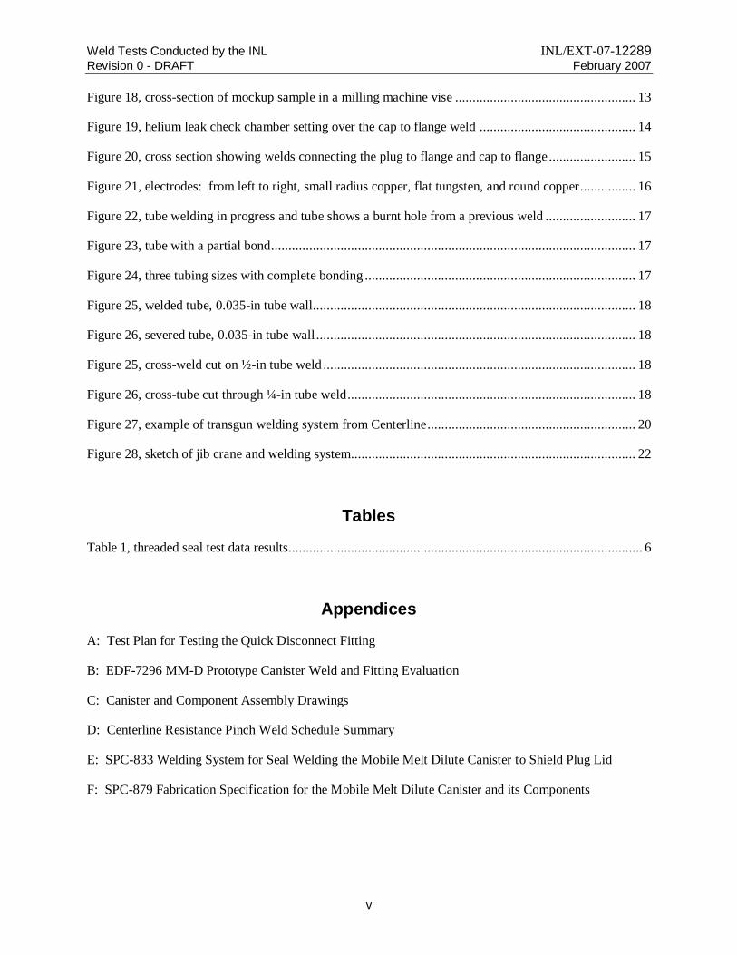
Figure 18, cross-section of mockup sample in a milling machine vise .................................................... 13
Figure 19, helium leak check chamber setting over the cap to flange weld ............................................. 14
Figure 20, cross section showing welds connecting the plug to flange and cap to flange ......................... 15
Figure 21, electrodes: from left to right, small radius copper, flat tungsten, and round copper................ 16
Figure 22, tube welding in progress and tube shows a burnt hole from a previous weld .......................... 17
Figure 23, tube with a partial bond ......................................................................................................... 17
Figure 24, three tubing sizes with complete bonding .............................................................................. 17
Figure 25, welded tube, 0.035-in tube wall............................................................................................. 18
Figure 26, severed tube, 0.035-in tube wall ............................................................................................ 18
Figure 25, cross-weld cut on ½-in tube weld .......................................................................................... 18
Figure 26, cross-tube cut through ¼-in tube weld ................................................................................... 18
Figure 27, example of transgun welding system from Centerline ............................................................ 20
Figure 28, sketch of jib crane and welding system.................................................................................. 22
Tables
Table 1, threaded seal test data results...................................................................................................... 6
Appendices
A: Test Plan for Testing the Quick Disconnect Fitting
B: EDF-7296 MM-D Prototype Canister Weld and Fitting Evaluation
C: Canister and Component Assembly Drawings
D: Centerline Resistance Pinch Weld Schedule Summary
E: SPC-833 Welding System for Seal Welding the Mobile Melt Dilute Canister to Shield Plug Lid
F: SPC-879 Fabrication Specification for the Mobile Melt Dilute Canister and its Components
Weld Tests Conducted by the INL INL/EXT-07-12289
Revision 0 - DRAFT February 2007
vi
Acronyms
AVC: arc voltage control
EDF: engineering design file
FSU: Former Soviet Union
INL: Idaho National Laboratory
MM-D: Mobile Melt-Dilute Project.
NNSA: National Nuclear Security Administration
RTC: Reactor Test Complex
TC: thermocouple
UT: ultrasonic testing

Weld Tests Conducted by the INL INL/EXT-07-12289
Revision 0 - DRAFT February 2007
1
Weld Tests Conducted by the Idaho National Laboratory
1. Introduction
During the fiscal year of 2006, the Idaho National Laboratory (INL) performed testing to develop
welds for Mobile Melt-Dilute (MMD) canister closure, including the lid weld, evacuation tubing closure
and the final cap weld. Associated testing was performed to validate the performance of the proposed quick-disconnect valve, and an alternative “pinch weld” approach was developed. This resistance weld
would provide a more positive seal, and could be less expensive than purchasing the precision quick
disconnect valves, depending upon the number of canisters to be processed.
2. Canister Disconnect Fitting Connection Port
Staubli Quick Disconnect Fitting. The current MMD canister port design uses a prototype quick disconnect fitting developed by Staubli Corporation. Staubli designed a prototype quick disconnect
fitting to hold a 200 millitorr vacuum at 500° C long enough until a cap is welded over the fitting and
onto the top plate of the shield plug. This quick disconnect fitting set consists of two parts: the plug and socket. Figure 1 shows both pieces of the Staubli quick disconnect fitting set. The plug fitting is welded
onto the top plate of the MMD canister shield plug, and interconnects with internal passages into the
MMD canister.
Figure 1, Staubli socket (left) and plug (right)
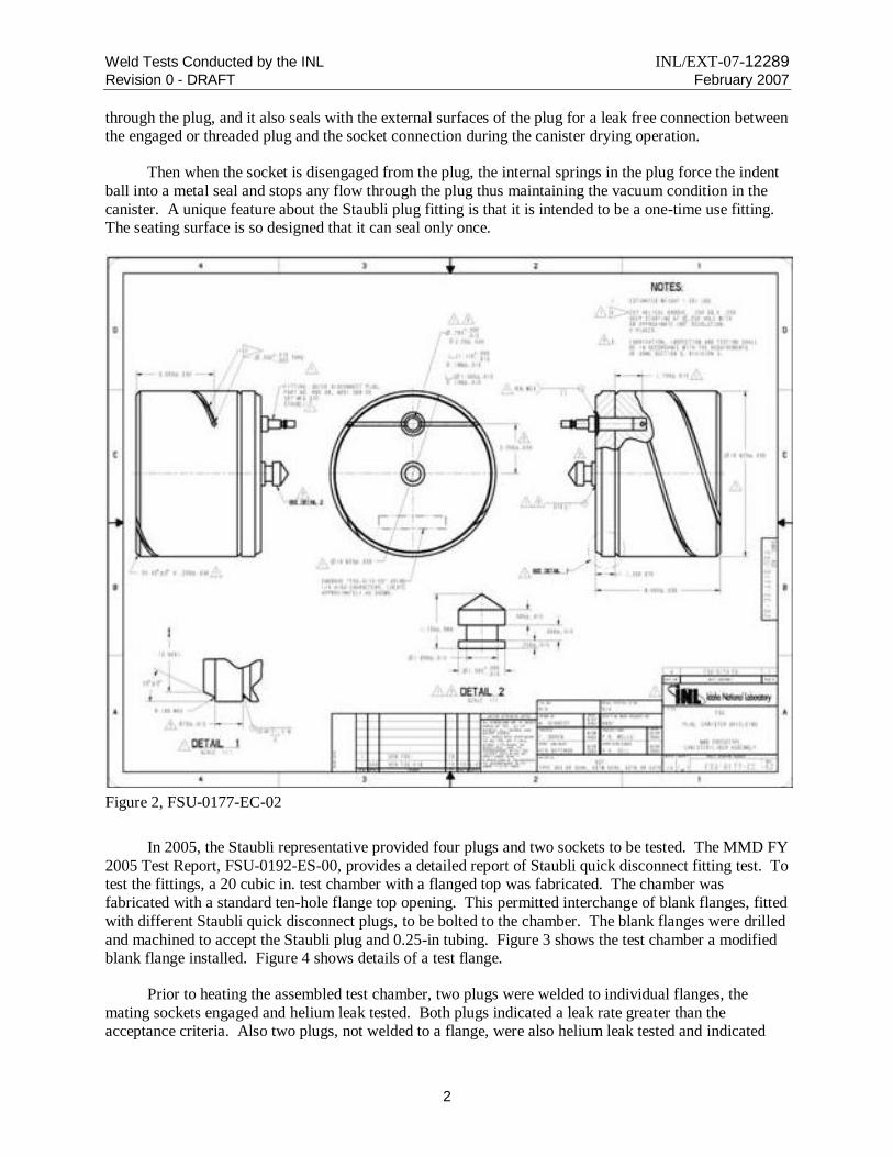
The welded joint and the interconnections are shown on Figure 2. After the socket fitting is
threaded onto the plug, the socket provides an external threaded connection point between the vacuum
system and the MMD canister. Both fittings provide a passage through which the external vacuum system evacuates the canister during the drying operation as the induction furnace heats the canister.
When the socket engages with the plug, it actuates or opens the internal indent ball to allow air flow
Weld Tests Conducted by the INL INL/EXT-07-12289
Revision 0 - DRAFT February 2007
2
through the plug, and it also seals with the external surfaces of the plug for a leak free connection between the engaged or threaded plug and the socket connection during the canister drying operation.
Then when the socket is disengaged from the plug, the internal springs in the plug force the indent
ball into a metal seal and stops any flow through the plug thus maintaining the vacuum condition in the
canister. A unique feature about the Staubli plug fitting is that it is intended to be a one-time use fitting. The seating surface is so designed that it can seal only once.
Figure 2, FSU-0177-EC-02
In 2005, the Staubli representative provided four plugs and two sockets to be tested. The MMD FY
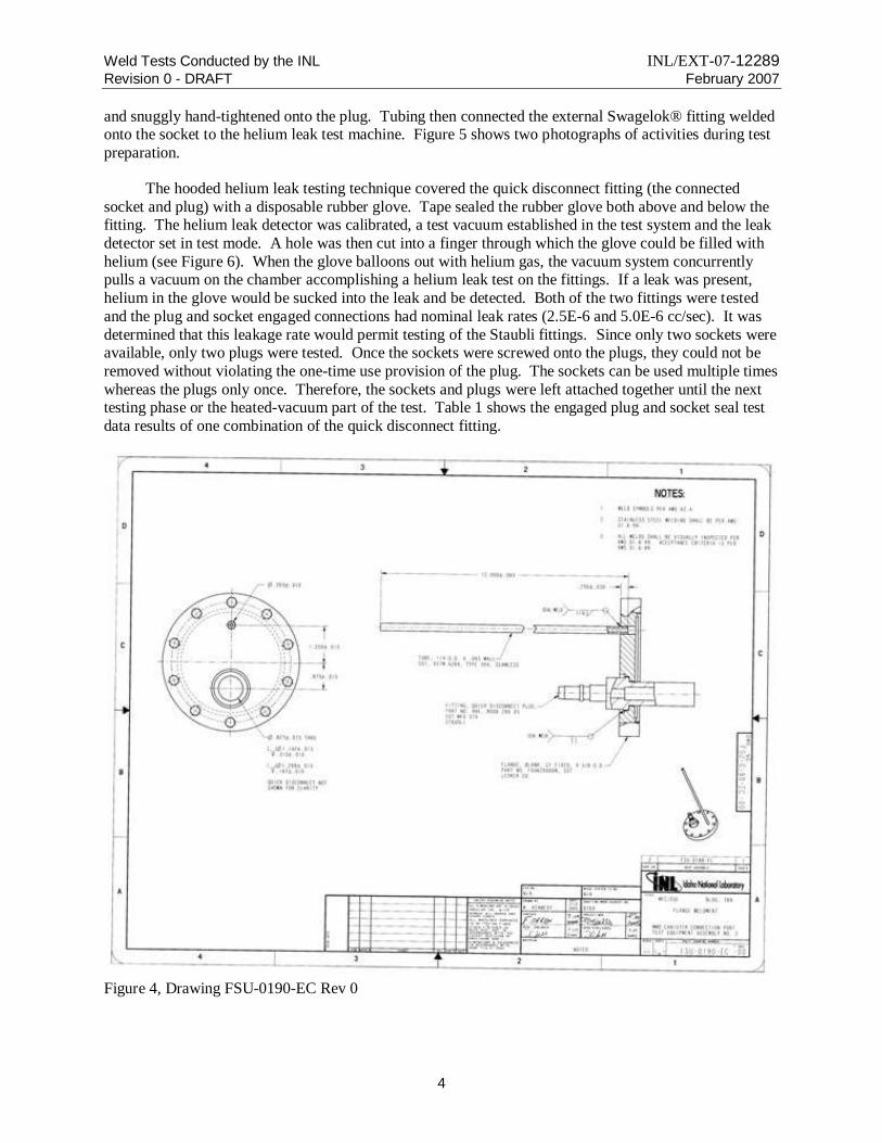
2005 Test Report, FSU-0192-ES-00, provides a detailed report of Staubli quick disconnect fitting test. To test the fittings, a 20 cubic in. test chamber with a flanged top was fabricated. The chamber was
fabricated with a standard ten-hole flange top opening. This permitted interchange of blank flanges, fitted
with different Staubli quick disconnect plugs, to be bolted to the chamber. The blank flanges were drilled
and machined to accept the Staubli plug and 0.25-in tubing. Figure 3 shows the test chamber a modified blank flange installed. Figure 4 shows details of a test flange.
Prior to heating the assembled test chamber, two plugs were welded to individual flanges, the
mating sockets engaged and helium leak tested. Both plugs indicated a leak rate greater than the acceptance criteria. Also two plugs, not welded to a flange, were also helium leak tested and indicated

Weld Tests Conducted by the INL INL/EXT-07-12289
Revision 0 - DRAFT February 2007
3
leakage. The testing was terminated. Upon analysis of the test results and an examination of the test hardware, it was discovered that the welding of the plugs was not as specified on the drawing. The test
flange was welded to the barrel of the plug and not to a machined weld preparation of the plug. The
Staubli representative suggested that the welding on the barrel of the plug may have annealed the spring.
The plug is to be welded only on the machined weld preparation at the top of the plug. The apparent leak test failure of the two un-welded plugs tested was determined to be acceptable since the plugs were never
intended to hold a leak tight seal without being previously engaged by the socket.
Since the 2005 test, the Staubli representative supplied the INL with four new prototypic plug fittings—two plugs with one proprietary internal seal material and two plugs with another proprietary
internal seal material—to be retested. The two socket fittings from the 2005 test were available for reuse
along with a fabricated test chamber. Before pertforming full scale heating and vacuum testing of the
fittings, it was decided to first evaluate the threaded seals between the plug and the socket. If those seals leak, then the Staubli quick disconnect fitting would not be useable for this project.
Figure 3, Drawing FSU-0188-EC Rev 0
Engaged Seal Test. The engaged seal test occurred at the INL Reactor Test Complex (RTC) in the inspection room of building RTC-638. Before this test, two plugs (ID number 1-263 and 1-265) were
welded onto the two separate blank flanges that fit the fabricated chamber. After the mating parts were
cleaned, the flange and copper gasket was bolted onto the chamber; the socket was threaded onto the plug
Weld Tests Conducted by the INL INL/EXT-07-12289
Revision 0 - DRAFT February 2007
4
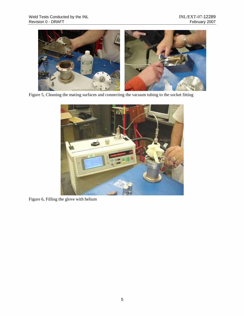
and snuggly hand-tightened onto the plug. Tubing then connected the external Swagelok® fitting welded onto the socket to the helium leak test machine. Figure 5 shows two photographs of activities during test
preparation.
The hooded helium leak testing technique covered the quick disconnect fitting (the connected
socket and plug) with a disposable rubber glove. Tape sealed the rubber glove both above and below the fitting. The helium leak detector was calibrated, a test vacuum established in the test system and the leak
detector set in test mode. A hole was then cut into a finger through which the glove could be filled with
helium (see Figure 6). When the glove balloons out with helium gas, the vacuum system concurrently pulls a vacuum on the chamber accomplishing a helium leak test on the fittings. If a leak was present,
helium in the glove would be sucked into the leak and be detected. Both of the two fittings were tested
and the plug and socket engaged connections had nominal leak rates (2.5E-6 and 5.0E-6 cc/sec). It was
determined that this leakage rate would permit testing of the Staubli fittings. Since only two sockets were available, only two plugs were tested. Once the sockets were screwed onto the plugs, they could not be
removed without violating the one-time use provision of the plug. The sockets can be used multiple times
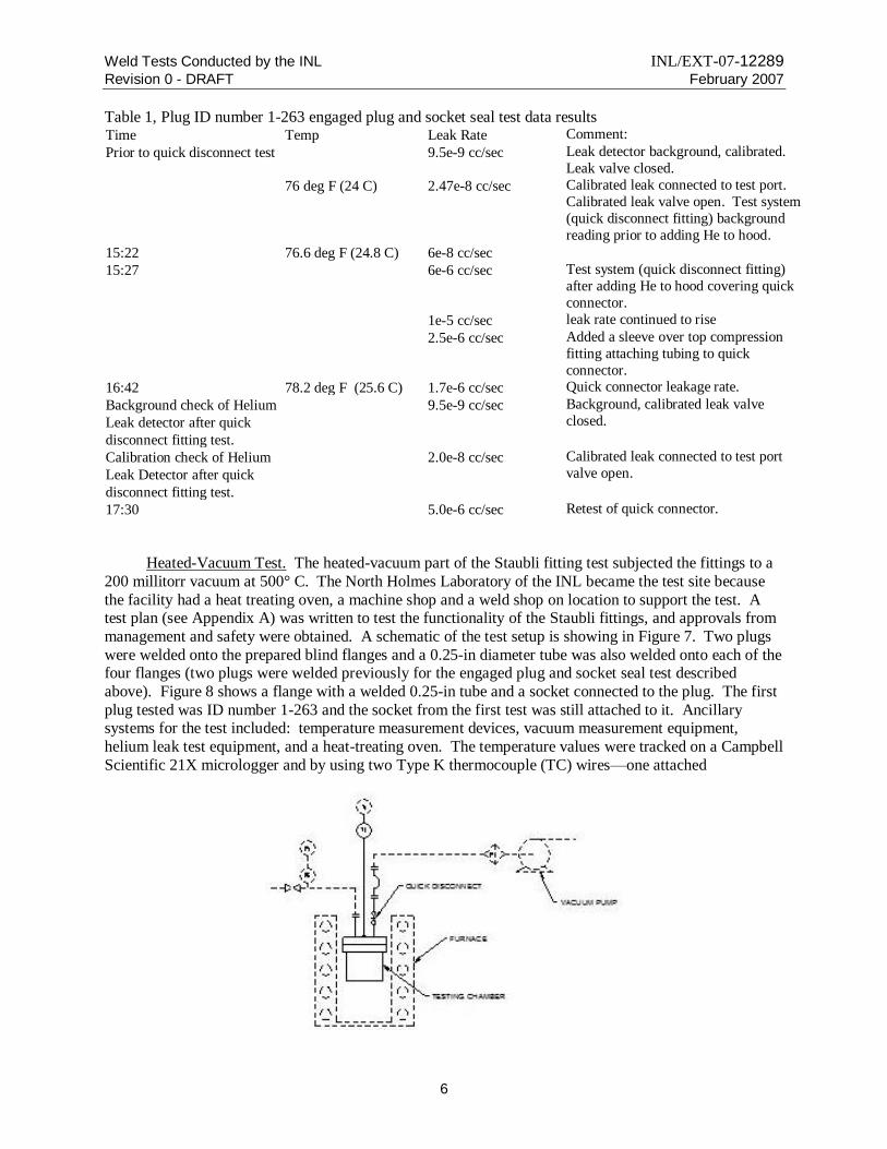
whereas the plugs only once. Therefore, the sockets and plugs were left attached together until the next testing phase or the heated-vacuum part of the test. Table 1 shows the engaged plug and socket seal test
data results of one combination of the quick disconnect fitting.
Figure 4, Drawing FSU-0190-EC Rev 0
Weld Tests Conducted by the INL INL/EXT-07-12289
Revision 0 - DRAFT February 2007
5
Figure 5, Cleaning the mating surfaces and connecting the vacuum tubing to the socket fitting
Figure 6, Filling the glove with helium
Weld Tests Conducted by the INL INL/EXT-07-12289
Revision 0 - DRAFT February 2007
6
Table 1, Plug ID number 1-263 engaged plug and socket seal test data results Time Temp Leak Rate Comment:
Prior to quick disconnect test 9.5e-9 cc/sec Leak detector background, calibrated.
Leak valve closed.
76 deg F (24 C) 2.47e-8 cc/sec Calibrated leak connected to test port.
Calibrated leak valve open. Test system
(quick disconnect fitting) background
reading prior to adding He to hood.
15:22 76.6 deg F (24.8 C) 6e-8 cc/sec
15:27 6e-6 cc/sec Test system (quick disconnect fitting)
after adding He to hood covering quick
connector.
1e-5 cc/sec leak rate continued to rise
2.5e-6 cc/sec Added a sleeve over top compression
fitting attaching tubing to quick
connector.
16:42 78.2 deg F (25.6 C) 1.7e-6 cc/sec Quick connector leakage rate.
Background check of Helium
Leak detector after quick
disconnect fitting test.
9.5e-9 cc/sec Background, calibrated leak valve
closed.
Calibration check of Helium
Leak Detector after quick
disconnect fitting test.
2.0e-8 cc/sec Calibrated leak connected to test port
valve open.
17:30 5.0e-6 cc/sec Retest of quick connector.
Heated-Vacuum Test. The heated-vacuum part of the Staubli fitting test subjected the fittings to a
200 millitorr vacuum at 500° C. The North Holmes Laboratory of the INL became the test site because
the facility had a heat treating oven, a machine shop and a weld shop on location to support the test. A test plan (see Appendix A) was written to test the functionality of the Staubli fittings, and approvals from
management and safety were obtained. A schematic of the test setup is showing in Figure 7. Two plugs
were welded onto the prepared blind flanges and a 0.25-in diameter tube was also welded onto each of the four flanges (two plugs were welded previously for the engaged plug and socket seal test described
above). Figure 8 shows a flange with a welded 0.25-in tube and a socket connected to the plug. The first
plug tested was ID number 1-263 and the socket from the first test was still attached to it. Ancillary systems for the test included: temperature measurement devices, vacuum measurement equipment,
helium leak test equipment, and a heat-treating oven. The temperature values were tracked on a Campbell
Scientific 21X micrologger and by using two Type K thermocouple (TC) wires—one attached
Weld Tests Conducted by the INL INL/EXT-07-12289
Revision 0 - DRAFT February 2007
7
Figure 7, Schematic of disconnect fitting test setup
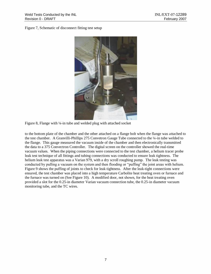
Figure 8, Flange with ¼-in tube and welded plug with attached socket
to the bottom plate of the chamber and the other attached on a flange bolt when the flange was attached to
the test chamber. A Granvilli-Phillips 275 Convetron Gauge Tube connected to the ¼-in tube welded to
the flange. This gauge measured the vacuum inside of the chamber and then electronically transmitted the data to a 375 Convectron Controller. The digital screen on the controller showed the real-time
vacuum values. When the piping connections were connected to the test chamber, a helium tracer probe
leak test technique of all fittings and tubing connections was conducted to ensure leak tightness. The helium leak test apparatus was a Varian 979, with a dry scroll roughing pump. The leak testing was
conducted by pulling a vacuum on the system and then flooding or “puffing” the joint areas with helium.
Figure 9 shows the puffing of joints to check for leak tightness. After the leak-tight connections were
ensured, the test chamber was placed into a high temperature Carbolite heat treating oven or furnace and the furnace was turned on (See Figure 10). A modified door, not shown, for the heat treating oven
provided a slot for the 0.25-in diameter Varian vacuum connection tube, the 0.25-in diameter vacuum
monitoring tube, and the TC wires.
Weld Tests Conducted by the INL INL/EXT-07-12289
Revision 0 - DRAFT February 2007
8
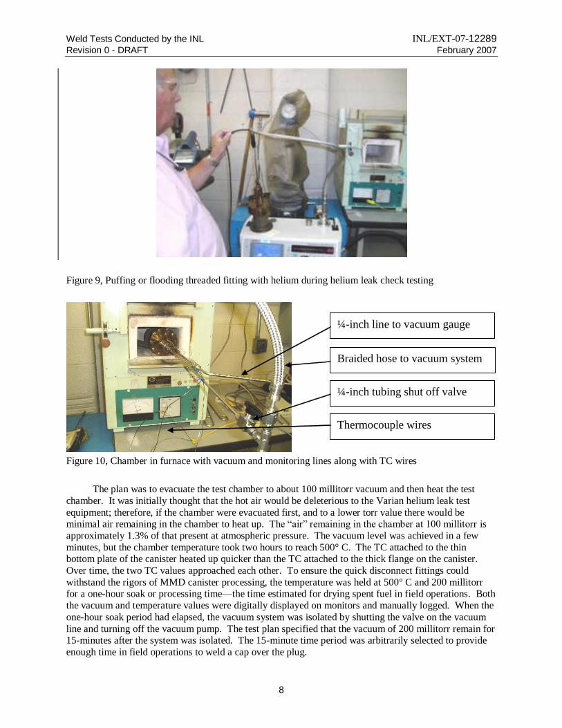
Figure 9, Puffing or flooding threaded fitting with helium during helium leak check testing
¼-inch line to vacuum gauge
Braided hose to vacuum system
¼-inch tubing shut off valve
Thermocouple wires
Figure 10, Chamber in furnace with vacuum and monitoring lines along with TC wires
The plan was to evacuate the test chamber to about 100 millitorr vacuum and then heat the test
chamber. It was initially thought that the hot air would be deleterious to the Varian helium leak test
equipment; therefore, if the chamber were evacuated first, and to a lower torr value there would be minimal air remaining in the chamber to heat up. The “air” remaining in the chamber at 100 millitorr is
approximately 1.3% of that present at atmospheric pressure. The vacuum level was achieved in a few
minutes, but the chamber temperature took two hours to reach 500° C. The TC attached to the thin bottom plate of the canister heated up quicker than the TC attached to the thick flange on the canister.
Over time, the two TC values approached each other. To ensure the quick disconnect fittings could
withstand the rigors of MMD canister processing, the temperature was held at 500° C and 200 millitorr for a one-hour soak or processing time—the time estimated for drying spent fuel in field operations. Both
the vacuum and temperature values were digitally displayed on monitors and manually logged. When the
one-hour soak period had elapsed, the vacuum system was isolated by shutting the valve on the vacuum
line and turning off the vacuum pump. The test plan specified that the vacuum of 200 millitorr remain for 15-minutes after the system was isolated. The 15-minute time period was arbitrarily selected to provide
enough time in field operations to weld a cap over the plug.

Weld Tests Conducted by the INL INL/EXT-07-12289
Revision 0 - DRAFT February 2007
9
It was anticipated that, after the ramp-up heating time and one hour at 500° C, the moisture and off-gassing would have been totally eliminated. But when the valve isolated the chamber, the canister
pressure increased at the rate of about 300 millitorr per minute for five minutes. Two more cycles of
achieving 200 millitorr vacuum followed by valve isolation were performed, with similar results. It
appeared that there was a leak in the system. Because it was late in the day, the valve was shut off to isolate the system, and all of the equipment was turned off. In the morning, the test chamber, heat-
treating furnace and connecting piping were cold (room temperature), but the vacuum gauges registered a
surprising 78 millitorr vacuum value. It was apparent that the system was not leaking. Something was causing gas evolution at the high test temperature condition, but condensed when cooled. [It should be
noted that the test chamber vacuum was achieved with the scroll pump associated with the helium leak
test device. Although functional, the helium leak test device consistently vented after pulling and holding
vacuum as low as 30 millitorr on the canister for several minutes. This would require intervention by the operator to re-initiate evacuation.]
After a short discussion between the team members at that time, the team decided to tear down the
system and clean all of the internal surfaces of the tubing and chamber. Figure 11 shows the cleaning operation. A slight amount of powdery debris was discovered in the canister when the flange was
removed. Figure 12 shows the debris. Acetone solvent, Q-tips on wooden sticks, gun barrel cleaning
patches, and wiping cloths were used to wipe down the inside surfaces of the tubing, canister and flanges before restarting the test. The internal surfaces of the 0.25-in tubes were also swabbed out and cleaned
using a thin welding wire and acetone soaked gun barrel cleaning patches. Efforts were taken to not leave
oily finger prints on any interior surface. Also to assist in reducing the evacuating time, the tubing
between the canister and the gauge tube and the tubing between the vacuum system and canister were shortened about 40-in. Initially it was thought that the radiant heat from the furnace and convective heat
along the tube would affect the gauge tube, but the two long tubes did not heat up significantly more than
a few of degrees outside of the furnace. Therefore the long tubes were not required and were thus trimmed off.
Figure 11, Cleaning parts and tubing Figure 12, Canister debris on a white sheet of paper
The test was restarted using another welded plug (ID number 1-265). It should be noted that this
plug (ID number 1-265) and the socket had been joined together or attached during the engaged plug and socket seal test described above. The fittings and connections were all tightened prior to being leak
checked. It was discovered that the socket had become un-threaded several turns from the plug. The
socket was re-tightened onto the plug. During the leak check, this plug and socket combination could not hold a leak tight seal. The flange with plug (ID number 1-265) was unbolted and removed from the
canister.
Weld Tests Conducted by the INL INL/EXT-07-12289
Revision 0 - DRAFT February 2007
10
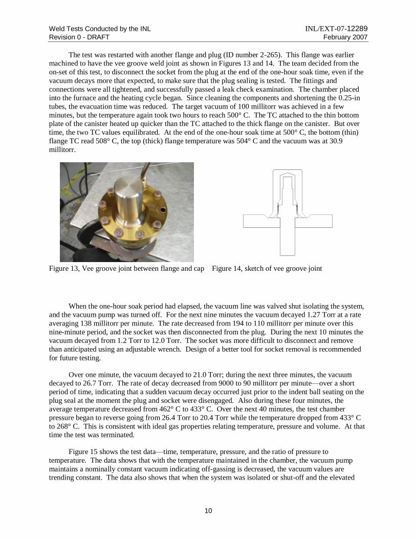
The test was restarted with another flange and plug (ID number 2-265). This flange was earlier machined to have the vee groove weld joint as shown in Figures 13 and 14. The team decided from the
on-set of this test, to disconnect the socket from the plug at the end of the one-hour soak time, even if the
vacuum decays more that expected, to make sure that the plug sealing is tested. The fittings and
connections were all tightened, and successfully passed a leak check examination. The chamber placed into the furnace and the heating cycle began. Since cleaning the components and shortening the 0.25-in
tubes, the evacuation time was reduced. The target vacuum of 100 millitorr was achieved in a few
minutes, but the temperature again took two hours to reach 500° C. The TC attached to the thin bottom plate of the canister heated up quicker than the TC attached to the thick flange on the canister. But over
time, the two TC values equilibrated. At the end of the one-hour soak time at 500° C, the bottom (thin)
flange TC read 508° C, the top (thick) flange temperature was 504° C and the vacuum was at 30.9
millitorr.
Figure 13, Vee groove joint between flange and cap Figure 14, sketch of vee groove joint
When the one-hour soak period had elapsed, the vacuum line was valved shut isolating the system, and the vacuum pump was turned off. For the next nine minutes the vacuum decayed 1.27 Torr at a rate
averaging 138 millitorr per minute. The rate decreased from 194 to 110 millitorr per minute over this
nine-minute period, and the socket was then disconnected from the plug. During the next 10 minutes the vacuum decayed from 1.2 Torr to 12.0 Torr. The socket was more difficult to disconnect and remove
than anticipated using an adjustable wrench. Design of a better tool for socket removal is recommended
for future testing.
Over one minute, the vacuum decayed to 21.0 Torr; during the next three minutes, the vacuum decayed to 26.7 Torr. The rate of decay decreased from 9000 to 90 millitorr per minute—over a short
period of time, indicating that a sudden vacuum decay occurred just prior to the indent ball seating on the
plug seal at the moment the plug and socket were disengaged. Also during these four minutes, the average temperature decreased from 462° C to 433° C. Over the next 40 minutes, the test chamber
pressure began to reverse going from 26.4 Torr to 20.4 Torr while the temperature dropped from 433° C
to 268° C. This is consistent with ideal gas properties relating temperature, pressure and volume. At that time the test was terminated.
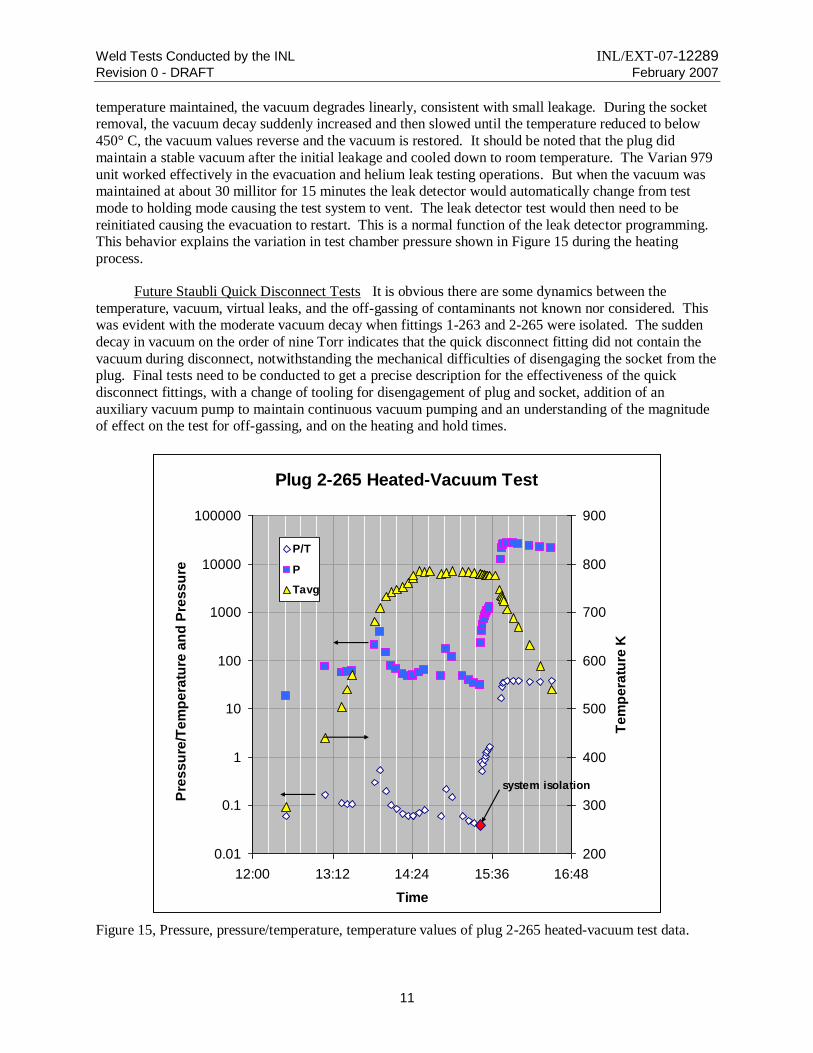
Figure 15 shows the test data—time, temperature, pressure, and the ratio of pressure to
temperature. The data shows that with the temperature maintained in the chamber, the vacuum pump
maintains a nominally constant vacuum indicating off-gassing is decreased, the vacuum values are trending constant. The data also shows that when the system was isolated or shut-off and the elevated
Weld Tests Conducted by the INL INL/EXT-07-12289
Revision 0 - DRAFT February 2007
11
temperature maintained, the vacuum degrades linearly, consistent with small leakage. During the socket removal, the vacuum decay suddenly increased and then slowed until the temperature reduced to below
450° C, the vacuum values reverse and the vacuum is restored. It should be noted that the plug did
maintain a stable vacuum after the initial leakage and cooled down to room temperature. The Varian 979
unit worked effectively in the evacuation and helium leak testing operations. But when the vacuum was maintained at about 30 millitor for 15 minutes the leak detector would automatically change from test
mode to holding mode causing the test system to vent. The leak detector test would then need to be
reinitiated causing the evacuation to restart. This is a normal function of the leak detector programming. This behavior explains the variation in test chamber pressure shown in Figure 15 during the heating
process.
Future Staubli Quick Disconnect Tests It is obvious there are some dynamics between the
temperature, vacuum, virtual leaks, and the off-gassing of contaminants not known nor considered. This was evident with the moderate vacuum decay when fittings 1-263 and 2-265 were isolated. The sudden
decay in vacuum on the order of nine Torr indicates that the quick disconnect fitting did not contain the
vacuum during disconnect, notwithstanding the mechanical difficulties of disengaging the socket from the plug. Final tests need to be conducted to get a precise description for the effectiveness of the quick
disconnect fittings, with a change of tooling for disengagement of plug and socket, addition of an
auxiliary vacuum pump to maintain continuous vacuum pumping and an understanding of the magnitude of effect on the test for off-gassing, and on the heating and hold times.
Plug 2-265 Heated-Vacuum Test
0.01
0.1
1
10
100
1000
10000
100000
12:00 13:12 14:24 15:36 16:48
Time
Pre
ss
ure
/Te
mp
era
ture
an
d P
res
su
re
200
300
400
500
600
700
800
900
Te
mp
era
ture
K
P/T
P
Tavg
system isolation
Figure 15, Pressure, pressure/temperature, temperature values of plug 2-265 heated-vacuum test data.
Weld Tests Conducted by the INL INL/EXT-07-12289
Revision 0 - DRAFT February 2007
12
3. Weld Issues
Print FSU—0177-EC-02, FSU Plug, Canister Shielding shows the following welding details for the
MMD canister:
The closure groove weld between the top of the canister and the top plate of the shielding plug
The Staubli quick disconnect plug weld onto the top plate of the shield plug
The Staubli quick disconnect plug cap weld onto the shield plug
The fillet weld on the lifting lug
The notations relating to the welding code citations
Upon examination of the earlier version (FSU—0177-EC-01), it became evident that changes were
necessary.
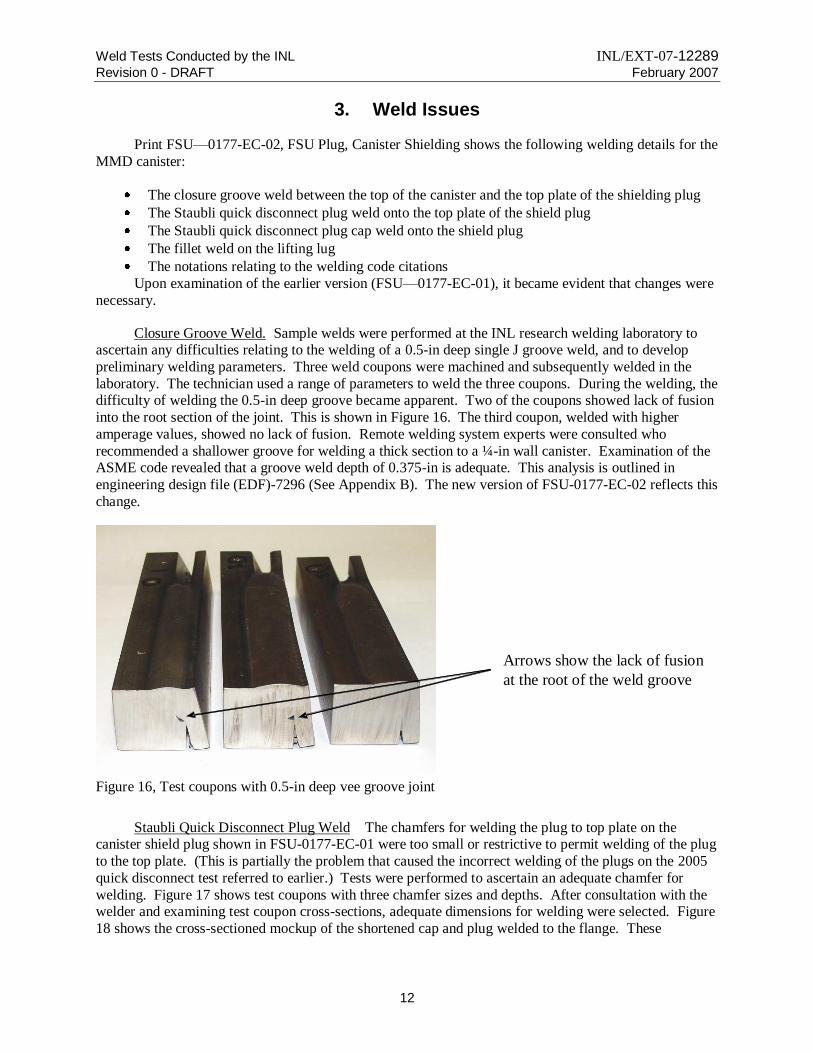
Closure Groove Weld. Sample welds were performed at the INL research welding laboratory to ascertain any difficulties relating to the welding of a 0.5-in deep single J groove weld, and to develop
preliminary welding parameters. Three weld coupons were machined and subsequently welded in the
laboratory. The technician used a range of parameters to weld the three coupons. During the welding, the difficulty of welding the 0.5-in deep groove became apparent. Two of the coupons showed lack of fusion
into the root section of the joint. This is shown in Figure 16. The third coupon, welded with higher
amperage values, showed no lack of fusion. Remote welding system experts were consulted who
recommended a shallower groove for welding a thick section to a ¼-in wall canister. Examination of the ASME code revealed that a groove weld depth of 0.375-in is adequate. This analysis is outlined in
engineering design file (EDF)-7296 (See Appendix B). The new version of FSU-0177-EC-02 reflects this
change.
Figure 16, Test coupons with 0.5-in deep vee groove joint
Staubli Quick Disconnect Plug Weld The chamfers for welding the plug to top plate on the canister shield plug shown in FSU-0177-EC-01 were too small or restrictive to permit welding of the plug
to the top plate. (This is partially the problem that caused the incorrect welding of the plugs on the 2005
quick disconnect test referred to earlier.) Tests were performed to ascertain an adequate chamfer for
welding. Figure 17 shows test coupons with three chamfer sizes and depths. After consultation with the welder and examining test coupon cross-sections, adequate dimensions for welding were selected. Figure
18 shows the cross-sectioned mockup of the shortened cap and plug welded to the flange. These
Arrows show the lack of fusion
at the root of the weld groove

Weld Tests Conducted by the INL INL/EXT-07-12289
Revision 0 - DRAFT February 2007
13
dimensions were also used on the blank flange/plug weld required for the heated vacuum test. The new version of FSU-0177-EC-02 reflects the correct chamfer dimensions.
Shorted cap that
simulates full size cap
Shortened plugs that
simulates full size plug
Welded shortened plug
into simulated flange
Shorted cap that
simulates full size cap
Shortened plugs that
simulates full size plug
Welded shortened plug
into simulated flange
Figure 17, Three test coupons with different chamfer sizes and depths
Figure 18, Cross-section of mockup sample in a milling machine vise
Staubli Quick Disconnect Plug Cap Weld As previously discussed, after the canister has been
heated to 500° C and held at 200 millitorr, the socket is disconnected. As soon as possible after the
disconnection, a cap was threaded onto the plug seating tightly onto the blank flange, and welded. The welded cap ensures the negative pressure or vacuum is maintained, it protects the plug from potential

Weld Tests Conducted by the INL INL/EXT-07-12289
Revision 0 - DRAFT February 2007
14
damage during canister handling, and it serves as a secondary pressure boundary covering the plug in the event of plug failure,. Initially the cap and weld joint were designed for a fillet weld, but the code
requires a groove weld joint for this weld. Therefore, both the cap and the top cover plate design were
revised to facilitate the groove weld joint. The EDF-7296 calculations allow for a maximum groove
depth of 0.173-in, and show that a 1/16-in fillet weld provides sufficient strength for the attachment of the cap to the canister top cover plate. A plug cap and flange consistent with these specifications were used
in the heated/vacuum test to demonstrate a vee groove joint between the cap and flange. Figure 14 shows
a sketch of the cap with plug and flange and vee groove weld joint. The cap was designed to thread onto the plug. This ensures the cap does not shift during weld tack welding. Figure 13 shows the vee groove
joint between the cap and the flange prior to welding. This flange shows discoloration due to heating in
the furnace. The new version of FSU-0177-EC-02 reflects the 0.15-in deep vee groove.
Following the cap welding, the cap weld shall be helium leak tested to meet the code requirements for a closure weld. At the end of the heated/vacuum test, the cap weld was helium leak checked to
validate the inspectability of the weld. The helium leak test inspection fixture setting on over the cap
weld is shown in Figure 19.
The flange, plug, and cap from the heated/vacuum test were cross-sectioned to secure a
metallographic sample to assess both the plug to flange and cap to flange welds. A photograph of this
metallographic sample is shown is Figure 20. The weld cap has a minimum wall thickness of 0.25-in to match that of the canister, and to withstand the maximum internal pressure of 57.3 pounds per square in.
Figure 19, Helium leak check chamber setting over the cap-to-flange-weld

Weld Tests Conducted by the INL INL/EXT-07-12289
Revision 0 - DRAFT February 2007
15
Flange
Plug
Fitting Cap
Cap to Flange Weld, two passes
Plug to Flange Weld
Figure 20, Cross section showing welds connecting the plug to flange and cap to flange
Lifting Lug Weld On drawing FSU—0177-EC-01, a lifting eye is shown welded onto the top plate
of the shield plug. A lifting eye is hard to use in a remote handing operation. The new version of FSU-0177-EC-02 reflects the pintle lifting point. The 3/16-in fillet weld attaching the pintle is equivalent in
length to the lifting eye weld. Therefore no weld strength analysis was performed, but the EDF
documentation shows that the weld and top cover plate are adequate for the loads.
Drawing Changes The work on the MMD project at the INL in 2006 generated some changes to the canister drawings. Some changes are minor while others are substantial. The drawings changed
include:
FSU-0173-ED-01, FSU MMD Prototype Canister/Liner Assembly
FSU-0174-ED-01, FSU Liner MMD Prototype Canister/Liner Assembly
FSU-0173-ED-01, FSU Plug, Canister Shielding MMD Prototype Canister/Liner Assembly
Copies of the revised drawing are located in Appendix C.
4. Canister Connection Port Tube Welding
Tube Pin Welding Several options for canister connection port closures are suggested in FSU-
0165-ES-00, Canister Connection Port Options Study. The port closure option of choice from this study
was the prototype quick disconnect fitting developed by Staubli with a welded cap. However, the testing
done at the INL in 2006 was not conclusive that the quick disconnect fitting functions in the manner required. As stated earlier in this document, more testing with a larger sample size needs to be conducted.
The Hydraulic Crimper and Welder option was also suggested in the Options Study. In this option, a tube
extends from the top of the canister and a device, using hydraulics and a power supply, crimps the tube, resistance welds it shut, and then cuts off the tube. A modification of this option was to crimp the tube,
pin weld the tube and sever the tube using a commercially off-the-shelf available resistance welder.
Tests conducted over two days at the Centerline Special Machinery Division in Windsor, Ontario, Canada demonstrated the feasibility of pin welding stainless steel tubing. Centerline supplies resistance
welding equipment to the manufacturing and automotive industry, and since they once successfully
developed equipment to weld stainless steel nuclear fuel rods or elements to the INL, it was thought that
one of their many machines could be adapted to pin weld stainless steel tubing.
Weld Tests Conducted by the INL INL/EXT-07-12289
Revision 0 - DRAFT February 2007
16
Preliminary tests performed by Centerline validated the process before conducting the feasibility test. Their preliminary tests demonstrated that pin welding was possible with their machines. For the
feasibility testing, Centerline provided two technicians, welding equipment, and a plethora of senior
engineers that would periodically stop by the test cell and consult with the team. The primary tasks of the
feasibility testing were to develop:
A welding schedule for each of the three tubing sizes: 0.25-in, 0.375-in, and 0.5-in tubes. (All
tubes have the same 0.035-in wall thickness.)
A severing schedule to separate or sever the tube on each of the three tubing sizes: 0.25-in,
0.375-in, and 0.5-in tubes.
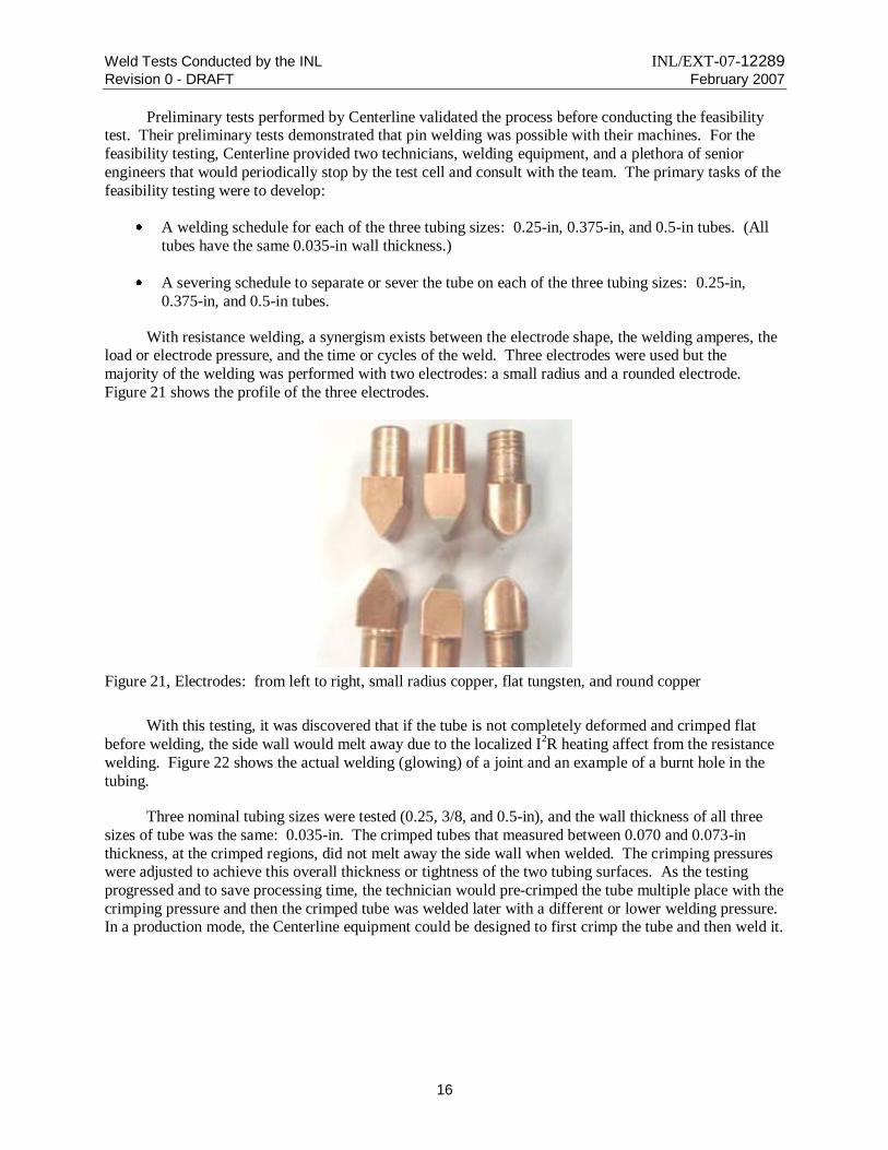
With resistance welding, a synergism exists between the electrode shape, the welding amperes, the load or electrode pressure, and the time or cycles of the weld. Three electrodes were used but the
majority of the welding was performed with two electrodes: a small radius and a rounded electrode.
Figure 21 shows the profile of the three electrodes.
Figure 21, Electrodes: from left to right, small radius copper, flat tungsten, and round copper
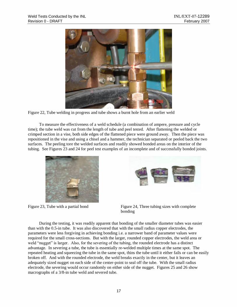
With this testing, it was discovered that if the tube is not completely deformed and crimped flat
before welding, the side wall would melt away due to the localized I2R heating affect from the resistance
welding. Figure 22 shows the actual welding (glowing) of a joint and an example of a burnt hole in the
tubing.
Three nominal tubing sizes were tested (0.25, 3/8, and 0.5-in), and the wall thickness of all three
sizes of tube was the same: 0.035-in. The crimped tubes that measured between 0.070 and 0.073-in
thickness, at the crimped regions, did not melt away the side wall when welded. The crimping pressures were adjusted to achieve this overall thickness or tightness of the two tubing surfaces. As the testing
progressed and to save processing time, the technician would pre-crimped the tube multiple place with the
crimping pressure and then the crimped tube was welded later with a different or lower welding pressure. In a production mode, the Centerline equipment could be designed to first crimp the tube and then weld it.
Weld Tests Conducted by the INL INL/EXT-07-12289
Revision 0 - DRAFT February 2007
17
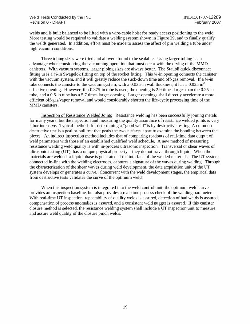
Figure 22, Tube welding in progress and tube shows a burnt hole from an earlier weld
To measure the effectiveness of a weld schedule (a combination of ampere, pressure and cycle time); the tube weld was cut from the length of tube and peel tested. After flattening the welded or
crimped section in a vise, both side edges of the flattened piece were ground away. Then the piece was
repositioned in the vise and using a chisel and a hammer, the technician separated or peeled back the two surfaces. The peeling tore the welded surfaces and readily showed bonded areas on the interior of the
tubing. See Figures 23 and 24 for peel test examples of an incomplete and of successfully bonded joints.
Figure 23, Tube with a partial bond Figure 24, Three tubing sizes with complete bonding
During the testing, it was readily apparent that bonding of the smaller diameter tubes was easier
than with the 0.5-in tube. It was also discovered that with the small radius copper electrodes, the parameters were less forgiving in achieving bonding i.e. a narrower band of parameter values were
required for the small cross-sections. But with the larger, rounded copper electrodes, the weld area or
weld “nugget” is larger. Also, for the severing of the tubing, the rounded electrode has a distinct
advantage. In severing a tube, the tube is essentially re-welded multiple times at the same spot. The repeated heating and squeezing the tube in the same spot, thins the tube until it either fails or can be easily
broken off. And with the rounded electrode, the weld breaks exactly in the center, but it leaves an
adequately sized nugget on each side of the center-point to seal off the tube. With the small radius electrode, the severing would occur randomly on either side of the nugget. Figures 25 and 26 show
macrographs of a 3/8-in tube weld and severed tube.

Weld Tests Conducted by the INL INL/EXT-07-12289
Revision 0 - DRAFT February 2007
18
Figure 25, 0.375-in welded tube (0.035-in wall) Figure 26, 0.375-in severed tube (0.035-in wall)
Once a set of optimum parameters were established, they were easily adapted (reduced or
increased) for other tube sizes. Figure 24 shows a successful peel example of each tubing size. A record
of the weld schedules that produced welds showing solid bonding with peel tests are listed in Appendix
D: Pinch Weld Schedule Summary. Figures 27 and 28 show etched macro-photographs of selected welds. The photographs show distinct bonding of the tubing internal surfaces.
Figure 27, Cross-weld cut on ½-in tube weld Figure 28, Cross-tube cut through ¼-in tube weld
The essential parameters for welding the 0.5-in tube with the rounded electrode includes 2000
pounds of force, with 17,000 amperes and for 96-cycles (1.36 seconds) total weld and cool/hold times.
Part of the success of pin welding the tubes with the Centerline controllers was their ability to allow welding with impulse cycles. For the complete impulse weld cycle for the ½-in tube, the machine welds
with the established force and amperes for five cycles and then cools or holds for four cycle, then welds
for 15 cycles and holds for four cycles, welds again for 15 cycles and holds for four cycles, welds for 15 cycles and holds for 30 cycles. This impulse welding cycle allows the weld nugget to grow without
burning the edges of the tube.
Resistance welding of small tubes (1/8-in) has been used for years in nuclear applications, but the
testing at Centerline proved the feasibility of resistance welding of larger sized tubes. This Centerline welding was conducted with a stationary unit, but since Centerline provides many portable welding
systems to the automotive industry, one of their portable systems could be adapted to perform the tube
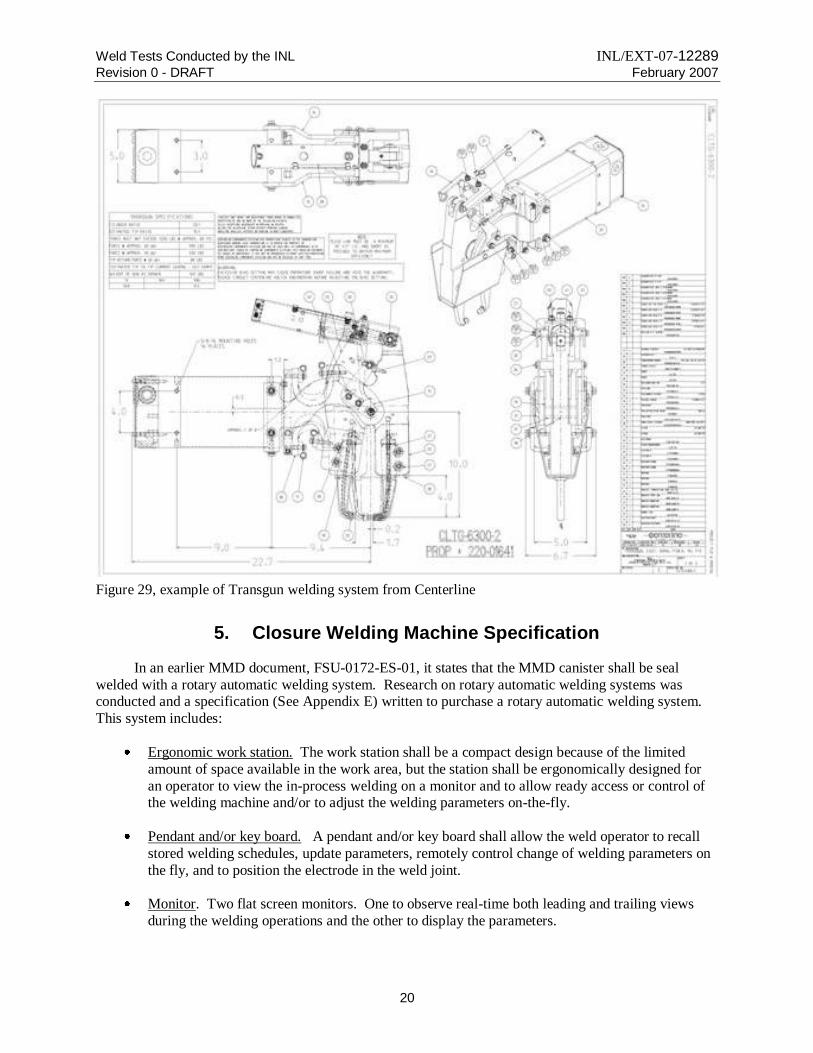
closer welding. An example of a commercially available system is shown in Figure 29. This machine has pin arms that would extend down into or through the furnace shielding shroud to access the tube sticking
out from the canister shield plug. The robust Centerline machine is designed to produce thousands of
Weld Tests Conducted by the INL INL/EXT-07-12289
Revision 0 - DRAFT February 2007
19
welds and is built balanced to be lifted with a wire-cable hoist for ready access positioning to the weld. More testing would be required to validate a welding system shown in Figure 29, and to finally qualify
the welds generated. In addition, effort must be made to assess the affect of pin welding a tube under
high vacuum conditions.
Three tubing sizes were tried and all were found to be sealable. Using larger tubing is an advantage when considering the vacuuming operation that must occur with the drying of the MMD
canisters. With vacuum systems, larger piping sizes are always better. The Staubli quick disconnect
fitting uses a ¼-in Swagelok fitting on top of the socket fitting. This ¼-in opening connects the canister with the vacuum system, and it will greatly reduce the suck-down time and off-gas removal. If a ¼-in
tube connects the canister to the vacuum system, with a 0.035-in wall thickness, it has a 0.025 in2
effective opening. However, if a 0.375-in tube is used, the opening is 2.9 times larger than the 0.25-in
tube, and a 0.5-in tube has a 5.7 times larger opening. Larger openings shall directly accelerate a more efficient off-gas/vapor removal and would considerably shorten the life-cycle processing time of the
MMD canisters.
Inspection of Resistance Welded Joints Resistance welding has been successfully joining metals for many years, but the inspection and measuring the quality assurance of resistance welded joints is very
labor intensive. Typical methods for determining a “good weld” is by destructive testing. A common
destructive test is a peal or pull test that peals the two surfaces apart to examine the bonding between the pieces. An indirect inspection method includes that of comparing readouts of real-time data output of
weld parameters with those of an established qualified weld schedule. A new method of measuring
resistance welding weld quality is with in-process ultrasonic inspection. Transversal or shear waves of
ultrasonic testing (UT), has a unique physical property—they do not travel through liquid. When the materials are welded, a liquid phase is generated at the interface of the welded materials. The UT system,
connected in-line with the welding electrodes, captures a signature of the waves during welding. Through
the characterization of the shear waves during weld development, the data acquisition unit of the UT system develops or generates a curve. Concurrent with the weld development stages, the empirical data
from destructive tests validates the curve of the optimum weld.
When this inspection system is integrated into the weld control unit, the optimum weld curve provides an inspection baseline, but also provides a real-time process check of the welding parameters.
With real-time UT inspection, repeatability of quality welds is assured, detection of bad welds is assured,
compensation of process anomalies is assured, and a consistent weld nugget is assured. If this canister
closure method is selected, the resistance welding system shall include a UT inspection unit to measure and assure weld quality of the closure pinch welds.
Weld Tests Conducted by the INL INL/EXT-07-12289
Revision 0 - DRAFT February 2007
20
Figure 29, example of Transgun welding system from Centerline
5. Closure Welding Machine Specification
In an earlier MMD document, FSU-0172-ES-01, it states that the MMD canister shall be seal
welded with a rotary automatic welding system. Research on rotary automatic welding systems was conducted and a specification (See Appendix E) written to purchase a rotary automatic welding system.
This system includes:
Ergonomic work station. The work station shall be a compact design because of the limited
amount of space available in the work area, but the station shall be ergonomically designed for
an operator to view the in-process welding on a monitor and to allow ready access or control of the welding machine and/or to adjust the welding parameters on-the-fly.
Pendant and/or key board. A pendant and/or key board shall allow the weld operator to recall
stored welding schedules, update parameters, remotely control change of welding parameters on
the fly, and to position the electrode in the weld joint.
Monitor. Two flat screen monitors. One to observe real-time both leading and trailing views
during the welding operations and the other to display the parameters.

Weld Tests Conducted by the INL INL/EXT-07-12289
Revision 0 - DRAFT February 2007
21
Power supply. A solid state, 480 volts, 3 phase, 60 hz, no high frequency arc starting, 100% duty
cycle, 300 to 400 ampere power supply to produce the weld. The power supply shall have pulsing capability. The power supply unit shall have wheels/casters and lifting lugs.
Computer/control console. A computer operating system capable of a “Windows” type
operating system to record and maintain the welding schedules. Controls to perform typical
rotary automatic welding include: current pulsing, oscillation, wire feed rates, torch travel
speeds, and amperages. The console shall incorporate a microprocessor controller with closed-loop feedback to the power supply, be capable of recording and storing welding programs. Also
shall have an e-stop, control of displays, and have real-time override of welding parameters.
Data acquisition. The computer systems shall have a digital data acquisition capability to record
the leading and trailing views of the weld pool, and a data logger to record actual weld parameters.
Printer. A printer to print the weld parameters, data log and welding history.
Software. Software program to manage the weld schedules, weld operation, data logging, and
inspections.
Vision system: The vision system shall have at a minimum: 1. The vision system shall provide
two cameras to track the electrode in the joint showing both a leading and trailing view of the weld pool and electrode during welding. 2. The vision system shall have at a minimum a 1.5-in
field of view with a 768 by 492 pixel or better rating, and 3. The vision system shall provide
video optics system to record and capture the real-time welding operations on a video tape or
CD.
Wire feed. Wire feed system drive rolls provide consistently feed wire into the weld pool. The
wire rolls shall be of adequate size to complete at a minimum one weld joint. The wire feed
system shall handle wire sizes between 0.030 and 0.045-in diameter, have a wire straightener,
have a 5 to 150 IPM wire feed speed, have an on-the-fly adjustable wire guide, and shall have programmable pulse-sync, run-in upslope, run-out down-slope and crater fill options.
Torch. The torch shall be at a minimum a 300 ampere water cooled torch. The cooling system
shall have a holding tank with a recirculation pump. Torch height is positioned by arc length
control with a programmable arc voltage control (AVC) with an accuracy of +/- 1% or 0.1 VDC
or which ever is greater.
Arc starting. The welding system shall have a touch arc start system.
Rotary welding system. Welding system shall fit on top of the 10.625-in diameter top cover
plate of the shield plug. The electrode must rotate around the 11.25-in diameter canister and
weld the single J groove joint between the shield plug and canister wall. The system must have a
minimum of 1.0-in axial torch movement, and have torch or arc oscillation. The end plate has 2.25-in tall pintle in the center that can be used as a centering device, but there is also an
obstruction on the top cover plate—the purge port fitting.
Support hardware. The welding system shall include all of the interconnections, assemblies,
electrical interfaces, wires, hoses, connections and parts needed to perform repeatable precision welds in a field environment.
Weld Tests Conducted by the INL INL/EXT-07-12289
Revision 0 - DRAFT February 2007
22
Shipping container. The shipping container shall be an industrial type shipping container that is
dust and weather proof. The container shall be a molded plastic, fiberglass, or metal. The containers shall have handles along with metal hinges and latches. The containers shall have a
mechanism for locking or securing with a padlock or other locking device.
Spare parts/tools. List of a spare parts and tools for the welding system.
Parts list of the whole system. List of parts.
The power requirements for a typical welding power supply would not exceed 28 amperes at 480
vac/3-phase and the operator workstation would not exceed 20-amperes at 120vac.
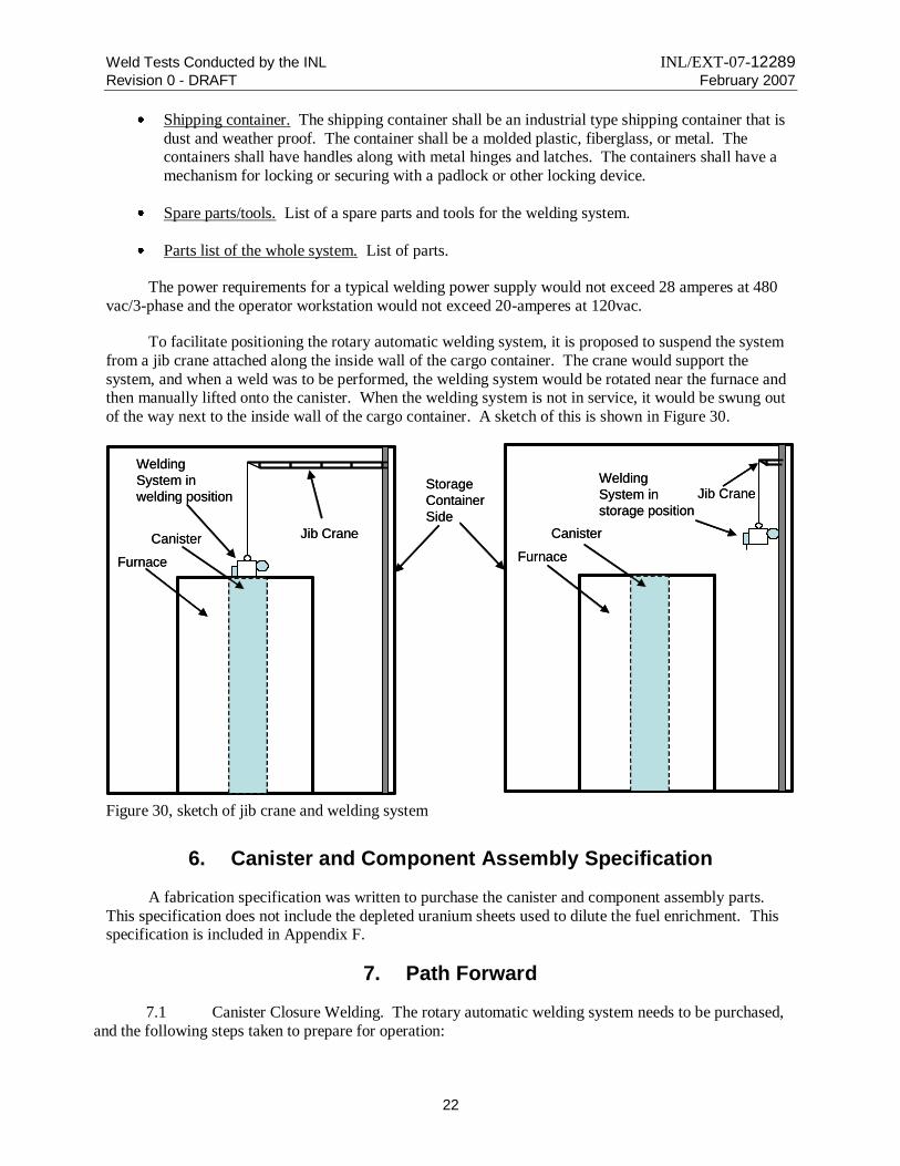
To facilitate positioning the rotary automatic welding system, it is proposed to suspend the system
from a jib crane attached along the inside wall of the cargo container. The crane would support the
system, and when a weld was to be performed, the welding system would be rotated near the furnace and then manually lifted onto the canister. When the welding system is not in service, it would be swung out
of the way next to the inside wall of the cargo container. A sketch of this is shown in Figure 30.
Furnace
Jib Crane
Welding
System in
welding position
Canister
Furnace
Jib CraneWelding
System in
storage position
Canister
Storage
Container
Side
Furnace
Jib Crane
Welding
System in
welding position
Canister
Furnace
Jib CraneWelding
System in
storage position
Canister
Storage
Container
Side
Figure 30, sketch of jib crane and welding system
6. Canister and Component Assembly Specification
A fabrication specification was written to purchase the canister and component assembly parts.
This specification does not include the depleted uranium sheets used to dilute the fuel enrichment. This specification is included in Appendix F.
7. Path Forward
7.1 Canister Closure Welding. The rotary automatic welding system needs to be purchased,
and the following steps taken to prepare for operation:

Weld Tests Conducted by the INL INL/EXT-07-12289
Revision 0 - DRAFT February 2007
23
Operation of the rotary automatic welding system needs to be verified and validated with
operational tests using mock-ups and test coupons.
Training on the rotary automatic welding system needs to be conducted.
Performing the cap weld needs to be assessed to ascertain if it can be performed manually or if it
should be done with an automatic system.
7.2 Evacuation Port Closure. When the decision is made to proceed with the MMD system, a
decision would be required, whether to utilize the Staubli quick disconnect fitting to close the evacuation
port, or whether the pinch weld system would be more suitable. This would be a largely economic decision, based upon the number of canisters to be processed. Staubli fittings are estimated to cost
$1000.00 each, but require very little special tooling. The pinch weld approach, on the other hand, requires
essentially no material, but the machine is estimated to cost $30,000.00. The path forward, then, depends upon the option selected.
7.2.1 Staubli Quick Disconnect Fitting:
Purchase and test samples to verify that the production item performs adequately.
Develop a tool to un-screw the socket quickly.
Perform testing to assess the cleanliness levels and cleaning techniques for the tubes and parts in maintaining the vacuum levels.
7.2.2 Tube Pin Welding
Develop an optimum weld schedule using peal test and macro examinations.
Consider deploying real-time UT inspection of the pin weld.
Procure resistance welding and, if appropriate, UT inspection systems.
Develop inspection and operational curves as standards for the UT system.
Perform all welds under mock up conditions to ensure the welding can be performed in the field
configuration.
Conduct tube pin welding (“pinch weld”) with the tube and canister under high vacuum to
validate procedures.