Embed Size (px)
Citation preview
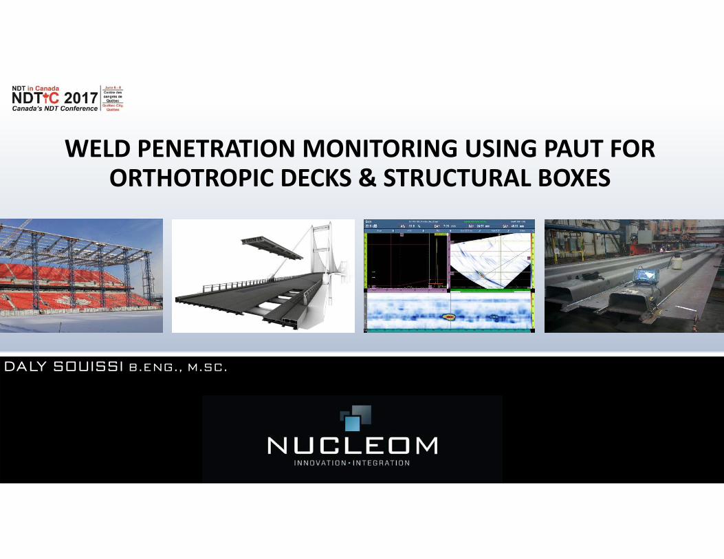
WELD PENETRATION MONITORING USING PAUT FOR ORTHOTROPIC DECKS & STRUCTURAL BOXES
D A LY S O U I S S I B . E N G . , M . S C .
©Nucleom inc.2
Presentation overview
Introduction
Standard/client specification
PAUT description
Inspection methodology
Validation
Encoding
Reporting
Conclusion
©Nucleom inc.3
Introduction
Weld penetration monitoring alternatives
Destructive testing (Macro etch testing): Involves sectioning and/or breaking
the welded section.
Conventional UT: Several limitations (Poor beam coverage, unreasonable
inspection time, subjective interpretation, etc.)
Phased Array UT: Large beam coverage, recordable data, multiple views,
repeatability, etc.
©Nucleom inc.4
Introduction
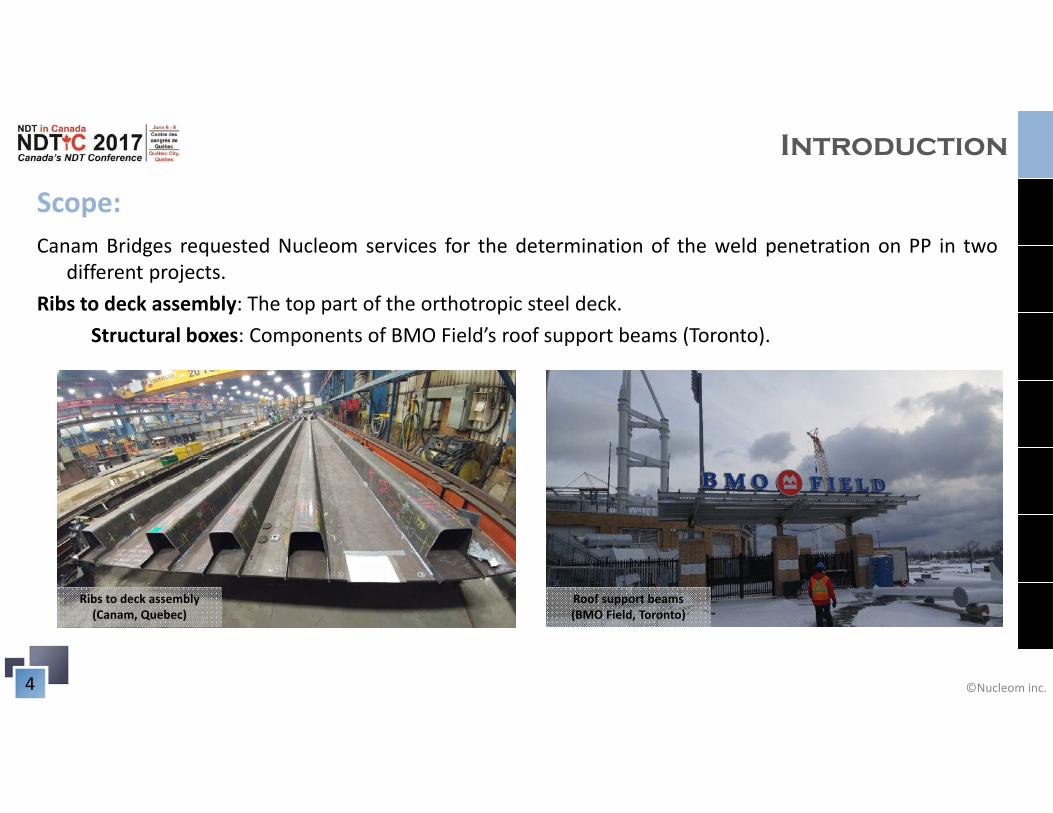
Scope:Canam Bridges requested Nucleom services for the determination of the weld penetration on PP in two
different projects.Ribs to deck assembly: The top part of the orthotropic steel deck.
Structural boxes: Components of BMO Field’s roof support beams (Toronto).
Ribs to deck assembly (Canam, Quebec)
Roof support beams(BMO Field, Toronto)
©Nucleom inc.5
Introduction
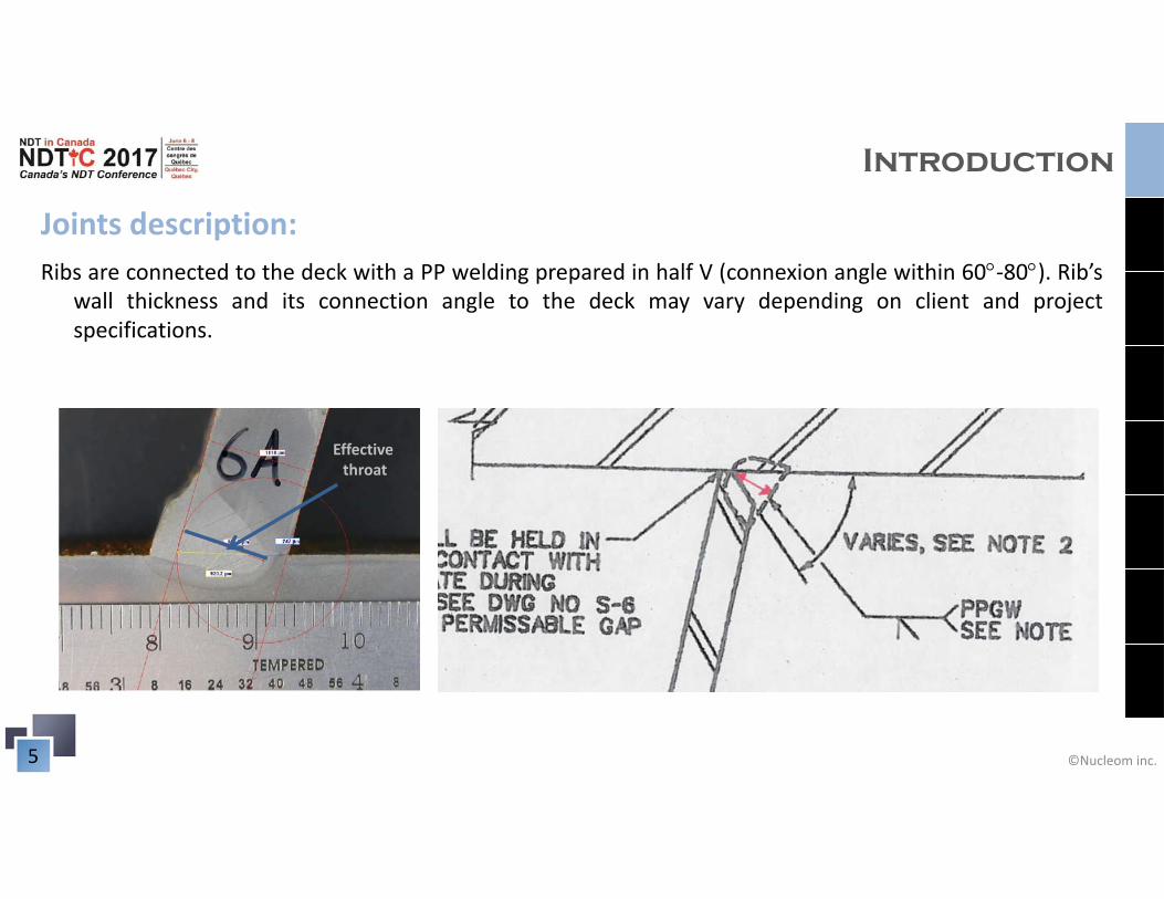
Joints description:Ribs are connected to the deck with a PP welding prepared in half V (connexion angle within 60‐80). Rib’s
wall thickness and its connection angle to the deck may vary depending on client and projectspecifications.
Effective throat

©Nucleom inc.6
Introduction
Joints description:Boxes are fabricated using 4 panels with two different thickness. Panels are connected
with half V PP L joints. Preparation is done on the thicker panel.
©Nucleom inc.7
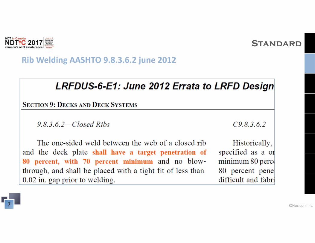
Rib Welding AASHTO 9.8.3.6.2 june 2012
Standard
©Nucleom inc.8
Standard
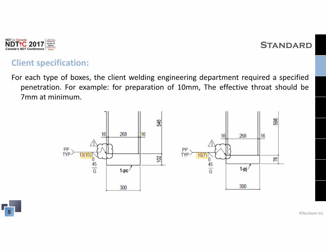
Client specification:For each type of boxes, the client welding engineering department required a specified
penetration. For example: for preparation of 10mm, The effective throat should be7mm at minimum.
©Nucleom inc.9
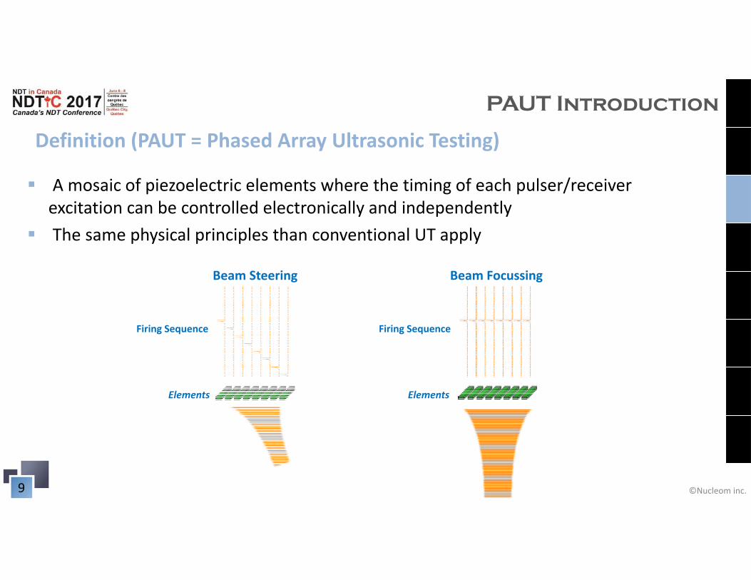
Definition (PAUT = Phased Array Ultrasonic Testing)
PAUT Introduction
A mosaic of piezoelectric elements where the timing of each pulser/receiver excitation can be controlled electronically and independently
The same physical principles than conventional UT apply
Firing Sequence
Elements
Beam Steering Beam Focussing
Firing Sequence
Elements
©Nucleom inc.10
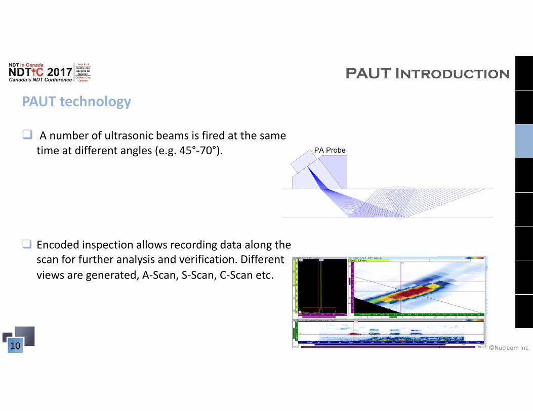
PAUT technology
PAUT Introduction
A number of ultrasonic beams is fired at the same time at different angles (e.g. 45°‐70°).
Encoded inspection allows recording data along the scan for further analysis and verification. Different views are generated, A‐Scan, S‐Scan, C‐Scan etc.
©Nucleom inc.11
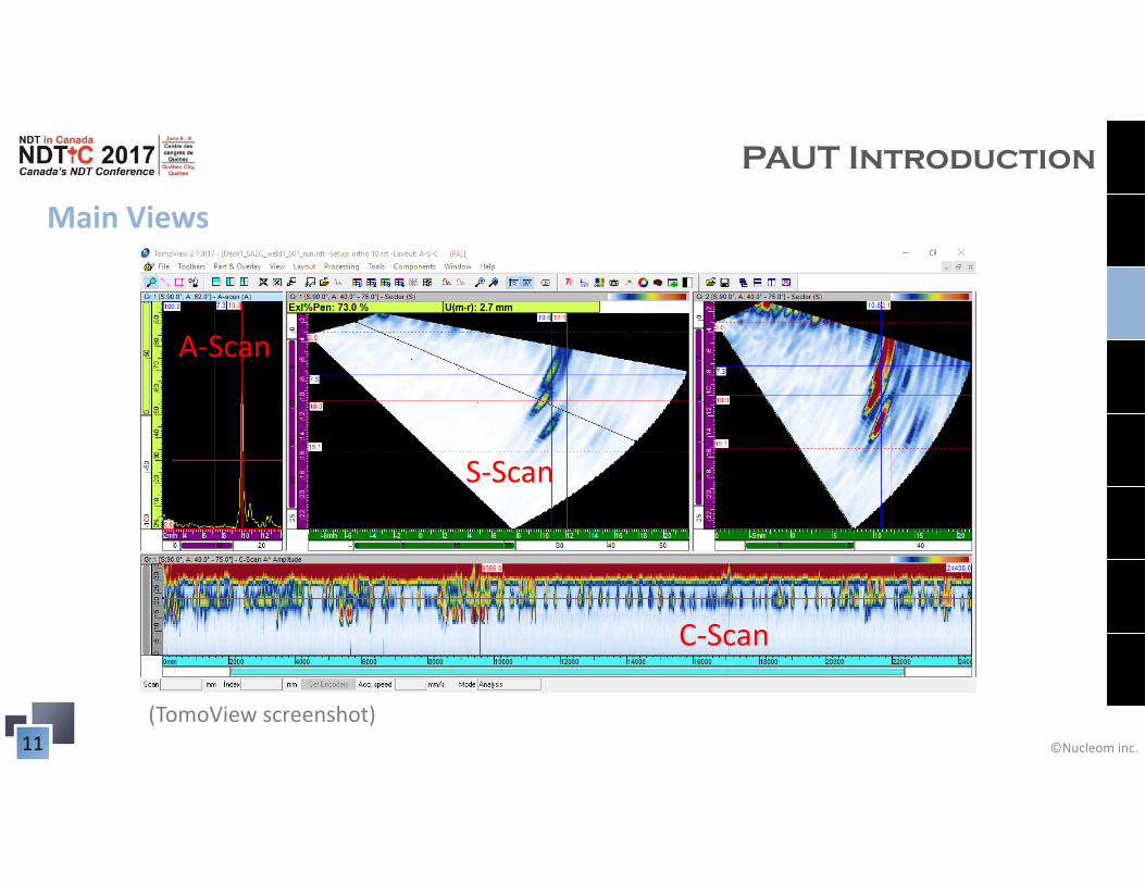
Main Views
PAUT Introduction
C‐Scan
S‐Scan
A‐Scan
(TomoView screenshot)
©Nucleom inc.12
Inspection methodology
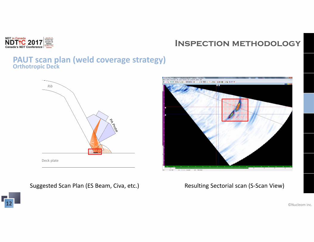
PAUT scan plan (weld coverage strategy)
Suggested Scan Plan (ES Beam, Civa, etc.) Resulting Sectorial scan (S‐Scan View)
Deck plate
Rib
Orthotropic Deck
©Nucleom inc.13
Inspection methodology
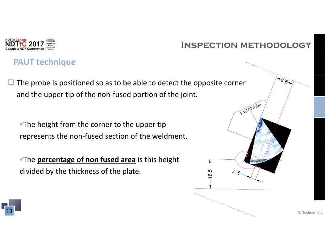
PAUT technique
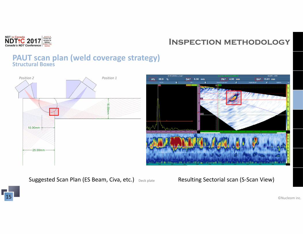
The probe is positioned so as to be able to detect the opposite corner and the upper tip of the non‐fused portion of the joint.
The height from the corner to the upper tip represents the non‐fused section of the weldment.
The percentage of non fused area is this height divided by the thickness of the plate.
©Nucleom inc.14
Inspection methodology
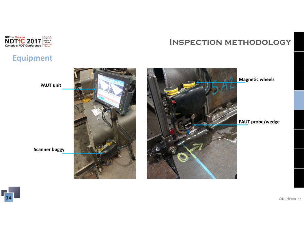
Equipment
PAUT unitMagnetic wheels
Scanner buggy
PAUT probe/wedge
©Nucleom inc.15
Inspection methodology
PAUT scan plan (weld coverage strategy)
Suggested Scan Plan (ES Beam, Civa, etc.) Resulting Sectorial scan (S‐Scan View)Deck plate
Position 1Position 2
Structural Boxes
©Nucleom inc.16
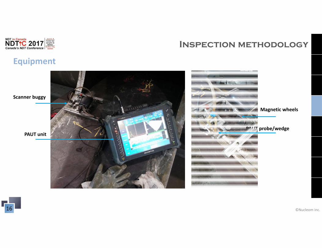
Inspection methodology
Equipment
PAUT unit
Magnetic wheels
Scanner buggy
PAUT probe/wedge
©Nucleom inc.17
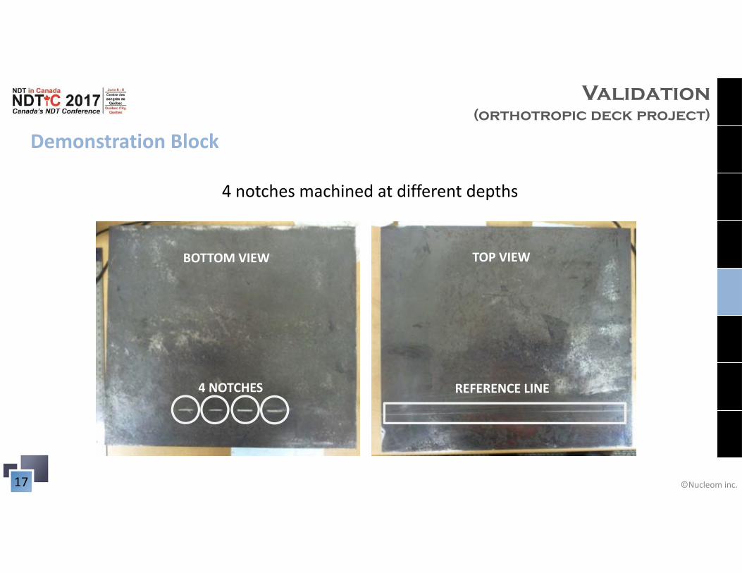
Validation (orthotropic deck project)
BOTTOM VIEW TOP VIEW
4 NOTCHES REFERENCE LINE
Demonstration Block
4 notches machined at different depths
©Nucleom inc.18
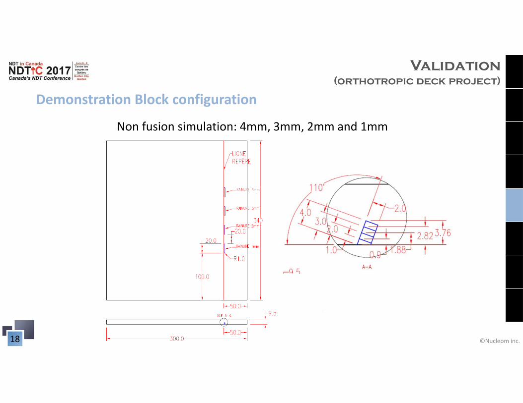
Demonstration Block configuration
Non fusion simulation: 4mm, 3mm, 2mm and 1mm
Validation (orthotropic deck project)
©Nucleom inc.19
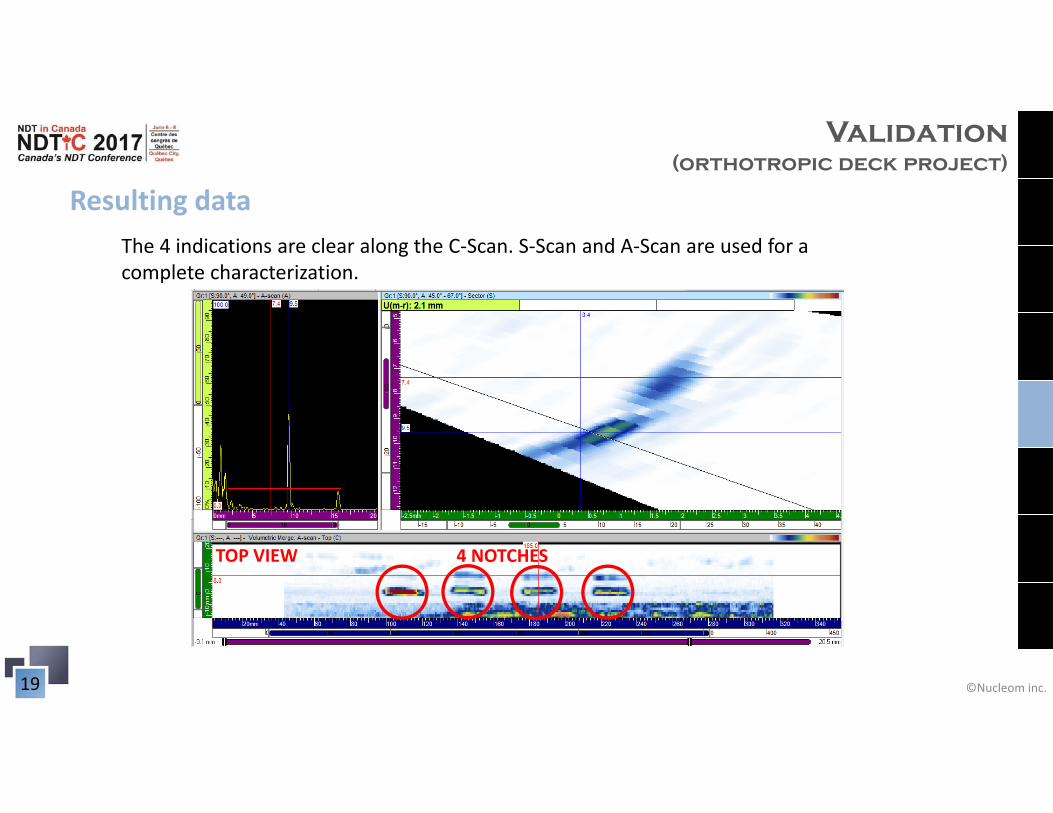
Resulting data
4 NOTCHESTOP VIEW
The 4 indications are clear along the C‐Scan. S‐Scan and A‐Scan are used for a complete characterization.
Validation (orthotropic deck project)
©Nucleom inc.20
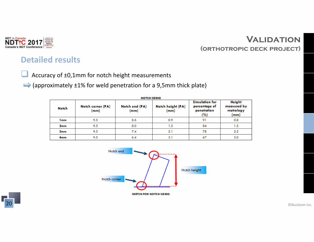
Detailed results
Accuracy of ±0,1mm for notch height measurements (approximately ±1% for weld penetration for a 9,5mm thick plate)
Validation (orthotropic deck project)
©Nucleom inc.21
TOP VIEW
4 NOTCHES REFERENCE LINE
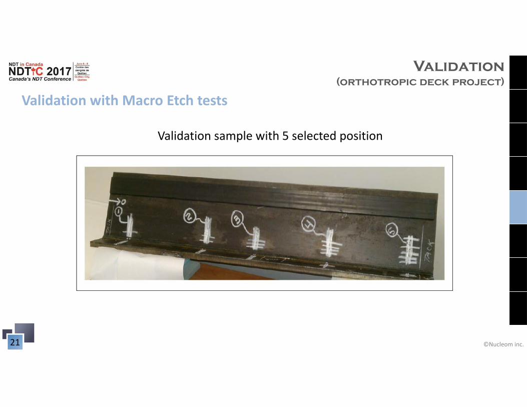
Validation with Macro Etch tests
Validation sample with 5 selected position
Validation (orthotropic deck project)
©Nucleom inc.22
TOP VIEW
4 NOTCHES REFERENCE LINE
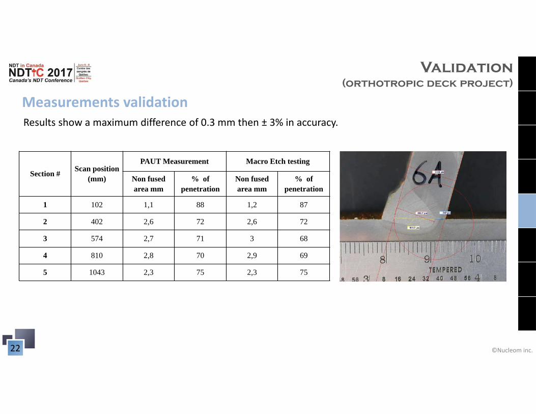
Measurements validation
Section # Scan position (mm)
PAUT Measurement Macro Etch testing
Non fused area mm
% of penetration
Non fused area mm
% of penetration
1 102 1,1 88 1,2 87
2 402 2,6 72 2,6 72
3 574 2,7 71 3 68
4 810 2,8 70 2,9 69
5 1043 2,3 75 2,3 75
Results show a maximum difference of 0.3 mm then ± 3% in accuracy.
Validation (orthotropic deck project)
©Nucleom inc.23
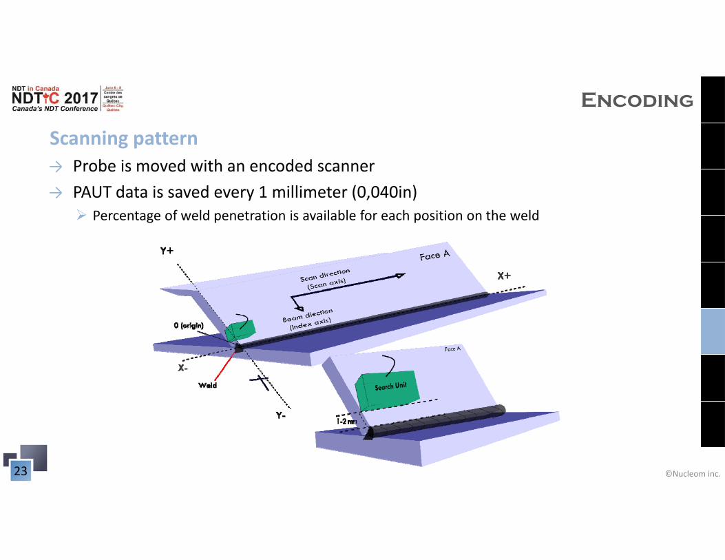
Scanning pattern
Encoding
→ Probe is moved with an encoded scanner→ PAUT data is saved every 1 millimeter (0,040in)
Percentage of weld penetration is available for each position on the weld
©Nucleom inc.24
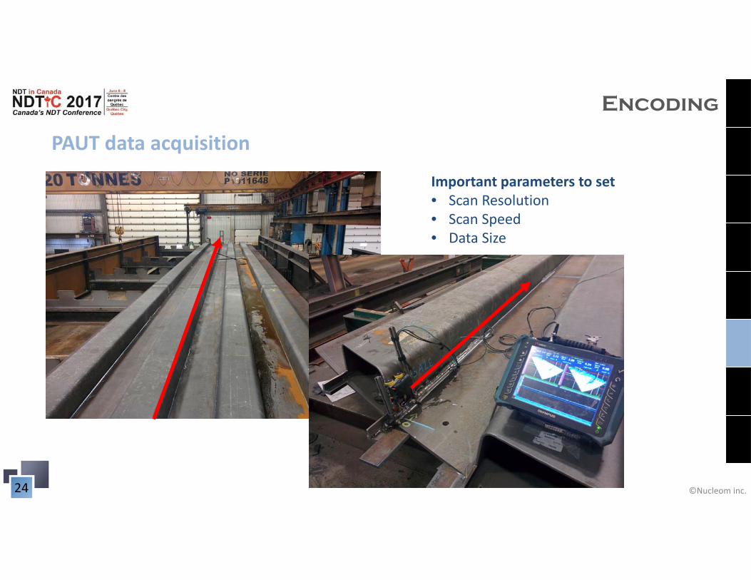
PAUT data acquisition
Encoding
Important parameters to set • Scan Resolution• Scan Speed• Data Size
©Nucleom inc.25
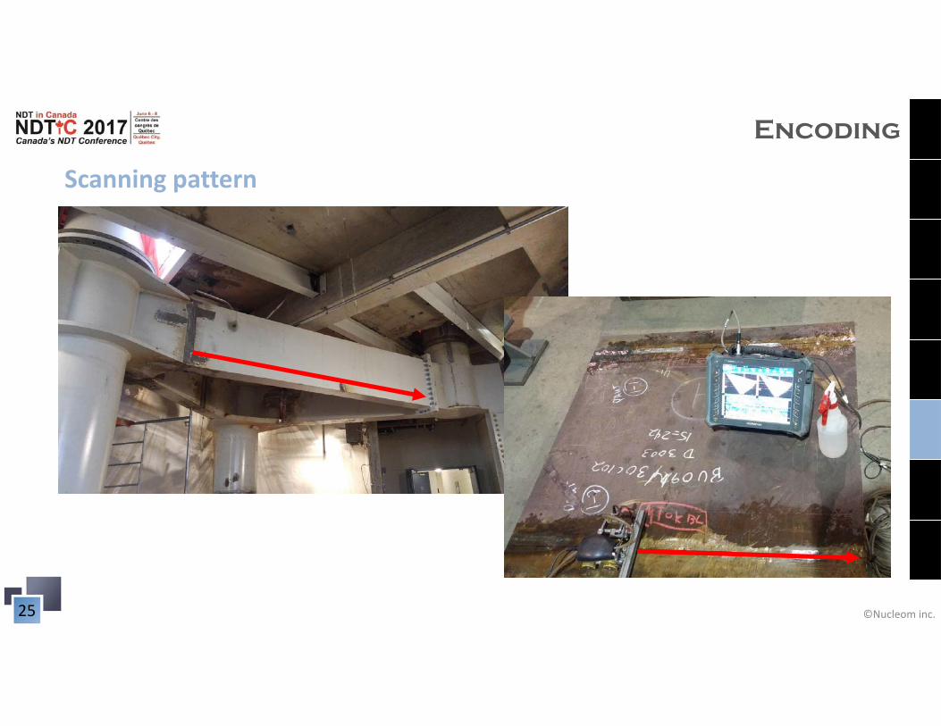
Scanning pattern
Encoding
©Nucleom inc.26
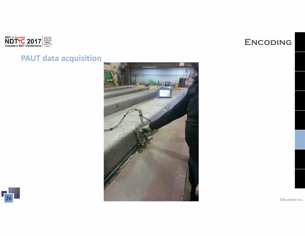
PAUT data acquisition
Encoding
©Nucleom inc.27
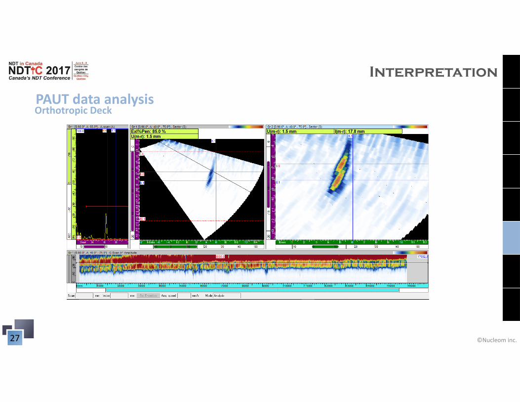
PAUT data analysis
Interpretation
Orthotropic Deck
©Nucleom inc.28
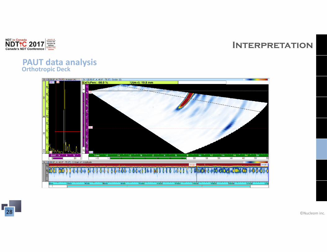
PAUT data analysis
Interpretation
Orthotropic Deck
©Nucleom inc.29
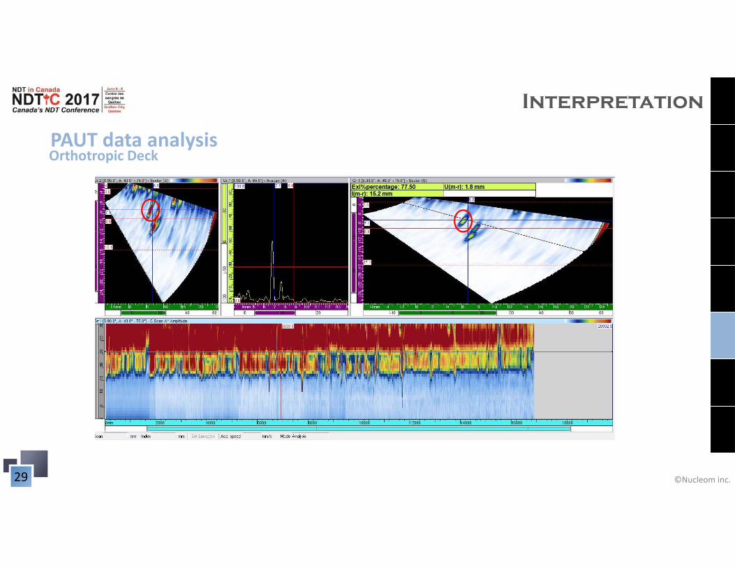
PAUT data analysis
Interpretation
Orthotropic Deck
©Nucleom inc.30
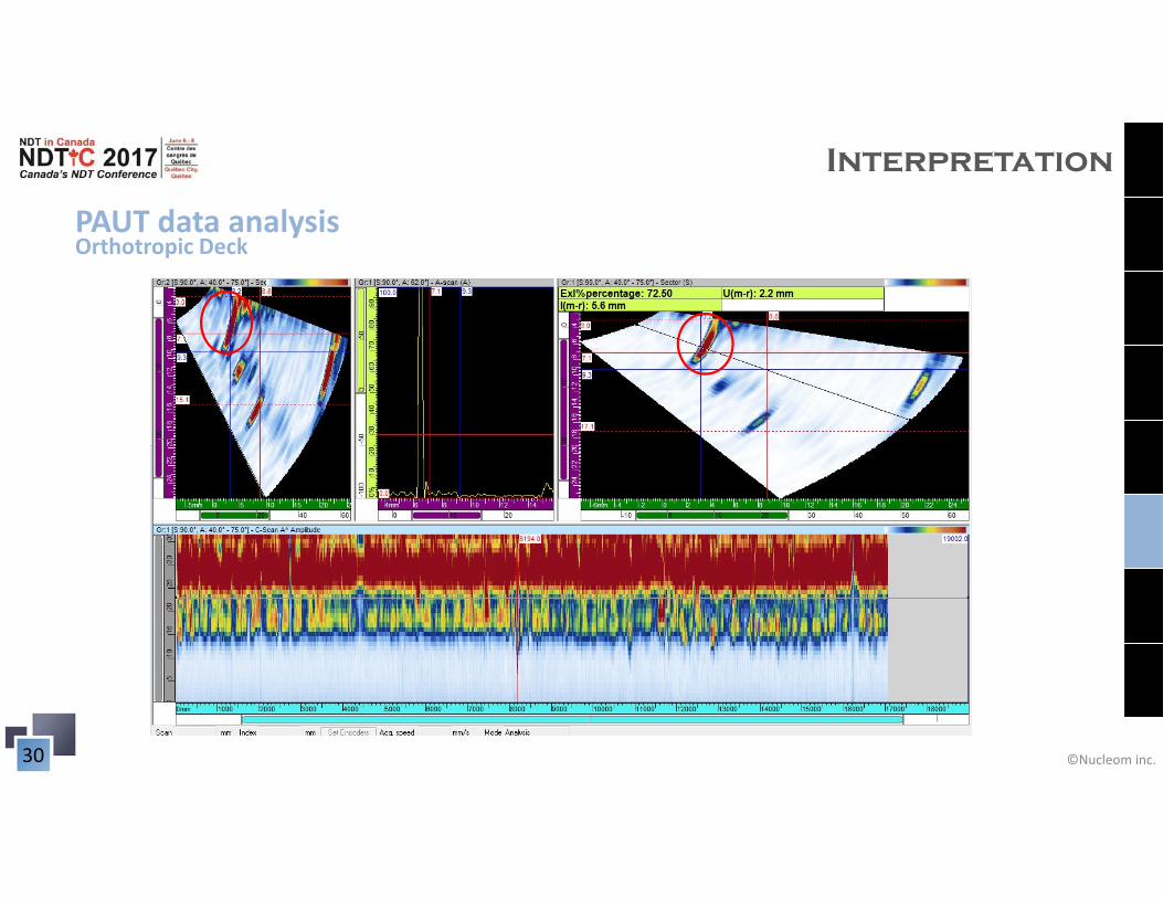
PAUT data analysis
Interpretation
Orthotropic Deck
©Nucleom inc.31
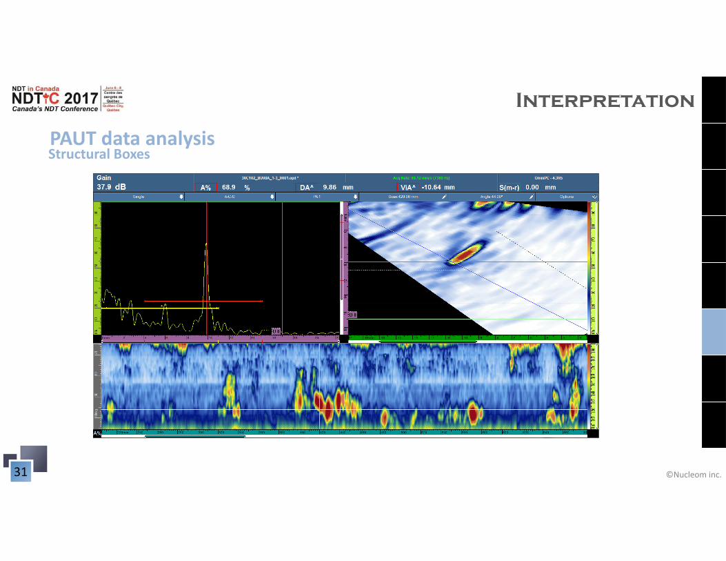
PAUT data analysis
Interpretation
Structural Boxes
©Nucleom inc.32
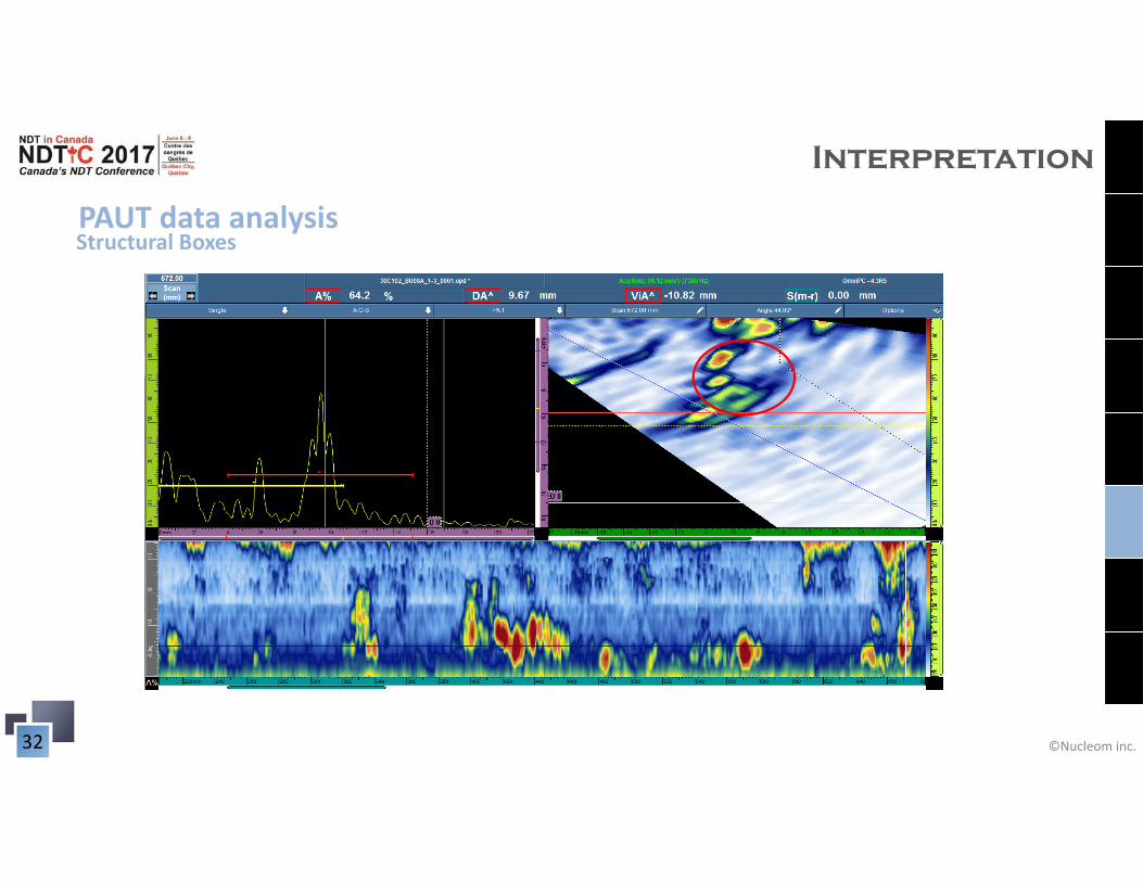
PAUT data analysis
Interpretation
Structural Boxes
©Nucleom inc.33
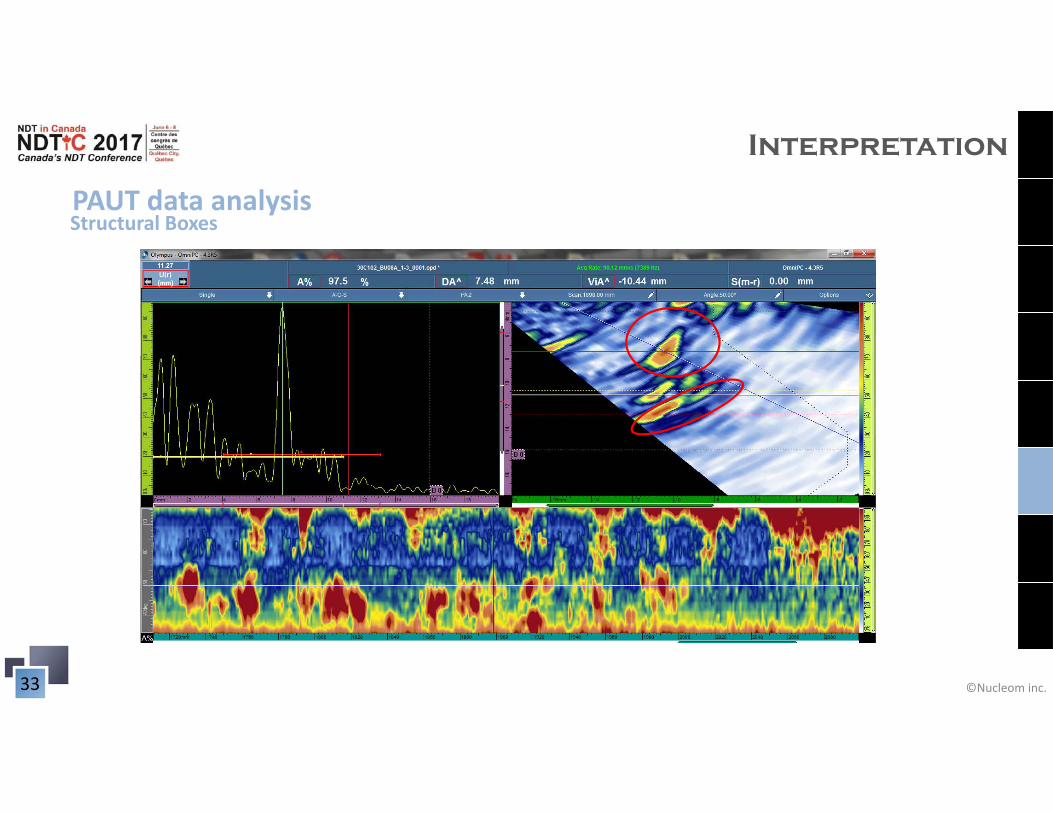
PAUT data analysis
Interpretation
Structural Boxes
©Nucleom inc.34
Inspection report example
Reporting
Orthotropic Deck
©Nucleom inc.35
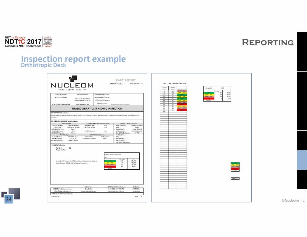
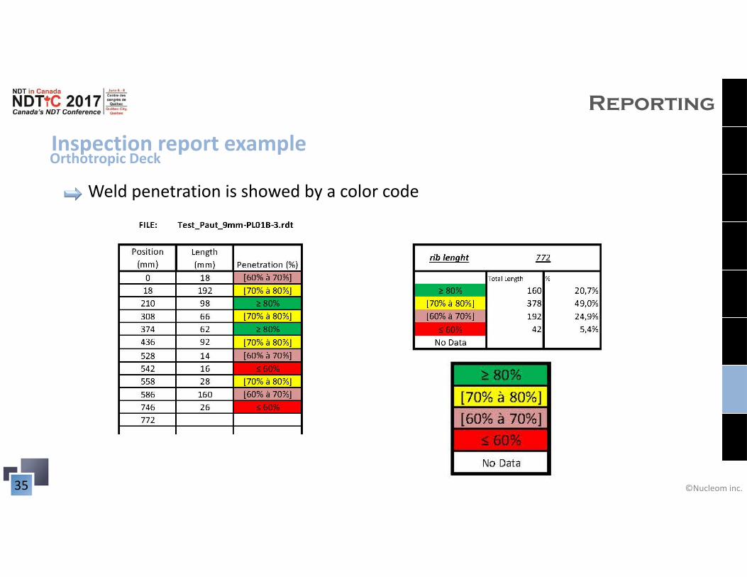
Inspection report example
Reporting
Weld penetration is showed by a color code
Orthotropic Deck
©Nucleom inc.36
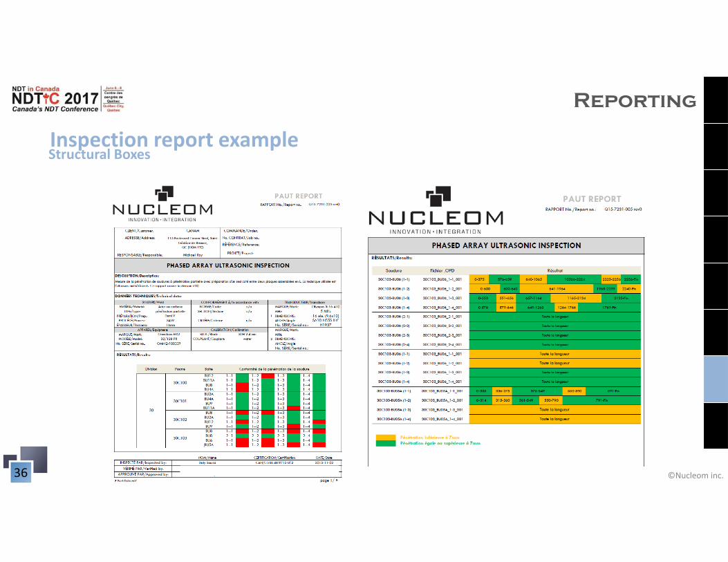
Inspection report example
Reporting
Structural Boxes
©Nucleom inc.37
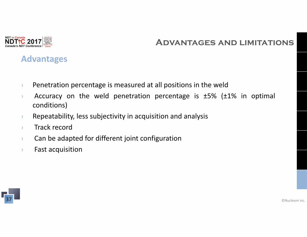
Advantages
› Penetration percentage is measured at all positions in the weld› Accuracy on the weld penetration percentage is ±5% (±1% in optimal
conditions)› Repeatability, less subjectivity in acquisition and analysis› Track record› Can be adapted for different joint configuration› Fast acquisition
Advantages and limitations
©Nucleom inc.38
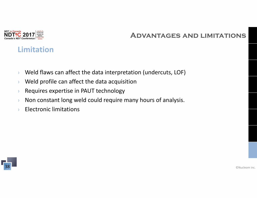
Limitation
› Weld flaws can affect the data interpretation (undercuts, LOF)› Weld profile can affect the data acquisition › Requires expertise in PAUT technology› Non constant long weld could require many hours of analysis.› Electronic limitations
Advantages and limitations
©Nucleom inc.39
Conclusion
PAUT (Phased Array Ultrasonic Testing) is an efficient technique to monitor weld
penetration for orthotropic bridges over the entire length of the weldment
The technique has been proven on 5 different projects (bridges and steel structures) in
collaboration with
©Nucleom inc.40
Conclusion
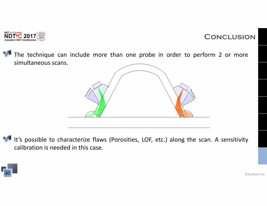
The technique can include more than one probe in order to perform 2 or moresimultaneous scans.
It’s possible to characterize flaws (Porosities, LOF, etc.) along the scan. A sensitivitycalibration is needed in this case.
©Nucleom inc.41
Special thanks to:
Francis Boudreault-Leclerc
Jérôme Boudreault-Leclerc
Éric Levesque

©Nucleom inc.42
Thank you, questions are welcome!