Embed Size (px)
Citation preview

1
X100 PAD2 Diagnosis System
Declaration1. This manual is designed for the usage of X100 PAD2, applying to X100 PAD2 smart automotive diagnosis platform.No part of this manual can be reproduced, stored in a retrieval system or transmitted, in any form or by any means (electronic, mechanical, photocopying, recording, or otherwise), without the prior written permission of Xtool. 2. Use the device only as described in this manual. The user will be responsible solely for the after-effects of violating the laws and regulations caused by using the product or its data information; in this case Xtool will not bear any legal responsibility.3. Xtool shall not be liable for any incidental or consequential damages or for any economic consequential damages arising from the accidents of individual users and the third parties, misuse or abuse of the device, unauthorized change or repair of the device, or the failure made by the user not to use the product according to the manual.4. All information, specifications and illustrations in this manual are based on the latest configurations and functions available at the time of printing. Xtool reserves the right to make changes at any time without notice.
5. is the registered trademark of SHENZHEN XTOOLTECH CO.,LTD.
6.In countries that the trademarks, service marks, domain names, logos and the name of the company are not registered, Xtool claims that it still reserves the ownership of the unregistered trademarks, service marks, domain names, logos and the company name. All other marks for the other products and the company’s name mentioned in the manual still belong to the original registered company.You may not use the trademarks, service marks, domain names, logos and company name of Xtool or other companies mentioned without written permission from the trademark holder.
7. Please visit www.xtool tech.com for more information on the X100 PAD2.8. Xtool reserves the right for the final interpretation of this manual content.
Xtool X100 PAD2 User Manual Instructions
Please read this user manual carefully before using the scanner. When reading the manual, please pay special attention to the words “Note”, “Caution” or “Warning”, read them carefully for appropriate operation.
Xtool X100 PAD2 Diagnosis System Main Unit Maintenance
Avoid shaking or dismantling the unit as it may damage the internal components. Do not use hard or sharp objects to touch the LCD screen; do not use excessive force; do not expose the screen to strong sunlight for a long period. Caution: keep it away from water, moisture, high temperature or very low temperature.If necessary, calibrate the screen before testing to ensure the accuracy of LCD performance. Keep the main unit away from strong magnetic fields.
1
X100 PAD2 Diagnosis System
Operation InstructionsFor safe operation please follow the instructions below: Keep the scanner away from heat or fumes when using it. If the vehicle battery contains acid, please keep your hands and skin or fire sources away from the battery during testing. Exhaust gas of vehicle contains harmful chemicals, please ensure adequate ventilation. Do not touch the cooling system components or exhaust manifolds when engine is running due to the high temperatures reached. Make sure the car is securely parked, Neutral is selected or the selector is at P or N position to prevent the vehicle from moving when engine starts. Make sure the (DLC) diagnostic link connector is functioning properly before starting the test to avoid damage to the Diagnostic Computer. Do not switch off the power or unplug the connectors during testing, otherwise you may damage the ECU and/or the Diagnostic Computer.
1
X100 PAD2 Diagnosis System
ContentsCHAPTER Ⅰ About X100 PAD2
................................................................................................................................................................41. Appearance..................................................................................................................................4
1.1. Front View..........................................................................................................................41.2. Back View...........................................................................................................................4
2. Layout of X100 PAD2 Tablet..........................................................................................................52.1. Top View of X100 PAD2 Tablet............................................................................................52.2. Side View of X100 PAD2 Tablet...........................................................................................5
3. X100 PAD2 Technical Parameters.................................................................................................5CHAPTER Ⅱ How to Use X100 PAD2 ......................................................................................................6
1. X100 PAD2 Activation...................................................................................................................62. X100 PAD2 Main Interface and Functional Buttons Descriptions..................................................6
2.1. Main Interface....................................................................................................................62.2. Sub-menu and Functional Buttons ....................................................................................7 2.3. Toolbar Functional Buttons.................................................................................................8
3. Vehicle Connection Diagnosis.......................................................................................................83.1. Vehicle Connection Test......................................................................................................83.2. Precautions Before Use......................................................................................................9
4. Special function and Diagnosis.....................................................................................................94.1. Menu Options....................................................................................................................94.2. Test Functions...................................................................................................................114.3. Read ECU .........................................................................................................................134.4. Read DTCs.........................................................................................................................134.5. Clear DTCs........................................................................................................................144.6. Read Live Data..................................................................................................................14
5. Settings.......................................................................................................................................176. XCloud........................................................................................................................................187. Update........................................................................................................................................188. Report.........................................................................................................................................199. Remote.......................................................................................................................................21
CHAPTER Ⅲ Location of Diagnostic Link Connectors on Different Vehicle Models.............................221. Diagnostic Link Connectors Locations of Various Vehicle Models...............................................222. Location Diagram of Vehicle Diagnostic Link Connectors............................................................253. Diagnostic Link Connectors Terminal Definition and Communication Protocols.........................25

1
X100 PAD2 Diagnosis System
CHAPTER Ⅰ About X100 PAD21. Appearance1.1. Front View
1.2. Back View

1
X100 PAD2 Diagnosis System
2. Layout of X100 PAD2 Tablet 2.1. Top View of X100 PAD2 Tablet
① Charging port: Battery charging② DB15 Port: Supports wired connection with car by the cable③ USB Type C Port: Connect with PC for data transmission ④ Power Button: Power on or power off
2.2. Side View of X100 PAD2 Tablet
① Earphone jacket② TF Card Port③ Mini HDMI Port
3. X100 PAD2 Technical ParametersOperating System: AndroidProcessor: Quad-core 1.6GHz ProcessorMemory: 1G RAM,16G FLASHDisplay: 8 inch IPS LCD with 1024x768p resolutionTP: 8 inch multi-point touch screenCamera: Rear camera, 5.0 Megapixel, AF with FlashlightSensors: Gravity Sensor, Ambient Light SensorAudio Input/Output: Microphone, Dual Speakers, 3-Band 3.5 mm stereo/standard headset jackPower and Battery: 4000mAh, 7.4V lithium-polymer batteryPower Voltage: 12VPower Consumption: 29.6WOperating Temperature: -20 to 50 (-4 to 12 )℃ ℉Humidity: <90%Dimension (L*W*H): 240*177*30mm
① ② ③ ④
① ② ③

1
X100 PAD2 Diagnosis System
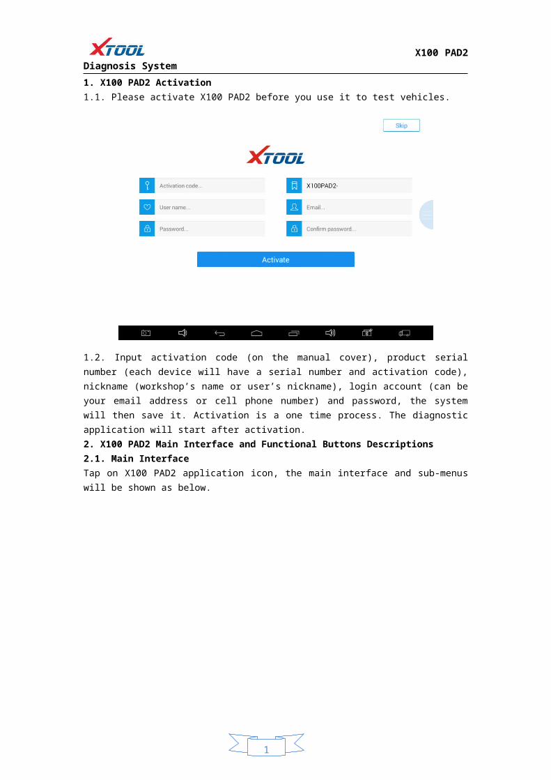
CHAPTER HowⅡ to Use the X100 PAD21. X100 PAD2 Activation1.1. Please activate X100 PAD2 before you use it to test vehicles.
1.2. Input activation code (on the manual cover), product serial number (each device will have a serial number and activation code), nickname (workshop’s name or user’s nickname), login account (can be your email address or cell phone number) and password, the system will then save it. Activation is a one time process. The diagnostic application will start after activation. 2. X100 PAD2 Main Interface and Functional Buttons Descriptions2.1. Main Interface Tap on X100 PAD2 application icon, the main interface and sub-menus will be shown as below.
1
X100 PAD2 Diagnosis System
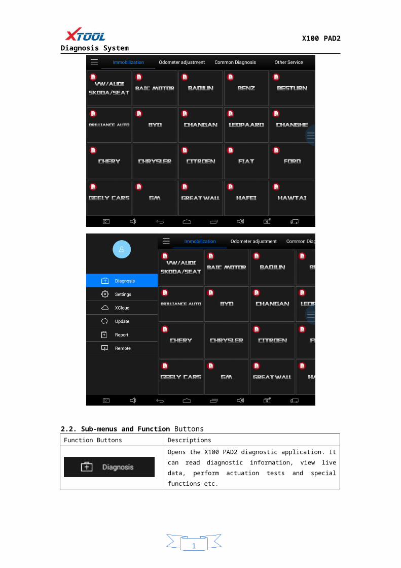
2.2. Sub-menus and Function ButtonsFunction Buttons Descriptions
Opens the X100 PAD2 diagnostic application. It can read diagnostic
information, view live data, perform actuation tests and special
functions etc.
By selecting “Setting”, users can access the language setting and
other system related settings.
Online Communication Platform for X100 PAD2 users.
(English version is coming soon)
Click UPDATE after X100 PAD2 is connected to internet, then you can
download the latest diagnostic software directly to X100 PAD2.
Users can view all the diagnostic reports and diagnostic data
generated in the diagnosis process.
Users can get remote help and support when needed.
1
X100 PAD2 Diagnosis System
2.3. Toolbar Function Buttons
Function Buttons Descriptions
Screen capture
Turn down the volume
Return to previous interface
Return to the main interface of Android System
Show (recently used) applications
Turn up the volume
Click here to return to the diagnostic interface
Click here to return to diagnostic vehicle models interface
3. Vehicle Connection Diagnosis3.1. Vehicle Connection Testa. Connect scanner and vehicle with cable in following order: b. Switch on the ignition and turn on X100 PAD2 tablet, then tap on X100 PAD2 application icon to test vehicles. (Shown as follows)
① X100 PAD2 Mainframe② Main Test Cable③ OBDII Connector④ Vehicle
① ② ③ ④

1
X100 PAD2 Diagnosis System
3.2. Precautions before Use3.2.1. The vehicle power supply has to meet the normal voltage limits DC 9-15V3.2.2. Users should check the position of the DLC port and ensure the OBDII 16pin connector and the DLC port are correctly aligned before attempting to connect.3.2.3. When taking some special functions tests, users are required to operate the device according to operating instructions. For vehicle, it has to strictly meet the requirements, for example, the conditions that some vehicle models need to be reached are as follows: engine temperature 80 /105 , turn off the loads (such as headlights, air-conditioner, etc.), put ℃ ℃ accelerator pedal in released position, etc.3.2.4. If users can not find the tested vehicle model or electronic control system in the X100 PAD2 test menu, they may need to update the software or consult Xtool technical service department.3.2.5. Please ensure that only official XTOOL cables and connectors are used to prevent damage to the unit.3.2.6. Before powering off the unit, please ensure that you cancel or complete the current task or function and return to the main interface, then power off.3.2.7. Do not excessive force to operate the touch screen.3.2.8. During long period of non-use, please disconnect the power and turn off the X100 PAD2 unit.
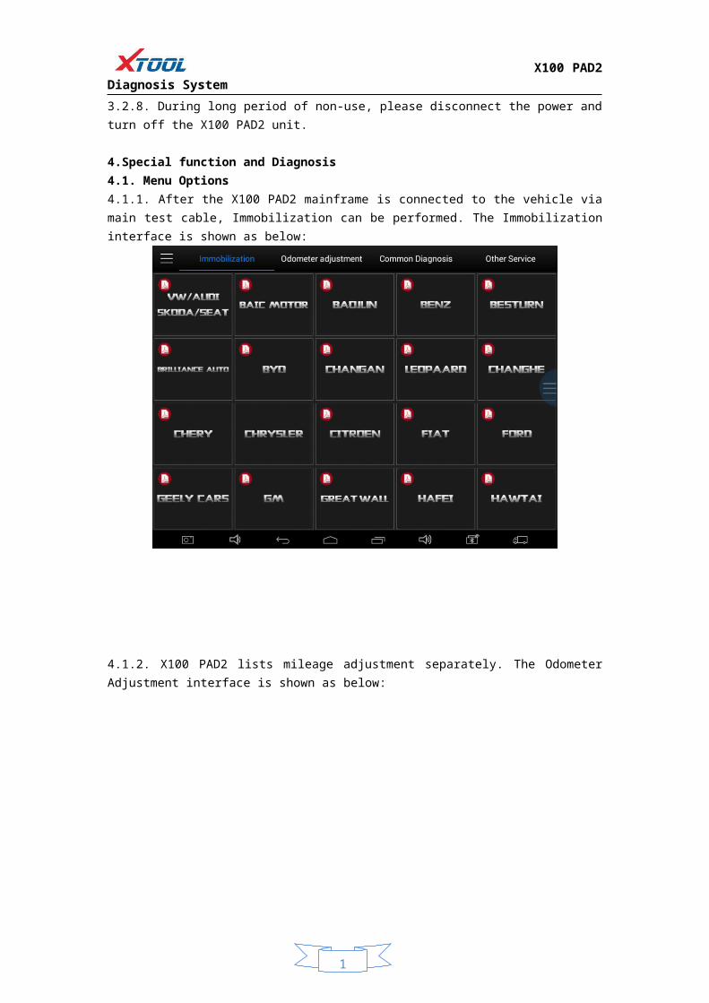
4.Special function and Diagnosis4.1. Menu Options4.1.1. After the X100 PAD2 mainframe is connected to the vehicle via main test cable, Immobilization can be performed. The Immobilization interface is shown as below:

1
X100 PAD2 Diagnosis System
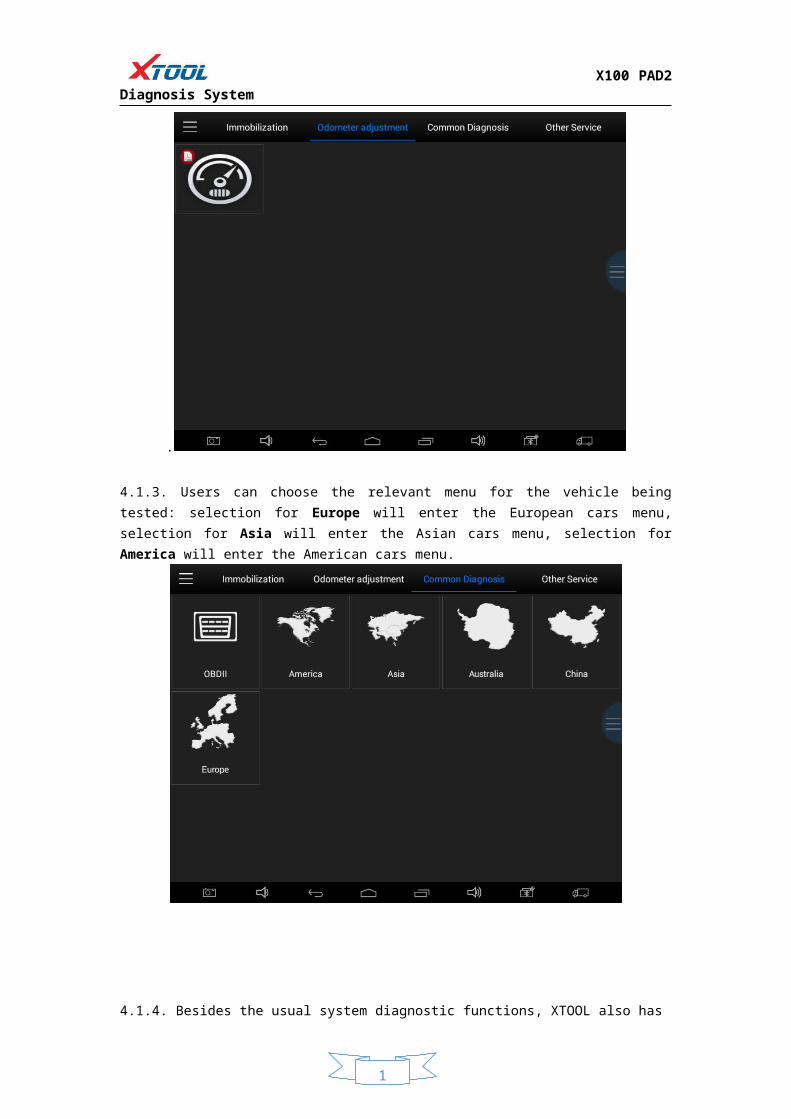
4.1.2. X100 PAD2 lists mileage adjustment separately. The Odometer Adjustment interface is shown as below:
.
4.1.3. Users can choose the relevant menu for the vehicle being tested: selection for Europe will enter the European cars menu, selection for Asia will enter the Asian cars menu, selection for America will enter the American cars menu.
1
X100 PAD2 Diagnosis System
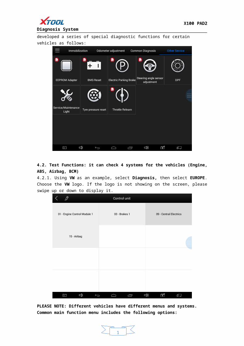
4.1.4. Besides the usual system diagnostic functions, XTOOL also has developed a series of special diagnostic functions for certain vehicles as follows:
4.2. Test Functions: it can check 4 systems for the vehicles (Engine, ABS, Airbag, BCM)4.2.1. Using VW as an example, select Diagnosis, then select EUROPE. Choose the VW logo. If the logo is not showing on the screen, please swipe up or down to display it.
PLEASE NOTE: Different vehicles have different menus and systems.Common main function menu includes the following options: Read ECU: This function is to read the ECU version information, which is the equivalent of “System Identification” or “System Information” in some electronic control systems.
1
X100 PAD2 Diagnosis System
This will allow you to read ECU related software and hardware versions, models and production date of diesel engine, part number, etc. Read DTCs: read the trouble codes that are stored in the ECU.Clear DTCs: clear current and historical trouble codes memory in ECU. The trouble codes can not be erased without eliminating the fault that the code relates to. TIP: Save or print the currently stored fault codes before clearing them to provide help in the case of an intermittent fault.Read Live Data: This will allow you to read the parameters of the system being interrogated, such as oil pressure, temperature, engine speed, fuel oil temperature, coolant temperature, intake air temperature, etc.
4.2.2. Toolbar function buttons descriptions
Function Buttons Descriptions
Return to previous interface
Print test data
Click to record the data, click again to send your feedback to XTOOL service center
After clicking the data record button the second time the data feedback page will appear as shown below, showing diagnostic software version, vehicle being tested, and the steps performed in the diagnostic process. Users can then enter the nature of the problem and any other relevant information and send the form to the Xtool engineering department.
1
X100 PAD2 Diagnosis System
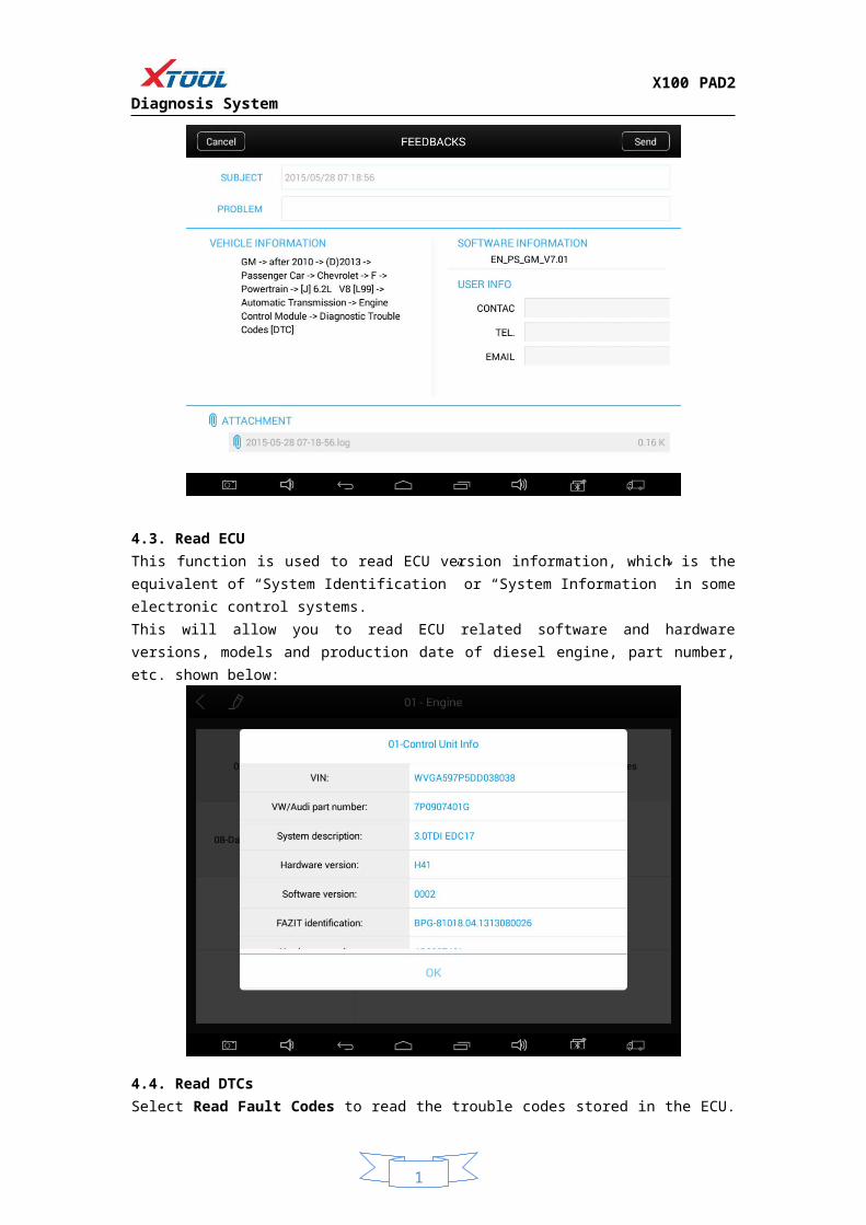
4.3. Read ECUThis function is used to read ECU version information, which is the equivalent of “System Identification” or “System Information” in some electronic control systems.This will allow you to read ECU related software and hardware versions, models and production date of diesel engine, part number, etc. shown below:
4.4. Read DTCsSelect Read Fault Codes to read the trouble codes stored in the ECU. The screen will show the trouble codes and their definition, shown below:
Tip: In the process of diagnosis, if the device shows “System is OK” or “No Trouble Code”, it indicates

1
X100 PAD2 Diagnosis System
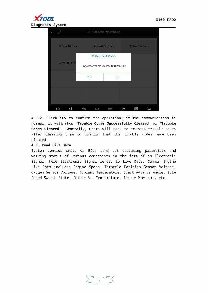
that the ECU has not detected a fault in any of the circuits that it monitors. If there is a fault which is not being recorded it may be that the fault is with a part of the system not under the control of ECU, such as a mechanical system fault. It is also possible that the signal of a system sensor may be incorrect but still within the ECUs stored limits, this can be verified in Live Data.4.5. Clear DTCs4.5.1. Return to the previous step, select Clear Fault Codes to clear the current and historical trouble codes memory in ECU. Performing this function will clear all the current and historical trouble codes. Please ensure that the trouble codes have been recorded before clearing, shown below:
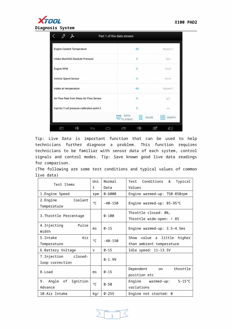
4.5.2. Click YES to confirm the operation, if the communication is normal, it will show “Trouble Codes Successfully Cleared” or “Trouble Codes Cleared”. Generally, users will need to re-read trouble codes after clearing them to confirm that the trouble codes have been cleared.4.6. Read Live DataSystem control units or ECUs send out operating parameters and working status of various components in the form of an Electronic Signal, here Electronic Signal refers to Live Data. Common Engine Live Data includes Engine Speed, Throttle Position Sensor Voltage, Oxygen Sensor Voltage, Coolant Temperature, Spark Advance Angle, Idle Speed Switch State, Intake Air Temperature, Intake Pressure, etc.
1
X100 PAD2 Diagnosis System
Tip: Live Data is important function that can be used to help technicians further diagnose a problem. This function requires technicians to be familiar with sensor data of each system, control signals and control modes. Tip: Save known good live data readings for comparison.(The following are some test conditions and typical values of common live data)
Test Items Unit Normal Data Test Conditions & Typical Values
1.Engine Speed rpm 0-6000 Engine warmed-up: 750-850rpm
2.Engine Coolant Temperature ℃ -40-150 Engine warmed-up: 85-95℃
3.Throttle Percentage 0-100Throttle closed: 0%,
Throttle wide-open: > 85
4.Injecting Pulse Width ms 0-15 Engine warmed-up: 3.5-4.5ms
5.Intake Air Temperature ℃ -40-150Show value a little higher than ambient
temperature
6.Battery Voltage v 0-15 Idle speed: 11-13.5V
7.Injection closed-loop correction 0-1.99
8.Load ms 0-15 Dependent on throttle position etc
9. Angle of Ignition Advance ℃ 0-50 Engine warmed-up: 5-15℃ variations
10.Air Intake kg/h 0-255 Engine not started: 0
11.Intake Pressure hpa 0-1013 Engine not started: 1013hpa
12. Idle-speed Adjustment Status 0-255
13.Oxygen Sensor mv 0-1000 Engine warmed-up: 50-960mv variations
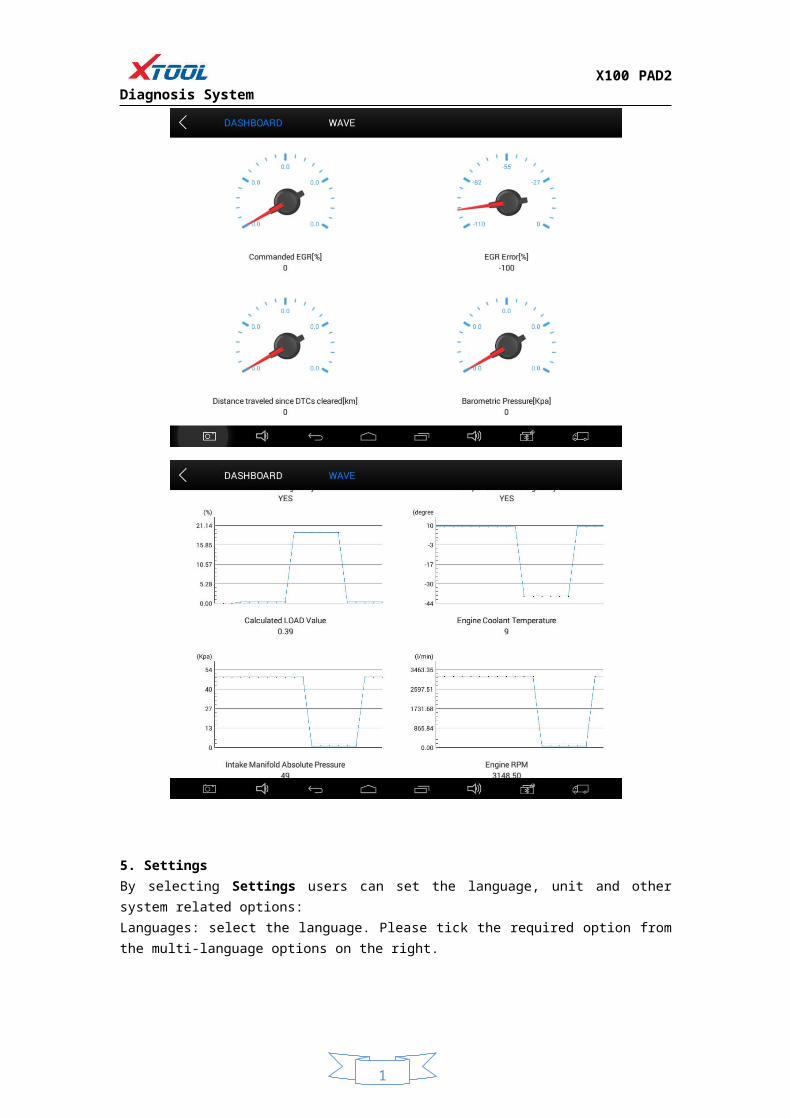
Display ModesThere are three modes with which to view Live Data, users can choose the optimum mode according to their own needs and different parameter types.Digital Mode: Displays parameters in numerical form.Dashboard Mode: Displays parameters in the form of simulated instrument graphics.Graph Mode: Displays parameters in graph form.

1
X100 PAD2 Diagnosis System
1
X100 PAD2 Diagnosis System
5. SettingsBy selecting Settings users can set the language, unit and other system related options:Languages: select the language. Please tick the required option from the multi-language options on the right.
1
X100 PAD2 Diagnosis System
Units: Select unit of measurement. Users can select Metric or British Unit.
6. XCloud (English version is coming soon)All the auto maintenance technicians who use our products can not only look up the maintenance information that we put on our cloud service platform conveniently, and combine the diagnosis result to query, and communicate with other Xtool users in our forum, but can also access various online databases of maintenance and diagnostic skills and vehicle maintenance plans.
7. UpdateX100 PAD2 updates directly via the Internet using WiFi or wired connection. To access the update application open the X100 PAD2 application and click UPDATE , shown below:

1
X100 PAD2 Diagnosis System
8. ReportReport is used for viewing and printing the saved files, such as Live Data, Trouble Codes or pictures generated in the process of diagnosis, users also can view a record of which cars have been previously tested. It includes three parts: PDF Files, Pictures and Data Playback.
8.1. PDF Files: 8.1.1. PDF files are the diagnostic reports of Live Data or Trouble Codes that have been saved during diagnosis. Entering PDF will allow you to view and print these reports.
1
X100 PAD2 Diagnosis System
8.1.2 Click PDF icon to generate PDF when you want to save the trouble code report
8.2. Pictures:Pictures are all the screen capture files saved in the diagnosis process.
8.3. Data Replay:With Data Playback you can play back recorded Live Data & freeze frame data.

1
X100 PAD2 Diagnosis System
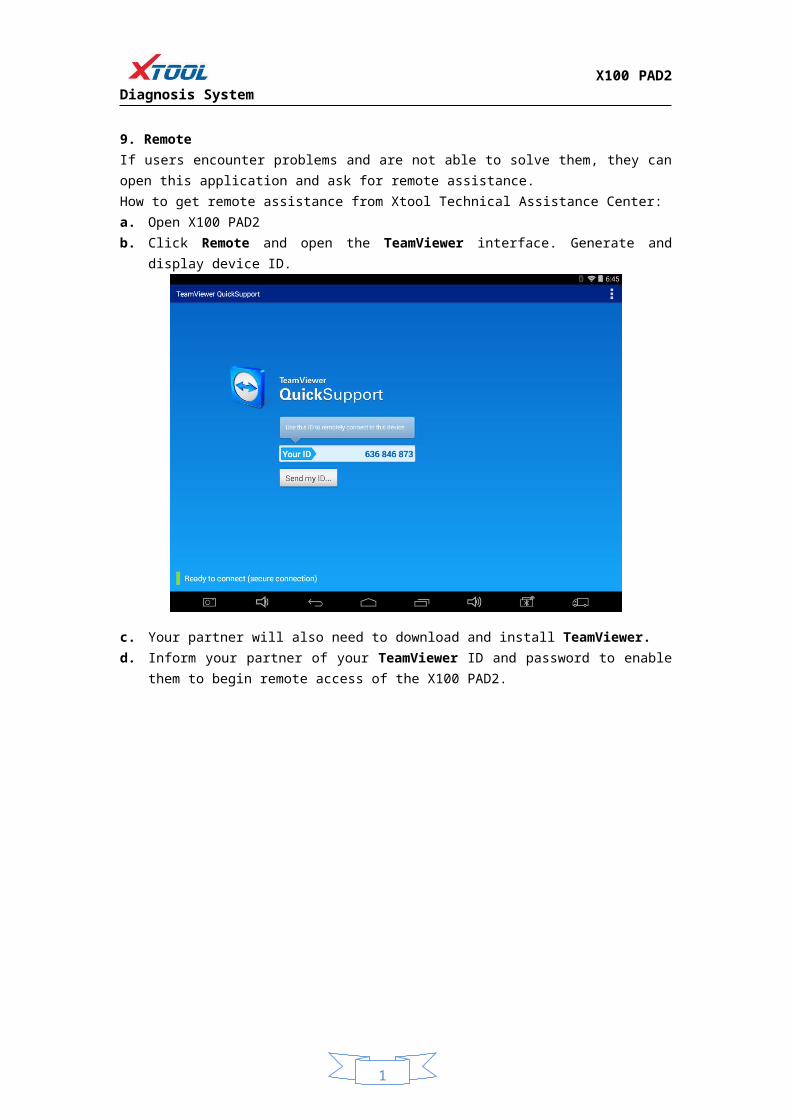
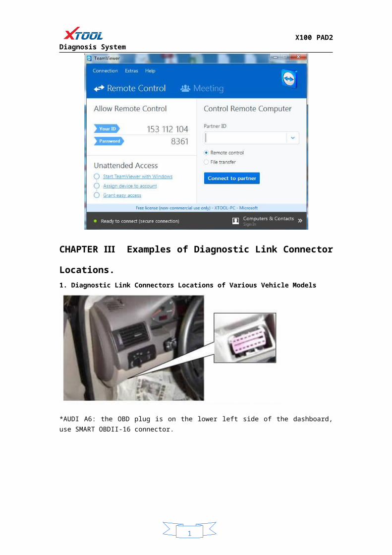
9. RemoteIf users encounter problems and are not able to solve them, they can open this application and ask for remote assistance.How to get remote assistance from Xtool Technical Assistance Center:a. Open X100 PAD2b. Click Remote and open the TeamViewer interface. Generate and display device ID.
c. Your partner will also need to download and install TeamViewer.

1
X100 PAD2 Diagnosis System
d. Inform your partner of your TeamViewer ID and password to enable them to begin remote access of the X100 PAD2.
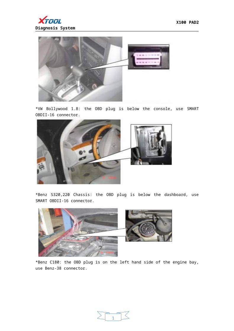
CHAPTER Ⅲ Examples of Diagnostic Link Connector Locations. 1. Diagnostic Link Connectors Locations of Various Vehicle Models
*AUDI A6: the OBD plug is on the lower left side of the dashboard, use SMART OBDII-16 connector.

1
X100 PAD2 Diagnosis System
*VW Bollywood 1.8: the OBD plug is below the console, use SMART OBDII-16 connector.
*Benz S320,220 Chassis: the OBD plug is below the dashboard, use SMART OBDII-16 connector.
*Benz C180: the OBD plug is on the left hand side of the engine bay, use Benz-38 connector.

1
X100 PAD2 Diagnosis System
*Benz 300SEL 140 chassis: the OBD plug is on the left hand side of the engine bay, use Benz-38 connector.
*GM Buick: the OBD plug is below the dashboard, use SMART OBDII-16 connector.
*GM Buick GL8 : the OBD plug is below the dashboard, use SMART OBDII-16 connector.
1
X100 PAD2 Diagnosis System
*VW POLO: the OBD plug is below the dashboard, use SMART OBDII-16 connector.
*BMW 735I: the OBD plug is in the right hands side of the engine bay, use BMW-20 connector.
*VW Passat B5: the OBD plug is behind the gearlever and beside the parking brake lever. Lift the cover to access it. Use SMART OBDII-16 connector.
2. Location Diagram of Vehicle Diagnostic Link Connectors
1
X100 PAD2 Diagnosis System
Location diagram of pick-up truck diagnostic link connectors:
Location diagram of utility vehicles diagnostic link connectors:
Link diagram of small car diagnostic link connectors:
NOTE: Each vehicle manufacturer may use additional pins to diagnose a variety of systems. Not every manufacturer uses the same standard. The function on a certain pin will vary from manufacturer to manufacturer. Verify with the manufacturer.
3. Diagnostic Link Connectors Terminal Definition and Communication Protocols3.1. Standard OBDII Diagnostic Link Connector:
Pin Definition (Reference material)
1
X100 PAD2 Diagnosis System
Various pin definitions as follows:1. Manufacturer definition2. SAE J1850 bus positive3. Manufacturer definition4. Bodywork site5. Signal site6. ISO 15765-4 defined CAN high7. ISO9141 and ISO14230 defined K line8. Manufacturer definition9. Manufacturer definition10. SAE J1850 bus negative11. Manufacturer definition12. Manufacturer definition13. ISO 15765-4 defined CAN low14. ISO9141 and ISO14230 defined L line15. Permanent positive voltage[1] 1, 3, 8, 9, 11, 12 and 13 are defined by manufacturer.[2] 2, 6, 7, 10, 14 and 15 are used for diagnostic communication. Unused definitions can be defined by manufacturers.


![DTC (Trouble Codes) - Crab Intakes Trouble Codes[1].pdfDTC (Trouble Codes) P0085 Exhaust Valve Control Solenoid Circuit Low P0086 Exhaust Valve Control Solenoid Circuit High P0087](https://img.dokumen.tips/doc/110x75/5a9fa9e97f8b9a62178d0493/pdfdtc-trouble-codes-crab-trouble-codes1pdfdtc-trouble-codes-p0085-exhaust.jpg)


![Trouble Codes OBDII[1]](https://img.dokumen.tips/doc/110x75/577ce7731a28abf103952cd6/trouble-codes-obdii1.jpg)
