Embed Size (px)
Citation preview
Welcome to the Session onWelcome to the Session on
HT Distribution NetworkHT Distribution Network
Learning Objective
By the end of this session you will be able to:
•Explain the HT distribution network breakdown maintenance - possible faults, identification and rectification
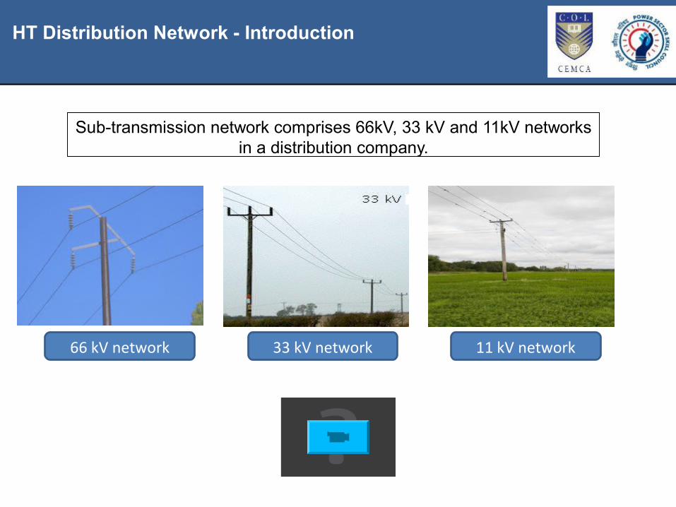
HT Distribution Network - Introduction
Sub-transmission network comprises 66kV, 33 kV and 11kV networks in a distribution company.
66 kV network 33 kV network 11 kV network

Causes for Faults in HT Distribution Network
The main causes for faults in HT distribution network are:•Over current•Over voltage•External agency•Accident•Natural disasters •And so on
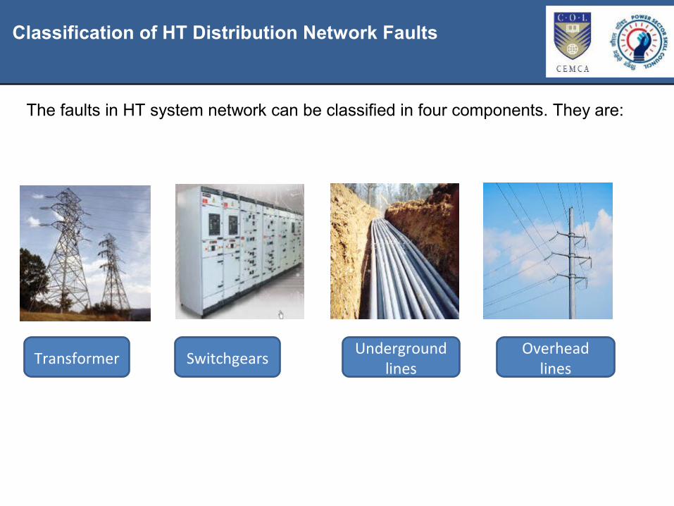
Classification of HT Distribution Network Faults
The faults in HT system network can be classified in four components. They are:
Transformer Switchgears Underground lines
Overhead lines
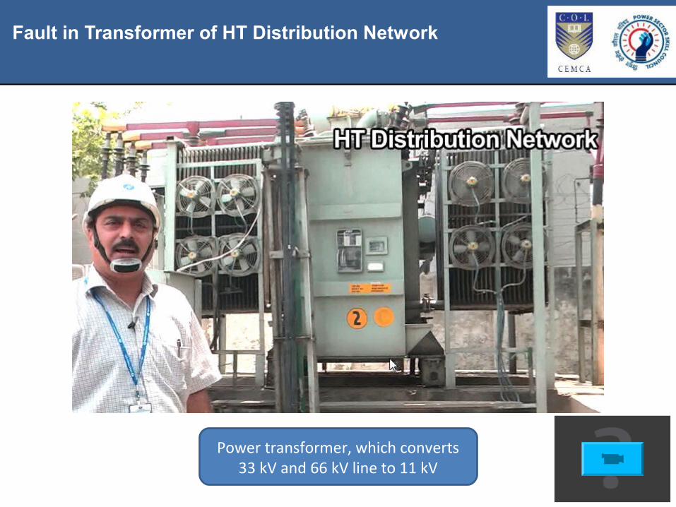
Fault in Transformer of HT Distribution Network
Power transformer, which converts 33 kV and 66 kV line to 11 kV

Fault in Transformer of HT Distribution Network
11 kV, 250 KVA distribution transformer
Components and accessories of a transformer

Fault in Transformer of HT Distribution Network
Tree has fallen on plinth mount transformer
Cat is trapped on live wires and got electrocuted
Common breakdowns occur in transformers

Fault in Transformer of HT Distribution Network
Damaged HT bushings

Fault in Transformer of HT Distribution Network
Replacement of damaged HT bushings

Fault in Transformer of HT Distribution Network
Oil leakage from valve

Fault in Transformer of HT Distribution Network
Examples of leakage from valve before and after

Fault in Transformer of HT Distribution Network
Leakage from tap changer before and after

Fault in Transformer of HT Distribution Network
Oil leakage cannot be stopped by M-Seal.

Fault in Transformer of HT Distribution Network
Usage of gaskets to plug the oil leakage

Fault in Transformer of HT Distribution Network
Replacement of gasket at LT bushing
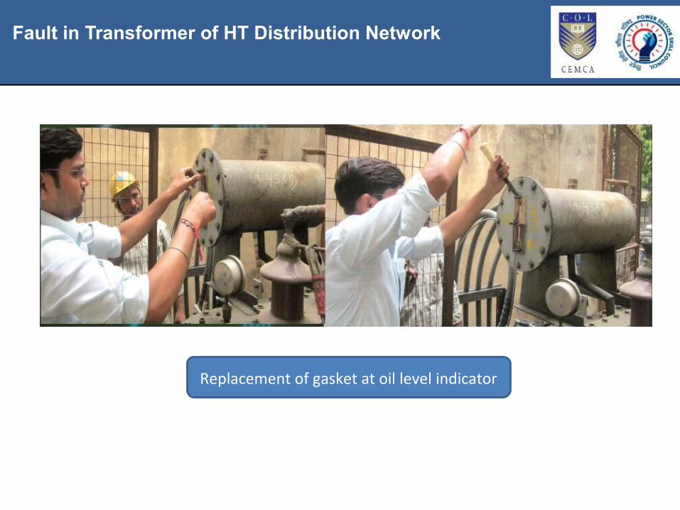
Fault in Transformer of HT Distribution Network
Replacement of gasket at oil level indicator
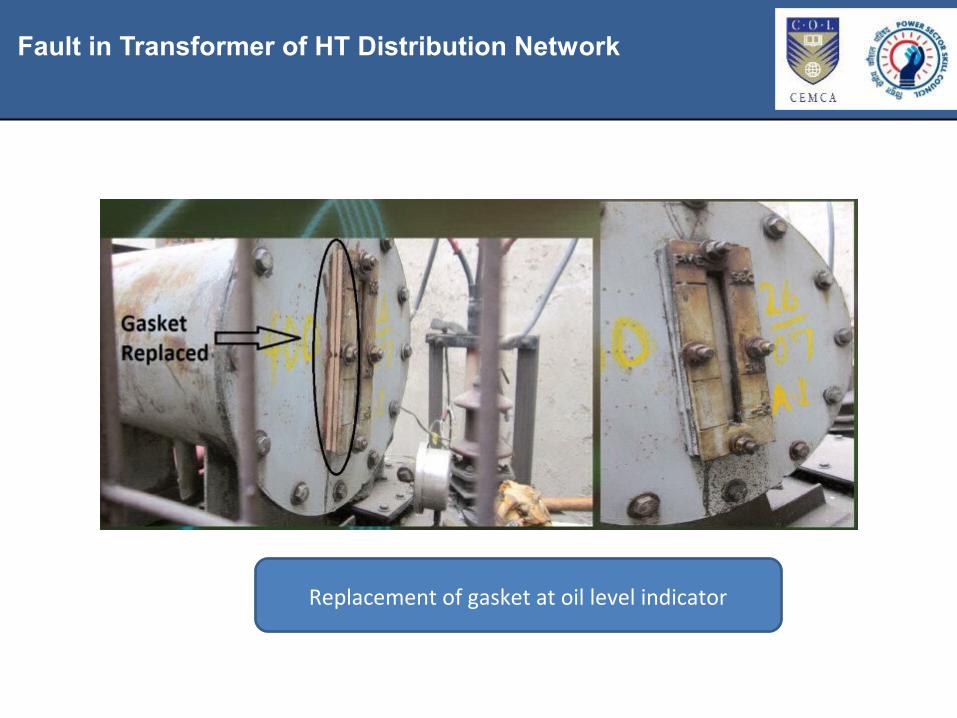
Fault in Transformer of HT Distribution Network
Replacement of gasket at oil level indicator
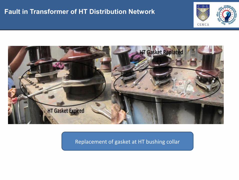
Fault in Transformer of HT Distribution Network
Replacement of gasket at HT bushing collar

Identification of Defects in Transformers and Their Remedies
Fault identified on HV bushing
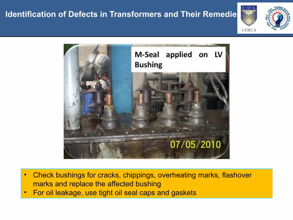
Identification of Defects in Transformers and Their Remedies
• Check bushings for cracks, chippings, overheating marks, flashover marks and replace the affected bushing
• For oil leakage, use tight oil seal caps and gaskets
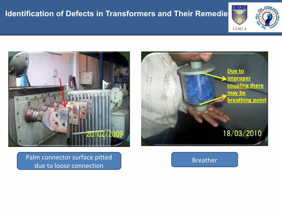
Identification of Defects in Transformers and Their Remedies
Palm connector surface pitted due to loose connection
Breather
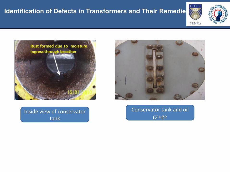
Identification of Defects in Transformers and Their Remedies
Inside view of conservator tank
Conservator tank and oil gauge

Identification of Defects in Transformers and Their Remedies
Explosion Vent Diaphragm IR value test with insulation tester
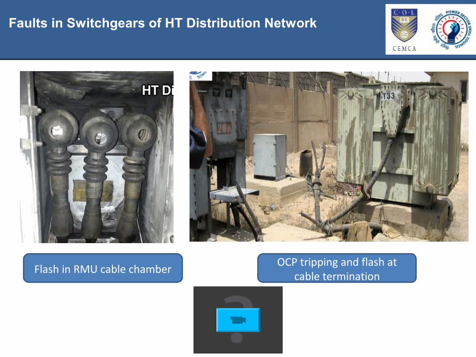
Faults in Switchgears of HT Distribution Network
Flash in RMU cable chamber OCP tripping and flash at cable termination

Types of Faults in Yard, Switchgear and Their Maintenance
Healthy condition of RMU

Types of Faults in Yard, Switchgear and Their Maintenance
Hotspot at palmtop conductor’s bus bar

Types of Faults in Yard, Switchgear and Their Maintenance
Hotspot at circuit breaker connection
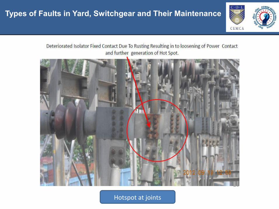
Types of Faults in Yard, Switchgear and Their Maintenance
Hotspot at joints
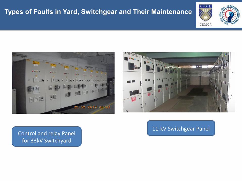
Types of Faults in Yard, Switchgear and Their Maintenance
Control and relay Panel for 33kV Switchyard
11-kV Switchgear Panel

Breakdowns Due to Natural Disasters
33 kV Circuit Breaker 11-kV Vacuum Circuit Breaker
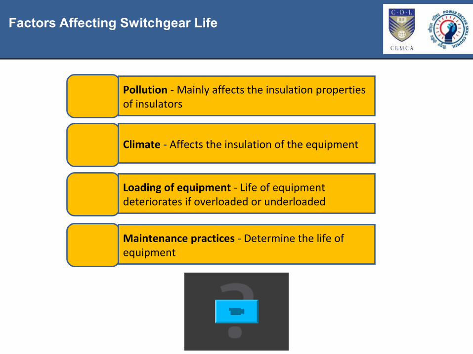
Factors Affecting Switchgear Life
Pollution - Mainly affects the insulation properties of insulators
Climate - Affects the insulation of the equipment
Loading of equipment - Life of equipment deteriorates if overloaded or underloaded
Maintenance practices - Determine the life of equipment

Thermal Imaging
• A thermal imaging camera is used• Detects the changes in heat in the
area to which they are pointed• An essential tool for preventative
maintenance• The cost for replacing the breaker at
this point will be small

Switchgears Installed in 11kV Sub-Station
Ring Main Unit (RMU)
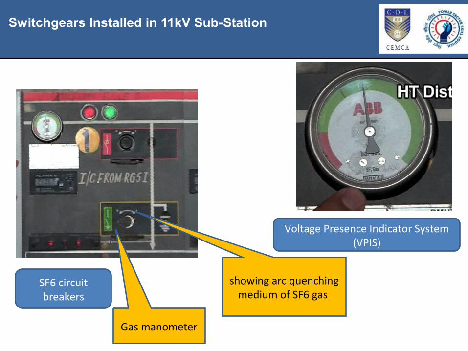
Switchgears Installed in 11kV Sub-Station
SF6 circuit breakers
Gas manometer
showing arc quenching medium of SF6 gas
Voltage Presence Indicator System (VPIS)

Faults in Cables of HT Distribution Network
Faults in Cables
Cable faults have become very common as many civic agencies work for development projects.
Excavation is an integral part of water and sewage lines, optic fibre, communication and gas pipeline works.
These agencies damage our cables during digging activities.
We need to get them repaired within 12-18 hours.
Fault Locating Vans (FLC) pinpoint the exact location of fault in underground cable.
Straight-through faults are repaired by jointing cables through straight through joint boxes.
The technicians are experts in repairing the transformers on the site.
In transformers, problems such as dissolved gas analysis (DGA) are handled by in-house staff.

Underground Cable Faults and Rectification
Fault locating van Instrument indicator Instrument that pin points the cable fault

Cable Testing, Fault Location and Recording Using Compact System
About Compact System
Compact System is one of the latest technologies of self-contained cable testing system.

Cable Testing, Fault Location and Recording Using Compact System
It is a small instrument, which is encased and is relatively a light computer aided system.
About Compact System

Cable Testing, Fault Location and Recording Using Compact System
• Exact pre-location, new method introduced i.e. Arm plus • Easy for testing, adjusting surge voltages and time
Compact System

Cable Testing, Fault Location and Recording Using Compact System
Cables
Cables of Compact System
There is now considerable preference for U/G cables over O/H lines.
In metropolitan cities, it is not feasible to have transmission and distribution with O/H lines due to non-availability of land for constructing O/H lines.
O/H lines mar the aesthetic value of a city’s skyline.
U/G system is preferred as it is unaffected by abnormal weather conditions, storms, tree falling, trees touching, snowfall and other objects.

Cable Testing, Fault Location and Recording Using Compact System
Causes for Cable Faults
• Mechanical damage• Damage of sheath or insulation - External agents• Sheath corrosion - due to chemical action• Vibration - due to heavy traffic on road• Thermal damage - increase in thermal resistance of soil, hot pipe• Operational problems• Cable deterioration - due to overloading• Joint deterioration - migration of semi-fluid compounds from joints, electrical
tracking along insulation owing to poor stress control• Terminal defects• Poor workmanship - joints• Manufacturing defects - cracked lead sheath
Cable Testing, Fault Location and Recording Using Compact System
Testing
IR Measurement
• IR measurement is done by using MEGGER• Phase to phase and phase to ground is tested using 5 kv MEGGER for 1 minute or
till reading stabilises• Minute IR value for healthy phase is 50 Mohm (11 kv), 100 Mohm (33 kv), 500
Mohm (66 kv)• U/G system is preferred as it is unaffected by abnormal weather conditions,
storms, tree falling, trees touching, snowfalls and foreign objects
LT Overhead Network
Testing
HVDC testing
• High Voltage DC testing (Pressure Testing) is done only after IR values are not found satisfactory
• Each phase is tested for 5 minutes with regard to ground and other phases grounded at 6.5 kv (11 kv cable),19.5 kv (33 kv), 38 kv (66 kv)
• The leakage current pattern is observed during the testing period (shown graphically in compact system)
• If the leakage current has a rising trend, the cable is faulty and if there is downward trend, cable may be healthy
• By testing, faulty phase(s) is detected

Instruments in the FLC Van
Pit for new cable joint
Damaged HT cable New HT cable joint
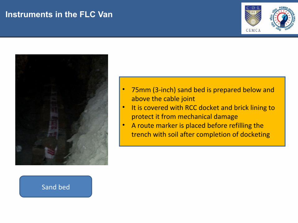
Instruments in the FLC Van
Sand bed
• 75mm (3-inch) sand bed is prepared below and above the cable joint
• It is covered with RCC docket and brick lining to protect it from mechanical damage
• A route marker is placed before refilling the trench with soil after completion of docketing
Instruments Used to Identify Faults in HT System
The common instruments used to identify faults in HT system are:
• MEGGER - To test insulation• High pot - To test voltage sustainability of cable• Thermo vision camera - To test hidden weak joints or links and• FLC van

Fault in ABC (Air Bunch Conductor) Cable
• This is due to corona discharge in 11 kV ABC cable• The cause for fault is that metallic screens of ABC cable are not grounded at the
end terminations• Induced voltage develops at the sheath of ABC. This causes short circuit and gets
damaged• It is mandatory to ground messenger wire with proper earthing

Replacement of Faulty HT Cable
Burnt AB cables Lineman replacing the burnt cable with the new one

Overhead System Faults and Their Rectification
Tree fallen on the HT lines
Damaged HT lines due to tree fall

Overhead System Faults and Their Rectification
Uprooted PCC pole carrying HT ABC line
Branch of tree damaged the HT line

Overhead System Faults and Their Rectification
Replacement of uprooted pole
Damaged HT lines in a flood-affected area
Overhead System Faults and Their Rectification
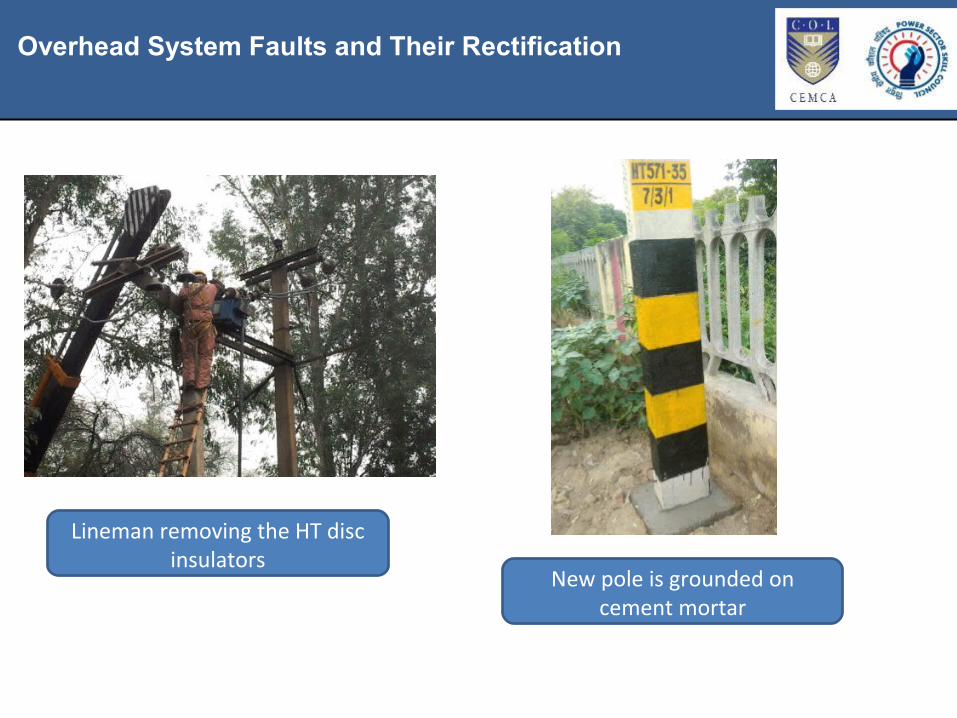
Lineman removing the HT disc insulators
New pole is grounded on cement mortar
Overhead System Faults and Their Rectification
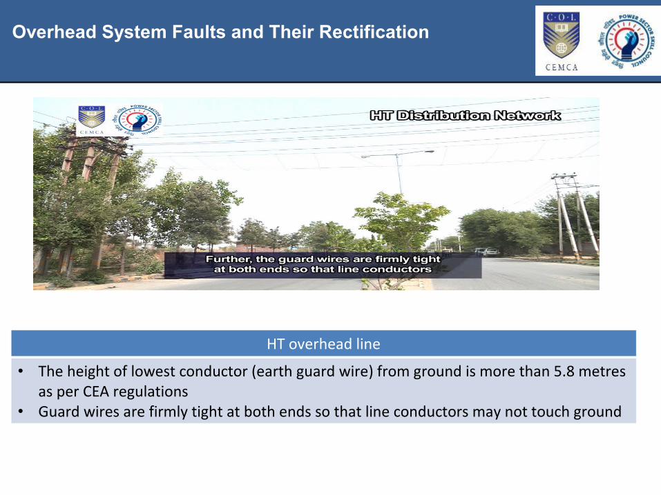
HT overhead line
• The height of lowest conductor (earth guard wire) from ground is more than 5.8 metres as per CEA regulations
• Guard wires are firmly tight at both ends so that line conductors may not touch ground

Key Learning Outcomes
• Sub-transmission network comprises 66kV, 33 kV and 11kV networks in a distribution company
• The faults in HT system network can be classified into transformer, switchgears, underground lines or overhead lines
• Factors affecting switchgear life are pollution, climate, loading of equipment and maintenance practices
• In thermal imaging, thermal cameras detect the changes in heat in the area to which they are pointed
• RMU or Ring Main Unit has 2 LBS or load break switches and 2 circuit breakers• Fault Locating Vans (FLC) pinpoint the exact location of fault in underground
cable• Compact System is one of the latest technologies of self-contained cable testing
system• IR measurement is done by using MEGGER