Embed Size (px)
Citation preview

Welcome to Lam Research

Slide - 2
Quick Change Cold Trap Project
Greg SextonStaff Mechanical EngineerNew Product Development
3/16/05

http://lamweb.lamrc.com/corpcomm/corp_marketing/Templates_Forms/standard_presentation.html
Slide - 3(v3)
Agenda
IntroductionProject DescriptionPrimary ConstraintsSecondary ConstraintsQ & A

http://lamweb.lamrc.com/corpcomm/corp_marketing/Templates_Forms/standard_presentation.html
Slide - 4(v3)
Introduction
What does Lam Research do?– Lam Research Corp. is a major semiconductor equipment manufacturer and the
world leader in semiconductor etching equipment
– More detailed information available at www.lamrc.com

http://lamweb.lamrc.com/corpcomm/corp_marketing/Templates_Forms/standard_presentation.html
Slide - 5(v3)
Introduction
** Critical Path always hinges upon the discovery/verification of critical process specifications. **
Manufacture Installation Test/VerifyPM Concept/Design
Redesign subsystem
Yes
No
Basic Feasibility Cycle:
Procure redesign
“Repeat until successful”
How are new ideas investigated by New Product Development?
Make available to Product Groups

http://lamweb.lamrc.com/corpcomm/corp_marketing/Templates_Forms/standard_presentation.html
Slide - 6(v3)
Quick Change Cold Trap Project
In the processing of a substrate, e.g., a semiconductor wafer, plasma is often employed. The wafer is processed in a series of steps, one of which is etching. During the etch process materials are selectively removed from the wafer to form features needed to form electrical components thereon.
Etching produces byproducts. Generally, volatile byproducts may be easily removed from the plasma chamber by the vacuum system, while non-volatile and low-volatile byproducts tend to be deposited on exposed surfaces within the plasma chamber which is undesirable.
For etching of non-volatile and low-volatile materials, assume that maintaining the main processing area at between 300-400C will keep the byproducts volatile and hence keep the area clean. For numerous reasons (use of elastomer seals etc.) the pumping system can not be maintained at these temperatures and there are components in the pumping system which are susceptible to the effects of these byproduct deposits. Valves, vacuum pumps and instrumentation can all fail prematurely when exposed to certain etch byproducts.

http://lamweb.lamrc.com/corpcomm/corp_marketing/Templates_Forms/standard_presentation.html
Slide - 7(v3)
Quick Change Cold Trap Project
Hence the problem. The byproduct stream exiting the main processing area, which is heated, enters the pumping system which is relatively cold (60C max) and deposits causing a loss of pumping system performance and premature failure of certain components.
Main Process Area
T=300-400C
Volatile Byproducts
Pumping Plenum
T=300-400C
Pumping System
T=60C Max
Volatile Byproducts
No Byproducts
Scrubber
Byproducts deposited in pumping system
Main Chamber unheated
http://lamweb.lamrc.com/corpcomm/corp_marketing/Templates_Forms/standard_presentation.html
Slide - 8(v3)
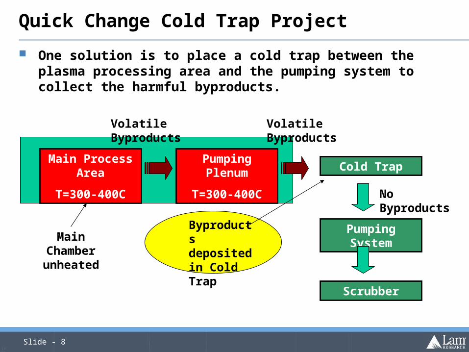
Quick Change Cold Trap Project
One solution is to place a cold trap between the plasma processing area and the pumping system to collect the harmful byproducts.
Main Process Area
T=300-400C
Pumping Plenum
T=300-400C
Pumping System
No Byproducts
Scrubber
Byproducts deposited in Cold Trap
Cold Trap
Volatile Byproducts Volatile Byproducts
Main Chamber unheated

http://lamweb.lamrc.com/corpcomm/corp_marketing/Templates_Forms/standard_presentation.html
Slide - 9(v3)
Primary Constraints The Cold Trap inlet must mate to a pumping plenum which is heated to
between 300-400C Cold Trap should capture 99% of byproducts Cold Trap can not back stream byproducts into the pumping plenum Conductance of Cold Trap should be maximized to minimize impact to pumping
efficiency Conductance from main chamber to Cold Trap to be less than 5% of the
conductance from the pumping plenum to the Cold Trap– Assume the pressures in the main chamber and pumping plenum are 300mTorr and
the pressure in the Cold Trap is 100mTorr Cold Trap should be serviceable in less than 3 hours without venting the main
chamber or cooling the main process area or pumping plenum Cold Trap materials must be appropriate for use with Cl2 Cold Trap must be easy to clean or have an inexpensive disposable liner
– Cost of disposable parts if used to be less than $500.00 Volume of Cold Trap and associated HW to be less than 3.75 cubic feet
– Cross Section, Inlet Port, Outlet Port, Connection Tube, Envelope
http://lamweb.lamrc.com/corpcomm/corp_marketing/Templates_Forms/standard_presentation.html
Slide - 10(v3)
Secondary Constraints Temperature of outside surfaces of Cold Trap Assembly not to exceed 60C Contamination Constraints
– Cold Trap can not contaminate the parts of the process module which see vacuum with oil, or other contamination
No Particle Adders– Process Module will be running in a Class 1 clean room
The less mechanisms the better – simple– Easy to set-up, service, and maintain
Highly reliable (Long term goal >10,000 hours MTBF)

Slide - 11
Q & A

http://lamweb.lamrc.com/corpcomm/corp_marketing/Templates_Forms/standard_presentation.html
Slide - 12(v3)
Envelope for Quick Change Cold Trap – 20.00”x27.00”x12.00” 17.00” above center line of inlet port, 10.00” below center line of inlet port, 10.00” to either side of the center line of the inlet port and 12.00” from face of inlet port
Center Line
of
Inlet Port