Embed Size (px)
Citation preview
machines
Article
Weight-Vibration Pareto Optimization of a TripleMass Flywheel for Heavy-Duty Truck Powertrains
Viktor Berbyuk
Department of Mechanics and Maritime Sciences, Chalmers University of Technology,SE-412 96 Gothenburg, Sweden; [email protected]
Received: 31 July 2020; Accepted: 28 August 2020; Published: 31 August 2020
Abstract: Enhanced efficiency of heavy-duty truck powertrains with constraints imposed on noise,vibration, and harshness requires novel solutions for torsion vibrations attenuation. In the paper,the weight-vibration Pareto optimization problem for a novel vibration absorber, a triple massflywheel, for application in heavy-duty truck powertrains is considered. Global sensitivity analysisand Pareto optimization method are used to design a novel vibration absorber. The optimizationmethod attempts to minimize oscillations of the torque at the transmission input shaft as well asto minimize total mass inertia of the absorber. It is shown that there exists a Pareto front betweenthe measure of the attenuation of oscillations of the torque and the total mass inertia of a triplemass flywheel. The optimized design parameters for the absorber are obtained that provide the bestattenuation of oscillations of the torque at the transmission input shaft for different mean values ofthe engine driving torque. The analysis shows real evidence of the feasibility of the application ofthis concept of vibration absorbers in heavy-duty truck powertrains. It is also shown that optimizeddesign parameters of a triple mass flywheel put this concept in a superior position in comparisonwith a dual mass flywheel.
Keywords: triple mass flywheel; heavy-duty truck powertrain; weight-vibration Pareto optimization;dual mass flywheel; torsional vibration absorbers
1. Introduction
The demand for higher efficiency of vehicle powertrain systems requires the development ofnovel drivetrain functional components. For instance, the heavy-duty truck industry struggles todevelop down-sized and down-speeded engines and higher cylinder pressure. This leads to moreexcitation coming to the transmission and requires advancing the available solutions for noise andvibration attenuation, making the design of efficient vibration absorbers for drivetrains of heavy-dutytrucks a big challenge.
One of the well-known vibration absorbers for drivetrains of ground vehicles is a dual massflywheel (DMF). The DMF was a subject of intensive research [1–8], and has been used in passengercar since the 1980s [9]. To increase the quality of vibration attenuation, the concept of a DMF beganto be modified by incorporating additional spring-mass components by combining with a so-calledcentrifugal pendulum vibration absorber, and additional absorbers with smooth and non-smoothnonlinearities [9–14]. Interesting research is ongoing on the development of controlled DMF for torsionalvibration attenuation in powertrain systems using controllable magnetorheological elastomeric springsand an appropriate controller design [15–17].
In heavy-duty truck drivetrains, the conventional single mass flywheel is still in use. However,increasing demand for a higher efficiency of truck powertrains requires novel solutions. The research isongoing both in academia as well as in industry to understand if a DMF as well as other multiple-massabsorbers are suitable for application in powertrains of heavy-duty trucks [18–24]. The idea of tuned
Machines 2020, 8, 50; doi:10.3390/machines8030050 www.mdpi.com/journal/machines
Machines 2020, 8, 50 2 of 13
mass damper, successfully used in a variety of engineering applications [25–29], was also appliedto modify a DMF performance. In recent work [19,21,22], DMFs with and without a tuned massdamper were studied for application to the powertrain of a heavy-duty truck. It was concluded that anoptimally design tuned mass damper could reduce the amplitude of oscillations of the torque at thetransmission input shaft more than corresponding conventional DMF. Using multiple-mass absorbers,for example, a DMF with a tuned mass damper, a decrease in the level of vibration in heavy-duty truckpowertrains is feasible. However, most probably, a larger installation space will be needed for novelabsorbers [19,22–24]. The latest calls for optimization of multiple-mass absorbers consider constraintson installation space, weight, reliability, cost, and so on. Different numerical methods are availableto optimize structure and performance of engineering systems; see, for example, [30–36]. A newmethod for optimizing the parameters of torsional vibration absorbers is presented in [32]. Topologyoptimization problems with specified eigenfrequencies and eigenmode shapes are considered in [34].Design optimization for composite structures operating in acoustic environments by using Newton’smethod is studied in [35].
In the present paper, both the requirement on the level of vibration attenuation and therestrictions on the installation space and weight are combined by considering the weight-vibrationPareto optimization (WV-PO) problem of torsional vibration absorbers for application in heavy-dutytruck powertrains. The bi-objective optimization problem is solved using the genetic algorithm—an optimization technique that has biological origins and works based on probabilistic searching [33].Two concepts of vibration absorbers are studied: a triplemass flywheel and a conventional DMF.A triple mass flywheel (TMF) is a novel concept of multiple-mass vibration absorbers with severaladvantages in comparison with a conventional DMF [37]. The TMF is described and the mathematicalmodel of a generic vehicle drivetrain equipped with this absorber is derived in Section 2. The resultsof the global sensitivity analysis of a TMF are presented in Section 3, showing the effect of variationof structural parameters on vibration attenuation, absorber’s total mass inertia, and friction betweenthe flywheels. The problem of weight-vibration Pareto optimal design of a TMF is formulated withfocus on their application in heavy-duty trucks powertrains and the solution is presented in Section 4.The obtained results are discussed in Section 5 in comparison with the corresponding results forweigh-vibration Pareto optimized DMF. The paper is finalized with conclusions and an outline offuture research.
2. Modelling
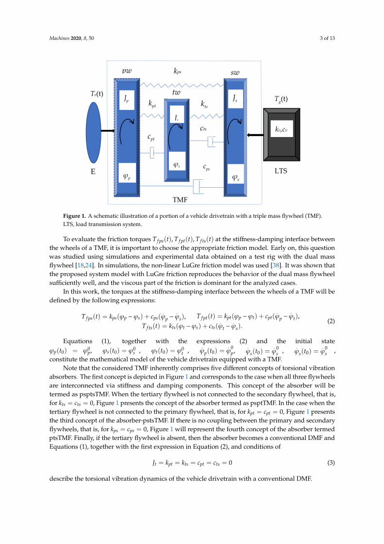
Figure 1 shows a schematic illustration of a portion of a vehicle drivetrain. The drivetrain includesan engine (E), a triple mass flywheel (TMF), and a load transmission system (LTS) that receives drivingpower from a TMF. The TMF comprises a primary wheel pw that receives rotational driving torquefrom engine, a tertiary wheel tw, and a secondary wheel sw that provides the driving power to thetransmission system.
In Figure 1, ϕp,ϕt,ϕs are absolute angles of rotation of the pw, the tw, and the sw, respectively;Jp, Jt, Js are axial moments of inertia of the pw, the tw, and the sw, respectively; kps, cps, kpt, cpt, kts, cts arecoefficients of torsional stiffness and torsional damping between the pw and the sw, the pw and the tw,and the tw and the sw, respectively. The crank mechanism inertia is not included in the Jp, and theinertia of the members located downstream the secondary flywheel is not included in the Js.
Using a free-body diagram, the equations of torsional vibration dynamics of the drivetrainequipped with a TMF are written as follows:
Jp..ϕp = Te(t) − T f ps(t) − T f pt(t), Js
..ϕs = T f ps(t) + T f ts(t) − Tg(t), Jt
..ϕt = T f pt(t) − T f ts(t). (1)
Here, in Equations (1) Te(t), Tg(t) are the engine driving torque and the torque at the transmissioninput shaft, respectively.
Machines 2020, 8, 50 3 of 13Machines 2020, 8, x FOR PEER REVIEW 3 of 13
Figure 1. A schematic illustration of a portion of a vehicle drivetrain with a triple mass flywheel (TMF). LTS, load transmission system.
In Figure 1, , ,p t sϕ ϕ ϕ are absolute angles of rotation of the pw, the tw, and the sw, respectively;
, ,p t sJ J J are axial moments of inertia of the pw, the tw, and the sw, respectively; , , , , ,ps ps pt pt ts tsk c k c k c are coefficients of torsional stiffness and torsional damping between the pw and the sw, the pw and the tw, and the tw and the sw, respectively. The crank mechanism inertia is not included in the pJ , and the inertia of the members located downstream the secondary flywheel is not included in the sJ .
Using a free-body diagram, the equations of torsional vibration dynamics of the drivetrain equipped with a TMF are written as follows:
( ) ( ) ( ), ( ) ( ) ( ), ( ) ( ).p p e fps fpt s s fps fts g t t fpt ftsJ T t T t T t J T t T t T t J T t T tϕ ϕ ϕ= − − = + − = − (1)
Here, in Equations (1) ( ), ( )e gT t T t are the engine driving torque and the torque at the transmission input shaft, respectively.
To evaluate the friction torques ( ), ( ), ( )fps fpt ftsT t T t T t at the stiffness-damping interface between the wheels of a TMF, it is important to choose the appropriate friction model. Early on, this question was studied using simulations and experimental data obtained on a test rig with the dual mass flywheel [18,24]. In simulations, the non-linear LuGre friction model was used [38]. It was shown that the proposed system model with LuGre friction reproduces the behavior of the dual mass flywheel sufficiently well, and the viscous part of the friction is dominant for the analyzed cases.
In this work, the torques at the stiffness-damping interface between the wheels of a TMF will be defined by the following expressions:
( ) ( ) ( ), ( ) ( ) ( ),( ) ( ) ( ).
fps ps p s ps p s fpt pt p t pt p t
fts ts t s ts t s
T t k c T t k cT t k cϕ ϕ ϕ ϕ ϕ ϕ ϕ ϕ
ϕ ϕ ϕ ϕ= − + − = − + −
= − + −
(2)
Equations (1), together with the expressions (2) and the initial state 0 0 0 0 0 0
0 0 0 0 0 0( ) , ( ) , ( ) , ( ) , ( ) , ( ) ,p p s s t t p p s s s st t t t t tϕ ϕ ϕ ϕ ϕ ϕ ϕ ϕ ϕ ϕ ϕ ϕ= = = = = = constitute the mathematical model of the vehicle drivetrain equipped with a TMF.
Note that the considered TMF inherently comprises five different concepts of torsional vibration absorbers. The first concept is depicted in Figure 1 and corresponds to the case when all three flywheels are interconnected via stiffness and damping components. This concept of the absorber
E
Te(t)
TMF
φp
Jp
Jt
φt
Tg(t)
kv,cv
cps
cts
LTS
Js
φs
kps
kpt
cpt
pw sw
tw kts
Figure 1. A schematic illustration of a portion of a vehicle drivetrain with a triple mass flywheel (TMF).LTS, load transmission system.
To evaluate the friction torques T f ps(t), T f pt(t), T f ts(t) at the stiffness-damping interface betweenthe wheels of a TMF, it is important to choose the appropriate friction model. Early on, this questionwas studied using simulations and experimental data obtained on a test rig with the dual massflywheel [18,24]. In simulations, the non-linear LuGre friction model was used [38]. It was shown thatthe proposed system model with LuGre friction reproduces the behavior of the dual mass flywheelsufficiently well, and the viscous part of the friction is dominant for the analyzed cases.
In this work, the torques at the stiffness-damping interface between the wheels of a TMF will bedefined by the following expressions:
T f ps(t) = kps(ϕp −ϕs) + cps(.ϕp −
.ϕs), T f pt(t) = kpt(ϕp −ϕt) + cpt(
.ϕp −
.ϕt),
T f ts(t) = kts(ϕt −ϕs) + cts(.ϕt −
.ϕs).
(2)
Equations (1), together with the expressions (2) and the initial stateϕp(t0) = ϕ0
p, ϕs(t0) = ϕ0s , ϕt(t0) = ϕ0
t ,.ϕp(t0) =
.ϕ
0p, .
ϕs(t0) =.ϕ
0s , .
ϕs(t0) =.ϕ
0s ,
constitute the mathematical model of the vehicle drivetrain equipped with a TMF.Note that the considered TMF inherently comprises five different concepts of torsional vibration
absorbers. The first concept is depicted in Figure 1 and corresponds to the case when all three flywheelsare interconnected via stiffness and damping components. This concept of the absorber will betermed as psptsTMF. When the tertiary flywheel is not connected to the secondary flywheel, that is,for kts = cts = 0, Figure 1 presents the concept of the absorber termed as psptTMF. In the case when thetertiary flywheel is not connected to the primary flywheel, that is, for kpt = cpt = 0, Figure 1 presentsthe third concept of the absorber-pstsTMF. If there is no coupling between the primary and secondaryflywheels, that is, for kps = cps = 0, Figure 1 will represent the fourth concept of the absorber termedptsTMF. Finally, if the tertiary flywheel is absent, then the absorber becomes a conventional DMF andEquations (1), together with the first expression in Equation (2), and conditions of
Jt = kpt = kts = cpt = cts = 0 (3)
describe the torsional vibration dynamics of the vehicle drivetrain with a conventional DMF.
Machines 2020, 8, 50 4 of 13
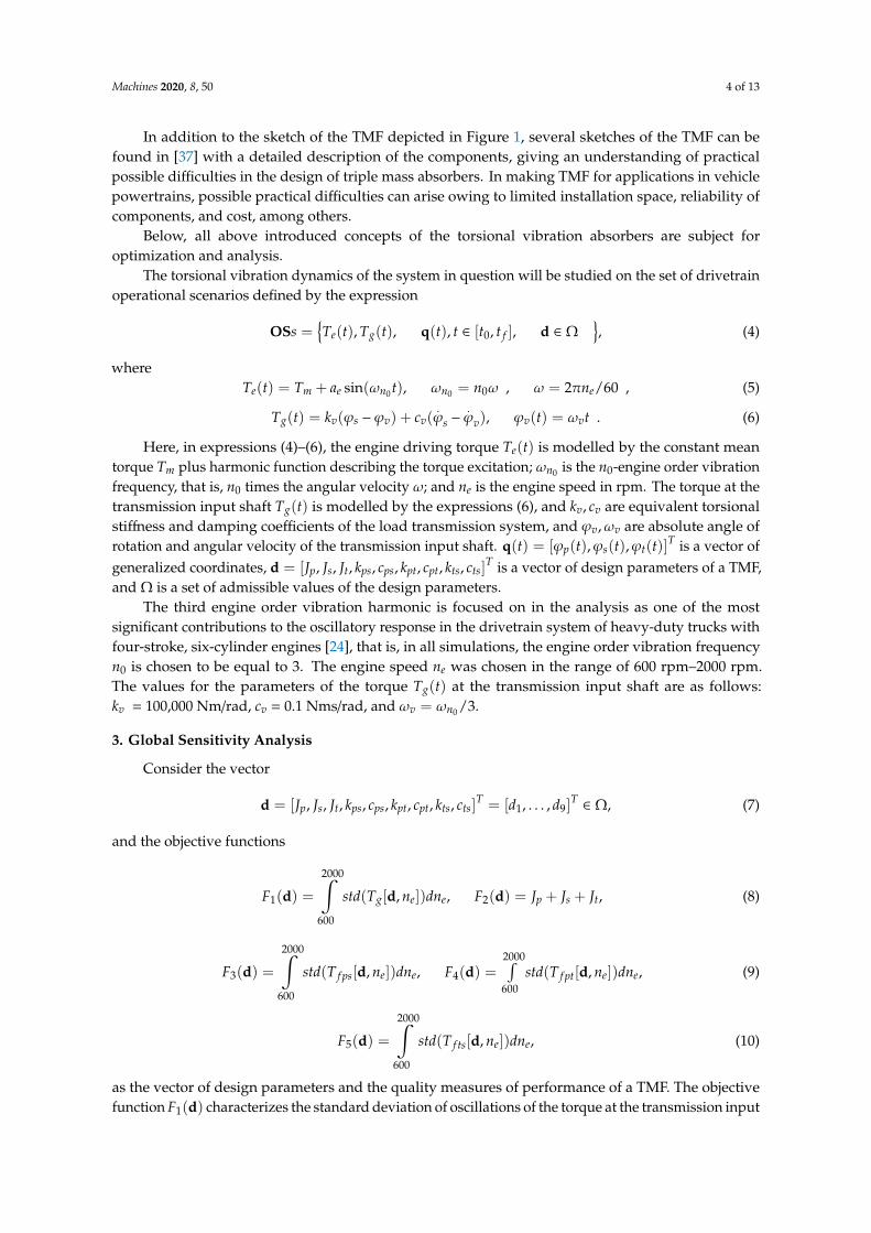
In addition to the sketch of the TMF depicted in Figure 1, several sketches of the TMF can befound in [37] with a detailed description of the components, giving an understanding of practicalpossible difficulties in the design of triple mass absorbers. In making TMF for applications in vehiclepowertrains, possible practical difficulties can arise owing to limited installation space, reliability ofcomponents, and cost, among others.
Below, all above introduced concepts of the torsional vibration absorbers are subject foroptimization and analysis.
The torsional vibration dynamics of the system in question will be studied on the set of drivetrainoperational scenarios defined by the expression
OSs =Te(t), Tg(t), q(t), t ∈ [t0, t f ], d ∈ Ω
, (4)
whereTe(t) = Tm + ae sin(ωn0 t), ωn0 = n0ω , ω = 2πne/60 , (5)
Tg(t) = kv(ϕs −ϕv) + cv(.ϕs −
.ϕv), ϕv(t) = ωvt . (6)
Here, in expressions (4)–(6), the engine driving torque Te(t) is modelled by the constant meantorque Tm plus harmonic function describing the torque excitation; ωn0 is the n0-engine order vibrationfrequency, that is, n0 times the angular velocity ω; and ne is the engine speed in rpm. The torque at thetransmission input shaft Tg(t) is modelled by the expressions (6), and kv, cv are equivalent torsionalstiffness and damping coefficients of the load transmission system, and ϕv,ωv are absolute angle ofrotation and angular velocity of the transmission input shaft. q(t) = [ϕp(t),ϕs(t),ϕt(t)]
T is a vector ofgeneralized coordinates, d = [Jp, Js, Jt, kps, cps, kpt, cpt, kts, cts]
T is a vector of design parameters of a TMF,and Ω is a set of admissible values of the design parameters.
The third engine order vibration harmonic is focused on in the analysis as one of the mostsignificant contributions to the oscillatory response in the drivetrain system of heavy-duty trucks withfour-stroke, six-cylinder engines [24], that is, in all simulations, the engine order vibration frequencyn0 is chosen to be equal to 3. The engine speed ne was chosen in the range of 600 rpm–2000 rpm.The values for the parameters of the torque Tg(t) at the transmission input shaft are as follows:kv = 100,000 Nm/rad, cv = 0.1 Nms/rad, and ωv = ωn0 /3.
3. Global Sensitivity Analysis
Consider the vector
d = [Jp, Js, Jt, kps, cps, kpt, cpt, kts, cts]T = [d1, . . . , d9]
T∈ Ω, (7)
and the objective functions
F1(d) =
2000∫600
std(Tg[d, ne])dne, F2(d) = Jp + Js + Jt, (8)
F3(d) =
2000∫600
std(T f ps[d, ne])dne, F4(d) =2000∫600
std(T f pt[d, ne])dne, (9)
F5(d) =
2000∫600
std(T f ts[d, ne])dne, (10)
as the vector of design parameters and the quality measures of performance of a TMF. The objectivefunction F1(d) characterizes the standard deviation of oscillations of the torque at the transmission input

Machines 2020, 8, 50 5 of 13
shaft in the operating engine speed range 600 rpm ≤ ne ≤ 2000 rpm The function F2(d) characterizesthe mass inertia of a TMF and is relevant for estimation of the total weight and installation space of theabsorber. The objective functions (9) and (10) characterize the friction torques and energy dissipationat the stiffness-damping interface of a TMF.
In this paper, the global sensitivity analysis (GSA) is used to study how the variation of the designparameters affect the chosen objective functions Fm(d), m = 1, ...5. The total sensitivity index of theobjective function Fm(d) is determined by the following expression [39]:
STi (Fm) ≈
1− α2i /βi
1−(∏k
j=1 α2j /β j
) . (11)
Here, α j ≈N∑
l=1w jlFm
(d jl, c− jl
), β j ≈
N∑l=1
w jl[Fm
(d jl, c− jl
)]2, Fm(di, c−i) denotes the function value
for the case that all inputs except di are fixed at their respective cut point coordinates, c = [c1, . . . , ck]T;
N is the total number of integration points; and d jl and w jl are the lth Gaussian integration abscissasand corresponding weight, respectively. More details on the algorithm of the GSA and its applicationcan be found in [19,39–41].
The following problem is formulated.
Problem GSA. For given feasible operational scenario O~S ∈ OSs defined by the expressions (4)–(6),
it is required, using relationship Equation (11), to determine the total sensitivity indices STi (Fm) of the
objective functions (8)–(10) for all varying design parameters Equation (7), subject to Equations (1),given the initial state and the restriction d ∈ Ω.
The solution of the Problem GSA was obtained by using in-house developed computer codeSAMO [42]. The SAMO stands for Sensitivity Analysis and Multi-objective Optimization (SAMO)and is a computer code implemented in MATLAB© to carry out a computationally efficient globalsensitivity analysis and multi-objective optimization of engineering systems. The sensitivity analysisworks based on the multiplicative dimensional reduction method [39]. To carry out the multi-objectiveoptimization the genetic algorithm is used [33]. More details how simulation is conducted can befound in SAMO Tutorial [42].
The nominal values of the absorber’s design parameters were chosen as follows:
Jp = 1.8 kgm2, Js = 0.9 kgm2, kps = 12732 Nm/rad, cps = 30 Nms/rad (12)
Jt = 0.3 kgm2, kpt = kts = 2000 Nm/rad, cpt = cts = 30 Nms/rad. (13)
The values of the design parameters (12) are feasible for application of the DMF in heavy-dutytruck drivetrain systems [24].
The analysis was done using nominal values (12) and (13), a normal distribution of the varyingparameters with coefficient of variation equal to 0.1, and the following lower and upper bounds fordesign parameters:
Ω =
Jp ∈ [0.2, 2.4], Js ∈ [0.1, 1.2], Jt ∈ [0.05, 0.45]kps, kpt, kts ∈ [2000, 12, 000], cps, cpt, cts ∈ [0, 150]
. (14)
The solutions of problem GSA obtained for the psptsTMF in the case of low and high levels of meanvalue of engine driving torque Te(t) in the operation engine speed range 600 rpm ≤ ne ≤ 2000 rpm areshown in Figure 2a,b. The solution is presented by means of mapping between the design parametersJp, Js, Jt, kps, cps, kpt, cpt, kts, cts and the values of the total sensitivity indices of the objective functions(8)–(10).

Machines 2020, 8, 50 6 of 13
Machines 2020, 8, x FOR PEER REVIEW 6 of 13
[0.2,2.4], [0.1,1.2], [0.05,0.45].
, , [2000,12 000], , , [0,150]p s t
ps pt ts ps pt ts
J J Jk k k c c c
∈ ∈ ∈ Ω = ∈ ∈ , (14)
The solutions of problem GSA obtained for the psptsTMF in the case of low and high levels of mean value of engine driving torque ( )eT t in the operation engine speed range 600rpm 2000rpmen≤ ≤ are shown in Figure 2a,b. The solution is presented by means of mapping between the design parameters , , , , , , , ,p s t ps ps pt pt ts tsJ J J k c k c k c and the values of the total sensitivity indices of the objective functions (8)–(10).
(a) (b)
Figure 2. Sensitivity indices of the objective functions (8)–(10) for the drivetrain equipped with the psptsTMF: (a) for 300Nm, 500Nmm eT a= = ; (b) for 3000Nm, 3000Nmm eT a= = .
4. Weight-Vibration Pareto Optimization
The Pareto optimization problem for the vehicle drivetrain equipped with a TMF is formulated as follows.
Problem WV-PO. For given feasible operational scenario s∈OS OS defined by the expressions (4)–(6), it is required to determine the vector of the design parameters of the TMF
* * * * * * * * * *[ , , , , , , , , ] ,Tp s t ps ps pt pt ts tsJ J J k c k c k c= =d d (15)
and the vector of generalized coordinates *( ) ( )t t=q q that satisfy the system of variational Equations
2000 2000* * *
1600 600
* * *max max
1 1( [ ( ), , ]) ( [ ( ), , ]) ( ),
( ) / ( ) /
min
min
g e e g e em m
p s t p s t
std T t n dn std T t n dn FT T
J J J J J J J J
∈Ω
∈Ω
= = + + = + +
d
d
q d q d d (16)
subject to differential Equations (1), given initial state and the restrictions on the design parameters Equation (14).
The Equation (16) express the requirements on the vector of design parameters *d and the vector of generalized coordinates * ( )tq to guarantee the best attenuation of oscillation of the torque at the transmission input shaft, and at the same time to minimize the total mass inertia of the vibration absorber.
The solutions of the problem WV-PO for all five torsional vibration absorbers, that is, for the psptsTMF, the psptTMF, the pstsTMF, the ptsTME, and for the DMF, were obtained using the computer code SAMO [42]. The setting of the genetic algorithm for optimization was as follows: population size = 100, number of generations = 100, elite count = 4, and Pareto fraction = 1.
Figure 2. Sensitivity indices of the objective functions (8)–(10) for the drivetrain equipped with thepsptsTMF: (a) for Tm = 300 Nm, ae = 500 Nm ; (b) for Tm = 3000 Nm, ae = 3000 Nm .
4. Weight-Vibration Pareto Optimization
The Pareto optimization problem for the vehicle drivetrain equipped with a TMF is formulatedas follows.
Problem WV-PO. For given feasible operational scenario O~S ∈ OSs defined by the expressions
(4)–(6), it is required to determine the vector of the design parameters of the TMF
d = [J∗p, J∗s , J∗t , k∗ps, c∗ps, k∗pt, c∗pt, k∗ts, c∗ts]T = d∗, (15)
and the vector of generalized coordinates q(t) = q∗(t) that satisfy the system of variational Equationsmind∈Ω
1Tm
2000∫600
std(Tg[q(t), d, ne])dne
= 1Tm
2000∫600
std(Tg[q∗(t), d∗, ne])dne = F1(d∗)
mind∈Ω
(Jp + Js + Jt)/Jmax
= (J∗p + J∗s + J∗t )/Jmax
, (16)
subject to differential Equations (1), given initial state and the restrictions on the design parametersEquation (14).
The Equation (16) express the requirements on the vector of design parameters d∗ and thevector of generalized coordinates q∗(t) to guarantee the best attenuation of oscillation of the torqueat the transmission input shaft, and at the same time to minimize the total mass inertia of thevibration absorber.
The solutions of the problem WV-PO for all five torsional vibration absorbers, that is, for thepsptsTMF, the psptTMF, the pstsTMF, the ptsTME, and for the DMF, were obtained using the computercode SAMO [42]. The setting of the genetic algorithm for optimization was as follows: population size= 100, number of generations = 100, elite count = 4, and Pareto fraction = 1.
The Pareto fronts between the normalized objective functions F1(d) = 1Tm
2000∫600
std(Tg[q(t), d, ne])dne
and F2(d) = (Jp + Js + Jt)/Jmax, obtained by solving the above formulated optimization problem,are shown in Figure 3a,b.
Machines 2020, 8, 50 7 of 13
Machines 2020, 8, x FOR PEER REVIEW 7 of 13
The Pareto fronts between the normalized objective functions 2000
1600
1( ) ( [ ( ), , ])g e em
F std T t n dnT
= d q d
and 2 max( ) ( ) /p s tF J J J J= + +d , obtained by solving the above formulated optimization problem, are shown in Figure 3a,b.
(a)
(b)
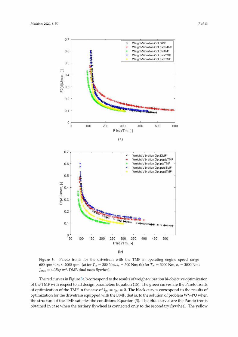
Figure 3. Pareto fronts for the drivetrain with the TMF in operating engine speed range 600rpm 2000rpmen≤ ≤ : (a) for 300 , 500m eT Nm a Nm= = ; (b) for 3000 , 3000m eT Nm a Nm= = ;
2max 4.05J kgm= . DMF, dual mass flywheel.
The red curves in Figure 3a,b correspond to the results of weight-vibration bi-objective optimization of the TMF with respect to all design parameters Equation (15). The green curves are
Figure 3. Pareto fronts for the drivetrain with the TMF in operating engine speed range600 rpm ≤ ne ≤ 2000 rpm: (a) for Tm = 300 Nm, ae = 500 Nm; (b) for Tm = 3000 Nm, ae = 3000 Nm;Jmax = 4.05kg m2. DMF, dual mass flywheel.
The red curves in Figure 3a,b correspond to the results of weight-vibration bi-objective optimizationof the TMF with respect to all design parameters Equation (15). The green curves are the Pareto frontsof optimization of the TMF in the case of kps = cps = 0. The black curves correspond to the results ofoptimization for the drivetrain equipped with the DMF, that is, to the solution of problem WV-PO whenthe structure of the TMF satisfies the conditions Equation (3). The blue curves are the Pareto frontsobtained in case when the tertiary flywheel is connected only to the secondary flywheel. The yellow

Machines 2020, 8, 50 8 of 13
curves represent the results of weight-vibration bi-objective optimization of the TMF with tertiaryflywheel connected only to the primary flywheel.
Every point of the Pareto front corresponds to the vector of the design parameters d∗ andthe respective vector of generalized coordinates q(t) = q∗(t) of the absorber. The obtainedvalues of the design parameters Equation (15) minimizing the objective function
F1(d) = 1Tm
2000∫600
std(Tg[q(t), d, ne])dne for the considered vibration absorbers in operating engine
speed range 600 rpm ≤ ne ≤ 2000 rpm with the mean value of the engine driving torque Tm = 300 Nmand the amplitude of its harmonic excitation ae = 500 Nm, as well as for the Tm = 3000 Nm andae = 3000 Nm, are presented in Tables 1 and 2, respectively.
Table 1. Results of the solution of problem weight-vibration Pareto optimization (WV-PO), Tm = 300 Nm,ae = 500 Nm. TMF, triple mass flywheel; DMF, dual mass flywheel.
Optimized Design Parameters
d*=[J*p,J*
s,J*t ,k*
ps,c*ps,k*
pt,c*pt,k
*ts,c*
ts]T psptsTMF psptTMF
(kts = cts = 0)pstsTMF
(kpt = cpt = 0)ptsTMF
(kps = cps = 0)DMFJt = 0
J∗p, (kgm2) 1.48 1.67 1.98 1.50 2.34
J∗s , (kgm2) 0.11 0.10 0.10 0.11 0.10
J∗t , (kgm2) 0.34 0.08 0.35 0.14 -
k∗ps, (Nm/rad) 2683 3132 3165 - 3938
c∗ps, (Nms/rad) 18 21 27 - 30
k∗pt, (Nm/rad) 6216 7399 - 3033 -
c∗pt, (Nms/rad) 12 74 - 91 -
k∗ts, (Nm/rad) 2764 - 7502 4995 -
c∗ts, (Nms/rad) 12 - 29 9 -
F1(d∗), (-) 110 117 114 95 118
J = Jp + Js + Jt, (kgm2) 1.93 1.85 2.43 1.75 2.44
Table 2. Results of the solution of problem WV-PO, Tm = 3000 Nm, ae = 3000 Nm.
Optimized Design Parameters
d*=[J*p,J*
s,J*t ,k*
ps,c*ps,k*
pt,c*pt,k
*ts,c*
ts]T psptsTMF psptTMF
(kts = cts = 0)pstsTMF
(kpt = cpt = 0)ptsTMF
(kps = cps = 0)DMFJt = 0
J∗p, (kgm2) 1.44 1.43 1.98 1.30 1.88
J∗s , (kgm2) 0.11 0.11 0.10 0.11 0.11
J∗t , (kgm2) 0.40 0.07 0.35 0.08 -
k∗ps, (Nm/rad) 2843 3201 3334 - 3069
c∗ps, (Nms/rad) 25 25 37 - 33
k∗pt, (Nm/rad) 6332 7190 - 4309 -
c∗pt, (Nms/rad) 17 71 - 124 -
k∗ts, (Nm/rad) 3786 - 7349 5142 -
c∗ts, (Nms/rad) 18 - 29 14 -
F1(d∗), (-) 94 98 96 86 99
J = Jp + Js + Jt, (kgm2) 1.94 1.61 2.43 1.49 1.99
Machines 2020, 8, 50 9 of 13
5. Discussion
The chosen objective functions (8)–(10) are appropriate to focus the design process for the vibrationabsorber on the best attenuation of the oscillation of the torque at the transmission input shaft,to minimize total mass inertia, as well as to analyze the energy dissipation in the stiffness-dampinginterface of the absorber.
The results of the GSA of the performance of TMF, presented in Section 3 (Figure 2a,b), make itpossible to conclude the following. For the drivetrain system in the operating engine speed range600 rpm ≤ ne ≤ 2000 rpm , with both low and high mean values of the engine driving torques,the moment of inertia of the primary flywheel, Jp, as well as the stiffness between the primary andsecondary flywheels, kps, mostly affect the oscillation of the torque at the transmission input shaftand the energy dissipation of the vibration absorber (Figure 2a,b, sensitivity indices for F1(d) andF3(d)). The energy dissipation in the stiffness-damping interface between the primary and the tertiaryflywheels, and between the tertiary and the secondary flywheels, are mostly affected by the momentof inertia of the tertiary flywheel, Jt, and the parameters kpt,cpt and kts,cts , respectively, (Figure 2a,b,sensitivity indices for F4(d) and F5(d)).
The solutions of the Pareto optimization problem, presented in Section 4, show that there exists atrade-off between the measure of the oscillation attenuation of the torque at the transmission inputshaft and the total mass inertia characteristic of the drivetrain system equipped with the TMF in theoperating engine speed range 600 rpm≤ ne ≤ 2000 rpm for both low and high mean values of the enginedriving torques (Figure 3a,b). Analysis of the obtained Pareto fronts shows that at least two conceptsof the TMF, namely the ptsTMF (green curves) and the psptTMF (yellow curves), are in significantsuperior positions in comparison with the optimized DMF (black curves). As follows from the valuesof F1(d∗) for the ptsTMF and the DMF (Tables 1 and 2), the use of the optimized in the drivetrainsystem improves up to 20% the attenuation of the oscillations of the torque at the transmission inputshaft in comparison with the attenuation of the oscillations of the torque in the case of using theoptimized DMF.
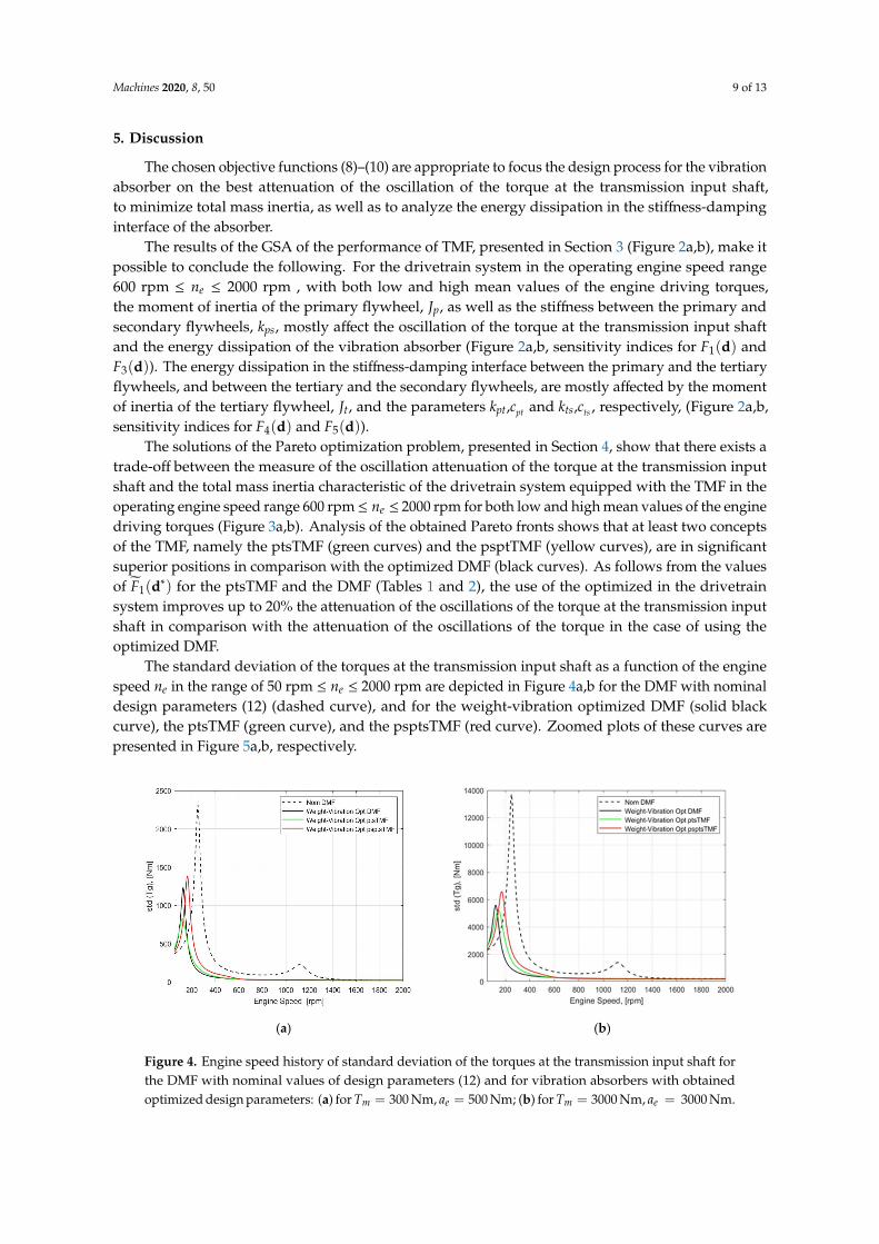
The standard deviation of the torques at the transmission input shaft as a function of the enginespeed ne in the range of 50 rpm ≤ ne ≤ 2000 rpm are depicted in Figure 4a,b for the DMF with nominaldesign parameters (12) (dashed curve), and for the weight-vibration optimized DMF (solid blackcurve), the ptsTMF (green curve), and the psptsTMF (red curve). Zoomed plots of these curves arepresented in Figure 5a,b, respectively.
Machines 2020, 8, x FOR PEER REVIEW 9 of 13
p s tJ J J J= + + , (kgm2) 1.94 1.61 2.43 1.49 1.99
5. Discussion
The chosen objective functions (8)–(10) are appropriate to focus the design process for the vibration absorber on the best attenuation of the oscillation of the torque at the transmission input shaft, to minimize total mass inertia, as well as to analyze the energy dissipation in the stiffness-damping interface of the absorber.
The results of the GSA of the performance of TMF, presented in Section 3 (Figure 2a,b), make it possible to conclude the following. For the drivetrain system in the operating engine speed range 600 2000erpm n rpm≤ ≤ , with both low and high mean values of the engine driving torques, the moment of inertia of the primary flywheel, pJ , as well as the stiffness between the primary and secondary flywheels, psk , mostly affect the oscillation of the torque at the transmission input shaft and the energy dissipation of the vibration absorber (Figure 2a,b, sensitivity indices for 1( )F d and
3 ( )F d ). The energy dissipation in the stiffness-damping interface between the primary and the tertiary flywheels, and between the tertiary and the secondary flywheels, are mostly affected by the moment of inertia of the tertiary flywheel, tJ , and the parameters ptk ,
ptc and tsk ,
tsc , respectively,
(Figure 2a,b, sensitivity indices for 4 ( )F d and 5 ( )F d ). The solutions of the Pareto optimization problem, presented in Section 4, show that there exists
a trade-off between the measure of the oscillation attenuation of the torque at the transmission input shaft and the total mass inertia characteristic of the drivetrain system equipped with the TMF in the operating engine speed range 600rpm 2000rpmen≤ ≤ for both low and high mean values of the engine driving torques (Figure 3a,b). Analysis of the obtained Pareto fronts shows that at least two concepts of the TMF, namely the pstTMF (green curves) and the psptTMF (yellow curves), are in significant superior positions in comparison with the optimized DMF (black curves). As follows from the values of *
1( )F d for the pstTMF and the DMF (Tables 1 and 2), the use of the optimized pstTMF in the drivetrain system improves up to 20% the attenuation of the oscillations of the torque at the transmission input shaft in comparison with the attenuation of the oscillations of the torque in the case of using the optimized DMF.
The standard deviation of the torques at the transmission input shaft as a function of the engine speed en in the range of 50rpm 2000rpmen≤ ≤ are depicted in Figure 4a,b for the DMF with nominal design parameters (12) (dashed curve), and for the weight-vibration optimized DMF (solid black curve), the ptsTMF (green curve), and the psptsTMF (red curve). Zoomed plots of these curves are presented in Figure 5a,b, respectively.
(a) (b)
Figure 4. Engine speed history of standard deviation of the torques at the transmission input shaft forthe DMF with nominal values of design parameters (12) and for vibration absorbers with obtainedoptimized design parameters: (a) for Tm = 300 Nm, ae = 500 Nm; (b) for Tm = 3000 Nm, ae = 3000 Nm.
Machines 2020, 8, 50 10 of 13
Machines 2020, 8, x FOR PEER REVIEW 10 of 13
Figure 4. Engine speed history of standard deviation of the torques at the transmission input shaft for the DMF with nominal values of design parameters (12) and for vibration absorbers with obtained optimized design parameters: (a) for 300Nm, 500Nmm eT a= = ; (b) for 3000 , 3000m eT Nm a Nm= = .
(a) (b)
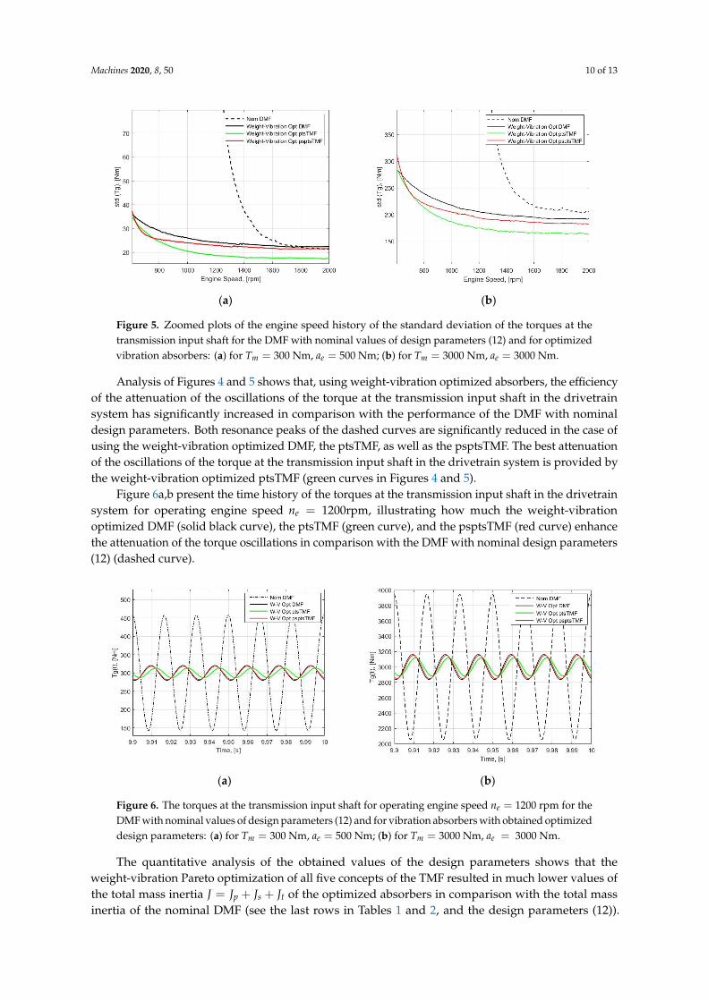
Figure 5. Zoomed plots of the engine speed history of the standard deviation of the torques at the transmission input shaft for the DMF with nominal values of design parameters (12) and for optimized vibration absorbers: (a) for 300Nm, 500Nmm eT a= = ; (b) for 3000 , 3000m eT Nm a Nm= = .
Analysis of Figures 4 and 5 shows that, using weight-vibration optimized absorbers, the efficiency of the attenuation of the oscillations of the torque at the transmission input shaft in the drivetrain system has significantly increased in comparison with the performance of the DMF with nominal design parameters. Both resonance peaks of the dashed curves are significantly reduced in the case of using the weight-vibration optimized DMF, the ptsTMF, as well as the psptsTMF. The best attenuation of the oscillations of the torque at the transmission input shaft in the drivetrain system is provided by the weight-vibration optimized ptsTMF (green curves in Figures 4 and 5).
Figure 6a,b present the time history of the torques at the transmission input shaft in the drivetrain system for operating engine speed 1200rpmen = , illustrating how much the weight-vibration optimized DMF (solid black curve), the pstTMF (green curve), and the psptsTMF (red curve) enhance the attenuation of the torque oscillations in comparison with the DMF with nominal design parameters (12) (dashed curve).
(a) (b)
Figure 6. The torques at the transmission input shaft for operating engine speed 1200rpmen = for the
DMF with nominal values of design parameters (12) and for vibration absorbers with obtained optimized design parameters: (a) for 300Nm, 500Nmm eT a= = ; (b) for 3000 , 3000m eT Nm a Nm= = .
Figure 5. Zoomed plots of the engine speed history of the standard deviation of the torques at thetransmission input shaft for the DMF with nominal values of design parameters (12) and for optimizedvibration absorbers: (a) for Tm = 300 Nm, ae = 500 Nm; (b) for Tm = 3000 Nm, ae = 3000 Nm.
Analysis of Figures 4 and 5 shows that, using weight-vibration optimized absorbers, the efficiencyof the attenuation of the oscillations of the torque at the transmission input shaft in the drivetrainsystem has significantly increased in comparison with the performance of the DMF with nominaldesign parameters. Both resonance peaks of the dashed curves are significantly reduced in the case ofusing the weight-vibration optimized DMF, the ptsTMF, as well as the psptsTMF. The best attenuationof the oscillations of the torque at the transmission input shaft in the drivetrain system is provided bythe weight-vibration optimized ptsTMF (green curves in Figures 4 and 5).
Figure 6a,b present the time history of the torques at the transmission input shaft in the drivetrainsystem for operating engine speed ne = 1200rpm, illustrating how much the weight-vibrationoptimized DMF (solid black curve), the ptsTMF (green curve), and the psptsTMF (red curve) enhancethe attenuation of the torque oscillations in comparison with the DMF with nominal design parameters(12) (dashed curve).
Machines 2020, 8, x FOR PEER REVIEW 10 of 13
Figure 4. Engine speed history of standard deviation of the torques at the transmission input shaft for the DMF with nominal values of design parameters (12) and for vibration absorbers with obtained optimized design parameters: (a) for 300Nm, 500Nmm eT a= = ; (b) for 3000 , 3000m eT Nm a Nm= = .
(a) (b)
Figure 5. Zoomed plots of the engine speed history of the standard deviation of the torques at the transmission input shaft for the DMF with nominal values of design parameters (12) and for optimized vibration absorbers: (a) for 300Nm, 500Nmm eT a= = ; (b) for 3000 , 3000m eT Nm a Nm= = .
Analysis of Figures 4 and 5 shows that, using weight-vibration optimized absorbers, the efficiency of the attenuation of the oscillations of the torque at the transmission input shaft in the drivetrain system has significantly increased in comparison with the performance of the DMF with nominal design parameters. Both resonance peaks of the dashed curves are significantly reduced in the case of using the weight-vibration optimized DMF, the ptsTMF, as well as the psptsTMF. The best attenuation of the oscillations of the torque at the transmission input shaft in the drivetrain system is provided by the weight-vibration optimized ptsTMF (green curves in Figures 4 and 5).
Figure 6a,b present the time history of the torques at the transmission input shaft in the drivetrain system for operating engine speed 1200rpmen = , illustrating how much the weight-vibration optimized DMF (solid black curve), the pstTMF (green curve), and the psptsTMF (red curve) enhance the attenuation of the torque oscillations in comparison with the DMF with nominal design parameters (12) (dashed curve).
(a) (b)
Figure 6. The torques at the transmission input shaft for operating engine speed 1200rpmen = for the
DMF with nominal values of design parameters (12) and for vibration absorbers with obtained optimized design parameters: (a) for 300Nm, 500Nmm eT a= = ; (b) for 3000 , 3000m eT Nm a Nm= = .
Figure 6. The torques at the transmission input shaft for operating engine speed ne = 1200 rpm for theDMF with nominal values of design parameters (12) and for vibration absorbers with obtained optimizeddesign parameters: (a) for Tm = 300 Nm, ae = 500 Nm; (b) for Tm = 3000 Nm, ae = 3000 Nm.
The quantitative analysis of the obtained values of the design parameters shows that theweight-vibration Pareto optimization of all five concepts of the TMF resulted in much lower values ofthe total mass inertia J = Jp + Js + Jt of the optimized absorbers in comparison with the total massinertia of the nominal DMF (see the last rows in Tables 1 and 2, and the design parameters (12)).

Machines 2020, 8, 50 11 of 13
For instance, the total mass inertia of the optimized pstTMF is up to 28% less in comparison with thetotal mass inertia of the optimized DMF (see Table 1). The above mentioned is a significant advantageof the weight-vibration optimized TMF for its implementation in real drivetrain systems.
6. Conclusions and Outlook
The results obtained demonstrate the efficiency of the methodology based on global sensitivityanalysis and Pareto optimization for the design of novel multiple-mass torsional vibration absorbersfor vehicle powertrains. The methodology can also be used for multi-objective optimal design oftorsional vibration absorbers for other rotor-dynamical systems subjected to oscillatory excitations.The following concluding remarks can be drawn.
• There exists evidence of feasibility of the application of weight-vibration optimized triple massflywheels in heavy-duty trucks powertrains.
• For a heavy-duty truck powertrain equipped with a triple mass flywheel, there exists theweight-vibration bi-objective optimized mass inertia, as well as stiffness and damping parametersproviding the trade-off between the level of attenuation of the oscillations of the torque at thetransmission input shaft and the total mass inertia of the absorber in the operating engine speedrange 600 rpm ≤ ne ≤ 2000 rpm when the third engine order vibration harmonic is in focus.
• The weight-vibration optimized design parameters of a triple mass flywheel providing the bestattenuation of oscillations of the torque at the transmission input shaft can put this concept in asuperior position in comparison with the weight-vibration optimized dual mass flywheel.
The above-mentioned points highlight the advantages of triple mass flywheels for technology oftorsional vibration attenuation in vehicle powertrains.
Design optimization problems for a triple-mass flywheel within a complete model of a drivetrainsystem of a heavy-duty truck, as well as validation of the results obtained using experimental data, areimportant steps for future research [18,43].
Funding: This research was partially funded by the Swedish Energy Agency, project No. 42100-1.
Conflicts of Interest: The author declares no conflict of interest.
References
1. Albers, A. Advanced development of dual mass flywheel (DMFW) design-noise control for today’sautomobiles. In 5th LuK Symposium; Schaeffler: Bühl, Germany, 1994; pp. 24–41.
2. Kim, T.H.; Song, H.L.; Hwang, S.H.; Kim, H.S. Analysis of dual mass flywheel using discreet arcspringmodel. Key Eng. Mater. 2006. [CrossRef]
3. Mahl, T.; Sawodny, O. Modelling of an automotive dual mass flywheel. In IFAC Proceedings; IFAC: Laxenburg,Austria, 2010; Volume 43, pp. 517–523. [CrossRef]
4. Song, L.Q.; Zeng, L.P.; Zhang, S.P.; Zhou, J.D.; Niu, H.E. Design and analysis of a dual mass flywheel withcontinuously variable stiffness based on compensation principle. Mech. Mach. Theory 2014, 79, 124–140.[CrossRef]
5. Chen, L.; Zeng, R.; Jiang, Z. Nonlinear dynamical model of an automotive dual mass flywheel. Adv. Mech. Eng.2015, 7, 1–11. [CrossRef]
6. Fidlin, A.; Mall, P. On the effect of the distributed friction in the arc spring on the dynamic behavior of theautomotive transmission. In Proceedings of the International Conference on Engineering Vibrations, ICoEV 2015;National and University Library of Slovenia: Ljubljana, Slovenia, 2015; pp. 1099–1108.
7. Gupta, K.; Choudhary, A.; Bidre, R. NVH Performance Improvement Study Using a Dual Mass Flywheel(DMF), Inertia Ring Type Tuned Torsional Vibration Damper (TVD) and Single Mass Flywheel (SMF) in aFront Engine and Rear Wheel Driveline Architecture. SAE Tech. Pap. 2017. [CrossRef]
8. Mall, P.; Fidlin, A.; Krüger, A.; Groß, H. Simulation based optimization of torsional vibration dampers inautomotive powertrains. Mech. Mach. Theory 2017, 115, 244–266. [CrossRef]
Machines 2020, 8, 50 12 of 13
9. Faust, H. Powertrain systems of the future—engine, transmission and damper systems for downspeeding,downsizing and cylinder deactivation. In 10th Schaeffler Symposium; Schaeffler Technologies GmbH & Co. KG:Baden-Baden, Germany, 2014; pp. 24–41. [CrossRef]
10. Haddow, A.; Shaw, S. Centrifugal Pendulum Vibration Absorbers: An Experimental and TheoreticalInvestigation. Nonlinear Dyn. 2003, 34, 293–307. [CrossRef]
11. Haris, A.; Motato, E.; Theodossiades, S.; Rahnejat, H.; Kelly, P.; Vakakis, A.; Bergman, L.; McFarland, D.M.A study on torsional vibration attenuation in automotive drivetrains using absorbers with smooth andnon-smooth nonlinearities. Appl. Math. Model. 2017, 46, 674–690. [CrossRef]
12. Kooy, A. Best-in-class dampers for every driveline concept. In Schaeffler Symposium; Schaeffler: Baden-Baden,Germany, 2018; pp. 146–160.
13. Haris, A.; Motato, E.; Mohammadpour, M.; Thedossiades, S.; Rahnejat, H.; O’ Mahony, M.; Vakakis, A.F.;Bergman, L.A.; McFarland, D.M. On the effect of multiple parallel nonlinear absorbers in palliation oftorsional response of automotive drivetrain. Int. J. Non-Linear Mech. 2017, 96, 22–35. [CrossRef]
14. Motato, E.; Haris, A.; Thedossiades, S.; Mohammadpour, M.; Rahnejat, H.; Kelly, P.; Vakakis, A.F.;McFarland, D.M.; Bergman, L.A. Targeted energy transfer and modal energy redistribution in automotivedrivetrains. Nonlinear Dyn. 2017, 87, 169–190. [CrossRef]
15. Chen, Z.; Chen, Z.; Mao, Y.; Shi, W.; Zhang, G. Control Research of Power Train Torsional Vibration Based onMagneto-Rheological Fluid Dual Mass Flywheel. SAE Tech. Pap. 2014. [CrossRef]
16. Zu, Q.-h.; Chen, Z.-Y.; Shi, W.-K.; Mao, Y.; Chen, Z.-Y. Torsional Vibration Semiactive Control of DrivetrainBased on Magnetorheological Fluid Dual Mass Flywheel. Math. Probl. Eng. Hindawi Publ. Corp. 2015.[CrossRef]
17. Dong, X.; Li, W.; Yu, J.; Pan, C.; Xi, J.; Zhou, Y.; Wang, X. Magneto-Rheological Variable Stiffness and DampingTorsional Vibration Control of Powertrain System. Front. Mater. 2020. [CrossRef]
18. Wramner, L.; Berbyuk, V.; Johansson, H. Vibration dynamics in non-linear dual mass flywheels for heavy-dutytrucks. In The 28th Edition of the Biennial ISMA Conference on Noise and Vibration Engineering; KU Leuven:Leuven, Belgium, 2018; pp. 1863–1876.
19. Berbyuk, V. Design optimization of torsional vibration absorbers for heavy-duty truck drivetrain systems.Vibration 2019, 2, 240–264. [CrossRef]
20. Berbyuk, V. Weight-vibration Pareto optimization of a dual mass flywheel. Math. Methods Phys. Fields 2019,62, 7–18.
21. Berbyuk, V. Towards the limits of vibration attenuation in drivetrain system by torsional dynamics absorber.In Advances in Dynamics of Vehicles on Roads and Tracks. IAVSD 2019; Klomp, M., Bruzelius, F., Nielsen, J.,Hillemyr, A., Eds.; Lecture Notes in Mechanical Engineering; Springer: Berlin/Heidelberg, Germany, 2020;pp. 1574–1583. [CrossRef]
22. Wramner, L. Dual mass flywheel with tuned vibration absorbers for application in heavy-duty truckpowertrains. Proc. Inst. Mech. Eng. Part D J. Automob. Eng. 2020. [CrossRef]
23. Wramner, L. Analysis of power split vibration absorber performance in heavy-duty truck powertrains.Proc. Inst. Mech. Eng. Part D J. Automob. Eng. 2020. [CrossRef]
24. Wramner, L. Torsional Vibration Absorbers in Heavy-Duty Truck Powertrains. Ph.D. Thesis,Chalmers University of Technology, Göteborg, Sweden, 2020.
25. Den Hartog, J.P. Mechanical Vibrations; Dover Publication, Inc.: New York, NY, USA, 1985.26. De Domenico, D.; Ricciardi, G. Optimal design and seismic performance of tuned mass damper inerter
(TMDI) for structures with nonlinear base isolation systems. Earthq. Eng. Struct. Dyn. 2018, 47, 2539–2560.27. Mousavi Bideleh, S.M.; Berbyuk, V. Pareto Optimization of a Nonlinear Tuned Mass Damper to Control
Vibrations in Hand Held Impact Machines. In Nonlinear Dynamics, Volume 1. Conference Proceedings of theSociety for Experimental Mechanics Series; Kerschen, G., Ed.; Springer: Berlin/Heidelberg, Germany, 2019;pp. 27–44. [CrossRef]
28. Seer, T.A.; Vahdati, N.; Shiryaev, O. Adaptive Torsional Tuned Vibration Absorber for Rotary Equipment.Vibration 2019, 2, 116–134. [CrossRef]
29. Karimaei, H.; Mehrgou, M.; Chamani, H.R. Optimisation of torsional vibration system for a heavy-dutyinline six-cylinder diesel engine. Proc Imeche Part K J. Multi-Body Dyn. 2019, 233, 642–656. [CrossRef]
30. Bazara, S.; Shetty, C. Nonlinear Programming. Theory and Algorithms; John Wiley and Sons: New York, NY,USA, 1979.
Machines 2020, 8, 50 13 of 13
31. Bagchi, T.P. Multiobjective Scheduling by Genetic Algorithmsii; Kluwer Academic Publisher: Boston, MA, USA, 1999.32. Tan, X.; Hua, L.; Lu, C.; Yang, C.; Wang, Y.; Wang, S. A new method for optimizing the parameters of torsional
vibration dampers. J. Vibroeng. 2017, 19, 4155–4171.33. McCall, J. Genetic algorithms for modelling and optimization. J. Comput. Appl. Math. 2005, 184, 205–222.
[CrossRef]34. Maeda, Y.; Nishiwaki, S.; Izui, K.; Yoshimura, M.; Matsui, K.; Terada, K. Structural topology optimization
of vibrating structures with specified eigenfrequencies and eigenmode shapes. Int. J. Numer. Methods Eng.2006, 67, 597–628. [CrossRef]
35. Chronopoulos, D. Design optimization of composite structures operating in acoustic environments.J. Sound Vib. 2015, 355, 322–344. [CrossRef]
36. Kaveh, A.; Ghazaan, M.I. Vibrating particles system algorithm for truss optimization with multiple naturalfrequency constraints. Acta Mech. 2017, 218, 307–322. [CrossRef]
37. Shaw, W.L. Triple Mass Flywheel. U.S. Patent 2019/0011010 A1, 10 January 2019.38. Olsson, H. Control Systems with Friction. Ph.D. Thesis, Lund Institute of Technology, Göteborg, Sweden, 1996.39. Zhang, X.; Pandey, M.D. An effective approximation for variance-based global sensitivity analysis. Reliab. Eng.
Syst. Saf. 2014, 121, 164–174. [CrossRef]40. Rabitz, H.; Alis, Ö. General foundations of high-dimensional model representations. J. Math. Chem. 1999, 25,
197–233. [CrossRef]41. Mousavi Bideleh, S.M.; Berbyuk, V. Global sensitivity analysis of bogie dynamics with respect to suspension
components. Multibody Syst. Dyn. 2016, 37, 145–174. [CrossRef]42. Mousavi Bideleh, S.M.; Berbyuk, V. A Computer Code for Sensitivity Analysis and Multiobjective Optimization:
SAMO Tutorial; Department of Mechanics and Maritime Sciences, Chalmers University of Technology:Gothenburg, Sweden, 2017; p. 45.
43. Karlsson, J. Investigation of Dynamic Friction Properties of a Dual Mass Flywheel for Commercial Vehicles.Master’s Thesis, Chalmers University of Technology, Göteborg, Sweden, 2018.
© 2020 by the author. Licensee MDPI, Basel, Switzerland. This article is an open accessarticle distributed under the terms and conditions of the Creative Commons Attribution(CC BY) license (http://creativecommons.org/licenses/by/4.0/).