Embed Size (px)
Citation preview

Kokkedal Industripark 4 DK-2980 Kokkedal Denmark Tel: +45 49 18 01 00 Fax: +45 49 18 02 00
Document no.:
Date:
Rev.:
WI
EIGHING CONTROLLER TYPE MCE9625L nstallation guide for system with digital loadcells and LED display
0316iu4.doc
2002-03-11
4

MCE9625L, 990316: Installation guide
1) Table of contents 1) Table of contents..............................................................................................................................2 2) Installation........................................................................................................................................3
2.1 Introduction.................................................................................................................................3 2.2 Mains...........................................................................................................................................3 2.3 Loadcell modules (MCE9610)....................................................................................................3 2.4 MCE9601 Terminal Module.......................................................................................................5 2.5 Installation of the system ............................................................................................................6 2.6 Weighing range parameters ........................................................................................................7
2.6.1 Number of loadcells..............................................................................................................7 2.6.2 Loadcell factor (optional) .....................................................................................................7 2.6.3 Other settings........................................................................................................................8
2.7 Tare compensation (Coarse taring) .............................................................................................8 2.8 Checking of loadcell connection.................................................................................................8 2.9 Corner calibration .......................................................................................................................8 2.10 Fine adjustment of calibration ..................................................................................................9 2.11 Linearization .............................................................................................................................9 2.12 Analog output signal (optional) ................................................................................................9 2.13 AUX communication ..............................................................................................................10
3) Parameter list .................................................................................................................................11 4) Status codes....................................................................................................................................13 5) Operator panel................................................................................................................................14
5.1 Introduction...............................................................................................................................14 5.2 Normal reading .........................................................................................................................14 5.3 Parameters.................................................................................................................................15
5.3.1 Parameters in Normal mode ...............................................................................................15 5.3.2 Parameters in Parameter mode...........................................................................................16
5.4 Automatic zeroing.....................................................................................................................17 5.5 Calibration.................................................................................................................................17
5.5.1 Reference load ....................................................................................................................18 5.5.2 Calibration factors ..............................................................................................................18
5.6 Loadcell status ..........................................................................................................................18 5.7 Integration period......................................................................................................................18 5.8 Language...................................................................................................................................18
6) Connections....................................................................................................................................19 6.1 MCE9629 Analog output module.............................................................................................20
6.1.1 MCE9601 connection .........................................................................................................20 6.1.2 MCE9629: J2 (digital IO)...................................................................................................21 6.1.3 MCE9629: J4 (Analog output) ...........................................................................................21 6.1.4 Connection of MCE9629 Analog module (and loadcells): ................................................22
7) Download of new software to MCE9625 ......................................................................................23 7.1 Download..................................................................................................................................23 7.2 Errors.........................................................................................................................................24
Version: 2002-03-11, rev.: 4 Page: 2

MCE9625L, 990316: Installation guide
2) Installation
2.1 Introduction This manual describes installation of the EILERSEN ELECTRIC weighing controller type MCE9625L (with LED display) with 1-8 digital loadcells with MCE9610 loadcell modules (Microchip PIC17 based):
• Connection of up to eight loadcells. All loadcells must be used in the same weigh-ing system.
• Three digital inputs (5-30VDC) and three digital outputs (24VDC). • RS485 connection between loadcells and MCE9625 display. • Two RS232 interfaces • One RS422/RS485 interface.
This manual is to be used in combination with the Users guide for the installed software and applies to software of type: STDLED, LEDLIM, LEDRCP and software derived from these standard applications.
2.2 Mains The supply should be as stable as possible. Avoid connecting the weighing terminal to the mains at points where interference generating equipment is connected. The earth connec-tion should only be made if a sufficiently noise-free earth is available (a separate earth connection may be required). It is strongly recommended that the weighing system is al-ways powered. As soon as power is applied the following will happen:
• The display unit will perform a display test; the two displays and the LEDs are switched on. By looking at the display, the user of the terminal can check that the two displays and all LEDs are operative.
• The application checksum is verified (the display will show ”CS rEAd” and then ”CS ACCEPt”).
• The display will show show ”SELECt SEtUp” to allow the user to enter BIOS setup. Please refer to the separate BIOS manual for details.
• The application program is started (the display shows ”StArt”). • The software version is displayed. • The compilation date and time of the software is displayed. • The terminal will perform a power-up print of the application version and the pa-
rameters (the display will show ”Print P.UP”; please refer to the separate Users guide for channel and communication settings).
• The terminal is now ready for weighing. If an error is present during power-on the upper display will show” --P.UP.--”, while the lower display will show the error code. To select normal reading press Esc (= Shift +
Del ). The error may then be corrected by correcting parameter setting etc.
2.3 Loadcell modules (MCE9610) Below the layout of the MCE9610 loadcell module is shown. Before using the system the loadcells must be connected to the loadcell modules. Please notice that the loadcell and the PIC in the loadcell module MUST have the same number. Loadcells and loadcell modules MUST NOT be mixed. The loadcell module MUST be connected to exactly the loadcell it is intended for and vice versa.
Version: 2002-03-11, rev.: 4 Page: 3

MCE9625L, 990316: Installation guide
All switches (SW1) in the loadcell module must be at the correction position. Please notice that the switches are only read at power-up. So if a change in the switch set-ting is necessary the power has to be disconnected and then reconnected (after 10 seconds) before the MCE9610 loadcell module recognises the new switch setting.
Flat cable connector
10 contacts
BNC connector
for loadcell
TXBB
D1SYNCERR
M CE 9 61 0E ile r s e n E le c t r ic
SW1
18
ON
The LED’s are used to indicate the following conditions:
MCE9610 LED’S TXBB Green Communication. Must be on/flashing rap-
idly whenever the system is has started the application program.
D1 Yellow No synchronisation between loadcell mod-ules: One or more loadcells not connected to loadcell module or poor connection.
SYNC ERR Red No loadcell synchronisation: No loadcell connected to loadcell module or poor con-nection.
Version: 2002-03-11, rev.: 4 Page: 4
MCE9625L, 990316: Installation guide
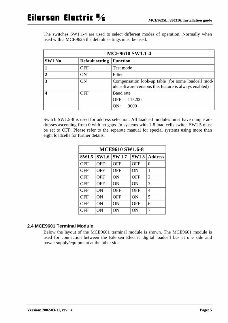
The switches SW1.1-4 are used to select different modes of operation. Normally when used with a MCE9625 the default settings must be used.
MCE9610 SW1.1-4 SW1 No Default setting Function 1 OFF Test mode 2 ON Filter 3 ON Compensation look-up table (for some loadcell mod-
ule software versions this feature is always enabled) 4 OFF Baud rate
OFF: 115200 ON: 9600
Switch SW1.5-8 is used for address selection. All loadcell modules must have unique ad-dresses ascending from 0 with no gaps. In systems with 1-8 load cells switch SW1.5 must be set to OFF. Please refer to the separate manual for special systems using more than eight loadcells for further details.
MCE9610 SW1.6-8 SW1.5 SW1.6 SW 1.7 SW1.8 Address OFF OFF OFF OFF 0 OFF OFF OFF ON 1 OFF OFF ON OFF 2 OFF OFF ON ON 3 OFF ON OFF OFF 4 OFF ON OFF ON 5 OFF ON ON OFF 6 OFF ON ON ON 7
2.4 MCE9601 Terminal Module Below the layout of the MCE9601 terminal module is shown. The MCE9601 module is used for connection between the Eilersen Electric digital loadcell bus at one side and power supply/equipment at the other side.
Version: 2002-03-11, rev.: 4 Page: 5

MCE9625L, 990316: Installation guide
D3D2D1
JU1
J2
J1
GndBAGnd+24VdcGndI/O
The J1 terminal block is used for connection of the following:
• Terminals Gnd and B (-) and A (+) gives access to the RS485 bus of all equip-ment connected to the loadcell bus. These terminals are used to connect it to the loadcell modules.
• Terminals Gnd and +24Vdc provides external power to the equipment connected to the loadcell bus. These terminals has to be connected to an external +24VDC power supply.
• Terminals Gnd and I/O are the internal syncronization signal used by the loadcell modules. Normally these terminals have no external connection and must be left open.
The J2 connector is used for connecting equipment (loadcell modules, communication modules etc.) on the digital loadcell bus by using the supplied ribbon cable with mounted connectors. The JU1 jumper is used for hardware synchronisation. Normally this jumper should be left in the default factory setting which is ON. The light emitting diodes on the MCE9601 module have the following function:
LED Function D1
(Green) RS485 Communication. This LED should be ON during normal operation (Actually it is flashing quickly, but this can look like a steady light).
D2 (Yellow)
This LED should be OFF during normal operation. If this lamp is lit, the I/O pin are at reversed polarity.
D3 (Red)
Hardware Synchronisation. This LED should be ON during normal opera-tion (Actually it is flashing quickly, but this can look like a steady light).
2.5 Installation of the system First check that the weight display is showing no status codes (the display could however be showing “OL” or “UL” to indicate that the weight is out of range). If a status code is shown please see below for the reason and correct the error. Please notice that all parameter description texts used below assumes that the language pa-rameter is set to English.
Version: 2002-03-11, rev.: 4 Page: 6

MCE9625L, 990316: Installation guide
Please notice that parameter numbers can differ slightly for some special software. Please refer to the separate Users guide for a complete description of parameters and parameter numbers. Installation of the system is done by following the instructions given in his section sequen-tially.
• Entering of number of loadcells and loadcell factor • Entering of weighing range parameters • Tare compensation (Coarse taring) • Checking loadcell connection • Corner calibration (where applicable) • Fine adjustment of calibration (where applicable) • Linearization (where applicable) • Entering of parameters for analog output (optional)
2.6 Weighing range parameters To be able to use the scale the following weighing range parameters must be entered.
Weighing range parameters Group Parameters No Display tekst Calibration Loadcell factor 19 LC. FAC.
Number of loadcells 20 LC no.
Unit (kilogram, gram or tons) 21 Unit
Decimal point position (0-3) 22 d.dPno
Display division (0.001 – 5 kg) 23 d.div.
Minimum weight 24 d. ULSP
Range Normal reading
Maximum weight 25 d. OLSP
Decimal point position (0-3) 32 c.dPno
Display division (0.001 – 5 kg) 33 c. div.
Minimum weight 34 c. ULSP
Range Calibration
Maximum weight 35 c. OLSP
2.6.1 Number of loadcells The number of loadcells connected must be entered as the first . This is done by selecting parameter reading ( F5 ), parameter 20 (”LC. no.”) and then enter the desired number (1-16). This value is used to check the number of loadcells connected during power-on. Of these values do not match an error code will be displayed (8000).
2.6.2 Loadcell factor (optional) In some programs it is possible to set the number of supports divided by the number of loadcells. This is done by selecting parameter reading ( F5 ), parameter 19 (”LC. FAC.”) and then enter the desired factor (1-6). If a tank with 3 legs has only one loadcell the value 3 is entered , while 4 legs and 2 loadcells will give the factor: 2. Please notice that this feature is optional and not present in all programs. If present the fac-tor must be entered before the parameters described below.
Version: 2002-03-11, rev.: 4 Page: 7
MCE9625L, 990316: Installation guide
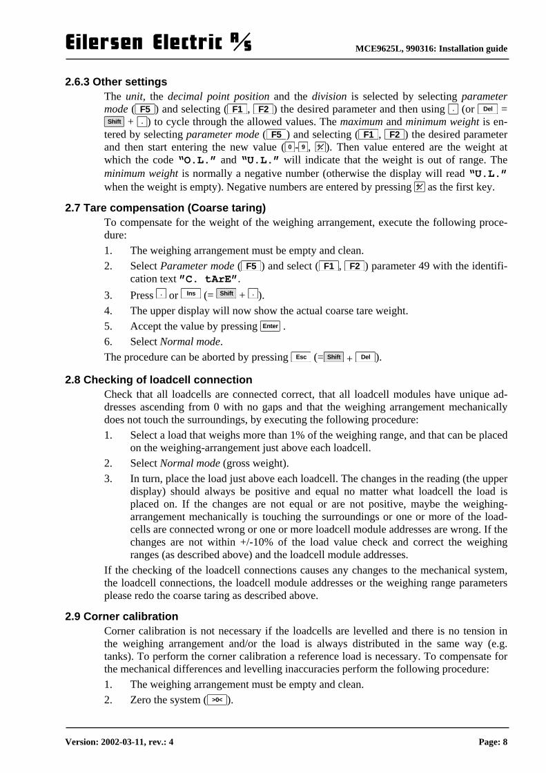
2.6.3 Other settings The unit, the decimal point position and the division is selected by selecting parameter mode ( F5 ) and selecting ( F1 , F2 ) the desired parameter and then using . (or Del = Shift + . ) to cycle through the allowed values. The maximum and minimum weight is en-
tered by selecting parameter mode ( F5 ) and selecting ( F1 , F2 ) the desired parameter and then start entering the new value ( 0 - 9 , +- ). Then value entered are the weight at which the code “O.L.” and “U.L.” will indicate that the weight is out of range. The minimum weight is normally a negative number (otherwise the display will read “U.L.” when the weight is empty). Negative numbers are entered by pressing +- as the first key.
2.7 Tare compensation (Coarse taring) To compensate for the weight of the weighing arrangement, execute the following proce-dure: 1. The weighing arrangement must be empty and clean. 2. Select Parameter mode ( F5 ) and select ( F1 , F2 ) parameter 49 with the identifi-
cation text ”C. tArE”. 3. Press . or Ins (= Shift + . ). 4. The upper display will now show the actual coarse tare weight. 5. Accept the value by pressing Enter . 6. Select Normal mode. The procedure can be aborted by pressing Esc (= Shift + Del ).
2.8 Checking of loadcell connection Check that all loadcells are connected correct, that all loadcell modules have unique ad-dresses ascending from 0 with no gaps and that the weighing arrangement mechanically does not touch the surroundings, by executing the following procedure: 1. Select a load that weighs more than 1% of the weighing range, and that can be placed
on the weighing-arrangement just above each loadcell. 2. Select Normal mode (gross weight). 3. In turn, place the load just above each loadcell. The changes in the reading (the upper
display) should always be positive and equal no matter what loadcell the load is placed on. If the changes are not equal or are not positive, maybe the weighing-arrangement mechanically is touching the surroundings or one or more of the load-cells are connected wrong or one or more loadcell module addresses are wrong. If the changes are not within +/-10% of the load value check and correct the weighing ranges (as described above) and the loadcell module addresses.
If the checking of the loadcell connections causes any changes to the mechanical system, the loadcell connections, the loadcell module addresses or the weighing range parameters please redo the coarse taring as described above.
2.9 Corner calibration Corner calibration is not necessary if the loadcells are levelled and there is no tension in the weighing arrangement and/or the load is always distributed in the same way (e.g. tanks). To perform the corner calibration a reference load is necessary. To compensate for the mechanical differences and levelling inaccuracies perform the following procedure: 1. The weighing arrangement must be empty and clean. 2. Zero the system ( >0< ).
Version: 2002-03-11, rev.: 4 Page: 8
MCE9625L, 990316: Installation guide
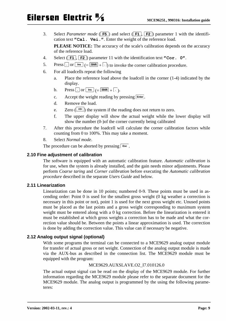
3. Select Parameter mode ( F5 ) and select ( F1 , F2 ) parameter 1 with the identifi-cation text ”Cal. Vei.”. Enter the weight of the reference load. PLEASE NOTICE: The accuracy of the scale's calibration depends on the accuracy of the reference load.
4. Select ( F1 , F2 ) parameter 11 with the identification text ”Cor. 0”. 5. Press . or Ins (= Shift + . ) to invoke the corner calibration procedure. 6. For all loadcells repeat the following
a. Place the reference load above the loadcell in the corner (1-4) indicated by the display.
b. Press . or Ins (= Shift + . ). c. Accept the weight reading by pressing Enter . d. Remove the load. e. Zero ( >0< ) the system if the reading does not return to zero. f. The upper display will show the actual weight while the lower display will
show the number (0-)of the corner currently being calibrated 7. After this procedure the loadcell will calculate the corner calibration factors while
counting from 0 to 100%. This may take a moment. 8. Select Normal mode. The procedure can be aborted by pressing Esc .
2.10 Fine adjustment of calibration The software is equipped with an automatic calibration feature. Automatic calibration is for use, when the system is already installed, and the gain needs minor adjustments. Please perform Coarse taring and Corner calibration before executing the Automatic calibration procedure described in the separate Users Guide and below.
2.11 Linearization Linearization can be done in 10 points; numbered 0-9. These points must be used in as-cending order: Point 0 is used for the smallest gross weight (0 kg weather a correction is necessary in this point or not), point 1 is used for the next gross weight etc. Unused points must be placed as the last points and a gross weight corresponding to maximum system weight must be entered along with a 0 kg correction. Before the linearization is entered it must be established at which gross weights a correction has to be made and what the cor-rection value should be. Between the points a linear approximation is used. The correction is done by adding the correction value. This value can if necessary be negative.
2.12 Analog output signal (optional) With some programs the terminal can be connected to a MCE9629 analog output module for transfer of actual gross or net weight. Connection of the analog output module is made via the AUX-bus as described in the connection list. The MCE9629 module must be equipped with the program:
MCE9629.AUXSLAVE.O2_I7.010126.0 The actual output signal can be read on the display of the MCE9629 module. For further information regarding the MCE9629 module please refer to the separate document for the MCE9629 module. The analog output is programmed by the using the following parame-teres:
Version: 2002-03-11, rev.: 4 Page: 9

MCE9625L, 990316: Installation guide
Analog output parameters (optional) Group Parameter No Display tekst MCE9629 Parameters
Analog Display Type (mA/Volt) 130 An.diSP
Analog Test Mode (Off/On) 131 An.tESt
Analog Output Mode (Gross/Net) 132 An.tyPE
Load for maximum analog output 133 An.LoAd
Analog Output Value 134 An.Out
AUX communi-cation
Status for AUX-communications unit no. X 150-151 dEv.0–dEv.1
During connection of the MCE9629 module the following must be indicated/chosen:
• the desired analog display reading. The analog output/display type is entered in parameter 130 (”An.diSP”). "AmP" / "Volt" is selected depending on the con-figuration of the MCE9629 module.
• the desired weight (gross or net) that the analog output signal should follow. The weight that the signal should follow is entered in parameter 132 (”An.tyPE”).
• the desired weight value that should result in maximum analog output signal. The weight resulting in maximum analog signal is entered in parameter 133 (”An.LoAd”).
It is always possible to read the value that is transferred to the MCE9629 analog module no matter if analog test mode is enabled or not (see below). The transferred value (in mA or in Volt) can be read in parameter 134 (”An.Out.”). It is possible to test the analog output connection. This is done in parameter 131 (”An.tESt”) by selecting ”On” and thereafter entering the desired output signal in pa-rameter 134 (”An.Out.”). The output signal is normally overwritten by the signal corre-sponding to the actual load; but NOT if the analog test mode is enabled. Remember to dis-able analog test mode again by selecting ”OFF”. Please note that MCE9629 analog modules configured as current modules, can go below 4.00 mA, if the selected weight becomes negative (since 0 kg equals 4.00 mA).
2.13 AUX communication It is possible to read the status for those units that are connected to the AUX-bus, and that the MCE9625 terminal is communicating with. Status of a unit X can be read in parameter 150+X (”dEv. X”). During display of status for a given unit ”96xx.ss” is shown in the big display. Here ”96xx” indicates the type of unit, while ”ss” indicates the actual status of the unit. Depending of the actual status the following status codes can appear as 2 digit hexadecimal numbers:
Status Cause 80 Unit NOT detected since power-up. 40 Unit detected but communication error with unit. 20 Unit detected but number of received data bytes does not match the
expected. 00 Unit detected and communication with this unit is error free.
Version: 2002-03-11, rev.: 4 Page: 10
MCE9625L, 990316: Installation guide
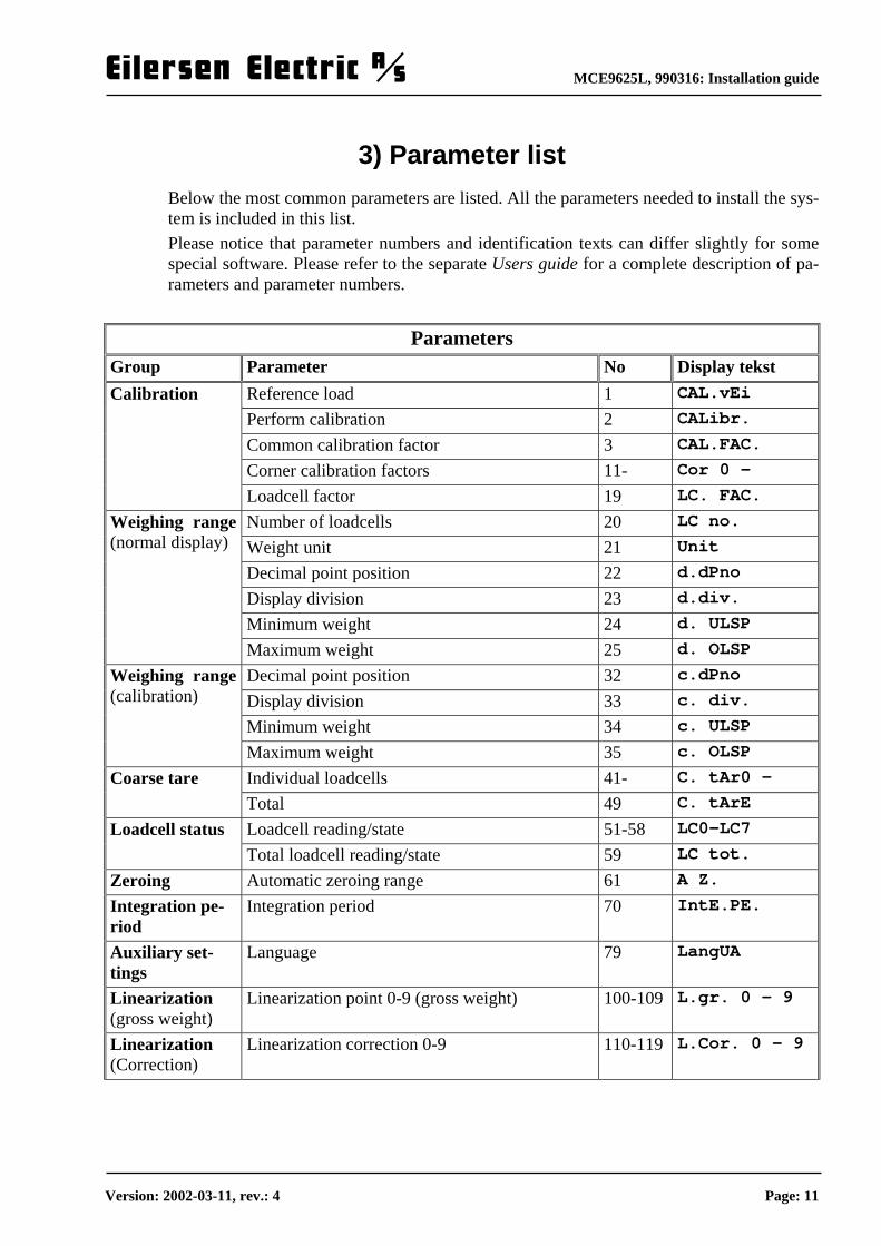
3) Parameter list Below the most common parameters are listed. All the parameters needed to install the sys-tem is included in this list. Please notice that parameter numbers and identification texts can differ slightly for some special software. Please refer to the separate Users guide for a complete description of pa-rameters and parameter numbers.
Parameters Group Parameter No Display tekst
Reference load 1 CAL.vEi
Perform calibration 2 CALibr.
Common calibration factor 3 CAL.FAC.
Corner calibration factors 11- Cor 0 -
Calibration
Loadcell factor 19 LC. FAC.
Number of loadcells 20 LC no.
Weight unit 21 Unit
Decimal point position 22 d.dPno
Display division 23 d.div.
Minimum weight 24 d. ULSP
Weighing range (normal display)
Maximum weight 25 d. OLSP
Decimal point position 32 c.dPno
Display division 33 c. div.
Minimum weight 34 c. ULSP
Weighing range (calibration)
Maximum weight 35 c. OLSP
Individual loadcells 41- C. tAr0 - Coarse tare Total 49 C. tArE
Loadcell reading/state 51-58 LC0-LC7 Loadcell status Total loadcell reading/state 59 LC tot.
Zeroing Automatic zeroing range 61 A Z.
Integration pe-riod
Integration period 70 IntE.PE.
Auxiliary set-tings
Language 79 LangUA
Linearization (gross weight)
Linearization point 0-9 (gross weight) 100-109 L.gr. 0 - 9
Linearization (Correction)
Linearization correction 0-9 110-119 L.Cor. 0 - 9
Version: 2002-03-11, rev.: 4 Page: 11

MCE9625L, 990316: Installation guide
MCE9629 Parameters
Analog Display Type (mA/Volt) 130 An.diSP
Analog Test Mode (Off/On) 131 An.tESt
Analog Output Mode (Gross/Net) 132 An.tyPE
Load for maximum analog output 133 An.LoAd
Analog Output Value 134 An.Out
AUX communi-cation
Status for AUX-communications unit no. X 150-151 dEv.0–dEv.1
Please notice that not all programs can be used with a MCE9629 analog module. Please check the separate Users guide for a detailed explanation of the features of the individual programs.
Version: 2002-03-11, rev.: 4 Page: 12
MCE9625L, 990316: Installation guide
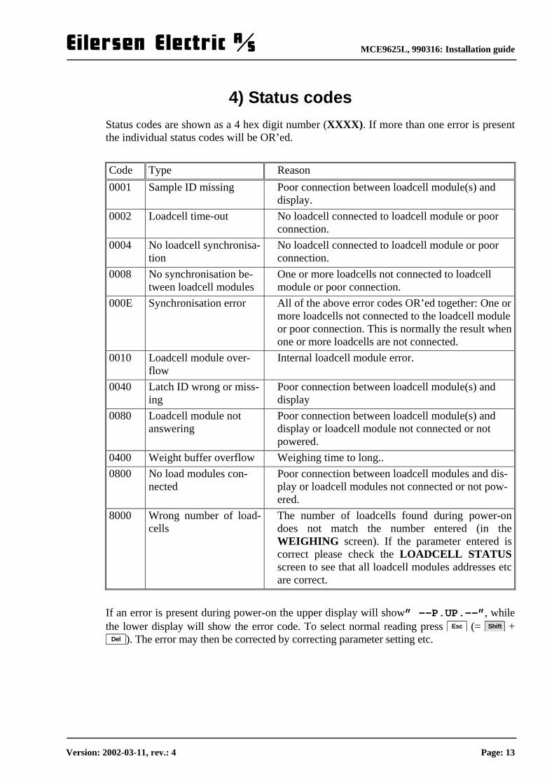
4) Status codes Status codes are shown as a 4 hex digit number (XXXX). If more than one error is present the individual status codes will be OR’ed. Code Type Reason 0001 Sample ID missing Poor connection between loadcell module(s) and
display. 0002 Loadcell time-out No loadcell connected to loadcell module or poor
connection. 0004 No loadcell synchronisa-
tion No loadcell connected to loadcell module or poor connection.
0008 No synchronisation be-tween loadcell modules
One or more loadcells not connected to loadcell module or poor connection.
000E Synchronisation error All of the above error codes OR’ed together: One or more loadcells not connected to the loadcell module or poor connection. This is normally the result when one or more loadcells are not connected.
0010 Loadcell module over-flow
Internal loadcell module error.
0040 Latch ID wrong or miss-ing
Poor connection between loadcell module(s) and display
0080 Loadcell module not answering
Poor connection between loadcell module(s) and display or loadcell module not connected or not powered.
0400 Weight buffer overflow Weighing time to long.. 0800 No load modules con-
nected Poor connection between loadcell modules and dis-play or loadcell modules not connected or not pow-ered.
8000 Wrong number of load-cells
The number of loadcells found during power-on does not match the number entered (in the WEIGHING screen). If the parameter entered is correct please check the LOADCELL STATUSscreen to see that all loadcell modules addresses etc are correct.
If an error is present during power-on the upper display will show” --P.UP.--”, while the lower display will show the error code. To select normal reading press Esc (= Shift +
Del ). The error may then be corrected by correcting parameter setting etc.
Version: 2002-03-11, rev.: 4 Page: 13

MCE9625L, 990316: Installation guide
5) Operator panel
5.1 Introduction Please note that the use of keys and LED’s stated in this section may differ slightly for some special software. Please refer to the separate Users Guide to see the specific use of all keys and LED’s. The display contains to six digit LED displays and a number of LED’s and keys. The upper display is mainly used to show the actual weight and keyed in values while the lower dis-play is used to show texts identifying the value in the upper display. The LED’s are named after the key nearby and are used to indicate the following conditions: F5: Parameters are shown and can be changed. Please refer to the separate Users Guide to see how the other LED’s are uses. The keys are used as follows: 0 - 9 : Keying of numbers. . : Decimal point. Used during decimal number entry.
+- : Initiates the entry of a negative number. Enter : Accepts the keyed in number. Del : Deletes the last digit entered. Esc = Shift + Del :
Abort the entry and use the old value. F1 - F10 : Function keys ( F6 - F10 is reached by holding down Shift while pressing
F1 - F5 ) Function dependant of mode. Stop : Return to the prior mode.
= Shift + 8 : Select prior.
= Shift + 2 : Select next.
>0< : Zero the weight reading. AT : Taring (Zero the net weight).
This is the general function of the keys Please note that the use of keys stated in this sec-tion may differ slightly for some special software. Please refer to the separate Users Guide to see the specific use of all keys.
5.2 Normal reading Please note that the use of keys and the display readings stated in this section may differ slightly for some special software. Please refer to the separate Users Guide to see the spe-cific use of all keys and the display readings. While Normal mode is selected the upper display will show the weight while the lower display will indicate whether the gross or the net weight is shown.
Version: 2002-03-11, rev.: 4 Page: 14
MCE9625L, 990316: Installation guide
If the load is above the weighing range the display will show ”OL”, if the load is below the weighing range the display will show ”UL”. The weighing range is selected with the Maximum weight and Minimum weight parameters. If an error condition is present a status code will be shown: ”XXXX”. Please refer to the Status code section for further details on the individual error codes. The keys are used as follows:
>0< Zeroes the gross weight and select gross weight reading. The scale can only be zeroed when the load is within certain limits: The global zeroing range. If the load is outside these limits the display will show an error code ”ZEro UL” or ”ZEro OL” when the load is below or above the zeroing range when >0< is pressed. When the load is within the zeroing range the display will read ”ZEro donE”.
AT Taring. The net weight is zeroed and net weight reading is selected. +- Toggles between gross and net weight reading. F5 Selects Parameter mode. Parameter mode is used to inspect and change the
parameters. Please note that the use of keys and the display readings stated in this section may differ slightly for some special software. Please refer to the separate Users Guide to see the spe-cific use of all keys and the display readings.
5.3 Parameters Please see above for a complete list of all parameters. Most parameters can be keyed in. When Parameter mode is selected the display will show parameters continuously. Parame-ter mode is selected by pressing F5 . When Normal mode is selected parameters can be changed and displayed shortly if the parameter number is known. If the keyboard is left un-touched for 30 seconds during parameter entry Normal mode will be selected automati-cally WITHOUT any change to the actual parameter. To manually abort a parameter entry press Esc (= Shift + Del ) BEFORE Enter is pressed to accept the keyed value. During power-up the terminal will make a print of all parameters (the display will show ”Print P.UP”; please refer to the separate Users guide for channel and communication settings). This can also be done by pressing Print while Parameter mode is selected.
5.3.1 Parameters in Normal mode During Normal mode parameter values can be read by pressing Enter . When this is done the upper display will be blanked and the lower display will be ready to accept a parameter number entry, like this:
“ “ “Par._ “
Key in the desired parameter number and press Enter . The upper display will now show the parameter value while the lower display will show the parameter identification text, e.g. like this:
“524288“ “CAL.FAC.“
After approximately 3 seconds the weight reading will be re-established. It is also possible to change the parameter values when Normal mode is selected. This is done by simply starting to enter the new value. When the digits are keyed the upper display will show the keyed in value while the lower display will indicate that a new parameter value is being entered, like this:
“524_ “ “Par. “
Version: 2002-03-11, rev.: 4 Page: 15

MCE9625L, 990316: Installation guide
When the entry of the new value is complete, press Enter to accept the value. The upper display will now show the keyed in value while the lower display will be ready to accept a parameter number entry, like this:
“524388“ “Par._ “
Now enter the desired parameter number and press Enter . The upper display will now show the new parameter value while the lower display will show the parameter identification text, like this:
“524388“ “CAL.FAC.“
After approximately 3 seconds the weight reading will be re-established. To abort the parameter entry press Esc (= Shift + Del ) before Enter is pressed the second time to accept the parameter number. Please notice that not all parameters can be changed this way. Some parameters (e.g. coarse taring and calibration) has to read the loadcell signal while other parameters only can be switch among a set of pre pre-programmed values. This can only be done when Pa-rameter mode is selected. Furthermore a range of parameters are read-only and cannot be changed at all (e.g. loadcell signals).
5.3.2 Parameters in Parameter mode The procedures described above used to inspect and change parameter values can be used when Parameter mode is selected as well. However when Parameter mode is selected it is not longer necessary to know the parameter number to inspect and change parameter val-ues. When Parameter mode is selected the most recent used parameter is display continu-ously. The upper display will show the parameter value while the lower display will show the parameter identification text or the parameter number, like this:
“524288“ “CAL.FAC.“
Here the following keys can be used: 0 - 9 , +- : Start entering a new parameter value. +- : Starts the entry of a negative num-
ber. = Shift + 4 and = Shift + 8 and
F1 : Select the previous parameter. = Shift + 6 and
= Shift + 2 and F2 : Select the next parameter. F5 : Switches between display of the parameter number or the parameter identi-
fication text in the lower display. Ins = Shift + . and . Read the new parameter value from the loadcells or select the next possible
value. Print Print out all parameters as during power-up (please refer to the separate Us-
ers guide for channel and communication settings). Stop : Select Normal mode.
Version: 2002-03-11, rev.: 4 Page: 16

MCE9625L, 990316: Installation guide
When the desired parameter is selected the value can be changed simply by entering the new value (if a negative value has to be entered +- has to be pressed first). During the entry the upper display will show the keyed in value while the lower display will show the pa-rameter identification text or the parameter number, like this:
“524_ “ “CAL.FAC.“
When the new value is complete press Enter to accept the entry. To abort the entry press Esc (= Shift + Del ) before Enter is pressed to accept the value. For some parameters (e.g. decimal point position) it is not possible to key in a new value. Here it is possible to select from a set of pre-programmed values. To selected the next pos-sible value press . or Ins (= Shift + . ). Please notice that the procedures described above cannot be used for all parameters. Some parameters (e.g. coarse tare and calibration) has to read the actual loadcell signals. To do this select the desired parameter and press . or Ins (= Shift + . ). The upper display will now show the actual loadcell reading while the lower display will be asking for confirma-tion before the value is actually read:
“ 5.100“ “SurE?“
To confirm the value press Enter . To abort the reading press Del or Esc (= Shift + Del ). Please notice that a range of parameters are read-only and cannot be changed at all (e.g. loadcell signals).
5.4 Automatic zeroing The terminal performs an automatic zeroing when the following conditions are met:
• The gross weight are within the automatic zeroing range and steady. • The new zero is within the global zeroing range
There is not performed a full zeroing whenever a new weight reading is calculated. Instead the new zero is calculated from the old zero and the actual gross weight in the ratio 3:1 (new zero = (3*old zero + weight reading)/4). The automatic zeroing range is entered as parameter 61 (”A Z”).
5.5 Calibration The system can be calibrated with a reference load by performing this procedure: 1. The system has to be coarse tared and corner calibrated (where corner calibration ap-
plies) as described above. If there are any doubt please check at least the corner cali-bration with a reference load.
2. Zero the empty system by pressing >0< when Normal mode is selected. 3. Select Parameter mode ( F5 ) and select parameter 1 (”CAL.vEi.”), reference
load, and enter the weight of the load. Please notice that the precision of the calibra-tion is directly dependant on the size and precision of the load The reference load must be chosen so that is it not smaller than the maximum load normally used on the system.
4. Select parameter 2 (”CALibr.”) and place the reference load on the system. The weight reading in the upper display will now be within +/-10% of the correct load. If not so please check the mechanical an electrical connections as described above. Please check the weighing range parameters as well.
Version: 2002-03-11, rev.: 4 Page: 17

MCE9625L, 990316: Installation guide
5. Press . or Ins (= Shift + . ) to calibrate. The upper display will now show the ac-tual weight reading while the lower display will ask for confirmation, like this:
“ 5.000“ “Sure?“
To confirm the calibration press Enter . To abort the calibration press Del or Esc (= Shift + Del ).
6. Select Normal mode ( Stop ).
5.5.1 Reference load The size of the reference load used for calibration and corner calibration (same parameter) must be entered prior to the calibration (or corner calibration). This is done by selecting Parameter mode ( F5 ), parameter 1 (”CAL.vEi.”) and then enter the value.
5.5.2 Calibration factors The terminal permits reading and changing of the internal calibration factors. This feature is used to re-establish a prior calibration is the calibration factors are known. The terminal holds a common calibration factor, parameter 3 (”CAL.FAC.”), and a corner calibration factor for each loadcell/corner, parameter 11 (”Cor. 0”) and forward.
5.6 Loadcell status The terminal has a feature that enables the user to see the reading and status code of the in-dividual loadcells (according to the section Status codes). This is done by selecting pa-rameter 51-58 (”LC0”-”LC7”) for loadcell 1-8 (addresses 0-7). If no errors are present the loadcell reading is shown otherwise the status code is shown. Parameter 59 (”LC.tot.”) shows the total summed reading for all connected loadcells. During power-up the terminal will print all parameters (please refer to the separate Users guide for chan-nel and communication settings) while the display shows ”Print P.UP”. This can be done by pressing Print while Parameter mode is selected as well. This print contains more detailed information on the individual loadcell: Serial number, production year, capacity, ex-ponent etc.
5.7 Integration period It is possible to select the measuring time (integration period) . This is done by selecting parameter mode ( F5 ), parameter 70 (”IntE.PE.”) and then enter the desired time in milliseconds. A smaller values will give a fast update of the display weight reading while a larger value will give a more steady reading. The default value is 400 ms.
5.8 Language It is possible to select the display language to be English or Danish. This is done by select-ing Parameter mode ( F5 ), parameter 79 (”LAn”) and select a new setting by pressing . or Ins (= Shift + . ). Please notice that in this installation guide it is assumed that English is selected.
Version: 2002-03-11, rev.: 4 Page: 18

MCE9625L, 990316: Installation guide
6) Connections The connection shown below applies to the terminal block on the back of the MCE9625. If the system is connected via a motherboard please refer to the documentation for this moth-erboard. Please notice that the different groups (RS232, DIG.OUT. etc.) must normally NOT be powered from the terminals on the MCE9625, when the connection is made via a motherboard; the groups will then be powered from the motherboard. POWER No. Function Connection + +24VDC Supply - 0VDC Supply
DIG.OUT No. Function Connection 1 Output 1 2 Output 2 3 Output 3 4 Common +24VDC
DIG.IN No. Function Connection 1 Input 1 (closing switch to +24VDC) 2 Input 2 (closing switch to +24VDC) 3 Input 3 (closing switch to +24VDC) 4 Common 0VDC
RS232 No. Function Connection 1 Supply +24VDC Supply 2 Txd-0 (RXD) 3 Rxd-0 (TXD) 4 Txd-1 (RXD) 5 Rxd-1 (TXD) 6 Supply 0VDC Supply (and GND)
Version: 2002-03-11, rev.: 4 Page: 19

MCE9625L, 990316: Installation guide
RS485 (Loadcells) No. Function Connection 1 Supply +24VDC Supply 2 B B Loadcells: B 3 A A Loadcells: A 4 Supply 0VDC Supply
RS485/422 No. Function Connection 1 Supply +24VDC Supply 2 R- (T-) 3 R+ (T+) 4 Supply 0VDC Supply (and GND) 5 T- (R-) 6 T+ (R+)
AUX (LED –display and external devices) No. Function Connection 1 Supply +24VDC Supply 2 B External devices: B 3 A External devices: A 4 Supply 0VDC Supply and external devices: Gnd
6.1 MCE9629 Analog output module The analog output module (MCE9629) is connected to the weighing terminal (MCE9625) via a MCE9601 module. The MCE9601 module is connected to the weighing terminal as follows:
6.1.1 MCE9601 connection Terminal ConnectionGND Not used B AUX.2 on MCE9625 terminal A AUX.3 on MCE9625 terminal GND AUX.4 on MCE9625 terminal +24V AUX.1 on MCE9625 terminal GND Not used I/O Not used
The MCE9601 module is connected to the analog module (MCE9629) via the supplied ribbon cable. In addition the following connections are available on the analog output module (MCE9629):
Version: 2002-03-11, rev.: 4 Page: 20

MCE9625L, 990316: Installation guide
6.1.2 MCE9629: J2 (digital IO) No. Function Connection 1 Input 1 Not used 2 Gnd 0VDC Not used 3 Input 2 Not used 4 24VDC (Out) Not used 5 OUT1 Not used 6 Common +24VDC Not used 7 OUT2 Not used
6.1.3 MCE9629: J4 (Analog output) No. Function Connection 1 Analog output 4-20mA / 0-10V Analog input 2 Analog return Analog return
The analog output module (MCE9629) must be equipped with the following program:
MCE9629.AUXSLAVE.O2_I7.010126.0.
and all switches (Sw1.-Sw1.4) on the MCE9629 module MUST be OFF. Please refer to the separate document for the MCE9629 module and the drawing below.
Version: 2002-03-11, rev.: 4 Page: 21

MCE9625L, 990316: Installation guide
6.1.4 Connection of MCE9629 Analog module (and loadcells):
MCE9610
Eilersen Electric
MCE9610MCE9610 MCE9610
Version: 2002-03-11, rev.: 4 Page: 22

MCE9625L, 990316: Installation guide
7) Download of new software to MCE9625
7.1 Download 1. Connect a RS232 cable from the PC COM port to one of the MCE9525 RS232 ports.
Any COM-port can be used, but the batch-file on the download disk defaults to COM1. The COM-port can be change in the batch file (DL.BAT), replace '-c1' (for COM1) with e.g. '-c2' (for COM2). The cable must apply to this standard:
Download cable for MCE9625 PC COMx
(Uses either 9 or 25 pin SUB-D con-nector)
MCE9625 (RS232 on block) (Use either RS232.0 or RS232.1)
9 pin connector 25 pin connector RS232.0 RS232.1 PC.RxD Pin 2 Pin 3 Terminal 2 *) Terminal 4 *) PC.TxD Pin 3 Pin 2 Terminal 3 *) Terminal 5 *) GND Pin 5 Pin 7 Terminal 6 Terminal 6
*) Either RS232.0 or RS232.1 can be used. However RxD and TxD for the same port
MUST be used. All other connections to the RS232 port used for download must be disconnected. Any kind of equipment connection to the RS232 port not used for download must
be switch off. If this is not possible it must be disconnected. 2. Power on the MCE9625. If any doubt that the MCE9625 RS232 port is powered cor-
rectly (The RS232 has a separate supply) the voltage between terminal 1 and 6 on the MCE9625 RS232 section must be checked. The voltage on terminal 6 must be +24VDC (+/-20%) when terminal 1 is used as reference. If not so a +24VDC supply must be connected as described above.
3. When the PC is running the download disk must be inserted. Please observed that the disk MUST NOT be write protected during download as a temporary file is written to the disk.
4. If Microsoft Windows 95/98 is used a DOS box must be started by selecting "MS-DOS-prompt" in the “Start” menu.
5. Select the floppy drive (A: or B:) by keying: "A: <ENTER>"
or "B: <ENTER>".
6. Run the batch file 'DL.BAT' by keying: "DL <ENTER>"
After a copyright notice the screen will display: Connecting....... etc.
When using a floppy disp it may take 1-2 minutes before this happens. 7. Now download by switching the MCE9625 off shortly and then back on or press
SHIFT, STOP and DEL simultaneously until the MCE9625 resets.
Version: 2002-03-11, rev.: 4 Page: 23

MCE9625L, 990316: Installation guide
8. When the PC has made a connection to the MCE9625 the "Connecting" message will disappear and the PC will download the program. After this the PC program will stop and the MCE9625 will reboot with the new program. Download will take less than 5 minutes. Otherwise restart the procedure above.
The software version must be checked in the display when the MCE9625 reboots to assure that the download procedure was performed correct.
7.2 Errors If this procedure is not working it is likely to be cause by one of these errors: 9. Cable error. Recheck the connections and try to switch TxD and RxD. Check the
PC.TXD signal. The DC voltage must be between -3 and -25 VDC when GND is used as reference when download is not started. If not so the cable or the COM port is faulty.
10. The wrong COM port is used on the PC 11. No power supply for the MCE9625 RS232 block. Check this as described above.
Version: 2002-03-11, rev.: 4 Page: 24