Embed Size (px)
DESCRIPTION
micro pro
Citation preview
Week 2The 80x86 Microprocessor
Architecture
2
Brief History of the 80x86 Family
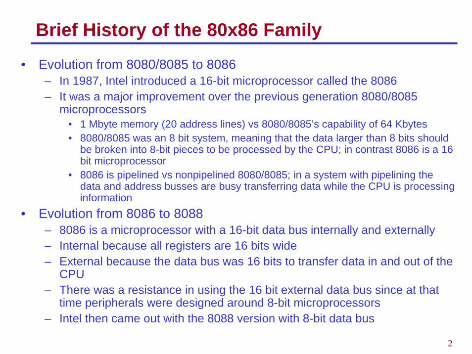
• Evolution from 8080/8085 to 8086– In 1987, Intel introduced a 16-bit microprocessor called the 8086– It was a major improvement over the previous generation 8080/8085
microprocessors• 1 Mbyte memory (20 address lines) vs 8080/8085’s capability of 64 Kbytes• 8080/8085 was an 8 bit system, meaning that the data larger than 8 bits should
be broken into 8-bit pieces to be processed by the CPU; in contrast 8086 is a 16 bit microprocessor
• 8086 is pipelined vs nonpipelined 8080/8085; in a system with pipelining the data and address busses are busy transferring data while the CPU is processing information
• Evolution from 8086 to 8088– 8086 is a microprocessor with a 16-bit data bus internally and externally– Internal because all registers are 16 bits wide– External because the data bus was 16 bits to transfer data in and out of the
CPU– There was a resistance in using the 16 bit external data bus since at that
time peripherals were designed around 8-bit microprocessors– Intel then came out with the 8088 version with 8-bit data bus
3
Brief History - Continued
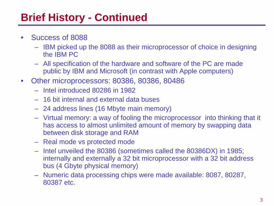
• Success of 8088– IBM picked up the 8088 as their microprocessor of choice in designing
the IBM PC– All specification of the hardware and software of the PC are made
public by IBM and Microsoft (in contrast with Apple computers)• Other microprocessors: 80386, 80386, 80486
– Intel introduced 80286 in 1982– 16 bit internal and external data buses– 24 address lines (16 Mbyte main memory)– Virtual memory: a way of fooling the microprocessor into thinking that it
has access to almost unlimited amount of memory by swapping databetween disk storage and RAM
– Real mode vs protected mode– Intel unveiled the 80386 (sometimes called the 80386DX) in 1985;
internally and externally a 32 bit microprocessor with a 32 bit address bus (4 Gbyte physical memory)
– Numeric data processing chips were made available: 8087, 80287, 80387 etc.
4
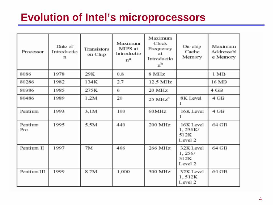
Evolution of Intel’s microprocessors
5
Virtual 8086 Mode
• Real Mode– Only one program can be run one time– All of the protection and memory management functions are turned off– Memory space is limited to 1MB
• Virtual 8086 Mode– The 386 hands each real mode program its own 1MB chunk of memory– Multiple 8086 programs to be run simultaneously but protected from
each other (multiple MSDOS prompts)– Due to time sharing, the response becomes much slower as each new
program is launched– The 386 can be operated in Protected Mode and Virtual 8086 mode at
the same time.– Because each 8086 task is assigned the lowest privilege level, access
to programs or data in other segments is not allowed thus protecting each task.
– We’ll be using the virtual 8086 mode in the lab experiments on PCs that do have either Pentiums or 486s.
6
The 80286 and above - Modes of Operation
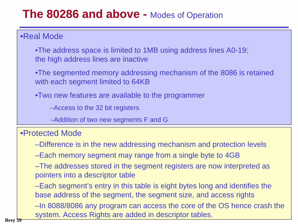
•Protected Mode–Difference is in the new addressing mechanism and protection levels–Each memory segment may range from a single byte to 4GB–The addresses stored in the segment registers are now interpreted as pointers into a descriptor table–Each segment’s entry in this table is eight bytes long and identifies the base address of the segment, the segment size, and access rights–In 8088/8086 any program can access the core of the OS hence crash the system. Access Rights are added in descriptor tables.
•Real Mode•The address space is limited to 1MB using address lines A0-19; the high address lines are inactive
•The segmented memory addressing mechanism of the 8086 is retained with each segment limited to 64KB
•Two new features are available to the programmer –Access to the 32 bit registers
–Addition of two new segments F and G
Brey 59
7
Virtual Memory
• 286 onward supported Virtual Memory Management and Protection™• Unlimited amount of main memory assumed• Two methods are used:
– Segmentation– Paging
• Both techniques involve swapping blocks of user memory with hard disk space as necessary
– If the program needs to access a block of memory that is indicated to be stored in the disk, the OS searches for an available memory block (typically using a least recently used algorithm) and swaps that block with the desired data on the hard drive
– Memory swapping is invisible to the user– Segmentation: the block size is variable ranging up to 4GB– Paging: Block sizes are always 4 KB at a time.
• A final protected mode feature is the ability to assign a privilege level to individual tasks (programs). Tasks of lower privilege level cannot access programs or data with a higher privilege level. The OS can run multiple programs each protected from each other.
Mazidi 648
8
The 8086 and 8088
• The 8086 microprocessor represents the foundation upon which allthe 80x86 family of processors have been built
• Intel has made the commitment that as new generations of microprocessors are developed, each will maintain software compatibility with this first generation part.– For example, a program designed to run on an Intel 386
microprocessor, which also runs on a Pentium, is upward compatible. • Processor model
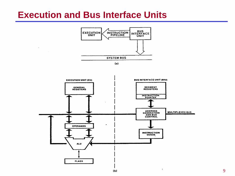
– BIU (Bus Interface Unit) provides hardware functions including generation of the memory and I/O addresses for the transfer of data between itself and the outside world
– EU (Execution Unit) receives program instruction codes and data from the BIU executes these instructions and stores the results in the general registers.
– EU has no connection to the system busses; it receives and outputs all its data through the BIU.
9
Execution and Bus Interface Units

10
Fetch and Execute Cycle
• Fetch and execute cycles overlap– BIU outputs the contents of the IP onto the address bus – Register IP is incremented by one or more than one for the next
instruction fetch– Once inside the BIU, the instruction is passed to the queue; this queue
is a first-in-first-out register sometimes likened to a pipeline– Assuming that the queue is initially empty the EU immediately draws
this instruction from the queue and begins execution– While the EU is executing this instruction, the BIU proceeds to fetch a
new instruction. • BIU will fill the queue with several new instructions before the EU is ready to
draw its next instruction– The cycle continues with the BIU filling the queue with instructions and
the EU fetching and executing these instructions
11
Pipelined Architecture
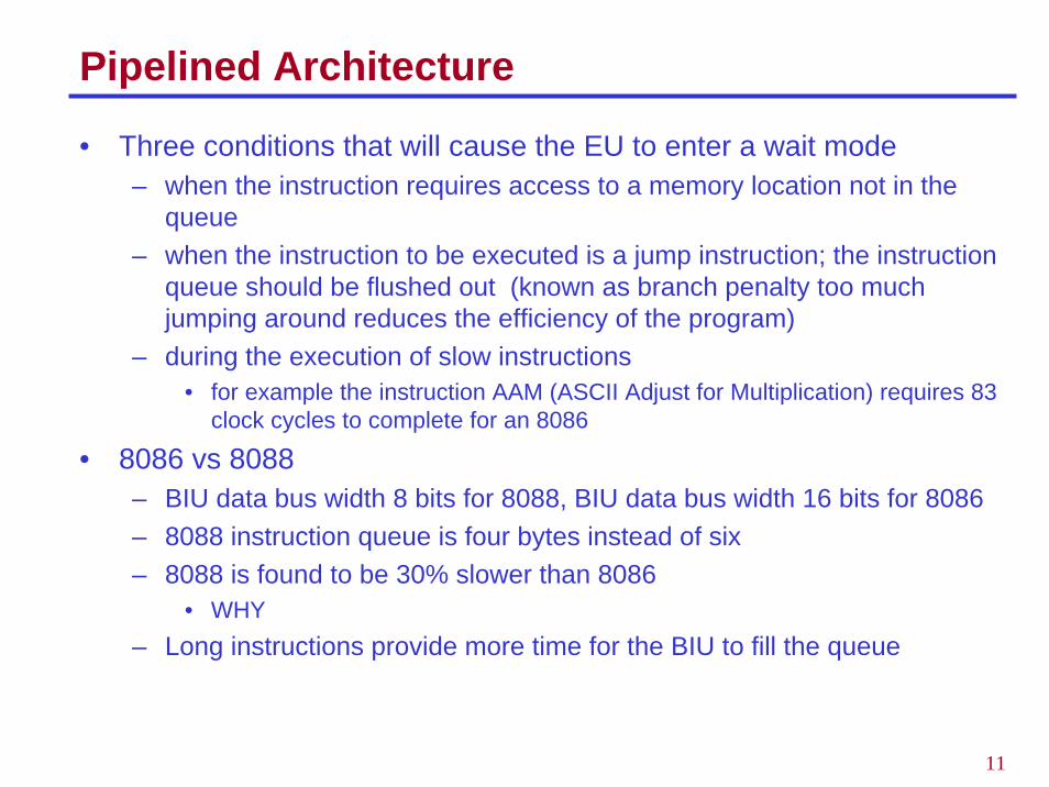
• Three conditions that will cause the EU to enter a wait mode– when the instruction requires access to a memory location not in the
queue– when the instruction to be executed is a jump instruction; the instruction
queue should be flushed out (known as branch penalty too much jumping around reduces the efficiency of the program)
– during the execution of slow instructions• for example the instruction AAM (ASCII Adjust for Multiplication) requires 83
clock cycles to complete for an 8086
• 8086 vs 8088– BIU data bus width 8 bits for 8088, BIU data bus width 16 bits for 8086– 8088 instruction queue is four bytes instead of six– 8088 is found to be 30% slower than 8086
• WHY– Long instructions provide more time for the BIU to fill the queue
12
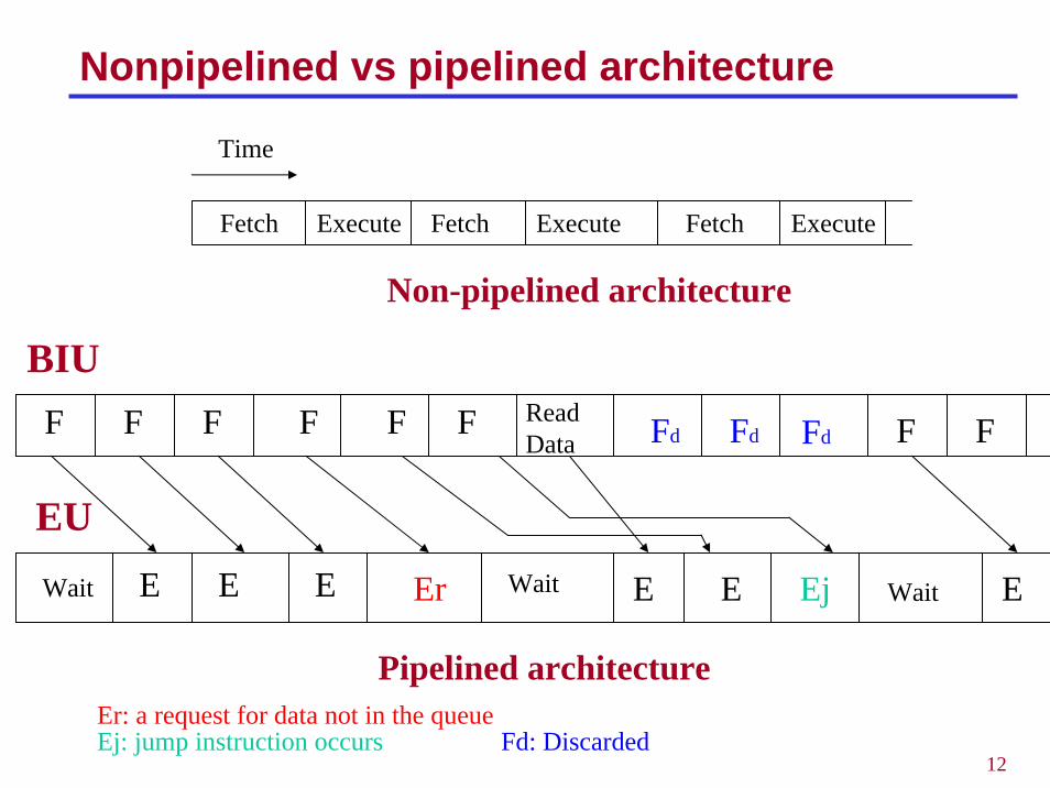
Nonpipelined vs pipelined architecture
Fetch Execute FetchFetch ExecuteExecute
Time
BIUF F F F F F
Wait E E E Er
Er: a request for data not in the queue
Read Data
Wait E E Ej
FdFdFd
EU
FF
Ej: jump instruction occurs Fd: Discarded
Wait E
Non-pipelined architecture
Pipelined architecture
13
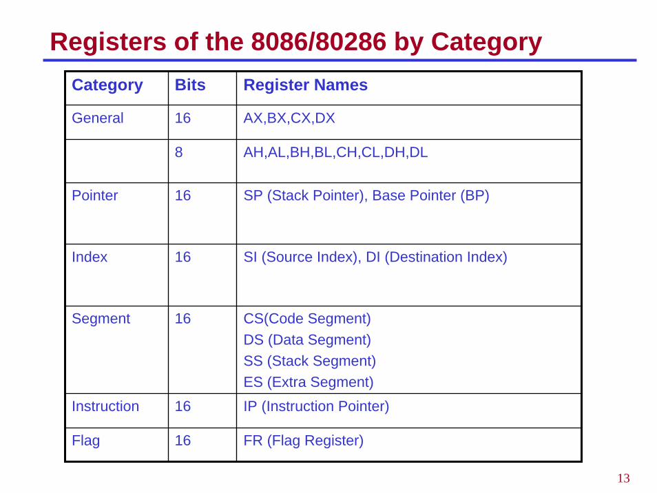
Registers of the 8086/80286 by CategoryCategory Bits Register Names
General 16 AX,BX,CX,DX
8 AH,AL,BH,BL,CH,CL,DH,DL
Pointer 16 SP (Stack Pointer), Base Pointer (BP)
Index 16 SI (Source Index), DI (Destination Index)
Segment 16 CS(Code Segment)DS (Data Segment)SS (Stack Segment)ES (Extra Segment)
Instruction 16 IP (Instruction Pointer)
Flag 16 FR (Flag Register)
14
General Purpose Registers
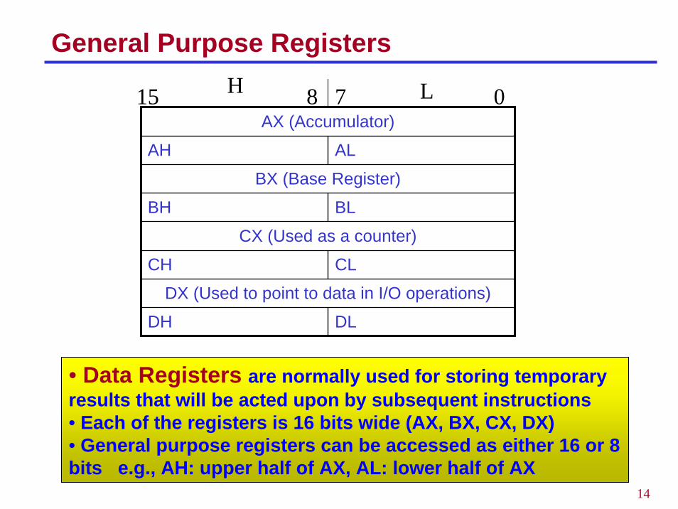
• Data Registers are normally used for storing temporary results that will be acted upon by subsequent instructions• Each of the registers is 16 bits wide (AX, BX, CX, DX)• General purpose registers can be accessed as either 16 or 8 bits e.g., AH: upper half of AX, AL: lower half of AX
AX (Accumulator)
AH AL
BX (Base Register)
BH BL
CX (Used as a counter)
CH CL
DX (Used to point to data in I/O operations)
DH DL
15 8 7 0H L
15
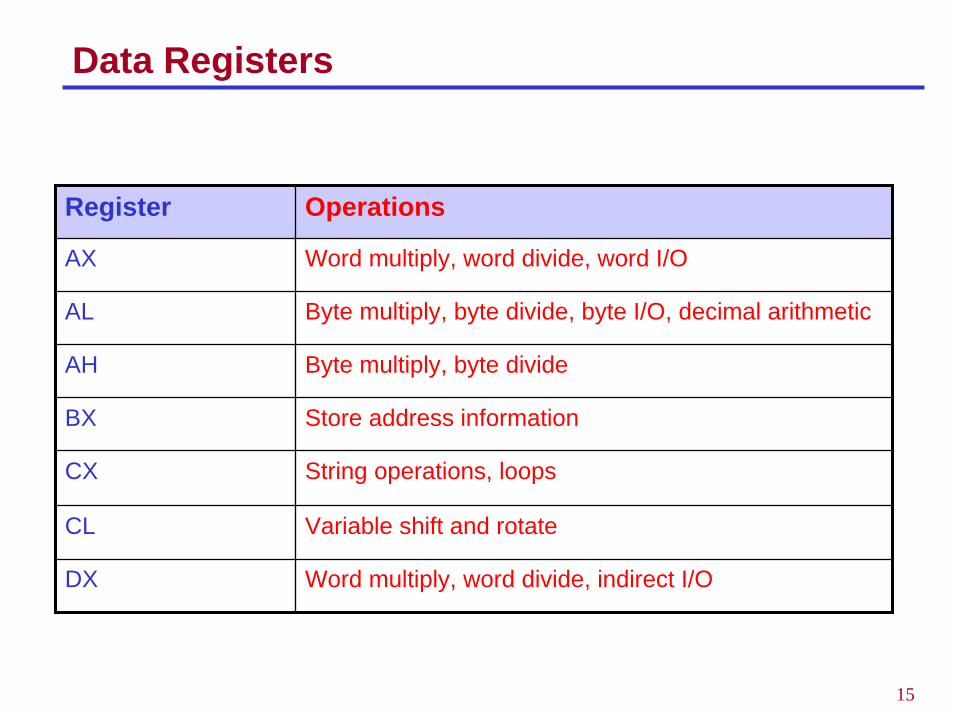
Data Registers
Register Operations
AX Word multiply, word divide, word I/O
AL Byte multiply, byte divide, byte I/O, decimal arithmetic
AH Byte multiply, byte divide
BX Store address information
CX String operations, loops
CL Variable shift and rotate
DX Word multiply, word divide, indirect I/O
16
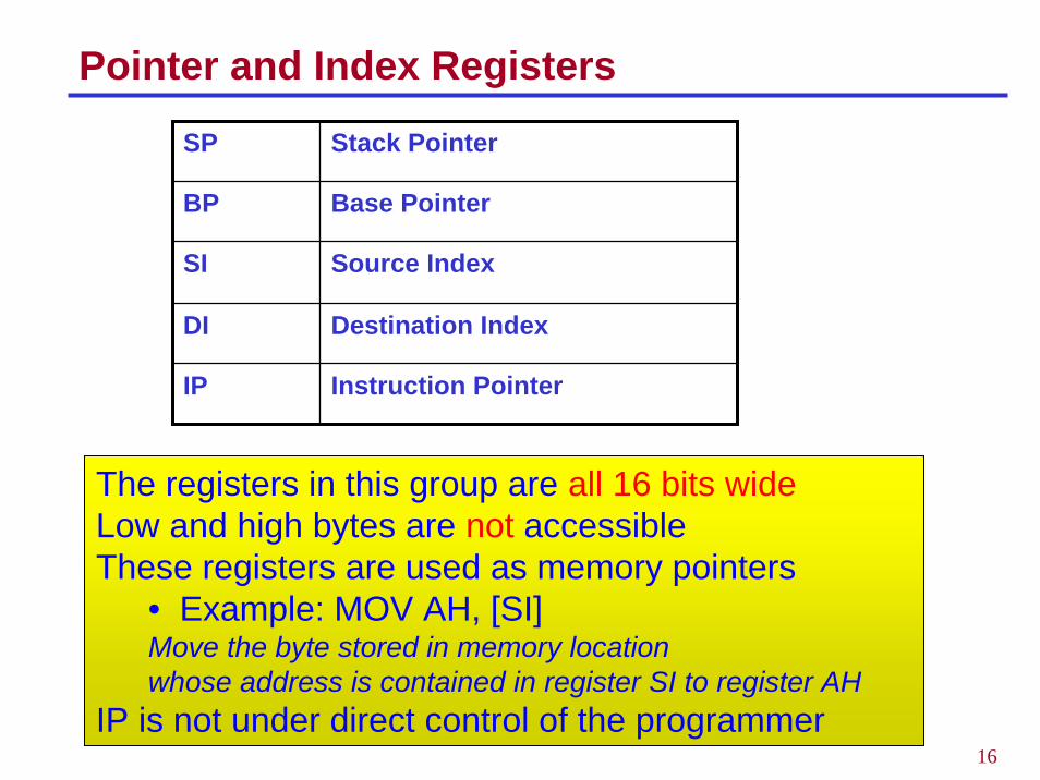
Pointer and Index Registers
The registers in this group are all 16 bits wideLow and high bytes are not accessibleThese registers are used as memory pointers
• Example: MOV AH, [SI]Move the byte stored in memory location whose address is contained in register SI to register AH
IP is not under direct control of the programmer
SP Stack Pointer
BP Base Pointer
SI Source Index
DI Destination Index
IP Instruction Pointer
17
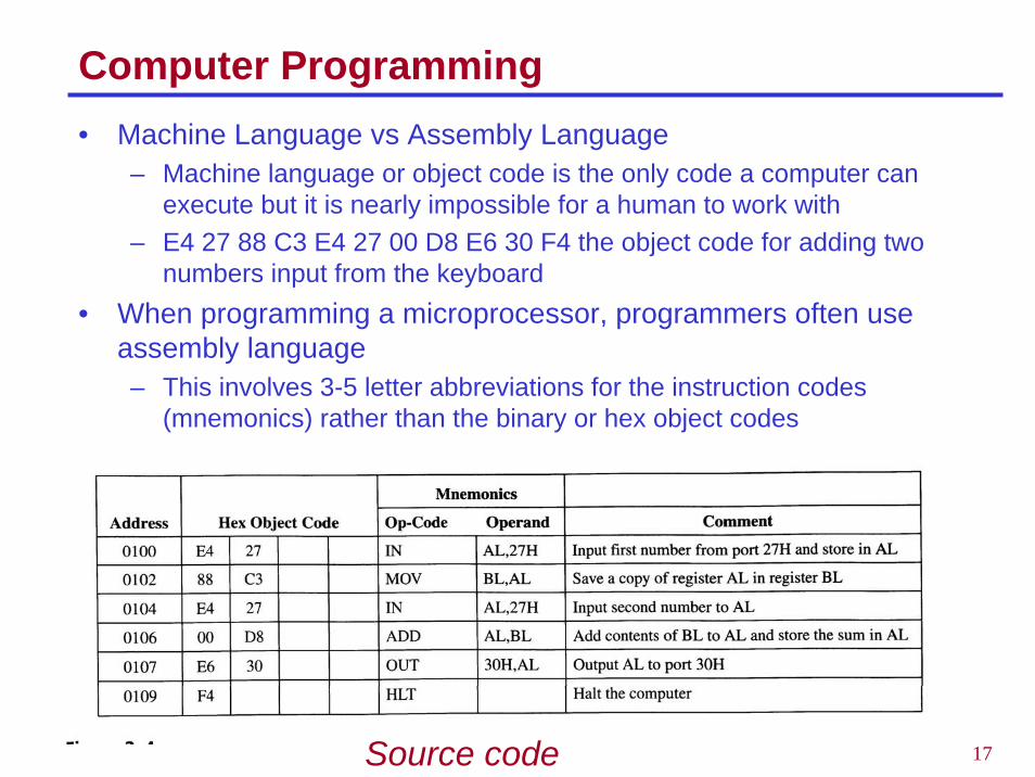
Computer Programming• Machine Language vs Assembly Language
– Machine language or object code is the only code a computer can execute but it is nearly impossible for a human to work with
– E4 27 88 C3 E4 27 00 D8 E6 30 F4 the object code for adding two numbers input from the keyboard
• When programming a microprocessor, programmers often use assembly language– This involves 3-5 letter abbreviations for the instruction codes
(mnemonics) rather than the binary or hex object codes
Source code
18
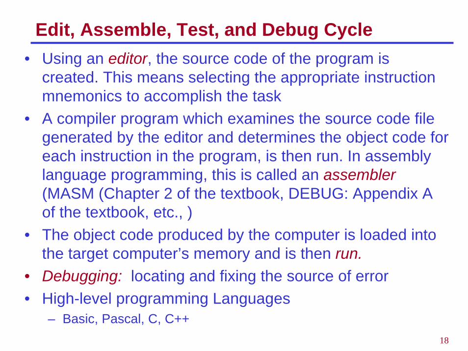
Edit, Assemble, Test, and Debug Cycle• Using an editor, the source code of the program is
created. This means selecting the appropriate instruction mnemonics to accomplish the task
• A compiler program which examines the source code file generated by the editor and determines the object code for each instruction in the program, is then run. In assembly language programming, this is called an assembler(MASM (Chapter 2 of the textbook, DEBUG: Appendix A of the textbook, etc., )
• The object code produced by the computer is loaded into the target computer’s memory and is then run.
• Debugging: locating and fixing the source of error• High-level programming Languages
– Basic, Pascal, C, C++
19
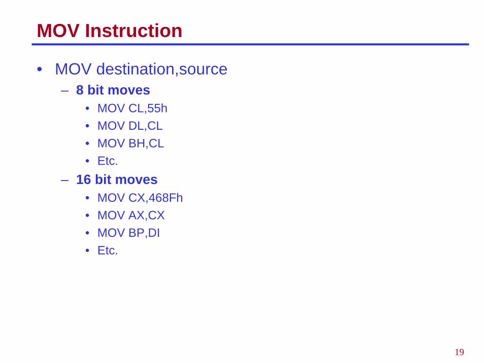
MOV Instruction
• MOV destination,source– 8 bit moves
• MOV CL,55h• MOV DL,CL• MOV BH,CL• Etc.
– 16 bit moves• MOV CX,468Fh• MOV AX,CX• MOV BP,DI• Etc.
20
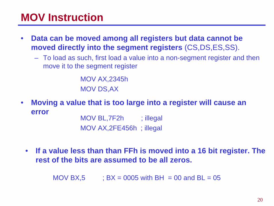
MOV Instruction
• Data can be moved among all registers but data cannot be moved directly into the segment registers (CS,DS,ES,SS).– To load as such, first load a value into a non-segment register and then
move it to the segment register
MOV AX,2345hMOV DS,AX
• Moving a value that is too large into a register will cause an error
MOV BL,7F2h ; illegalMOV AX,2FE456h ; illegal
• If a value less than than FFh is moved into a 16 bit register. The rest of the bits are assumed to be all zeros.
MOV BX,5 ; BX = 0005 with BH = 00 and BL = 05
21
MOV Instruction
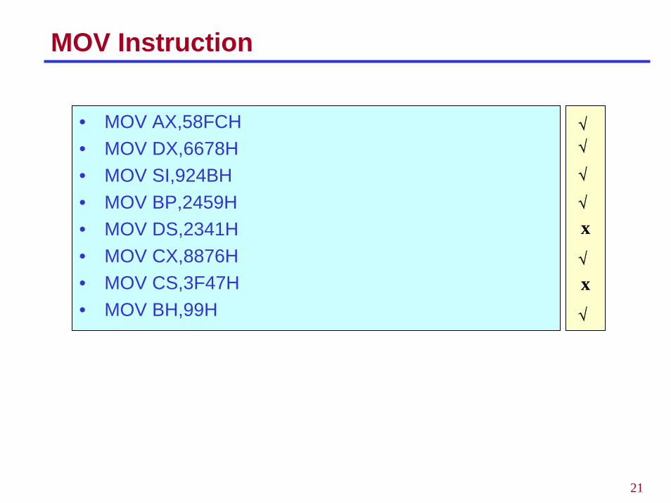
• MOV AX,58FCH• MOV DX,6678H• MOV SI,924BH• MOV BP,2459H• MOV DS,2341H• MOV CX,8876H• MOV CS,3F47H• MOV BH,99H
√
x√
√
√
√
x√
22
ADD Instruction
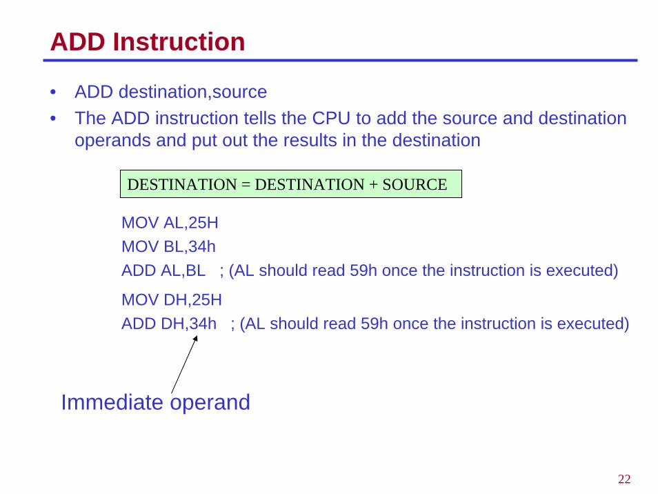
• ADD destination,source• The ADD instruction tells the CPU to add the source and destination
operands and put out the results in the destination
MOV AL,25HMOV BL,34hADD AL,BL ; (AL should read 59h once the instruction is executed)
MOV DH,25HADD DH,34h ; (AL should read 59h once the instruction is executed)
Immediate operand
DESTINATION = DESTINATION + SOURCE
23
Origin and Definition of a Segment
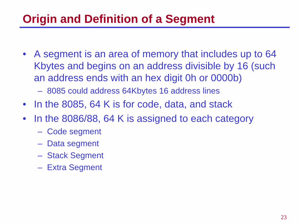
• A segment is an area of memory that includes up to 64 Kbytes and begins on an address divisible by 16 (such an address ends with an hex digit 0h or 0000b)– 8085 could address 64Kbytes 16 address lines
• In the 8085, 64 K is for code, data, and stack• In the 8086/88, 64 K is assigned to each category
– Code segment– Data segment– Stack Segment– Extra Segment
24
Advantages of Segmented Memory
• One program can work on several different sets of data. This is done by reloading register DS to a new value.
• Programs that reference logical addresses can be loaded and run anywhere in the memory: relocatable
• Segmented memory introduces extra complexity in both hardware inthat memory addresses require two registers.
• They also require complexity in software in that programs are limited to the segment size
• Programs greater than 64 KB can be run on 8086 but the software needed is more complex as it must switch to a new segment.
• Protection among segments is provided.
25
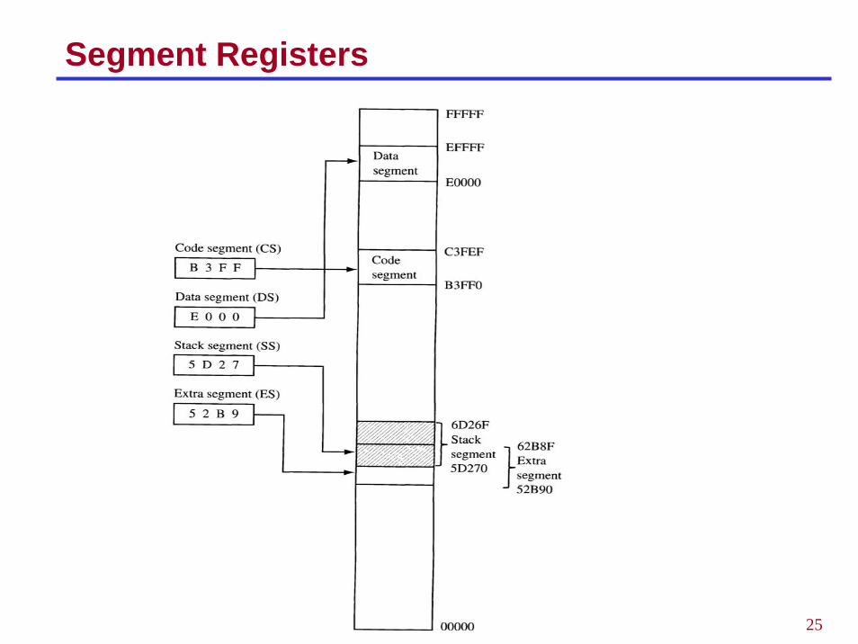
Segment Registers
26
Logical and Physical Addresses
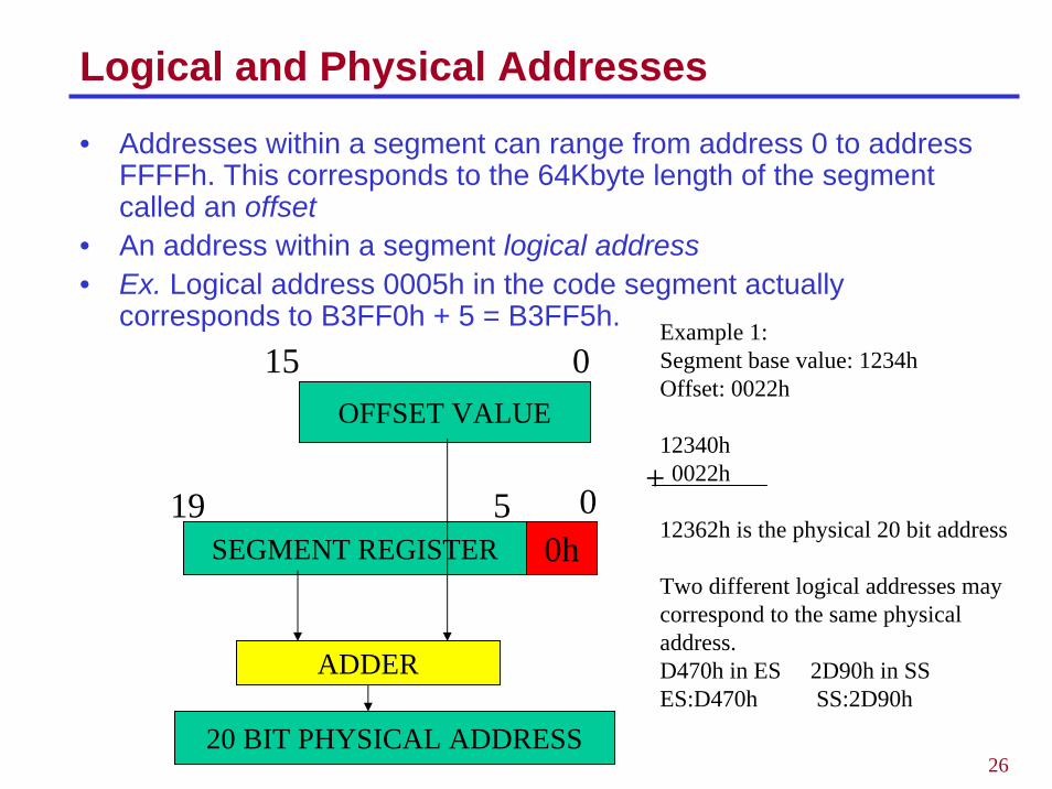
• Addresses within a segment can range from address 0 to address FFFFh. This corresponds to the 64Kbyte length of the segment called an offset
• An address within a segment logical address• Ex. Logical address 0005h in the code segment actually
corresponds to B3FF0h + 5 = B3FF5h.
OFFSET VALUE
15 0
SEGMENT REGISTER 0h0519
ADDER
20 BIT PHYSICAL ADDRESS
Example 1:Segment base value: 1234hOffset: 0022h
12340h0022h
12362h is the physical 20 bit address
Two different logical addresses may correspond to the same physical address.D470h in ES 2D90h in SS ES:D470h SS:2D90h
+
27
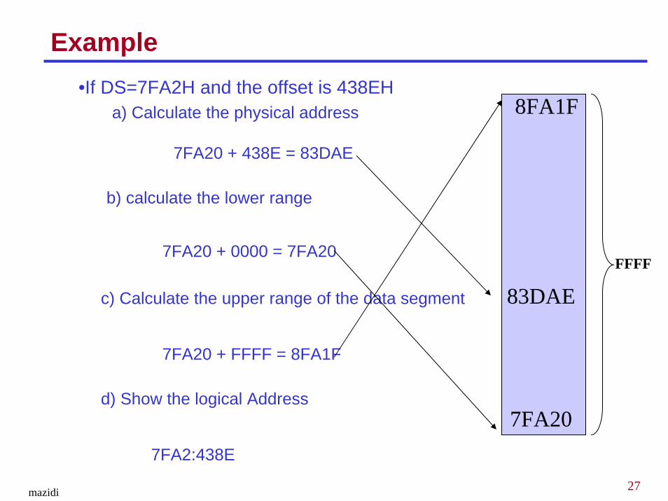
•If DS=7FA2H and the offset is 438EHa) Calculate the physical address
FFFF
b) calculate the lower range
c) Calculate the upper range of the data segment
d) Show the logical Address
7FA20 + 438E = 83DAE
Example
7FA2:438E
83DAE
7FA20 + FFFF = 8FA1F
8FA1F
7FA20 + 0000 = 7FA20
7FA20
mazidi
28
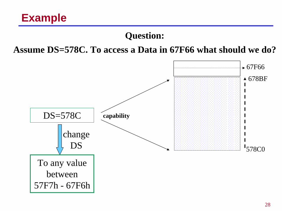
ExampleQuestion:
Assume DS=578C. To access a Data in 67F66 what should we do?
578C0
678BF
DS=578C capability
67F66
change DS
To any value between
57F7h - 67F6h

29
Code Segment
• To execute a program, the 8086 fetches the instructions (opcodes and operands) from the code segment
• The logical address is in the form CS:IP
• Example: If CS = 24F6h and IP = 634Ah, show• The logical address• The offset addressand calculate• The physical address• The lower range• The upper range

30
Logical Address vs Physical Address in the CS
CS:IP Machine Language
Mnemonics
1132:0100 B057 MOV AL,57h1132:0102 B686 MOV DH,86h1132:0104 B272 MOV DL,72h1132:0106 89D1 MOV CX,DX1132:0108 88C7 MOV BH,AL1132:010A B39F MOV BL,9F1132:010C B420 MOV AH,20h1132:010E 01D0 ADD AX,DX1132:0110 01D9 ADD CX,BX1132:0112 05351F ADD AX, 1F35h
• Show how the code resides physically in the memory

31
Data Segment
• Assume that a program is written to add 5 bytes of data 25h,12h,15h,1Fh, and 2Bh.
• One way to do it MOV AL,00hADD AL, 25hADD AL, 12hADD AL,15hADD AL,1FhADD AL,2Bh
• Data and code are mixed in the instructions here• The problem with it is if the data changes, the code must
be searched for every place the data is included and data retyped.
• It is a good idea then to set aside an area of memory strictly for data
32
Data Segment
• The data is first placed in the memory locationsDS:0200 = 25hDS:0201 = 12hDS:0202 = 15hDS:0203 = 1FhDS:0204 = 2Bh
• Then the program is written asMOV AL,0ADD AL,[0200] ; bracket means add the contents of DS:0200 to ALADD AL,[0201]ADD AL,[0202]ADD AL,[0203]ADD AL,[0204]
• If the data is stored at a different offset address, say 450 h, the program need to be rewritten
33
Data Segment
• The term pointer is used for a register holding an offset address• Use BX as a pointer
MOV AL,0MOV BX,0200hADD AL,[BX]INC BXADD AL,[BX]INC BXADD AL,[BX]INC BXADD AL,[BX]INC BXADD AL,[BX]
• If the offset address of data is to be changed, only one instructions will need to be modified
34
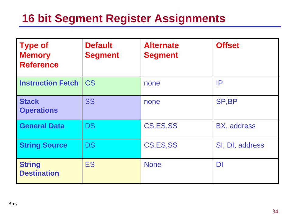
16 bit Segment Register Assignments
Type of Memory Reference
Default Segment
Alternate Segment
Offset
Instruction Fetch CS none IP
Stack Operations
SS none SP,BP
General Data DS CS,ES,SS BX, address
String Source DS CS,ES,SS SI, DI, address
String Destination
ES None DI
Brey
35
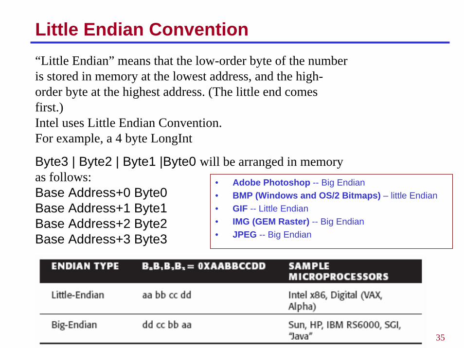
Little Endian Convention
• Adobe Photoshop -- Big Endian• BMP (Windows and OS/2 Bitmaps) – little Endian• GIF -- Little Endian• IMG (GEM Raster) -- Big Endian• JPEG -- Big Endian
“Little Endian” means that the low-order byte of the number is stored in memory at the lowest address, and the high-order byte at the highest address. (The little end comes first.) Intel uses Little Endian Convention. For example, a 4 byte LongInt
Byte3 | Byte2 | Byte1 |Byte0 will be arranged in memory as follows: Base Address+0 Byte0 Base Address+1 Byte1 Base Address+2 Byte2 Base Address+3 Byte3
36
Computer Operating Systems• What happens when the computer is first turned on?• MS-DOS
– A startup program in the BIOS (Basic Input Output System) is executed
– This program in turn accesses the master boot record on the floppy or hard disk drive
– A loader then transfers the system files IO.SYS– IO.SYS calls MSDOS.SYS. MS-DOS.SYS is basically the kernel of the
operating system. – After initializing, MS-DOS.SYS then calls the command interpreter
COMMAND.COM which is loaded into memory. This puts the DOS prompt on the screen that gives the user access to DOS’s built-in commands like DIR, COPY, VER.
37
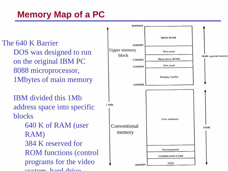
Memory Map of a PC
Conventional memory
Upper memory block
The 640 K BarrierDOS was designed to run on the original IBM PC8088 microprocessor, 1Mbytes of main memory
IBM divided this 1Mb address space into specific blocks
640 K of RAM (user RAM)384 K reserved for ROM functions (control programs for the video system hard drive
38
MS-DOS Functions and BIOS Services
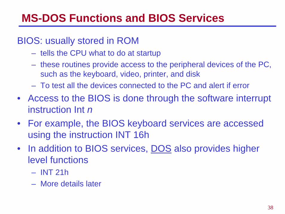
BIOS: usually stored in ROM – tells the CPU what to do at startup– these routines provide access to the peripheral devices of the PC,
such as the keyboard, video, printer, and disk– To test all the devices connected to the PC and alert if error
• Access to the BIOS is done through the software interrupt instruction Int n
• For example, the BIOS keyboard services are accessed using the instruction INT 16h
• In addition to BIOS services, DOS also provides higher level functions– INT 21h– More details later
39
More About RAM
• Memory management is one of the most important functions of the DOS operating systems and should be left to DOS
• Therefore, we do not assign any values for the DS,CS,SS registers; this is the job of DOS
• It is very important to remember that– The DS,CS, and DS values we will experiment will be different
than those used by the textbook; do not worry
40
Flag (Status) Register
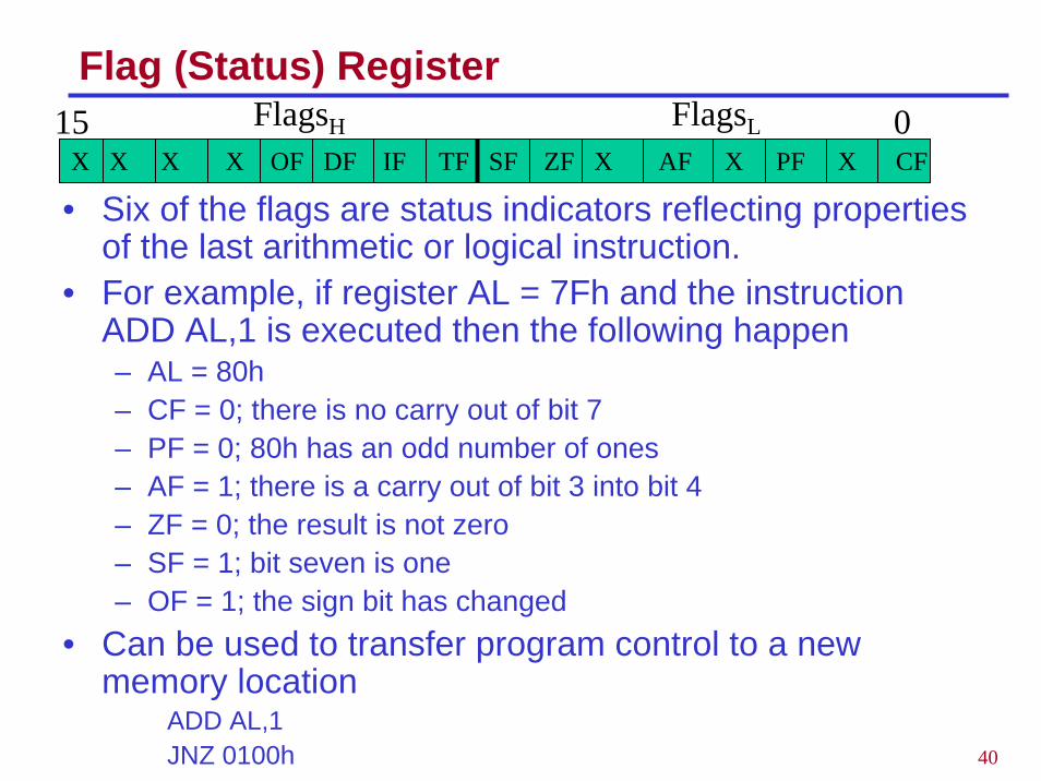
• Six of the flags are status indicators reflecting properties of the last arithmetic or logical instruction.
• For example, if register AL = 7Fh and the instruction ADD AL,1 is executed then the following happen– AL = 80h– CF = 0; there is no carry out of bit 7– PF = 0; 80h has an odd number of ones– AF = 1; there is a carry out of bit 3 into bit 4– ZF = 0; the result is not zero– SF = 1; bit seven is one– OF = 1; the sign bit has changed
• Can be used to transfer program control to a new memory location
ADD AL,1JNZ 0100h
X X X X OF DF IF TF SF ZF X AF X PF X CF
FlagsLFlagsH 015
41
Example
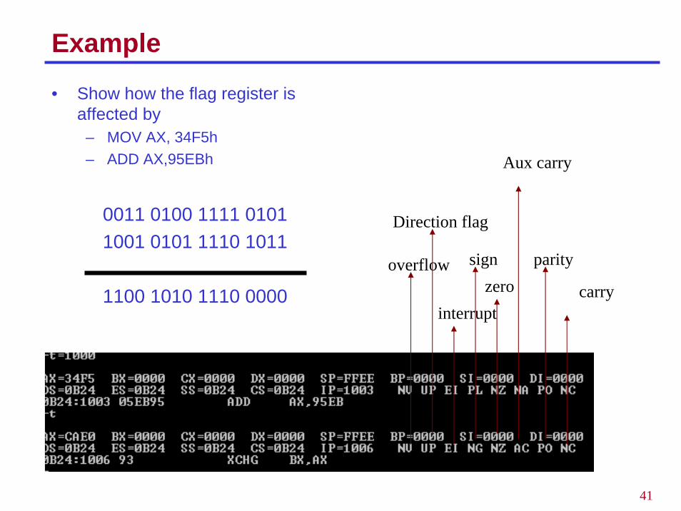
• Show how the flag register is affected by
– MOV AX, 34F5h– ADD AX,95EBh
0011 0100 1111 0101 1001 0101 1110 1011
1100 1010 1110 0000
overflow
Direction flag
interrupt
signzero
Aux carry
parity
carry
42
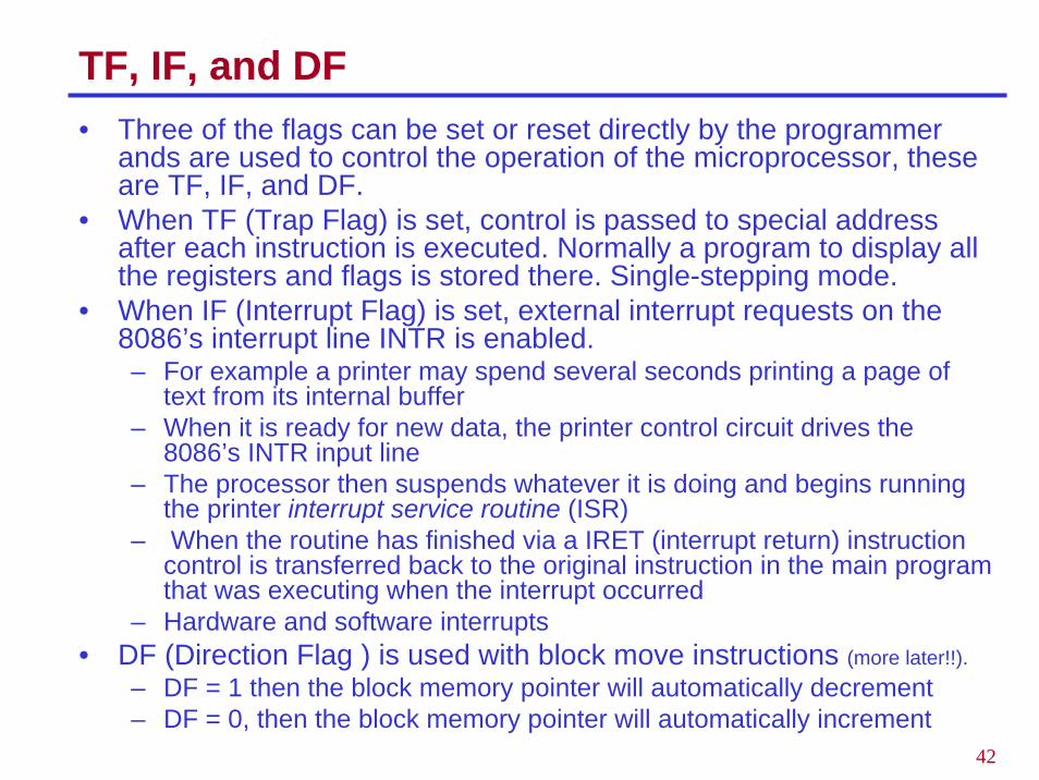
TF, IF, and DF• Three of the flags can be set or reset directly by the programmer
ands are used to control the operation of the microprocessor, these are TF, IF, and DF.
• When TF (Trap Flag) is set, control is passed to special addressafter each instruction is executed. Normally a program to display all the registers and flags is stored there. Single-stepping mode.
• When IF (Interrupt Flag) is set, external interrupt requests on the 8086’s interrupt line INTR is enabled. – For example a printer may spend several seconds printing a page of
text from its internal buffer– When it is ready for new data, the printer control circuit drives the
8086’s INTR input line– The processor then suspends whatever it is doing and begins running
the printer interrupt service routine (ISR)– When the routine has finished via a IRET (interrupt return) instruction
control is transferred back to the original instruction in the main program that was executing when the interrupt occurred
– Hardware and software interrupts• DF (Direction Flag ) is used with block move instructions (more later!!).
– DF = 1 then the block memory pointer will automatically decrement – DF = 0, then the block memory pointer will automatically increment
43
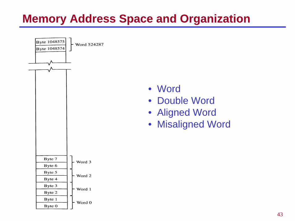
Memory Address Space and Organization
• Word • Double Word• Aligned Word• Misaligned Word
44
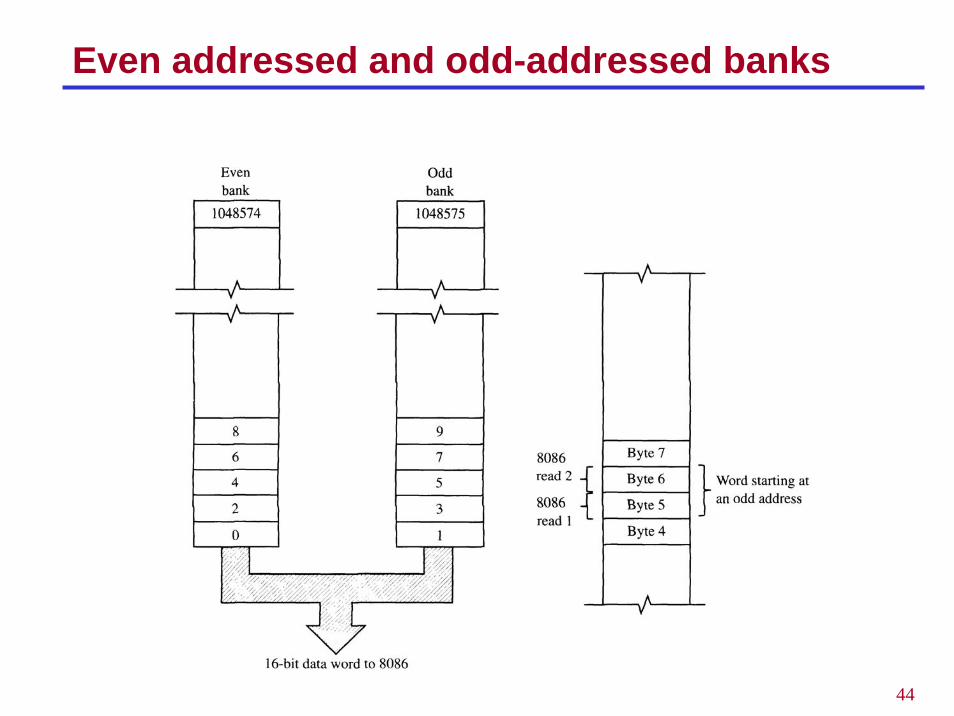
Even addressed and odd-addressed banks
45
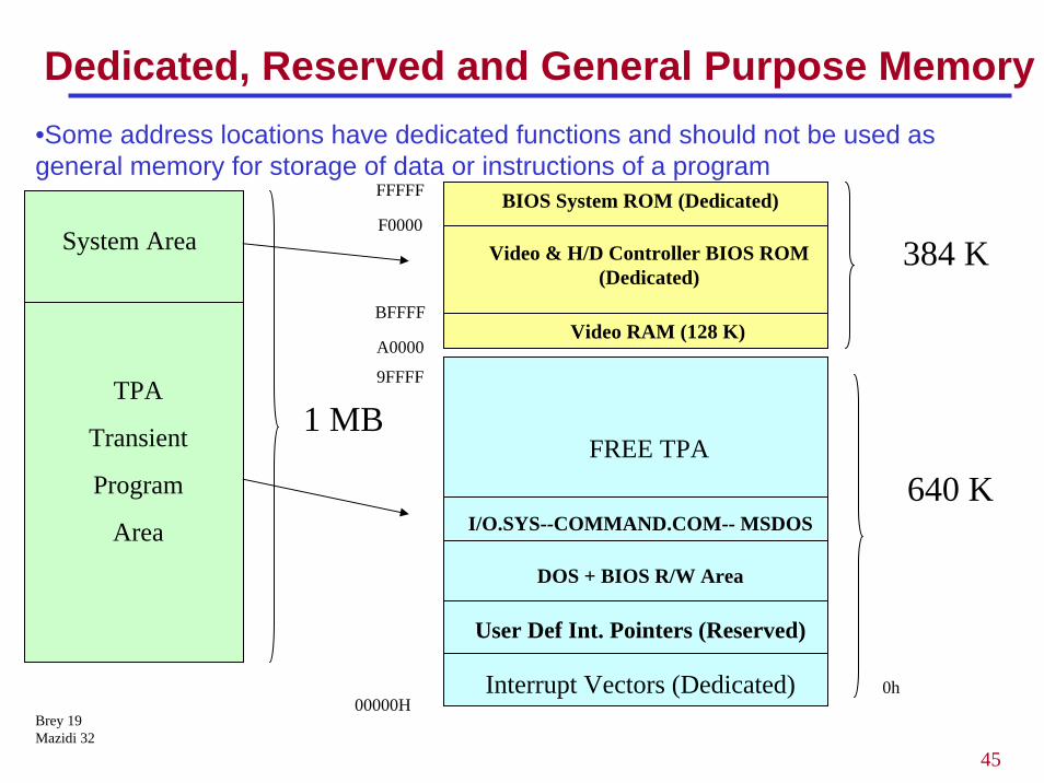
Dedicated, Reserved and General Purpose Memory
System Area
TPA
Transient
Program
Area
Interrupt Vectors (Dedicated)
User Def Int. Pointers (Reserved)
FREE TPA
DOS + BIOS R/W Area
640 K
1 MB
I/O.SYS--COMMAND.COM-- MSDOS
0h
•Some address locations have dedicated functions and should not be used as general memory for storage of data or instructions of a program
Brey 19Mazidi 32
384 K
BIOS System ROM (Dedicated)
Video RAM (128 K)
Video & H/D Controller BIOS ROM (Dedicated)
FFFFF
9FFFF
A0000
F0000
BFFFF
00000H
46
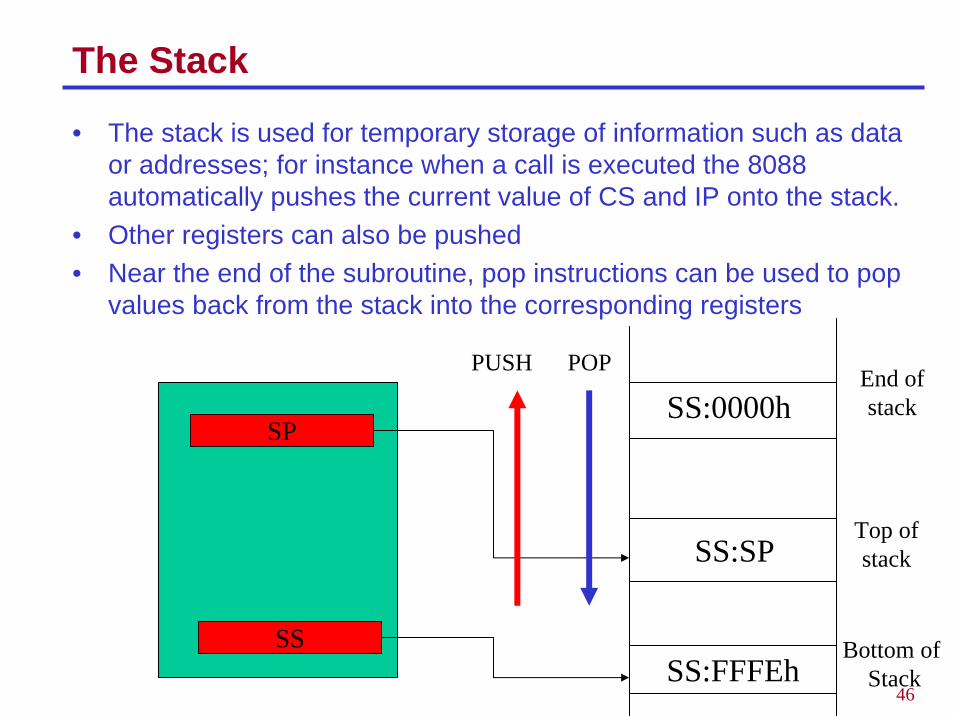
The Stack
• The stack is used for temporary storage of information such as data or addresses; for instance when a call is executed the 8088 automatically pushes the current value of CS and IP onto the stack.
• Other registers can also be pushed• Near the end of the subroutine, pop instructions can be used to pop
values back from the stack into the corresponding registers
SP
SS
SS:0000hEnd of stack
SS:SPTop ofstack
SS:FFFEhBottom of
Stack
PUSH POP
47
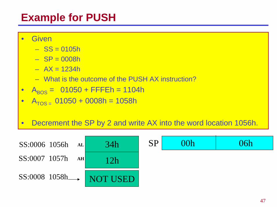
Example for PUSH
• Given– SS = 0105h– SP = 0008h– AX = 1234h– What is the outcome of the PUSH AX instruction?
• ABOS = 01050 + FFFEh = 1104h• ATOS = 01050 + 0008h = 1058h
• Decrement the SP by 2 and write AX into the word location 1056h.
34h
12h
SS:0006 1056h 00h 06hSP
NOT USED
AL
AHSS:0007 1057h
SS:0008 1058h
48
Example for POP
• What is the outcome of the followingPOP AXPOP BX
– if originally 1058h contained AABBh?
• Read into the specified register from the stack and increment the stack pointer for each POP operation
• At the first POP– AX = 1234h SP = 0008h
• At the second POP– BX = AABBh SP = 000Ah