Embed Size (px)
Citation preview
Products and solutions for gas distribution networks
CATALOGUEQUALIT Y IN PR ACTICE
2 0 1 6 / 2 0 1 7

QUALITY IN PRACTICE
CONTACT
WEBA is situated about 20 km from the city center of Poznan, and 300 km from Warsaw and Berlin.
Tel. +48 61 8158 601
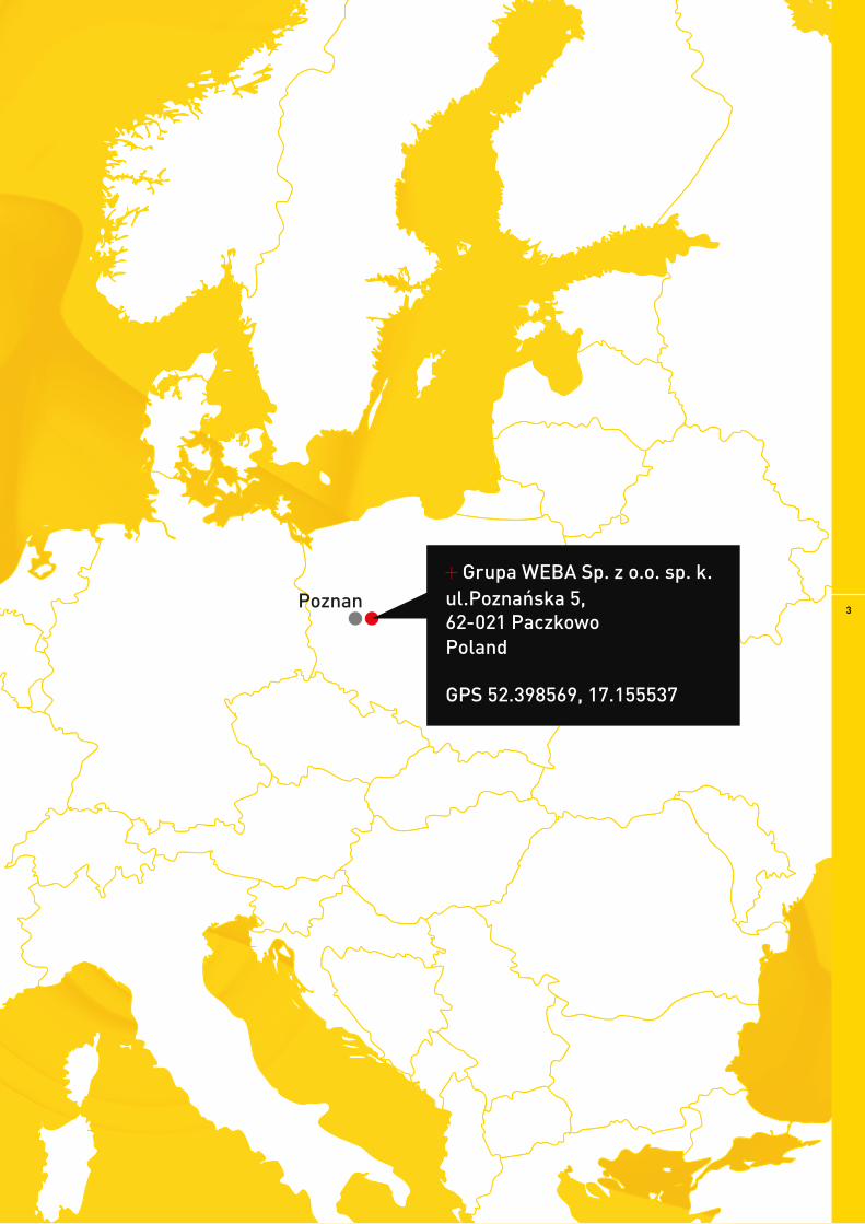
Grupa WEBA Sp. z o.o. sp. k.ul.Poznańska 5, 62-021 Paczkowo Poland
GPS 52.398569, 17.155537
Poznan 3
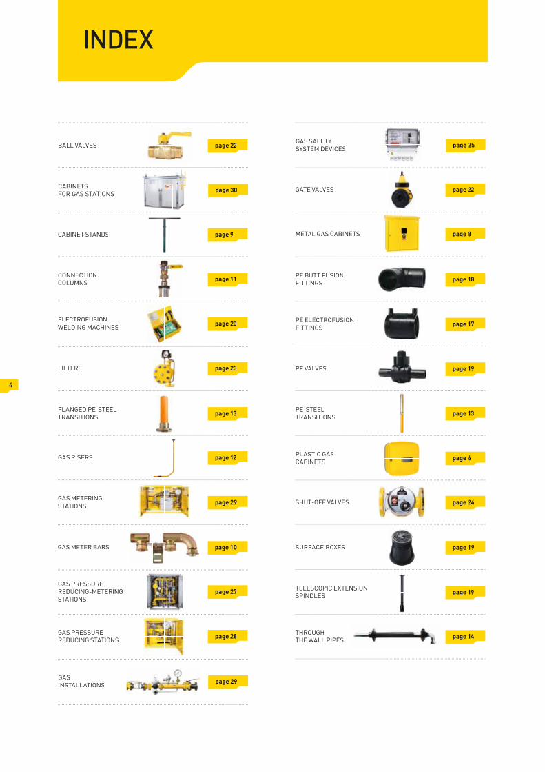
INDEX
BALL VALVES page 22
CONNECTIONCOLUMNS page 11
FILTERS page 23
FLANGED PE-STEELTRANSITIONS page 13
GAS RISERS page 12
GAS METERINGSTATIONS page 29
GAS PRESSUREREDUCING-METERINGSTATIONS
page 27
GAS PRESSUREREDUCING STATIONS page 28
GASINSTALLATIONS page 29
GAS SAFETYSYSTEM DEVICES page 25
GATE VALVES page 22
4
CABINET STANDS page 9
ELECTROFUSIONWELDING MACHINES page 20
METAL GAS CABINETS page 8
GAS METER BARS page 10
PE BUTT FUSIONFITTINGS page 18
PE ELECTROFUSIONFITTINGS page 17
PE VALVES page 19
PE-STEELTRANSITIONS page 13
PLASTIC GASCABINETS page 6
SHUT-OFF VALVES page 24
TELESCOPIC EXTENSIONSPINDLES page 19
SURFACE BOXES page 19
CABINETS FOR GAS STATIONS page 30
THROUGHTHE WALL PIPES page 14

A
Residential gas installation system
5A Plastic gas cabinetA
Gas meter barB
Gas meterC
Gas riserD
Stand for gas cabinetE
Surface boxF
G Telescopic extension spindle for PE valve
PE ball valveH
Connection columnI
Electrofusion fittingJ
Valve cabinetK
Through the wall pipeL
Gas pressure regulatorM
M
BC
D
E
F
G
D
I
L
K
JH
WEBA - one of the largest Polish companies manufacturing products for natural gas distribution networks and house connections. We specialise in providing comprehensive solutions for supplying natural gas and LPG for industrial and residential needs.
Our company provides all necessary equipment for gas connections in residential, public and industrial buildings.
We are also an authorised distributor of PE fittings and gas equipment of well-known European manufacturers.
You can configure with WEBA an optimal set up of brand and system-based solutions for building a complete gas installation. At the Client’s request, we will be happy to suggest the solutions to meet specific, national requirements and practices.

6
PLASTIC GAS CABINETS
index colour
06-30-0570-21 yellow
06-30-0570-22 brown
06-30-0570-23 light grey
GAS CABINETS
Plastic gas cabinets
Injection molded cabinets made from sturdy polypropylene
Self-extinguishing housing - safety
Convenient fi xing system for fi tters
Universal - fi ts all gas meters (G2,5/G4/G6) and regulators
Can be used with all elements of typical household gas connection available in the market
Cheap and simple stand solution for the gas cabinet
Dimensions: 574 mm (width) x 585 (height) x 245 (depth)
The body and the back wall are separate partsTime of installation shorter by about 30 minutes
Material: PP Warranty: 3 years
Technical parameters
CABINET IS ASSEMBLED ONCE THE INSTALLATION IS FINISHED
The gas meter bar can be moved 4 cm, in either direction, with the gas meter’s counter still visibleEasier installation of the cabinet
4 CM ADJUSTMENT RANGE
The solution designed to provide high reliability for cabinet's robustness
ADDITIONAL CONNECTION BETWEEN BODY AND THE BACK WALL OF THE CABINET
Overlapping of the door and the main body increasing the airtightness and watertightnessProtection of the cabinet against the weather conditions
CONTOURED CASING
DISMANTLING TO PIECES
No holes need to be drilled in cabinet for installation
Convenient and cheaper shipping thanks to dismantling to pieces
BUILT-IN SLOT FOR A GAS METER BAR
Features:

PLA
STIC
GA
S C
AB
INE
TS
PLASTIC GAS CABINETS
7
+ GAS PRESSURE REGULATOR FE 25
+ GAS METER G4
parameter option „A” option „B”
material polycarbonate with fiberglass
colour yellow, grey
flammability class V-0
glow wire flammability index IEC 60695-2-12
UV resistance UV stabilized
polypropylene
yellow, grey
V-2
IEC 60695-2-12
UV stabilized
PLASTIC VALVE CABINET 300 x 340 x 200 mm
MULTIPLE APPLICATIONS
Gas cabinet with pedestal - overall view
GAS CABINET 600 x 600 x 250 mmGAS CABINET 350 x 485 x 200 mm
Features:
UV resistant
Convenient installation on walls
Convenient mounting after completing the installation
Available in 3 colours: yellow, light grey, brown
Universal application
3-year warranty

02
WALL-MOUNTED GAS CABINETS RECESSED GAS CABINET
01
with fl at roof with slanted roof
8
STANDARD METAL GAS CABINETS
Sheet grade: DC01
Thickness: 0,8/1,0/1,5mm
Zinc coat thickness: 25 µm
Paint coat thickness: min. 60 µm
Colours: yellow RAL1018, brown RAL8017, light grey RAL7040other colours available on request
Technical parameters Unique features of our cabinets:
Anti-corrosion protection: double side zinc coated metal sheet -
various colours: yellow, brown, light grey - for standard boxes, black and antique copper for steel cabinets
At the Client’s request we can make cabinets in any colour.
FREE-STANDING GAS CABINETS
with slanted roof (for 2 horizontally mounted gas meters)
with slanted roof with slanted roof (for 2 vertically mounted gas meters)
01 02 03
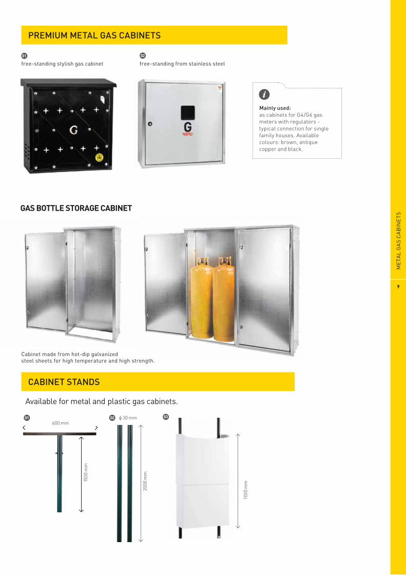
Mainly used:as cabinets for G4/G6 gas meters with regulators - typical connection for single family houses. Available colours: brown, antique copper and black.
PREMIUM METAL GAS CABINETS
01 02
free-standing stylish gas cabinet free-standing from stainless steel
2000
mm
02
CABINET STANDS
01
Available for metal and plastic gas cabinets.
03
1000
mm15
00 m
m
600 mm
GAS BOTTLE STORAGE CABINET
MET
AL G
AS
CA
BIN
ETS
9
Cabinet made from hot-dip galvanized steel sheets for high temperature and high strength.

Examples of Weba meter bars
Max.pressure: 10 bar
Working pressure: 2 kPa
Max. working temperature: 60 °C
Min. working temperature: -29 °C
Zinc coating: 8-12 µm
Conforming to: PN-EN ISO 3183:2015-5 ; PN-EN 10216-1:2014-2 ;PN-EN ISO 228-1:2005 ; PN-EN ISO 2081:2011 ;PN-EN 12732+A1:2014-09
Technicalparameters
At the Client’s request, we can make any meter bars to meet specifi c, national requirements and practices.
X Y
55 m
m
110mm
05 06
X Y
55 m
m
110mm
110mm
58 m
m
55mm
X Y
03
04
02
01
110mm95mm
Y
X
110mm 95mm
X
Y
110mm 95mm
X Y
110mm 80mm 90-160mm
53 m
m
110mm 95mm
Y
X
GAS METER BARS
10

photo index diameter PE
ending
05-30-0025-36 25 flange DN20
05-30-0032-03 32 thread 1”
05-30-0032-02 32 thread 5/4”
05-30-0032-17 32 ball valve DN15
05-30-0032-41 32 flange DN25
05-30-0040-03 *
*
*
* with PE casing
40 thread 1”
05-30-0040-04 40 thread 5/4”
05-30-0040-30 40 thread 1 1/2”
05-30-0050-07 50 thread 5/4”
05-30-0063-04 63 thread 1 1/2”
05-30-0063-28 63 thread 5/4”
05-30-0063-30 63 thread 2”
05-30-0063-32 63 flange DN50
05-30-0090-09 90 flange DN80
01 05-30-0025-33 25 ball valve DN15
02
03
1620
mm
500
mm
500
mm
1620
mm
1620
mm
WEBA columns advantages
sag efas eetnaraug ABEW yb snmuloc noitcennoC connections, e.g. to regulators in gas meterboxes.
,tinu noitisnart leets-EP a fo stsisnoc nmuloc noitcennoc A protected by an aluminum pipe and insulation foam. The conduit protects the PE pipe from high temperatures, UV radiation and mechanical damage.
noitallatsni ecuder yltnac fiingis snmuloc noitcennoc abeW time. Our solutions have been tested and proven in over 60 000 gas connections in Poland and abroad and this is why we cover them with 3 year warranty.
Max. pressure: 1 MPa
Working pressure: 0.5 MPa
Max. working temperature: 60 °C
Min. working temperature: -29 °C
Pipe steel: L360N
Conduit pipe: Aluminium
Flange steel: P245GH PE
PE100 PE-steel transition unit, approved by IGNiG no. AT/2014-03-11 ( ediition I/2014)
Conforming to: PN-EN 10208-1, PN-EN 10216-1, PN-EN 12329, PN-EN 1555-2
Technical parameters
01 02 03
The columns are available in sizes DN25 through DN90, with a choice of ends (fl anges, threads, taps,
CONNECTION COLUMNS
CO
NN
ECTI
ON
CO
LUM
NS
11
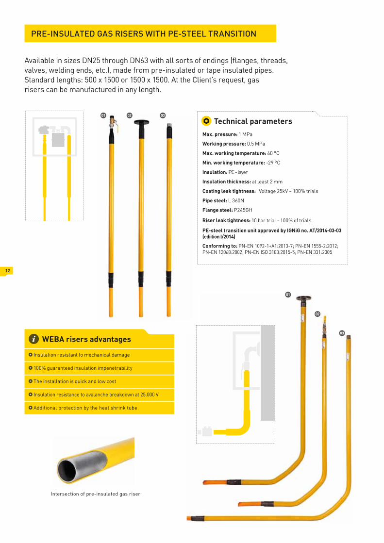
Available in sizes DN25 through DN63 with all sorts of endings (fl anges, threads, valves, welding ends, etc.), made from pre-insulated or tape insulated pipes. Standard lengths: 500 x 1500 or 1500 x 1500. At the Client’s request, gas risers can be manufactured in any length.
PRE-INSULATED GAS RISERS WITH PE-STEEL TRANSITION
01
02
03
Max. pressure: 1 MPa
Working pressure: 0.5 MPa
Max. working temperature: 60 °C
Min. working temperature: -29 °C
Insulation: PE - layer
Insulation thickness: at least 2 mm
Coating leak tightness: Voltage 25kV – 100% trials
Pipe steel: L 360N
Flange steel: P245GH
Riser leak tightness: 10 bar trial - 100% of trials
PE-steel transition unit approved by IGNiG no. AT/2014-03-03 (ediition I/2014)
Conforming to: PN-EN 1092-1+A1:2013-7; PN-EN 1555-2:2012; PN-EN 12068:2002; PN-EN ISO 3183:2015-5; PN-EN 331:2005
Technical parameters
WEBA risers advantages
Insulation resistant to mechanical damage
100% guaranteed insulation impenetrability
The installation is quick and low cost
Insulation resistance to avalanche breakdown at 25.000 V
Additional protection by the heat shrink tube
12
Intersection of pre-insulated gas riser
030201

PE-S
TEEL
TR
ANSI
TIO
NS
PE-STEEL TRANSITIONS
13
DN25-DN63: 300mmDN90-DN250: 400mm
DN25-DN63: 270mmDN90-DN250: 270mm
Working pressure: 0.5 MPa
Max. pressure: 1 MPa
Pipe steel: L360N
PE pipe: PE100 RC
PE-steel transition unit approved by IGNiG no. AT/2014-03-11 (ediitions I/2014)
Conforming to: PN-EN 1555-2:2012 ;PN-EN ISO 3183:2015-5
Technical parameters
FLANGED PE-STEEL TRANSITIONS
370mm
Working pressure: 0.5 MPa
Max. pressure: 1 MPa
Pipe steel: L360N
Flange steel: P245GH
PE pipe: PE100 RC
PE-steel transition unit, approved by IGNiG no. AT/2014-03-11 (ediitions I/2014)
Conforming to: PN-EN 1555-2:2012 ;PN-EN ISO 3183:2015-5 ; PN-EN 1092-1+A1:2013-07
Technical parameters
02 01
Pre-insulated PE-steel transition
PE-steel transition- galvanised
03
PE-steel transitionwith heat shrink tube
04
PE-steel transition made of carbon steel without zinc coating
14
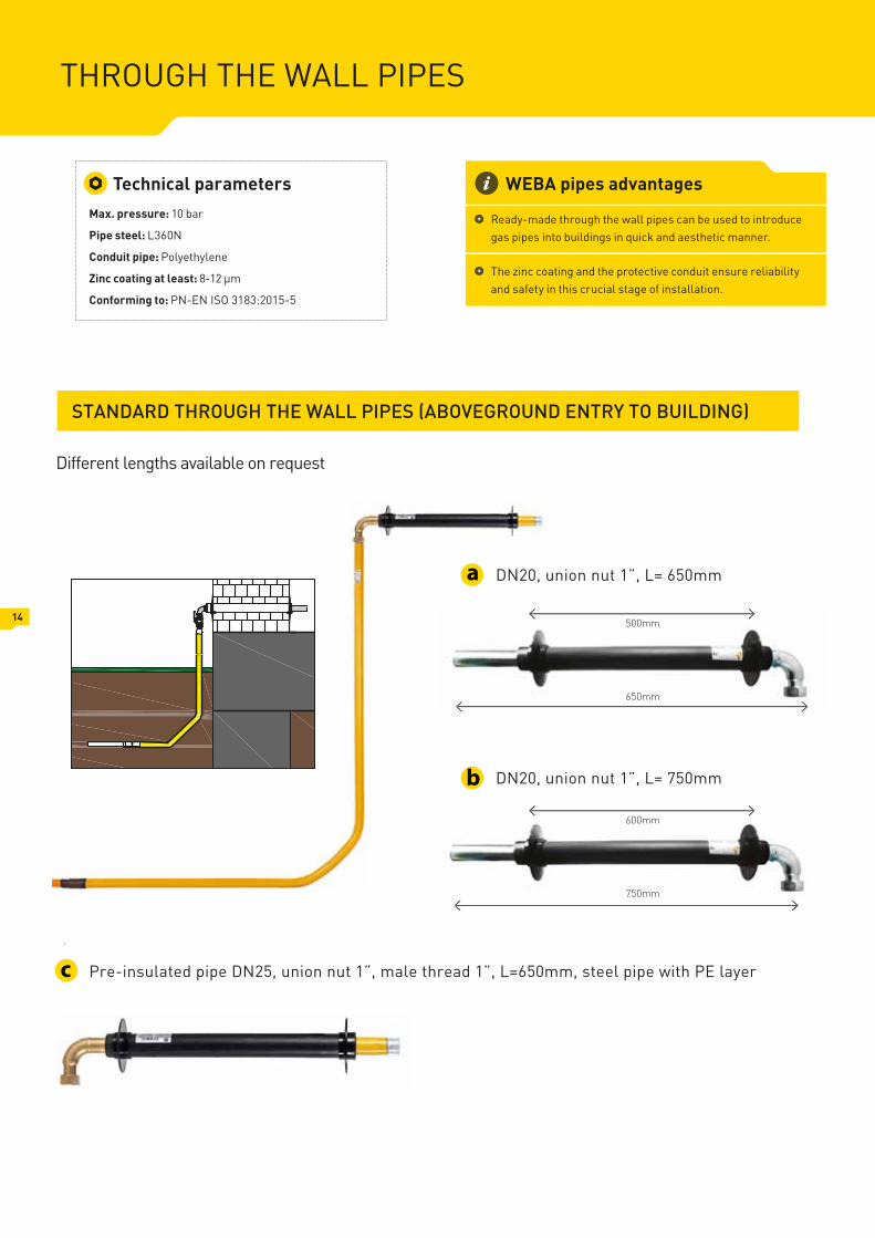
STANDARD THROUGH THE WALL PIPES (ABOVEGROUND ENTRY TO BUILDING)
Pre-insulated pipe DN25, union nut 1”, male thread 1”, L=650mm, steel pipe with PE layer
Max. pressure: 10 bar
Pipe steel: L360N
Conduit pipe: Polyethylene
Zinc coating at least: 8-12 µm
Conforming to: PN-EN ISO 3183:2015-5
Technical parameters WEBA pipes advantages
ecudortni ot desu eb nac sepip llaw eht hguorht edam-ydaeR gas pipes into buildings in quick and aesthetic manner.
ytilibailer erusne tiudnoc evitcetorp eht dna gnitaoc cniz ehT and safety in this crucial stage of installation.
650mm
500mm
DN20, union nut 1”, L= 650mma
750mm
600mm
DN20, union nut 1”, L= 750mmb
c
THROUGH THE WALL PIPES
Different lengths available on request

THROUGH THE FOUNDATION WALL PIPE (UNDERGROUND ENTRY TO BUILDING)
FLEXIBLE THROUGH THE FOUNDATION WALL PIPE (UNDERGROUND ENTRY TO BUILDING)
Pre-insulated pipe DN25 PE32 with elbow and ball valve 1” (female thread)
b
Pre-insulated pipe DN25 PE32 with angle ball valve 1” (female thread)
DN25 PE32, male thread 1”, stainless steel with PE coating, L=2100mm
c
Pre-insulated pipe DN32 PE40 with elbow and ball valve 1 1/4” (female thread)
a
Through the wall pipe with PE corrugated protection layerd
THR
OU
GH
TH
E W
ALL
PIP
ES
15

16
01
05
07
08
09
06
02 03
04
10
Electrofusion fi ttings are made from polyethylene (PE100) and serve to connect PE pipes used in gas and water installations. A resistance wire is incorporated in such fi ttings. Once connected to an electrofusion welding machine, current is passed through the wire which heats up the fi tting and the pipe to desired temperature, thus fusing both parts together.
Couplings
Equal tees
Saddles with T-Clamp Georg Fischer
Tapping tees Georg Fischer
Reducers
End caps
Valves for drilling under pressure
PE-Brass adaptors
Elbows
Tapping tees with clamp
PE ELECTROFUSION FITTINGS GAS / WATER

PE E
LEC
TRO
FUSI
ON
FIT
TIN
GS
GAS
/ W
ATER
17
01 02 03 03 04 05 06 07 08 09 10 10
90˚ 45˚ male thread female thread
20 25 x 20 25 63 25 25 40 x 25 63 x 63 63 x 25 63 x 32 25 x 3/4" 32 x 1"
25 32 x 20 32 75 32 32 50 x 25 75 x 63 63 x 32 63 x 63 32 x 1" 40 x 5/4"
32 32 x 25 40 90 40 40 63 x 25 90 x 63 63 x 40 32 x 5/4" 50 x 1 1/2"
40 40 x 25 50 110 50 50 90 x 25 110 x 63 63 x 63 32 x 1 1/2" 63 x 1"
50 40 x 32 63 125 63 63 110 x 25 125 x 63 40 x 1" 63 x 5/4"
63 50 x 32 75 160 75 75 40 x 32 160 x 63 40 x 5/4" 63 x 1 1/2"
75 50 x 40 90 180 90 90 50 x 32 180 x 63 40 x 1 1/2" 63 x 2"
90 63 x 32 110 200 110 110 63 x 32 200 x 63 50 x 1"
110 63 x 40 125 225 125 125 75 x 32 225 x 63 50 x 5/4"
125 63 x 50 160 250 160 140 90 x 32 250 x 63 50 x 1 1/2"
140 75 x 63 180 180 160 110 x 32 63 x 5/4"
160 90 x 63 200 200 180 125 x 32 63 x 1 1/2"
180 90 x 75 225 225 200 125 x 32 63 x 2"
200 110 x 63 250 250 225 160 x 32
225 110 x 90 250
250 125 x 63
280 125 x 90
315 125 x 110
355 160 x 110
400 180 x 125
450 200 x 160
500 225 x 160
250 x 160
250 x 180
250 x 200
Butt fusion fi ttings are made from polyethylene (PE100) and are used for building and repairing water and gas distribution networks. The butt welding of PE pipes and fi ttings consists in proper heating and plasticizing the ends of the elements to be connected by having them in contact with a heating plate; once the heating plate is removed, the ends are pushed together and the bond then naturally cools down.
PE BUTT FUSION FITTINGS GAS/WATER
01 02 03Elbows Reducers Flange adaptors

01 02 02 03 03 04 05 06 06
90 -̊SDR 17, 90 -̊SDR 11, 45 -̊SDR 17, 45 -̊SDR 11 SDR 17 SDR 11 SDR 17 SDR 11 SDR 17, SDR 11 SDR 17, SDR 11 SDR 17 SDR 11
90 90 x 63 90 x 63 90 25 90 90 90 x 63 110 x 90
110 110 x 63 110 x 63 110 32 110 110 110 x 90 125 x 90
125 110 x 90 110 x 90 125 40 125 125 125 x 90 125 x 110
140 125 x 63 125 x 63 140 63 140 140 125 x 110 140 x 90
160 125 x 90 125 x 90 160 90 160 160 140 x 90 140 x 110
180 125 x 110 125 x 110 180 110 180 180 140 x 110 160 x 90
200 140 x 90 140 x 90 200 125 200 200 160 x 90 160 x 110
225 140 x 110 140 x 110 225 140 225 225 160 x 110 180 x 90
250 140 x 125 140 x 125 250 160 250 250 180 x 90 180 x 110
280 160 x 90 160 x 90 280 180 280 280 180 x 110 180 x 125
315 160 x 110 160 x 110 315 200 315 315 180 x 125 180 x 140
160 x 125 160 x 125 225 180 x 140 180 x 160
160 x 140 160 x 140 250 180 x 160 225 x 110
180 x 90 180 x 90 280 225 x 110 225 x 125
180 x 110 180 x 110 315 225 x 125 225 x 160
180 x 125 180 x 125 225 x 160
180 x 140 180 x 140
180 x 160 180 x 160
200 x 125
200 x 140 200 x 140
200 x 160 200 x 160
200 x 180 200 x 180
225 x 110
225 x 140 225 x 140
225 x 160 225 x 160
225 x 180 225 x 180
225 x 200 225 x 200
250 x 160 250 x 160
250 x 180 250 x 180
250 x 200 250 x 200
250 x 225 250 x 225
280 x 180
280 x 200 280 x 200
280 x 225 280 x 225
280 x 250 280 x 250
315 x 225 315 x 225
315 x 250 315 x 250
315 x 280 315 x 280
04 05 06Tees End caps Reducing tees
18

GA
S VA
LVE
S
19
PE VALVES GAS / WATER
Alternative for cast iron valves. Polyethylene valves are lightweight and hence portable and easy to install. As they are made entirely from PE, there is no need for PE-cast iron connection. This solutions is incomparably more reliable and safer. PE valves have been tested and proven in thousands of installations.
TELESCOPIC EXTENSION SPINDLES FOR PE BALL VALVES
SURFACE BOXES
TELESCOPIC EXTENSION SPINDLES
For manual cutting off of gas flow through a valve. The columns’ height is adjustable, for example 80 cm to 120 cm, and they are lightweight and easy to install.
We produce telescopic extension spindles for PE valves and tapping saddles of other producers such as Georg Fischer, Frialen, Plasson, Polytec.
1800
- 29
00 m
m
Different lengths available on request
800
- 120
0 m
m
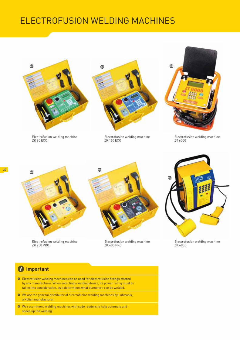
ELECTROFUSION WELDING MACHINES
Electrofusion welding machine ZK 90 ECO
Electrofusion welding machine ZK 250 PRO
Electrofusion welding machine ZK 160 ECO
Electrofusion welding machine ZT 6000
Electrofusion welding machine ZK 400 PRO
Electrofusion welding machine ZK 6000
Important
Electrofusion welding machines can be used for electrofusion fi ttings offered by any manufacturer. When selecting a welding device, its power rating must be taken into consideration, as it determines what diameters can be welded.
We are the general distributor of electrofusion welding machines by Labtronik, a Polish manufacturer.
We recommend welding machines with code readers to help automate and speed up the welding.
02 03
0405
06
01
20

*The specified scope of welded diameters is only for information purposes.Electrofusion fittings of the same diameter, but made by different manufacturers, may require higher or lower welding power.
NAME ZK 90 ECO ZK 160 ECO ZK 250 PRO ZK 400 PRO ZK 6000 ZT 6000
Approximate max. welding diameter* 90 160 250 400 630 630
Max. welding power [W] ~1200 ~1800 ~2200 ~3000 ~5000 ~5000
Supply voltage 230V (200V ÷ 250) AC - 50 Hz
Welding voltage 8 ÷ 42V (0.1V setting interval)
Welding time 1 ÷ 5000 s (1 s interval)
Cooling time 1 ÷ 99 min. (1 min. interval)
Backlit display LCD, 2 rows, each 16 characters LCD, 4 rows, each 20 characters
Keyboard numeric alphanumeric
Weld logger yes
No. of logged cycles 500 2048
Protocol of welds made yes
Manual entry of bar code yes
Manual setting yes
Repeating of last setting yes
Quick start of welding w/o using keyboard yes
Overhaul information yes
Automatic welding time compensation to ambient temp. yes
Welding process control yes
Viewing voltage, current and time remaining until the end of welding yes
Entering weld location, operator's name and construction site number no yes
Quick view of saved welds no yes yes no
Printing reports "in the field" on a thermal printer no yes yes no
Replaceable heating wire no yes
Automatic identification of fittings with built in resistor no yes
PC software yesyesyes
yesyes yesyes yesyesBar code reader
Working with USB pendrives option option option option yes yes
Cable length 3 m
Working temperature range 0 ÷ +40˚C
Storage temperature range - 20 ÷ +50˚C
Heating terminals 4,0 / 4,7 (included)
Dimensions 430 mm x 280 mm x 200 mm 300 x 220 x 300 mm
380 x 380 x 380 mm
Weight [kg] 19 22 22 27 21 29
Protection class IP 55 IP 65
Warranty (months) 24
Electrofusion welding machines - Technical data
ELEC
TRO
FUSI
ON
WEL
DIN
G M
AC
HIN
ES
21

BALL VALVES
01 02 03
01 02 03
DN 15, male thread 3/4" female thread 1/2" DN 32 PN16
DN 20, male thread 1" female thread 3/4" DN 40 PN16
female thread 1" DN 50 PN16
female thread 5/4" DN 65 PN16
female thread 1 1/2" DN 80 PN16
female thread 2" DN 100 PN16
DN 20 PN16 DN 125 PN16
DN 25 PN16 DN 150 PN16
GAS VALVES
spherical valve ball valve fl anged ball valve
Max. Pressure: 4MPa
Max. working temperature: 110°C
Min. working temperature: -30 °C
Conforming to technical approval: AT/98-05-0061
Technical parameters
GATE VALVES
Max. pressure: 16 bar
Leak tightness class: A
Max. working temperature: 60 °C
Min. working temperature: -20 °C
Nodular cast iron: EN-GJS-400-15
Seals: NITRILE RUBBER (NBR)
Conforming to technical approval AT/97-04-0047
Certifi cate UDT-CERT CSJ/122/2010
Conforming to: PN-EN 1563 PN-EN 1629 PN-EN 1982
Technical parameters (JAFAR)
Gate valves by HAWLE and JAFAR – fl anged gate valves available in sizes DN 40 through DN 300, gate valves with PE ends available in sizes: PE 32 DN 25, PE40 DN 32, PE 63 DN 50.
We select optimal valve columns during the execution of the project.
22
GA
S FI
LTER
S
23
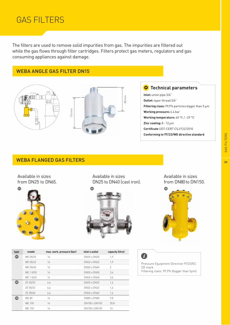
WEBA ANGLE GAS FILTER DN15
WEBA FLANGED GAS FILTERS
GAS FILTERS
80 m
m
116
mm
Inlet: union pipe 3/4”
Outlet: taper thread 3/4”
Filtering class: 99,9% particles bigger than 5 µm
Working pressure: 6.4 bar
Working temperature: 60 °C / -29 °C
Zinc coating: 8 - 12 µm
Certifi cate UDT-CERT CSJ/122/2010
Conforming to 97/23/WE directive standard
Technical parameters
The fi lters are used to remove solid impurities from gas. The impurities are fi ltered out while the gas fl ows through fi lter cartridges. Filters protect gas meters, regulators and gas consuming appliances against damage.
Available in sizes from DN25 to DN65.
Available in sizes DN25 to DN40 (cast iron).
Available in sizes from DN80 to DN150.
model max. work. pressure (bar) inlet x outlet capacity (litre)
16
16
16
16
WE 05/25
WE 05/32
WE 05/40
16
16
16
WE 80
WE 100
WE 150
WE 1.0/50
Pressure Equipment Directive 97/23/ECCE markFiltering class: 99,9% (bigger than 5µm)
16
6,4
6,4
6,4
1,9
1,9
2
3,6
9,8
20,8
16
3,6
1,6
1,6
1,6
WE 1.0/65
ZE 05/25
ZE 05/32
ZE 05/40
DN25 x DN25
DN32 x DN32
DN40 x DN40
DN80 x DN80
DN100 x DN100
DN150 x DN150
DN50 x DN50
DN65 x DN65
DN25 x DN25
DN32 x DN32
DN40 x DN40
type
01 02 03
01
02
03

SHUT OFF SOLENOID VALVES- MAG 3 FLAP VALVE
SHUT OFF SOLENOID VALVES MADAS
SHUT OFF VALVES- ZB STOP VALVE
SAFETY SYSTEMS
For use outside buildings, in medium pressure installations, up to 5 bar. Once detectors sense the presence of gas in a room, the supply of gas to the installation is shut off. Opened only manually.
The closing is automatic when, for accidental causes, the value of the regulation pressure goes up the set pressure.The valve reset is only manual and can be done only after verifying the causes and solving the problem that provoked the closing.
Valves adapted for operation with gas detectors. Opened manually, closed with electric impulse (or manually) from, e.g. a gas detection system. No power is required. The valves can be used in low pressure installations in public utility buildings, apartment blocks and single family house, etc.
Active gas installation safety systems are intended for automatic shut-off of infl ow of gas into the system where a leak has occurred. The shut-off is effected by the following devices working in cooperation: gas sensor, alarm module, solenoid valve and acoustic-optical signaling device. When the sensor detects gas, it sends a signal to the alarm module which in turn sends a signal to the solenoid valve and closes the valve and to the acoustic-optical signalling device.
24

SAFE
TY S
YSTE
MS
25
GAS THERMAL PROTECTIVE DEVICES
GAS DETECTORS
In case of fi re, valves prevent gas leakage from installations damaged by the fi re, especially from gas consuming appliances (boilers, cookers). The valves are triggered by temperature. Once a temperature of 90’C is reached, the fl ow of gas is automatically shut off. The valves remain leak tight up to 900’C.
We offer methane, propane, butane and carbon monoxide detectors. They are designed to detect and indicate dangerous concentration of gases.
Alarm modules are designed to control and power supply for gas detectors. They control external devices like solenoid valves and alerting devices.
L2
L1

26
GAS STATIONS ARE MANUFACTURED SERIALLY AND HAVE MODULAR DESIGN.
High quality thanks to serially manufactured modules
Perfected technology
Predictable cabinet size
Optional extension and installation of extra equipment without having to replace the cabinet
MODULAR DESIGN ENSURES:
WEBA provides a comprehensiverange of R&M stations which are designed, engineered and tested to comply with client specification as well as International standards
GAS PRESSURE REDUCING AND METERING STATIONS (R&M STATIONS)
GA
S P
RES
SUR
E R
EDU
CIN
G A
ND
MET
ERIN
G S
TATI
ON
S (R
&M
STA
TIO
NS)
27
400 mm
700
mm
1000 mm
01 03
0405
06
07
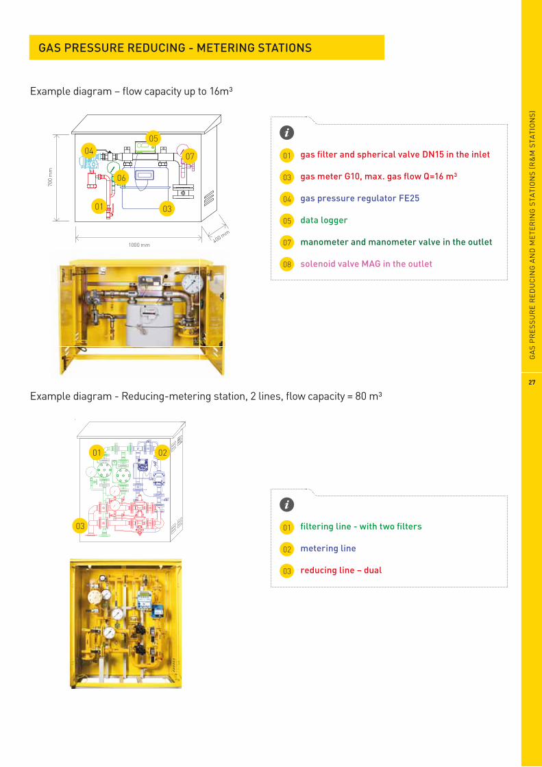
Example diagram – flow capacity up to 16m³
Example diagram - Reducing-metering station, 2 lines, flow capacity = 80 m³
gas fi lter and spherical valve DN15 in the inlet
gas meter G10, max. gas fl ow Q=16 m³
gas pressure regulator FE25
data logger
manometer and manometer valve in the outlet
solenoid valve MAG in the outlet
01
03
04
05
07
08
fi ltering line - with two fi lters
metering line
reducing line – dual
01
02
03
01 02
03
GAS PRESSURE REDUCING - METERING STATIONS
28
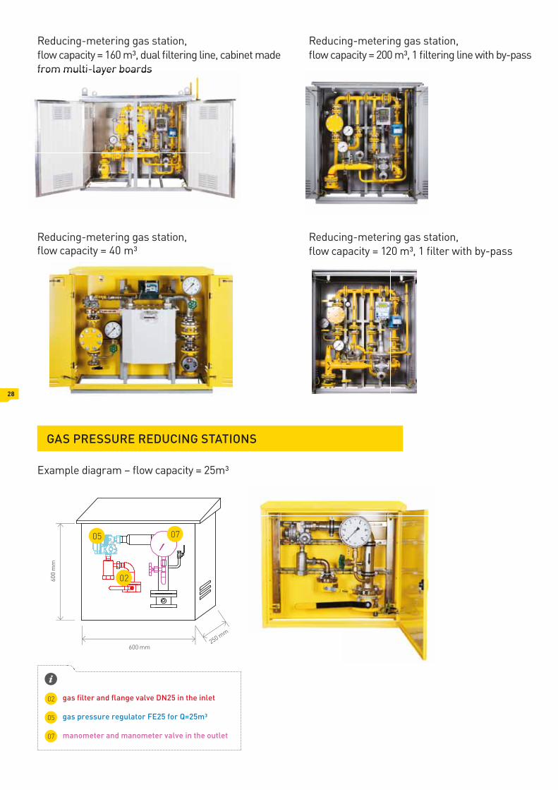
Reducing-metering gas station, flow capacity = 160 m³, dual filtering line, cabinet made from multi-layer boards
Example diagram – flow capacity = 25m³
Reducing-metering gas station, flow capacity = 200 m³, 1 filtering line with by-pass
Reducing-metering gas station, Reducing-metering gas station, flow capacity = 40 m³ flow capacity = 120 m³, 1 fi lter with by-pass
gas fi lter and fl ange valve DN25 in the inlet
gas pressure regulator FE25 for Q=25m³
manometer and manometer valve in the outlet
02
05
07
GAS PRESSURE REDUCING STATIONS
05 07
02
250 mm
600
mm
600 mm
29
GAS METERING STATIONS
GAS INSTALLATIONS
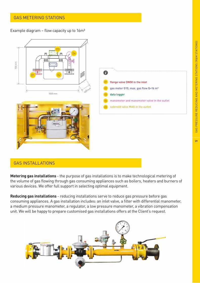
Example diagram – flow capacity up to 16m³
01 02
0304
400 mm
700
mm
1000 mm
01
02
03
04
05
flange valve DN50 in the inlet
gas meter G10, max. gas fl ow Q=16 m³
data logger
manometer and manometer valve in the outlet
solenoid valve MAG in the outlet
Metering gas installations - the purpose of gas installations is to make technological metering of the volume of gas fl owing through gas consuming appliances such as boilers, heaters and burners of various devices. We offer full support in selecting optimal equipment.
Reducing gas installations - reducing installations serve to reduce gas pressure before gas consuming appliances. A gas installation includes: an inlet valve, a fi lter with differential manometer, a medium pressure manometer, a regulator, a low pressure manometer, a vibration compensation unit. We will be happy to prepare customised gas installations offers at the Client’s request.
GA
S P
RES
SUR
E R
EDU
CIN
G A
ND
MET
ERIN
G S
TATI
ON
S (R
&M
STA
TIO
NS)

CABINETS FOR GAS STATIONS
CABINETS MADE FROM ALUMINIUM SANDWICH PANELS
CABINET MADE FROM MULTI-LAYER BOARD
CABINETS MADE FROM SHEETS OF STEEL OR ALUMINIUM
steel or aluminium sheet
steel or aluminium sheet
rigid polyurethane foam
30
GAS POINTS AND STATIONS
Quality in Practice

Grupa WEBA Sp. z o.o. sp. k. ul. Poznańska 5, 62-021 Paczkowo, Poland VAT No.: PL 7772619447 Reg. No. (KRS): 00000 70152 www.WEBA.com.pl
e-mail: [email protected] Tel. +48 61 8 158 628 / +48 61 8 158 640 Fax +48 61 8158 601


![15. Tehnologije Weba i aplikacijski poslužitelj [865,88 KiB]](https://img.dokumen.tips/doc/110x75/5890537d1a28abbc288c432b/15-tehnologije-weba-i-aplikacijski-posluzitelj-86588-kib.jpg)
