Embed Size (px)
Citation preview
RAJASTHAN INSTITUTE OF ENGG & TECHNOLOGY, JAIPURDEPARTMENT OF MECHANICAL ENGINEERING
B.TECH. II YEAR IV SEM(BRANCH: MECHANICAL ENGINEERING)
II MID TERM EXAM APRIL 2018SUBJECT: - IC ENGINE
SET-AMax. Time: 2 Hrs. Max. Marks: 20Note: - Attempt all questions.
Each question carries equal marks
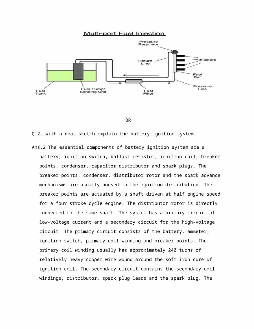
Q.1. Explain the principle of carburetion. With a suitable sketch explain the starting circuit of a solex
carburetor.
Ans.1 The carburetor works on Bernoulli's principle: the faster air moves, the lower its static pressure, and the
higher its dynamic pressure. The throttle (accelerator) linkage does not directly control the flow of liquid fuel.
Instead, it actuates carburetor mechanisms which meter the flow of air being pushed into the engine. The speed
of this flow, and therefore its pressure, determines the amount of fuel drawn into the airstream.
Both air and gasoline are drawn through the carburetor and into the engine cylinders by the suction
created by the downward movement of the piston. This suction is due to an increase in the volume of the
cylinder and consequent decrease in the gas pressure in this chamber. It is the difference between the
atmosphere and cylinder that causes the air to flow into the chamber. In the carburettor, air passing into
the combustion chamber picks up fuel discharged from a tube. This tube has a fine orifice called
carburettor jet which is exposed to the air path. The rate at which fuel is discharged into the air depends
on the pressure difference and pressure head between the float chamber and the throat of the venture and
on the area of the outlet of the tube. In order that the fuel drawn from the nozzle may be thoroughly
atomized, the suction effect must be strong and the nozzle outlet comparatively small. In order to produce
a strong suction, the pipe in the carburetor carrying air to the engine is made to have a restriction. At this
restriction called throat due to increase in velocity of flow, a suction effect is created. The restriction is
made in the form of a venturi to minimize throttling losses. The end of the fuel jet is located at the
venturi or throat of the carburetor. The geometry of venturi tube is has a narrower path at the centre so
that the flow area through which the air must pass considerably reduced. As the same amount of air must
pass through every point in the tube, its velocity will be greatest at the narrowest point smaller the area,
the greater will be the velocity of the air, and thereby suction is proportionately increased.
As mentioned earlier, the opening of the fuel discharge jet is located where the suction is maximum
normally, this is just below narrowest section of the venturi tube. The spray of gasoline from the nozzle
and the air entering through the venturi tube are mixed together in this region and a combustible mixture
is formed which passes through intake manifold into the cylinders. Most of the fuel gets atomized
simultaneously a small part will be vaporized Increased air velocity a throat of the venturi helps the rate
of evaporation of fuel. The difficulty of obtaining a mixture of sufficiently high fuel vapour-air ratio for
starting of the engine and for uniform fuel-air ratio in different (in case of multicylinder engine) cannot be
fully met by the in velocity alone at the venturi throat.
Solex Carburetor Starting Circuit
The throttle valve remains in closed position during starting. The petrol is supplied to the starter petrol jet
through the first passage from the float chamber. And the air through the starter air jet for starting
operation. Starting Valve which has different sizes hole is made from a flat disc. The position of various
holes can be adjusted in front of starter petrol jet by starter lever. Then air is mixed coming from starter
air jet. This air-fuel mixture passes through another hole of starter valve, in a passage of the carburetor,
below the throttle valve. The suction stroke of the engine sucks this mixture into the cylinder. This
mixture is rich enough to start the engine. After the engine starts and speed increases, a weak mixture is
required. Hence a small hole of the starter valve is brought in front of the starter petrol jet by means of
starter lever. Thereby reducing the quantity of petrol, this weakens the air-fuel mixture. Similarly, next
smaller hole of the starter valve is brought in front of starter petrol jet till the engine attains its normal
speed. Then after the starter valve is closed by bringing the starter lever to its off position.

OR
Q.1. What are the main functions of an injection pump? What are the functional requirements of an
injection system?
Ans.1 Fuel pump pumps gasoline from the vehicle’s fuel tank to the engine and also distribute fuel under
low pressure to the carburetor or to the fuel injection system under higher pressure. Carburetor
engines utilize low pressure pumps, which are located outside of the fuel tank. Fuel-injected engines
typically utilize electric fuel pumps mounted in the fuel tank.
It has four major functions:
The major job of injection pumps is to feeds the fuel. It compresses the fuel to high pressure
where cam lifts the plunger and then sent it to the injector.
It adjusts the fuel quantity. If the quantity of fuel which is injected is changed with engine speed
and its timing remains the same, the outcome and the fuel dissipation will change. As the output
of the engine is in proportion with injected fuel quantity, this is adjusted with the accelerator.
Another important function is to adjust the injection timing. It manages the timing from the point
where fuel is injected, ignited and combusted when maximum combustion pressure is reached.
Lastly, it atomizes the fuel in order to improve the ignition which results in complete combustion.
Functional objectives for fuel injection systems vary but all of them share the central task of
supplying fuel to the combustion process. There are several competing objectives such as:
Power output, fuel emission, emissions performance, reliability, smooth operation, initial cost,
maintenance cost.
Requirements of fuel injection system are:
i) Accurate metering of the fuel injected per cycle: The quantity of the fuel metered should vary to met
changing speed and load requirements of the engine
ii) Timing the injection of the fuel correctly in the cycle: to obtain maximum power ensuring fuel
economy and clean burning.
iii) Proper control of rate of injection: The desired heat - release pattern is achieved during combustion.

iv) Proper atomization of fuel into very fine droplets.
v) Proper spray pattern to ensure rapid mixing of fuel and air.
vi) Uniform distribution of fuel droplets throughout the combustion chamber.
vii) To supply equal quantities of metered fuel to all cylinders case of multi cylinder engines
viii) No lag during beginning and end of injection i.e., to eliminate dribbling of fuel droplets into the
cylinder.
Q.2. With a neat sketch explain the functions of MPFI system.
Ans.2 M.P.F.I. means Multi Point Fuel Injection system. In this system each cylinder has number of
injectors to supply/spray fuel in the cylinders as compared to one injector located centrally to
supply/spray fuel in case of single point injection system. Multiport fuel injection injects fuel into
the intake ports just upstream of each cylinder's intake valve. In this system each cylinder has
number of injectors to supply or spray fuel in the cylinders intake manifold space. MPFI system
injects fuel into individual cylinders, based on commands from the ‘on board engine management
system computer’ – popularly known as the Engine Control Unit/ECU. These techniques result not
only in better ‘power balance’ amongst the cylinders but also in higher output from each one of
them, along with faster throttle response. The power is produced in a petrol engine is by burning the
fuel. In petrol engine, the petrol is ignited. At first, the petrol is allowed to mix with air. It is then
ignited in a cylinder called as the combustion chamber. This combustion of the petrol produces a
sufficient energy to run the engine. The Carburetor is being used in the earlier days before the
invention of MPFI engine. It is the duty of the carburetor to mix the fuel and air in a fixed air-fuel
ratio. The fuel thus mixed in the carburetor is then given to the combustion chamber where this
mixture gets ignited. The power thus obtained from the ignition of gas is used to drive the engine.
The main disadvantage of the Carburetor is that the mixing of fuel and air is not in the proper ratio
which leads to the wastage of fuel and the pollution is high. Since the emission rate is high in
carburetor engine, the MPFI engine is being introduced.
ECM (Engine Control Module) and its function
The function of ECM is to receive signal from various sensors, manipulate the signals and send control
signals to the actuators. Sensors; Sensing different parameters (Temperature, Pressure, Engine Speed etc.)

of the engine and send signal to ECM. Actuators; Receives control signal from ECM and does function
accordingly (ISCA, PCSV, Injectors, Power Transistor etc.)
Case I: If ECM fails to send control signal to all actuators then the engine won't get started.
Case II: If ECM fails to service from all sensors then also the engine won't get started.
OR
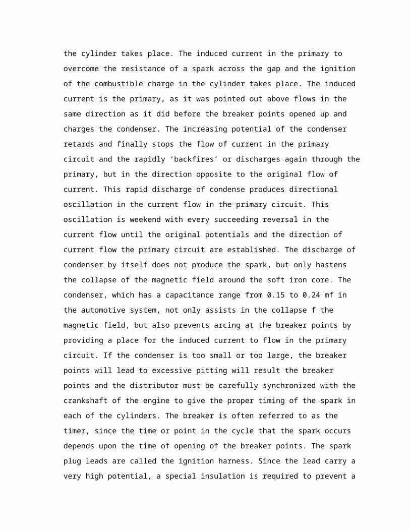
Q.2. With a neat sketch explain the battery ignition system.
Ans.2 The essential components of battery ignition system are a battery, ignition switch, ballast resistor,
ignition coil, breaker points, condenser, capacitor distributor and spark plugs. The breaker points,
condenser, distributor rotor and the spark advance mechanisms are usually housed in the ignition
distribution. The breaker points are actuated by a shaft driven at half engine speed for a four stroke
cycle engine. The distributor rotor is directly connected to the same shaft. The system has a primary
circuit of low-voltage current and a secondary circuit for the high-voltage circuit. The primary circuit
consists of the battery, ammeter, ignition switch, primary coil winding and breaker points. The
primary coil winding usually has approximately 240 turns of relatively heavy copper wire wound
around the soft iron core of ignition coil. The secondary circuit contains the secondary coil windings,
distributor, spark plug leads and the spark plug. The secondary windings consists of about 21000
turns of small, well insulate copper wire.
Schematic diagram of Battery Ignition System
When the ignition switch and the breaker points are closed a low-voltage current flows from the
battery through the primary circuit and builts up a magnetic field around the soft iron core of the
ignition coil. When the breaker points are opened by the action of the cam on the distributor shaft,
the primary circuit is broken and the magnetic field begins to collapse, an induced current from the
collapsing magnetic field flows in the same direction in the primary circuit as the battery current and
charges the condenser which acts as a reservoir for the flowing current due to a rapidly collapsing
magnetic field, high voltage is induced in the primary (it might be as high as 250 volts) and even
higher in the secondary (10,000 to 20,000 volts). The high voltage in the secondary passes through
the distributor rotor to one of the spark plug leads and into the spark plug. As soon as sufficient
voltage is built up in the secondary to overcome the resistance of a spark plug, the spark arcs across
the gap and the ignition of the combustible charge in the cylinder takes place. The induced current in
the primary to overcome the resistance of a spark across the gap and the ignition of the combustible
charge in the cylinder takes place. The induced current is the primary, as it was pointed out above
flows in the same direction as it did before the breaker points opened up and charges the condenser.
The increasing potential of the condenser retards and finally stops the flow of current in the primary
circuit and the rapidly ‘backfires’ or discharges again through the primary, but in the direction
opposite to the original flow of current. This rapid discharge of condense produces directional
oscillation in the current flow in the primary circuit. This oscillation is weekend with every
succeeding reversal in the current flow until the original potentials and the direction of current flow
the primary circuit are established. The discharge of condenser by itself does not produce the spark,
but only hastens the collapse of the magnetic field around the soft iron core. The condenser, which
has a capacitance range from 0.15 to 0.24 mf in the automotive system, not only assists in the
collapse f the magnetic field, but also prevents arcing at the breaker points by providing a place for
the induced current to flow in the primary circuit. If the condenser is too small or too large, the
breaker points will lead to excessive pitting will result the breaker points and the distributor must be
carefully synchronized with the crankshaft of the engine to give the proper timing of the spark in
each of the cylinders. The breaker is often referred to as the timer, since the time or point in the cycle
that the spark occurs depends upon the time of opening of the breaker points. The spark plug leads
are called the ignition harness. Since the lead carry a very high potential, a special insulation is
required to prevent a short circuit. Even with the special insulation, these leads are subjected to
breakdowns which result in high-tension short circuits and to leakage that lower the voltage
available at the work plug. Also, the leads should be shielded to aid in the prevention of radio
interference.
Q.3.What are the various components to be lubricated in an engine and explain how it is accomplished?
Ans.3 The objective of applying lubrication to engine parts are:
1. To reduce the frictional forces between the parts having a relative motion by minimizing the force
of friction and ensures the smooth running of the engine.
2. To reduce the wear and tear of moving parts.
3. To cool the surfaces by carrying away the heat generated due to friction.
4. To seal a space adjoining the surfaces such as piston rings and cylinder linear.
5. To absorb the shocks between bearings and other parts and consequently, reduce noise.
6. To act as a cleaning agent and removing dirt, grit and any deposits that might be present between
the moving parts of an automobile.
7. To help the piston rings to seal the gases inside the piston cylinder.
Parts of Engine Requires Lubrication:The main parts of the engine which need lubrication are:
1. Main crankshaft bearings.
2. Big end bearings or crank pin.
3. Gudgeon in bearings.
4. Piston rings and cylindrical walls.
5. Timing gears.
6. Camshaft and camshaft bearings.
7. Valve mechanism
8. Valve guide, valve tappets, rocker arms.
9. Governor and
10. Water pump bearing.
In order to ensure adequate supplies of oil to the engine parts, a reservoir of oil is provided by the sump
which is the lower part of the lubrication system and in automobile engines the sump is the oil pan. From
the reservoir, oil is distributed throughout the engine either by the splash system or the full pressure
system. In case of two-stroke engines, the crankcase cannot be used as an oil reservoir. The lubrication, in
this case, is provided by mixing a small proportion of oil with petrol. In the splash system the oil is
maintained in little troughs. There are dippers at the ends of the connecting rods to splash the oil on the
various parts like cylinder walls, camshafts, gudgeon pins etc. as they travel through the oil troughs
towards the bottom of the stroke of the piston. The oil is supplied to the main bearings under pressure due
to an oil pump through drilled passages, in the crankcase, called galleries. The oil pump also replenishes
the troughs. The system is now practically obsolete. The oil is fed to the crankshaft main journal bearings
and in some cases to the camshaft bearings through various branch cross-drillings in the crankcase. A few
heavy commercial engines use a separate pipe located underneath the main-bearing caps and by pedestal
brackets. Drillings in these brackets connect the gallery-pipe oil to the main bearings. By diagonal
drillings in the crankshaft continuous oil is fed to the big-end bearings from the oil grooves around the
main-bearings liners. These drillings pass from the main-bearing journal to the big-end crankpins through
the crankshaft web.
OR
Q.3. What are the advantages and limitations of an air cooling system?
Ans.3 In an air-cooling system, the outer surface of the cylinder and cylindrical head in reciprocating
engine is cooled by air flowing over them. To increase the heat transfer rate from the surface, the
metallic fins are cast on the cylinder and cylinder head. These fins increase the heat transfer area and
thereby heat transfer rate. Air cooling system is a very simple, reliable and maintenance-free cooling
system, with no operating cost. It is very suitable for small engines of automobiles.

Applications of Air-cooling System:
1. Air-cooling system is used in small engines, i.e., motor cycles, scooters, mopeds, airplanes and
combat tanks, where speed of the vehicle gives a good velocity to the air to cool the engine.
2. It is also used in small stationary engines used for agriculture and industries.
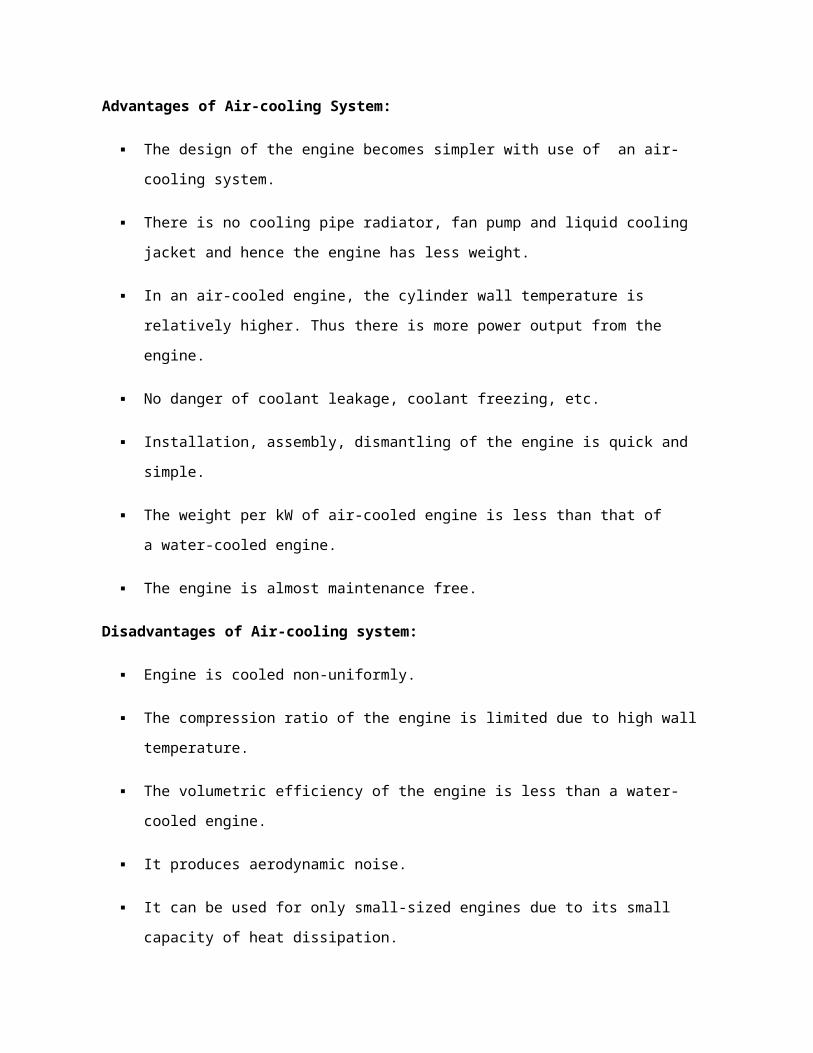
Advantages of Air-cooling System:
The design of the engine becomes simpler with use of an air-cooling system.
There is no cooling pipe radiator, fan pump and liquid cooling jacket and hence the engine has
less weight.
In an air-cooled engine, the cylinder wall temperature is relatively higher. Thus there is more
power output from the engine.
No danger of coolant leakage, coolant freezing, etc.
Installation, assembly, dismantling of the engine is quick and simple.
The weight per kW of air-cooled engine is less than that of a water-cooled engine.
The engine is almost maintenance free.
Disadvantages of Air-cooling system:
Engine is cooled non-uniformly.
The compression ratio of the engine is limited due to high wall temperature.
The volumetric efficiency of the engine is less than a water-cooled engine.
It produces aerodynamic noise.
It can be used for only small-sized engines due to its small capacity of heat dissipation.
Q.4. Mention the effect of supercharging on engine performance. Explain with a graph the three possible
theoretical scavenging processes.
Ans.4 The power output of an engine depends upon the amount of air indicated per unit time, the degree
of utilization of the air and the thermal efficiency of the engine. The amount of air inducted per unit
time can be increased by increasing the engine speed or by increasing the density of air at intake.
The increasing the engine speed calls for rigid and robust engine as the inertia loads increase. The
engine friction and bearing loads also increase and the volumetric efficiency decreases when the
speed is increased. The method of increasing the inlet air density, called supercharging, is usually
employed to increase the power output of the engine. This is done by supplying air at a pressure
higher than the pressure at which the engine naturally aspirates air from the atmosphere by using a
pressure boosting device called a supercharger. The power output can also be increased by
increasing the thermal efficiency of the engine, say, by increasing the compression ratio. However,
this increases the maximum cylinder pressure. The rate of increase of maximum cylinder pressure is
less than rate of increase of break mean effective pressure in case of supercharged engine.
EFFECT OF SUPERCHARGING ON PERFORMANCE OF THE ENGINE
Power output – The power output of a supercharged engine is higher than its naturally aspirate
counterpart due to the following reasons:-
1. The amount of air inducted per cycle for a given swept volume is increased.
2. The mechanical efficiency is slightly improved.
3. During the gas exchange process some of the work done on the supercharger is recovered.
4. Supercharging results in better scavenging and reduced exhaust gas temperature in the engine. The
reduced residual gas fraction helps in better combustion and reduced temperature improve
volumetric efficiency.

Mechanical efficiency: - An increase in the supercharging pressure increases the gas load and hence
large bearing areas and heavier components are needed. This increase the frictional forces. However,
the increase in temperature is much more than increase in frictional forces. Typical values are 11%
and 7.5% increase in frictional forces for petrol and diesel engines as compared to 40% increase in
temperature for 60% supercharging. Thus the mechanical efficiency of supercharged engine are
slightly better than the naturally aspirated engine
Fuel consumption: - The power required to run the supercharger varies with different arrangements of
supercharging. If the supercharger is directly by the engine some of the power developed by the
engine will be used in running the supercharger. Moreover, at part loads the compression of the
supercharger is not fully utilized. This will result in greater loss, hence the specific fuel consumption
for mechanically driven superchargers will be more at part loads. In addition to this, the fact that
highly supercharged Otto engines use very rich mixtures to avoid knock and pre-ignition will give
rise to higher specific fuel consumption. Thus in spite of better mixing and combustion due to
reduced delay a mechanically supercharged Otto engine will almost always have specific fuel
consumption higher than a naturally aspirate engine.
There are mainly three types of scavenging method on the base of the flow of air
(I) Cross flow scavenging
(II) Reverse or Loop scavenging
(III) Uniflow scavenging

OR
Q.4. Describe the working principle of a dual fuel engine.
Ans.4 Dual fuel engine is a compression ignition engine. According to its name, it used two fuels to
complete a power stroke. It is used gaseous fuel as the main fuel and diesel fuel as pilot fuel. In these
engines, mixture of gaseous fuel and air is drawn into the engine cylinder. In the cylinder this
mixture compressed. A big problem occur to ignite this mixture because of gaseous fuels are not a
good compression ignition fuel. So a small quantity of diesel oil is injected into the compressed
mixture. As same as the diesel engine, this diesel fuel ignites due to temperature rise in compression.
This fuel is known as pilot fuel. This ignites the whole mixture of air and gaseous fuel and a rapid
combustion take place inside the cylinder. This combustion increase pressure inside the cylinder
which force the piston same as other engine and produce power. In a dual fuel engine, pressure rises
suddenly which can generate knocking problem. So a predefine quantity of pilot fuel is injected. If
we inject large quantity of pilot fuel it ignites the mixture rapidly and makes the cause of knocking.
The design of the dual fuel engine is same as the diesel engine except in dual fuel engine the air is
mixed with the gaseous fuel in inlet manifold and small quantity of diesel engine is injected into
cylinder chamber by injector. To store and inject diesel fuel a pump and a tank assembly is also used
in dual fuel dual. By these changes we can convert any engine into dual fuel engine.
Advantages of dual fuel engine:
1. A dual fuel engine can run on both diesel fuel and gaseous fuel.
2. It is used gaseous fuels, which are cheap and easily available.

3. It is used gaseous fuels which are free from pollution. So it is environment friendly engine.
4. Because of clean combustion, it reduces wear and tear in engine
5. These engines are very suitable for LPG and CNG.
6. It generates high power than diesel fuel at higher load conditions.
RAJASTHAN INSTITUTE OF ENGG & TECHNOLOGY, JAIPURDEPARTMENT OF MECHANICAL ENGINEERING
B.TECH. II YEAR IV SEM(BRANCH: MECHANICAL ENGINEERING)
II MID TERM EXAM APRIL 2018SUBJECT: - IC ENGINE
SET-BMax. Time: 2 Hrs. Max. Marks: 20Note: - Attempt all questions.
Each question carries equal marksQ.1. What are the special requirements of an aircraft carburetor? What do you understand by altitude
compensation? Explain.
Ans.1 All fuel systems should be designed so that vapor lock cannot take place. Older gravity-feed
systems were more prone to vapor lock. The fuel system should be free of tendency to vapor lock, which
can result from changes in ground and in-flight climatic conditions. Normally, the fuel remains in a liquid
state until it is discharged into the air stream and then instantly changes to a vapor. Under certain
conditions, the fuel may vaporize in the lines, pumps, or other units. The vapor pockets formed by this
premature vaporization restrict the fuel flow through units which are designed to handle liquids rather
than gases. The resulting partial or complete interruption of the fuel flow is called vapor lock. The three
general causes of vapor lock are the lowering of the pressure on the fuel, high fuel temperatures, and
excessive fuel turbulence. At high altitudes, the pressure on the fuel in the tank is low. This lowers the
boiling point of the fuel and causes vapor bubbles to form. This vapor trapped in the fuel may cause vapor
lock in the fuel system. Transfer of heat from the engine tends to cause boiling of the fuel in the lines and
the pump. This tendency is increased if the fuel in the tank is warm. High fuel temperatures often
combine with low pressure to increase vapor formation. This is most apt to occur during a rapid climb on
a hot day. As the aircraft climbs, the outside temperature drops, but the fuel does not lose temperature
rapidly.
Altitude-compensating Carburettors
With the increase of altitude atmospheric pressure decreases, consequently less air enters the carburettor.
As a result the air-fuel mixture entering the engine becomes richer as altitude increases, causing poor
driveability and high CO emissions. In order to maintain correct air-fuel mixture during driving the
vehicle in a higher altitude, an altitude-compensating device is incorporated in the carburettor. This
device provides more air or less fuel when operating at higher elevation than when operating at sea level.

Many of the altitude compensating systems are automatic, responding to changes in atmospheric pressure.
Some other compensating devices require manual adjustment or operation.
Automatic Compensation Operation.
The most widely used altitude-compensating sensing device contains aneroid bellows. An aneroid
bellows is an accordion shaped container, which responds to changes in atmospheric pressure by
expanding and contracting. As pressure decreases at high altitudes, the bellows expands. An air metering
valve is operated by the movement of one end of the atmospheric pressure sensing unit. When bellows
expands, it opens metering valve allowing air to flow into primary venturi thereby leaning out air-flow
mixture .
Altitude compensation principle.
In one design, the valve restricts the amount of air bleeding into the main well at sea level and allows
more air to bleed into the main well at high altitude . This unit requires no service. In another type, the
pressure-sensing unit moves a valve in a part throttle jet which controls fuel flow into the main well. At
high altitude, the bellows expands which moves the rods into the jets to reduce fuel flow for maintaining
the mixture strength. This unit needs adjustment only if the unit is replaced.
OR
Q.1. What is the purpose of a fuel injector? Mention the various parts of an injector assembly.
Ans.1 Fuel injection is the introduction of fuel in an internal combustion engine, most commonly
automotive engines, by the means of an injector. All diesel engines use fuel injection by design.
Petrol engines can use gasoline direct injection, where the fuel is directly delivered into the
combustion chamber, or indirect injection where the fuel is mixed with air before the intake stroke.
On petrol engines, fuel injection replaced carburetors from the 1980s onward. The primary
difference between carburetors and fuel injection is that fuel injection atomizes the fuel through a

small nozzle under high pressure, while a carburetor relies on suction created by intake air
accelerated through a Venturi tube to draw the fuel into the airstream Fuel injectors are the
components that are responsible for the final stage of fuel delivery in fuel injection systems. High
pressure fuel is delivered to the injector, which is activated by an engine control unit or fuel injector
control module. When activated, the injector momentarily opens a valve that allows a precise
amount of fuel to spray out. Although they all perform the same function, fuel injectors don’t all
work in precisely the same way. The two main types of fuel injectors use either a poppet valve or a
pintle valve.
There are several competing purpose such as:
Power output
Fuel efficiency
Emissions performance
Running on alternative fuels
Reliability
Driveability and smooth operation
Initial cost
Maintenance cost
Diagnostic capability
Range of environmental operation
Engine tuning
Various parts of an injector assembly
(a) Needle valve
(b) Compression ring
(c) Nozzle
(d) Injector body
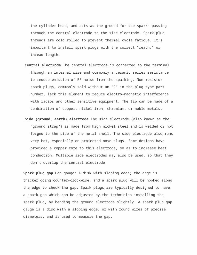
Q.2. What is the main function of a spark plug? Draw a neat sketch of a spark plug and explain its
various parts.
Ans.2 The spark plug is responsible for providing an electrode gap to produce an ignition to the vapor
packed in fuel-air mixture. It also provides the gas-tight path starting from the high-tension lead wire
to the supplied electrode gap. At great engine velocity, about 20,000 volts must be produced in
roughly 40 times every second without any dripping to the ground. The function of a spark plug is to
produce the sparks necessary to ignite the gas and air in the engine, initiating a combustion reaction
that provides energy to run the automobile. Spark plugs are designed to fit perfectly into each
cylinder of the motor. Spark plugs also transfer heat away from the combustion chamber. Basically
this is what happens: the spark plugs are placed at the top of the cylinder head in most of engine
types, the piston first travels down the cylinder, drawing in a mixture of fuel and air. The piston then
goes back up toward the spark plug, compressing the mixture. At the very last second, when the
piston is at its fullest reach on the top of the cylinder, the spark plug sparks and ignites the mixture.
The piston is forced back down to create power for the vehicle by way of crank shafts and drive
shafts to the wheels. At that point, the process of firing the engine ends and starts all over again to
continuously give power to the vehicle.

Parts of the plug
Terminal The top of the spark plug contains a terminal to connect to the ignition system. The exact
terminal construction varies depending on the use of the spark plug. Most passenger car spark plug
wires snap onto the terminal of the plug, but some wires have eyelet connectors which are fastened
onto the plug under a nut. Plugs which are used for these applications often have the end of the
terminal serve a double purpose as the nut on a thin threaded shaft so that they can be used for either
type of connection.
Insulator The main part of the insulator is typically made from sintered alumina a very hard ceramic
material with high dielectric strength, printed with the manufacturer's name and identifying marks,
then glazed to improve resistance to surface spark tracking. Its major functions are to provide
mechanical support and electrical insulation for the central electrode, while also providing an
extended spark path for flashover protection. This extended portion, particularly in engines with
deeply recessed plugs, helps extend the terminal above the cylinder head so as to make it more
readily accessible.
Insulator tip Two spark plugs in comparison views in multiple angles, one of which is consumed
regularly, while the other has the insulating ceramic broken and the central electrode shortened, due
to manufacturing defects and / or temperature swing
Seals Because the spark plug also seals the combustion chamber or the engine when installed, seals are
required to ensure there is no leakage from the combustion chamber. The internal seals of modern

plugs are made of compressed glass/metal powder, but old style seals were typically made by the use
of a multi-layer braze.
Metal case/shell The metal case/shell (or the jacket, as many people call it) of the spark plug withstands
the torque of tightening the plug, serves to remove heat from the insulator and pass it on to the
cylinder head, and acts as the ground for the sparks passing through the central electrode to the side
electrode. Spark plug threads are cold rolled to prevent thermal cycle fatigue. It's important to install
spark plugs with the correct "reach," or thread length.
Central electrode The central electrode is connected to the terminal through an internal wire and
commonly a ceramic series resistance to reduce emission of RF noise from the sparking. Non-
resistor spark plugs, commonly sold without an "R" in the plug type part number, lack this element
to reduce electro-magnetic interference with radios and other sensitive equipment. The tip can be
made of a combination of copper, nickel-iron, chromium, or noble metals.
Side (ground, earth) electrode The side electrode (also known as the "ground strap") is made from high
nickel steel and is welded or hot forged to the side of the metal shell. The side electrode also runs
very hot, especially on projected nose plugs. Some designs have provided a copper core to this
electrode, so as to increase heat conduction. Multiple side electrodes may also be used, so that they
don't overlap the central electrode.
Spark plug gap Gap gauge: A disk with sloping edge; the edge is thicker going counter-clockwise, and a
spark plug will be hooked along the edge to check the gap. Spark plugs are typically designed to have a
spark gap which can be adjusted by the technician installing the spark plug, by bending the ground
electrode slightly. A spark plug gap gauge is a disc with a sloping edge, or with round wires of precise
diameters, and is used to measure the gap.
Tip protrusion Different spark plug sizes. The left and right plug are identical in threading, electrodes,
tip protrusion, and heat range. The centre plug is a compact variant, with smaller hex and porcelain
portions outside the head, to be used where space is limited. The rightmost plug has a longer
threaded portion, to be used in a thicker cylinder head.
OR
Q.2. With a neat sketch explain the magneto ignition system.
Ans.2 Magneto ignition system is a special type of ignition system with its own electric generator to
provide the required necessary energy for the vehicle (automobile) system. It is mounted on the

engine and replaces all components of the coil ignition system except the spark plug. A magneto,
when rotated by the engine, is capable of producing a very high voltage and doesn’t need a battery as
source of external energy. The high tension magneto ignition system incorporates the windings to
generate the primary voltage as well as to set up the voltage and thus does not require to operate the
spark plug.
Figure : Schematic Diagram of Magneto Ignition System
Magneto ignition system can be either rotating armature type or rotating magneto type.
1. In the first type, the armature consisting of the primary and secondary windings all rotate between
the poles of a stationary magnet.
2. In the second type, the magnet revolves and windings are kept stationary.
3. The third type of magneto called the polar inductor type in use. In the polar inductor type
magneto, both the magnet and the windings remain stationary but the voltage is generated by
reversing the flux field with the help of soft iron polar projections, called inductors.
The working principle of the magnetic ignition system is same as that of the coil ignition system. With
the help of a cam, the primary circuit flux is changed and a high voltage is produced in the secondary
circuit. The variation of the breaker current with speed for the coil ignition system and the magnetic
ignition system is shown in the graph 1. It can be seen that since the cranking speed at stat is low the
current generated by the magneto is quite small. As the engine speed increases the current flow also
increases. Thus, with magneto, there is always a starting difficulty and sometimes a separate battery

is needed for starting. The magneto ignition system is best suitable at high speeds and is widely used
in automobiles like sports and racing cars, aircraft’s engines etc.
Q.3. What are the various desired properties of a lubricant and explain how additives help to achieve the
desired properties.
Ans.3 A lubricant is a substance introduced to reduce frictional force and heat generation between the
surfaces in mutual contact, when the surfaces move.
A good lubricating oil generally possess the following characteristics:
1. Suitable Viscosity: The viscosity of oil should not change with rise in temperature.
2. Oilness: It ensures the adherence to the bearings and spread over the surface. This property
makes oil smooth and very important in boundary lubrication.
3. Strength: The lubricant must have high strength to avoid metal contact and seizure under heavy
loads.
4. Chemical Stability: The lubricant should not react with surfaces and any deposit in the cylinder.
5. Pour Point: It should be low to allow the flow of lubricant at low temperature to the oil pump.
6. Flash Point and Fire Point: The lubricating oil should not burn inside the cylinder, otherwise it
will leave heavy deposit and poisonous exhaust. Therefore, the flash point and fire point of the
lubricating oil must be high.
7. Neutralization: The oil should not have a tendency to form deposits by reacting with air, water,
fuel or the products of combustion.
8. Cleaning: The oil should act as cleaning agent inside the engine and should carry any deposits
with it. It should also have non-foaming characteristics, low cost and be non-toxic.
Need of Additives :
In applications where hydrodynamic lubrication films are formed there is no need of additives, but
to counteract high speed, high temperature, high load, etc. additives are required.
Detergent additives :
Detergents, like dispersants, are blended into lubricants to remove and neutralize harmful products.
Detergents form a protective layer on the metal surfaces to prevent deposition of sludge and

varnish. The metallic basis for detergents includes barium, calcium, magnesium and sodium. In
engines, this can reduce the amount of acidic materials produced. Detergent additives are soaps
of high molecular weight, soluble in oil (functional) group attracts particulate contaminants in
the lubricant.
Dispersants additives :
Purpose of dispersant additives is to suspend or disperse harmful products (i.e. dirt, water, fuel,
process material, and lube degradation products such as sludge, varnish, oxidation products)
within the lubricant. These compounds have a large hydrocarbon tail and a “polar group” head.
Tail section serves as a solubilize in the base oil, while polar (functional) group attracts
particulate contaminants in the lubricant.
Anti-wear additives :
• Prevent metal to metal contact. Useful under lighter to moderate loads (bearings).
• Anti-wear additives typically contain zinc and phosphorus compounds. With increase in load anti-
wear additive may be ineffective and EP additives are required in heavy load applications such as
gearboxes.
• Chemical active —- Coat a protective layer on the metal surface by chemical decomposition and
absorption. Zinc dithiophosphate (ZDP): Probably the most widely used in formulated engine oils,
also acts as a corrosion inhibitor and antioxidant.
Anti-foaming agents (Foam Inhibitors) :
Lubricant foams due to agitation and aeration that occurs during operation. Foaming interfere with
flow rate and heat transfer and increase oxidation.
Pour point depressants :
Pour point depressants reduce the pour point and are therefore required when operating at lower
temperatures. Pour point is the lowest temperature at which the lubricant will flow. Waxy crystals
are formed at lower temperature, therefore additives methacrylate polymers, polyalkylphenol esters.
Encapsulate crystal so that it cannot grow.

OR
Q.3. What are the advantages and limitations of water cooled system?
Ans.3 In a liquid-cooling system, water or other solutions flow through the water jacket around the
cylinder and cylinder head to absorb the heat. The hot liquid coming out of the water jacket is
cooled in the radiator, where circulated air absorbs the heat from the radiator. The cold liquid
coming out of the radiator is again pumped to the water jacket for absorbing heat.
Advantages of Liquid-cooling System:
Liquid-cooling system is efficient as compared to air-cooling system.
Fuel consumption of liquid-cooled engines is less than that of air-cooled engines.
Liquid-cooled engines require less frontal area.
For water-cooled engines, the cooling system can be located conveniently anywhere on the
automobile. Some vehicles have it at the rear, while in air cooled engines, it is not possible.
Size doesn’t pose a serious concern in the water cooled engine, while in the high-output engines,
it is difficult to circulate the correct quantity of air in an air-cooled engine.
Limitations of liquid Cooled System:
It requires pure water supply for proper functioning.
The pump absorbs considerable power and it reduces the output of the engine.
In case of failure of cooling system, the engine may get a serious damage.
Cost of the system is considerably high.
The system requires continuous maintenance of its parts.
Q.4. What are the limitations of supercharging in an IC engine? Compare the various scavenging
methods.

Ans.4 Superchargers are pressure boosting devices (compressors) which increase the pressure of the air
before letting it get into cylinder of the internal combustion engine . And the process of increasing
the pressure OR forcing more air to get into engine is called as supercharging.
Limitations:-
Draws power from engine. Though the overall mechanical efficiency is increased but it consumes
power from the engine. The same job is done by a turbocharger without consuming extra power.
Increased heat generation. The engine should have proper heat dissipation systems as well as it
should be able to withstand thermal stresses.
Induces stress. The engine must hold up against the high pressure & bigger explosions generated
in the cylinder. If the engine is not designed considering these stresses, it may damage the piston
head.
Scavenging methods
Scavenging is the removal of exhaust gases by blowing in fresh air. Charging is the filling of the
engine cylinder with a supply or charge of fresh air ready for compression. With supercharging a
large mass of air is supplied to the cylinder by blowing it in under pressure. With two-stroke
cycle engines this overlap is limited and some slight mixing of exhaust gases and incoming air
does occur.
A number of different scavenging methods are in use in slow-speed two-stroke engines. In each
the fresh air enters as the inlet port is opened by the downward movement of the piston and
continues until the port is closed by the upward moving piston. The flow path of the scavenge air
is decided by the engine port shape and design and the exhaust arrangements.
Three basic systems are in use: the cross flow, the loop and the uniflow. All modern slow-speed
diesel engines now use the uniflow scavenging system with a cylinder-head exhaust valve.

Fig:Crossflow scavenging
In cross scavenging the incoming air is directed upwards, pushing the exhaust gases before it. The
exhaust gases then travel down and out of the exhaust ports. Figure above illustrates the process.
In loop scavenging the incoming air passes over the piston crown then rises towards the cylinder
head. The exhaust gases are forced before the air passing down and out of exhaust ports located
just above the inlet ports. The process is shown in Figure below.
With uniflow scavenging the incoming air enters at the lower end of the cylinder and leaves at the top.
The outlet at the top of the cylinder may be ports or a large valve. The process is shown here.

OR
Q.4. What is a free piston engine and what are its characteristics?
Ans.4 A free-piston engine is a linear, 'crankless' internal combustion engine, in which the piston
motion is not controlled by a crankshaft but determined by the interaction of forces from
the combustion chamber gases, a rebound device (e.g., a piston in a closed cylinder) and a load
device (e.g. a gas compressor or a linear alternator). The purpose of all such piston engines is to
generate power. In the free-piston engine, this power is not delivered to a crankshaft but is instead
extracted through either exhaust gas pressure driving a turbine, through driving a linear load such as
an air compressor for pneumatic power, or by incorporating a linear alternator directly into the
pistons to produce electrical power. The basic configuration of free-piston engines is commonly
known as single piston, dual piston or opposed pistons, referring to the number of combustion
cylinders. The free-piston engine is usually restricted to the two-stroke operating principle, since a
power stroke is required every fore-and-aft cycle.
A Free Piston Engine is a type of internal combustion engine used to generate electrical power from the
combustion of a fuel. Unlike conventional engines there is no crankshaft or mechanical powertrain to
transmit power and govern piston motion. Instead, pistons are free to move back and forth under the

action of combustion and bounce chamber pressure. A linear electrical machine is coupled directly to
each piston to generate power. The same electrical machine can also control piston position dynamically
to optimize compression ratio in real time and compensate for cycle-to-cycle variability.
Characteristics of free piston engine
High efficiency Free piston engine developers have reported significant efficiency gains, which arise for
a variety of reasons. Firstly, in a free piston engine, the piston accelerates away from the ‘top dead centre’
position much more rapidly than in a conventional engine, reducing the time for heat losses into the
chamber walls when combustion temperatures are at their peak. Secondly, precise control of piston
motion permits advanced combustion cycles such as ‘homogeneous charge compression ignition’ (HCCI)
to be realised. This results in more of the fuel energy being converted into useful working pressure.
Thirdly, the elimination of the mechanical drivetrain removes several components and surfaces that are
directly responsible for friction and heat losses in conventional engines.
Low emissions In theory, an internal combustion engine combines oxygen with just the right amount of
fuel to produce carbon dioxide and water, and nothing else. In practice, not all of the fuel is completely
burned, and some oxygen molecules combine with nitrogen in the air rather than with the fuel. Both of
these undesired processes result in harmful tailpipe emissions. In a conventional engine, these processes
are controlled mainly by varying the amount of fuel that is introduced. In a free piston engine, the
compression ratio provides a means to control the amount of energy that each fuel and oxygen molecule
has. This additional control will make it possible for free piston engine developers to adopt much more
effective emissions reduction strategies without compromising engine performance and efficiency.
Fuel-flexibility The variable compression ratio made possible by ‘digital piston motion’ in a free piston
engine can be tailored according to the type of fuel that is being used, whether this changes day-to-day (as
is the case with vehicles using bio-ethanol fuel blends) or hour-tohour (as can be the case with static
biogas generator sets in Europe)
Low noise & vibration Elimination of rotating parts greatly reduces the scope for vibrations to be
transmitted from the engine mountings and into the surrounding structure. A two cylinder opposed free
piston engine is intrinsically fully balanced, and compressors using this arrangement have been renowned
for their quiet operation.
Oil-free With lower side loads on the piston skirt, oil lubrication can be replaced with gas bearings. Not
only does this approach eliminate the need for oil changes, it reduces the engine’s heat and friction losses,
reduces hydrocarbon emissions, and in high volume manufacture will also help to reduce the engine’s
cost.
Low cost The powertrain from piston to generator is greatly simplified through the elimination of the
crankshaft, gudgeon pins, connecting rods and flywheel. Structural housing components can be extruded,
rather than cast, further reducing cost.
Compact format The simplification that reduces a free piston engine’s cost also allows more compact
engines that can be readily downsized to 1-10kWe scales