Embed Size (px)
Citation preview

Integrating Ambient Light Sensors with Computers Running Windows 10: Creator’s Update
Considerations for Interfacing Ambient Light Sensors with Windows.
May 18, 2017
Abstract
This paper provides information about ambient light sensor (ALS) features in the Windows 10 Creators Update operating system. It provides guidelines for hardware manufacturers and original equipment manufacturers (OEMs) to integrate ALS hardware with computers that use the adaptive brightness feature and with applications that use light sensor data.
References and resources discussed here are listed at the end of this paper.
The current version of this paper is maintained on the Web at: Integrating Ambient Light Sensors with Computers Running Windows 10 Creators Update
Disclaimer: This document is provided “as-is”. Information and views expressed in this document, including URL and other Internet website references, may change without notice. Some information relates to pre-released product which may be substantially modified before it’s commercially released. Microsoft makes no warranties, express or implied, with respect to the information provided here. You bear the risk of using it.
This document does not provide you with any legal rights to any intellectual property in any Microsoft product. You may copy and use this document for your internal, reference purposes.
© 2017 Microsoft. All rights reserved.

Integrating Ambient Light Sensors with Computers Running Windows 10 Creators Update
Document HistoryDate Change
May 18, 2017 Updates for clarity and consistency
April 18, 2017 Updates for alignment with Windows 10 Creators Update RTM
March 22, 2017 Include sample ALR curve and sample lux-to-nits dataset.
March 6, 2017 Corrected registry key path and name. Add information around upgrade behavior from Windows 10 Anniversary Update and early releases.
February 13, 2017 Updates including sample ALR curve and clarification of required registry keys.
January 31, 2017 Updates for alignment with Windows 10 Creators Update
September 28, 2012 Updates to reflect rebranding; updated Light Sensor Features, Ambient Light Sensor Integration Checklist, Understanding Adaptive Brightness Support in Windows 8, Integrating Light Sensors with Computer Hardware, and ALR Curve Type.
July 31, 2012 Updates for alignment with Windows 8 RTM
June 13, 2012 First publication for Windows 8
© 2017 Microsoft. All rights reserved.

Integrating Ambient Light Sensors with Computers Running Windows 10 Creators Update
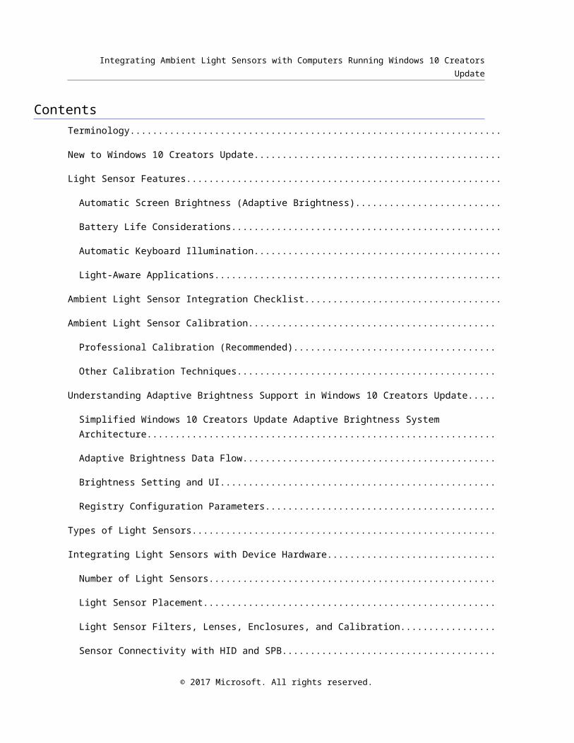
ContentsTerminology.................................................................................................................................................
New to Windows 10 Creators Update..........................................................................................................
Light Sensor Features..................................................................................................................................
Automatic Screen Brightness (Adaptive Brightness)...............................................................................
Battery Life Considerations......................................................................................................................
Automatic Keyboard Illumination.............................................................................................................
Light-Aware Applications.........................................................................................................................
Ambient Light Sensor Integration Checklist.................................................................................................
Ambient Light Sensor Calibration..............................................................................................................
Professional Calibration (Recommended).............................................................................................
Other Calibration Techniques................................................................................................................
Understanding Adaptive Brightness Support in Windows 10 Creators Update..........................................
Simplified Windows 10 Creators Update Adaptive Brightness System Architecture..............................
Adaptive Brightness Data Flow..............................................................................................................
Brightness Setting and UI......................................................................................................................
Registry Configuration Parameters........................................................................................................
Types of Light Sensors..............................................................................................................................
Integrating Light Sensors with Device Hardware.......................................................................................
Number of Light Sensors.......................................................................................................................
Light Sensor Placement........................................................................................................................
Light Sensor Filters, Lenses, Enclosures, and Calibration.....................................................................
Sensor Connectivity with HID and SPB.................................................................................................
Optimizing Display Brightness Steps and Transitions................................................................................
Tuning and Configuring Adaptive Brightness Behavior..............................................................................
Lux-to-Nits Relationship........................................................................................................................
Ambient Light Response (ALR) Curve...................................................................................................
© 2017 Microsoft. All rights reserved.
Integrating Ambient Light Sensors with Computers Running Windows 10 Creators Update
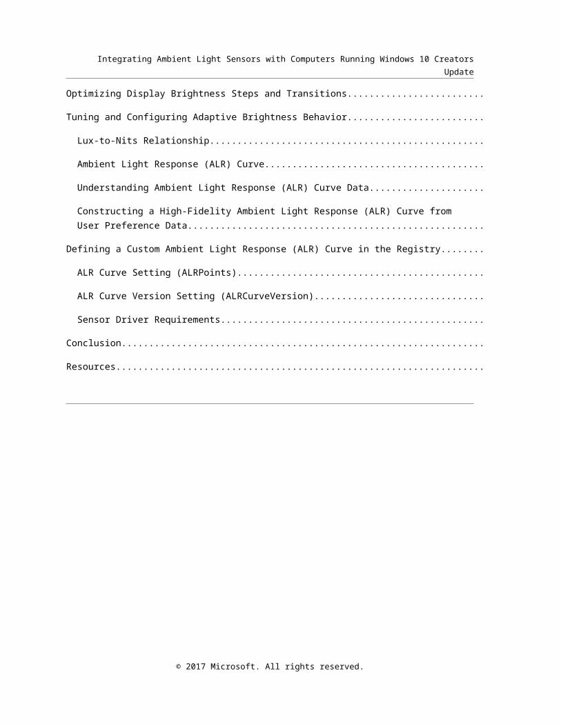
Understanding Ambient Light Response (ALR) Curve Data..................................................................
Constructing a High-Fidelity Ambient Light Response (ALR) Curve from User Preference Data..........
Defining a Custom Ambient Light Response (ALR) Curve in the Registry.................................................
ALR Curve Setting (ALRPoints).............................................................................................................
ALR Curve Version Setting (ALRCurveVersion)....................................................................................
Sensor Driver Requirements.................................................................................................................
Conclusion.................................................................................................................................................
Resources..................................................................................................................................................
© 2017 Microsoft. All rights reserved.
Integrating Ambient Light Sensors with Computers Running Windows 10 Creators Update
TerminologyTerm Definition
ABS Automatic brightness service
ALS Ambient light sensor
ALR Ambient light response
SPB Simple peripheral bus (low power bus such as I2C)
Light pipe A light directing device (such as a clear plastic extrusion)
HLK Windows Hardware Lab Kit (formerly called HCK, Windows Hardware Certification Kit)
HLK Test A test that validates device firmware or drivers (device test) or a test that validates system-level features (system test)
Adaptive brightness
Automatic screen brightness control using ALS in Windows
ALR curve Ambient light response curve: a collection of points that defines the relationship between light levels (LUX) and offsets that are applied to a user’s screen brightness preference for adaptive brightness
Nit Unit of luminance: 1 nit = 1 candela per square meter. Quantifies the brightness output of a display.
Lux Unit of illuminance: 1 lux = 1 lumen per square meter. Quantifies the brightness of the environment; measured by an ALS sensor.
© 2017 Microsoft. All rights reserved.

Integrating Ambient Light Sensors with Computers Running Windows 10 Creators Update
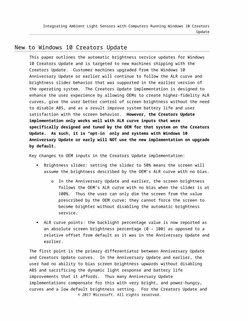
New to Windows 10 Creators UpdateThis paper outlines the automatic brightness service updates for Windows 10 Creators Update and is targeted to new machines shipping with the Creators Update. Customer machines upgraded from the Windows 10 Anniversary Update or earlier will continue to follow the ALR curve and brightness slider behavior that was supported in the earlier version of the operating system. The Creators Update implementation is designed to enhance the user experience by allowing OEMs to create higher-fidelity ALR curves, give the user better control of screen brightness without the need to disable ABS, and as a result improve system battery life and user satisfaction with the screen behavior. However, the Creators Update implementation only works well with ALR curve inputs that were specifically designed and tuned by the OEM for that system on the Creators Update. As such, it is “opt-in” only and systems with Windows 10 Anniversary Update or early will NOT use the new implementation on upgrade by default.
Key changes to OEM inputs in the Creators Update implementation:
Brightness slider: setting the slider to 50% means the screen will assume the brightness described by the OEM’s ALR curve with no bias.
o In the Anniversary Update and earlier, the screen brightness follows the OEM’s ALR curve with no bias when the slider is at 100%. Thus the user can only dim the screen from the value prescribed by the OEM curve; they cannot force the screen to become brighter without disabling the automatic brightness service.
ALR curve points: the backlight percentage value is now reported as an absolute screen brightness percentage (0 – 100) as opposed to a relative offset from default as it was in the Anniversary Update and earlier.
The first point is the primary differentiator between Anniversary Update and Creators Update curves. In the Anniversary Update and earlier, the user had no ability to bias screen brightness upwards without disabling ABS and sacrificing the dynamic light response and battery life improvements that it affords. Thus many Anniversary Update implementations compensate for this with very bright, and power-hungry, curves and a low default brightness setting. For the Creators Update and future releases, OEMs are strongly encouraged to create realistic ALR curves which perform well with the default brightness setting of 50%. The Brightness Setting and UI section of this document contains more information on the new brightness slider behavior in the Creators Update.
Note to phone OEMs using auto-brightness keys under [HKLM\Software\OEM\Autobrightness]:
The ABSPercentIntensityMapping and ABSRangeMilliLuxMapping registry keys are deprecated in the Creators Update and will only be used as the ambient light response curve if ALRPoints is not present on the system. DimBrightness and TransitionDelay registry keys, under the same path, are not supported in the Creators Update. New devices with the Creators Update must use the ALRPoints registry key.
© 2017 Microsoft. All rights reserved.
Integrating Ambient Light Sensors with Computers Running Windows 10 Creators Update
Light Sensor FeaturesAn ambient light sensor (ALS) is used to measure the lighting conditions of the device’s current environment. When a device is aware of the surrounding lighting conditions, it can use that information to enhance the user experience and save battery life in several ways. Light sensors can support the following types of scenarios:
Automatic screen brightness Automatic Keyboard illumination (Needs additional driver support) Light-aware applications
Automatic Screen Brightness (Adaptive Brightness)What a user perceives as optimal screen brightness on their device is a function of the current lighting conditions and other factors, such as how the user’s eyes adjust to lighting conditions over time. In low-light conditions, such as in a dark room, the optimal screen brightness is a lower value than in a brightly lit room or daylight outdoor conditions. As surrounding lighting levels increase, the optimal screen brightness needs to increase. In varying lighting conditions, users prefer that the device automatically adjust its own screen brightness. In Windows, this is known as automatic or adaptive brightness.
Screen display output is measured in luminance using units of nits. This is defined as the intensity of light emitted from a surface per unit area in a given direction. The ALS measures illuminance, in units of lux, and measures how much light is incident on the device. The adaptive brightness algorithm in Windows takes the illuminance reported by the ALS as input and calculates an appropriate screen brightness output based on OEM customizations, user preferences, and system power considerations.
The adaptive brightness algorithm in Windows operates based on the following principles:
Consistently present the optimal backlight level in any lighting condition
Avoid distracting or jarring backlight transitions – especially important in low light environments
Conserve battery power – do not drive backlight higher than it needs to be for a given lighting condition
Allow the user to easily and quickly override the algorithm using the brightness slider
Quickly increase display brightness when moving from a dark to bright environment
Slow, non-distracting decrease in display brightness when moving to a dark environment
Hysteresis prevents backlight from adjusting too frequently in a dark environments
© 2017 Microsoft. All rights reserved.

Integrating Ambient Light Sensors with Computers Running Windows 10 Creators Update
In Windows 10 Creators Update, the adaptive brightness algorithm is converged across mobile and desktop devices. Different device types, screens and sensors will need to be individually calibrated to the specific hardware properties and customer use cases, but the underlying algorithm and customization points are converged across mobile and desktop Windows. This document covers how to design and validate an appropriate brightness curve for your device.
Battery Life ConsiderationsIn addition to enhancing the viewing experience, an automatic display brightness control can increase battery life. With display backlight often consuming around 40% of the total system power budget, it is critical that the backlight is never brighter than the user needs. By dimming the display when it is appropriate, a device can reduce power consumption while primarily enhancing user experience and readability automatically in extreme lighting conditions.
A suboptimal ALR curve will decrease battery life by putting the screen in a brighter than needed state for the given lighting conditions. Please follow the guidance in this document for constructing and calibrating an optimized ALR curve for your device. It is critical to the device’s battery life that the ALR curve be tuned to minimize unnecessary power consumption.
Automatic Keyboard IlluminationTraditional keyboards are typically not visible in dark lighting conditions. To resolve this problem, either top illumination or reverse illumination can help users see the keyboard when they type. To optimize power consumption, hardware manufacturers can use an ALS to control the intensity of the illumination based on the lighting conditions. This feature is not supported by default on Windows and needs additional drivers from the device manufacturer to adjust keyboard brightness.
Light-Aware ApplicationsTo ensure a good user experience across all lighting conditions, Windows automatically adjusts screen brightness (see Automatic Screen Brightness). However, applications can leverage the detected lighting conditions to adapt their behavior and alter their user interface (UI) to maximize contrast and legibility. Combining applications with adaptive brightness can make devices more usable in adverse lighting conditions.
For more information about how to build light-aware applications, see Implementing Light-Aware UI Using the Windows Sensor and Location Platform.
In Windows, ALS can be accessed by applications via the Windows Runtime API. ALS functionality is exposed by the Windows.Devices.Sensors.LightSensor class. For more information, see the LightSensor class.
© 2017 Microsoft. All rights reserved.

Integrating Ambient Light Sensors with Computers Running Windows 10 Creators Update
Ambient Light Sensor Integration ChecklistThe following high-level checklist is for developers integrating sensor hardware into devices. The rest of this document describes the process and background information in detail.
Select a suitable light sensor. To ensure the best experience the ALS should have a granularity of at most 1 lux when the ambient light is below 25 lux and a granularity of at most 4% of the ambient light when it is above 25 lux. This enables the adaptive brightness algorithm to perform smooth screen brightness transitions.
Select optimized placement for the light sensor in your device enclosure (see Optimized Placement for ALS).
Perform per-model calibration taking into account all factors (coatings, light pipe, sensor configuration, placement, and so on). This should be performed using professional, pre-calibrated light meters (see Ambient Light Sensor Calibration).
Integrate the sensors on to the device in one of the supported ways.
o Leverage the inbox HID Sensor class driver (connect the device over USB or I2C HID transport)
Test the complete device as a light measurement instrument. Use various types of test lighting (incandescent, fluorescent, LED, etc.) at various intensities and compare values reported through the sensor platform with a high-quality industrial/scientific light meter (meter should measure light incident on display of device).
Construct an ambient light response (ALR) curve based on the guidance in the Tuning and Configuring Adaptive Brightness Behavior section.
Test the device (and third- party drivers, if pertinent) with the Windows Hardware Lab Kit (HLK) device requirements and related tests. Ensure that it runs correctly and passes all pertinent test cases.
Ensure that OEM, ODM, and IHV participate in mechanical design reviews for each major revision of device hardware (EV, DV, MP, and so on.). Ensure that sensor implementation is optimized mechanically, optically, and from an electrical engineering perspective.
Make sure that the display implementation is optimized. Specifically, do the following:
o Ensure that display is capable of dimming smoothly across the ALR zones.
o Make sure that sufficient display brightness levels are exposed to ensure smooth dimming. At least 100 levels are suggested.
Test light sensors and adaptive brightness by doing the following:
o Make sure that the SensorService service is started.
o Enable auto-brightness and set the slider to Suggested (50%).
o Validate that the display brightness changes when the lighting changes.
© 2017 Microsoft. All rights reserved.

Integrating Ambient Light Sensors with Computers Running Windows 10 Creators Update
o Use a light dimmer to slowly ramp environmental light up and down and ensure that the lux values are smoothly ramping up and down. Coarse/discrete light changes will result in sub-optimal screen brightness response and should be avoided.
o Use a professional lux meter and ensure that the ALS readings are accurate. At a minimum verify the following points: 0, 10, 100, 500 and 1000 lux.
o Test behavior with users to validate ALR data meets user expectations.
o Ensure that all Windows HLK device and system tests pass.
Ambient Light Sensor Calibration
Professional Calibration (Recommended)Calibration of the ALS in the integrated system using professional, pre-calibrated sensors in a controlled lighting environment is highly recommended. These pre-calibrated sensors, often called "luminance meters" or "brightness meters," are available for purchase from electronic equipment vendors and online retailers.
Other Calibration TechniquesDetails on additional ALS monitoring and calibration tools is coming soon. Please look for an update to this document with more information.
Understanding Adaptive Brightness Support in Windows 10 Creators UpdateIn Windows 10 Creators Update, automatic brightness control is supported and turned on by default.
The following components for adaptive brightness are included in Windows 10 Creators Update:
In-box class drivers for ALS
o HID Sensor Driver: A HID sensor class driver for an ALS that is connected behind a sensor microcontroller (MCU, or has HID support onboard the ALS chip).
A sensor-monitoring Windows service that consumes light sensor data and then affects the display brightness.
Settings in the System>Display page of the Settings app to enable or disable adaptive brightness and modify the current screen brightness.
Adaptive brightness registry configuration parameters.
The following subsections examine how these components support adaptive brightness.
Simplified Windows 10 Creators Update Adaptive Brightness System Architecture© 2017 Microsoft. All rights reserved.

Integrating Ambient Light Sensors with Computers Running Windows 10 Creators Update
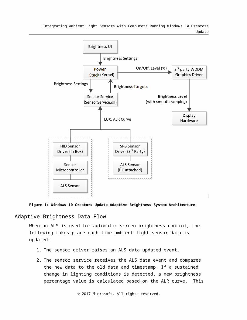
Figure 1: Windows 10 Creators Update Adaptive Brightness System Architecture
Adaptive Brightness Data FlowWhen an ALS is used for automatic screen brightness control, the following takes place each time ambient light sensor data is updated:
1. The sensor driver raises an ALS data updated event.
2. The sensor service receives the ALS data event and compares the new data to the old data and timestamp. If a sustained change in lighting conditions is detected, a new brightness percentage value is calculated based on the ALR curve. This value is adjusted up or down based on the user’s current brightness preference and passed to the kernel.
3. The kernel receives the updated brightness percentage value and sets the new brightness level via WDDM.
© 2017 Microsoft. All rights reserved.

Integrating Ambient Light Sensors with Computers Running Windows 10 Creators Update
4. The WDDM driver receives the new brightness level and transitions to the new brightness level.
The following section discusses the various ALS-related components that make up this system .
Brightness Setting and UIAn on/off setting as well as a brightness slider bar for adaptive brightness is presented in the Settings application under System>Display. In Windows 10 Creators Update, users can adjust their current screen brightness preference by using the brightness slider, and also can toggle adaptive brightness on or off.
Figure 2: Display settings for adaptive brightness in Settings app
Beginning in the Creators Update, the Change brightness slider’s behavior is redefined when a system is opted-in to use the new ALR version:
The adaptive brightness algorithm first calculates the optimal output brightness based on the ALR curve defined for the device. This brightness output is then scaled by the brightness slider as follows:
- At the midpoint of the slider – the “Suggested” level – no scaling is applied; the ALR curve is weighted at 100%.
- As the slider increases from 50% to 100% the brightness is scaled proportionally upwards. More weight is given to the slider value and less to the algorithm as it approaches 100% such that at 100% the screen is set to maximum brightness.
- As the slider decrease from 50% to 0% the scaling is reversed, resulting in minimum screen brightness at 0%.
© 2017 Microsoft. All rights reserved.
Integrating Ambient Light Sensors with Computers Running Windows 10 Creators Update
This behavior allows the user to easily scale the screen brightness up or down to a desired level while maintaining the benefit of automatic adaptation to the ambient light environment. It also allows for an easy way to override the algorithm to force maximum or minimum screen brightness as needed. This functionality is a fundamental change from the implementation in the Anniversary Update and earlier OS editions where a brightness slider setting of 100% equaled the screen brightness value as dictated by the OEM’s ALR curve and the user was only able to scale this value downward. The previous implementation did not allow the user to scale the screen brightness upwards from this value without disabling automatic brightness functionality and taking manual control.
This user control is also available via the Quick Actions menu (Figure 3), which allows the user to select between 5 preset levels: Darkest, Darker, Suggested, Brighter, and Brightest, which correlate with 0, 25, 50, 75 and 100 percent respectively. The Change brightness slider found in Settings->System->Display, adjusts in increments of 1 percent yielding finer grained control than the Quick Actions toggle. Note that in the Creators Update, similar to previous releases, two separate brightness slider levels are maintained for AC (external power) and DC (battery power). This enables the user to, for example, save additional power when operating on battery by setting a low brightness slider value, but return to a higher brightness level when external power is available.
Figure 3: Quick Actions brightness control.
© 2017 Microsoft. All rights reserved.

Integrating Ambient Light Sensors with Computers Running Windows 10 Creators Update
Another toggle under System->Battery in the Settings app allows the system to dim the screen further than it normally would in the current lighting environment when the system is running low on battery power and battery saver mode is enabled. See Figure 4 below for this setting.
Figure 4: Battery saver mode settings
Registry Configuration ParametersWindows 10 Creators Update provides the following registry parameter that can be used to fine-tune the behavior of the adaptive brightness feature:
An ALR curve, which is a collection of data that determines how the brightness of the screen changes, based on lighting conditions.
© 2017 Microsoft. All rights reserved.
Integrating Ambient Light Sensors with Computers Running Windows 10 Creators Update
For more information about this parameter, see Tuning and Configuring Adaptive Brightness Behavior later in this document.
Types of Light SensorsAmbient light sensors come in two fundamental types:
Analog light sensors are connected to an embedded controller with an A/D converter and require firmware that can accurately interpret the light sensor data and compensate for various conditions and phenomena that affect readings. Some examples of these phenomena include infrared (IR) light rejection and light frequency compensation. For example, fluorescent lights vary in intensity with the frequency of the AC power that is supplied to the fixture. Analog sensors are typically very inexpensive.
Digital light sensors are more expensive than analog sensors but have advantages over analog light sensors. These sensors can automatically compensate for various conditions and phenomena. Digital light sensors are also extremely compact.
Regardless of which type of light sensor you choose, ensure accurate readings are taken and exposed to the system.
Integrating Light Sensors with Device HardwareSelecting a suitable ALS device is critical. Several things can greatly affect what can be done with the information that the light sensors provide. These considerations include the following:
The type of sensor (analog versus digital). Digital light sensors are preferred.
The accuracy, resolution, and field of view of the sensor.
The dynamic range of the sensor.
IR and ultraviolet (UV) rejection (human eye response).
Supported bus technology (digital only).
The sampling rate (digital only).
Power consumption.
Packaging and placement options.
Although these are all important considerations, two factors warrant special consideration:
Accuracy and resolution: To deliver an optimal user experience for adaptive brightness and light-aware UI in applications, accurate sensor data is required as input. Generally, the more accurate the sensor is, the better the corresponding user experience will be. A good goal for actual ALS calibrated values is a consistent accuracy of within 4 percent of actual lighting conditions.
Dynamic range: The dynamic range of a light sensor is the ratio between the largest and smallest values that the sensor can report, and defines range of lighting environments in which the sensor can be effective. A low dynamic range light sensor limits the environments in which
© 2017 Microsoft. All rights reserved.

Integrating Ambient Light Sensors with Computers Running Windows 10 Creators Update
it can be used. Because applications can be light-aware in Windows, outdoor lighting conditions are an important consideration.
Granularity: The lux reading should have a granularity of at most 1 lux below 25 lux and a granularity of at most 4% above 25 lux.
Table 1. Common lighting conditions and approximate illuminance valuesLighting condition Illuminance (lux)
Pitch black 1
Very dark 10
Dark indoors 50
Dim indoors 100
Normal indoors 300
Bright indoors 700
Dim outdoors (overcast day)
1,000
Sunlight outdoors 15,000
Direct sunlight 100,000
Number of Light SensorsGenerally, the more ALSs that are available to measure a lighting condition, the better the estimate of the actual illuminance. As a practical matter, each light sensor adds cost and uses space on the surface of the device.
It is important that manufacturers strive for a solution that provides the system with the most accurate ambient light sensing capability. Inexpensive solutions may rely on a single sensor, but high end hardware can rely on a sensor array to provide the best possible measure. If an OEM chooses to implement multiple ALS sensors (to address issues like a hand or shadow obscuring the ALS), the OEM should expose one logical (consolidated) ALS to the OS and report the most accurate data.
Light Sensor PlacementCorrect placement of light sensors is another important aspect of good system design. The goal of the ALS is to measure the brightness of the environment as perceived by the user. As such, the “best” theoretical sensor location would be between the eyes of the user. As this isn’t practical,
© 2017 Microsoft. All rights reserved.

Integrating Ambient Light Sensors with Computers Running Windows 10 Creators Update
the real-world optimum placement of the light sensors is generally on the same plane as the display (facing the user). Sensors placed on the display have the advantage of detecting some glare that may occur on the screen.
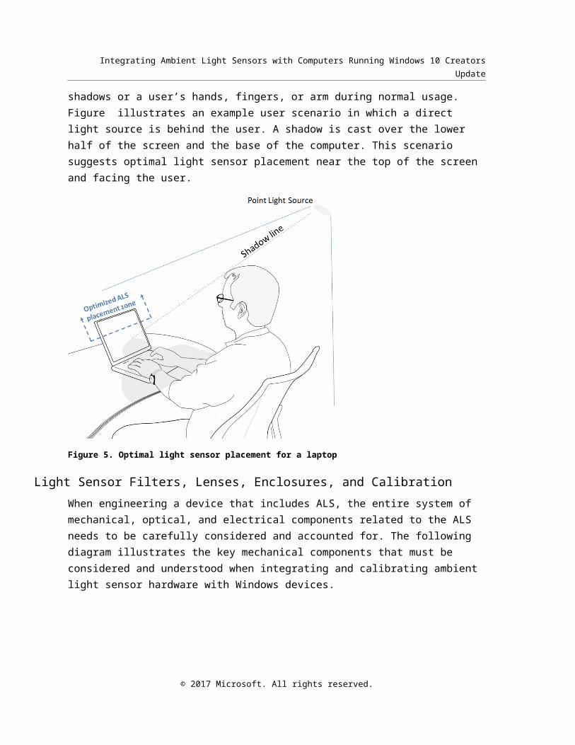
Also, avoid placing the light sensor in areas of the computer that are likely to be obscured from the light source or sources by shadows or a user’s hands, fingers, or arm during normal usage. Figure illustrates an example user scenario in which a direct light source is behind the user. A shadow is cast over the lower half of the screen and the base of the computer. This scenario suggests optimal light sensor placement near the top of the screen and facing the user.
Figure 5. Optimal light sensor placement for a laptop
Light Sensor Filters, Lenses, Enclosures, and CalibrationWhen engineering a device that includes ALS, the entire system of mechanical, optical, and electrical components related to the ALS needs to be carefully considered and accounted for. The following diagram illustrates the key mechanical components that must be considered and understood when integrating and calibrating ambient light sensor hardware with Windows devices.
© 2017 Microsoft. All rights reserved.

Integrating Ambient Light Sensors with Computers Running Windows 10 Creators Update
Figure 6. Cross section of ALS mechanical components
In this diagram we see the following:
1. Glass (outer surface for screen)
2. Ink coating (black border around screen)
3. Light shielding (used to prevent light bleed/leakage)
4. Light pipe1 (gathers and directs light to sensor)
5. Light sensor
6. Motherboard
This diagram references two light levels:
1. LUX1: The incident light level for the surroundings of the device (incident on surface of display). This is what is measured and reported by the ALS sensor via the sensor platform.
1 Note that light pipes are usually not needed, and in many cases may degrade ALS performance. Please consult with the light sensor manufacturer for guidance regarding these kinds of optical components.
© 2017 Microsoft. All rights reserved.

Integrating Ambient Light Sensors with Computers Running Windows 10 Creators Update
2. LUX2: The incident light level on the surface of the ALS. This is not the correct light level to report via the sensor platform as it does not take into account the attenuation2 factor of the optics3.
You should always observe the following: LUX2 < LUX1
The difference between these two lux values is called the attenuation factor. The attenuation factor accounts for the total percentage of light transmittance4 between the top surface of the glass (LUX1) and the bare surface of the ALS sensor (LUX2).This is most drastic when painted optics (glass surface) are used. The OEM, with the support of the sensor IHV, should measure the attenuation factor and correct for it in hardware before exposing the lux value to the operating system.
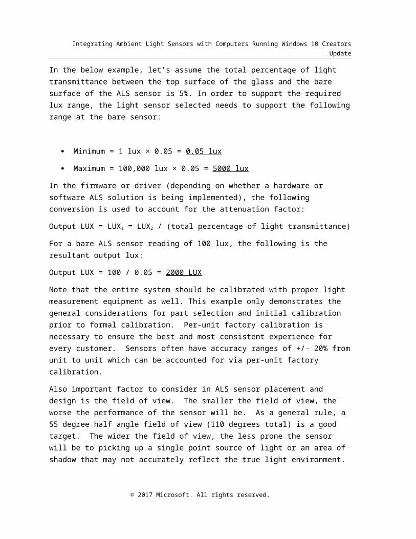
In the below example, let’s assume the total percentage of light transmittance between the top surface of the glass and the bare surface of the ALS sensor is 5%. In order to support the required lux range, the light sensor selected needs to support the following range at the bare sensor:
Minimum = 1 lux × 0.05 = 0.05 lux
Maximum = 100,000 lux × 0.05 = 5000 lux
In the firmware or driver (depending on whether a hardware or software ALS solution is being implemented), the following conversion is used to account for the attenuation factor:
Output LUX = LUX1 = LUX2 / (total percentage of light transmittance)
For a bare ALS sensor reading of 100 lux, the following is the resultant output lux:
Output LUX = 100 / 0.05 = 2000 LUX
Note that the entire system should be calibrated with proper light measurement equipment as well. This example only demonstrates the general considerations for part selection and initial calibration prior to formal calibration. Per-unit factory calibration is necessary to ensure the best 2 Attenuation factor corresponds to how much light is blocked by the various components between the outer surface of the device (typically glass) and the sensing surface of the ALS. Attenuation can be calculated as follows: A = (1 - transmittance)
3 The ALS sensor reports the ambient light intensity that it senses. Due to the transmissibility (attenuation) of the optics, the raw ALS readings report incorrect (attenuated) Lux values and should not be used without correction. The transmissibility is the characteristics of the optics that reduce ambient light intensity and also reject infrared (IR) light. If the optics are painted with ink for visible appearance, an attenuation factor must be used to compensate for the corresponding attenuation.
4 Transmittance is the ratio of the light level at the surface of the ALS divided by the ambient light level surrounding the device.
© 2017 Microsoft. All rights reserved.

Integrating Ambient Light Sensors with Computers Running Windows 10 Creators Update
and most consistent experience for every customer. Sensors often have accuracy ranges of +/- 20% from unit to unit which can be accounted for via per-unit factory calibration.
Also important factor to consider in ALS sensor placement and design is the field of view. The smaller the field of view, the worse the performance of the sensor will be. As a general rule, a 55 degree half angle field of view (110 degrees total) is a good target. The wider the field of view, the less prone the sensor will be to picking up a single point source of light or an area of shadow that may not accurately reflect the true light environment.
Sensor Connectivity with HID and SPBThe following diagrams illustrate how to integrate ALS using the HID protocol, and with an IHV-specific driver for SPB.
Figure 7. HID sensor hardware, driver, and software stack
© 2017 Microsoft. All rights reserved.

Integrating Ambient Light Sensors with Computers Running Windows 10 Creators Update
For more information about integrating sensor hardware via the HID protocol, including HID/I2C, please see HID protocol for sensors.
SPB sensor hardware, driver, and software stack
Figure 8. SPB sensor hardware, driver, and software stack
For more information about integrating sensors via SPB buses, please see SPBAccelerometer WDK sample.
Optimizing Display Brightness Steps and TransitionsThe number of brightness levels that a display device exposes is important. ACPI supports 101 levels of brightness for displays (from 0 to 100 percent in 1-percent increments), though most platforms only support a limited number of entries and interpolate between them. We recommend exposing the full range of supported entries in the _BCL method. The mapping of backlight percentages to luminance values should follow an exponential pattern. Human vision is more sensitive to small changes in screen brightness output (nits) at low light levels, thus more backlight levels should be allocated to the lower brightness range to accommodate smoother transitions. The difference between 1% and 2% in nits should be smaller than the difference from 10% and 11% and so on. This means that 50% of the screen’s maximum luminance will not be mapped to the 50% backlight level.
© 2017 Microsoft. All rights reserved.

Integrating Ambient Light Sensors with Computers Running Windows 10 Creators Update
For a better user experience, map a low, but usable brightness output to the 0% backlight level. The screen must be bright enough at 0% for the user to interact with the UI on the display.
The data representing the screen brightness steps is called the percentage to nits curve. This curve is separate from, but related, to the ALR curve which maps detected ALS brightness, in lux, to brightness percentage. The relationship between ALS input (lux) and screen brightness output (nits) is approximately linear, but given that humans perceive light intensity approximately logarithmically, their respective mappings to brightness percentage are non-linear. See the next sections for more information on developing the ALR curve. The screen brightness percentage to nits curve is generalized by the following formula:
minNits∗10(log10 (maxNitsminNits )∗percent
100 )
Where,
minNits is a constant and is a reasonable minimum nits value that the screen will output at 0 percent brightness that still allows the user to interact with the display.
maxNits is a constant value representing the maximum nits that the screen supports.
percent is the screen brightness percentage in integral steps from 0 to 100, inclusive.
Figure 9 below illustrates the logarithmic nature of the screen brightness percentage to nits curve for a 435-nit screen with a minimum nits set to 2.
© 2017 Microsoft. All rights reserved.
Integrating Ambient Light Sensors with Computers Running Windows 10 Creators Update
0 10 20 30 40 50 60 70 80 90 1000
50
100
150
200
250
300
350
400
450
Screen Brightness Theoretical Percent to Nits Curve
Percent
Scre
en B
right
ness
(Nits
)
Figure 9: Theoretical brightness percentage to nits curve for a 435-nit display
The precise format of the percentage to nits curve will be specific to your display configuration and is outside the scope of this document. However, we recommend that all formats represent the curve with as many discrete points as is feasible in order to produce the smoothest possible visual transitions at all brightness levels. The formula given above can be used to calculate the discrete points required in your display configuration. A low number of curve points may result in linear interpolation between points in the percent to nits domain, which may be perceptible in the visual domain non-linear and unnecessarily large transitions under low light conditions.
If light sensors control the screen brightness or if the user controls screen brightness with a slider, optimal brightness can be obtained by using all available 101 steps. If the user manipulates brightness by using function keys (incrementally raising or lowering the brightness levels), the screen brightness level is stepped up or down automatically in reasonable increments so that the number of required key presses is minimal.
Tuning and Configuring Adaptive Brightness BehaviorYou can collect data to determine optimal screen brightness in several ways. This data can reflect the user’s brightness preference in many different lighting conditions, or it can be calculated and measured based on required power consumption and corresponding battery life. In either case, an optimal user experience should be the result, based on the needs of the intended user.
© 2017 Microsoft. All rights reserved.

Integrating Ambient Light Sensors with Computers Running Windows 10 Creators Update
In the following examples, we base our data and measurements on an optimal user experience on both screen readability and eye comfort.
Screen brightness data varies, depending on the characteristics of the display panel. Depending on the output (maximum brightness) of the display, the user brightness preference (measured as a percentage of maximum brightness) can vary significantly. Consider a portable computer that has a 200-nit (cd/m2 or candela-per-square-meter) display. In a particular lighting condition, the user’s brightness preference may be 80 percent. If the laptop has a 435-nit display, in the same lighting conditions the same user would have a significantly lower brightness preference. When other display characteristics such as reflectivity, resolution, and overall size are considered, it is obvious that optimal screen brightness data must be collected for each type of display panel.
The following example data reflects aggregate user preference for screen brightness under 5 different ambient light conditions. We collected the data by asking users to view an image under controlled lighting conditions where the overall ambient light level was incrementally increased, with time allowed for the users’ eyes to adjust before each illuminance change. Automatic brightness was disabled, the screen brightness was reduced to 0 between each test, and the user was asked to manually select the brightness level most comfortable for viewing under the conditions.
Table 2. Example User Brightness Preference DataAmbien light level (Lux)
(Nits) Slider %
2000 435 100
1200 312 86
400 206 73
200 164 64
100 136 58
40 87 46
20 44 32
10 24 24
0 2 0
Note: These example values were chosen for a device with a max output of 435 nits. For devices with a different max nits, these values should be determined using the methodology described.
© 2017 Microsoft. All rights reserved.

Integrating Ambient Light Sensors with Computers Running Windows 10 Creators Update
0 500 1000 1500 20000
20
40
60
80
100
Optimum Brightness
Illuminance (Lux)
Brig
htne
ss P
erce
nt
Figure 10: Nonlinear nature of the illuminance-to-screen brightness data
The trend line shows a mathematical representation of this data. In this case, a logarithmic equation best fits the data. This lets us calculate the optimal screen brightness for any arbitrary lighting condition.
Lux-to-Nits RelationshipA great screen brightness user experience on a device comes down to the quality of the device’s lux-to-nits response curve: how bright the screen is (in nits) in response to the ambient light measured in the environment (in lux). Practically speaking, in the lux-to-percent and percent-to-nits curves already discussed, the intermediary percentage value is required to map the user control (brightness slider) linearly to the screen brightness output. But the lux-to-nits relationship is what is ultimately perceived by the end user. If the screen output is too high for a given lux, device power is negative impacted and the display may be uncomfortably bright for the user. If it is too low, the user will perceive the screen as too dim.
Thus, it can be valuable to collect user preference data for a given screen in the lux-to-nits format: for a given controlled light environment (lux), what is the average user’s screen brightness preference (nits)? Given a robust dataset from well-designed user studies, this relationship is often found to be consistent across a range of products sharing similar screen characteristics and form-factors.
The following data in Table 4 demonstrates a lux-to-nits dataset generated based on user preference studies for a 435-nit screen, and is plotted in Figure 11.
© 2017 Microsoft. All rights reserved.
Integrating Ambient Light Sensors with Computers Running Windows 10 Creators Update
Table 4. Lux-to-Nits User Brightness Preference DataAmbien light level (Lux)
Nits Slider %
2000 435 100
1200 312 86
400 206 73
200 164 64
100 136 58
40 87 46
20 44 32
10 24 24
0 2 0
Note: These example values were chosen for a device with a max output of 435 nits. For devices with a different max nits, these values should be determined using the methodology described.
0 500 1000 1500 20000
50
100
150
200
250
300
350
400
450
500
Lux-to-Nits
Lux
Nits
Figure 11: Lux-to-nits user preference data plot.
© 2017 Microsoft. All rights reserved.

Integrating Ambient Light Sensors with Computers Running Windows 10 Creators Update
Armed with a theoretically sound percent-to-nits curve in the display implementation as discussed in the prior Steps and Transitions section, and a robust lux-to-nits user preference dataset similar to this one, the next step is to derive the appropriate ALR curve for the device.
Ambient Light Response (ALR) CurveOnce the display and ambient light sensor are calibrated, OEMs must focus on creating a brightness curve that works well on their device and form-factor. The brightness curve describes the default response of the algorithm to the ambient light sensor inputs. It is defined as a set of lux to screen brightness percentage mappings stored in the registry which are interpolated into the “curve” by the auto-brightness algorithm.
Some guidance on defining your brightness curve points:
OEMs are recommended to define around 10 curve points. The auto-brightness algorithm linearly interpolates the intermediate curve points if the illuminance does not fall on one of the brightness curve points, but the more curve points that are defined, the more finely tuned the brightness response can be to specific lighting conditions.
The curve must be an increasing function. In other words, each curve point must increment its lux and backlight from its previous curve point.
It is recommended that user studies used to define the ALR curve consider the below scenarios. Record the lux values and nits values and use the results of those studies to construct the points in your brightness curve. Revisit these test scenarios when validating your curve’s performance. Note that the lux values in the following table are approximate.
Environment Approximate luxDirect sunlight 100,000Full daylight 15,000Overcast day 1,000Outdoor in vehicle lighting 900Sunrise 2,000Sunset 1,500Office lighting 250Dark overcast day 500Open space lighting 300Office building hallway lighting 100Family living room lighting 100Morning lighting 60Dark room lighting with TV 40Dark room lighting 50Night sky 10Pitch black 1
© 2017 Microsoft. All rights reserved.

Integrating Ambient Light Sensors with Computers Running Windows 10 Creators Update
It is recommended to define a 0 lux curve point. Consider what that brightness is for your device at 0 lux such that the user is able to see and interact with the display’s UI. The default behavior is 1% brightness at 0 lux; however, this may too dim for your device.
Understanding Ambient Light Response (ALR) Curve DataAs mentioned in the Optimizing and Integrating Displays section, human vision approximately perceives brightness logarithmically. For example, a 10-nit delta in a 10-lux ambient environment is significantly more perceptible than a 10-nit delta in a 100-lux or 1000-lux environment. This perception difference implies the lux to brightness percentage steps need to follow a roughly logarithmic distribution with relatively more frequent smaller steps clustered towards the low-lux range.
Each curve point in the ALR curve represents a specific mapping between an input from the ALS in lux and the optimum screen brightness percentage. The slope between each point and the adjacent point(s) determines the step size of the lux-to-percent mapping in that range. Take the example in Table 5, and the adjacent lux:percent mappings of 5:15 and 10:22 which implies a 7% change over the 5-lux range or 0.71 lux per step in the 5-10 lux range. Contrast that with the adjacent mappings 700:84 and 1000:90 which computes to a 6% change over a 300 lux range or 50 lux per step. The logarithmic nature of the curve is illustrated in Figure 12.
This sample is for a 435-nit screen and was developed based on the theoretical logarithmic percentage-to-nits curve given in the Steps and Transitions section and the lux-to-nits user data in Lux-to-Nits Relationship section.
The first step is to determine the lux level which will correspond with maximum brightness of the screen. In our example this is taken to be 2000 lux.
Second, select around 10 lux values for your ALR curve points, distributed in the range from 0 to the maximum. More points will lead to smoother transitions and higher fidelity for the curve. In the example we have selected 9 points ranging from 0 to 2000 lux; note that the points are closer together in the low-lux range.
Third, based on the lux-to-nits user preference data, map each one of these lux values to an optimal nits output for the screen. Note that ideally the user study would have gathered data for these precise points; in our example, we have relied on interpolation between points to determine optimal nits.
Finally, take each nits value and find its corresponding percent mapping based on the percentage-to-nits curve in the display implementation. This is the screen brightness percent for each ALR curve point. In our example, using the theoretical percent-to-nits curve, the percent can be calculated mathematically. In a real-world example, this may instead come from a table in ACPI which approximates the curve via linear interpolation.
Table 5: Sample ALR Curve Points
© 2017 Microsoft. All rights reserved.

Integrating Ambient Light Sensors with Computers Running Windows 10 Creators Update
Lux Slider
0 0
10 24
20 32
40 46
100 58
200 64
400 73
1200 86
2000 100
0 500 1000 1500 20000
10
20
30
40
50
60
70
80
90
100
Interpolated ALR Curve
Ambient Light (Lux)
Brig
htne
ss P
erce
ntag
e
Figure 12: Interpolated ALR Curve
Please note that this sample curve is for illustrative purposes only. A high quality device is expected to be implemented with a unique curve that fits the behavioral characteristics of the ALS and display and meets user expectations for the platform. If the display’s percent to nits curve is not implemented efficiently, an ALR curve such as the one above may not perform as expected and may result in wasted power and reduced battery life.
© 2017 Microsoft. All rights reserved.

Integrating Ambient Light Sensors with Computers Running Windows 10 Creators Update
Constructing a High-Fidelity Ambient Light Response (ALR) Curve from User Preference Data
A high-fidelity ALR curve is critical to ensuring a good user experience and preserving the battery life of the system. A curve that does not produce a bright enough output will frustrate the user and perhaps induce them to disable automatic brightness. On the other hand, a curve that is improperly tuned and results in an overly bright output wastes energy and unnecessarily lowers battery life, also resulting in user frustration. As such, it is critical to construct a well-balanced and high-fidelity ALR curve using input from real users in a wide variety of real-world lighting conditions.
As noted in earlier sections, the ALR curve and the display's brightness percentage to nits mapping are interdependent data sets. A properly performing ALR curve is dependent on a mathematically coherent percentage to nits mapping. If the percentage to nits curve is incorrectly implemented it can be very difficult or impossible to correct for in the ALR curve. Thus the first step to constructing a high-fidelity ALR curve is to ensure that the percentage to nits curve is properly implemented. See the Optimizing and Integrating Display section for more information.
The second step to constructing the ALR curve is to perform user studies to identify optimal brightness levels on your final hardware configuration across a full range of brightness environments as outlined in the ALR Curve section above, ranging from pitch black to direct sunlight. Each one of the listed lighting environments are recommended to be tested, with additional testing around specific lighting environments that may be unique or critical for your device type. For example, if your device is expected to be used more in very bright, very dark, or typical office environments you will want to ensure sufficient fidelity in those ranges to meet user expectations in all conditions.
Consider the inherent brightness of the test imagery in user studies: for example, a typical document or web page with a white background may appear brighter at the same nits level than a photograph or game which may have darker tones. You may want consider a range of possible visual outputs in your study.
Also, keep in mind that brightness perception is dependent on the rate of change of brightness in the users environment. A user who has just transitioned from a bright environment will perceive screen brightness differently than a user who has adjusted to a dim environment and vice versa.
Once you have collected sufficient user data you can aggregate this into a unique ALR curve for the platform. The data should generally conform to a logarithmic curve, though its slope and range will be determined by the performance characteristics of the system, such as the maximum and minimum nits.
© 2017 Microsoft. All rights reserved.

Integrating Ambient Light Sensors with Computers Running Windows 10 Creators Update
Defining a Custom Ambient Light Response (ALR) Curve in the Registry
ALR Curve Setting (ALRPoints)
Key: (Windows 10 Creators Update)
HKLM\Software\Microsoft\Windows NT\CurrentVersion\AdaptiveDisplayBrightness\{23B44AF2-78CE-4943-81DF-89817E8D23FD}
Value:
ALRPoints (REG_BINARY) A binary block where pairs of unsigned 32-bit integers are stored in sequence.
Each pair represents a curve point defining a lux to brightness percentage mapping where Lux is the illuminance value in units of lux with a granularity of 1 lux, and Backlight is percentage units with a 1 percent granularity.
Example ALR registry data: (Windows 10 Creators Update)
The following is based on the example ALR curve in Table 4.
[HKLM\Software\Microsoft\Windows NT\CurrentVersion\AdaptiveDisplayBrightness\{23B44AF2-78CE-4943-81DF-89817E8D23FD}]
"ALRPoints" = hex:00,00,00,00,00,00,00,00,\
0A,00,00,00,18,00,00,00,\
14,00,00,00,20,00,00,00,\
28,00,00,00,2E,00,00,00,\
64,00,00,00,3A,00,00,00,\
C8,00,00,00,40,00,00,00,\
90,01,00,00,49,00,00,00,\
B0,04,00,00,56,00,00,00,\
D0,07,00,00,64,00,00,00
© 2017 Microsoft. All rights reserved.

Integrating Ambient Light Sensors with Computers Running Windows 10 Creators Update
ALR Curve Version Setting (ALRCurveVersion)Key: (Windows 10 Creators Update)
HKLM\Software\Microsoft\Windows NT\CurrentVersion\AdaptiveDisplayBrightness\{23B44AF2-78CE-4943-81DF-89817E8D23FD}
Value:
ALRCurveVersion (REG_DWORD) The ALR algorithm version against which the ALR curve data should be interpreted. In order to opt into the Creators Update implementation discussed in this document, the value must be set to 2.
Sensor Driver RequirementsPlease see the following references:
Sensor device driver reference for Windows 10
Overview of universal sensor driver model
Conclusion If you integrate ALS sensors into your Windows device, you can greatly improve the user experience. Light sensors in Windows 10 Creators Update provide many opportunities for OEMs and hardware manufacturers. Adaptive brightness and light-aware applications represent just two examples. Correctly selecting and integrating light sensor hardware helps you take advantage of drivers and features that are now included in Windows.
ResourcesPublic documentation and resources:
Windows Sensors Platform page on Windows Dev Center - Hardware website
Windows HLK (Windows Hardware Lab Kit)
Sensor device driver reference for Windows 10
Overview of universal sensor driver model
Windows sensors driver samples
HID protocol for sensors
Windows 8 Sensor Calibration and Configuration Persistence
© 2017 Microsoft. All rights reserved.