Embed Size (px)
Citation preview

© 2018 NXP B.V.
WCT1011A/WCT1013A Transmitter Library
1. Read Me First This document describes the API of the WCT1011A/WCT1013A Wireless Charging Transmitter (WCT) library. The library enables users to evaluate the wireless charging Qi solution easily in customer applications.
This document describes library interface, software features and enables users to develop customer applications based on the WCT1011A/WCT1013A transmitter (TX) library.
2. Overview
2.1. WCT software layers The WCT library software layers are as follows:
NXP Semiconductors Document Number: WCT101XALIBUG
User's Guide Rev. 4.0 , 05/2018
1. Read Me First ..................................................................... 1 2. Overview ............................................................................ 1
2.1. WCT software layers ............................................... 1 3. WCT Library API ............................................................... 4
3.1. Structs and types ..................................................... 4 3.2. WCT library configurations .................................... 8 3.3. WCT library API functions ................................... 12
4. WCT Interface API .......................................................... 16 4.1. Middleware interface ............................................. 16 4.2. HAL interface........................................................ 24 4.3. Parameter interface ................................................ 32
5. Typical Application .......................................................... 33 5.1. Demo application .................................................. 33 5.2. Dynamic timing analysis ....................................... 33
6. New Features of the Library ............................................. 34 7. Revision History ............................................................... 36
Contents

WCT1011A/WCT1013A Transmitter Library, User's Guide, Rev. 4.0, 05/2018 2 NXP Semiconductors
WCT library software layers
The WCT library is provided as a binary format, while the application and Board Support Package (BSP) are in the source format.
The main modules in the WCT library include: • WCT Qi state machine • Coil Selection • Qi communication module • PID power transfer control • Foreign object detection (FOD), power loss based, and quality factor-based method • Quick RX removal detection
The WCT library API and WCT Hardware Abstraction Layer (HAL) API are exposed in the source format, with main functions like:
• WCT library API o Library version retrieval o Library initialization o Library main entry function o Callbacks such as Qi communication interrupt callback
• WCT HAL API o Coil-related HAL o Voltage, current sensing HAL o Enable/Disable interrupt HAL
Application
WCT lib (binary)
WCT HAL
Platform HAL, BSP
Hardware driver
Callbacks

WCT1011A/WCT1013A Transmitter Library, User's Guide, Rev. 4.0, 05/2018 NXP Semiconductors 3
2.1.1. WCT software dynamics
DDM demodulation
For one instance: • ADC_B is used to sample the coil current signal, which is synchronized with the PWM
frequency. This signal is used for DDM. ADC_A is used to sample the input voltage, current, and so on.
• When a block (128 samples) of coil current data is saved, an interrupt is triggered to enable the software to process in a batch for communication decoder.
Software Hardware
Timer interrupt
ADC_A complete i t t
DMA interrupt
(ADC_B sync sampling)
WCT1011A/WCT1013A Transmitter Library, User's Guide, Rev. 4.0, 05/2018 4 NXP Semiconductors
3. WCT Library API
3.1. Structs and types
3.1.1. Library version typedef struct { uint8 bMajorVersion; uint8 bMinorVersion; uint8 bSubVersion; }LIB_Version;
3.1.2. Power type typedef enum { POWER_TYPE_ANALOG_PING = 0, POWER_TYPE_DIGITAL_PING }WCT_POWER_TYPE_E;
3.1.3. Charging type typedef enum { WPC_CHARGING = 0, PMA_CHARGING } CHARGING_TYPE;
In the current library, only support WPC charging type.
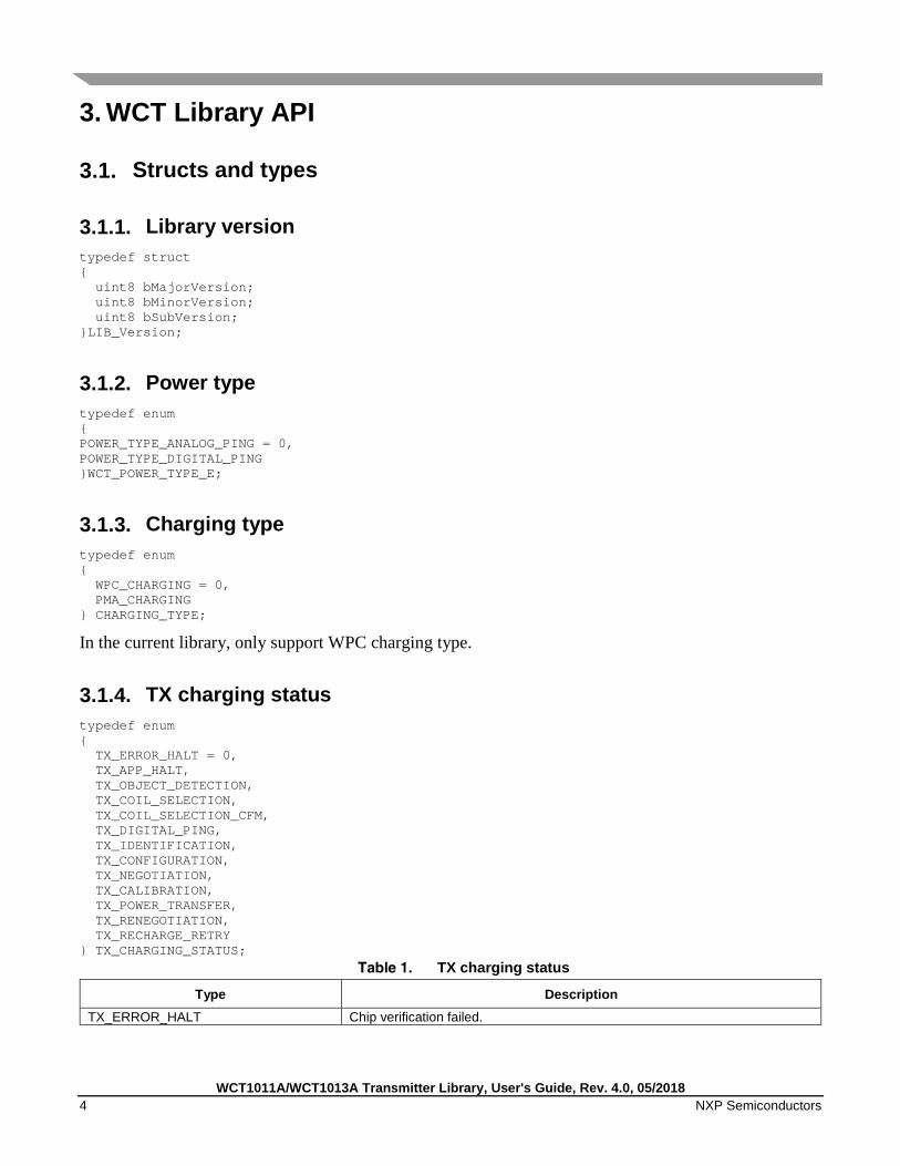
3.1.4. TX charging status typedef enum { TX_ERROR_HALT = 0, TX_APP_HALT, TX_OBJECT_DETECTION, TX_COIL_SELECTION, TX_COIL_SELECTION_CFM, TX_DIGITAL_PING, TX_IDENTIFICATION, TX_CONFIGURATION, TX_NEGOTIATION, TX_CALIBRATION, TX_POWER_TRANSFER, TX_RENEGOTIATION, TX_RECHARGE_RETRY } TX_CHARGING_STATUS;
TX charging status
Type Description TX_ERROR_HALT Chip verification failed.

WCT1011A/WCT1013A Transmitter Library, User's Guide, Rev. 4.0, 05/2018 NXP Semiconductors 5
TX_APP_HALT Application stopped TX by calling WCT_Stop(). TX_OBJECT_DETECTION TX is detecting existence of the RX. TX_COIL_SELECTION TX is selecting the best coil. TX_COIL_SELECTION_CFM TX is confirming the best coil. TX_DIGITAL_PING TX has found the best coil. Do digital ping as in specification. TX_IDENTIFICATION TX is in identification state as in specification. TX_CONFIGURATION TX is in configuration state as in specification. TX_NEGOTIATION TX is in negotiation state as in specification. TX_CALIBRATION TX is in calibration state as in specification. TX_POWER_TRANSFER TX is in power transfer state as in specification. TX_RENEGOTIATION TX is in re-negotiation state as in specification. TX_RECHARGE_RETRY TX waits some time to restart if an error occurs, unless RX is removed.
3.1.5. TX charging error typedef enum { TX_SUCCESS = 0, TX_CHIP_ERROR, TX_FOD_ERROR, TX_QFOD_ERROR, TX_RUNTIME_PARAM_ERROR, TX_CHARGE_REPEATED_FAIL } TX_CHARGING_ERRORS;
TX charging error
Type Description TX_SUCCESS No error occurs. TX_CHIP_ERROR Chip verification failed. TX_FOD_ERROR FOD by power loss method. TX_QFOD_ERROR FOD by quality factor method. TX_RUNTIME_PARAM_ERROR Runtime parameter error, such as current and voltage from the application. TX_CHARGE_REPEATED_FAIL Repeated failure when charging an RX.
3.1.6. RX charging status typedef enum
{
RX_NONE = 0,
RX_PREPARE_CHARGE,
RX_CHARGING,
RX_CHARGED,
RX_UNDEFINE,
RX_FAULT
} RX_CHARGING_STATUS;
RX charging status
Type Description RX_NONE RX is not detected yet, such as from start or reset. RX_PREPARE_CHARGE Can be seen as RX detected and provides user indication, during coil selection.
WCT1011A/WCT1013A Transmitter Library, User's Guide, Rev. 4.0, 05/2018 6 NXP Semiconductors
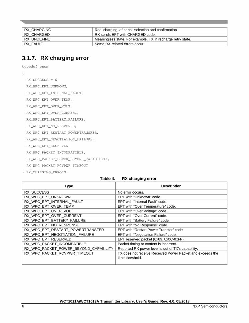
RX_CHARGING Real charging, after coil selection and confirmation. RX_CHARGED RX sends EPT with CHARGED code. RX_UNDEFINE Meaningless state. For example, TX in recharge retry state. RX_FAULT Some RX-related errors occur.
3.1.7. RX charging error typedef enum
{
RX_SUCCESS = 0,
RX_WPC_EPT_UNKNOWN,
RX_WPC_EPT_INTERNAL_FAULT,
RX_WPC_EPT_OVER_TEMP,
RX_WPC_EPT_OVER_VOLT,
RX_WPC_EPT_OVER_CURRENT,
RX_WPC_EPT_BATTERY_FAILURE,
RX_WPC_EPT_NO_RESPONSE,
RX_WPC_EPT_RESTART_POWERTRANSFER,
RX_WPC_EPT_NEGOTIATION_FAILURE,
RX_WPC_EPT_RESERVED,
RX_WPC_PACKET_INCOMPATIBLE,
RX_WPC_PACKET_POWER_BEYOND_CAPABILITY,
RX_WPC_PACKET_RCVPWR_TIMEOUT
} RX_CHARGING_ERRORS;
RX charging error
Type Description RX_SUCCESS No error occurs. RX_WPC_EPT_UNKNOWN EPT with “Unknown” code. RX_WPC_EPT_INTERNAL_FAULT EPT with “Internal Fault” code. RX_WPC_EPT_OVER_TEMP EPT with “Over Temperature” code. RX_WPC_EPT_OVER_VOLT EPT with “Over Voltage” code. RX_WPC_EPT_OVER_CURRENT EPT with “Over Current” code. RX_WPC_EPT_BATTERY_FAILURE EPT with “Battery Failure” code. RX_WPC_EPT_NO_RESPONSE EPT with “No Response” code. RX_WPC_EPT_RESTART_POWERTRANSFER EPT with “Restart Power Transfer” code. RX_WPC_EPT_NEGOTIATION_FAILURE EPT with “Negotiation Failure” code. RX_WPC_EPT_RESERVED EPT reserved packet (0x09, 0x0C-0xFF). RX_WPC_PACKET_INCOMPATIBLE Packet timing or content is incorrect. RX_WPC_PACKET_POWER_BEYOND_CAPABILITY Reported RX power level is out of TX's capability. RX_WPC_PACKET_RCVPWR_TIMEOUT TX does not receive Received Power Packet and exceeds the
time threshold.

WCT1011A/WCT1013A Transmitter Library, User's Guide, Rev. 4.0, 05/2018 NXP Semiconductors 7
3.1.8. Recharge error type typedef enum
{
RECHARGETIME_RX_UNKNOWN = 0,
RECHARGETIME_RX_CHARGE_COMPLETE,
RECHARGETIME_RX_INTERNAL_FAULT,
RECHARGETIME_RX_OVER_TEMP,
RECHARGETIME_RX_OVER_VOLT,
RECHARGETIME_RX_OVER_CURRENT,
RECHARGETIME_RX_BATTERY_FAILURE,
RECHARGETIME_RX_NO_RESPONSE,
RECHARGETIME_RX_RESTART_POWERXFER,
RECHARGETIME_RX_NEGOTIATION_FAILURE,
RECHARGETIME_RX_POWER_BEYOND_CAPABILITY,
RECHARGETIME_TX_RCVPWR_TIMEOUT,
RECHARGETIME_TX_FOD_ERROR,
RECHARGETIME_TX_QFOD_ERROR,
RECHARGETIME_TX_CHARGE_REPEATED_FAIL
}E_RECHARGETIME_SETTYPE;
Recharge error type
Type Description RECHARGETIME_RX_UNKNOWN RX unknown error RECHARGETIME_RX_CHARGE_COMPLETE RX gets charged RECHARGETIME_RX_INTERNAL_FAULT RX internal fault RECHARGETIME_RX_OVER_TEMP RX over temperature RECHARGETIME_RX_OVER_VOLT RX over voltage RECHARGETIME_RX_OVER_CURRENT RX over current RECHARGETIME_RX_BATTERY_FAILURE RX battery fault RECHARGETIME_RX_NO_RESPONSE RX considers TX no response RECHARGETIME_RX_RESTART_POWERXFER RX requires restart power transfer RECHARGETIME_RX_NEGOTIATION_FAILURE RX negotiation failed RECHARGETIME_RX_POWER_BEYOND_CAPABILITY RX requires more power than TX could afford RECHARGETIME_TX_RCVPWR_TIMEOUT TX can not get received power packet in
time(normally 23s) RECHARGETIME_TX_FOD_ERROR TX enter FOD status RECHARGETIME_TX_QFOD_ERROR TX can not pass Q factor check when charging EPP
RX RECHARGETIME_TX_CHARGE_REPEATED_FAIL TX fails to charge RX
WCT1011A/WCT1013A Transmitter Library, User's Guide, Rev. 4.0, 05/2018 8 NXP Semiconductors
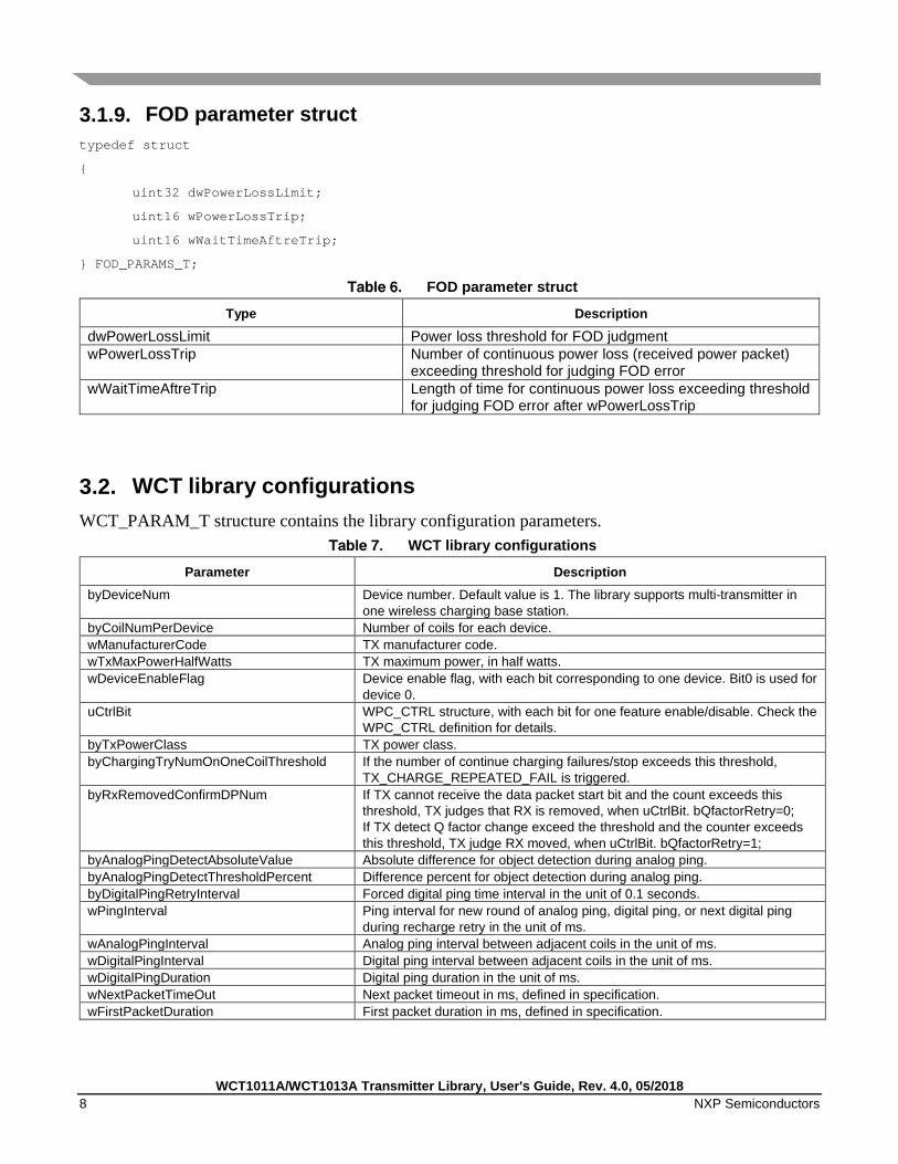
3.1.9. FOD parameter struct typedef struct
{
uint32 dwPowerLossLimit;
uint16 wPowerLossTrip;
uint16 wWaitTimeAftreTrip;
} FOD_PARAMS_T;
FOD parameter struct
Type Description
dwPowerLossLimit Power loss threshold for FOD judgment wPowerLossTrip Number of continuous power loss (received power packet)
exceeding threshold for judging FOD error wWaitTimeAftreTrip Length of time for continuous power loss exceeding threshold
for judging FOD error after wPowerLossTrip
3.2. WCT library configurations WCT_PARAM_T structure contains the library configuration parameters.
WCT library configurations
Parameter Description byDeviceNum Device number. Default value is 1. The library supports multi-transmitter in
one wireless charging base station. byCoilNumPerDevice Number of coils for each device. wManufacturerCode TX manufacturer code. wTxMaxPowerHalfWatts TX maximum power, in half watts. wDeviceEnableFlag Device enable flag, with each bit corresponding to one device. Bit0 is used for
device 0. uCtrlBit WPC_CTRL structure, with each bit for one feature enable/disable. Check the
WPC_CTRL definition for details. byTxPowerClass TX power class. byChargingTryNumOnOneCoilThreshold If the number of continue charging failures/stop exceeds this threshold,
TX_CHARGE_REPEATED_FAIL is triggered. byRxRemovedConfirmDPNum If TX cannot receive the data packet start bit and the count exceeds this
threshold, TX judges that RX is removed, when uCtrlBit. bQfactorRetry=0; If TX detect Q factor change exceed the threshold and the counter exceeds this threshold, TX judge RX moved, when uCtrlBit. bQfactorRetry=1;
byAnalogPingDetectAbsoluteValue Absolute difference for object detection during analog ping. byAnalogPingDetectThresholdPercent Difference percent for object detection during analog ping. byDigitalPingRetryInterval Forced digital ping time interval in the unit of 0.1 seconds. wPingInterval Ping interval for new round of analog ping, digital ping, or next digital ping
during recharge retry in the unit of ms. wAnalogPingInterval Analog ping interval between adjacent coils in the unit of ms. wDigitalPingInterval Digital ping interval between adjacent coils in the unit of ms. wDigitalPingDuration Digital ping duration in the unit of ms. wNextPacketTimeOut Next packet timeout in ms, defined in specification. wFirstPacketDuration First packet duration in ms, defined in specification.

WCT1011A/WCT1013A Transmitter Library, User's Guide, Rev. 4.0, 05/2018 NXP Semiconductors 9
Parameter Description wMaxPacketDuration Maximum packet duration in ms, defined in specification. wRPPTimeOut Received Power Packet timeout in ms, defined in specification. wCEPTimeOut Control Error Packet timeout in ms, defined in specification. wMsgHeaderTimeOut Data packet start bit timeout in ms. wTimeForWaitNextNegotiationPacket Next packet timeout in ms during the negotiation phase. wQPrepareInterval Interval between Q factor measurement and last digital ping in coil selection. wQMeasureInterval Interval between the Q factor measurement operations. wRailSetupTime Vrail voltage setup time of DCDC. wAnalogPingPowerSetupTime Vrail voltage setup time of analog ping power source. wRailDischargeTime Vrail discharge time. wDDMStartDelayTimeAfterCharging Interval between DDM start and charging/inverter start. wDDMRetryTimeout Threshold for DDM does not receive a packet. If the threshold is exceeded,
DDM switches its ADC trigger position. wSendFSKDelay Interval between FSK responds and last packet received from RX. wCalibrationTimeout Timeout out for calibration phase duration. wDefaultRailVoltageMv An array containing the default rail voltage for each coil. wDigitalPingDuty Duty cycle for digital ping. wDigitalPingPhase Phase for digital ping. wMaxDuty Maximum duty cycle. wMinDuty Minimum duty cycle. wMaxPhase Maximum phase. wMinPhase Minimum phase. wMaxRailVoltageMv Maximum rail voltage in the unit of mv. wMinRailVoltageMv Minimum rail voltage in the unit of mv. dwDigitalPingFreq Digital ping frequency. dwMaxFreq Maximum frequency. dwMinFreq Minimum frequency. dwFobAvoidFreqency Frequency to be jumped to when keyfob is enabled. byDigitalPinglBridgeType Inverter bridge type for digital ping. byNumFodTripsToIndication Number of times FOD exceeding threshold occurs after the RPP packet is
received. This starts the accumulation of the FOD confirmation time. wLPPowerLossThresholdInOperationMode Power loss threshold for LP Rx. Application could assign a specific value for
a receiver, regardless of what this value is. wMPPowerLossThresholdInOperationMode Power loss threshold for MP Rx. Application could assign a specific value for
a receiver, regardless of what this value is wPowerLossThresholdInCalibLightMode Power loss threshold for calibration light mode. If the threshold is exceeded,
TX sends a NAK response to the 24-bit power packet of light mode in calibration phase from RX.
wPowerLossThresholdInCalibConnectMode Power loss threshold for calibration connect mode. If the threshold is exceeded, TX sends a NAK response to the 24-bit power packet of light mode in calibration phase from RX.
wPowerLossIndicationToPwrCessationMs If the FOD confirmation time exceeds this threshold, FOD error TX_FOD_ERROR occurs.
wPowerLossThresholdForLegacyRx Power loss threshold for those receivers whose version is earlier than V1.1. byDefaultWindowSize Default window size if the window size is not set correctly in the configuration
packet from RX. byQfactorThresholdPercent Threshold for the Q reported from RX. byQfactorAdjsutPercent Adjust value of the measured Q factor of TX. byEffiThresholdPercentForLegacyRx Efficiency threshold for those receivers whose version is earlier than V1.1.
If both byEffiThresholdPercentForLegacyRx and PowerLossThresholdForLegacyRx are satisfied, TX considers there is FO.
pFodExternalCheck Function pointer to customer FOD detection method.
WCT1011A/WCT1013A Transmitter Library, User's Guide, Rev. 4.0, 05/2018 10 NXP Semiconductors
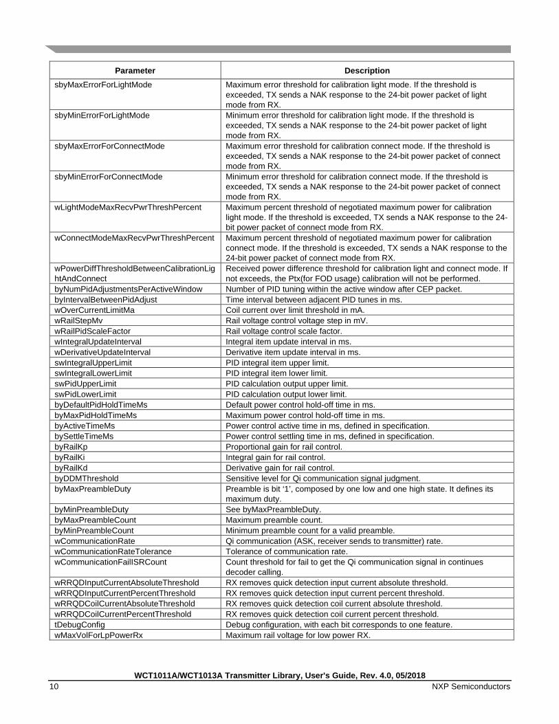
Parameter Description sbyMaxErrorForLightMode Maximum error threshold for calibration light mode. If the threshold is
exceeded, TX sends a NAK response to the 24-bit power packet of light mode from RX.
sbyMinErrorForLightMode Minimum error threshold for calibration light mode. If the threshold is exceeded, TX sends a NAK response to the 24-bit power packet of light mode from RX.
sbyMaxErrorForConnectMode Maximum error threshold for calibration connect mode. If the threshold is exceeded, TX sends a NAK response to the 24-bit power packet of connect mode from RX.
sbyMinErrorForConnectMode Minimum error threshold for calibration connect mode. If the threshold is exceeded, TX sends a NAK response to the 24-bit power packet of connect mode from RX.
wLightModeMaxRecvPwrThreshPercent Maximum percent threshold of negotiated maximum power for calibration light mode. If the threshold is exceeded, TX sends a NAK response to the 24-bit power packet of connect mode from RX.
wConnectModeMaxRecvPwrThreshPercent Maximum percent threshold of negotiated maximum power for calibration connect mode. If the threshold is exceeded, TX sends a NAK response to the 24-bit power packet of connect mode from RX.
wPowerDiffThresholdBetweenCalibrationLightAndConnect
Received power difference threshold for calibration light and connect mode. If not exceeds, the Ptx(for FOD usage) calibration will not be performed.
byNumPidAdjustmentsPerActiveWindow Number of PID tuning within the active window after CEP packet. byIntervalBetweenPidAdjust Time interval between adjacent PID tunes in ms. wOverCurrentLimitMa Coil current over limit threshold in mA. wRailStepMv Rail voltage control voltage step in mV. wRailPidScaleFactor Rail voltage control scale factor. wIntegralUpdateInterval Integral item update interval in ms. wDerivativeUpdateInterval Derivative item update interval in ms. swIntegralUpperLimit PID integral item upper limit. swIntegralLowerLimit PID integral item lower limit. swPidUpperLimit PID calculation output upper limit. swPidLowerLimit PID calculation output lower limit. byDefaultPidHoldTimeMs Default power control hold-off time in ms. byMaxPidHoldTimeMs Maximum power control hold-off time in ms. byActiveTimeMs Power control active time in ms, defined in specification. bySettleTimeMs Power control settling time in ms, defined in specification. byRailKp Proportional gain for rail control. byRailKi Integral gain for rail control. byRailKd Derivative gain for rail control. byDDMThreshold Sensitive level for Qi communication signal judgment. byMaxPreambleDuty Preamble is bit ‘1’, composed by one low and one high state. It defines its
maximum duty. byMinPreambleDuty See byMaxPreambleDuty. byMaxPreambleCount Maximum preamble count. byMinPreambleCount Minimum preamble count for a valid preamble. wCommunicationRate Qi communication (ASK, receiver sends to transmitter) rate. wCommunicationRateTolerance Tolerance of communication rate. wCommunicationFailISRCount Count threshold for fail to get the Qi communication signal in continues
decoder calling. wRRQDInputCurrentAbsoluteThreshold RX removes quick detection input current absolute threshold. wRRQDInputCurrentPercentThreshold RX removes quick detection input current percent threshold. wRRQDCoilCurrentAbsoluteThreshold RX removes quick detection coil current absolute threshold. wRRQDCoilCurrentPercentThreshold RX removes quick detection coil current percent threshold. tDebugConfig Debug configuration, with each bit corresponds to one feature. wMaxVolForLpPowerRx Maximum rail voltage for low power RX.

WCT1011A/WCT1013A Transmitter Library, User's Guide, Rev. 4.0, 05/2018 NXP Semiconductors 11
Parameter Description wMaxVolForMpPowerRx Maximum rail voltage for medium power RX. wLowLoadingThreshold Transmitted power (loading) threshold to trigger the wMaxVolForLowLoading. wMaxVolForLowLoading Maximum rail voltage for low loading threshold. wHeavyLoadingThreshold Transmitted power (loading) threshold to trigger
wMinPowerFactorForHeavyLoading. wMinPowerFactorForHeavyLoading Power factor threshold in heavy loading defined by
wHeavyLoadingThreshold. If the threshold is not exceeded, TX does not reply positive CEP.
wMaxDigitalPingTimeRefCounts Reference count threshold for digital ping. wFirstPacketTimeoutRefCounts Reference count threshold for the first packet. wNextPacketTimeoutRefCounts Reference count threshold for interval between previous and next packets. dwCommReferenceTimerFreq Reference counter frequency. dwCommReferenceTimerMaxCount Maximum count value of the reference counter. dwSafeDigitalPingFreq Frequency for safe digital ping. wSafeDigitalPingCheckTime Duration for safe digital ping. wSafeDigitalPingDuty Duty cycle for safe digital ping. wSafeDigitalPingPhase Phase for safe digital ping. bySafeDigitalPinglBridgeType Inverter bridge type for safe digital ping. wQfactorChangeThreshold When recharge retry, TX consider RX moved when Q factor value change
exceeds this threshold and the counter exceeds byRxRemovedConfirmDPNum, TX consider RX get moved when uCtrlBit. bQfactorRetry=1
wMPLRPPThreshold Received power exceeds this threshold triggers Maximum power limit feature wMPLHysteresis Hysteresis of wMPLRPPThreshold for TX exit MPL status byQfStableThreshold TX consider the measured Q factor is stable when current and previous Q
factor change is within this threshold, in unit of percentage. byQfMeasureNum Maximum Q factor measurement times for getting a stable Q factor byQfAveNumForRetry
Average number for Q factor measurement during recharge retry.
byMinTxMeasuredQfToStopRetry
When TX measured Q factor is greater than this value, TX consider there is no object on TX surface, and exit recharge retry.
byMaxRxReportedQFactor Rx reported Q factor limiter.
byFCIncPercentForLowSS
When signal strength is less than byFCSSThreshold, Tx will increase power by byFCIncPercentForLowSS after configuration packet. This feature could be disabled by set byFCSSThreshold = 0.
byFCSSThreshold
Signal strength threshold for fast charging.
byAPPRollBackWin
TX inverter input power window which rolls back, to compare with current input power. In unit of 4ms.
wAPPDumpPowerAbsoluteThreshold Absolute dump power threshold to trigger active power protection. In unit of mW.
byAPPVolDumpScale
Voltage (Vrail) dump scale (by percent) when APP is triggered.
byAPPDumpPowerPercentageThreshold
Relative dump power threshold to trigger active power protection.

WCT1011A/WCT1013A Transmitter Library, User's Guide, Rev. 4.0, 05/2018 12 NXP Semiconductors
3.3. WCT library API functions
3.3.1. WCT_GetLibVer Prototype:
void WCT_GetLibVer(LIB_Version *pLibVersion);
Description: Gets the WCT library version.
Parameters: pLibVersion: the data pointer for version structure
Return: The version number is returned in the version structure pointer pLibVersion.
3.3.2. WCT_Init Prototype:
void WCT_Init( void );
Description: WCT library initialization. It initializes and resets the WCT internal states.
3.3.3. WCT_Run Prototype:
uint16 WCT_Run( uint16 wTimePassedMs );
Description: Main entry function of the WCT library. Make sure that this function is called within 1 ms interval to ensure timing requirements of Qi certification.
Parameters: wTimePassedMs: Time elapsed since last call of this function
Return: The time length for next WCT activity. It is used by the application to judge how long to enter low-power mode.
3.3.4. WCT_Stop Prototype:
void WCT_Stop(void);

WCT1011A/WCT1013A Transmitter Library, User's Guide, Rev. 4.0, 05/2018 NXP Semiconductors 13
Description: Stops the WCT state machine from the application. If the WCT state machine needs to be started again, call WCT_Init(). See the demo application.
3.3.5. WCT_CommAnalyse Prototype:
void WCT_CommAnalyse(uint8 byDeviceId);
Description: Library callback function of DMA interrupt for DDM only. In current implementation, when 128 samples of coil current are collected, this function is called.
Parameters: byDevice: device ID
3.3.6. WCT_ChargeSpecificCoil Prototype:
void WCT_ChargeSpecificCoil(uint8 byDeviceId, uint8 byCoilId, CHARGING_TYPE ChargeType);
Description: Application can select one coil and start charging directly without coil selection.
Parameters: byDeviceId: device ID
byCoilId: coil ID
ChargeType: the type of charging; only supports WPC now
3.3.7. WCT_GetChargingType Prototype:
CHARGING_TYPE WCT_GetChargingType(uint8 byDeviceId);
Description: Gets the current charging type.
Parameters: byDeviceId: device ID
Return: The current charging type.
WCT1011A/WCT1013A Transmitter Library, User's Guide, Rev. 4.0, 05/2018 14 NXP Semiconductors
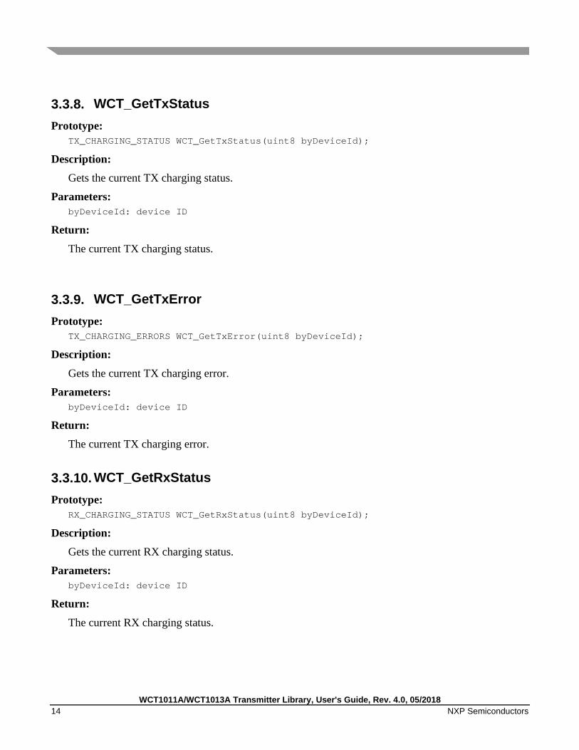
3.3.8. WCT_GetTxStatus Prototype:
TX_CHARGING_STATUS WCT_GetTxStatus(uint8 byDeviceId);
Description: Gets the current TX charging status.
Parameters: byDeviceId: device ID
Return:
The current TX charging status.
3.3.9. WCT_GetTxError Prototype:
TX_CHARGING_ERRORS WCT_GetTxError(uint8 byDeviceId);
Description:
Gets the current TX charging error.
Parameters: byDeviceId: device ID
Return: The current TX charging error.
3.3.10. WCT_GetRxStatus Prototype:
RX_CHARGING_STATUS WCT_GetRxStatus(uint8 byDeviceId);
Description: Gets the current RX charging status.
Parameters: byDeviceId: device ID
Return:
The current RX charging status.
WCT1011A/WCT1013A Transmitter Library, User's Guide, Rev. 4.0, 05/2018 NXP Semiconductors 15
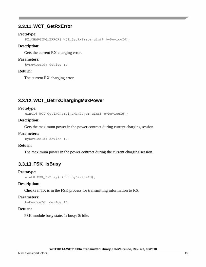
3.3.11. WCT_GetRxError Prototype:
RX_CHARGING_ERRORS WCT_GetRxError(uint8 byDeviceId);
Description: Gets the current RX charging error.
Parameters: byDeviceId: device ID
Return:
The current RX charging error.
3.3.12. WCT_GetTxChargingMaxPower Prototype:
uint16 WCT_GetTxChargingMaxPower(uint8 byDeviceId);
Description:
Gets the maximum power in the power contract during current charging session.
Parameters: byDeviceId: device ID
Return: The maximum power in the power contract during the current charging session.
3.3.13. FSK_IsBusy Prototype:
uint8 FSK_IsBusy(uint8 byDeviceId);
Description: Checks if TX is in the FSK process for transmitting information to RX.
Parameters: byDeviceId: device ID
Return:
FSK module busy state. 1: busy; 0: idle.

WCT1011A/WCT1013A Transmitter Library, User's Guide, Rev. 4.0, 05/2018 16 NXP Semiconductors
3.3.14. FSK_ISR Prototype:
void FSK_ISR(uint8 byDeviceId);
Description: The function to implement FSK process for transmitting information to RX. This function is called from hardware counter interrupt.
Parameters: byDeviceId: device ID
4. WCT Interface API
4.1. Middleware interface
4.1.1. WCT_OnWPCPacketRecv Prototype:
void WCT_OnWPCPacketRecv(uint8 byDeviceId, uint8 bySize, uint8 *pbyData)
Description:
This is a callback function, called when a data packet is received from RX.
Parameters: byDeviceId: device ID
bySize: data packet size
pbyData: data packet pointer
Return: None
4.1.2. WCT_SetReChargeTimeOnAbnormal Prototype:
uint32 WCT_SetReChargeTimeOnAbnormal(E_RECHARGETIME_SETTYPE eAbnormalType)
Description: This is a callback function for application to configure the wait time for recharge retry.
Parameters: eAbnormalType: check E_RECHARGETIME_SETTYPE in header file, which contains both TX error and RX errors.

WCT1011A/WCT1013A Transmitter Library, User's Guide, Rev. 4.0, 05/2018 NXP Semiconductors 17
Return: Wait time for recharge retry.
4.1.3. WCT_GetFODParams Prototype:
FOD_PARAMS_T* WCT_GetFODParams(PACKET_RX_INFO_T *pRxInfo, POWER_CONTRACT *pPowerContractInfo)
Description: This is a callback function to set special FOD parameters for dedicated RXs. Basically the RX manufacture ID is used for identifying the RXs.
Parameters: pRxInfo: RX-related information sent from RX data packets. See PACKET_RX_INFO_T definition in header file. pPowerContractInfo: Power contract related information. See POWER_CONTRACT definition in header file.
Return: FOD parameters for dedicated RX. See FOD_PARAMS_T definition in header file.
4.1.4. WCT_UpdateDevUsrIndication Prototype:
void WCT_UpdateDevUsrIndication(uint8 byDeviceId)
Description: This is a callback function to set TX user indication, like LED, when certain TX or RX events occur.
Parameters: byDeviceId: Device ID
Return:
None
4.1.5. DBG_Assert Prototype:
void DBG_Assert(uint8 byAssert, uint32 dwAssertCode, uint32 dwParameter)
Description:
This is a debug function to identify serious bugs in library. Parameters:
byAssert: Assert flag
WCT1011A/WCT1013A Transmitter Library, User's Guide, Rev. 4.0, 05/2018 18 NXP Semiconductors
dwAssertCode: Assert code, which helps to identify which part in library gets problem dwParameter: Assert parameter, which is useful for debug
Return: None
4.1.6. DBG_Warning Prototype:
void DBG_Warning(uint8 byWarning, uint32 dwWarningCode, uint32 dwParameter)
Description: This is a warning function to identify abnormal code routine in library.
Parameters: byWarning: Warning flag dwWarningCode: Warning code, which helps to identify which part of library gets warning dwParameter: Warning parameter, which is useful for debug
Return: None
4.1.7. SPRT_PrintChar Prototype:
void SPRT_PrintChar(uint8 byChar)
Description: This is a print function to print a char.
Parameters: byChar: print character
Return: None
4.1.8. SPRT_PrintString Prototype:
void SPRT_PrintString(uint8 *pbyStr)
Description: This is a print function to print a string.
Parameters: pbyStr: Pointer of print string

WCT1011A/WCT1013A Transmitter Library, User's Guide, Rev. 4.0, 05/2018 NXP Semiconductors 19
Return: None
4.1.9. SPRT_PrintDecChar Prototype:
void SPRT_PrintDecChar(uint8 byChar)
Description: This is a print function to print a character in decimal format.
Parameters: byChar: Decimal value
Return: None
4.1.10. SPRT_PrintHexChar Prototype:
void SPRT_PrintHexChar(uint8 byChar)
Description: This is a print function to print a character in hex format.
Parameters: byChar: hex value
Return: None
4.1.11. SPRT_PrintSignedDecChar Prototype:
void SPRT_PrintSignedDecChar(uint8 byChar)
Description: This is a print function to print a character in signed decimal format.
Parameters: byChar: signed decimal value
Return: None

WCT1011A/WCT1013A Transmitter Library, User's Guide, Rev. 4.0, 05/2018 20 NXP Semiconductors
4.1.12. SPRT_PrintSignedDecWord Prototype:
void SPRT_PrintSignedDecWord(uint16 wValue)
Description: This is a print function to print a word variable in signed decimal format.
Parameters: wValue: variable in word
Return: None
4.1.13. SPRT_PrintDoubleWordValue Prototype:
void SPRT_PrintDoubleWordValue(uint32 dwValue)
Description: This is a print function to print a double word variable in decimal format.
Parameters: dwValue: variable in double word
Return: None
4.1.14. PROT_CheckRunTimeParams Prototype:
boolean PROT_CheckRunTimeParams(uint8 byDeviceId, uint8 byCoilId, TX_CHARGING_STATUS eState, uint16 wGuaranteedPower, uint16 wTimePassedMs)
Description: This is a function to check runtimes parameter, say input current, rail voltage, coil current, and input power.
Parameters: byDeviceId: Device ID byCoilId: Coil ID eState: Charging state wGuaranteedPower: Maximum negotiated guaranteed power. This value is valid only when eState = TX_CALIBRATION, TX_POWER_TRANSFER or TX_RENEGOTIATION. wTimePassedMs: Time elapsed since last call of this function.
Return:

WCT1011A/WCT1013A Transmitter Library, User's Guide, Rev. 4.0, 05/2018 NXP Semiconductors 21
Abnormal status. 0: normal; 1: abnormal
4.1.15. PROT_SafeDigitalPingParamCheck Prototype:
boolean PROT_SafeDigitalPingParamCheck(uint8 byDeviceId)
Description: This function is called after digital ping starts for gWCT_Params.wSafeDigitalPingCheckTime.
Parameters: byDeviceId: Device ID
Return: Abnormal status. 0: normal; 1: abnormal
4.1.16. PROT_GetRRQDFittingInputCurrent Prototype:
uint16 PROT_GetRRQDFittingInputCurrent(uint8 byDeviceId, uint8 byCoilId, uint16 wRailVoltage, uint32 dwFreq)
Description: This function returns the input current at wRailVoltage for byCoilId when it works without any object on it.
Parameters: byDeviceId: device id byCoilId: coil id wRailVoltage: rail voltage in mV dwFreq: working frequency
Return: Input current in mA
4.1.17. PROT_GetRRQDFittingCoilCurrent Prototype:
uint16 PROT_GetRRQDFittingCoilCurrent(uint8 byDeviceId, uint8 byCoilId, uint16 wRailVoltage, uint32 dwFreq)
Description: This function returns the coil current at wRailVoltage for byCoilId when it works without any object on it.
Parameters: byDeviceId: Device ID byCoilId: Coil ID
WCT1011A/WCT1013A Transmitter Library, User's Guide, Rev. 4.0, 05/2018 22 NXP Semiconductors
wRailVoltage: Rail voltage in mV dwFreq: working frequency
Return: Coil current in mA
4.1.18. ST_GetTimerTick Prototype:
uint16 ST_GetTimerTick(void)
Description: Returns the tick time in ms.
Parameters: None
Return: Tick time in ms.
4.1.19. ST_GetElapasedTime Prototype:
uint16 ST_GetElapasedTime(uint16 wLastTick)
Description: Returns the elapsed time since wLastTick.
Parameters: wLastTick: previous time mark for tick timer
Return: Elapsed time since wLastTick in ms.
4.1.20. ST_WaitMs Prototype:
void ST_WaitMs(uint16 wNumMs)
Description: Wait wNumMs ms in block mode.
Parameters: wNumMs: wait time in ms
Return: None

WCT1011A/WCT1013A Transmitter Library, User's Guide, Rev. 4.0, 05/2018 NXP Semiconductors 23
4.1.21. QF_QMeasurePrepare Prototype:
QF_MEASURE_RESULT_E QF_QMeasurePrepare(uint8 byDeviceId, uint8 byCoilId)
Description: Preparation before Q factor measurement.
Parameters: byDeviceId: Device ID byCoilId: Coil ID
Return: Execution result of preparation. See QF_MEASURE_RESULT_E
4.1.22. QF_QMeasure Prototype:
QF_MEASURE_RESULT_E QF_QMeasure(uint8 byDeviceId, uint8 byCoilId)
Description: Perform measurement for Q factor of LC resonance tank.
Parameters: byDeviceId: Device ID byCoilId: Coil ID
Return: Execution result of measurement. See QF_MEASURE_RESULT_E
4.1.23. QF_GetQFactor Prototype:
QF_MEASURE_RESULT_E QF_GetQFactor(uint8 byDeviceId, uint8 byCoilId, uint32 *pFreq, uint32* plcQ)
Description: Gets the measured Q factor of LC resonance tank.
Parameters: byDeviceId: Device ID byCoilId: Coil ID pFreq: Pointer for saving the resonance frequency plcQ: Pointer for saving the Q factor of LC resonance tank
Return: Execution result. See QF_MEASURE_RESULT_E
WCT1011A/WCT1013A Transmitter Library, User's Guide, Rev. 4.0, 05/2018 24 NXP Semiconductors
4.2. HAL interface
4.2.1. HAL_DisableIRQ Prototype:
uint8 HAL_DisableIRQ(void);
Description: Disables the global IRQ.
Parameters: None
Return: The global IRQ status before the global IRQ is disabled.
4.2.2. HAL_RestoreIRQ Prototype:
void HAL_RestoreIRQ(uint8 bySts);
Description: Restores the global IRQ.
Parameters: bySts : The global IRQ status. 0: disable; 1: enable.
Return: None
4.2.3. HAL_GetRailVoltage Prototype:
uint16 HAL_GetRailVoltage(uint8 byDeviceId);
Description: Gets the rail voltage, and it should be an average value of 4 ms window.
Parameters: byDeviceId : Device ID
Return: The rail voltage in mV.

WCT1011A/WCT1013A Transmitter Library, User's Guide, Rev. 4.0, 05/2018 NXP Semiconductors 25
4.2.4. HAL_GetBatteryVoltage Prototype:
uint16 HAL_GetBatteryVoltage(void);
Description: Gets the input voltage of board.
Parameters: None
Return: The board input voltage in mV.
4.2.5. HAL_GetCoilCurrent Prototype:
uint16 HAL_GetCoilCurrent(uint8 byDeviceId, uint8 byCoilId);
Description: Gets the coil current of coil.
Parameters: byDeviceId: Device id byCoilId: Coil id
Return: The coil current(RMS) in mA.
4.2.6. HAL_GetInputCurrent Prototype:
uint16 HAL_GetInputCurrent(uint8 byDeviceId);
Description: Gets the input current of inverter.
Parameters: byDeviceId: device id
Return: The input current in mA.

WCT1011A/WCT1013A Transmitter Library, User's Guide, Rev. 4.0, 05/2018 26 NXP Semiconductors
4.2.7. HAL_EnableDDM Prototype:
void HAL_EnableDDM(uint8 byDeviceId, uint8 byCoilId, uint8 byIsEn);
Description: Enable or disable DDM operation in hardware level.
Parameters: byDeviceId: Device ID byCoilId: Coil ID byIsEn: 0: disable; 1: enable.
Return: None
4.2.8. HAL_AnalogPing Prototype:
uint16 HAL_AnalogPing(uint8 byDeviceId, uint8 byCoilId);
Description: Does analog ping and returns the result of analog ping.
Parameters: byDeviceId: Device ID byCoilId: Coil ID
Return: The result of analog ping (typically represents analog variable in real word).
4.2.9. HAL_FindAdcTriggerPos Prototype:
uint16 HAL_FindAdcTriggerPos(uint8 byDeviceId, uint8 byCoilId, uint8 byDiv, uint32 dwFreq, uint32 dwDuty, uint32 dwPhase);
Description: Searches the valley position of the DDM signal (scaled down from resonance signal) and sets the DDM trigger position, depending on byDiv. Meanwhile it also calculates the coil current according to the DDM signal valley value, and the power factor of inverter.
Parameters: byDeviceId: Device ID byCoilId: Coil ID
byDiv: DDM trigger position setting. 0, 1: the valley position; 2: right to valley position; 3: left to valley position.

WCT1011A/WCT1013A Transmitter Library, User's Guide, Rev. 4.0, 05/2018 NXP Semiconductors 27
dwFreq: Working frequency of resonance tank dwDuty: Working duty of resonance tank dwPhase: Working phase (if full bridge topology) of resonance tank
Return: The power factor of inverter.
4.2.10. HAL_SetChargingBridge Prototype:
void HAL_SetChargingBridge(uint8 byDeviceId, uint8 byCoilId, uint8 byBridge);
Description: Sets the topology of inverter which drives the resonance tank.
Parameters: byDeviceId: Device ID byCoilId: Coil ID byBridge: Topology type. 0: half bridge; 1: full bridge
Return: None
4.2.11. HAL_EnableCoilDischarge Prototype:
void HAL_EnableCoilDischarge(uint8 byDeviceId, uint8 byCoilId, boolean bIsEn);
Description: Discharges the resonance tank circuit (normally called when inverter/resonance tank is not working).
Parameters: byDeviceId: Device ID byCoilId: Coil ID bIsEn: 0: not discharge; 1: discharge
Return: None
4.2.12. HAL_EnableChargingOnCoil Prototype:
void HAL_EnableChargingOnCoil(uint8 byDeviceId, uint8 byCoilId, boolean bIsEn);
Description: Start/Stop to work (charging) on specific coil (inverter).

WCT1011A/WCT1013A Transmitter Library, User's Guide, Rev. 4.0, 05/2018 28 NXP Semiconductors
Parameters: byDeviceId: Device ID
byCoilId: Coil ID bIsEn: 0: stop charging; 1: start charging
Return: None
4.2.13. HAL_SetChargingFreqDutyPhase Prototype:
void HAL_SetChargingFreqDutyPhase(uint8 byDeviceId, uint8 byCoilId, uint32 dwFreq, uint32 dwDuty, uint32 dwPhase);
Description: Sets parameter for specific coil inverter.
Parameters: byDeviceId: Device ID byCoilId: Coil ID dwFreq: Frequency for the inverter dwDuty: Duty cycle for the inverter dwPhase: Phase for the inverter (if inverter is full bridge)
Return: None
4.2.14. HAL_EnableCoils Prototype:
void HAL_EnableCoils(uint8 byDeviceId, uint8 byCoilId, boolean bIsEn);
Description: Selects/de-selects specific coil (for working).
Parameters: byDeviceId: Device ID byCoilId: Coil ID bIsEn: 0: de-select the coil; 1: select the coil
Return: None

WCT1011A/WCT1013A Transmitter Library, User's Guide, Rev. 4.0, 05/2018 NXP Semiconductors 29
4.2.15. HAL_SetVrailVoltage Prototype:
void HAL_SetVrailVoltage(uint8 byDeviceId, uint16 wVoltage);
Description: Sets rail voltage for the specific device.
Parameters: byDeviceId: Device ID wVoltage: Setting voltage in unit of mV
Return: None
4.2.16. HAL_EnableWCT Prototype:
void HAL_EnableWCT(uint8 byDeviceId, boolean bIsEn);
Description: Enables/Disables wireless charging relevant hardware.
Parameters: byDeviceId: Device ID bIsEn: 0: disable; 1: enable
Return: None
4.2.17. HAL_GetFSKFreq Prototype:
uint32 HAL_GetFSKFreq(uint8 byDeviceId, uint8 byFSKParam, uint32 dwWorkingFreq);
Description: Gets the FSK modulation frequency.
Parameters: byDeviceId: Device ID byFSKParam: FSK parameter. BIT1-BIT0: FSK depth; BIT2: FSK polarity. dwWorkingFreq: Current working frequency
Return: The FSK modulation frequency in Hz.

WCT1011A/WCT1013A Transmitter Library, User's Guide, Rev. 4.0, 05/2018 30 NXP Semiconductors
4.2.18. HAL_FSKModulation Prototype:
void HAL_FSKModulation(uint8 byDeviceId, uint8 byCoilId, uint32 dwFreq, uint32 dwDuty, uint32 dwPhase);
Description: Sets new parameters of inverter for FSK communication.
Parameters: byDeviceId: Device ID byCoilId: Coil ID dwFreq: New frequency for inverter dwDuty: New duty cycle for inverter dwPhase: New phase for inverter (if full bridge)
Return: None
4.2.19. HAL_GetRefTimer Prototype:
uint16 HAL_GetRefTimer(void);
Description: Gets the reference count value of high-resolution hardware counter.
Parameters: None
Return: Reference count
4.2.20. HAL_GetElasedRefTime Prototype:
uint32 HAL_GetElasedRefTime(uint32 dwTimeMark);
Description: Gets the elapsed reference counter value since dwTimeMark.
Parameters: dwTimeMark: Reference counter time mark.
Return: Elapsed reference counter value since dwTimeMark

WCT1011A/WCT1013A Transmitter Library, User's Guide, Rev. 4.0, 05/2018 NXP Semiconductors 31
4.2.21. HAL_PreparePowerSwitch Prototype:
void HAL_PreparePowerSwitch(uint8 byDeviceId);
Description: Prepare work before rail voltage source switch (normally cut off all voltage source, enable rail voltage discharging).
Parameters: byDeviceId: Device ID
Return: None
4.2.22. HAL_PowerSwitch Prototype:
void HAL_PowerSwitch(uint8 byDeviceId, WCT_POWER_TYPE_E ePowerType);
Description: Switches/Connects rail voltage with voltage source indicated by ePowerType.
Parameters: byDeviceId: Device ID ePowerType: Voltage source
Return: None
4.2.23. HAL_GetDDMBuffer Prototype:
sint16* HAL_GetDDMBuffer(uint8 byDeviceId);
Description: Gets the pointer of DDM buffer.
Parameters: byDeviceId: Device ID.
Return: Pointer of DDM buffer.

WCT1011A/WCT1013A Transmitter Library, User's Guide, Rev. 4.0, 05/2018 32 NXP Semiconductors
4.2.24. HAL_CheckFobActive Prototype:
boolean HAL_CheckFobActive(void);
Description: Checks the key FOB status.
Parameters: None
Return: FOB status. 0: none fob status; 1: fob status
4.3. Parameter interface
4.3.1. WCT_GetQFParams Prototype:
QF_CALIB_PARAMS* WCT_GetQFParams(uint8 byDeviceId, uint8 byCoilId)
Description: Get Q factor initial parameters
Parameters: byDeviceId: Device ID byCoilId: Coil ID
Return: Pointer of Q factor parameter struct.
4.3.2. WCT_GetCharacterizatioinParams Prototype:
FOD_CHARACTERIZATION_PARAMS* WCT_GetCharacterizatioinParams(uint8 byDeviceId, uint8 byCoilId, uint8 byControlType)
Description: Gets the pointer of FOD calibration parameter.
Parameters: byDeviceId: Device ID byCoilId: Coil ID byControlType: Inverter control type
Return:

WCT1011A/WCT1013A Transmitter Library, User's Guide, Rev. 4.0, 05/2018 NXP Semiconductors 33
Pointer of FOD calibration parameter struct.
4.3.3. WCT_GetNormalizationParams Prototype:
FOD_NORMALIZATION_PARAMS* WCT_GetNormalizationParams(uint8 byDeviceId, uint8 byCoilId, uint8 byControlType)
Description: Gets the pointer of normalization parameter.
Parameters: byDeviceId: Device ID byCoilId: Coil ID byControlType: Inverter control type
Return: Pointer of normalization parameter struct.
5. Typical Application
5.1. Demo application Sees the demo application in the release package.
5.2. Dynamic timing analysis For customer application performance consideration, here the WCT library dynamic timing analysis is provided.
The below data are measured on one instance, based WCT1013A, at 100 MB core clock.
For DDM, coil current signal is sampled by ADC_B synced with PWM frequency. After a block (128 samples) of coil current data is sampled, a DMA (timer) interrupt is triggered to let software to process in a batch for DDM operation. The following time count uses 2560 ns as time resolution.
• DDM filtering: 128 points to be processed once with interrupt Data time interval: 128 * 1/125K = 1024 µs Processing (WCT_CommAnalyse) counter value for WPC Qi: 112, corresponding time interval: 286 µs
• ADC_A interrupt: ADC_A is triggered every 1 ms (in tick timer interrupt), ADC_A interrupt process time can be omitted since it is slight.
• Tick timer interrupt: occurs every 1 ms, tick timer interrupt process time is slight, 10 µs - 20 µs.

WCT1011A/WCT1013A Transmitter Library, User's Guide, Rev. 4.0, 05/2018 34 NXP Semiconductors
• Main loop o Most use cases: Processing counter value ~15, corresponding time interval 38 µs o Rare use case: Processing counter value ~450, corresponding time interval 1152 µs. Due to
DDM additional function to re-sync the sampling point when receiving a data packet, which may take 90 PWM cycles, corresponding to delay of 720 µs (90 * 1/128K).
The following figure shows the time slot of WPC Qi DDM software processing:
Time slot of WPC Qi software processing
6. New Features of the Library The library has the following new features:
• Added maximum power limit function • Support fast charging • Code quality improvement to be MISRA-compliant • Added FOD recharging retry based on Q factor method • Enable fast exiting recharge retry state by Q factor method • Improve stability of measured Q factor by carrying out multi Q factor measurement • Added active power protection feature.
WCT CommAnalyse Tick timer ISR
Others timeslot for main loop processing
1024 µs
1000 µs
DDM 286 µs
10-20 µs

WCT1011A/WCT1013A Transmitter Library, User's Guide, Rev. 4.0, 05/2018 NXP Semiconductors 35

WCT1011A/WCT1013A Transmitter Library, User's Guide, Rev. 4.0, 05/2018 36 NXP Semiconductors
7. Revision History The following table provides the revision history.
Revision History
Revision number Date Substantive changes GA 3.1 09/2017 Initial formal release supports the WCT1011A/WCT1013A REF board. GA 4.0 05/2018 Update according to software changes.
Information in this document is provided solely to enable system and software implementers to use NXP products. There are no express or implied copyright licenses granted hereunder to design or fabricate any integrated circuits based on the information in this document. NXP reserves the right to make changes without further notice to any products herein.
NXP makes no warranty, representation, or guarantee regarding the suitability of its products for any particular purpose, nor does NXP assume any liability arising out of the application or use of any product or circuit, and specifically disclaims any and all liability, including without limitation consequential or incidental damages. “Typical” parameters that may be provided in NXP data sheets and/or specifications can and do vary in different applications, and actual performance may vary over time. All operating parameters, including “typicals,” must be validated for each customer application by customer’s technical experts. NXP does not convey any license under its patent rights nor the rights of others. NXP sells products pursuant to standard terms and conditions of sale, which can be found at the following address: nxp.com/SalesTermsandConditions.
NXP, the NXP logo, Freescale, the Freescale logo are trademarks of NXP B.V. All other product or service names are the property of their respective owners.
© 2018 NXP B.V.
How to Reach Us:
Home Page: nxp.com
Web Support: nxp.com/support
Document Number: WCT101XALIBUG Rev. 4.0 05/2018