Embed Size (px)
Citation preview
1166.1560.12-01- 1
Operating Manual
WCDMA BS Test Set
R&S FSMU-W3 1166.1554.03
R&S FSMU-W8 1166.1554.08
R&S FSMU-W26 1166.1554.26
Printed in the Federal Republic of Germany
Test and Measurement Division

R&S® is a registered trademark of Rohde & Schwarz GmbH & Co. KG Trade names are trademarks of the owners

R&S FSMU Tabbed Divider Overview
1166.1560.12 RE E-1
Tabbed Divider Overview Data Sheet Safety Instructions Certificate of Quality List of R&S Representatives
Tabbed Divider
1 Chapter 1: General Information
2 Chapter 2: Test Setup
3 Chapter 3: Frequency Correction of the Test Setup
4 Chapter 4: Tests on Base Stations According to 3G Standard 3GPP-FDD


1171.0000.42-02.00 Sheet 1
Before putting the product into operation for the first time, make sure to read the following
S a f e t y I n s t r u c t i o n s
Rohde & Schwarz makes every effort to keep the safety standard of its products up to date and to offer its customers the highest possible degree of safety. Our products and the auxiliary equipment required for them are designed and tested in accordance with the relevant safety standards. Compliance with these standards is continuously monitored by our quality assurance system. This product has been designed and tested in accordance with the EC Certificate of Conformity and has left the manufacturer�s plant in a condition fully complying with safety standards. To maintain this condition and to ensure safe operation, observe all instructions and warnings provided in this manual. If you have any questions regarding these safety instructions, Rohde & Schwarz will be happy to answer them.
Furthermore, it is your responsibility to use the product in an appropriate manner. This product is designed for use solely in industrial and laboratory environments or in the field and must not be used in any way that may cause personal injury or property damage. You are responsible if the product is used for an intention other than its designated purpose or in disregard of the manufacturer's instructions. The manufacturer shall assume no responsibility for such use of the product.
The product is used for its designated purpose if it is used in accordance with its operating manual and within its performance limits (see data sheet, documentation, the following safety instructions). Using the products requires technical skills and knowledge of English. It is therefore essential that the products be used exclusively by skilled and specialized staff or thoroughly trained personnel with the required skills. If personal safety gear is required for using Rohde & Schwarz products, this will be indicated at the appropriate place in the product documentation.
Symbols and safety labels
Observe operating instructions
Weight indication for units >18 kg
Danger of electric shock
Warning! Hot surface
PE terminal Ground Ground terminal
Attention! Electrostatic sensitive devices
Supply voltage ON/OFF
Standby indication
Direct current (DC)
Alternating current (AC)
Direct/alternating current (DC/AC)
Device fully protected by double/reinforced insulation

Safety Instructions
1171.0000.42-02.00 Sheet 2
Observing the safety instructions will help prevent personal injury or damage of any kind caused by dangerous situations. Therefore, carefully read through and adhere to the following safety instructions before putting the product into operation. It is also absolutely essential to observe the additional safety instructions on personal safety that appear in other parts of the documentation. In these safety instructions, the word "product" refers to all merchandise sold and distributed by Rohde & Schwarz, including instruments, systems and all accessories.
Tags and their meaning DANGER This tag indicates a safety hazard with a high potential of risk for the
user that can result in death or serious injuries. WARNING This tag indicates a safety hazard with a medium potential of risk for the
user that can result in death or serious injuries. CAUTION This tag indicates a safety hazard with a low potential of risk for the user
that can result in slight or minor injuries. ATTENTION This tag indicates the possibility of incorrect use that can cause damage
to the product. NOTE This tag indicates a situation where the user should pay special attention
to operating the product but which does not lead to damage. These tags are in accordance with the standard definition for civil applications in the European Economic Area. Definitions that deviate from the standard definition may also exist. It is therefore essential to make sure that the tags described here are always used only in connection with the associated documentation and the associated product. The use of tags in connection with unassociated products or unassociated documentation can result in misinterpretations and thus contribute to personal injury or material damage.
Basic safety instructions 1. The product may be operated only under
the operating conditions and in the positions specified by the manufacturer. Its ventilation must not be obstructed during operation. Unless otherwise specified, the following requirements apply to Rohde & Schwarz products: prescribed operating position is always with the housing floor facing down, IP protection 2X, pollution severity 2, overvoltage category 2, use only in enclosed spaces, max. operation altitude max. 2000 m. Unless specified otherwise in the data sheet, a tolerance of ±10% shall apply to the nominal voltage and of ±5% to the nominal frequency.
2. Applicable local or national safety regulations and rules for the prevention of accidents must be observed in all work performed. The product may be opened only by authorized, specially trained personnel. Prior to performing any work on the product or opening the product, the
product must be disconnected from the supply network. Any adjustments, replacements of parts, maintenance or repair must be carried out only by technical personnel authorized by Rohde & Schwarz. Only original parts may be used for replacing parts relevant to safety (e.g. power switches, power transformers, fuses). A safety test must always be performed after parts relevant to safety have been replaced (visual inspection, PE conductor test, insulation resistance measurement, leakage current measurement, functional test).
3. As with all industrially manufactured goods, the use of substances that induce an allergic reaction (allergens, e.g. nickel) such as aluminum cannot be generally excluded. If you develop an allergic reaction (such as a skin rash, frequent sneezing, red eyes or respiratory difficulties), consult a physician immediately to determine the cause.

Safety Instructions
1171.0000.42-02.00 Sheet 3
4. If products/components are mechanically and/or thermically processed in a manner that goes beyond their intended use, hazardous substances (heavy-metal dust such as lead, beryllium, nickel) may be released. For this reason, the product may only be disassembled, e.g. for disposal purposes, by specially trained personnel. Improper disassembly may be hazardous to your health. National waste disposal regulations must be observed.
5. If handling the product yields hazardous substances or fuels that must be disposed of in a special way, e.g. coolants or engine oils that must be replenished regularly, the safety instructions of the manufacturer of the hazardous substances or fuels and the applicable regional waste disposal regulations must be observed. Also observe the relevant safety instructions in the product documentation.
6. Depending on the function, certain products such as RF radio equipment can produce an elevated level of electromagnetic radiation. Considering that unborn life requires increased protection, pregnant women should be protected by appropriate measures. Persons with pacemakers may also be endangered by electromagnetic radiation. The employer is required to assess workplaces where there is a special risk of exposure to radiation and, if necessary, take measures to avert the danger.
7. Operating the products requires special training and intense concentration. Make certain that persons who use the products are physically, mentally and emotionally fit enough to handle operating the products; otherwise injuries or material damage may occur. It is the responsibility of the employer to select suitable personnel for operating the products.
8. Prior to switching on the product, it must be ensured that the nominal voltage setting on the product matches the nominal voltage of the AC supply network. If a different voltage is to be set, the power fuse of the product may have to be changed accordingly.
9. In the case of products of safety class I with movable power cord and connector, operation is permitted only on sockets with earthing contact and protective earth connection.
10. Intentionally breaking the protective earth connection either in the feed line or in the product itself is not permitted. Doing so can result in the danger of an electric shock from the product. If extension cords or connector strips are implemented, they must be checked on a regular basis to ensure that they are safe to use.
11. If the product has no power switch for disconnection from the AC supply, the plug of the connecting cable is regarded as the disconnecting device. In such cases, it must be ensured that the power plug is easily reachable and accessible at all times (length of connecting cable approx. 2 m). Functional or electronic switches are not suitable for providing disconnection from the AC supply. If products without power switches are integrated in racks or systems, a disconnecting device must be provided at the system level.
12. Never use the product if the power cable is damaged. By taking appropriate safety measures and carefully laying the power cable, ensure that the cable cannot be damaged and that no one can be hurt by e.g. tripping over the cable or suffering an electric shock.
13. The product may be operated only from TN/TT supply networks fused with max. 16 A.
14. Do not insert the plug into sockets that are dusty or dirty. Insert the plug firmly and all the way into the socket. Otherwise this can result in sparks, fire and/or injuries.
15. Do not overload any sockets, extension cords or connector strips; doing so can cause fire or electric shocks.
16. For measurements in circuits with voltages Vrms > 30 V, suitable measures (e.g. appropriate measuring equipment, fusing, current limiting, electrical separation, insulation) should be taken to avoid any hazards.
17. Ensure that the connections with information technology equipment comply with IEC 950/EN 60950.
18. Never remove the cover or part of the housing while you are operating the product. This will expose circuits and components and can lead to injuries, fire or damage to the product.

Safety Instructions
1171.0000.42-02.00 Sheet 4
19. If a product is to be permanently installed, the connection between the PE terminal on site and the product's PE conductor must be made first before any other connection is made. The product may be installed and connected only by a skilled electrician.
20. For permanently installed equipment without built-in fuses, circuit breakers or similar protective devices, the supply circuit must be fused in such a way that suitable protection is provided for users and products.
21. Do not insert any objects into the openings in the housing that are not designed for this purpose. Never pour any liquids onto or into the housing. This can cause short circuits inside the product and/or electric shocks, fire or injuries.
22. Use suitable overvoltage protection to ensure that no overvoltage (such as that caused by a thunderstorm) can reach the product. Otherwise the operating personnel will be endangered by electric shocks.
23. Rohde & Schwarz products are not protected against penetration of water, unless otherwise specified (see also safety instruction 1.). If this is not taken into account, there exists the danger of electric shock or damage to the product, which can also lead to personal injury.
24. Never use the product under conditions in which condensation has formed or can form in or on the product, e.g. if the product was moved from a cold to a warm environment.
25. Do not close any slots or openings on the product, since they are necessary for ventilation and prevent the product from overheating. Do not place the product on soft surfaces such as sofas or rugs or inside a closed housing, unless this is well ventilated.
26. Do not place the product on heat-generating devices such as radiators or fan heaters. The temperature of the environment must not exceed the maximum temperature specified in the data sheet.
27. Batteries and storage batteries must not be exposed to high temperatures or fire. Keep batteries and storage batteries away from children. If batteries or storage batteries are improperly replaced, this can cause an explosion (warning: lithium cells). Replace the battery or storage battery only with the
matching Rohde & Schwarz type (see spare parts list). Batteries and storage batteries are hazardous waste. Dispose of them only in specially marked containers. Observe local regulations regarding waste disposal. Do not short-circuit batteries or storage batteries.
28. Please be aware that in the event of a fire, toxic substances (gases, liquids etc.) that may be hazardous to your health may escape from the product.
29. Please be aware of the weight of the product. Be careful when moving it; otherwise you may injure your back or other parts of your body.
30. Do not place the product on surfaces, vehicles, cabinets or tables that for reasons of weight or stability are unsuitable for this purpose. Always follow the manufacturer's installation instructions when installing the product and fastening it to objects or structures (e.g. walls and shelves).
31. Handles on the products are designed exclusively for personnel to hold or carry the product. It is therefore not permissible to use handles for fastening the product to or on means of transport such as cranes, fork lifts, wagons, etc. The user is responsible for securely fastening the products to or on the means of transport and for observing the safety regulations of the manufacturer of the means of transport. Noncompliance can result in personal injury or material damage.
32. If you use the product in a vehicle, it is the sole responsibility of the driver to drive the vehicle safely. Adequately secure the product in the vehicle to prevent injuries or other damage in the event of an accident. Never use the product in a moving vehicle if doing so could distract the driver of the vehicle. The driver is always responsible for the safety of the vehicle; the manufacturer assumes no responsibility for accidents or collisions.
33. If a laser product (e.g. a CD/DVD drive) is integrated in a Rohde & Schwarz product, do not use any other settings or functions than those described in the documentation. Otherwise this may be hazardous to your health, since the laser beam can cause irreversible damage to your eyes. Never try to take such products apart, and never look into the laser beam.
1171.0000.42-02.00 página 1
Por favor lea imprescindiblemente antes de la primera puesta en funcionamiento las siguientes informaciones de seguridad
Informaciones de seguridad
Es el principio de Rohde & Schwarz de tener a sus productos siempre al día con los estandards de seguridad y de ofrecer a sus clientes el máximo grado de seguridad. Nuestros productos y todos los equipos adicionales son siempre fabricados y examinados según las normas de seguridad vigentes. Nuestra sección de gestión de la seguridad de calidad controla constantemente que sean cumplidas estas normas. Este producto ha sido fabricado y examinado según el comprobante de conformidad adjunto según las normas de la CE y ha salido de nuestra planta en estado impecable según los estandards técnicos de seguridad. Para poder preservar este estado y garantizar un funcionamiento libre de peligros, deberá el usuario atenerse a todas las informaciones, informaciones de seguridad y notas de alerta. Rohde&Schwarz está siempre a su disposición en caso de que tengan preguntas referentes a estas informaciones de seguridad.
Además queda en la responsabilidad del usuario utilizar el producto en la forma debida. Este producto solamente fue elaborado para ser utilizado en la indústria y el laboratorio o para fines de campo y de ninguna manera deberá ser utilizado de modo que alguna persona/cosa pueda ser dañada. El uso del producto fuera de sus fines definidos o despreciando las informaciones de seguridad del fabricante queda en la responsabilidad del usuario. El fabricante no se hace en ninguna forma responsable de consecuencias a causa del maluso del producto.
Se parte del uso correcto del producto para los fines definidos si el producto es utilizado dentro de las instrucciones del correspondiente manual del uso y dentro del margen de rendimiento definido (ver hoja de datos, documentación, informaciones de seguridad que siguen). El uso de los productos hace necesarios conocimientos profundos y el conocimiento del idioma inglés. Por eso se deberá tener en cuenta de exclusivamente autorizar para el uso de los productos a personas péritas o debidamente minuciosamente instruidas con los conocimientos citados. Si fuera necesaria indumentaria de seguridad para el uso de productos de R&S, encontrará la información debida en la documentación del producto en el capítulo correspondiente.
Símbolos y definiciones de seguridad
Ver manual de instrucciones del uso
Informaciones para maquinaria con uns peso de > 18kg
Peligro de golpe de corriente
¡Advertencia! Superficie caliente
Conexión a conductor protector
Conexión a tierra
Conexión a masa conductora
¡Cuidado! Elementos de construción con peligro de carga electroestática
potencia EN MARCHA/PARADA
Indicación Stand-by
Corriente continua DC
Corriente alterna AC
Corriente continua/alterna DC/AC
El aparato está protegido en su totalidad por un aislamiento de doble refuerzo

Informaciones de seguridad
1171.0000.42-02.00 página 2
Tener en cuenta las informaciones de seguridad sirve para tratar de evitar daños y peligros de toda clase. Es necesario de que se lean las siguientes informaciones de seguridad concienzudamente y se tengan en cuenta debidamente antes de la puesta en funcionamiento del producto. También deberán ser tenidas en cuenta las informaciones para la protección de personas que encontrarán en otro capítulo de esta documentación y que también son obligatorias de seguir. En las informaciones de seguridad actuales hemos juntado todos los objetos vendidos por Rohde&Schwarz bajo la denominación de �producto�, entre ellos también aparatos, instalaciones así como toda clase de accesorios.
Palabras de señal y su significado PELIGRO Indica un punto de peligro con gran potencial de riesgo para el
ususario.Punto de peligro que puede llevar hasta la muerte o graves heridas.
ADVERTENCIA Indica un punto de peligro con un protencial de riesgo mediano para el usuario. Punto de peligro que puede llevar hasta la muerte o graves heridas .
ATENCIÓN Indica un punto de peligro con un protencial de riesgo pequeño para el usuario. Punto de peligro que puede llevar hasta heridas leves o pequeñas
CUIDADO Indica la posibilidad de utilizar mal el producto y a consecuencia dañarlo.
INFORMACIÓN Indica una situación en la que deberían seguirse las instrucciones en el uso del producto, pero que no consecuentemente deben de llevar a un daño del mismo.
Las palabras de señal corresponden a la definición habitual para aplicaciones civiles en el ámbito de la comunidad económica europea. Pueden existir definiciones diferentes a esta definición. Por eso se debera tener en cuenta que las palabras de señal aquí descritas sean utilizadas siempre solamente en combinación con la correspondiente documentación y solamente en combinación con el producto correspondiente. La utilización de las palabras de señal en combinación con productos o documentaciones que no les correspondan puede llevar a malinterpretaciones y tener por consecuencia daños en personas u objetos.
Informaciones de seguridad elementales 1. El producto solamente debe ser utilizado
según lo indicado por el fabricante referente a la situación y posición de funcionamiento sin que se obstruya la ventilación. Si no se convino de otra manera, es para los productos R&S válido lo que sigue: como posición de funcionamiento se define principialmente la posición con el suelo de la caja para abajo , modo de protección IP 2X, grado de suciedad 2, categoría de sobrecarga eléctrica 2, utilizar solamente en estancias interiores, utilización hasta 2000 m sobre el nivel del mar. A menos que se especifique otra cosa en la hoja de datos, se aplicará una tolerancia de ±10% sobre el voltaje nominal y de ±5% sobre la frecuencia nominal.
2. En todos los trabajos deberán ser tenidas en cuenta las normas locales de seguridad de trabajo y de prevención de accidentes. El producto solamente debe de ser abierto por personal périto autorizado. Antes de efectuar trabajos en el producto o abrirlo deberá este ser desconectado de la corriente. El ajuste, el cambio de partes, la manutención y la reparación deberán ser solamente efectuadas por electricistas autorizados por R&S. Si se reponen partes con importancia para los aspectos de seguridad (por ejemplo el enchufe, los transformadores o los fusibles), solamente podrán ser sustituidos por partes originales. Despues de cada recambio de partes elementales para la seguridad deberá ser efectuado un control de

Informaciones de seguridad
1171.0000.42-02.00 página 3
seguridad (control a primera vista, control de conductor protector, medición de resistencia de aislamiento, medición de medición de la corriente conductora, control de funcionamiento).
3. Como en todo producto de fabricación industrial no puede ser excluido en general de que se produzcan al usarlo elementos que puedan generar alergias, los llamados elementos alergénicos (por ejemplo el níquel). Si se producieran en el trato con productos R&S reacciones alérgicas, como por ejemplo urticaria, estornudos frecuentes, irritación de la conjuntiva o dificultades al respirar, se deberá consultar inmediatamente a un médico para averigurar los motivos de estas reacciones.
4. Si productos / elementos de construcción son tratados fuera del funcionamiento definido de forma mecánica o térmica, pueden generarse elementos peligrosos (polvos de sustancia de metales pesados como por ejemplo plomo, berilio, níquel). La partición elemental del producto, como por ejemplo sucede en el tratamiento de materias residuales, debe de ser efectuada solamente por personal especializado para estos tratamientos. La partición elemental efectuada inadecuadamente puede generar daños para la salud. Se deben tener en cuenta las directivas nacionales referentes al tratamiento de materias residuales.
5. En el caso de que se produjeran agentes de peligro o combustibles en la aplicación del producto que debieran de ser transferidos a un tratamiento de materias residuales, como por ejemplo agentes refrigerantes que deben ser repuestos en periodos definidos, o aceites para motores, deberan ser tenidas en cuenta las prescripciones de seguridad del fabricante de estos agentes de peligro o combustibles y las regulaciones regionales para el tratamiento de materias residuales. Cuiden también de tener en cuenta en caso dado las prescripciones de seguridad especiales en la descripción del producto.
6. Ciertos productos, como por ejemplo las instalaciones de radiación HF, pueden a causa de su función natural, emitir una radiación electromagnética aumentada. En vista a la protección de la vida en desarrollo deberían ser protegidas personas embarazadas debidamente. También las personas con un bypass pueden correr
peligro a causa de la radiación electromagnética. El empresario está comprometido a valorar y señalar areas de trabajo en las que se corra un riesgo de exposición a radiaciones aumentadas de riesgo aumentado para evitar riesgos.
7. La utilización de los productos requiere instrucciones especiales y una alta concentración en el manejo. Debe de ponerse por seguro de que las personas que manejen los productos estén a la altura de los requerimientos necesarios referente a sus aptitudes físicas, psíquicas y emocionales, ya que de otra manera no se pueden excluir lesiones o daños de objetos. El empresario lleva la responsabilidad de seleccionar el personal usuario apto para el manejo de los productos.
8. Antes de la puesta en marcha del producto se deberá tener por seguro de que la tensión preseleccionada en el producto equivalga a la del la red de distribución. Si es necesario cambiar la preselección de la tensión también se deberán en caso dabo cambiar los fusibles correspondientes del prodcuto.
9. Productos de la clase de seguridad I con alimentación móvil y enchufe individual de producto solamente deberán ser conectados para el funcionamiento a tomas de corriente de contacto de seguridad y con conductor protector conectado.
10. Queda prohibida toda clase de interrupción intencionada del conductor protector, tanto en la toma de corriente como en el mismo producto ya que puede tener como consecuencia el peligro de golpe de corriente por el producto. Si se utilizaran cables o enchufes de extensión se deberá poner al seguro, que es controlado su estado técnico de seguridad.
11. Si el producto no está equipado con un interruptor para desconectarlo de la red, se deberá considerar el enchufe del cable de distribución como interruptor. En estos casos deberá asegurar de que el enchufe sea de fácil acceso y nabejo (medida del cable de distribución aproximadamente 2 m). Los interruptores de función o electrónicos no son aptos para el corte de la red eléctrica. Si los productos sin interruptor están integrados en construciones o instalaciones, se deberá instalar el interruptor al nivel de la instalación.

Informaciones de seguridad
1171.0000.42-02.00 página 4
12. No utilice nunca el producto si está dañado el cable eléctrico. Asegure a través de las medidas de protección y de instalación adecuadas de que el cable de eléctrico no pueda ser dañado o de que nadie pueda ser dañado por él, por ejemplo al tropezar o por un golpe de corriente.
13. Solamente está permitido el funcionamiento en redes de distribución TN/TT aseguradas con fusibles de como máximo 16 A.
14. Nunca conecte el enchufe en tomas de corriente sucias o llenas de polvo. Introduzca el enchufe por completo y fuertemente en la toma de corriente. Si no tiene en consideración estas indicaciones se arriesga a que se originen chispas, fuego y/o heridas.
15. No sobrecargue las tomas de corriente, los cables de extensión o los enchufes de extensión ya que esto pudiera causar fuego o golpes de corriente.
16. En las mediciones en circuitos de corriente con una tensión de entrada de Ueff > 30 V se deberá tomar las precauciones debidas para impedir cualquier peligro (por ejemplo medios de medición adecuados, seguros, limitación de tensión, corte protector, aislamiento etc.).
17. En caso de conexión con aparatos de la técnica informática se deberá tener en cuenta que estos cumplan los requisitos de la EC950/EN60950.
18. Nunca abra la tapa o parte de ella si el producto está en funcionamiento. Esto pone a descubierto los cables y componentes eléctricos y puede causar heridas, fuego o daños en el producto.
19. Si un producto es instalado fijamente en un lugar, se deberá primero conectar el conductor protector fijo con el conductor protector del aparato antes de hacer cualquier otra conexión. La instalación y la conexión deberán ser efecutadas por un electricista especializado.
20. En caso de que los productos que son instalados fijamente en un lugar sean sin protector implementado, autointerruptor o similares objetos de protección, deberá la toma de corriente estar protegida de manera que los productos o los usuarios estén suficientemente protegidos.
21. Por favor, no introduzca ningún objeto que no esté destinado a ello en los orificios de la caja del aparato. No vierta nunca ninguna clase de líquidos sobre o en la caja. Esto puede producir corto circuitos en el producto y/o puede causar golpes de corriente, fuego o heridas.
22. Asegúrese con la protección adecuada de que no pueda originarse en el producto una sobrecarga por ejemplo a causa de una tormenta. Si no se verá el personal que lo utilice expuesto al peligro de un golpe de corriente.
23. Los productos R&S no están protegidos contra el agua si no es que exista otra indicación, ver también punto 1. Si no se tiene en cuenta esto se arriesga el peligro de golpe de corriente o de daños en el producto lo cual también puede llevar al peligro de personas.
24. No utilice el producto bajo condiciones en las que pueda producirse y se hayan producido líquidos de condensación en o dentro del producto como por ejemplo cuando se desplaza el producto de un lugar frío a un lugar caliente.
25. Por favor no cierre ninguna ranura u orificio del producto, ya que estas son necesarias para la ventilación e impiden que el producto se caliente demasiado. No pongan el producto encima de materiales blandos como por ejemplo sofás o alfombras o dentro de una caja cerrada, si esta no está suficientemente ventilada.
26. No ponga el producto sobre aparatos que produzcan calor, como por ejemplo radiadores o calentadores. La temperatura ambiental no debe superar la temperatura máxima especificada en la hoja de datos.

Informaciones de seguridad
1171.0000.42-02.00 página 5
27. Baterías y acumuladores no deben de ser expuestos a temperaturas altas o al fuego. Guardar baterías y acumuladores fuera del alcance de los niños. Si las baterías o los acumuladores no son cambiados con la debida atención existirá peligro de explosión (atención celulas de Litio). Cambiar las baterías o los acumuladores solamente por los del tipo R&S correspondiente (ver lista de piezas de recambio). Baterías y acumuladores son deshechos problemáticos. Por favor tirenlos en los recipientes especiales para este fín. Por favor tengan en cuenta las prescripciones nacionales de cada país referente al tratamiento de deshechos. Nunca sometan las baterías o acumuladores a un corto circuito.
28. Tengan en consideración de que en caso de un incendio pueden escaparse gases tóxicos del producto, que pueden causar daños a la salud.
29. Por favor tengan en cuenta que en caso de un incendio pueden desprenderse del producto agentes venenosos (gases, líquidos etc.) que pueden generar daños a la salud.
30. No sitúe el producto encima de superficies, vehículos, estantes o mesas, que por sus características de peso o de estabilidad no sean aptas para él. Siga siempre las instrucciones de instalación del fabricante cuando instale y asegure el producto en objetos o estructuras (por ejemplo paredes y estantes).
31. Las asas instaladas en los productos sirven solamente de ayuda para el manejo que solamente está previsto para personas. Por eso no está permitido utilizar las asas para la sujecion en o sobre medios de transporte como por ejemplo grúas, carretillas elevadoras de horquilla, carros etc. El usuario es responsable de que los productos sean sujetados de forma segura a los medios de transporte y de que las prescripciones de seguridad del fabricante de los medios de transporte sean tenidas en cuenta. En caso de que no se tengan en cuenta pueden causarse daños en personas y objetos.
32. Si llega a utilizar el producto dentro de un vehículo, queda en la responsabilidad absoluta del conductor que conducir el vehículo de manera segura. Asegure el producto dentro del vehículo debidamente para evitar en caso de un accidente las lesiones u otra clase de daños. No utilice nunca el producto dentro de un vehículo en movimiento si esto pudiera distraer al conductor. Siempre queda en la responsabilidad absoluta del conductor la seguridad del vehículo y el fabricante no asumirá ninguna clase de responsabilidad por accidentes o colisiones.
33. Dado el caso de que esté integrado un producto de laser en un producto R&S (por ejemplo CD/DVD-ROM) no utilice otras instalaciones o funciones que las descritas en la documentación. De otra manera pondrá en peligro su salud, ya que el rayo laser puede dañar irreversiblemente sus ojos. Nunca trate de descomponer estos productos. Nunca mire dentro del rayo laser.

Legend, Abbreviations and Reference R&S FSMU-W
1166.1560.12 0.1 E-1
Legend, Abbreviations and References
References
[1] 3GPP TS25.141, V5.x.x (2004) WCDMA base station conformance testing (FDD) [2] ITU-R SM.329 [3] Rohde & Schwarz, Application Note 1EF45 Spurious emission measurement on 3GPP base station transmitters [4] 3GPP TS25.211, V5.x.x (2004) Physical channels and mapping of transport channels onto physical channels (FDD) Abbreviations
STTD Space Time Transmit Diversity (see TS 25.211)
CPICH Common Pilot Channel (see TS 25.211)
PDSCH Physical Downlink Shared Channel (see TS 25.211)
SCH Synchronization Channel (see TS 25.211)
TS Time Slot
TM Test Model (see TS 25.141)
Keys on the R&S FSQ Hardkeys Hardkeys are all of the other keys on the R&S FSQ. In this document. Hotkeys The hotkeys are located at the lower edge of the screen. You can use the hotkeys to
switch between the different applications of the R&S FSQ. In this document. Softkeys The softkeys are located at the right side of the screen. The labelling of the softkeys will
change depending on what mode the instrument is in. For a description of the keys and their position on the FSQ, please refer to Chapter 3 of the R&S FSQ manual. Keys on the R&S SMU Hardkeys Hardkeys are all of the keys on the R&S SMU. In this document. Hotkeys The hotkeys are located at the lower edge of the screen. You can use the hotkeys to switch
between the open windows of the R&S SMU. In this document. Menu keys The menu keys are found in the active window. The menus can be selected using the cursor
keys or the rotary control. In this document. Selection Possible selections within a particular menu of the R&S SMU. These selections can be
accessed using pull-down menus. For a description of the keys and their position on the SMU, please refer to Chapter 3 of the R&S SMU manual.


R&S FSMU-W Contents
1166.1560.12 I-1.1 E-1
Contents 1 General Information ............................................................................................ 1.1
Information about the R&S FSQ .....................................................................................................1.1 Basic Operating Steps .............................................................................................................1.1 Tips and Special Tricks ............................................................................................................1.3 Tips and Special Tricks for Code Domain Measurements.......................................................1.6
Information about the R&S SMU...................................................................................................1.12 Calling Test Case Wizard.......................................................................................................1.12 Panel Test Case Wizard ........................................................................................................1.13 Improvements on the Signal Quality ......................................................................................1.18
Notes on programming examples ................................................................................................1.20 IEC/IEEE bus addresses used...............................................................................................1.20 Recommended settings in the GPIB driver from National Instruments .................................1.21 Functions for the R&S FSQ....................................................................................................1.22 Functions for the R&S SMU...................................................................................................1.24 Functions for the GPIB bus ....................................................................................................1.26 User interface.........................................................................................................................1.30 Functions for internal sequence control .................................................................................1.32 Data types ..............................................................................................................................1.34
List of illustrations Fig. 1-1 Entering the name of the transducer table ........................................................................... 1.2 Fig. 1-2 Transducer table with some values entered......................................................................... 1.2 Fig. 1-3 Level relationships in the R&S FSQ ..................................................................................... 1.3 Fig. 1-4 R&S FSQ display when there is no trigger........................................................................... 1.4 Fig. 1-5 R&S FSQ display when the instrument is overdriven .......................................................... 1.5 Fig. 1-6 Error that occurs with no external trigger ............................................................................. 1.7 Fig. 1-7 Overflow trigger error............................................................................................................ 1.8 Fig. 1-8 Error screen for “Incorrect Pilot“ ........................................................................................... 1.9 Fig. 1-9 Error screen for “Sync Failed” ............................................................................................ 1.10 Fig. 1-10 Panel 3GPP FDD ............................................................................................................... 1.12 Fig. 1-11 Upper panel part ................................................................................................................. 1.13 Fig. 1-12 Lower panel part ................................................................................................................. 1.16 Fig. 1-13 R&S SMU synchronization by start trigger ......................................................................... 1.17 Fig. 1-14 R&S SMU synchronization to clock master/slave .............................................................. 1.17 Fig. 1-15 Baseband Gain Setting for improved ACLR Performance ................................................. 1.18 Fig. 1-16 RF Level Setting for Level Control ..................................................................................... 1.19 Fig. 1-17 Structure of example programs .......................................................................................... 1.20 Fig. 1-18 Recommended standard settings of the GPIB card".......................................................... 1.21 Fig. 1-19 Structure of example programs"......................................................................................... 1.21 Fig. 1-20 Example of the Fsmu_MessageBox – LabWindows/CVI version ...................................... 1.30 Fig. 1-21 Example of Fsmu_MessageBox – ANSI version" .............................................................. 1.30 List of Tables Table 1-1 List of wizard supported test cases.................................................................................. 1.15 Table 1-2 Operation Summary......................................................................................................... 1.17


R&S FSMU-W Information about the R&S FSQ
1166.1560.12 1.1 E-1
1 General Information
Information about the R&S FSQ
Basic Operating Steps This chapter describes instrument settings that occur repeatedly. These are steps that are required in order to put the instruments into a state where it is possible to make most of the required measurements directly. Some optional steps are also described, e.g. how to switch on the external trigger. Basic State of the R&S FSQ for Measurements on 3G Base Stations
The steps described in this chapter must be performed at the start of each test. This is why they are described here in one central location and mentioned under the description of the individual tests.
1. Set the R&S FSQ to multicarrier mode (opt) Note: Skip this item if there is only one carrier (Single Carrier).
Press the SETTINGS hotkey. The softkeys for configuring the code domain parameters will appear.
2. Reset the instrument Press the PRESET key.
This will return the instrument to its basic state.
3. Load a suitable transducer table You can skip this item if the value of the transfer function for the external circuitry is already taken into account in the result or if a fixed value for the transfer function is assumed. For information on creating the transducer table, see Chapter 8, “Frequency Correction” in this manual.
Press the SETUP key. Press the TRANSDUCER softkey. A selection window with the stored transducer tables should appear. Select the desired table using the or key and press ENTER. Mark the selected table with
the mark. Press the ENTER key again to deactivate the transducer table.
Press the ESC key. Selection of the transducer table is complete.
4. Set a fixed value for the transfer function If only a single value is required to represent the transfer function of the external circuitry, you
can enter it in this step. For information on frequency correction, see Chapter 9 of this manual. Press the AMPT key.
The Amplitude menu should open. Press the NEXT key.
The side menu for the Amplitude menu should appear. Press the REF LEVEL OFFSET softkey. Use the keypad to enter the desired external attenuation in the input field (e.g. 10) and complete
your entry by pressing the dB key.
5. Set the center frequency to the frequency of the base station Press the FREQ key.
The Frequency menu should appear.

Information about the R&S FSQ R&S FSMU-W
1166.1560.12 1.2 E-1
Use the keypad to enter the desired frequency in the input field (e.g. 2140) and complete your entry by pressing the MHz key. You can enter the frequency in units of GHz, MHz, kHz and Hz.
6. Launch the 3GPP-FDD test application for base stations Press the 3G FDD BS hotkey. If this hotkey is not located at the lower edge of the screen, press the
MORE hotkey until the 3G FDD BS hotkey appears. The instrument should now be in the test application for 3G FDD base stations.
Entering a Transducer Table in the R&S FSQ
7. Create a transducer table in the R&S FSQ Press the SETUP key. Press the TRANSDUCER softkey. A selection window with the stored transducer tables should appear. Press the NEW FACTOR softkey.
A form for entering transducer factors should appear. Press the ENTER key.
Use the cursor keys or rotary knob to select the letters in the file name and finish your input with ENTER . Use the key to select the upper line.
You will see the following text: “Press for character lines”
Fig. 1-1 Entering the name of the transducer table
Accept the file name by pressing ENTER .
8. Enter a comment Press the key to select the “Comment” line and press ENTER .
Enter the comment as described in the previous step. Accept the comment by pressing ENTER .
9. Enter the frequency/level pairs Enter the value of the frequency in the “Frequency” column and press the GHz key to complete
your entry. You can also enter the frequency in units of MHz, kHz or Hz. The cursor will jump automatically to the “TDF / dB” column.
In the “TDF / dB” column, enter the value of the attenuation and press ENTER . The cursor will jump automatically to the next row and the “Frequency” column.
Fig. 1-2 Transducer table with some values entered
10. Save the table Press the SAVE TRD FACTOR key to save the table. If there is already a table with the same
name, you will be asked to confirm your input.

R&S FSMU-W Information about the R&S FSQ
1166.1560.12 1.3 E-1
Tips and Special Tricks
Optimum Setting of the Reference Level and the Input Attenuator of the R&S FSQ
The accuracy and dynamic range that are possible when measuring with the R&S FSQ are dependent primarily on proper settings of the input attenuator and the reference level. These parameters need to be set to meet different criteria in different measurements. To make the instrument as easy to use as possible while still producing the best possible measurement accuracy and dynamic range, a separate automatic routine is provided in each measurement mode to set the R&S FSQ. This routine can be called up in each measurement mode by pressing the ADJUST REF LVL softkey. For swept measurements of the K72, the reference level is set optimally depending on the spacing from the useful signal, e.g. when measuring the adjacent channel power or the spectrum emission mask. Obtaining an Optimum Setting for the R&S FSQ’s Attenuator
The signal being measured passes directly from the input connector via the attenuator to the input mixer, i.e. there is no filtering. This means that all of the spectral components contribute to the input level.
Fig. 1-3 Level relationships in the R&S FSQ
In terms of the optimum level at the input mixer, note the following:
• The higher the level at the input mixer, the greater the signal-to-noise ratio of the measurement.
• The lower the level at the input mixer, the greater the intermodulation ratio of the R&S FSQ.
• The maximum permissible level at the input mixer is +5 dBm; levels above this will produce an OVLD (see the section “Error: The Instrument is Overdriven” on page 1.5).
• All of the spectral components of the input signal contribute to the input level. For measurements in the code domain, the input attenuator is set so that the maximum level of the input signal at the mixer is just below the +5 dBm threshold. In this case, the value of the attenuation produced by the input attenuator is computed using the following formula:
arfatt / dB = P / dBm – 5 dB
where arfatt RF attenuation set using the attenuator (RF Att) Lin,max Peak input level, referenced to 1 mW Lmix Level at the input of the first mixer for full drive, referenced to 1 mW

Information about the R&S FSQ R&S FSMU-W
1166.1560.12 1.4 E-1
Obtaining an Optimum Setting for the R&S FSQ’s Reference Level
The signal being measured passes from the input mixer to the IF filter, where it is filtered with the set resolution bandwidth. At the output of the IF filter, the signal is sampled with an A/D converter and digitally processed in the following detector unit. By indicating the reference level, the gain in the IF filter is set so that the A/D converter is just fully driven for an input signal level equal to the reference level. In terms of the optimum reference level at the input mixer, note the following:
• The A/D converter may be overdriven only at times when the signal is not being evaluated.
• The higher the A/D converter is driven, the better the signal-to-noise ratio that will be obtained during the measurement.
• Only the components of the input signal after filtering in the IF filter contribute to the drive of the A/D converter.
• The optimum reference level for measurements in the code domain is 3 dB above the peak value of the filtered input signal. The filter used in these measurements has a width of 10 MHz so that the levels of the carrier being measured currently and the adjacent carriers must be taken into account.
Error: The Instrument is Not Triggering
During manual operation, the measurement is normally repeated continuously and the measurement results are always kept up to date. The updating will be suspended while the instrument is waiting for a trigger. This is indicated by a * at the top right edge of the screen:
Fig. 1-4 R&S FSQ display when there is no trigger
Error source Remedy
The trigger source is missing and the R&S FSQ is set for external triggering.
Apply an external trigger signal or: Switch over to Free Run :
Press the TRIGGER key and then the FREE RUN softkey.

R&S FSMU-W Information about the R&S FSQ
1166.1560.12 1.5 E-1
Error: The Instrument is Overdriven
The instrument indicates an overdrive condition in the output screen using the IFOVL or OVLD indicator as shown below:
Fig. 1-5 R&S FSQ display when the instrument is overdriven
Interpretation: OVLD indicates that the input mixer is overdriven. => Increase the input attenuation IFOVL indicates that the IF is overdriven. => Increase the reference level.
Information about the R&S FSQ R&S FSMU-W
1166.1560.12 1.6 E-1
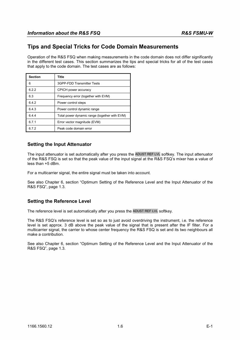
Tips and Special Tricks for Code Domain Measurements
Operation of the R&S FSQ when making measurements in the code domain does not differ significantly in the different test cases. This section summarizes the tips and special tricks for all of the test cases that apply to the code domain. The test cases are as follows: Section Title
6 3GPP-FDD Transmitter Tests
6.2.2 CPICH power accuracy
6.3 Frequency error (together with EVM)
6.4.2 Power control steps
6.4.3 Power control dynamic range
6.4.4 Total power dynamic range (together with EVM)
6.7.1 Error vector magnitude (EVM)
6.7.2 Peak code domain error
Setting the Input Attenuator
The input attenuator is set automatically after you press the ADUST REF LVL softkey. The input attenuator of the R&S FSQ is set so that the peak value of the input signal at the R&S FSQ’s mixer has a value of less than +5 dBm. For a multicarrier signal, the entire signal must be taken into account. See also Chapter 6, section “Optimum Setting of the Reference Level and the Input Attenuator of the R&S FSQ”, page 1.3. Setting the Reference Level
The reference level is set automatically after you press the ADUST REF LVL softkey. The R&S FSQ’s reference level is set so as to just avoid overdriving the instrument, i.e. the reference level is set approx. 3 dB above the peak value of the signal that is present after the IF filter. For a multicarrier signal, the carrier to whose center frequency the R&S FSQ is set and its two neighbours all make a contribution. See also Chapter 6, section “Optimum Setting of the Reference Level and the Input Attenuator of the R&S FSQ”, page 1.3.
R&S FSMU-W Information about the R&S FSQ
1166.1560.12 1.7 E-1
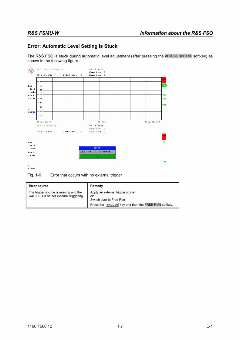
Error: Automatic Level Setting is Stuck
The R&S FSQ is stuck during automatic level adjustment (after pressing the ADJUST REF LVL softkey) as shown in the following figure:
Fig. 1-6 Error that occurs with no external trigger
Error source Remedy
The trigger source is missing and the R&S FSQ is set for external triggering.
Apply an external trigger signal or: Switch over to Free Run Press the TRIGGER key and then the FREE RUN softkey.

Information about the R&S FSQ R&S FSMU-W
1166.1560.12 1.8 E-1
Error: R&S FSQ is Overdriven After Automatic Level Adjustment
The R&S FSQ is experiencing an overflow after automatic level adjustment (after pressing the ADJUST REF LVL softkey) as shown in the following figure:
Fig. 1-7 Overflow trigger error
Error source Remedy
The R&S FSQ was not set to multicarrier but multiple carriers are present. (Multi Carrier).
Set the R&S FSQ to multicarrier mode and perform the automatic level setting again. Press the SETTINGS hotkey, then the NEXT key and the
MULTICARRIER ON OFF softkey. The green marker should switch from OFF to ON, and the R&S FSQ is now in multicarrier mode.
Press the RESULTS hotkey, then the ADJUST REF LVL softkey. The R&S FSQ will make the automatic level setting for multicarrier.
The R&S FSQ is set to the wrong frequency.
Set the R&S FSQ to the frequency of the base station. Press the FREQ key and enter the frequency in the input window.
The green marker should switch from OFF to ON, and the FSQ is now in multicarrier mode.
Press the RESULTS hotkey, then the ADJUST REF LVL softkey. The FSQ will make an automatic level setting for multicarrier.

R&S FSMU-W Information about the R&S FSQ
1166.1560.12 1.9 E-1
Error: INCORRECT PILOTS
The following error message will appear in the top screen: INCORRECT PILOT. The measured values
Fig. 1-8 Error screen for “Incorrect Pilot“
Error source Remedy
The antenna diversity settings of the base station and FSQ do not agree.
Set the proper antenna diversity. Press the Settings hotkey.
The softkeys for configuring the code domain parameters will appear.
Press the ANT DIV ON OFF softkey. The green marker will switch from ON to OFF or vice versa.
Press the ANT DIV 1 2 softkey. This is required only if ANT DEV was set to ON in the previous step. The green marker will switch from 1 to 2 or vice versa

Information about the R&S FSQ R&S FSMU-W
1166.1560.12 1.10 E-1
Error: (FRAME) SYNC FAILED
The following error message will appear in the top screen: SYNC FAILED. Only noise is displayed. The composite EVM is equal to 100 %.
Fig. 1-9 Error screen for “Sync Failed”
Error source Remedy
The FSQ is overdriven or underdriven.
Make an automatic level setting. Press the RESULTS hotkey, then the ADJUST REF LVL softkey.
The R&S FSQ will perform an automatic level setting.
The scrambling code of the base station and the R&S FSQ do not agree.
Set the correct scrambling code. Press the Settings hotkey.
The softkeys for configuring the code domain parameters will appear. Press the SCRAMBLING CODE softkey.
Enter the scrambling code for the base station as a hexadecimal number. Range of values: 0 to 1FFF Enter hexadecimal numbers by preceding them with a decimal point. Example: Enter the scrambling code 1F2a by typing 1.52.0.
The antenna diversity is set incorrectly.
Set the antenna diversity to the correct value. The settings of the base station and the R&S FSQ must agree. Press the Settings hotkey.
The softkeys for configuring the code domain parameters will appear. Press the ANT DIV ON OFF softkey.
The green marker will switch from ON to OFF or vice versa. Press the ANT DIV 1 2 softkey.
This is required only if ANT DEV was set to ON in the previous step. The green marker will switch from 1 to 2 or vice versa.
The antenna diversity is set incorrectly.
The synchronization of the R&S FSQ is set incorrectly. The R&S FSQ should synchronize to the synchronization channel (SCH) only if the common pilot channel (CPICH) is missing. This is the case in test model 4. Press the Settings hotkey.
The softkeys for configuring the code domain parameters will appear. Press the SNC TYPE CPICH SCH softkey.
The green marker will switch from CPICH to SCH or vice versa.

R&S FSMU-W Information about the R&S FSQ
1166.1560.12 1.11 E-1
Error source Remedy
The trigger offset or trigger polarity is set incorrectly.
Set the trigger offset to the correct value. The R&S FSQ needs a trigger signal in the range from 650 µs to 0 ns before the frame begins.
Press the TRIG key. The softkeys for triggering will appear.
Press the TRIGGER OFFSET softkey. Set the correct trigger offset in the input field. You can also set the correct time using the rotary knob. The time you set will go into effect immediately so that the correct time can be detected.
Change the polarity
Press the TRIG key. The softkeys for triggering will appear.
Press the POLARITY POS NEG softkey. The polarity will be switched and the green marker will switch from POS to NEG or vice versa.
Set the “FREE RUN” trigger mode.
Press the TRIG key. The softkeys for triggering will appear.
Press the FREE RUN softkey. The R&S FSQ’s trigger mode will be changed. In the FREE RUN trigger mode, you do not need a trigger offset.
Information about the R&S SMU R&S FSMU-W
1166.1560.12 1.12 E-1
Information about the R&S SMU
Calling Test Case Wizard
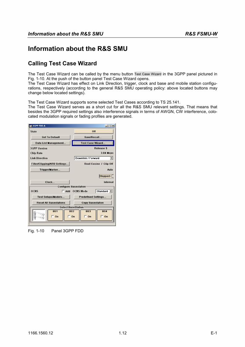
The Test Case Wizard can be called by the menu button Test Case Wizard in the 3GPP panel pictured in Fig. 1-10. At the push of the button panel Test Case Wizard opens. The Test Case Wizard has effect on Link Direction, trigger, clock and base and mobile station configu-rations, respectively (according to the general R&S SMU operating policy: above located buttons may change below located settings). The Test Case Wizard supports some selected Test Cases according to TS 25.141. The Test Case Wizard serves as a short cut for all the R&S SMU relevant settings. That means that besides the 3GPP required settings also interference signals in terms of AWGN, CW interference, colo-cated modulation signals or fading profiles are generated.
Fig. 1-10 Panel 3GPP FDD

Information about the R&S SMU R&S FSMU-W
1166.1560.12 1.13 E-1
Panel Test Case Wizard
The panel falls into three parts. In the upper part (Fig. 1-11) the user can select among
• the available test cases according to the TS 25.141,
• the degree of freedom of input settings (by Edit Mode),
• trigger and marker configurations,
• diversity and two routing schemes: – Route Baseband A to RF output port A. Baseband B is routed to RF output port B or its signal is added
to RF output port A (depending on the test case). The baseband A signal is disturbed by the modules FADER A or AWGN A (depending on the test case). The baseband B signal is disturbed by the mod-ules FADER B or AWGN B (depending on the test case).
– Route Baseband A to RF output port. Baseband A is routed to RF output port A or its signal is added to RF output port B (depending on the test case). The baseband A signal is disturbed by the modules FADER B or AWGN B (depending on the test case). The baseband B signal is disturbed by the mod-ules FADER A or AWGN A (depending on the test case).
• the scrambling scheme,
• the base station power class. In the right upper corner a graphic plot symbolizes the interference scenario defined by power level and freuqency offset. Test cases where R&S SMU hardware equipment is not sufficient are shown in grey color but are not selectable. RF power and frequency limitations of the R&S SMU hardware equipment restrict the set-ting ranges. The test cases require at least a basic configuration including:
• R&S SMU-K42: Digital standard 3GPP-FDD,
• R&S SMU-B11: Baseband generator / Arbitrary Waveform Generator with 16/64 MSamples,
• R&S SMU-B13: Baseband main module,
• R&S SMU-B10x: RF path 100 kHz - x GHz.
• R&S SMU-K62: Additive White Gaussian Noise, when a AWGN signal is required.
Fig. 1-11 Upper panel part

Information about the R&S SMU R&S FSMU-W
1166.1560.12 1.14 E-1
Test Case Sets the required test case.
The user can select from a list of test cases according to the chapter numbering in TS 25.141 (s. Table x) Remote-control command: :SOUR:BB:W3GP:TS25141:TCASe [TC642 | TC66 | TC72 | TC73 | TC74 | TC75 | TC76 | TC78 | TC821 | TC831 | TC832 | TC833 | TC834 | TC84 | TC85 | TC86 | TC881 | TC882 | TC883 | TC884 | TC891 | TC892 | TC893 | TC894]
Edit Mode Sets the wizards edit mode. The user can select from
• According to Standard: the settings are bound to TS 25.141, some items may be set to read only;
• User Definable: The user can choose the settings from a wider range, e.g. in terms of frequency offset, power level and so on.
Remote-control command: :SOUR:BB:W3GP:TS25141:EMODe [STANdard | USER]
Trigger Configuration Sets the R&S SMU trigger configuration. Triggers may be used to synchronize the R&S SMU by the other equipment. The user can choose from
• Auto: A test case dependent trigger configuration is in use. Unless otherwise stated the R&S SMU is set to ‘Armed Auto (External Trigger1)’,
• Unchanged: The previous trigger setting is not changed Remote-control command: :SOUR:BB:W3GP:TS25141:TRIGger [AUTO | PRESet]
Marker Configuration Sets the R&S SMU marker configuration. Markers may be used as trigger to synchronize the other equipment. The user can choose from
• Auto: A test case dependent marker configuration is in use,
• Unchanged: The previous marker setting is not changed Remote-control command: :SOUR:BB:W3GP:TS25141:TRIGger:OUTPut [AUTO | PRESet]
Diversity (if supported by the test case)
Sets the R&S SMU according to the base station diversity processing capability. The user can choose from:
• ON: The baseband signals are routed to either RF ports A and B,
• OFF: The baseband signals are routed to RF port A or B (depend-ing on Baseband A routing).
Remote-control command::SOUR:BB:W3GP:TS25141:RXDiversity [ON | OFF]
Baseband A Signal Routing (in case of no diversity)
Sets the routing of baseband A signal, that in most cases represents the ‘wanted signal’ (except from test case 6.6). The user can choose from
• To Path and RF Port A,
• To Path and RF Port B Remote-control command: :SOUR:BB:W3GP:TS25141:ROUTe [A | B]

Information about the R&S SMU R&S FSMU-W
1166.1560.12 1.15 E-1
Table 1-1 List of wizard supported test cases
Chapter Title Default setting
6 Transmitter ---------
6.4 Output power dynamics ---------
6.4.2 Power control steps
6.6 Transmit intermodulation
7 Receiver characteristics ---------
7.2 Reference sensitivity level
7.3 Dynamic range
7.4 Adjacent Channel Selectivity (ACS)
7.5 Blocking characteristics
7.6 Intermodulation characteristics
7.8 Verification of the internal BER calculation No BLER (BLER=0%)
8 Performance requirement ---------
8.2 Demodulation in static propagation conditions ---------
8.2.1 Demodulation of DCH Static Propagation
8.3 Demodulation of DCH in multipath fading conditions ---------
8.3.1 Multipath fading Case 1 Fading Case 1
8.3.2 Multipath fading Case 2 Fading Case 2
8.3.3 Multipath fading Case 3 Fading Case 3
8.3.4 Multipath fading Case 4 Fading Case 4
8.4 Demodulation of DCH in moving propagation conditions Moving propagation
8.5 Demodulation of DCH in birth/death propagation conditions Birth/Death propagation
8.6 Verification of the internal BLER calculation No BER (BER = 0%)
8.8 RACH performance ---------
8.8.1 RACH preamble detection in static propagation conditions Static propagation
8.8.2 RACH preamble detection in multipath fading case 3 Fading case 3
8.8.3 Demodulation of RACH message in static propagation condi-tions
Static propagation
8.8.4 Demodulation of RACH message in multipath fading case 3 Fading case 3
8.9 CPCH Performance ---------
8.9.1 CPCH access preamble and collision detection preamble de-tection in static propagation conditions
Static propagation
8.9.2 CPCH access preamble and collision detection preamble de-tection in multipath fading case 3
Fading case 3
8.9.3 Demodulation of CPCH message in static propagation condi-tions
Static propagation
8.9.4 Demodulation of CPCH message in multipath fading case 3 Fading Case 3
Scrambling Code (hex) Sets the base station or user equipment scrambling code figure (base
station identification). Remote-control command: :SOUR:BB:W3GP:TS25141:SCODe

Information about the R&S SMU R&S FSMU-W
1166.1560.12 1.16 E-1
Scrambling Mode Sets the scrambling mode.
Remote-control command: :SOUR:BB:W3GP:TS25141:SCODe:MODE [OFF | ON | LONG | SHORt]
Off Disables scrambling coding for test purposes. On (in case of
forward link only) Enables scrambling coding in case of forward link test setups only.
Long Scram-
bling Code (in case of reverse link only)
Sets the long scrambling code in case of reverse link test setups only.
Short Scram-
bling Code ( only modes DPCCH + DPDCH and PCPCH only)
Sets short scrambling code in case of reverse link test setups only. The short scrambling code is only standardized for DPCCH and DPDCH channels.
Power Class (if supported by the test case and if Edit Mode ‘According to Standard’)
Sets the base station power class. The user can choose from:
• Wide Area BS,
• Medium Range BS,
• Local Area BS Remote-control command: :SOUR:BB:W3GP:TS25141:BSPClass [WIDE | MEDium | LOCal]
The middle part displays the input/output parameters of the selected test case and further configuration entries besides the default settings. The following chapters give a detailed description of the test cases. After pressing the Apply Settings button at the bottom (Fig. 1-12) a partial reset (not a general R&S SMU reset) initializes the R&S SMU, which
• switches off all the baseband modules, fading modules, AWGN blocks, but the impairment settings of AWGN remain unchanged,
• does not switch the RF modules On or Off,
• does not alter any other configuration besides the active baseband modules, the fading modules, the AWGN blocks.
Next all the baseband modules, fading modules, AWGN blocks which are in use according to the entered test case are prepared for operation, and all the database and GUI settings are refreshed showing the current state.
Fig. 1-12 Lower panel part
Apply Settings Updates the R&S SMU settings according to the test case Remote-control command: :SOUR:BB:W3GP:TS25141:TCASe:EXECute
A few seconds later the R&S SMU is ready to start. For synchronisation reasons R&S SMU baseband A (and baseband B if the test case requires) are set to mode ‘armed auto external trigger1’. Unless oth-erwise noted the trigger delay is set equal to zero. Thus, the base station frame timing is able to syn-chronise the R&S SMU by an SFN (System Frame Number) periodic trigger. In case the R&S SMU of-fers a channel coded signal (e.g. as all the Reference Measurements Channels require) the base station shall emit an ‘SFN mod 4’ periodic trigger (see Fig. 1-13).

Information about the R&S SMU R&S FSMU-W
1166.1560.12 1.17 E-1
The R&S SMU itself is able to synchronize further measuring instruments by its Marker1 trace.
MeasuringInstrument
BaseStationBS frame
trigger
Marker 1 Trigger 1
R&S SMU
Fig. 1-13 R&S SMU synchronization by start trigger
Fig. 1-14 R&S SMU synchronization to clock master/slave
Note: When building up the measurement setups according to TS 25.141 it might be useful that all the instruments share a common reference clock. However, after PRESET the R&S SMU uses its internal clock reference by default. In order to feed in the clock of an external clock master the RF module configuration should be switched to external clock referency.
Before triggering the R&S SMU the user is able to change the settings. This applies particularly to RF power levels in order to compensate cable loss and additionally inserted attenuators. These RF power levels can easily be adjusted in the right upper corner of the SMU GUI. Table 1-2 gives a summary of all the steps required to have the R&S SMU test case signals sent.
Table 1-2 Operation Summary
• Push the button ‚Test Case Wizard’ in the 3GPP panel • Choose the required Test Case • Enter the test case directed settings, e.g. in terms of frequency, power level, … • Push the button ‘Apply Settings‘ • May change or further refine the setting results • Start the R&S SMU signal generation by an trigger impulse at connector TRIGGER1 Note: For safety reasons the RF is not active unless the button RF ON has not been pressed once.

Information about the R&S SMU R&S FSMU-W
1166.1560.12 1.18 E-1
Improvements on the Signal Quality
I/Q Settings
The I/Q blocks offer the possibility to change the internal baseband gain for improved ACLR perform-ance (see Fig. 1-15). In each I/Q block (A or B) that will be used for the test case
• Set Source to Internal Baseband and
• Set the internal Baseband Gain to 3 dB (Best For High 3GPP ACLR) or 6 dB (Best For Low Noise)
Fig. 1-15 Baseband Gain Setting for improved ACLR Performance

Information about the R&S SMU R&S FSMU-W
1166.1560.12 1.19 E-1
RF Level Settings
The RF blocks offer the possibility to manipulate the RF power level (see Fig. 1-16). In case the Automatic Level Control State is set to
• Auto (default configuration) the level control is automatically adapting but may causes increased intermodulation.
• Sample&Hold the internal level control deactivated and a single Search Once command should calibrate the RF output level.
The User Correction Settings enable the user to enter frequency dependent level correction figures into a list. By activating the State (On) this User Correction Data will increase the origin RF level by an frequency interpolated level offset.
Fig. 1-16 RF Level Setting for Level Control

R&S FSMU-W Notes on programming examples
1166.3363.12 1.20 E-1
Notes on programming examples
The programming examples in the description of the test cases describe the programming of the devices and serve as a basis for solving complex programming tasks. On the supplied CD, the programming examples are combined in a program (3gpp Sample Progams\bin\3gpp_cvi.exe or 3gpp_ansi.exe). Before the instrument is put into operation, this program must be copied into a user-selected directory of the controller. The program can be run, provided the PC has a driver for a GPIB card from National Instruments. ANSI-C was used as the programming language. Every measurement example is listed as a function in a separate file. A common graphical user interface (GUI) is used to call all measurement examples. There are two versions of the GUI:
• 3gpp_menu_cvi.c: uses the API of LabWindows/CVI (National Instruments)
• 3gpp_menu_ansi.c: uses only ANSI-C string routines The programs can thus be implemented in other languages or development environments as well. The GPIB bus is programmed in separate central functions contained in the FSMU_global module. The functions there address the GPIB bus via drivers from National Instruments. Encapsulation in the FSMU_global module makes porting to drivers of other GPIB bus manufacturers easy.
Fig. 1-17 Structure of example programs
This section describes the central functions contained in the FSMU_global module. IEC/IEEE bus addresses used
R&S FSQ: 28 R&S SMU: 20 The instrument addresses used are ex factory. If other addresses are used, the #defines for FSQ_PRIMARY_ADDR or SMU_PRIMARY_ADDR must be changed in the fsmu_global.c module.

R&S FSMU-W Notes on programming examples
1166.3363.12 1.21 E-1
Recommended settings in the GPIB driver from National Instruments
The recommended settings are in the NI-488.2 Settings tab:
Fig. 1-18 Recommended standard settings of the GPIB card"
Send EOI at end of Write: must be activated Terminate Read on EOS: must be deactivated SET EOI with EOS on Write: must be deactivated System Controller must be activated The other settings are system-dependent. The displayed values are the defaults. The following settings are recommended in the Advanced tab:
Fig. 1-19 Structure of example programs"
Automatic Serial Polling: must be deactivated Assert REN when SC (Remote Enable) must be activated The other settings are system-dependent. The displayed values are the defaults.

Notes on programming examples R&S FSMU-W
1166.3363.12 1.22 E-1
Functions for the R&S FSQ
The functions are used for initializing and resetting the instrument. In addition, conversion routines for converting the results of the R&S FSQ to C structures are also included. Fsmu_InitFsq
Initializes the access to the GPIB bus for the R&S FSQ. The primary and secondary address, timeout, EOT mode and EOI mode in the function are fixed. The #defines at the beginning of the module may have to be edited. If the analyzer cannot be initialized, the program is exited after issuing an error message. The analyzer is not yet programmed in this function.
Declaration: void Fsmu_InitFsq (int *ud) ;
Parameters: *ud Pointer to the GPIB handle for analyzer
Returned value: None Fsmu_CloseFsq
Queries the error queue of the R&S FSQ, informs the user in the event of an error, switches the R&S FSQ to local and closes the GPIB access for the R&S FSQ. The GPIB handle is no longer valid after the function has been called. Note: The reset is skipped after the function Fsmu_SetSkipReset has been called with
parameter 1, allowing the programs to run faster. Calling the function with parameter 0 switches the reset on again.
The FSMU_ibd and FSMU_ibd transducer tables are created if they do not exist. A total of 35 dB is assumed in the entire frequency range of the R&S FSQ.
Declaration: void Fsmu_CloseFsq (int ud) ;
Parameters: ud GPIB handle of the analyzer
Returned value: None Fsmu_SetupInstrumentFsq
Sets the R&S FSQ to the status required for the examples: • Executes a reset (if necessary, see description) • Sets the status registers • Loads the FSMU_ibd transducer table (is generated if necessary) • Sets the reference offset to 10 dB • Switches on the screen update • Sets the trigger to internal
Declaration: void Fsmu_SetupInstrumentFsq(int ud) ;
Parameters: ud GPIB handle of the analyzer
Returned value: None

R&S FSMU-W Notes on programming examples
1166.3363.12 1.23 E-1
Fsmu_ConvertFsqResultSummary The result summary of the R&S FSQ can be queried either in ASCII format (:FORMat:ASCii;) or in binary format (:FORMat REAL,32;). Transmission in ASCII format is slower, and the result must be converted. Binary format, however, requires that the compiler be able to process the Reals receive function in Intel IEEE format, which cannot always be defined in advance. The present function converts the string in ASCII format and stores the result in a structure (Fsq_ResultSummary, see page 1.34).
Declaration: int Fsmu_ConvertFsqResultSummary (char input_string [], Fsq_ResultSummary * summary) ;
Parameters: input_string: Result string of the R&S FS-K72 with the values of the result summary in ASCII format
*summary: The results in a C structure
Returned value: 0: An error occurred during conversion; all values were set to .200 1: No error occurred
Fsmu_ConvertFsqResultTrace
A trace of the R&S FSQ can be queried either in ASCII format or in binary format. Transmission in ASCII format is slower, and the result must be converted. Binary format, however, requires that the compiler be able to process the Floats processing function in Intel IEEE format, which cannot always be defined in advance. The present function converts the string in ASCII format and stores the result in an array of floats.
Declaration: int Fsmu_ConvertFsqResultTrace (char input_string [], float * summary, int size) ;
Parameters: input_string Result string of the R&S FS-K72 with the values of a trace in ASCII format
* summary The results in a float array
size The length of the array
Returned value: The number of converted values

Notes on programming examples R&S FSMU-W
1166.3363.12 1.24 E-1
Functions for the R&S SMU
The functions are used for initializing and resetting the instrument. In addition, functions for configuring the R&S SMU for simulating a base station are also included. Fsmu_InitSmu
Initializes the access to the GPIB bus for the R&S SMU. The primary and secondary address, timeout, EOT mode and EOI mode in the function are fixed. The #defines at the beginning of the module may have to be edited. If the generator cannot be initialized, the program is exited after issuing an error message. The generator is not yet programmed in this function.
Declaration: void Fsmu_InitSmu (int *ud) ;
Parameters: *ud Pointer to the GPIB handle for the generator
Returned value: None Fsmu_CloseSmu
Queries the error queue of the R&S SMU, informs the user in the event of an error, switches the R&S SMU to local and closes the GPIB access for the R&S SMU. The GPIB handle is no longer valid after the function has been called
Declaration: void Fsmu_CloseSmu (int ud) ;
Parameters: ud GPIB handle of the generator
Returned value: None Fsmu_SetupInstrumentSmu
Sets the R&S SMU to the status required for the examples: • Executes a reset (if necessary, see description) • Switches the R&S SMU off • Sets the trigger to internal • Sets the trigger mode to Auto • Sets trigger inhibit to 0 • Sets the frequency to the value specified in the parameter (resolution 1 Hz) • Sets the RF level to -2 dBm • Switches the 3GPP mode on – depending on the parameter, for simulating a base station
(INIT_DL) or a mobile phone (INIT_UL) Note: The reset is skipped after the function Fsmu_SetSkipReset has been called with
parameter 1, allowing the programs to run faster. Calling the function with parameter 0 switches the reset on again.
The generator is switched off after the function is called, and must be switched on by calling the functions Fsmu_SmuOn and Fsmu_Smu3GPPOn.
Declaration: void Fsmu_SetupInstrumentSmu (int ud, InitMode Mode, double freq)) ;
Parameters: ud GPIB handle of the analyzer Mode INIT_UL or INIT_DL freq Frequency in GHz
Returned value: None

R&S FSMU-W Notes on programming examples
1166.3363.12 1.25 E-1
Fsmu_SmuDiversity The R&S SMU switches antenna diversity off (mode = 0), to antenna 1 (mode = 1) or antenna 2 (mode = 2). If a parameter outside the permitted range is specified, diversity is switched off.
Declaration: void Fsmu_SmuDiversity (int ud, int mode) ;
Parameters: ud GPIB handle of the generator mode 0 to 2
Returned value: None Fsmu_SmuChannelPower
The level of the specified channel is set to the desired power. Channel numbers less than 1 are set to channel 1; channel numbers greater than 138 are set to channel 138. Analogously, the power is limited to values between -80 dBm and 0 dBm.
Declaration: void Fsmu_SmuChannelPower (int ud, int channel, double level) ;
Parameters: ud GPIB handle of the analyzer channel Channel (1 to 138) for which the power is to be set level Desired power in dBm (-80 to 0)
Returned value: None Fsmu_SmuRfRelPower
Increases or decreases the RF power of the R&S SMU by the specified value. Note: The parameter is not checked.
Declaration: void Fsmu_SmuRfRelPower (int ud, double level) ;
Parameters: ud GPIB handle of the generator level Desired power change in dB
Returned value: None Fsmu_SmuOn
Switches on channel A of the R&S SMU's RF output.
Declaration: void Fsmu_SmuOn (int ud) ;
Parameters: ud GPIB handle of the generator
Returned value: None Fsmu_Smu3GPPOn
The function writes a string from the buffer buf to the device with the handle ud. The output ends with the characters '\0'. If an error occurs during this process, it is reported to the user. This function is an enhancement compared with the National Instruments functions. Switches on the 3GPP mode of the R&S SMU
Declaration: void Fsmu_Smu3GPPOn (int ud) ;
Parameters: ud GPIB handle of the generator
Returned value: None

Notes on programming examples R&S FSMU-W
1166.3363.12 1.26 E-1
Functions for the GPIB bus
This section describes the functions used in the example programs for data traffic via GPIB. The names of the functions are based on the corresponding functions of the drivers from National Instruments. If GPIB drivers from another manufacturer are used, it suffices to adjust the functions in this section. The example programs access the GPIB bus solely via the functions listed in the following. All functions require a "ud" handle of the int type, which is generated in the functions Fsmu_InitFsq or Fsmu_InitSmu via the Fsmu_ibDev function. Fsmu_ibWrt
The function writes count values from the buffer buf to the device with the handle ud. If an error occurs during this process, it is reported to the user. This is an enhancement compared with the National Instruments functions.
Declaration: int Fsmu_ibWrt (int ud, void * buf, long count) ;
Parameter: ud GPIB handle for the device *buf Buffer to be written count Number of values to be written
Returned value: Value of the variable ibsta Fsmu_ibWrtln
The function writes a string from the buffer buf to the device with the handle ud. The output ends with the characters '\0'. If an error occurs during this process, it is reported to the user. This function is an enhancement compared with the National Instruments functions.
Declaration: int Fsmu_ibWrtln (int ud, void * buf) ;
Parameters: ud GPIB handle for the device: *buf Buffer to be written
Returned value: Value of the variable ibsta Fsmu_ibRd
The function reads up to count characters from the device with the handle ud and stores them in the buffer buf. The function stops reading when the EOI of GPIB occurs, but at the latest when count values have been read in. If an error occurs during this process, it is reported to the user. This is an enhancement compared with the National Instruments functions.
Declaration: int Fsmu_ibRd (int ud, void * buf, long count) ;
Parameters: ud GPIB handle for the device *buf Buffer to be written count Maximum number of values to be read
Returned value: Value of the variable ibsta

R&S FSMU-W Notes on programming examples
1166.3363.12 1.27 E-1
Fsmu_ibRdln The function reads up to count characters from the device with the handle ud and stores them in the buffer buf. The function stops reading when the EOI of GPIB occurs, but at the latest when count values have been read in. If the character last read in is CR (0xd) or LF (0xa), it is replaced by '\0'. If an error occurs during the read, it is reported to the user. This function is an enhancement compared with the National Instruments functions.
Declaration: int Fsmu_ibRdln (int ud, void * buf, long count) ;
Parameters: ud GPIB handle for the device *buf Buffer to be written count Maximum number of values to be read
Returned value: Value of the variable ibsta Fsmu_ibTmo
The function sets the timeout for the specified device or bus to the transferred value. The timeout applies to all subsequent bus operations. With a National Instruments driver, the predefined values of TNONE (off) and T10 us to T1000 s can be used as times. If an error occurs while the timeout is being set, it is reported to the user. This function is an enhancement compared with the National Instruments functions.
Declaration: int Fsmu_ibTmo (int ud, int TimeOut) ;
Parameters: ud GPIB handle for the device or for the bus TimeOut Timeout as specified in the #defines (TNONE, T10 us to T1000 s)
Returned value: Value of the variable ibsta Fsmu_ibGetTmo
The function reads out the timeout for the specified device or bus and transfers it to the calling function. The ibask function is used with drivers from National Instruments. If an error occurs while the timeout is being read, it is reported to the user. This function is an enhancement compared with the National Instruments functions.
Declaration: int Fsmu_ibGetTmo (int ud, int * TimeOut) ;
Parameters: ud GPIB handle for the device or for the bus *TimeOut Timeout as it is read out
Returned value: Value of the variable ibsta Fsmu_ibWaitForSRQ
The function sets the timeout for the specified device to the transferred value and waits for an SRQ. Subsequently it resets the timeout to the original value. It uses the functions Fsmu_ibGetTmo and Fsmu_ibSetTmo, as well as WaitSRQ of the National Instruments driver.
Declaration: int Fsmu_ibWaitForSRQ (int bd, int TimeOut) ;>
Parameters: ud GPIB handle for the device TimeOut Timeout, see Fsmu_ibTmo
Returned value: Value of the variable ibsta

Notes on programming examples R&S FSMU-W
1166.3363.12 1.28 E-1
Fsmu_ibRsp The function runs a serial poll on the specified bus and transfers the result in the parameter status_byte. It uses the functions Fsmu_ibGetTmo and Fsmu_ibSetTmo, as well as WaitSRQ of the drivers.
Declaration: int Fsmu_ibRsp (int ud, char * status_byte) ;
Parameters: ud GPIB handle for a bus status_byte: Response of the serial poll
Returned value: Value of the variable ibsta Fsmu_ibCheck
The function checks the global variable ibsta for errors. If an error has occurred, this is reported to the user and the program is exited, provided the value IBCHECK_TERMINATE was transferred in the parameter mode.
Declaration: static void Fsmu_ibCheck (int ud, int mode, char * ErrorMsg) ;
Parameters: ud GPIB handle for the device
Returned value: None
Side effect: The function terminates the program if an ibsta indicates an error and IBCHECK_TERMINATE is transferred as the parameter mode.
Fsmu_ibDev
The function opens a channel for a device on the bus and sets the primary and secondary address, timeout, EOI behavior and end-of-string behavior to the specified values. All specifications should remain unchanged, except the value for the primary address.
Declaration: static int Fsmu_ibDev (int boardID, int pad, int sad, int tmo, int eot, int eos) ;
Parameters: ud GPIB handle for the device pad Primary address of the device sad Secondary address of the device tmo Timeout for the device eot EOI behavior for the device eos End-of-string behavior for the device *listen Pointer to the response of the function
Returned value: Value of the variable ibsta Fsmu_ibLn
The function checks whether a device with the specified primary and secondary address can be addressed via the specified device handle. If no device can be addressed, 0 is stored in the parameter listen; otherwise a value unequal to 0.
Declaration: static int Fsmu_ibLn (int ud, int pad, int sad, short *listen) ;
Parameters: ud GPIB handle for the device pad Primary address of the device sad Secondary address of the device *listen Pointer to the response of the function
Returned value: Value of the variable ibsta

R&S FSMU-W Notes on programming examples
1166.3363.12 1.29 E-1
Fsmu_ibLoc Switches the device to local.
Declaration: static int Fsmu_ibLoc (int ud) ;
Parameters: ud GPIB handle for the device
Returned value: Value of the variable ibsta Fsmu_ibOnl
The channel for the specified device is closed and all resources for the device released. The GPIB handle loses its validity.
Declaration: static int Fsmu_ibOnl (int ud, int mode) ;
Parameters: ud GPIB handle for the device: mode 0: driver for the device is released Not 0: driver is not released
Returned value: Value of the variable ibsta Fsmu_ibConfig
General configuration function used in the present examples to switch off autopolling of the driver. If autopolling has already been deactivated in the driver, this function is not needed.
Declaration: static int Fsmu_ibConfig (int ud, int option, int value) ;
Parameters: ud GPIB handle for the device option Option of the driver to be configured value Value for the option with which the driver is configured
Returned value: Value of the variable ibsta Fsmu_DeviceCheckSystemErrors
Queries the error queue of the specified device and displays the entries. The entry "0, no error" is not displayed. The function can be used for debugging a program in order to locate faulty GPIB strings quickly.
Declaration: int Fsmu_DeviceCheckSystemErrors (int ud) ;
Parameters: ud GPIB handle for the device
Returned value: None Fsmu_WaitForDevice
Waits until a device has completed the preceding task. The function performs this by sending an *OPC? to the device and waiting for its response. If a timeout or other error occurs, it is reported to the user and FSMU_WARNING is returned; otherwise FSMU_OK is returned.
Declaration: int Fsmu_WaitForDevice (int ud) ;
Parameters: ud GPIB handle for the device
Returned value: FSMU_WARNING or FSMU_OK

Notes on programming examples R&S FSMU-W
1166.3363.12 1.30 E-1
User interface
Data is input and output by one central function. Fsmu_MessageBox
Implementation via LabWindows/CVI Outputs the two strings and waits for a mouse click.
Fig. 1-20 Example of the Fsmu_MessageBox – LabWindows/CVI version
Implementation via ANSI-C Outputs the two strings and waits for ENTER.
Fig. 1-21 Example of Fsmu_MessageBox – ANSI version"
Declaration: void Fsmu_MessageBox (const char title[], const char message[]);
Parameters: title String of the header message Output string
Returned value: None Fsmu_HideMessageBox
Auxiliary function for Fsmu_MessageBox: It is called by the callback function of the OK button and sets the s_MessageBoxFlag flag to 0. The routine is only needed in the implementation with LabWindows/CVI.
Declaration: void Fsmu_HideMessageBox (void) ;
Parameters: None
Returned value: None
R&S FSMU-W Notes on programming examples
1166.3363.12 1.31 E-1
Fsmu_MessageHandle Auxiliary function for Fsmu_MessageBox: It transfers the handle graphic for outputting text to the module. The routine is only needed in the implementation with LabWindows/CVI.
Declaration: void Fsmu_MessageHandle (int handle) ;
Parameters: handle Handle for the Fsmu_MessageBox window
Returned value: None

Notes on programming examples R&S FSMU-W
1166.3363.12 1.32 E-1
Functions for internal sequence control
The functions described in this section are used for controlling the sequence of the example programs. These functions can set and query the value of static variables. All static variables have useful default values. Fsmu_GetMultiCarrier
The function indicates whether a multicarrier or a single carrier base station is being tested.
Declaration: int Fsmu_GetMultiCarrier (void) ;
Parameters: None
Returned value: Value of the module-global variable s_MultiCarrierMode 1: Multicarrier is on 0: Single carrier
Fsmu_SetMultiCarrier
Description see Parameters.
Declaration: void Fsmu_SetMultiCarrier (int mode) ;
Parameters: 1: The module-global variable s_MultiCarrierMode is set All others The module-global variable s_MultiCarrierMode is reset
Returned value: None Fsmu_GetBtsEmulation
The function indicates whether the base station is emulated by the R&S SMU.
Declaration: int Fsmu_GetBtsEmulation (void) ;
Parameters: None
Returned value: Value of the module-global variable s_MultiCarrierMode 1: BTS is emulated by the R&S SMU => The R&S SMU is configured as a BTS in the tests 0: Users are prompted to configure the BTS
Fsmu_SetBtsEmulation
Description see Parameters.
Declaration: void Fsmu_SetBtsEmulation (int mode) ;
Parameters: 1: The module-global variable s_BtsEmulationMode is set All others The module-global variable s_BtsEmulationMode is reset
Returned value: None

R&S FSMU-W Notes on programming examples
1166.3363.12 1.33 E-1
Fsmu_GetSkipReset Declaration: int Fsmu_GetSkipReset (void) ;
Parameters: None
Returned value: Value of the module-global variable s_SkipResetMode 1: Instrument reset is skipped in the Fsmu_SetupInstrumentSmu or the Fsmu_SetupInstrumentFsq function 0: Reset is always performed
Fsmu_SetSkipReset The function indicates whether the instrument reset is to be skipped (see Parameters).
Declaration: void Fsmu_SetSkipReset (int mode) ;
Parameters: 1: The module-global variable s_SkipResetMode is set All others The module-global variable s_SkipResetMode is reset
Returned value: None

Notes on programming examples R&S FSMU-W
1166.3363.12 1.34 E-1
Data types
Fsmu_InitMode The enum notifies the Fsmu_SetupInstrumentSmu function whether the R&S SMU is to be configured for the uplink or downlink.
Declaration: /* define, how initialisation should be done */ typedef enum INIT_DL, INIT_UL } Fsmu_InitMode ;
Fsq_ResultSummary
The results of the K72 result summary are stored in the result summary. On Intel systems, the results of the R&S FSQ can be read directly into the specified structure if the compiler used supports the IEC/IEEE float format (which is the case with LabWindows/CVI from National Instruments and Visual C from Microsoft). This feature is used in the test case examples. ASCII format must be used on machines with big endian format. This is clearly shown in the EVM test case using the function Fsmu_ConvertFsqResultSummary (see page 1.22).
Declaration:
/* summary result is returned in the following string */ /* <composite EVM>,<peak CDE>,<carr freq Error>,<chip rate error>, * <total power>,<trg to frame>,<EVM peak channel>,<EVM mean channel>, * <class>, <channel number>,<power abs. channel>,<power * rel. channel>,<timing offset>, <I/Q offset>,<I/Q imbalance> */ typedef struct { float composite_evm ; /* % */ float peak_domain_error ; /* dB */ float carr_freq_error; /* Hz */ float chip_rate_error; /* ppm */ float total_power; /* dBm */ float trg_to_frame; /* µs */ float evm_peak_channel; /* % */ float evm_mean_channel; /* % */ float Class; /* spreading number */ float channel_number; /* code of channel */ float power_abs_channel; /* dBm */ float power_rel_channel; /* dB */ float timing_offset; /* chips */ float IQ_offset; /* % */ float IQ_imbalance; /* % */
} Fsq_ResultSummary ; power_step
Declaration: Local in the function power_control_steps_aggregated
/* Result, as returned by FSQ in binary format */ typedef struct { float index ; float level ; } power_step ;

R&S FSMU-W Notes on programming examples
1166.3363.12 1.35 E-1
Structure for recording the power control steps (in the R&S FSQ: Power Steps versus Time) with binary data transmission. See Fsmu_SetupInstrumentSmu on page 1.34.
peak_value
Structure for recording the peak listen with binary data transmission (see page 1.34).
Declaration:
in spectrum emission mask und spurious emissions /* one element of the peak list as returned by the FSQ */ typedef struct { float frequency ; /* Hz frequency of peak */ float level ; /* dB level of peak */ float delta ; /* dB delta to limitline */ } peak_value ;


R&S FSMU-W Contents
1166.1560.12 I-2.1 E-1
Contents 2 Test Setup............................................................................................................ 2.1
Basic Setup .......................................................................................................................................2.1 Trigger ...............................................................................................................................................2.2
R&S FSQ Trigger Circuitry.......................................................................................................2.2 R&S SMU Trigger Circuitry ......................................................................................................2.3
Reference Frequency.......................................................................................................................2.4 Measurements Only with the R&S FSQ .........................................................................................2.6
Standard Test Setup with the R&S FSQ..................................................................................2.6 Test Setup with the Two-channel R&S SMU..................................................................................2.7 Default Instrument Settings ............................................................................................................2.8
Default R&S FSQ Setting for Measurements on 3GPP Base Stations ...................................2.8 Default State of the R&S SMU for Measurements on 3GPP Base Stations............................2.9
List of illustrations Fig. 2-1 Basic setup with the R&S SMU and R&S FSQ .................................................................... 2.1 Fig. 2-2 R&S FSQ triggering.............................................................................................................. 2.2 Fig. 2-3 R&S SMU triggering ............................................................................................................. 2.3 Fig. 2-4 R&S FSQ test setup with external reference frequency....................................................... 2.4 Fig. 2-5 Screen message of the R&S FSQ when the external reference frequency is missing ........ 2.5 Fig. 2-6 Standard test setup for measurements with the R&S FSQ.................................................. 2.6 Fig. 2-7 Basic setup with the R&S FSQ and the two-channel R&S SMU.......................................... 2.7


R&S FSMU-W Basic Setup
1166.1560.12 2.1 E-1
2 Test Setup
Basic Setup
Fig. 2-1 shows the test setup used for most measurements. However, for most applications it is sufficient to use solely the R&S SMU or the R&S FSQ. You can determine the required test setups from the basic setup described in Fig. 2-1 or from the description that follows. Test setups that occur in only one measurement configuration are described together with the measurement in chapter 9, 3gpp_tx_tests.doc.
The attenuation of attenuator R1 must be large enough that the max. permissible input level of 30 dBm is not exceeded. The input power at the R&S FSQ must not exceed 30 dBm. Attenuator R1 must be dimensioned accordingly.
Connect the RF output (channel A) of the R&S SMU directly with the input of the base station receiver. For many measurements, the instruments of the R&S FSMU-W require a trigger signal from the base station. The description of the circuitry and application of the trigger signal is provided in the section Trigger on page 2.2.
Fig. 2-1 Basic setup with the R&S SMU and R&S FSQ

Trigger R&S FSMU-W
1166.1560.12 2.2 E1
Trigger
Many measurements require that the measurement instruments be synchronized to the base station by means of a trigger. With the R&S FSQ, a trigger is not absolutely necessary, except for the power control steps measurement, 6.4.2. However, triggering increases the speed of the measurements in the code domain. With the R&S SMU, a trigger is necessary in all cases in which the R&S SMU generates channel-coded signals. This is the case for all tests in sections 7 and 8 of TS25.141. R&S FSQ Trigger Circuitry Connect the frame trigger output of the base station with the input EXT TRIGGER / GATE IN of the R&S FSQ. Fig. 2-2 shows the test setup and location of the trigger input connector.
SCPI
625 SCPI
I / Q DATA OUT
REF IN1...20 MHz REF OUT
AUX CONTROL
IEC 2
625SWEEP
EXT TRIGGER/GATE IN MOUSE MONITOR COM LPT
100 - 240 VAC
3.1 - 1.3 A
IEC 2
LAN
REF OUT640 MHz
IF OUT20.4 MHz
IF OUT404.4 MHz
VIDEOOUT
Fig. 2-2 R&S FSQ triggering
R&S FSQ settings:
With the R&S FSQ, use only the Free Run or External trigger types when carrying out measurements of 3GPP base stations. Measurements in the code range are usually faster with external triggering than with internal triggering since it is easier to search for the beginning of the frame.
Set the trigger type to Free Run. This trigger type is on after pressing Preset.
Press the TRIG key.
Press the FREE RUN softkey. The softkey is highlighted in green.
Set the trigger type to External.
Press the TRIG key.
Press the External softkey. The softkey is highlighted in green.
1. Compensate for the analog delays between the trigger event and the beginning of the frame. Press the TRIGGER OFFSET softkey.

R&S FSMU-W Trigger
1166.1560.12 2.3 E-1
R&S SMU Trigger Circuitry
The measurements in chapters 7 and 8 require that the R&S SMU be triggered externally from the base station. Fig. 2-3 shows the test setup and location of the trigger input connector.
1141.2005.02VECTOR SIGNAL GENERATOR
SETUP
HELP
PRE-SET
LOCAL
HCOPY
FREQ FILELEVEL MENU
ON/OFFMOD
ON/OFFRF ON/OFF
TOGGLE
DIA-GRAM
ESC
µV
BM / µ
dBµV
AG / n7
abc8
def9
ghi4
jkl5
mno6
pqrs mVk / m
C
1tuv2
wxyz3
E
* dB(m)1
D
0F
+/-
INSERT
SMU 200A .
INFO
CULATERECAL-
x
CLOSE
HIDE
REARR
WINBAR
USB
MADE IN GERMANY
ENTERSPACEBACK-
#... A a
RF 50
BASENSOR
CLOCK
I
Q
DATA
MARKER1 2 TRIGGER 1
Fig. 2-3 R&S SMU triggering
R&S SMU settings:
With the R&S SMU, use only the Free Run or External trigger types when carrying out measurements of 3GPP base stations. Measurements in the code range are usually faster with external triggering than with internal triggering since it is easier to search for the beginning of the frame.
Set the trigger type to Free Run. This trigger type is on after pressing Preset.
Press the TRIG key.
Press the FREE RUN softkey. The softkey is highlighted in green.
Set the trigger type to External. Press the TRIG key:
Press the External softkey. The softkey is highlighted in green.
Compensate for the analog delays between the trigger event and the beginning of the frame: Press the TRIGGER OFFSET softkey.

Reference Frequency R&S FSMU-W
1166.1560.12 2.4 E1
Reference Frequency
With the R&S SMU, the internal reference is sufficient. With the R&S FSQ, the optional oven-controlled crystal oscillator (OCXO) is sufficient for all measurements. A high-precision reference frequency (max. error: < 5E-9) is recommended only for test 6.3, frequency error. Connect the reference frequency output with the external reference frequency input of the R&S FSQ at the rear of the R&S FSQ. Fig. 2-4 shows the test setup and location of the external reference input connector.
SCPI
625 SCPI
I / Q DATA OUT
REF IN1.. .20 MHz REF OUT
AUX CONTROL
IEC 2
625SWEEP
EXT TRIGGER/GATE IN MOUSE MONITOR COM LPT
100 - 240 VAC
3.1 - 1.3 A
IEC 2
LAN
REF OUT640 MHz
IF OUT20.4 MHz
IF OUT404.4 MHz
VIDEOOUT
USB
USB
Fig. 2-4 R&S FSQ test setup with external reference frequency
Switch on the external reference frequency of the R&S FSQ. Do not change the reference frequency setting after you have pressed the preset key!
Press the SETUP key.
Press the FREFERENCE INT EXT softkey. The green highlighting of the softkey switches from INT to EXT.
Switch on the internal reference frequency of the R&S FSQ. Do not change the reference frequency setting after you have pressed the preset key!
Press the SETUP key.
Press the FREFERENCE INT EXT softkey. The green highlighting of the softkey switches from EXT to INT.
Note: If the external reference frequency signal is missing, the status signal EXREF will be displayed on the screen of the R&S FSQ. Synchronization with the measurement signal is often not possible in this case, as shown in the following diagram.

R&S FSMU-W Reference Frequency
1166.1560.12 2.5 E-1
Fig. 2-5 Screen message of the R&S FSQ when the external reference frequency is missing

Measurements Only with the R&S FSQ R&S FSMU-W
1166.1560.12 2.6 E1
Measurements Only with the R&S FSQ
Standard Test Setup with the R&S FSQ
Fig. 2-6 shows the test setup commonly used for measurements only with R&S FSQ. The use of the external trigger is described in the section R&S FSQ Trigger Circuitry on page 2.2. The use of the reference frequency is described in the section Reference Frequency on page 2.4. Connect the RF input of the R&S FSQ with the RF output of the base station by means of an attenuator. The attenuation of the attenuator R1 must be large enough that the max. permissible R&S FSQ input level of 30 dBm is not exceeded.
Fig. 2-6 Standard test setup for measurements with the R&S FSQ
The input power on the R&S FSQ must not exceed 30 dBm. Attenuator R1 must be dimensioned accordingly.

R&S FSMU-W Test Setup with the Two-channel R&S SMU
1166.1560.12 2.7 E-1
Test Setup with the Two-channel R&S SMU
The R&S SMU can be equipped with two optional RF outputs. In addition to the uplink signal of the R&S SMU, one or more interferers can then be generated. Fig. 2-7 shows the testup commonly used for most measurements. The outputs of the R&S SMU are routed directly to the receiver of the base station via a power splitter.
Fig. 2-7 Basic setup with the R&S FSQ and the two-channel R&S SMU
Default Instrument Settings R&S FSMU-W
1166.1560.12 2.8 E1
Default Instrument Settings
This section describes instrument settings that are frequently used. These settings must be made to enable the instruments to carry out the measurements directly. Optional steps are marked with (opt) where applicable. Default R&S FSQ Setting for Measurements on 3GPP Base Stations
1. Reset the instrument. Press the PRESET key.
The instrument is in its default state.
2. Load a suitable transducer table (opt). You can skip this step if the attenuation of the external circuitry is automatically included in the result.
Press the SETUP key.
Press the TRANSDUCER softkey. A selection window will display the stored transducer tables.
Choose the desired table by means of the or keys and select it via the ENTER key. The desired table is marked with . If you press the ENTER key again, the transducer table is deactivated.
Press the ESC key. The selection of the transducer table is terminated.
3. Set a fixed value for the transfer function (opt). You can skip this step if the attenuation of the external circuitry is automatically included in the result or if the transducer table contains all frequency correction data.
Press the AMPT key. The amplitude menu opens.
Press the NEXT key. The side menu of the amplitude menu opens.
Press the REF LEVEL OFFSET softkey.
Enter the desired external attenuation in the entry field using the numeric keypad (10 in the example) and terminate with the dB key.
4. Set the center frequency to the frequency of the base station. Press the FREQ key.
The frequency menu opens.
Enter the desired frequency in the entry field using the numeric keypad and terminate by pressing the unit key. Example: 2140 MHz.
5. Start the 3GPP FDD measurement application for base stations. Press the 3G FDD BS hotkey. If this hotkey is not at the lower part of the screen, press the MORE
hotkey until the 3G FDD BS hotkey is displayed.

R&S FSMU-W Default Instrument Settings
1166.1560.12 2.9 E-1
Default State of the R&S SMU for Measurements on 3GPP Base Stations
1. Reset the instrument. Press the PRESET key.
The instrument is in its default state.
2. Load a suitable user correction table (opt). You can skip this step if the attenuation of the circuitry is automatically included in the result.
Press the SETUP key.
Select the RF/A Mod menu. The menu for entering the user correction data is displayed.
Select the User Correction Data… menu. You can now either enter new data or call the file manager.
Call the File Manager… menu A list of the previously selected user correction data sets and a list of the currently available data sets are displayed.
Select the desired data set and confirm with ENTER .
Select State . OFF changes to ON, and the selected user correction table is activated.
Press the ESC key. The selection of the transducer table is terminated.
3. Set the center frequency to the receive frequency of the base station. Press the FREQ key.
The frequency menu is ready for entries.
Enter the desired frequency in the entry field using the numeric keypad and terminate by pressing the unit key. Example: 2140 MHz.
4. Set the transmission level. Press the LEVEL key.
The level menu is ready for entries.
Enter the desired level in the entry field using the numeric keypad and terminate by pressing the unit key. Example: -90 dBm.
Press the ESC key. The R&S SMU is in its default state.
5. Start the 3GPP FDD measurement application for base stations. Select the Baseband config… menu.
Select the 3GPP FDD… menu. The basic menu for configuring the 3GPP FDD application is displayed.

R&S FSMU-W Contents
1166.1560.12 I-3.1 E-1
Contents
3 Frequency Correction of the Test Setup........................................................... 3.1 Preliminary Remarks........................................................................................................................3.1 Correction by Entering a Level Offset............................................................................................3.2
Entering a Fixed Attenuation Value for the Test Setup in the FSQ .........................................3.2 Entering a Fixed Attenuation Value for the Test Setup in the SMU.........................................3.2
Correction of the Frequency Response of the Test Setup ..........................................................3.2 Basic Concept ..........................................................................................................................3.2 Steps for Measuring the Frequency Response Using the FSMU-W .......................................3.3
Normalizing the Instruments and the Auxiliary Cable....................................................3.3 Recording the Frequency Response of the Test Setup.................................................3.6 Storing the Correction Values........................................................................................3.7 Using the Correction Values ..........................................................................................3.7
Sample Program...............................................................................................................................3.8 List of illustrations Fig. 3-1 Basic test setup....................................................................................................................... 3.2 Fig. 3-2 Rear connection of the R&S SMU and R&S FSQ to the scalar network analyzer ................. 3.3 Fig. 3-3 Test setup during normalization.............................................................................................. 3.4 Fig. 3-4 Screenshot from the normalization measurement” ................................................................. 3.5 Fig. 3-5 Screenshot after normalization ............................................................................................... 3.6 Fig. 3-6 Test setup when measuring the frequency response of the cable to the R&S FSQ .............. 3.6


R&S FSMU-W Preliminary Remarks
1166.1560.12 3.1 E-1
3 Frequency Correction of the Test Setup
Preliminary Remarks
The levels displayed using the R&S FSQ and R&S SMU will refer to the connector on the instrument if no further measures are taken. As a general rule, however, it is necessary to take special measures to correct the frequency response of the test setup. The R&S FSMU-W allows you to choose among several possibilities in this regard:
• Manual correction of the measurement result: The frequency response of the test setup is added to the measured value or the setting of the level in the R&S SMU is corrected by the amount of the frequency response.
• Correction by entering a level offset (1 reference point) in the instruments: This makes it possible to correct the measured value at a single frequency very quickly. If the frequency response of the test setup can be neglected in the frequency range of interest, this method offers the fastest approach.
• Measurement of the frequency response of the external circuitry and taking into account of the measured frequency response in the equipment. In general, this is the most precise technique but it is also the most complex. The complexity can be minimized by using the “External Generator Control” Option (a standard feature of the R&S FSMU-W).
• A combination of all of these is possible. This chapter describes how you can automatically take into account the frequency response of the test setup in the displayed levels.

Correction by Entering a Level Offset R&S FSMU-W
1166.1560.12 3.2 E-1
Correction by Entering a Level Offset
Correction by entering a level offset into the instruments will always make sense if the frequency response of the test setup can be neglected in the frequency range of interest or if the absolute measured level is not important. This will be the case, for example, when making signal quality measurements (EVM, PCDE, etc). On the stimulus side, this applies to the measurement of the power control steps, for example. Entering a Fixed Attenuation Value for the Test Setup in the R&S FSQ
1. Set a fixed value for the transfer function Press the AMPT key.
The Amplitude menu should open.
Press the NEXT key. The side menu for the Amplitude menu should appear.
Press the REF LEVEL OFFSET softkey.
Use the keypad to enter the desired external attenuation in the input field (e.g. 10) and complete your entry by pressing the dB key. Use positive numbers to enter attenuation values.
Entering a Fixed Attenuation Value for the Test Setup in the R&S SMU
2. Set a fixed value for the transfer function Select Config… in the RF/A MOD A menu.
The menu for RF module A and the analog module will appear.
Select LEVEL/EMF… The menu for configuring the RF output will appear.
There, enter the desired level offset (e.g. -10 dBm) in the Offset menu. Use negative numbers to enter attenuation values.
Correction of the Frequency Response of the Test Setup
Basic Concept
The basic circuit that connects the R&S FSMU-W to the base station is shown Fig. 3-1.
Fig. 3-1 Basic test setup

R&S FSMU-W Correction of the Frequency Response of the Test Setup
1166.1560.12 3.3 E-1
In the R&S FSQ, you can take the frequency response of the “FSQ Cable” into account in the measurement by using what is known as “transducer factors”. In the R&S SMU, the corresponding table is known as the “user correction table”. The R&S FSQ’s transducer tables can be created with this configuration and can be directly stored out of the measurement trace. You can measure the frequency response of the cables using the R&S FSMU-W and store the result in the R&S FSQ in the form of a transducer table. Using an external program, the R&S FSQ’s transducer table can be transferred to a user correction table in the R&S SMU. For this measurement, the R&S SMU and R&S FSQ are operated with option FSP-B10 (“External Generator Control”) as a scalar network analyzer.
Fig. 3-2 Rear connection of the R&S SMU and R&S FSQ to the scalar network analyzer
The following table lists the pin allocation in the control cable between the R&S FSQ and R&S SMU: Cable 1103.9735.00 Instrument
Designation Type Instrument Connection
- 9-pol. D-Sub R&S FSQ AUX-Control
TRIGGER BNC SMU Instrument Trigger
BLANK BNC SMU User 1
MARKER BNC - -
In addition, the R&S FSQ’s 2nd GPIB bus must be connected to the R&S SMU’s GPIB bus via the supplied GPIB bus cable. Steps for Measuring the Frequency Response Using the R&S FSMU-W
This section explains how to measure the frequency response of the test setup using the R&S FSMU-W and how to take it into account in the measured values. The numbers given in the example are based on a setup in the inband frequency range. Normalizing the Instruments and the Auxiliary Cable
During the first step, the frequency response of the R&S SMU, R&S FSQ and an auxiliary cable are recorded. This frequency response is subtracted from the frequency response (recorded subsequently) of the test setup including the equipment so that the frequency response of the test setup remains. Fig. 3-3 shows the connections.

Correction of the Frequency Response of the Test Setup R&S FSMU-W
1166.1560.12 3.4 E-1
Fig. 3-3 Test setup during normalization
The auxiliary cable that is shown must be reused in all of the further measurement procedures. All of the required steps are listed below:
1. Set the network mode Press the NETWORK hotkey.
The softkeys for configuring the network mode will appear.
Press the NEXT key. The side menu for the settings will open.
2. Set the generator Press the EXT SOURCE softkey.
The softkeys for configuring the external generator will appear.
Press the SELECT GENERATOR softkey. The selection menu for configuring the external generator will appear.
Select the generator SMU03B31 in the menu under Type.
Select the TTL Interface in the menu under IFC.
Press the FREQUENCY SWEEP softkey. The selection menu for configuring the frequency sweep will appear.
In the menu under State, press ENTER to activate the frequency sweep.
In the menu under POWER [dBm], set the desired output level of the R&S SMU.
Press ESC twice. This will cause the two menus to disappear.
Press the EXT SRC ON OFF softkey. The green marker will switch from OFF to ON and the frequency sweep will be initiated.
3. Set the frequency range Press the FREQ hotkey.
The softkeys for entering the sweep frequencies will appear.
Press the START softkey. Enter the start frequency in the field, e.g. 2100 MHz.
Press the STOP softkey. Enter the stop frequency in the field, e.g. 2180 MHz.
4. Set the number of measurement points in the sweep (opt.) You can skip this item if you do not wish to change the default setting for the number of measurement points (= 625).
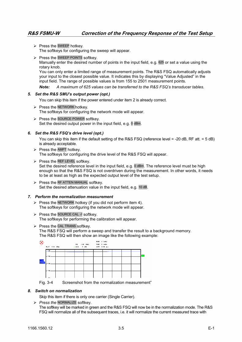
R&S FSMU-W Correction of the Frequency Response of the Test Setup
1166.1560.12 3.5 E-1
Press the SWEEP hotkey. The softkeys for configuring the sweep will appear.
Press the SWEEP POINTS softkey. Manually enter the desired number of points in the input field, e.g. 625 or set a value using the rotary knob. You can only enter a limited range of measurement points. The R&S FSQ automatically adjusts your input to the closest possible value. It indicates this by displaying “Value Adjusted” in the input field. The range of possible values is from 155 to 2501 measurement points. Note: A maximum of 625 values can be transferred to the R&S FSQ’s transducer tables.
5. Set the R&S SMU’s output power (opt.) You can skip this item if the power entered under item 2 is already correct.
Press the NETWORK hotkey. The softkeys for configuring the network mode will appear.
Press the SOURCE POWER softkey. Set the desired output power in the input field, e.g. 0 dBm.
6. Set the R&S FSQ’s drive level (opt.) You can skip this item if the default setting of the R&S FSQ (reference level = -20 dB, RF att. = 5 dB) is already acceptable.
Press the AMPT hotkey. The softkeys for configuring the drive level of the R&S FSQ will appear.
Press the REF LEVEL softkey. Set the desired reference level in the input field, e.g. 0 dBm. The reference level must be high enough so that the R&S FSQ is not overdriven during the measurement. In other words, it needs to be at least as high as the expected output level of the test setup.
Press the RF ATTEN MANUAL softkey. Set the desired attenuation value in the input field, e.g. 10 dB.
7. Perform the normalization measurement Press the NETWORK hotkey (if you did not perform item 4).
The softkeys for configuring the network mode will appear.
Press the SOURCE CAL softkey. The softkeys for performing the calibration will appear.
Press the CAL TRANS softkey. The R&S FSQ will perform a sweep and transfer the result to a background memory. The R&S FSQ will then show an image like the following example:
Fig. 3-4 Screenshot from the normalization measurement”
8. Switch on normalization Skip this item if there is only one carrier (Single Carrier).
Press the NORMALIZE softkey. The softkey will be marked in green and the R&S FSQ will now be in the normalization mode. The R&S FSQ will normalize all of the subsequent traces, i.e. it will normalize the current measured trace with

Correction of the Frequency Response of the Test Setup R&S FSMU-W
1166.1560.12 3.6 E-1
respect to the background memory stored under item 6. This will happen until you press NORMALIZE again.
9. Determine the position of the reference line (opt.) You can skip this item if there are no amplifiers present in the measurement path.
Press the REF VALUE POSITION softkey. Enter the desired position in % in the input field or with the rotary knob, e.g. 50 %. This will shift the position of the measurement trace on the screen so that measured values > 0 dB can also be displayed.
The R&S FSQ will show an image like the following example:
Fig. 3-5 Screenshot after normalization
Recording the Frequency Response of the Test Setup
The second step involves recording the frequency response of the test setup. This needs to be handled separately for each measurement path. The R&S FSQ and R&S SMU are interconnected via each measurement path with the auxiliary cable. A normalized measurement of the transmission behaviour of the test setup is then performed. The transfer function of the measurement path is then displayed in the trace. Fig. 3-5 shows the connections.
Fig. 3-6 Test setup when measuring the frequency response of the cable to the R&S FSQ
The frequency response measured during this step is stored in the R&S FSQ as a transducer table or transferred to the R&S SMU as a user correction table. It can then be used for frequency correction of the devices.

R&S FSMU-W Correction of the Frequency Response of the Test Setup
1166.1560.12 3.7 E-1
Storing the Correction Values
In the R&S FSQ: The currently displayed measurement trace can be stored in the R&S FSQ directly as a transducer table. It can then be used in subsequent measurements to correct the frequency response of the test setup.
The measurement trace can be saved as a transducer table only if the number of sweep points is not greater than 625.
1. Store trace values as correctiontable Press the NETWORK hotkey:
The softkeys for configuring the network mode will appear.
Press the SOURCE CAL softkey. The softkeys for performing the calibration will appear.
Press the SAVE AS TRD FACTOR softkey. Pressing this softkey creates a transducer factor of up to 625 points out of a normalized measurement trace. The number of entries in the transducer table can be defined by means of the softkey SWEEP COUNT. The frequency points are spaced with equal distances between the start and stop frequencies. The transducer factor can be edited by means of the softkey TRANSDUCER in SETUP menu. SAVE AS TRD FACTOR is available only if normalization is switched on.
In the R&S SMU: The currently displayed measurement trace can be read out from the R&S FSQ and stored in the R&S SMU as a user correction table. An external program is required for this purpose. The CD contains a sample program and its source text can be found in the section on Frequency Correction of the Test Setup, page 3.8. Using the Correction Values
In the R&S FSQ
1. Load a transducer table Press the SETUP key.
Press the TRANSDUCER softkey.
A selection window with the stored transducer tables should appear.
Select the desired table using the or key and press ENTER. Mark the selected table with the mark. Press the ENTER key again to deactivate the transducer table.
Press the ESC key.
In the R&S SMU
1. Load a transducer table Select Config… in the RF/A MOD A menu.
The menu for RF module A and the analog module will appear.
Select User Correction … The menu for configuring the RF output will appear.
There, select Select User Correction Data in the User Correction Data … menu. A file selector box will appear showing the available files.

Sample Program R&S FSMU-W
1166.1560.12 3.8 E-1
Select the desired file and press ENTER.
Select Off in the State menu. The color of the button will change to blue and “On” will be displayed. The user correction table has now been activated.
Press the ESC key.
Sample Program
A function is indicated below as an example of how to read out the trace of the R&S FSQ and store it as a user correction table in the R&S SMU. The function checks to make sure that the following prerequisites are met:
Instrument in analyzer mode (and not in the K72) Frequency sweep set with sweep > 0 Hz Max. number of points ≤ 2501 (otherwise, the trace was not recorded with tracking generator)
/* max. number of points per trace, using a tracking generator */ #define MaxNoOfPts 2501 /*************************************************************************/ int trace2smu (char * FileName) /************************************************************************* * copies the contents of a trace of the FSQ * to the SMU as a user correction table *************************************************************************/ { /* -------------------- variables ------------------------------------ */ /* -------------- leave the following variables untouched ----------- */ /* -------------- variables for GPIB bus ----------------------------- */ char ib_string [MaxNoOfPts*20] ;/* each tracepoint having 20 chars */ int analyzer ; /* GPIB handle for analyzer */ int generator ; /* GPIB handle for generator */ /* ----------------- calculation and result display ------------------ */ double FreqStart ; /* start in Hz */ double FreqStop ; /* stop in Hz */ double FreqStep ; /* step in Hz */ double Freq ; /* current frequency in Hz */ float levels [MaxNoOfPts] ; /* levels measured with FSQ */ int fr_idx ; /* used in loops */ int NoOfPts ; /* Sweep points per trace */ char buffer [80] ; /* holding freqeuency information */ char ResultString [1000] ; /* hold results */ /*=================================================================== */ if (FileName == NULL) FileName = "FSMU_fsq" ; NoOfPts = 625 ; /* ------------------- initialize FSQ ------------------------------- */ Fsmu_InitFsq(&analyzer) ; /* trace data shall only be read in from spectrum analyzer (SAN) mode */ Fsmu_ibWrtln(analyzer, ":INSTrument:SELect?") ; Fsmu_ibRdln (analyzer, ib_string, sizeof (ib_string)) ;

R&S FSMU-W Sample Program
1166.1560.12 3.9 E-1
if (strcmp (ib_string, "SAN")!= 0) { Fsmu_MessageBox ("*** ERROR ***", "FSQ not in spectrum analyzer mode") ; return FSMU_ERROR ; } /* -------------------- read in start freqeuncy ---------------------- */ Fsmu_ibWrtln(analyzer, ":FREQuency:STARt?") ; Fsmu_ibRd (analyzer, ib_string, sizeof (ib_string)) ; FreqStart = atof (ib_string) ; /* -------------------- read in stop freqeuncy ----------------------- */ Fsmu_ibWrtln(analyzer, ":FREQuency:STOP?") ; Fsmu_ibRd (analyzer, ib_string, sizeof (ib_string)) ; FreqStop = atof (ib_string) ; /* -------------------- read in sweep points per trace --------------- */ Fsmu_ibWrtln(analyzer, "SENSe1:SWEep:POINts?") ; Fsmu_ibRd (analyzer, ib_string, sizeof (ib_string)) ; NoOfPts = atoi (ib_string) ; if (NoOfPts > MaxNoOfPts) { Fsmu_MessageBox ("*** ERROR ***", "Too many trace points in FSQ; max 2501 allowed") ; return FSMU_ERROR ; } /* -------------------- calculate frequency steps -------------------- */ FreqStep = (FreqStop - FreqStart) / (NoOfPts - 1) ; if (FreqStep < 1) { Fsmu_MessageBox ("*** ERROR ***", "Span < 1 Hz; no user correction in zero span") ; return FSMU_ERROR ; } /* --------------------- read in the data ---------------------------- */ /* read them into an array, using ASCII transfer */ Fsmu_ibWrtln(analyzer, "FORM ASCII;TRACe1? TRACE1") ; Fsmu_ibRdln (analyzer, ib_string, sizeof (ib_string)) ; /* --------------------- convert into float array -------------------- */ Fsmu_ConvertFsqResultTrace (ib_string, levels, NoOfPts) ; /* --------------------- close FSQ on GPIB --------------------------- */ Fsmu_CloseFsq (analyzer) ; /* -------------------- initialize SMU ------------------------------- */ Fsmu_InitSmu(&generator) ; /* --------------- Select (new) user correction table ---------------- */ sprintf (ib_string, ":SOURce:CORRection:CSET:SELect '%s'", FileName) ; Fsmu_ibWrtln(generator, ib_string) ; /* ==================== write frequencies ============================ */ /* ------------ do not set EOI after transfer ------------------------ */ Fsmu_ibEot (generator, 0) ; /* -------------------- write frequency data ------------------------- */

Sample Program R&S FSMU-W
1166.1560.12 3.10 E-1
Fsmu_ibWrtln(generator, ":CORR:CSET:DATA:FREQ ") ; Freq = FreqStart ; for (fr_idx = 1 ; fr_idx < NoOfPts ; fr_idx++) { sprintf (buffer, "%7.1fHz,", Freq) ; Freq += FreqStep ; Fsmu_ibWrtln (generator, buffer) ; } /* ------------------ set EOI after transfer ------------------------ */ Fsmu_ibEot (generator, 1) ; /* ------------------ write last frequency data ---------------------- */ sprintf (buffer, "%7.1fHz", Freq) ; Fsmu_ibWrtln (generator, buffer) ; /* ==================== write levels:: invert sign =================== */ /* ------------ do not set EOI after transfer ------------------------ */ Fsmu_ibEot (generator, 0) ; /* -------------------------- write level data ---------------------- */ Fsmu_ibWrtln(generator, ":CORR:CSET:DATA:POW ") ; for (fr_idx = 0 ; fr_idx < NoOfPts-1 ; fr_idx++) { sprintf (buffer, "%7.3fdB,", -levels [fr_idx]) ; Fsmu_ibWrtln (generator, buffer) ; } /* ----------------- set EOI after transfer ------------------------ */ Fsmu_ibEot (generator, 1) ; /* ----------------- write last frequency data ---------------------- */ sprintf (buffer, "%7.3fdB", -levels [fr_idx]) ; Fsmu_ibWrtln (generator, buffer) ; /* --------------------- close SMU on GPIB --------------------------- */ Fsmu_CloseSmu (generator) ; /* --------------------- display result ------------------------------ */ sprintf (ResultString, "Trace of FSQ transferred to user correction table %s", FileName) ; return FSMU_OK ; }

R&S FSMU-W Contents
1166.1560.42 I-4.1 E-1
Contents 4 Tests on Base Stations According to 3G Standard 3GPP-FDD ...................... 4.1
Overview of the standard ................................................................................................................4.1 Transmitter Test Cases....................................................................................................................4.9
Test Case 6.2: Base Station Output Power .............................................................................4.9 Test Objective ................................................................................................................4.9 Test Setup......................................................................................................................4.9 Recommended Options .................................................................................................4.9 Variation in the Parameters of the Base Station............................................................4.9 Peculiarities for Multicarrier .........................................................................................4.10 Structure of the Measurement .....................................................................................4.11 Settings on the Base Station .......................................................................................4.11 Steps for Carrying Out a Measurement .......................................................................4.12 Interpretation of the Measurement Results..................................................................4.13 Triggering.....................................................................................................................4.13 Tips and Special Tricks................................................................................................4.13 Sample Program: Measurement with the Analyzer ....................................................4.16 Sample Program: Measurement with Option K9: ........................................................4.18
Test Case 6.2.2: CPICH Power Accuracy .............................................................................4.20 Test Objective ..............................................................................................................4.20 Test Setup....................................................................................................................4.20 Recommended Options ...............................................................................................4.20 Variation in the Parameters of the Base Station..........................................................4.20 Peculiarities for Multicarrier .........................................................................................4.20 Structure of the Measurement .....................................................................................4.21 Settings on the Base Station .......................................................................................4.22 Steps for Carrying Out a Measurement .......................................................................4.22 Interpretation of the Measurement Results..................................................................4.23 Tip and Special Tricks..................................................................................................4.23 Sample Program ..........................................................................................................4.24
Test Case 6.3: Frequency Error.............................................................................................4.27 Test Objective ..............................................................................................................4.27 Test Setup....................................................................................................................4.27
Test Case 6.4.2: Power Control Steps...................................................................................4.28 Test Objective ..............................................................................................................4.28 Performing the Test .....................................................................................................4.29 Test Setup....................................................................................................................4.31 Recommended Options ...............................................................................................4.31 Test Case Wizard Panel ..............................................................................................4.32 Variation in the Parameters of the Base Station..........................................................4.37 Peculiarities for Multicarrier .........................................................................................4.37 Structure of the Measurement .....................................................................................4.38 Settings on the Base Station .......................................................................................4.38 Steps for Carrying Out a Measurement .......................................................................4.39 Interpretation of the Measurement Results..................................................................4.46 Tips and Special Tricks................................................................................................4.47 Sample Program – Signal Generation with the Generator; Measurement with the Analyzer .......................................................................................................................4.47
Test Case 6.4.3: Power Control Dynamic Range ..................................................................4.62 Test Objective ..............................................................................................................4.62 Test Setup....................................................................................................................4.62 Recommended Options ...............................................................................................4.62 Variation in the Parameters of the Base Station..........................................................4.62

Contents R&S FSMU-W
1166.1560.42 I-4.2 E-1
Peculiarities for Multicarrier .........................................................................................4.63 Structure of the Measurement .....................................................................................4.64 Settings on the Base Station .......................................................................................4.65 Steps for Carrying Out a Measurement .......................................................................4.65 Interpretation of the Measurement Results..................................................................4.67 Tips and Special Tricks................................................................................................4.67 Sample Program ..........................................................................................................4.68
Test Case 6.4.4: Total Power Dynamic Range......................................................................4.73 Test Objective ..............................................................................................................4.73 Test Setup....................................................................................................................4.73
Test Case 6.5.1: Occupied Bandwidth...................................................................................4.74 Test Objective ..............................................................................................................4.74 Test Setup....................................................................................................................4.74 Variation in the Parameters of the Base Station..........................................................4.74 Peculiarities for Multicarrier .........................................................................................4.74 Structure of the Measurement .....................................................................................4.75 Settings on the Base Station .......................................................................................4.76 Steps for Carrying Out a Measurement .......................................................................4.76 Interpretation of the Measurement Results..................................................................4.77 Tips and Special Tricks................................................................................................4.77 Sample Program: Measurement with the Analyzer .....................................................4.78
Test Case 6.5.2.1: Spectrum Emission Mask ........................................................................4.80 Test Objective ..............................................................................................................4.80 Test Setup....................................................................................................................4.80 Recommended Options ...............................................................................................4.80 Variation in the Parameters of the Base Station..........................................................4.80 Peculiarities for Multicarrier .........................................................................................4.80 Structure of the Measurement .....................................................................................4.81 Settings on the Base Station .......................................................................................4.82 Steps for Carrying Out a Measurement .......................................................................4.82 Interpretation of the Measurement Results..................................................................4.84 Tips and Special Tricks................................................................................................4.85 Sample Program ..........................................................................................................4.88
Test Case 6.5.2.2: Adjacent Channel Leakage Power Ratio (ACLR) ...................................4.93 Test Objective ..............................................................................................................4.93 Test Setup....................................................................................................................4.93 Recommended Options ...............................................................................................4.93 Variation in the Parameters of the Base Station..........................................................4.93 Peculiarities for Multicarrier .........................................................................................4.93 Structure of the Measurement .....................................................................................4.95 Settings on the Base Station .......................................................................................4.95 Steps for Carrying Out a Measurement .......................................................................4.96 Interpretation of the Measurement Results..................................................................4.97 Tips and Special Tricks................................................................................................4.97 Sample Program: Measurement with the Analyzer .....................................................4.99
Test Case 6.5.3: Spurious Emissions ..................................................................................4.103 Test Objective ............................................................................................................4.103 Example .....................................................................................................................4.103 Test Setup..................................................................................................................4.103 Recommended Options .............................................................................................4.104 Variation in the Parameters of the Base Station........................................................4.104 Peculiarities for Multicarrier .......................................................................................4.104 Structure of the Measurement ...................................................................................4.105 Settings on the Base Station .....................................................................................4.105 Steps for Carrying Out a Measurement .....................................................................4.106 Tips and Special Tricks..............................................................................................4.111 Sample Program ........................................................................................................4.112

R&S FSMU-W Contents
1166.1560.42 I-4.3 E-1
Test Case 6.6: Transmit Intermodulation.............................................................................4.125 Test Objective ............................................................................................................4.125 Test Setup..................................................................................................................4.125 Recommended Options .............................................................................................4.127 Test Case Wizard Panel ............................................................................................4.127 Variation in the Parameters of the Base Station........................................................4.130 Structure of the Measurement ...................................................................................4.131 Settings on the Base Station .....................................................................................4.132 Steps for Carrying Out a Measurement .....................................................................4.132 Interpretation of the Measurement Results................................................................4.133 Sample Program ........................................................................................................4.133
Test Case 6.7.1: Error Vector Magnitude (EVM) .................................................................4.137 Test Objective ............................................................................................................4.137 Test Setup..................................................................................................................4.138 Variation in the Parameters of the Base Station........................................................4.138 Peculiarities for Multicarrier .......................................................................................4.139 Peculiarities for Diversity............................................................................................4.139 Structure of the Measurement ...................................................................................4.140 Settings on the Base Station .....................................................................................4.141 Steps for Carrying Out a Measurement .....................................................................4.141 Interpretation of the Measurement Results................................................................4.143 Tips and Special Tricks..............................................................................................4.144 Sample Program ........................................................................................................4.145
Test Case 6.7.2: Peak Code Domain Error .........................................................................4.149 Test Objective ............................................................................................................4.149 Test Setup..................................................................................................................4.149 Recommended Options .............................................................................................4.149 Variation in the Parameters of the Base Station........................................................4.149 Peculiarities for Multicarrier .......................................................................................4.150 Structure of the Measurement ...................................................................................4.151 Settings on the Base Station .....................................................................................4.151 Steps for Carrying Out a Measurement .....................................................................4.152 Interpretation of the Measurement Results................................................................4.153 Tips and Special Tricks..............................................................................................4.153 Sample Program ........................................................................................................4.154
Receiver Test Cases ....................................................................................................................4.157 Test Case 7.2: Reference Sensitivity Level .........................................................................4.157
Test Purpose..............................................................................................................4.157 Test Setup..................................................................................................................4.157 Recommended Options .............................................................................................4.157 Test Case Wizard Panel ............................................................................................4.158 Variation in the Parameters of the Base Station........................................................4.161 Structure of the Measurement ...................................................................................4.161 Settings on the Base Station .....................................................................................4.162 Steps for Carrying Out a Measurement .....................................................................4.162 Interpretation of the Measurement Results................................................................4.163 Tips and Special Tricks..............................................................................................4.163 Sample Program ........................................................................................................4.163
Test Case 7.3: Dynamic Range ...........................................................................................4.167 Test Purpose..............................................................................................................4.167 Test Setup..................................................................................................................4.167 Recommended Options .............................................................................................4.167 Test Case Wizard Panel ............................................................................................4.168 Variation in the Parameters of the Base Station........................................................4.171 Structure of the Measurement ...................................................................................4.171 Settings on the Base Station .....................................................................................4.172 Steps for Carrying Out a Measurement .....................................................................4.172
Contents R&S FSMU-W
1166.1560.42 I-4.4 E-1
Interpretation of the Measurement Results................................................................4.172 Tips and Special Tricks..............................................................................................4.173 Sample Program ........................................................................................................4.173
Test Case 7.4: Adjacent Channel Selectivity .......................................................................4.177 Test Purpose..............................................................................................................4.177 Test Setup..................................................................................................................4.177 Recommended Options .............................................................................................4.177 Test Case Wizard Panel ............................................................................................4.178 Variation in the Parameters of the Base Station........................................................4.181 Structure of the Measurement ...................................................................................4.182 Settings on the Base Station .....................................................................................4.182 Steps for Carrying Out a Measurement .....................................................................4.183 Interpretation of the Measurement Results................................................................4.183 Tips and Special Tricks..............................................................................................4.183 Sample Program ........................................................................................................4.184
Test Case 7.5: Blocking Characteristics ..............................................................................4.188 Test Purpose..............................................................................................................4.188 Test Setup..................................................................................................................4.188 Recommended Options .............................................................................................4.188 Test Case Wizard Panel ............................................................................................4.189 Variation in the Parameters of the Base Station........................................................4.198 Structure of the Measurement ...................................................................................4.199 Settings on the Base Station .....................................................................................4.199 Steps for Carrying Out a Measurement .....................................................................4.200 Interpretation of the Measurement Results................................................................4.200 Tips and Special Tricks..............................................................................................4.201 Sample Program ........................................................................................................4.201
Test Case 7.6: Intermodulation Characteristics ...................................................................4.205 Test Purpose..............................................................................................................4.205 Test Setup..................................................................................................................4.205 Recommended Options .............................................................................................4.205 Test Case Wizard Panel ............................................................................................4.206 Variation in the Parameters of the Base Station........................................................4.210 Structure of the Measurement ...................................................................................4.211 Settings on the Base Station .....................................................................................4.212 Steps for Carrying Out a Measurement .....................................................................4.212 Interpretation of the Measurement Results................................................................4.212 Tips and Special Tricks..............................................................................................4.213 Sample Program ........................................................................................................4.213
Test Case 7.8: Verification of Internal BER .........................................................................4.217 Test Purpose..............................................................................................................4.217 Test Setup..................................................................................................................4.217 Recommended Options .............................................................................................4.217 Test Case Wizard Panel ............................................................................................4.218 Variation in the Parameters of the Base Station........................................................4.221 Structure of the Measurement ...................................................................................4.222 Settings on the Base Station .....................................................................................4.222 Steps for Carrying Out a Measurement .....................................................................4.223 Interpretation of the Measurement Results................................................................4.223 Tips and Special Tricks..............................................................................................4.223 Sample Program ........................................................................................................4.224
Test Case 8.2.1: Demodulation of DCH in Static Propagation Conditions............................4.228 Test Purpose..............................................................................................................4.228 Test Setup..................................................................................................................4.228 Recommended Options .............................................................................................4.228 Test Case Wizard Panel ............................................................................................4.229 Variation in the Parameters of the Base Station........................................................4.232

R&S FSMU-W Contents
1166.1560.42 I-4.5 E-1
Structure of the Measurement ...................................................................................4.233 Settings on the Base Station .....................................................................................4.234 Steps for Carrying Out a Measurement .....................................................................4.234 Interpretation of the Measurement Results................................................................4.235 Tips and Special Tricks..............................................................................................4.235 Sample Program ........................................................................................................4.235
Test Case 8.3.1: Demodulation of DCH in Multipath Fading Case 1 Conditions ................4.239 Recommended Options .............................................................................................4.239
Test Case 8.3.2: Demodulation of DCH in Multipath Fading Case 2 Conditions ................4.240 Recommended Options .............................................................................................4.240
Test Case 8.3.3: Demodulation of DCH in Multipath Fading Case 3 Conditions ................4.241 Recommended Options .............................................................................................4.241
Test Case 8.3.4: Demodulation of DCH in Multipath Fading Case 4 Conditions ................4.242 Recommended Options .............................................................................................4.242
Test Case 8.4: Demodulation of DCH in Moving Propagation Conditions .......................4.243 Recommended Options .............................................................................................4.243
Test Case 8.5: Demodulation of DCH in Birth/Death Propagation Conditions.................4.244 Recommended Options .............................................................................................4.244
Test Case 8.6: Verification of Internal BLER .......................................................................4.245 Test Purpose..............................................................................................................4.245 Test Setup..................................................................................................................4.245 Recommended Options .............................................................................................4.246 Test Case Wizard Panel ............................................................................................4.246 Variation in the Parameters of the Base Station........................................................4.249 Structure of the Measurement ...................................................................................4.250 Settings on the Base Station .....................................................................................4.251 Steps for Carrying Out a Measurement .....................................................................4.251 Interpretation of the Measurement Results................................................................4.252 Tips and Special Tricks..............................................................................................4.252 Sample Program ........................................................................................................4.252
Test Case 8.8.1: RACH Preamble Detection in Static Propagation Conditions ..................4.256 Test Purpose..............................................................................................................4.256 Test Setup..................................................................................................................4.256 Recommended Options .............................................................................................4.256 Test Case Wizard Panel ............................................................................................4.257 Variation in the Parameters of the Base Station........................................................4.260 Structure of the Measurement ...................................................................................4.261 Settings on the Base Station .....................................................................................4.262 Steps for Carrying Out a Measurement .....................................................................4.262 Interpretation of the Measurement Results................................................................4.263 Tips and Special Tricks..............................................................................................4.263 Sample Program ........................................................................................................4.263
Test Case 8.8.2: RACH Preamble Detection in Multipath Fading Case 3 .........................4.267 Recommended Options .............................................................................................4.267
Test Case 8.8.3: RACH Demodulation of Message Part in Static Propagation Conditions 4.268 Test Purpose..............................................................................................................4.268 Recommended Options .............................................................................................4.268 Test Case Wizard Panel ............................................................................................4.268 Variation in the Parameters of the Base Station........................................................4.270 Structure of the Measurement ...................................................................................4.271 Settings on the Base Station .....................................................................................4.272 Steps for Carrying Out a Measurement .....................................................................4.272 Interpretation of the Measurement Results................................................................4.273 Tips and Special Tricks..............................................................................................4.273 Sample Program ........................................................................................................4.273
Test Case 8.8.4: RACH Demodulation of Message Part in Multipath Fading Case 3.........4.277

Contents R&S FSMU-W
1166.1560.42 I-4.6 E-1
Recommended Options .............................................................................................4.277 Test Case 8.9.1: CPCH Access Preamble and Collision Detection Preamble Detection in Static
Propagation Conditions .............................................................................4.277 Test Case 8.9.2: CPCH Access Preamble and Collision Detection Preamble Detection in
Multipath Fading Case 3 ..........................................................................4.277 Test Case 8.9.3: Demodulation of CPCH Message in Static Propagation Conditions........4.278 Test Case 8.9.4: Demodulation of CPCH Message in Multipath Fading Case 3 ...............4.279

R&S FSMU-W Overview of the standard
1166.1560.42 I-4.7 E-1
List of illustrations Fig. 4-1 Code Domain Power of a signal containing 3 data channels............................................... 4.3 Fig. 4-2 Test setup for “Base station maximum output power”.......................................................... 4.9 Fig. 4-3 Configuration of a multicarrier signal for measurement of the output power ..................... 4.10 Fig. 4-4 Structure of measurement procedure “Base station maximum output power”................... 4.11 Fig. 4-5 Measuring the output power ............................................................................................... 4.12 Fig. 4-6 Test setup for “Base station output power” with Option K9................................................ 4.14 Fig. 4-4 Configuration of a multicarrier signal for measurement of the output power ..................... 4.21 Fig. 4-5 Measuring the CPICH power.............................................................................................. 4.23 Fig. 4-6 “Power control on the downlink“ ......................................................................................... 4.28 Fig. 4-7 Plot of the code domain power in the “alternating power control steps.............................. 4.30 Fig. 4-8 Plot of the code domain power in the “alternating power control steps” test ..................... 4.30 Fig. 4-9 Test setup for “Power control steps” .................................................................................. 4.31 Fig. 4-10 Test case panel for ‘According to Standard’....................................................................... 4.32 Fig. 4-11 Test case panel for ‘User Definable’ .................................................................................. 4.33 Fig. 4-12 Routing of baseband A to RF port A .................................................................................. 4.36 Fig. 4-13 Routing of baseband A to RF port B .................................................................................. 4.36 Fig. 4-14 Test Setup according to TS 25.141 for Baseband A Signal Routing to RF Port A ............ 4.37 Fig. 4-15 Configuration of a multicarrier signal for measurement of the dynamic range of
the channel power” ............................................................................................................. 4.37 Fig. 4-16 Structure of the “Power Control Steps“ measurement ....................................................... 4.38 Fig. 4-17 Measurement of the “aggregated power control steps” ..................................................... 4.43 Fig. 4-18 Measurement of the “alternating power control steps”....................................................... 4.46 Fig. 4-19 Measuring the “Power control dynamic range”................................................................... 4.46 Fig. 4-20 Test setup for “Power control dynamic range” ................................................................... 4.62 Fig. 4-21 Configuration of a multicarrier signal for measurement of the dynamic range of the channel power
............................................................................................................................................ 4.63 Fig. 4-22 Structure of the “Power Control Dynamic Range” measurement....................................... 4.64 Fig. 4-23 Measuring the “Power control dynamic range”................................................................... 4.66 Fig. 4-24 Measuring the “Power control dynamic range”................................................................... 4.67 Fig. 4-25 Test setup for “Occupied bandwidth” ................................................................................. 4.74 Fig. 4-26 Structure of the “Occupied bandwidth” measurement........................................................ 4.75 Fig. 4-27 Measuring the “Occupied Bandwidth“ ................................................................................ 4.77 Fig. 4-28 Test setup for “Spectrum Emission Mask” ......................................................................... 4.80 Fig. 4-29 Structure of the “Spectrum emission mask” measurement ................................................ 4.81 Fig. 4-30 Measurement of the spectrum emission mask................................................................... 4.83 Fig. 4-31 Measurement of the spectrum emission mask................................................................... 4.84 Fig. 4-32 Measurement of the peak list for the spectrum emission mask ......................................... 4.84 Fig. 4-33 Ranges during measurement of the spectrum emission mask .......................................... 4.85 Fig. 4-34 Parameters for computing the peak list for the spectrum emission mask.......................... 4.86 Fig. 4-35 Test setup for “Adjacent Channel Leakage Power Ratio (ACLR) ...................................... 4.93 Fig. 4-36 Adjacent Channel Leakage Power Ratio (ACLR) with four carriers................................... 4.94 Fig. 4-37 tructure of the “Adjacent Channel Leakage power Ratio (ACLR)“ measurement .............. 4.95 Fig. 4-38 Measurement of the ACLR for a single carrier base station .............................................. 4.97 Fig. 4-39 Measurement of the ACLR for a multi carrier base station ................................................ 4.97 Fig. 4-40 Measuring the ACLR with “Fast ACP“................................................................................ 4.98 Fig. 4-41 Measuring the ACLR with “Fast ACP“................................................................................ 4.99 Fig. 4-42 Test setup for “Spurious emissions’” ................................................................................ 4.103 Fig. 4-43 Test setup for “Protection of other services, co-existance und co-location” .................... 4.104 Fig. 4-44 Measurement range for spurious emissions (single carrier) ............................................ 4.104 Fig. 4-45 Measurement range for spurious emissions (multicarrier) ............................................... 4.105 Fig. 4-46 Structure of the “Spurious emissions“ measurement ....................................................... 4.105 Fig. 4-47 Limit line for “Spurious emissions“ ................................................................................... 4.106 Fig. 4-48 Form for entering sweep lists” .......................................................................................... 4.107 Fig. 4-49 Ranges 6 and 7 when entering the sweep lists................................................................ 4.108 Fig. 4-50 Ranges 6 and 7 when entering the sweep lists................................................................ 4.108 Fig. 4-51 User input when making measurements with sweep lists................................................ 4.109

Contents R&S FSMU-W
1166.1560.42 I-4.8 E-1
Fig. 4-52 Peaks for “Spurious emissions”........................................................................................ 4.110 Fig. 4-53 Display of the peak list for spurious emissions................................................................. 4.110 Fig. 4-54 Limits near the transmit band for spurious emissions ...................................................... 4.112 Fig. 4-55 Test setup for transmit intermodulation ............................................................................ 4.125 Fig. 4-56 Test setup for “Transmit intermodulation in the case of protection of other services, co-
existance und co-location”................................................................................................ 4.126 Fig. 4-57 Test case panel for ‘According to Standard’..................................................................... 4.127 Fig. 4-58 Test case panel for ‘User Definable’ ................................................................................ 4.128 Fig. 4-59 Routing of baseband A to RF port A ................................................................................ 4.130 Fig. 4-60 Test Setup according to TS 25.141 for Baseband A Signal Routing to RF Port A .......... 4.130 Fig. 4-61 Structure of the "Transmit Intermodulation” measurement ............................................. 4.131 Fig. 4-62 Test setup for “Error Vector Magnitude’” .......................................................................... 4.138 Fig. 4-63 Test setup for “Error Vector Magnitude’” .......................................................................... 4.138 Fig. 4-64 Configuration of a multicarrier signal for measurement of the EVM” ............................... 4.139 Fig. 4-65 Structure of the “Error Vector Magnitude, EVM” measurement ....................................... 4.140 Fig. 4-66 Measurement of the composite EVM, maximum power and frequency error .................. 4.142 Fig. 4-67 Measurement of the composite EVM for all timeslots ...................................................... 4.143 Fig. 4-68 Measurement of the total power for all timeslots.............................................................. 4.144 Fig. 4-69 Test setup for “Peak Code Domain Error”........................................................................ 4.149 Fig. 4-70 Structure of the “Peak Code Domain Error” measurement .............................................. 4.151 Fig. 4-71 easuring the CPICH power............................................................................................... 4.153 Fig. 4-72 Test Setup according to TS 25.141 for Baseband A Signal Routing to RF Port A .......... 4.157 Fig. 4-73 Test case panel for ‘According to Standard’..................................................................... 4.158 Fig. 4-74 Test case panel for ‘User Definable’ ................................................................................ 4.158 Fig. 4-75 Routing of baseband A to RF port A ................................................................................ 4.160 Fig. 4-76 Test Setup according to TS 25.141 for Baseband A Signal Routing to RF Port A .......... 4.160 Fig. 4-77 Structure of the "Reference Sensitivity Level” measurement.......................................... 4.161 Fig. 4-78 Test Setup according to TS 25.141 for Baseband A Signal Routing to RF Port A .......... 4.167 Fig. 4-79 Test case panel for ‘According to Standard’..................................................................... 4.168 Fig. 4-80 Test case panel for ‘User Definable’ ................................................................................ 4.168 Fig. 4-81 Routing of baseband A to RF port A ................................................................................ 4.170 Fig. 4-82 Routing of baseband A to RF port B ................................................................................ 4.170 Fig. 4-83 Test Setup according to TS 25.141 for Baseband A Signal Routing to RF Port A .......... 4.171 Fig. 4-84 Structure of the "Dynamic Range” measurement............................................................ 4.171 Fig. 4-85 Test Setup according to TS 25.141 for Baseband A Signal Routing to RF Port A .......... 4.177 Fig. 4-86 Test case panel for ‘According to Standard’..................................................................... 4.178 Fig. 4-87 Test case panel for ‘User Definable’ ................................................................................ 4.179 Fig. 4-88 Routing of baseband A to RF port A ................................................................................ 4.181 Fig. 4-89 Test Setup according to TS 25.141 for Baseband A Signal Routing to RF Port A .......... 4.181 Fig. 4-90 Structure of the "Adjacent Channel Selectivity” measurement......................................... 4.182 Fig. 4-91 Test Setup according to TS 25.141 for Baseband A Signal Routing to RF Port A .......... 4.188 Fig. 4-92 Test case panel for ‘According to Standard’..................................................................... 4.189 Fig. 4-93 Test case panel for ‘User Definable’ ................................................................................ 4.190 Fig. 4-94 Routing of baseband A to RF port A ................................................................................ 4.197 Fig. 4-95 Routing of baseband A to RF port B ................................................................................ 4.197 Fig. 4-96 Test Setup according to TS 25.141 for Baseband A Signal Routing to RF Port A .......... 4.198 Fig. 4-97 Structure of the "Blocking Characteristics” measurement............................................... 4.199 Fig. 4-98 Test Setup according to TS 25.141 for Baseband A Signal Routing to RF Port A .......... 4.205 Fig. 4-99 Test case panel for ‘According to Standard’..................................................................... 4.206 Fig. 4-100 Test case panel for ‘User Definable’ ................................................................................ 4.207 Fig. 4-101 Routing of baseband A to RF port B ................................................................................ 4.210 Fig. 4-102 Test Setup according to TS 25.141 for Baseband A Signal Routing to RF Port A .......... 4.210 Fig. 4-103 Structure of the "Intermodulation Characteristics” measurement.................................... 4.211 Fig. 4-104 BER insertion into the information data............................................................................ 4.217 Fig. 4-105 Test Setup according to TS 25.141 for Baseband A Signal Routing to RF Port A .......... 4.217 Fig. 4-106 Test case panel for ‘According to Standard’..................................................................... 4.218 Fig. 4-107 Test case panel for ‘User Definable’ ................................................................................ 4.218 Fig. 4-108 Routing of baseband A to RF port A in case of BER test................................................. 4.220

R&S FSMU-W Contents
1166.1560.42 I-4.9 E-1
Fig. 4-109 Routing of baseband A to RF port B in case of BER test................................................. 4.220 Fig. 4-110 Test Setup according to TS 25.141 for Baseband A Signal Routing to RF Port A .......... 4.221 Fig. 4-111 Structure of the "Verification of the Internal BER Calculation” measurement ................. 4.222 Fig. 4-112 Test Setup according to TS 25.141 for Baseband A Signal Routing to RF Port A .......... 4.228 Fig. 4-113 Test case panel for ‘According to Standard’..................................................................... 4.229 Fig. 4-114 Test case panel for ‘User Definable’ ................................................................................ 4.230 Fig. 4-115 Routing of baseband A to RF port A and B ...................................................................... 4.232 Fig. 4-116 Test Setup according to TS 25.141 for Baseband A Signal Routing to RF Port A .......... 4.232 Fig. 4-117 Structure of the "Demodulation of DCH in Static Propagation Conditions” measurement..... 4.233 Fig. 4-118 Test Setup according to TS 25.141 for Baseband A Signal Routing to RF Port A .......... 4.245 Fig. 4-119 Test case panel for ‘According to Standard’..................................................................... 4.246 Fig. 4-120 Test case panel for ‘User Definable’ ................................................................................ 4.247 Fig. 4-121 Routing of baseband A to RF port A and B in case of BLER test .................................... 4.248 Fig. 4-122 Test Setup according to TS 25.141 for Baseband A Signal Routing to RF Port A .......... 4.249 Fig. 4-123 Structure of the "Verification of the Internal BLER Calculation” measurement ............... 4.250 Fig. 4-124 Test Setup according to TS 25.141 for Baseband A Signal Routing to RF Port A .......... 4.256 Fig. 4-125 Test case panel for ‘According to Standard’..................................................................... 4.257 Fig. 4-126 Test case panel for ‘User Definable’ ................................................................................ 4.258 Fig. 4-127 Routing of baseband A to RF port A and B ...................................................................... 4.260 Fig. 4-128 Test Setup according to TS 25.141 for Baseband A Signal Routing to RF Port A and B 4.260 Fig. 4-129 Test Setup according to TS 25.141 for Baseband A Signal Routing to RF Port A .......... 4.260 Fig. 4-130 Structure of the "RACH Preamble Detection in Static Propagation Conditions”
measurement..................................................................................................................... 4.261 Fig. 4-131 Test case panel for ‘According to Standard’..................................................................... 4.269 Fig. 4-132 Test case panel for ‘User Definable’ ................................................................................ 4.269 Fig. 4-133 Structure of the "Demodulation of RACH Message in Static Propagation Conditions”
measurement.................................................................................................................... 4.271 List of Tables Table 4-1 Frequency bands ............................................................................................................... 4.1 Table 4-2 Standard configuration of R&S FSQ.................................................................................. 4.6 Table 4-3 Standard configuration of R&S SMU ................................................................................. 4.6 Table 4-4 Extension options of R&S SMU ......................................................................................... 4.6 Table 4-5 Required options on R&S SMU to perform the tests ......................................................... 4.7 Table 4-6 Settings to make on the base station............................................................................. 4.141 Table 4-7 Interferer power level ambiguity in case of colocated basestation interference ............ 4.192 Table 4-8 Blocking characteristics for Wide Area BS..................................................................... 4.193 Table 4-9 Blocking characteristics for Medium Range BS............................................................. 4.194 Table 4-10 Blocking characteristics for Local Area BS .................................................................... 4.195 Table 4-11 Blocking performance requirement for Wide Area BS when co-located with BS in
other bands .................................................................................................................... 4.195 Table 4-12 Blocking performance requirement for Medium Range BS when co-located with BS in
other bands .................................................................................................................... 4.196 Table 4-13 Blocking performance requirement for Local Area BS when co-located with BS in
other bands .................................................................................................................... 4.196 Table 4-14 Blocking performance requirement (narrowband) for Wide Area BS ............................ 4.196 Table 4-15 Blocking performance requirement (narrowband) for Medium Range BS..................... 4.196 Table 4-16 Blocking performance requirement (narrowband) for Local Area BS ............................ 4.197 Table 4-17 Eb/N0 test requirements in AWGN channel .................................................................... 4.232 Table 4-18 Eb/N0 Test requirements in multipath Case 3 channel.................................................. 4.241 Table 4-18 UL Signal levels for different data rates ......................................................................... 4.248


R&S FSMU-W Overview of the standard
1166.1560.42 4.1 E-1
4 Tests on Base Stations According to 3G Standard 3GPP-FDD
Overview of the standard
In the present document, measurements are described according to the 3G standard 3GPP-FDD. This standard defines measurements in frequency, time and code domain on signals having W-CDMA (wideband code division multiple access). The signals of 3GPP-FDD are transmitted with a data rate of 3.84 MHz, the channel spacing is normally 5 MHz. For transmission the signal is passed through a root raised cosine filter of roll off 0.22. The receiver uses the same filter to ensure intermodulation-free decision points. For 3GPP-FDD, several paired frequency bands are used. The following table shows start and stop frequencies of both uplink (UE transmit, node B receive) and downlink (node B transmit, UE receive) frequency bands according to 3GPP [1]. Table 4-1 Frequency bands
Operating band
UL frequencies UE transmit, node B receive
DL frequencies UE receive, node B transmit
I 1920 MHz to 1980 MHz 2110 MHz to 2170 MHz
II 1850 MHz to 1910 MHz 1930 MHz to 1990 MHz
III 1710 MHz to 1785 MHz 1805 MHz to 1880 MHz
IV 1710 MHz to 1755 MHz 2110 MHz to 2155 MHz
V 824 MHz to 849MHz 869 MHz to 894MHz
VI 830 MHz to 840 MHz 875 MHz to 885 MHz
The measurements that have to be performed according to 3GPP in order to verify proper operation of FDD systems apply to appropriate frequencies in the bottom, middle and top of the operating frequency band of the base station (BS). In this document, these are denoted as RF channels B (bottom), M (middle) and T (top). The interpretation of B, M, and T in case the BS is declared to support N>1 carriers, numbered from 1 to N, is as follows:
• For testing at B, – the carrier of lowest frequency shall be centered on B;
• For testing at M, – if the number N of carriers supported is odd, the carrier (N+1)/2 shall be centered on M, – if the number N of carriers supported is even, the carrier N/2 shall be centered on M;
• For testing at T, – the carrier of highest frequency shall be centered on T.
When a test is performed by a test laboratory, the UARFCNs to be used for RF channels B, M and T shall be specified by the laboratory. The laboratory may consult with operators, the manufacturer or other bodies. When a test is performed by a manufacturer, the UARFCNs to be used for RF channels B, M and T may be specified by an operator. In order to make sure that the signal can be properly received by node B in the case of fading conditions, 3GPP defines the use of transmit diversity while sending 3GPP-FDD signals. Transmit diversity means sending the same signal on two antennas at the same time, the antennas being stationed at different places. Two forms of transmit diversity are specified by 3GPP: open loop (STTD) and closed loop transmit diversity. Simultaneous use of STTD and closed loop modes on the same physical channel is not allowed.

R&S Overview of the standard R&S FSMU-W
1166.1560.42 4.2 E-1
Closed loop transmit diversity Closed loop transmit diversity is described in [25.214]. Both closed loop transmit diversity modes shall be supported at the UE and may be supported in the UTRAN. Open loop transmit diversity The open loop downlink transmit diversity employs a block-coding-based space time transmit diversity (STTD). The STTD encoding is optional in UTRAN. STTD support is mandatory at the UE. A detailed description of open loop transmit diversity can be found in [25.211]. In this document, only general rules of the resulting signal are stated. For a detailed description of the channel structure of a 3GPP-FDD signal, see below. In general, open loop transmit diversity applies to data and control channels of the 3GPP-FDD signal. For data channels, the symbols of each channel are passed through a STTD encoder. In the case of antenna 1, the symbols remain the same as in non-diversity mode. In the case of antenna 2, the symbols are inverted or exchanged according to the rules of the STTD encoder. Control channels SCH use a time-switched transmit diversity (TSTD) in addition to the STTD encoding. SCH symbols are normally sent at the beginning of each time slot. Using TSTD, SCH symbols are sent only in every second time slot. For signals on antenna 1, SCH symbols are sent in every even time slot; antenna 2 SCH symbols are sent in every odd time slot. Control channel CPICH, which sends a predefined symbol sequence, uses different sequences for the signals on both antennas. Analyzer R&S FSQ supports the use of open loop transmit diversity, both in uplink (UE) and downlink (BS) application. Within the application, the user has to specify the use of transmit diversity and the antenna to be used. Once these parameters are specified, R&S FSQ will take into account all of the rules that are connected with the transmitted signal. To distinguish between signals from different base stations, 3GPP-FDD signals are scrambled. The scrambling code a base station should use is defined by higher layer signalling. Scrambling is performed on the composed signal. If a base or mobile station received a signal with a scrambling code different from its own one, it would fail synchronization. In 3GPP-FDD downlink – directed from the base to the mobile station – a total of 218-1 = 262,143 scrambling codes, numbered 0 to 262,142, can be generated. However, not all the scrambling codes are used. The scrambling codes are divided into 512 sets, each of a primary scrambling code, and 15 secondary scrambling codes. The primary scrambling codes consist of scrambling codes n = 16*i where i = 0 to 511. The i:th set of secondary scrambling codes consists of scrambling codes 16*i+k, where k = 1 to 15. Directed from the mobile to the base station – 3GPP-FDD uplink – the signal may be scrambled by either long or short scrambling codes. There are 224 long and 224 short uplink scrambling codes. Uplink scrambling codes are assigned by higher layers. The long scrambling sequences are constructed from positionwise modulo 2 sum of 38400 chip segments of two binary m-sequences generated by means of two generator polynomials of degree 25. The resulting sequences thus constitute segments of a set of Gold sequences. The short scrambling sequences are defined from a sequence from the family of periodically extended S(2) codes. The n:th quaternary S(2) sequence, 0 ≤ n ≤ 16777215, is obtained by modulo 4 addition of three sequences, a quaternary sequence and two binary sequences and, where the initial loading of the three sequences is determined from the code number. The scrambling code used by the device under test must always be specified while 3GPP-FDD signals are being measured on FSQ. The scrambling codes are entered in hexadecimal values within the options for 3GPP-FDD uplink and 3GPP-FDD downlink. In downlink, FSQ does not separate between primary and secondary scrambling code numbers. So, if a signal has primary scrambling code 0, 0 shall be entered for the scrambling code into FSQ. If the signal uses secondary scrambling codes 0 to 14, which are connected with primary scrambling code 0, scrambling code numbers 1 to 15 shall be entered. Primary scrambling code 1 has the number 16, the corresponding secondary code range from 17 to 31, and so on. Whereas a 3GPP-FDD uplink signal contains the signal from one mobile station only, a 3GPP-FDD downlink signal normally is composed of signals (channels) used for several mobile stations. In order to make sure each

R&S FSMU-W Overview of the standard
1166.1560.42 4.3 E-1
mobile station can only receive that part of the composed signal that is designated for it, the several channels are each spread with a code out of a set of orthogonal spreading codes. In general the number of spreading codes that can be assigned corresponds to the length of the spreading codes used within the system to ensure orthogonality between the channels. For example, if a spreading code length of 512 (the maximum length for 3GPP-FDD) is used, 512 spreading codes corresponding to 512 customer signals can be assigned. To set the transmission rate of the channels exactly to the needs of the customer, 3GPP-FDD specifications define the use of varying symbol rates. The range of possible symbol rates is from 7.5 ksps for the slowest channel to 960 ksps for the fastest channel. Since all of the channels need to be transmitted with the same overall data rate while the composite signal is being composed , channels of different symbol rates are spread with different spreading code lengths. If, for example, a channel with 7.5 ksps symbol rate is spread with a code of length 512, a channel with 15 ksps symbol rate must be spread with a code of length 256. Both channels would then – after spreading – use the same transmission rate. As the symbol rates range from 7.5 ksps to 960 ksps the spreading code lengths range from 512 for the lowest channel to 4 for the fastest channel. If all of the channels of different symbol rates were projected into one plane – let us say the plane of spreading factor 512, the channels would "cover" a different number of codes there (see Fig. 4-1).
A
B
Ref
16.7
dBm
Ref
16.7
dBm
Ref
16.7
dBm
1
CLRWR
Code Power Relative
CF 1 GHz CPICH Slot 0
Chan Code 15
64 Ch/
Ref
16.7
dBm
Ref
16.7
dBm
Ref
16.7
dBm
1
CLRWR
Result Summary
CF 1 GHz CPICH Slot 0
Chan Code 15
Att*
15 dB
Att*
15 dB
Att*
15 dB
Att*
15 dB
EXT
Chan Slot 0
Chan Slot 0
Start Ch 0 Stop Ch 511
SR 120 ksps
SR 120 ksps
-63
-56
-49
-42
-35
-28
-21
-14
-7
GLOBAL RESULTS FOR FRAME 0:
Total Power
Chip Rate Error
IQ Offset
Composite EVM
CPICH Slot No
7.72
-0.00
0.05
0.86
0
dBm
ppm
%
%
Carrier Freq Error
Trigger to Frame
IQ Imbalance
Pk CDE (15 ksps)
No of Active Chan
603.18
4.045906
0.04
-60.04
7
mHz
ms
%
dB
CHANNEL RESULTS
Symbol Rate
Channel Code
No of Pilot Bits
Channel Power Rel
Symbol EVM
120.00
15
8
-9.98
1.42
ksps
dB
% rms
Timing Offset
Channel Slot No
Modulation Type
Channel Power Abs
Symbol EVM
256
0
QPSK
-11.54
2.74
Chips
dBm
% Pk
Fig. 4-1 Code Domain Power of a signal containing 3 data channels
As can be seen in the figure, a channel with a higher symbol rate appears in this projection larger than a channel with a lower data rate. Concerning orthogonality between the codes, this is ensured only for spreading codes of the same length. Orthogonality between spreading codes of different length is possible only if the code numbers cannot be passed back to each other. Using the projection of figure 1, this means two channels must not cover each other. If this rule for orthogonality is not satisfied, the channels cannot be separated by despreading.

R&S Overview of the standard R&S FSMU-W
1166.1560.42 4.4 E-1
If only one spreading code length is examined, each channel using this spreading length has a special channel number ranging from 0 to the length of the spreading code. If, for example, the plane of the next higher spreading length is examined, this channel number would be doubled, for the code numbers here have doubled range. The channel would, as stated before, cover two code numbers within that plane. Projected again onto the highest spreading factor, the channel still has a special number in that plane, which can be derived from its original channel number and its original spreading code length. In figure 1 this can be seen, too: the channel starting at code number 240 here is of length 16 codes. That means its spreading code length is 32 and its original channel number is 15. On analyzer R&S FSQ the projection as in figure 1 is used to show the channels that the signal contains. The automatism of channel numbers and their corresponding code numbers within the projection leads to two possibilities in entering the code number of a special channel: The code number can be entered as the original channel number, connected with the spreading code length used (separated by comma) or as the code number it refers to in the projection onto the highest spreading factor. If not otherwise stated, the following rule applies for the next chapters of the present document: A channel that is determined by the number CN;SR corresponds to a channel with channel number CN and symbol rate SR. For channel 120;30, for example, this means: The channel has channel number 120 and is transmitted with data rate 30 ksps, which corresponds to a spreading length of 128. The 3GPP-FDD signal is transmitted in frames of 10 ms. Each frame is divided in time using 15 time slots. Thus, one time slot has a length of 266.67 µs. All signal structure, such as data, TPC and pilot fields, refer to one time slot only and are duplicated for each time slot. The reference for the beginning and end of one time slot is the CPICH if it is present in the signal. Otherwise the reference is the SCH channel. Since each of the data channels has a specified timing offset to the reference, the slots of the channels differ from that of the reference channel. With power control, the data channels change their power at the beginning of their slots, which means that the composed signal in one time slot may contain two power levels of each of the data channels. Therefore, analyzer R&S FSQ has two modes of displaying the slot structure: in general, all of the measurements that are performed for the composed signal have the slot structure of the reference channel. All measurements that are performed for one channel only, such as measuring power control steps, have the slot structure of that special channel. This ensures that no change of power occurs within one slot, which would otherwise affect the measurement. The 3GPP-FDD standard defines several test models. Each of the models is used for specified measurements. In the following passage the test models with their structure are listed together with the tests they shall apply to. Test model 1: This model shall be used for tests on:
• occupied bandwidth,
• spectrum emission mask,
• ACLR,
• spurious emissions,
• transmit intermodulation,
• base station maximum output power,
• total power dynamic range,
• frequency error,
• error vector magnitude,
• IPDL time mask.

R&S FSMU-W Overview of the standard
1166.1560.42 4.5 E-1
For this test model, 64 DPCHs at 30 ksps (SF = 128) distributed randomly across the code space at random power levels and random timing offsets are defined so as to simulate a realistic traffic scenario which may have a high peak to average ratio (PAR). Considering that not every base station implementation will support 64 DPCHs, versions of this test model containing 32 and 16 DPCHs are also specified. The tests defined using this model shall be performed using the largest of these three options that can be supported by the equipment under test. Test model 2: This model shall be used for tests on:
• output power dynamics,
• CPICH power accuracy. With this model, three DPCHs at 30 ksps (SF = 128) are defined. The code numbers of the channels are defined in such a way that they cover the whole code space. Test model 3: This model shall be used for tests on: peak code domain error. 32 DPCHs at 30 ksps (SF = 128) distributed randomly across the code space and using random timing offsets are defined for this model. The power levels of the channels are all the same. As with test model 1, not every base station implementation will support 32 DPCHs; therefore, a version of this test model containing 16 DPCHs is also specified. The peak code domain error tests shall be performed using the larger of these two options that can be supported by the equipment under test. Test model 4: This model shall be used for tests on:
• EVM measurement,
• total power dynamic range,
• frequency error. For this test model, no DPCHs at all are used. The signal is composed of control channels only. Two versions of the test model are defined, one using CPICH, the other without CPICH. In addition to CPICH, the signal contains PCCPCH and SCH. Test model 5: This model shall be used for tests on: EVM for base stations supporting HS-PDSCH transmission using 16QAM modulation (at Pmax). This test model covers the use of HSDPA transmission. Test models 1 to 3 only use DPCHs for data channel transmission. These channels are all QPSK modulated. Test model 5 uses in addition to these DPCHs channels that are 16QAM modulated (HS-PDSCHs). For the test model, eight HS-PDSCHs are defined at special code regions. In the rest of the code space, 30 DPCHs are defined and also distributed randomly across the code space using random timing offsets. The levels are set in such a way that all of the HS-PDSCHs have the same level. The levels of the DPCHs are randomly distributed but all below the HS-PDSCHs. Considering that not every base station implementation will support eight HS-PDSCHs + 30 DPCHs, versions of this test model containing four HS-PDSCHs + 14 DPCHs and two HS-PDSCHs + six DPCHs are also specified. The tests defined for that model shall be performed using the largest of these three options that can be supported by the equipment under test. The following chapters of this manual refer to the TX and RX tests that can be performed using the R&S FSMU-W. The package R&S FSMU-W contains a R&S SMU (generator) and a R&S FSQ (analyzer). Referring to the different frequency ranges, the models R&S FSMU-W3, R&S FSMU-W8 and R&S FSMU-W26 are available. R&S FSMU-W3 is composed of a R&S FSQ3 and a R&S SMU, R&S FSMU-W8 contains a R&S FSQ8 and a R&S FSQ and R&S FSMU-W26 contains a R&S FSQ26 and a R&S SMU.

R&S Overview of the standard R&S FSMU-W
1166.1560.42 4.6 E-1
Each model of R&S FSMU-W comes with the following configuration of R&S FSQ (Table 4-2): Table 4-2 Standard configuration of R&S FSQ
Option Description Consisting of Description
R&S FSQ Signal Analyzer R&S FSMU-W Standard Configuration
R&S FSP-B10
R&S FS-K72
R&S FS-K74
External Generator Control
3GPP-FDD-WCDMA Base Station Test
3GPP-FDD-HSDPA Base Station Test
All of the tests described in the following chapters of this manual can be performed with this configuration using one of the models of R&S FSMU-W. That means that no additional hardware or software option is needed once the customer has ordered an R&S FSMU-W. At some of the tests described in the next chapters, an additional use of analyzer option FS-K9, Power Sensor Measurements, is described. This option can be added to the R&S FSMU-W but is not necessarily needed for performing the tests. The following table (Table 4-3) lists the standrad configuration for R&S SMU. Table 4-3 Standard configuration of R&S SMU
Option Description Consisting of Description
R&S SMU 200 A Vector Signal Generator R&S FSMU-W
Standard Configuration
R&S SMU-B103
R&S SMU-B11
R&S SMU-B13
R&S SMU-K42
R&S SMU-K43
R&S SMU-K62
HF-Path 100 kHz to 3 GHz
Universal Coder with 16 / 64 M samples
Base band module
3GPP-FDD WCDMA personality
3GPP-FDD HSDPA personality
Additive White Gaussian Noise
Most of the tests described within the next chapters of this manual can be performed with this standard configuration. In addition to the standard configuration the following extension options are available on R&S SMU: Table 4-4 Extension options of R&S SMU
Option Description Consisting of Description
R&S FSMU-B1 Package for 2nd signal generator RF path
R&S SMU-B203
R&S SMU-B13
R&S SMU-K62
R&S SMU-B36
2nd RF path (3.0 GHz)
Base band main module
Additive white Gaussian noise
High output power
R&S FSMU-B2 Package for 2nd signal generator base band
R&S SMU-B11
R&S SMU-K42
R&S SMU-K43
Base band generator
Digital standard 3GPP FDD
Enhanced BS tests for 3GPP FDD incl. HSDPA
R&S FSMU-B3 Package for fading R&S SMU-B14
R&S SMU-B15
2xR&S SMU-K71
Fading simulator
Fading simulator extension
Dynamic Fading
The next table lists for each test to be performed the configuration of R&S SMU needed to carry out the measurement.

R&S FSMU-W Overview of the standard
1166.1560.42 4.7 E-1
Table 4-5 Required options on R&S SMU to perform the tests
Transmitter tests
6.2.1 Base station maximum output power R&S FSMU-W
6.2.2 CPICH power accuracy R&S FSMU-W
6.3 Frequency error R&S FSMU-W
6.4.2 Power control steps R&S FSMU-W
6.4.3 Power control dynamic range R&S FSMU-W
6.4.5 Total power dynamic range R&S FSMU-W
6.5.1 Occupied bandwidth R&S FSMU-W
6.5.2.1 Spectrum emission mask R&S FSMU-W
6.5.2.2 Adjacent channel leakage ratio (ACLR) R&S FSMU-W
6.5.3 Spurious emissions R&S FSMU-W
6.6 Transmit intermodulation R&S FSMU-W
6.7.1 Error vector magnitude (EVM) R&S FSMU-W
6.7.2 Peak code domain error R&S FSMU-W
6.7.3 Time alignment error in TX diversity R&S FSMU-W 1)
Receiver Characteristics
7.2 Reference sensitivity level R&S FSMU-W
7.3 Dynamic range R&S FSMU-W
7.4 Adjacent channel selectivity R&S FSMU-W + R&S FSMU-B1 + R&S FSMU-B2
7.5 Blocking characteristics R&S FSMU-W + R&S FSMU--B1 + R&S FSMU-B2 2)
7.6 Intermodulation characteristics R&S FSMU-W + R&S FSMU--B1 + R&S FSMU-B2
7.7 Spurious emissions R&S FSMU-W
7.8 Verification of internal BER calculation R&S FSMU-W + R&S FSMU-B1
Performance requirement
8.2 Demodulation in static propagation conditions R&S FSMU-W + R&S FSMU-B1 + R&S FSMU-B3
8.3 Demodulation of DCH in multi path fading conditions R&S FSMU-W + R&S FSMU-B1 + R&S FSMU-B3
8.4 Demodulation of DCH in moving propagation conditions R&S FSMU-W + R&S FSMU-B1 + R&S FSMU-B3
8.5 Demodulation of DCH in birth/death propagation conditions R&S FSMU-W + R&S FSMU-B1 + R&S FSMU-B3
8.6 Verification of internal BLER calculation R&S FSMU-W + R&S FSMU-B1
8.8.1 RACH preamble detection in static propagation conditions R&S FSMU-W + R&S FSMU-B13)
8.8.2 RACH preamble detection in multi path fading case 3 R&S FSMU-W + R&S FSMU-B1 + R&S FSMU-B3 3)
8.8.3 Demodulation of RACH message in static propagation conditions
R&S FSMU-W + R&S FSMU-B1
8.8.4 Demodulation of RACH message in multi path fading case 3 R&S FSMU-W + R&S FSMU-B1 + R&S FSMU-B3
8.9.1 CPCH AP/CD preamble detection in static propagation condition
R&S FSMU-W + R&S FSMU-B13)
8.9.2 CPCH AP/CD preamble detection in multi path fading case 3 R&S FSMU-W + R&S FSMU-B1 + R&S FSMU-B3 3)
8.9.3 Demodulation of CPCH message in static propagation conditions
R&S FSMU-W + R&S FSMU-B1
8.9.4 Demodulation of CPCH msg. in multi path fading case 3 R&S FSMU-W + R&S FSMU-B1 + R&S FSMU-B3 1) Measurement can be performed as a two-step measurement. 2) Test case partly requires large offset frequencies of interfering signal beyond R&S -SMU capabilities. 3) Probability of false detection of preamble (Pfa) test is not supported.

R&S Overview of the standard R&S FSMU-W
1166.1560.42 4.8 E-1
The next chapters of this manual describe the RX and TX tests to be performed using R&S FSMU-W. For TX, the following tests are described: Test case 6.2: Base Station Output Power Test case 6.2.2: CPICH Power Accuracy Test case 6.3.: Frequency Error Test case 6.4.2: Power Control Steps Test case 6.4.3: Power Control Dynamic Range Test case 6.4.4: Total Power Dynamic Range Test case 6.5.1: Occupied Bandwidth Test case 6.5.2.1: Spectrum Emission Mask Test case 6.5.2.2: Adjacent Channel Leakage Power Ration (ACLR) Test case 6.5.3: Spurious Emissions Test case 6.6: Transmit Intermodulation Test case 6.7.1: Error Vector Magnitude Test case 6.7.2: Peak Code Domain Error For RX, the following tests are described: Test case 7.2: Reference Sensitive Level Test case 7.3: Dynamic Range Test case 7.4: Adjacent Channel Selectivity Test case 7.5: Blocking Characteristics Test case 7.6: Intermodulation Characteristics Test case 7.8: Verification of Internal BER Test case 8.2.1: Demodulation of DCH in Static Propagation Conditions Test case 8.3.1: Demodulation of DCH in Multipath Fading Case 1 Conditions Test case 8.3.2: Demodulation of DCH in Multipath Fading Case 2 Conditions Test case 8.3.3: Demodulation of DCH in Multipath Fading Case 3 Conditions Test case 8.3.4: Demodulation of DCH in Multipath Fading Case 4 Conditions Test case 8.4: Demodulation of DCH in Moving Propagation Conditions Test case 8.5: Demodulation of DCH in Birth/Death Propagation Conditions Test case 8.6: Verification of Internal BLER Test case 8.8.1: RACH Preamble Detection in Static Propagation Conditions Test case 8.8.2: RACH preamble Detection in Multipath Fading Case 3 Test case 8.8.3: RACH Demodulation of Message Part in Static Propagation Conditions Test case 8.8.4: RACH Demodulation of Message Part in Multipath Fading Case 3 Test case 8.9.1: CPCH Access Preamble and Collision Detection Preamble Detection in Static
Propagation Conditions Test case 8.9.2: CPCH Access Preamble and Collision Detection Preamble Detection in
Multipath Fading Case 3 Test case 8.9.3: Demodulation of CPCH Message in Static Propagation Conditions Test case 8.9.4: Demodulation of CPCH Message in Multipath Fading Case 3 For each test the settings on R&S SMU and R&S FSQ, the steps to perform the test and the results to be achieved are described.

R&S FSMU-W Test Case 6.2: Base Station Output Power
unknown 4.9 E-1
Transmitter Test Cases
Test Case 6.2: Base Station Output Power
Test Objective
Quotation from [1]:
The test purpose is to verify the accuracy of the maximum output power across the frequency range and under normal and extreme conditions for all transmitters in the base station.
This test measures the maximum output power of the base station at different carrier frequencies and compares the results against the specified limits. Test Setup
The measurement can be performed using the standard test setup (see Chapter 3, section “Standard Test Setup with the R&S FSQ”). Only the R&S FSQ is required to perform the measurement: Internal triggering (“FREE RUN”) and the internal reference frequency of the R&S FSQ are sufficient.
Fig. 4-2 Test setup for “Base station maximum output power”
The input power on the R&S FSQ may not exceed 30 dBm. The value of the attenuator R1 must be chosen accordingly.
Recommended Options
The measurement can be performed without any additional options. If you need increased measurement accuracy, we recommend the option Power Sensor Measurements R&S FS-K9 in conjunction with the Power Sensors R&S NRP-Z11 (up to 8 GHz) or R&S NRP-N21 (up to 18 GHz). Variation in the Parameters of the Base Station
The measurement must be made at frequencies B, M and T.
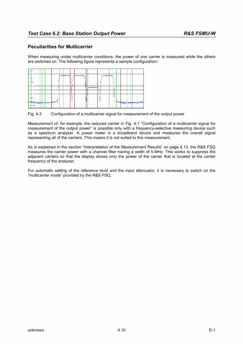
Test Case 6.2: Base Station Output Power R&S FSMU-W
unknown 4.10 E-1
Peculiarities for Multicarrier
When measuring under multicarrier conditions, the power of one carrier is measured while the others are switched on. The following figure represents a sample configuration:
Fig. 4-3 Configuration of a multicarrier signal for measurement of the output power
Measurement of, for example, the reduced carrier in Fig. 4-1 “Configuration of a multicarrier signal for measurement of the output power” is possible only with a frequency-selective measuring device such as a spectrum analyzer. A power meter is a broadband device and measures the overall signal representing all of the carriers. This means it is not suited to this measurement. As is explained in the section “Interpretation of the Measurement Results” on page 4.13, the R&S FSQ measures the carrier power with a channel filter having a width of 5 MHz. This works to suppress the adjacent carriers so that the display shows only the power of the carrier that is located at the center frequency of the analyzer. For automatic setting of the reference level and the input attenuator, it is necessary to switch on the “multicarrier mode” provided by the R&S FSQ.

R&S FSMU-W Test Case 6.2: Base Station Output Power
unknown 4.11 E-1
Structure of the Measurement
The following diagram illustrates the structure of a measurement: Note: The measurement must be made at frequencies B, M and T. This is represented in the
diagram using f={B,M,T}.
Fig. 4-4 Structure of measurement procedure “Base station maximum output power”
Settings on the Base Station
The following table lists the settings to make on the base station: Parameter Value
Output power Maximum power
Test model TM 1
Frequency B, M and T
The other parameters such as the scrambling code, etc can be set to any value. Set the frequency to B, M and T during the course of the measurements.

Test Case 6.2: Base Station Output Power R&S FSMU-W
unknown 4.12 E-1
Steps for Carrying Out a Measurement
1. Set the BS to the basic state Test model 1 Set the frequency, for example, to M Maximum output power Any scrambling code
2. Put the R&S FSQ in the basic state for measurements on 3G base stations See Chapter 3, section “R&S FSQ Basic State for Measurements on 3G Base Stations”. Internal trigger (FREE RUN) Internal reference frequency
3. Set the R&S FSQ to multicarrier mode (opt) Note: Skip this item if there is only one carrier (Single Carrier).
Press the SETTINGS hotkey. The softkeys for configuring the code domain parameters will appear.
Press the NEXT key. The side menu for the settings will open.
Press the MULTI CARR ON OFF softkey. The green marking will switch from OFF to ON, and the R&S FSQ will be in multicarrier mode.
4. Set the power measurement in the R&S FSQ Press the MEAS key.
The softkeys for selecting measurements in spectral mode will appear. Press the POWR softkey.
The power measurement will be performed, and the submenu for the power measurement will appear.
5. Choose the optimum setting for the reference level and input attenuator of the R&S FSQ Press the ADJUST REF LVL softkey.
The R&S FSQ will make a measurement of the power of the base station and will set the reference level and the attenuator to their optimum values.
6. Read off the result The result will be displayed continuously (see the figure below).
Fig. 4-5 Measuring the output power

R&S FSMU-W Test Case 6.2: Base Station Output Power
unknown 4.13 E-1
Interpretation of the Measurement Results
The R&S FSQ measures the carrier power of the RF signals unweighted with a 5 MHz channel filter.
22.0|84.3)1(7.45 =⋅+=≥= αα MHzMHzMHzfBW This works to suppress any adjacent carriers so that the display shows only the power of the carrier that is located at the center frequency of the analyzer. In the result, the frequency correction values set in the R&S FSQ are already taken into account so that the displayed result can be used directly for test evaluation purposes. Triggering
You must set the triggering of the R&S FSQ to FREE RUN. This is done automatically after PRESET. Tips and Special Tricks
Setting the Input Attenuator
Setting of the attenuator is handled automatically after you press the ADUST REF LVL softkey. The input attenuator of the R&S FSQ is set so that the peak value of the input signal to the R&S FSQ’s mixer has a value of less than +5 dBm. Due to the wide dynamic range of the R&S FSQ, the current value of the attenuator is not critical as long as the R&S FSQ is not overdriven. See also Chapter 3, section “Obtaining an Optimum Setting for the R&S FSQ’s Attenuator”. Setting the Reference Level
Setting of the reference level is handled automatically after you press the ADUST REF LVL softkey. The R&S FSQ’s reference level is set so as to just avoid overdriving the instrument, i.e. the reference level is set about 3 dB above the peak value of the signal that is present. Due to the wide dynamic range of the R&S FSQ, the current value of the reference level is not critical as long as the R&S FSQ is not overdriven. See also Chapter 3, section “Obtaining an Optimum Setting for the R&S FSQ’s Reference Level”.
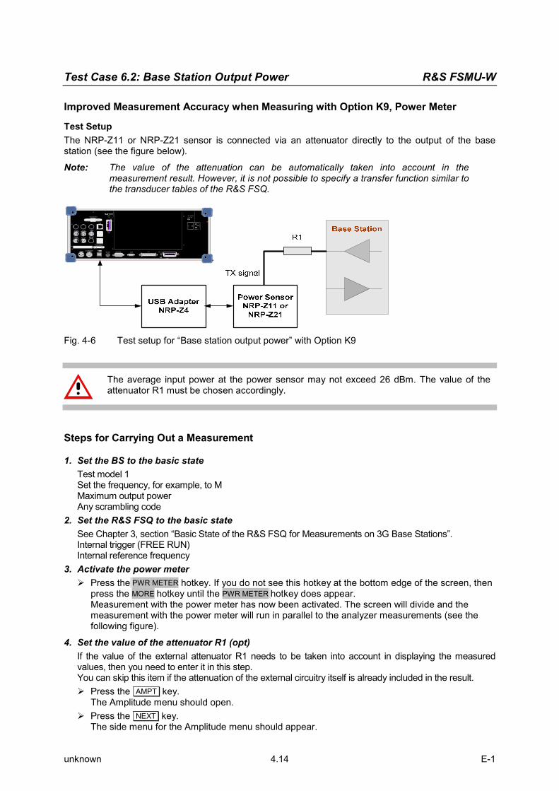
Test Case 6.2: Base Station Output Power R&S FSMU-W
unknown 4.14 E-1
Improved Measurement Accuracy when Measuring with Option K9, Power Meter
Test Setup The NRP-Z11 or NRP-Z21 sensor is connected via an attenuator directly to the output of the base station (see the figure below). Note: The value of the attenuation can be automatically taken into account in the
measurement result. However, it is not possible to specify a transfer function similar to the transducer tables of the R&S FSQ.
SCPI
625 SCP I
I / Q DATA OUT
RE F IN1...20 MHz REF OUT
AUX CONTROL
IEC 2
625SWEEP
EXT TRIGGER/GATE IN MOUSE MONITOR COM LPT
100 - 240 VAC
3.1 - 1.3 A
IEC 2
LAN
REF OUT640 MHz
IF OUT20.4 MHz
IF OUT404.4 MHz
VIDEOOUT
USB
USB
Fig. 4-6 Test setup for “Base station output power” with Option K9
The average input power at the power sensor may not exceed 26 dBm. The value of the attenuator R1 must be chosen accordingly.
Steps for Carrying Out a Measurement
1. Set the BS to the basic state Test model 1 Set the frequency, for example, to M Maximum output power Any scrambling code
2. Set the R&S FSQ to the basic state See Chapter 3, section “Basic State of the R&S FSQ for Measurements on 3G Base Stations”. Internal trigger (FREE RUN) Internal reference frequency
3. Activate the power meter Press the PWR METER hotkey. If you do not see this hotkey at the bottom edge of the screen, then
press the MORE hotkey until the PWR METER hotkey does appear. Measurement with the power meter has now been activated. The screen will divide and the measurement with the power meter will run in parallel to the analyzer measurements (see the following figure).
4. Set the value of the attenuator R1 (opt) If the value of the external attenuator R1 needs to be taken into account in displaying the measured values, then you need to enter it in this step. You can skip this item if the attenuation of the external circuitry itself is already included in the result.
Press the AMPT key. The Amplitude menu should open.
Press the NEXT key. The side menu for the Amplitude menu should appear.

R&S FSMU-W Test Case 6.2: Base Station Output Power
unknown 4.15 E-1
Press the REF LEVEL OFFSET softkey. Use the keypad to enter the desired external attenuation in the input field (e.g. 10) and complete
your entry by pressing the dB key.
5. Set automatic frequency correction of the sensor to the frequency of the base station By entering the working frequency, you can largely eliminate the frequency response error of the sensor.
Press the FREQENCY MANUAL softkey. The Frequency menu should appear.
Use the keypad to enter the desired frequency in the input field (e.g. 2140) and complete your entry by pressing the MHz key. You can enter the frequency in units of GHz, MHz, kHz and Hz.
6. Read off the result The result will be displayed continuously (see Fig. 4-2, Screen display for “Base station output power“ with Option K9).
Fig. 4-3 Screen display for “Base station output power“ with Option K9
Interpretation of the Measurement Results
The power sensor measures the carrier power in a broadband fashion. This means that the total power of all the carriers that are present is measured. If the value of the attenuator R1 is entered in the R&S FSQ, it is incorporated into the result so that the displayed result can be used directly for test evaluation purposes. The result is displayed continuously on the screen.

Test Case 6.2: Base Station Output Power R&S FSMU-W
unknown 4.16 E-1
Sample Program: Measurement with the Analyzer
Note: All of the procedures with a name that begins with “Fsmu_” are described in Chapter 3, section “General Routines”.
/*************************************************************************/ double MeasureBtsPowerWithAnalyzer( int InteractiveMode ) /************************************************************************** * measure the output power using the analyzer's function * parameter: InteractiveMode: true: SMU or BTS needs to be configured * false: just measure * return: power of BTS in dBm **************************************************************************/ { /* ------- change the following variables according to your needs ---- */ /* --------------------- variables ----------------------------------- */ double frequency = 2.14 ; /* GHz */ /* --------------- leave the following variables untouched ---------- */ /* --------------- variables for GPIB bus ---------------------------- */ int analyzer ; /* GPIB handle for analyzer */ char ib_string [1000] ; /* strings written to gpib bus */ /* ---------------------- calculation -------------------------------- */ char result_string [1000] ; /* strings read in from gpib bus */ double result ; /* dBm */ /* ------------------------------------------------------------------- */ /* -------------------- initialize BTS ------------------------------- */ Fsmu_MessageBox ("*** User Info ***", "Set BTS to Test Model 1, Max Power") ; /* -------------------- initialize FSQ ------------------------------- */ Fsmu_InitFsq(&analyzer) ; Fsmu_SetupInstrumentFsq (analyzer) ; /* ----- set the instrument to the frequency of the base station ----- */ sprintf (ib_string, ":SENSe1:FREQuency:CENTer %g GHz", frequency) ; Fsmu_ibWrtln (analyzer, ib_string) ; /* --------------- switch on 3GPP-FDD BTS measurement ---------------- */ /* this sets the instrument to continous sweep implicitely * * wait until operation is completed * * ------------------------------------------------------------------- */ Fsmu_ibWrtln(analyzer, ":INSTrument:SELect WCDPower;*OPC?") ; Fsmu_ibRd (analyzer, ib_string, sizeof (ib_string)) ; /* ------------------ set instrument to single sweep ----------------- */ Fsmu_ibWrtln(analyzer, ":INITiate1:CONTinuous OFF") ; /* ---------------- Single or Multi Carrier mode --------------------- */ if (Fsmu_GetMultiCarrier ()) Fsmu_ibWrtln (analyzer, "CONFigure:WCDPower:BTS:MCARrier:STATe ON") ; else Fsmu_ibWrtln (analyzer, "CONFigure:WCDPower:BTS:MCARrier:STATe OFF"); /* ----------- switch on BTS (max) power measurement ----------------- */ Fsmu_ibWrtln (analyzer, ":CONFigure:WCDPower:BTS:MEASurement POWer") ; /* ---------------- auto adjust the FSQ settings --------------------- */

R&S FSMU-W Test Case 6.2: Base Station Output Power
unknown 4.17 E-1
/* wait for the command execution */ Fsmu_ibWrtln(analyzer, ":SENSe:POWer:ACHannel:PRESet:RLEVel;*OPC?") ; Fsmu_ibRd (analyzer, ib_string, sizeof (ib_string)) ; /* --------- start a single measurement and wait for result ---------- */ Fsmu_ibWrtln (analyzer, "INIT;*OPC?") ; Fsmu_ibRd (analyzer, ib_string, sizeof (ib_string)) ; /* --------------- read in the result, in dBm ------------------------ */ Fsmu_ibWrtln (analyzer, ":CALCulate1:MARKer1:FUNCtion:POWer:RESult? CPOWer") ; Fsmu_ibRdln (analyzer, ib_string, sizeof (ib_string)) ; result = atof (ib_string) ; /* ----------------- display the result ------------------------------ */ sprintf (result_string , "BTS-Maxpower, measured with analyzer: %7.2f dBm", result) ; Fsmu_MessageBox ("*** Result ***", result_string) ; /* --------------------- close FSQ on GPIB --------------------------- */ Fsmu_CloseFsq (analyzer) ; return result ; }

Test Case 6.2: Base Station Output Power R&S FSMU-W
unknown 4.18 E-1
Sample Program: Measurement with Option K9:
Note: All of the procedures with a name that begins with “Fsmu_” are described in Chapter 3, section “General Routines”.
/*************************************************************************/ void MeasureBtsPowerWithK9(void) /************************************************************************** * measure the output power using the analyzer's option K9 (power meter) * **************************************************************************/ { /* -------------------- variables ------------------------------------ */ /* ------ change the following variables according to your needs ----- */ double frequency = 2.14 ; /* GHz */ /* -------------- leave the following variables untouched ----------- */ /* -------------- variables for GPIB bus ----------------------------- */ char ib_string [1000] ; /* strings written to gpib bus */ int analyzer ; /* GPIB handle for Analyzer */ int SaveTimeOut = 0 ; /* saved value of time, when changing * * the device's time out via ibTmo */ /* --------------------- result disply ------------------------------- */ char result_string [1000] ; /* results read in from gpib bus */ double result ; /* dBm */ /* ------------------------------------------------------------------- */ /* ------------------- initialize BTS -------------------------------- */ Fsmu_MessageBox ("*** User Info ***", "Set BTS to Test Model 1, Max Power") ; /* ------------------- initialize FSQ ------------------------------- */ Fsmu_InitFsq(&analyzer) ; Fsmu_SetupInstrumentFsq (analyzer) ; /* ---------- check, if option K9 is installed; exit if not -------- */ Fsmu_ibWrtln(analyzer, "*OPT?") ; Fsmu_ibRd (analyzer, ib_string, sizeof (ib_string)) ; if (strstr (ib_string, ",K9,") == NULL) { Fsmu_MessageBox ("*** Warning ***", "Option K9, Power Meter not installed -- exit"); /* Reset the analyzer */ Fsmu_CloseFsq(analyzer) ; return ; } /* ------------------- switch on power meter ------------------------- */ Fsmu_ibWrtln(analyzer, "SENSe:PMETer:STATe ON") ; /* ------------- set power meter to single measurements -------------- */ Fsmu_ibWrtln(analyzer, "INITiate2:CONTinuous OFF") ; /* ------------ check, if power sensor is installed ----------------- */ /* Query max. frequency; if 0 Hz, * * then the power sensor is not installed * * ------------------------------------------------------------------- */ Fsmu_ibWrtln(analyzer, ":SENSe1:PMETer:FREQuency? max") ; Fsmu_ibRdln (analyzer, ib_string, sizeof (ib_string)) ; if (atoi (ib_string) == 0)

R&S FSMU-W Test Case 6.2: Base Station Output Power
unknown 4.19 E-1
{ Fsmu_MessageBox ("*** Warning ***", "Power sensor seems not to be installed -- exit"); Fsmu_CloseFsq(analyzer) ; return ; } /* ---- Set frequency correction of power meter to BTS frequency ----- */ sprintf (ib_string, ":SENSe1:PMETer:FREQuency %gGHz", frequency) ; Fsmu_ibWrtln(analyzer, ib_string) ; /* ----------- set time out on GPIB bus to sufficient time ----------- */ /* since measurement can take quite a long time * if no signal is applied; set time out to sufficient high value and * save original time out value for later restore */ Fsmu_ibGetTmo(analyzer, &SaveTimeOut) ; Fsmu_ibTmo(analyzer, T100s) ; /* --------- Start a single measurement, and wait for result --------- */ Fsmu_ibWrtln(analyzer, "READ:PMETer?") ; /* -------------------- restore time out value ----------------------- */ Fsmu_ibTmo(analyzer, SaveTimeOut) ; /* ---------------- read in the result; answer in dBm ---------------- */ Fsmu_ibRdln (analyzer, result_string, sizeof (result_string)) ; result = atof (result_string) ; /* ----------------- display the result ----------------------------- */ sprintf (result_string , "BTS-Maxpower, measured with power meter: %7.2f dBm", result) ; Fsmu_MessageBox ("*** Result ***", result_string) ; /* --------------------- close FSQ on GPIB --------------------------- */ Fsmu_CloseFsq(analyzer) ; }

Test Case 6.2.2: CPICH Power Accuracy R&S FSMU-W
unknown 4.20 E-1
Test Case 6.2.2: CPICH Power Accuracy
Test Objective
This test is used to verify whether the base station maintains the power of the primary common pilot channel (CPICH) within specific limits. Quotation from [1]:
CPICH power accuracy is defined as the maximum deviation between the Primary CPICH code domain power indicated on the BCH and the Primary CPICH code domain power measured at the TX antenna interface. The requirement is applicable for all BS types.
Test Setup
The measurement can be performed using the standard test setup (see Chapter 3, section “Standard Test Setup with R&S FSQ”). Only the R&S FSQ is required to perform the measurement: Internal triggering (“FREE RUN”) and the internal reference frequency of the R&S FSQ are sufficient.
Fig. 4-4 Test setup for “CPICH power accuracy”
The input power on the R&S FSQ may not exceed 30 dBm. The value of the attenuator R1 must be chosen accordingly.
Recommended Options
The measurement can be performed without any additional options. Variation in the Parameters of the Base Station
The measurement must be made at the three frequencies B, M and T. Peculiarities for Multicarrier
When measuring under multicarrier conditions, the CPICH power of one carrier is measured while the others are switched on. The following figure represents a sample configuration:

R&S FSMU-W Test Case 6.2.2: CPICH Power Accuracy
unknown 4.21 E-1
Fig. 4-7 Configuration of a multicarrier signal for measurement of the output power
The measurement in the R&S FSQ takes place on the carrier whose frequency the R&S FSQ is set to. For automatic setting of the reference level and the input attenuator, it is necessary to switch on the “multicarrier mode” provided by the R&S FSQ. Structure of the Measurement
The following diagram illustrates the structure of a measurement: Note: The measurement must be made at frequencies B, M and T. This is represented in the
diagram using f={B,M,T}.
Fig. 4-5 Structure of the “CPICH power accuracy” measurement

Test Case 6.2.2: CPICH Power Accuracy R&S FSMU-W
unknown 4.22 E-1
Settings on the Base Station
The following table lists the settings to make on the base station: Parameter Value
Output power Maximum power
Test model TM 2
Frequency B, M and T
Scrambling code Any (but set the same scrambling code on the R&S FSQ)
Antenna diversity OFF
Set the frequency to B, M and T during the course of the measurements. Steps for Carrying Out a Measurement
1. Set the BS to the basic state Test model 2 Set the frequency, for example, to M Maximum output power Set and note the scrambling code Switch off antenna diversity mode
2. Set the R&S FSQ to the basic state See Chapter 3, section “Basic State of the R&S FSQ for Measurements on 3G Base Stations”. We recommend using external triggering to increase the measurement speed, but this is not absolutely necessary. Internal reference frequency The default for the measurement is the channel with code 0, i.e. the CPICH.
3. Set the R&S FSQ to multicarrier mode (opt) Skip this item if there is only one carrier (Single Carrier).
Press the SETTINGS hotkey. The softkeys for configuring the code domain parameters will appear.
Press the NEXT key. The side menu for the settings will open.
Press the MULTI CARR ON OFF softkey. The green marking will switch from OFF to ON, and the R&S FSQ will be in multicarrier mode.
4. Set the scrambling code Press the SETTINGS hotkey.
The softkeys for configuring the code domain parameters will appear. Press the SCRAMBLING CODE softkey.
Enter the scrambling code for the base station as a hexadecimal number. Range of values: 0 to 1FFF. Enter hexadecimal numbers by preceding them with a decimal point. Example: Enter the scrambling code 1F2a by typing 1.52.0
5. Choose the optimum setting for the reference level and input attenuator of the R&S FSQ Press the RESULTS hotkey.
The softkeys for configuring the measurement results in the code domain will appear. Press the ADJUST REF LVL softkey.
The R&S FSQ will make a measurement of the power of the base station and will set the reference level and the attenuator to their optimum values.

R&S FSMU-W Test Case 6.2.2: CPICH Power Accuracy
unknown 4.23 E-1
6. Set the code channel You can skip this item after a reset since the CPICH is always selected after a reset.
Press the RESULTS hotkey. The softkeys for configuring the measurement results in the code domain will appear.
Press the SELECT CHANNEL softkey and enter “0.256” as the channel number. The CPICH is defined as channel code 0; it has a spreading factor of 256 (15 kbit/s).
7. Select the CPICH slot Press the SELECT CPICH SLOT softkey.
The menu for making the settings will appear. Enter the desired CPICH slot. Range of values: 0 to 14; no particular CPICH slot is specified in the standard.
8. Read off the result The result is displayed continuously and can be read off under “Channel Power Abs” in the
Result Summary.
Fig. 4-8 Measuring the CPICH power
Interpretation of the Measurement Results
In addition to other measurement results, the Result Summary shows the absolute power of the selected code channel (marked in red in the upper part of the screen) in the selected CPICH slot. In the result, any specified frequency correction values are already taken into account so that the displayed result can be used directly for test evaluation purposes. The result is displayed continuously on the screen. Tip and Special Tricks
Tips for code domain measurements are described in Chapter 2, “General Settings”.

Test Case 6.2.2: CPICH Power Accuracy R&S FSMU-W
unknown 4.24 E-1
Sample Program
Note: All of the procedures with a name that begins with “Fsmu_” are described in Chapter 2, section “General Routines”.
/*************************************************************************/ void MeasureCpichPowerAccuracy (void) /************************************************************************* * measure the Accuracy of CPICH power *************************************************************************/ { /* -------------------- variables ------------------------------------ */ /* ------ change the following variables according to your needs ----- */ double frequency = 2.14 ; /* GHz */ int scrambling_code = 0x0 ; /* scrambling code in hex */ /* -------------- leave the following variables untouched ----------- */ /* -------------- variables for GPIB bus ----------------------------- */ char ib_string [1000] ; /* strings written to gpib bus */ int analyzer ; /* GPIB handle for Analyzer */ int status ; /* of service register */ /* ----------------- calculation and result display ------------------ */ char result_string [1000] ; /* strings read in from gpib bus */ Fsq_ResultSummary result_summary ; /* structure of the results */ int length_of_data ; /* in Bytes */ /* ------------------------------------------------------------------- */ /* ------------------- initialize BTS -------------------------------- */ Fsmu_MessageBox ("*** User Info ***", "Set BTS to Test Model 2, Max Power") ; /* ------------------- initialize FSQ -------------------------------- */ Fsmu_InitFsq(&analyzer) ; Fsmu_SetupInstrumentFsq (analyzer) ; /* ---- Set the instrument to the frequency of the base station ------ */ sprintf (ib_string, ":SENSe1:FREQuency:CENTer %g GHZ", frequency) ; Fsmu_ibWrtln (analyzer, ib_string) ; /* ----- Switch on 3GPP-FDD BTS measurement -------------------------- */ /* this sets the instrument to continous sweep implicitely * * ------------------------------------------------------------------- */ Fsmu_ibWrtln(analyzer, "INSTrument:SELect BWCD") ; /* ------------- set instrument to single sweep ---------------------- */ Fsmu_ibWrtln(analyzer, ":INITiate1:CONTinuous OFF") ; /* --- set instrument to external trigger (opt), offset -100 usec ---- */ /* set trigger to external after switch on code domain power * * measurement, as negative trigger offsets are only allowed in * * zero span */ Fsmu_ibWrtln(analyzer, ":TRIGger1:SEQuence:SOURce EXTernal") ; Fsmu_ibWrtln(analyzer, ":TRIGger:SEQuence:HOLDoff -100us"); /* ----------- Set FSQ to Single or Multi Carrier mode --------------- */ if (Fsmu_GetMultiCarrier ()) Fsmu_ibWrtln (analyzer, "CONFigure:WCDPower:BTS:MCARrier:STATe ON") ; else Fsmu_ibWrtln (analyzer, "CONFigure:WCDPower:BTS:MCARrier:STATe OFF");

R&S FSMU-W Test Case 6.2.2: CPICH Power Accuracy
unknown 4.25 E-1
/* ------------ set FSQ to code domain power measurement ------------- */ Fsmu_ibWrtln(analyzer, "CONFigure:WCDPower:MEASurement WCDPower") ; /* ------------------------- set scrambling code --------------------- */ /* %1x prints an integer in hex at least one digit */ sprintf (ib_string, ":SENSe:CDPower:LCODe:VALue #H%1x", scrambling_code) ; Fsmu_ibWrtln(analyzer, ib_string) ; /* ----------------- use auto detection of test model --------------- */ /* (best results in most cases) * * + alternatively: use predefined test model 2 * * Fsmu_ibWrtln(analyzer, ":CONFigure:WCDPower:BTS:CTABle:STATe ON") ; * * Fsmu_ibWrtln(analyzer, * ":CONFigure:WCDPower:BTS:CTABle:SELECT '3GB_2'") ; * */ Fsmu_ibWrtln(analyzer, ":CONFigure:WCDPower:BTS:CTABle:STATe OFF") ; /* --------------------- switch off antenna diversity ---------------- */ Fsmu_ibWrtln(analyzer, ":SENSe:CDPower:ANTenna OFF") ; /* ------------- select CPICH = code 0, spreading factor 256 --------- */ Fsmu_ibWrtln(analyzer, ":SENSe:CDPower:CODE 0") ; /* -------- select any slot between 0 and 14 here: 14 ---------------- */ Fsmu_ibWrtln(analyzer, ":SENSe:CDPower:SLOT 14") ; /* ----------switch FSQ into code domain power measurement------------ */ Fsmu_ibWrtln(analyzer, ":CALCulate2:FEED 'XTIM:CDP:ERR:SUMMary'") ; /* --------- perform an auto adjust the FSQ settings ----------------- */ /* wait for the command execution * * this needs the external trigger being active too */ Fsmu_ibWrtln(analyzer, ":SENSe:POWer:ACHannel:PRESet:RLEVel;*OPC?") ; Fsmu_ibRd (analyzer, ib_string, sizeof (ib_string)) ; /* ----------------- clear status registers -------------------------- */ Fsmu_ibWrtln (analyzer, "*CLS") ; /* --------- wait for next external trigger and for result ----------- */ Fsmu_ibWrtln (analyzer, "INITiate:IMMediate;*OPC?") ; Fsmu_ibRd (analyzer, ib_string, sizeof (ib_string)) ; /* ---------- status questionable register, indicates sync ----------- */ Fsmu_ibWrtln (analyzer, ":STATus:QUEStionable:SYNC:CONDition?") ; Fsmu_ibRdln (analyzer, ib_string, sizeof (ib_string)) ; status = atoi (ib_string) ; /* ---------------------- NO SYNC if 2nd bit is set ------------------ */ if (status & 0x02) { Fsmu_MessageBox ("*** ERROR ***", "Sync FAILED -- abort") ; Fsmu_CloseFsq (analyzer) ; return ; } /* ----------------------- read in the summary result ---------------- */ /* see evm.c for a detailled information on reading in the result in * other format

Test Case 6.2.2: CPICH Power Accuracy R&S FSMU-W
unknown 4.26 E-1
*/ Fsmu_ibWrtln (analyzer, ":FORMat REAL,32;:TRACe:DATA? Trace2") ; /* --------------------- read in '#d' ------------------------------- */ Fsmu_ibRd (analyzer, ib_string, 2) ; /* ----------------- skip the '#', get length of next field --------- */ length_of_data = ib_string [1] - '0' ; /* ----------------- read in 'lll'; length -------------------------- */ Fsmu_ibRd (analyzer, ib_string, length_of_data) ; ib_string [length_of_data] = '\0' ; length_of_data = atoi (ib_string) ; /* -------------------------- read in the data ----------------------- */ Fsmu_ibRd (analyzer, (char *)&result_summary, length_of_data) ; /* ---------------- read in trailing LF from FSQ -------------------- */ Fsmu_ibRd (analyzer, ib_string, 1) ; /* ----------------- Display the result ------------------------------ */ sprintf (result_string , "Absolute channel power (CPICH): %9.2f dBm", result_summary.power_abs_channel) ; Fsmu_MessageBox ("*** Result ***", result_string) ; /* --------------------- Reset the analyzer ------------------------- */ Fsmu_CloseFsq (analyzer) ; }

R&S FSMU-W Test Case 6.3: Frequency Error
unknown 4.27 E-1
Test Case 6.3: Frequency Error
Test Objective
This test case is used to verify whether the frequency errors of the base station lie within certain limits. The test involves measurements at the maximum and minimum power of the base station. If the base station supports “Closed Loop Diversity” [4] or “Space Time Transmit Diversity” (STTD, [4]), then the test should be performed on both of the antennas. Quotation from [1]:
Frequency error is the measure of the difference between the actual BS transmit frequency and the assigned frequency. The same source shall be used for RF frequency and data clock generation.
Test Setup
As the test of frequency error is performed in connection with test case 6.7.1, Error Vector Magnitude, the description of the test setup and all of the recommended options can be found within the chapter of test case 6.7.1. See chapter 6.7.1 for further details.

Test Case 6.4.2: Power Control Steps R&S FSMU-W
unknown 4.28 E-1
Test Case 6.4.2: Power Control Steps
Test Objective
If we want to make the best possible usage of the base station’s transmission capacity, it is necessary to optimize the transmitted power for each individual UE. On the one hand, the transmitted channel power should be as low as possible since this power increases the noise for all of the other UEs. On the other hand, the transmitted power needs to be high enough to ensure satisfactory transmission for the UE. For use in optimizing the transmitted power, the standard defines a control system for the base station’s transmitted power for each channel. This is known as the “inner control loop” and its functioning is checked as part of this test. This test is used to verify whether the base station can vary the power of a channel in the code domain within certain limits.
Fig. 4-9 “Power control on the downlink“
Basic principle of the control loop: The UE evaluates the signal quality in each timeslot and then requests that the transmit level of the BS be increased or decreased accordingly. This request is transmitted using the transmit power control bits (TPC) sent by the UE in the dedicated physical control channel (DPCCH) in the uplink channel. Based on the received TPC bits, the base station adjusts the power in the channel by exactly one power level up or down as needed (either 1.0 dB or 0.5 dB depending on the standard). This test checks to see whether the magnitude of each individual power step ranges within certain limits starting from each possible power step. The cumulative power change as a result of ten successive (identical) TPC bits is also checked. Quotation from [1]:
The power control step is the required step change in the code domain power of a code channel in response to the corresponding power control command. The combined output power change is the required total change in the DL transmitter output power of a code channel in response to multiple consecutive power control commands corresponding to that code channel.

R&S FSMU-W Test Case 6.4.2: Power Control Steps
unknown 4.29 E-1
Inner loop power control in the downlink is the ability of the BS transmitter to adjust the transmitter output power of a code channel in accordance with the corresponding TPC symbols received in the uplink. The power control step is the required step change in the DL transmitter output power of a code channel in response to the corresponding power control command. The combined output power change is the required total change in the DL transmitter output power of a code channel in response to multiple consecutive power control commands corresponding to that code channel. The power control dynamic range is the difference between the maximum and the minimum code domain power of a code channel for a specified reference condition. Transmit modulation quality shall be maintained within the whole dynamic range as specified in TS 25.104 [1] subclause 6.8.
Down link (DL) power control dynamic range: - maximum code domain power: BS maximum output power -3 dB or greater; - minimum code domain power: BS maximum output power -28 dB or less. The normative reference for this requirement is TS 25.104 [1] subclause 6.4.2.1.
Performing the Test
During the test, the SMU replaces the UE. The R&S SMU transmits a precisely defined TPC bit sequence in the uplink channel. The base station responds by controlling the transmitted power of the data channel (which is checked by the R&S FSQ). Two different scenarios are tested. To measure the “aggregated power”, the power of the channel is set starting from Pmax – 3dB to Pmin and then back to Pmax – 3dB. See Fig. 4-10, Plot of the code domain power in the “aggregated power control steps”. Pmin is less than or equal to Pmax – 28 dB, meaning a dynamic range of at least 25 dB is required. Test model 2 sets the channel (120; 30 ksps) to a power level of Pmax – 3 dB and thus represents the starting position for the measurement. The R&S SMU then sends a number of TPC bits with a value of “0” corresponding to the number of power steps the base station has. Then, the same number of TPC bits with a value of “1” is transmitted so that the power of the channel being tested is again equal to Pmax – 3 dB. The standard requires measurement of the cumulative power differences of the falling and rising edge in the respective upper and lower power range. To be able to perform this test in a single measurement, it is necessary to record more than one frame. For a stepsize of 0.5 dB and a dynamic range of 25 dB, at least 100 timeslots must be recorded (corresponding to 7 frames). Using the R&S FSQ’s multiframe function, the frames required for this purpose can be recorded without any gaps and then be analyzed. To ensure that the base station responds reliably to the TPC bits from the R&S SMU, some frames with TPC bits = “1” are transmitted at the start of the test (“preamble”). This keeps the power of the base station at the maximum level in the channel being tested. Once the preamble is complete, the R&S FSQ is triggered using marker 1 of the R&S SMU and the actual recording of the measurement data begins.

Test Case 6.4.2: Power Control Steps R&S FSMU-W
unknown 4.30 E-1
Fig. 4-10 Plot of the code domain power in the “alternating power control steps
When measuring the “alternating power”, a sequence of “0101” is sent for each power step and the related power levels are measured. The standard does not say how many 01 sequences are to be sent per power step. The TPC pattern is best set so that per frame exactly one power step is tested. Thus, a TPC pattern per frame of “0101 0101 0101 010” is selected, i.e. There is one more “0” in the pattern than there are “1”s. The recording goes on until all of the power steps have been determined. Fig. 4-10, Plot of the code domain power in the “aggregated power control steps” test shows the code domain power vs. time (timeslots) for this case. For a dynamic range of 25 dB, this means that at least 25 or 50 frames are needed depending on whether the power steps are 0.5 dB or 1.0 dB. For evaluation purposes, it is best to shift the start of a new sequence to the frame limit in each case. This allows you to see the maximum and minimum steps per power step at a glance using the R&S FSQ. To ensure that the base station responds reliably to the TPC bits from the R&S SMU, some frames with TPC bits = “1” are transmitted at the start of the test (“preamble”). This keeps the power of the base station at the maximum level in the channel being tested. Once the preamble is complete, the R&S FSQ is triggered using marker 1 of the R&S SMU and the actual recording of the measurement data begins. By shifting the marker within a frame, you can ensure that the measurement starts at the frame limit for each power step. Using the R&S FSQ’s multiframe function, the frames required for this purpose can be recorded without any gaps up to a length of 100 frames and then analyzed. The R&S SMU reads in the data from a list and generates the output in real time. This means it has no limitations with regard to the memory depth.
Fig. 4-11 Plot of the code domain power in the “alternating power control steps” test

R&S FSMU-W Test Case 6.4.2: Power Control Steps
unknown 4.31 E-1
Test Setup
This test requires the R&S SMU as well as the R&S FSQ. The base station transmit the downlink signal and determines the timing. The frame trigger of the base station triggers the R&S SMU via the “Trigger 1” input. The R&S SMU simulates a UE and sends the necessary TPC bits in the uplink in the control channel. The trigger input of the R&S SMU remains disabled until a complete TPC bit sequence has passed. The R&S SMU outputs the start signal for the R&S FSQ on the “Marker 1” output. The R&S FSQ receives it via the “EXT Trigger / GATE IN”.Fig. 4-2 shows the test setup. Connect R&S SMU, “Marker 1” to the R&S FSQ, EXT Trigger / GATE IN using a BNC cable. Connect the base station trigger output “Frame Trigger” to the R&S SMU “Trigger 1”.
Fig. 4-12 Test setup for “Power control steps”
The input power on the R&S FSQ may not exceed 30 dBm. The value of the attenuator R1 must be chosen accordingly.
Recommended Options
The measurement can be performed without any additional options.

Test Case 6.4.2: Power Control Steps R&S FSMU-W
unknown 4.32 E-1
Test Case Wizard Panel
The Fig. 4-13 and Fig. 4-14 show the input parameters for both kinds of Edit Modes ‘According to Standard’ and ‘User Definable’.
Fig. 4-13 Test case panel for ‘According to Standard’

R&S FSMU-W Test Case 6.4.2: Power Control Steps
unknown 4.33 E-1
Fig. 4-14 Test case panel for ‘User Definable’
The input/ouput parameters of the wizard panel read as follows: Wanted Signal State Enables/Disables the signal generation of the wanted 3GPP signal. In
case of ‘According to Standard’ the state is fixed to ‘On’. In case of ‘User Definable’ the user may switch ‘Off’ the state. Remote-control command: :SOUR:BB:W3GP:TS25141:WSIGnal:STATe [ON | OFF]
RF Frequency Sets the RF frequency of the wanted signal. Remote-control command: :SOUR:BB:W3GP:TS25141:WSIGnal:FREQ [100.0 KHz .. 6.0 GHz]
Power Level (read only in case of ‚According to Standard’)
Displays the RF power level of the wanted signal in case of ‘According to Standard’: • -120.3 + 10 dBm when Wide Area BS • -110.3 + 10 dBm when Medium Range BS • -106.3 + 10 dBm when Local Area BS In case of ‘User Definable’ the user can enter an arbitrary power level figure. Remote-control command: :SOUR:BB:W3GP:TS25141:WSIGnal:POW [-145.0 dBm .. 20.0 dBm]
Slot Format DPCCH # Sets the slot format. Slot formats 0 to 5 are available for the DPCCH channel. The slot format defines the FBI mode and the TFCI status. The user can choose from: • 0: no FBI field / TFCI on • 1: no FBI field / TFCI off

Test Case 6.4.2: Power Control Steps R&S FSMU-W
unknown 4.34 E-1
• 2: 1 FBI field / TFCI on • 3: 1 FBI field / TFCI off • 4: 2 FBI field / TFCI off • 5: 2 FBI field / TFCI on Remote-control command: :SOUR:BB:W3GP:TS25141:WSIGnal:DPCCh:SFORmat [0..5]
Overall Symbol Rate DPDCH
Sets the overall symbol rate of all the DPDCH channels. The structure of the DPDCH channel table depends on this parameter. The user can select from: • 15 ksps • 30 ksps • 60 ksps • 120 ksps • 240 ksps • 480 ksps • 960 ksps • 2 x 960 ksps • 3 x 960 ksps • 4 x 960 ksps • 5 x 960 ksps • 6 x 960 ksps Remote-control command: :SOUR:BB:W3GP:TS25141:WSIGnal:DPDCh:ORATe [D15K | D30K | D60K | D120k | D240k | D480k | D960k | D1920k | D2880k | D3840k | D4800k | D5760k]
Power Ratio DPCCH/DPDCH
Sets the channel power ratio of DPCCH versus DPDCH. Remote-control command: :SOUR:BB:W3GP:TS25141:WSIGnal:DCRatio
Propagation Delay Sets an additional propagation delay besides the fixed DL-UL timing offset of 1024 chip periods. Note: The additional propagation delay is achieved by charging
the start trigger impulse with the respective delay . Remote-control command: :SOUR:BB:W3GP:TS25141:WSIGnal:TRIGger[:EXTernal]:DELay
TPC Start Pattern Sets the controling TPC pattern for initialisation of the base stations power level. The TPC Start pattern is sent before the TPC repeat pattern. The user can select from • Maximum Power Less n Steps: A continuously sent ‘power up’
command will force the base station to maximum power, by n ‘power down’ commands the base station will finally start n power steps (e.g. 1 dB or 0.5 dB) below its maximum transmit power.
• Data List (if ‘User Definable’): After selecting the data list item a box opens on the right side to enter an arbitrary power control pattern stored in the R&S SMU data list format, that will be sent before the periodical TPC Repeat Pattern.
Remote-control command: :SOUR:BB:W3GP:TS25141:WSIGnal:DPCCh:TPC:SDATa [PMAX | DLISt] If ‘Data List’ is selected input also the data list name: :SOUR:BB:W3GP:TS25141:WSIGnal:DPCCh:TPC:SDATa:DSELect FileName

R&S FSMU-W Test Case 6.4.2: Power Control Steps
unknown 4.35 E-1
Power Up Steps (when ‚Maximum Power Less n Steps’ is selected)
Sets the number of ‘power up’ commands (‘1’) in the TPC start pattern. The total TPC start pattern length is the number of ‘power up’ commands plus the entered number of n ‘power down’ (‘0’) steps. Remote-control command: :SOUR:BB:W3GP:TS25141:WSIGnal:DPCCh:TPC:SDATa:PUSTeps [0..1000]
Power Down Steps (when ‚Maximum Power Less n Steps’ is selected)
Sets the number of ‘power down’ commands (‘0’) in the TPC start pattern. The total TPC start pattern length is the number of ‘power up’ commands plus the entered number of n ‘power down’ (‘0’) steps. Remote-control command: :SOUR:BB:W3GP:TS25141:WSIGnal:DPCCh:TPC:SDATa:PDSTeps [0..1000]
TPC Repeat Pattern Sets the controling TPC pattern for verification of the base stations power control steps. The user can select from • Single Power Steps (01 pattern): A 01 pattern is sent periodically
for measurement of the transmitter power control step tolerance • Aggregated Power Steps (00000000001111111111): A
00000000001111111111 pattern is sent periodically for measurement of the transmitter aggregated power control step range after 10 consecutive equal commands
• Maximum Power (All 1) (if ‘User Definable’): A continuously sent ‘power up’ command will force the base station to maximum power
• Minimum Power (All 0) (if ‘User Definable’): A continuously sent ‘power down’ command will force the base station to minimum power
• Pattern (if ‘User Definable’): After selecting the pattern item a box opens on the right side to enter an arbitrary power control pattern, that will be sent periodically.
• Data List (if ‘User Definable’): After selecting the data list item a box opens on the right side to enter an arbitrary power control pattern stored in the R&S SMU data list format, that will be sent periodically.
In case of ‘According to Standard’ the items ‘Maximum Power’, ‘Minimum Power’ and ‘Pattern’ are disabled. Remote-control command: :SOUR:BB:W3GP:TS25141:WSIGnal:DPCCh:TPC:RDATa [SINGle | AGGRegated | ONE | ZERO | PATTern | DLISt] If ‘Pattern’ is selected input also the pattern: :SOUR:BB:W3GP:TS25141:WSIGnal:DPCCh:TPC:RDATa:PATTern [#H0 .. #HFFFF FFFF FFFF FFFF, PatternLength] If ‘Data List’ is selected input also the data list name: :SOUR:BB:W3GP:TS25141:WSIGnal:DPCCh:TPC:RDATa:DSELect FileName
In case of Marker Configuration ‘Auto’ the Marker1 starts delayed by the TPC start pattern length. A slot taking 0.625 ms consists of 2560 chips, where depending on the slot format 1 or 2 TPC bits are sent.
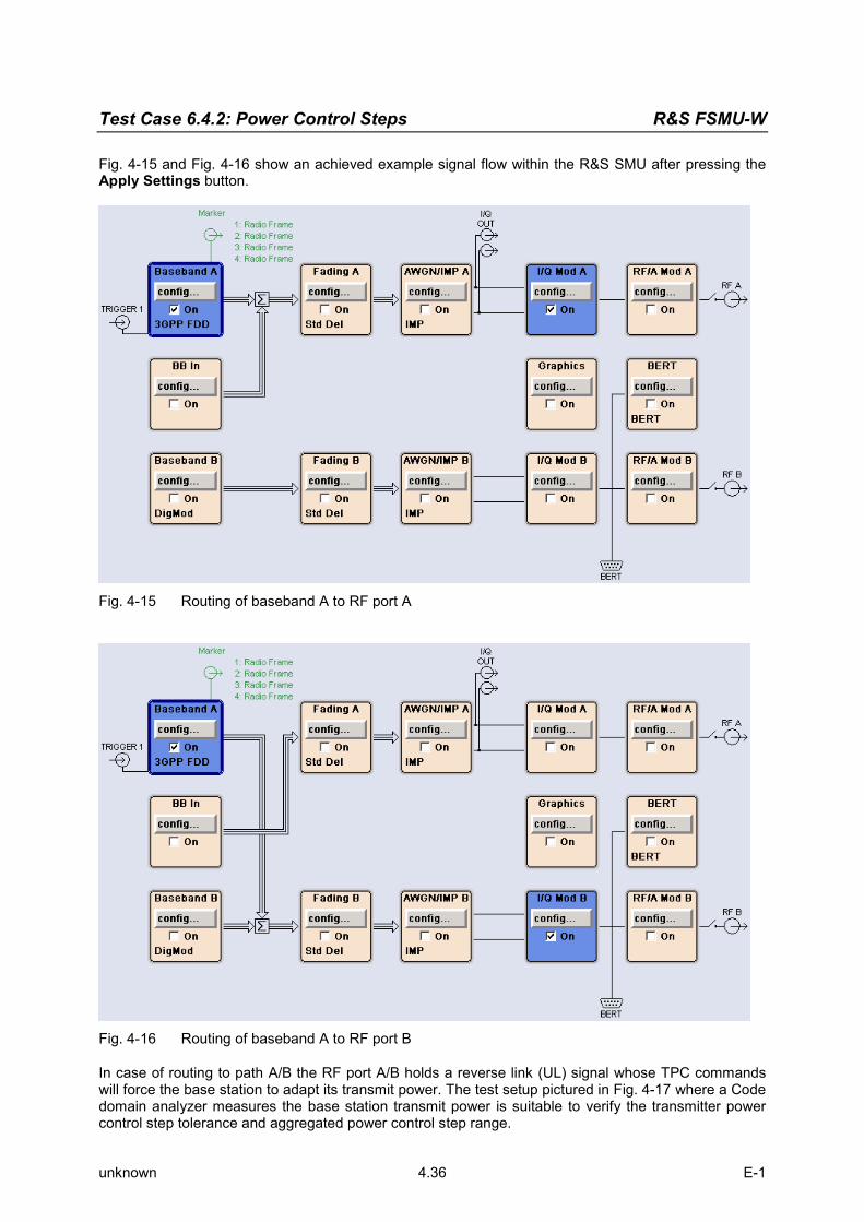
Test Case 6.4.2: Power Control Steps R&S FSMU-W
unknown 4.36 E-1
Fig. 4-15 and Fig. 4-16 show an achieved example signal flow within the R&S SMU after pressing the Apply Settings button.
Fig. 4-15 Routing of baseband A to RF port A
Fig. 4-16 Routing of baseband A to RF port B
In case of routing to path A/B the RF port A/B holds a reverse link (UL) signal whose TPC commands will force the base station to adapt its transmit power. The test setup pictured in Fig. 4-17 where a Code domain analyzer measures the base station transmit power is suitable to verify the transmitter power control step tolerance and aggregated power control step range.

R&S FSMU-W Test Case 6.4.2: Power Control Steps
unknown 4.37 E-1
UL signal generator
(Psudo UE)
Base Station
Under Test
Attenuator
Code domain
analyser
Rx
Tx
Fig. 4-17 Test Setup according to TS 25.141 for Baseband A Signal Routing to RF Port A
Variation in the Parameters of the Base Station
Test model 2 is used for the measurement. The measurement must be made at the three frequencies B, M and T. The base station must respond with the channel (120; 30 ksps) to the TPC bits of the R&S SMU. Peculiarities for Multicarrier
When measuring under multicarrier conditions, the total power and the code channel power of one carrier are measured while the others are switched on. The following figure represents a sample configuration:
Fig. 4-18 “Configuration of a multicarrier signal for measurement of the dynamic range of the
channel power” The measurement in the R&S FSQ takes place on the carrier whose frequency the R&S FSQ is set to. For automatic setting of the reference level and the input attenuator, it is necessary to switch on the “multicarrier mode” provided by the R&S FSQ.

Test Case 6.4.2: Power Control Steps R&S FSMU-W
unknown 4.38 E-1
Structure of the Measurement
The structure of the measurement procedure shown in the following diagram is optimized for minimum run time: A change of frequency is faster than reloading the ARB in the R&S SMU. This works in the inner look over frequency. Note: The measurement must be made at frequencies B, M and T. This is represented in the
diagram using f={B,M,T}.
Fig. 4-19 Structure of the “Power Control Steps“ measurement
Settings on the Base Station
The following table lists the settings to make on the base station: Parameter Value
Output power Maximum power
Test model TM 2
Power in channel 120 Pmax – 3 dB (corresponds to TM 2)
Frequency B, M and T
Scrambling code Any (but set the same scrambling code on the R&S FSQ)
Antenna diversity OFF
You should set test model 2. The absolute power of the channel (120; 30 ksps) is reduced from (Pmax – 3 dB) to (Pmax – 28 dB). The base station should respond to the TPC bits of the R&S SMU. Set the frequency to B, M and T during the course of the measurements.

R&S FSMU-W Test Case 6.4.2: Power Control Steps
unknown 4.39 E-1
Steps for Carrying Out a Measurement
The measurement must be performed separately for “aggregated power control steps” and “alternating power control steps”. In the following description, the “aggregated power control steps” are measured first and then the “alternating power control steps”. The instrument settings are transferred for the most part. For simulating the UE, the UE1 of the R&S SMU is used in the example. The R&S SMU’s UE1 can generate the data in real time and thus produce patterns of any length. Aggregated Power Steps
The TPC sequence is entered directly into the UE1 as a “Pattern”. This is possible for sequences having a maximum length of 64 bits. BS
Set the BS to the basic state Test model 2 Set the frequency, for example, to M Maximum output power Set and note the scrambling code Switch off antenna diversity mode Channel (120; 30 ksps) must respond to the R&S SMU
R&S FSQ
1. Set the R&S FSQ to the basic state See Chapter 3, section “Basic State of the R&S FSQ for Measurements on 3G Base Stations”. For automatic setting of the reference level, deactivate the external trigger, then switch it back on. Internal reference frequency
2. Set the R&S FSQ to multicarrier mode (opt) Skip this item if there is only one carrier (Single Carrier).
Press the SETTINGS hotkey. The softkeys for configuring the code domain parameters will appear.
Press the NEXT key. The side menu for the settings will open.
Press the MULTI CARR ON OFF softkey. The green marking will switch from OFF to ON, and the R&S FSQ will be in multicarrier mode.
3. Set the scrambling code Press the SETTINGS hotkey.
The softkeys for configuring the code domain parameters will appear. Press the SCRAMBLING CODE softkey.
Enter the scrambling code for the base station as a hexadecimal number. Range of values: 0 to 1FFF Enter hexadecimal numbers by preceding them with a decimal point. Example: Enter the scrambling code 1F2a by typing 1.52.0
4. Choose the optimum setting for the reference level and input attenuator of the R&S FSQ Press the RESULTS hotkey.
The softkeys for configuring the measurement results in the code domain will appear. Press the ADJUST REF LVL softkey.
The R&S FSQ will make a measurement of the power of the base station and will set the reference level and the attenuator to their optimum values.
5. Set the trigger to external Press the TRIG hotkey.

Test Case 6.4.2: Power Control Steps R&S FSMU-W
unknown 4.40 E-1
The softkeys for configuring the trigger will appear. Press the EXTERN softkey.
This will set the R&S FSQ for external triggering. Press the TRIGGER OFFSET optional softkey.
Enter the desired trigger offset with the desired unit in the input field using the keypad.
6. Set the channel (120; 30 ksps) Press the RESULTS hotkey.
The softkeys for configuring the measurement results in the code domain will appear. Press the SELECT CHANNEL softkey and enter “120,128” as the channel number.
The channel at the far right on the screen will be marked in red.
7. Choose multiframe mode Press the SETTINGS hotkey.
The softkeys for configuring the code domain parameters will appear. Press the NEXT key.
The side menu for the settings will open. Press the MULTI FRM CAPTURE softkey.
The softkeys for configuring the multiframe measurement will appear. Press the CAPTURE LENGTH softkey.
Enter the desired number of frames in the input field using the keypad.
8. Select Single Sweep and prepare the R&S FSQ for the measurement Press the SWEEP key.
The side menu for the settings will open. Press the MSINGLE SWEEP softkey.
This will set the R&S FSQ for a single sweep so it is waiting for a trigger. To restart a measurement, press the CONTINUE SGL SWEEP softkey.
The softkey will be colored in green and the R&S FSQ will wait for the next trigger. Press the CAPTURE LENGTH softkey.
Enter the desired number of frames in the input field using the keypad. R&S SMU
1. Set the R&S SMU to the basic state. See Chapter 3, section “R&S SMU basic state for measurements on 3G base stations”. You are in the menu for configuring a 3GPP FDD measurement.
2. Set the output power level Press the LEVEL key.
Set the desired output power in the input field. Use ESC to exit the input mode.
3. Select the test model Select the link direction. Set link direction to Uplink / Reverse and complete your entry with ENTER . Select the Test Setup / Models menu.
The menu for selecting the test models will appear. Select the desired model, e.g. TDPCCH_DPDCH_60 ksps and complete your entry with ENTER .
4. Set TPC bits for Aggregated Select the UE1 menu.
The menu for configuring User Equipment 1 should appear. Select Pattern in the TPC Data Source menu.
The menu for entering the TPC pattern will appear. Select TPC Pattern.
In the input field, enter 01 and as many zeroes as are necessary (depending on how many dynamic steps the base station supports). See "Tips and Special Tricks“, page 4.47 for

R&S FSMU-W Test Case 6.4.2: Power Control Steps
unknown 4.41 E-1
information about selecting a suitable pattern. In Read Out Mode, select Single + All 1. This causes the power of the channel with code number 120
to first be reduced by x steps. It is then raised back to the maximum power level.
5. Set the scrambling code Select the Scrambling Copde (hex) menu.
Enter the desired scrambling code as a hexadecimal number in the input field. Press the ESC key.
The menu for configuring a 3GPP FDD measurement will appear again.
6. Set the length of the generated pattern Select Filter/Clipping/ARB Setting. Select Sequence Length.
Select the desired number of frames. For a base station with a 25 dB dynamic range and 0.5 dB level steps, you will need to set 25*2*2 / 15 = 6.7, i.e. 7 frames.
Press the ESC key. The basic configuration menu will appear again.
7. Set the trigger The trigger is set to the external source (Trigger 1) so that the R&S SMU is triggered by the BS. To ensure that the selected pattern is not interrupted by a newer trigger, the trigger is disabled during the period duration by specifying “External Inhibit”. The R&S FSQ is triggered by Marker 1.
Select Trigger/Marker… Select Mode Armed Retrigger.
This causes the TPC sequence to be started with the external trigger event. It is restarted for each external trigger event.
Select the source External, (TRIGGER 1) in the Source menu. The menus for configuring the external trigger should appear.
In the External Inhibit menu, enter the length in chips as was computed in the previous step (number of chips = numbers of frames * 38400). This makes it possible to generate a signal with a longer duration than is specified by the frame trigger.
Press the ESC key. The basic configuration menu will appear again.
8. Set the marker The measurement by the R&S FSQ is initiated by the R&S SMU with Marker 1. To enable continuous measurement, the period of the marker generation is set to the length of the pattern. The marker is handled as follows:
Select Trigger/Marker… Select Mode Armed Retrigger.
This causes the TPC sequence to be started with the external trigger event. It is restarted for each external trigger event.
Select Marker 1 in the Marker Mode field. Set it to User Period. The menu for entering the period duration should appear.
Select the Period menu and set the same number of frames as was computed in step 15. Press the ESC key.
The basic configuration menu will appear again.
9. Switch on RF generation Press the RF ON/OFF key.
The RF output of the R&S SMU will be switched on. The color of the RF/A-Mod block will change to blue and a check will appear next to ON.
10. Switch on baseband generation Select State.
The signal will be computed and OFF will change to ON.

Test Case 6.4.2: Power Control Steps R&S FSMU-W
unknown 4.42 E-1
Alternatively, the steps to construct the desired signal can be carried out via the test case wizard: Set the test case wizard
Press Test Case and select Test Case 6.4.2. The panel adapts to its test case.
Press Edit Mode and select According to Standard. This selection guides the user close to TS 25.141.
Press Trigger Configuration and select Auto. This selection applies to this measurement description.
Press Marker Configuration and select Auto. This selection applies to this measurement description.
Press Baseband A Signal Routing and select which RF output port (A or B) is connected to the BS. Enter Scrambling Code, Scrambling Mode according to the BS scrambling scheme. Enter the Power Class of the BS under test. Press RF Frequency and enter the same frequency (e.g. M) the BS has set to. Enter the Slot Format DPCCH # of the UL signal. Enter the Overall Symbol Rate DPDCH. Enter the Power Ratio DPCCH/DPDCH. Enter the Propagation Delay. Enter the TPC Start Pattern. Enter the number of Power Up Steps and Power Down Steps in case of ‘Maximum Power Less n
Steps’ is previously selected. Enter the TPC Repeat Pattern. Press Apply Settings.
The R&S SMU is now ready to start signal generation. Base station
Set the frequency of the base station and activate the base station Read off the result on the R&S FSQ
1. Set the desired result presentation and reference level on the screen Press the RESULTS hotkey.
The menu for the various evaluation types will appear. Press the POWER VS SLOT softkey.
A barchart will appear on screen B showing the power of the individual slots. Press the SCREEN B hotkey.
Screen B will be activated and the labelling of the hotkey will change to “SCREEN B”. All this step does is improve the display. It has no influence on the evaluation of the measurement.
Press the REF VALUE POSITION softkey. Use the Rotary knob to set the reference position to the optimum value (approx. 50%).
2. Read off the level for all of the power steps of interest Press the MARKER softkey.
Use the Rotary knob to move the marker to the desired CPICH slot (see figure). Read off the value from the marker field.
3. Change the frame Press the SETTINGS hotkey.
The softkeys for configuring the code domain parameters will appear. Press the NEXT hardkey.
The side menu for further input of the settings will appear.

R&S FSMU-W Test Case 6.4.2: Power Control Steps
unknown 4.43 E-1
Press the MULTI FRM CAPTURE softkey. The submenu for multiframes will appear.
Press the FRAME TO ANALYZE softkey. Enter the desired frame in the input field and confirm your input with ENTER .
Fig. 4-20 Measurement of the “aggregated power control steps”
4. Frames and slots required for a standard base station For a base station with 1 dB steps and 25 dynamic power steps, the power levels need to be
evaluated for the following frame / slot values: Frame Slot Value
0 2 Maximum
0 12 Maximum – 10
1 2 Minimum + 10
1 12 Minimum
TPC command “0” (down)
1 12 Minimum
2 7 Minimum + 10
2 12 Maximum – 10
3 7 Maximum
TPC command “1” (up)
Measurement of the Alternating Power Steps
The necessary TPC sequence is entered into UE1 as a data list. This is necessary for sequences starting with a length of 64 bits. This means that there is no limit on the length of sequences. R&S SMU
1. Switch baseband generation back off Select State.
The signal should be switched back off and ON should switch to OFF. No more markers are output.

Test Case 6.4.2: Power Control Steps R&S FSMU-W
unknown 4.44 E-1
R&S FSQ
2. Reset multiframe mode Press the SETTINGS hotkey.
The softkeys for configuring the code domain parameters will appear. Press the NEXT key.
The side menu for the settings will open. Press the MULTI FRM CAPTURE softkey.
The softkeys for configuring the multiframe measurement will appear. Press the CAPTURE LENGTH softkey.
Enter the desired number of frames in the input field using the keypad. One frame is required per power step.
3. Activate the measurement Press the SWEEP key.
The side menu for the sweep settings will open. Press the CONTINUE SGL SWEEP softkey.
The R&S FSQ will be prepared for the next single sweep. R&S SMU
The TPC bits are read out of a data list. It is necessary to prepare the data list and then to reference it. For the evaluation, it is best to use a separate frame for each power step.
1. Generate the data list for TPC bits Select Data List Management.
The menu for creating and editing data lists will appear. Select New Data List in the Data List menu.
As the file name, select, for example, “fsmu_power_control_steps”. You will find a prepared file on the CD. It can be transferred to the R&S SMU using a memory stick, for example:
Select File Manager in the Data List menu. The File Manager menu will appear.
Select drive “e”. The files on the memory stick should appear in the file list. Select the file fsmu_power_control_steps.dm_iqd and use Copy to copy it.
Select drive “d” and use Paste to insert the file you just copied.
2. Edit the data list for TPC bits You can now edit the list you just created or copied. Select Edit Data List .
The menu for editing the selected file will appear. For the preamble, enter the sequence of “01”s. Make sure that the sequence ends with a “1”. Place the cursor on the “0” in the sequence and Start Select.
Place the cursor at the end of the sequence and use Copy to copy the selected sequence to the buffer.
Now, press Paste until you have the same number of sequences in the list as there are power steps in the base stations.
Press the ESC key twice. The menu for configuring a 3GPP FDD measurement will appear again.
3. Set TPC bits for Aggregated Select the UE1 menu.
The menu for configuring User Equipment 1 should appear. Select the Select Data List menu.
On drive “d”, you should be able to find the file fsmu_power_control_steps.dm_iqd that was created or copied during step 1. Select it.
In Read Out Mode, select Single + All 1. After processing the list, the base station will return to maximum power and the measurement can be repeated if this is necessary.

R&S FSMU-W Test Case 6.4.2: Power Control Steps
unknown 4.45 E-1
Press the ESC key. The menu for configuring a 3GPP FDD measurement will appear again.
4. Set the length of the generated pattern Select Filter/Clipping/ARB Setting. Select Sequence Length.
For each power step, enter a frame plus the length of the preamble. If the measurement is to be repeated, sufficient frames are required for the subsequent “1”s until the base station is returned to its maximum power level. For a base station with 25 power steps and a frame preamble, this will be 26 frames.
Press the ESC key. The basic configuration menu will appear again.
5. Set the length of the trigger sequence. Select Trigger/Marker… In case of External Inhibit, indicate the length of the desired pattern in chips as was computed in the
previous step. For the example shown here, this will be at least 28 * 38400 = 1075200 chips.
6. Set the length of the marker sequence Select the Period menu and set the same number of chips as was computed in step 4 (1075200
chips in the example). Press the ESC key.
The basic configuration menu will appear again.
7. Switch on baseband generation Select State.
The signal will be computed and OFF will change to ON. 8. Read off the result on the R&S FSQ
9. Activate differential display Press the SETTINGS hotkey.
The softkeys for configuring the code domain parameters will appear. Press the POWER DIFF ON OFF softkey.
The display will switch to differential mode and the green marker will switch from OFF to ON.
10. Set the reference level on the screen Press the SCREEN B hotkey.
Screen B will be activated, and the hotkey labelling will switch to “SCREEN B”. Press the REF VALUE POSTION softkey.
Use the Rotary knob to set the reference position to the optimum value (approx. 50%).
11. Read off the measured values Repeat steps 4 and 5 for all of the power steps.
12. Set the desired frame Press the SETTINGS hotkey.
The softkeys for configuring the code domain parameters will appear. Press the NEXT hardkey.
The side menu for further input of the settings will appear. Press the MULTI FRM CAPTURE softkey.
The submenu for multiframes will appear. Press the FRAME TO ANALYZE softkey.
Enter the desired frame in the input field and confirm your input with ENTER .
13. Search for the minimum and maximum peak Press the MARKER softkey.
Use the Rotary knob to move the marker to CPICH slot 0 (see figure) (or just input 0 and ENTER ).

Test Case 6.4.2: Power Control Steps R&S FSMU-W
unknown 4.46 E-1
Press the PEAK MODE MIN MAX softkey. The Peak Search mode will be configured to search for the minimum. The green marker will switch from MAX to MIN.
Press the NEXT PEAK softkey once. The next minimum will be found and displayed (see “Figure 9-36, Measurement of the “alternating power control steps”). CPICH slot 0 is excluded from this search.
Press the PEAK MODE MIN MAX softkey. The Peak Search mode will be configured to search for the maximum. The green marker will switch from MIN to MAX.
Press the PEAK softkey. The maximum will be found and displayed.
Fig. 4-21 Measurement of the “alternating power control steps”
Interpretation of the Measurement Results
Aggregated Power Steps
The measurement starts with the third CPICH slot (slot 3) and not with CPICH slot 0 since for technical reasons the power in the first CPICH slot can be displayed too low. In order to compute the power of a code channel in CPICH slot n, the power of the data symbols in CPICH slot n and the pilot symbols in CPICH slot n-1 is averaged. If the pilot symbols are missing, e.g. since the channel in the previous slot was unused, the power will be displayed too low for technical reasons. Prior to the actual sequence of TPC-0, a TPC sequence 0-1 is thus transmitted in order to be able to properly measure the power.
Fig. 4-22 Measuring the “Power control dynamic range”
R&S FSMU-W Test Case 6.4.2: Power Control Steps
unknown 4.47 E-1
Tips and Special Tricks
Setting the Trigger for the R&S FSQ
The exact length of the preamble can be determined by testing during measurement of the aggregated power steps. To do this, all you need is to repeat the measurement on the R&S FSQ since the R&S SMU will send the required signals continuously. Sample Program – Signal Generation with the Generator; Measurement with the
Analyzer
Note: All of the procedures with a name that begins with “Fsmu_” are described in Chapter 2, section “General Routines”.
The sample program that is provided also includes code for simulating the base station with the R&S SMU. This code is not printed here. For computation of the aggregated power, this sample program reads the power values for all of the measured timeslots and performs its own evaluation. Usage of markers is illustrated in part for the alternating power steps. Aggregated Power
/* ------------------------- local structures ------------------------- */ #define TPC_LIST " 'fsmu_aggregated'" /* Result, as returned by FSQ in binary format */ typedef struct { float index ; float level ; } power_step ; /*************************************************************************/ void MeasurePowerControlStepsAggregated (void) /************************************************************************** * measures the linearity of the inner loop of channel 120 * **************************************************************************/ { /* -------------------- variables ------------------------------------ */ /* ------ change the following variables according to your needs ----- */ unsigned int preamble_length = 2 ; /* TPC pattern starts with some * frames with all TPC = 1 */ unsigned int dynamic_steps = 25 ; /* All steps, no less than 10 */ double power_step_size = 1.0 ; /* 1.0 or 0.5 dB */ double dl_frequency = 2.14 ; /* GHz, of transmitter */ double dl_ul_duplex =-0.19 ; /* GHz, receiver freq is lower */ double uplink_level =-111.0 ; /* dBm */ int ue_scrambling_code = 0x00 ; /* scrambling code of UE in hex */ /* used for simulation only */ int bts_scrambling_code = 0x0 ; /* scrambling code of BTS in hex */ int smu_trigger_delay = 0 ; /* frame-trigger to SMU in chips */ /* -------------- leave the following variables untouched ----------- */ /* -------------- variables for GPIB bus ----------------------------- */ char ib_string [1000] ; /* strings written to gpib bus */ int analyzer ; /* GPIB handle for Analyzer */ int generator ; /* GPIB handle for Generator */

Test Case 6.4.2: Power Control Steps R&S FSMU-W
unknown 4.48 E-1
int status ; /* of service register */ int SaveTimeOut ; /* save value, when changine device's * * default time out via ibtmo */ /* ----------------- calculation and result ------------------------- */ int power_step_index ; /* used, when filling the * power control steps array */ unsigned int frame_index ; /* index when reading the frames */ unsigned int slot_index ; /* index when writing the slots */ unsigned int dynamic_frames ; /* number of frames to be measured */ power_step power_control_steps [100*15] ; /* max 100 frames with 15 * control steps each */ char result_string [10000] ; /* ascii string of result message */ float p_max1 ; /* max. channel power, falling slope */ float p_max1_m10 ; /* p_max1 minus 10 dB */ float p_min ; /* min. channel power, only one */ float p_min1_p10 ; /* p_min minus 10 dB, falling slope */ float p_min2_p10 ; /* p_min minus 10 dB, rising slope */ float p_max2 ; /* max. channel power, rising slope */ float p_max2_m10 ; /* p_max2 minus 10 dB */ /* ------------------------------------------------------------------- */ /* =================================================================== */ /* ====================== AGGREGATED POWER =========================== */ /* =================================================================== */ /* ------------ calculate aggregated TPC pattern --------------------- */ /* start with (preamble length) ones, * to set DPCH to set DPCH to max. output power * and enable BTS answering the TPC bits * * send Marker 1 to trigger FSQ after preamble * * continue with dynamic_steps zeros * to set DPCH to set DPCH to min. output power * continue with dynamic_steps ones; * to set DPCH to set DPCH to max. output power again * fill last frame with ones; this makes debugging easier as the * pattern repeats then on a frame basis and FSQ is re-triggered at * start of new pattern */ Fsmu_InitSmu (&generator) ; /* --------------- evaluation needs 10 steps ------------------------- */ if (dynamic_steps < 10) dynamic_steps = 10 ; dynamic_frames = 1 + (2 * dynamic_steps) / 15 ; /* ------------- create and fill the data list ----------------------- */ /* select a data list; create it, if it does not exist */ Fsmu_ibWrtln(generator, ":BB:DM:DLISt:SELect" TPC_LIST); /* start a new list and fill preamble data into it fill exactly * 15 TPC bits in, to send exactly <preamble_frames> frames; * use more or less TPC bits here to fine-adjust starting point * of measurement with FSQ*/ Fsmu_ibWrtln(generator, ":BB:DM:DLISt:DATA " "1,1,1,1,1,1,1,1,1,1,1,1,1,1,1");

R&S FSMU-W Test Case 6.4.2: Power Control Steps
unknown 4.49 E-1
/* ----- send 0 up to (preamble_length - 1) frames with TPC=1 ------- */ /* this loop is not entered in standard configuration */ /*lint -e681*/ for (frame_index = 0; frame_index < preamble_length - 1; frame_index++) Fsmu_ibWrtln(generator, ":BB:DM:DLISt:DATA:APPend 1,1,1,1, 1,1,1,1, 1,1,1,1, 1,1,1"); strcpy (ib_string, ":BB:DM:DLISt:DATA:APPend ") ; for (slot_index = 0; slot_index < dynamic_steps; slot_index++) strcat (ib_string, "0,"); for (slot_index = 0; slot_index < dynamic_steps; slot_index++) strcat (ib_string, "1,"); for (slot_index = 0; slot_index < dynamic_frames * 15 - 2 * dynamic_steps; slot_index++) strcat (ib_string, "1,"); /* delete trailing ',' */ ib_string [strlen (ib_string)-1] = '\0' ; Fsmu_ibWrtln(generator, ib_string) ; Fsmu_MessageBox ("*** User Info ***", "Set BTS to Test Model 2, Max Power\n" "Make BTS to answer SMU\n" "Connect frame trigger of BTS to SMU Trigger 1") ; /* ------------------------------------------------------------------- */ /* --------------------- initialize SMU as UE ------------------------ */ /* ------------------------------------------------------------------- */ /* - switch off the UE of SMU to speed up data transfer * - set frequency to ul frequency of BTS * - set output level to -111 dBm (depending on type of BS: * 10 dB above reference sensitivity level * - switch on "misuse TPC" * - send a TPC pattern starting with some 1, to set channel 120 to * max. output power, see above for calculation * - set frame length to appropriate length; at least TPC slots * - set trigger to frame length * - set trigger input delay, polarity, mode and input selector * - adjust output power of SMU to 0 dB * - switch on base band and SMU * - inhibit trigger (until FSQ is setup) * ------------------------------------------------------------------- */ Fsmu_SetupInstrumentSmu (generator, INIT_UL, dl_frequency + dl_ul_duplex) ; /* -------- set SMU to the UL frequency of the base station ---------- */ sprintf (ib_string, ":FREQuency:FIXed %g GHZ", dl_frequency + dl_ul_duplex) ; Fsmu_ibWrtln (generator, ib_string) ; /* ----------------------- set output level -------------------------- */ sprintf (ib_string, "POWer:LEVEL:IMMediate:AMPLitude %g dBm", uplink_level) ; Fsmu_ibWrtln (generator, ib_string) ;

Test Case 6.4.2: Power Control Steps R&S FSMU-W
unknown 4.50 E-1
/* ----------- set test model DPCCH_DPDCH_60 kHz --------------------- */ /* this switches on the MSTation1 implicitely */ Fsmu_ibWrtln(generator, ":BB:W3GPp:SETTing:TMODel:MSTation " "'DPCCH_DPDCH_60ksps'") ; /* ----------------------- set scrambling code ----------------------- */ /* %1x prints an integer in hex at least one digit */ sprintf (ib_string, ":BB:W3GP:MSTation1:SCODe #H%1x", ue_scrambling_code) ; Fsmu_ibWrtln(generator, ib_string) ; /* ------------------------- set scrambling mode --------------------- */ /* OFF: do not use a scrambling code */ /* LONG: use a long code */ /* SHORT: use a short code */ Fsmu_ibWrtln(generator, ":BB:W3GP:MSTation1:SCODe:MODE LONG") ; /* ========================= TCP Data ================================ */ /* ------------------------ select our data list --------------------- */ Fsmu_ibWrtln(generator, ":BB:W3GPp:MSTation1:DPCCh:TPC:DATA:DSELect"TPC_LIST) ; /* ------------------- use data list for TPC bits -------------------- */ Fsmu_ibWrtln(generator, ":BB:W3GPp:MSTation1:DPCCh:TPC:DATA DLISt") ; /* ------------------- repeat the data list for ever ----------------- */ Fsmu_ibWrtln(generator, ":BB:W3GPp:MSTation1:DPCCh:TPC:READ CONTinuous") ; /* ======================= TRIGGERING and MARKING ==================== */ /* -------- disable external trigger: set SMU to internal ----------- */ Fsmu_ibWrtln (generator, ":BB:W3GP:TRIGger:SOURce INTernal") ; /* --------- trigger mode armed auto: trigger once, run forever ------ */ Fsmu_ibWrtln (generator, ":BB:W3GP:SEQuence AAUTo") ; /* ------ set length of data, to enable triggering of FSQ ------------ */ sprintf (ib_string, ":BB:W3GPp:SLENgth %d", preamble_length + dynamic_frames) ; Fsmu_ibWrtln(generator, ib_string) ; /* -------- set length of marker to length of ARB data --------------- */ Fsmu_ibWrtln(generator, ":BB:W3GPp:TRIGger:OUTPut1:MODE CSPeriod") ; /* ------- input trigger delay: only positive values are allowed ----- */ sprintf (ib_string, ":BB:W3GP:TRIGger:EXTernal:DELay %d", smu_trigger_delay) ; Fsmu_ibWrtln (generator, ib_string) ; /* ------------ trigger slope: POSitive or NEGative ------------------ */ Fsmu_ibWrtln (generator, ":INPut:TRIGger:BBANd:SLOPe POSitive") ; /* ------------- we use Trigger 1 as output marker ------------------- */ /* ------------- start trigger of FSQ after preamble ----------------- */ sprintf (ib_string, "BB:W3GPp:TRIGger:OUTPut1:DELay %d", FSMU_chips_per_frame * preamble_length) ; Fsmu_ibWrtln(generator, ib_string) ; /* -------------- adjust output power to 0 dB ------------------------ */

R&S FSMU-W Test Case 6.4.2: Power Control Steps
unknown 4.51 E-1
Fsmu_ibWrtln(generator, ":BB:W3GPp:POWer:ADJust") ; /* ------------------- switch on base band --------------------------- */ /* this may take a long time: set time out to 100 sec */ Fsmu_ibGetTmo(generator, &SaveTimeOut) ; Fsmu_ibTmo (generator, T100s) ; Fsmu_ibWrtln (generator, ":BB:W3GP:STAT ON;*OPC?") ; Fsmu_ibRd (generator, ib_string, sizeof (ib_string)) ; Fsmu_ibTmo (generator, SaveTimeOut) ; /* ------------ Switch on the generator, RF channel A only ----------- */ Fsmu_ibWrtln(generator, ":OUTPut1:STATe ON") ; Fsmu_DeviceCheckSystemErrors(generator) ; /* ------------------------------------------------------------------- */ /* ------------------- initialize FSQ -------------------------------- */ /* ------------------------------------------------------------------- */ Fsmu_InitFsq(&analyzer) ; Fsmu_SetupInstrumentFsq (analyzer) ; /* ----- set the instrument to the frequency of the base station ----- */ sprintf (ib_string, ":SENSe1:FREQuency:CENTer %g GHZ", dl_frequency) ; Fsmu_ibWrtln (analyzer, ib_string) ; /* ------ switch on 3GPP-FDD BTS measurement ------------------------- */ /* this sets the instrument to continous sweep implicitely * * ------------------------------------------------------------------- */ Fsmu_ibWrtln(analyzer, "INSTrument:SELect BWCD") ; /* ------------- set instrument to single sweep ---------------------- */ Fsmu_ibWrtln(analyzer, ":INITiate1:CONTinuous OFF") ; /* ------------ set FSQ to code domain power measurement ------------- */ Fsmu_ibWrtln(analyzer, "CONFigure:WCDPower:MEASurement WCDPower") ; /* ---------------- Single or Multi Carrier mode -------------------- */ if (Fsmu_GetMultiCarrier ()) Fsmu_ibWrtln (analyzer, "CONFigure:WCDPower:BTS:MCARrier:STATe ON") ; else Fsmu_ibWrtln (analyzer, "CONFigure:WCDPower:BTS:MCARrier:STATe OFF") ; /* --------------------- set BTS scrambling code --------------------- */ /* %1x prints an integer in hex at least one digit */ sprintf (ib_string, ":SENSe:CDPower:LCODe:VALue #H%1x", bts_scrambling_code) ; Fsmu_ibWrtln(analyzer, ib_string) ; /* ----------------- use auto detection of test model --------------- */ /* (best results in most cases) * * alternatively: use predefined test model 2, 5 or 5 as appropriate * * Fsmu_ibWrtln(analyzer, ":CONFigure:WCDPower:BTS:CTABle:STATe ON") ; * * Fsmu_ibWrtln(analyzer, * * ":CONFigure:WCDPower:BTS:CTABle:SELECT '3GB_2'") ; * */ Fsmu_ibWrtln(analyzer, ":CONFigure:WCDPower:BTS:CTABle:STATe OFF") ; /* --------------------- set antenna diversity OFF ------------------- */

Test Case 6.4.2: Power Control Steps R&S FSMU-W
unknown 4.52 E-1
Fsmu_ibWrtln(analyzer, ":SENSe:CDPower:ANTenna OFF") ; /* ------------- select code 120.128 = 480 --------------------------- */ Fsmu_ibWrtln(analyzer, ":SENSe:CDPower:CODE 480") ; /* ----------------- switch to power versus slot measurement --------- */ Fsmu_ibWrtln (analyzer, ":CALCulate2:FEED 'XTIM:CDP:PVSLot'") ; /* ----------------- we need absolute power measurements ------------ */ Fsmu_ibWrtln (analyzer, ":CALCulate:FEED 'XPOWer:CDP:ABSolute'") ; /* --------------- read in power with absolute power ----------------- */ Fsmu_ibWrtln(analyzer, ":SENSe:CDPower:PDIFf OFF") ; /* ------------ set instrument to internal trigger ------------------- */ Fsmu_ibWrtln(analyzer, ":TRIGger1:SEQuence:SOURce IMMediate") ; /* --------- perform an auto adjust the FSQ settings ----------------- */ /* wait for the command execution * * as we do not have an external trigger here, we trigger internally */ Fsmu_ibWrtln(analyzer, ":SENSe:POWer:ACHannel:PRESet:RLEVel;*OPC?") ; Fsmu_ibRd (analyzer, ib_string, sizeof (ib_string)) ; /* --- set instrument to external trigger, offset -100 usec ---------- */ Fsmu_ibWrtln(analyzer, ":TRIGger1:SEQuence:SOURce EXTernal") ; Fsmu_ibWrtln(analyzer, ":TRIGger:SEQuence:HOLDoff -100us"); /* -------------- define length of frames to be captured ------------- */ sprintf (ib_string, ":SENSe:CDPower:IQLength %d", dynamic_frames) ; Fsmu_ibWrtln(analyzer, ib_string) ; /* ------------------------------------------------------------------- */ /* ------------ Start SMU and FSQ; read in the results --------------- */ /* ------------------------------------------------------------------- */ /* ----------------- clear status registers -------------------------- */ Fsmu_ibWrtln (analyzer, "*CLS") ; /* ------------------- start measurement on FSQ ---------------------- */ Fsmu_ibWrtln (analyzer, "INITiate:IMMediate") ; /* ------------- enable external trigger in SMU ---------------------- */ Fsmu_ibWrtln (generator, ":BB:W3GP:TRIGger:SOURce EXTernal;*OPC?") ; Fsmu_ibRd (generator, ib_string, sizeof (ib_string)) ; /* --------- wait for next external trigger and for result ----------- */ /* Timeout SFN=0 trigger has got a period of 40.96 sec; adjust time * out on GPIB bus accordingly and save original time out value for * later restore */ Fsmu_ibGetTmo(analyzer, &SaveTimeOut) ; Fsmu_ibTmo (analyzer, T100s) ; Fsmu_ibWrtln (analyzer, "*OPC?") ; Fsmu_ibRd (analyzer, ib_string, sizeof (ib_string)) ; Fsmu_ibTmo (analyzer, SaveTimeOut) ; /* ------ check Status error Register, whether sycnc has failed ------ */ Fsmu_ibWrtln (analyzer, ":STATus:QUEStionable:SYNC:CONDition?") ;

R&S FSMU-W Test Case 6.4.2: Power Control Steps
unknown 4.53 E-1
Fsmu_ibRdln (analyzer, ib_string, sizeof (ib_string)) ; status = atoi (ib_string) ; /* --------- check, whether sync passed ------------------------------ */ /* 2nd bit is set in status byte, if sync failed */ if (status & 0x02) { Fsmu_MessageBox ("*** ERROR ***", "Sync FAILED -- abort") ; Fsmu_CloseFsq (analyzer) ; return ; } /* ----------------- switch to binary input ------------------------- */ Fsmu_ibWrtln (analyzer, "FORMat:DATA REAL,32;") ; /* ------- read in the measurements results from all frames ---------- */ power_step_index = 0 ; for (frame_index = 0 ; frame_index < dynamic_frames; frame_index ++) { unsigned int length_of_data ; /* must be 16, see K72 manual */ /* select current frame, and wait for execution */ sprintf (ib_string, "CDPower:FRAMe:VALue %3d;*OPC?", frame_index) ; Fsmu_ibWrtln(analyzer, ib_string) ; Fsmu_ibRd (analyzer, ib_string, sizeof (ib_string)) ; Fsmu_ibWrtln (analyzer, "TRACe:DATA? Trace2") ; /* ------------------------------------------------------------------ * * format of binary data: * #dlll<data> * # start identifier * d one ascii digit, defining the length of the next field * lll ascii digits, defining the number of bytes which follow * number of l's is defined by "d", see above * no terminating '\0' * <data> data in 4 byte ieee float format; * can directly stored in a bloat field */ /* -------------------------- read in '#d' ------------------------- */ Fsmu_ibRd (analyzer, ib_string, 2) ; /* ------------ skip the '#', get length of next field ------------- */ length_of_data = ib_string [1] - '0' ; /* --------------------- read in 'lll'; length --------------------- */ Fsmu_ibRd (analyzer, ib_string, length_of_data) ; ib_string [length_of_data] = '\0' ; length_of_data = atoi (ib_string) ; /* ----------------- skip the first entry -------------------------- */ Fsmu_ibRd (analyzer, &power_control_steps[power_step_index], sizeof (power_control_steps[0])) ; /* read in the rest of data; * store at the end power_control_steps_field */ Fsmu_ibRd (analyzer, &power_control_steps[power_step_index],

Test Case 6.4.2: Power Control Steps R&S FSMU-W
unknown 4.54 E-1
length_of_data - sizeof (power_control_steps[0])) ; /* ------------------ read in trailing LF from FSQ ----------------- */ Fsmu_ibRd (analyzer, result_string, 1) ; /* ----------------- "-1": we skipped the first entry -------------- */ power_step_index = power_step_index + length_of_data / sizeof (power_control_steps[0]) - 1 ; } /* ---------------- extract the results ------------------------------ */ /* dynamic steps need to be >= 10; this is ensured at the very * beginning of the function */ /* falling slope */ /*lint -save -e676 */ p_max1 = power_control_steps [0].level; p_max1_m10 = power_control_steps [10].level ; p_min = power_control_steps [dynamic_steps].level ; p_min1_p10 = power_control_steps [dynamic_steps - 10].level ; /* rising slope */ p_min2_p10 = power_control_steps [dynamic_steps + 10].level ; p_max2 = power_control_steps [2 * dynamic_steps].level ; p_max2_m10 = power_control_steps [2 * dynamic_steps - 10].level; /*lint -restore */ /* ----------- display the result for aggregated power --------------*/ sprintf (result_string , "----------------------------------------\n" " aggregated power control steps\n" "------------ falling slope -------------\n" "max. channel power:............%7.2f dBm\n" "10 dB down power:..............%7.2f dBm\n" "delta:.........................%7.2f dB\n" "min. channel power:............%7.2f dBm\n" "10 dB up channel power :.......%7.2f dB\n" "delta:.........................%7.2f dB\n" "------------ rising slope --------------\n" "max. channel power:............%7.2f dBm\n" "10 dB down power:..............%7.2f dBm\n" "delta:.........................%7.2f dB\n" "min. channel power:............%7.2f dBm\n" "10 dB up channel power :.......%7.2f dB\n" "delta:.........................%7.2f dB\n" "------------ dynamic steps -------------\n" "total:.........................%7.2f dB\n", /* falling slope */ p_max1, p_max1_m10, p_max1 - p_max1_m10, p_min, p_min1_p10, p_min1_p10 - p_min, /* rising slope */ p_max2, p_max2_m10, p_max2 - p_max2_m10, p_min, p_min2_p10, p_min2_p10 - p_min, p_max1 - p_min); Fsmu_MessageBox ("*** Result ***", result_string) ; /* --------------------- close FSQ on GPIB --------------------------- */ Fsmu_CloseFsq (analyzer) ;

R&S FSMU-W Test Case 6.4.2: Power Control Steps
unknown 4.55 E-1
/* -------------------- reset generator ------------------------------ */ Fsmu_ibWrtln (generator, ":BB:W3GP:SEQuence AUTO") ; /* reset ARB length */ Fsmu_ibWrtln(generator, ":BB:W3GPp:SLENgth 1") ; /* reset marker mode */ Fsmu_ibWrtln(generator, ":BB:W3GPp:TRIGger:OUTPut1:MODE RFRAME") ; /* -------- adjust output power to 0 dB and wait for execution ------- */ Fsmu_ibWrtln(generator, ":BB:W3GPp:POWer:ADJust;*OPC?") ; Fsmu_ibRd (generator, ib_string, sizeof (ib_string)) ; /* --------------------- close SMU on GPIB --------------------------- */ Fsmu_CloseSmu (generator) ; } Alternating Power
/* ------------------------- local structures ------------------------- */ #define TPC_LIST " 'fsmu_alternating'" /*************************************************************************/ void MeasurePowerControlStepsAlternating (void) /************************************************************************** * measures the linearity of the inner loop of channel 120 * **************************************************************************/ { /* --------------------- variables ----------------------------------- */ /* ------- change the following variables according to your needs ---- */ int preamble_length = 2 ; /* in frames */ int dynamic_steps = 5 ; /* In example shortened */ double power_step_size = 1.0 ; /* 1.0 or 0.5 dB */ double dl_frequency = 2.14 ; /* GHz, of transmitter */ double dl_ul_duplex =-0.19 ; /* GHz, receiver freq is lower */ double uplink_level =-111.0 ; /* dBm */ int ue_scrambling_code = 0x00 ; /* scrambling code of UE in hex */ /* -------------- leave the following variables untouched ----------- */ /* -------------- variables for GPIB bus ----------------------------- */ char ib_string [1000] ; /* strings written to gpib bus */ int analyzer ; /* GPIB handle for Analyzer */ int generator ; /* GPIB handle for Generator */ int status ; /* of service register */ int SaveTimeOut = 0 ; /* saved value of time, when changing * * the device's time out via ibTmo */ /* ----------------- calculation and result display ------------------ */ int frame_index ; /* index when reading the frames */ char line [80] ; /* ascii string of intermediate */ char result_string [10000] ; /* ascii string of result message */ float p_step_max ; /* max. power step */ float p_step_min ; /* min. power step */ /* ------------------------------------------------------------------- */ /* =================================================================== */ /* ====================== ALTERNATING POWER ========================== */ /* =================================================================== */

Test Case 6.4.2: Power Control Steps R&S FSMU-W
unknown 4.56 E-1
/* -------- calculate TPC pattern for alternating power steps -------- */ /* start with (preamble_length) arbitrary data * to set DPCH to max. output power and to enable * detection of TPC data by BTS * * send Marker 1 to trigger FSQ after preamble * * continue with dynamic_steps 0101 0101 0101 010 * alternating power steps, length one frame * next frame one power step lower * * total length of pattern in Frames: * preamble length (e.g. 20 frames) * + dynamic_steps (1 frame per dynamic step pattern) */ Fsmu_InitSmu (&generator) ; /* --------- create and fill the data list --------------------------- */ /* select a data list; create it, if it does not exist */ Fsmu_ibWrtln(generator, ":BB:DM:DLISt:SELect" TPC_LIST); /* start a new list and fill preamble data into it fill exactly * 15 TPC bits in, to send exactly <preamble_frames> frames; * use more or less TPC bits here to fine-adjust starting point * of measurement with FSQ*/ Fsmu_ibWrtln(generator, ":BB:DM:DLISt:DATA 1,1,1,1,1,1,1,1,1,1,1,1,1,1,1"); /* ------ send 0 up to (preamble_length - 1) frames with TPC=1 ------- */ for (frame_index = 0; frame_index < preamble_length - 1; frame_index++) Fsmu_ibWrtln(generator, ":BB:DM:DLISt:DATA:APPend 1,1,1,1, 1,1,1,1, 1,1,1,1, 1,1,1"); /* ------------- send alternating TPC pattern ------------------------ */ /* alternating bit pattern: length must be multiple of 15 */ /* append <dynamic_steps> to the list */ for (frame_index = 0; frame_index < dynamic_steps; frame_index++) Fsmu_ibWrtln(generator, ":BB:DM:DLISt:DATA:APPend 0,1,0,1, 0,1,0,1, 0,1,0,1, 0,1,0"); /* ------------------------------------------------------------------- */ /* ----------------- initialize SMU as UE ---------------------------- */ /* ------------------------------------------------------------------- */ /* - switch off the UE of SMU to speed up data transfer * - set frequency to ul frequency of BTS * - set output level to -111 dBm (depending on type of BS: * 10 dB above reference sensitivity level * - send a TPC preamble pattern starting with some 1, * to set channel 120 to max. output power and to make the BTS to * react on TPC bits, * - set frame length to appropriate length; at least TPC slots * - set trigger to frame length * - set trigger input delay, polarity, mode and input selector * - adjust output power of SMU to 0 dB * - switch on base band and SMU * - inhibit trigger (until FSQ is setup) * ------------------------------------------------------------------- */

R&S FSMU-W Test Case 6.4.2: Power Control Steps
unknown 4.57 E-1
Fsmu_SetupInstrumentSmu (generator, INIT_UL, dl_frequency + dl_ul_duplex) ; /* -------- Set SMU to the ul frequency of the base station ---------- */ sprintf (ib_string, ":FREQuency:FIXed %g GHZ", dl_frequency + dl_ul_duplex) ; Fsmu_ibWrtln (generator, ib_string) ; /* --------------------- Set output level ---------------------------- */ sprintf (ib_string, "POWer:LEVEL:IMMediate:AMPLitude %g dBm", uplink_level) ; Fsmu_ibWrtln (generator, ib_string) ; /* --------- Set test model DPCCH_DPDCH_60 kHz ----------------------- */ /* this switches on the MSTation1 implicitely */ Fsmu_ibWrtln(generator, ":BB:W3GPp:SETTing:TMODel:MSTation " "'DPCCH_DPDCH_60ksps'") ; /* ----------------------- set scrambling code ----------------------- */ /* %1x prints an integer in hex at least one digit */ sprintf (ib_string, ":BB:W3GP:MSTation1:SCODe #H%1x", ue_scrambling_code) ; Fsmu_ibWrtln(generator, ib_string) ; /* ----------------------- set scrambling mode ----------------------- */ /* OFF: do not use a scrambling code */ /* LONG: use a long code */ /* SHORT: use a short code */ Fsmu_ibWrtln(generator, ":BB:W3GP:MSTation1:SCODe:MODE LONG") ; /* ======================= TCP Data ================================== */ /* ---------------------- select our data list ----------------------- */ Fsmu_ibWrtln(generator, ":BB:W3GPp:MSTation1:DPCCh:TPC:DATA:DSELect"TPC_LIST) ; /* ------------------ use data list for TPC bits --------------------- */ Fsmu_ibWrtln(generator, ":BB:W3GPp:MSTation1:DPCC:TPC:DATA DLISt") ; /* ----------------- repeat the data list for ever ------------------- */ Fsmu_ibWrtln(generator, ":BB:W3GPp:MSTation1:DPCCh:TPC:READ CONTinuous") ; /* ===================== TRIGGERING and MARKING ====================== */ /* ------ disable external trigger: set SMU to internal ------------- */ Fsmu_ibWrtln (generator, ":BB:W3GP:TRIGger:SOURce INTernal") ; /* --------- trigger mode armed auto: trigger once, run forever ------ */ Fsmu_ibWrtln (generator, ":BB:W3GP:SEQuence AAUTo") ; /* ------ set length of data, to enable triggering of FSQ ------------ */ sprintf (ib_string, ":BB:W3GPp:SLENgth %d", preamble_length + dynamic_steps) ; Fsmu_ibWrtln(generator, ib_string) ; /* ------ set length of marker to length of ARB data ----------------- */ Fsmu_ibWrtln(generator, ":BB:W3GPp:TRIGger:OUTPut1:MODE CSPeriod") ; /* ---- trigger mode delay: only positive values are allowed --------- */ sprintf (ib_string, ":BB:W3GP:TRIGger:EXTernal:DELay %d",
Test Case 6.4.2: Power Control Steps R&S FSMU-W
unknown 4.58 E-1
smu_trigger_delay) ; Fsmu_ibWrtln (generator, ib_string) ; /* ------------ trigger slope: POSitive or NEGative ------------------ */ Fsmu_ibWrtln (generator, ":INPut:TRIGger:BBANd:SLOPe POSitive") ; /* ------------- we use Trigger 1 as output marker ------------------- */ /* ------------- start trigger of FSQ after preamble ----------------- */ sprintf (ib_string, "BB:W3GPp:TRIGger:OUTPut1:DELay %d", FSMU_chips_per_frame * preamble_length) ; Fsmu_ibWrtln(generator, ib_string) ; /* -------------- Adjust output power to 0 dB ------------------------ */ Fsmu_ibWrtln(generator, ":BB:W3GPp:POWer:ADJust") ; /* ------------------- Switch on 3GPP - mode ------------------------- */ /* this may take a long time: set time out to 100 sec and save * original time out value for later restore */ Fsmu_ibGetTmo(generator, &SaveTimeOut) ; Fsmu_ibTmo (generator, T100s) ; Fsmu_ibWrtln (generator, ":BB:W3GP:STAT ON;*OPC?") ; Fsmu_ibRd (generator, ib_string, sizeof (ib_string)) ; Fsmu_ibTmo (generator, SaveTimeOut) ; /* ------------ Switch on the generator, RF channel A only ----------- */ Fsmu_ibWrtln(generator, ":OUTPut1:STATe ON") ; /* ------------------------------------------------------------------- */ /* ------------------- initialize FSQ -------------------------------- */ /* ------------------------------------------------------------------- */ Fsmu_InitFsq(&analyzer) ; Fsmu_SetupInstrumentFsq (analyzer) ; /* ---- Set the instrument to the frequency of the base station ------ */ sprintf (ib_string, ":SENSe1:FREQuency:CENTer %g GHZ", dl_frequency) ; Fsmu_ibWrtln (analyzer, ib_string) ; /* ----- Switch on 3GPP-FDD BTS measurement -------------------------- */ /* this sets the instrument to continous sweep implicitely * * ------------------------------------------------------------------- */ Fsmu_ibWrtln(analyzer, "INSTrument:SELect BWCD") ; /* ------------- set instrument to single sweep ---------------------- */ Fsmu_ibWrtln(analyzer, ":INITiate1:CONTinuous OFF") ; /* ------------ set FSQ to code domain power measurement ------------- */ Fsmu_ibWrtln(analyzer, "CONFigure:WCDPower:MEASurement WCDPower") ; /* ----------- Set FSQ to Single or Multi Carrier mode --------------- */ if (Fsmu_GetMultiCarrier ()) Fsmu_ibWrtln (analyzer, "CONFigure:WCDPower:BTS:MCARrier:STATe ON") ; else Fsmu_ibWrtln (analyzer, "CONFigure:WCDPower:BTS:MCARrier:STATe OFF") ; /* --------------------- set BTS scrambling code --------------------- */ /* %1x prints an integer in hex at least one digit */

R&S FSMU-W Test Case 6.4.2: Power Control Steps
unknown 4.59 E-1
sprintf (ib_string, ":SENSe:CDPower:LCODe:VALue #H%1x", bts_scrambling_code) ; Fsmu_ibWrtln(analyzer, ib_string) ; /* ----------------- use auto detection of test model --------------- */ /* (best results in most cases) * * alternatively: use predefined test model 2, 5 or 5 as appropriate * * Fsmu_ibWrtln(analyzer, ":CONFigure:WCDPower:BTS:CTABle:STATe ON") ; * * Fsmu_ibWrtln(analyzer, * ":CONFigure:WCDPower:BTS:CTABle:SELECT '3GB_2'") ; * */ Fsmu_ibWrtln(analyzer, ":CONFigure:WCDPower:BTS:CTABle:STATe OFF") ; /* -------------------- set antenna diversity OFF -------------------- */ Fsmu_ibWrtln(analyzer, ":SENSe:CDPower:ANTenna OFF") ; /* ------------- select code 120.128 = 480 --------------------------- */ Fsmu_ibWrtln(analyzer, ":SENSe:CDPower:CODE 480") ; /* ----------------- Switch to power versus slot measurement --------- */ Fsmu_ibWrtln (analyzer, ":CALCulate2:FEED 'XTIM:CDP:PVSLot'") ; /* ------------ read in power steps as differential values ----------- */ Fsmu_ibWrtln(analyzer, ":SENSe:CDPower:PDIFf ON") ; /* ------------- set instrument to internal trigger ------------------ */ Fsmu_ibWrtln(analyzer, ":TRIGger1:SEQuence:SOURce IMMediate") ; /* --------- perform an auto adjust the FSQ settings ----------------- */ /* wait for the command execution * * as we do not have an external trigger here, we trigger internally */ Fsmu_ibWrtln(analyzer, ":SENSe:POWer:ACHannel:PRESet:RLEVel;*OPC?") ; Fsmu_ibRd (analyzer, ib_string, sizeof (ib_string)) ; /* ------------------ Stop SMU to get defined timing ----------------- */ /* --- set instrument to external trigger, offset -100 usec ---------- */ Fsmu_ibWrtln(analyzer, ":TRIGger1:SEQuence:SOURce EXTernal") ; Fsmu_ibWrtln(analyzer, ":TRIGger1:SEQuence:HOLDoff -100us"); /* ----------------- define length of frames to be captured ---------- */ sprintf (ib_string, ":SENSe:CDPower:IQLength %d", dynamic_steps) ; Fsmu_ibWrtln(analyzer, ib_string) ; /* ------------------------------------------------------------------- */ /* ------------ Start SMU and FSQ; read in the results --------------- */ /* ------------------------------------------------------------------- */ /* ----------------- Clear status registers -------------------------- */ Fsmu_ibWrtln (analyzer, "*CLS") ; /* ------------------- start measurement on FSQ ---------------------- */ Fsmu_ibWrtln (analyzer, "INITiate:IMMediate") ; /* ------------- enable external trigger in SMU ---------------------- */ Fsmu_ibWrtln (generator, ":BB:W3GP:TRIGger:SOURce EXTernal;*OPC?") ; Fsmu_ibRd (generator, ib_string, sizeof (ib_string)) ; /* --------- Wait for next external trigger and for result ----------- */ /* Timeout SFN=0 trigger has got a period of 40.96 sec; adjust time

Test Case 6.4.2: Power Control Steps R&S FSMU-W
unknown 4.60 E-1
* out on GPIB bus accordingly and save original time out value for * later restore */ Fsmu_ibGetTmo(analyzer, &SaveTimeOut) ; Fsmu_ibTmo (analyzer, T100s) ; Fsmu_ibWrtln (analyzer, "*OPC?") ; Fsmu_ibRd (analyzer, ib_string, sizeof (ib_string)) ; Fsmu_ibTmo (analyzer, SaveTimeOut) ; /* ------ Check Status error Register, whether sycnc has failed ------ */ Fsmu_ibWrtln (analyzer, ":STATus:QUEStionable:SYNC:CONDition?") ; Fsmu_ibRdln (analyzer, ib_string, sizeof (ib_string)) ; status = atoi (ib_string) ; /* ------------- check, whether 2nd bit ist set in status Byte ------- */ if (status & 0x02) { Fsmu_MessageBox ("*** ERROR ***", "Sync FAILED -- abort") ; /* --------------------- close FSQ on GPIB ------------------------- */ Fsmu_CloseFsq (analyzer) ; return ; } /* ----------------- switch to binary input ------------------------- */ Fsmu_ibWrtln (analyzer, "FORMat:DATA REAL,32;") ; /* ------- read in the measurements results from all frames ---------- */ strcpy (result_string , "-----------------------------------------\n" " alternating power control steps\n" "-----------------------------------------\n" "frame min max\n") ; for (frame_index = 0 ; frame_index < dynamic_steps; frame_index ++) { /* ------- select current frame, and wait for execution ------------ */ sprintf (ib_string, "CDPower:FRAMe:VALue %3d;*OPC?", frame_index) ; Fsmu_ibWrtln(analyzer, ib_string) ; Fsmu_ibRd (analyzer, ib_string, sizeof (ib_string)) ; /* --------- first slot was used for ramp down; so skip it --------- */ Fsmu_ibWrtln (analyzer, ":CALCulate2:MARKer1:X 1") ; /* ---------------- move marker to next minimum -------------------- */ Fsmu_ibWrtln (analyzer, ":CALCulate2:MARKer1:MINimum:RIGHt") ; Fsmu_ibWrtln (analyzer, ":CALCulate2:MARKer1:Y?") ; Fsmu_ibRdln (analyzer, ib_string, sizeof (ib_string)) ; p_step_min = (float) atof (ib_string) ; /* ----------------------- find maximum value ---------------------- */ Fsmu_ibWrtln (analyzer, ":CALCulate2:MARKer1:MAXimum:PEAK") ; Fsmu_ibWrtln (analyzer, ":CALCulate2:MARKer1:Y?") ; Fsmu_ibRdln (analyzer, ib_string, sizeof (ib_string)) ; p_step_max = (float) atof (ib_string) ; sprintf (line, "%2d: %7.2f %7.2f\n", frame_index, p_step_min, p_step_max) ; strcat (result_string, line) ; }
R&S FSMU-W Test Case 6.4.2: Power Control Steps
unknown 4.61 E-1
Fsmu_MessageBox ("*** Result ***", result_string) ; /* --------------- switch off differential reading ------------------- */ Fsmu_ibWrtln(analyzer, ":SENSe:CDPower:PDIFf OFF") ; Fsmu_CloseFsq (analyzer) ; /* -------------------- close SMU on GPIB ---------------------------- */ Fsmu_CloseSmu (generator) ; }

Test Case 6.4.3: Power Control Dynamic Range R&S FSMU-W
unknown 4.62 E-1
Test Case 6.4.3: Power Control Dynamic Range
Test Objective
This test is used to verify whether the base station can vary the absolute power of a channel in the code domain within certain limits. In test model 2, code channel 120 is measured with maximum power (3 dB below Pmax) and then reduced by 25 dB. Quotation from [1]:
The power control dynamic range is the difference between the maximum and the minimum code domain power of a code channel for a specified reference condition. Transmit modulation quality shall be maintained within the whole dynamic range as specified in TS 25.104 [1] subclause 6.8.
Down link (DL) power control dynamic range: - maximum code domain power: BS maximum output power -3 dB or greater; - minimum code domain power: BS maximum output power -28 dB or less. The normative reference for this requirement is TS 25.104 [1] subclause 6.4.2.1.
Test Setup
The measurement can be performed using the standard test setup (see Chapter 3, section “Standard Test Setup with R&S FSQ”). Only the R&S FSQ is required to perform the measurement: Internal triggering (“FREE RUN”) and the internal reference frequency of the R&S FSQ are sufficient.
Fig. 4-23 Test setup for “Power control dynamic range”
The input power on the R&S FSQ may not exceed 30 dBm. The value of the attenuator R1 must be chosen accordingly.
Recommended Options
The measurement can be performed without any additional options. Variation in the Parameters of the Base Station
The measurement must be made at the three frequencies B, M and T. Test model 1 and test model 2 are used. The power of the channel (120; 30 ksps) is reduced from (Pmax – 3dB) to (Pmax – 28 dB).

R&S FSMU-W Test Case 6.4.3: Power Control Dynamic Range
unknown 4.63 E-1
Peculiarities for Multicarrier
When measuring under multicarrier conditions, the total power and the code channel power of one carrier are measured while the others are switched on. The following figure represents a sample configuration:
Fig. 4-24 Configuration of a multicarrier signal for measurement of the dynamic range of the channel power
The measurement in the R&S FSQ takes place on the carrier whose frequency the R&S FSQ is set to. For automatic setting of the reference level and the input attenuator, it is necessary to switch on the “multicarrier mode” provided by the R&S FSQ.

Test Case 6.4.3: Power Control Dynamic Range R&S FSMU-W
unknown 4.64 E-1
Structure of the Measurement
The following diagram illustrates the structure of a measurement: Note: The measurement must be made at frequencies B, M and T. This is represented in the
diagram using f={B,M,T}.
Power Control DynamicRange
BTSInit
BTSset to f,
max power,Test Model 1
FSQset to f
FSQauto adjust
measurepower (Pmax)
(BTS, f)
next ant.
f > last freq?n
y
f={B,M,T}
FSQInit
BTSset to Test
Model 2Pmax - 3 dB
BTSset to
Pmax - 28dB
measurepower of
channel 120(max.
channelpower)(BTS, f)
measurepower of
channel 120(min. channel
power)(BTS, f)
Fig. 4-25 Structure of the “Power Control Dynamic Range” measurement

R&S FSMU-W Test Case 6.4.3: Power Control Dynamic Range
unknown 4.65 E-1
Settings on the Base Station
The following table lists the settings to make on the base station: Parameter Value
Output power Maximum power
Test model TM 1 and 2
Power in channel 120 Pmax – 3dB and Pmax – 28 dB
Frequency B, M and T
Scrambling code Any (but set the same scrambling code on the R&S FSQ)
Antenna diversity OFF
Set the frequency to B, M and T during the course of the measurements. The maximum power is measured in test model 1, and the remaining measurements are made in test model 2. The absolute power of channel 120 is reduced from (Pmax – 3 dB) to (Pmax – 28 dB). Steps for Carrying Out a Measurement
The steps for measuring the maximum total power with test model 1 are found in the section “Base station output power“ on page 4.11. The steps for measuring the channel power of the channel having code number 120 are listed below. 1. Set the BS to the basic state
Test model 2 Set the frequency, for example, to M Maximum output power Set and note the scrambling code Switch off antenna diversity mode
2. Set the R&S FSQ to the basic state See Chapter 3, section “Basic State of the R&S FSQ for Measurements on 3G Base Stations”. We recommend using external triggering to increase the measurement speed, but this is not absolutely necessary. Internal reference frequency
3. Set the R&S FSQ to multicarrier mode (opt) Skip this item if there is only one carrier (Single Carrier).
Press the SETTINGS hotkey. The softkeys for configuring the code domain parameters will appear.
Press the NEXT key. The side menu for the settings will open.
Press the MULTI CARR ON OFF softkey. The green marking will switch from OFF to ON, and the R&S FSQ will be in multicarrier mode.
4. Set the scrambling code Press the SETTINGS hotkey.
The softkeys for configuring the code domain parameters will appear. Press the SCRAMBLING CODE softkey.
Enter the scrambling code for the base station as a hexadecimal number. Range of values: 0 to 1FFF Enter hexadecimal numbers by preceding them with a decimal point. Example: Enter the scrambling code 1F2a by typing 1.52.0

Test Case 6.4.3: Power Control Dynamic Range R&S FSMU-W
unknown 4.66 E-1
5. Choose the optimum setting for the reference level and input attenuator of the R&S FSQ Press the SETTINGS hotkey.
The softkeys for configuring the code domain parameters will appear. Press the ADJUST REF LVL softkey.
The R&S FSQ will make a measurement of the power of the base station and will set the reference level and the attenuator to their optimum values.
6. Set the code channel Press the RESULTS hotkey.
The softkeys for configuring the measurement results in the code domain will appear. Press the SELECT CHANNEL softkey and enter “120,128” as the channel number.
The channel at the far right on the screen will be marked in red.
7. Select the CPICH slot Press the SELECT CPICH SLOT softkey.
The menu for making the settings will appear. Enter the desired CPICH slot. Range of values: 0 to 14; no particular CPICH slot is specified in the standard.
8. Read off the result The measured maximum power of the channel will be displayed continuously under “Channel
Power Abs”.
Fig. 4-26 Measuring the “Power control dynamic range”
9. Reconfigure the base station The power of channel 120 must be reduced from (Pmax – 3 dB) to (Pmax – 28 dB). The absolute power levels of the other channels should be left unchanged. This will reduce the total output power of the base station by approx. 3 dB.
10. Read off the result You do not need to change the settings of the R&S FSQ.
The measured minimum power of the channel is displayed continuously as the “Channel Power
Abs”; see the figure on page 4.66.

R&S FSMU-W Test Case 6.4.3: Power Control Dynamic Range
unknown 4.67 E-1
Interpretation of the Measurement Results
In addition to other measurement results, the Result Summary shows the absolute power of the total signal (marked in red in the upper part of the screen) in the selected CPICH slot. In the result, any specified frequency correction values are already taken into account so that the displayed result can be used directly for test evaluation purposes. The measured maximum and minimum channel power levels have to be subtracted in each case from the measured power of the total signal in test model 1. Tips and Special Tricks
The power of the total signal in test model 1 (Pmax) can also be viewed in the Result Summary for code domain measurements. This means you can perform all three measurements using a single setting of the R&S FSQ.
Fig. 4-27 Measuring the “Power control dynamic range”

Test Case 6.4.3: Power Control Dynamic Range R&S FSMU-W
unknown 4.68 E-1
Sample Program
Note: All of the procedures with a name that begins with “Fsmu_” are described in Chapter 2, section “General Routines”.
/*************************************************************************/ void MeasurePowerControlDynamicRange (void) /************************************************************************** * measures the dynamic range of the inner loop of channel 120 * **************************************************************************/ { /* -------------------- variables ------------------------------------ */ /* ------ change the following variables according to your needs ----- */ double frequency = 2.14 ; /* GHz */ int scrambling_code = 0x0 ; /* scrambling code in hex */ /* -------------- leave the following variables untouched ----------- */ /* -------------- variables for GPIB bus ----------------------------- */ int analyzer = 0 ; /* GPIB handle for Analyzer */ int generator = 0 ; /* GPIB handle for Generator */ int status ; /* of service register */ char ib_string [1000] ; /* strings written to gpib bus */ /* ----------------- calculation and result display ------------------ */ char result_string [1000] ; /* strings read in from gpib bus */ double max_power_tm1 ; /* dBm; max. measured power of BTS */ double max_power_tm1_quick ; /* dBm; max. measured power of BTS */ double max_power_tm2 ; /* dBm; Channel max power */ double min_power_tm2 ; /* dBm; Channel min power */ Fsq_ResultSummary result_summary ; /* structure of the results */ int length_of_data ; /* in Bytes, as reported by FSQ */ /* ------------------------------------------------------------------- */ /* ---------- measure max. output power as in step 6.2.1 ------------- */ /* ------------------- initialize base station ----------------------- */ Fsmu_MessageBox ("*** User Info ***", /* ------------- measure max power according to 6.2.1 ---------------- */ max_power_tm1 = MeasureBtsPowerWithAnalyzer (0) ; /* ------------------- initialize FSQ -------------------------------- */ Fsmu_InitFsq(&analyzer) ; Fsmu_SetupInstrumentFsq (analyzer) ; /* ---- Set the instrument to the frequency of the base station ------ */ sprintf (ib_string, ":SENSe1:FREQuency:CENTer %g GHZ", frequency) ; Fsmu_ibWrtln (analyzer, ib_string) ; /* ----- Switch on 3GPP-FDD BTS measurement -------------------------- */ /* this sets the instrument to continous sweep implicitely * * ------------------------------------------------------------------- */ Fsmu_ibWrtln(analyzer, "INSTrument:SELect BWCD") ; /* ------------- set instrument to single sweep ---------------------- */ Fsmu_ibWrtln(analyzer, ":INITiate1:CONTinuous OFF") ; /* --- set instrument to external trigger (opt), offset -100 usec ---- */ /* set trigger to external after switch on code domain power * * measurement, as negative trigger offsets are only allowed in * * zero span */

R&S FSMU-W Test Case 6.4.3: Power Control Dynamic Range
unknown 4.69 E-1
Fsmu_ibWrtln(analyzer, ":TRIGger1:SEQuence:SOURce EXTernal") ; Fsmu_ibWrtln(analyzer, ":TRIGger:SEQuence:HOLDoff -100us"); /* ----------- Set FSQ to Single or Multi Carrier mode --------------- */ if (Fsmu_GetMultiCarrier ()) Fsmu_ibWrtln (analyzer, "CONFigure:WCDPower:BTS:MCARrier:STATe ON") ; else Fsmu_ibWrtln (analyzer, "CONFigure:WCDPower:BTS:MCARrier:STATe OFF"); /* ------------ set FSQ to code domain power measurement ------------- */ Fsmu_ibWrtln(analyzer, "CONFigure:WCDPower:MEASurement WCDPower") ; /* ------------------------- set scrambling code --------------------- */ /* %1x prints an integer in hex at least one digit */ sprintf (ib_string, ":SENSe:CDPower:LCODe:VALue #H%1x", scrambling_code) ; Fsmu_ibWrtln(analyzer, ib_string) ; /* ----------------- use auto detection of test model --------------- */ /* (best results in most cases) * * alternatively: use predefined test model 2, 5 or 5 as appropriate * * Fsmu_ibWrtln(analyzer, ":CONFigure:WCDPower:BTS:CTABle:STATe ON") ; * * Fsmu_ibWrtln(analyzer, * ":CONFigure:WCDPower:BTS:CTABle:SELECT '3GB_2'") ; * */ Fsmu_ibWrtln(analyzer, ":CONFigure:WCDPower:BTS:CTABle:STATe OFF") ; /* ------------------ set antenna diversity to antenna OFF------------ */ Fsmu_ibWrtln(analyzer, ":SENSe:CDPower:ANTenna OFF") ; /* ------------- select code 120.128 = 480 --------------------------- */ Fsmu_ibWrtln(analyzer, ":SENSe:CDPower:CODE 480") ; /* -------- select any slot between 0 and 14 here: 2 ----------------- */ Fsmu_ibWrtln(analyzer, ":SENSe:CDPower:SLOT 2") ; /* ------------------------------------------------------------------- */ /* ---------------- Measure Pmax. in test model 1 -------------------- */ /* ------------------------------------------------------------------- */ /* ----------switch FSQ into code domain power measurement------------ */ Fsmu_ibWrtln(analyzer, ":CALCulate2:FEED 'XTIM:CDP:ERR:SUMMary'") ; /* --------- perform an auto adjust the FSQ settings ----------------- */ /* wait for the command execution * * this needs the external trigger being active too */ Fsmu_ibWrtln(analyzer, ":SENSe:POWer:ACHannel:PRESet:RLEVel;*OPC?") ; Fsmu_ibRd (analyzer, ib_string, sizeof (ib_string)) ; /* ----------------- clear status registers -------------------------- */ Fsmu_ibWrtln (analyzer, "*CLS") ; /* --------- Wait for next external trigger and for result ----------- */ Fsmu_ibWrtln (analyzer, "INITiate:IMMediate;*OPC?") ; Fsmu_ibRd (analyzer, ib_string, sizeof (ib_string)) ; /* ---------- status questionable register, indicates sync ----------- */ Fsmu_ibWrtln (analyzer, ":STATus:QUEStionable:SYNC:CONDition?") ; Fsmu_ibRdln (analyzer, ib_string, sizeof (ib_string)) ;

Test Case 6.4.3: Power Control Dynamic Range R&S FSMU-W
unknown 4.70 E-1
status = atoi (ib_string) ; /* ---------------------- NO SYNC if 2nd bit is set ------------------ */ if (status & 0x02) { Fsmu_MessageBox ("*** ERROR ***", "Sync FAILED -- abort") ; Fsmu_CloseFsq (analyzer) ; return ; } /* ---------- read in the summary result abs. channel power ---------- */ /* see evm.c for a detailled information on reading in the result in * other format * ------------------------------------------------------------------- */ Fsmu_ibWrtln (analyzer, ":FORMat REAL,32;:TRACe:DATA? Trace2") ; /* ------------------------ read in '#d' ----------------------------- */ Fsmu_ibRd (analyzer, ib_string, 2) ; /* ------------ skip the '#', get length of next field --------------- */ length_of_data = ib_string [1] - '0' ; /* ----------------------- read in 'lll'; length --------------------- */ Fsmu_ibRd (analyzer, ib_string, length_of_data) ; ib_string [length_of_data] = '\0' ; length_of_data = atoi (ib_string) ; /* ------------------------- read in all data ------------------------ */ Fsmu_ibRd (analyzer, (char *)&result_summary, length_of_data) ; /* -------------------- read in trailing LF from FSQ ----------------- */ Fsmu_ibRd (analyzer, ib_string, 1) ; /* ----------------------- store the result -------------------------- */ max_power_tm1_quick = result_summary.total_power ; /* ------------------------------------------------------------------- */ /* ---------------- measure max code channel power ------------------- */ /* ------------------------------------------------------------------- */ /* -------------- set base station to test model 2 ------------------- */ Fsmu_MessageBox ("*** User Info ***", "Set BTS to Test Model 2, Max Power") ; /* ----------------- clear status registers -------------------------- */ Fsmu_ibWrtln (analyzer, "*CLS") ; /* --------- wait for next external trigger and for result ----------- */ Fsmu_ibWrtln (analyzer, "INITiate:IMMediate;*OPC?") ; Fsmu_ibRd (analyzer, ib_string, sizeof (ib_string)) ; /* ---------- status questionable register, indicates sync ----------- */ Fsmu_ibWrtln (analyzer, ":STATus:QUEStionable:SYNC:CONDition?") ; Fsmu_ibRdln (analyzer, ib_string, sizeof (ib_string)) ; status = atoi (ib_string) ; /* ---------------------- NO SYNC if 2nd bit is set ------------------ */ /* 2nd bit is set in status byte, if sync failed */ (status & 0x02) {

R&S FSMU-W Test Case 6.4.3: Power Control Dynamic Range
unknown 4.71 E-1
Fsmu_MessageBox ("*** ERROR ***", "Sync FAILED -- abort") ; Fsmu_CloseFsq (analyzer) ; ; } /* ---------- read in the summary result abs. channel power ---------- */ /* see above for explanation */ Fsmu_ibWrtln (analyzer, ":FORMat REAL,32;:TRACe:DATA? Trace2") ; /* ------------------------ read in '#d' ----------------------------- */ Fsmu_ibRd (analyzer, ib_string, 2) ; /* ------------ skip the '#', get length of next field --------------- */ length_of_data = ib_string [1] - '0' ; /* ----------------------- read in 'lll'; length --------------------- */ Fsmu_ibRd (analyzer, ib_string, length_of_data) ; ib_string [length_of_data] = '\0' ; length_of_data = atoi (ib_string) ; /* ------------------------- read in all data ------------------------ */ Fsmu_ibRd (analyzer, (char *)&result_summary, length_of_data) ; /* -------------------- read in trailing LF from FSQ ----------------- */ Fsmu_ibRd (analyzer, ib_string, 1) ; /* ----------------------- store the result -------------------------- */ max_power_tm2 = result_summary.power_abs_channel ; /* -------- set abs. power of code channel 120 to Pmax. - 28 dB ------ */ /* set power of channel to pmax - 28 */ Fsmu_MessageBox ("*** User Info ***", "Set Channel Code 120 to Max Power - 28 dB") ; /* ----------------- clear status registers -------------------------- */ Fsmu_ibWrtln (analyzer, "*CLS") ; /* --------- wait for next external trigger and for result ----------- */ Fsmu_ibWrtln (analyzer, "INITiate:IMMediate;*OPC?") ; Fsmu_ibRd (analyzer, ib_string, sizeof (ib_string)) ; /* ---------- status questionable register, indicates sync ----------- */ Fsmu_ibWrtln (analyzer, ":STATus:QUEStionable:SYNC:CONDition?") ; Fsmu_ibRdln (analyzer, ib_string, sizeof (ib_string)) ; status = atoi (ib_string) ; /* ---------------------- NO SYNC if 2nd bit is set ------------------ */ if (status & 0x02) { Fsmu_MessageBox ("*** ERROR ***", "Sync FAILED -- abort") ; Fsmu_CloseFsq (analyzer) ; return ; } /* ---------- read in the summary result abs. channel power ---------- */ /* see above for explanation */ Fsmu_ibWrtln (analyzer, ":FORMat REAL,32;:TRACe:DATA? Trace2") ; /* ------------------------ read in '#d' ----------------------------- */

Test Case 6.4.3: Power Control Dynamic Range R&S FSMU-W
unknown 4.72 E-1
Fsmu_ibRd (analyzer, ib_string, 2) ; /* -------------skip the '#', get length of next field --------------- */ length_of_data = ib_string [1] - '0' ; /* ----------------------- read in 'lll'; length --------------------- */ Fsmu_ibRd (analyzer, ib_string, length_of_data) ; ib_string [length_of_data] = '\0' ; length_of_data = atoi (ib_string) ; /* ------------------------- read in all data ------------------------ */ Fsmu_ibRd (analyzer, (char *)&result_summary, length_of_data) ; /* -------------------- read in trailing LF from FSQ ----------------- */ Fsmu_ibRd (analyzer, ib_string, 1) ; /* --------------------- Display the result -------------------------- */ min_power_tm2 = result_summary.power_abs_channel ; sprintf (result_string , "Power control dynamic range\n" "abs. BTS power (5 MHz):...%7.2f dBm\n" "abs. BTS power (20 MHz):...%7.2f dBm\n" "max. channel power (abs):..%7.2f dBm\n" "min. channel power (abs):..%7.2f dBm\n" "max. channel power (rel):..%7.2f dB\n" "min. channel power (rel):..%7.2f dB\n", max_power_tm1, max_power_tm1_quick, max_power_tm2, min_power_tm2, max_power_tm2 - max_power_tm1_quick, min_power_tm2 - max_power_tm1_quick) ; Fsmu_MessageBox ("*** Result ***", result_string) ; /* --------------------- close FSQ on GPIB --------------------------- */ Fsmu_CloseFsq (analyzer) ; }

R&S FSMU-W Test Case 6.4.4: Total Power Dynamic Range
unknown 4.73 E-1
Test Case 6.4.4: Total Power Dynamic Range
Test Objective
This test is used to verify whether the errors in the output power of the base station lie within certain limits. The test involves measurements at the maximum and minimum power of the base station. If the base station supports “Closed Loop Diversity” [4] or “Space Time Transmit Diversity” (STTD, [4]), then the test should be performed on both of the antennas. Quotation from [1]:
The total power dynamic range is the difference between the maximum and the minimum output power for a specified reference condition.
Test Setup
As the test of frequency error is performed in connection with test case 6.7.1, Error Vector Magnitude, the description of the test setup and all of the recommended options can be found within the chapter of test case 6.7.1. See chapter 6.7.1 for further details.

Test Case 6.5.1: Occupied Bandwidth R&S FSMU-W
unknown 4.74 E-1
Test Case 6.5.1: Occupied Bandwidth
Test Objective
This test is used to verify whether the transmitted power of the base station is concentrated in the specified frequency band. Quotation from [1]:
The occupied bandwidth is the width of a frequency band such that, below the lower and above the upper frequency limits, the mean powers emitted are each equal to a specified percentage β/2 of the total mean transmitted power. The value of β/2 should be taken as 0.5%.
Test Setup
The measurement can be performed using the standard test setup (see Chapter 3, section “Standard Test Setup with R&S FSQ”). Only the R&S FSQ is required to perform the measurement: Internal triggering (“FREE RUN”) and the internal reference frequency of the R&S FSQ are sufficient.
Fig. 4-28 Test setup for “Occupied bandwidth”
The input power on the R&S FSQ may not exceed 30 dBm. The value of the attenuator R1 must be chosen accordingly.
The measurement can be performed without any additional options. Variation in the Parameters of the Base Station
The measurement must be made at the three frequencies B, M and T. Peculiarities for Multicarrier
The measurement can be performed only for single carrier.

R&S FSMU-W Test Case 6.5.1: Occupied Bandwidth
unknown 4.75 E-1
Structure of the Measurement
The following diagram illustrates the structure of a measurement: Note: The measurement must be made at frequencies B, M and T. This is represented in the
diagram using f={B,M,T}.
Fig. 4-29 Structure of the “Occupied bandwidth” measurement

Test Case 6.5.1: Occupied Bandwidth R&S FSMU-W
unknown 4.76 E-1
Settings on the Base Station
The following table lists the settings to make on the base station: Parameter Value
Output power Maximum power
Test model TM 1
Frequency B, M and T
Scrambling code Any
Antenna diversity OFF
Set the frequency to B, M and T during the course of the measurements. Steps for Carrying Out a Measurement
1. Set the BS to the basic state Test model 1 Set the frequency, for example, to M Maximum output power Switch off antenna diversity mode
2. Set the R&S FSQ to the basic state See Chapter 8, section “Basic State of the FSQ for Measurements on 3G Base Stations”. Internal reference frequency The default for the measurement is the channel with code 0, i.e. the CPICH.
3. Set the measurement mode Press the MEAS key.
The softkeys for selecting measurements in spectral mode will appear. Press the OCCUPIED BANDWIDTH softkey.
The R&S FSQ will measure the OCCUPIED BANDWIDTH. The softkeys for configuring this measurement will appear.
4. Choose the optimum setting for the reference level and input attenuator of the R&S FSQ Press the ADJUST REF LVL softkey.
The R&S FSQ will make a measurement of the power of the base station and will set the reference level and the attenuator to their optimum values.
5. Read off the result The result will be displayed continuously in the marker field.

R&S FSMU-W Test Case 6.5.1: Occupied Bandwidth
unknown 4.77 E-1
Fig. 4-30 Measuring the “Occupied Bandwidth“
Interpretation of the Measurement Results
The occupied bandwidth is shown in MHz in the marker field under the OBW label. The result is displayed continuously on the screen. Tips and Special Tricks
Increasing the Measurement Resolution
You can increase the measurement resolution by raising the number of points in the trace. 6. Increase the measurement resolution (opt.)
Press the SWEEP key. The sweep configuration menu will appear.
Press the SWEEP POINTS softkey.
Enter the desired number of sweep points in the input field (or use the rotary knob). Increasing the Stability of the Displayed Results
The measurement is performed in the R&S FSQ using an RMS detector. If you increase the sweep time, the averaging time is also increased. This makes the displayed results more stable. 7. Increasing the stability of the displayed results (opt.)
Press the SWEEP key. The sweep configuration menu will appear.
Press the SWEEP TIME softkey.
Enter the desired measurement time in the input field (or use the rotary knob).

Test Case 6.5.1: Occupied Bandwidth R&S FSMU-W
unknown 4.78 E-1
Sample Program: Measurement with the Analyzer
Note: All of the procedures with a name that begins with “Fsmu_” are described in Chapter 2, section “General Routines”.
/*************************************************************************/ void MeasureOccupiedBandwidth (void) /************************************************************************* * measure the occupied bandwidth of the BTS **************************************************************************/ { /* -------------------- variables ------------------------------------ */ /* ------ change the following variables according to your needs ----- */ double frequency = 2.14 ; /* GHz */ /* -------------- leave the following variables untouched ----------- */ /* -------------- variables for GPIB bus ----------------------------- */ char ib_string [1000] ; /* strings written to gpib bus */ int analyzer ; /* GPIB handle for Analyzer */ /* ----------------- calculation and result display ------------------ */ char result_string [1000] ; /* strings read in from gpib bus */ double result ; /* Hz */ /* ------------------------------------------------------------------- */ /* ------------------- initialize BTS -------------------------------- */ Fsmu_MessageBox ("*** User Info ***", "Set BTS to Test Model 1, Max Power") ; /* ------------------- initialize FSQ -------------------------------- */ Fsmu_InitFsq(&analyzer) ; Fsmu_SetupInstrumentFsq (analyzer) ; /* ---- set the instrument to the frequency of the base station ------ */ sprintf (ib_string, ":SENSe1:FREQuency:CENTer %g GHZ", frequency) ; Fsmu_ibWrtln (analyzer, ib_string) ; /* ----- switch on 3GPP-FDD BTS measurement -------------------------- */ /* this sets the instrument to continous sweep implicitely * * ------------------------------------------------------------------- */ Fsmu_ibWrtln(analyzer, "INSTrument:SELect BWCD") ; /* ----------------------- single sweep ------------------------------ */ Fsmu_ibWrtln(analyzer, ":INITiate1:CONTinuous OFF") ; /* -- set FSQ to Single Carrier mode; Multi Carrier is an error ----- */ if (Fsmu_GetMultiCarrier ()) { Fsmu_MessageBox ("*** ERROR ***", "Multicarrier must be off for this measurement") ; return ; } else Fsmu_ibWrtln (analyzer, "CONFigure:WCDPower:BTS:MCARrier:STATe OFF"); /* ------------ set FSQ to measurement of occupied bandwidth --------- */ Fsmu_ibWrtln(analyzer, "CONFigure:WCDPower:MEASurement OBANdwidth") ; /* --------------- auto adjust the FSQ settings ---------------------- */ /* wait for the command execution */ Fsmu_ibWrtln(analyzer, ":SENSe:POWer:ACHannel:PRESet:RLEVel;*OPC?") ;

R&S FSMU-W Test Case 6.5.1: Occupied Bandwidth
unknown 4.79 E-1
Fsmu_ibRd (analyzer, ib_string, sizeof (ib_string)) ; /* --------------- trigger FSQ and wait for result ------------------- */ Fsmu_ibWrtln (analyzer, "INITiate:IMMediate;*OPC?") ; Fsmu_ibRd (analyzer, ib_string, sizeof (ib_string)) ; /* ----------------------- read in the result ------------------------ */ Fsmu_ibWrtln (analyzer, ":CALCulate:MARKer:FUNCtion:POWer:RESult? OBANdwidth") ; Fsmu_ibRdln (analyzer, ib_string, sizeof (ib_string)) ; result = atof (ib_string) ; /* ---------------------- display the result ------------------------- */ sprintf (result_string , "occupied bandwidth %7.3f kHz", result / 1E3) ; Fsmu_MessageBox ("*** Result ***", result_string) ; /* --------------------- close FSQ on GPIB --------------------------- */ Fsmu_CloseFsq (analyzer) ; }

Test Case 6.5.2.1: Spectrum Emission Mask R&S FSMU-W
unknown 4.80 E-1
Test Case 6.5.2.1: Spectrum Emission Mask
Test Objective
This test is used to verify whether the transmitted power of the base station is concentrated in the specified frequency band. Quotation from [1]:
Out of band emissions are unwanted emissions immediately outside the channel bandwidth resulting from the modulation process and non-linearity in the transmitter but excluding spurious emissions. This out of band emission limit is specified in terms of a spectrum emission mask and adjacent channel leakage power ratio for the transmitter.
The mask defined in Tables 6.14 to 6.17 below may be mandatory in certain regions. In other regions this mask may not be applied.
Test Setup
The measurement can be performed using the standard test setup (see Chapter 3, section “Standard Test Setup with R&S FSQ”). Only the R&S FSQ is required to perform the measurement: Internal triggering (“FREE RUN”) and the internal reference frequency of the R&S FSQ are sufficient.
Fig. 4-31 Test setup for “Spectrum Emission Mask”
The input power on the R&S FSQ may not exceed 30 dBm. The value of the attenuator R1 must be chosen accordingly.
Recommended Options
The measurement can be performed without any additional options. Variation in the Parameters of the Base Station
The measurement must be made at the three frequencies B, M and T. Peculiarities for Multicarrier
The measurement can be performed only for single carrier.
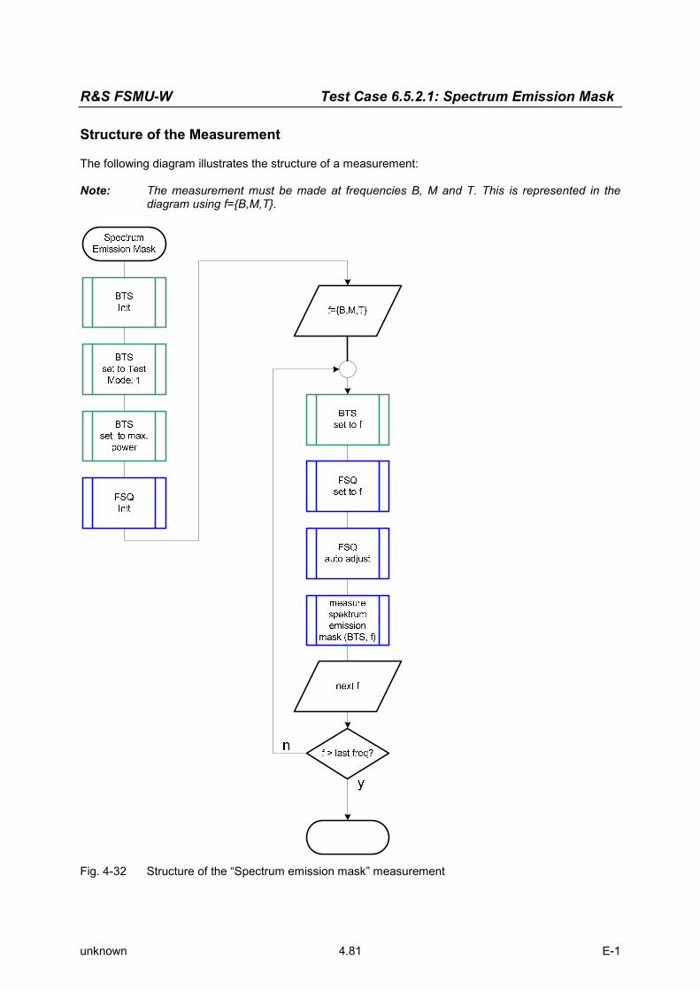
R&S FSMU-W Test Case 6.5.2.1: Spectrum Emission Mask
unknown 4.81 E-1
Structure of the Measurement
The following diagram illustrates the structure of a measurement: Note: The measurement must be made at frequencies B, M and T. This is represented in the
diagram using f={B,M,T}.
Fig. 4-32 Structure of the “Spectrum emission mask” measurement

Test Case 6.5.2.1: Spectrum Emission Mask R&S FSMU-W
unknown 4.82 E-1
Settings on the Base Station
The following table lists the settings to make on the base station: Parameter Value
Output power Maximum power
Test model TM 1
Frequency B, M and T
Scrambling code Any
Antenna diversity OFF
Set the frequency to B, M and T during the course of the measurements. Steps for Carrying Out a Measurement
1. Set the BS to the basic state Test model 1 Set the frequency, for example, to M Maximum output power Switch off antenna diversity mode
2. Set the R&S FSQ to the basic state See Chapter 3, section “Basic State of the R&S FSQ for Measurements on 3G Base Stations”. Internal reference frequency
3. Set the measurement mode Press the MEAS key.
The softkeys for selecting measurements in spectral mode will appear. Press the SPECTRUM EM MASK softkey.
The R&S FSQ will measure the SPECTRUM EMISSION MASK. The softkeys for configuring this measurement will appear.
4. Choose the optimum setting for the reference level and input attenuator of the R&S FSQ Press the ADJUST REF LVL softkey.
The R&S FSQ will make a measurement of the power of the base station and will set the reference level and the attenuator to their optimum values.
5. Read off the result The result will be displayed continuously in the marker field. The R&S FSQ will automatically
choose the proper limit line. The selection is based on the measured carrier power which is also displayed in the marker field.

R&S FSMU-W Test Case 6.5.2.1: Spectrum Emission Mask
unknown 4.83 E-1
Fig. 4-33 Measurement of the spectrum emission mask
6. Generate the peak list You can skip this item if the numeric values of the peaks are not required.
Press the SWEEP key. The sweep configuration menu will appear.
Press the SWEEP SINGLE softkey. The INS will switch over to single sweep. Evaluation of peaks is possible only in this mode (single sweep).
Press the MEAS key. The softkeys for selecting measurements in spectral mode will appear.
Press the SPECTRUM EM MASK softkey. The R&S FSQ will switch over to measure the SPECTRUM EMISSION MASK. The softkeys for configuring this measurement will appear.
Press the MARGIN softkey. This step is necessary only if you wish to change the default value of 6 dB. Enter the desired distance of the peaks from the limit line in the input mask. The subsequent search for peaks will take into account only those peaks with an amplitude that is at least equal to the value of the limit line margin.
Press the PEAKS PER RANGE softkey. This step is necessary only if you wish to change the default value of 25. Enter the desired maximum number of peaks to be searched in the input mask. During the subsequent peak search, the value you entered for this parameter will determine the maximum number of peaks per range that will be taken into account. For more information on ranges, see the section “Adapting the Peak Search” on page 4.85.

Test Case 6.5.2.1: Spectrum Emission Mask R&S FSMU-W
unknown 4.84 E-1
Fig. 4-34 Measurement of the spectrum emission mask
Press the PEAK SEARCH softkey. The peaks will be read in and displayed in the trace. Peaks are taken into account only if they exceed the margin from the limit line.
Press the VIEW PEAK LIST softkey. The peak list will be displayed as shown in the figure below.
Fig. 4-35 Measurement of the peak list for the spectrum emission mask
Interpretation of the Measurement Results
The spectrum is measured in the range ± 7.5 MHz. In the range up to ± 4 MHz, a 30 kHz filter is used for the measurement. In case of larger offsets, a 1 MHz filter is used. The filter is switched automatically within the sweep. An increase in the displayed noise will be displayed at the switchover frequencies. In recording the spectrum, the power of the base station is also measured. The measurement result is used for selecting the limit mask since the standard specifies different limits depending on the power range of the base station.

R&S FSMU-W Test Case 6.5.2.1: Spectrum Emission Mask
unknown 4.85 E-1
To evaluate the spectrum, the limit line measurement function provided by the R&S FSQ is used: If the measured spectrum exceeds the limit line at least at one point, then the limit check will produce a FAIL. The result is displayed continuously on the screen. The “Peak Search” function provided by the R&S FSQ is used to generate a list of the peaks in the trace. It is possible to determine the points in the trace that are closest to the limit or that exceed it by the most. Tips and Special Tricks
Modifying the Peak Search
The peak search is performed in three ranges. Fig. 4-36, “Ranges during measurement of the spectrum emission mask” shows how the ranges are divided for the spectrum mask.
Fig. 4-36 Ranges during measurement of the spectrum emission mask
The softkey PEAKS PER RANGE is used to define the maximum number of peaks to be displayed per range. The maximum permissible value is 50 peaks and the default value is 25. The terms defined below are illustrated graphically in Fig. 4-37, “Parameters for computing the peak list for the spectrum emission mask”. Peaks are displayed only if their value is greater than (Limit – Margin). Limit is determined by the standard, but you can also edit it (see the FS-K72 manual, Chapter “Signal Power Check – SPECTRUM EM MASK”). The MARGIN softkey is used to specify the current value for the margin in limits of -200 dB to +200 dB. The default value is 6 dB.
range 2 range 1 range 3

Test Case 6.5.2.1: Spectrum Emission Mask R&S FSMU-W
unknown 4.86 E-1
Fig. 4-37 Parameters for computing the peak list for the spectrum emission mask
Between two peaks, the measurement curve is expected to drop by at least the "peak excursion”. This keeps too many peaks from being displayed when the signal is noisy. You can edit this value using the PEAK EXCURSION softkey after pressing the MKR FCTN key and the PEAK LIST and PEAK EXCURSION softkeys. The possible range is from 0 dB to 80 dB. The default value is 6 dB. Peaks are not displayed
Cause Peaks in the trace are displayed only in Single Sweep mode. Remedy Switch the INS over to Single Sweep mode.
Press the SWEEP key. The sweep configuration menu will appear.
Press the SWEEP SINGLE softkey.
The INS will switch over to single sweep.
Cause Peaks are displayed only if their level is greater than (Limit-Line – Margin). Peaks below this limit are not displayed. Remedy Increase the margin.
Press the MARGIN softkey. Enter the desired distance of the peaks from the limit line in the input mask. The subsequent search for peaks will take into account only those peaks with an amplitude that is at least equal to the value of the limit line margin.
Peak list
-27
-25
-23
-21
-19
-17
-15 2,144 2,1442 2,1444 2,1446 2,1448 2,145 2,1452 2,1454 2,1456 2,1458
f / GHz
l / dBm
peak peak excursion

R&S FSMU-W Test Case 6.5.2.1: Spectrum Emission Mask
unknown 4.87 E-1
Too many or too few peaks are found
Cause You need to modify the Peak Excursion. Modify Peak Excursion
Press the MKR FCTN key. The menu for configuring the marker measurement functions will appear.
Press the PEAK LIST softkey. The menu for the peak list of the basic INS will appear and the INS will display the peak list.
Press the PEAK EXCURSION softkey. Enter your value in the input field.
Using your own limits
Cause Selection of the limit line is handled in the R&S FSQ based on the measured power of the base station. If the power class of the base station does not agree with the measured power, then the user can specify a fixed value for the limit line. Remedy
Press the MEAS key. The softkeys for selecting measurements in spectral mode will appear.
Press the SPECTRUM EM MASK softkey.
The R&S FSQ will measure the SPECTRUM EMISSION MASK. The softkeys for configuring this measurement will appear.
Press the LIMIT LINE MANUAL softkey.
Select one of the proposed limit lines in the selection box. Cause You wish to use your own limits that do not comply with the standard. Remedy
Depending on the power class, the R&S FSQ selects one of the following limit lines:
Power Limit Line Note
P = 43 dBm 3GBAA Absolute limits
39 dBm = P < 43 dBm 3GBBA
3GBBR
Absolute limits, foffset < 7.5 MHz
Relative limits, foffset = 7.5 MHz
31 dBm = P < 39 dBm 3GBCR Relative limits
< 31 dBm 3GBDA Absolute limits
The limit lines can be modified if necessary.
Press the LINES key. Select the desired limit line (e.g. “3GBAA”) in the selection box.
Press the EDIT LIMIT LINE softkey. The form for editing the selected limit line will appear. After you finish…
Press the SAVE LIMIT LINE softkey. A dialog for entering the name will appear. Leave the suggested name as it is and press ENTER .

Test Case 6.5.2.1: Spectrum Emission Mask R&S FSMU-W
unknown 4.88 E-1
When you see the query (“Limitline exists – Overwrite / Cancel”), you should also confirm it by pressing ENTER .
Note: You can restore the standard limit lines of the R&S FSQ using the following steps:
Press the MEAS key. The softkeys for selecting measurements in spectral mode will appear.
Press the SPECTRUM EM MASK softkey.
The R&S FSQ will measure the SPECTRUM EMISSION MASK. The softkeys for configuring this measurement will appear.
Press the RESTORE STD LIMIT LINES softkey.
Confirm the query (“RESTORE LIMIT LINES… – YES / NO”) by pressing ENTER . Sample Program
Note: All of the procedures with a name that begins with “Fsmu_” are described in Chapter 2, section “General Routines”.
If the peak list is empty, the instrument will not return any list via the IEEE bus. A read operation performed after requesting the list will thus result in a timeout. In the program, the status register is queried to circumvent the timeout. The routines used for this purpose have been tested on an IEEE bus card from National Instruments. The routines might need to be modified for use with cards from other manufacturers.
/* ------------------------- local structures ------------------------- */ /* one element of the peak list as returned by the FSQ */ typedef struct { float frequency ; /* Hz frequency of peak */ float level ; /* dB level of peak */ float delta ; /* dB delta to limitline */ } peak_value ; /*************************************************************************/ void MeasureSpectrumEmissionMask (void) /************************************************************************* * measure the spectrum emission mask of the BTS **************************************************************************/ { /* -------------------- variables ------------------------------------ */ /* ------ change the following variables according to your needs ----- */ double frequency = 2.14 ; /* GHz */ /* -------------- leave the following variables untouched ----------- */ /* -------------- variables for GPIB bus ----------------------------- */ char ib_string [1000] ; /* strings for i/o with gpib bus */ int analyzer ; /* GPIB handle for Analyzer */ short int status ; /* of service register */ char serial_poll ; /* byte of serial poll */ /* ----------------- calculation and result display ------------------ */ char peak_string [1000] ; /* string read in from gpib bus */ char result_string [10000] ; /* strings for result display */ peak_value pk_values [3*50] ; /* max 50 values in 3 ranges */ unsigned int peak_index ; /* used in for loop */ unsigned int length_of_data ; /* of the binary list */

R&S FSMU-W Test Case 6.5.2.1: Spectrum Emission Mask
unknown 4.89 E-1
/* ------------------------------------------------------------------- */ /* ------------------- initialize BTS -------------------------------- */ Fsmu_MessageBox ("*** User Info ***", "Set BTS to Test Model 1, Max Power") ; /* ------------------- initialize FSQ -------------------------------- */ Fsmu_InitFsq(&analyzer) ; Fsmu_SetupInstrumentFsq (analyzer) ; /* ---- Set the instrument to the frequency of the base station ------ */ sprintf (ib_string, ":SENSe1:FREQuency:CENTer %g GHZ", frequency) ; Fsmu_ibWrtln (analyzer, ib_string) ; /* ------------- set instrument to internal trigger ------------------ */ Fsmu_ibWrtln(analyzer, ":TRIGger1:SEQuence:SOURce IMMediate") ; /* ----- Switch on 3GPP-FDD BTS measurement -------------------------- */ /* this sets the instrument to continous sweep implicitely * * ------------------------------------------------------------------- */ Fsmu_ibWrtln(analyzer, "INSTrument:SELect BWCD") ; /* ------------- set instrument to single sweep ---------------------- */ Fsmu_ibWrtln(analyzer, ":INITiate1:CONTinuous OFF") ; /* ------------ Set FSQ to Single Carrier mode ----------------------- */ /* Multi Carrier not allowed for ths measurement */ if (Fsmu_GetMultiCarrier ()) { Fsmu_MessageBox ("*** ERROR ***", "Multicarrier must be off for this measurement") ; return ; } else Fsmu_ibWrtln (analyzer, ":CONFigure:WCDPower:BTS:MCARrier:STATe OFF"); /* ------------ set FSQ to measure spectrum emission mask ------------ */ Fsmu_ibWrtln(analyzer, ":CONFigure:WCDPower:MEASurement ESPectrum") ; /* --------- perform an auto adjust the FSQ settings ----------------- */ /* and wait for the command execution */ Fsmu_ibWrtln(analyzer, ":SENSe:POWer:ACHannel:PRESet:RLEVel;*OPC?") ; Fsmu_ibRd (analyzer, ib_string, sizeof (ib_string)) ; /* --------------- trigger FSQ and wait for result ------------------- */ Fsmu_ibWrtln (analyzer, "INITiate:IMMediate;*OPC?") ; Fsmu_ibRd (analyzer, ib_string, sizeof (ib_string)) ; /* ---------------- check limit line, if BTS failed ------------------ */ Fsmu_ibWrtln (analyzer, ":CALCulate:LIMit:FAIL?") ; Fsmu_ibRdln (analyzer, ib_string, sizeof (ib_string)) ; /* ----------------- prepare the result ------------------------------ */ if (atoi (ib_string) == 0) strcpy (result_string, "emission mask is within limits\n") ; else strcpy (result_string, "emission mask is outside limits!\n") ; /* ------------------------------------------------------------------- */ /* -------- let FSQ search maximum values in each range -------------- */

Test Case 6.5.2.1: Spectrum Emission Mask R&S FSMU-W
unknown 4.90 E-1
/* ------------------------------------------------------------------- */ /* ----------- set margin for peak list to 20 dB --------------------- */ Fsmu_ibWrtln (analyzer, ":CALCulate1:PEAKsearch:MARGin 20dB") ; /* ---------------- set number of peaks per range to 3 --------------- */ Fsmu_ibWrtln (analyzer, ":CALCulate1:PEAKsearch:SUBRanges 3") ; /* ----------------- clear status registers -------------------------- */ Fsmu_ibWrtln (analyzer, "*CLS") ; /* -------------- calculate the peak list and wait for result -------- */ Fsmu_ibWrtln (analyzer, ":CALCulate1:PEAKsearch;*OPC?") ; Fsmu_ibRd (analyzer, ib_string, sizeof (ib_string)) ; /* ------------------ read in the peaks, if any available ------------ */ /* Note: if no peaks available, the operation TRACe? FINal1 leads to * an error and an ibRead after the operation runs into a time out * * SRQ can be used, to indicate, which of the two events occured * see user manual of FSQ for further explanation of the SRQ handling */ /* ------------------------------------------------------------------- * Set mask for service request in the SRE register: * enable SRQ for error event (0x04) and measurement available (0x10) * 0x14 = 20: ESB + MAV + ErrorQueue * * contents of status register (STB) * * +-+-+-+-++-+-+-+-+ * |7|6|5|4||3|2|1|0| * +---+---++---+---+ * | | | | | | | +-- 0x01: not used * | | | | | | +---- 0x02: not used * | | | | | +------ 0x04: error/event queue <--------- * | | | | +-------- 0x08: Status Questionable * | | | +----------- 0x10: MAV: measurement available <--------- * | | +------------- 0x20: ESB register * | +--------------- 0x40: RQS/MSS: SRQ sent by this device * +----------------- 0x80: Status Operation * * we enable error/event queue and MAV for SRQ * ------------------------------------------------------------------- */ Fsmu_ibWrtln (analyzer, "*SRE 20") ; /* ------------ read in the peak list, in binary format ------------- */ /* this produces an SRQ, either due to data or due to an error */ Fsmu_ibWrtln (analyzer, ":FORMAT REAL,32;:TRACe? FINal1") ; /* ------------------------------------------------------------------- */ /* ----------------- Check, if data are available; ------------------- */ /* ------------------------------------------------------------------- */ /* ------------------ Wait for SRQ ----------------------------------- */ /* either due to an error, or due to a measurement result * * status = 0: no srq occured; (should not occur) * * this function sets time out for the service request to 3 sec * * (the time out has to be set on board level in this case *

R&S FSMU-W Test Case 6.5.2.1: Spectrum Emission Mask
unknown 4.91 E-1
* */ /* ---------------------- wait 3 seconds for SRQ --------------------- */ status = Fsmu_ibWaitForSRQ (0, T3s) ; /* ------------- check, if we got an SRQ or a time out --------------- */ if (status) { /* ---------------------------- an SRQ occured --------------------- */ /* read in the status register via serial poll; * * an *ESR would interrupt the query above * * */ Fsmu_ibRsp (analyzer, &serial_poll) ; /* ------ bit 2 is set, if there is an error in the queue ---------- */ /* this occures here, if no peak data are available; so we get: * -200,"Execution error;Function not available;:TRACe? FINal1" */ if (serial_poll & 0x04) { /* we read in the error queue, to empty it */ Fsmu_ibWrtln(analyzer, ":SYSTem:ERRor?") ; Fsmu_ibRd (analyzer, ib_string, sizeof (ib_string)) ; strcat (result_string, "no peaks found"); } /* --------- if bit 5 is set, data are available ------------------- */ if (serial_poll & 0x10) { /* -------------------------------------------------------------- * * read in the data in binary format * format of binary data: * #dlll<data> * # start identifier * d one ascii digit, defining the length of the next field * lll ascii digits, defining the number of bytes which follow * number of l's is defined by "d", see above * no terminating '\0' * <data> data in 4 byte ieee float format; * can directly stored in a bloat field */ /* -------------------------- skip the '#' ----------------------- */ Fsmu_ibRd (analyzer, ib_string, 1) ; /* ------------------------- read in 'd'-------------------------- */ Fsmu_ibRd (analyzer, ib_string, 1) ; /* ---------------------read in 'lll'; length--------------------- */ length_of_data = ib_string [0] - '0' ; Fsmu_ibRd (analyzer, ib_string, length_of_data) ; ib_string [length_of_data] = '\0' ; length_of_data = atoi (ib_string) ; /* ----------------- read in data with one call ------------------ */ Fsmu_ibRd (analyzer, pk_values, length_of_data) ;

Test Case 6.5.2.1: Spectrum Emission Mask R&S FSMU-W
unknown 4.92 E-1
/* ---------------- read in trailing LF from FSQ ----------------- */ Fsmu_ibRd (analyzer, ib_string, 1) ; /* ---------------- prepare the result string ------------------- */ strcat (result_string, " =======================================\n"); strcat (result_string, " Nr freq level margin\n"); strcat (result_string, " =======================================\n"); for (peak_index = 0 ; peak_index < length_of_data / sizeof (pk_values[0]); peak_index ++) { sprintf (peak_string, "%3d %10.6f MHz %7.2f dBm %7.2f dB\n", peak_index, pk_values [peak_index].frequency/1E6, pk_values [peak_index].level, pk_values [peak_index].delta) ; strcat (result_string, peak_string) ; } } } /* of if (status) */ else { strcat (result_string, "no SRQ detected!\n" "This may be due to auto srq-polling of your gpib driver\n" "please reconfigure your gpib-driver"); /* we read in the error queue, to empty it */ Fsmu_ibWrtln(analyzer, ":SYSTem:ERRor?") ; Fsmu_ibRd (analyzer, ib_string, sizeof (ib_string)) ; } /* --------------------- display the results ------------------------- */ Fsmu_MessageBox ("*** Results ***", result_string) ; /* --------------------- close FSQ on GPIB --------------------------- */ Fsmu_CloseFsq (analyzer) ; }

R&S FSMU-W Test Case 6.5.2.2: Adjacent Channel Leakage Power Ratio (ACLR)
unknown 4.93 E-1
Test Case 6.5.2.2: Adjacent Channel Leakage Power Ratio (ACLR)
Test Objective
This test is used to verify that the transmitted power of the base station in the adjacent channels does not exceed the specified limit. Quotation from [1]:
Adjacent Channel Leakage power Ratio (ACLR) is the ratio of the RRC filtered mean power centered on the assigned channel frequency to the RRC filtered mean power centered on an adjacent channel frequency. The requirements shall apply whatever the type of transmitter considered (single carrier or multi-carrier). It applies for all transmission modes foreseen by the manufacturer's specification.
Test Setup
The measurement can be performed using the standard test setup (see Chapter 3, section “Standard Test Setup with R&S FSQ”). Only the R&S FSQ is required to perform the measurement: Internal triggering (“FREE RUN”) and the internal reference frequency of the R&S FSQ are sufficient.
Fig. 4-38 Test setup for “Adjacent Channel Leakage Power Ratio (ACLR)”
The input power on the R&S FSQ may not exceed 30 dBm. The value of the attenuator R1 must be chosen accordingly.
Recommended Options
The measurement can be performed without any additional options. Variation in the Parameters of the Base Station
The measurement must be made at the three frequencies B, M and T. Peculiarities for Multicarrier
In multicarrier mode, the adjacent emissions in the adjancent channels are measured above the carrier at the highest frequency and below the carrier at the lowest frequency. The R&S FSQ handles this job automatically in multicarrier mode.

Test Case 6.5.2.2: Adjacent Channel Leakage Power Ratio (ACLR) R&S FSMU-W
unknown 4.94 E-1
Fig. 4-39 “Adjacent Channel Leakage Power Ratio (ACLR) with four carriers”

R&S FSMU-W Test Case 6.5.2.2: Adjacent Channel Leakage Power Ratio (ACLR)
unknown 4.95 E-1
Structure of the Measurement
The following diagram illustrates the structure of a measurement: Note: The measurement must be made at frequencies B, M and T. This is represented in the
diagram using f={B,M,T}.
Fig. 4-40 tructure of the “Adjacent Channel Leakage power Ratio (ACLR)“ measurement
Settings on the Base Station
The following table lists the settings to make on the base station: Parameter Value
Output power Maximum power
Multicarrier: All carriers ON
Test model TM 1
Frequency B, M and T
Scrambling code Any
Antenna diversity OFF
Set the frequency to B, M and T during the course of the measurements.

Test Case 6.5.2.2: Adjacent Channel Leakage Power Ratio (ACLR) R&S FSMU-W
unknown 4.96 E-1
Steps for Carrying Out a Measurement
1. Set the BS to the basic state Test model 1 Set the frequency, for example, to M All carriers at maximum output power Switch off antenna diversity mode
2. Set the R&S FSQ to the basic state See Chapter 3, section “Basic State of the R&S FSQ for Measurements on 3G Base Stations”. Internal reference frequency The default for the measurement is the channel with code 0, i.e. the CPICH.
3. Switch on multicarrier You will have to skip this step for a single carrier base station.
Press the SETTINGS hotkey. The softkeys for configuring the code domain parameters will appear.
Press the NEXT key. The side menu for the settings will open.
Press the MULTI CARR ON OFF softkey. The INS will switch to multicarrier mode and the green marker will switch from OFF to ON.
4. Set the Single Carrier measurement mode You will have to skip this step for a multicarrier base station.
Press the MEAS key. The softkeys for selecting measurements in spectral mode will appear.
Press the CHAN PWR ACP softkey. The R&S FSQ will measure the ACLR. The softkeys for configuring this measurement will appear.
Press the OCCUPIED BANDWIDTH softkey. The R&S FSQ will measure the OCCUPIED BANDWIDTH. The softkeys for configuring this measurement will appear.
5. Set the multicarrier measurement mode You will have to skip this step for a single carrier base station.
Press the MEAS key. The softkeys for selecting measurements in spectral mode will appear.
Press the MULT CARR ACLR softkey. The R&S FSQ will measure the ACLR. The softkeys for configuring this measurement will appear.
Press the CP / ACP CONFIG softkey. The menu for configuring the ACLR measurement will appear.
Press the NO. OF TX CHAN softkey. Enter the desired number of carriers in the input field.
Press the PREV key. The menu for the multicarrier ACLR measurement will appear again.
6. Choose the optimum setting for the reference level and input attenuator of the R&S FSQ Press the ADJUST REF LVL softkey.
The R&S FSQ will make a measurement of the power of the base station and will set the reference level and the attenuator to their optimum values.
7. Read off the result The results will be displayed continuously in the marker field.

R&S FSMU-W Test Case 6.5.2.2: Adjacent Channel Leakage Power Ratio (ACLR)
unknown 4.97 E-1
Fig. 4-41 Measurement of the ACLR for a single carrier base station
Fig. 4-42 Measurement of the ACLR for a multi carrier base station
Interpretation of the Measurement Results
The measured carrier power level(s) and the relative power in the adjacent channels are displayed in the marker field. When measuring the ACLR for a multicarrier base station, the aggregate power of the base station and the reference channel for specifying the power in the adjacent channel are also indicated. The results will be displayed continuously on the screen. Tips and Special Tricks
Changing the Number of Adjacent Channels Displayed
The channel power can be measured and displayed for one to three adjacent channels.

Test Case 6.5.2.2: Adjacent Channel Leakage Power Ratio (ACLR) R&S FSMU-W
unknown 4.98 E-1
Changing the number of adjacent channels displayed (opt.) Press the CP / ACP CONFIG softkey.
The menu for configuring the ACLR measurement will appear. Press the NO. OF ADJ CHAN softkey.
Enter the desired number of adjacent channels (1 to 3) in the input field (or use the rotary knob). Setting the Reference Channel
To measure the relative power in the adjacent channels on a multicarrier base station, you must specify the reference channel for the power levels. The R&S FSQ allows you to choose from the following:
• Absolute indication of the channel: The reference channel is defined by its channel number
• Channel with the lowest power level
• Channel with the highest power level
• Channel with the lowest frequency for the adjacent channels in the lower frequency range; Channel with the highest frequency for the adjacent channels in the upper frequency range
Set the reference channel to carriers with the lowest and highest frequency (opt.)
Press the ACP REF SETTINGS softkey. The menu for selecting the ACP reference channel will appear.
Use the rotary knob or cursor keys to select “LOWEST & HIGHEST CHANNEL” and use the ENTER key to accept this entry.
Increasing the Measurement Dynamic Range through Noise Correction
The measurement dynamic range of the R&S FSQ can be increased further by taking into account the intrinsic noise of the R&S FSQ in the displayed signal. The R&S FSQ will do this automatically if noise correction is switched on. Switch on noise correction (opt.)
Press the NOISE CORR ON OFF softkey. The green marker will switch from OFF to ON. The R&S FSQ will now measure its intrinsic noise and take this into account in displaying the measurement results.
A
Att 10 dB SWT 100 ms*
1 RMCLRWR
Ref 56.8 dBm
Center 2.14 GHz 10 ms/
LVL
-40
-30
-20
-10
0
10
20
30
40
50
Tx Channel W-CDMA 3GPP FWD Bandwidth 5 MHz Power 43.19 dBm
Fig. 4-43 Measuring the ACLR with “Fast ACP“

R&S FSMU-W Test Case 6.5.2.2: Adjacent Channel Leakage Power Ratio (ACLR)
unknown 4.99 E-1
Speeding Up the Measurement
Measurement of the ACLR is performed in the R&S FSQ in compliance with the standard using a sweep of a 30 kHz filter. Depending on the distance to the carrier(s), the reference level is automatically adjusted so as to achieve the widest possible measurement dynamic range. However, it is also possible to make the measurement in zero span with channel filters which are set one after another to the carrier(s) and the adjacent channels. This will speed up the measurement, but it does have the effect of somewhat reducing the dynamic range particularly in the first adjacent channel. Set Fast ACLR (opt.)
Press the FAST ACLR ON OFF softkey. The green marker will switch from OFF to ON, and the R&S FSQ will measure the ACLR using channel filters. Measurement of the individual carriers takes place in zero span, which will naturally change what is displayed.
Fig. 4-44 Measuring the ACLR with “Fast ACP“
Sample Program: Measurement with the Analyzer
Note: All of the procedures with a name that begins with “Fsmu_” are described in Chapter 3, section “General Routines”. /*************************************************************************/ void MeasureAdjacentChannelLeakageRatio (void) /************************************************************************* * measure the Adjacent Channel Leakage Power Ratio (ACLR) of the BTS *************************************************************************/ { /* -------------------- variables ------------------------------------ */ /* ------ change the following variables according to your needs ----- */ double frequency = 2.14 ; /* GHz */ int num_of_carriers = 4 ; /* for multi carrier BTS only */ /* -------------- leave the following variables untouched ----------- */ /* -------------- variables for GPIB bus ----------------------------- */ char tmp_string [80] ; /* string to hold tmp. result */ char ib_string [1000] ; /* strings for i/o with gpib bus */ int analyzer = 0 ; /* GPIB handle for analyzer */ int generator = 0 ; /* GPIB handle for generator */ /* ----------------- calculation and result display ------------------ */ char result_string [10000] ; /* strings for result display */

Test Case 6.5.2.2: Adjacent Channel Leakage Power Ratio (ACLR) R&S FSMU-W
unknown 4.100 E-1
int count ; /* number of results */ int lindex ; /* for result loop */ float results [100] ; /* of trace */ /* ------------------------------------------------------------------- */ /* ------------------- initialize BTS -------------------------------- */ Fsmu_MessageBox ("*** User Info ***", "Set BTS to Test Model 1, Max Power\n" "all carriers on, if multi carrier BTS") ; /* ------------------- initialize FSQ -------------------------------- */ Fsmu_InitFsq(&analyzer) ; Fsmu_SetupInstrumentFsq (analyzer) ; /* ------------------ set instrument to internal --------------------- */ Fsmu_ibWrtln(analyzer, ":TRIGger1:SEQuence:SOURce IMMediate") ; /* ----- Switch on 3GPP-FDD BTS measurement -------------------------- */ /* this sets the instrument to continous sweep implicitely * * ------------------------------------------------------------------- */ Fsmu_ibWrtln(analyzer, "INSTrument:SELect BWCD") ; /* ------------------------ single sweep ----------------------------- */ Fsmu_ibWrtln(analyzer, ":INITiate1:CONTinuous OFF") ; /* ------- different measurements for single and multi carrier ------- */ if (!Fsmu_GetMultiCarrier ()) { /* ----------------------------------------------------------------- */ /* ------------------- single carrier BTS ------------------------- */ /* ----------------------------------------------------------------- */ Fsmu_ibWrtln (analyzer, "CONFigure:WCDPower:BTS:MCARrier:STATe OFF"); /* ------------ set FSQ to measure (single carrier) aclr ----------- */ Fsmu_ibWrtln(analyzer, ":CONFigure:WCDPower:MEASurement ACLR") ; /* ------------------ single carrier ACLR ------------------------- */ Fsmu_ibWrtln(analyzer, "SENSe1:POWer:ACHannel:PRESet ACPower") ; /* ------- measure power of carrier and 3 adjacent channels -------- */ Fsmu_ibWrtln(analyzer, ":SENSe:POWer:ACHannel:ACPairs 3") ; /* --- set the instrument to the frequency of the base station ----- */ /* do this *after* setting the measurement mode to suppress * automatic settings of the frequency of the instrument */ sprintf (ib_string, ":SENSe1:FREQuency:CENTer %g GHZ", frequency) ; Fsmu_ibWrtln (analyzer, ib_string) ; /* --------------- auto adjust the FSQ settings -------------------- */ /* wait for the command execution */ Fsmu_ibWrtln(analyzer, ":SENSe:POWer:ACHannel:PRESet:RLEVel;*OPC?") ; Fsmu_ibRd (analyzer, ib_string, sizeof (ib_string)) ; /* --------------- trigger FSQ and wait for result ----------------- */ Fsmu_ibWrtln (analyzer, "INITiate:IMMediate;*OPC?") ; Fsmu_ibRd (analyzer, ib_string, sizeof (ib_string)) ; /* ----------------------- read in the result ---------------------- */ Fsmu_ibWrtln (analyzer,

R&S FSMU-W Test Case 6.5.2.2: Adjacent Channel Leakage Power Ratio (ACLR)
unknown 4.101 E-1
":CALCulate:MARKer:FUNCtion:POWer:RESult? ACPower") ; Fsmu_ibRd (analyzer, ib_string, sizeof (ib_string)) ; num_of_carriers = 1 ; } else { /* ----------------------------------------------------------------- */ /* -------------------- multi carrier BTS -------------------------- */ /* ----------------------------------------------------------------- */ Fsmu_ibWrtln (analyzer, ":CONFigure:WCDPower:BTS:MCARrier:STATe ON"); /* ----------------- measure (multi carrier) ACLR ------------------ */ Fsmu_ibWrtln(analyzer, ":CONFigure:WCDPower:MEASurement MCACLR") ; /* -------------------- x carriers are on -------------------------- */ sprintf (ib_string, ":SENSe:POWer:ACHannel:TXChannel:COUNt %d", num_of_carriers) ; Fsmu_ibWrtln(analyzer, ib_string) ; /* ----- measure power of all carriers and 3 adjacent channels ----- */ Fsmu_ibWrtln(analyzer, ":SENSe:POWer:ACHannel:ACPairs 3") ; /* --- measure adjacent channels rel. to lowest / highest carrier -- */ Fsmu_ibWrtln(analyzer, "POWer:ACHannel:REFerence:TXCHannel:AUTO LHIGhest") ; /* --- set the instrument to the frequency of the base station ----- */ /* do this *after* setting the measurement mode to suppress * automatic settings of the frequency of the instrument */ sprintf (ib_string, ":SENSe1:FREQuency:CENTer %g GHZ", frequency) ; Fsmu_ibWrtln (analyzer, ib_string) ; /* ------------- auto adjust the FSQ settings ---------------------- */ /* wait for the command execution */ Fsmu_ibWrtln(analyzer, ":SENSe:POWer:ACHannel:PRESet:RLEVel;*OPC?") ; Fsmu_ibRd (analyzer, ib_string, sizeof (ib_string)) ; /* --------------- trigger FSQ and wait for result ----------------- */ Fsmu_ibWrtln (analyzer, "INITiate:IMMediate;*OPC?") ; Fsmu_ibRd (analyzer, ib_string, sizeof (ib_string)) ; /* ----------------------- read in the result ---------------------- */ Fsmu_ibWrtln (analyzer, ":CALCulate:MARKer:FUNCtion:POWer:RESult? MCACpower") ; Fsmu_ibRd (analyzer, ib_string, sizeof (ib_string)) ; } /* ------------------- prepare print out of the result --------------- */ sprintf (result_string , "ACLR measurement:\n\n") ; count = Fsmu_ConvertFsqResultTrace (ib_string, results, sizeof (results) / sizeof (results[0])) ; /* number of carriers * + total power (only if multi carrier) * + 3 pairs of adjacent channels * */ if (count != (num_of_carriers + ((num_of_carriers > 1)?1:0) + 3*2)) {

Test Case 6.5.2.2: Adjacent Channel Leakage Power Ratio (ACLR) R&S FSMU-W
unknown 4.102 E-1
sprintf (tmp_string, "format error, count = %d, should be %d\n", count, num_of_carriers + 1 + 3*2 ) ; strcat (result_string, tmp_string) ; } for (lindex = 0 ; lindex < num_of_carriers; lindex ++) { sprintf (tmp_string, "(Ch %1d): %7.2f dBm\n", lindex, results[lindex]) ; strcat (result_string, tmp_string) ; } lindex = num_of_carriers ; /* ---- total power is only displayed in multi carrier environment --- */ if (num_of_carriers > 1) { sprintf (tmp_string, "total: %7.2f dBm\n", results[lindex ++]) ; strcat (result_string, tmp_string) ; } sprintf (tmp_string, "lower adjacent: %7.2f dB\n", results[lindex++]) ; strcat (result_string, tmp_string) ; sprintf (tmp_string, "upper adjacent: %7.2f dB\n", results[lindex++]) ; strcat (result_string, tmp_string) ; sprintf (tmp_string, "lower alternate: %7.2f dB\n", results[lindex++]) ; strcat (result_string, tmp_string) ; sprintf (tmp_string, "upper alternate: %7.2f dB\n", results[lindex++]) ; strcat (result_string, tmp_string) ; sprintf (tmp_string, "lower 2nd alt: %7.2f dB\n", results[lindex++]) ; strcat (result_string, tmp_string) ; sprintf (tmp_string, "upper 2nd alt: %7.2f dB\n", results[lindex++]) ; strcat (result_string, tmp_string) ; /* ----------------- display the result ------------------------------ */ Fsmu_MessageBox ("*** Result ***", result_string) ; /* -------------------- close FSQ on GPIB ---------------------------- */ Fsmu_CloseFsq (analyzer) ; }

R&S FSMU-W Test Case 6.5.3: Spurious Emissions
unknown 4.103 E-1
Test Case 6.5.3: Spurious Emissions
Test Objective
Quotation from [1]:
Spurious emissions are emissions which are caused by unwanted transmitter effects such as harmonics emission, parasitic emission, intermodulation products and frequency conversion products, but exclude out of band emissions. This is measured at the base station RF output port. The requirement applies at frequencies within the specified frequency ranges, which are more than 12.5 MHz under the first carrier frequency used or more than 12.5 MHz above the last carrier frequency used. The requirements shall apply whatever the type of transmitter considered (single carrier or multi-carrier). It applies for all transmission modes foreseen by the manufacturer's specification. Unless otherwise stated, all requirements are measured as mean power (RMS).
This test measures the spurious emissions of the base station with a spacing from the carrier of 12.5 MHz and compares them against specified limits. In this example, a 2-carrier BS is assumed which transmits at the two lowest frequencies in operating band I (2110 MHz and 2115 MHz). What is described is a test of the spurious emissions for category B (sect. 6.5.3.4.2). Example
In this example, a 2-carrier BS is assumed which transmits at the two lowest frequencies in operating band I (2110 MHz and 2115 MHz). What is described is a test of the spurious emissions for category B (sect. 6.5.3.4.2). Test Setup
Spurious Emissions, Category A, B
Measurement of spurious emissions according to category A ([1], section 6.5.3.4.1) and category B ([1], section 6.5.3.4.2) is possible using the standard test setup (see Chapter 3, section “Standard Test Setup with R&S FSQ”). Only the R&S FSQ is required to perform the measurement: Internal triggering (“FREE RUN”) and the internal reference frequency of the R&S FSQ are sufficient. When you are selecting the attenuator R1, recall that the frequency range must suffice up to 12.75 GHz (R&S FSQ26 and higher) or 8 GHz (R&S FSQ8) or 3.6 GHz (R&S FSQ3).
Fig. 4-45 Test setup for “Spurious emissions’”
The input power on the R&S FSQ may not exceed 30 dBm. The value of the attenuator R1 must be chosen accordingly.

Test Case 6.5.3: Spurious Emissions R&S FSMU-W
unknown 4.104 E-1
Protection of Services, Co-Existence, Co-Variance
The following measurements are extremely demanding in terms of the expected measurement dynamic range of the spectrum analyzer and require the use of an external filters:
• “Protection of the BS receiver of own or different BS”
• Co-existance with other services
• Co-location with other services
Fig. 4-46 Test setup for “Protection of other services, co-existance und co-location”
The input power on the R&S FSQ may not exceed 30 dBm. The value of the attenuator R1 must be chosen accordingly.
Recommended Options
Spurious emissions in compliance with category A and B can be measured without any additional options. In order to test the “Protection of other services, co-existance and co-location”, you will need either an external preamplifier or the option B25, “RF Preamplifier” (R&S FSQ3 and R&S FSQ8) or option B25 and B23 (R&S FSQ26). Variation in the Parameters of the Base Station
The measurement must be made at frequencies B, M and T. Peculiarities for Multicarrier
When testing a single carrier base station, the spurious emissions are measured at a spacing of 12.5 MHz from the carrier.
Fig. 4-47 Measurement range for spurious emissions (single carrier)
When testing under multicarrier conditions, the spurious emissions are measured outside of the frequency band used by all of the carriers.

R&S FSMU-W Test Case 6.5.3: Spurious Emissions
unknown 4.105 E-1
Fig. 4-48 Measurement range for spurious emissions (multicarrier)
Structure of the Measurement
The following diagram illustrates the structure of a measurement: Note: The measurement must be made at frequencies B, M and T. This is represented in the
diagram using f={B,M,T}.
Fig. 4-49 Structure of the “Spurious emissions“ measurement
Settings on the Base Station
The following table lists the settings to make on the base station: Parameter Value
Output power Maximum power
Test model TM 1
Frequency B, M and T

Test Case 6.5.3: Spurious Emissions R&S FSMU-W
unknown 4.106 E-1
The other parameters such as the scrambling code, etc can be set to any value. Set the frequency to B, M and T during the course of the measurements. Steps for Carrying Out a Measurement
1. Set the BS to the basic state Test model 1 Set the frequency, for example, to M Maximum output power Any scrambling code
2. Set the R&S FSQ to the basic state The spurious emissions are measured using a special measurement function provided by the basic INS. In this test, it is assumed that you are starting from the INS’s basic state.
Press the PRESET key. This will put the INS in its predefined basic state. (See the R&S FSQ Manual, Chapter 4, “Basic Settings of the R&S FSQ – PRESET Key”.)
3. Set Single Sweep mode You can skip this step but they instrument will continue measuring continuously. For use in searching for peaks, you must select Single Sweep mode.
Press the SWEEP key. The sweep configuration menu will appear.
Press the SWEEP SINGLE softkey. The INS will switch over to single sweep.
4. Set Limit Lines The figures used in the following example apply to a base station with two carriers, fc1 = 2110 MHz, fc2 = 2115 MHz (i.e. in the lower frequency range).
Press the LINES key. The menu for creating and editing limit lines will appear.
Press the NEW LIMIT LINE softkey. A form for creating and editing a new limit line will appear. Fill out the form as follows:
Fig. 4-50 Limit line for “Spurious emissions“

R&S FSMU-W Test Case 6.5.3: Spurious Emissions
unknown 4.107 E-1
Finish inputting a frequency by pressing the GHz , MHz , kHz or Hz key. Finish inputting a limit by pressing, for example, the dB key.
5. Enter Sweep Ranges You can use sweep ranges to configure and measure spurious emissions in the entire specified frequency band. A separate range is defined for each setting of the R&S FSQ or the test setup. You can enter transducer tables in each range in order to take into account the frequency response of external test equipment. Optionale breakpoints at the end of the ranges make it possible to switch the test equipment in manual mode or under remote control.
The INS’s specified default table defines the measurement in compliance with ITU-R SM.329 ([2]), which is also how it is used in TS25.141 ([1]). As part of the measurement, the changed limits in the vicinity of the carriers must be taken into account as well as any possible changes in the test equipment.
Press the MEAS key.
The menu for configuring the measurement applications will appear. Press the SPURIOUS EMISSIONS softkey.
The menu for configuring and performing the spurious emissions measurement will appear. Press the SWEEP LIST softkey.
The menu for editing the sweep list will appear. Press the EDIT SWEEP LIST softkey.
The form for entering sweep lists will appear.
Fig. 4-51 Form for entering sweep lists”
To enter three further ranges, use the cursor keys to go into the 4th range and press the INS AFTER RANGE softkey three times.
In Range 4, change the stop frequency from 12.75 GHz to 2.09 GHz, reduce the number of sweep points to 5001, input the transducer table as, for example, “wideband” and set “Stop after sweep” to ON.
In Ranges 1-3, input the transducer table as, for example, “wideband”. Ranges Bereiche 5 and 6 measure the spurious emissions in the inband range. Accordingly,
input the transducer table as “inband” in these ranges. In order to enable a switch of the external connection, “Stop after sweep” was set to ON in Range 4.
To summarize, the values in Ranges 1 to 5 should be entered as follows:

Test Case 6.5.3: Spurious Emissions R&S FSMU-W
unknown 4.108 E-1
Fig. 4-52 Ranges 6 and 7 when entering the sweep lists
The values in Ranges 6 to 7 should be entered as follows:
Fig. 4-53 Ranges 6 and 7 when entering the sweep lists
6. Start the measurement Press the START SWEEP softkey.
The sweep is performed up to the first stopping point. The user can now modify the external connections if required.
Press the ENTER softkey. The sweep is performed up to the second stopping point. The user can now modify the external connections if required.

R&S FSMU-W Test Case 6.5.3: Spurious Emissions
unknown 4.109 E-1
Fig. 4-54 User input when making measurements with sweep lists
7. Generate the peak list You can skip this item if the numeric values of the peaks are not required. To create the peak list, the R&S FSQ’s Single Sweep mode must be switched on (see Step 3).
Press the MARGIN softkey. This step is necessary only if you wish to change the default value of 6 dB. Enter the desired distance of the peaks from the limit line in the input mask. The subsequent search for peaks will take into account only those peaks with an amplitude that is at least equal to the value of the limit line margin.
Press the PEAKS PER RANGE softkey. This step is necessary only if you wish to change the default value of 25. Enter the desired maximum number of peaks to be searched in the input mask. During the subsequent peak search, the value you entered for this parameter will determine the maximum number of peaks per range that will be taken into account.
Press the PEAK SEARCH softkey. The peaks will be read in and displayed in the trace. Peaks are taken into account only if they exceed the margin from the limit line.

Test Case 6.5.3: Spurious Emissions R&S FSMU-W
unknown 4.110 E-1
Fig. 4-55 Peaks for “Spurious emissions”
Press the VIEW PEAK LIST softkey. The peak list will be displayed as shown in the figure below.
Fig. 4-56 Display of the peak list for spurious emissions

R&S FSMU-W Test Case 6.5.3: Spurious Emissions
unknown 4.111 E-1
Tips and Special Tricks
Application Note
For information on measuring spurious emissions using spectrum analyzers from Rohde & Schwarz, we suggest you read Rohde & Schwarz Application Note 1EF45 “Spurious Emission Measurement on 3GPP Base Station Transmitters” ([3]). The Application Note provides details on the recommended analyzer settings. The settings required on the R&S FSQ are the same as those described in the Application Note for the FSU. A copy of the Application Note is included with the CD-ROM. Modifying the Peak Search
The peak search uses the same algorithm as the measurement of the spectrum emission mask (see the section “Spectrum Emission Mask” on page 4.80). The instructions for configuring the peak search also apply when searching for peaks with spurious emissions. Using Filters
Due to its excellent drive characteristics, the R&S FSQ is capable of measuring spurious emissions on base stations in category A ([1], section 6.5.3.4.1) and B ([1], section 6.5.3.4.2) without any additional filters or amplifiers. To protect the R&S FSQ from the high power level of the base station, all that is required is an approx. 30 dB attenuator. For these applications, you can use the standard setup (see Fig. 4-45: Test setup for “Spurious emissions” on page 4.103). When measuring spurious emissions in the receiving bands specified by the different mobile radio standards ([1], section 6.5.3.4.3ff), the expectations for the dynamic range of the analyzer are so high that it is not possible to make this measurement without using external filters. The filter needs to reduce the power of the carrier in the base station by at least 60 dB. An attenuator with a value of approx. 10 dB should be connected in front of the filter to keep the VSWR from getting too high for the base station. The input sensitivity of the R&S FSQ is sufficient when equipped with the optional preamplifier (Option FSU-B25). Measuring Subranges
In order to be able to quickly verify suspected interferers, you can restrict the frequency range of the measurement in the Frequency menu. 8. Restrict the frequency range
Press the FREQ key. The Frequency menu should appear.
Press the START softkey. Use the keypad to enter the desired start frequency in the input field and finish by pressing the MHz key. You can enter the frequency in units of GHz, MHz, kHz and Hz.
Press the STOP softkey. Use the keypad to enter the desired stop frequency in the input field and finish by pressing the MHz key. You can enter the frequency in units of GHz, MHz, kHz and Hz.
The measurement will be performed in the frequency ranges specified by the ranges. The frequency limits entered using Start and Stop will also be taken into account. It is also possible to use only parts of a range. For example, you can measure in the range of the 3rd harmonic by entering 6.31 GHz as the start frequency and 6.35 GHz as the stop frequency. Limit Lines
Limit lines are used for automatic monitoring of limits. They are also used during creation of the peak lists. Peaks are entered into the list only if they exceed the limit line by a defined minimum distance. In the case of spurious emissions, two ranges need to be taken into account for the limit lines:

Test Case 6.5.3: Spurious Emissions R&S FSMU-W
unknown 4.112 E-1
Outside of the frequency range of the base station defined by 3GPP (“Operating Band I, II and III”), fixed limits apply that are independent of the transmit frequency of the base station. Within the band, limits apply that become increasingly stringent at greater distances from the carrier frequencies. Within a spacing of 12.5 MHz from the carriers, spurious emissions are not measured. There, the “spectrum emissions mask” is used. The following figure shows how the limits behave near to the operating band of the base station.
Fig. 4-57 Limits near the transmit band for spurious emissions
The R&S FSQ’s limit lines are created and handled independently of the spurious emissions application. A separate limit line must be created for each frequency of the base station. Since the 12.5 MHz range around the carrier(s) is excluded using the range lists, special handling in the limit lines is no longer necessary. Sample Program
Note: All of the procedures with a name that begins with “Fsmu_” are described in Chapter 2, section “General Routines”.
/* ------------------------- local structures ------------------------- */ /* --------- conditions of the SRQ handling routine -------------------- */ #define SRQ_BREAK 0x01 #define SRQ_OPC 0x02 #define SRQ_ERROR_QUEUE 0x04 #define SRQ_ERROR_ESR 0x08 #define SRQ_TIMEOUT 0x10 /* ---------- one element of the peak list as returned by the FSQ ------ */ typedef struct { float frequency ; /* Hz frequency of peak */ float level ; /* dB level of peak */ float delta ; /* dB delta to limitline */ } peak_value ; /* waits for the measurement ready; indicated by status registers */ unsigned int WaitForMeasurement (int ud) ;

R&S FSMU-W Test Case 6.5.3: Spurious Emissions
unknown 4.113 E-1
/*************************************************************************/ void MeasureSpuriousEmissions (void) /************************************************************************** * measure the spurious emissions * **************************************************************************/ { /* -------------------- variables ------------------------------------ */ /* ------ change the following variables according to your needs ----- */ /* 2110 <= fc1 <= fc2 <= 2170 */ double fc1 = 2110 ; /* MHz, lower carrier fc1 */ double fc2 = 2115 ; /* MHz, upper carrier fc2 */ /* -------------- leave the following variables untouched ----------- */ /* -------------- variables for GPIB bus ----------------------------- */ char ib_string [1000] ; /* strings written to gpib bus */ int analyzer ; /* GPIB handle for Analyzer */ unsigned int status ; /* of service register */ char serial_poll ; /* byte of serial poll */ /* ----------------- calculation and result display ------------------ */ char result_string [1000] ; /* strings read in from gpib bus */ char peak_string [1000] ; /* string read in from gpib bus */ int length_of_data ; /* in Bytes, as reported by FSQ */ peak_value pk_values [3*50] ; /* max 50 values in 3 ranges */ unsigned int peak_index ; /* used in for loop */ /* ------------------- calculation of limit lines -------------------- */ double max_frequency = 12750 ; /* MHz; of analyzer or acc. standard */ double max_fsq_frequency ; /* MHz; of analyzer, queried */ const double LowerBand = 2100 ; /* MHz */ const double UpperBand = 2180 ; /* MHz */ unsigned int freq_index ; /* used in frequency loops */ unsigned int limit_index ; /* used in loops for limit lines */ char freq_buf [1000] ; /* frequency steps of the limit line */ char limit_buf [1000] ; /* levels according frequency steps */ /* ------------------------------------------------------------------- */ /* ------------------- initialize BTS -------------------------------- */ sprintf (result_string, "Set BTS to Test Model 1, Max Power\n" "fc1 = %9.1f MHz, fc2 = %9.1f MHz", fc1, fc2 ) ; Fsmu_MessageBox ("*** User Info ***", result_string) ; /* ------------------- initialize FSQ -------------------------------- */ Fsmu_InitFsq(&analyzer) ; Fsmu_SetupInstrumentFsq (analyzer) ; /* ==== the following step are only necessary, if *RST is skipped ==== */ /* ------------------ set to spectrum analyzer mode ------------------ */ Fsmu_ibWrtln (analyzer, "INSTrument:SELect SANalyzer") ; /* ----------------- reset ref level offset to 0 dB ------------------ */ Fsmu_ibWrtln (analyzer, "DISPlay:WINDow:TRACe:Y:RLEVel:OFFSet 0 dB") ; /* ------------- set instrument to single sweep ---------------------- */ Fsmu_ibWrtln(analyzer, ":INITiate1:CONTinuous OFF") ; /* ------------------------------------------------------------------- */ /* ------------- Check max. frequency for limit lines and ranges ----- */ /* ------------------------------------------------------------------- */

Test Case 6.5.3: Spurious Emissions R&S FSMU-W
unknown 4.114 E-1
Fsmu_ibWrtln(analyzer, ":FREQuency:STOP? MAX") ; Fsmu_ibRdln (analyzer, ib_string, sizeof (ib_string)) ; /* ----------- calculate upper frequency limit ----------------------- */ max_fsq_frequency = atof (ib_string) / 1E6 ; /* Hz => MHz */ if (max_frequency > max_fsq_frequency) { max_frequency = max_fsq_frequency ; } /* ------------------------------------------------------------------- */ /* -------------------- create the limit lines ----------------------- */ /* ------------------------------------------------------------------- */ /* ------------------------------------------------------------------- */ /* We create a limit line, containing all limits. All frequencies * are in MHz. Limits are in dBm. We just use upper limit check. * Limit lines are programmed in two strings: one containing the * frequencies and one containting the relating limits. * * Note: * * The range (fc1 - 12.5 MHz) ... (fc2 + 12.5 MHz) is excluded with * the ranges and therefore not handled by the limit lines * * ------------------------------------------------------------------- */ /* start of limit line and limits up to inband */ freq_index = 0 ; freq_index += sprintf (&freq_buf[freq_index], "CALCulate:LIMit1:CONTrol 9 kHz, 1000 MHz, 1000 MHz") ; limit_index = 0 ; limit_index += sprintf (&limit_buf[limit_index], "CALCulate:LIMit1:UPPer -36, -36, -30") ; /* ---------------------- lower part of inband ----------------------- */ /* 1st range: carrier incl. 60 MHz range within inband region: * limits change at 60 MHz and 50 MHz region near by carrier fc1 */ if (LowerBand < fc1 - 60.0) { freq_index += sprintf (&freq_buf[freq_index], ", %7.3f MHz, %7.3f MHz, %7.3f MHz, %7.3f MHz", fc1 - 60, fc1 - 60, fc1 - 50, fc1 - 50) ; limit_index += sprintf (&limit_buf[limit_index], ", -30, -25, -25, -15") ; } /* 2nd range: carrier incl. 50 MHz range within inband region: * * limits change at LowerBand and 50 MHz region near by carrier fc1 */ else if (LowerBand < fc1 - 50.0) { freq_index += sprintf (&freq_buf[freq_index], ",%7.3f MHz, %7.3f MHz, %7.3f MHz, %7.3f MHz", LowerBand, LowerBand, fc1 - 50, fc1 - 50) ; limit_index += sprintf (&limit_buf[limit_index], ", -30, -25, -25, -15") ; } /* 3rd range: carrier + up to 50 MHz range within inband region: * limits change at LowerBand only

R&S FSMU-W Test Case 6.5.3: Spurious Emissions
unknown 4.115 E-1
* */ else { freq_index += sprintf (&freq_buf[freq_index], ",%7.3f MHz, %7.3f MHz", LowerBand, LowerBand) ; limit_index += sprintf (&limit_buf[limit_index], ", -30, -15") ; } /* ---------------------- higher part of inband ---------------------- */ /* 1st range: carrier incl. 60 MHz range within inband region: * limits change at 50 MHz and 60 MHz region near by carrier fc2 * */ if (UpperBand > fc2 + 60.0) { freq_index += sprintf (&freq_buf[freq_index], ", %7.3f MHz, %7.3f MHz, %7.3f MHz, %7.3f MHz", fc2 + 50, fc2 + 50, fc2 + 60, fc2 + 60) ; limit_index += sprintf (&limit_buf[limit_index], ", -15, -25, -25, -30") ; } /* 2nd range: carrier incl. 50 MHz range within inband region: * limits change at 50 MHz region near by carrier fc2 and UpperBand * */ else if (UpperBand > fc2 + 50.0) { freq_index += sprintf (&freq_buf[freq_index], ",%7.3f MHz, %7.3f MHz, %7.3f MHz, %7.3f MHz", fc2 - 50, fc2 - 50, UpperBand, UpperBand) ; limit_index += sprintf (&limit_buf[limit_index], ", -15, -25, -25, -30") ; } /* 3rd range: carrier + up to 50 MHz range within inband region: * limits change at UpperBand only * */ else { freq_index += sprintf (&freq_buf[freq_index], ",%7.3f MHz, %7.3f MHz", UpperBand, UpperBand) ; limit_index += sprintf (&limit_buf[limit_index], ", -15, -30") ; } freq_index += sprintf (&freq_buf[freq_index], ", 12750 MHz") ; limit_index += sprintf (&limit_buf[limit_index], ", -30") ; /* ---------------- wideband - independant from carrier -------------- */ /* - end 20 MHz below 3GPP band, start 20 MHz above 3GPP band again -- */ /* -------------- Select (new) limit line: wide band ----------------- */ Fsmu_ibWrtln (analyzer, "CALCulate:LIMit1:NAME '3G_SPU'") ; /* --------------------------- Enter Comment ------------------------- */ Fsmu_ibWrtln (analyzer, "CALCulate:LIMit1:COMMent " "'3GPP BTS, spurious emissions, cat. B'") ; /* ----------------- domain for x-axis ------------------------------- */ Fsmu_ibWrtln (analyzer, "CALCulate:LIMit1:CONTrol:DOMain FREQuency") ; /* ------------------- scaling for y-axis ---------------------------- */ Fsmu_ibWrtln (analyzer, "CALCulate:LIMit1:CONTrol:MODE ABSolute") ; /* ----------------------- unit for y-axix --------------------------- */ Fsmu_ibWrtln (analyzer, "CALCulate:LIMit1:UNIT DB") ;

Test Case 6.5.3: Spurious Emissions R&S FSMU-W
unknown 4.116 E-1
/* --------------------------- scaling for y-axis -------------------- */ Fsmu_ibWrtln (analyzer, "CALCulate:LIMit1:UPPer:MODE ABSolute") ; /* -------------------------- frequency steps ------------------------ */ Fsmu_ibWrtln (analyzer, freq_buf) ; /* ---------------------- corresponding y-values --------------------- */ Fsmu_ibWrtln (analyzer, limit_buf) ; /* ---------------- switch on the line and limit check --------------- */ Fsmu_ibWrtln (analyzer, "CALCulate:LIMit1:STATe ON") ; /* ------------------------------------------------------------------- */ /* ------------------------- edit the ranges ------------------------- */ /* ------------------------------------------------------------------- */ /* --------- change default values for range 1 to 3 ------------------ */ Fsmu_ibWrtln (analyzer, ":LIST:RANGe1:INPut:ATTenuation 10 DB") ; Fsmu_ibWrtln (analyzer, ":LIST:RANGe1:TRANsducer 'FSMU_wbd'") ; Fsmu_ibWrtln (analyzer, ":LIST:RANGe1:SWEep:TIME 500ms") ; Fsmu_ibWrtln (analyzer, ":LIST:RANGe2:INPut:ATTenuation 10 DB") ; Fsmu_ibWrtln (analyzer, ":LIST:RANGe2:TRANsducer 'FSMU_wbd'") ; Fsmu_ibWrtln (analyzer, ":LIST:RANGe2:SWEep:TIME 500ms") ; Fsmu_ibWrtln (analyzer, ":LIST:RANGe3:INPut:ATTenuation 10 DB") ; Fsmu_ibWrtln (analyzer, ":LIST:RANGe3:TRANsducer 'FSMU_wbd'") ; Fsmu_ibWrtln (analyzer, ":LIST:RANGe3:SWEep:TIME 500ms") ; /* ------------------ change stop frequency of range 4 --------------- */ /* to 20 MHz below (lower) edge of band * and add a break point as next range has a different * transducer table */ Fsmu_ibWrtln (analyzer, ":LIST:RANGe4:FREQuency:STOP 2090 MHz") ; Fsmu_ibWrtln (analyzer, ":LIST:RANGe4:INPut:ATTenuation 10 DB") ; Fsmu_ibWrtln (analyzer, ":LIST:RANGe4:SWEep:TIME 100ms") ; Fsmu_ibWrtln (analyzer, ":LIST:RANGe4:POINts 5001") ; Fsmu_ibWrtln (analyzer, ":LIST:RANGe4:TRANsducer 'FSMU_wbd'") ; Fsmu_ibWrtln (analyzer, ":LIST:RANGe4:BREak ON") ; /* -------- ranges 5 and 6 are for inband measurement ---------------- */ /* ------ enter a new range (5) from 20 MHz below edge of band * up to fc1 - 12.5 MHz */ Fsmu_ibWrtln (analyzer, ":LIST:RANGe5:FREQuency:STARt 2090 MHz") ; sprintf (ib_string, ":LIST:RANGe5:FREQuency:STOP %7.1f MHz", fc1-12.5) ; Fsmu_ibWrtln (analyzer, ib_string) ; Fsmu_ibWrtln (analyzer, ":LIST:RANGe5:FILTer:TYPE NORMal") ; Fsmu_ibWrtln (analyzer, ":LIST:RANGe5:BANDwidth:RESolution 1 MHZ") ; Fsmu_ibWrtln (analyzer, ":LIST:RANGe5:BANDwidth:VIDeo 3 MHz") ; Fsmu_ibWrtln (analyzer, ":LIST:RANGe5:SWEep:TIME 100ms") ; Fsmu_ibWrtln (analyzer, ":LIST:RANGe5:DETector RMS") ; Fsmu_ibWrtln (analyzer, ":LIST:RANGe5:RLEVel -10 dBm") ; Fsmu_ibWrtln (analyzer, ":LIST:RANGe5:INPut:ATTenuation 10 DB") ; Fsmu_ibWrtln (analyzer, ":LIST:RANGe5:INPut:GAIN:STATe OFF") ; Fsmu_ibWrtln (analyzer, ":LIST:RANGe5:POINts DEFault") ; Fsmu_ibWrtln (analyzer, ":LIST:RANGe5:TRANsducer 'FSMU_ibd'") ; Fsmu_ibWrtln (analyzer, ":LIST:RANGe5:BREak OFF") ; /* --- range (6) from fc2 + 12.5 up to 20 MHz above edge of band ----- */

R&S FSMU-W Test Case 6.5.3: Spurious Emissions
unknown 4.117 E-1
sprintf (ib_string, ":LIST:RANGe6:FREQuency:STARt %7.1f MHz", fc2+12.5) ; Fsmu_ibWrtln (analyzer, ib_string) ; Fsmu_ibWrtln (analyzer, ":LIST:RANGe6:FREQuency:STOP 2190 MHz") ; Fsmu_ibWrtln (analyzer, ":LIST:RANGe6:FILTer:TYPE NORMal") ; Fsmu_ibWrtln (analyzer, ":LIST:RANGe6:BANDwidth:RESolution 1 MHZ") ; Fsmu_ibWrtln (analyzer, ":LIST:RANGe6:BANDwidth:VIDeo 3 MHz") ; Fsmu_ibWrtln (analyzer, ":LIST:RANGe6:SWEep:TIME 50ms") ; Fsmu_ibWrtln (analyzer, ":LIST:RANGe6:DETector RMS") ; Fsmu_ibWrtln (analyzer, ":LIST:RANGe6:RLEVel -10 dBm") ; Fsmu_ibWrtln (analyzer, ":LIST:RANGe6:INPut:ATTenuation 10 DB") ; Fsmu_ibWrtln (analyzer, ":LIST:RANGe6:INPut:GAIN:STATe OFF") ; Fsmu_ibWrtln (analyzer, ":LIST:RANGe6:POINts 313") ; Fsmu_ibWrtln (analyzer, ":LIST:RANGe6:TRANsducer 'FSMU_ibd'") ; Fsmu_ibWrtln (analyzer, ":LIST:RANGe6:BREak ON") ; /* --- range (7) from 20 MHz above edge of band up to 12.75 GHz ------ */ Fsmu_ibWrtln (analyzer, ":LIST:RANGe7:FREQuency:STARt 2190 MHz") ; sprintf (ib_string, ":LIST:RANGe7:FREQuency:STOP %9.3f MHz", max_frequency) ; Fsmu_ibWrtln (analyzer, ib_string) ; Fsmu_ibWrtln (analyzer, ":LIST:RANGe7:FILTer:TYPE NORMal") ; Fsmu_ibWrtln (analyzer, ":LIST:RANGe7:BANDwidth:RESolution 1 MHZ") ; Fsmu_ibWrtln (analyzer, ":LIST:RANGe7:BANDwidth:VIDeo 3 MHz") ; Fsmu_ibWrtln (analyzer, ":LIST:RANGe7:SWEep:TIME 1000ms") ; Fsmu_ibWrtln (analyzer, ":LIST:RANGe7:DETector RMS") ; Fsmu_ibWrtln (analyzer, ":LIST:RANGe7:RLEVel -10 dBm") ; Fsmu_ibWrtln (analyzer, ":LIST:RANGe7:INPut:ATTenuation 10 dB") ; Fsmu_ibWrtln (analyzer, ":LIST:RANGe7:INPut:GAIN:STATe OFF") ; Fsmu_ibWrtln (analyzer, ":LIST:RANGe7:POINts 30001") ; Fsmu_ibWrtln (analyzer, ":LIST:RANGe7:TRANsducer 'FSMU_wbd'") ; Fsmu_ibWrtln (analyzer, ":LIST:RANGe7:BREak OFF") ; Fsmu_ibWrtln (analyzer, "SENSe1:SWEep:MODE LIST") ; /* ------------------------------------------------------------------- */ /* ------------ PERFORM SWEEP ---------------------------------------- */ /* ------------------------------------------------------------------- */ /* ------------------------------------------------------------------ * "sweep breaks" and "sweep finished" is handled using SRQs. * * BREAKs are indicated in the STATus OPERation register, which is * routed to Bit 7 in STB. Operations other than BREAK are * disabled. * * SWEEP FINISHED is indicated in Bit 0 (Operation Complete) of * register ESR, which is routed to Bit 5 (=ESB) of STB. * * So we enable in STB register ESB register for Sweep Finished * * */ /* ------------------------------------------------------------------ * Set mask for service request in the SRE register: * * meaning of the bits of status register (STB) *

Test Case 6.5.3: Spurious Emissions R&S FSMU-W
unknown 4.118 E-1
* +-+-+-+-++-+-+-+-+ * |7|6|5|4||3|2|1|0| * +---+---++---+---+ * | | | | | | | +-- 0x01: not used * | | | | | | +---- 0x02: not used * | | | | | +------ 0x04: x error/event queue * | | | | +-------- 0x08: Status Questionable * | | | +----------- 0x10: MAV: measurement available * | | +------------- 0x20: x ESB register * | +--------------- 0x40: RQS/MSS: SRQ sent by this device * +----------------- 0x80: x Status Operation * * we enable: Status Operation, ESB and Error Queue * * The bits can be enabled for SRQ via SRE register. * ------------------------------------------------------------------- */ Fsmu_ibWrtln (analyzer, "*SRE 164") ; /* Stat. Oper, ESB, ERR Queue */ /* --------------------------------------------------------------------- * Set mask for service request of the ESR register for ESB; * OPC is set, when the sweep has finished, * all other bits indicaete various errors * * contents of status register (STB) * * +-+-+-+-++-+-+-+-+ * |7|6|5|4||3|2|1|0| * +---+---++---+---+ * | | | | | | | +-- 0x01: x OPC (Operation Complete) * | | | | | | +---- 0x02: not used * | | | | | +------ 0x04: x Query Error * | | | | +-------- 0x08: x Device Dependent Error * | | | +----------- 0x10: x Execution Error * | | +------------- 0x20: x Command Error * | +--------------- 0x40: User Request * +----------------- 0x80: Power On * * we enable: Status Operation, ESB and Error Queue * * 0x3D = 61 * ------------------------------------------------------------------- */ /* ------- *OPC, Query Err, Dev. Dep. Err, Exec. Err, Comm. Erro ----- */ Fsmu_ibWrtln (analyzer, "*ESE 61") ; /* ---------------------------------------------------------------------- * Set mask for Status OPERation register * OPC is set, when the sweep has finished, * all other bits indicaete various errors * * contents of status register (STB) *

R&S FSMU-W Test Case 6.5.3: Spurious Emissions
unknown 4.119 E-1
* +-+-+-+-++-+-+-+-++-+-+-+-++-+-+-+-+ * |7|6|5|4||3|2|1|0||7|6|5|4||3|2|1|0| * +---+---++---+---++---+---++---+---+ * | | | | | | | | | | | | | | | +-- 0x0001: CALibrating * | | | | | | | | | | | | | | +---- 0x0002: * | | | | | | | | | | | | | +------ 0x0004: * | | | | | | | | | | | | +-------- 0x0008: * | | | | | | | | | | | +---------- 0x0010: * | | | | | | | | | | +------------ 0x0020: * | | | | | | | | | +-------------- 0x0040: * | | | | | | | | +---------------- 0x0080: HCOPy * | | | | | | | | in progress * | | | | | | | +------------------- 0x0100: * | | | | | | +--------------------- 0x0200: * | | | | | +----------------------- 0x0400: x SWEEP BREAK * | | | | +------------------------- 0x0800: * | | | +---------------------------- 0x1000: * | | +------------------------------ 0x2000: * | +-------------------------------- 0x4000: * +---------------------------------- 0x8000: * * * we enable: SWEEP BREAK * * Note: STATus OPERAtion register is routed only to STB register, if * ** corresponding bit in PTansition or NTRansition register is set * ** corresponding bit in ENABle register is set * ** event occurs * * 0x0400 = 1024 * ------------------------------------------------------------------- */ /* --- set Status Operation Register to wait for break; * disable all others */ Fsmu_ibWrtln (analyzer, "STATus:OPERation:ENABle 1024") ; /* event is set as positive transistions of bit only */ Fsmu_ibWrtln (analyzer, "STATus:OPERation:PTRansition 1024") ; Fsmu_ibWrtln (analyzer, "STATus:OPERation:NTRansition 0") ; /* ------------- clear status before start of measurement ------------ */ Fsmu_ibWrtln (analyzer, "*CLS") ; /* ------------- clear OPC status before start of measurement -------- */ /* ------ sweep until first break; * OPC bit will be set after last range has been finished --- */ Fsmu_ibWrtln (analyzer, "INITiate:SPURious;*OPC") ; /* -------------- continue only, if only BREAK has occured ----------- */ while ( (status = WaitForMeasurement (analyzer)) == SRQ_BREAK) { /* put in your code to change configuration of external equipment */ Fsmu_MessageBox ("*** User Info ***", "set up next trace") ; /* ------------------ continue until next break ------------------- */ Fsmu_ibWrtln (analyzer, "INITiate:CONMeas") ; } /* ------------ last range must be handled individually -------------- */ if ((status & SRQ_BREAK) == SRQ_BREAK) Fsmu_MessageBox ("*** User Info ***", "last range finished") ;

Test Case 6.5.3: Spurious Emissions R&S FSMU-W
unknown 4.120 E-1
/* ------------ check, if an error occured --------------------------- */ if ((status & SRQ_TIMEOUT) == SRQ_TIMEOUT) Fsmu_MessageBox ("*** User Info ***", "Timeout on SRQ") ; if ((status & SRQ_ERROR_ESR) == SRQ_ERROR_ESR) Fsmu_MessageBox ("*** User Info ***", "Command Error etc.") ; if ((status & SRQ_ERROR_QUEUE) == SRQ_ERROR_QUEUE) Fsmu_MessageBox ("*** User Info ***", "Error Queue not empty") ; /* ------------ information only ------------------------------------- */ if ((status & SRQ_OPC) == SRQ_OPC) { Fsmu_MessageBox ("*** User Info ***", "Ready") ; } /* ------------------------------------------------------------------- */ /* ------------- CHECK LIMIT LINES ----------------------------------- */ /* ------------------------------------------------------------------- */ /* Note: limit line checking is also possible via SRQ; * * However, the SRQ for the limit line occurs as soon as the Limit * is exceeded; in this case, the sweep would be finished, and the * rest of the results would be suppressed. * */ /* ---------------- check limit line, if BTS failed ------------------ */ Fsmu_ibWrtln (analyzer, ":CALCulate:LIMit:FAIL?") ; Fsmu_ibRdln (analyzer, ib_string, sizeof (ib_string)) ; /* ----------------- prepare the result ------------------------------ */ if (atoi (ib_string) == 0) strcpy (result_string, "spurious emissions within limits\n") ; else strcpy (result_string, "spurious emissions outside limits!\n") ; /* ------------------------------------------------------------------- */ /* -------------------- PEAK SEARCH ---------------------------------- */ /* ------------------------------------------------------------------- */ /* ------------------------------------------------------------------- */ /* -------- let FSQ search maximum values in each range -------------- */ /* ------------------------------------------------------------------- */ /* ----------- set margin for peak list to 20 dB --------------------- */ Fsmu_ibWrtln (analyzer, ":CALCulate1:PEAKsearch:MARGin 20dB") ; /* ---------------- set number of peaks per range to 3 --------------- */ Fsmu_ibWrtln (analyzer, ":CALCulate1:PEAKsearch:SUBRanges 3") ; /* ----------------- clear status registers -------------------------- */ Fsmu_ibWrtln (analyzer, "*CLS") ; /* -------------- calculate the peak list and wait for result -------- */ Fsmu_ibWrtln (analyzer, ":CALCulate1:PEAKsearch;*OPC?") ; Fsmu_ibRd (analyzer, ib_string, sizeof (ib_string)) ; che /* ------------------ read in the peaks, if any available ------------ */ /* Note: if no peaks available, the operation TRACe? FINal1 leads to * an error and an ibRead after the operation runs into a time out *

R&S FSMU-W Test Case 6.5.3: Spurious Emissions
unknown 4.121 E-1
* SRQ can be used, to indicate, which of the two events occured * see user manual of FSQ for further explanation of the SRQ handling */ /* ------------------------------------------------------------------- * Set mask for service request in the SRE register: * enable SRQ for error event (0x04) and measurement available (0x10) * 0x14 = 20: ESB + MAV + ErrorQueue * * contents of status register (STB) * * +-+-+-+-++-+-+-+-+ * |7|6|5|4||3|2|1|0| * +---+---++---+---+ * | | | | | | | +-- 0x01: not used * | | | | | | +---- 0x02: not used * | | | | | +------ 0x04: error/event queue <--------- * | | | | +-------- 0x08: Status Questionable * | | | +----------- 0x10: MAV: measurement available <--------- * | | +------------- 0x20: ESB register * | +--------------- 0x40: RQS/MSS: SRQ sent by this device * +----------------- 0x80: Status Operation * * we enable error/event queue and MAV for SRQ * ------------------------------------------------------------------- */ Fsmu_ibWrtln (analyzer, "*SRE 20") ; /* ------------ read in the peak list, in binary format ------------- */ /* this produces an SRQ, either due to data or due to an error */ Fsmu_ibWrtln (analyzer, ":FORMAT REAL,32;:TRACe? FINal1") ; /* ------------------------------------------------------------------- */ /* ----------------- Check, if data are available; ------------------- */ /* ------------------------------------------------------------------- */ /* ------------------ Wait for SRQ ----------------------------------- */ /* either due to an error, or due to a measurement result * * status = 0: no srq occured; (should not occur) * * this function sets time out for the service request to 3 sec * * (the time out has to be set on board level in this case * * */ /* ---------------------- wait 3 seconds for SRQ --------------------- */ status = Fsmu_ibWaitForSRQ (0, T3s) ; /* ------------- check, if we got an SRQ or a time out --------------- */ if (status) { /* an SRQ occured */ /* --------- read in the status register via serial poll; ---------- */ /* an *ESR would interrupt the query above * * */ Fsmu_ibRsp (analyzer, &serial_poll) ; /* -------- bit 2 is set, if there is an error in the queue -------- */ /* this occures here, if no peak data are available; so we get: * -200,"Execution error;Function not available;:TRACe? FINal1" */

Test Case 6.5.3: Spurious Emissions R&S FSMU-W
unknown 4.122 E-1
if (serial_poll & 0x04) { /* we read in the error queue, to empty it */ Fsmu_ibWrtln(analyzer, ":SYSTem:ERRor?") ; Fsmu_ibRd (analyzer, ib_string, sizeof (ib_string)) ; strcat (result_string, "no peaks found"); } /* ------------- if bit 5 is set, data are available --------------- */ if (serial_poll & 0x10) { /* ------------------------------------------------------------- * * read in the data in binary format * format of binary data: * #dlll<data> * # start identifier * d one ascii digit, defining the length of the next field * lll ascii digits, defining the number of bytes which follow * number of l's is defined by "d", see above * no terminating '\0' * <data> data in 4 byte ieee float format; * can directly stored in a bloat field * --------------------------------------------------------------- */ /* ----------------------- skip the '#' -------------------------- */ Fsmu_ibRd (analyzer, ib_string, 1) ; /* ---------------------- read in 'd' ---------------------------- */ Fsmu_ibRd (analyzer, ib_string, 1) ; /* ------------------ read in 'lll'; length ---------------------- */ length_of_data = ib_string [0] - '0' ; Fsmu_ibRd (analyzer, ib_string, length_of_data) ; ib_string [length_of_data] = '\0' ; length_of_data = atoi (ib_string) ; /* -------------- read in data with one call --------------------- */ Fsmu_ibRd (analyzer, pk_values, length_of_data) ; /* -------------- read in trailing LF from FSQ ------------------- */ Fsmu_ibRd (analyzer, ib_string, 1) ; /* ------------ prepare the result string ----------------------- */ strcat (result_string, " =======================================\n"); strcat (result_string, " Nr freq level margin\n"); strcat (result_string, " =======================================\n"); for (peak_index = 0 ; peak_index < (size_t) length_of_data / sizeof (pk_values[0]); peak_index ++) { sprintf (peak_string, "%3d %10.0f Hz %7.2f dBm %7.2f dB\n", peak_index, pk_values [peak_index].frequency, pk_values [peak_index].level, pk_values [peak_index].delta) ; strcat (result_string, peak_string) ;

R&S FSMU-W Test Case 6.5.3: Spurious Emissions
unknown 4.123 E-1
} /* of if (status) */ else { strcat (result_string, "no SRQ detected!\n" "This may be due to auto srq-polling of your gpib driver\n" "please reconfigure your gpib-driver"); /* we read in the error queue, to empty it */ Fsmu_ibWrtln(analyzer, ":SYSTem:ERRor?") ; Fsmu_ibRd (analyzer, ib_string, sizeof (ib_string)) ; } /* ------------------------------------------------------------------- */ /* -------------------- END IT --------------------------------------- */ /* ------------------------------------------------------------------- */ /* --------------------- display the results ------------------------- */ Fsmu_MessageBox ("*** Results ***", result_string) ; /* ---------------------- switch off the lines ----------------------- */ Fsmu_ibWrtln (analyzer, "CALCulate:LIMit1:STATe OFF") ; /* --------------- switch off sweep list mode ------------------------ */ Fsmu_ibWrtln (analyzer, "SENSe1:SWEep:MODE AUTO") ; /* --------------------- close FSQ on GPIB --------------------------- */ Fsmu_CloseFsq (analyzer) ; } /* of main function */ /*************************************************************************/ unsigned int WaitForMeasurement (int analyzer) /* ************************************************************************ * SPECIFICATION: disconnects the FSQ from the GPIB-Bus * performs a local loc out * PARAMETERS: device handle for the analzyer * SIDE_EFFECTS: none * * RETURN_VALUES: bit mask with: * SRQ_BREAK : operation complete SRQ occured * SRQ_OPC : OPC condition in ESR occured * SRQ_ERROR_QUEUE : Error Queue is not empty * SRQ_ERROR_ESR : Error in ESR occured * SRQ_TIMEOUT : No SRQ detected *************************************************************************/ { char ib_string [1000] ; /* strings written to gpib bus */ short int status ; /* of service register */ char serial_poll ; /* byte of serial poll */ unsigned int ret_value = 0 ; /* ----------------- calculation and result display ------------------ */ /* ------------------ Wait for SRQ ----------------------------------- */ /* either due to an error, or due to a measurement result * * status = 0: no srq occured; (should not occur) * * this function sets time out for the service request to 3 sec * * * * (the time out has to be set on board level in this case; the *

R&S FSMU-W
unknown 4.124 E-1
* original value is save in the routine and restored after wait * * */ /* ---------------------- wait 10 seconds for SRQ -------------------- */ status = Fsmu_ibWaitForSRQ (0, T10s) ; /* ------------- check, if we got an SRQ or a time out --------------- */ if (status) { /* an SRQ occured */ /* read in the status register via serial poll; * * an *ESR would interrupt the query above * * */ Fsmu_ibRsp (analyzer, &serial_poll) ; /* ------------- if bit 7 is set, sweep has finished --------------- */ if (serial_poll & 0x80) /* Status Operation */ { /* reset the bit: we disabled all other OPERation bits, so it * *is* our break condition */ Fsmu_ibWrtln (analyzer, "STATus:OPERation:EVENT?") ; Fsmu_ibRdln (analyzer, ib_string, sizeof (ib_string)) ; ret_value |= SRQ_BREAK ; } /* - if bit 5 is set, operation is completed, or any error occured - */ if (serial_poll & 0x20) /* ESB */ { Fsmu_ibWrtln (analyzer, "*ESR?") ; Fsmu_ibRdln (analyzer, ib_string, sizeof (ib_string)) ; status = atoi (ib_string) ; /* -------------------- check for OPC bit ------------------------ */ if ((status & 0x01) == 1) { ret_value |= SRQ_OPC ; } /* --- check additionially for Error Conditions in ESR register -- */ if ((status & 0xfe) != 0) { ret_value |= SRQ_ERROR_ESR ; } } /* ------------------ bit for Error Queue -------------------------- */ if (serial_poll & 0x04) /* Error */ { ret_value |= SRQ_ERROR_QUEUE ; } } /* --------------------------- no SRQ detected ----------------------- */ else { ret_value |= SRQ_TIMEOUT ; } return ret_value ; } /* of WaitForMeasurement */

R&S FSMU-W Test Case 6.6: Transmit Intermodulation
unknown 4.125 E-1
Test Case 6.6: Transmit Intermodulation
Test Objective
Quotation from [1]:
The transmit intermodulation performance is a measure of the capability of the transmitter to inhibit the generation of signals in its non linear elements caused by presence of the wanted signal and an interfering signal reaching the transmitter via the antenna. The transmit intermodulation level is the power of the intermodulation products when a WCDMA modulated interference signal is injected into an antenna connector at a mean power level of 30 dB lower than that of the mean power of the wanted signal. The frequency of the interference signal shall be 5 MHz, 10 MHz and 15 MHz offset from the subject signal carrier frequency, but exclude interference frequencies that are outside of the allocated frequency band for UTRA-FDD downlink specified in subclause 3.4.1. The requirements are applicable for single carrier.
This test is used to measure the intermodulation products of the base station. A 3GPP-modulated signal is fed to the output of the base station and the possible 3rd and 5th order intermodulation products are measured. These measurements are analogous to the ACLR, spectrum emission mask and spurious emissions test cases. They have already been described in the relevant sections and will not be repeated here. Test Setup
Spurious Emissions, Category A, B, EVM and Spectrum Emission Mask
These measurements can be performed using the standard test setup (see Chapter 3, section “Standard Test Setup with R&S FSQ”). Only the FSQ is required to perform the measurement: Internal triggering (“FREE RUN”) and the internal reference frequency of the R&S FSQ are sufficient. When you are selecting the attenuator R1, recall that the frequency range must suffice up to 12.75 GHz (R&S FSQ26 and higher) or 8 GHz (R&S FSQ8) or 3.6 GHz (R&S FSQ3).
Fig. 4-58 Test setup for transmit intermodulation
The input power on the R&S FSQ may not exceed 30 dBm. The value of the attenuator R1 must be chosen accordingly. The continuous input power on the R&S SMU may not exceed 0.5 W (27 dBm). The circulator must have suitable insulation.

Test Case 6.6: Transmit Intermodulation R&S FSMU-W
unknown 4.126 E-1
Protection of Services, Co-Existence, Co-Variance
The following measurements are extremely demanding in terms of the expected measurement dynamic range of the spectrum analyzer and require the use of external filters: “Protection of the BS receiver of own or different BS” Co-existance with other services Co-location with other services
Fig. 4-59 Test setup for “Transmit intermodulation in the case of protection of other services, co-
existance und co-location”
The input power on the R&S FSQ may not exceed 30 dBm. The value of the attenuator R1 must be chosen accordingly. The continuous input power on the R&S SMU may not exceed 0.5 W (27 dBm). The circulator must have suitable insulation.

R&S FSMU-W Test Case 6.6: Transmit Intermodulation
unknown 4.127 E-1
Recommended Options
In order to test the “Protection of other services, co-existance und co-location”, you will need either an external preamplifier or the option B25, “RF Preamplifier” (R&S FSQ3 and R&S FSQ8) or option B25 and B23 (R&S FSQ26). The remaining measurements can be performed without any additional options. Test Case Wizard Panel
The Fig. 4-60 and Fig. 4-61 show the input parameters for both kinds of Edit Modes ‘According to Standard’ and ‘User Definable’.
Fig. 4-60 Test case panel for ‘According to Standard’

Test Case 6.6: Transmit Intermodulation R&S FSMU-W
unknown 4.128 E-1
Fig. 4-61 Test case panel for ‘User Definable’

R&S FSMU-W Test Case 6.6: Transmit Intermodulation
unknown 4.129 E-1
The input/ouput parameters of the wizard panel read as follows: Base station RF Frequency Sets the RF frequency of the base station.
Note: In this test case the R&S SMU generates no wanted signal, but just the interference signal .
Remote-control command: :SOUR:BB:W3GP:TS25141:BSSignal:FREQ [100.0 KHz .. 6.0 GHz]
Base station Power Level Sets the RF power level of the base station. Remote-control command: :SOUR:BB:W3GP:TS25141:BSSignal:POW [-145.0 dBm .. 20.0 dBm]
Interference signal State Enables/Disables the signal generation of the interfering 3GPP signal. In case of ‘According to Standard’ the state is fixed to ‘On’. In case of ‘User Definable’ the user may switch ‘Off’ the state. Remote-control command: :SOUR:BB:W3GP:TS25141:IFSignal:STATe [ON | OFF]
Interference Model Sets the interference signal by a list from the test models defined in TS 25. 141. All Test Models refer to the predefined R&S SMU downlink configurations. The user can choose from: • Test Model 1; 64 DPCHs • Test Model 1; 16 Channels • Test Model 1; 32 Channels • Test Model 2 • Test Model 3; 16 Channels • Test Model 3; 32 Channels • Test Model 4 • Test Model 5; 38 Channels • Test Model 5; 28 Channels • Test Model 5; 8 Channels In case of ‘According to Standard’ the choice is fixed to test model 1 with 64 DPCHs. Remote-control command: :SOUR:BB:W3GP:TS25141:IFSignal:SETTing:TMODel:BSTation [TM164 | TM116 | TM132 | TM2 | TM316 | TM332 | TM4 | TM538 | TM528 | TM58]
Frequency Offset Sets frequency offset of the interference signal versus the wanted signal RF frequency. In case of ‘According to Standard’ the choice is limited to: • +15 MHz • +10 MHz • +5 MHz • -5 MHz • -10 MHz • -15 MHz In case of ‘User Definable’ the user can enter an arbitrary frequency offset figure. Remote-control command: :SOUR:BB:W3GP:TS25141:IFSignal:FOFFset [-40.0 MHz .. 40.0 MHz]
Interferer Level / Wanted Sets power ratio of the interference signal versus the wanted signal RF

Test Case 6.6: Transmit Intermodulation R&S FSMU-W
unknown 4.130 E-1
Signal Level power. In case of ‘According to Standard’ the choice is fixed to -30 dB. In case of ‘User Definable’ the user can enter an arbitrary power ratio. Remote-control command: :SOUR:BB:W3GP:TS25141:IFSignal:CNRatio [-80.0 dB .. 80.0 dB]
Fig. 4-62 shows an achieved example signal flow within the R&S SMU after pressing the Apply Settings button.
Fig. 4-62 Routing of baseband A to RF port A
In case of routing to path A/B the RF port A/B holds an test model interference signal. The test setup pictured in Fig. 4-63 is suitable to measure the transmit intermodulation.
Base station
Under test
RX/TX or
TX
Spectrum analyser
Signal Generator for the WCDMA
ATT1 modulated
Fig. 4-63 Test Setup according to TS 25.141 for Baseband A Signal Routing to RF Port A
Variation in the Parameters of the Base Station
The measurements must be made at frequencies B, M and T.

R&S FSMU-W Test Case 6.6: Transmit Intermodulation
unknown 4.131 E-1
Structure of the Measurement
The following diagram illustrates the structure of a measurement: Note: The measurement must be made at frequencies B, M and T. This is represented in the
diagram using f={B,M,T}. The variety of interferer offset frequencies is denoted by o={±5, ±10, ±15}.
6.6 TransmitIntermodulation
Init BTS Set BTS to f
Set SMU TestCase Wizard
Trigger FSQ
Measure outof band
emission
next f
f > last freq?n
y
f={B,M,T}
Init SMU,FSQ
o={±5,±10, ±15}
next o
o > last offset?ny
Set BTS totest model 1,
maximumpower
Measurespuriousemission
Set FSQ to f
Fig. 4-64 Structure of the "Transmit Intermodulation” measurement

Test Case 6.6: Transmit Intermodulation R&S FSMU-W
unknown 4.132 E-1
Settings on the Base Station
The following table lists the settings to make on the base station: Parameter Value
Frequency B, M and T
Test Model 1
Transmit power Maximum
Scrambling code Any
Set the frequency to B, M and T during the course of the measurements. Steps for Carrying Out a Measurement
1. Set the BS to the basic state Initialize the BS, Set the scrambling scheme, Set the BS to transmit test model 1, Set maximum transmit power, Set the frequency, for example, to M.
2. Set the R&S SMU to the basic state Initialize the R&S SMU by pressing the the PRESET key unless some settings (e.g. in terms of I/Q and RF blocks) have to be kept.
3. Set the R&S FSQ to the basic state Initialize the R&S FSQ by pressing the the PRESET key.
4. Set the test case wizard Press Test Case and select Test Case 6.6.
The panel adapts to its test case. Press Edit Mode and select According to Standard.
This selection guides the user close to TS 25.141. Press Trigger Configuration and select Auto.
This selection applies to this measurement description. Press Marker Configuration and select Auto.
This selection applies to this measurement description. Press Baseband A Signal Routing and select which RF output port (A or B) is connected to the BS. Enter Scrambling Code, Scrambling Mode according to the BS scrambling scheme. Press RF Frequency and enter the same frequency (e.g. M) the BS has set to. Enter the Power Level of the base station. Enter the Frequency Offset of the interferer signal. Press Apply Settings.
The R&S SMU is now ready to start signal generation.
5. Set the R&S FSQ to frequency M.
6. Start the measurement Send a start trigger impulse to the R&S SMU and R&S FSQ.
The R&S SMU will start signal generation and the R&S FSQ its measurement procedure.
7. Calculate the result The R&S FSQ calculates the out of band emission and the spurious emission.

R&S FSMU-W Test Case 6.6: Transmit Intermodulation
unknown 4.133 E-1
Interpretation of the Measurement Results
The transmit intermodulation level shall not exceed the out of band emission or the spurious emission requirements of TS 25.141 subclauses 6.5.2 and 6.5.3. Sample Program
Note: All of the procedures with a name that begins with "Fsmu_" are described in Chapter 2, section "General Routines". /* ************************************************************************ * Module: TransmitIntermodulation.c * Copyright: (c) 2004, Rohde & Schwarz GmbH & Co KG * Project: FSMU * Description measures the transmit intermodulation * according to test case 6.6 * * ***********************************************************************/ #ifdef _CVI_ /* this is needed by Labwindows / CVI compiler only */ #include <ansi_c.h> #else /* ANSI-C compilers */ #include <stdlib.h> /* atoi */ #include <stdio.h> /* sprintf */ #include <string.h> /* strcat, strlen */ #endif #include "fsmu_global.h" #include "3gpp_tests.h" /* ------------------------- local structures ------------------------- */ /*************************************************************************/ void MeasureTransmitIntermodulation (void) /************************************************************************* * measures the transmit intermodulation * **************************************************************************/ { /* -------------------- variables ------------------------------------ */ /* ------ change the following variables according to your needs ----- */ double dl_frequency = 2.14 ; /* GHz, of transmitter */ double dl_ul_duplex =-0.19 ; /* GHz, receiver freq is lower */ int ue_scrambling_code = 0x00 ; /* scrambling code of UE in hex */ /* used for simulation only */ int bts_scrambling_code = 0x0 ; /* scrambling code of BTS in hex */ int smu_trigger_delay = 0 ; /* frame-trigger to SMU in chips */ /* -------------- leave the following variables untouched ----------- */ /* -------------- variables for GPIB bus ----------------------------- */ char ib_string [1000] ; /* strings written to gpib bus */ int analyzer ; /* GPIB handle for Analyzer */ int generator ; /* GPIB handle for Generator */ int status ; /* of service register */

Test Case 6.6: Transmit Intermodulation R&S FSMU-W
unknown 4.134 E-1
int SaveTimeOut ; /* save value, when changine device's * * default time out via ibtmo */ /* ----------------- calculation and result ------------------------- */ char result_string [10000] ; /* ascii string of result message */ #ifdef CRTU dl_frequency = 0.01536 ; /* GHz, of transmitter */ dl_ul_duplex = -0.00768 ; /* GHz, receiver freq is lower */ uplink_level = -20.0; /* dBm */ smu_trigger_delay = 38380; /* chips */ #endif /* ------------------------------------------------------------------- */ /* =================================================================== */ /* ================= TRANSMIT INTERMODULATION ======================== */ /* =================================================================== */ /* ------------ Steps for Carrying Out a Measurement ----------------- */ /* ------------ 1. Set the BTS to the basic state -------------------- */ Fsmu_MessageBox ("*** User Info ***", "Initialize the BTS,\n" "Set the scrambling scheme,\n" "Set the BTS to transmit test model 1,\n" "Set the frequency, for example, to M,\n" "Set maximum transmit power") ; /* ------------ 2. Set the SMU to the basic state -------------------- */ /* Initialize the SMU by pressing the the PRESET key ----------------- */ Fsmu_InitSmu (&generator); Fsmu_ibWrtln (generator, "*RST") ; /* ------------ 3. Set the FSQ to the basic state -------------------- */ /* Initialize the FSQ by pressing the the PRESET key. ---------------- */ // Fsmu_ibWrtln(analyzer); #if 0 /* ------------ Trigger slope: POSitive or NEGative ------------------ */ Fsmu_ibWrtln (generator, ":INPut:TRIGger:BBANd:SLOPe POSitive") ; // Fsmu_ibWrtln (generator, ":INPut:TRIGger:BBANd:SLOPe NEGative") ; #endif /* ------------ Switch on the generator, RF channel A only ----------- */ Fsmu_ibWrtln(generator, ":OUTPut1:STATe ON") ; Fsmu_DeviceCheckSystemErrors(generator) ; /* ------------ 4. Set the test case wizard -------------------------- */ /* ------------ Enter Test Case: Test Case 6.6 ----------------------- */ Fsmu_ibWrtln (generator, ":SOUR:BB:W3GP:TS25141:TCASe TC66") ; /* ------------ Set Edit Mode to According to Standard. -------------- */ Fsmu_ibWrtln (generator, ":SOUR:BB:W3GP:TS25141:EMODe STANdard") ; /* ------------ Set Trigger Configuration and select Auto. ----------- */

R&S FSMU-W Test Case 6.6: Transmit Intermodulation
unknown 4.135 E-1
Fsmu_ibWrtln (generator, ":SOUR:BB:W3GP:TS25141:TRIGger AUTO") ; /* ------------ Set Marker Configuration and select Auto. ------------ */ Fsmu_ibWrtln (generator, ":SOUR:BB:W3GP:TS25141:TRIGger:OUTPut AUTO") ; /* ------------ Set Baseband A routing to e.g. RF port A ------------- */ Fsmu_ibWrtln (generator, ":SOUR:BB:W3GP:TS25141:ROUTe A") ; /* ------------ Enter Scrambling Code, Scrambling Mode --------------- */ /* %1x prints an integer in hex at least one digit ------------------- */ sprintf (ib_string, ":SOUR:BB:W3GP:TS25141:SCODe %1x", bts_scrambling_code) ; Fsmu_ibWrtln(generator, ib_string) ; Fsmu_ibWrtln(generator, ":SOUR:BB:W3GP:TS25141:SCODe:MODE ON") ; /* ------------ Enter RF Frequency ----------------------------------- */ /* Set SMU to the DL frequency of the base station ------------------- */ sprintf (ib_string, ":SOUR:BB:W3GP:TS25141:BSSIGnal:FREQ %g GHz", dl_frequency) ; Fsmu_ibWrtln (generator, ib_string) ; /* ------------ Set the base station maximum power, e.g. -20 dBm ----- */ Fsmu_ibWrtln (generator, ":SOUR:BB:W3GP:TS25141:BSSignal:POW -20.0dBm") ; /* ------------ Set the interferer Frequency Offset, e.g. 5 MHz ------ */ Fsmu_ibWrtln (generator, ":SOUR:BB:W3GP:TS25141:IFSignal:FOFFset 5.0MHz") ; /* ------------ Press Apply Settings. -------------------------------- */ /* This may take a long time, so set time out temporarily to 100 sec - */ Fsmu_ibGetTmo(generator, &SaveTimeOut) ; Fsmu_ibTmo (generator, T100s) ; Fsmu_ibWrtln (generator, ":SOUR:BB:W3GP:TS25141:TCASe:EXECute") ; Fsmu_WaitForDevice(generator); // Fsmu_ibWrtln(generator, "*OPC?"); Fsmu_ibRd (generator, ib_string, sizeof (ib_string)) ; Fsmu_ibTmo (generator, SaveTimeOut) ; /* ------- Examples of SMU settings after the test case wizards ------ */ #if 0 /* ------- input trigger delay: only positive values are allowed ----- */ sprintf (ib_string, ":BB:W3GP:TRIGger:EXTernal:DELay %d", smu_trigger_delay) ; Fsmu_ibWrtln (generator, ib_string) ; /* -------------- adjust output power to 0 dB ------------------------ */ Fsmu_ibWrtln(generator, ":BB:W3GPp:POWer:ADJust") ; /* ------------------ Stop SMU to get defined timing ----------------- */ Fsmu_ibWrtln (generator, ":BB:W3GPp:TRIGger:ARM:EXECute;*OPC?") ; Fsmu_ibRd (generator, ib_string, sizeof (ib_string)) ; /* -------- adjust output power to 0 dB and wait for execution ------- */ Fsmu_ibWrtln(generator, ":BB:W3GPp:POWer:ADJust;*OPC?") ; Fsmu_ibRd (generator, ib_string, sizeof (ib_string)) ; /* ------------- enable external trigger in SMU ---------------------- */ if (!Fsmu_GetBtsEmulation()) {

Test Case 6.6: Transmit Intermodulation R&S FSMU-W
unknown 4.136 E-1
Fsmu_ibWrtln (generator, ":BB:W3GP:TRIGger:SOURce EXTernal;*OPC?") ; Fsmu_ibRd (generator, ib_string, sizeof (ib_string)) ; } else { Fsmu_ibWrtln (generator, ":BB:W3GP:TRIGger:EXECute;*OPC?") ; Fsmu_ibRd (generator, ib_string, sizeof (ib_string)) ; } #endif /* ------------------------------------------------------------------- */ /* ------------ The SMU is now ready to start signal generation ------ */ /* ------------------------------------------------------------------- */ /* ------------ 5. Set the FSQ to frequency M. ----------------------- */ // Fsmu_ibWrtln(analyzer); /* ------------ 6. Start the measurement ----------------------------- */ /* Send a start trigger impulse to the SMU and FSQ. ------------------ */ /* The SMU will start signal generation and -------------------------- */ /* the FSQ its measurement procedure --------------------------------- */ /* ------------ 7. Calculate the result ------------------------------ */ /* The FSQ calculates the out of band emission and ------------------- */ /* the spurious emission --------------------------------------------- */ #ifdef FSMU_LOG_DATA /* ------------------------------------------------------------------- */ /* ------------ Write output data file; --------------- */ /* ------------------------------------------------------------------- */ { FILE * myfile ; myfile = fopen ("transmit_intermodulation.dat", "w") ; if (myfile) { fprintf (myfile, " This is a data file"); fclose (myfile) ; } } #endif /* ----------- Display the result ------------------------------------*/ sprintf (result_string , "----------------------------------------\n" " Verification of transmit intermodulation\n" "------------ -------------\n"); Fsmu_MessageBox ("*** Result ***", result_string) ; /* --------------------- Close SMU on GPIB --------------------------- */ Fsmu_CloseSmu (generator) ; }

R&S FSMU-W Test Case 6.7.1: Error Vector Magnitude (EVM)
unknown 4.137 E-1
Test Case 6.7.1: Error Vector Magnitude (EVM)
Three tests are performed concurrently with this test: 6.3: Frequency error 6.4.4.4: Total power dynamic range 6.7.1: Error Vector Magnitude Test Objective
The “Frequency Error” is used to verify whether the frequency errors of the base station lie within certain limits. The “Total Power Dynamic Range” test is used to verify whether the errors in the output power of the base station lie within certain limits. The “Error Vector Magnitude” test verifies whether the base station maintains the vectorial error of the modulation (EVM) within certain limits. All of the tests involve measurements at the maximum and minimum power of the base station. If the base station supports “Closed Loop Diversity” [4] or “Space Time Transmit Diversity” (STTD, [4]), then the test should be performed on both of the antennas. Quotation from [1]:
Frequency error: Frequency error is the measure of the difference between the actual BS transmit frequency and the assigned frequency. The same source shall be used for RF frequency and data clock generation.
The total power dynamic range is the difference between the maximum and the minimum output power for a specified reference condition.
The Error Vector Magnitude is a measure of the difference between the reference waveform and the measured waveform. This difference is called the error vector. Both waveforms pass through a matched Root Raised Cosine filter with bandwidth 3.84 MHz and roll-off α =0.22. Both waveforms are then further modified by selecting the frequency, absolute phase, absolute amplitude and chip clock timing so as to minimise the error vector. The EVM result is defined as the square root of the ratio of the mean error vector power to the mean reference power expressed as a %. The measurement interval is one timeslot as defined by the C-PICH (when present) otherwise the measurement interval is one timeslot starting with the beginning of the SCH. The requirement is valid over the total power dynamic range as specified in 25.104 subclause 6.4.3. See Annex E of this specification for further details.

Test Case 6.7.1: Error Vector Magnitude (EVM) R&S FSMU-W
unknown 4.138 E-1
Test Setup
The measurement can be performed using the standard test setup (see Chapter 3, section “Standard Test Setup with R&S FSQ”). Only the R&S FSQ is required to perform the measurement. Internal triggering (“FREE RUN”) is sufficient.
Fig. 4-65 Test setup for “Error Vector Magnitude’”
The input power on the R&S FSQ may not exceed 30 dBm. The value of the attenuator R1 must be chosen accordingly. In order to measure the frequency error of the base station, an external reference frequency source is required for the R&S FSQ.
The following figure shows how to connect the external reference frequency source.
SCPI
625 SCPI
I / Q DATA OUT
REF IN1...20 MHz REF OUT
AUX CONTROL
IEC 2
625SWEEP
EXT TRIGGER/GATE IN MOUSE MONITOR COM LPT
100 - 240 VAC
3.1 - 1.3 A
IEC 2
LAN
REF OUT640 MHz
IF OUT20.4 MHz
IF OUT404.4 MHz
VIDEOOUT
USB
USB
Fig. 4-66 Test setup for “Error Vector Magnitude’”
The measurement can be performed without any additional options. Variation in the Parameters of the Base Station
The measurement must be made at the three frequencies B, M and T. Set the base station to the maximum output power and then to the maximum output power - 18 dB. The test is performed using test models 1, 4 and 5. Test model 5 is used only if the base station supports HSDPA. If the base station supports at least one of the two diversity modes “Space Time Transmit Diversity” (STTD) or “Closed Loop Diversity”, then the measurement has to be performed on both transmission antennas with diversity activated.

R&S FSMU-W Test Case 6.7.1: Error Vector Magnitude (EVM)
unknown 4.139 E-1
Peculiarities for Multicarrier
When measuring under multicarrier conditions, the parameters EVM, power and frequency error of one carrier are measured while the others are switched on. The following figure represents a sample configuration:
Fig. 4-67 Configuration of a multicarrier signal for measurement of the EVM”
The measurement in the R&S FSQ takes place on the carrier whose frequency the R&S FSQ is set to. For automatic setting of the reference level and the input attenuator, it is necessary to switch on the “multicarrier mode” provided by the R&S FSQ. Peculiarities for Diversity
If the base station supports at least one of the two diversity modes “Space Time Transmit Diversity” (STTD) or “Closed Loop Diversity”, then the measurement has to be performed with antenna diversity deactivated on the antenna connector for antenna 1 and also with antenna diversity activated on both antenna connectors. The R&S FSQ needs to be set accordingly.

Test Case 6.7.1: Error Vector Magnitude (EVM) R&S FSMU-W
unknown 4.140 E-1
Structure of the Measurement
The following diagram illustrates the structure of a measurement: Note: The measurement must be made at frequencies B, M and T. This is represented in the
diagram using f={B,M,T}. Base stations that support antenna diversity have to be tested with antenna diversity
deactivated on the main antenna and also with antenna diversity activated on both antenna ports. This is represented in the diagram using ant.={Antenna 1, Antenna 2}.
Fig. 4-68 Structure of the “Error Vector Magnitude, EVM” measurement

R&S FSMU-W Test Case 6.7.1: Error Vector Magnitude (EVM)
unknown 4.141 E-1
Settings on the Base Station
The following table lists the settings to make on the base station: Table 4-6 Settings to make on the base station
Parameter Value
Output power Maximum power and 18 dB below it
Test model TM 1, TM 4 and possibly TM5
Frequency B, M and T
Scrambling code Any (but set the same scrambling code on the R&S FSQ)
Antenna diversity OFF and ON (if supported)
Set the frequency to B, M and T during the course of the measurements. Set the test model during the measurements to TM1 (at maximum output power), TM4 (at minimum output power) and TM5 (HSDPA at maximum power). Set the output power of the base station to the maximum and minimum values during the measurement. Switch off the antenna diversity while measuring on the main antenna. Switch on the antenna diversity while measuring on the two antennas. Steps for Carrying Out a Measurement
1. Set the BS to the basic state Test model 1, 4 or 5 Set the frequency, for example, to M Maximum output power or reduced by 18 dB Set and note the scrambling code Switch antenna diversity mode on or off; note the mode
2. Set the R&S FSQ to the basic state See Chapter 3, section “Basic State of the R&S FSQ for Measurements on 3G Base Stations”. We recommend using external triggering to increase the measurement speed, but this is not absolutely necessary. External reference frequency, see Chapter 3, section “Reference Frequency”
3. Use the external reference frequency in the R&S FSQ Press the SETUP key.
The side menu for the settings will open. Press the REFERNCE INT EXT softkey.
The green marker will change from INT to EXT and you can enter the frequency of the external reference in the input field in the range from 2 MHz to 20 MHz. If the red “EXTREF” marker on the left edge of the screen lights up after a few seconds, then the external reference frequency source is either not connected or is not a suitable source (see section “Tips and Special Tricks” on page 4.144).
4. Set the R&S FSQ to multicarrier mode (opt) Skip this item if there is only one carrier (Single Carrier).
Press the SETTINGS hotkey. The softkeys for configuring the code domain parameters will appear.
Press the NEXT key. The side menu for the settings will open.
Press the MULTI CARR ON OFF softkey. The green marking will switch from OFF to ON, and the R&S FSQ will be in multicarrier mode.
5. Set the scrambling code Press the SETTINGS hotkey.
The softkeys for configuring the code domain parameters will appear.

Test Case 6.7.1: Error Vector Magnitude (EVM) R&S FSMU-W
unknown 4.142 E-1
Press the SCRAMBLING CODE softkey. Enter the scrambling code for the base station as a hexadecimal number. Range of values: 0 to 1FFF Enter hexadecimal numbers by preceding them with a decimal point. Example: Enter the scrambling code 1F2a by typing 1.52.0
6. See the antenna diversity Skip this item if antenna diversity is switched off in the base station.
Press the SETTINGS hotkey.
The softkeys for configuring the code domain parameters will appear. Press the ANT DIV ON OFF softkey.
The green marker will switch from OFF to ON, and the R&S FSQ will be in Antenna Diversity mode.
Press the ANT NO. 1 2 softkey. Skip this item if you are measuring on antenna 1 of the base station. The green marker will switch from 1 to 2, and the R&S FSQ will use the coding of the 2nd antenna.
7. Set the synchronization to SCH (TM4) or CPICH (TM1, TM5) Press the SETTINGS hotkey.
The softkeys for configuring the code domain parameters will appear. Press the SYNC TYPE CPICH SCH softkey.
The green marker will switch from CPICH to SCH or vice versa, and the R&S FSQ will synchronize to the channel marked in green, CPICH (common pilot channel) or SCH (synchronization channel). For test model 4, select SCH. For the other test models, select the CPICH.
8. Choose the optimum setting for the reference level and input attenuator of the R&S FSQ Press the RESULTS hotkey.
The softkeys for configuring the measurement results in the code domain will appear. Press the ADJUST REF LVL softkey.
The R&S FSQ will make a measurement of the power of the base station and will set the reference level and the attenuator to their optimum values.
9. Read off the result The results will be displayed continuously. They will appear in the GLOBAL RESULTS area and
are marked in the following figure:
Fig. 4-69 Measurement of the composite EVM, maximum power and frequency error

R&S FSMU-W Test Case 6.7.1: Error Vector Magnitude (EVM)
unknown 4.143 E-1
Interpretation of the Measurement Results
The measurement results for the three parameters are shown in the GLOBAL RESULTS of the Result Summary in the lower half of the screen in addition to certain other measurement results. They are as follows: Total Power, in dBm Carrier Frequency Error, in Hz or mHz Composite EVM, in % The results refer to the CPICH slot which is currently set (default: 0) In the result for the Total Power, any specified frequency correction values are already taken into account so that the displayed result can be used directly for test evaluation purposes. The result is displayed continuously on the screen. Display of the Composite EVM for All Timeslots
1. Set the result display to Composite EVM Press the RESULTS hotkey.
The softkeys for configuring the measurement results in the code domain will appear. Press the COMPOSITE EVM softkey.
The COMPOSITE EVM will be displayed for all 15 CPICH timeslots.
Fig. 4-70 Measurement of the composite EVM for all timeslots
Display of the Total Power for all Timeslots
1. Set the result display to power display Press the RESULTS hotkey.
The softkeys for configuring the measurement results in the code domain will appear. Press the POWER VS SLOT softkey.
The total power will be displayed for all 15 CPICH timeslots (see the figure below).

Test Case 6.7.1: Error Vector Magnitude (EVM) R&S FSMU-W
unknown 4.144 E-1
2. Modify the display (opt.) Press the AMPT key.
The softkeys for configuring the level display and the RF input will appear. Press the SCREEN B hotkey.
The lower screen will be selected and the display of the hotkey will switch to SCREEN A. Press the REF VALUE POSITION softkey.
Enter the desired resolution using the cursor keys or rotary knob or directly in numeric format. Rotate the rotary knob counterclockwise: The bars will slide towards the bottom.
Press the Y PER DIV softkey. Enter the desired value for the screen scaling using the cursor keys or rotary knob or directly in numeric format.
Fig. 4-71 Measurement of the total power for all timeslots
Tips and Special Tricks
Tips for code domain measurements are described in Chapter 2, “General Settings”. Using an External Reference Frequency Source
We recommend using a suitable external reference frequency source in order to measure the frequency error of the base station. If a reference frequency source of this type is connected to the R&S FSQ, we also recommend using it in all of the measurements. Accordingly, the source of the reference is not reset to “Internal” when you press the PRESET key.

R&S FSMU-W Test Case 6.7.1: Error Vector Magnitude (EVM)
unknown 4.145 E-1
Sample Program
Note: All of the procedures with a name that begins with “Fsmu_” are described in Chapter 2, section “General Routines”.
/*************************************************************************/ void MeasureCompositeEVM (void) /************************************************************************** * measure the Composite Evm, frequency error and dynamic power range * **************************************************************************/ { /* -------------------- variables ------------------------------------ */ /* ------ change the following variables according to your needs ----- */ double frequency = 2.14 ; /* GHz */ int scrambling_code = 0x0 ; /* scrambling code in hex */ /* -------------- leave the following variables untouched ----------- */ /* -------------- variables for GPIB bus ----------------------------- */ char ib_string [1000] ; /* strings written to gpib bus */ int analyzer ; /* GPIB handle for Analyzer */ int status ; /* of service register */ /* ----------------- calculation and result display ------------------ */ char result_string [1000] ; /* strings read in from gpib bus */ double fsq_ref_lvl ; /* read and set */ double fsq_rf_atten ; /* read and set */ Fsq_ResultSummary result_summary ; /* structure of the results */ int length_of_data ; /* in Bytes, as reported by FSQ */ /* ------------------------------------------------------------------- */ /* ------------------- initialize BTS -------------------------------- */ Fsmu_MessageBox ("*** User Info ***", "Set BTS to Test Model 1, Max Power") ; /* ------------------- initialize FSQ -------------------------------- */ Fsmu_InitFsq(&analyzer) ; Fsmu_SetupInstrumentFsq (analyzer) ; /* ---- set the instrument to the frequency of the base station ------ */ sprintf (ib_string, ":SENSe1:FREQuency:CENTer %g GHZ", frequency) ; Fsmu_ibWrtln (analyzer, ib_string) ; /* ----- switch on 3GPP-FDD BTS measurement -------------------------- */ /* this sets the instrument to continous sweep implicitely * * ------------------------------------------------------------------- */ Fsmu_ibWrtln(analyzer, "INSTrument:SELect BWCD") ; /* ------------- set instrument to single sweep ---------------------- */ Fsmu_ibWrtln(analyzer, ":INITiate1:CONTinuous OFF") ; /* --- set instrument to external trigger (opt), offset -100 usec ---- */ /* set trigger to external after switch on code domain power * * measurement, as negative trigger offsets are only allowed in * * zero span */ Fsmu_ibWrtln(analyzer, ":TRIGger1:SEQuence:SOURce EXTernal") ; Fsmu_ibWrtln(analyzer, ":TRIGger:SEQuence:HOLDoff -100us"); /* ----------------- Single or Multi Carrier mode -------------------- */ if (Fsmu_GetMultiCarrier ()) Fsmu_ibWrtln (analyzer, "CONFigure:WCDPower:BTS:MCARrier:STATe ON") ;

Test Case 6.7.1: Error Vector Magnitude (EVM) R&S FSMU-W
unknown 4.146 E-1
else Fsmu_ibWrtln (analyzer, "CONFigure:WCDPower:BTS:MCARrier:STATe OFF"); /* ------------ set FSQ to code domain power measurement ------------- */ Fsmu_ibWrtln(analyzer, "CONFigure:WCDPower:MEASurement WCDPower") ; /* ------------------------- set scrambling code --------------------- */ /* %1x prints an integer in hex at least one digit */ sprintf (ib_string, ":SENSe:CDPower:LCODe:VALue #H%1x", scrambling_code) ; Fsmu_ibWrtln(analyzer, ib_string) ; /* ----------------- use auto detection of test model --------------- */ /* (best results in most cases) * * alternatively: use predefined test model 2, 5 or 5 as appropriate * * Fsmu_ibWrtln(analyzer, ":CONFigure:WCDPower:BTS:CTABle:STATe ON") ; * * Fsmu_ibWrtln(analyzer, * ":CONFigure:WCDPower:BTS:CTABle:SELECT '3GB_1_16'") ; * * or '3GB_1_32', '3GB_1_64' * * or '3GB_4', * * or '3GB_5_2' '3GB_5_4', '3GB_5_8'") ; * */ Fsmu_ibWrtln(analyzer, ":CONFigure:WCDPower:BTS:CTABle:STATe OFF") ; /* ------------------ set antenna diversity to antenna 1 ------------- */ Fsmu_ibWrtln(analyzer, ":SENSe:CDPower:ANTenna 1") ; /* ----------------- code domain power measurement ------------------- */ Fsmu_ibWrtln(analyzer, ":CALCulate2:FEED 'XTIM:CDP:ERR:SUMMary'") ; /* --------- perform an auto adjust the FSQ settings ----------------- */ /* wait for the command execution * * this needs the external trigger being active too */ Fsmu_ibWrtln(analyzer, ":SENSe:POWer:ACHannel:PRESet:RLEVel;*OPC?") ; Fsmu_ibRdln (analyzer, ib_string, sizeof (ib_string)) ; /* --------- read out reference level; store for further use --------- */ Fsmu_ibWrtln(analyzer, "DISP:WIND:TRAC:Y:RLEV?") ; Fsmu_ibRdln (analyzer, ib_string, sizeof (ib_string)) ; fsq_ref_lvl = atof (ib_string) ; /* -------- read out input attenuator; store for further use --------- */ Fsmu_ibWrtln(analyzer, "INPut:ATTenuation?") ; Fsmu_ibRdln (analyzer, ib_string, sizeof (ib_string)) ; fsq_rf_atten = atof (ib_string) ; /* ---------------------- set reference level ----------------------- */ sprintf (ib_string, "DISP:WIND:TRAC:Y:RLEV %g DB", fsq_ref_lvl) ; Fsmu_ibWrtln(analyzer, ib_string) ; /* ----------------------- set input attenuator ---------------------- */ sprintf (ib_string, "INPut:ATTenuation %g DB", fsq_rf_atten) ; Fsmu_ibWrtln(analyzer, ib_string) ; /* ----------------- clear status registers -------------------------- */ Fsmu_ibWrtln (analyzer, "*CLS") ; /* --------- wait for next external trigger and for result ----------- */ Fsmu_ibWrtln (analyzer, "INITiate:IMMediate;*OPC?") ; Fsmu_ibRd (analyzer, ib_string, sizeof (ib_string)) ;

R&S FSMU-W Test Case 6.7.1: Error Vector Magnitude (EVM)
unknown 4.147 E-1
/* ---------- status questionable register, indicates sync ----------- */ Fsmu_ibWrtln (analyzer, ":STATus:QUEStionable:SYNC:CONDition?") ; Fsmu_ibRdln (analyzer, ib_string, sizeof (ib_string)) ; status = atoi (ib_string) ; /* ---------------------- NO SYNC if 2nd bit is set ------------------ */ if (status & 0x02) { Fsmu_MessageBox ("*** ERROR ***", "Sync FAILED -- abort") ; Fsmu_CloseFsq (analyzer) ; return ; } /* ----------------------- read in the summary result ---------------- */ /* containing the EVM, frequency error and power of BTS * CPICH power in dBm -- * Read in as float numbers directly into the Structure * "Fsq_ResultSummary" * Alternatively, you could read in the results in ASCII format * and convert them directly * * ---------- read in the summary result abs. channel power ---------- * * Fsmu_ibWrtln (analyzer, "FORMat:ASCii;:TRACe:DATA? Trace2") ; * Fsmu_ibRd (analyzer, ib_string, sizeof (ib_string)) ; * ------------------ extract the result of interest ----------------- * * status = Fsmu_ConvertFsqResultSummary * (ib_string, &result_summary); * if (status != 1) * { * Fsmu_MessageBox ("Wrong result format: ", ib_string) ; * Fsmu_CloseFsq (analyzer) ; * return ; * } * ------------------------------------------------------------------- */ /* ---------------- read in in binary format ------------------------- */ Fsmu_ibWrtln (analyzer, ":FORMat REAL,32;:TRACe:DATA? Trace2") ; /* ------------------------------------------------------------------ * * format of binary data: * #dlll<data> * # start identifier * d one ascii digit, defining the length of the next field * lll ascii digits, defining the number of bytes which follow * number of l's is defined by "d", see above * no terminating '\0' * <data> data in 4 byte ieee float format; * can directly stored in a bloat field */ /* -------------------------- read in '#d' ------------------------- */ Fsmu_ibRd (analyzer, ib_string, 2) ; /* ------------ skip the '#', get length of next field --------------- */ length_of_data = ib_string [1] - '0' ; /* ------------------------ read in 'lll'; length -------------------- */ Fsmu_ibRd (analyzer, ib_string, length_of_data) ; ib_string [length_of_data] = '\0' ;

Test Case 6.7.1: Error Vector Magnitude (EVM) R&S FSMU-W
unknown 4.148 E-1
/* -------------------------- read in the data ----------------------- */ length_of_data = atoi (ib_string) ; Fsmu_ibRd (analyzer, (char *)&result_summary, length_of_data) ; /* ------------------- read in trailing LF from FSQ ------------------ */ Fsmu_ibRd (analyzer, ib_string, 1) ; /* --------------------- Display the result -------------------------- */ sprintf (result_string , "absolute channel power: %7.2f dBm\n" "evm %7.2f %%\n" "freqeuncy error %7.2f Hz\n", result_summary.power_abs_channel, result_summary.composite_evm, result_summary.carr_freq_error) ; Fsmu_MessageBox ("*** Results ***", result_string) ; /* ---------------------- Reset the analyzer ------------------------- */ Fsmu_CloseFsq (analyzer) ; }

R&S FSMU-W Test Case 6.7.2: Peak Code Domain Error
unknown 4.149 E-1
Test Case 6.7.2: Peak Code Domain Error
Test Objective
This test is used to verify whether the error of the base station in the code domain lies within certain limits. The measurement is performed for all channels of a 3GPP signal code with a spreading factor of 256. The average value for all of the codes is displayed as the result. Quotation from [1]:
The Peak Code Domain Error is computed by projecting the error vector (as defined in 6.7.1) onto the code domain at a specific spreading factor. The Code Domain Error for every code in the domain is defined as the ratio of the mean power of the projection onto that code, to the mean power of the composite reference waveform. This ratio is expressed in dB. The Peak Code Domain Error is defined as the maximum value for the Code Domain Error for all codes. The measurement interval is one timeslot as defined by the C-PICH (when present), otherwise the measurement interval is one timeslot starting with the beginning of the SCH.
Test Setup
The measurement can be performed using the standard test setup (see Chapter 3, section “Standard Test Setup with R&S FSQ”). Only the R&S FSQ is required to perform the measurement: Internal triggering (“FREE RUN”) and the internal reference frequency of the R&S FSQ are sufficient.
Fig. 4-72 Test setup for “Peak Code Domain Error”
The input power on the R&S FSQ may not exceed 30 dBm. The value of the attenuator R1 must be chosen accordingly.
Recommended Options
The measurement can be performed without any additional options. Variation in the Parameters of the Base Station
The measurement must be made at the three frequencies B, M and T.

Test Case 6.7.2: Peak Code Domain Error R&S FSMU-W
unknown 4.150 E-1
Peculiarities for Multicarrier
When measuring under multicarrier conditions, the CPICH power of one carrier is measured while the others are switched on. The following figure represents a sample configuration:
Fig. 4-6 Configuration of a multicarrier signal for measurement of the “Peak Code Domain Error” The measurement in the R&S FSQ takes place on the carrier whose frequency the R&S FSQ is set to. For automatic setting of the reference level and the input attenuator, it is necessary to switch on the “multicarrier mode” provided by the R&S FSQ.

R&S FSMU-W Test Case 6.7.2: Peak Code Domain Error
unknown 4.151 E-1
Structure of the Measurement
The following diagram illustrates the structure of a measurement: Note: The measurement must be made at frequencies B, M and T. This is represented in the
diagram using f={B,M,T}.
Fig. 4-73 Structure of the “Peak Code Domain Error” measurement
Settings on the Base Station
The following table lists the settings to make on the base station: Parameter Value
Output power Maximum power
Test model TM 3
Frequency B, M and T
Scrambling code Any (but set the same scrambling code on the R&S FSQ)
Antenna diversity OFF
Set the frequency to B, M and T during the course of the measurements.

Test Case 6.7.2: Peak Code Domain Error R&S FSMU-W
unknown 4.152 E-1
Steps for Carrying Out a Measurement
1. Set the BS to the basic state Test model 3 Set the frequency, for example, to M Maximum output power Set and note the scrambling code Switch off antenna diversity mode
2. Set the R&S FSQ to the basic state See Chapter 3, section “Basic State of the R&S FSQ for Measurements on 3G Base Stations”. We recommend using external triggering to increase the measurement speed, but this is not absolutely necessary. Internal reference frequency
3. Set the R&S FSQ to multicarrier mode (opt) Skip this item if there is only one carrier (Single Carrier).
Press the SETTINGS hotkey. The softkeys for configuring the code domain parameters will appear.
Press the NEXT key. The side menu for the settings will open.
Press the MULTI CARR ON OFF softkey. The green marking will switch from OFF to ON, and the R&S FSQ will be in multicarrier mode.
4. Set the scrambling code Press the SETTINGS hotkey.
The softkeys for configuring the code domain parameters will appear. Press the SRAMBLING CODE softkey.
Enter the scrambling code for the base station as a hexadecimal number. Range of values: 0 to 1FFF Enter hexadecimal numbers by preceding them with a decimal point. Example: Enter the scrambling code 1F2a by typing 1.52.0
5. Choose the optimum setting for the reference level and input attenuator of the R&S FSQ Press the RESULTS hotkey.
The softkeys for configuring the measurement results in the code domain will appear. Press the ADJUST REF LVL softkey.
The R&S FSQ will make a measurement of the power of the base station and will set the reference level and the attenuator to their optimum values.
6. Select the CPICH slot Press the SELECT CPICH SLOT softkey.
The menu for making the settings will appear. Enter the desired CPICH slot. Range of values: 0 to 14; no particular CPICH slot is specified in the standard.
7. Read off the result The result will be displayed continuously. It is displayed in the GLOBAL RESULTS area under
“Pk CDE” in dB and is marked in the following figure.
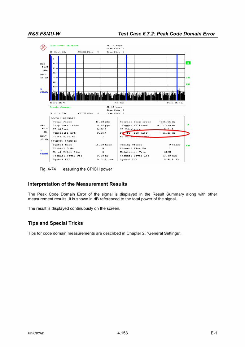
R&S FSMU-W Test Case 6.7.2: Peak Code Domain Error
unknown 4.153 E-1
Fig. 4-74 easuring the CPICH power
Interpretation of the Measurement Results
The Peak Code Domain Error of the signal is displayed in the Result Summary along with other measurement results. It is shown in dB referenced to the total power of the signal. The result is displayed continuously on the screen. Tips and Special Tricks
Tips for code domain measurements are described in Chapter 2, “General Settings”.

Test Case 6.7.2: Peak Code Domain Error R&S FSMU-W
unknown 4.154 E-1
Sample Program
Note: All of the procedures with a name that begins with “Fsmu_” are described in Chapter 2, section “General Routines”.
/*************************************************************************/ void MeasurePeakCodeDomainError (void) /************************************************************************** * measures the peak code domain error of the BTS * **************************************************************************/ { /* -------------------- variables ------------------------------------ */ /* ------ change the following variables according to your needs ----- */ double frequency = 2.14 ; /* GHz */ int scrambling_code = 0x0 ; /* scrambling code in hex */ /* -------------- leave the following variables untouched ----------- */ /* -------------- variables for GPIB bus ----------------------------- */ char ib_string [1000] ; /* strings written to gpib bus */ int analyzer ; /* GPIB handle for Analyzer */ int status ; /* of service register */ /* ----------------- calculation and result display ------------------ */ char result_string [1000] ; /* strings read in from gpib bus */ Fsq_ResultSummary result_summary ; /* structure of the results */ int length_of_data ; /* in Bytes, as reported by FSQ */ /* ------------------------------------------------------------------- */ /* ------------------- initialize BTS -------------------------------- */ Fsmu_MessageBox ("*** User Info ***", "Set BTS to Test Model 3, Max Power") ; /* ------------------- initialize FSQ -------------------------------- */ Fsmu_InitFsq(&analyzer) ; Fsmu_SetupInstrumentFsq (analyzer) ; /* ---- Set the instrument to the frequency of the base station ------ */ sprintf (ib_string, ":SENSe1:FREQuency:CENTer %g GHZ", frequency) ; Fsmu_ibWrtln (analyzer, ib_string) ; /* ----- Switch on 3GPP-FDD BTS measurement -------------------------- */ /* this sets the instrument to continous sweep implicitely * * ------------------------------------------------------------------- */ Fsmu_ibWrtln(analyzer, "INSTrument:SELect BWCD") ; /* ------------- set instrument to single sweep ---------------------- */ Fsmu_ibWrtln(analyzer, ":INITiate1:CONTinuous OFF") ; /* --- set instrument to external trigger (opt), offset -100 usec ---- */ /* set trigger to external after switch on code domain power * * measurement, as negative trigger offsets are only allowed in * * zero span */ Fsmu_ibWrtln(analyzer, ":TRIGger1:SEQuence:SOURce EXTernal") ; Fsmu_ibWrtln(analyzer, ":TRIGger:SEQuence:HOLDoff -100us"); /* ----------- Set FSQ to Single or Multi Carrier mode --------------- */ if (Fsmu_GetMultiCarrier ()) Fsmu_ibWrtln (analyzer, "CONFigure:WCDPower:BTS:MCARrier:STATe ON") ; else Fsmu_ibWrtln (analyzer, "CONFigure:WCDPower:BTS:MCARrier:STATe OFF");

R&S FSMU-W Test Case 6.7.2: Peak Code Domain Error
unknown 4.155 E-1
/* ------------ set FSQ to code domain power measurement ------------- */ Fsmu_ibWrtln(analyzer, "CONFigure:WCDPower:MEASurement WCDPower") ; /* ------------------------- set scrambling code --------------------- */ /* %1x prints an integer in hex at least one digit */ sprintf (ib_string, ":SENSe:CDPower:LCODe:VALue #H%1x", scrambling_code) ; Fsmu_ibWrtln(analyzer, ib_string) ; /* ----------------- use auto detection of test model --------------- */ /* (best results in most cases) * * alternatively: use predefined test model 2, 5 or 5 as appropriate * * Fsmu_ibWrtln(analyzer, ":CONFigure:WCDPower:BTS:CTABle:STATe ON") ; * * Fsmu_ibWrtln(analyzer, * ":CONFigure:WCDPower:BTS:CTABle:SELECT '3GB_3'") ; * */ Fsmu_ibWrtln(analyzer, ":CONFigure:WCDPower:BTS:CTABle:STATe OFF") ; /* ------------------ set antenna diversity to antenna OFF------------ */ Fsmu_ibWrtln(analyzer, ":SENSe:CDPower:ANTenna OFF") ; /* ----------switch FSQ into code domain power measurement------------ */ Fsmu_ibWrtln(analyzer, ":CALCulate2:FEED 'XTIM:CDP:ERR:SUMMary'") ; /* ---------------- auto adjust the FSQ settings --------------------- */ /* wait for the command execution * * this needs the external trigger being active too */ Fsmu_ibWrtln(analyzer, ":SENSe:POWer:ACHannel:PRESet:RLEVel;*OPC?") ; Fsmu_ibRd (analyzer, ib_string, sizeof (ib_string)) ; /* ----------------- clear status registers -------------------------- */ Fsmu_ibWrtln (analyzer, "*CLS") ; /* --------- wait for next external trigger and for result ----------- */ Fsmu_ibWrtln (analyzer, "INITiate:IMMediate;*OPC?") ; Fsmu_ibRd (analyzer, ib_string, sizeof (ib_string)) ; /* ---------- status questionable register, indicates sync ----------- */ Fsmu_ibWrtln (analyzer, ":STATus:QUEStionable:SYNC:CONDition?") ; Fsmu_ibRdln (analyzer, ib_string, sizeof (ib_string)) ; status = atoi (ib_string) ; /* ---------------------- NO SYNC if 2nd bit is set ------------------ */ if (status & 0x02) { Fsmu_MessageBox ("*** ERROR ***", "Sync FAILED -- abort") ; Fsmu_CloseFsq (analyzer) ; return ; } /* ----------------------- read in the summary result ---------------- */ /* see evm.c for a detailled information on reading in the result in * other format * ------------------------------------------------------------------- */ Fsmu_ibWrtln (analyzer, ":FORMat REAL,32;:TRACe:DATA? Trace2") ; /* ------------------------- read in '#d' ---------------------------- */ Fsmu_ibRd (analyzer, ib_string, 2) ;
Test Case 6.7.2: Peak Code Domain Error R&S FSMU-W
unknown 4.156 E-1
/* ------------ skip the '#', get length of next field --------------- */ length_of_data = ib_string [1] - '0' ; /* ------------------------ read in 'lll'; length -------------------- */ Fsmu_ibRd (analyzer, ib_string, length_of_data) ; ib_string [length_of_data] = '\0' ; length_of_data = atoi (ib_string) ; /* -------------------------- read in the data ----------------------- */ Fsmu_ibRd (analyzer, (char *)&result_summary, length_of_data) ; /* ------------------- read in trailing LF from FSQ ------------------ */ Fsmu_ibRd (analyzer, ib_string, 1) ; /* --------------------- display the result -------------------------- */ sprintf (result_string , "Peak code domain error: %7.2f dB\n", result_summary.peak_domain_error) ; Fsmu_MessageBox ("*** Result ***", result_string) ; /* --------------------- close FSQ on GPIB --------------------------- */ Fsmu_CloseFsq (analyzer) ; }

R&S FSMU-W Receiver Test Cases
1166.1560.12 4.157 E-1
Receiver Test Cases
Test Case 7.2: Reference Sensitivity Level
Test Purpose
The test case shall verify that a BS receiver has the capability to demodulate the signal that is sent by the SMU at the specified (low) reference sensitivity power level, properly. The test is passed when the resulting BER (calculated internally by the BS) is below a specified thresh-old at the test frequencies B, M, and T. Quotation from [1]:
The reference sensitivity level is the minimum mean power received at the antenna connector at which the BER shall not exceed the specific value indicated in subclause 7.2.2. The test is set up according to Figure B.7 and performed without interfering signal power applied to the BS antenna connector. For duplex operation, the measurement configuration principle is indicated for one du-plex branch in Figure B.7. For internal BER calculation an example of the test connection is as shown in figure B.7. The reference point for signal power is at the input of the receiver (antenna connector).
Test Setup
The test setup pictured in Fig. 4-72 is suitable to measure the base station reference sensitivity.
Fig. 4-72 Test Setup according to TS 25.141 for Baseband A Signal Routing to RF Port A
For routing baseband A signal to RF port A this port is connected to the base station Rx port. The SMU will start signal generation by the first BS frame trigger sent to trigger port Trigger 1. Recommended Options
The basic configuration (R&S FSMU3-W, R&S FSMU8-W or R&S FSMU26-W) is sufficient to set up the R&S SMU completely.

Receiver Test Cases R&S FSMU-W
1166.1560.12 4.158 E-1
Test Case Wizard Panel
The Fig. 4-73 and Fig. 4-74 show the input parameters for both kinds of Edit Modes ‘According to Standard’ and ‘User Definable’.
Fig. 4-73 Test case panel for ‘According to Standard’
Fig. 4-74 Test case panel for ‘User Definable’

R&S FSMU-W Receiver Test Cases
1166.1560.12 4.159 E-1
The input/ouput parameters of the wizard panel read as follows: Wanted Signal State Enables/Disables the signal generation of the wanted 3GPP signal. In
case of ‘According to Standard’ the state is fixed to ‘On’. In case of ‘User Definable’ the user may switch ‘Off’ the state. Remote-control command: :SOUR:BB:W3GP:TS25141:WSIGnal:STATe [ON | OFF]
Reference Measurement Channel
Sets the reference measurement channel. The user can choose from: • RMC 12.2 kbps: 12.2 kbps measurement channel • RMC 64 kbps: 64 kbps measurement channel • RMC 144 kbps: 144 kbps measurement channel • RMC 384 kbps: 384 kbps measurement channel • AMR 12.2 kbps: channel coding for the AMR coder In case of ‘According to Standard’ the choice is fixed to RMC 12.2 kbps. Remote-control command: :SOUR:BB:W3GP:TS25141:WSIGnal:DPDCh:CCODing:TYPE [M12K2 | M64K | M144k | M384k | AMR]
RF Frequency Sets the RF frequency of the wanted signal. Remote-control command: :SOUR:BB:W3GP:TS25141:WSIGnal:FREQ [100.0 KHz .. 6.0 GHz]
Power Level (read only in case of ‚According to Standard’)
Displays the RF power level of the wanted signal in case of ‘According to Standard’: • -120.3 dB when Wide Area BS • -110.3 dB when Medium Range BS • -106.3 dB when Local Area BS In case of ‘User Definable’ the user can enter an arbitrary power level figure. Remote-control command: :SOUR:BB:W3GP:TS25141:WSIGnal:POW [-145.0 dBm .. 20.0 dBm]

Receiver Test Cases R&S FSMU-W
1166.1560.12 4.160 E-1
Fig. 4-75 Routing of baseband A to RF port A
Fig. 4-75 shows an achieved example signal flow within the SMU after pressing the Apply Settings button. In case of routing to path A/B the RF port A/B holds a reference measurement channel signal. The test setup pictured in Fig. 4-76 is suitable to measure the base station reference sensitivity.
BS
RXA orRXA/TX
RXB
BER (optional)
BER
(if needed)
RF signal source or UE simulator RF out
Termination (if needed)
Fig. 4-76 Test Setup according to TS 25.141 for Baseband A Signal Routing to RF Port A

R&S FSMU-W Receiver Test Cases
1166.1560.12 4.161 E-1
Variation in the Parameters of the Base Station
The measurement must be made at the three frequencies B, M and T. Structure of the Measurement
The following diagram illustrates the structure of a measurement: Note: The measurement must be made at frequencies B, M and T. This is represented in the
diagram using f={B,M,T}.
7.2 ReferenceSensitivity Level
Init BTS
Set BTS to f
Set SMU TestCase Wizard
Trigger SMU
Measure BER
next f
f > last freq?n
y
f={B,M,T}
Set BTS toRMC 12.2
kbps
Set BTS todisabled TPC
function
Init SMU
Fig. 4-77 Structure of the "Reference Sensitivity Level” measurement

Receiver Test Cases R&S FSMU-W
1166.1560.12 4.162 E-1
Settings on the Base Station
The following table lists the settings to make on the base station: Parameter Value
Frequency B, M and T
RMC 12.2 kbps
Scrambling code Any
TPC function OFF
Set the frequency to B, M and T during the course of the measurements. Steps for Carrying Out a Measurement
1. Set the BTS to the basic state Initialize the BTS, Set the scrambling scheme, Set the BTS to receive the Reference Measurement Channel 12.2 kbps, Switch off the TPC function, Set the frequency, for example, to M.
2. Set the SMU to the basic state Initialize the SMU by pressing the the PRESET key unless some settings (e.g. in terms of I/Q and RF blocks) have to be kept.
3. Set the test case wizard
Press Test Case and select Test Case 7.2. The panel adapts to its test case.
Press Edit Mode and select According to Standard. This selection guides the user close to TS 25.141.
Press Trigger Configuration and select Auto. This selection applies to this measurement description.
Press Marker Configuration and select Auto. This selection applies to this measurement description.
Press Baseband A Signal Routing and select which RF output port (A or B) is connected to the BTS. Enter Scrambling Code, Scrambling Mode according to the BTS scrambling scheme. Enter the Power Class of the BTS under test. Press RF Frequency and enter the same frequency (e.g. M) the BTS has set to. Press Apply Settings.
The SMU is now ready to start signal generation.
4. Start the measurement Send a start trigger impulse (e.g. SFN modulo 4 from the BTS) to the SMU.
The SMU will start signal generation.
5. Calculate the result The BTS internally calculates the BER.

R&S FSMU-W Receiver Test Cases
1166.1560.12 4.163 E-1
Interpretation of the Measurement Results
The internally calculated BER shall not exceed 0.001. Note TS 25.141 Annex C: General Rules for Sta-tistical Testing, where test conditions in terms of test methods and test conditions are defined. Tips and Special Tricks
Ensure that the RF blocks are switched on while the measurement procedure is running. Since the test case wizard does not activate or deactivate the RF ports, these have to be switched on before or after the Apply Settings button is pressed. The signal quality can be enhanced or for test purposes modified by additional settings in the impair-ments section of the AWGN block, in the I/Q modulator block and in the RF block. Usually the test case wizard does not alter these settings. In case of an channel coded signal, e.g. an RMC is activated, the base station that triggers the SMU signal generation shall emit an ‘SFN (System Frame Number) mod 4’ periodic trigger. A simple SFN periodic trigger probably will disturb the channel coding scheme. Sample Program
Note: All of the procedures with a name that begins with "Fsmu_" are described in Chapter 6, section "General Routines".
/* ************************************************************************ * Module: ReferenceSensitivityLevel.c * Copyright: (c) 2004, Rohde & Schwarz GmbH & Co KG * Project: FSMU * Description measures the reference sensitivity level * according to test case 7.2 * * ***********************************************************************/ #ifdef _CVI_ /* this is needed by Labwindows / CVI compiler only */ #include <ansi_c.h> #else /* ANSI-C compilers */ #include <stdlib.h> /* atoi */ #include <stdio.h> /* sprintf */ #include <string.h> /* strcat, strlen */ #endif #include "fsmu_global.h" #include "3gpp_tests.h" /* ------------------------- local structures ------------------------- */ /*************************************************************************/ void MeasureReferenceSensitivityLevel (void) /************************************************************************* * measures the reference sensitivity level * **************************************************************************/ { /* -------------------- variables ------------------------------------ */ /* ------ change the following variables according to your needs ----- */

Receiver Test Cases R&S FSMU-W
1166.1560.12 4.164 E-1
double dl_frequency = 2.14 ; /* GHz, of transmitter */ double dl_ul_duplex =-0.19 ; /* GHz, receiver freq is lower */ int ue_scrambling_code = 0x00 ; /* scrambling code of UE in hex */ /* used for simulation only */ int bts_scrambling_code = 0x0 ; /* scrambling code of BTS in hex */ int smu_trigger_delay = 0 ; /* frame-trigger to SMU in chips */ /* -------------- leave the following variables untouched ----------- */ /* -------------- variables for GPIB bus ----------------------------- */ char ib_string [1000] ; /* strings written to gpib bus */ int analyzer ; /* GPIB handle for Analyzer */ int generator ; /* GPIB handle for Generator */ int status ; /* of service register */ int SaveTimeOut ; /* save value, when changine device's * * default time out via ibtmo */ /* ----------------- calculation and result ------------------------- */ char result_string [10000] ; /* ascii string of result message */ #ifdef CRTU dl_frequency = 0.01536 ; /* GHz, of transmitter */ dl_ul_duplex = -0.00768 ; /* GHz, receiver freq is lower */ uplink_level = -20.0; /* dBm */ smu_trigger_delay = 38380; /* chips */ #endif /* ------------------------------------------------------------------- */ /* =================================================================== */ /* ====================== REFERENCE SENSITIVITY LEVEL ================ */ /* =================================================================== */ /* ------------ Steps for Carrying Out a Measurement ----------------- */ /* ------------ 1. Set the BTS to the basic state -------------------- */ Fsmu_MessageBox ("*** User Info ***", "Initialize the BTS,\n" "Set the scrambling scheme,\n" "Set the BTS to receive the Reference Measurement Channel 12.2 kbps,\n" "Switch off the TPC function,\n" "Set the frequency, for example, to M,\n" "Connect frame trigger of BTS to SMU Trigger 1") ; /* ------------ 2. Set the SMU to the basic state -------------------- */ /* Initialize the SMU by pressing the the PRESET key ----------------- */ Fsmu_InitSmu (&generator); Fsmu_ibWrtln (generator, "*RST") ; #if 0 /* ------------ Trigger slope: POSitive or NEGative ------------------ */ Fsmu_ibWrtln (generator, ":INPut:TRIGger:BBANd:SLOPe POSitive") ; // Fsmu_ibWrtln (generator, ":INPut:TRIGger:BBANd:SLOPe NEGative") ; #endif /* ------------ Switch on the generator, RF channel A only ----------- */ Fsmu_ibWrtln(generator, ":OUTPut1:STATe ON") ; Fsmu_DeviceCheckSystemErrors(generator) ; /* ------------ 3. Set the test case wizard -------------------------- */

R&S FSMU-W Receiver Test Cases
1166.1560.12 4.165 E-1
/* ------------ Enter Test Case: Test Case 7.2. ---------------------- */ Fsmu_ibWrtln (generator, ":SOUR:BB:W3GP:TS25141:TCASe TC72") ; /* ------------ Set Edit Mode to According to Standard. -------------- */ Fsmu_ibWrtln (generator, ":SOUR:BB:W3GP:TS25141:EMODe STANdard") ; /* ------------ Set Trigger Configuration and select Auto. ----------- */ Fsmu_ibWrtln (generator, ":SOUR:BB:W3GP:TS25141:TRIGger AUTO") ; /* ------------ Set Marker Configuration and select Auto. ------------ */ Fsmu_ibWrtln (generator, ":SOUR:BB:W3GP:TS25141:TRIGger:OUTPut AUTO") ; /* ------------ Set Baseband A Signal Routing to RF output port A. --- */ Fsmu_ibWrtln (generator, ":SOUR:BB:W3GP:TS25141:ROUTe A") ; /* ------------ Enter Scrambling Code, Scrambling Mode --------------- */ /* %1x prints an integer in hex at least one digit ------------------- */ sprintf (ib_string, ":SOUR:BB:W3GP:TS25141:SCODe %1x", ue_scrambling_code) ; Fsmu_ibWrtln(generator, ib_string) ; Fsmu_ibWrtln(generator, ":SOUR:BB:W3GP:TS25141:SCODe:MODE LONG") ; /* ------------ Enter the Power Class of the BTS under test. --------- */ Fsmu_ibWrtln (generator, "SOUR:BB:W3GP:TS25141:BSPClass WIDE") ; /* ------------ Enter RF Frequency ----------------------------------- */ /* Set SMU to the UL frequency of the base station ------------------- */ sprintf (ib_string, ":SOUR:BB:W3GP:TS25141:WSIGnal:FREQ %g GHz", dl_frequency + dl_ul_duplex) ; Fsmu_ibWrtln (generator, ib_string) ; /* ------------ Press Apply Settings. -------------------------------- */ /* This may take a long time, so set time out temporarily to 100 sec - */ Fsmu_ibGetTmo(generator, &SaveTimeOut) ; Fsmu_ibTmo (generator, T100s) ; Fsmu_ibWrtln (generator, ":SOUR:BB:W3GP:TS25141:TCASe:EXECute") ; Fsmu_WaitForDevice(generator); // Fsmu_ibWrtln(generator, "*OPC?"); Fsmu_ibRd (generator, ib_string, sizeof (ib_string)) ; Fsmu_ibTmo (generator, SaveTimeOut) ; /* ------- Examples of SMU settings after the test case wizards ------ */ #if 0 /* ------- input trigger delay: only positive values are allowed ----- */ sprintf (ib_string, ":BB:W3GP:TRIGger:EXTernal:DELay %d", smu_trigger_delay) ; Fsmu_ibWrtln (generator, ib_string) ; /* -------------- adjust output power to 0 dB ------------------------ */ Fsmu_ibWrtln(generator, ":BB:W3GPp:POWer:ADJust") ; /* ------------------ Stop SMU to get defined timing ----------------- */ Fsmu_ibWrtln (generator, ":BB:W3GPp:TRIGger:ARM:EXECute;*OPC?") ; Fsmu_ibRd (generator, ib_string, sizeof (ib_string)) ; /* -------- adjust output power to 0 dB and wait for execution ------- */ Fsmu_ibWrtln(generator, ":BB:W3GPp:POWer:ADJust;*OPC?") ; Fsmu_ibRd (generator, ib_string, sizeof (ib_string)) ; /* ------------- enable external trigger in SMU ---------------------- */ if (!Fsmu_GetBtsEmulation()) { Fsmu_ibWrtln (generator, ":BB:W3GP:TRIGger:SOURce EXTernal;*OPC?") ; Fsmu_ibRd (generator, ib_string, sizeof (ib_string)) ; } else

Receiver Test Cases R&S FSMU-W
1166.1560.12 4.166 E-1
{ Fsmu_ibWrtln (generator, ":BB:W3GP:TRIGger:EXECute;*OPC?") ; Fsmu_ibRd (generator, ib_string, sizeof (ib_string)) ; } #endif /* ------------------------------------------------------------------- */ /* ------------ The SMU is now ready to start signal generation ------ */ /* ------------------------------------------------------------------- */ /* ------------ 4. Start the measurement ----------------------------- */ /* Send a start trigger impulse to the SMU. -------------------------- */ /* The SMU will start signal generation. ------------------------------*/ /* ------------ 5. Calculate the result ------------------------------ */ /* The BTS internally calculates the BER. ---------------------------- */ #ifdef FSMU_LOG_DATA /* ------------------------------------------------------------------- */ /* ------------ Write output data file; --------------- */ /* ------------------------------------------------------------------- */ { FILE * myfile ; myfile = fopen ("reference_sensitivity_level.dat", "w") ; if (myfile) { fprintf (myfile, " This is a data file created while reference sensitivity level measurements"); fclose (myfile) ; } } #endif /* ----------- Display the result ------------------------------------*/ sprintf (result_string , "----------------------------------------\n" " reference sensitivity level\n" "------------ -------------\n"); Fsmu_MessageBox ("*** Result ***", result_string) ; /* --------------------- Close SMU on GPIB --------------------------- */ Fsmu_CloseSmu (generator) ; }

R&S FSMU-W Receiver Test Cases
1166.1560.12 4.167 E-1
Test Case 7.3: Dynamic Range
Test Purpose
The test case shall verify that a BS receiver has the capability to demodulate the signal that is sent by the SMU but superimposed by a heavy AWGN. The test is passed when the resulting BER (calculated internally by the BS) is below a specified thresh-old at the test frequencies B, M, and T. Quotation from [1]:
Receiver dynamic range is the receiver ability to handle a rise of interference in the reception fre-quency channel. The receiver shall fulfil a specified BER requirement for a specified sensitivity degradation of the wanted signal in the presence of an interfering AWGN signal in the same re-ception frequency channel.
Test Setup
The test setup pictured in Fig. 4-78 is suitable to measure the base station dynamic range.
Fig. 4-78 Test Setup according to TS 25.141 for Baseband A Signal Routing to RF Port A
For routing baseband A signal to RF port A this port is connected to the base station Rx port. The SMU will start signal generation by the first BS frame trigger sent to trigger port Trigger 1. Recommended Options
The basic configuration (R&S FSMU3-W, R&S FSMU8-W or R&S FSMU26-W) is sufficient to set up the R&S SMU completely, which includes the option R&S SMU-B62: Additional White Gaussian Noise (AWGN) that is required to set up the SMU.

Receiver Test Cases R&S FSMU-W
1166.1560.12 4.168 E-1
Test Case Wizard Panel
The Fig. 4-79 and Fig. 4-80 show the input parameters for both kinds of Edit Modes ‘According to Standard’ and ‘User Definable’.
Fig. 4-79 Test case panel for ‘According to Standard’
Fig. 4-80 Test case panel for ‘User Definable’

R&S FSMU-W Receiver Test Cases
1166.1560.12 4.169 E-1
The input/ouput parameters of the wizard panel read as follows: Wanted Signal State Enables/Disables the signal generation of the wanted 3GPP signal. In
case of ‘According to Standard’ the state is fixed to ‘On’. In case of ‘User Definable’ the user may switch ‘Off’ the state. Remote-control command: :SOUR:BB:W3GP:TS25141:WSIGnal:STATe [ON | OFF]
Reference Measurement Channel
Sets the reference measurement channel. The user can choose from: • RMC 12.2 kbps: 12.2 kbps measurement channel • RMC 64 kbps: 64 kbps measurement channel • RMC 144 kbps: 144 kbps measurement channel • RMC 384 kbps: 384 kbps measurement channel • AMR 12.2 kbps: channel coding for the AMR coder In case of ‘According to Standard’ the choice is fixed to RMC 12.2 kbps. Remote-control command: :SOUR:BB:W3GP:TS25141:WSIGnal:DPDCh:CCODing:TYPE [M12K2 | M64K | M144k | M384k | AMR]
RF Frequency Sets the RF frequency of the wanted signal. Remote-control command: :SOUR:BB:W3GP:TS25141:WSIGnal:FREQ [100.0 KHz .. 6.0 GHz]
Power Level (read only in case of ‚According to Stan-dard’)
Displays the RF power level of the wanted signal in case of ‘Accord-ing to Standard’: • -89.8 dBm whenWide Area BS • -79.8 dBm when Medium Range BS • -75.8 dBm when Local Area BS In case of ‘User Definable’ the user can enter an arbitrary power level of the wanted signal. Remote-control command: :SOUR:BB:W3GP:TS25141:WSIGnal:POW [-145.0 dBm .. 20.0 dBm]
AWGN State Enables/Disables the signal generation of the AWGN. In case of ‘Ac-cording to Standard’ the state is fixed to ‘On’. In case of ‘User De-finable’ the user may switch ‘Off’ the state. Remote-control command: :SOUR:BB:W3GP:TS25141:AWGN:STATe [ON | OFF]
C/N Sets the power ratio of wanted signal versus AWGN power. In case of ‘According to Standard’ the ratio is fixed to -16.8 dB. In case of ‘User Definable’ the user can enter an arbitrary power level of the wanted signal. Remote-control command: :SOUR:BB:W3GP:TS25141:AWGN:CNRatio [-80.0 dB .. 80.0 dB]
Power Level (within 3.84 MHz BW) (read only in case of ‚According to Standard’)
Displays the AWGN power level in case of ‘According to Standard’: • -73 dBm when Wide Area BS • -63 dBm when Medium Range BS • -59 dBm when Local Area BS In case of ‘User Definable’ the user can enter an arbitrary power level. Remote-control command: :SOUR:BB:W3GP:TS25141:AWGN:POW:NOISe

Receiver Test Cases R&S FSMU-W
1166.1560.12 4.170 E-1
Fig. 4-81 and Fig. 4-82 show an achieved example signal flow within the SMU after pressing the Apply Set-tings button.
Fig. 4-81 Routing of baseband A to RF port A
Fig. 4-82 Routing of baseband A to RF port B
In case of routing to path A/B the RF port A/B holds a reference measurement channel signal disturbed by an interfer-ing AWGN signal. The test setup pictured in Fig. 4-83 is suitable to measure the base station dynamic range.

R&S FSMU-W Receiver Test Cases
1166.1560.12 4.171 E-1
Fig. 4-83 Test Setup according to TS 25.141 for Baseband A Signal Routing to RF Port A
Variation in the Parameters of the Base Station
The measurement must be made at the three frequencies B, M and T. Structure of the Measurement
The following diagram illustrates the structure of a measurement: Note: The measurement must be made at frequencies B, M and T. This is represented in the
diagram using f={B,M,T}.
7.3 DynamicRange
Init BTS
Set BTS to f
Set SMU TestCase Wizard
Trigger SMU
Measure BER
next f
f > last freq?n
y
f={B,M,T}
Set BTS toRMC 12.2
kbps
Init SMU
Fig. 4-84 Structure of the "Dynamic Range” measurement

Receiver Test Cases R&S FSMU-W
1166.1560.12 4.172 E-1
Settings on the Base Station
The following table lists the settings to make on the base station: Parameter Value
Frequency B, M and T
RMC 12.2 kbps
Scrambling code Any
Set the frequency to B, M and T during the course of the measurements. Steps for Carrying Out a Measurement
1. Set the BTS to the basic state Initialize the BTS, Set the scrambling scheme, Set the BTS to receive the Reference Measurement Channel 12.2 kbps, Set the frequency, for example, to M.
2. Set the SMU to the basic state Initialize the SMU by pressing the the PRESET key unless some settings (e.g. in terms of I/Q and RF blocks) have to be kept.
3. Set the test case wizard Press Test Case and select Test Case 7.3.
The panel adapts to its test case. Press Edit Mode and select According to Standard.
This selection guides the user close to TS 25.141. Press Trigger Configuration and select Auto.
This selection applies to this measurement description. Press Marker Configuration and select Auto.
This selection applies to this measurement description. Press Baseband A Signal Routing and select which RF output port (A or B) is connected to the BTS. Enter Scrambling Code, Scrambling Mode according to the BTS scrambling scheme. Enter the Power Class of the BTS under test. Press RF Frequency and enter the same frequency (e.g. M) the BTS has set to. Press Apply Settings.
The SMU is now ready to start signal generation.
4. Start the measurement Send a start trigger impulse (e.g. SFN modulo 4 from the BTS) to the SMU.
The SMU will start signal generation.
5. Calculate the result The BTS internally calculates the BER.
Interpretation of the Measurement Results
The internally calculated BER shall not exceed 0.001. Note TS 25.141 Annex C: General Rules for Sta-tistical Testing, where test conditions in terms of test methods and test conditions are defined.

R&S FSMU-W Receiver Test Cases
1166.1560.12 4.173 E-1
Tips and Special Tricks
Ensure that the RF blocks are switched on while the measurement procedure is running. Since the test case wizard does not activate or deactivate the RF ports, these have to be switched on before or after the Apply Settings button is pressed. The signal quality can be enhanced or for test purposes modified by additional settings in the impair-ments section of the AWGN block, in the I/Q modulator block and in the RF block. Usually the test case wizard does not alter these settings. In case of an channel coded signal, e.g. an RMC is activated, the base station that triggers the SMU signal generation shall emit an ‘SFN (System Frame Number) mod 4’ periodic trigger. A simple SFN periodic trigger probably will disturb the channel coding scheme. Sample Program
Note: All of the procedures with a name that begins with "Fsmu_" are described in Chapter 6, section "General Routines".
/* ************************************************************************ * Module: DynamicRange.c * Copyright: (c) 2004, Rohde & Schwarz GmbH & Co KG * Project: FSMU * Description measures the dynamic range * according to test case 7.3 * * ***********************************************************************/ #ifdef _CVI_ /* this is needed by Labwindows / CVI compiler only */ #include <ansi_c.h> #else /* ANSI-C compilers */ #include <stdlib.h> /* atoi */ #include <stdio.h> /* sprintf */ #include <string.h> /* strcat, strlen */ #endif #include "fsmu_global.h" #include "3gpp_tests.h" /* ------------------------- local structures ------------------------- */ /*************************************************************************/ void MeasureDynamicRange (void) /************************************************************************* * measures the dynamic range * **************************************************************************/ { /* -------------------- variables ------------------------------------ */ /* ------ change the following variables according to your needs ----- */ double dl_frequency = 2.14 ; /* GHz, of transmitter */ double dl_ul_duplex =-0.19 ; /* GHz, receiver freq is lower */ int ue_scrambling_code = 0x00 ; /* scrambling code of UE in hex */ /* used for simulation only */ int bts_scrambling_code = 0x0 ; /* scrambling code of BTS in hex */ int smu_trigger_delay = 0 ; /* frame-trigger to SMU in chips */ /* -------------- leave the following variables untouched ----------- */

Receiver Test Cases R&S FSMU-W
1166.1560.12 4.174 E-1
/* -------------- variables for GPIB bus ----------------------------- */ char ib_string [1000] ; /* strings written to gpib bus */ int analyzer ; /* GPIB handle for Analyzer */ int generator ; /* GPIB handle for Generator */ int status ; /* of service register */ int SaveTimeOut ; /* save value, when changine device's * * default time out via ibtmo */ /* ----------------- calculation and result ------------------------- */ char result_string [10000] ; /* ascii string of result message */ #ifdef CRTU dl_frequency = 0.01536 ; /* GHz, of transmitter */ dl_ul_duplex = -0.00768 ; /* GHz, receiver freq is lower */ uplink_level = -20.0; /* dBm */ smu_trigger_delay = 38380; /* chips */ #endif /* ------------------------------------------------------------------- */ /* =================================================================== */ /* ====================== DYNAMIC RANGE ============================== */ /* =================================================================== */ /* ------------ Steps for Carrying Out a Measurement ----------------- */ /* ------------ 1. Set the BTS to the basic state -------------------- */ Fsmu_MessageBox ("*** User Info ***", "Initialize the BTS,\n" "Set the scrambling scheme,\n" "Set the BTS to receive the Reference Measurement Channel 12.2 kbps,\n" "Set the frequency, for example, to M,\n" "Connect frame trigger of BTS to SMU Trigger 1") ; /* ------------ 2. Set the SMU to the basic state -------------------- */ /* Initialize the SMU by pressing the the PRESET key ----------------- */ Fsmu_InitSmu (&generator); Fsmu_ibWrtln (generator, "*RST") ; #if 0 /* ------------ Trigger slope: POSitive or NEGative ------------------ */ Fsmu_ibWrtln (generator, ":INPut:TRIGger:BBANd:SLOPe POSitive") ; // Fsmu_ibWrtln (generator, ":INPut:TRIGger:BBANd:SLOPe NEGative") ; #endif /* ------------ Switch on the generator, RF channel B only ----------- */ Fsmu_ibWrtln(generator, ":OUTPut2:STATe ON") ; Fsmu_DeviceCheckSystemErrors(generator) ; /* ------------ 3. Set the test case wizard -------------------------- */ /* ------------ Enter Test Case: Test Case 7.3. ---------------------- */ Fsmu_ibWrtln (generator, ":SOUR:BB:W3GP:TS25141:TCASe TC73") ; /* ------------ Set Edit Mode to According to Standard. -------------- */ Fsmu_ibWrtln (generator, ":SOUR:BB:W3GP:TS25141:EMODe STANdard") ; /* ------------ Set Trigger Configuration and select Auto. ----------- */ Fsmu_ibWrtln (generator, ":SOUR:BB:W3GP:TS25141:TRIGger AUTO") ;

R&S FSMU-W Receiver Test Cases
1166.1560.12 4.175 E-1
/* ------------ Set Marker Configuration and select Auto. ------------ */ Fsmu_ibWrtln (generator, ":SOUR:BB:W3GP:TS25141:TRIGger:OUTPut AUTO") ; /* ------------ Set Baseband A Signal Routing to RF output port B. --- */ Fsmu_ibWrtln (generator, ":SOUR:BB:W3GP:TS25141:ROUTe B") ; /* ------------ Enter Scrambling Code, Scrambling Mode --------------- */ /* %1x prints an integer in hex at least one digit ------------------- */ sprintf (ib_string, ":SOUR:BB:W3GP:TS25141:SCODe %1x", ue_scrambling_code) ; Fsmu_ibWrtln(generator, ib_string) ; Fsmu_ibWrtln(generator, ":SOUR:BB:W3GP:TS25141:SCODe:MODE LONG") ; /* ------------ Enter the Power Class of the BTS under test. --------- */ Fsmu_ibWrtln (generator, ":SOUR:BB:W3GP:TS25141:BSPClass MEDium") ; /* ------------ Enter RF Frequency ----------------------------------- */ /* Set SMU to the UL frequency of the base station ------------------- */ sprintf (ib_string, ":SOUR:BB:W3GP:TS25141:WSIGnal:FREQ %g GHz", dl_frequency + dl_ul_duplex) ; Fsmu_ibWrtln (generator, ib_string) ; /* ------------ Press Apply Settings. -------------------------------- */ /* This may take a long time, so set time out temporarily to 100 sec - */ Fsmu_ibGetTmo(generator, &SaveTimeOut) ; Fsmu_ibTmo (generator, T100s) ; Fsmu_ibWrtln (generator, ":SOUR:BB:W3GP:TS25141:TCASe:EXECute") ; Fsmu_WaitForDevice(generator); // Fsmu_ibWrtln(generator, "*OPC?"); Fsmu_ibRd (generator, ib_string, sizeof (ib_string)) ; Fsmu_ibTmo (generator, SaveTimeOut) ; /* ------- Examples of SMU settings after the test case wizards ------ */ #if 0 /* ------- input trigger delay: only positive values are allowed ----- */ sprintf (ib_string, ":BB:W3GP:TRIGger:EXTernal:DELay %d", smu_trigger_delay) ; Fsmu_ibWrtln (generator, ib_string) ; /* -------------- adjust output power to 0 dB ------------------------ */ Fsmu_ibWrtln(generator, ":BB:W3GPp:POWer:ADJust") ; /* ------------------ Stop SMU to get defined timing ----------------- */ Fsmu_ibWrtln (generator, ":BB:W3GPp:TRIGger:ARM:EXECute;*OPC?") ; Fsmu_ibRd (generator, ib_string, sizeof (ib_string)) ; /* -------- adjust output power to 0 dB and wait for execution ------- */ Fsmu_ibWrtln(generator, ":BB:W3GPp:POWer:ADJust;*OPC?") ; Fsmu_ibRd (generator, ib_string, sizeof (ib_string)) ; /* ------------- enable external trigger in SMU ---------------------- */ if (!Fsmu_GetBtsEmulation()) { Fsmu_ibWrtln (generator, ":BB:W3GP:TRIGger:SOURce EXTernal;*OPC?") ; Fsmu_ibRd (generator, ib_string, sizeof (ib_string)) ; } else { Fsmu_ibWrtln (generator, ":BB:W3GP:TRIGger:EXECute;*OPC?") ; Fsmu_ibRd (generator, ib_string, sizeof (ib_string)) ; } #endif /* ------------------------------------------------------------------- */

Receiver Test Cases R&S FSMU-W
1166.1560.12 4.176 E-1
/* ------------ The SMU is now ready to start signal generation ------ */ /* ------------------------------------------------------------------- */ /* ------------ 4. Start the measurement ----------------------------- */ /* Send a start trigger impulse to the SMU. -------------------------- */ /* The SMU will start signal generation. ------------------------------*/ /* ------------ 5. Calculate the result ------------------------------ */ /* The BTS internally calculates the BER. ---------------------------- */ #ifdef FSMU_LOG_DATA /* ------------------------------------------------------------------- */ /* ------------ Write output data file; --------------- */ /* ------------------------------------------------------------------- */ { FILE * myfile ; myfile = fopen ("dynamic_range.dat", "w") ; if (myfile) { fprintf (myfile, " This is a data file"); fclose (myfile) ; } } #endif /* ----------- Display the result ------------------------------------*/ sprintf (result_string , "----------------------------------------\n" " dynamic range\n" "------------ -------------\n"); Fsmu_MessageBox ("*** Result ***", result_string) ; /* --------------------- Close SMU on GPIB --------------------------- */ Fsmu_CloseSmu (generator) ; }

R&S FSMU-W Receiver Test Cases
1166.1560.12 4.177 E-1
Test Case 7.4: Adjacent Channel Selectivity
Test Purpose
The test case shall verify that a BS receiver has the capability to demodulate a signal that is sent by the SMU but superimposed by a heavy WCDMA signal in the adjacent channel. The test is passed when the resulting BER (calculated internally by the BS) is below a specified thresh-old at the test frequencies B, M, and T. Quotation from [1]:
Adjacent channel selectivity (ACS) is a measure of the receiver ability to receive a wanted signal at is assigned channel frequency in the presence of an adjacent channel signal at a given fre-quency offset from the center frequency of the assigned channel. ACS is the ratio of the receiver filter attenuation on the assigned channel frequency to the receive filter attenuation on the adja-cent channel(s). The interference signal is offset from the wanted signal by the frequency offset Fuw. The interfer-ence signal shall be a W-CDMA signal as specified in Annex I.
Test Setup
The test setup pictured in Fig. 4-85 is suitable to measure the base station adjacent channel selectivity.
Fig. 4-85 Test Setup according to TS 25.141 for Baseband A Signal Routing to RF Port A
For routing baseband A signal to RF port A this port holds the wanted signal, whereas RF port B holds the infering signal. After combining the sum is fed into the base station Rx port. The SMU will start sig-nal generation by the first BS frame trigger sent to trigger port Trigger 1. Recommended Options
Besides the basic configuration (R&SFSMU3-W, R&SFSMU8-W or R&SFSMU26-W) the options
• R&SFSMU-B1 (consisting of R&S SMU-B203 2nd RF path (3.0 GHz), R&S SMU-B13 Baseband main module, R&S SMU-K62 Additive white Gaussian noise, R&S SMU-B36 High output power) and
• R&SFSMU-B2 (consisting of R&S SMU-B11 Baseband generator, R&S SMU-K42 Digital standard 3GPP FDD, R&S SMU-K43 Enhanced BS tests for 3GPP FDD incl. HSDPA)
are required to set up the R&S SMU.

Receiver Test Cases R&S FSMU-W
1166.1560.12 4.178 E-1
Test Case Wizard Panel
The Fig. 4-86 and Fig. 4-87 show the input parameters for both kinds of Edit Modes ‘According to Standard’ and ‘User Definable’.
Fig. 4-86 Test case panel for ‘According to Standard’

R&S FSMU-W Receiver Test Cases
1166.1560.12 4.179 E-1
Fig. 4-87 Test case panel for ‘User Definable’
The input/ouput parameters of the wizard panel read as follows: Wanted Signal State Enables/Disables the signal generation of the wanted 3GPP signal. In
case of ‘According to Standard’ the state is fixed to ‘On’. In case of ‘User Definable’ the user may switch ‘Off’ the state. Remote-control command: :SOUR:BB:W3GP:TS25141:WSIGnal:STATe [ON | OFF]
Reference Measurement Channel
Sets the reference measurement channel. The user can choose from: • RMC 12.2 kbps: 12.2 kbps measurement channel • RMC 64 kbps: 64 kbps measurement channel • RMC 144 kbps: 144 kbps measurement channel • RMC 384 kbps: 384 kbps measurement channel • AMR 12.2 kbps: channel coding for the AMR coder In case of ‘According to Standard’ the choice is fixed to RMC 12.2 kbps. Remote-control command: :SOUR:BB:W3GP:TS25141:WSIGnal:DPDCh:CCODing:TYPE [M12K2 | M64K | M144k | M384k | AMR]
RF Frequency Sets the RF frequency of the wanted signal. Remote-control command: :SOUR:BB:W3GP:TS25141:WSIGnal:FREQ [100.0 KHz .. 6.0 GHz]

Receiver Test Cases R&S FSMU-W
1166.1560.12 4.180 E-1
Power Level Displays the RF power level of the wanted signal in case of ‘Accord-
ing to Standard’: • -115 dB when Wide Area BS • -105 dB when Medium Range BS • -101 dB when Local Area BS In case of ‘User Definable’ the user can enter an arbitrary power level figure. Remote-control command: :SOUR:BB:W3GP:TS25141:WSIGnal:POW [-145.0 dBm .. 20.0 dBm]
Interference Signal State Enables/Disables the signal generation of the interference signal (e.g. WCDMA). In case of ‘According to Standard’ the state is fixed to ‘On’. In case of ‘User Definable’ the user may switch ‘Off’ the state. Remote-control command: :SOUR:BB:W3GP:TS25141:IFSignal:STATe [ON | OFF]
Frequency Offset Sets frequency offset of the interference signal versus the wanted signal RF frequency. In case of ‘According to Standard’ the choice is limited to: • +5 MHz • -5 MHz In case of ‘User Definable’ the user can enter an arbitrary frequency offset figure. Remote-control command: :SOUR:BB:W3GP:TS25141:IFSignal:FOFFset
C/I Sets the power ratio of the wanted signal versus the interference sig-nal. In case of ‘According to Standard’ the ratio is fixed to -63.0 dB. In case of ‘User Definable’ the user can enter an arbitrary power ratio figure. Remote-control command: :SOUR:BB:W3GP:TS25141:IFSignal:CNRatio
Interferer Modulation Sets the type of interference signal modulation. In case of ‘According to Standard’ the baseband B generates another reverse link 3GPP signal determined by • mode DPCCH + DPDCH • DPDCH with 240 ksps, 0 dB relative power, PRBS23 data source • DPCCH with -5.46 dB relative power and slot format 2 • Same scrambling code as the wanted signal In case of ‘User Definable’ the user may activates a QPSK signal (3.84 MHz bandwidth, root cosine filter 0.22, PRBS9 data source) as an alternative. Remote-control command: :SOUR:BB:W3GP:TS25141:IFSignal:TYPE [WCDMA | QPSK]

R&S FSMU-W Receiver Test Cases
1166.1560.12 4.181 E-1
Fig. 4-88 shows an achieved example signal flow within the SMU after pressing the Apply Settings button.
Fig. 4-88 Routing of baseband A to RF port A
In case of routing to path A/B the RF port A/B holds a reference measurement channel signal and RF port B/A the adjacent channel interfering signal. The test setup pictured in Fig. 4-89 is suitable to meas-ure the base station adjacent channel selectivity.
Fig. 4-89 Test Setup according to TS 25.141 for Baseband A Signal Routing to RF Port A
Variation in the Parameters of the Base Station
The measurement must be made at the three frequencies B, M and T.

Receiver Test Cases R&S FSMU-W
1166.1560.12 4.182 E-1
Structure of the Measurement
The following diagram illustrates the structure of a measurement: Note: The measurement must be made at frequencies B, M and T. This is represented in the
diagram using f={B,M,T}.
7.4 AdjacentChannel
Selectivity (ACS)
Init BTS
Set BTS to f
Set SMU TestCase Wizard
Trigger SMU
Measure BER
next f
f > last freq?n
y
f={B,M,T}
Set BTS toRMC 12.2
kbps
Init SMU
Fig. 4-90 Structure of the "Adjacent Channel Selectivity” measurement
Settings on the Base Station
The following table lists the settings to make on the base station: Parameter Value
Frequency B, M and T
RMC 12.2 kbps
Scrambling code Any
Set the frequency to B, M and T during the course of the measurements.

R&S FSMU-W Receiver Test Cases
1166.1560.12 4.183 E-1
Steps for Carrying Out a Measurement
1. Set the BTS to the basic state Initialize the BTS, Set the scrambling scheme, Set the BTS to receive the Reference Measurement Channel 12.2 kbps, Set the frequency, for example, to M.
2. Set the SMU to the basic state Initialize the SMU by pressing the the PRESET key unless some settings (e.g. in terms of I/Q and RF blocks) have to be kept.
3. Set the test case wizard Press Test Case and select Test Case 7.4.
The panel adapts to its test case. Press Edit Mode and select According to Standard.
This selection guides the user close to TS 25.141. Press Trigger Configuration and select Auto.
This selection applies to this measurement description. Press Marker Configuration and select Auto.
This selection applies to this measurement description. Press Baseband A Signal Routing and select which RF output port (A or B) is connected to the BTS. Enter Scrambling Code, Scrambling Mode according to the BTS scrambling scheme. Enter the Power Class of the BTS under test. Press RF Frequency and enter the same frequency (e.g. M) the BTS has set to. Press Frequency Offset and enter +5 MHz or -5 MHz interferer offset. Press Apply Settings.
The SMU is now ready to start signal generation.
4. Start the measurement Send a start trigger impulse (e.g. SFN modulo 4 from the BTS) to the SMU.
The SMU will start signal generation.
5. Calculate the result The BTS internally calculates the BER.
Interpretation of the Measurement Results
The internally calculated BER shall not exceed 0.001. Note TS 25.141 Annex C: General Rules for Sta-tistical Testing, where test conditions in terms of test methods and test conditions are defined. Tips and Special Tricks
Ensure that the RF blocks are switched on while the measurement procedure is running. Since the test case wizard does not activate or deactivate the RF ports, these have to be switched on before or after the Apply Settings button is pressed. The signal quality can be enhanced or for test purposes modified by additional settings in the impair-ments section of the AWGN block, in the I/Q modulator block and in the RF block. Usually the test case wizard does not alter these settings. In case of an channel coded signal, e.g. an RMC is activated, the base station that triggers the SMU signal generation shall emit an ‘SFN (System Frame Number) mod 4’ periodic trigger. A simple SFN periodic trigger probably will disturb the channel coding scheme.

Receiver Test Cases R&S FSMU-W
1166.1560.12 4.184 E-1
Sample Program
Note: All of the procedures with a name that begins with "Fsmu_" are described in Chapter 6, section "General Routines".
/* ************************************************************************ * Module: AdjacentChannelSelectivity.c * Copyright: (c) 2004, Rohde & Schwarz GmbH & Co KG * Project: FSMU * Description measures the adjacent channel selectivity * according to test case 7.4 * * ***********************************************************************/ #ifdef _CVI_ /* this is needed by Labwindows / CVI compiler only */ #include <ansi_c.h> #else /* ANSI-C compilers */ #include <stdlib.h> /* atoi */ #include <stdio.h> /* sprintf */ #include <string.h> /* strcat, strlen */ #endif #include "fsmu_global.h" #include "3gpp_tests.h" /* ------------------------- local structures ------------------------- */ /*************************************************************************/ void MeasureAdjacentChannelSelectivity (void) /************************************************************************* * measures the adjacent channel selectivity * **************************************************************************/ { /* -------------------- variables ------------------------------------ */ /* ------ change the following variables according to your needs ----- */ double dl_frequency = 2.14 ; /* GHz, of transmitter */ double dl_ul_duplex =-0.19 ; /* GHz, receiver freq is lower */ int ue_scrambling_code = 0x00 ; /* scrambling code of UE in hex */ /* used for simulation only */ int bts_scrambling_code = 0x0 ; /* scrambling code of BTS in hex */ int smu_trigger_delay = 0 ; /* frame-trigger to SMU in chips */ double frequency_offset = 5.0; /* MHz, interferer frequency offset*/ /* -------------- leave the following variables untouched ----------- */ /* -------------- variables for GPIB bus ----------------------------- */ char ib_string [1000] ; /* strings written to gpib bus */ int analyzer ; /* GPIB handle for Analyzer */ int generator ; /* GPIB handle for Generator */ int status ; /* of service register */ int SaveTimeOut ; /* save value, when changine device's * * default time out via ibtmo */ /* ----------------- calculation and result ------------------------- */ char result_string [10000] ; /* ascii string of result message */ #ifdef CRTU dl_frequency = 0.01536 ; /* GHz, of transmitter */ dl_ul_duplex = -0.00768 ; /* GHz, receiver freq is lower */ uplink_level = -20.0; /* dBm */ smu_trigger_delay = 38380; /* chips */ #endif

R&S FSMU-W Receiver Test Cases
1166.1560.12 4.185 E-1
/* ------------------------------------------------------------------- */ /* =================================================================== */ /* ====================== ADJACENT CHANNEL SELECTIVITY =============== */ /* =================================================================== */ /* ------------ Steps for Carrying Out a Measurement ----------------- */ /* ------------ 1. Set the BTS to the basic state -------------------- */ Fsmu_MessageBox ("*** User Info ***", "Initialize the BTS,\n" "Set the scrambling scheme,\n" "Set the BTS to receive the Reference Measurement Channel 12.2 kbps,\n" "Switch off the TPC function,\n" "Set the frequency, for example, to M,\n" "Connect frame trigger of BTS to SMU Trigger 1") ; /* ------------ 2. Set the SMU to the basic state -------------------- */ /* Initialize the SMU by pressing the the PRESET key ----------------- */ Fsmu_InitSmu (&generator); Fsmu_ibWrtln (generator, "*RST") ; #if 0 /* ------------ Trigger slope: POSitive or NEGative ------------------ */ Fsmu_ibWrtln (generator, ":INPut:TRIGger:BBANd:SLOPe POSitive") ; // Fsmu_ibWrtln (generator, ":INPut:TRIGger:BBANd:SLOPe NEGative") ; #endif /* ------------ Switch on the generator, RF channel A and B ---------- */ Fsmu_ibWrtln(generator, ":OUTPut1:STATe ON") ; Fsmu_DeviceCheckSystemErrors(generator) ; Fsmu_ibWrtln(generator, ":OUTPut2:STATe ON") ; Fsmu_DeviceCheckSystemErrors(generator) ; /* ------------ 3. Set the test case wizard -------------------------- */ /* ------------ Enter Test Case: Test Case 7.4. ---------------------- */ Fsmu_ibWrtln (generator, ":SOUR:BB:W3GP:TS25141:TCASe TC74") ; /* ------------ Set Edit Mode to According to Standard. -------------- */ Fsmu_ibWrtln (generator, ":SOUR:BB:W3GP:TS25141:EMODe STANdard") ; /* ------------ Set Trigger Configuration and select Auto. ----------- */ Fsmu_ibWrtln (generator, ":SOUR:BB:W3GP:TS25141:TRIGger AUTO") ; /* ------------ Set Marker Configuration and select Auto. ------------ */ Fsmu_ibWrtln (generator, ":SOUR:BB:W3GP:TS25141:TRIGger:OUTPut AUTO") ; /* ------------ Set Baseband A Signal Routing to RF output port A. --- */ Fsmu_ibWrtln (generator, ":SOUR:BB:W3GP:TS25141:ROUTe A") ; /* ------------ Enter Scrambling Code, Scrambling Mode --------------- */ /* %1x prints an integer in hex at least one digit ------------------- */ sprintf (ib_string, ":SOUR:BB:W3GP:TS25141:SCODe %1x", ue_scrambling_code) ; Fsmu_ibWrtln(generator, ib_string) ; Fsmu_ibWrtln(generator, ":SOUR:BB:W3GP:TS25141:SCODe:MODE LONG") ;

Receiver Test Cases R&S FSMU-W
1166.1560.12 4.186 E-1
/* ------------ Enter the Power Class of the BTS under test. --------- */ Fsmu_ibWrtln (generator, ":SOUR:BB:W3GP:TS25141:BSPClass NARR") ; /* ------------ Enter RF Frequency ----------------------------------- */ /* Set SMU to the UL frequency of the base station --------------------*/ sprintf (ib_string, ":SOUR:BB:W3GP:TS25141:WSIGnal:FREQ %g GHz", dl_frequency + dl_ul_duplex) ; Fsmu_ibWrtln (generator, ib_string) ; /* ------------ Enter interferer frequency offset -------------------- */ sprintf (ib_string, ":SOUR:BB:W3GP:TS25141:IFSignal:FOFFset %g MHz", frequency_offset) ; Fsmu_ibWrtln (generator, ib_string) ; /* ------------ Press Apply Settings. -------------------------------- */ /* This may take a long time, so set time out temporarily to 100 sec - */ Fsmu_ibGetTmo(generator, &SaveTimeOut) ; Fsmu_ibTmo (generator, T100s) ; Fsmu_ibWrtln (generator, ":SOUR:BB:W3GP:TS25141:TCASe:EXECute") ; Fsmu_WaitForDevice(generator); // Fsmu_ibWrtln(generator, "*OPC?"); Fsmu_ibRd (generator, ib_string, sizeof (ib_string)) ; Fsmu_ibTmo (generator, SaveTimeOut) ; /* ------- Examples of SMU settings after the test case wizards ------ */ #if 0 /* ------- input trigger delay: only positive values are allowed ----- */ sprintf (ib_string, ":BB:W3GP:TRIGger:EXTernal:DELay %d", smu_trigger_delay) ; Fsmu_ibWrtln (generator, ib_string) ; /* -------------- adjust output power to 0 dB ------------------------ */ Fsmu_ibWrtln(generator, ":BB:W3GPp:POWer:ADJust") ; /* ------------------ Stop SMU to get defined timing ----------------- */ Fsmu_ibWrtln (generator, ":BB:W3GPp:TRIGger:ARM:EXECute;*OPC?") ; Fsmu_ibRd (generator, ib_string, sizeof (ib_string)) ; /* -------- adjust output power to 0 dB and wait for execution ------- */ Fsmu_ibWrtln(generator, ":BB:W3GPp:POWer:ADJust;*OPC?") ; Fsmu_ibRd (generator, ib_string, sizeof (ib_string)) ; /* ------------- enable external trigger in SMU ---------------------- */ if (!Fsmu_GetBtsEmulation()) { Fsmu_ibWrtln (generator, ":BB:W3GP:TRIGger:SOURce EXTernal;*OPC?") ; Fsmu_ibRd (generator, ib_string, sizeof (ib_string)) ; } else { Fsmu_ibWrtln (generator, ":BB:W3GP:TRIGger:EXECute;*OPC?") ; Fsmu_ibRd (generator, ib_string, sizeof (ib_string)) ; } #endif /* ------------------------------------------------------------------- */ /* ------------ The SMU is now ready to start signal generation ------ */ /* ------------------------------------------------------------------- */ /* ------------ 4. Start the measurement ----------------------------- */ /* Send a start trigger impulse to the SMU. -------------------------- */ /* The SMU will start signal generation. ------------------------------*/

R&S FSMU-W Receiver Test Cases
1166.1560.12 4.187 E-1
/* ------------ 5. Calculate the result ------------------------------ */ /* The BTS internally calculates the BER. ---------------------------- */ #ifdef FSMU_LOG_DATA /* ------------------------------------------------------------------- */ /* ------------ Write output data file; --------------- */ /* ------------------------------------------------------------------- */ { FILE * myfile ; myfile = fopen ("adjacent_channel_selectivity.dat", "w") ; if (myfile) { fprintf (myfile, " This is a data file"); fclose (myfile) ; } } #endif /* ----------- Display the result ------------------------------------*/ sprintf (result_string , "----------------------------------------\n" " adjacent channel selectivity\n" "------------ -------------\n"); Fsmu_MessageBox ("*** Result ***", result_string) ; /* --------------------- Close SMU on GPIB --------------------------- */ Fsmu_CloseSmu (generator) ; }

Receiver Test Cases R&S FSMU-W
1166.1560.12 4.188 E-1
Test Case 7.5: Blocking Characteristics
Test Purpose
The test case shall verify that a BS receiver has the capability to demodulate a signal that is sent by the SMU but superimposed by a heavy interfering signal in the not adjacent channel. The test is passed when the resulting BER (calculated internally by the BS) is below a specified thresh-old at the test frequency M. Quotation from [1]:
The blocking characteristics is a measure of the receiver ability to receive a wanted signal at its assigned channel frequency in the presence of an unwanted interferer on frequencies other than those of the adjacent channels. The blocking performance requirement applies as specified in ta-bles 7.4A to 7.4J. The requirements shall apply to the indicated base station class, depending on which frequency band is used. The requirements in Tables 7.4D to 7.4J may be applied for the protection of FDD BS receivers when GSM900, DCS1800, PCS1900, GSM850 and/or FDD BS operating in Bands I to VI are co-located with a UTRA FDD BS.
Test Setup
The test setup pictured in Fig. 4-91 is suitable to measure the base station blocking characteristics. Due to the large frequency offset ranges a second RF port is required. In case of frequency offsets below 35 MHz the Baseband B which generate the interference signal the user might reroute the signal flow by adding it to Baseband A signal.
Fig. 4-91 Test Setup according to TS 25.141 for Baseband A Signal Routing to RF Port A
For routing baseband A signal to RF port A this port holds the wanted signal, whereas RF port B holds the infering signal. After combining the sum is fed into the base station Rx port. The R&S SMU will start signal generation by the first BS frame trigger sent to trigger port Trigger 1. Recommended Options
Besides the basic configuration (R&S FSMU3-W, R&S FSMU8-W or R&S FSMU26-W) the options
• R&S FSMU-B1 (consisting of R&S SMU-B203 2nd RF path (3.0 GHz), R&S SMU-B13 Baseband main module, R&S SMU-K62 Additive white Gaussian noise, R&S SMU-B36 High output power) and
• R&S FSMU-B2 (consisting of R&S SMU-B11 Baseband generator, R&S SMU-K42 Digital standard 3GPP FDD, R&S SMU-K43 Enhanced BS tests for 3GPP FDD incl. HSDPA)
are required to set up the R&S SMU.

R&S FSMU-W Receiver Test Cases
1166.1560.12 4.189 E-1
Test Case Wizard Panel
The Fig. 4-92 and Fig. 4-93 show the input parameters for both kinds of Edit Modes ‘According to Standard’ and ‘User Definable’.
Fig. 4-92 Test case panel for ‘According to Standard’

Receiver Test Cases R&S FSMU-W
1166.1560.12 4.190 E-1
Fig. 4-93 Test case panel for ‘User Definable’
The input/ouput parameters of the wizard panel read as follows: Wanted Signal State Enables/Disables the signal generation of the wanted 3GPP signal. In
case of ‘According to Standard’ the state is fixed to ‘On’. In case of ‘User Definable’ the user may switch ‘Off’ the state. Remote-control command: :SOUR:BB:W3GP:TS25141:WSIGnal:STATe [ON | OFF]
Blocking Scenario (in case of ‘According to Standard’)
Sets the type of blocking scenario in case of ‘According to Standard’. The user can choose from • Wideband Blocking • Colocated BS Blocking • Narrowband Blocking The blocking scenario affects the interferers type and power level. Remote-control command: :SOUR:BB:W3GP:TS25141:WSIGnal:BTYPe WIDE | COLocated | NARRow
Reference Measurement Channel
Sets the reference measurement channel. The user can choose from: • RMC 12.2 kbps: 12.2 kbps measurement channel • RMC 64 kbps: 64 kbps measurement channel • RMC 144 kbps: 144 kbps measurement channel • RMC 384 kbps: 384 kbps measurement channel • AMR 12.2 kbps: channel coding for the AMR coder

R&S FSMU-W Receiver Test Cases
1166.1560.12 4.191 E-1
In case of ‘According to Standard’ the choice is fixed to RMC 12.2 kbps. Remote-control command: :SOUR:BB:W3GP:TS25141:WSIGnal:DPDCh:CCODing:TYPE M12K2 | M64K | M144k | M384k | AMR
Operating band (in case of ‘Wideband blocking’)
Sets the operating band required for calculation of power levels and interferer types. The user can choose from • Operating band I: (1920 – 1980 MHz) • Operating band II: (1850 – 1910 MHz) • Operating band III: (1710 – 1785 MHz) • Operating band IV: (1710 – 1755 MHz) • Operating band V: (824 – 849 MHz) • Operating band VI: (830 – 840 MHz) Remote-control command: :SOUR:BB:W3GP:TS25141:WSIGnal:OBANd I | II | III | IV | V | VI
RF Frequency Sets the RF frequency of the wanted signal. Remote-control command: :SOUR:BB:W3GP:TS25141:WSIGnal:FREQ [100.0 KHz .. 6.0 GHz]
Power Level Displays the RF power level of the wanted signal in case of ‘According to Standard’ • -115 dBm when Wide Area BS • -105 dBm when Medium Range BS • -101 dBm when Local Area BS In case of ‘User Definable’ the user can enter an arbitrary power level figure. Remote-control command: :SOUR:BB:W3GP:TS25141:WSIGnal:POW [-145.0 dBm .. 20.0 dBm]
Interference Signal State Enables/Disables the signal generation of the interference signal (e.g. WCDMA). In case of ‘According to Standard’ the state is fixed to ‘On’. In case of ‘User Definable’ the user may switch ‘Off’ the state. Remote-control command: :SOUR:BB:W3GP:TS25141:IFSignal:STATe [ON | OFF]
Frequency Offset Sets frequency offset of the interference signal versus the wanted signal RF frequency. In case of ‘According to Standard’ the choice is limited to n MHz, where n denotes an integer figure. In case of ‘User Definable’ the user can enter an arbitrary frequency offset figure. Remote-control command: :SOUR:BB:W3GP:TS25141:IFSignal:FOFFset
Power Level Displays the RF power level of the interference signal in case of ‘According to Standard’. The resulting power level depends on the base station power class, the sort of interfering signal (WCDMA, CW interferer or GMSK sig-nal) and RF frequencies of the wanted and interfing signals. In case of Colocated BS Blocking the user can set the power level due to the interferers power level ambiguity according to Table 4-7 In case of ‘User Definable’ the user can enter an arbitrary power level figure. Remote-control command: :SOUR:BB:W3GP:TS25141:IFSignal:POWer

Receiver Test Cases R&S FSMU-W
1166.1560.12 4.192 E-1
Interferer Modulation Displays the type of interference signal modulation in case of ‘Accord-
ing to Standard’ - W-CDMA Interferer: another reverse link 3GPP signal determined by • mode DPCCH + DPDCH • DPDCH with 240 ksps, 0 dB relative power, PRBS23 data source • DPCCH with -5.46 dB relative power and slot format 2 • Same scrambling code as the wanted signal The WCDMA signal is replaced by a CW interferer when the interferer RF frequency is outside operating band.
- CW Carrier - GMSK signal (270833 kHz bandwidth, PRBS9 data source) In case of ‘User Definable’ the user can freely choose among the inter-ferer signal types and may also activate a QPSK signal (3.84 MHz bandwidth, root cosine filter 0.22, PRBS9 data source) as an alternative. Remote-control command: :SOUR:BB:W3GP:TS25141:IFSignal:TYPE WCDMa | GMSK | CW | QPSK
Table 4-7 Interferer power level ambiguity in case of colocated basestation interference
a) Blocking performance requirement for Medium Range BS when co-located with BS in other bands.
Co-located BS type Center Frequency of Interfering Signal Interfering Signal mean power
Micro GSM850 869 – 894 MHz -3 dBm
MR UTRA-FDD Band V 869 – 894 MHz +8 dBm
MR UTRA-FDD Band III 1805 – 1880 MHz +8 dBm
Micro DCS1800 1805 – 1880 MHz +5 dBm
Micro PCS1900 1930 – 1990 MHz +5 dBm
MR UTRA-FDD Band II 1930 – 1990 MHz +8 dBm
b) Blocking performance requirement for Local Area BS when co-located with BS in other bands.
Co-located BS type Center Frequency of Interfering Signal Interfering Signal mean power
LA UTRA-FDD Band V 869 – 894 MHz -6 dBm
Pico GSM850 869 – 894 MHz -7 dBm
LA UTRA-FDD Band III 1805 – 1880 MHz -6 dBm
Pico DCS1800 1805 – 1880 MHz -4 dBm
LA UTRA-FDD Band II 1930 – 1990 MHz -6 dBm
Pico PCS1900 1930 – 1990 MHz -4 dBm

R&S FSMU-W Receiver Test Cases
1166.1560.12 4.193 E-1
Table 4-8 Blocking characteristics for Wide Area BS
Operating Band
Center Frequency of Interfering Signal
Interfering Signal mean power
Wanted Signal mean power
Minimum Offset of Interfering Signal
Type of Interfer-ing Signal
I 1920 - 1980 MHz -40 dBm -115 dBm 10 MHz WCDMA signal *
1900 - 1920 MHz 1980 - 2000 MHz
-40 dBm -115 dBm 10 MHz WCDMA signal *
1 MHz -1900 MHz 2000 MHz - 12750 MHz
-15 dBm -115 dBm CW carrier
II 1850 - 1910 MHz -40 dBm -115 dBm 10 MHz WCDMA signal *
1830 - 1850 MHz 1910 - 1930 MHz
-40 dBm -115 dBm 10 MHz WCDMA signal *
1 MHz - 1830 MHz 1930 MHz - 12750 MHz
-15 dBm -115 dBm CW carrier
III 1710 – 1785 MHz -40 dBm -115 dBm 10 MHz WCDMA signal *
1690 - 1710 MHz 1785 – 1805 MHz
-40 dBm -115 dBm 10 MHz WCDMA signal *
1 MHz - 1690 MHz 1805 MHz - 12750 MHz
-15 dBm -115 dBm CW carrier
IV 1710 – 1755 MHz -40 dBm -115 dBm 10 MHz WCDMA signal *
1690 - 1710 MHz 1755 – 1775 MHz
-40 dBm -115 dBm 10 MHz WCDMA signal *
1 MHz - 1690 MHz 1775 MHz - 12750 MHz
-15 dBm -115 dBm CW carrier
V 824-849 MHz -40 dBm -115 dBm 10 MHz WCDMA signal *
804-824 MHz 849-869 MHz
-40 dBm -115 dBm 10 MHz WCDMA signal *
1 MHz – 804 MHz 869 MHz - 12750 MHz
-15 dBm -115 dBm CW carrier
VI 810 – 830 MHz 840 – 860 MHz
-40 dBm -115 dBm 10 MHz WCDMA signal *
1 MHz – 810 MHz 860 MHz – 12750 MHz
-15 dBm -115 dBm CW carrier
*: The characteristics of the W-CDMA interference signal are specified in Annex I of TS 25.141.

Receiver Test Cases R&S FSMU-W
1166.1560.12 4.194 E-1
Table 4-9 Blocking characteristics for Medium Range BS
Operating Band
Center Frequency of Interfering Signal
Interfering Signal Level
Wanted Signal mean power
Minimum Offset of Interfering Signal
Type of Interfering Signal
1920 - 1980 MHz -35 dBm -105 dBm 10 MHz WCDMA signal *
1900 - 1920 MHz 1980 - 2000 MHz
-35 dBm -105 dBm 10 MHz WCDMA signal *
I
1 MHz -1900 MHz 2000 MHz - 12750 MHz
-15 dBm -105 dBm CW carrier
1850 - 1910 MHz -35 dBm -105 dBm 10 MHz WCDMA signal *
1830 - 1850 MHz 1910 - 1930 MHz
-35 dBm -105 dBm 10 MHz WCDMA signal *
II
1 MHz - 1830 MHz 1930 MHz - 12750 MHz
-15 dBm -105 dBm CW carrier
1710 – 1785 MHz -35 dBm -105 dBm 10 MHz WCDMA signal *
1690 - 1710 MHz 1785 – 1805 MHz
-35 dBm -105 dBm 10 MHz WCDMA signal *
III
1 MHz - 1690 MHz 1805 MHz - 12750 MHz
-15 dBm -105 dBm CW carrier
1710 – 1755 MHz -35 dBm -105 dBm 10 MHz WCDMA signal *
1690 - 1710 MHz 1755 – 1775 MHz
-35 dBm -105 dBm 10 MHz WCDMA signal *
IV
1 MHz - 1690 MHz 1775 MHz - 12750 MHz
-15 dBm -105 dBm CW carrier
824-849 MHz -35 dBm -105 dBm 10 MHz WCDMA signal *
804-824 MHz 849-869 MHz
-35 dBm -105 dBm 10 MHz WCDMA signal *
V
1 MHz – 804 MHz 869 MHz - 12750 MHz
-15 dBm -105 dBm CW carrier
810 – 830 MHz 840 – 860 MHz
-35 dBm -105 dBm 10 MHz WCDMA signal * VI
1 MHz – 810 MHz 860 MHz – 12750 MHz
-15 dBm -105 dBm CW carrier
Note *: The characteristics of the W-CDMA interference signal are specified in Annex I.

R&S FSMU-W Receiver Test Cases
1166.1560.12 4.195 E-1
Table 4-10 Blocking characteristics for Local Area BS
Operat-ing Band
Center Frequency of Interfering Signal
Interfering Signal Level
Wanted Signal mean power
Minimum Offset of Interfering Sig-nal
Type of Interfering Signal
1920 - 1980 MHz -30 dBm -101 dBm 10 MHz WCDMA signal *
1900 - 1920 MHz 1980 - 2000 MHz
-30 dBm -101 dBm 10 MHz WCDMA signal *
I
1 MHz -1900 MHz 2000 MHz - 12750 MHz
-15 dBm -101 dBm CW carrier
1850 - 1910 MHz -30 dBm -101 dBm 10 MHz WCDMA signal *
1830 - 1850 MHz 1910 - 1930 MHz
-30 dBm -101 dBm 10 MHz WCDMA signal *
II
1 MHz - 1830 MHz 1930 MHz - 12750 MHz
-15 dBm -101 dBm CW carrier
1710 – 1785 MHz -30 dBm -101 dBm 10 MHz WCDMA signal *
1690 - 1710 MHz 1785 – 1805 MHz
-30 dBm -101 dBm 10 MHz WCDMA signal *
III
1 MHz - 1690 MHz 1805 MHz - 12750 MHz
-15 dBm -101 dBm CW carrier
1710 – 1755 MHz -30 dBm -101 dBm 10 MHz WCDMA signal *
1690 - 1710 MHz 1755 – 1775 MHz
-30 dBm -101 dBm 10 MHz WCDMA signal *
IV
1 MHz - 1690 MHz 1775 MHz - 12750 MHz
-15 dBm -101 dBm CW carrier
824-849 MHz -30 dBm -101 dBm 10 MHz WCDMA signal *
804-824 MHz 849-869 MHz
-30 dBm -101 dBm 10 MHz WCDMA signal *
V
1 MHz – 804 MHz 869 MHz - 12750 MHz
-15 dBm -101 dBm CW carrier
810 – 830 MHz 840 – 860 MHz
-30 dBm -101 dBm 10 MHz WCDMA signal * VI
1 MHz – 810 MHz 860 MHz – 12750 MHz
-15 dBm -101 dBm CW carrier
Note *: The characteristics of the W-CDMA interference signal are specified in Annex I. Table 4-11 Blocking performance requirement for Wide Area BS when co-located with BS in other
bands
Co-located BS type Center Frequency of Interfering Signal
Interfering Signal mean power
Wanted Signal mean power
Type of Interfering Signal
Macro GSM900 921 – 960 MHz +16 dBm -115 dBm CW carrier
Macro DCS1800 1805 – 1880 MHz +16 dBm -115 dBm CW carrier
Macro PCS1900 1930 – 1990 MHz +16 dBm -115 dBm CW carrier
Macro GSM850 869 – 894 MHz +16 dBm -115 dBm CW carrier
WA UTRA-FDD Band I 2110 – 2170 MHz +16 dBm -115 dBm CW carrier
WA UTRA-FDD Band II 1930 – 1990 MHz +16 dBm -115 dBm CW carrier
WA UTRA-FDD Band III 1805 – 1880 MHz +16 dBm -115 dBm CW carrier
WA UTRA-FDD Band IV 2110 – 2155 MHz +16 dBm -115 dBm CW carrier
WA UTRA-FDD Band V 869 – 894 MHz +16 dBm -115 dBm CW carrier
WA UTRA-FDD Band VI 875 – 885 MHz +16 dBm -115 dBm CW carrier

Receiver Test Cases R&S FSMU-W
1166.1560.12 4.196 E-1
Table 4-12 Blocking performance requirement for Medium Range BS when co-located with BS in other bands
Co-located BS type Center Frequency of Interfering Signal
Interfering Signal mean power
Wanted Signal mean power
Type of Interfering Signal
Micro GSM900 921 – 960 MHz -3 dBm -105 dBm CW carrier
Micro DCS1800 1805 – 1880 MHz +5 dBm -105 dBm CW carrier
Micro PCS1900 1930 – 1990 MHz +5 dBm -105 dBm CW carrier
Micro GSM850 869 – 894 MHz -3 dBm -105 dBm CW carrier
MR UTRA-FDD Band I 2110 – 2170 MHz +8 dBm -105 dBm CW carrier
MR UTRA-FDD Band II 1930 – 1990 MHz +8 dBm -105 dBm CW carrier
MR UTRA-FDD Band III 1805 – 1880 MHz +8 dBm -105 dBm CW carrier
MR UTRA-FDD Band IV 2110 – 2155 MHz +8 dBm -105 dBm CW carrier
MR UTRA-FDD Band V 869 – 894 MHz +8 dBm -105 dBm CW carrier
MR UTRA-FDD Band VI 875 – 885 MHz +8 dBm -105 dBm CW carrier
Table 4-13 Blocking performance requirement for Local Area BS when co-located with BS in other
bands
Co-located BS type Center Frequency of Interfering Signal
Interfering Signal mean power
Wanted Signal mean power
Type of Interfering Signal
Pico GSM900 921 – 960 MHz -7 dBm -101 dBm CW carrier
Pico DCS1800 1805 – 1880 MHz -4 dBm -101 dBm CW carrier
Pico PCS1900 1930 – 1990 MHz -4 dBm -101 dBm CW carrier
Pico GSM850 869 – 894 MHz -7 dBm -101 dBm CW carrier
LA UTRA-FDD Band I 2110 – 2170 MHz -6 dBm -101 dBm CW carrier
LA UTRA-FDD Band II 1930 – 1990 MHz -6 dBm -101 dBm CW carrier
LA UTRA-FDD Band III 1805 – 1880 MHz -6 dBm -101 dBm CW carrier
LA UTRA-FDD Band IV 2110 – 2155 MHz -6 dBm -101 dBm CW carrier
LA UTRA-FDD Band V 869 – 894 MHz -6 dBm -101 dBm CW carrier
LA UTRA-FDD Band VI 875 – 885 MHz -6 dBm -101 dBm CW carrier
Table 4-14 Blocking performance requirement (narrowband) for Wide Area BS
Operating Band
Center Frequency of Interfering Signal
Interfering Signal mean power
Wanted Signal mean power
Minimum Offset of Interfering Signal
Type of Interfering Signal
II 1850 - 1910 MHz - 47 dBm -115 dBm 2.7 MHz GMSK modulated*
III 1710 – 1785 MHz - 47 dBm -115 dBm 2.8 MHz GMSK modulated*
IV 1710 – 1755 MHz - 47 dBm -115 dBm 2.7 MHz GMSK modulated*
V 824 – 849 MHz - 47 dBm -115 dBm 2.7 MHz GMSK modulated* * GMSK modulation as defined in TS 45.004. Table 4-15 Blocking performance requirement (narrowband) for Medium Range BS
Operating Band
Center Frequency of Interfering Signal
Interfering Signal mean power
Wanted Signal mean power
Minimum Offset of Interfering Signal
Type of Interfering Signal
II 1850 - 1910 MHz - 42 dBm -105 dBm 2.7 MHz GMSK modulated*
III 1710 – 1785 MHz - 42 dBm -105 dBm 2.8 MHz GMSK modulated*
IV 1710 – 1755 MHz - 42 dBm -105 dBm 2.7 MHz GMSK modulated*
V 824 – 849 MHz - 42 dBm -105 dBm 2.7 MHz GMSK modulated* * GMSK modulation as defined in TS 45.004 [12].

R&S FSMU-W Receiver Test Cases
1166.1560.12 4.197 E-1
Table 4-16 Blocking performance requirement (narrowband) for Local Area BS
Operating Band
Center Frequency of Interfering Signal
Interfering Signal mean power
Wanted Signal mean power
Minimum Offset of Interfering Signal
Type of Interfer-ing Signal
II 1850 - 1910 MHz - 37 dBm -101 dBm 2.7 MHz GMSK modulated*
III 1710 – 1785 MHz - 37 dBm -101 dBm 2.8 MHz GMSK modulated*
IV 1710 – 1755 MHz - 37 dBm -101 dBm 2.7 MHz GMSK modulated*
V 824 – 849 MHz - 37 dBm -101 dBm 2.7 MHz GMSK modulated*
Fig. 4-94 and Fig. 4-95 show an achieved example signal flow within the SMU after pressing the Apply Set-tings button.
Fig. 4-94 Routing of baseband A to RF port A
Fig. 4-95 Routing of baseband A to RF port B

Receiver Test Cases R&S FSMU-W
1166.1560.12 4.198 E-1
In case of routing to path A/B the RF port A/B holds the wanted reference measurement channel signal and RF port B/A the interference signal. The test setup pictured in Fig. 4-96 is suitable to measure the base station blocking characteristics. Due to the large frequency offset ranges a second RF port is re-quired. In case of frequency offsets below 35 MHz the Baseband B which generate the interference signal the user might reroute the signal flow by adding it to Baseband A signal.
Fig. 4-96 Test Setup according to TS 25.141 for Baseband A Signal Routing to RF Port A
Note: In comparison with test case 7.4 Adjacent channel selectivity test case 7.5 requires very large offset frequencies of the interfering signal, even far beyond SMU option B106.
Variation in the Parameters of the Base Station
The measurement must be made at the frequency M.

R&S FSMU-W Receiver Test Cases
1166.1560.12 4.199 E-1
Structure of the Measurement
The following diagram illustrates the structure of a measurement: Note: The measurement must be made at frequeny M. The blocking scenario varies in terms
of type of the interfering signal, offset frequency and interferer signal power. This vari-ety of blocking scenarios is denoted by s={S}.
7.5 Blocking
Characteristics
Init BTS
Set SMU TestCase Wizard
Trigger SMU
Measure BER
next s
s > lastscenario?
n
y
s={S}
Set BTS toRMC 12.2
kbps
Init SMU
Set BTS tof=M
Fig. 4-97 Structure of the "Blocking Characteristics” measurement
Settings on the Base Station
The following table lists the settings to make on the base station: Parameter Value
Frequency M
RMC 12.2 kbps
Scrambling code Any
Set the frequency to M during the course of the measurements.

Receiver Test Cases R&S FSMU-W
1166.1560.12 4.200 E-1
Steps for Carrying Out a Measurement
1. Set the BTS to the basic state Initialize the BTS, Set the scrambling scheme, Set the BTS to receive the Reference Measurement Channel 12.2 kbps, Set the frequency to M.
2. Set the SMU to the basic state Initialize the SMU by pressing the the PRESET key unless some settings (e.g. in terms of I/Q and RF blocks) have to be kept.
3. Set the test case wizard
Press Test Case and select Test Case 7.5. The panel adapts to its test case.
Press Edit Mode and select According to Standard. This selection guides the user close to TS 25.141.
Press Trigger Configuration and select Auto. This selection applies to this measurement description.
Press Marker Configuration and select Auto. This selection applies to this measurement description.
Press Baseband A Signal Routing and select which RF output port (A or B) is connected to the BTS. Enter Scrambling Code, Scrambling Mode according to the BTS scrambling scheme. Enter the Power Class of the BTS under test. Enter the Blocking Scenario. In case of the Wideband Blocking the user is asked to enter the the
Operating Band that influences the kind of interference signal. Press RF Frequency and enter the same frequency (M) the BTS has set to. Press Frequency Offset and enter a multiple of 1 MHz interferer offset, where in case of Wideband
Blocking a minimum of 10 MHz and in case of Narrowband Blocking a minimum of 2.7 MHz is prescribed.
In case of Colocated Blocking scenario and a Local Area or Medium Range BS, respectively, the user is free to manipulate the interferer Power Level due to level ambiguity in TS 25.141.
Press Apply Settings. The SMU is now ready to start signal generation.
4. Start the measurement Send a start trigger impulse (e.g. SFN modulo 4 from the BTS) to the SMU.
The SMU will start signal generation.
5. Calculate the result The BTS internally calculates the BER.
Interpretation of the Measurement Results
The internally calculated BER shall not exceed 0.001. Note TS 25.141 Annex C: General Rules for Sta-tistical Testing, where test conditions in terms of test methods and test conditions are defined.

R&S FSMU-W Receiver Test Cases
1166.1560.12 4.201 E-1
Tips and Special Tricks
Ensure that the RF blocks are switched on while the measurement procedure is running. Since the test case wizard does not activate or deactivate the RF ports, these have to be switched on before or after the Apply Settings button is pressed. The signal quality can be enhanced or for test purposes modified by additional settings in the impair-ments section of the AWGN block, in the I/Q modulator block and in the RF block. Usually the test case wizard does not alter these settings. In case of an channel coded signal, e.g. an RMC is activated, the base station that triggers the SMU signal generation shall emit an ‘SFN (System Frame Number) mod 4’ periodic trigger. A simple SFN periodic trigger probably will disturb the channel coding scheme. Sample Program
Note: All of the procedures with a name that begins with "Fsmu_" are described in Chapter 6, section "General Routines".
/* ************************************************************************ * Module: BlockingCharacteristics.c * Copyright: (c) 2004, Rohde & Schwarz GmbH & Co KG * Project: FSMU * Description measures the blocking characteristics * according to test case 7.5 * * ***********************************************************************/ #ifdef _CVI_ /* this is needed by Labwindows / CVI compiler only */ #include <ansi_c.h> #else /* ANSI-C compilers */ #include <stdlib.h> /* atoi */ #include <stdio.h> /* sprintf */ #include <string.h> /* strcat, strlen */ #endif #include "fsmu_global.h" #include "3gpp_tests.h" /* ------------------------- local structures ------------------------- */ /*************************************************************************/ void MeasureBlockingCharacteristics (void) /************************************************************************* * measures the blocking characteristics * **************************************************************************/ { /* -------------------- variables ------------------------------------ */ /* ------ change the following variables according to your needs ----- */ double dl_frequency = 2.14 ; /* GHz, of transmitter */ double dl_ul_duplex =-0.19 ; /* GHz, receiver freq is lower */ int ue_scrambling_code = 0x00 ; /* scrambling code of UE in hex */ /* used for simulation only */ int bts_scrambling_code = 0x0 ; /* scrambling code of BTS in hex */ int smu_trigger_delay = 0 ; /* frame-trigger to SMU in chips */

Receiver Test Cases R&S FSMU-W
1166.1560.12 4.202 E-1
double frequency_offset = 5.0; /* MHz, interferer frequency offset*/ /* -------------- leave the following variables untouched ----------- */ /* -------------- variables for GPIB bus ----------------------------- */ char ib_string [1000] ; /* strings written to gpib bus */ int analyzer ; /* GPIB handle for Analyzer */ int generator ; /* GPIB handle for Generator */ int status ; /* of service register */ int SaveTimeOut ; /* save value, when changine device's * * default time out via ibtmo */ /* ----------------- calculation and result ------------------------- */ char result_string [10000] ; /* ascii string of result message */ #ifdef CRTU dl_frequency = 0.01536 ; /* GHz, of transmitter */ dl_ul_duplex = -0.00768 ; /* GHz, receiver freq is lower */ uplink_level = -20.0; /* dBm */ smu_trigger_delay = 38380; /* chips */ #endif /* ------------------------------------------------------------------- */ /* =================================================================== */ /* ====================== BLOCKING CHARACTERISTICS =================== */ /* =================================================================== */ /* ------------ Steps for Carrying Out a Measurement ----------------- */ /* ------------ 1. Set the BTS to the basic state -------------------- */ Fsmu_MessageBox ("*** User Info ***", "Initialize the BTS,\n" "Set the scrambling scheme,\n" "Set the BTS to receive the Reference Measurement Channel 12.2 kbps,\n" "Set the frequency to M,\n" "Connect frame trigger of BTS to SMU Trigger 1") ; /* ------------ 2. Set the SMU to the basic state -------------------- */ /* Initialize the SMU by pressing the the PRESET key ----------------- */ Fsmu_InitSmu (&generator); Fsmu_ibWrtln (generator, "*RST") ; #if 0 /* ------------ Trigger slope: POSitive or NEGative ------------------ */ Fsmu_ibWrtln (generator, ":INPut:TRIGger:BBANd:SLOPe POSitive") ; // Fsmu_ibWrtln (generator, ":INPut:TRIGger:BBANd:SLOPe NEGative") ; #endif /* ------------ Switch on the generator, RF channel A and B ---------- */ Fsmu_ibWrtln(generator, ":OUTPut1:STATe ON") ; Fsmu_DeviceCheckSystemErrors(generator) ; Fsmu_ibWrtln(generator, ":OUTPut2:STATe ON") ; Fsmu_DeviceCheckSystemErrors(generator) ; /* ------------ 3. Set the test case wizard -------------------------- */ /* ------------ Enter Test Case: Test Case 7.5. ---------------------- */ Fsmu_ibWrtln (generator, ":SOUR:BB:W3GP:TS25141:TCASe TC75") ; /* ------------ Set Edit Mode to According to Standard. -------------- */

R&S FSMU-W Receiver Test Cases
1166.1560.12 4.203 E-1
Fsmu_ibWrtln (generator, ":SOUR:BB:W3GP:TS25141:EMODe STANdard") ; /* ------------ Set Trigger Configuration and select Auto. ----------- */ Fsmu_ibWrtln (generator, ":SOUR:BB:W3GP:TS25141:TRIGger AUTO") ; /* ------------ Set Marker Configuration and select Auto. ------------ */ Fsmu_ibWrtln (generator, ":SOUR:BB:W3GP:TS25141:TRIGger:OUTPut AUTO") ; /* ------------ Set Baseband A Signal Routing to RF output port A. --- */ Fsmu_ibWrtln (generator, ":SOUR:BB:W3GP:TS25141:ROUTe A") ; /* ------------ Enter Scrambling Code, Scrambling Mode --------------- */ /* %1x prints an integer in hex at least one digit ------------------- */ sprintf (ib_string, ":SOUR:BB:W3GP:TS25141:SCODe %1x", ue_scrambling_code) ; Fsmu_ibWrtln(generator, ib_string) ; Fsmu_ibWrtln(generator, ":SOUR:BB:W3GP:TS25141:SCODe:MODE LONG") ; /* ------------ Enter the Power Class of the BTS under test. --------- */ Fsmu_ibWrtln (generator, ":SOUR:BB:W3GP:TS25141:BSPClass WIDE") ; /* ------------ Enter the Blocking scenario. --------- */ Fsmu_ibWrtln (generator, ":SOUR:BB:W3GP:TS25141:WSIGnal:BTYPe NARRow") ; /* ------------ Enter RF Frequency ----------------------------------- */ /* Set SMU to the UL frequency of the base station --------------------*/ sprintf (ib_string, ":SOUR:BB:W3GP:TS25141:WSIGnal:FREQ %g GHz", dl_frequency + dl_ul_duplex) ; Fsmu_ibWrtln (generator, ib_string) ; /* ------------ Enter interferer frequency offset -------------------- */ sprintf (ib_string, ":SOUR:BB:W3GP:TS25141:IFSignal:FOFFset %g MHz", frequency_offset) ; Fsmu_ibWrtln (generator, ib_string) ; /* ------------ Press Apply Settings. -------------------------------- */ /* This may take a long time, so set time out temporarily to 100 sec - */ Fsmu_ibGetTmo(generator, &SaveTimeOut) ; Fsmu_ibTmo (generator, T100s) ; Fsmu_ibWrtln (generator, ":SOUR:BB:W3GP:TS25141:TCASe:EXECute") ; Fsmu_WaitForDevice(generator); // Fsmu_ibWrtln(generator, "*OPC?"); Fsmu_ibRd (generator, ib_string, sizeof (ib_string)) ; Fsmu_ibTmo (generator, SaveTimeOut) ; /* ------- Examples of SMU settings after the test case wizards ------ */ #if 0 /* ------- input trigger delay: only positive values are allowed ----- */ sprintf (ib_string, ":BB:W3GP:TRIGger:EXTernal:DELay %d", smu_trigger_delay) ; Fsmu_ibWrtln (generator, ib_string) ; /* -------------- adjust output power to 0 dB ------------------------ */ Fsmu_ibWrtln(generator, ":BB:W3GPp:POWer:ADJust") ; /* ------------------ Stop SMU to get defined timing ----------------- */ Fsmu_ibWrtln (generator, ":BB:W3GPp:TRIGger:ARM:EXECute;*OPC?") ; Fsmu_ibRd (generator, ib_string, sizeof (ib_string)) ; /* -------- adjust output power to 0 dB and wait for execution ------- */ Fsmu_ibWrtln(generator, ":BB:W3GPp:POWer:ADJust;*OPC?") ; Fsmu_ibRd (generator, ib_string, sizeof (ib_string)) ; /* ------------- enable external trigger in SMU ---------------------- */ if (!Fsmu_GetBtsEmulation()) {

Receiver Test Cases R&S FSMU-W
1166.1560.12 4.204 E-1
Fsmu_ibWrtln (generator, ":BB:W3GP:TRIGger:SOURce EXTernal;*OPC?") ; Fsmu_ibRd (generator, ib_string, sizeof (ib_string)) ; } else { Fsmu_ibWrtln (generator, ":BB:W3GP:TRIGger:EXECute;*OPC?") ; Fsmu_ibRd (generator, ib_string, sizeof (ib_string)) ; } #endif /* ------------------------------------------------------------------- */ /* ------------ The SMU is now ready to start signal generation ------ */ /* ------------------------------------------------------------------- */ /* ------------ 4. Start the measurement ----------------------------- */ /* Send a start trigger impulse to the SMU. -------------------------- */ /* The SMU will start signal generation. ------------------------------*/ /* ------------ 5. Calculate the result ------------------------------ */ /* The BTS internally calculates the BER. ---------------------------- */ #ifdef FSMU_LOG_DATA /* ------------------------------------------------------------------- */ /* ------------ Write output data file; --------------- */ /* ------------------------------------------------------------------- */ { FILE * myfile ; myfile = fopen ("blocking_characteristics.dat", "w") ; if (myfile) { fprintf (myfile, " This is a data file"); fclose (myfile) ; } } #endif /* ----------- Display the result ------------------------------------*/ sprintf (result_string , "----------------------------------------\n" " blocking characteristics\n" "------------ -------------\n"); Fsmu_MessageBox ("*** Result ***", result_string) ; /* --------------------- Close SMU on GPIB --------------------------- */ Fsmu_CloseSmu (generator) ; }

R&S FSMU-W Receiver Test Cases
1166.1560.12 4.205 E-1
Test Case 7.6: Intermodulation Characteristics
Test Purpose
The test case shall verify that a BS receiver has the capability to demodulate a signal that is sent by the SMU but superimposed by two heavy interfering signals in the adjacent channels, where the receiver intermodulation products disturb the wanted signal. The test is passed when the resulting BER (calculated internally by the BS) is below a specified thresh-old at the test frequencies B, M and T. Quotation from [1]:
Third and higher order mixing of the two interfering RF signals can produce an interfering signal in the band of the desired channel. Intermodulation response rejection is a measure of the capability of the receiver to receiver a wanted signal on its assigned channel frequency in the presence of two or more interfering signals which have a specific frequency relationship to the wanted signal.
Test Setup
The test setup pictured in Fig. 4-98 is suitable to measure the base station intermodulation characteristics.
Fig. 4-98 Test Setup according to TS 25.141 for Baseband A Signal Routing to RF Port A
For routing baseband A signal to RF port A this port holds the wanted signal, whereas RF port B holds the infering signal. After combining the sum is fed into the base station Rx port. The R&S SMU will start signal generation by the first BS frame trigger sent to trigger port Trigger 1. Recommended Options
Besides the basic configuration (R&S FSMU3-W, R&S FSMU8-W or R&S FSMU26-W) the options
• R&S FSMU-B1 (consisting of R&S SMU-B203 2nd RF path (3.0 GHz), R&S SMU-B13 Baseband main module, R&S SMU-K62 Additive white Gaussian noise, R&S SMU-B36 High output power) and
• R&S FSMU-B2 (consisting of R&S SMU-B11 Baseband generator, R&S SMU-K42 Digital standard 3GPP FDD, R&S SMU-K43 Enhanced BS tests for 3GPP FDD incl. HSDPA)
are required to set up the R&S SMU.

Receiver Test Cases R&S FSMU-W
1166.1560.12 4.206 E-1
Test Case Wizard Panel
The Fig. 4-99 and Fig. 4-100 show the input parameters for both kinds of Edit Modes ‘According to Standard’ and ‘User Definable’.
Fig. 4-99 Test case panel for ‘According to Standard’

R&S FSMU-W Receiver Test Cases
1166.1560.12 4.207 E-1
Fig. 4-100 Test case panel for ‘User Definable’
The input/ouput parameters of the wizard panel read as follows: Wanted Signal State Enables/Disables the signal generation of the wanted 3GPP signal. In
case of ‘According to Standard’ the state is fixed to ‘On’. In case of ‘User Definable’ the user may switch ‘Off’ the state. Remote-control command: :SOUR:BB:W3GP:TS25141:WSIGnal:STATe [ON | OFF]
Reference Measurement Channel
Sets the reference measurement channel. The user can choose from: • RMC 12.2 kbps: 12.2 kbps measurement channel • RMC 64 kbps: 64 kbps measurement channel • RMC 144 kbps: 144 kbps measurement channel • RMC 384 kbps: 384 kbps measurement channel • AMR 12.2 kbps: channel coding for the AMR coder In case of ‘According to Standard’ the choice is fixed to RMC 12.2 kbps. Remote-control command: :SOUR:BB:W3GP:TS25141:WSIGnal:DPDCh:CCODing:CCODing:TYPE M12K2 | M64K | M144k | M384k | AMR

Receiver Test Cases R&S FSMU-W
1166.1560.12 4.208 E-1
RF Frequency Sets the RF frequency of the wanted signal.
Remote-control command: :SOUR:BB:W3GP:TS25141:WSIGnal:FREQ [100.0 KHz .. 6.0 GHz]
Power Level Displays the RF power level of the wanted signal in case of ‘Accord-ing to Standard’: • -115 dBm when Wide Area BS • -105 dBm when Medium Range BS • -101 dBm when Local Area BS In case of ‘User Definable’ the user can enter an arbitrary power level figure. Remote-control command: :SOUR:BB:W3GP:TS25141:WSIGnal:POW [-145.0 dBm .. 20.0 dBm]
Interferer Bandwidth Type Sets the interference scenario. The user can choose from • Wideband: Baseband B generates a W-CDMA interference signal • Narrowband: Baseband B generates a GMSK interference signal Remote-control command: :SOUR:BB:W3GP:TS25141:IFSignal: BWIDth WIDE | NARRow
CW Carrier State Enables/Disables the signal generation of the CW interference signal. In case of ‘According to Standard’ the state is fixed to ‘On’. In case of ‘User Definable’ the user may switch ‘Off’ the state. Remote-control command: :SOUR:BB:W3GP:TS25141:IFSignal:CW:STATe [ON | OFF]
CW Frequency Offset Sets frequency offset of the CW interference signal versus the wanted signal RF frequency. In case of ‘According to Standard’ the choice is fixed to +10 MHz for wideband interference signal and +3.5 MHz for narrowband interference signal. In case of ‘User Definable’ the user can enter an arbitrary frequency offset figure. Remote-control command: :SOUR:BB:W3GP:TS25141:IFSignal:CW:FOFFset
CW Power Level Displays the RF power level of the CW interference signal in case of ‘According to Standard’: - when Wideband interferer • -48 dBm when Wide Area BS • -44 dBm when Medium Range BS • -38 dBm when Local Area BS
- when Narrowband interferer • -47 dBm when Wide Area BS • -43 dBm when Medium Range BS • -37 dBm when Local Area BS
In case of ‘User Definable’ the user can enter an arbitrary power level figure. Remote-control command: :SOUR:BB:W3GP:TS25141:IFSignal:CW:POW
R&S FSMU-W Receiver Test Cases
1166.1560.12 4.209 E-1
Modulated Signal State Enables/Disables the signal generation of the modulated interference
signal (e.g. 3GPP or GMSK). In case of ‘According to Standard’ the state is fixed to ‘On’. In case of ‘User Definable’ the user may switch ‘Off’ the state. Remote-control command: :SOUR:BB:W3GP:TS25141:IFSignal:MODulated:STATe [ON | OFF]
Modulation Type Sets the type of interference signal modulation. In case of ‘According to Standard’ the baseband B generates for wideband test a - W-CDMA Interferer: another reverse link 3GPP signal determined by• mode DPCCH + DPDCH • DPDCH with 240 ksps, 0 dB relative power, PRBS23 data source • DPCCH with -5.46 dB relative power and slot format 2 • Same scrambling code as the wanted signal And for narrowband a - GMSK signal (270833 kHz bandwidth, PRBS9 data source) In case of ‘User Definable’ and selected narrowband test the user may activates an QPSK signal (3.84 MHz bandwidth, root cosine filter 0.22, PRBS9 data source) as an alternative. Remote-control command: :SOUR:BB:W3GP:TS25141:IFSignal:MODulated:TYPE [WCDMa | GMSK | QPSK]
Frequency Offset Sets frequency offset of the modulated interference signal versus the wanted signal RF frequency. In case of ‘According to Standard’ the choice is fixed to +20 MHz for wideband interference signal and +5.9 MHz for narrowband interference signal. In case of ‘User Definable’ the user can enter an arbitrary frequency offset figure. Remote-control command: :SOUR:BB:W3GP:TS25141:IFSignal:MODulated:FOFFset
Power Level Sets the RF power level of the modulated interference signal. In case of ‘According to Standard’ the power is the same as the CW inter-ference power: - when Wideband • -48 dBm whenWide Area BS • -44 dBm when Medium Range BS • -38 dBm when Local Area BS
- when Narrowband • -47 dBm when Wide Area BS • -43 dBm when Medium Range BS • -37 dBm when Local Area BS
In case of ‘User Definable’ the user can enter an arbitrary power level figure. Remote-control command: :SOUR:BB:W3GP:TS25141:IFSignal:MODulated:POW
Fig. 4-101 shows an achieved example signal flow within the SMU after pressing the Apply Settings button.

Receiver Test Cases R&S FSMU-W
1166.1560.12 4.210 E-1
Fig. 4-101 Routing of baseband A to RF port B
Note: For implementation reasons baseband B shows a frequency offset which has to be added to the respective RF frequency.
In case of routing to path A/B the RF port A/B holds a reference measurement channel signal and RF port B/A both interfering signals, the CW interferer and the WCDMA or GMSK modulated interference. The test setup pictured in Fig. 4-102 is suitable to measure the base station intermodulation characteristics.
Fig. 4-102 Test Setup according to TS 25.141 for Baseband A Signal Routing to RF Port A
Variation in the Parameters of the Base Station
The measurement must be made at the three frequencies B, M and T.

R&S FSMU-W Receiver Test Cases
1166.1560.12 4.211 E-1
Structure of the Measurement
The following diagram illustrates the structure of a measurement: Note: The measurement must be made at frequencies B, M and T. This is represented in the
diagram using f={B,M,T}. The variety of modulated interferer signals (wideband and narrowband) is denoted by i={W, N}.
7.6
IntermodulationCharacteristics
Init BTS
Set BTS to f
Set SMU TestCase Wizard
Trigger SMU
Measure BER
next f
f > last freq?n
y
f={B,M,T}
Set BTS toRMC 12.2
kbps
Init SMU
i={W, N}
next i
i > lastinterferer?
n
y
Fig. 4-103 Structure of the "Intermodulation Characteristics” measurement

Receiver Test Cases R&S FSMU-W
1166.1560.12 4.212 E-1
Settings on the Base Station
The following table lists the settings to make on the base station: Parameter Value
Frequency B, M and T
RMC 12.2 kbps
Scrambling code Any
Set the frequency to B, M and T during the course of the measurements. Steps for Carrying Out a Measurement
1. Set the BTS to the basic state Initialize the BTS, Set the scrambling scheme, Set the BTS to receive the Reference Measurement Channel 12.2 kbps, Set the frequency, for example, to M.
2. Set the SMU to the basic state Initialize the SMU by pressing the the PRESET key unless some settings (e.g. in terms of I/Q and RF blocks) have to be kept.
3. Set the test case wizard
Press Test Case and select Test Case 7.6. The panel adapts to its test case.
Press Edit Mode and select According to Standard. This selection guides the user close to TS 25.141.
Press Trigger Configuration and select Auto. This selection applies to this measurement description.
Press Marker Configuration and select Auto. This selection applies to this measurement description.
Press Baseband A Signal Routing and select which RF output port (A or B) is connected to the BTS. Enter Scrambling Code, Scrambling Mode according to the BTS scrambling scheme. Enter the Power Class of the BTS under test. Press RF Frequency and enter the same frequency (e.g. M) the BTS has set to. Press Bandwidth Type and enter whether a wideband or narrowband interferer causes intermodu-
lation. Press Apply Settings.
The SMU is now ready to start signal generation.
4. Start the measurement Send a start trigger impulse (e.g. SFN modulo 4 from the BTS) to the SMU.
The SMU will start signal generation.
5. Calculate the result The BTS internally calculates the BER.
Interpretation of the Measurement Results
The internally calculated BER shall not exceed 0.001. Note TS 25.141 Annex C: General Rules for Sta-tistical Testing, where test conditions in terms of test methods and test conditions are defined.

R&S FSMU-W Receiver Test Cases
1166.1560.12 4.213 E-1
Tips and Special Tricks
Ensure that the RF blocks are switched on while the measurement procedure is running. Since the test case wizard does not activate or deactivate the RF ports, these have to be switched on before or after the Apply Settings button is pressed. The signal quality can be enhanced or for test purposes modified by additional settings in the impair-ments section of the AWGN block, in the I/Q modulator block and in the RF block. Usually the test case wizard does not alter these settings. In case of an channel coded signal, e.g. an RMC is activated, the base station that triggers the SMU signal generation shall emit an ‘SFN (System Frame Number) mod 4’ periodic trigger. A simple SFN periodic trigger probably will disturb the channel coding scheme. Sample Program
Note: All of the procedures with a name that begins with "Fsmu_" are described in Chapter 6, section "General Routines".
/* ************************************************************************ * Module: IntermodulationCharacteristics.c * Copyright: (c) 2004, Rohde & Schwarz GmbH & Co KG * Project: FSMU * Description measures the intermodulation characteristics * according to test case 7.6 * * ***********************************************************************/ #ifdef _CVI_ /* this is needed by Labwindows / CVI compiler only */ #include <ansi_c.h> #else /* ANSI-C compilers */ #include <stdlib.h> /* atoi */ #include <stdio.h> /* sprintf */ #include <string.h> /* strcat, strlen */ #endif #include "fsmu_global.h" #include "3gpp_tests.h" /* ------------------------- local structures ------------------------- */ /*************************************************************************/ void MeasureIntermodulationCharacteristics (void) /************************************************************************* * measures the intermodulation characteristics * **************************************************************************/ { /* -------------------- variables ------------------------------------ */ /* ------ change the following variables according to your needs ----- */ double dl_frequency = 2.14 ; /* GHz, of transmitter */ double dl_ul_duplex =-0.19 ; /* GHz, receiver freq is lower */ int ue_scrambling_code = 0x00 ; /* scrambling code of UE in hex */ /* used for simulation only */ int bts_scrambling_code = 0x0 ; /* scrambling code of BTS in hex */ int smu_trigger_delay = 0 ; /* frame-trigger to SMU in chips */ /* -------------- leave the following variables untouched ----------- */

Receiver Test Cases R&S FSMU-W
1166.1560.12 4.214 E-1
/* -------------- variables for GPIB bus ----------------------------- */ char ib_string [1000] ; /* strings written to gpib bus */ int analyzer ; /* GPIB handle for Analyzer */ int generator ; /* GPIB handle for Generator */ int status ; /* of service register */ int SaveTimeOut ; /* save value, when changine device's * * default time out via ibtmo */ /* ----------------- calculation and result ------------------------- */ char result_string [10000] ; /* ascii string of result message */ #ifdef CRTU dl_frequency = 0.01536 ; /* GHz, of transmitter */ dl_ul_duplex = -0.00768 ; /* GHz, receiver freq is lower */ uplink_level = -20.0; /* dBm */ smu_trigger_delay = 38380; /* chips */ #endif /* ------------------------------------------------------------------- */ /* =================================================================== */ /* ============== INTERMODULATION CHARACTERISTICS ==================== */ /* =================================================================== */ /* ------------ Steps for Carrying Out a Measurement ----------------- */ /* ------------ 1. Set the BTS to the basic state -------------------- */ Fsmu_MessageBox ("*** User Info ***", "Initialize the BTS,\n" "Set the scrambling scheme,\n" "Set the BTS to receive the Reference Measurement Channel 12.2 kbps,\n" "Set the frequency, for example, to M,\n" "Connect frame trigger of BTS to SMU Trigger 1") ; /* ------------ 2. Set the SMU to the basic state -------------------- */ /* Initialize the SMU by pressing the the PRESET key ----------------- */ Fsmu_InitSmu (&generator); Fsmu_ibWrtln (generator, "*RST") ; #if 0 /* ------------ Trigger slope: POSitive or NEGative ------------------ */ Fsmu_ibWrtln (generator, ":INPut:TRIGger:BBANd:SLOPe POSitive") ; // Fsmu_ibWrtln (generator, ":INPut:TRIGger:BBANd:SLOPe NEGative") ; #endif /* ------------ Switch on the generator, RF channel A and B ---------- */ Fsmu_ibWrtln(generator, ":OUTPut1:STATe ON") ; Fsmu_DeviceCheckSystemErrors(generator) ; Fsmu_ibWrtln(generator, ":OUTPut2:STATe ON") ; Fsmu_DeviceCheckSystemErrors(generator) ; /* ------------ 3. Set the test case wizard -------------------------- */ /* ------------ Enter Test Case: Test Case 7.6. ---------------------- */ Fsmu_ibWrtln (generator, ":SOUR:BB:W3GP:TS25141:TCASe TC76") ; /* ------------ Set Edit Mode to According to Standard. -------------- */ Fsmu_ibWrtln (generator, ":SOUR:BB:W3GP:TS25141:EMODe STANdard") ;

R&S FSMU-W Receiver Test Cases
1166.1560.12 4.215 E-1
/* ------------ Set Trigger Configuration and select Auto. ----------- */ Fsmu_ibWrtln (generator, ":SOUR:BB:W3GP:TS25141:TRIGger AUTO") ; /* ------------ Set Marker Configuration and select Auto. ------------ */ Fsmu_ibWrtln (generator, ":SOUR:BB:W3GP:TS25141:TRIGger:OUTPut AUTO") ; /* ------------ Set Baseband A Signal Routing to RF output port A. --- */ Fsmu_ibWrtln (generator, ":SOUR:BB:W3GP:TS25141:ROUTe A") ; /* ------------ Enter Scrambling Code, Scrambling Mode --------------- */ /* %1x prints an integer in hex at least one digit ------------------- */ sprintf (ib_string, ":SOUR:BB:W3GP:TS25141:SCODe %1x", ue_scrambling_code) ; Fsmu_ibWrtln(generator, ib_string) ; Fsmu_ibWrtln(generator, ":SOUR:BB:W3GP:TS25141:SCODe:MODE LONG") ; /* ------------ Enter the Power Class of the BTS under test. --------- */ Fsmu_ibWrtln (generator, ":SOUR:BB:W3GP:TS25141:BSPClass MEDium") ; /* ------------ Enter RF Frequency ----------------------------------- */ /* Set SMU to the UL frequency of the base station ------------------- */ sprintf (ib_string, ":SOUR:BB:W3GP:TS25141:WSIGnal:FREQ %g GHz", dl_frequency + dl_ul_duplex) ; Fsmu_ibWrtln (generator, ib_string) ; /* ------------ Enter bandwidth type of interferer, e.g. wideband ---- */ Fsmu_ibWrtln (generator, ":SOUR:BB:W3GP:TS25141:IFSignal:BWIDth WIDE") ; /* ------------ Press Apply Settings. -------------------------------- */ /* This may take a long time, so set time out temporarily to 100 sec - */ Fsmu_ibGetTmo(generator, &SaveTimeOut) ; Fsmu_ibTmo (generator, T100s) ; Fsmu_ibWrtln (generator, ":SOUR:BB:W3GP:TS25141:TCASe:EXECute") ; Fsmu_WaitForDevice(generator); // Fsmu_ibWrtln(generator, "*OPC?"); Fsmu_ibRd (generator, ib_string, sizeof (ib_string)) ; Fsmu_ibTmo (generator, SaveTimeOut) ; /* ------- Examples of SMU settings after the test case wizards ------ */ #if 0 /* ------- input trigger delay: only positive values are allowed ----- */ sprintf (ib_string, ":BB:W3GP:TRIGger:EXTernal:DELay %d", smu_trigger_delay) ; Fsmu_ibWrtln (generator, ib_string) ; /* -------------- adjust output power to 0 dB ------------------------ */ Fsmu_ibWrtln(generator, ":BB:W3GPp:POWer:ADJust") ; /* ------------------ Stop SMU to get defined timing ----------------- */ Fsmu_ibWrtln (generator, ":BB:W3GPp:TRIGger:ARM:EXECute;*OPC?") ; Fsmu_ibRd (generator, ib_string, sizeof (ib_string)) ; /* -------- adjust output power to 0 dB and wait for execution ------- */ Fsmu_ibWrtln(generator, ":BB:W3GPp:POWer:ADJust;*OPC?") ; Fsmu_ibRd (generator, ib_string, sizeof (ib_string)) ; /* ------------- enable external trigger in SMU ---------------------- */ if (!Fsmu_GetBtsEmulation()) { Fsmu_ibWrtln (generator, ":BB:W3GP:TRIGger:SOURce EXTernal;*OPC?") ; Fsmu_ibRd (generator, ib_string, sizeof (ib_string)) ; } else { Fsmu_ibWrtln (generator, ":BB:W3GP:TRIGger:EXECute;*OPC?") ; Fsmu_ibRd (generator, ib_string, sizeof (ib_string)) ;

Receiver Test Cases R&S FSMU-W
1166.1560.12 4.216 E-1
} #endif /* ------------------------------------------------------------------- */ /* ------------ The SMU is now ready to start signal generation ------ */ /* ------------------------------------------------------------------- */ /* ------------ 4. Start the measurement ----------------------------- */ /* Send a start trigger impulse to the SMU. -------------------------- */ /* The SMU will start signal generation. ------------------------------*/ /* ------------ 5. Calculate the result ------------------------------ */ /* The BTS internally calculates the BER. ---------------------------- */ #ifdef FSMU_LOG_DATA /* ------------------------------------------------------------------- */ /* ------------ Write output data file; --------------- */ /* ------------------------------------------------------------------- */ { FILE * myfile ; myfile = fopen ("intermodulation_characteristics.dat", "w") ; if (myfile) { fprintf (myfile, " This is a data file"); fclose (myfile) ; } } #endif /* ----------- Display the result ------------------------------------*/ sprintf (result_string , "----------------------------------------\n" " intermodulation characteristics\n" "------------ -------------\n"); Fsmu_MessageBox ("*** Result ***", result_string) ; /* --------------------- Close SMU on GPIB --------------------------- */ Fsmu_CloseSmu (generator) ; }

R&S FSMU-W Receiver Test Cases
1166.1560.12 4.217 E-1
Test Case 7.8: Verification of Internal BER
Test Purpose
The test case shall verify that a BS receiver has the capability to calculate the BER of a signal where erroneous bits are inserted in the data stream by the SMU. The test is passed when the calculated BER is close to the simulated BER at the test frequencies B, M and T. Quotation from [1]:
Base Station System with internal BER calculation can synchronise it's receiver to known pseudo-random data sequence and calculates bit error ratio from the received data. This test is performed only if Base Station System has this kind of feature. This test is performed by feeding measure-ment signal with known BER to the input of the receiver. Locations of the erroneous bits shall be randomly distributed within a frame. Erroneous bits shall be inserted to the data bit stream as shown in figure 7.1.
Fig. 4-104 BER insertion into the information data
Test Setup
The test setup pictured in Fig. 4-105 is suitable to verify the base station internal BER and BLER calculation.
Fig. 4-105 Test Setup according to TS 25.141 for Baseband A Signal Routing to RF Port A
In case of no diversity measurements a single RF port A or B (depends on the Smus routing scheme) is con-nected to the single base station receiver port. The SMU will start signal generation by the first BS frame trigger sent to trigger port Trigger 1. Recommended Options
The basic configuration (R&S FSMU3-W, R&S FSMU8-W or R&S FSMU26-W) is sufficient to set up the R&S SMU completely.
BER insertion
CRC attachment
TrBk concatenation/Code block segment.
Channelcoding
Radio frame equalisation 1st interleaving
Radio framesegmentation Rate matching TrCH
multiplexingPhysical channelsegmentation
Physical channel mapping
2nd interleaving
Information data
PhCH

Receiver Test Cases R&S FSMU-W
1166.1560.12 4.218 E-1
Test Case Wizard Panel
The Fig. 4-106 and Fig. 4-107 show the input parameters for both kinds of Edit Modes ‘According to Standard’ and ‘User Definable’.
Fig. 4-106 Test case panel for ‘According to Standard’
Fig. 4-107 Test case panel for ‘User Definable’
The input/ouput parameters of the wizard panel read as follows:

R&S FSMU-W Receiver Test Cases
1166.1560.12 4.219 E-1
Wanted Signal State Enables/Disables the signal generation of the wanted 3GPP signal. In
case of ‘According to Standard’ the state is fixed to ‘On’. In case of ‘User Definable’ the user may switch ‘Off’ the state. Remote-control command: :SOUR:BB:W3GP:TS25141:WSIGnal:STATe [ON | OFF]
Reference Measurement Channel
Sets the reference measurement channel. The user can choose from: • RMC 12.2 kbps: 12.2 kbps measurement channel • RMC 64 kbps: 64 kbps measurement channel • RMC 144 kbps: 144 kbps measurement channel • RMC 384 kbps: 384 kbps measurement channel • AMR 12.2 kbps: channel coding for the AMR coder In case of ‘According to Standard’ the choice is fixed to RMC 12.2 kbps. Remote-control command: :SOUR:BB:W3GP:TS25141:WSIGnal:DPDCh:CCODing:TYPE M12K2 | M64K | M144k | M384k | AMR
RF Frequency Sets the RF frequency of the wanted signal. Remote-control command: :SOUR:BB:W3GP:TS25141:WSIGnal:FREQ [100.0 KHz .. 6.0 GHz]
Power Level Displays the RF power level of the wanted signal in case of ‘Accord-ing to Standard’: • -120.3 + 10 dBm when Wide Area BS • -110.3 + 10 dBm when Medium Range BS • -106.3 + 10 dBm when Local Area BS In case of ‘User Definable’ the user can enter an arbitrary power level figure. Remote-control command: :SOUR:BB:W3GP:TS25141:WSIGnal:POW [-145.0 dBm .. 20.0 dBm]
Bit Error Rate Sets the Bit Error Ratio. In case of ‘According to Standard’ the user can choose from • 0.00: No bit errors are inserted • 0.01: The BER is 1% In case of ‘User Definable’ the user can enter an arbitray BER figure below or equal to 0.1. Remote-control command: :SOUR:BB:W3GP:TS25141:WSIGnal:DPDCh:DERR:BIT:RATE [0.0 .. 0.1]
Block Error Rate (BLER) (in case of ‚User Definable’)
Sets the Block Error Ratio. The user can enter an arbitray BLER figure below or equal to 0.1. Remote-control command: :SOUR:BB:W3GP:TS25141:WSIGnal:DPDCh:DERR:BLOCk:RATE [0.0 .. 0.1]
Fig. 4-108and Fig. 4-109 show an achieved example signal flow within the SMU after pressing the Ap-ply Settings button.

Receiver Test Cases R&S FSMU-W
1166.1560.12 4.220 E-1
Fig. 4-108 Routing of baseband A to RF port A in case of BER test
Fig. 4-109 Routing of baseband A to RF port B in case of BER test
In case of routing to path A/B the RF port A/B holds a corrupted reference measurement channel signal. In case of BLER tests both RF ports are active and can be connected to the base station for diversity reception. The test setup pictured in Fig. 4-110 is suitable to verify the base station internal BER and BLER calculation.

R&S FSMU-W Receiver Test Cases
1166.1560.12 4.221 E-1
Fig. 4-110 Test Setup according to TS 25.141 for Baseband A Signal Routing to RF Port A
Variation in the Parameters of the Base Station
The measurement must be made at the three frequencies B, M and T.

Receiver Test Cases R&S FSMU-W
1166.1560.12 4.222 E-1
Structure of the Measurement
The following diagram illustrates the structure of a measurement: Note: The measurement must be made at frequencies B, M and T. This is represented in the
diagram using f={B,M,T}.
7.8 Verification ofthe Internal BER
Calculation
Init BTS
Set BTS to f
Set SMU TestCase Wizard
Trigger SMU
Measure BER
next f
f > last freq?n
y
f={B,M,T}
Set BTS toRMC 12.2
kbps
Init SMU
Fig. 4-111 Structure of the "Verification of the Internal BER Calculation” measurement
Settings on the Base Station
The following table lists the settings to make on the base station: Parameter Value
Frequency B, M and T
RMC 12.2 kbps
Scrambling code Any
Set the frequency to B, M and T during the course of the measurements.

R&S FSMU-W Receiver Test Cases
1166.1560.12 4.223 E-1
Steps for Carrying Out a Measurement
1. Set the BTS to the basic state Initialize the BTS, Set the scrambling scheme, Set the BTS to receive the Reference Measurement Channel 12.2 kbps, Set the frequency, for example, to M.
2. Set the SMU to the basic state Initialize the SMU by pressing the the PRESET key unless some settings (e.g. in terms of I/Q and RF blocks) have to be kept.
3. Set the test case wizard
Press Test Case and select Test Case 7.8. The panel adapts to its test case.
Press Edit Mode and select According to Standard. This selection guides the user close to TS 25.141.
Press Trigger Configuration and select Auto. This selection applies to this measurement description.
Press Marker Configuration and select Auto. This selection applies to this measurement description.
Press Baseband A Signal Routing and select which RF output port (A or B) is connected to the BTS. Enter Scrambling Code, Scrambling Mode according to the BTS scrambling scheme. Enter the Power Class of the BTS under test. Press RF Frequency and enter the same frequency (e.g. M) the BTS has set to. Press Bit Error Rate and enter 0.01. Press Apply Settings.
The SMU is now ready to start signal generation.
4. Start the measurement Send a start trigger impulse (e.g. SFN modulo 4 from the BTS) to the SMU.
The SMU will start signal generation.
5. Calculate the result The BTS internally calculates the BER.
Interpretation of the Measurement Results
The internally calculated BER shall be within ±10% of the BER generated by the SMU. Note TS 25.141 Annex C: General Rules for Statistical Testing, where test conditions in terms of test methods and test conditions are defined. Tips and Special Tricks
Ensure that the RF blocks are switched on while the measurement procedure is running. Since the test case wizard does not activate or deactivate the RF ports, these have to be switched on before or after the Apply Settings button is pressed. The signal quality can be enhanced or for test purposes modified by additional settings in the impair-ments section of the AWGN block, in the I/Q modulator block and in the RF block. Usually the test case wizard does not alter these settings.

Receiver Test Cases R&S FSMU-W
1166.1560.12 4.224 E-1
In case of an channel coded signal, e.g. an RMC is activated, the base station that triggers the SMU signal generation shall emit an ‘SFN (System Frame Number) mod 4’ periodic trigger. A simple SFN periodic trigger probably will disturb the channel coding scheme. Sample Program
Note: All of the procedures with a name that begins with "Fsmu_" are described in Chapter 6, section "General Routines".
/* ************************************************************************ * Module: VerificationOfTheInternalBerCalculation.c * Copyright: (c) 2004, Rohde & Schwarz GmbH & Co KG * Project: FSMU * Description measures the verification of the internal BER calculation * according to test case 7.8 * * ***********************************************************************/ #ifdef _CVI_ /* this is needed by Labwindows / CVI compiler only */ #include <ansi_c.h> #else /* ANSI-C compilers */ #include <stdlib.h> /* atoi */ #include <stdio.h> /* sprintf */ #include <string.h> /* strcat, strlen */ #endif #include "fsmu_global.h" #include "3gpp_tests.h" /* ------------------------- local structures ------------------------- */ /*************************************************************************/ void MeasureVerificationOfTheInternalBerCalculation (void) /************************************************************************* * measures the verification of the internal BER calculation * **************************************************************************/ { /* -------------------- variables ------------------------------------ */ /* ------ change the following variables according to your needs ----- */ double dl_frequency = 2.14 ; /* GHz, of transmitter */ double dl_ul_duplex =-0.19 ; /* GHz, receiver freq is lower */ int ue_scrambling_code = 0x00 ; /* scrambling code of UE in hex */ /* used for simulation only */ int bts_scrambling_code = 0x0 ; /* scrambling code of BTS in hex */ int smu_trigger_delay = 0 ; /* frame-trigger to SMU in chips */ double smu_inserted_ber = 0.01 ; /* BER inserted by SMU */ /* -------------- leave the following variables untouched ----------- */ /* -------------- variables for GPIB bus ----------------------------- */ char ib_string [1000] ; /* strings written to gpib bus */ int analyzer ; /* GPIB handle for Analyzer */ int generator ; /* GPIB handle for Generator */ int status ; /* of service register */ int SaveTimeOut ; /* save value, when changine device's * * default time out via ibtmo */ /* ----------------- calculation and result ------------------------- */ char result_string [10000] ; /* ascii string of result message */

R&S FSMU-W Receiver Test Cases
1166.1560.12 4.225 E-1
#ifdef CRTU dl_frequency = 0.01536 ; /* GHz, of transmitter */ dl_ul_duplex = -0.00768 ; /* GHz, receiver freq is lower */ uplink_level = -20.0; /* dBm */ smu_trigger_delay = 38380; /* chips */ #endif /* ------------------------------------------------------------------- */ /* =================================================================== */ /* ========= VERIFICATION OF THE INTERNAL BER CALCULATION ============ */ /* =================================================================== */ /* ------------ Steps for Carrying Out a Measurement ----------------- */ /* ------------ 1. Set the BTS to the basic state -------------------- */ Fsmu_MessageBox ("*** User Info ***", "Initialize the BTS,\n" "Set the scrambling scheme,\n" "Set the BTS to receive the Reference Measurement Channel 12.2 kbps,\n" "Set the frequency, for example, to M,\n" "Connect frame trigger of BTS to SMU Trigger 1") ; /* ------------ 2. Set the SMU to the basic state -------------------- */ /* Initialize the SMU by pressing the the PRESET key ----------------- */ Fsmu_InitSmu (&generator); Fsmu_ibWrtln (generator, "*RST") ; #if 0 /* ------------ Trigger slope: POSitive or NEGative ------------------ */ Fsmu_ibWrtln (generator, ":INPut:TRIGger:BBANd:SLOPe POSitive") ; // Fsmu_ibWrtln (generator, ":INPut:TRIGger:BBANd:SLOPe NEGative") ; #endif /* ------------ Switch on the generator, RF channel A only ----------- */ Fsmu_ibWrtln(generator, ":OUTPut1:STATe ON") ; Fsmu_DeviceCheckSystemErrors(generator) ; /* ------------ 3. Set the test case wizard -------------------------- */ /* ------------ Enter Test Case: Test Case 7.8. ---------------------- */ Fsmu_ibWrtln (generator, ":SOUR:BB:W3GP:TS25141:TCASe TC78") ; /* ------------ Set Edit Mode to According to Standard. -------------- */ Fsmu_ibWrtln (generator, ":SOUR:BB:W3GP:TS25141:EMODe STANdard") ; /* ------------ Set Trigger Configuration and select Auto. ----------- */ Fsmu_ibWrtln (generator, ":SOUR:BB:W3GP:TS25141:TRIGger AUTO") ; /* ------------ Set Marker Configuration and select Auto. ------------ */ Fsmu_ibWrtln (generator, ":SOUR:BB:W3GP:TS25141:TRIGger:OUTPut AUTO") ; /* ------------ Set Baseband A Signal Routing to RF output port A. --- */ Fsmu_ibWrtln (generator, ":SOUR:BB:W3GP:TS25141:ROUTe A") ; /* ------------ Enter Scrambling Code, Scrambling Mode --------------- */ /* %1x prints an integer in hex at least one digit ------------------- */ sprintf (ib_string, ":SOUR:BB:W3GP:TS25141:SCODe %1x",

Receiver Test Cases R&S FSMU-W
1166.1560.12 4.226 E-1
ue_scrambling_code) ; Fsmu_ibWrtln(generator, ib_string) ; Fsmu_ibWrtln(generator, ":SOUR:BB:W3GP:TS25141:SCODe:MODE LONG") ; /* ------------ Enter the Power Class of the BTS under test. --------- */ Fsmu_ibWrtln (generator, ":SOUR:BB:W3GP:TS25141:BSPClass MEDium") ; /* ------------ Enter RF Frequency ----------------------------------- */ /* Set SMU to the UL frequency of the base station ------------------- */ sprintf (ib_string, ":SOUR:BB:W3GP:TS25141:WSIGnal:FREQ %g GHz", dl_frequency + dl_ul_duplex) ; Fsmu_ibWrtln (generator, ib_string) ; /* ------------ Set the BER to smu_inserted_ber (0.01). -------------- */ sprintf (ib_string, ":SOUR:BB:W3GP:TS25141:WSIGnal:DPDCh:DERR:BIT:RATE %g", smu_inserted_ber) ; Fsmu_ibWrtln (generator, ib_string) ; /* ------------ Press Apply Settings. -------------------------------- */ /* This may take a long time, so set time out temporarily to 100 sec - */ Fsmu_ibGetTmo(generator, &SaveTimeOut) ; Fsmu_ibTmo (generator, T100s) ; Fsmu_ibWrtln (generator, ":SOUR:BB:W3GP:TS25141:TCASe:EXECute") ; Fsmu_WaitForDevice(generator); // Fsmu_ibWrtln(generator, "*OPC?"); Fsmu_ibRd (generator, ib_string, sizeof (ib_string)) ; Fsmu_ibTmo (generator, SaveTimeOut) ; /* ------- Examples of SMU settings after the test case wizards ------ */ #if 0 /* ------- input trigger delay: only positive values are allowed ----- */ sprintf (ib_string, ":BB:W3GP:TRIGger:EXTernal:DELay %d", smu_trigger_delay) ; Fsmu_ibWrtln (generator, ib_string) ; /* -------------- adjust output power to 0 dB ------------------------ */ Fsmu_ibWrtln(generator, ":BB:W3GPp:POWer:ADJust") ; /* ------------------ Stop SMU to get defined timing ----------------- */ Fsmu_ibWrtln (generator, ":BB:W3GPp:TRIGger:ARM:EXECute;*OPC?") ; Fsmu_ibRd (generator, ib_string, sizeof (ib_string)) ; /* -------- adjust output power to 0 dB and wait for execution ------- */ Fsmu_ibWrtln(generator, ":BB:W3GPp:POWer:ADJust;*OPC?") ; Fsmu_ibRd (generator, ib_string, sizeof (ib_string)) ; /* ------------- enable external trigger in SMU ---------------------- */ if (!Fsmu_GetBtsEmulation()) { Fsmu_ibWrtln (generator, ":BB:W3GP:TRIGger:SOURce EXTernal;*OPC?") ; Fsmu_ibRd (generator, ib_string, sizeof (ib_string)) ; } else { Fsmu_ibWrtln (generator, ":BB:W3GP:TRIGger:EXECute;*OPC?") ; Fsmu_ibRd (generator, ib_string, sizeof (ib_string)) ; } #endif /* ------------------------------------------------------------------- */ /* ------------ The SMU is now ready to start signal generation ------ */ /* ------------------------------------------------------------------- */ /* ------------ 4. Start the measurement ----------------------------- */ /* Send a start trigger impulse to the SMU. -------------------------- */

R&S FSMU-W Receiver Test Cases
1166.1560.12 4.227 E-1
/* The SMU will start signal generation. ------------------------------*/ /* ------------ 5. Calculate the result ------------------------------ */ /* The BTS internally calculates the BER. ---------------------------- */ #ifdef FSMU_LOG_DATA /* ------------------------------------------------------------------- */ /* ------------ Write output data file; --------------- */ /* ------------------------------------------------------------------- */ { FILE * myfile ; myfile = fopen ("verification _of_the_internal_BER_calculation.dat", "w") ; if (myfile) { fprintf (myfile, " This is a data file"); fclose (myfile) ; } } #endif /* ----------- Display the result ------------------------------------*/ sprintf (result_string , "----------------------------------------\n" " Verification of the internal BER calculation\n" "------------ -------------\n"); Fsmu_MessageBox ("*** Result ***", result_string) ; /* --------------------- Close SMU on GPIB --------------------------- */ Fsmu_CloseSmu (generator) ; }

Receiver Test Cases R&S FSMU-W
1166.1560.12 4.228 E-1
Test Case 8.2.1: Demodulation of DCH in Static Propagation Conditions
Test Purpose
The test case shall verify that a BS receiver has the capability to demodulate a signal that is sent by the SMU but superimposed by a heavy AWGN signal. The test is passed when the resulting BLER (calculated internally by the BS) is below a specified threshold at the test frequency M. Quotation from [1]:
The performance requirement of DCH in static propagation conditions is determined by the maximum Block Error Ratio (BLER ) allowed when the receiver input signal is at a specified Eb/N0 limit. The BLER is calculated for each of the measurement channels supported by the base station.
Test Setup
The test setup pictured in Fig. 4-112 is suitable to measure the base station demodulation performance. with diversity:
without diversity:
Fig. 4-112 Test Setup according to TS 25.141 for Baseband A Signal Routing to RF Port A
In case of diversity measurements both RF ports A and B hold the the wanted signal and both RF ports A and be shall be connected to the base station receiver ports. In case of no diversity measurements a single RF port A or B (depends on the Smus routing scheme) is connected to the single base station receiver port. The SMU will start signal generation by the first BS frame trigger sent to trigger port Trigger 1. Recommended Options
Besides the basic configuration (R&S FSMU3-W, R&S FSMU8-W or R&S FSMU26-W) the optionFSMU-B1 (consisting of R&S SMU-B203 2nd RF path (3.0 GHz), R&S SMU-B13 Baseband main module, R&S SMU-K62 Additive white Gaussian noise, R&S SMU-B36 High output power) and is required to set up the R&S SMU.
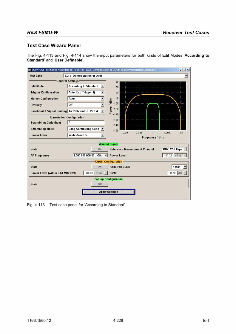
R&S FSMU-W Receiver Test Cases
1166.1560.12 4.229 E-1
Test Case Wizard Panel
The Fig. 4-113 and Fig. 4-114 show the input parameters for both kinds of Edit Modes ‘According to Standard’ and ‘User Definable’.
Fig. 4-113 Test case panel for ‘According to Standard’

Receiver Test Cases R&S FSMU-W
1166.1560.12 4.230 E-1
Fig. 4-114 Test case panel for ‘User Definable’
The input/ouput parameters of the wizard panel read as follows: Wanted Signal State Enables/Disables the signal generation of the wanted 3GPP signal. In
case of ‘According to Standard’ the state is fixed to ‘On’. In case of ‘User Definable’ the user may switch ‘Off’ the state. Remote-control command: :SOUR:BB:W3GP:TS25141:WSIGnal:STATe [ON | OFF]
Reference Measurement Channel
Sets the reference measurement channel. The user can choose from: • RMC 12.2 kbps: 12.2 kbps measurement channel • RMC 64 kbps: 64 kbps measurement channel • RMC 144 kbps: 144 kbps measurement channel (if ‘User Defin-
able’ or static, multipath propagation is selected) • RMC 384 kbps: 384 kbps measurement channel channel (if ‘User
Definable’ or static or multipath propagation is selected) • AMR 12.2 kbps: channel coding for the AMR coder channel (if
‘User Definable’ is selected) Remote-control command: :SOUR:BB:W3GP:TS25141:WSIGnal:DPDCh:CCODing:TYPE M12K2 | M64K | M144k | M384k | AMR
RF Frequency Sets the RF frequency of the wanted signal. Remote-control command: :SOUR:BB:W3GP:TS25141:WSIGnal:FREQ [100.0 KHz .. 6.0 GHz]

R&S FSMU-W Receiver Test Cases
1166.1560.12 4.231 E-1
Power Level (read only) Displays the RF power level of the wanted signal. Remote-control command: :SOUR:BB:W3GP:TS25141:WSIGnal:POW [-145.0 dBm .. 20.0 dBm]
AWGN State Enables/Disables the signal generation of the AWGN. In case of ‘Ac-cording to Standard’ the state is fixed to ‘On’. In case of ‘User De-finable’ the user may switch ‘Off’ the state. Remote-control command: :SOUR:BB:W3GP:TS25141:AWGN:STATe [ON | OFF]
Required BLER (only if ‚According to Standard’)
Sets the required BLER in case of ‘According to Standard’. The items are selectable by the rules: - when Static Propagation (AWGN) • < 0.1 • < 0.01
- when Multipath Fading Case 1 • < 0.1 • < 0.01
- when Multipath Fading Case 2 • < 0.1 • < 0.01
- when Multipath Fading Case 3 • < 0.1 • < 0.01 • < 0.001
- when Multipath Fading Case 4 • < 0.1 • < 0.01 • < 0.001
- when Moving Propagation • < 0.1 • < 0.01
- when Birth/Death Propagation • < 0.1 • < 0.01
Remote-control command: :SOUR:BB:W3GP:TS25141:AWGN:RBLock:RATE B0 | B01 | B001 | B0001
Power Level (within 3.84 MHz BW)
Displays the AWGN power level in case of ‘According to Standard’: • -84 dBm when Wide Area BS • -74 dBm when Medium Range BS • -70 dBm when Local Area BS In case of ‘User Definable’ the user can enter an arbitrary power level. Remote-control command: :SOUR:BB:W3GP:TS25141:AWGN:POW:NOISe
Eb/N0 (read only if ‚According to Standard’)
Sets/Displays the ratio Eb/N0. In case of ‘User Definable’ the user can enter an arbitrary figure. In case of ‘According to Standard’ the figure is read only and determined according to the table Eb/N0 requirements. Remote-control command: :SOUR:BB:W3GP:TS25141:AWGN:ENRatio
Fading State (read only) Displays whether the signals are disturbed by a fading process or not. Remote-control command: :SOUR:BB:W3GP:TS25141:FSIMulator:STATe?

Receiver Test Cases R&S FSMU-W
1166.1560.12 4.232 E-1
Table 4-17 Eb/N0 test requirements in AWGN channel
Measurement channel Received Eb/N0 for BS with Rx diversity
Received Eb/N0 for BS without Rx diversity
Required BLER
12.2 kbps n.a. (5.5 dB) n.a. (8.7 dB) < 10-1 5.5 dB 8.7 dB < 10-2 64 kbps 1.9 dB 5.1 dB < 10-1 2.1 dB 5.2 dB < 10-2 144 kbps 1.2 dB 4.2 dB < 10-1 1.3 dB 4.4 dB < 10-2 384 kbps 1.3 dB 4.4 dB < 10-1 1.4 dB 4.5 dB < 10-2
Fig. 4-115 shows an achieved example signal flow within the SMU after pressing the Apply Settings button.
Fig. 4-115 Routing of baseband A to RF port A and B
Both RF ports A and B hold a reference measurement channel signal that is disturbed by AWGN and multipath fading effects. The test setup pictured in Fig. 4-116 is suitable to measure the base station demodulation performance.
RX A
RX B
Base Stationunder test
BS tester
ChannelSimulator
or ChannelSimulator
AWGN Generator
AWGN Generator
Fig. 4-116 Test Setup according to TS 25.141 for Baseband A Signal Routing to RF Port A
Variation in the Parameters of the Base Station
The measurement must be made at the three frequencies B, M and T. The RMC data rates are 12.2 kbps, 64 kbps, 144 kbps and 384 kbps.

R&S FSMU-W Receiver Test Cases
1166.1560.12 4.233 E-1
Structure of the Measurement
The following diagram illustrates the structure of a measurement: Note: The measurement must be made at frequencies B, M and T. This is represented in the
diagram using f={B,M,T}. The data rate variations are denoted by r={12.2, 64, 144, 384}, the required BLER bounds by b={0.1, 0.01}.
8.2.1
Demodulation ofDCH in StaticPropagationConditions
Init BTS Set BTS to f
Set SMU TestCase Wizard
Trigger SMU
MeasureBLER
next f
f > last freq?n
y
f={B,M,T}
Init SMU
r={12.2, 64,144, 384}
next r
r > last datarate?n
y
Set BTS toRMC r kbps
b={0.1,0.01}
b > last BLER?
yn
next r
Fig. 4-117 Structure of the "Demodulation of DCH in Static Propagation Conditions” measurement

Receiver Test Cases R&S FSMU-W
1166.1560.12 4.234 E-1
Settings on the Base Station
The following table lists the settings to make on the base station: Parameter Value
Frequency B, M and T
RMC 12.2 kbps, 64 kbps, 144 kbps, 384 kbps
Scrambling code Any
Set the frequency to B, M and T and the RMC data rates to 12.2 kbps, 64 kbps, 144 kbps, 384 kbps during the course of the measurements. Steps for Carrying Out a Measurement
1. Set the BTS to the basic state Initialize the BTS, Set the scrambling scheme, Set the frequency, for example, to M.
2. Set the SMU to the basic state Initialize the SMU by pressing the the PRESET key unless some settings (e.g. in terms of I/Q and RF blocks) have to be kept.
3. Set the test case wizard Press Test Case and select Test Case 8.2.1.
The panel adapts to its test case. Press Edit Mode and select According to Standard.
This selection guides the user close to TS 25.141. Press Trigger Configuration and select Auto.
This selection applies to this measurement description. Press Marker Configuration and select Auto.
This selection applies to this measurement description. Select the Diversity reception capabilities of the BTS under test. In case of no Rx diversity press Baseband A Signal Routing and select which RF output port (A or B) is
connected to the BTS. Enter Scrambling Code, Scrambling Mode according to the BTS scrambling scheme. Enter the Power Class of the BTS under test. Press RF Frequency and enter the same frequency (e.g. M) the BTS has set to. Select the Reference Measurement Channel among 12.2 kbps, 64 kbps, 144 kbps and 384 kbps. Select the Required BLER among 1% and 10%. Press Apply Settings.
The SMU is now ready to start signal generation.
4. Start the measurement Send a start trigger impulse (e.g. SFN modulo 4 from the BTS) to the SMU.
The SMU will start signal generation.
5. Calculate the result The BTS internally calculates the BLER.
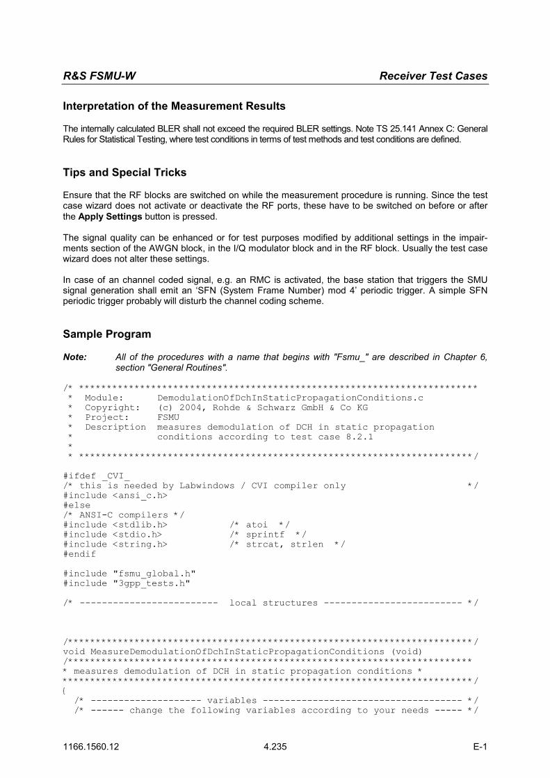
R&S FSMU-W Receiver Test Cases
1166.1560.12 4.235 E-1
Interpretation of the Measurement Results
The internally calculated BLER shall not exceed the required BLER settings. Note TS 25.141 Annex C: General Rules for Statistical Testing, where test conditions in terms of test methods and test conditions are defined. Tips and Special Tricks
Ensure that the RF blocks are switched on while the measurement procedure is running. Since the test case wizard does not activate or deactivate the RF ports, these have to be switched on before or after the Apply Settings button is pressed. The signal quality can be enhanced or for test purposes modified by additional settings in the impair-ments section of the AWGN block, in the I/Q modulator block and in the RF block. Usually the test case wizard does not alter these settings. In case of an channel coded signal, e.g. an RMC is activated, the base station that triggers the SMU signal generation shall emit an ‘SFN (System Frame Number) mod 4’ periodic trigger. A simple SFN periodic trigger probably will disturb the channel coding scheme. Sample Program
Note: All of the procedures with a name that begins with "Fsmu_" are described in Chapter 6, section "General Routines".
/* ************************************************************************ * Module: DemodulationOfDchInStaticPropagationConditions.c * Copyright: (c) 2004, Rohde & Schwarz GmbH & Co KG * Project: FSMU * Description measures demodulation of DCH in static propagation * conditions according to test case 8.2.1 * * ***********************************************************************/ #ifdef _CVI_ /* this is needed by Labwindows / CVI compiler only */ #include <ansi_c.h> #else /* ANSI-C compilers */ #include <stdlib.h> /* atoi */ #include <stdio.h> /* sprintf */ #include <string.h> /* strcat, strlen */ #endif #include "fsmu_global.h" #include "3gpp_tests.h" /* ------------------------- local structures ------------------------- */ /*************************************************************************/ void MeasureDemodulationOfDchInStaticPropagationConditions (void) /************************************************************************* * measures demodulation of DCH in static propagation conditions * **************************************************************************/ { /* -------------------- variables ------------------------------------ */ /* ------ change the following variables according to your needs ----- */
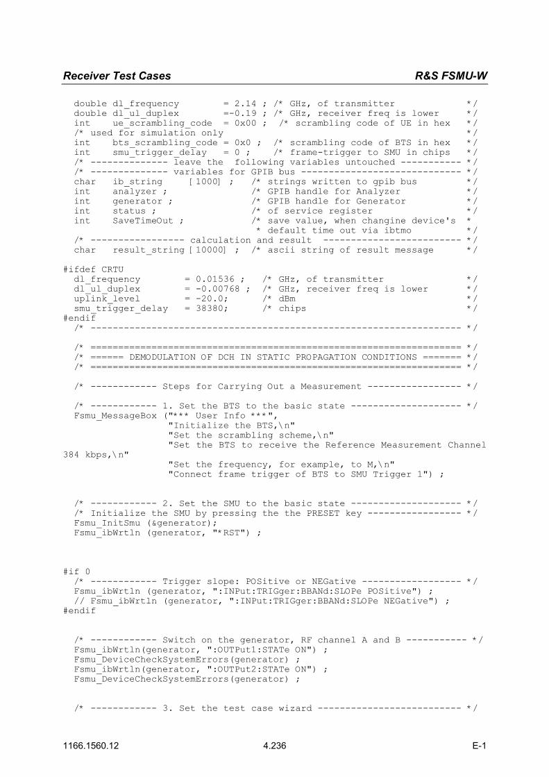
Receiver Test Cases R&S FSMU-W
1166.1560.12 4.236 E-1
double dl_frequency = 2.14 ; /* GHz, of transmitter */ double dl_ul_duplex =-0.19 ; /* GHz, receiver freq is lower */ int ue_scrambling_code = 0x00 ; /* scrambling code of UE in hex */ /* used for simulation only */ int bts_scrambling_code = 0x0 ; /* scrambling code of BTS in hex */ int smu_trigger_delay = 0 ; /* frame-trigger to SMU in chips */ /* -------------- leave the following variables untouched ----------- */ /* -------------- variables for GPIB bus ----------------------------- */ char ib_string [1000] ; /* strings written to gpib bus */ int analyzer ; /* GPIB handle for Analyzer */ int generator ; /* GPIB handle for Generator */ int status ; /* of service register */ int SaveTimeOut ; /* save value, when changine device's * * default time out via ibtmo */ /* ----------------- calculation and result ------------------------- */ char result_string [10000] ; /* ascii string of result message */ #ifdef CRTU dl_frequency = 0.01536 ; /* GHz, of transmitter */ dl_ul_duplex = -0.00768 ; /* GHz, receiver freq is lower */ uplink_level = -20.0; /* dBm */ smu_trigger_delay = 38380; /* chips */ #endif /* ------------------------------------------------------------------- */ /* =================================================================== */ /* ====== DEMODULATION OF DCH IN STATIC PROPAGATION CONDITIONS ======= */ /* =================================================================== */ /* ------------ Steps for Carrying Out a Measurement ----------------- */ /* ------------ 1. Set the BTS to the basic state -------------------- */ Fsmu_MessageBox ("*** User Info ***", "Initialize the BTS,\n" "Set the scrambling scheme,\n" "Set the BTS to receive the Reference Measurement Channel 384 kbps,\n" "Set the frequency, for example, to M,\n" "Connect frame trigger of BTS to SMU Trigger 1") ; /* ------------ 2. Set the SMU to the basic state -------------------- */ /* Initialize the SMU by pressing the the PRESET key ----------------- */ Fsmu_InitSmu (&generator); Fsmu_ibWrtln (generator, "*RST") ; #if 0 /* ------------ Trigger slope: POSitive or NEGative ------------------ */ Fsmu_ibWrtln (generator, ":INPut:TRIGger:BBANd:SLOPe POSitive") ; // Fsmu_ibWrtln (generator, ":INPut:TRIGger:BBANd:SLOPe NEGative") ; #endif /* ------------ Switch on the generator, RF channel A and B ----------- */ Fsmu_ibWrtln(generator, ":OUTPut1:STATe ON") ; Fsmu_DeviceCheckSystemErrors(generator) ; Fsmu_ibWrtln(generator, ":OUTPut2:STATe ON") ; Fsmu_DeviceCheckSystemErrors(generator) ; /* ------------ 3. Set the test case wizard -------------------------- */

R&S FSMU-W Receiver Test Cases
1166.1560.12 4.237 E-1
/* ------------ Enter Test Case: Test Case 8.2.1 ---------------------- */ Fsmu_ibWrtln (generator, ":SOUR:BB:W3GP:TS25141:TCASe TC821") ; /* ------------ Set Edit Mode to According to Standard. -------------- */ Fsmu_ibWrtln (generator, ":SOUR:BB:W3GP:TS25141:EMODe STANdard") ; /* ------------ Set Trigger Configuration and select Auto. ----------- */ Fsmu_ibWrtln (generator, ":SOUR:BB:W3GP:TS25141:TRIGger AUTO") ; /* ------------ Set Marker Configuration and select Auto. ------------ */ Fsmu_ibWrtln (generator, ":SOUR:BB:W3GP:TS25141:TRIGger:OUTPut AUTO") ; /* ------------ Set Rx diversity to On ------------------------------- */ Fsmu_ibWrtln (generator, ":SOUR:BB:W3GP:TS25141:RXDiversity ON") ; /* ------------ Enter Scrambling Code, Scrambling Mode --------------- */ /* %1x prints an integer in hex at least one digit ------------------- */ sprintf (ib_string, ":SOUR:BB:W3GP:TS25141:SCODe %1x", ue_scrambling_code) ; Fsmu_ibWrtln(generator, ib_string) ; Fsmu_ibWrtln(generator, ":SOUR:BB:W3GP:TS25141:SCODe:MODE LONG") ; /* ------------ Enter the Power Class of the BTS under test. --------- */ Fsmu_ibWrtln (generator, ":SOUR:BB:W3GP:TS25141:BSPClass WIDE") ; /* ------------ Enter RF Frequency ----------------------------------- */ /* Set SMU to the UL frequency of the base station ------------------- */ sprintf (ib_string, ":SOUR:BB:W3GP:TS25141:WSIGnal:FREQ %g GHz", dl_frequency + dl_ul_duplex) ; Fsmu_ibWrtln (generator, ib_string) ; /* ------------ Set the Reference Measurement Channel, e.g. 384 kbps - */ Fsmu_ibWrtln (generator, ":SOUR:BB:W3GP:TS25141:WSIGnal:DPDCh:CCODing:TYPE M384k") ; /* ------------ Set the Required BLER, e.g to 0.01. ------------------ */ Fsmu_ibWrtln (generator, ":SOUR:BB:W3GP:TS25141:AWGN:RBLock:RATE B001"); /* ------------ Press Apply Settings. -------------------------------- */ /* This may take a long time, so set time out temporarily to 100 sec - */ Fsmu_ibGetTmo(generator, &SaveTimeOut) ; Fsmu_ibTmo (generator, T100s) ; Fsmu_ibWrtln (generator, ":SOUR:BB:W3GP:TS25141:TCASe:EXECute") ; Fsmu_WaitForDevice(generator); // Fsmu_ibWrtln(generator, "*OPC?"); Fsmu_ibRd (generator, ib_string, sizeof (ib_string)) ; Fsmu_ibTmo (generator, SaveTimeOut) ; /* ------- Examples of SMU settings after the test case wizards ------ */ #if 0 /* ------- input trigger delay: only positive values are allowed ----- */ sprintf (ib_string, ":BB:W3GP:TRIGger:EXTernal:DELay %d", smu_trigger_delay) ; Fsmu_ibWrtln (generator, ib_string) ; /* -------------- adjust output power to 0 dB ------------------------ */ Fsmu_ibWrtln(generator, ":BB:W3GPp:POWer:ADJust") ; /* ------------------ Stop SMU to get defined timing ----------------- */ Fsmu_ibWrtln (generator, ":BB:W3GPp:TRIGger:ARM:EXECute;*OPC?") ; Fsmu_ibRd (generator, ib_string, sizeof (ib_string)) ; /* -------- adjust output power to 0 dB and wait for execution ------- */ Fsmu_ibWrtln(generator, ":BB:W3GPp:POWer:ADJust;*OPC?") ; Fsmu_ibRd (generator, ib_string, sizeof (ib_string)) ;

Receiver Test Cases R&S FSMU-W
1166.1560.12 4.238 E-1
/* ------------- enable external trigger in SMU ---------------------- */ if (!Fsmu_GetBtsEmulation()) { Fsmu_ibWrtln (generator, ":BB:W3GP:TRIGger:SOURce EXTernal;*OPC?") ; Fsmu_ibRd (generator, ib_string, sizeof (ib_string)) ; } else { Fsmu_ibWrtln (generator, ":BB:W3GP:TRIGger:EXECute;*OPC?") ; Fsmu_ibRd (generator, ib_string, sizeof (ib_string)) ; } #endif /* ------------------------------------------------------------------- */ /* ------------ The SMU is now ready to start signal generation ------ */ /* ------------------------------------------------------------------- */ /* ------------ 4. Start the measurement ----------------------------- */ /* Send a start trigger impulse to the SMU. -------------------------- */ /* The SMU will start signal generation. ------------------------------*/ /* ------------ 5. Calculate the result ------------------------------ */ /* The BTS internally calculates the BLER. ---------------------------- */ #ifdef FSMU_LOG_DATA /* ------------------------------------------------------------------- */ /* ------------ Write output data file; --------------- */ /* ------------------------------------------------------------------- */ { FILE * myfile ; myfile = fopen ("demodulation_of_DCH_in_static_propagation_conditions.dat", "w") ; if (myfile) { fprintf (myfile, " This is a data file"); fclose (myfile) ; } } #endif /* ----------- Display the result ------------------------------------*/ sprintf (result_string , "----------------------------------------\n" " demodulation of DCH in static propagation conditions\n" "------------ -------------\n"); Fsmu_MessageBox ("*** Result ***", result_string) ; /* --------------------- Close SMU on GPIB --------------------------- */ Fsmu_CloseSmu (generator) ; }

R&S FSMU-W Receiver Test Cases
1166.1560.12 4.239 E-1
Test Case 8.3.1: Demodulation of DCH in Multipath Fading Case 1 Conditions
This test case is identical to test case 8.2.1 except from the channel simulation that is set to ‘Multipath Fading Case 1’ and Eb/N0 test requirements. Eb/N0 test requirements
Measurement channel Received Eb/N0 for BS with Rx diversity
Received Eb/N0 for BS without Rx diversity
Required BLER
12.2 kbps n.a. (12.5 dB) n.a. (19.7 dB) < 10-1
12.5 dB 19.7 dB < 10-2
64 kbps 6.8 dB 12.2 dB < 10-1
9.8 dB 16.5 dB < 10-2
144 kbps 6.0 dB 11.4 dB < 10-1
9.0 dB 15.6 dB < 10-2
384 kbps 6.4 dB 11.8 dB < 10-1
9.4 dB 16.1 dB < 10-2
Recommended Options
Besides the basic configuration (R&S FSMU3-W, R&S FSMU8-W or R&S FSMU26-W) the options
• R&S FSMU-B1 (consisting of R&S SMU-B203 2nd RF path (3.0 GHz), R&S SMU-B13 Baseband main module, R&S SMU-K62 Additive white Gaussian noise, R&S SMU-B36 High output power) and
• R&S FSMU-B3 (consisting of R&S SMU-B14 Fading simulator, R&S SMU-B152x Fading simulator extension, R&S SMU-K71 Dynamic Fading)
are required to set up the R&S SMU.

Receiver Test Cases R&S FSMU-W
1166.1560.12 4.240 E-1
Test Case 8.3.2: Demodulation of DCH in Multipath Fading Case 2 Conditions
This test case is identical to test case 8.2.1 except from the channel simulation that is set to ‘Multipath Fading Case 2’ and Eb/N0 test requirements. Eb/N0 Test requirements in Multipath Case 2 channel
Measurement channel Received Eb/N0 for BS with Rx diversity
Received Eb/N0 for BS without Rx diversity
Required BLER
12.2 kbps n.a. (9.6 dB) n.a. (15.6 dB) < 10-1
9.6 dB 15.6 dB < 10-2
64 kbps 4.9 dB 9.8 dB < 10-1
7.0 dB 12.9 dB < 10-2
144 kbps 4.3 dB 8.8 dB < 10-1
6.2 dB 12.1 dB < 10-2
384 kbps 4.7 dB 9.3 dB < 10-1
6.7 dB 12.7dB < 10-2
Recommended Options
Besides the basic configuration (FSMU3-W, FSMU8-W or FSMU26-W) the options
• FSMU-B1 (consisting of R&S SMU-B203 2nd RF path (3.0 GHz), R&S SMU-B13 Baseband main module, R&S SMU-K62 Additive white Gaussian noise, R&S SMU-B36 High output power) and
• FSMU-B3 (consisting of R&S SMU-B14 Fading simulator, R&S SMU-B152x Fading simulator exten-sion, R&S SMU-K71 Dynamic Fading)
are required to set up the R&S SMU.

R&S FSMU-W Receiver Test Cases
1166.1560.12 4.241 E-1
Test Case 8.3.3: Demodulation of DCH in Multipath Fading Case 3 Conditions
This test case is identical to test case 8.3.1 except from the channel simulation that is set to ‘Multipath Fading Case 3’ (Fading menu: Standard = 3GPP Case 3 UE/BS) and the Eb/N0 test requirements (see following table).
Table 4-18 Eb/N0 Test requirements in multipath Case 3 channel
Measurement channel Received Eb/N0 for BS with Rx diversity
Received Eb/N0 for BS without Rx diversity
Required BLER
12.2 kbps n.a. (7.8 dB) n.a. (11.4 dB) < 10-1
7.8 dB 11.4 dB < 10-2
8.6 dB 12.3 dB < 10-3
64 kbps 4.0 dB 7.7 dB < 10-1
4.4 dB 8.3 dB < 10-2
4.7 dB 9.1 dB < 10-3
144 kbps 3.4 dB 6.6 dB < 10-1
3.8 dB 7.3 dB < 10-2
4.2 dB 7.8 dB < 10-3
384 kbps 3.8 dB 7.1 dB < 10-1
4.2 dB 7.8 dB < 10-2
4.8 dB 8.5 dB < 10-3
Recommended Options
Besides the basic configuration (R&S FSMU3-W, R&S FSMU8-W or R&S FSMU26-W) the options
• R&S FSMU-B1 (consisting of R&S SMU-B203 2nd RF path (3.0 GHz), R&S SMU-B13 Baseband main module, R&S SMU-K62 Additive white Gaussian noise, R&S SMU-B36 High output power) and
• R&S FSMU-B3 (consisting of R&S SMU-B14 Fading simulator, R&S SMU-B152x Fading simulator extension, R&S SMU-K71 Dynamic Fading)
are required to set up the R&S SMU.

Receiver Test Cases R&S FSMU-W
1166.1560.12 4.242 E-1
Test Case 8.3.4: Demodulation of DCH in Multipath Fading Case 4 Conditions
This test case is identical to test case 8.2.1 except from the channel simulation that is set to ‘Multipath Fading Case 4’ and Eb/N0 test requirements. Eb/N0 Test requirements in multipath Case 4 channel
Measurement channel Received Eb/N0 for BS with Rx diversity
Received Eb/N0 for BS without Rx diversity
Required BLER
12.2 kbps n.a. (10.8 dB) n.a. (14.4 dB) < 10-1
10.8 dB 14.4 dB < 10-2
11.6 dB 15.3 dB < 10-3
64 kbps 7.0 dB 10.7 dB < 10-1
7.4 dB 11.3 dB < 10-2
7.7 dB 12.1 dB < 10-3
144 kbps 6.4 dB 9.6 dB < 10-1
6.8 dB 10.3 dB < 10-2
7.2 dB 10.8 dB < 10-3
384 kbps 6.8 dB 10.1 dB < 10-1
7.2 dB 10.8 dB < 10-2
7.8 dB 11.5 dB < 10-3
Recommended Options
Besides the basic configuration (R&S FSMU3-W, R&S FSMU8-W or R&S FSMU26-W) the options
• R&S FSMU-B1 (consisting of R&S SMU-B203 2nd RF path (3.0 GHz), R&S SMU-B13 Baseband main module, R&S SMU-K62 Additive white Gaussian noise, R&S SMU-B36 High output power) and
• R&S FSMU-B3 (consisting of R&S SMU-B14 Fading simulator, R&S SMU-B152x Fading simulator extension, R&S SMU-K71 Dynamic Fading)
are required to set up the SMU.

R&S FSMU-W Receiver Test Cases
1166.1560.12 4.243 E-1
Test Case 8.4: Demodulation of DCH in Moving Propagation Condi-tions
This test case is identical to test case 8.2.1 except from the channel simulation that is set to ‘Moving Propagation’ and Eb/N0 test requirements. Eb/N0 Test requirements in multipath Case 4 channel
Measurement channel Received Eb/N0 for BS with Rx diversity
Received Eb/N0 for BS without Rx diversity
Required BLER
12.2 kbps n.a. (10.8 dB) n.a. (14.4 dB) < 10-1
10.8 dB 14.4 dB < 10-2
11.6 dB 15.3 dB < 10-3
64 kbps 7.0 dB 10.7 dB < 10-1
7.4 dB 11.3 dB < 10-2
7.7 dB 12.1 dB < 10-3
144 kbps 6.4 dB 9.6 dB < 10-1
6.8 dB 10.3 dB < 10-2
7.2 dB 10.8 dB < 10-3
384 kbps 6.8 dB 10.1 dB < 10-1
7.2 dB 10.8 dB < 10-2
7.8 dB 11.5 dB < 10-3
Recommended Options
Besides the basic configuration (R&S FSMU3-W, R&S FSMU8-W or R&S FSMU26-W) the options
• R&S FSMU-B1 (consisting of R&S SMU-B203 2nd RF path (3.0 GHz), R&S SMU-B13 Baseband main module, R&S SMU-K62 Additive white Gaussian noise, R&S SMU-B36 High output power) and
• R&S FSMU-B3 (consisting of R&S SMU-B14 Fading simulator, R&S SMU-B152x Fading simulator extension, R&S SMU-K71 Dynamic Fading)
are required to set up the R&S SMU.

Receiver Test Cases R&S FSMU-W
1166.1560.12 4.244 E-1
Test Case 8.5: Demodulation of DCH in Birth/Death Propagation Conditions
This test case is identical to test case 8.2.1 except from the channel simulation that is set to ‘Birth/Death Propagation’ and Eb/N0 test requirements. Eb/N0 Test requirements in birth/death channel
Measurement channel Received Eb/N0 for BS with Rx diversity
Received Eb/N0 for BS without Rx diversity
Required BLER
12.2 kbps n.a. (8.3 dB) n.a. (11.4 dB) < 10-1
8.3 dB 11.4 dB < 10-2
64 kbps 4.7 dB 8.0 dB < 10-1
4.8 dB 8.1 dB < 10-2
Recommended Options
Besides the basic configuration (R&S FSMU3-W, R&S FSMU8-W or R&S FSMU26-W) the options
• R&S FSMU-B1 (consisting of R&S SMU-B203 2nd RF path (3.0 GHz), R&S SMU-B13 Baseband main module, R&S SMU-K62 Additive white Gaussian noise, R&S SMU-B36 High output power) and
• R&S FSMU-B3 (consisting of R&S SMU-B14 Fading simulator, R&S SMU-B152x Fading simulator extension, R&S SMU-K71 Dynamic Fading)
are required to set up the R&S SMU.

R&S FSMU-W Receiver Test Cases
1166.1560.12 4.245 E-1
Test Case 8.6: Verification of Internal BLER
Test Purpose
The test case shall verify that a BS receiver has the capability to calculate the BER of a signal where erroneous blocks are inserted in the data stream by the SMU. The test is passed when the calculated BLER is close to the simulated BLER at the test frequencies B, M and T. Quotation from [1]:
Base Station System with internal BLER calculates block error rate from the CRC blocks of the received. This test is performed only if Base Station System has this kind of feature. All data rates which are used in clause 8 Performance requirement testing shall be used in verification testing. This test is performed by feeding measurement signal with known BLER to the input of the re-ceiver. Locations of the erroneous blocks shall be randomly distributed within a frame. Erroneous blocks shall be inserted into the UL signal as shown in figure 8.1.
Test Setup
The test setup pictured in Fig. 4-118 is suitable to verify the base station internal BER and BLER calculation. with diversity:
without diversity:
Fig. 4-118 Test Setup according to TS 25.141 for Baseband A Signal Routing to RF Port A
In case of diversity measurements both RF ports A and B hold the the wanted signal and both RF ports A and be shall be connected to the base station receiver ports. In case of no diversity measurements a single RF port A or B (depends on the Smus routing scheme) is connected to the single base station receiver port. The SMU will start signal generation by the first BS frame trigger sent to trigger port Trigger 1.

Receiver Test Cases R&S FSMU-W
1166.1560.12 4.246 E-1
Recommended Options
Besides the basic configuration (R&S FSMU3-W, R&S FSMU8-W or R&S FSMU26-W) the option R&S FSMU-B1 (consisting of R&S SMU-B203 2nd RF path (3.0 GHz), R&S SMU-B13 Baseband main mod-ule, R&S SMU-K62 Additive white Gaussian noise, R&S SMU-B36 High output power) and is required to set up the R&S SMU. Test Case Wizard Panel
The Fig. 4-119 and Fig. 4-120 show the input parameters for both kinds of Edit Modes ‘According to Standard’ and ‘User Definable’.
Fig. 4-119 Test case panel for ‘According to Standard’

R&S FSMU-W Receiver Test Cases
1166.1560.12 4.247 E-1
Fig. 4-120 Test case panel for ‘User Definable’
The input/ouput parameters of the wizard panel read as follows: Wanted Signal State Enables/Disables the signal generation of the wanted 3GPP signal. In
case of ‘According to Standard’ the state is fixed to ‘On’. In case of ‘User Definable’ the user may switch ‘Off’ the state. Remote-control command: :SOUR:BB:W3GP:TS25141:WSIGnal:STATe [ON | OFF]
Reference Measurement Channel
Sets the reference measurement channel. The user can choose from: • RMC 12.2 kbps: 12.2 kbps measurement channel • RMC 64 kbps: 64 kbps measurement channel • RMC 144 kbps: 144 kbps measurement channel • RMC 384 kbps: 384 kbps measurement channel • AMR 12.2 kbps: channel coding for the AMR coder In case of ‘User Definable’ the choice is extended to AMR 12.2 kbps. Remote-control command: :SOUR:BB:W3GP:TS25141:WSIGnal:DPDCh:CCODing:TYPE M12K2 | M64K | M144k | M384k | AMR
RF Frequency Sets the RF frequency of the wanted signal. Remote-control command: :SOUR:BB:W3GP:TS25141:WSIGnal:FREQ [100.0 KHz .. 6.0 GHz]
Power Level Displays the RF power level of the wanted signal in case of ‘Accord-ing to Standard’. It dependes on data rate and BS power class accord-ing to Table 4-19. In case of ‘User Definable’ the user can enter an arbitray power level figure.

Receiver Test Cases R&S FSMU-W
1166.1560.12 4.248 E-1
Remote-control command: :SOUR:BB:W3GP:TS25141:WSIGnal:POW [-145.0 dBm .. 20.0 dBm]
Bit Error Ratio (BER) (in case of ‚User Definable’)
Sets the Bit Error Ratio. The user can enter an arbitray BER figure below or equal to 0.1. Remote-control command: :SOUR:BB:W3GP:TS25141:WSIGnal:DPDCh:DERR:BIT:RATE [0.0 .. 0.1]
Block Error Rate (BLER) Sets the Block Error Ratio. In case of ‘According to Standard’ the user can choose from • 0.00: No block errors are inserted • 0.01: The BLER is 1% In case of ‘User Definable’ the user can enter an arbitray BLER figure below or equal to 0.1. Remote-control command: :SOUR:BB:W3GP:TS25141:WSIGnal:DPDCh:DERR:BLOCk:RATE [0.0 .. 0.1]
Table 4-19 UL Signal levels for different data rates
Data rate Signal level for Wide Area BS
Signal level for Me-dium Range BS
Signal level for Local Area BS
Unit
12,2 kbps -111 -101 -97 dBm/3.84 MHz
64 kbps -107 -97 -93 dBm/3.84 MHz
144 kbps -104 -94 -90 dBm/3.84 MHz
384 kbps -100 -90 -86 dBm/3.84 MHz
Fig. 4-121 show an achieved example signal flow within the SMU after pressing the Apply Settings button.
Fig. 4-121 Routing of baseband A to RF port A and B in case of BLER test

R&S FSMU-W Receiver Test Cases
1166.1560.12 4.249 E-1
In case of routing to path A/B the RF port A/B holds a corrupted reference measurement channel signal. In case of BLER tests both RF ports are active and can be connected to the base station for diversity reception. The test setup pictured in Fig. 4-122 is suitable to verify the base station internal BER and BLER calculation.
a) Functional Set-up for Verification of the internal BLER calculation for BS with Rx diversity
b) Functional Set-up for Verification of the internal BER calculation
Fig. 4-122 Test Setup according to TS 25.141 for Baseband A Signal Routing to RF Port A
Variation in the Parameters of the Base Station
The measurement must be made at the three frequencies B, M and T. The RMC data rates are 12.2 kbps, 64 kbps, 144 kbps and 384 kbps.

Receiver Test Cases R&S FSMU-W
1166.1560.12 4.250 E-1
Structure of the Measurement
The following diagram illustrates the structure of a measurement: Note: The measurement must be made at frequencies B, M and T. This is represented in the diagram
using f={B,M,T}. The data rate variations are denoted by r={12.2, 64, 144, 384}.
8.6 Verification ofthe Internal BLER
Calculation
Init BTS Set BTS to f
Set SMU TestCase Wizard
Trigger SMU
MeasureBLER
next f
f > last freq?n
y
f={B,M,T}
Init SMU
r={12.2, 64,144, 384}
next r
r > last datarate?n
y
Set BTS toRMC r kbps
Fig. 4-123 Structure of the "Verification of the Internal BLER Calculation” measurement

R&S FSMU-W Receiver Test Cases
1166.1560.12 4.251 E-1
Settings on the Base Station
The following table lists the settings to make on the base station: Parameter Value
Frequency B, M and T
RMC 12.2 kbps, 64 kbps, 144 kbps, 384 kbps
Scrambling code Any
Set the frequency to B, M and T and the RMC data rates to 12.2 kbps, 64 kbps, 144 kbps, 384 kbps during the course of the measurements. Steps for Carrying Out a Measurement
1. Set the BTS to the basic state Initialize the BTS, Set the scrambling scheme, Set the frequency, for example, to M.
2. Set the SMU to the basic state Initialize the SMU by pressing the the PRESET key unless some settings (e.g. in terms of I/Q and RF blocks) have to be kept.
3. Set the test case wizard
Press Test Case and select Test Case 8.6. The panel adapts to its test case.
Press Edit Mode and select According to Standard. This selection guides the user close to TS 25.141.
Press Trigger Configuration and select Auto. This selection applies to this measurement description.
Press Marker Configuration and select Auto. This selection applies to this measurement description.
Select the Diversity reception capabilities of the BTS under test. In case of no Rx diversity press Baseband A Signal Routing and select which RF output port (A or B) is
connected to the BTS. Enter Scrambling Code, Scrambling Mode according to the BTS scrambling scheme. Enter the Power Class of the BTS under test. Press RF Frequency and enter the same frequency (e.g. M) the BTS has set to. Select the Reference Measurement Channel among 12.2 kbps, 64 kbps, 144 kbps and 384 kbps. Press Block Error Rate and enter 0.01. Press Apply Settings.
The SMU is now ready to start signal generation.
4. Start the measurement Send a start trigger impulse (e.g. SFN modulo 4 from the BTS) to the SMU.
The SMU will start signal generation.
5. Calculate the result The BTS internally calculates the BLER.

Receiver Test Cases R&S FSMU-W
1166.1560.12 4.252 E-1
Interpretation of the Measurement Results
The internally calculated BLER shall be within ±10% of the BLER generated by the SMU. Note TS 25.141 Annex C: General Rules for Statistical Testing, where test conditions in terms of test methods and test conditions are defined. Tips and Special Tricks
Ensure that the RF blocks are switched on while the measurement procedure is running. Since the test case wizard does not activate or deactivate the RF ports, these have to be switched on before or after the Apply Settings button is pressed. The signal quality can be enhanced or for test purposes modified by additional settings in the impair-ments section of the AWGN block, in the I/Q modulator block and in the RF block. Usually the test case wizard does not alter these settings. In case of an channel coded signal, e.g. an RMC is activated, the base station that triggers the SMU signal generation shall emit an ‘SFN (System Frame Number) mod 4’ periodic trigger. A simple SFN periodic trigger probably will disturb the channel coding scheme. Sample Program
Note: All of the procedures with a name that begins with "Fsmu_" are described in Chapter 6, section "General Routines".
/* ************************************************************************ * Module: VerificationOfTheInternalBlerCalculation.c * Copyright: (c) 2004, Rohde & Schwarz GmbH & Co KG * Project: FSMU * Description measures the verification of the internal BER calculation * according to test case 8.6 * * ***********************************************************************/ #ifdef _CVI_ /* this is needed by Labwindows / CVI compiler only */ #include <ansi_c.h> #else /* ANSI-C compilers */ #include <stdlib.h> /* atoi */ #include <stdio.h> /* sprintf */ #include <string.h> /* strcat, strlen */ #endif #include "fsmu_global.h" #include "3gpp_tests.h" /* ------------------------- local structures ------------------------- */ /*************************************************************************/ void MeasureVerificationOfTheInternalBlerCalculation (void) /************************************************************************* * measures the verification of the internal BLER calculation * **************************************************************************/ { /* -------------------- variables ------------------------------------ */

R&S FSMU-W Receiver Test Cases
1166.1560.12 4.253 E-1
/* ------ change the following variables according to your needs ----- */ double dl_frequency = 2.14 ; /* GHz, of transmitter */ double dl_ul_duplex =-0.19 ; /* GHz, receiver freq is lower */ int ue_scrambling_code = 0x00 ; /* scrambling code of UE in hex */ /* used for simulation only */ int bts_scrambling_code = 0x0 ; /* scrambling code of BTS in hex */ int smu_trigger_delay = 0 ; /* frame-trigger to SMU in chips */ /* -------------- leave the following variables untouched ----------- */ /* -------------- variables for GPIB bus ----------------------------- */ char ib_string [1000] ; /* strings written to gpib bus */ int analyzer ; /* GPIB handle for Analyzer */ int generator ; /* GPIB handle for Generator */ int status ; /* of service register */ int SaveTimeOut ; /* save value, when changine device's * * default time out via ibtmo */ /* ----------------- calculation and result ------------------------- */ char result_string [10000] ; /* ascii string of result message */ #ifdef CRTU dl_frequency = 0.01536 ; /* GHz, of transmitter */ dl_ul_duplex = -0.00768 ; /* GHz, receiver freq is lower */ uplink_level = -20.0; /* dBm */ smu_trigger_delay = 38380; /* chips */ #endif /* ------------------------------------------------------------------- */ /* =================================================================== */ /* ======== VERIFICATION OF THE INTERNAL BLER CALCULATION ============ */ /* =================================================================== */ /* ------------ Steps for Carrying Out a Measurement ----------------- */ /* ------------ 1. Set the BTS to the basic state -------------------- */ Fsmu_MessageBox ("*** User Info ***", "Initialize the BTS,\n" "Set the scrambling scheme,\n" "Set the BTS to receive the Reference Measurement Channel 144 kbps,\n" "Set the frequency, for example, to M,\n" "Connect frame trigger of BTS to SMU Trigger 1") ; /* ------------ 2. Set the SMU to the basic state -------------------- */ /* Initialize the SMU by pressing the the PRESET key ----------------- */ Fsmu_InitSmu (&generator); Fsmu_ibWrtln (generator, "*RST") ; #if 0 /* ------------ Trigger slope: POSitive or NEGative ------------------ */ Fsmu_ibWrtln (generator, ":INPut:TRIGger:BBANd:SLOPe POSitive") ; // Fsmu_ibWrtln (generator, ":INPut:TRIGger:BBANd:SLOPe NEGative") ; #endif /* ------------ Switch on the generator, RF channel A and B ----------- */ Fsmu_ibWrtln(generator, ":OUTPut1:STATe ON") ; Fsmu_DeviceCheckSystemErrors(generator) ; Fsmu_ibWrtln(generator, ":OUTPut2:STATe ON") ; Fsmu_DeviceCheckSystemErrors(generator) ;

Receiver Test Cases R&S FSMU-W
1166.1560.12 4.254 E-1
/* ------------ 3. Set the test case wizard -------------------------- */ /* ------------ Enter Test Case: Test Case 8.6 ----------------------- */ Fsmu_ibWrtln (generator, ":SOUR:BB:W3GP:TS25141:TCASe TC86") ; /* ------------ Set Edit Mode to According to Standard. -------------- */ Fsmu_ibWrtln (generator, ":SOUR:BB:W3GP:TS25141:EMODe STANdard") ; /* ------------ Set Trigger Configuration and select Auto. ----------- */ Fsmu_ibWrtln (generator, ":SOUR:BB:W3GP:TS25141:TRIGger AUTO") ; /* ------------ Set Marker Configuration and select Auto. ------------ */ Fsmu_ibWrtln (generator, ":SOUR:BB:W3GP:TS25141:TRIGger:OUTPut AUTO") ; /* ------------ Set Rx diversity to On ------------------------------- */ Fsmu_ibWrtln (generator, ":SOUR:BB:W3GP:TS25141:RXDiversity ON") ; /* ------------ Enter Scrambling Code, Scrambling Mode --------------- */ /* %1x prints an integer in hex at least one digit ------------------- */ sprintf (ib_string, ":SOUR:BB:W3GP:TS25141:SCODe %1x", ue_scrambling_code) ; Fsmu_ibWrtln(generator, ib_string) ; Fsmu_ibWrtln(generator, ":SOUR:BB:W3GP:TS25141:SCODe:MODE LONG") ; /* ------------ Enter the Power Class of the BTS under test. --------- */ Fsmu_ibWrtln (generator, ":SOUR:BB:W3GP:TS25141:BSPClass WIDE") ; /* ------------ Enter RF Frequency ----------------------------------- */ /* Set SMU to the UL frequency of the base station ------------------- */ sprintf (ib_string, ":SOUR:BB:W3GP:TS25141:WSIGnal:FREQ %g GHz", dl_frequency + dl_ul_duplex) ; Fsmu_ibWrtln (generator, ib_string) ; /* ------------ Set the Reference Measurement Channel, e.g. 144 kbps - */ Fsmu_ibWrtln (generator, ":SOUR:BB:W3GP:TS25141:WSIGnal:DPDCh:CCODing:TYPE M144k") ; /* ------------ Set the BLER to 0.01. -------------------------------- */ Fsmu_ibWrtln (generator, ":SOUR:BB:W3GP:TS25141:WSIGnal:DPDCh:DERR:BLOCk:RATE 0.01"); /* ------------ Press Apply Settings. -------------------------------- */ /* This may take a long time, so set time out temporarily to 100 sec - */ Fsmu_ibGetTmo(generator, &SaveTimeOut) ; Fsmu_ibTmo (generator, T100s) ; Fsmu_ibWrtln (generator, ":SOUR:BB:W3GP:TS25141:TCASe:EXECute") ; Fsmu_WaitForDevice(generator); // Fsmu_ibWrtln(generator, "*OPC?"); Fsmu_ibRd (generator, ib_string, sizeof (ib_string)) ; Fsmu_ibTmo (generator, SaveTimeOut) ; /* ------- Examples of SMU settings after the test case wizards ------ */ #if 0 /* ------- input trigger delay: only positive values are allowed ----- */ sprintf (ib_string, ":BB:W3GP:TRIGger:EXTernal:DELay %d", smu_trigger_delay) ; Fsmu_ibWrtln (generator, ib_string) ; /* -------------- adjust output power to 0 dB ------------------------ */ Fsmu_ibWrtln(generator, ":BB:W3GPp:POWer:ADJust") ; /* ------------------ Stop SMU to get defined timing ----------------- */ Fsmu_ibWrtln (generator, ":BB:W3GPp:TRIGger:ARM:EXECute;*OPC?") ; Fsmu_ibRd (generator, ib_string, sizeof (ib_string)) ; /* -------- adjust output power to 0 dB and wait for execution ------- */

R&S FSMU-W Receiver Test Cases
1166.1560.12 4.255 E-1
Fsmu_ibWrtln(generator, ":BB:W3GPp:POWer:ADJust;*OPC?") ; Fsmu_ibRd (generator, ib_string, sizeof (ib_string)) ; /* ------------- enable external trigger in SMU ---------------------- */ if (!Fsmu_GetBtsEmulation()) { Fsmu_ibWrtln (generator, ":BB:W3GP:TRIGger:SOURce EXTernal;*OPC?") ; Fsmu_ibRd (generator, ib_string, sizeof (ib_string)) ; } else { Fsmu_ibWrtln (generator, ":BB:W3GP:TRIGger:EXECute;*OPC?") ; Fsmu_ibRd (generator, ib_string, sizeof (ib_string)) ; } #endif /* ------------------------------------------------------------------- */ /* ------------ The SMU is now ready to start signal generation ------ */ /* ------------------------------------------------------------------- */ /* ------------ 4. Start the measurement ----------------------------- */ /* Send a start trigger impulse to the SMU. -------------------------- */ /* The SMU will start signal generation. ------------------------------*/ /* ------------ 5. Calculate the result ------------------------------ */ /* The BTS internally calculates the BLER. ---------------------------- */ #ifdef FSMU_LOG_DATA /* ------------------------------------------------------------------- */ /* ------------ Write output data file; --------------- */ /* ------------------------------------------------------------------- */ { FILE * myfile ; myfile = fopen ("verification _of_the_internal_BLER_calculation.dat", "w") ; if (myfile) { fprintf (myfile, " This is a data file"); fclose (myfile) ; } } #endif /* ----------- Display the result ------------------------------------*/ sprintf (result_string , "----------------------------------------\n" " Verification of the internal BLER calculation\n" "------------ -------------\n"); Fsmu_MessageBox ("*** Result ***", result_string) ; /* --------------------- Close SMU on GPIB --------------------------- */ Fsmu_CloseSmu (generator) ; }

Receiver Test Cases R&S FSMU-W
1166.1560.12 4.256 E-1
Test Case 8.8.1: RACH Preamble Detection in Static Propagation Conditions
Test Purpose
The test case shall verify that a BS receiver has the capability to detect the RACH preamble sent by the SMU but disturbed by AWGN. The test is passed when the probability of detection of preamble (Pd) is below a specific threshold at the test frequencies B, M and T. Quotation from [1]:
The performance requirement of RACH for preamble detection in static propagation conditions is determined by the two parameters probability of false detection of the preamble (Pfa) and the probability of detection of preamble (Pd). The performance is measured by the required Ec/N0 at probability of detection, Pd of 0.99 and 0.999. Pfa is defined as a conditional probability of errone-ous detection of the preamble when input is only noise (+interference). Pd is defined as condi-tional probability of detection of the preamble when the signal is present. Pfa shall be 10-3 or less. Only one signature is used and it is known by the receiver.
Test Setup
The test setup pictured in Fig. 4-124 is suitable to measure the base station RACH/CPCH preamble detection performance. with diversity:
without diversity:
Fig. 4-124 Test Setup according to TS 25.141 for Baseband A Signal Routing to RF Port A
In case of diversity measurements both RF ports A and B hold the the wanted signal and both RF ports A and be shall be connected to the base station receiver ports. In case of no diversity measurements a single RF port A or B (depends on the Smus routing scheme) is connected to the single base station receiver port. The SMU will start signal generation by the first BS frame trigger sent to trigger port Trigger 1.

R&S FSMU-W Receiver Test Cases
1166.1560.12 4.257 E-1
Recommended Options
Besides the basic configuration (R&S FSMU3-W, R&S FSMU8-W or R&S FSMU26-W) the option FSMU-B1 (consisting of R&S SMU-B203 2nd RF path (3.0 GHz), R&S SMU-B13 Baseband main mod-ule, R&S SMU-K62 Additive white Gaussian noise, R&S SMU-B36 High output power) and is required to set up the R&S SMU. Test Case Wizard Panel
The Fig. 4-125 and Fig. 4-125 show the input parameters for both kinds of Edit Modes ‘According to Standard’ and ‘User Definable’.
Fig. 4-125 Test case panel for ‘According to Standard’

Receiver Test Cases R&S FSMU-W
1166.1560.12 4.258 E-1
Fig. 4-126 Test case panel for ‘User Definable’
The input/ouput parameters of the wizard panel read as follows: Wanted Signal State Enables/Disables the signal generation of the wanted 3GPP signal. In
case of ‘According to Standard’ the state is fixed to ‘On’. In case of ‘User Definable’ the user may switch ‘Off’ the state. Remote-control command: :SOUR:BB:W3GP:TS25141:WSIGnal:STATe [ON | OFF]
RF Frequency Sets the RF frequency of the wanted signal. Remote-control command: :SOUR:BB:W3GP:TS25141:WSIGnal:FREQ [100.0 KHz .. 6.0 GHz]
Power Level (read only) Displays the RF power level of the wanted signal. Remote-control command: :SOUR:BB:W3GP:TS25141:WSIGnal:POW [-145.0 dBm .. 20.0 dBm]
AWGN State Enables/Disables the signal generation of the AWGN. In case of ‘Ac-cording to Standard’ the state is fixed to ‘On’. In case of ‘User Defin-able’ the user may switch ‘Off’ the state. Remote-control command: :SOUR:BB:W3GP:TS25141:AWGN:STATe [ON | OFF]
Required Pd (displayed if ‚According to Standard’)
Sets the Required probability of detection of preamble (Pd). The user can select from: • >= 0.99 • >= 0.999

R&S FSMU-W Receiver Test Cases
1166.1560.12 4.259 E-1
This figure determines the ratio Ec/N0 according to the list of Ec/N0 test requirements. Remote-control command: :SOUR:BB:W3GP:TS25141:AWGN:RPDetection:RATE PD099 | PD0999
Power Level (within 3.84 MHz BW)
Displays the AWGN power level in case of ‘According to Standard’: • -84 dBm when Wide Area BS • -74 dBm when Medium Range BS • -70 dBm when Local Area BS In case of ‘User Definable’ the user can enter an arbitrary power level figure. Remote-control command: :SOUR:BB:W3GP:TS25141:AWGN:POW:NOISe
Ec/N0 (read only if ‚According to Standard’)
Sets/Displays the ratio Ec/N0. In case of ‘User Definable’ the user can enter an arbitrary figure. In case of ‘According to Standard’ it is deter-mined by the figure Pd. Remote-control command: :SOUR:BB:W3GP:TS25141:AWGN:ENRatio
Fading State (read only) Displays whether the signals are disturbed by a fading process or not. Remote-control command: :SOUR:BB:W3GP:TS25141:FSIMulator:STATe?
Preamble detection test requirements in AWGN channel
Ec/N0 for required Pd ≥ 0.99 Ec/N0 for required Pd ≥ 0.999
BS with Rx Diversity -20.1 dB -19.7 dB
BS without Rx Diversity -17.2 dB -16.4 dB
Note: The Probability of false detection of the preamble (Pfa) test is not supported. Fig. 4-127 shows an achieved example signal flow within the SMU after pressing the Apply Settings button.

Receiver Test Cases R&S FSMU-W
1166.1560.12 4.260 E-1
Fig. 4-127 Routing of baseband A to RF port A and B
Both RF ports A and B send a continuous sequence of preambles that is disturbed by AWGN and multi-path fading effects. The test setup pictured in Fig. 4-129 is suitable to measure the base station RACH/CPCH preamble detection performance.
RX A
RX B
Base Stationunder test
BS tester
ChannelSimulator
or ChannelSimulator
AWGN Generator
AWGN Generator
Fig. 4-128 Test Setup according to TS 25.141 for Baseband A Signal Routing to RF Port A and B
RX
Base Stationunder test
BS tester
AWGN Generator
Channel Simulator
Fig. 4-129 Test Setup according to TS 25.141 for Baseband A Signal Routing to RF Port A
Variation in the Parameters of the Base Station
The measurement must be made at the three frequencies B, M and T.

R&S FSMU-W Receiver Test Cases
1166.1560.12 4.261 E-1
Structure of the Measurement
The following diagram illustrates the structure of a measurement: Note: The measurement must be made at frequencies B, M and T. This is represented in the
diagram using f={B,M,T}. The variety of Pds is represented by p={0.99, 0.999}.
8.8.1 RACHPreamble
Detection in StaticPropagationConditions
Init BTS Set BTS to f
Set SMU TestCase Wizard
Trigger SMU
Measure Pd
next f
f > last freq?n
y
f={B,M,T}
Init SMU
p={0.99,0.999}
p > last Pd?
yn
next p
Set BTSto RMCRACH
Fig. 4-130 Structure of the "RACH Preamble Detection in Static Propagation Conditions” measurement

Receiver Test Cases R&S FSMU-W
1166.1560.12 4.262 E-1
Settings on the Base Station
The following table lists the settings to make on the base station: Parameter Value
Frequency B, M and T
RMC RACH
Scrambling code Any
Set the frequency to B, M and T during the course of the measurements. Steps for Carrying Out a Measurement
1. Set the BTS to the basic state Initialize the BTS, Set the scrambling scheme, Set the BTS to detect RACH preambles Set the frequency, for example, to M.
2. Set the SMU to the basic state Initialize the SMU by pressing the the PRESET key unless some settings (e.g. in terms of I/Q and RF blocks) have to be kept.
3. Set the test case wizard
Press Test Case and select Test Case 8.8.1. The panel adapts to its test case.
Press Edit Mode and select According to Standard. This selection guides the user close to TS 25.141.
Press Trigger Configuration and select Auto. This selection applies to this measurement description.
Press Marker Configuration and select Auto. This selection applies to this measurement description.
Select the Diversity reception capabilities of the BTS under test. In case of no Rx diversity press Baseband A Signal Routing and select which RF output port (A or B) is
connected to the BTS. Enter Scrambling Code, Scrambling Mode according to the BTS scrambling scheme. Enter the Power Class of the BTS under test. Press RF Frequency and enter the same frequency (e.g. M) the BTS has set to. Select the Required Pd among 99% and 99.9%. Press Apply Settings.
The SMU is now ready to start signal generation.
4. Start the measurement Send a start trigger impulse (e.g. SFN modulo 4 from the BTS) to the SMU.
The SMU will start signal generation.
5. Calculate the result The BTS internally calculates the Pd.

R&S FSMU-W Receiver Test Cases
1166.1560.12 4.263 E-1
Interpretation of the Measurement Results
The internally calculated Pd shall be equal or above required Pd settings. Note TS 25.141 Annex C: General Rules for Statistical Testing, where test conditions in terms of test methods and test conditions are defined. Tips and Special Tricks
Ensure that the RF blocks are switched on while the measurement procedure is running. Since the test case wizard does not activate or deactivate the RF ports, these have to be switched on before or after the Apply Settings button is pressed. The signal quality can be enhanced or for test purposes modified by additional settings in the impair-ments section of the AWGN block, in the I/Q modulator block and in the RF block. Usually the test case wizard does not alter these settings. In case of an channel coded signal, e.g. an RMC is activated, the base station that triggers the SMU signal generation shall emit an ‘SFN (System Frame Number) mod 4’ periodic trigger. A simple SFN periodic trigger probably will disturb the channel coding scheme. Sample Program
Note: All of the procedures with a name that begins with "Fsmu_" are described in Chapter 6, section "General Routines".
/* ************************************************************************ * Module: RachPreambleDetectionInStaticPropagationConditions.c * Copyright: (c) 2004, Rohde & Schwarz GmbH & Co KG * Project: FSMU * Description measures RACH preamble detection in static propagation * conditions according to test case 8.8.1 * * ***********************************************************************/ #ifdef _CVI_ /* this is needed by Labwindows / CVI compiler only */ #include <ansi_c.h> #else /* ANSI-C compilers */ #include <stdlib.h> /* atoi */ #include <stdio.h> /* sprintf */ #include <string.h> /* strcat, strlen */ #endif #include "fsmu_global.h" #include "3gpp_tests.h" /* ------------------------- local structures ------------------------- */ /*************************************************************************/ void MeasureRachPreambleDetectionInStaticPropagationConditions (void) /************************************************************************* * RACH preamble detection in static propagation conditions * **************************************************************************/ { /* -------------------- variables ------------------------------------ */

Receiver Test Cases R&S FSMU-W
1166.1560.12 4.264 E-1
/* ------ change the following variables according to your needs ----- */ double dl_frequency = 2.14 ; /* GHz, of transmitter */ double dl_ul_duplex =-0.19 ; /* GHz, receiver freq is lower */ int ue_scrambling_code = 0x00 ; /* scrambling code of UE in hex */ /* used for simulation only */ int bts_scrambling_code = 0x0 ; /* scrambling code of BTS in hex */ int smu_trigger_delay = 0 ; /* frame-trigger to SMU in chips */ /* -------------- leave the following variables untouched ----------- */ /* -------------- variables for GPIB bus ----------------------------- */ char ib_string [1000] ; /* strings written to gpib bus */ int analyzer ; /* GPIB handle for Analyzer */ int generator ; /* GPIB handle for Generator */ int status ; /* of service register */ int SaveTimeOut ; /* save value, when changine device's * * default time out via ibtmo */ /* ----------------- calculation and result ------------------------- */ char result_string [10000] ; /* ascii string of result message */ #ifdef CRTU dl_frequency = 0.01536 ; /* GHz, of transmitter */ dl_ul_duplex = -0.00768 ; /* GHz, receiver freq is lower */ uplink_level = -20.0; /* dBm */ smu_trigger_delay = 38380; /* chips */ #endif /* ------------------------------------------------------------------- */ /* =================================================================== */ /* ==== RACH PREAMBLE DETECTION IN STATIC PROPAGATION CONDITIONS ===== */ /* =================================================================== */ /* ------------ Steps for Carrying Out a Measurement ----------------- */ /* ------------ 1. Set the BTS to the basic state -------------------- */ Fsmu_MessageBox ("*** User Info ***", "Initialize the BTS,\n" "Set the scrambling scheme,\n" "Set the BTS to detect RACH preambles,\n" "Set the frequency, for example, to M,\n" "Connect frame trigger of BTS to SMU Trigger 1") ; /* ------------ 2. Set the SMU to the basic state -------------------- */ /* Initialize the SMU by pressing the the PRESET key ----------------- */ Fsmu_InitSmu (&generator); Fsmu_ibWrtln (generator, "*RST") ; #if 0 /* ------------ Trigger slope: POSitive or NEGative ------------------ */ Fsmu_ibWrtln (generator, ":INPut:TRIGger:BBANd:SLOPe POSitive") ; // Fsmu_ibWrtln (generator, ":INPut:TRIGger:BBANd:SLOPe NEGative") ; #endif /* ------------ Switch on the generator, RF channel A only ----------- */ Fsmu_ibWrtln(generator, ":OUTPut1:STATe ON") ; Fsmu_DeviceCheckSystemErrors(generator) ; /* ------------ 3. Set the test case wizard -------------------------- */ /* ------------ Enter Test Case: Test Case 8.8.1 --------------------- */

R&S FSMU-W Receiver Test Cases
1166.1560.12 4.265 E-1
Fsmu_ibWrtln (generator, ":SOUR:BB:W3GP:TS25141:TCASe TC881") ; /* ------------ Set Edit Mode to According to Standard. -------------- */ Fsmu_ibWrtln (generator, ":SOUR:BB:W3GP:TS25141:EMODe STANdard") ; /* ------------ Set Trigger Configuration and select Auto. ----------- */ Fsmu_ibWrtln (generator, ":SOUR:BB:W3GP:TS25141:TRIGger AUTO") ; /* ------------ Set Marker Configuration and select Auto. ------------ */ Fsmu_ibWrtln (generator, ":SOUR:BB:W3GP:TS25141:TRIGger:OUTPut AUTO") ; /* ------------ Set Rx diversity to Off ------------------------------ */ Fsmu_ibWrtln (generator, ":SOUR:BB:W3GP:TS25141:RXDiversity OFF") ; /* ------------ Set Baseband A Signal Routing to RF output port A. --- */ Fsmu_ibWrtln (generator, ":SOUR:BB:W3GP:TS25141:ROUTe A") ; /* ------------ Enter Scrambling Code, Scrambling Mode --------------- */ /* %1x prints an integer in hex at least one digit ------------------- */ sprintf (ib_string, ":SOUR:BB:W3GP:TS25141:SCODe %1x", ue_scrambling_code) ; Fsmu_ibWrtln(generator, ib_string) ; Fsmu_ibWrtln(generator, ":SOUR:BB:W3GP:TS25141:SCODe:MODE LONG") ; /* ------------ Enter the Power Class of the BTS under test. --------- */ Fsmu_ibWrtln (generator, ":SOUR:BB:W3GP:TS25141:BSPClass WIDE") ; /* ------------ Enter RF Frequency ----------------------------------- */ /* Set SMU to the UL frequency of the base station ------------------- */ sprintf (ib_string, ":SOUR:BB:W3GP:TS25141:WSIGnal:FREQ %g GHz", dl_frequency + dl_ul_duplex) ; Fsmu_ibWrtln (generator, ib_string) ; /* ------------ Set the Required Pd, e.g to 0.99. -------------------- */ Fsmu_ibWrtln (generator, ":SOUR:BB:W3GP:TS25141:AWGN:RPDetection:RATE PD099"); /* ------------ Press Apply Settings. -------------------------------- */ /* This may take a long time, so set time out temporarily to 100 sec - */ Fsmu_ibGetTmo(generator, &SaveTimeOut) ; Fsmu_ibTmo (generator, T100s) ; Fsmu_ibWrtln (generator, ":SOUR:BB:W3GP:TS25141:TCASe:EXECute") ; Fsmu_WaitForDevice(generator); // Fsmu_ibWrtln(generator, "*OPC?"); Fsmu_ibRd (generator, ib_string, sizeof (ib_string)) ; Fsmu_ibTmo (generator, SaveTimeOut) ; /* ------- Examples of SMU settings after the test case wizards ------ */ #if 0 /* ------- input trigger delay: only positive values are allowed ----- */ sprintf (ib_string, ":BB:W3GP:TRIGger:EXTernal:DELay %d", smu_trigger_delay) ; Fsmu_ibWrtln (generator, ib_string) ; /* -------------- adjust output power to 0 dB ------------------------ */ Fsmu_ibWrtln(generator, ":BB:W3GPp:POWer:ADJust") ; /* ------------------ Stop SMU to get defined timing ----------------- */ Fsmu_ibWrtln (generator, ":BB:W3GPp:TRIGger:ARM:EXECute;*OPC?") ; Fsmu_ibRd (generator, ib_string, sizeof (ib_string)) ; /* -------- adjust output power to 0 dB and wait for execution ------- */ Fsmu_ibWrtln(generator, ":BB:W3GPp:POWer:ADJust;*OPC?") ; Fsmu_ibRd (generator, ib_string, sizeof (ib_string)) ; /* ------------- enable external trigger in SMU ---------------------- */

Receiver Test Cases R&S FSMU-W
1166.1560.12 4.266 E-1
if (!Fsmu_GetBtsEmulation()) { Fsmu_ibWrtln (generator, ":BB:W3GP:TRIGger:SOURce EXTernal;*OPC?") ; Fsmu_ibRd (generator, ib_string, sizeof (ib_string)) ; } else { Fsmu_ibWrtln (generator, ":BB:W3GP:TRIGger:EXECute;*OPC?") ; Fsmu_ibRd (generator, ib_string, sizeof (ib_string)) ; } #endif /* ------------------------------------------------------------------- */ /* ------------ The SMU is now ready to start signal generation ------ */ /* ------------------------------------------------------------------- */ /* ------------ 4. Start the measurement ----------------------------- */ /* Send a start trigger impulse to the SMU. -------------------------- */ /* The SMU will start signal generation. ------------------------------*/ /* ------------ 5. Calculate the result ------------------------------ */ /* The BTS internally calculates the Pd. ----------------------------- */ #ifdef FSMU_LOG_DATA /* ------------------------------------------------------------------- */ /* ------------ Write output data file; --------------- */ /* ------------------------------------------------------------------- */ { FILE * myfile ; myfile = fopen ("RACH_preamble_detection_in_static_propagation_conditions.dat", "w") ; if (myfile) { fprintf (myfile, " This is a data file"); fclose (myfile) ; } } #endif /* ----------- Display the result ------------------------------------*/ sprintf (result_string , "----------------------------------------\n" " RACH preamble detection in static propagation conditions\n" "------------ -------------\n"); Fsmu_MessageBox ("*** Result ***", result_string) ; /* --------------------- Close SMU on GPIB --------------------------- */ Fsmu_CloseSmu (generator) ; }

R&S FSMU-W Receiver Test Cases
1166.1560.12 4.267 E-1
Test Case 8.8.2: RACH Preamble Detection in Multipath Fading Case 3
This test case is identical to test case 8.8.1 except from the channel simulation that is set to ‘Multipath Fading Case 3’ by default and the EC/N0 ratio requirements. Preamble detection test requirements in fading case 3 channel.
Ec/N0 for required Pd ≥ 0.99 Ec/N0 for required Pd ≥ 0.999
BS with Rx Diversity -14.9 dB -12.8 dB
BS without Rx Diversity -8.8 dB -5.8 dB
Recommended Options
Besides the basic configuration (R&S FSMU3-W, R&S FSMU8-W or R&S FSMU26-W) the options
• R&S FSMU-B1 (consisting of R&S SMU-B203 2nd RF path (3.0 GHz), R&S SMU-B13 Baseband main module, R&S SMU-K62 Additive white Gaussian noise, R&S SMU-B36 High output power) and
• R&S FSMU-B3 (consisting of R&S SMU-B14 Fading simulator, R&S SMU-B152x Fading simulator extension, R&S SMU-K71 Dynamic Fading)
are required to set up the R&S SMU.

Receiver Test Cases R&S FSMU-W
1166.1560.12 4.268 E-1
Test Case 8.8.3: RACH Demodulation of Message Part in Static Propagation Conditions
Test Purpose
The test case shall verify that a BS receiver has the capability to demodulate the RACH message sent by the SMU but superimposed by AWGN. The test is passed when the calculated BLER is below a specified threshold at the test frequencies B, M and T. Quotation from [1]:
The performance requirement of RACH in static propagation conditions is determined by the maximum Block Error Ratio (BLER) allowed when the receiver input signal is at a specified Eb/N0 limit. The BLER is calculated for each of the measurement channels supported by the base station. The preamble threshold factor is chosen to fulfil the requirements on Pfa and Pd in subclauses 8.8.1 and 8.8.2. Only one signature is used and it is known by the receiver.
Recommended Options
Besides the basic configuration (R&S FSMU3-W, R&S FSMU8-W or R&S FSMU26-W) the option R&S FSMU-B1 (consisting of R&S SMU-B203 2nd RF path (3.0 GHz), R&S SMU-B13 Baseband main mod-ule, R&S SMU-K62 Additive white Gaussian noise, R&S SMU-B36 High output power) and is required to set up the R&S SMU. Test Case Wizard Panel
The Fig. 4-131 and Fig. 4-132 show the input parameters for both kinds of Edit Modes ‘According to Standard’ and ‘User Definable’.
Fig. 4-131 Test case panel for ‘According to Standard’

R&S FSMU-W Receiver Test Cases
1166.1560.12 4.269 E-1
Fig. 4-132 Test case panel for ‘User Definable’
The input/ouput parameters of the wizard panel read as follows: Wanted Signal State Enables/Disables the signal generation of the wanted 3GPP signal. In
case of ‘According to Standard’ the state is fixed to ‘On’. In case of ‘User Definable’ the user may switch ‘Off’ the state. Remote-control command: :SOUR:BB:W3GP:TS25141:WSIGnal:STATe [ON | OFF]
Transport Block Size (TB) Sets the Transport Block Size. The user can select from: • 168 bits • 360 bits Remote-control command: :SOUR:BB:W3GP:TS25141:WSIGnal:PRACh:CCODing:TYPE [TB168 | TB360]
RF Frequency Sets the RF frequency of the wanted signal. Remote-control command: :SOUR:BB:W3GP:TS25141:WSIGnal:FREQ [100.0 KHz .. 6.0 GHz]
Power Level (read only) Displays the RF power level of the wanted signal. Remote-control command: :SOUR:BB:W3GP:TS25141:WSIGnal:POW [-145.0 dBm .. 20.0 dBm]

Receiver Test Cases R&S FSMU-W
1166.1560.12 4.270 E-1
AWGN State Enables/Disables the signal generation of the AWGN. In case of ‘Ac-
cording to Standard’ the state is fixed to ‘On’. In case of ‘User Defin-able’ the user may switch ‘Off’ the state. Remote-control command: :SOUR:BB:W3GP:TS25141:AWGN:STATe [ON | OFF]
Required BLER (displayed if ‚According to Standard’)
Sets the Required Pd. The user can select from: • < 0.1 • < 0.01 This figure determines the ratio Eb/N0 according to the list of Eb/N0 test requirements. Remote-control command: :SOUR:BB:W3GP:TS25141:AWGN:RBLock:RATE B01 | B001
Power Level (within 3.84 MHz BW)
Displays the AWGN power level in case of ‘According to Standard’: • -84 dBm when Wide Area BS • -74 dBm when Medium Range BS • -70 dBm when Local Area BS In case of ‘User Definable’ the user can enter an arbitrary power level figure. Remote-control command: :SOUR:BB:W3GP:TS25141:AWGN:POW:NOISe
Eb/N0 (read only if ‚Accord-ing to Standard’)
Sets/Displays the ratio Eb/N0. In case of ‘User Definable’ the user can enter an arbitrary figure. In case of ‘According to Standard’ it is deter-mined by the Required BLER value. Remote-control command: :SOUR:BB:W3GP:TS25141:AWGN:ENRatio
Fading State (read only) Displays whether the signals are disturbed by a fading process or not. Remote-control command: :SOUR:BB:W3GP:TS25141:FSIMulator:STATe?
Eb/N0 requirements in AWGN channel
Transport Block size TB and TTI in frames: 168 bits, TTI = 20 ms / 360 bits, TTI = 20 ms
Eb/N0 for required BLER < 10-1
Eb/N0 for required BLER < 10-2
Eb/N0 for required BLER < 10-1
Eb/N0 for required BLER < 10-2
BS with Rx Diversity 4.5 dB 5.4 dB 4.3 dB 5.2 dB
BS without Rx Diversity 7.6 dB 8.5 dB 7.3 dB 8.2 dB
Both RF ports A and B hold a UL RACH/CPCH reference measurement channel signal that is disturbed by AWGN and multipath fading effects. The test setup pictured in fFig. 4-129 is suitable to measure the base station RACH/CPCH demodulation performance. Variation in the Parameters of the Base Station
The measurement must be made at the three frequencies B, M and T. The Transport Block sizes are 168 bits and 360 bits.

R&S FSMU-W Receiver Test Cases
1166.1560.12 4.271 E-1
Structure of the Measurement
The following diagram illustrates the structure of a measurement: Note: The measurement must be made at frequencies B, M and T. This is represented in the
diagram using f={B,M,T}. The variety of Transport Block Sizes are denoted by s={168, 360} and the required BLERs by b={0.1, 0.01}.
8.8.3
Demodulation ofRACH Message inStatic Propagation
Conditions
Init BTS Set BTS to f
Set SMU TestCase Wizard
Trigger SMU
MeasureBLER
next f
f > last freq?n
y
f={B,M,T}
Init SMU
s={168,360}
next s
r > last TBsize?n
y
b={0.1,0.01}
b > last BLER?
yn
next b
Set BTS toRMC RACH
Fig. 4-133 Structure of the "Demodulation of RACH Message in Static Propagation Conditions”
measurement

Receiver Test Cases R&S FSMU-W
1166.1560.12 4.272 E-1
Settings on the Base Station
The following table lists the settings to make on the base station: Parameter Value
Frequency B, M and T
Ttransport Block Size 168 bits, 360 bits
RMC RACH
Scrambling code Any
Set the frequency to B, M and T and the Transport Block Size to 168 bits and 360 bits during the course of the measurements.
Steps for Carrying Out a Measurement
Initialize the BTS, Set the scrambling scheme, Set the BTS to demodulate RACH Message Part Set the preamble threshold factor chosen to fulfill Pd and Pfa requirements in test case 8.8.1, 8.8.2, respectively. Set the frequency, for example, to M.
6. Set the SMU to the basic state Initialize the SMU by pressing the the PRESET key unless some settings (e.g. in terms of I/Q and RF blocks) have to be kept.
7. Set the test case wizard
Press Test Case and select Test Case 8.8.3. The panel adapts to its test case.
Press Edit Mode and select According to Standard. This selection guides the user close to TS 25.141.
Press Trigger Configuration and select Auto. This selection applies to this measurement description.
Press Marker Configuration and select Auto. This selection applies to this measurement description.
Select the Diversity reception capabilities of the BTS under test. In case of no Rx diversity press Baseband A Signal Routing and select which RF output port (A or B) is
connected to the BTS. Enter Scrambling Code, Scrambling Mode according to the BTS scrambling scheme. Enter the Power Class of the BTS under test. Press RF Frequency and enter the same frequency (e.g. M) the BTS has set to. Select the Transport Block Size among 168 bits and 360 bits. Select the Required BLER among 1% and 10%. Press Apply Settings.
The SMU is now ready to start signal generation.
8. Start the measurement Send a start trigger impulse (e.g. SFN modulo 4 from the BTS) to the SMU.
The SMU will start signal generation.
9. Calculate the result The BTS internally calculates the BLER.

R&S FSMU-W Receiver Test Cases
1166.1560.12 4.273 E-1
Interpretation of the Measurement Results
The internally calculated BLER shall not exceed the required BLER settings. Note TS 25.141 Annex C: General Rules for Statistical Testing, where test conditions in terms of test methods and test conditions are defined. Tips and Special Tricks
Ensure that the RF blocks are switched on while the measurement procedure is running. Since the test case wizard does not activate or deactivate the RF ports, these have to be switched on before or after the Apply Settings button is pressed. The signal quality can be enhanced or for test purposes modified by additional settings in the impair-ments section of the AWGN block, in the I/Q modulator block and in the RF block. Usually the test case wizard does not alter these settings. In case of an channel coded signal, e.g. an RMC is activated, the base station that triggers the SMU signal generation shall emit an ‘SFN (System Frame Number) mod 4’ periodic trigger. A simple SFN periodic trigger probably will disturb the channel coding scheme. Sample Program
Note: All of the procedures with a name that begins with "Fsmu_" are described in Chapter 6, section "General Routines".
/* ************************************************************************ * Module: DemodulationOfRachMessageInStaticPropagationConditions.c * Copyright: (c) 2004, Rohde & Schwarz GmbH & Co KG * Project: FSMU * Description measures demodulation of RACH message in static propagation * conditions according to test case 8.8.3 * * ***********************************************************************/ #ifdef _CVI_ /* this is needed by Labwindows / CVI compiler only */ #include <ansi_c.h> #else /* ANSI-C compilers */ #include <stdlib.h> /* atoi */ #include <stdio.h> /* sprintf */ #include <string.h> /* strcat, strlen */ #endif #include "fsmu_global.h" #include "3gpp_tests.h" /* ------------------------- local structures ------------------------- */ /*************************************************************************/ void MeasureDemodulationOfRachMessageInStaticPropagationConditions (void) /************************************************************************* * measures demodulation of RACH message in static propagation conditions * **************************************************************************/ {

Receiver Test Cases R&S FSMU-W
1166.1560.12 4.274 E-1
/* -------------------- variables ------------------------------------ */ /* ------ change the following variables according to your needs ----- */ double dl_frequency = 2.14 ; /* GHz, of transmitter */ double dl_ul_duplex =-0.19 ; /* GHz, receiver freq is lower */ int ue_scrambling_code = 0x00 ; /* scrambling code of UE in hex */ /* used for simulation only */ int bts_scrambling_code = 0x0 ; /* scrambling code of BTS in hex */ int smu_trigger_delay = 0 ; /* frame-trigger to SMU in chips */ /* -------------- leave the following variables untouched ----------- */ /* -------------- variables for GPIB bus ----------------------------- */ char ib_string [1000] ; /* strings written to gpib bus */ int analyzer ; /* GPIB handle for Analyzer */ int generator ; /* GPIB handle for Generator */ int status ; /* of service register */ int SaveTimeOut ; /* save value, when changine device's * * default time out via ibtmo */ /* ----------------- calculation and result ------------------------- */ char result_string [10000] ; /* ascii string of result message */ #ifdef CRTU dl_frequency = 0.01536 ; /* GHz, of transmitter */ dl_ul_duplex = -0.00768 ; /* GHz, receiver freq is lower */ uplink_level = -20.0; /* dBm */ smu_trigger_delay = 38380; /* chips */ #endif /* ------------------------------------------------------------------- */ /* =================================================================== */ /* == DEMODULATION OF RACH MESSAGE IN STATIC PROPAGATION CONDITIONS == */ /* =================================================================== */ /* ------------ Steps for Carrying Out a Measurement ----------------- */ /* ------------ 1. Set the BTS to the basic state -------------------- */ Fsmu_MessageBox ("*** User Info ***", "Initialize the BTS,\n" "Set the scrambling scheme,\n" "Set the BTS to demodulate RACH Message Part,\n" "Set the preamble threshold factor chosen to \n" "fulfill Pd and Pfa requirements in test case 8.8.1, 8.8.2,\n" "Set the frequency, for example, to M,\n" "Connect frame trigger of BTS to SMU Trigger 1") ; /* ------------ 2. Set the SMU to the basic state -------------------- */ /* Initialize the SMU by pressing the the PRESET key ----------------- */ Fsmu_InitSmu (&generator); Fsmu_ibWrtln (generator, "*RST") ; #if 0 /* ------------ Trigger slope: POSitive or NEGative ------------------ */ Fsmu_ibWrtln (generator, ":INPut:TRIGger:BBANd:SLOPe POSitive") ; // Fsmu_ibWrtln (generator, ":INPut:TRIGger:BBANd:SLOPe NEGative") ; #endif /* ------------ Switch on the generator, RF channel A and B ----------- */ Fsmu_ibWrtln(generator, ":OUTPut1:STATe ON") ; Fsmu_DeviceCheckSystemErrors(generator) ; Fsmu_ibWrtln(generator, ":OUTPut2:STATe ON") ;

R&S FSMU-W Receiver Test Cases
1166.1560.12 4.275 E-1
Fsmu_DeviceCheckSystemErrors(generator) ; /* ------------ 3. Set the test case wizard -------------------------- */ /* ------------ Enter Test Case: Test Case 8.8.3 --------------------- */ Fsmu_ibWrtln (generator, ":SOUR:BB:W3GP:TS25141:TCASe TC883") ; /* ------------ Set Edit Mode to According to Standard. -------------- */ Fsmu_ibWrtln (generator, ":SOUR:BB:W3GP:TS25141:EMODe STANdard") ; /* ------------ Set Trigger Configuration and select Auto. ----------- */ Fsmu_ibWrtln (generator, ":SOUR:BB:W3GP:TS25141:TRIGger AUTO") ; /* ------------ Set Marker Configuration and select Auto. ------------ */ Fsmu_ibWrtln (generator, ":SOUR:BB:W3GP:TS25141:TRIGger:OUTPut AUTO") ; /* ------------ Set Rx diversity to On ------------------------------- */ Fsmu_ibWrtln (generator, ":SOUR:BB:W3GP:TS25141:RXDiversity ON") ; /* ------------ Enter Scrambling Code, Scrambling Mode --------------- */ /* %1x prints an integer in hex at least one digit ------------------- */ sprintf (ib_string, ":SOUR:BB:W3GP:TS25141:SCODe %1x", ue_scrambling_code) ; Fsmu_ibWrtln(generator, ib_string) ; Fsmu_ibWrtln(generator, ":SOUR:BB:W3GP:TS25141:SCODe:MODE LONG") ; /* ------------ Enter the Power Class of the BTS under test. --------- */ Fsmu_ibWrtln (generator, ":SOUR:BB:W3GP:TS25141:BSPClass WIDE") ; /* ------------ Enter RF Frequency ----------------------------------- */ /* Set SMU to the UL frequency of the base station ------------------- */ sprintf (ib_string, ":SOUR:BB:W3GP:TS25141:WSIGnal:FREQ %g GHz", dl_frequency + dl_ul_duplex) ; Fsmu_ibWrtln (generator, ib_string) ; /* ------------ Set the Transport Block Size, e.g. 360 bits ---------- */ Fsmu_ibWrtln (generator, ":SOUR:BB:W3GP:TS25141:WSIGnal:PRACh:CCODing:TYPE TB360") ; /* ------------ Set the Required BLER, e.g to 0.01. ------------------ */ Fsmu_ibWrtln (generator, ":SOUR:BB:W3GP:TS25141:AWGN:RBLock:RATE B001"); /* ------------ Press Apply Settings. -------------------------------- */ /* This may take a long time, so set time out temporarily to 100 sec - */ Fsmu_ibGetTmo(generator, &SaveTimeOut) ; Fsmu_ibTmo (generator, T100s) ; Fsmu_ibWrtln (generator, ":SOUR:BB:W3GP:TS25141:TCASe:EXECute") ; Fsmu_WaitForDevice(generator); // Fsmu_ibWrtln(generator, "*OPC?"); Fsmu_ibRd (generator, ib_string, sizeof (ib_string)) ; Fsmu_ibTmo (generator, SaveTimeOut) ; /* ------- Examples of SMU settings after the test case wizards ------ */ #if 0 /* ------- input trigger delay: only positive values are allowed ----- */ sprintf (ib_string, ":BB:W3GP:TRIGger:EXTernal:DELay %d", smu_trigger_delay) ; Fsmu_ibWrtln (generator, ib_string) ; /* -------------- adjust output power to 0 dB ------------------------ */ Fsmu_ibWrtln(generator, ":BB:W3GPp:POWer:ADJust") ; /* ------------------ Stop SMU to get defined timing ----------------- */ Fsmu_ibWrtln (generator, ":BB:W3GPp:TRIGger:ARM:EXECute;*OPC?") ;

Receiver Test Cases R&S FSMU-W
1166.1560.12 4.276 E-1
Fsmu_ibRd (generator, ib_string, sizeof (ib_string)) ; /* -------- adjust output power to 0 dB and wait for execution ------- */ Fsmu_ibWrtln(generator, ":BB:W3GPp:POWer:ADJust;*OPC?") ; Fsmu_ibRd (generator, ib_string, sizeof (ib_string)) ; /* ------------- enable external trigger in SMU ---------------------- */ if (!Fsmu_GetBtsEmulation()) { Fsmu_ibWrtln (generator, ":BB:W3GP:TRIGger:SOURce EXTernal;*OPC?") ; Fsmu_ibRd (generator, ib_string, sizeof (ib_string)) ; } else { Fsmu_ibWrtln (generator, ":BB:W3GP:TRIGger:EXECute;*OPC?") ; Fsmu_ibRd (generator, ib_string, sizeof (ib_string)) ; } #endif /* ------------------------------------------------------------------- */ /* ------------ The SMU is now ready to start signal generation ------ */ /* ------------------------------------------------------------------- */ /* ------------ 4. Start the measurement ----------------------------- */ /* Send a start trigger impulse to the SMU. -------------------------- */ /* The SMU will start signal generation. ------------------------------*/ /* ------------ 5. Calculate the result ------------------------------ */ /* The BTS internally calculates the BLER. ---------------------------- */ #ifdef FSMU_LOG_DATA /* ------------------------------------------------------------------- */ /* ------------ Write output data file; --------------- */ /* ------------------------------------------------------------------- */ { FILE * myfile ; Myfile = fopen ("demodulation_of_RACH_message_in_static_propagation_conditions.dat", "w") ; if (myfile) { fprintf (myfile, " This is a data file"); fclose (myfile) ; } } #endif /* ----------- Display the result ------------------------------------*/ sprintf (result_string , "----------------------------------------\n" " demodulation of RACH message in static propagation conditions\n" "------------ -------------\n"); Fsmu_MessageBox ("*** Result ***", result_string) ; /* --------------------- Close SMU on GPIB --------------------------- */ Fsmu_CloseSmu (generator) ; }

R&S FSMU-W Receiver Test Cases
1166.1560.12 4.277 E-1
Test Case 8.8.4: RACH Demodulation of Message Part in Multipath Fading Case 3
This test case is identical to test case 8.8.3 except from the channel simulation that is set to ‘Multipath Fading Case 3’ by default and the Eb/N0 ratio requirements. Eb/N0 test requirements in fading case 3 channel
Transport Block size TB and TTI in frames: 168 bits, TTI = 20 ms / 360 bits, TTI = 20 ms
Eb/N0 for required BLER < 10-1
Eb/N0 for required BLER < 10-2
Eb/N0 for required BLER < 10-1
Eb/N0 for required BLER < 10-2
BS with Rx Diversity 8.0 dB 9.1 dB 7.9 dB 8.9 dB
BS without Rx Diversity 11.7 dB 13.0 dB 11.6 dB 12.7 dB
Recommended Options
Besides the basic configuration (R&S FSMU3-W, R&S FSMU8-W or R&S FSMU26-W) the options
• R&S FSMU-B1 (consisting of R&S SMU-B203 2nd RF path (3.0 GHz), R&S SMU-B13 Baseband main module, R&S SMU-K62 Additive white Gaussian noise, R&S SMU-B36 High output power) and
• R&S FSMU-B3 (consisting of R&S SMU-B14 Fading simulator, R&S SMU-B152x Fading simulator extension, R&S SMU-K71 Dynamic Fading)
are required to set up the R&S SMU. Test Case 8.9.1: CPCH Access Preamble and Collision Detection
Preamble Detection in Static Propagation Conditions
This test case is identical to test case 8.8.1 except from the CPCH Preamble used instead of the RACH preamble. Test Case 8.9.2: CPCH Access Preamble and Collision Detection
Preamble Detection in Multipath Fading Case 3
This test case is identical to test case 8.8.2 except from the CPCH Preamble used instead of the RACH preamble.
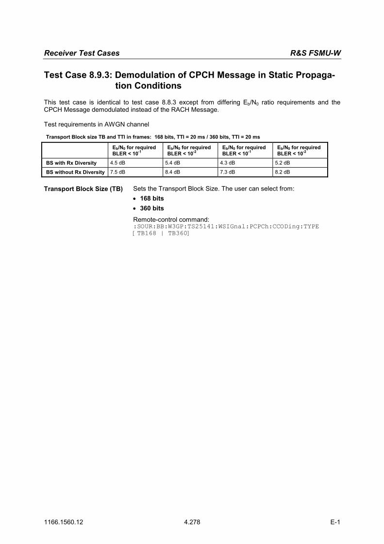
Receiver Test Cases R&S FSMU-W
1166.1560.12 4.278 E-1
Test Case 8.9.3: Demodulation of CPCH Message in Static Propaga-tion Conditions
This test case is identical to test case 8.8.3 except from differing Eb/N0 ratio requirements and the CPCH Message demodulated instead of the RACH Message. Test requirements in AWGN channel
Transport Block size TB and TTI in frames: 168 bits, TTI = 20 ms / 360 bits, TTI = 20 ms
Eb/N0 for required BLER < 10-1
Eb/N0 for required BLER < 10-2
Eb/N0 for required BLER < 10-1
Eb/N0 for required BLER < 10-2
BS with Rx Diversity 4.5 dB 5.4 dB 4.3 dB 5.2 dB
BS without Rx Diversity 7.5 dB 8.4 dB 7.3 dB 8.2 dB
Transport Block Size (TB) Sets the Transport Block Size. The user can select from:
• 168 bits • 360 bits Remote-control command: :SOUR:BB:W3GP:TS25141:WSIGnal:PCPCh:CCODing:TYPE [TB168 | TB360]

R&S FSMU-W Receiver Test Cases
1166.1560.12 4.279 E-1
Test Case 8.9.4: Demodulation of CPCH Message in Multipath Fading Case 3
This test case is identical to test case 8.8.4 except from differing Eb/N0 ratio requirements and the CPCH Message demodulated instead of the RACH Message. Test requirements in fading case 3 channel
Transport Block size TB and TTI in frames: 168 bits, TTI = 20 ms / 360 bits, TTI = 20 ms
Eb/N0 for required BLER < 10-1
Eb/N0 for required BLER < 10-2
Eb/N0 for required BLER < 10-1
Eb/N0 for required BLER < 10-2
BS with Rx Diversity 8.1 dB 9.1 dB 7.9 dB 8.7 dB
BS without Rx Diversity 11.4 dB 12.6 dB 11.3 dB 12.3 dB
Transport Block Size (TB) Sets the Transport Block Size. The user can select from:
• 168 bits • 360 bits Remote-control command: :SOUR:BB:W3GP:TS25141:WSIGnal:PCPCh:CCODing:TYPE [TB168 | TB360]