Embed Size (px)
Citation preview
www.snapav.com Support: 866.838.5052 © 2014 Wattbox™
POWER
WB-RPS10-DC-10A
1. WELCOME TO WATTBOX™WattBox™ Power products are designed specifically for Custom Integrators to offer maximum flexibility for installation. The WattBox RPS DC Series WB-RPS10-DC-10A is a power distribution device offering up to 10 individual DC outputs for rack equipment, eliminating the need for the “wall-wart” power supplies that eat up valuable space. It can be rack, shelf, or wall mounted, and is only 1U tall to save space in the rack.
2. PACKAGE CONTENTS• (1) WB-RPS10-DC-10A• (1) Owner’s Manual• (4) Rubber feet• (11) 2-pole Phoenix connectors • (2) Small rack ears
• (2) Large rack ears• (8) Rack ear screws• (1) Lacing bar and screws• (1) IEC cord clip• (1) Detachable 6-foot IEC power cord
3. KEY FEATURESCompact DesignA 1U chassis design packs 10 DC power supply connections into one neat package. Wall warts and in-line power supplies no longer take up all of the outlet spaces in the rack. Less power cables are needed, so less time is spent organizing and zip-tying to keep the rack neat.
Flexible Mounting OptionsUse the rubber adhesive-back feet for shelf placement or the standard rack ears for rack or wall-mounting. Adjustable depth rack ears are also included to allow for more custom positions.
Power ProtectionOutputs are protected by auto-resetting PTC fuses that will protect the unit from overloaded connections or short circuits. 15 amp Circuit Breaker or Breaker/Switch Surge protection and filtration for 5 and 12V outputs.
Configurable DC Outputs• 3 Position switch for each DC output to select 12v / 5v / AUX voltage• LED feedback for easy setup• 1.3 amps per output• 10 removable Phoenix output connectors
Auxiliary Power Supply• 1 removable input Phoenix connector for DC “AUX” • AC outlet for expansion or AUX power supply
Certifications• UL Listed – 60950-1• FCC Class B
OWNERS MANUALWB-RPS10-DC-10A
™

WB-RPS-12VDC-20A Installation Manual
pg.3pg.2© 2014 Wattbox™
4. CONNECTIONS AND CONTROLS4.1. FRONT PANEL
POWER
WB-RPS10-DC-10A
1
1. Power Status LED IndicatorBlue — Power is connected and Master Power on. Off — Master Power Switch is off or power is disconnected.
4.2. REAR PANEL
12V
5V
AUX
AUXIN
-+ - + + - + - + - + - + - + - + - + - + -
ON
OFF
CAUTION: To avoid damaging connected equipment select the proper output voltage before making connections
12V
5V
AUX
12V
5V
AUX
12V
5V
AUX
12V
5V
AUX
12V
5V
AUX
12V
5V
AUX
12V
5V
AUX
12V
5V
AUX
12V
5V
AUX
51 2 3 4
6 71. Auxiliary Outlet
120V AC outlet for connecting an auxiliary power supply to feed DC voltage to outputs set to “AUX”. This outlet switches on and off with the master power switch.
2. DC Output Voltage Selector Switch 1 - 10Set the switch for each DC output to the desired voltage: 12V DC, 5V DC, or AUX. The switch for each output is located above the 2-pin output connector. The LED will illuminate to indicate the selected voltage for easy identifi-cation:
12V
5V
AUX
AUXIN
-+ - + + - + - + - + - + - + - + - + - + -
ON
OFF
CAUTION: To avoid damaging connected equipment select the proper output voltage before making connections
12V
5V
AUX
12V
5V
AUX
12V
5V
AUX
12V
5V
AUX
12V
5V
AUX
12V
5V
AUX
12V
5V
AUX
12V
5V
AUX
12V
5V
AUX
Switch Position LED Color DC Output VoltageUp Green 12V
Center Yellow 5VDown Blue Max. 24V DC
Note: Set the desired output voltage for each switch BEFORE making connections to the power supply DC out-puts. See instructions on pages 4 and 5.
3. Ventilation FanProvides adequate cooling for the power supply at all times.
4. Detachable Power Cord Inlet with Locking ClipConnect the included cord to provide power from a 15A outlet. Use the locking clip to prevent the cord from being accidentally detached.
5. Master Power SwitchResettable rocker-style breaker switch to control power to the unit.
6. Auxiliary Power Supply InletOptional DC Voltage input for AUX outputs.
7. Detachable 2 Pole Phoenix Connector Outputs 1 - 10Route power to equipment using any solid or stranded conductor sized 12-24 AWG. Each of the ten outputs may be set to their own output voltage.
WB-RPS-12VDC-20A Installation Manual
www.snapav.com Support: 866.838.5052pg.3pg.2
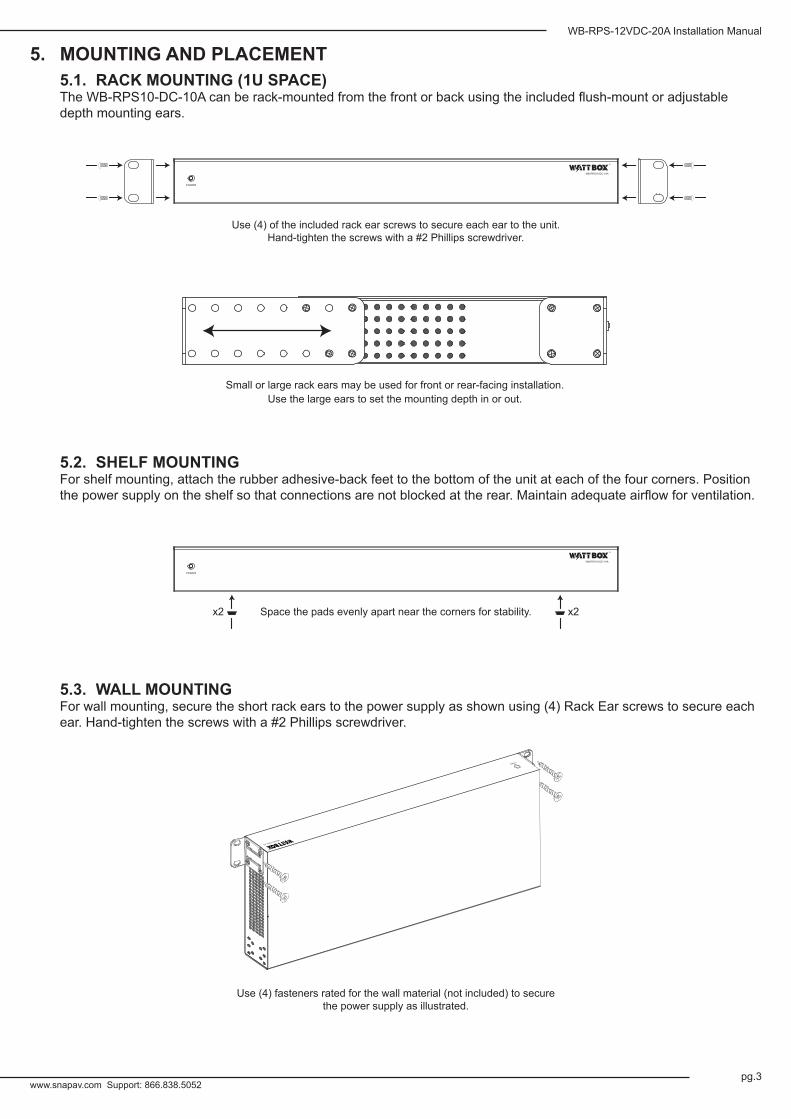
5. MOUNTING AND PLACEMENT5.1. RACK MOUNTING (1U SPACE)The WB-RPS10-DC-10A can be rack-mounted from the front or back using the included flush-mount or adjustable depth mounting ears.
POWER
WB-RPS10-DC-10A
5.2. SHELF MOUNTINGFor shelf mounting, attach the rubber adhesive-back feet to the bottom of the unit at each of the four corners. Position the power supply on the shelf so that connections are not blocked at the rear. Maintain adequate airflow for ventilation.
POWER
WB-RPS10-DC-10A
5.3. WALL MOUNTINGFor wall mounting, secure the short rack ears to the power supply as shown using (4) Rack Ear screws to secure each ear. Hand-tighten the screws with a #2 Phillips screwdriver.
POWER
WB-RPS9-12VDC-10A
Use (4) of the included rack ear screws to secure each ear to the unit. Hand-tighten the screws with a #2 Phillips screwdriver.
Small or large rack ears may be used for front or rear-facing installation.Use the large ears to set the mounting depth in or out.
Space the pads evenly apart near the corners for stability. x2x2
Use (4) fasteners rated for the wall material (not included) to secure the power supply as illustrated.
WB-RPS-12VDC-20A Installation Manual
pg.5pg.4© 2014 Wattbox™
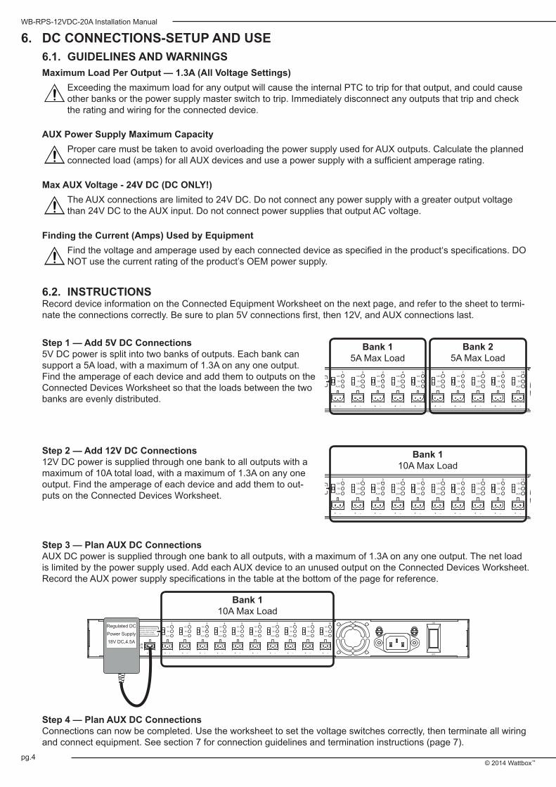
6. DC CONNECTIONS-SETUP AND USE6.1. GUIDELINES AND WARNINGSMaximum Load Per Output — 1.3A (All Voltage Settings)
Exceeding the maximum load for any output will cause the internal PTC to trip for that output, and could cause other banks or the power supply master switch to trip. Immediately disconnect any outputs that trip and check the rating and wiring for the connected device.
AUX Power Supply Maximum CapacityProper care must be taken to avoid overloading the power supply used for AUX outputs. Calculate the planned connected load (amps) for all AUX devices and use a power supply with a sufficient amperage rating.
Max AUX Voltage - 24V DC (DC ONLY!)The AUX connections are limited to 24V DC. Do not connect any power supply with a greater output voltage than 24V DC to the AUX input. Do not connect power supplies that output AC voltage.
Finding the Current (Amps) Used by EquipmentFind the voltage and amperage used by each connected device as specified in the product‘s specifications. DO NOT use the current rating of the product’s OEM power supply.
6.2. INSTRUCTIONSRecord device information on the Connected Equipment Worksheet on the next page, and refer to the sheet to termi-nate the connections correctly. Be sure to plan 5V connections first, then 12V, and AUX connections last.
12V
5V
AUX
AUXIN
-+ - + + - + - + - + - + - + - + - + - + -
ON
OFF
CAUTION: To avoid damaging connected equipment select the proper output voltage before making connections
12V
5V
AUX
12V
5V
AUX
12V
5V
AUX
12V
5V
AUX
12V
5V
AUX
12V
5V
AUX
12V
5V
AUX
12V
5V
AUX
12V
5V
AUX
Bank 15A Max Load
Bank 25A Max Load
Bank 110A Max Load
12V
5V
AUX
AUXIN
-+ - + + - + - + - + - + - + - + - + - + -
ON
OFF
CAUTION: To avoid damaging connected equipment select the proper output voltage before making connections
12V
5V
AUX
12V
5V
AUX
12V
5V
AUX
12V
5V
AUX
12V
5V
AUX
12V
5V
AUX
12V
5V
AUX
12V
5V
AUX
12V
5V
AUX
Step 1 — Add 5V DC Connections5V DC power is split into two banks of outputs. Each bank can support a 5A load, with a maximum of 1.3A on any one output. Find the amperage of each device and add them to outputs on the Connected Devices Worksheet so that the loads between the two banks are evenly distributed.
Step 2 — Add 12V DC Connections12V DC power is supplied through one bank to all outputs with a maximum of 10A total load, with a maximum of 1.3A on any one output. Find the amperage of each device and add them to out-puts on the Connected Devices Worksheet.
Step 3 — Plan AUX DC ConnectionsAUX DC power is supplied through one bank to all outputs, with a maximum of 1.3A on any one output. The net load is limited by the power supply used. Add each AUX device to an unused output on the Connected Devices Worksheet. Record the AUX power supply specifications in the table at the bottom of the page for reference.
12V
5V
AUX
AUXIN
-+ - + + - + - + - + - + - + - + - + - + -
ON
OFF
CAUTION: To avoid damaging connected equipment select the proper output voltage before making connections
12V
5V
AUX
12V
5V
AUX
12V
5V
AUX
12V
5V
AUX
12V
5V
AUX
12V
5V
AUX
12V
5V
AUX
12V
5V
AUX
12V
5V
AUX
Regulated DC Power Supply18V DC,4.5A
Bank 110A Max Load
Step 4 — Plan AUX DC ConnectionsConnections can now be completed. Use the worksheet to set the voltage switches correctly, then terminate all wiring and connect equipment. See section 7 for connection guidelines and termination instructions (page 7).

WB-RPS-12VDC-20A Installation Manual
www.snapav.com Support: 866.838.5052pg.5pg.4
CONNECTED EQUIPMENT WORKSHEETDC
OutputDescription of Connected Equipment
MAXIMUM 1.3A LOAD PER OUTPUT Amps Output Voltage
12V
DC
/AU
X - U
se A
ny O
utpu
t (M
AX
10A
1-10
)5V
DC
BA
NK
1 (M
AX
5A fo
r 1-5
) 1 5 / 12 / AUX
2 5 / 12 / AUX
3 5 / 12 / AUX
4 5 / 12 / AUX
5 5 / 12 / AUX
5V D
C B
AN
K 2
(MA
X 5A
for 6
-10) 6 5 / 12 / AUX
7 5 / 12 / AUX
8 5 / 12 / AUX
9 5 / 12 / AUX
10 5 / 12 / AUX
AUX POWER SUPPLYSpecifications Notes
DC Output Voltage:
Max Amperage:(For AUX IN)

WB-RPS-12VDC-20A Installation Manual
pg.7pg.6© 2014 Wattbox™
7. CONNECTING EQUIPMENT TO DC OUTPUTS7.1. GUIDELINES AND WARNINGSPolarity
Observe proper polarity for the positive (+) and negative (-) conductor when making connections. Some equip-ment could be damaged if polarity is reversed.
7.2. INSTRUCTIONS1. Using the Connections chart as a reference, set each output switch to the required voltage. It is also good practice
to label each wire being connected to the outputs.
12V
5V
AUX
AUXIN
-+ - + + - + - + - + - + - + - + - + - + -
ON
OFF
CAUTION: To avoid damaging connected equipment select the proper output voltage before making connections
12V
5V
AUX
12V
5V
AUX
12V
5V
AUX
12V
5V
AUX
12V
5V
AUX
12V
5V
AUX
12V
5V
AUX
12V
5V
AUX
12V
5V
AUX
2. Terminate the conductors for each output to a 2-pole Phoenix connector (included).
-
¼”
+
3. Double-check each wire and DC output switch and make sure that:• Polarity is correct• No stray conductors touch between + and -• No more than one device is connected per output• All voltage switches are set correctly.
4. Remove the caution label covering the DC outputs on the WB-RPS10-DC-10A chassis and connect the wiring.
5. Use the included lacing bar to secure and organize the wires. Leave slack on each wire so that plugs will not be pulled loose by mistake.
Note: The wire management bar cannnot be used if the AUX power supply outlet is in use.
6. The WB-RPS10-DC-10A may now be powered on. Connect the AC power cord to a 120V AC outlet and turn the master power switch to ON. See the next section for operation and troubleshooting instructions.
CAUTION Select proper output voltage BEFORE making connections CAUTION Select proper output voltage BEFORE making connections
Strip ¼” of insulation and twist stranded conductors.Ensure that no strands touch between conductors.
WB-RPS-12VDC-20A Installation Manual
www.snapav.com Support: 866.838.5052pg.7pg.6
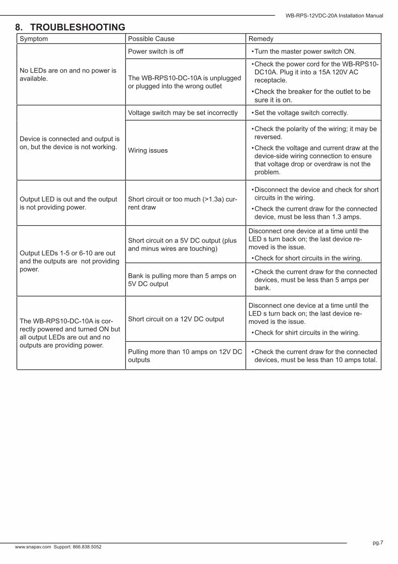
8. TROUBLESHOOTINGSymptom Possible Cause Remedy
No LEDs are on and no power is available.
Power switch is off • Turn the master power switch ON.
The WB-RPS10-DC-10A is unplugged or plugged into the wrong outlet
• Check the power cord for the WB-RPS10-DC10A. Plug it into a 15A 120V AC receptacle.
• Check the breaker for the outlet to be sure it is on.
Device is connected and output is on, but the device is not working.
Voltage switch may be set incorrectly • Set the voltage switch correctly.
Wiring issues
• Check the polarity of the wiring; it may be reversed.
• Check the voltage and current draw at the device-side wiring connection to ensure that voltage drop or overdraw is not the problem.
Output LED is out and the output is not providing power.
Short circuit or too much (>1.3a) cur-rent draw
• Disconnect the device and check for short circuits in the wiring.
• Check the current draw for the connected device, must be less than 1.3 amps.
Output LEDs 1-5 or 6-10 are out and the outputs are not providing power.
Short circuit on a 5V DC output (plus and minus wires are touching)
Disconnect one device at a time until the LED s turn back on; the last device re-moved is the issue.• Check for short circuits in the wiring.
Bank is pulling more than 5 amps on 5V DC output
• Check the current draw for the connected devices, must be less than 5 amps per bank.
The WB-RPS10-DC-10A is cor-rectly powered and turned ON but all output LEDs are out and no outputs are providing power.
Short circuit on a 12V DC output
Disconnect one device at a time until the LED s turn back on; the last device re-moved is the issue.• Check for shirt circuits in the wiring.
Pulling more than 10 amps on 12V DC outputs
• Check the current draw for the connected devices, must be less than 10 amps total.

11. WARRANTY
5year
5-YEAR LIMITED WARRANTYThis WattBox™ product has a 5-Year Limited Warranty. The warranty includes parts and labor repairs on all components found to be defective in material or workmanship under normal conditions of use. This warranty shall not apply to products that have been abused, modified, disassembled or improperly installed. Products to be repaired under this warranty must be returned to WattBox™ or a designated service center with prior notification and an assigned return authorization number (RA).
9. IMPORTANT SAFETY INSTRUCTIONSWARNING: To reduce the risk of fire or electric shock, do not expose this apparatus to rain or moisture. Do not remove cov-er. No user serviceable parts inside. Refer servicing to qualified service personnel.
1. Read and follow all instructions and warnings in this manual. Keep for future reference.2. Do not use this apparatus near water.3. Clean only with a dry cloth.4. Do not block any ventilation openings. Install according to manufacturer’s instructions.5. Do not install near any heat sources such as radiators, heat registers, stoves or other apparatus (including amplifiers)
that produce heat.6. Do not override the safety purpose of the polarized or grounding-type plug. A polarized plug has two blades — one wider
than the other. A grounding type plug has two blades and a third grounding prong. The wide blade or the third prong is provided for your safety. If the provided plug does not fit into your outlet, consult an electrician for replacement of the obsolete outlet.
7. Protect the power cord from being walked on or pinched particularly at plug, convenience receptacles, and the point where it exits from the apparatus.
8. Only use attachments/accessories specified by the manufacturer.9. To completely disconnect this equipment from the AC mains, disconnect the power supply cord plug from the AC
receptacle.
10. This is CLASS II apparatus with double insulation, and no protective earth provided.
CAUTIONCAUTION: TO REDUCE THE RISK OF ELECTRICAL SHOCK.
DO NOT REMOVE COVER. NO USER SERVICEABLE PARTS INSIDE.
REFER SERVICING TO QUALIFIED SERVICE PERSONNEL.
The lightning flash with arrowhead symbol, within an equilateral triangle, is intended to alert the user to the presence of un-insulated dangerous voltage within the product’s enclosure that may be of sufficient magnitude to constitute a risk of electric shock to persons.
The exclamation point within an equivalent triangle is intended to alert the user to the presence of important operating and maintenance (servicing) instructions in the literature accompanying the appliance.
10. SPECIFICATIONS Input
Input Voltage 120VAC/60HzCurrent Rating 11APower Rating 1320 W
AC Input IEC C-14Power Cord Length 6 Feet
Surge Protection 2160 Joules
OutputOutput Voltage (Selectable) 5VDC, 12VDC, AUX
Output Current 10AChannels 10
Max Output Current per Channel 1.3A
Overload Protection PTCAUX IN DC INPUT ONLY
Maximum AUX Input 24VDC 2AAUX AC Outlet (Front Panel) 120VAC, 11A
Cooling Fan YesCertifications UL, cUL 60950-1
Dimensions 19"W x 1.75"H x 8.25"DWeight 7.75 lbs. 140523-1500
© 2014 Wattbox™
pg.8