Embed Size (px)
Citation preview

1

WAYS AND TECHNOLOGIES AVAILABLE FOR OPTIMUM
UTILIZATION
2

DEVELOPMENT OF GEOPOLYMER CONCRETE PRODUCTS
Dr. C. Antony JeyaseharProfessor of Civil and Structural Engineering
Dr. S. ThirugnanasambandamAssociate Professor of Civil and Structural Engineering.
Annamalai UniversityAnnamalainagar-608002

Current Scenario in Concrete ProductionDemand increases vastly for raw materials.
Difficult to produce concrete due to continuous fluctuations in
availability of raw materials.
Frequent hikes in cost prices of the raw materials of concrete due
to their inconsistent availability.
Contributing to global warming by using cement as a raw material
for concrete.
Need for an alternative raw materials for making concrete - eco
friendly. 4

Ordinary Portland Cement – Frontline Supporter of Global Warming
Deadly Consumer of natural resources.
Creator of severe causes for environment imbalance.
Important contributor to global warming by emitting more
CO2 to atmosphere.
Intakes high amount of energy for production.
Utiliser of water for cooling at the stage of clinker.
Solution ?????5

Cement ProductionProcess of Manufacturing
of CementEmission of Carbon
dioxide
6

6
Gas pipeline from Iran, discouraged by U.S.
Coal supplies for 200 years, but high/ash, low
calorie value
Oil discovery by Cairn Energy in 2004; India’s demand will outstrip
supply
Gas discovery by Reliance in 2003 but
will service only fraction of India’s
power needs
Tarapur- India’s “civilian” nuclear reactor requires
refueling
Kakrapar- World’s first thorium-based nuclear
reactor
Gas pipeline from Turkmenistan, through
Pakistan, but questionable reserves
Gas pipeline from Myanmar through Bangladesh discouraged by U.S.
Hydro-Electric Dam at Narmada constrained by
problems with environment
Ron Somers, (U.S.-India Business Council), India Energy Conference,
Houston, Jun 2006
India’s Energy Security ChallengeIndia’s Energy Security Challenge

8
Global CO2 emissionsWorld Carbon Dioxide Emission in Million Metric Tons (1980 to 2050*)
0
10,000
20,000
30,000
40,000
50,000
60,000
70,000
1980 1990 2003 2010 2020 2025 2050
65 Billion Tons by 2050
Mill
ion
Met
ric T
ons
Boston Analytics Research1. Energy Information Administration
(http://www.eia.doe.gov)
Year
• Use of geopolymer concrete reduces the release of CO2 in the atmosphere

Available Resources
We cannot continue to throw awaymountains of fly ash and slagBut will there always be suchmountains?
9

Re-Arranging the Equation
Power Generation Refinery/Chemical industryCement Production 10

Re-Arranging the Equation
+
11

Necessity of Geopolymer ConcreteTo produce Eco-Friendly concrete.
To reduce the utilisation of Ordinary Portland Cement.
To reduce the hazardous effects of industrial by-products by using themin making of concrete.
To reduce the mining of natural resources like limestone, clay etc.,
To save the loss of high energy used in cement industries.
To minimise the high utilisation of water during and after the productionof concrete.
To reduce global warming as much as possible.
To gift our future generations a safe planet.12

Geopolymers The term geopolymer was coined by Joseph Davidovits in 1978.
The geopolymers are mineral binder with chemical composition similar to
zeolites but with amorphous microstructure.
Geeopolymer was also chemically designated as ‘Poly(sialate)’ by Joseph
Davidovits.
Sialate is an abbreviation for silicon – oxo – aluminate.
Geopolymers are generally based on silico – aluminate.
Empirical formula for Poly(sialates) is given by : Mn (-(SiO2)z – AlO2)n .
wH2O
M = Monovalent cation such as Potassium or Sodium.
n = Degree of polycondensation and z = 1, 2,3 or higher upto 32. 13

Main Constituents of Geopolymers The significant constituents of geopolymers are the source
material and the alkaline activator solution.
The source materials should be rich in Silicon (Si) andAluminium (Al).
The source materials are available naturally in the form ofminerals and alternatively in the form of by-products.
Natural minerals : Kaolinite, clays, micas, spinel and etc.,
By-products : Fly ash, silica fume, slag, rice husk ash, red mudand etc.,
The alkaline solutions are from alkali soluble metals usuallysodium or potassium based. 14

Materials used for Geopolymer Concrete
Among all other source materials low calcium fly ash is mainlyused all around world.Low calcium fly ash.
A by-product obtained from burning of coal from the thermalpower plants.
Ground Granulated Blast Furnace Slag (GGBS).
A by-product obtained from steel industries.
Alkaline solutionSodium hydroxide or Potassium hydroxide.Sodium silicate solution or Potassium silicate solution.
Coarse Aggregate: Crushed stones /gravels.
Fine Aggregate : River sand / M Sand. 15

Applications of Geopolymers based on their Si : Al ratio
Si:Al ratio Applications
1- Can be used to make bricks.- Can be used for producing ceramics.- Can be used as fire protection where there is a frequent
chances of fire accidents.2 - Low CO2 cements and concretes.
- Radioactive and toxic waste encapsulation.3 - Fire protection fibre glass composite.
- Foundry equipment’s – Heat resistant composites, 200o C to 1000o C.
- Tooling for aeronautics titanium process.>3 - Sealants for industry, 200o C to 600o C.
- Tooling for aeronautics SPF Aluminium.20 -35 - Fire resistant and heat resistant fibre composites
16

Materials used for Geopolymer Concrete
17

CHEMICAL COMPOSITION OF CEMENT AND FLY ASH
Materail SiO2 Al2O3 Fe 2O3 CaO Mgo SO3 Na2O
Cement 19.33 5.66 2.66 63.07 0.36 3.38 0.14
Flyash 66.61 27.57 3.14 1.32 1.36 - -

Preparation of Alkaline SolutionThe alkaline solution should be prepared 24 hours prior to casting of
GPC Concrete.
Step 1 : The required amount of NaOH pellets are mixed with requiredamount of H2O.
Step 2 : Na2SiO3 solutions are mixed with NaOH solution.
Step 3 : The solution is mixed thoroughly and leave it for 24 hours.
The solution is kept idle for 24 hours is to developing the polymerisationprocess.
After 24 hours the alkaline solution is ready for making geopolymerconcrete.
In place of NaOH pellets and Na2SiO3 solutions, KOH pellets andK2SiO3 solution may be used for making alkaline solution. 19

Preparation of Alkaline Solution
20

Mixture Proportions of Geopolymer ConcreteThe main difference between OPC concrete and geopolymer concrete is the
binder.Fly ash(silicon and aluminium oxides) + alkaline solution → geopolymerpaste.Geopolymer paste binds the fine aggregate, coarse aggregate, other
unreacted materials.75 - 80 % of mass filled by aggregates (similar to cement concrete).The mixture can be designed using the same designing tool used for OPC
concrete.The alkaline solution influences the strength of geopolymer concrete.The concentrations of alkaline solution : 8M – 16M.8M of alkaline solution is sufficient to get concrete with normal strength.Water to geopolymer solids ratio influences the strength and workability of
the GPC. 21

Mixing & Casting of Geopolymer ConcreteA pan mixer was used for mixing of geopolymer concrete.The aggregates were prepared in saturated-surface-dry (SSD)
conditions.Step 1 : Fly ash was first mixed (dry) together with GGBS in pan
mixer for 2 minutes.Step 2 : Sand was placed in the pan mixer and the mix is continued
for another 2 minutes.Step 3 : Coarse aggregate is added to the mix and allowed to mix
for another 2 minutes.Step 4 : Finally the alkaline solution was added and the mix was
continued for 4 minutes.Step 5 : The workability of the geopolymer concrete should be
tested.Step 6 : The Geopolymer concrete can be cast in required moulds
to get specimens.22

Mixing of Geopolymer Concrete
23

Curing of Geopolymer ConcreteTypes of curing used:
Steam curing or hot air oven curing.
Ambient Curing. (Sunlight/room temperature)
Steam curing is required when GGBS is not added with fly ash.
Rest Period: 1 day.
Curing Period : 24 hours (1 day).
Curing temperature : 60oC (Steam/Hot air oven curing).
If GGBS is added ambient curing is sufficient to attain required
strength. 24

Steam Curing Chamber-GPC Concrete
Steam Curing Chamber-Open View Steam Curing Chamber-Closed View25

CASE STUDY - IM 20 grade concrete obtained using IS:10262-2009 was used (1:1.7:3.1) with a partialmodification of replacement of cement & water by fly ash & alkaline solutions.
Sl. No.
Mix Ratio Flyashkg.
Fine Agg. kg.
Coarse Agg. kg.
NaOH Solution Sodium Silicate
kg.
Sodium Silicate / Sodium
Hydroxide
(Sodium Silicate + Sodium Hydroxide)
/ FlyashMasskg.
Molarity
1 1:1:7:3.1 414 704 1283 17.02 8 M 133 2.5 0.45
Constituents of geopolymer concrete (Per 1m3)
Sl. No. Mix Ratio Molarity of NaOH
Solution
Slump mm
Curing Method
Curing Time
Curing Temp
Average Comp.
Strength N/mm2
1 1:1.7:3.1 8 M 120 steam 24 Hours 60ºC 30.702 1:1.7:3.1 10 M 105 steam 24 Hours 60ºC 32.53 1:1.7:3.1 12 M 85 steam 24 Hours 60ºC 37.5
Workability and strength properties

27
Sl. No.
Molarities of NaOH
AAS/Fly ash Ratio
Cube compressive
strength (N/mm2)
Cube Tensile
strength (N/mm2)
Cylinder compressive
strength (N/mm2)
Cylinder split tensile
strength (N/mm2)
123
8M10M12M
0.4049.5048.3346.72
9.1810.228.63
36.1835.8334.92
4.664.133.96
456
8M10M12M
0.4550.0249.1347.24
9.3710.568.69
37.3636.2335.67
5.134.784.02
789
8M10M12M
0.5052.0850.7349.26
9.8610.888.93
38.7237.0036.45
5.484.974.24
101112
8M10M12M
0.5549.7548.6347.84
9.0210.138.09
36.2735.5436.13
4.584.173.85
Compressive and Tensile Strength for Cubes and Cylinders
CASE STUDY – IIA mix ratio 1:1.3:2.7 (1 fly ash: 1.3 fine aggregate: 2.7 coarse aggregate)had been obtained for a cube compressive strength of 40 N/mm2 . In thisstudy, various concentrations of NaOH solutions 8M, 10M and 12M wereused along with different Alkali Activator Solution (AAS) / fly ash ratios 0.40,0.45, 0.50 and 0.55.

28
Geopolymer concrete Beams Totally five beams were cast and tested in the laboratory over an
effective span of 3000 mm.
Four geopolymer concrete beams were tested until failure; theremaining one beam was used as a Reinforced Cement Concrete(RCC) control specimen.
The beams were designed as under reinforced section, reinforcedwith 2-Y12 at bottom, 2-Y10 at top using 6 mm diameter stirrups at50 mm c/c and Fe 415 grade steel was used.
The geopolymer concrete mix proportion was 1:1.3:2.70 with differentAAS/fly ash ratio 0.4, 0.45, 0.5 and 0.55. For RCC beam, OrdinaryPortland Cement (OPC) 53 grade, natural river sand conformingZone III (IS 383-1970) and coarse angular aggregate of 20 mm wereused as the concrete ingredients.
The specimens (with the mould) were cured using steam curing.

Geopolymer concrete Beams
Testing of Geopolymer BeamsCrack pattern on Geopolymer
Beams
29
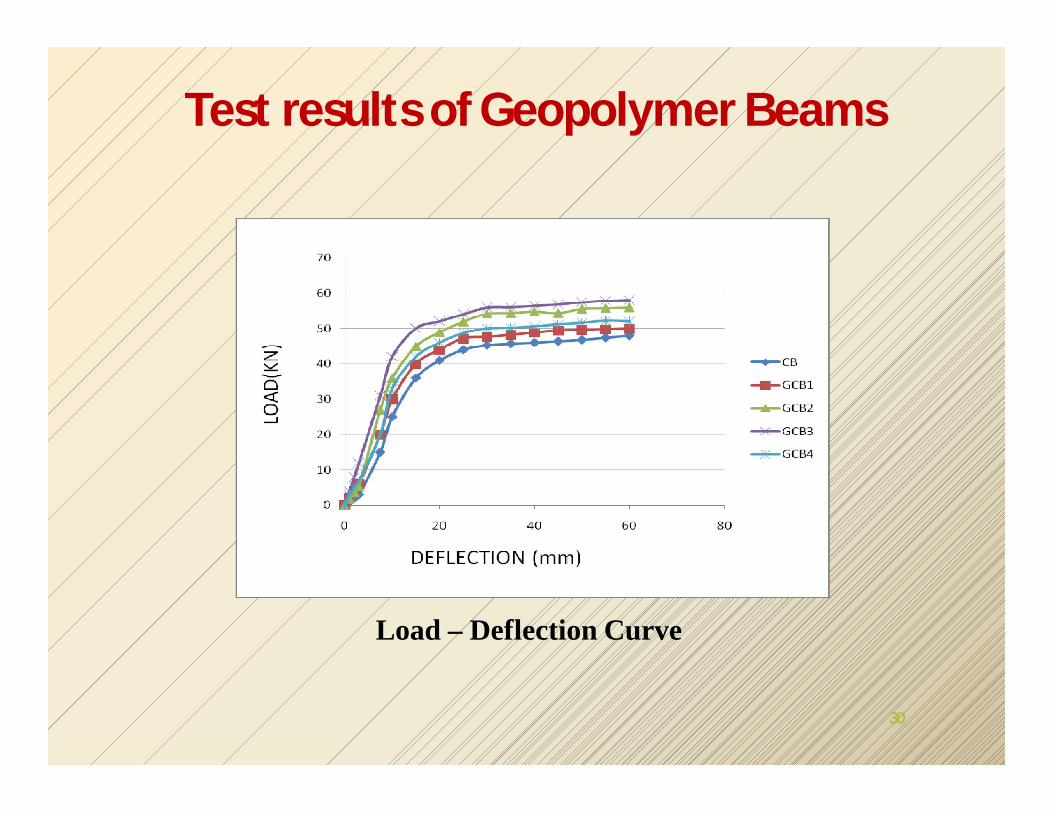
Test results of Geopolymer Beams
Load – Deflection Curve
30

Developments in Geopolymer concretePost –Tensioned of Geopolymer Beams
Arrangement of Duct before Casting
Casting of Post-Tensioned Beam
Crack Pattern on GPC Post – Tensioned Beam 31

Test results of Post- Tensioned Geopolymer Beams
Load – Deflection Curve for OPC Post – Tensioned Beam
Load – Deflection Curve for GPC Post-tensioned Beam
32

Developments in Geopolymer concrete
Pre –tensioning of geopolymer sleepers
Pre – tensioned geopolymer sleepers after casting
33

Developments in Geopolymer concrete
Testing of Pre- tensioned geopolymer railway sleepers
Crack pattern of Pre – tensioned geopolymer railway sleepers34

Test results of Pre- Tensioned Geopolymer Railway Sleepers
Load – Deflection Curve for OPC Pre – Tensioned Sleepers
Load – Deflection Curve for GPC Pre-Tensioned Sleepers
35
36
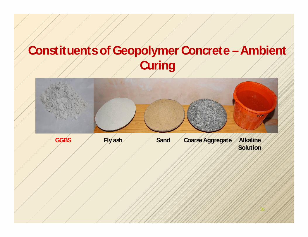
GGBS Fly ash Sand Coarse Aggregate AlkalineSolution
Constituents of Geopolymer Concrete – Ambient Curing

Ambient Curing of Geopolymer ConcreteThe Ordinary Portland Cement concrete needs water curing during
hydration process.
In GPC the water is expelled during polymerization process and there is
no need for water curing.
So ambient curing is opted for GPC and it was proved that ambient
curing is sufficient for GPC.
Ambient curing has more benefits than any other curing methods.
The GPC cubes were cast and cured in ambient temperature for 24 hours.
The day time temperature varies between 30 to 35 degree Celsius and
night time temperature varies between 25 to 30 degree Celsius.37

Ambient Curing of GPC Concrete
Casting of Geopolymer Concrete Cube Specimens
38
Ambient curing of cube specimens

39
Reinforcement Grills for Beams
Casting of Geopolymer Concrete Beam Specimens

40
Ambient curing of Beams Specimens

41
Crack Pattern of Conventional Cement Concrete Beam
Crack Pattern of Geopolymer Concrete Beam

42
0
5
10
15
20
25
30
35
40
45
50
0 10 20 30 40 50 60 70 80 90
Loa
d in
kN
Deflection in mm
CB-I GB-I
Comparison of Load Deflection Behaviour of Conventional Cement Concrete and GPC Beams
Sl. No. Beam Designation
Load at Different Stage (kN)Deflection (mm)
First Crack Yield Ultimate First
Crack Yield Ultimate
1 CBI 10 25 42.5 6.2 22.4 793 GBI 12.5 27.5 45 4 24.6 82
Test Results of Concrete and GPC Beams

Railway Sleepers
43
Pretensioning of Strands Casting of GPC Sleeper De Tensioning of Strands

44
Ambient Curing of GPC Sleeper
Crack Pattern of GPC Sleeper

45
Load - Deflection curve for Cement Concrete and GPC Sleepers
Cement Concrete Sleeper Geopolymer Concrete Sleeper
First crack Load in kN
Yield Load in
kN
Ultimate stageFirst
Crack Load in
kN
Yield Load in kN
Ultimate stage
Load in kN Deflection in mm
Load inkN
Deflection in mm
90 123 290 32 60 182 320 49
Experimental Results of Railway Sleepers

Ferrogeopolymer – Grill Mesh
Ferrogeopolymer Water Pipes After Casting
46
Ferrogeopolymer pipes

Peak load = 0.5 kNYield stress = 390 MPaUltimate tensile stress = 500 MPa
Tensile Strength Test
Expended Wire Mesh
Welded Wire Mesh

Testing of ferrogeopolymer water pipes
Ferrogeopolymer water pipes crack pattern
48
Sl. No Type of Pipe Load at First Crack (kN)
Ultimate Load (kN)
Crack Width(mm)
1 Ferrocement pipe 10 40 0.01
2 Ferrogeopolymer pipe 22.5 50 0.01
3 Commercial pipe 5 8.3 0.01
Test Results of pipes

Developments in Geopolymer concrete
Ferro-geopolymer channels for Roofing Systems.
Ferro-geopolymer channels for roofing system 49

50
Load-Deflection Curve of Ferrocement, Ferrogeopolymer Channel
Sl. No. Ferrocement Channel Ferrogeopolymer Channel1 First crack load = 4.167 kN First crack load = 4.99 kN2 Ultimate load = 25.5 kN Ultimate load = 27.50 kN3 Deflection at first crack load =
1.8 mm Deformation at first crack load = 3.4 mm
4 Ultimate deflection = 29mm Ultimate deflection = 58mm
Test Results of Channels

Developments in Geopolymer concreteFerro-geopolymer
Dome after Casting
Crack Patterns Ferrogeopolymer
DomeTesting of Ferro-
geopolymer Dome
51

52
Des
igna
tion
of
Dom
e
Firs
t C
rack
L
oad(
kN)
Ulti
mat
e L
oad
(kN
) Displacement at First Crack Load (mm)
Displacement at Ultimate Load (mm)
HD1 VD2 HD3 VD4 HD1 VD2 HD3 VD4FCD1 60 95 0.15 1.99 0.37 0.39 0.55 3.01 0.44 0.69
FGPD1 45 160 0.08 1.68 0.39 0.97 0.48 4.92 1.69 5.47
Test Results of Domes
HD1 – Dial gauge placed horizontally at 150mm from baseVD2 – Dial gauge placed vertically at 300mm from baseHD3 – Dial gauge placed horizontally at 250mm from baseVD4 – Dial gauge placed vertically at 400mm from base
Designation of Dome Service Load (kN) Energy Absorption
(kNmm) Ductility Ratio
FCD1 57.79 137.5 1.76
FGPD1 98.49 420.57 5.6
Service Load, Energy Absorption and Ductility Ratio of Domes

Route to Geopolymer Bricks
53
CLAY BRICKS (Firing method)
FLY ASH BRICKS (Cementing method)
GEOPOLYMER BRICKS (Geopolymer method)
FLY ASH BRICKS CLAY BRICKS

Geopolymer Bricks
54
Sodium hydroxide Sodium silicate Activated solution Fly ash and GGBS
Bricks in Mould Curing
Compression TestingWater Absorption Testing Acid Resistance Testing
Fine Aggregate

Geopolymer Bricks
55
Sl. No. NaOH FA : GGBS Curing
Average Compressive
Strength (MPa)
1 6M 50 : 50 Oven 16.50
2 6M 50 : 50 Ambient 14.80
STRENGTH OF GEOPOLYMER BRICKS
SI. No
Types of BricksAverage Percentage of Water
Absorption (%)
1 Geopolymer Brick 4.06
2 Clay Brick 15.29
WATER ABSORPTION OF GEOPOLYMER BRICKS
ACID RESISTANCE TEST RESULT
Sl. No.
Types of Brick
Loss of Weight(%)
Loss of Compressive Strength (%)
H2SO4(1%)
HCL(3%)
H2SO4(1%)
HCL(3%)
1 Conventional 2.40 4.42 23.61 24.05
2 Geopolymer 2.26 1.02 18.96 5.07

56
Comparing the Geopolymer Brick and Conventional Bricks
Sl.No Type of bricksWater
absorption (%)
As per IS Code[ IS: 1077:1992 ]
Recommendation
1 Convention Bricks 15.3 1077:1992 ] Maximum allowable water absorption percentage of Brick : 20 %2 Fly ash Bricks 15
3 Geopolymer Bricks 4
Sl.No.
Concentration of
NaOH
FA : GGBS%
CuringAverage
Compressive Strength
(N/mm2)
As per IS Code [ IS: 3495:1992 ]
Recommendation
1 6M 50 : 50 Ambient 14.80minimum Strength of
Brick : 3.5 N/mm2
Strength of Geopolymer Brick

57
Geopolymer Clay Bricks
Average compressive strength of geopolymer clay brick is 6.88 MPa.

58
Types of Blocks% of Weight Loss % of Compressive Strength
LossHCL(3%) H2SO4(1%) HCL(3%) H2SO4(1%)
Conventional blocks 1.88 0.97 16.34 21.20
Geopolymer blocks 0.47 0.35 5.01 5.28
TYPES OF BLOCKS
PERCENTAGE INCREASE IN WATER
Conventional blocks 6.059Geopolymer blocks 1.285
Acid Resistance Test
Water Absorption Test
GEOPOLYMER CONCRETE HOLLOW BLOCKS

GEOPOLYMER CONCRETE USING M SAND

Mix Proportioning of M30 & M40 Grade Conventional Concrete
Grade of Concrete M 30 M 40
Mix Proportion 1 : 2.11 : 3.37 1 : 1.63 : 2.64
Cement(kg/m3) 350 430
Fine Aggregate(kg/m3) 737.568 699.660
Coarse Aggregate(kg/m3) 1178.064 1136.430
Water Content(kg/m3) 165 165
W/C Ratio(%) 0.47 0.38
Slump(mm) 60 70
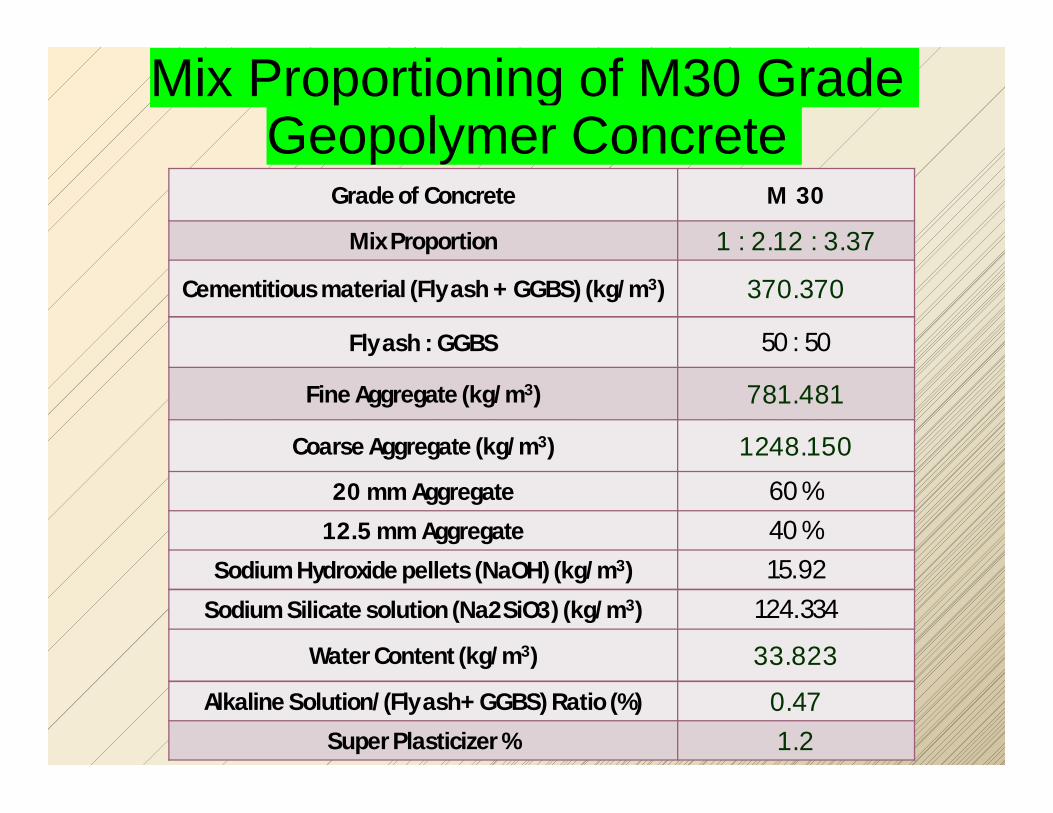
Mix Proportioning of M30 Grade Geopolymer Concrete
Grade of Concrete M 30
Mix Proportion 1 : 2.12 : 3.37
Cementitious material (Fly ash + GGBS) (kg/m3) 370.370
Fly ash : GGBS 50 : 50
Fine Aggregate (kg/m3) 781.481
Coarse Aggregate (kg/m3) 1248.150
20 mm Aggregate 60 % 12.5 mm Aggregate 40 %
Sodium Hydroxide pellets (NaOH) (kg/m3) 15.92
Sodium Silicate solution (Na2SiO3) (kg/m3) 124.334
Water Content (kg/m3) 33.823
Alkaline Solution/(Fly ash+ GGBS) Ratio (%) 0.47Super Plasticizer % 1.2
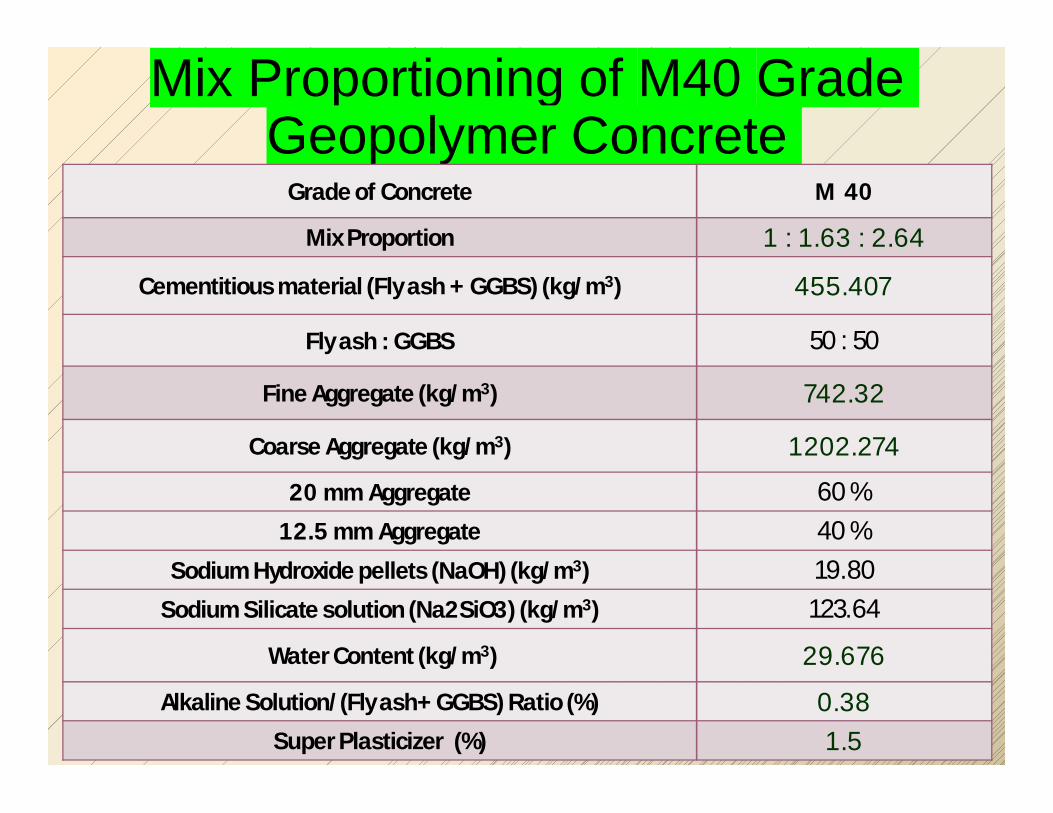
Mix Proportioning of M40 Grade Geopolymer Concrete
Grade of Concrete M 40
Mix Proportion 1 : 1.63 : 2.64
Cementitious material (Fly ash + GGBS) (kg/m3) 455.407
Fly ash : GGBS 50 : 50
Fine Aggregate (kg/m3) 742.32
Coarse Aggregate (kg/m3) 1202.274
20 mm Aggregate 60 % 12.5 mm Aggregate 40 %
Sodium Hydroxide pellets (NaOH) (kg/m3) 19.80Sodium Silicate solution (Na2SiO3) (kg/m3) 123.64
Water Content (kg/m3) 29.676
Alkaline Solution/(Fly ash+ GGBS) Ratio (%) 0.38Super Plasticizer (%) 1.5
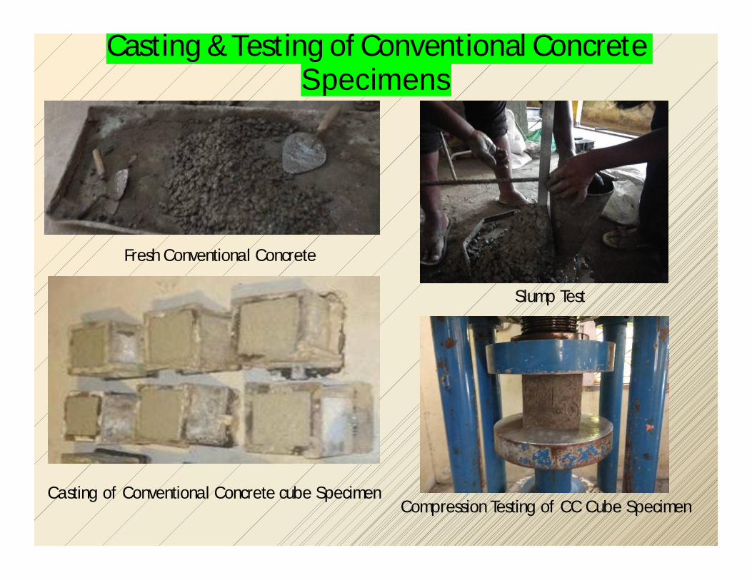
Casting & Testing of Conventional Concrete Specimens
Fresh Conventional Concrete
Slump Test
Casting of Conventional Concrete cube Specimen Compression Testing of CC Cube Specimen
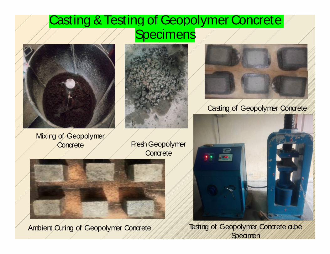
Casting & Testing of Geopolymer Concrete Specimens
Fresh Geopolymer Concrete
Casting of Geopolymer Concrete
Testing of Geopolymer Concrete cube Specimen
Ambient Curing of Geopolymer Concrete
Mixing of Geopolymer Concrete

Compressive Strength ofConventional Concrete Cube Specimen
Grade of Concrete M 30 M 40
7 days StrengthN/mm² 31.67 35.73
14 days StrengthN/mm² 35.73 43.20
28 days StrengthN/mm² 38.82 48.41

Compressive Strength of M30 Grade Geopolymer Concrete Cube Specimen
Grade of Concrete M30
3 Days Compressive Strength of GPC with River Sand
N/mm²39.50
3 Days Compressive Strength of GPC with M - SandN/mm²
43.77

Compressive Strength of M40 Grade Geopolymer Concrete Cube Specimen
Grade of Concrete M40
3 Days Compressive Strength of GPC with River Sand
N/mm²55.03
3 Days Compressive Strength of GPC with M - SandN/mm²
61.82

M30 Grade Concrete
Comparison of M30 concrete CC vs GPC(S) vs GPC(M-S)

M40 Grade Concrete
Comparison of M40 concrete CC vs GPC(S) vs GPC(M-S)

Environmental Benefits of Geopolymer Technology
Usage of industrial by-products in concrete imparts better value
addition to these materials.
Safe disposal of hazardous industrial by-products like fly ash.
Usage of natural recourses like limestone and clay can be
significantly reduced.
The agricultural lands can be saved from being filled up with fly
ash.
Reduction of high energy loss and water loss.
Global warming can be reduced. 70

Economic Benefits of Geopolymer Technology
Reduction upto 10-30 % in the cost of fly ash based geopolymer
concrete.
Savings in cost of expensive moulds at precast element industries.
Savings in time as the geopolymer concrete attains its full
strength in one day.
It is possible to increase the construction rate more faster by
implementing geopolymer technology.
Water curing is completed eradicated in the geopolymer concrete
results in saving the cost of water. 71

Conclusions Low-calcium fly ash-based geopolymer concrete has an excellent
compressive strength and is suitable for structural applications.
The Geopolymer concrete can be used as an appropriate alternative to
OPC Concrete.
72


![ACOUSTIC STUDIES IN TERNARY LIQUID SYSTEMS OF … · Department of Physics [D.D.E], Annamalai University, Annamalainagar – 608 002, India. * E-mail: thirumaran64@gmail.com ABSTRACT](https://img.dokumen.tips/doc/110x75/5fe7e789321fe84102181747/acoustic-studies-in-ternary-liquid-systems-of-department-of-physics-dde-annamalai.jpg)