Embed Size (px)
Citation preview

34 IEEE JOURNAL ON SELECTED AREAS IN COMMUNICATIONS, VOL. 37, NO. 1, JANUARY 2019
Waveform Design for Fair Wireless Power TransferWith Multiple Energy Harvesting Devices
Kyeong-Won Kim, Hyun-Suk Lee , and Jang-Won Lee , Senior Member, IEEE
Abstract— In this paper, we study the waveform design in thewireless power transfer (WPT) system with multiple receivers.In the multi-receiver WPT system, due to the severe powerattenuation of RF signals according to the distance and theheterogeneity in the energy harvesting capability, there existssevere unfairness in energy harvesting among receivers at dif-ferent distances from the transmitter and/or different energyharvesting capabilities. Hence, alleviating unfairness in energyharvesting among receivers is one of the critical challenges inthe multi-receiver WPT system. To tackle this challenge in asystematic way, we consider the fairness in our waveform designapplying the α-proportional fairness. With the analysis of therectenna circuit, we derive the output dc voltage and power of therectifier in closed forms. Thereby, we formulate an optimizationproblem to design the waveform for fair WPT. The problemis shown to be a non-convex optimization problem, which ishard to solve in general. However, with proper approximations,we convert it into a convex optimization problem that can besolved easily and obtain the waveform for fair WPT. Numericalresults show that our designed waveform makes receivers harvestenergy fairly and can control the degree of the fairness easily.
Index Terms— Wireless power transfer, waveform design, fair-ness, non-linear rectifier, multi-receivers.
I. INTRODUCTION
W ITH the advent of the Internet of Things (IoT) tech-nology, it is expected that massive number of IoT
devices will be deployed in the near future. However, it ispractically impossible to maintain such a large number of IoTdevices by periodically charging or exchanging their batterieswith manpower. Thus, it is imperative to develop a newpower-provisioning technology for IoT devices. Recently, far-field Wireless Power Transfer (WPT) has emerged as one ofthe promising candidates for such a new power-provisioningtechnology since it has many advantages such as long chargingdistance, small form factor of the receiver, mobility support,the compatability with the communication system [1]–[4].
Although WPT has many advantages, it has critical chal-lenges due to the severe power attenuation of radio fre-quency (RF) signals according to the distance between
Manuscript received March 15, 2018; revised July 6, 2018; acceptedSeptember 6, 2018. Date of publication September 28, 2018; date of currentversion December 14, 2018. This work was supported by the SamsungResearch Funding Center of Samsung Electronics under Project SRFC-IT1701-13. (Corresponding author: Jang-Won Lee.)
The authors are with the Department of Electrical and ElectronicEngineering, Yonsei University, Seoul 03722, South Korea (e-mail:[email protected]; [email protected]; [email protected]).
Color versions of one or more of the figures in this paper are availableonline at http://ieeexplore.ieee.org.
Digital Object Identifier 10.1109/JSAC.2018.2872311
transmitter and receiver. Moreover, since there exist the regu-lations on the maximum transmit power and the RF exposuredue to safety issues, receivers far away from the transmittermay not be able to charge their battery sufficiently using WPT.Hence, most of researches on WPT have tried to improvethe RF-to-direct current (DC) conversion efficiency of therectenna, which consists of receiver antennas and rectifiers,to increase the DC power of the rectenna without the increasein transmission power.
In early researches on WPT, it has been shown thatthe RF-to-DC conversion efficiency is highly dependant onthe captured power density at the received antenna [5]–[7], theaccuracy of the impedance matching between antenna and rec-tifier [8], [9], and the circuit design of the rectifier [10]–[12].Hence, most of the early researches have confined to the circuitdesign of the rectenna. However, recently, it has been shownthat the non-linear behavior of a diode in the rectifier affectsthe RF-to-DC conversion efficiency. Accordingly, the non-linear behavior of the dioide is explicitly considered forvarious WPT researches [13]–[24]. Especially, it has beendemonstrated that the waveform design for the transmit signalof WPT is also a crucial factor for the RF-to-DC conversionefficiency due to the non-linear behavior of a diode in therectifier [17]–[24]. Hence, the researches on the waveformdesign for the transmit signal have emerged in the WPTliterature.
The effects of the waveform of the transmit signal toRF-to-DC conversion efficiency were studied in [17]–[20].Along with the analysis of the non-linear behavior andtopology of the rectifier, Boaventura et al. [17] showed thatthe choice of the waveform of the transmit signal highlyaffects the RF-to-DC conversion efficiency. Through theanalysis and simulation results, Boaventura and Carvalho [18]showed that a multisine signal, which consists of multiplesinewaves, has a higher RF-to-DC conversion efficiency thana single sinewave signal. Through the simulation results,Collado and Georgiadis [19] and Boaventura et al. [20]showed that the RF-to-DC conversion efficiency tends toincrease when using signals with high peak-to-averagepower ratio (PAPR), such as multisine signals, orthogonalfrequency division multiplex (OFDM) signals, whitenoise signals, and chaotic signals. Especially, in [20],a tradeoff between RF-to-DC conversion efficiency andspectrum occupancy of those signals is discussed. AlthoughBoaventura et al. [17], [20], Boaventura and Carvalho [18],and Collado and Georgiadis [19] showed the effects of the
0733-8716 © 2018 IEEE. Personal use is permitted, but republication/redistribution requires IEEE permission.See http://www.ieee.org/publications_standards/publications/rights/index.html for more information.

KIM et al.: WAVEFORM DESIGN FOR FAIR WPT WITH MULTIPLE ENERGY HARVESTING DEVICES 35
waveform of the transmit signal on the RF-to-DC conversionefficiency, they did not provide a way how to systematicallydesign and optimize the waveform of the transmit signal.
The systematic design and optimization of the channel-adaptive waveform of the transmit signal was studiedin [21]–[24]. Those researches commonly considered mul-tisine signals and formulated an optimization problemto obtain the amplitude and phase of each sinewave.Clerckx and Bayguzina [21] considered a point-to-point (P2P)WPT system. They introduced the analytical model of therectenna, and derived the output DC current of the recti-fier approximately using the Taylor expansion. Then, theyformulated an optimization problem to maximize the out-put DC current of the rectifier and proposed an iterativealgorithm, which solves the convex optimization problem ateach iteration, to obtain the amplitude and phase of eachsinewave. Moghadam et al. [22] also considered the P2P WPTsystem. But, they analyzed the rectenna in a different mannerfrom [21]. By applying the Kirchhoff’s circuit law at the outputnode of a diode, the equation related with the output DCvoltage of the rectifier was derived. Then, they formulatedan optimization problem to maximize the output DC voltageof the rectifier and also proposed an simple algorithm andan iterative algorithm, which solves the convex optimizationproblem at each iteration, but with lower complexity than [21].Although this approach avoids using the Taylor expansionto ensure the accuracy, it cannot obtain the closed form ofthe output DC voltage and power of the rectifier explicitly.Clerckx and Bayguzina [23] also considered the P2P WPTsystem and used the analysis of the rectenna circuit in [21].But, they proposed a low complexity heuristic algorithm thatprovides a closed form solution for the waveform designwithout resorting to solving any optimization problem. Then,they showed that the performance of their waveform design isclose to that of the waveform design in [21] by simulations.
Despite those previous efforts, there are still few workson the waveform design of the transmit signal in the multi-receiver WPT system and there exist critical challenges inimplementing the multi-receiver WPT system. First, in themulti-receiver WPT system, there exists a challenge relatedwith the fairness. Aforementioned, since the RF signals expe-rience severe power attenuation according to the distance,there exists a significant doubly near-far problem [25] causingsevere unfair energy harvesting among receivers. In addition,the different energy harvesting capabilities of heterogeneousreceivers (e.g., receivers with different load resistances) alsocause unfair energy harvesting among receivers. Second, sincereceivers have different channel conditions in the multi-receiver system, the waveform design for the P2P systemin [21]–[23] may not be appropriate for the multi-receiversystem.
Huang and Clerckx [24] studied a large-scale WPT system,where the number of transmit antennas and that of sinewavesare large. In addition, they expanded a P2P WPT system to amulti-receiver WPT system, and derived the output DC voltageof the rectifier by using the similar manner to [21]. Then, theyformulated two waveform design problems to maximize theweighted-sum of the output DC voltages of receivers and to
maximize the minimum output DC voltage of the receivers,and proposed an iterative algorithm, which solves the convexoptimization problem at each iteration, for each problem.However, they did not consider the generalized fairness, evenif they studied the fairness issue in the multi-receiver system.Hence, it is necessary to investigate the generalized fairness,which can achieve the various fairness concept.
In this paper, to resolve the unfairness due to the near-farproblem and the heterogeneity in energy harvesting capabili-ties in the multi-receiver WPT system, we study a waveformdesign problem for fair WPT in the multi-receiver system.To this end, based on the analysis of the rectenna circuit,we derive the output DC voltage and power of the rectifierexplicitly in closed forms using the Lambert W function [26],and we validate the our circuit analysis by using MATLABSIMULINK circuit simulations. Thereby, by using the utilityfunction for the generalized fairness in [27], which can achievewidely used fairness concepts such as proportional fairness andmax-min fairness, we formulate an optimization problem toobtain the amplitude and phase of each sinewave jointly. Sincethe formulated problem is a non-convex optimization problemand hard to solve, we convert it into a convex optimizationproblem with proper approximations. After solving the refor-mulated optimization problem, we obtain the waveform designfor fair WPT in the multi-receiver WPT system.
Compared with the previous works for the waveform designof WPT, we can summarize the contributions of our works as:
• We study the waveform design problem for themulti-receiver WPT system, while Clerckx andBayguzina [21], [23] and Moghadam et al. [22]studied a P2P system with only a single receiver.
• We derive the output DC voltage and power of eachreceiver in closed forms by using the Lambert Wfunction. Our analysis is different from the analysisin [21] and [24] where the output DC voltage is derivedin a closed form by using Taylor series approximation andthat in [22] where an equation related with the outputDC voltage is derived. Especially, in [22], the outputDC voltage cannot be derived in a closed form. Ouranalysis has the following advantages over the analysesin [21], [22], and [24].First, ours can easily handle the output DC power ofeach receiver directly in the multi-receiver system, whilethe analysis in [21] and [24] provides a complicatedexpression for the output DC power due to the Taylorseries approximation, and the analysis in [22] may notprovide the output DC power in a closed form due tonot obtaining the output DC voltage in a closed form.Hence, in [21], [22], and [24], optimization problems areformulated using the output DC voltage instead of usingthe output DC power directly. In addition, even thoughthe analysis in [22] can provide good performance inthe single receiver system, it is not clear how it can beapplied to the multi-receiver system. The effectiveness ofour analysis in the multi-receiver system will be shownthrough numerical results.Second, waveform design problems are in general non-convex optimization problems which are difficult to solve.

36 IEEE JOURNAL ON SELECTED AREAS IN COMMUNICATIONS, VOL. 37, NO. 1, JANUARY 2019
However, our analysis based on Lambert W functionenables us to convert a non-convex optimization probleminto a convex optimization problem easily with someproper approximations. Hence, our algorithm needs tosolve a convex optimization problem only once, whilethe main algorithms in [21], [22], and [24] need tosolve a non-convex optimization problem iteratively byleveraging convex optimization techniques.
• We consider the generalized fairness in terms ofthe ouput DC power of each receiver direclty, whileHuang and Clerckx [24] considered problems maximiz-ing the weighted sum and maximizing the minimum interms of the output DC voltage of each receiver indirectly.In addition, we consider heterogeneous receivers withdifferent load resistances, while Huang and Clerckx [24]considered homogeneous receivers with the same loadresistance.
The rest of this paper is organized as follows. Section IIintroduces the system model and presents the analysis ofthe rectenna to obtain the output DC voltage and power inclosed forms. Section III formulates the waveform designproblem considering the fairness among the multiple receiversand obtain the waveform for fair WPT. Section IV providesthe performance evaluations of our waveform design, andSection V concludes the paper.
II. WPT SYSTEM MODEL AND ANALYSIS
OF THE RECTENNA
In this section, we present a multi-receiver WPT systemmodel and the analytical model of the rectenna. Then, withthe analysis of the rectenna, we derive the output DC voltageand power of each receiver in closed forms.
A. WPT System Model
We consider a WPT system where a single-antenna transmit-ter transfers RF energy signals, which are composed with Nsinewaves, to M single-antenna receivers for energy harvest-ing. We denote a sinewave index by n and a receiver index bym in the following. We denote the frequency of the sinewaven by fn and assume that frequencies of sinewaves are evenlyspaced in the total bandwidth B as
fn = f1 + (n− 1)Δf , n = 1, . . . , N, (1)
where Δf = B/N . Then, the complex signal transmitted bythe transmit antenna over time t can be written as
xc(t) =N∑
n=1
√2snejwnt (2)
with wn = 2πfn and sn = |sn| ejφn , where |sn| and φndenote the amplitude and the phase of a sinewave at frequencyfn, respectively. Since sn is a complex value, we can representits amplitude, |sn| and phase, φn, with its real and imaginaryvalues as
|sn| =√
(srn)2 + (sin)2, φn = tan−1
(sinsrn
), ∀n, (3)
where srn = Re{sn}, sin = Im{sn}, and Re{·} and Im{·}denote the real and imaginary values of a complex value,respectively. Then, the RF signal transmitted by the transmitantenna is obtained as
x(t) = Re {xc(t)} = Re
{N∑
n=1
√2snejwnt
}. (4)
The transmit signal x(t) is periodic with the period T = 1/Δf .For the received signal, we consider a multipath channel
with L ≥ 1 channel taps. The transmit signal of each path l toeach receiver m experiences delay, path loss, and phase shift,which are denoted as τl,m, αl,m, and ζl,m, respectively. Then,the received RF signal at the rectenna of receiver m can bewritten as
ym(s, t) = Re
{N∑
n=1
L∑
l=1
√2snαl,mej(wn(t−τl,m)+ζl,m)
}
= Re
{N∑
n=1
√2snhn,mej(wnt+ψn,m)
}, (5)
where s = (s1, . . . , sN ), and hn,m and ψn,m are the channelamplitude and phase to receiver m at frequency fn such thathn,me
jψn,m =∑Ll=1 αl,me
j(−wnτl,m+ζl,m). By using Eq. (3),Eq. (5) can be rewritten as
ym(sr, si, t) =√
2N∑
n=1
srnhn,m cos(wnt+ ψn,m)
− sinhn,m sin(wnt+ ψn,m), (6)
where sr = (sr1, . . . , srN ) and si = (si1, . . . , s
iN ). In the rest
of this paper, we assume the transmitter has the channel stateinformation (CSI)1 for each receiver perfectly.
Remark 1: Although we consider a multi-receiver SISOWPT system for simplicity, our approach and algorithm inthe following can be easily extended to a multi-receiver MISOWPT system where the transmitter has multiple transmit anten-nas. For the multi-receiver MISO system, the representationsof the sinewave, sn = |sn|ejφn , channel amplitude, hn,m, andthe channel phase, ψn,m, to receiver m will be extended tosn,k = |sn,k|ejφn,k , hn,k,m and ψn,k,m, respectively, for eachtransmit antenna k.
B. Analysis of the Rectenna Circuit Model
As shown in Fig. 1, we consider an equivalent rectennacircuit model considered in [11], which consists of twomain parts: receiver antenna and single diode rectifier. First,the antenna collects the RF signals. The circuit of this part ofreceiver m is modeled as a voltage source vs,m(sr, si, t) inseries with an antenna resistance Rant. In general, the voltagesource vs,m(sr, si, t) can be represented with the antenna inputsignal ym(sr, si, t) [21] as
vs,m(sr, si, t) = 2√Rantym(sr, si, t). (7)
1Developing practical algorithms and procedures to obtain the CSI of eachreceiver is also one of the important research issues in WPT and we refer thereaders to [28]–[30] for recent results in this issue.

KIM et al.: WAVEFORM DESIGN FOR FAIR WPT WITH MULTIPLE ENERGY HARVESTING DEVICES 37
Fig. 1. Rectenna circuit model.
Then, assuming the perfect impedance matching with therectenna’s input impedance Rin, i.e., Rant = Rin, we canobtain the input voltage signal, vin,m(sr, si, t), delivered tothe rectifier of receiver m as
vin,m(sr, si, t) =vs,m(sr, si, t)
2=
√Rantym(sr, si, t). (8)
Second, the single diode rectifier converts the collected RFsignal into the DC voltage signal. It consists of a non-lineardiode, a capacitor, and a load resistor, which is equivalent toa low pass filter (LPF) with the load resistor. If the inputsignal level is too high, the diode in the rectifier can besaturated. However, in most of practical situations in far-field WPT, the input siganl power level to the receiver islow enough to assume that the doide is not saturated [1]–[4].In addition, as mentioned in [14], the saturation is actuallyavoidable by properly designing the rectifier according to theinput RF power level of the receiver. Hence, in this paper,we assume that the diode is not saturated. Let id,m(sr, si, t)and vd,m(sr, si, t) denote the output current of the diode andthe voltage across the diode of the receiver m, respectively.By the Shockley diode model, we have
id,m(sr, si, t) = Is
(exp
(vd,m(sr, si, t)
ηV0
)− 1
), (9)
where Is, V0, and η denote the reverse bias saturation current,thermal voltage, and ideality factor of the diode, respectively.In the practical environment, even though vd,m(sr, si, t) issmall, V0 is much smaller than vd,m(sr, si, t) [31]. Hence,the diode current in Eq. (9) can be approximated as
id,m(sr, si, t) ≈ Is · exp(vd,m(sr, si, t)
ηV0
). (10)
In the following analysis of the recetenna, we use theKirchhoff’s circuit law as [22]. Although the analysis of thecircuit in [22] did not use the diode current approximationas in Eq. (10), the closed forms of the output DC voltageand power cannot be derived. However, for our waveformdesign problem in the multi-receiver system, it is necessaryto derive the output DC voltage and power in closed forms.Hence, we use id,m(sr, si, t) in Eq. (10), which enable us toderive the output DC voltage and power. We will validate thisapproximation in Section IV.
By applying the Kirchhoff’s circuit law at the output nodeof the diode in Fig. 1, we obtain
id,m(sr, si, t) = ic,m(sr, si, t) + iout,m(sr, si, t), (11)
where ic,m(sr, si, t) and iout,m(sr, si, t) are the capacitorcurrent and load current of receiverm, respectively. Especially,ic,m(sr, si, t) and iout,m(sr, si, t) are represented as
ic,m(sr, si, t) = Cdvout,m(sr, si, t)
dt, (12)
iout,m(sr, si, t) =vout,m(sr, si, t)
RL,m, (13)
where C, RL,m, and vout,m(sr, si, t) are the capacitance of thecapacitor, the output load resistance, and the output voltage ofthe diode, respectively, of receiver m. Also, vout,m(sr, si, t)is represented as
vout,m(sr, si, t) = vin,m(sr, si, t) − vd,m(sr, si, t). (14)
In addition, vout,m(sr, si, t) is represented with its alternat-ing current (AC) and DC components, vout,m(sr, si, t) andvout,m(sr, si), as
vout,m(sr, si, t) = vout,m(sr, si, t) + vout,m(sr, si). (15)
Then, using Eqs. (10), (11), (12), (13), and (14), the relationbetween the input and output voltages of the rectifier ofreceiver m is obtained as
Is
(exp
(vin,m(sr, si, t) − vout,m(sr, si, t)
ηVo
))
= Cdvout,m(sr, si, t)
dt+vout,m(sr, si, t)
RL,m. (16)
Since vin,m(sr, si, t) is dependent on the antenna input signalym(sr, si, t), vin,m(sr, si, t) is also periodic with period T .Accordingly, from (16), vout,m(sr, si, t) and vout,m(sr, si, t)are also periodic with period T . Thus, by averaging both sidesof (16) with interval T and using Eq. (15), we can obtain thefollowing equations:
Is
(1T
∫
T
exp(vin,m(sr, si, t) − vout,m(sr, si, t)
ηVo
)dt
)
=C
T
∫
T
dvout,m(sr, si, t)dt
dt+1
TRL,m
∫
T
vout,m(sr, si, t) dt
=C
T
∫
T
dvout,m(sr, si, t)dt
dt+1
TRL,m
∫
T
vout,m(sr, si, t) dt
=C
T
(vout,m(sr, si, T ) − vout,m(sr, si, 0)
)+vout,m(sr, si)
RL,m
=vout,m(sr, si)
RL,m. (17)
Then, using Eq. (8) and assuming that the capacitance Cis sufficiently large so as to filter the AC component out,i.e., vout,m(sr, si, t) ≈ 0, Eq. (17) can be rewritten as shownin Eq. (18) [see Eq. (18) at the top of the next page]. The formof Eq. (18) is equivalent to [26, eq. (3.9)]. Hence, by using thesame method in [26], we can obtain the output DC voltage of

38 IEEE JOURNAL ON SELECTED AREAS IN COMMUNICATIONS, VOL. 37, NO. 1, JANUARY 2019
Is
(1T
∫
T
exp(√
Rantym(sr, si, t) − vout,m(sr, si, t)ηVo
)dt
)=vout,m(sr, si)
RL,m
⇔ Is
(1T
∫
T
exp(√
Rantym(sr, si, t) − vout,m(sr, si)ηVo
)dt
)=vout,m(sr, si)
RL,m
⇔(
1T
∫
T
exp(√
Rantym(sr, si, t)ηVo
)dt
)exp
(− vout,m(sr, si)
ηVo
)=vout,m(sr, si)
RL,m
⇔ 1T
∫
T
exp(√
Rantym(sr, si, t)ηV0
)dt = exp
(vout,m(sr, si)
ηV0
) (vout,m(sr, si)RL,mIs
). (18)
the rectifier of receiver m, vout,m(sr, si), in an explicit closedform as
vout,m(sr, si) = c1W0
(c2,mT
∫
T
exp(c3ym(sr, si, t)) dt),
(19)
where c1 = ηV0, c2,m = RL,mIs/ηV0, c3 =√Rant/ηV0, and
W0(·) is the principal branch of the LambertW function2 [26].Although Eq. (19) is a closed form, it includes the integralform, which might be difficult to handle. Hence, in the nextsection, we will derive an approximated equation that does notinclude the integral and can be handled easily. As mentionedin [26], the Lambert W function is the real analytic inverseof x �→ x exp(x). If x is a real value, then for −1/e ≤ x < 0,there are two possible real values of W (x). The branchsatisfying W (x) ≤ −1 is denoted by W−1(x) and the branchsatisfying −1 ≤ W (x) is denoted by W0(x), which is calledthe principal branch of the Lambert W function. The some ofthe important properties of W0(·), which will be used in thenext section, are as follows:
• W0(x) is a concave function on (−1/e,∞).• The composition of the logarithm function and W0(x)
is
log (W0(x)) = log(x) −W0(x). (20)
• The first derivative of W0(x) on real value x is
W ′0(x) =
W0(x)x(1 +W0(x))
. (21)
Then, the output DC power delivered to the load resistor ofreceiver m is obtained as
Pout,m(sr, si) =vout,m(sr, si)2
RL,m
=
[c1 W0
( c2,m
T
∫T exp(c3 ym(sr, si, t)) dt
)]2
RL,m.
(22)
2We can obtain the value of the Lambert W function by using MATLAB,which has an intrinsic function for calculating it by solving the equation ofthe form y = x exp x with the root finding method. MATLAB offers doubleprecision accuracy, by which the relative error of calculating the Lambert Wfunction is about 10−10 [32].
III. FAIR WPT WAVEFORM DESIGN
In this section, we formulate the waveform design problemfor fair WPT in the multi-receiver WPT system. Since theformulated problem is a non-convex problem, which is hardto solve, we convert it into a new convex problem with properapproximations. We then obtain our waveform design, i.e., theamplitude and phase of each sinewave, for fair WPT.
A. Waveform Design Problem Formulation
To achieve the fair WPT among receivers systematically,we consider the α-proportional fairness in [27] with the fol-lowing utility function, which is an increasing strictly concavefunction,
Uα,m(Pout,m(sr, si))
=
{log(Pout,m(sr, si)) if α = 1
11−α (Pout,m(sr, si))1−α otherwise.
(23)
As mentioned in [27], by maximizing the sum of utilityfunctions of receivers in Eq. (23), we can achieve the variousdegree of the fairness by varying α. For instance, if α =1, we can achieve the proportional fairness, and if α →∞, we can achieve the max-min fairness. In general, as αincreases, we can achieve a higher degree of the fairness.
In our waveform design problem, we consider the limitationon the average transmit power PT as
1T
∫
T
|x(t)|2 dt =N∑
n=1
|sn|2 =N∑
n=1
(srn)2 + (sin)2 ≤ PT .
(24)
Then, using Eqs. (23) and (24), the optimization problem isformulated as
(P0) : maximizesr,si
M∑
m=1
Uα(Pout,m(sr, si)
)
subject toN∑
n=1
(srn)2 + (sin)2 ≤ PT .
By solving the problem (P0), we can obtain the optimal srnand sin, ∀n. Then, by using Eq. (3), we can get the amplitudeand the phase of each sinewave jointly for fair WPT. However,unfortunately, the objective function of the problem (P0) is nota concave function. Thus, the problem (P0) is a non-convexoptimization problem, which is hard to solve, and needs a very

KIM et al.: WAVEFORM DESIGN FOR FAIR WPT WITH MULTIPLE ENERGY HARVESTING DEVICES 39
complex algorithm in general even though we can solve it.Hence, in the following, to solve the problem (P0) and obtainthe fair waveform with a low complexity algorithm, we convertthe problem (P0) into a convex optimization problem, whichcan be easily solved with standard optimization algorithms andtools, by approximating vout,m(sr, si) in Eq. (19).
B. Design of Fair WPT Waveform
As mentioned in [20], when we use the multisine signalsfor WPT, we can obtain the highest RF-to-DC conversionefficiency by making the phase of each received sinewavealigned. That is, for the highest RF-to-DC conversion effi-ciency, the waveform has to be designed to make the receivedsignal have the highest peak amplitude. Accordingly, the max-imization problem of the output DC power of a single receivercan be closely approximated with the maximization problemof the peak amplitude of its received signal as the frequency-MRT in [22]. However, in [22], since the output DC voltage isnot derived in a closed form, to implement the frequency-MRT,the integral of the related equation with the output DC voltageover time is replaced with its integrand at time 0, assumingthat the peak amplitude of the received signal occurs attime 0. Thus, in [22], the objective function of the optimizationproblem for the frequency-MRT, which maximizes the outputDC voltage, is approximated as
1T
∫
T
exp(√
Ranty(t)ηV0
)dt ≈ exp
(√Ranty(0)ηV0
). (25)
However, in our system, since there are M wireless channelscorresponding for each sinewave due to M receivers, the peakamplitude of the received signal at each of receivers can occurat a different time in general. Nevertheless, once we know theoccurrence time of the peak amplitude at each receiver m, tm,we can replace the integral of vout,m(sr, si) in Eq. (19) intoits integrand at its occurrence time of the peak amplitude, tm,as in [22]. Thereby, the objective function of our waveformdesign optimization problem (P0) can be approximated as
M∑
m=1
Uα(Pout,m(sr, si)
)
=M∑
m=1
Uα
([c1W0
( c2,m
T
∫T
exp(c3ym(sr, si, t)) dt)]2
RL,m
)
(26)
≈M∑
m=1
Uα
([c1W0
(c2,m exp(c3 ym(sr, si, tm))
)]2
RL,m
).
(27)
However, the exact occurrence time of the peak amplitudeof the received signal of each receiver, tm, is difficult to know,since it depends on not only its CSIs but also the waveformof the transmit signal. Hence, in this paper, we will obtain theapproximated one considering only CSIs’ effects on it.
To find tm, ∀m by considering only channel CSI’s effects,we simply consider a signal in which all sinewaves have
the same amplitude and zero phase, i.e., |sn| =√
2PN and
φn = 0, ∀n, as
xr(t) =N∑
n=1
√2PN
cos(wnt), (28)
and we call it a reference signal. Assume that the referencesignal is transmitted, by using Eqs. (5) and (28), then we cancalculate the received signal at each receiver as
yr,m(t) =N∑
n=1
√2PNhn,m cos(wnt+ ψn,m), (29)
and obtain tm, ∀m as
tm = maxt
{yr,m(t)}
= maxt
{N∑
n=1
√2PNhn,m cos(wnt+ ψn,m)
}. (30)
Even though the above tm’s are approximated values, as wewill show in Section IV, they can significantly improve theperformance of the waveform design compared with thatobtained naively assuming that all the peaks occur at the sametime, e.g., time 0.
After obtaining tm, ∀m from Eq. (30), Eq. (19) can berewritten as
vout,m(sr, si)≈ c1 W0
(c2,m exp
(c3 ym(sr, si, tm)
))
= c1W0
(c2,m exp
(√2c23
N∑
n=1
srnhrn,m−sinhin,m
)), (31)
where hrn,m = hn,m cos(wntm + ψn,m) and hin,m =hn,m sin(wntm + ψn,m). Note that Eq. (31) does not havethe integral in contrast to Eq. (19). Then, by using Eqs. (22)and (31), the output DC power of receiver m in the utilityfunction is rewritten as Eq. (32)
Uα,m
([c1W0
(gm(sr, si)
)]2
RL,m
), (32)
where gm(sr, si) = c2,m exp(√
2c23∑Nn=1 s
rnh
rn,m−sinhin,m),
and we denote it as Gα,m(sr, si). Then, using Eq. (32),the problem (P0) is converted into the following optimizationproblem:
(P1) : maximizesr ,si
M∑
m=1
Gα,m(sr, si)
subject toN∑
n=1
(srn)2 + (sin)2 ≤ PT .
We can show that the problem (P1) is a convex optimizationproblem when α ≥ 1 in the utility function. Since theconstraint set of the problem (P1) is shown to be a convex seteasily, we will show that the objective function of the problem(P1) is a concave function when α ≥ 1 in the followingproposition.
Proposition 1: The objective function of the problem (P1)is a concave function when α ≥ 1.
Proof: See Appendix A. �

40 IEEE JOURNAL ON SELECTED AREAS IN COMMUNICATIONS, VOL. 37, NO. 1, JANUARY 2019
Remark 2: Most of widely used fairness concepts can beachieved with α ≥ 1, e.g., proportional fairness with α = 1and max-min fairness with α = ∞. Hence, even though weneed a condition α ≥ 1 to make our problem be a convexoptimization problem, it is not a restrictive condition.
By Proposition 1, when α ≥ 1, the problem (P1) is a convexoptimization problem which is easy to solve in general byusing a software tool for optimization such as CVX [33] or astandard optimization algorithm such as interior-point method,penalty method, and dual method [34].3 After solving theproblem (P1), we can obtain the optimal (sr, si). Then,by using Eq. (3), we can get the amplitude and the phaseof each sinewave jointly for fair WPT.
Remark 3: Our algorithm needs to solve a convex opti-mization problem with 2N decision variables only once whenthe number of sinewaves is N and the number of receiversis M , while the algorithm in [24] needs to solve a convexoptimization problem with MN + 1 decision variables ateach iteration until it converges. Hence, we can infer that thecomplexity of our algorithm is much lower than that of thealgorithm in [24].We now show how our waveform design achieves the fairnessfor a simple example in which there two receivers with thesame rectifier circuit. Let us assume that receiver 1 is the nearreceiver and the receiver 2 is the far receiver. Accordingly,the channel response of receiver 1 is better than that of receiver2. In addition, let us assume that the transmitter obtains theperfect tm, ∀m. Accordingly, we only need to take care of theamplitude of the waveform over frequencies as shown in [22].Then, by using the KKT conditions, we can obtain the optimalamplitude of each sinewave at frequency fn as:
|sn| =(hn,1
a2−2α1
1 + a1+ hn,2
a2−2α2
1 + a2
)
×√√√√
PT∑Ni=1
(hi,1
a2−2α1
1+a1+ hi,2
a2−2α21+a2
)2 (33)
with am = W0
(c2 exp
(√2c23
∑Nj=1 s
rjhrj,m − sijh
ij,m
)),
∀m, where c2 = RLIS/ηV0 and c3 =√Rant/ηV0 in Eq. (19).
Eq. (33) is obtained by using the KKT conditions and thedetails of derivation are shown in Appendix B. Note that inthe above equation, the square root term is not dependent onfrequency fn. Since the near receiver has a better channelcondition than the far receiver, a1 is larger than a2. Hence,as α becomes larger, a2−2α
2 /(1 + a2) becomes larger thana2−2α1 /(1 + a1) and the former will be dominant more and
more, and vice versa. Thus, when α is large (e.g., α → ∞),the shape of the waveform over frequencies, i.e., |sn|’s, followsthe shape of the channel frequency response of receiver 2,i.e., hn,2’s. On the other hand, when α is small (e.g., α→ 1),the shape of the waveform over frequencies, i.e., |sn|’s, followsthe shape of the channel frequency response of receiver 1,i.e., hn,1’s. Even though the above example is a simplecase, we can infer that as α increases, the shape of the
3In this paper, we solve the problem (P1) by using CVX which invokes thesolver MOSEK to implement the interior-point algorithm.
Fig. 2. The rectenna circuit generated in the MATLAB SIMULINK circuitsimulator.
waveform of our waveform design becomes more favorableto the receivers with worse energy harvesting conditions withincreasing degree of fairness, and this will be demonstrated innumerical results considering more general cases.
IV. NUMERICAL RESULTS
In this section, we provide numerical results to providethe performance of our waveform design for fair WPT.We consider a WPT system where a single-antenna trans-mitter transfers energy signals, whose waveform consistsof N sinewaves, to single-antenna receivers. We set thetotal bandwidth, B, to be 10MHz and f1 = 5.175GHz inEq. (1). To construct a multi-path environment, we assumethat the receiver with the distance D meter from the trans-mitter experiences 40 log10(D) dB pathloss, and there exist18 channel taps whose delays and phases are uniformlydistributed over [0, 0.3]μs and [0, 2π], respectively, as in [22].In addition, we assume that the signal power of each pathis equally divided. For the simulation, we make the equiv-alent rectenna circuit in Fig. 1 by using the MATLABSIMULINK circuit simulator. We consider two different typesof receivers who have different load resistances, i.e., 1600Ωand 2000Ω, and their corresponding impedance matchingcomponents [21], [23], respectively, as in Fig. 2. For thediode of the rectifier, we use the SMS-7630 diode, which isdesinged for the RF and microwave detector, as in [21]. For allsimulations, we generate the received signal of each receiver,y(t), from our waveform design x(t) taking into accountmulti-path environment mentioned above. We then generatethe antenna voltage source of each receiver vs by using Eq. (7),and the generated vs is fed into the rectenna circuit generatedin MATLAB SIMULINK circuit simulator, as shown in Fig. 2.
KIM et al.: WAVEFORM DESIGN FOR FAIR WPT WITH MULTIPLE ENERGY HARVESTING DEVICES 41
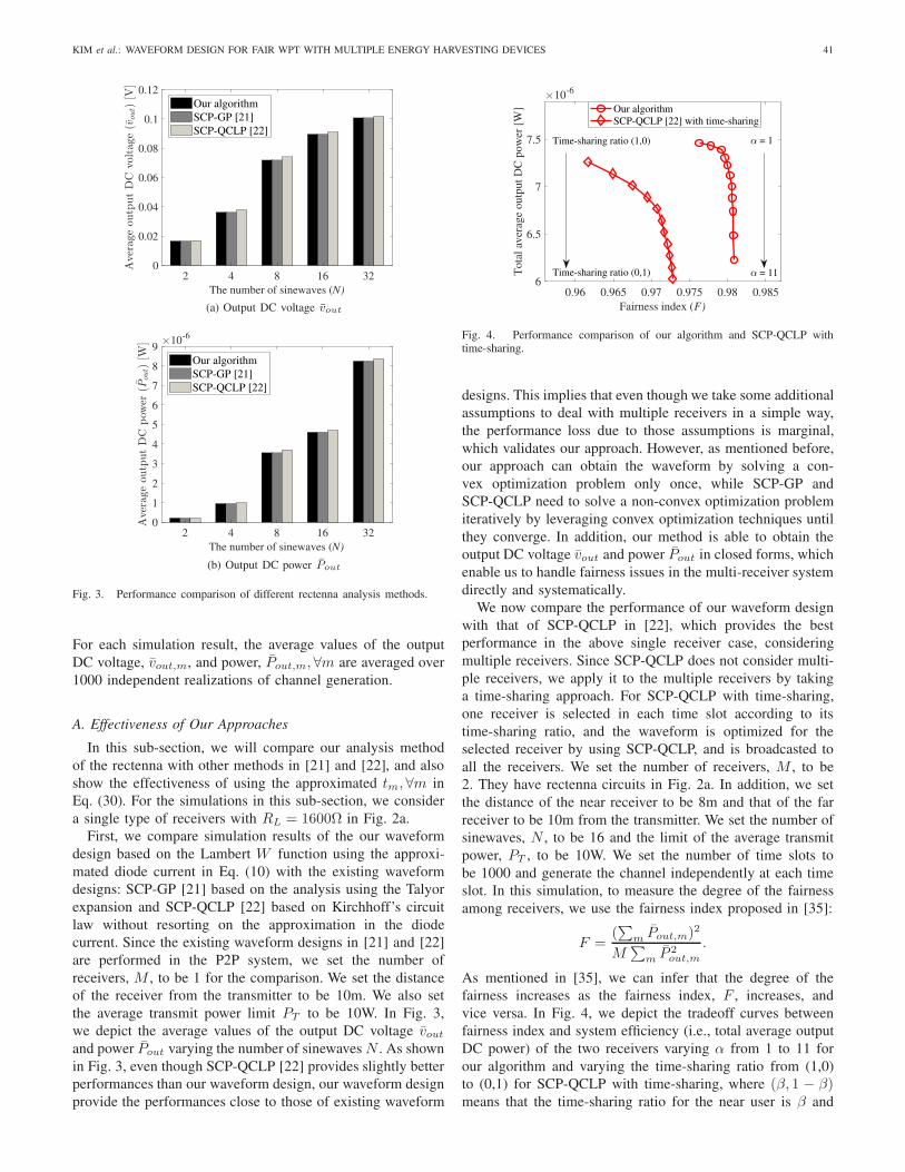
Fig. 3. Performance comparison of different rectenna analysis methods.
For each simulation result, the average values of the outputDC voltage, vout,m, and power, Pout,m, ∀m are averaged over1000 independent realizations of channel generation.
A. Effectiveness of Our Approaches
In this sub-section, we will compare our analysis methodof the rectenna with other methods in [21] and [22], and alsoshow the effectiveness of using the approximated tm, ∀m inEq. (30). For the simulations in this sub-section, we considera single type of receivers with RL = 1600Ω in Fig. 2a.
First, we compare simulation results of the our waveformdesign based on the Lambert W function using the approxi-mated diode current in Eq. (10) with the existing waveformdesigns: SCP-GP [21] based on the analysis using the Talyorexpansion and SCP-QCLP [22] based on Kirchhoff’s circuitlaw without resorting on the approximation in the diodecurrent. Since the existing waveform designs in [21] and [22]are performed in the P2P system, we set the number ofreceivers, M , to be 1 for the comparison. We set the distanceof the receiver from the transmitter to be 10m. We also setthe average transmit power limit PT to be 10W. In Fig. 3,we depict the average values of the output DC voltage voutand power Pout varying the number of sinewaves N . As shownin Fig. 3, even though SCP-QCLP [22] provides slightly betterperformances than our waveform design, our waveform designprovide the performances close to those of existing waveform
Fig. 4. Performance comparison of our algorithm and SCP-QCLP withtime-sharing.
designs. This implies that even though we take some additionalassumptions to deal with multiple receivers in a simple way,the performance loss due to those assumptions is marginal,which validates our approach. However, as mentioned before,our approach can obtain the waveform by solving a con-vex optimization problem only once, while SCP-GP andSCP-QCLP need to solve a non-convex optimization problemiteratively by leveraging convex optimization techniques untilthey converge. In addition, our method is able to obtain theoutput DC voltage vout and power Pout in closed forms, whichenable us to handle fairness issues in the multi-receiver systemdirectly and systematically.
We now compare the performance of our waveform designwith that of SCP-QCLP in [22], which provides the bestperformance in the above single receiver case, consideringmultiple receivers. Since SCP-QCLP does not consider multi-ple receivers, we apply it to the multiple receivers by takinga time-sharing approach. For SCP-QCLP with time-sharing,one receiver is selected in each time slot according to itstime-sharing ratio, and the waveform is optimized for theselected receiver by using SCP-QCLP, and is broadcasted toall the receivers. We set the number of receivers, M , to be2. They have rectenna circuits in Fig. 2a. In addition, we setthe distance of the near receiver to be 8m and that of the farreceiver to be 10m from the transmitter. We set the number ofsinewaves, N , to be 16 and the limit of the average transmitpower, PT , to be 10W. We set the number of time slots tobe 1000 and generate the channel independently at each timeslot. In this simulation, to measure the degree of the fairnessamong receivers, we use the fairness index proposed in [35]:
F =(∑
m Pout,m)2
M∑m P
2out,m
.
As mentioned in [35], we can infer that the degree of thefairness increases as the fairness index, F , increases, andvice versa. In Fig. 4, we depict the tradeoff curves betweenfairness index and system efficiency (i.e., total average outputDC power) of the two receivers varying α from 1 to 11 forour algorithm and varying the time-sharing ratio from (1,0)to (0,1) for SCP-QCLP with time-sharing, where (β, 1 − β)means that the time-sharing ratio for the near user is β and

42 IEEE JOURNAL ON SELECTED AREAS IN COMMUNICATIONS, VOL. 37, NO. 1, JANUARY 2019
Fig. 5. Comparison of the average output DC power with differentapproximated tm’s.
that for the far user is 1 − β. As shown in Fig. 4, as αincreases in our algorithm and the time-sharing ratio of the farreceiver increases in SCP-QCLP with time-sharing, the degreeof the fairness increases, while the system efficiency decreases.However, our algorithm achieves the higher degree of thefairness and system efficiency than SCP-QCLP with time-sharing. This implies that in the multi-receiver system, it isimportant to design the waveform with jointly consideringmultiple receivers, as in our algorithm, to improve the fairnessand system efficiency.
Lastly, to show the effectiveness of using the approximatedvalues of tm, ∀m in Eq. (30), we compare the averagePout,m, ∀m of our waveform designs with tm, ∀m in Eq. (30)and with tm = 0, ∀m. We set α to be 1 and the averagetransmit power limit, PT , to be 10W. We set the number ofreceivers to be 8 and the distances of receivers to be evenlyspaced in [8,15]m. In Fig. 5, we compare the achieved averagePout of each of the receivers for two different numbers ofsinwaves, i.e., N = 16 and N = 32.
As shown in this figure, by using tm, ∀m in Eq. (30), we canimprove the average output power Pout of all the receiverssignificantly compared with the naive approach with tm =0, ∀m. This implies that even though our approximated tm, ∀min Eq. (30) may not be optimal, it is simple and quite effectiveto improve the performance of the waveform design.
Fig. 6. Average output DC power with M = 2.
B. Performance of Our Waveform Design
In this sub-section, we provide the properties and perfor-mance of our waveform design.
First, to show the properties of our fair waveform designclearly, we set the number of receiver, M , to be 2. We setthe number of the sinewaves, N , to be 32 and the limit of theaverage transmit power, PT to be 10W.
In Fig. 6, we compare the average Pout’s of the tworeceivers varying α in the utility function from 1 to 10 for twocases: a case when the receivers have the same load resistancebut different locations and a case when the receivers havedifferent load resistances but the same location. In Fig. 6a,two receivers with the same load resistance, R = 1600Ω, arelocated at 8m and 10m from the transmitter. We denote the 8mreceiver as receiver 1, and the 10m receiver as receiver 2. Sincereceiver 1 is closer to the transmitter than receiver 2, the formerobtains a higher average DC power than the latter. However,as α increases, the difference between them decreases. Thisimplies that as α increases, the degree of fairness increases,as expected. In Fig. 6b, two receivers with different loadresistances R = 1600Ω and R = 2000Ω, denoted as receiver 1and receiver 2, respectively, are located at 10m from thetransmitter. Since we assume that perfect impedance matching,the output DC voltage is the same for the same receivedsignals. Accordingly, as shown in this figure, receiver 1 canobtain a higher output DC power than receiver 2 with the

KIM et al.: WAVEFORM DESIGN FOR FAIR WPT WITH MULTIPLE ENERGY HARVESTING DEVICES 43
Fig. 7. Channel response of each receiver when M = 2 and N = 32.
same received signals. However, as in the previous case, as αincreases, the difference between them decreases, and thus,the degree of fairness increases.
To explain how our waveform design achieves the fairness,as in Fig. 6, we depict a particular channel frequency responsesof the receivers in Fig. 7 for the two cases in Fig. 6, andunder those channel frequency responses, we also depict theamplitudes of sinewaves in our waveform design when α = 1and α = 10 in Fig. 8. From Figs. 7 and 8, we can observethat the sinewaves with higher channel responses are assignedhigher amplitudes in general for efficient WPT. However,in both cases, when α is small (i.e., α = 1), the shapeof the amplitudes of sinewaves is more aligned with theshape of the channel frequency responses of the receiverswith better energy harvesting conditions, i.e., receivers at asmaller distance and with a smaller load resistance, whilewhen α is large (i.e., α = 10), it is more aligned withthat of receivers with worse energy harvesting conditions, i.e.receivers at a larger distance and with a larger load resistance.This implies that with larger α, the shape of the waveformbecomes more favorable to the receivers with worse energyharvesting conditions than the receivers with better energyharvesting conditions to achieve a higher degree of energyharvesting fairness, as desired.
Second, we set the number of receivers, M , to be 10, andset the locations of receivers to be evenly spaced in the rangeof [8, 17]m from the transmitter. We also set the limit of theaverage transmit power, PT , to be 10W. In Fig. 9, we depictthe tradeoff between fairness index and total average output
Fig. 8. Amplitude of each sinewave with channel frequency response in Fig. 7for α = 1 and α = 10.
DC power varying α with different numbers of sinewaves fortwo cases: a case where the receivers have the same loadresistor with RL = 1600Ω and a case where the receivers inthe range of [8, 12] have the load resistor with RL = 1600Ωand the others have the load resistor with RL = 2000Ω. Asshown in Fig. 9, as α becomes large, the degree of the fairness(i.e., the fairness index) increases, while the system efficiency(i.e., the total average output DC power) decreases, as weexpected. This implies that we can control the tradeoff betweendegree of the fairness and system efficiency by appropriatelycontrolling α. In addition, with a larger number of sinewaves,we can achieve higher degree of the fairness and higher systemefficiency. This implies that a large number of sinewaves isbeneficial to improving both fairness and system efficiency.This figure also shows that we can achieve a higher degreeof fairness for the homogeneous receivers (with the sameresistance) than the heterogeneous receivers (with the differentresistances).
C. Comparison of Fairness Performance Between PowerBased Waveform and Voltage Based Waveform
In this sub-section, we compare the performance of ourwaveform design obtained by applying the output DC powerdirectly, called the power based waveform, and the perfor-mance of the waveform applying the output DC voltage, calledthe voltage based waveform.
Since our approach can derive the output DC power in aclosed form, we can use it in our optimization problem so asto achieve fair output DC powers directly.
However, in [24], the problem for waveform design isformulated so as to achieve fair output DC voltages instead offair output DC powers. Since the output DC power increases asthe output DC voltage increases, we can achieve the fairness interms of output DC powers indirectly to some degree through

44 IEEE JOURNAL ON SELECTED AREAS IN COMMUNICATIONS, VOL. 37, NO. 1, JANUARY 2019
Fig. 9. Tradeoff between fairness index and total average output DC power.
the fairness in terms of output DC voltages. However, sincethey do not have a linear relationship, i.e., the power linearlyincreases with the square of the voltage, if possible, it is betterto deal with the fairness in terms of the output DC powerdirectly. To obtain the voltage based waveform, we use thesame approach to our approach except that we replace theoutput DC power, Pout,m, in the utility function in Eq. (23)with the output DC voltage, vout,m.
We first consider two receivers whose load resistances aredifferent. One has the rectenna circuit with RL = 1600Ω forthe load resistance, and the other has the rectenna circuit withRL = 2000Ω for the load resistance. We set the distance ofthe receiver with RL = 1600Ω to be 8m, and that of thereceiver with RL = 2000Ω to be 10m, and then, we denotethem as receiver 1 and receiver 2, respectively. We also set thenumber of sinewaves, N , to be 32, and the limit of the averagetransmit power, PT , to be 10W. In Fig. 10, we depict theaverage Pout’s of each receiver varying α from 1 to 10. We canobserve that the power based waveform design achieve a muchhigher degree of fairness than the voltage based waveformdesign as α increases. This implies that the power basedwaveform provides a higher performances than the voltagebased waveform.
We now set the number of receivers, M , to be 10, and theirlocations to be evenly spaced in the range of [8, 17]m from thetransmitter. We set the load resistance of the receivers locatedin [8, 12]m to be 1600Ω, and that of the receivers located in[13, 17]m to be 2000Ω. We also set the limit of the averagetransmit power, PT , to be 10W. In Fig. 11, to show the tradeoff
Fig. 10. Comparison of the average DC powers of power based waveformand voltage based waveform with M = 2.
Fig. 11. Performance comparison of power based waveform and voltagebased waveform.
between fairness index and total average output DC power,we depict the fairness index versus the total average outputDC power varying α from 1 to 10, with different numbers ofsinewaves N . We can observe that as α increases, the degreeof the fairness (i.e., fairness index) increases and the systemefficiency (i.e., total average output DC power) decreasesin both waveform designs. In addition, this figure clearlyshows that the power based waveform design achieves bothhigher degree of fairness and higher system efficiency than thevoltage based waveform design. This implies that the powerbased waveform design gives higher performance in terms of

KIM et al.: WAVEFORM DESIGN FOR FAIR WPT WITH MULTIPLE ENERGY HARVESTING DEVICES 45
both fairness and system efficiency than the voltage basedwaveform design in the multi-receiver system. Even thoughthe approach that optimizes the output DC power consideringthe output DC voltage indirectly can be a good approach inthe single receiver WPT system since the output DC poweris an increasing function of the output DC voltage, it canbe inefficient in the multi-receiver system, since the outputDC power is a non-linear function of the output DC voltage.Hence, the approach that optimizes the output DC powerdirectly, as in our approach, is beneficial to improving theperformance of the multi-receiver WPT system.
V. CONCLUSION AND FUTURE WORKS
This paper studied the waveform design for fair WPT in themulti-receiver WPT system. To analyze the rectenna circuit,we used a different approach with the Lambert W functionfrom the previous approaches [21], [22]. Our approach enablesus to derive the output DC voltage and power of the rectifier inclosed forms, while providing similar performance with thosein [21] and [22]. With the closed forms of output DC voltageand power, we could deal with the fairness issues in WPT ina systematic way through α-proportional fairness concept andrigorous optimization framework, and design a fair waveformwith an algorithm with low complexity. The results showthat our waveform design can easily control the degree ofthe fairness for energy harvesting among receivers, and thus,effectively mitigate the near-far problem in the multi-receiverWPT system.
Our analysis and approach in this paper can be extended inseveral directions. First, we considered a single diode rectifiercircuit. However, it has been known that we can improve WPTperformance with the multi-diode rectifier circuits, and thus,the waveform design for the multi-diode rectifier circuits isan interesting and important future work to study. Second,we studied the waveform design assuming that the diode inthe rectifier is not saturated. However, it is also an interestingand important future work to study the saturation effects ofthe diode in waveform design. Even though it may not bestraightforward to extend our analysis and approach to studythe multi-diode rectifier circuits and the saturation effects ofthe diode, we think that our work in this paper would be usefulto study them.
APPENDIX APROOF OF PROPOSITION 1
Since the objective function of the problem (P1) is a non-negative weighted sum of utilities of receivers, Gα,m(sr, si)’s,it is sufficient to prove that Gα,m(sr, si) is a concave functionwhen α ≥ 1.
When α = 1, using the basic property of the Lambert Wfunction in Eq. (20), G1,m(sr, si) is obtained as
G1,m(sr, si) = log
([c1W0
(gm(sr, si)
)]2
RL,m
)
= c+√
2c23(N∑
n=1
srnhrn,m − sinh
in,m)
− 2 W0
(gm(sr, si)
), (34)
where c = log(c21 c
22,m/RL,m
). Then, using Eq. (21),
the Hessian matrix, H1, of G1,m(sr, si) is obtained as
H1 = −4c23W0
(gm(sr, si)
)
(1 +W0 (gm(sr, si))))3· hhT , (35)
where h = (hr1,m, . . . , hrN,m,−hi1,m, . . . ,−hiN,m)T . Since
gm(sr, si) is always non-negative, the multiplied term withhhT is always negative for any (sr, si). In addition, hhT ispositive definite [36]. Accordingly, H1 is a negative semi-definite matrix. Hence, Gα,m(sr, si) is a concave functionwhen α = 1.
When α > 1, Gα,m(sr, si) is represented as
Gα,m(sr, si) =1
1 − α
([c1W0
(gm(sr, si)
)]2
RL,m
)1−α
. (36)
Then, by using Eq. (21), the Hessian matrix, Hα, is obtainedas
Hα = 4c23[(1 − 2α)
(1 +W0
(gm(sr, si)
))+ 1
]
×(W0
(gm(sr, si)
))2−2α
(1 +W0 (gm(sr, si)))3hhT , (37)
and the multiplied term with hhT is negative for any (sr, si)when α > 1, and hhT is positive definite [36]. Accordingly,when α > 1, Hα is a negative semi-definite matrix. Hence,Gα,m(sr, si) is a concave function when α > 1.
Thus, the objective function in the problem (P1) is a concavefunction when α ≥ 1.
APPENDIX BDERIVATION OF EQ. (33)
Since the problem (P1) is a convex optimization problem,we can obtain the optimal solution by using the KKT condi-tions. To derive Eq. (33), let us define the Lagrange functionof the problem (P1) as follows:
L(sr, si, λ) =2∑
m=1
Gα,m(sr, si)
−λ
(N∑
n=1
((srn)2 + (srn)
2) − PT
), (38)
where λ is a non-negative Lagrange multiplier associatedwith the average transmit power constraint. By differentiatingEq. (38) with respect to srk and sik, ∀k, and applying the KKTstationarity conditions, we obtain the following equations.
∂L(sr, si, λ)∂srk
= 0
⇔ a2−2α1
√2c23h
rk,1
1 + a1+ a2−2α
2
√2c23h
rk,2
1 + a2=
2λsrkc1
, ∀k,(39)
∂L(sr, si, λ)∂sik
= 0
⇔ −a2−2α1
√2c23h
ik,1
1 + a1− a2−2α
2
√2c23h
ik,2
1 + a2=
2λsrkc1
, ∀k,(40)

46 IEEE JOURNAL ON SELECTED AREAS IN COMMUNICATIONS, VOL. 37, NO. 1, JANUARY 2019
with c1 = (c1/RL)1−α and am =W0
(c2 exp
(√2c23
∑Nj=1 s
rjhrj,m − sijh
ij,m
)), ∀m, where
c2 = RLIS/ηV0 and c3 =√Rant/ηV0 in Eq. (19). Since the
left hand sides of Eqs. (39) and (40) is not zero, in orderto satisfy the stationarity condition, we have λ > 0. Then,to satisfy the KKT slackness condition, the constraint mustbe tightly satisfied as
∑
n
(srn)2 + (sin)2 = PT . (41)
Accordingly, with the assumption that perfect tm, ∀m and aftersome manipulations based on Eqs. (3), (39), (40) and (41),we can obtain Eq. (33).
REFERENCES
[1] C. R. Valenta and G. D. Durgin, “Harvesting wireless power: Surveyof energy-harvester conversion efficiency in far-field, wireless powertransfer systems,” IEEE Microw. Mag., vol. 15, no. 4, pp. 108–120,Jun. 2014.
[2] X. Lu, P. Wang, D. Niyato, D. I. Kim, and Z. Han, “Wireless networkswith RF energy harvesting: A contemporary survey,” IEEE Commun.Surveys Tuts., vol. 17, no. 2, pp. 757–789, 2nd Quart., 2015.
[3] X. Lu, P. Wang, D. Niyato, D. I. Kim, and Z. Han, “Wireless chargingtechnologies: Fundamentals, standards, and network applications,” IEEECommun. Surveys Tuts., vol. 18, no. 2, pp. 1413–1452, 2nd Quart., 2016.
[4] Y. Zeng, B. Clerckx, and R. Zhang, “Communications and signals designfor wireless power transmission,” IEEE Trans. Commun., vol. 65, no. 5,pp. 2264–2290, May 2017.
[5] J. P. Thomas, M. A. Qidwai, and J. C. Kellogg, “Energy scavengingfor small-scale unmanned systems,” J. Power Sources, vol. 159, no. 2,pp. 1494–1509, Sep. 2006.
[6] X. Shao, B. Li, N. Shahshahan, N. Goldsman, T. S. Salter, andG. M. Metze, “A planar dual-band antenna design for RF energyharvesting applications,” in Proc. IEEE ISDRS, Dec. 2011, pp. 1–2.
[7] J. M. Barcak and H. P. Partal, “Efficient RF energy harvesting by usingmultiband microstrip antenna arrays with multistage rectifiers,” in Proc.IEEE SubVT, Oct. 2012, pp. 1–3.
[8] M. T. Penella-López and M. Gasulla-Forner, “Radiofrequency energyharvesting,” in Powering Autonomous Sensors. New York, NY, USA:Springer-Verlag, 2011, pp. 125–147.
[9] S. Agrawal, S. Pandey, J. Singh, and P. N. Kondekar, “An efficient RFenergy harvester with tuned matching circuit,” in Proc. VLSI DesignTest, Commun. Comput. Inf. Sci, vol. 382, 2013, pp. 138–145.
[10] J. A. Hagerty, F. B. Helmbrecht, W. H. McCalpin, R. Zane, andZ. B. Popovic, “Recycling ambient microwave energy with broad-bandrectenna arrays,” IEEE Trans. Microw. Theory Techn., vol. 52, no. 3,pp. 1014–1024, Mar. 2004.
[11] J.-P. Curty, N. Joehl, F. Krummenacher, C. Dehollain, andM. J. Declercq, “A model for μ-power rectifier analysis and design,”IEEE Trans. Circuits Syst. I, Reg. Papers, vol. 52, no. 12, pp. 2771–2779,Dec. 2005.
[12] H. J. Visser and R. J. M. Vullers, “RF energy harvesting and transportfor wireless sensor network applications: Principles and requirements,”Proc. IEEE, vol. 101, no. 6, pp. 1410–1423, Jun. 2013.
[13] D. I. Kim, J. H. Moon, and J. J. Park, “New SWIPT using PAPR: Howit works,” IEEE Wireless Commun. Lett., vol. 5, no. 6, pp. 672–675,Dec. 2016.
[14] B. Clerckx, “Wireless information and power transfer: Nonlinear-ity, waveform design, and rate-energy tradeoff,” IEEE Trans. SignalProcess., vol. 66, no. 4, pp. 847–862, Feb. 2018.
[15] J.-M. Kang, I.-M. Kim, and D. I. Kim, “Wireless information and powertransfer: Rate-energy tradeoff for nonlinear energy harvesting,” IEEETrans. Wireless Commun., vol. 17, no. 3, pp. 1966–1981, Mar. 2018.
[16] E. Boshkovska, D. W. K. Ng, N. Zlatanov, and R. Schober, “Prac-tical non-linear energy harvesting model and resource allocation forSWIPT systems,” IEEE Commun. Lett., vol. 19, no. 12, pp. 2082–2085,Dec. 2015.
[17] A. Boaventura, A. Collado, N. B. Carvalho, and A. Georgiadis, “Opti-mum behavior: Wireless power transmission system design throughbehavioral models and efficient synthesis techniques,” IEEE Microw.Mag., vol. 4, no. 2, pp. 26–35, Mar./Apr. 2013.
[18] A. S. Boaventura and N. B. Carvalho, “Maximizing DC power inenergy harvesting circuits using multisine excitation,” in IEEE MTT-SInt. Microw. Symp. Dig., Jun. 2011, pp. 1–4.
[19] A. Collado and A. Georgiadis, “Optimal waveforms for efficient wirelesspower transmission,” IEEE Microw. Wireless Compon. Lett., vol. 24,no. 5, pp. 354–356, May 2014.
[20] A. Boaventura, D. Belo, R. Fernandes, A. Collado, A. Georgiadis, andN. B. Carvalho, “Boosting the efficiency: Unconventional waveformdesign for efficient wireless power transfer,” IEEE Microw. Mag., vol. 16,no. 3, pp. 87–96, Apr. 2015.
[21] B. Clerckx and E. Bayguzina, “Waveform design for wireless powertransfer,” IEEE Trans. Signal Process., vol. 64, no. 23, pp. 6313–6328,Dec. 2016.
[22] M. R. V. Moghadam, Y. Zeng, and R. Zhang, “Waveform optimizationfor radio-frequency wireless power transfer: (Invited paper),” in Proc.IEEE Workshop SPAWC, Jul. 2017, pp. 1–6.
[23] B. Clerckx and E. Bayguzina, “Low-complexity adaptive multisinewaveform design for wireless power transfer,” IEEE Antennas WirelessPropag. Lett., vol. 16, pp. 2207–2210, 2017.
[24] Y. Huang and B. Clerckx, “Large-scale multiantenna multisine wire-less power transfer,” IEEE Trans. Signal Process., vol. 65, no. 21,pp. 5812–5827, Nov. 2017.
[25] H. Ju and R. Zhang, “Throughput maximization in wireless poweredcommunication networks,” IEEE Trans. Wireless Commun., vol. 13,no. 1, pp. 418–428, Jan. 2014.
[26] R. M. Corless, G. H. Gonnet, D. E. G. Hare, D. J. Jeffrey, andD. E. Knuth, “On the Lambert W function,” Adv. Comput. Math., vol. 5,no. 4, pp. 329–359, Jun. 1996.
[27] J. Mo and J. Walrand, “Fair end-to-end window-based congestioncontrol,” IEEE/ACM Trans. Netw., vol. 8, no. 5, pp. 556–567, Oct. 2000.
[28] Y. Zeng and R. Zhang, “Optimized training design for wirelessenergy transfer,” IEEE Trans. Commun., vol. 63, no. 2, pp. 536–550,Feb. 2015.
[29] K. Choi, D. Kim, and M. Y. Chung, “Received power-based channelestimation for energy beamforming in multiple-antenna RF energytransfer system,” IEEE Trans. Signal Process., vol. 65, no. 6,pp. 1461–1476, Mar. 2017.
[30] J. Xu and R. Zhang, “A general design framework for MIMO wirelessenergy transfer with limited feedback,” IEEE Trans. Signal Process.,vol. 64, no. 10, pp. 2475–2488, May 2016.
[31] B. Razavi, Fundamentals of Microelectronics. New York, NY, USA:Wiley, 2008.
[32] Z. L. Krougly and D. J. Jeffrey, “Implementation and applicationof extended precision in MATLAB,” in Proc. ACC, WSEAS Press,Sep. 2009, pp. 28–30.
[33] M. Grant and S. Boyd. CVX: MATLAB Software for Disciplined ConvexProgramming, Version 2.1. Accessed: Oct. 2017. [Online]. Available:http://cvxr.com/cvx
[34] S. Boyd and L. Vandenberghe, Convex Optimization. Cambridge, U.K.:Cambridge Univ. Press, 2004.
[35] R. K. Jain, D. M. W. Chiu, and W. R. Hawe, “A quantitative measure offairness and discrimination for resource allocation in shared systems,”Digit. Equip. Corp., Maynard, MA, USA, Tech. Rep. TR-301, Sep. 1984.
[36] G. Strang, Linear Algebra and Its Applications. London, U.K.: CengageLearning, 2006.
Kyeong-Won Kim received the B.S. degree inelectrical and electronic engineering from YonseiUniversity, Seoul, South Korea, in 2016, where heis currently pursuing the Ph.D. degree with theSchool of Electrical and Electronic Engineering.His research interests include the areas of resourceallocation in wireless networks and optimizationproblems in communication networks and wirelesspower transfer.

KIM et al.: WAVEFORM DESIGN FOR FAIR WPT WITH MULTIPLE ENERGY HARVESTING DEVICES 47
Hyun-Suk Lee received the B.S. and Ph.D. degreesin electrical and electronic engineering from YonseiUniversity, Seoul, South Korea, in 2012 and 2018,respectively. Since 2018, he has been a Post-Doctoral Research Associate with the Institute ofBioMed-IT, Energy-IT and Smart-IT Technology,a Brain Korea 21 Plus Program, Yonsei University.His research interests include communication net-works, wireless power transfer, and smart grid.
Jang-Won Lee (M’04–SM’12) received theB.S. degree in electronic engineering from YonseiUniversity, Seoul, South Korea, in 1994, the M.S.degree in electrical engineering from the KoreaAdvanced Institute of Science and Technology,Daejeon, South Korea, in 1996, and the Ph.D.degree in electrical and computer engineeringfrom Purdue University, West Lafayette, IN, USA,in 2004. From 1997 to 1998, he was with theDacom R&D Center, Daejeon. From 2004 to 2005,he was a Post-Doctoral Research Associate with
the Department of Electrical Engineering, Princeton University, Princeton,NJ, USA. Since 2005, he has been with the School of Electrical andElectronic Engineering, Yonsei University, where he is currently a Professor.His research interests include resource allocation, QoS and pricing issues,optimization, and performance analysis in communication networks, andsmart grid.


