Embed Size (px)
Citation preview

Wave Impact, Body Motion and
Overset Grids in STAR-CCM+
Milovan Perić

Features of STAR-CCM+ enabling studies of wave
impact and motion of floating bodies
Overset grids in STAR-CCM+
Fluid-structure interaction
Examples of application
Future developments
Introduction

Features of STAR-CCM+ enabling studies of wave
impact and flow-induced floating body motion:
– High-resolution interface-capturing scheme
– Wave generation models
– Wave damping
– Second-order time advancing
– Dynamic fluid-body interaction (DFBI) with 6 degrees of
freedom
– Mesh motion and adaptation techniques:
• Mesh morphing
• Sliding grids
• Overset grids
Enabling Technology

HRIC-scheme was developed in late 1990es and resolves a sharp interface by one cell…
FLUENT also adopted it (but it is not identical to STAR-CCM+ implementation – less sharp interface)…
Control parameters:
– Courant number limits:
• Below lower limit, pure HRIC is used to transport volume fraction;
• Above upper limit, pure 1st-order upwind scheme is used;
• Between the limit the two schemes are blended.
– Sharpening factor:
• Based on an anti-diffusion model developed by H. Weller
• Used to avoid irreversible mixing due to occasional use of upwind scheme (splashing, wave breaking etc.)
High-Resolution Interface-Capturing, I
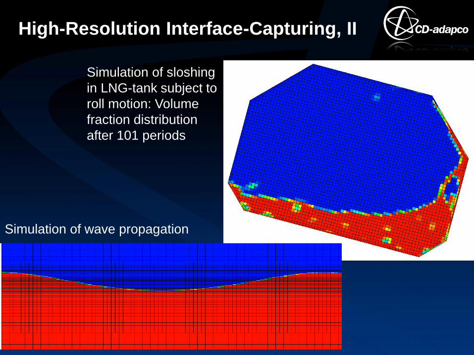
High-Resolution Interface-Capturing, II
Simulation of sloshing
in LNG-tank subject to
roll motion: Volume
fraction distribution
after 101 periods
Simulation of wave propagation
STAR-CCM+ provides several wave models:
– For initialization of volume fraction, velocity and pressure
fields;
– For a transient inlet boundary condition.
Currently available models:
– 1st-order linear wave theory
– Non-linear 5th-order Stokes wave theory (Fenton, 1985)
– Pierson-Moskowitz and JONSWAP long-crested wave
spectra
– Superposition of linear waves with varying amplitude,
period and direction of propagation (can be set-up via
Excel-file)
Wave Models
w w
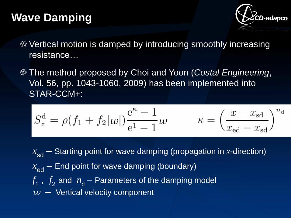
Vertical motion is damped by introducing smoothly increasing
resistance…
The method proposed by Choi and Yoon (Costal Engineering,
Vol. 56, pp. 1043-1060, 2009) has been implemented into
STAR-CCM+:
Wave Damping
xsd
– Starting point for wave damping (propagation in x-direction)
xed
– End point for wave damping (boundary)
f1 , f
2 and n
d – Parameters of the damping model
w – Vertical velocity component

Accurate wave propagation requires 2nd-order time-integration method.
Second-order method (quadratic interpolation in time) requires that the wave propagates less than half a cell per time step.
First-order scheme is always stable but less accurate…
Test case:
– Stokes 5th-order wave
– Wavelength 102.7 m
– Wave height 5.8 m
– Wave period 8 s
– Solution domain 4 wavelengths long…
Time-Accurate Wave Propagation, I

Time-Accurate Wave Propagation, II
Wave damping was applied over the last 100 m before outlet... 41 cells
per wave length, 11.5 cells per wave height (Δx = 2.5 m, Δz = 0.5 m)
1st-order scheme, 100 Δt/T (Co = 0.41), after 4 periods
2nd-order scheme, 100 Δt/T (Co = 0.41), after 4 periods
5 cells
10 cells

Time-Accurate Wave Propagation, III
Wave train initialized using Stokes 5th-order theory
Solution domain 1002 m long (8 wavelengths)
Damping applied over last 300 m
Wave period 8.977 s, wave height 5 m
20 cells per wave height, 80 cells per wavelength
Second-order time integration scheme (quadratic backward)
Initial wave profile:
Damping applied
to initial field...

Time-Accurate Wave Propagation, IV
Wave profile after 100 s of simulation time (> 11 periods).
Note: 1 cell resolution, almost no reduction in amplitude…
Essential for accurate prediction of wave propagation:
- 2nd-order discretization in time
- Order of 20 cells per wave height and 80 cells per wavelength
DFBI model computes motion of a rigid body (up to six
degrees of freedom).
Second-order discretization in space and time is used
(compatible to discretization in flow domain).
Body motion is affected by:
– Flow-induced forces and moments (from shear and
pressure forces);
– Gravity;
– Specified external forces and moments;
– Couplings (springs, catenaries,…).
Dynamic Fluid-Body Interaction, I

Dynamic Fluid-Body Interaction, II
Coupled simulation of flow
and flow-induced motion of
floating bodies:
Implicit coupling by
updates within outer
iteration loop…
Applies also to deformable
structures (needs compu-
tation of body deformation).

Grid can be adapted to a moving body by several methods:
– Morphing,
– Embedded rigid body motion (a combination of rotation with a
sliding interface and translation),
– Overset grids.
Grid Adaptation in Fluid
An example of grid
adaptation using morphing
for a prescribed
deformation of a body.

Multiple regions (background, overset)…
Each region is associated with one grid continuum (any
grid type).
Overset grid interface needs to be set for regions,
overset boundary on overset grids…
Cells are automatically grouped into active and passive.
Active cells along interface to passive cells refer to donor
cells at another grid instead of the passive neighbours on
the same grid...
The first layer of passive cells next to active cells are
called acceptor cells...
Overset Grids, I

Variable values at acceptor cells are expressed via
variable values at donor cells using an interpolation
function.
Overset Grids, II
Background
grid
Overset
grid
N1, N2, N3 –
Neighbors from
the same grid;
N4, N5, N6 –
Neighbors from
the overlapping
grid.

In the overlapping zone, cells should be of comparable
size (recommendation).
Between two walls belonging to different grids, there
should be at least 4 cells to enable coupling
(requirement).
The overset grid should not move more than one cell per
time step (recommendation).
Overset Grids, III
Pitching foil in a
channel
Store separation

Coupled computation of flow and flow-induced
deformation of structure: implicit coupling is essential…
Having both solvers in a single code (even if different
methods, like FV and FE) is a big advantage –
communication via memory…
A finite-element solver for structures (3D, beams, plates,
shells, membranes) is being developed in STAR-CCM+…
Implicit coupling to ABAQUS is available since V 7.04 – a
great increase in robustness compared to explicit
coupling (exchange once per time step).
Explicit coupling with other FE codes is also possible.
Solution mapping available for non-conformal grids…
Fluid-Structure Interaction

Stokes wave slamming against a jack-up platform in
North Sea (GL)
Shallow water wave slamming against an offshore
structure (DNV)
Simulation of hurricane damage to a platform in the Gulf
of Mexico (Chevron; FSI, coupling to ABAQUS)
Simulation of ship bow and stern slamming (whipping,
springing; GL)
Lifeboat launching into waves (DNV, FEDEM, UMOE,
NORSAFE, CFD-Marin…)
Other applications of overset grids
Examples of Application

Wave Impact on Jack-Up Platform
CD-adapco in collaboration with GL

Wave Impact on Offshore Structure
Simulations by DNV (published at
OMAE2012 Conference)

Hurricane Damage on Oil Platform
Coupled simulation of
flow using STAR-CCM+
and deformation of
platform structure using
ABAQUS.
Simulation by CD-adapco
Engineering Services for
Chevron. Published at
OMAE2012 Conference.
Evidence of damage on a
platform after it was hit by
a hurricane
Deformation in a
simulation: good
agreement with field
observation…

Ship Slamming in Waves
Container ship in waves
Comparison of predicted
and measured mean
pressure over limited
area at two bow locations
(analysis by GL).

Effects of Ship Deformation, I
Analysis of whipping phenomena at GL: Green water on deck after one slamming event (upper), and Comparison of measured and computed accele- rations in bow region for a rigid and an elastic ship structure (lower).
Analysis by GL

Effects of Ship Deformation, II
Analysis by GL
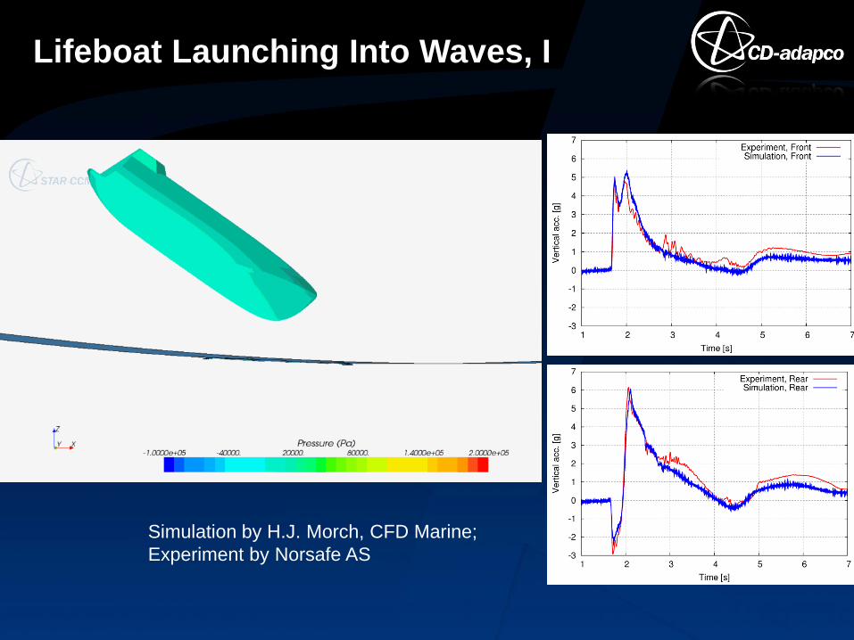
Lifeboat Launching Into Waves, I
Simulation by H.J. Morch, CFD Marine;
Experiment by Norsafe AS

Lifeboat Launching Into Waves, II
Initial wave position varied
by 20 m (drop from 32 m
height).
Following wave (180°)
Wavelength ca. 220 m,
wave height 13.5 m, water
depth 33.5 m
The questions to be
answered:
When is the load on the
structure the highest?
When are accelerations
the highest?

Lifeboat Launching Into Waves, III
Pressure at one monitoring point for
different hit points, 180°

Parametric Study With Overset Grids, I
Flow around a body at
different angles of attack
A horizontal section through
both grids (only active cells
are shown).
Total number of cells:
ca. 1 million
Vertical section through the
two grids (only active cells
are shown).

Parametric Study With Overset Grids, II
Velocity distribution in a section
parallel to bottom wall for different
angles of attack.
Steady-state solutions.
30°
-30° -15°
0° 15°

Parametric Study With Overset Grids, III
Residual history from the computation of flow around a body in a wind
tunnel at different angles of attack: time step 1000 s, rotation 15° per time
step, standard k-ε turbulence model, under-relaxation 0.9/0.1/0.9 for
velocities/pressure/turbulence, wind speed 40 m/s

Parametric Study With Overset Grids, IV
History of computed forces from the computation of flow around a body
in a wind tunnel at different angles of attack (since the time step is very
large, steady-state solutions are obtained for each body orientation).

Parametric Study With Overset Grids, V
Simulation of motion of a
container ship in Stokes
waves propagating from
right to left:
- Wave length equal to ship
length
- Initial vessel orientation 30°
(upper) and -30° (lower)
relative to the direction of
wave propagation

Parametric Study With Overset Grids, VI
Simulation of motion of a
container ship in Stokes
waves propagating from
right to left

Vessels With Crossing Paths

Lifeboat Launched From a Platform
Wave propagates from
left to right
Wave propagates from
right to left
Additional motion models (prescribed motion + additional
DOF)
Internal wave generation
Superposition of nonlinear (Stokes 5th-order) waves
Short-crested wave spectra
Automatic setup of standard towing tank tests (circle, zig-
zag, PMM-tests etc.)
Fluid-Structure Interaction (internal FE-models for
beams, plates, shells, membranes…)
… and other enhancements requested by clients
(keyword: IdeaStorm!)
Future Developments

Thank you for your attention!