Embed Size (px)
Citation preview

Global Space Exploration Conference. Washington D.C. United States. Copyright ©2012 by Marc M. Cohen; published under license by the International Astronautical Federation. All Rights Reserved.
GLEX-2012.10.1.9x12503
WATER WALLS ARCHITECTURE:
MASSIVELY REDUNDANT AND HIGHLY RELIABLE LIFE SUPPORT FOR LONG DURATION EXPLORATION MISSIONS
Marc M. Cohen, Arch.D
Marc M. Cohen Architect P.C. – Astrotecture™, Palo Alto, California USA
Michael T. Flynn, Principal Investigator, NASA Ames Research Center, Moffett Field, California USA
Renée L. Matossian, Architect, San Mateo, California, USA
The history of life support systems in space shows that mechanical life support systems have high duty cycles and consequent failure rates that make them problematic for long duration missions. Water Walls offers the potential for a largely passive system based on forward osmosis processes that will be much more reliable for long duration human exploration missions. Water Walls can also provide nutrient production and radiation shielding.
INTRODUCTION The lungs of our planet – the forests,
grasslands, marshes, and oceans – revitalize our atmosphere, clean our water, process our wastes, and grow our food by mechanically passive methods. Nature uses no compressors, evaporators, lithium hydroxide canisters, oxygen candles, or urine processors. For very long-term operation -- as in an interplanetary spacecraft, space station, or lunar/planetary base -- these active electro-mechanical systems tend to be failure-prone because the continuous duty cycles make maintenance difficult; redundant systems that would allow downtime are bulky, expensive, and heavy. They also multiply the same inefficiencies because they have the same failure-prone parts. In comparison, Nature’s passive systems operate using biological and chemical processes that do not depend upon machines and provide sufficient redundant cells, such that the failure of one or a few is not a problem.
Water Walls (WW) takes an analogous approach to providing a life support system that is biologically and chemically passive, using mechanical systems only for plumbing to pump fluids such as gray water from the source to the point of processing. The core processing technology of Water Walls is forward osmosis (FO). Each cell of the WW system consists of a polyethylene bag or tank with one or more FO membranes to provide the chemical processing of waste. WW provides four principal functions of
processing cells in five different types plus the common function of radiation shielding:
1. Gray water processing for urine and wash
water, 2. Black water processing for solid waste, 3. Air processing for CO2 removal and O2
revitalization, 4. Thermal and humidity control, 5. Food growth using green algae, 6. Provide radiation protection to the crew
habitat. Although chemically and biologically different,
these cells are physically similar in size and shape, so they can be physically integrated into the WW system. With this cellular and modular approach, the WW system is designed to be highly reliable by being massively redundant. As part of the spacecraft design, the replaceable cells and modules are installed in the structural matrix. Before interplanetary departure from a staging point in Low Earth Orbit (LEO) or from a Lagrange point, the cells are primed with water and starter ion solutions. As one cell for each function is used up, it is turned off; opening valves to admit the appropriate fluids turns on the next one.
The spacecraft carries backup FO bags and/or membranes. The crew can replace exhausted cells with new units. In this concept, WW can replace much of the conventional mechanically-driven life support that is so failure-prone with a reliable system that also affords “non-parasitic” radiation shielding and can grow

Global Space Exploration Conference. Washington D.C. United States. Copyright ©2012 by Marc M. Cohen, published by license by the International Astronautical Federation. All Rights Reserved.
GLEX-2012.10.1.9x12503
2
basic protein and carbohydrates to sustain the crew over multi-year missions.
Radiation Shielding constitutes a special feature of the Water Walls approach. Cohen (1997) presented an early water shielding approach to protect the crew habitat on an interplanetary vehicle (IPV) for a mission to Mars. This forerunner concept appears in FIGURE 1.
Its shortcoming was that the 42mton mass of water had only two functions, to provide shielding and a reserve of drinking water. This IPV shielding is shown at a cross-section thickness of 30cm of water (30g/cm areal density). Because of this limited functionality, the 1997 IPV shielding could be considered as “parasitic mass.”
FIGURE 1. Water-shielded crew habitat, 6m interior diameter for an interplanetary vehicle (Cohen, 1997).
THE CHALLENGE OF LONG DURATION LIFE SUPPORT
The romance of the machine hits its limits in designing, building, and operating mechanically- driven life support systems for long duration space missions. The repeated failures and crises on Mir and ISS demonstrate the difficulty of operating a mechanical life support system over a
period of years. It is not possible to launch all the necessary spare parts with the technicians and repair shop to keep these systems operating efficiently and reliably. Instead, NASA must look in another direction, a far simpler and more reliable system, that functions passively as the oceans and forests that are the air revitalization “lungs” of the planet Earth.

Global Space Exploration Conference. Washington D.C. United States. Copyright ©2012 by Marc M. Cohen, published by license by the International Astronautical Federation. All Rights Reserved.
GLEX-2012.10.1.9x12503
3
A New Approach Water Walls (WW) presents a new approach
to long duration life support. Instead of providing one or two heavy, excessively complex and, sensitive, expensive, and failure-prone pieces of mechanical equipment, the WW approach provides a large number of simple units based on forward osmosis (FO) to handle the same functions as conventional systems – and more. Instead of continuously active mechanical systems, WW is mostly passive, with only valves and small pumps as active elements – no compressors, evaporators, sublimators, distillers, adsorbers, or desorbers. Instead of the failure-prone mechanical Environmental Control and Life Support System (ECLSS) equipment that must operate continuously, WW modules are designed to have their capacity consumed gradually throughout the mission. As one unit is used up, the next in line takes over. In the case of the blackwater/solids cells, they leave a residue of dry biomass and CaCO3 that can continue to provide radiation shielding.
An interplanetary spacecraft would launch with its WW modules dry, then in Low Earth Orbit (LEO) or at an Earth-Moon Lagrange Point, they would be primed with water to “fuel” the life support. WW offers the promise of an inexpensive, modular, simple, low maintenance, highly reliable, and massively redundant system to outfit human interplanetary spacecraft, lunar, and Mars bases. Between interplanetary missions or for scheduled maintenance at a lunar/planetary base, crewmembers refurbish the Water Walls systems simply by replacing the disposable FO bags or membranes.
What is Forward Osmosis? Forward Osmosis (FO) is a natural process in
which the osmotic potential between two fluids of differing solute/solvent concentrations equalizes by the movement of solvent from the less concentrated solution to the more concentrated solution. Typically, this exchange occurs using a semi-permeable membrane that separates the two solutions, and allows the solvent to pass through the membrane pores but not the solute. This solvent flux continues until the osmotic potential across the membrane and solute/solvent concentrations equalizes. When an FO element exhausts its exchange potential, treatment ceases in that element; the WW system architecture then transfers the treatment function to the next bag or tank in that layer of the wall. Exhausted FO bag elements can be reused for another life support function: they are drained,
fluids are then mixed with feces, solid organic wastes, and advanced water treatment residuals are either re-injected for sludge treatment, or simply cured in place to a stable solid.
Description of the Concept Water Walls (WW) will provide the life
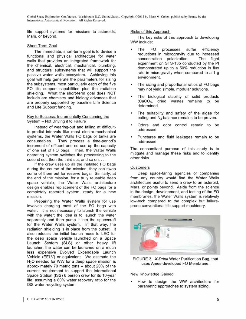
support functions of CO2 removal, O2 revitalization, urine and gray water recycling, and solid waste processing. The WW basic unit is a polyethylene bag or tank with one or more forward osmosis (FO) membranes in it, and valved orifices for input and output (Flynn, Delzeit, 2011). Currently, the WW water processing function for urine-to-water and gray water-to-potable water is fully mature, with such FO bags available commercially from Hydration Technologies, based on Ames life support technology (Gormly, Flynn, 2010).
FIGURE 2. FO Urine-to-Water Processing Bag
Tested on STS-135
WW achieved its first flight experiment milestone in flying a urine-to-water processing FO bag

Global Space Exploration Conference. Washington D.C. United States. Copyright ©2012 by Marc M. Cohen, published by license by the International Astronautical Federation. All Rights Reserved.
GLEX-2012.10.1.9x12503
4
experiment on STS-135, the last shuttle flight in 2011 (Hammoudeh, Flynn; 2012 in press). FIGURE 2 shows the flight test article prototype bag. That experiment accomplished the TRL-3 proof of concept for water reprocessing that FO membranes can perform urine-to-water processing in microgravity, (although the first test article showed an expected performance decrement compared to the ground-testing due to concentration polarization effects). The next sequence of research steps should include developing more sophisticated FO membranes and bags, detailed TRL-2 concept formulation, and laboratory tests plus microgravity flight tests to achieve TRL-3 proof of concept:1
• Solid waste (blackwater) processing and solidification for permanent storage of sterile waste as radiation shielding,
• Air processing for CO2 removal and O2 revitalization using a gas permeable air-to-water membrane,
• Growing algae for food from CO2 and processed solid waste, using a combination of the air processing external membrane and the solids processing internal membrane,
• Removing organic volatiles from the atmosphere through the air processing membrane and photo catalytic coatings on the interior walls of the space craft,
• Generating power for the sensors, pumps, and valves through a proton/ion exchange medium in a bag or tank installed within the WW physical and functional architecture.
• Demonstrate sensors embedded in each FO unit to signal the valves to open or close, and for the data system to command the mechanical system to pump fluids to their point of treatment or utilization.
• Demonstrate that the four layers of WW FO bags or tanks can double as a cost- and mass- effective radiation-shield.
1 Because Water Walls is such a passive, non-mechanical system, it needs flight-testing at TRL-3 to prove that each of the electro-chemical processes with each membrane type will work in microgravity. For example, to what extent does the air processing rely upon convection; do algae growth and processing of solid waste depend on gravity?
TECHNICAL DESCRIPTION The objective is to develop the Water Wall
system architecture for long duration life support. Water Walls is a breakthrough technology that is a gateway to performing long duration missions to building deep space reusable spacecraft.
Limitations of the Current Approaches Life support systems in human spacecraft
today are entirely electro-mechanical. They operate on high duty-cycle mechanical systems with little opportunity for maintenance, repair, or replacement. Therefore, they tend to be highly failure-prone as demonstrated time and again by the LS systems on Mir and ISS. Because Water Walls are passive like the natural systems on Earth, they are not vulnerable in the same way to single-point mechanical failure.
The Project The current project is to create the
preliminary design for a physical and functional architecture that accommodates an FO-based life support system. In this initial design cycle, the WW Architecture will provide this core, primary capabilities. Air revitalization provides CO2 removal and O2 replenishment. Gray water processing treats urine and wash water to produce potable water. Black water processing treats human solid waste to produce fertilizer and CaCO3 (gypsum that may be used as a building material). Algae growth sequesters CO2, affords tertiary solid waste processing, and produces nutritional supplement. The humidity and thermal control process also produces clean, potable water. The organic fuel proton exchange membrane cell offers a reversible process: to run “forward” to generate power or to run “backward” to sequester CO2. In addition, all the cells afford radiation shielding for the crew habitat. Because the WW cells that furnish radiation shielding also provide these many life support functions, the shielding is “non-parasitic,” that is not just there to provide passive mass for radiation protection.
Long-Term Goal The long-term goal of the WW Architecture is
to design, engineer, build, test, and operate a passive FO life support system that does not involve high duty-cycle, high wear mechanical systems but instead uses pumps and valves only intermittently to move fluids. This system can provide highly reliable, massively redundant life support for long duration (e.g. more than a year)
Global Space Exploration Conference. Washington D.C. United States. Copyright ©2012 by Marc M. Cohen, published by license by the International Astronautical Federation. All Rights Reserved.
GLEX-2012.10.1.9x12503
5
life support systems for missions to asteroids, Mars, or beyond.
Short-Term Goal The immediate, short-term goal is to devise a
functional and physical architecture for water walls that provides an integrated framework for the chemical, electrical, mechanical, plumbing, and structural subsystems that will support the passive water walls ecosystem. Achieving this goal will help generate the parameters for sizing the subsystems, most particularly each of the five FO life support capabilities plus the radiation shielding. What the short-term goal does NOT include are chemistry and biology advances that are properly supported by baseline Life Science and Life Support funding.
Key to Success: Incrementally Consuming the System – Not Driving it to Failure
Instead of wearing-out and failing at difficult-to-predict intervals like most electro-mechanical systems, the Water Walls FO bags or tanks are consumables. They process a time-period’s increment of effluent and so use up the capacity of one set of FO bags. Then, the Water Walls operating system switches the processing to the second set, then the third set, and so on. . . .
If the crew uses up all the installed FO bags during the course of the mission, they can swap some of them out for reserve bags. Similarly, at the end of the mission, for a truly reusable deep space vehicle, the Water Walls architecture design enables replacement of the FO bags for a completely restored system, ready for a new mission.
Preparing the Water Walls system for use involves charging most of the FO bags with water. It is not necessary to launch the vehicle with the water; the idea is to launch the water separately and then pump it into the spacecraft for the Water Walls system. In that way, the radiation shielding is in place from the outset. It also reduces the initial launch mass to LEO for the deep space vehicle launched on a Space Launch System (SLS) or other heavy lift launcher; the water can be launched on a much less expensive Evolved Expendable Launch Vehicle (EELV) or equivalent. We estimate the H2O needed for WW for a deep space mission is approximately 70 metric tons -- about 20% of the current requirement to support the International Space Station (ISS) 6 person crew for its 10-year life, assuming a 80% water recovery ratio for the ISS water recycling system.
Risks of this Approach The key risks of this approach to developing
WW include:
• The FO processes suffer efficiency reductions in microgravity due to increased concentration polarization. The flight experiment on STS-135 conducted by the PI demonstrated up to a 50% reduction in flux rate in microgravity when compared to a 1 g environment.
• The sizing and proportional ratios of FO bags may not yield simple, modular solutions.
• The biological stability of solid products (CaCO3, dried waste) remains to be determined.
• The suitability and safety of the algae for eating and N2 balance remains to be proven.
• Odors and odor control remain to be addressed.
• Punctures and fluid leakages remain to be addressed.
The concomitant purpose of this study is to mitigate and manage these risks and to identify other risks.
Customers Deep space-faring agencies or companies
from any country would find the Water Walls architecture useful to send a crew to an asteroid, Mars, or points beyond. Aside from the science in the design, development, and testing of the FO membranes, the Water Walls system is relatively low-tech compared to the complex but failure-prone conventional life support machinery.
FIGURE 3. X-Drink Water Purification Bag, that
uses Ames-developed FO Membrane.
New Knowledge Gained:
• How to design the WW architecture for parametric approaches to system sizing,

Global Space Exploration Conference. Washington D.C. United States. Copyright ©2012 by Marc M. Cohen, published by license by the International Astronautical Federation. All Rights Reserved.
GLEX-2012.10.1.9x12503
6
• The functional flow relationships among the several types of FO membrane bags, and
• The operational design parameters for chemical and volumetric sensors, microprocessors, pumps, and valves.
SPECIFIC AIMS The Water Walls project addresses five
specific aims: Module Assembly, Functional Flow, Sizing, Reversible Power-CO2 Sequestration, and Spacecraft Architecture. These aims build upon concrete accomplishments such as the commercialization of FO urine to water processing technology in the Hydration
Technologies X-Drink bags, that the US military has deployed in the field, shown in FIGURE 3.
This Water Walls project also builds on the terrestrial “green building” application to the new Sustainability Base at NASA Ames Research Center, a carbon- and energy-neutral Leadership in Energy and Environmental Design (LEED) Platinum-rated facility. The FO tube array that has been installed in the Sustainability Center and is currently operating appears in FIGURE 4 with Michael Flynn, the Principal Investigator and chief engineer for this application.
FIGURE 4. Michael Flynn with the FO urine and gray-water processing array for the NASA Ames
Sustainability Center, set up for testing in the Bioengineering Branch life support lab.
LEED LEED is a building certification program
intended as a national and international benchmark to optimize energy efficiency, indoor environmental quality, materials selection,
sustainable site development, and water savings, throughout the design, construction, and operation of a building. The "Sustainability Base" facility at NASA Ames, has not only attained a LEED Platinum rating (highest LEED rating) showcasing how NASA's space-based technology can also serve as the epitome of Earthbound sustainability,

Global Space Exploration Conference. Washington D.C. United States. Copyright ©2012 by Marc M. Cohen, published by license by the International Astronautical Federation. All Rights Reserved.
GLEX-2012.10.1.9x12503
7
the Base also serves as a testbed, highlighting NASA's commitment to developing innovative emerging technology for both space-based and Earth-based applications. The FO urine and gray-water processing array (one concept behind the Water Walls project) is one such innovative system servicing Sustainability Base. Utilization of such sustainable and closed-loop systems has enabled potable water consumption at the Base to be reduced by 90 percent. Other passive Water Walls module components relating to humidity and thermal control, production of electricity, and air revitalization, are similarly designed to reduce energy and maintenance costs. They also support the LEED cornerstones of conservation, sustainability, and energy efficiency. While the Water Walls system is being developed to support human presence in space, its components will also benefit future terrestrial building environments, as global awareness of sustainability mandates the conservation and management of our natural resources.
Specific Aim 1 -- Module Assembly Design a physical WW Module Assembly for
the water walls system that provides the functional adjacency, physical modularization, and structural framework for WW. FIGURE 5 shows the architectural concept for a basic Water Walls Integrated Module that incorporates multiple types of FO bags in four layers. The nominal depth of each FO bag is 10cm and the nominal width is 50cm from parallel edge-to-edge. The nominal thickness of water and biomass for radiation shielding is 40cm for an areal density of 40g/cm2, plus the polyethylene encasements. The proton exchange medium tanks provide the structural matrix to attach and support the FO Bags.
Significance. Creating this assembly design enables all the
subsystem and component development to follow in later phases and under separate funding lines.
Innovation. Connecting all the FO processes together in
the same functional flow matrix is a new approach that translates the natural environment on Earth into a bio- and physical-chemical biomimetic system.
Approach. The approach is CAD modeling using
Vectorworks Designer®, which provides architectural, lighting, and mechanical engineering modules that all apply to the project.
FIGURE 5. Water Walls Multi-Cell Module
Architectural Concept.
Specific Aim 2 -- Functional Flow Architecture Design the functional relationships and
process flows among the FO bags and proton exchange membrane (PEM) cells shown in FIGURE 6. In addition, TABLE 1 provides a capsule view of the distribution of life support functions and redundancies among the five types of FO bags.
Significance. The functional flow diagram is the heart of the
system architecture. It shows how to create the “life support economy” in a space habitat.

Global Space Exploration Conference. Washington D.C. United States. Copyright ©2012 by Marc M. Cohen, published by license by the International Astronautical Federation. All Rights Reserved.
GLEX-2012.10.1.9x12503
8
FIGURE 6. Functional Flow Diagram for Water Walls System Architecture

Global Space Exploration Conference. Washington D.C. United States. Copyright ©2012 by Marc M. Cohen, published by license by the International Astronautical Federation. All Rights Reserved.
GLEX-2012.10.1.9x12503
9
TABLE 1. Water Walls Life Support Functions and Systemic Redundancies WW Primary Functions
(Based on Inputs and Outputs) Air Bag
Algae Growth Bag
Solids Bag
H20 Bag
Humidity & Thermal Control Bag
O2 Revitalization X X CO2 Removal X X Clean Water Production X X Urine & Graywater Processing X Semi-Volatile Removal X X Blackwater Processing X X Humidity & Thermal Control X Nutritional Supplement X
Innovation. The functional flow diagram explains the
regenerative and closed-loop aspects of the WW, showing how the effluent from one FO bag is the feed for another bag or PEM cell; which bags require surface air flow or light, and most important the output consumables (O2, N2, water, algae nutritional supplement).
Approach. The functional flow diagram helps to:
• Specify the seed stock for the FO bags (e.g. salts, nitrates, water);
• Identify the bags that require airflow and light.
• Describe the waste products from the space cabin environment that the WW system processes (graywater, urine, blackwater solids, CO2, organic semi-volatiles & volatiles);
• Assign the process flow outputs within the WW system (e.g. brines & salts, partially processed black water, purified water, etc.).
TABLE 2. Minimum Functionality Proportional Sizing Ratio
No. of Bags
Type of FO Bag
1 Algae Growth 5 Blackwater/Solids 8 Thermal/Humidity Control
10 Urine-Graywater/H20 20 Air Revitalization
Specific Aim 3 -- Sizing Size the number of FO bags and PEM cells for
various mission scenarios. Design a physical assembly for the water walls system that provides the life support, dietary supplement, and radiation shielding capabilities. We posit a minimum functionality-sizing model shown in TABLE 2.
Significance. The sizing analysis establishes how many bags of each type will be required for parts of the WW system to work and for a complete system to operate. It estimates the range of variation and flexibility possible to enhance or decrease reliance on each of the FO processes.
Innovation. This approach to sizing recognizes that
different mission types, durations, and crews may need different life support “economies.” It also allows calculation of reliability and risk management that may incorporate some stored consumables and buffer capacity to accommodate fluctuations in the process flows. FIGURE 7 shows an experimental algae growth bag (Trent, et al, 2010) that is a precursor to the type of FO bag that would set the baseline for these minimum functionality ratios.
Approach. The approach begins from the minimum
functionality ratio of the basic numbers to enable the WW system to perform all its process functions. However, the numbers in TABLE 2 do not fit neatly into the 20 bags that comprise the initial module assembly. Therefore, within this architectural matrix, the WW system must be flexible. For example, if more nutritional supplement is desired, since the sizing of the algae growth bags is limited by the nitrate output from the graywater and urine-to-water FO bags and blackwater/solids FO bags, it is possible to seed more algae bags with nitrate fertilizer. This example would also increase the N2 output.
Specific Aim 4 – Organic Fuel Proton Exchange Medium (PEM) Cell
A Proton Exchange Medium (or Membrane) cell can use organic material, including waste

Global Space Exploration Conference. Washington D.C. United States. Copyright ©2012 by Marc M. Cohen, published by license by the International Astronautical Federation. All Rights Reserved.
GLEX-2012.10.1.9x12503
10
effluent to generate electrical power (Kosek et al, 2009). The specific aim is to design a configuration for the PEM Cell optimized for WW.
FIGURE 7. Experimental Green Algae Growth
FO Bag (Trent et al, 2010).
Significance. Microbial electrochemical cell systems could
revolutionize the use of biology to perform various functions. Whereas traditional systems rely upon the supply of complex substrates to organisms for desired product formation, electrochemical systems operate on electrical current. Using Synthetic Biology, highly adapted organisms can be engineered to produce electricity or convert CO2 to mission relevant products (such as CH4 for fuel use), without accumulating excessive biomass. This strategy provides a sustainable, flexible platform for life support loop closure, and highly decouples the processor from re/supply.
Innovation. These systems utilize a two-stage
electrochemical approach that first electrolyzes organics and water to produce O2 and H2 (Stage 1). The O2 can supply crew respiration, while the H2 serves energy production or specialized microbes to convert CO2 to CH4 (methane for fuel) using electrical current as their energy source (Stage 2). This approach generates far less residual biomass, and reduces reactor maintenance.
Approach. This element of this project is already funded
through the NASA Office of the Chief Technologist (OCT) Synthetic Biology Project. This activity will utilize knowledge and experimental results
generated from that project to create a reversible, flexible concept of operations.
Specific Aim 5 -- Spacecraft Architecture Design a WW system into a crewed spacecraft
for a long duration mission (e.g. asteroid or Mars); conversely design a spacecraft around the WW architecture.
Significance. This project enables space architects to
design the spacecraft “from the inside-out” for the first time to optimize the life support, habitability, and crew productivity – instead of trying to work with a predetermined pressurized volume constrained by a payload fairing or reentry body geometry.
Innovation. This application of WW is the first operational
solution for “non-parasitic radiation shielding.” The spacecraft architecture would install the WW matrix to provide shielding around the crew cabin. It also offers new potential ways to design ventilation and airflow, lighting, and partition walls. The green WW algae bags offer a new way to give color to interior surfaces without needing to certify new paints to conform to Spacecraft Maximum Allowable Concentration (SMAC) levels. On the other hand, the brown solids and yellow urine bags do not offer such an attractive option, so unlike the algae and thermal-humidity control or air revitalization bags, they do not appear on the inward-facing (crew cabin) surface of the WW assembly.
Approach. Architecture is the consummate integrative
discipline. The practicing architect must coordinate the design contributions of the civil, electrical, mechanical, and structural engineer, he collaborates with the landscape architect and urban planner; he administers the construction of the final project. We will use this integrative architectural approach to bring together the diverse components and subsystems of WW. At each step of the way, we iterate the coordination/integration with the biological and chemical FO processes to make sure that it conforms to the physical/chemical realities. Two alternative paths to the WW system architecture appear in FIGURE 8 where the WW modules wrap in a curve and FIGURE 9 where the modules form a longitudinal array that can be applied like paneling to the inside of a space habitat module. FIGURE 10 merges these two geometric

Global Space Exploration Conference. Washington D.C. United States. Copyright ©2012 by Marc M. Cohen, published by license by the International Astronautical Federation. All Rights Reserved.
GLEX-2012.10.1.9x12503
11
approaches to show how the WW modules can wrap the interior surface of a cylindrical module in a spiral tiling.
The minimum functionality and mission-specific approaches will produce sizing estimates that may or may not result in sufficient shielding to
protect the crew cabin. However, once the WW system matrix is in place, it is possible to install additional capacity and thus shielding around the entire cabin, resulting in increased reliability for the life support system.
FIGURE 8. Tessellation of the Water Walls Modules to form a curved surface.
FIGURE 9. Water Walls Modules assembled in a Linear Array that can wrap around the interior of a space
habitat pressure vessel. Drawn by Renée L. Matossian.

Global Space Exploration Conference. Washington D.C. United States. Copyright ©2012 by Marc M. Cohen, published by license by the International Astronautical Federation. All Rights Reserved.
GLEX-2012.10.1.9x12503
12
POTENTIAL IMPACT IF SUCCESSFUL The potential impacts of this study are
profound in both the short- and long-term.
Near-Term Impact Since this project builds on a progression of
lab studies in passive FO life support functions, it will enable us to elucidate the overarching concept of a human spacecraft built around a highly reliable and rechargeable life support system. Up to now, all funding for WW has been narrowly focused upon the chemical and biological processing. This project will set the goalposts for developing all the constituent FO applications and refinements necessary to
develop the integrated Water Walls Life Support System.
Long-Term Impact The Long-Term effect will lead to redefining
and reshaping the whole approach to life support for spaceflight and terrestrial applications. The cost of human space exploration has become prohibitive. Cost is the major impediment to the frequency and duration of current and future missions. What is needed is a radical departure from the status quo, one that would allow the cost of human spaceflight to be reduced by an order of magnitude. In addition, the lessons learned from the development of the ISS life support system state that mechanically complex systems are unreliable for long duration missions.
FIGURE 10. Geometry of the Water Walls Modules that combines the curved tessellation and straight
paneling to create a complete tiling of the interior of a cylindrical space habitat pressure vessel. Drawn by Renée L. Matossian.

Global Space Exploration Conference. Washington D.C. United States. Copyright ©2012 by Marc M. Cohen, published by license by the International Astronautical Federation. All Rights Reserved.
GLEX-2012.10.1.9x12503
13
Long-term, a new generation of simpler, more reliable life support technologies is required to enable long duration space flight. To do this will require a new approach to sustaining humans in space. This paper describes such an approach where life support, thermal, structural, and radiation protection functions are integrated into the walls of the spacecraft. This consumable approach is inherently more reliable than the existing mechanically complex life support systems. It achieves a mass savings by combining the function of radiation protection, thermal control, and life support functions within the mass of a radiation protection water shield.
FUTURE RESEARCH AND DEVELOPMENT At the end the present project, we will arrive at
the overarching design concept for Water Walls for the life support economy of a spacecraft. This architectural and functional framework will enable us to mature all the subsystems and components and test them in plug-in fashion.
In Phase 2 we will, size, design, construct, and test a complete WW system in the laboratory, leading to a flight experiment. Aims for Phase 2 include (examples):
Bench top: Build and test a TRL-4 bench top assembly of the WW functions.
Organic PEM: Prove the efficacy of organic fuel PEM cells consuming effluent from the blackwater and algae growth FO bags and water from the water processing FO bags.
N2 Regeneration: Determine the efficacy of nitrate fertilizer in the algae bags to renew N2.
The long-term view of future R&D involves taking the WW technologies all the way to spaceflight certification. FIGURE 11 shows a TRL “roadmap” to a TRL-6, integrated system test in a relevant (microgravity) environment in space. Commonly, a spaceflight test of an integrated system would be TRL-7, but in the case of WW, the only way to do a true integrated system test in a relevant environment is in space at TRL-6.
FIGURE 11. Water Walls Technology Development Roadmap from TRL-3 at the completion of the current
project to a TRL-6 integrated system test in a relevant environment (spaceflight).

Global Space Exploration Conference. Washington D.C. United States. Copyright ©2012 by Marc M. Cohen, published by license by the International Astronautical Federation. All Rights Reserved.
GLEX-2012.10.1.9x12503
14
DEFINITIONS ECLSS Environmental Control and Life Support System EELV Evolved Expendable Launch Vehicle FO Forward Osmosis IPV Interplanetary Vehicle ISS International Space Station LEED Leadership in Energy and Environment LEO Low Earth Orbit NASA National Aeronautics and Space Administration OCT Office of the Chief Technologist PEM Proton Exchange Medium (or Membrane) PI Principal Investigator SLS Space Launch System SMAC Spacecraft Maximum Allowable Concentration STS Space Transportation System, prefix designation for a Space Shuttle flight. TRL Technology Readiness Level WW Water Walls
ACKNOWLEDGEMENTS We wish to thank Ames Center Director Pete
Worden, Bioengineering Branch Chief Mark Kliss and Assistant Branch Chief Marilyn Murakami, and Mona Hammoudeh (USRA) for their steady support of the Water Walls project.
CONTACT Marc M. Cohen http://www.astrotecture.com [email protected] Michael T. Flynn http://www.nasa.gov/centers/ames/greenspace/bioengineering.html [email protected] Renée L. Matossian [email protected]
REFERENCES
Cohen, Marc M. (1997). Design Research Issues for an Interplanetary Habitat (SAE 972485). In SAE Transactions, Journal of Aerospace, vol. 106, sec. 1, p. 967-994.
Flynn, Michael T.; Delzeit, Lance; et al (2011, July). Habitat Water Wall for Water, Solids, and Atmosphere Recycle and Reuse (AIAA-2011-5018). 41st International Conference on Environmental Systems, Portland OR, July 17-21, 2011.
Gormly, Sherwin J.; Flynn, Michael T. (2010 Feb 2). Contaminated Water Treatment, USPTO 7,655,145 B1.
Gormly, Sherwin J.; Flynn, Michael T.; Polonsky, Alex (2010, July). Membrane Based Habitat Wall Architectures for Life Support and Evolving Structures (AIAA-2010-6073). 40th International Conference on Environmental Systems, Barcelona, Spain, July 11-15, 2010.
Hammoudeh, Mona; Flynn, Michael T. (2012, July). Microgravity Testing of the Forward Osmosis Bag (FOB), A Personal Water Purification Device, (in press). 42nd AIAA International Conference on Environmental Systems, San Diego, CA.
Kosek, John A.; Hamdan, Monjid; LaConti, Anthony B.; Menzes, Thomas A.; D’Agostino, Vincent (2009, July 2). Direct Organic Fuel Cell Proton Exchange Membrane and Method of Manufacturing Same, USPTO Application No. US 2009/0169952.
Trent, Jonathan D.; Gormly, Sherwin J.; Delzeit, Lance D.; Flynn, Michael T.; Tsegerda, N. Embaye (2010 Aug 26). Algae Bioreactor Using Submerged Enclosures with Semi-Permeable Membranes. USPTO Application 2010/0216203.