Embed Size (px)
Citation preview

Thank you for purchasing this Whale® product. For over 40 years Whale has led the way in the design and manufacturer of freshwater and waste systems including:- plumbing, faucets, showers and pumps for low voltage applications. The company and its products havebuilt a reputation for quality, reliability and innovation backed up by excellent customer service. For information on our full product range visit: www.whalepumps.comCONTENTS1. Principles of Operation2. Specification3. Application4. Warnings5. Parts List6. Instructions for Installation7. Instructions for Use8. Maintenance9. Trouble Shooting10. Winterising11. Service Support Details12. EU Declaration of Conformity 13. Patents and Trademarks14. WarrantyLIST OF IMAGESFig. 1 Components drawingFig. 2 Dimensions – side viewFig. 3 Dimensions – top viewFig. 4 Dimensions – front viewFig. 5 Installation locating diagramFig. 6 Cut out hole for flueFig. 7 Flue dimensionsFig. 8 Reinforce flue holeFig. 9 Flue sealing Fig. 10 Attaching flue boxFig. 11 Installation and securing of flue coverFig. 12 Connect Water Heater to flueFig. 13 Water heater position Fig 14 Fitting the drainFig. 15 Secure water heater to floorFig. 16 Connect to the gas supply Fig. 17 Insert control panelFig. 18 Secure control panelFig. 19 Installed control panelFig. 20 Connect 12V d.c.connector Fig. 21 Mains electrical connectionFig. 22 Mains connectionFig. 23 Connect cold water supplyFig. 24 Installed cold water supplyFig. 25 Connect braided hoseFig. 26 Connect hot water supplyFig. 27 Completed installation - Manufacturer versionFig. 28 Completed installation - Retail version
Water Heater MkII
INSTALLATION & USER INSTRUCTIONS
WH1302 / WH1302B
1
The Whale® Water Heater Mk II is a gas and electric storage water heater. The unique design has a 13L capacity hotwater tank and incorporates versatile controls for low current draw or fast heat up settings. With robust insulation andno removable flue cover the Whale® Water Heater needs minimal maintenance. Key enhancements to the Mk IIdesign include a new, easy installation flue deign, a highly durable burner design and a new pressure relief valveincorporating a drain function.Read the following carefully before installation
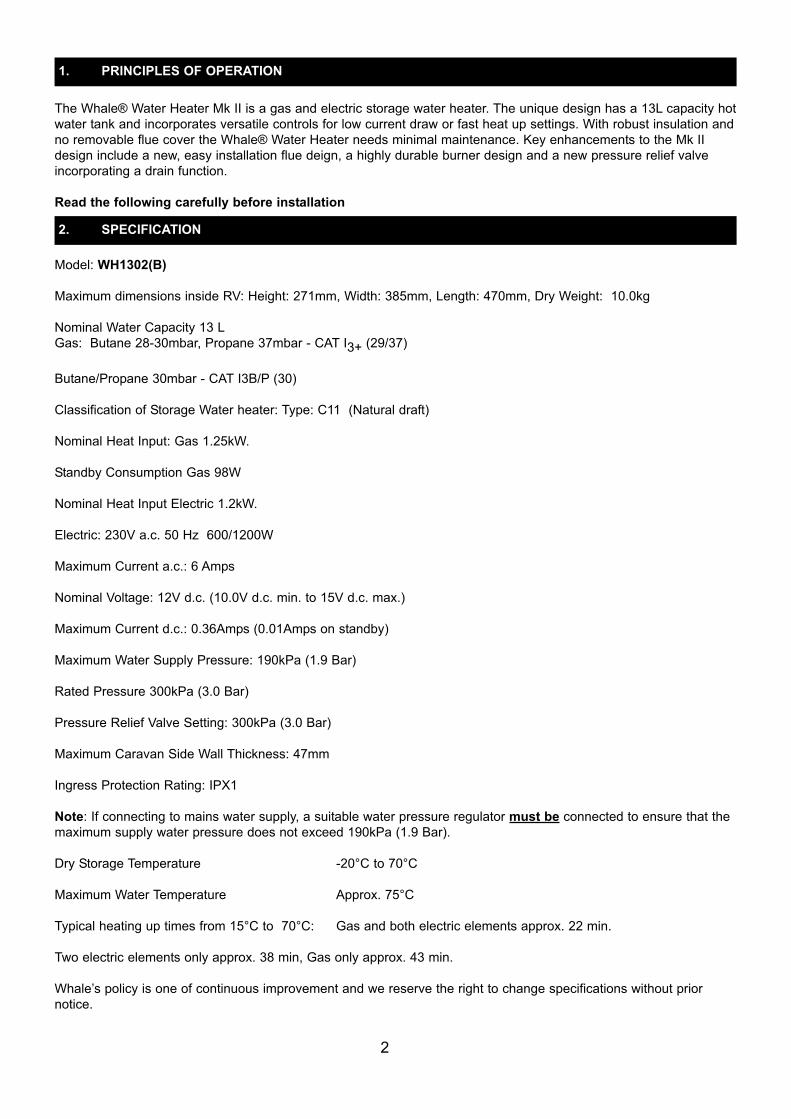
Model: WH1302(B)Maximum dimensions inside RV: Height: 271mm, Width: 385mm, Length: 470mm, Dry Weight: 10.0kgNominal Water Capacity 13 LGas: Butane 28-30mbar, Propane 37mbar - CAT I3+ (29/37)
Butane/Propane 30mbar - CAT I3B/P (30) Classification of Storage Water heater: Type: C11 (Natural draft)Nominal Heat Input: Gas 1.25kW. Standby Consumption Gas 98W Nominal Heat Input Electric 1.2kW.Electric: 230V a.c. 50 Hz 600/1200WMaximum Current a.c.: 6 AmpsNominal Voltage: 12V d.c. (10.0V d.c. min. to 15V d.c. max.) Maximum Current d.c.: 0.36Amps (0.01Amps on standby)Maximum Water Supply Pressure: 190kPa (1.9 Bar) Rated Pressure 300kPa (3.0 Bar) Pressure Relief Valve Setting: 300kPa (3.0 Bar)Maximum Caravan Side Wall Thickness: 47mm Ingress Protection Rating: IPX1Note: If connecting to mains water supply, a suitable water pressure regulator must be connected to ensure that themaximum supply water pressure does not exceed 190kPa (1.9 Bar).Dry Storage Temperature -20°C to 70°CMaximum Water Temperature Approx. 75°CTypical heating up times from 15°C to 70°C: Gas and both electric elements approx. 22 min. Two electric elements only approx. 38 min, Gas only approx. 43 min. Whale’s policy is one of continuous improvement and we reserve the right to change specifications without priornotice.
2. SPECIFICATION
1. PRINCIPLES OF OPERATION
2

The Whale® Water Heater has been designed for caravan, motorhome and mobile applications, and is more thanadequate for typical recreational vehicle shower. The 13L tank has the capacity to provide two 5 minute showers witha minimal reheat.
This symbol indicates that this appliance is suitable for use in Leisure Accommodation Vehicles.
This symbol indicates that this appliance is not suitable for use in boats.
Observe all warnings.In the unlikely event of leaks in the gas system, or if there is a smell of gas:
• Extinguish all naked flames• Switch off all appliances and do not operate any electrical switches• Open windows and doors for ventilation• Do not smoke• Shut off gas connection
Get the system thoroughly checked by a Whale® Authorised Dealer. The appliance must not be operated while the vehicle is being re-fuelled.This appliance is not intended for use by persons (including children) with reduced physical, sensory or mental capabilities, or lack of experience and knowledge, unless they have been given supervision or instruction concerninguse of the appliance by a person responsible for their safety. Children should be supervised to ensure that they donot play with the appliance. Ensure the caravan water system including water heater is full of water, and the vehicle is level before operating.This appliance must be drained if there is a risk of frost. Frost damage will not be covered by warranty.The water temperature cannot be adjusted. It is automatically set to approximately 70°C to prevent bacteria growth.To avoid scalding, the temperature of the hot water supplied to the taps and showers should be controlled. Do notuse the water as drinking water.Any alteration to the appliance, including flue plate, use of non-Whale® spare parts/accessories and non-observationof the installation and operation instructions shall lead to cancellation of the warranty and exclusion of liability claimsand results in it becoming illegal to use the appliance.Please note that incorrect installation or use of non original Whale® parts may invalidate the warranty. It alsobecomes illegal to use the appliance if incorrectly installed, and in some countries this even makes it illegal to usethe vehicle.
3. APPLICATION
4. WARNINGS
3

5. PARTS LIST
4
The Whale® Water Heater kit contains:1 Water Heater and 4 screws1 Flue Assembly and 8 screws1 Control panel and 4 screws3.5m Control panel cable (retail only)1 Hot water flexible connector1 Pressure Relief / Drain Valve Assembly1 Male Adaptor 3/8” flexible hose plumbing fitting2 Male Adaptor ½” flexible hose plumbing fitting1 Warranty registration card1 Instruction manual including installation templates1 Instruction manual storage pocket, with adhesive fixing strip
Fig.1

To the Fitter:Before installation, ensure the appliance has been supplied in good condition and if damaged do not install. A competent person should install the appliance in accordance with the appliance installation instructions. This appliance is for use with LPG (see appliance data plate) and mains electricity (230V a.c.). Check that the product issuitable for the intended application, in particular the installer must check the compatibility of the data plate information with the LPG supply requirements of the vehicle. Follow these installation instructions and ensure all relevant personnel read the points listed below. Also ensure that these operating instructions are passed on to theend user. Please note: The appliance should be installed in accordance with any relevant regulations in the country where theappliance is installed. For this appliance in Europe the standard is BS EN 1949:2002 “Specification for the installationof LPG systems for habitation purposes in leisure accommodation vehicles and in other road vehicles”.
6. INSTRUCTIONS FOR INSTALLATION
5
Fig. 2
Fig. 4
Fig. 3
Side Wall
Floor
42249 30
240 (Cut out in wall)
277
10 21
Side Wall
Gas In
335
470
135 (Cut
out in
wall)
160
360
385
90
Cold water in
Drain valve discharge pipe
Hot water out
Drain valve operating lever
271

Step 1 Find suitable location for Water Heater InstallationConsider the following 4 points:
i. For weight distribution in caravans, aim to position the Water Heater as near to the axle as possible. You must avoid locating at the very rear and preferably avoid the very front.
ii. Ensure the position allows access for servicing the Water Heater. iii. In selecting the Water Heater position, ensure that the flue will be located on a flat and exposed out
side surface, avoiding trim strips.iv. Ensure the pressure relief / drain valve discharge pipe can be located through the floor without
fouling chassis members etcv. Only the supplied flue terminal is permitted to be used and must not be positioned within 300mm of a
refuelling point or fuel tank breather outlet or any ventilator from the fuel system(s). The flue terminal must not be fitted within 300mm of a ventilator for the living space or an opening part of a window.
Fig. 5
The flue terminal may be positioned vertically below an opening part of a window if the appliance is fitted with anautomatic shut-off device to prevent operation when the window is open. It must still be a minimum of 300mm belowthe window. Step 2 Cut out hole for flue See the flue template supplied with the heater. Position template on the inside of the wall with side ‘A’ visible, then drill hole at centre position marked ‘X’ on the template. Position the template on the outside of the wall with side B visible, locate over the drilled position hole ‘X’, and ensurethe template is level. Ensure that the flue outline ison a flat surface avoiding trimstrips etc. If the flue needsmounted in a higher position,the water heater mountingboard can be raised to suitprovided there is sufficientheight available.Drill four 6mm corner holesand cut aperture using fluetemplate as a guide.
6Fig. 6 Fig. 7
Fuel refuelling / breather vent

Reinforce the cut out with wooden batons (minimum 20mm wide).This mayrequire insulation in the wall to be removed.
Fig. 8
Step 3 Attaching the flue to the caravanApply sealant to seal flue on the caravan side wall of the flue sealing face, ensuring each screw hole is surrounded by sealant. Secure flue with the 6 screws (No. 8 x 3/4”) provided and remove excess sealant.
Step 4 Attaching the flue cover Clip the top of the flue cover onto the back box and secure with two screws (No.6 x 1/2”) provided.
Fig. 11
Step 5 Connect Water Heater to flue. Set water heater on the floor and slide fully into flue as shown (see Fig. 12).
7
Fig. 10Fig. 9

Fig. 12 Fig. 13Step 6 Fitting the Drain Pipes (see Fig. 14)With the Water Heater in place on the floor, mark a location for where the pressure relief / drain valve discharge pipewill come through the floor. Carefully remove the heater and drill a hole in the floor, minimum diameter 20mm, ensuring that there are no obstructions on the underside of the vehicle i.e. gas pipes, chassis members etc. Refit theheater, inserting the discharge pipe in the hole and ensure it is left open to the atmosphere at all times.
Fig. 14
Step 7 Secure Water Heater to floor with 4 screws (No. 8 x 1 ¼“) provided (see Fig. 15)
Fig 15
8
Pressure relief / drain valve discharge pipe Discharge pipe

Step 8 Connect to gas supply (see Fig. 16)Ventilation must comply with relevant local requirements e.g. EN 721. Valve and connection are not part of the kit.
Fig. 16
The appliance should be installed in accordance with the installation instructions and comply with any relevant regulations in the country where the appliance is installed.The supply pipe should be checked and free from dirt or other particles before connection to the 8mm gas inlet pipeon the water heater with a compression joint. The supply pipe should be routed so that the appliance can beremoved for servicing. Gas shut off valve should be located in the vicinity of the water heater and all connections should be kept to a minimum.WARNING: The operating pressure for the gas supply should be either 28-30mBar Butane or 30mbar/37mbarPropane.Step 9 Mounting of Whale® Control Panel (see Figs. 17-19)When mounting the Whale® control panel find a suitable convenient and accessible position. Ensure suitable accessfor wiring loom connection and cable. Note that the cable supplied to connect the control panel to the water heater is3.5m long. The minimum depth behind panel for wiring must be 50mm. If using a control panel specific to the manufacturer or the vehicle the electrical connections must be made in accordance with step 10. The control panel requires a cut out 45mm high x 35mm wide. Feed the wires through the control panel mountingframe (see Fig.17) and line up the holes with the control panel. Feed the wires through the cut out in the wall andlocate into desired position. Secure with 2 screws (No.4 x 3/4) provided, then clip on the surround frame.In some instances, it may be necessary to make the wiring connections in step 9 before securing the control panel tothe wall. Please note: It may be possible to retrofit the Whale® control panel into existing frames.
Fig. 17 Fig. 18 Fig. 19
9
Discharge pipe
Pressure relief / drain valve discharge pipe

Step 10 Electrical Connections 12VManufacturer InstallationWARNING: Always disconnect the appliance from the power supply prior to working on electrical components.The water heater and control panel come complete with electrical connectors fitted.The Whale® water heater and control panel are designed to be integrated into the caravan’s wiring loom. The waterheater is provided with a JST VL series 8 way socket, and the control panel with a JST VL 6 way socket. 6 wires arerequired to connect the water heater to the control panel, and 12V and 0V power supply are to be connected to the 8way socket.Please note: We recommend that a 5 amp fuse is fitted in the 12V supply.
Retail installation (see Fig. 20)The water heater and control panel come complete with electrical connectors fitted.Connect the 8 way electrical connector to the 8 way connector on the water heater, then route the wire to the controlpanel and connect the 6 way electrical connector to the 6 way connector at the control panel. Secure the 6 way wireclose to the control panel so there is no strain on the wires at the switches. Connect the red flying lead coming fromthe 8 way connector to a 12V supply; then connect the white flying lead to the caravan 0V. Please note: We recommend that a 5 amp fuse is fitted in the 12V supply.
Fig. 20
10
Wire Number Description Wire Colour1 Switch common Brown2 Burner switch Blue3 Immersion 1 switch Green4 Immersion 2 switch Grey5 Burner LED Orange6 Lockout LED Violet7 12v supply Red8 0v supply White

Step 11 Electrical Connection 230VThe appliance should be installed in accordance with the installation instructions and comply with any relevant regulations in the country where the appliance is installed. Electrical installation should be carried out by a suitablyqualified electrician. The electrical supply must be connected to a 10 amp fused spur provided with an all-pole disconnection and the appliance must be earthed.If the supply cord is damaged, it must be replaced by a special cord or assembly available from the manufacturer orits service agent.Manufacturer Installation Example (see Fig. 21)The mains supply cable is supplied with a JST LP series socket (terminal pins are JST slm-61T-2.0) and must bemounted in a housing with strain relief to prevent accidental disconnection and prevent access to the connector.
Fig. 21Retail Installation (see Fig. 22)The Whale® water heater comes fitted with a 3 pin plug. We recommend that the socket should be mounted vertical-ly and away from potential exposure to water. If installation of an electrical socket is required this must be carried outby an approved electrician. The plug is fitted with a 13 amp fuse.
Fig. 22Step 12 Connection to Cold Water Supply (see Figs. 23 & 24)The Whale® Water Heater is fitted with a Whale® 12mm Quick connect fitting on the cold water inlet to fit to Whale®semi rigid tubing. Various plumbing adaptors are included to assist with these connections as follows: To connectdirectly to 10mm (3/8”) flexible tubing, use 3/8” Stem Adaptor (WU1280) and secure with a hose clip. For connectingto 13mm (1/2”) use ½” Stem Adaptor (WU1282) and secure with a hose clip. For any other plumbing systems contactWhale® Support for further information.
Fig. 23 Fig.24Important: Do not operate the appliance without the installed pressure relief device attached to the heater
11

Please note: A non return valve (not supplied) can be fitted before the pressure relief valve to prevent back flow ofhot water to cold water taps. Step 13 Connect Hot Water Supply (see Figs. 25 & 26)Screw in the braided hose supplied into the hot water outlet and tighten with a 19mm spanner. The outlet of thebraided hose has a 12mm stem which can be connected to a number of different pipe systems with the included fittings as follows.To connect the braided hose to Whale® 12mm semi rigid tubing use Whale® Equal Straight fitting (WU1204) asshown Fig.26. To connect directly to 10mm (3/8”) flexible tubing, no additional fittings are required, push the hoseover the 12mm nipple on the end of the braided hose and secure with a hose clip. For connecting to 13mm (1/2”)flexible tubing use Equal Straight fitting (WU1204) and ½” Stem Adaptor (WU1282).If you have any other plumbing system contact Whale® Support for further information.Please note: The hot water flexible braided hose must always be used to ensure safe operation.
Fig. 25 Fig. 26Step 14 Completed installation (see Figs. 27 & 28)
Typical Manufacturer’s Installation Typical Retail Installation
Fig. 27 Fig. 28Please note: After completing installation carry out a full function check including gas soundness to ensure appliancehas be installed and operates correctly. The gas soundness check must be carried out by an accredited LPG gasengineer and a test certificate issued.
12

To the User: Read the following instructions carefully.Observe all warnings.Never operate the water heater without water in it. This appliance must not be connected directly to the mains watersupply without a pressure regulator fitted, or any water supply greater than 190 kPa (1.9 bar). Ensure the caravanwater system including water heater is full of water, and the vehicle is level before operating.When using operating switches provided by the installer or manufacturer, they are responsible for providing userinstructions and identification of symbols on the control panel.OPERATING INSTRUCTIONSFor operation of the heater, a 12V d.c. supply must be connected at all times. To operate the heater’s electric elements, it must also be connected to a suitable 230V a.c. supply. Upon initial operation, or to refill after the system has been drained, check the drain valve is closed then fill the system with clean fresh water. To fill, open one hot tap and switch on the water pump. Leave the tap open to allow airto escape while the water heater is filling. Once water flows smoothly out of the hot tap, the water heater is filled. Toallow the remainder of air to escape from the system open each hot water tap in turn until water flows smoothly. Please note: In cold temperatures, the water in the supply pipework may freeze and prevent filling.Check that all the gas and/or electricity supplies are turned on.Gas operation. Operate the left-hand switch to the on (flame) position. There will be a pre-purge pause of approx. 5seconds to allow any un-burnt gas to leave the flue and will extinguish when the water is up to temperature. A greenLED will light upon successful flame ignition. If there is air in the gas supply line it may take a few attempts for thegas to ignite. See section 9 for gas lockout re-setting. If the ignition is not satisfactory, the red LED will flash - refer tothe trouble shooting guide (see section 9).Electric operation. The water heater is equipped with twin 600W / 1200 W. immersion heater elements offeringoperation at 600W or 1200W. Operate the right-hand rocker switch to the top position (~) to turn on one electric element. To turn on both electric elements, operate the right-hand rocker switch to the bottom positon Note: The electric elements will still operate if the appliance is in gas ignition lock-out.Gas and electric operation. For faster heating the appliance can be operated with both gas and electric. Switching appliance off. Operate the left-hand gas switch to the top Off position (O) and the right-hand electricrocker switch to the centre position (O). If the heater is not going to be used for some time, isolate the gas supplyand drain water if there is a risk of freezing.Please Note: The water may drip from the discharge pipe of the pressure-relief valve during heating up. This pipemust be left open to the atmosphere, must be installed in a continuously downward direction and in a frost free environment. The pressure relief valve must be operated regularly (at least twice a year) by turning the yellow leverin the clock wise direction, to remove lime deposits and to verify that it is not blocked. General safety notes: The operating pressure of the gas supply to the water heater should be 28-30mBar Butane or30mbar /37mbar Propane.
To clean and sterilise inside the water heater use diluted sterilising fluid and fully rinse through with clean water afterwards. The outside of the appliance should not normally require cleaning. If it does, isolate the electrical suppliesand wipe down with a soft, damp cloth only. Allow to fully dry before reconnecting the electrical supplies.If descaling of this appliance is required, this can be done using ‘Kettle Klear’ or an equivalent product and fully rinsethrough with clean water afterwards.The Whale® Water Heater should be checked periodically by a Whale® Authorised service engineer, or competent person, at least annually. This should be completed according to the practice in the country where it is used andaccording to the Whale® instructions. We recommend annual testing of gas soundness and combustion by an accredited LPG gas engineer.
13
7. INSTRUCTIONS FOR USE
8. MAINTENANCE

The heater is equipped with an electronic diagnostic system which will detect fault conditions ranging from poor gasor d.c. supply to internal heater malfunctions. In the event of a failure, the red light on the control panel will flash anumber of times, pause, and repeat until switched off. Count the number of flashes and refer to the table below.
Gas LockoutsGas lockouts must be cleared by moving the gas switch from on position to off position then back to the on position.The complete sequence of switch movements must be completed within 2.5 seconds for a lockout to be successfullycleared. If there is air in the gas line, e.g. after a gas bottle change, the water heater may require several attemptsbefore it lights.Other LockoutsIf the lockout is caused when the unit is operated on electric, the lockout can be cleared by moving the electric switchfrom on position to off position then back to the on position. The complete sequence of switch movements must becompleted within 2.5 seconds for a lockout to be successfully cleared.Note: A cycling of the power supply to the unit will not clear a lockout. Some gas lockouts, e.g. ignition lockout willstill permit use of the appliance in electric only operation.If the problem persists contact Whale® Support on +44 (0)845 217 2933
When using the heater in winter ensure the flue is not blocked by snow or fallen leaves etc. When not in use, ensurethe heater is drained. This is particularly important during the winter months as a precaution against freezing. Todrain, switch off the water pump at either the pump switch or main switch. Open all the hot water taps in the vehicleand operate the drain valve fitted in the system. The drain valve should be left in the open position to ensure all thewater drains out.
For installation or serviceable parts advice please contact Whale® Customer Support:Tel: +44 (0)845 217 2933Email: [email protected]
Number offlashes Fault Remedy
1 No flame detected
2 Overheat
3 Low/high supply voltage
5 Other / internal fault
14
9. TROUBLE SHOOTING
Check gas supply making sure there is gas in the bottle and noblockage in the gas line. Ensure propane is used at temperaturesbelow +5°C. Clear lockout as described below.Check there is water in the appliance. We recommend you wait atleast 5 to 10 minutes to allow the heater to cool before clearinglockout as described below.Minimum operating voltage is 10V, maximum is 15V, when meas-ured at the heater. Check battery voltage. If between 10V and 15V,check connections between heater and battery. Check alternator or external battery charging. Clear lockout as described below.Attempt to clear lockout as shown below. If this fails, contact aWhale Authorised Service Engineer.
10. WINTERISING / DRAINING
11. SERVICE SUPPORT DETAILS

Description of Equipment: Gas and Electric Storage Water HeaterManufacturer’s DeclarationWe hereby declare, under our sole responsibility, that the above equipment complies with the provisions of the following EC Directives:Gas Appliance Directive 2009/142/EC on the approximation of the laws of the Member States relating to appliancesburning gaseous fuels. Low Voltage Directive 2006/95/EC on the harmonization of the laws of the Member States relating to electrical equipment designed for use within certain voltage limits.Electromagnetic Compatibility Directive 2004/108/EC, on the approximation of the laws of the Member States relatingto electromagnetic compatibility.
CE mark first affixed: June 2009Basis on which conformity is declaredThe above equipment meets the protection requirements of the EMC Directive and the principal elements of the safe-ty objectives of the Low Voltage Directive.Please contact Whale® if further details are required. Signed
Stanley McFarlandEngineering Director
The Whale® Water Heater is protected by the following patent and design registration applications:UK Patent application number: 0902533.9
The Whale® Water Heater is covered by a 3 year warranty. Please complete the enclosed warranty card and return to Whale.For warranty details, please see the enclosed warranty statement.
Munster Simms Engineering Ltd.Old Belfast Road, Bangor, N. Ireland BT19 1LT Tel: +44 (0)28 9127 0531 Fax: +44 (0)28 9146 6421www.whalepumps.comEmail: [email protected]
15
12. EU DECLARATION OF CONFORMITY
13. PATENTS AND TRADEMARKS
14. WARRANTY

Ref: 181.192_v1_0611