Embed Size (px)
Citation preview

• gorenJe
gorenje
OGB 30-200 SEDDN9
Dear buyer, we thank you for purchase of our product. I Prior to installation and first use of the electric water heater, please carefully read these instructions.
THIS APPLIANCE IS NOT INTENDED FOR USE BY PERSONS (INCLUDING CHILDREN) WITH REDUCED PHYSICAL, SENSORY OR MENTAL CAPABILITIES, OR LACK OF EXPERIANCE AND KNOWLEDGE, UNLESS THEY HAVE BEEN GIVEN SUPERVISION OR INSTRUCTION CONCERNING USE OF THEAPPLIANCE BY PERSON RESPONSIBLE FOR THEIR SAFETY. CHILDREN SHOULD BE SUPERVISED TO ENSURE THAT THEY DO NOT PLAY WITH THE APPLIANCE.
This water heater has been manufactured in compliance with the relevant standards and tested by the relevant authorities as indicated by the Safety Certificate and the Electromagnetic Compatibility Certificate. The technical characteristics of the product are listed on the label affixed between the inlet and outlet pipes. The installation must be carried out by qualified staff. All repairs and maintenance work within the water heater, e.g. lime removal or inspection/replacement of the protective anticorrosion anode, must be carried out by the authorised maintenance service provider.
BUILDING-IN
The water heater shall be built-in as close as possible to the outlets. When installing the water heater in a room with bathtub or shower, take into account requirements defined in IEC Standard 60364-7-701 (VDE 0100, Part 701 ). It has to be fitted to the wall using appropriate rag bolts with minimum diameter of 8 mm. The wall with feeble charging ability must be on the spot where the water heater shall be hanged suitably reinforced. The water heater may be fixed upon the wall only vertically.
TECHNICAL PROPERTIES OF THE APPLIANCE
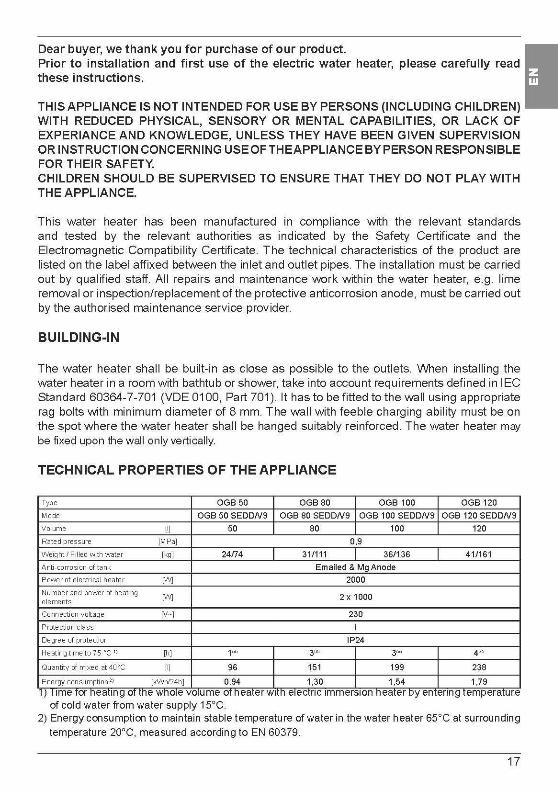
Type OGB50 OGB80 OGB 100 OGB 120 Model OGB 50 SEDDN9 OGB 80 SEDDN9 OGB 100 SEDDN9 OGB 120 SEDDN9 Volume [I] 50 80 100 120 Rat ed pressure [MPa] 0,9 Weight I Filled IMth water [kg] 24/74 31/111 36/1 36 41/161 A nti .corrosion of tank Emailed & Mg Anode Power of electrical heater ['N] 2000 Number and power of heating
['N] 2 x 1000 elements
Connection voltage [V- J 230 Protection class I Degree of protection IP24 Heating time t o 75 °( 1) [h] 1" 3"' 3" 4" Quantity of rrixed at 40°C [I] 96 151 199 238 Energy consumption2) [kWhl24h] 0,94 1,30 1,54 1,79
1) lime Tor neat1ng oT me wno1e volume orneater w1m e1ectnc 1mmers1on neater oy entering temperature of cold water from water supply 15°C.
2) Energy consumption to maintain stable temperature of water in the water heater 65°C at surrounding temperature 20°C, measured according to EN 60379.
17
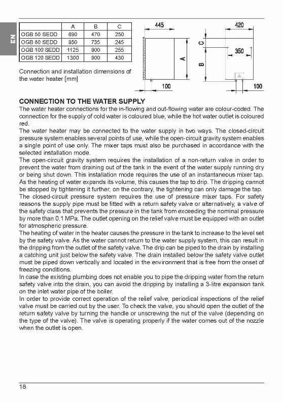
I A B c
OGB 50 SEDD 690 470 250
OGB 80 SEDD 950 735 245
OGB 100 SEDD 1125 900 255
OGB 120 SEDD 1300 900 430
Connection and installation dimensions of the water heater [mm]
CONNECTION TO THE WATER SUPPLY
445 420
(.)
I 350 r < I I
GJ
r 100 I I 100 I I I
The water heater connections for the in-flowing and out-flowing water are colour-coded. The connection for the supply of cold water is coloured blue, while the hot water outlet is coloured red. The water heater may be connected to the water supply in two ways. The closed-circuit pressure system enables several points of use, while the open-circuit gravity system enables a single point of use only. The mixer taps must also be purchased in accordance with the selected installation mode. The open-circuit gravity system requires the installation of a non-return valve in order to prevent the water from draining out of the tank in the event of the water supply running dry or being shut down. This installation mode requires the use of an instantaneous mixer tap. As the heating of water expands its volume, this causes the tap to drip. The dripping cannot be stopped by tightening it further; on the contrary, the tightening can only damage the tap. The closed-circuit pressure system requires the use of pressure mixer taps. For safety reasons the supply pipe must be fitted with a return safety valve or alternatively, a valve of the safety class that prevents the pressure in the tank from exceeding the nominal pressure by more than 0.1 MPa. The outlet opening on the relief valve must be equipped with an outlet for atmospheric pressure. The heating of water in the heater causes the pressure in the tank to increase to the level set by the safety valve. As the water cannot return to the water supply system, this can result in the dripping from the outlet of the safety valve. The drip can be piped to the drain by installing a catching unit just below the safety valve. The drain installed below the safety valve outlet must be piped down vertically and located in the environment that is free from the onset of freezing conditions. In case the existing plumbing does not enable you to pipe the dripping water from the return safety valve into the drain, you can avoid the dripping by installing a 3-litre expansion tank on the inlet water pipe of the boiler. In order to provide correct operation of the relief valve, periodical inspections of the relief valve must be carried out by the user. To check the valve, you should open the outlet of the return safety valve by turning the handle or unscrewing the nut of the valve (depending on the type of the valve). The valve is operating properly if the water comes out of the nozzle when the outlet is open.
18
~T~--\ \ \ ~ 7 2 3 6 4 5
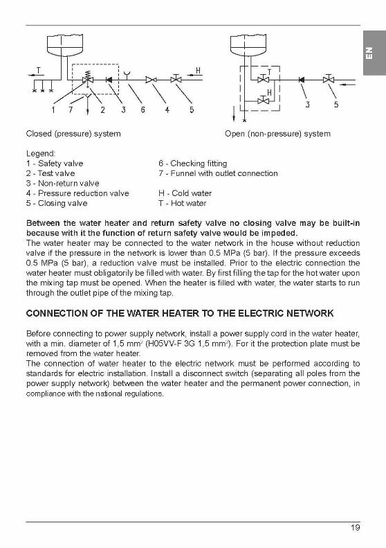
Closed (pressure) system
Legend: 1 - Safety valve 2 - Test valve 3 - Non-return valve 4 - Pressure reduction valve 5 - Closing valve
Open (non-pressure) system
6 - Checking fitting 7 - Funnel with outlet connection
H - Cold water T - Hot water
Between the water heater and return safety valve no closing valve may be built-in because with it the function of return safety valve wou Id be impeded. The water heater may be connected to the water network in the house without reduction valve if the pressure in the network is lower than 0.5 MPa (5 bar). If the pressure exceeds 0.5 MPa (5 bar) , a reduction valve must be installed. Prior to the electric connection the water heater must obligatorily be filled with water. By first filling the tap for the hot water upon the mixing tap must be opened. When the heater is filled with water, the water starts to run through the outlet pipe of the mixing tap.
CONNECTION OF THE WATER HEATER TO THE ELECTRIC NETWORK
Before connecting to power supply network, install a power supply cord in the water heater, with a min. diameter of 1,5 mm2 (H05VV-F 3G 1,5 mm2). For it the protection plate must be removed from the water heater. The connection of water heater to the electric network must be performed according to standards for electric installation. Install a disconnect switch (separating all poles from the power supply network) between the water heater and the permanent power connection, in compliance with the national regulations.
19
I

I Legend: 1 - Electronic thermostat 2 - Bipolar thermal fuse 2 - Electric heater 5 - Connection terminal
L - Live conductor N - Neutral conductor ...L . -=- - Earthing conductor
~ NL
L ___ _J L _ _J
Electric installation
CAUTION: Prior to each reach in the inner of the water heater it must absolutely be disconnected from the electric network!
OPERATION AND MAINTENANCE
After connecting to water and power supply, the heater is prepared for use.
The water heater features an that enables of water temperature of in water heater tank. The electronic regulator allows manual adjustment of temperature in range from 35°C to 75°C, settings to cost saving operation mode and temperature adjustment to prevent freezing. Electronic regulator display shows the current temperature of water in water heater.
OPERATION CONTROL:
The heater is switched ON and OFF by pressing the ~ key for 2s.
Continue pressing the @ key and select the three operating modes:
- ~protection against freezing (factory water temperature set to 7°C)
e cost saving operation (factory set to 55°C)
- ~optional manual setting of temperature in the range from 35°C to 75°C (increments of 1oq
20

Protection 3lainst freezing: I - Use the ~ key and select the ~operating mode (yellow control lamp under~ 1s on)
The regulator 1s set to temperature 7°C - shown on the display
Cost saving operating mode:
- Use the @ key and select thee operating mode (yellow control lamp under e is on) - The regulator is set to temperature 55°C - shown on the display
Manual temperature setting:
- Use the @ key and select the~ operating mode (yellow control lamp under~ is on). - The display always shows the last setting of the water temperature; except on first turn on
of appliance when factory setting 35°C is displayed.
- Use the @ or @ key to select new temperature. By pressing the key you increase/ decrease the temperature by 1°C. Holding the key will speed up the process.
- After required temperature is set display flashes for 3 seconds and then shows the current temperature again.
- In case of interruptions in power supply, the appliance resumes operating with the settings adjusted before the interruption.
INQICATION·
Control lamps:
- Heating element operation &: Green control lamp: the heating element is on - the lamp is on the heating element is off - the lamp is off
Mg anode ©=i:;I: Red control lamp: the lamp is off - anode is active the lamp is on - anode may be worn out
Warning! When the water heater is out of use for longer period of time, the signal lamp may indicate that the Mg anode is worn out in spite of the fact that the Mg anode is still active. In this case open the hot water tap (fresh water flow into water heater). If the signal lamp switches off, the water heater operation is not impaired. If not, call the nearest authorized service provider
Water heater operation: Yellow control lamps: protection against freezing - the lamp is on or cost saving temperature setting - the lamp is on or manual setting- the lamp is on
21

I LED display:
Water temperature of in the heater. from 0°C to 75°C When set, display of the adjusted temperature: (flashing from 0°C to 75°C) Error indication:
display E1 - failure of the electronic regulator sensor (the heating element doesn't operate) display E2 - failure of the thermometer sensor (water heater operates) display E3 - failure of both sensors (water heater doesn't operate) display E4- low temperature, freezing (water heater doesn't operate) display E5 - overheating (temperature> 100°C) - (failure of electronic regulator)
VVhen the water heater is not in use for longer periods of time, it should be protected from freezing by setting the temperature to"*". Do not disconnect the power. Thus the temperature of water is maintained at about 10°C. Should you choose to disconnect the power, the water heater should be thoroughly drained before the onset of freezing conditions. Water is discharged from heater via the inlet pipe. To this purpose, a special fitting (T-fitting) must be mounted between the relief valve and the heater inlet pipe, or a discharge tap. The heater can be discharged directly through the relief valve, by rotating the handle or the rotating valve cap to same position as for checking the operation. Before discharge, make sure the heater is disconnected from the power supply, open the hot water on the connected mixer tap. After discharging through the inlet pipe, there is still some water left in the water heater. The remaining water will be discharged after removing the heating flange, through the heating flange opening. The external parts of the water heater may be cleaned with a mild detergent solution. Do not use solvents and abrasives. Regular preventive maintenance inspections ensure faultless performance and long life of your heater. The first of these inspections should be carried out by the authorised maintenance service provider about two years from installation in order to inspect the wear of the protective anticorrosion anode and remove the lime coating and sediment as required. The lime coating and sediment on the walls of the tank and on the heating element is a product of quality, puantity and temperature of water flowing through the water heater. The maintenance service provider shall also issue a condition report and recommend the approximate date of the next inspection.
Never try to repair any possible faults of the water heater by yourself, but inform about it the nearest authorised service workshop.
22


![SEDD-i ZERAi'SEDD-i ZERAi' 'iyyeden biri olarak nitelendirilmektedir ( sedd-i zeraiin delil, asl, kaide ve bazı çağ daş yazarlarca prensip [mebde] şeklinde nitelendirilmesi için](https://img.dokumen.tips/doc/110x75/605923bda0d6e2198442a613/sedd-i-zerai-sedd-i-zerai-iyyeden-biri-olarak-nitelendirilmektedir-sedd-i-zeraiin.jpg)