Embed Size (px)
Citation preview
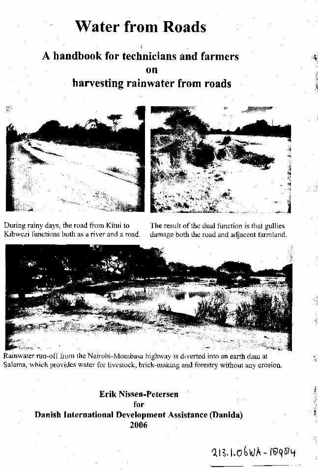
Water from Roads• * • •
' • •
A handbook for technicians and farmerson
harvesting rainwater from roads
During rainy days, the road from Kitui to The result of the dual function is that gulliesKibwezi functions both as a river and a road, damage both the road and adjacent farmland.
Rainwater run-off from the Nairobi-Mombasa highway is diverted into an earth dam atSalama, which provides water for livestock, brick-making and forestry without any erosion.
Erik Nissen-Petersenfor
Danish Internationa] Development Assistance (Danida)2006
Water from Roads
A handbook for technicians and farmerson
harvesting rainwater from roads

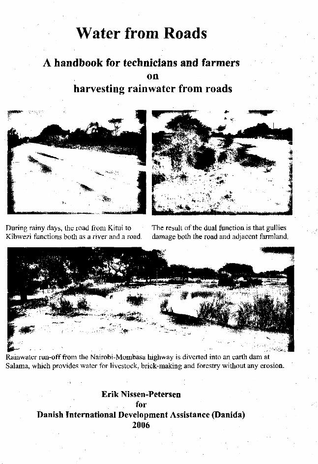
Water from Roads
A handbook for technicians and farmerson
harvesting rainwater from roads
During rainy days, the road from Kitui to The result of the dual function is that gulliesKibwezi functions both as a river and a road, damage both the road and adjacent farmland.
Rainwater run-off from the Nairobi-Mombasa highway is diverted into an earth dam atSalama, which provides water for livestock, brick-making and forestry without any erosion.
Erik Nissen-Petersenfor
Danish International Development Assistance (Danida)2006


Technical handbooks in this series :
litles Contentsi Water for rural communities Lessons learnt from Kitui pilot projects' Water supply by rural builders Procedures for being rural contractorsi Water surveys and designs Survey, design and cost of water projects• Water from rock outcrops Rock catchment tanks, masonry and earth dams' Water from dry riverbeds Wells, subsurface dams, weirs and sand dams• Water from roads Rainwater harvesting from roads' Water from small dams Ponds and small earth dams built manually: Water from roofs Various types of roof catchments for domestic use
hese handbooks can be obtained free of charge by either collecting them from the office of\SAI_ Consultants Ltd., or by paying through bank transfer the cost of sending the manuals by:ourier. For further details, please contact: [email protected] with copy toisalconsultants(5)vahoo.com
Published by-.SAL Consultants Ltd. forhe Danish International Development Assistance (Danida) in Kenya
ext, sketches and photos byrik Nissen-Petersen
•omputer drawings byCatherine W. Wanjihia
diting and proofs byrof. Elijah K. Biamah, Amin Verjee and Steen S. Larsen
"rinterrintwell Ind. Ltd., P.O. Box 5216-0506, Nairobi, Kenya
Vebsite bydwin Ondako
•istribution by -.SAL Consultants Ltd. P.O. Box 739, Sarit 00606, Nairobi, [email protected] [email protected]/Tel : 254 020 2710296 and 4766144 Mobiles: 0733 619 066 and 0722 599 165.'ebsite : www.waterforaridland.com
' Copyright.
he copyright of this handbook is the property of the Royal Danish Embassy in Kenya,ownloading from the internet and photocopying of the handbooks is permitted provided•e source is acknowledged.

Contents Page
Acknowledgement viiForeword viiiTechnical vocabulary ixMeasurements and conversions x
Chapter 1. Damage by road run-off water 11.1 Road damage by run-off 11.2 Loss of people and livestock 21.3 Gullies made by culverts 31.4 Volume of rainwater running off roads 41.5 Benefits from rainwater running off roads 5
Chapter 2. Earth dams 62.1 Murram pits 62.2 . Small pans 82.3 Large pans 82.4 Ponds 92.5 Charco dams 92.6 Hillsidedams 102.7 Valley dams 112.8 Tools and equipment for soil works 122.9 Analysis of soil samples 132.10 Construction costs of earth dams 142.11 References on earth dams 14
Chapter 3. Water tanks 153.1 Advantages of water tanks 153.2 Excavation of hemispherical tanks 153.3 Hemispherical tank built of burnt bricks 163.4 Hemispherical tank built of ant-hill soil, lime, sand and cement.... 193.5 Hemispherical tank built of ferro-cement 233.6 Cylindrical underground water tanks 263.7 Berkads 283.8 Rectangular water tanks 333.9 References on water tanks 33
Chapter 4. Subsurface dams 344.1 Water in sand reservoirs 344.2 Floodwater passing roads 344.3 Hand-dug wells 354.4 Subsurface dams, weirs and sand dams 364.5 Subsurface dams built of soil 374.6 Weirs 394.7 Sanddams 404.8 Sand harvesting 444.9 Gold and gem stones from sand dams 454.10 References on subsurface dams, weirs and sand dams 45
Chapter 5. Run-off farming 465.1 Drainage from roads by engineers 465.2 Drainage from roads by farmers . ; 475.3 Soilbunds '. 505.4 Gullies 515.5 Macro-irrigation 555.6 References on run-off farming 57
VI
Acknowledgments
Much gratitude is due to Birgit Madsen of the Royal Danish Embassy in Nairobi forhaving taken a leading role in documenting the experiences of various techniques ofcreating low-cost water supply structures in the semi-desert, arid and semi-aridregions of the world.
Many thanks are also due to Prof. Elijah Biamah, Steen Larsen and Amin Verjee, whoassisted with proof-reading the text and editing, to Edwin Ondako who created thewebsite and loaded this handbook and others onto it, and to Oliver D'Cunha, whomanaged the printing at Printwell Ind.Ltd..
Thanks are also due to the many engineers, technicians, artisans and self help groupswho participated in several training courses and other assignments on small earthdams implemented by ASAL Consultants Ltd. for Danida, S1DA, UNDP, the EU andother organisations in a dozen countries over the last three decades.
This handbook, Waterfront Roads, is one of a series of 8 publications on Water inArid Lands, financed by the Danish International Development Assistance (Danida).
To promote the simple technologies described in the handbooks, these can be read ordownloaded free of charge from our website www.waterforaridland.com .
Erik Nissen-PetersenManaging DirectorASAL Consultants Ltd.P.O. Box 739, 00606, Nairobi, KenyaTel/fax:+254 (0)20 2710296Mobile:+254 (0)733 619066 /+254 (0)722 599144
DisclaimerThe designs and construction procedures described in this handbook are based on theauthor's experiences and observations over 30 years. The tanks and earth damsdescribed herein, when properly constructed and maintained, have performedexceptionally well. However, local climatic, geological, seismic and soil conditionsvary widely, as does the quality of materials and workmanship, and while the authorand Danida are keen to encourage the replication of the ponds and dams described inthis handbook, they cannot accept liability for the failure of a water harvesting systembased on the designs and construction procedures described herein.
vii

Foreword
This handbook on water from roads produced by Danida in Kenya is targeted at allorganizations involved in road construction works and especially the Ministry ofRoads and Public Works.
Currently, all road construction works have no provision for the storage of run-offwater generated from road drainage. This handbook then comes when road engineershave been trained and sensitized on the importance of safe disposal of run-off waterfrom roads.
Water from Roads as a handbook is expected to serve as a guide for road engineersand contractors who are involved in the design and construction of road drainageworks. The handbook provides valuable technological advice for harnessing road run-off water.
This handbook provides all the technical information required for the design andconstruction of all the types of earth dams, water tanks and subsurface dams. Also thehandbook contains information on run-off farming.
It is this understanding of the technical information contained herein that our roadscould be designed better by providing viable alternative technologies options forharnessing road drainage. This handbook also provides alternative technologies forrun-off water utilization.
Mrs Elizabeth MibeyPrincipal Environmental Impact Assessment (EIA) OfficerMinistry of Roads and Public Works
vm
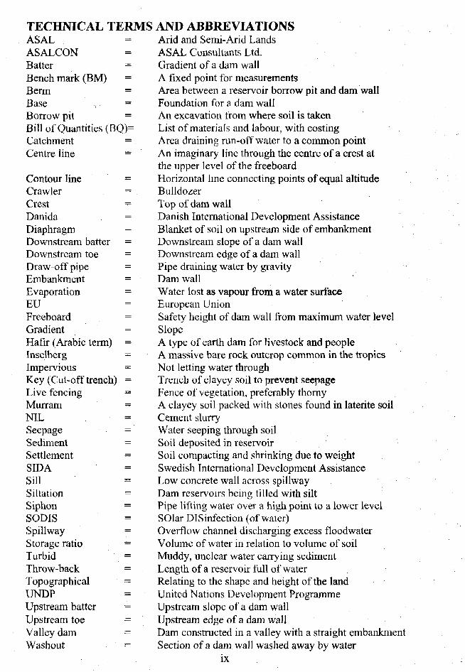
TECHNICAL TERMSASALASALCONBatterBench mark (BM)Berm =Base =Borrow pit =Bill of Quantities (BQ)=Catchment =Centre line =
Contour line =Crawler =CrestDan i da =Diaphragm =Downstream batter =Downstream toe =Draw-off pipe =Embankment =Evaporation =EUFreeboard =Gradient =Hafir (Arabic term) =Inselberg =Impervious =Key (Cut-off trench) =Live fencing =Murram =NILSeepage =Sediment =Settlement =SIDASillSiltation =Siphon =SOD1SSpillway =Storage ratio =Turbid =Throw-back —Topographical =UNDPUpstream batter =Upstream toe = 'Valley dam =Washout =
AND ABBREVIATIONSArid and Semi-Arid LandsASAL Consultants Ltd.Gradient of a dam wallA fixed point for measurementsArea between a reservoir borrow pit and dam wallFoundation for a dam wallAn excavation from where soil is takenList of materials and labour, with costingArea draining run-off water to a common pointAn imaginary line through the centre of a crest atthe upper level of the freeboardHorizontal line connecting points of equal altitudeBulldozerTop of dam wall
Danish International Development AssistanceBlanket of soil on upstream side of embankmentDownstream slope of a dam wallDownstream edge of a dam wallPipe draining water by gravityDam wallWater lost as vapour from a water surfaceEuropean UnionSafety height of dam wall from maximum water levelSlopeA type of earth dam for livestock and peopleA massive bare rock outcrop common in the tropicsNot letting water throughTrench of clayey soil to prevent seepageFence of vegetation, preferably thornyA clayey soil packed with stones found in laterite soilCement slurryWater seeping through soilSoil deposited in reservoirSoil compacting and shrinking due to weightSwedish International Development AssistanceLow concrete wall across spillwayDam reservoirs being tilled with siltPipe lifting water over a high point to a lower levelSOlar Disinfection (of water)Overflow channel discharging excess floodwaterVolume of water in relation to volume of soilMuddy, unclear water carrying sedimentLength of a reservoir full of waterRelating to the shape and height of the landUnited Nations Development ProgrammeUpstream slope of a dam wallUpstream edge of a dam wall
Dam constructed in a valley with a straight embankmentSection of a dam wall washed away by water
ix
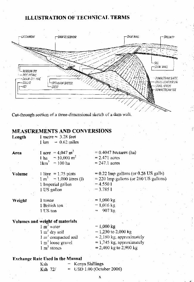
ILLUSTRATION OF TECHNICAL TERMS
r M M WALL
DOWNSTRAM BATTLGRASS CONTOUR UN
- STONk APRON-DOWNSTREAM TOE
; L - BORROW'PIT"— PIPF INTAKE— DUAWOTTPIPF— COLLAR
1
Cut-through section of a three-dimensional sketch of a dam wall.
MEASUREMENTS AND CONVERSIONSLength 1 metre = 3.28 feet
1 km = 0.62 miles
Area 1 acre = 4,047 m1 ha = 10,000 m2
lkm2 =100 ha
Volume 1 litre = 1.75 pintslm 3 =1,000 litres (1)1 Imperial gallon1 US gallon
Weight 1 tonne1 British ton1 US ton
Volumes and weight of materials1 m3 water1 m3 dry soil1'm3 compacted soil1 m3 loose gravel1 m3 stones
= 0.4047 hectares (ha)= 2.471 acres= 247.1 acres
= 0.22 Imp gallons (or 0.26 US galls)= 220 Imp gallons (or 260 US gallons)= 4.5501= 3.785 1
= 1,000 kg= 1,016 kg= 907 kg
= 1,000 kg= 1,230 to 2,000 kg= 2,180 kg, approximately= 1,745 kg, approximately= 2,400 kg to 2,900 kg
Exchange Rate Used in the ManualKsh = Kenya ShillingsKsh 72/ = USD 1.00 (October 2006)
Chapter 1. Damage by road run-off water
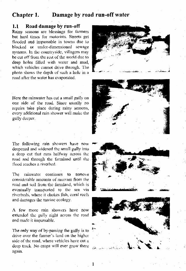
1.1 Road damage by run-offRainy seasons are blessings for farmersbut hard times for motorists. Streets getflooded and impassable in towns due toblocked or under-dimensioned sewagesystems. In the countryside, villagers maybe cut off from the rest of the world due todeep holes filled with water and mud,which vehicles cannot drive through. Thephoto shows the depth of such a hole in aroad after the water has evaporated.
Here the rainwater has cut a small gully onone side of the road. Since usually norepairs take place during rainy seasons,every additional rain shower will make thegully deeper.
The following rain showers have nowdeepened and widened the small gully intoa deep cut that runs halfway across theroad and through the farmland until theflood reaches a riverbed.
The rainwater continues to removeconsiderable amounts of murrain from theroad and soil from the farmland, which iseventually transported to the sea viariverbeds, where it chokes fish, coral reefsand damages the marine ecology.
A few more rain showers have nowextended the gully right across the roadand made it impassable.
The only way of by-passing the gully is todrive over the farmer's land on the higherside of the road, where vehicles have cut adeep track. No crops will ever grow thereagain.

A road-grader has made a cut-off channel todivert run-off water from a road to a field.
While this preserves the road, it damagesthe field, because the run-off water willcreate a gully stretching all the way fromthe road to the nearest riverbed.
After a few years, the run-off water fromthe road will have deepened and widened asmall gully in a fertile farmland to a barevalley where all the top soil has beeneroded. Only hardy thorny scrubs can growthere.
Where no preventive action is taken, asmall gully may turn into a desolate moonlandscape as seen in the photo.
In this way, thousands of acres of fertilefarmland are being washed away every yearby uncontrolled rainwater running offroads.
Another hazard created by rainwaterrunning off roads is that some people andanimals lose their lives, while trying tocross a road over a riverbed flooded byrainwater.
1.2 Loss of people and livestockOften rainwater comes as a flash floodseveral metres high, which carries uprootedtrees and drowned animals - and sometimesdrowned people - into the brown maelstromof flooded riverbeds. The photo shows thedamage by erosion to a low bridge after aflood has passed over it.
This handbook explains in simple terms,how other people have stopped the erosionprocess and improved their living standards. 2
1.3 Gullies made by culverts
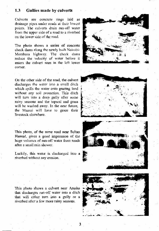
Culverts are concrete rings laid asdrainage pipes under roads at their lowestpoints. The culverts drain run-off waterfrom the upper side of a road to a riverbedon the lower side of the road.
The photo shows a series of concretecheck dams along the newly built Nairobi-Mombasa highway. The check damsreduce the velocity of water before itenters the culvert seen in the left lowercorner.
On the other side of the road, the culvertdischarges the water into a small ditchwhich spills the water onto grazing landwithout any soil protection. This ditchwill turn into a deep gully after somerainy seasons and the topsoil and grasswill be washed away. In the near future,the Maasai will have to graze theirlivestock elsewhere.
This photo, of the same road near SultanHamud, gives a good impression of thehuge volumes of run-off water from roadsafter a small rain shower.
Luckily, this water is discharged into ariverbed without any erosion.
This photo shows a culvert near Arushathat discharges run-off water into a ditchthat will either turn into a gully or ariverbed after a few more rainy seasons.
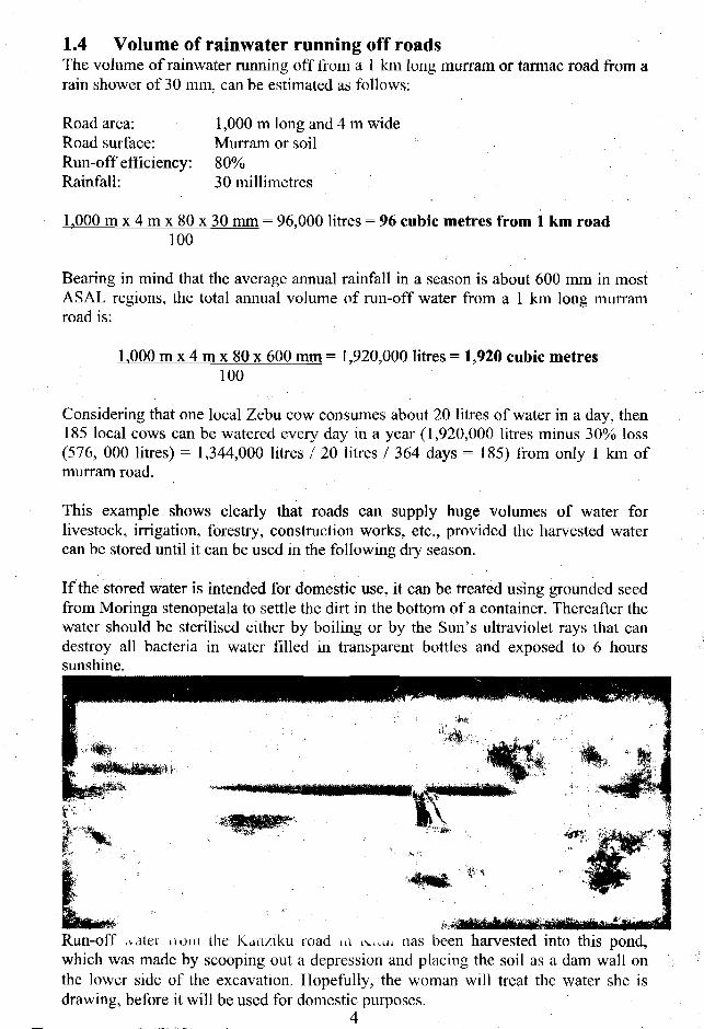
1.4 Volume of rainwater running off roadsThe volume of rainwater running off from a 1 km long murram or tarmac road from arain shower of 30 mm, can be estimated as follows:
Road area:Road surface:Run-off efficiency:Rainfall:
1,000 m long and 4 m wideMurram or soil80%30 millimetres
1.000 m x 4 m x 80 x 30 mm = 96,000 litres = 96 cubic metres from 1 km road100
Bearing in mind that the average annual rainfall in a season is about 600 mm in mostASAL regions, the total annual volume of run-off water from a 1 km long murramroad is:
1.000 m x 4 m x 80x 600 mm= 1,920,000 litres = 1,920 cubic metres100
Considering that one local Zebu cow consumes about 20 litres of water in a day, then185 local cows can be watered every day in a year (1,920,000 litres minus 30% loss(576, 000 litres) = 1,344,000 litres / 20 litres / 364 days = 185) from only 1 km ofmurram road.
This example shows clearly that roads can supply huge volumes of water forlivestock, irrigation, forestry, construction works, etc., provided the harvested watercan be stored until it can be used in the following dry season.
If the stored water is intended for domestic use, it can be treated using grounded seedfrom Moringa stenopetala to settle the dirt in the bottom of a container. Thereafter thewater should be sterilised cither by boiling or by the Sun's ultraviolet rays that candestroy all bacteria in water filled in transparent bottles and exposed to 6 hourssunshine.
Run-off .vater noni the Kanziku road in \uu. has been harvested into this pond,which was made by scooping out a depression and placing the soil as a dam wall onthe lower side of the excavation. Hopefully, the woman will treat the water she isdrawing, before it will be used for domestic purposes.
4

1.5 Benefits from rainwater running off roadsAs shown on the previous page, the 1,344 cu.m. run-off water from 1 km of road canwater 185 local cows every day in a year, while taking into account that 30% of thewater may be lost due to evaporation or seepage. Besides watering livestock, thewater could also be used for other purposes, such as:
1. Tree nurseries, woodlots, orchards and vegetative fencing of fields andhomesteads, which provide income from sale of tree seedlings, timber,firewood, fruits, etc.
2. Manufacturing of burnt bricks, concrete blocks, culverts and other buildingmaterials that can be sold.
3. Sale of water to neighbours for watering their livestock, construction works,etc.
4. Raising ducks, geese, fish and bees in or near open water reservoirs.
5. Sale of sand harvested from weirs and sand dams in gullies and riverbeds.
6. Recharge of hand-dug wells near subsurface dams, weirs and sand dams inriverbeds from where domestic water can be drawn.
7. Using nm-off water from tarmac roads for domestic use is not advisable due tothe risk of contamination by tar, oil, rubber, etc.
8. Increased agricultural production from fields irrigated by road run-off water.
Two examples of school boys earning cash for their schooling:
Harvesting sand for sale from a sand dam Assisting water vendors in bringingbuilt in a gully near Lake Victoria. The empty jerrycans to a water point nearconstruction cost of 10 sand dams was Voi.recovered from sale of sand in 1 Vz years.
The next chapters will describe four types of rainwater harvesting from roads, namelyearth dams, tanks, subsurface dams and run-off farming, which farmers can constructthemselves for a minimum of investment.
5

Chapter 2. Earth dams
The most common technique for harvesting run-off water from roads is to store theharvested water in reservoirs built of soil. The construction cost consists only oflabour to excavate and transport soil. There is no need to purchase cement orreinforcement iron from hardware shops.
Several types of soil structures that can be constructed successfully by farmers aredescribed in the following chapters.
2.1 Murrain pitsMurram pits, also called borrow pits, are always situated along roads and are easy toconvert into water reservoirs, because only excavation of one or two trenches isrequired. However, before digging the trenches, it is advisable to discuss the issuewith the local authorities.
Murram pits are found along most roads,because the material (murram) excavatedfrom them is used for building the roads.Whenever a road is re-carpeted with murram,the existing pits are either widened, or newmurram pits are excavated.
In any case, the floor of murram pits isusually either impermeable laterite or rock,through which there is hardly any seepage. Ifthe walls or the floor of a murram pit arestony they may allow some seepage but thatcan be sealed by plastering a mixture of clayeysoil and lime onto the leaking parts.
A murram pit along a road in Kitui
The run-off water from a road is diverted into a murram pit by excavating a trenchreaching upwards from the murram pit to the ditch running along the road. To preventsedimentation of the water reservoir in the murram pit, the trench should have agradient of about 3 cm for every 100 cm.
Spirit level
Gradient300-
A gradient of 3:100 can be measured WT ' _..:.:t::z=Eby levelling a spirit level on a 300 cm — ^ T^ABATXD
long timber having a leg being 9 cmlong.
This photo shows a cut-off trench that hasbeen cut by a road grader for the purpose ofdiverting run-off water from the road intoan adjacent field. Similar trenches can beexcavated by hand, or ox-scoops, to divertrainwater into murram pits.
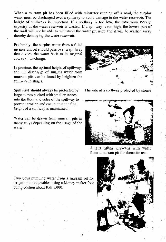
When a murram pit has been filled with rainwater running off a road, the surpluswater must be discharged over a spillway to avoid damage to the water reservoir. Theheight of spillways is important. If a spillway is too low, the maximum storagecapacity of the water reservoir is wasted. If a spillway is too high, the lowest part ofthe wall will not be able to withstand the water pressure and it will be washed awaythereby destroying the water reservoir.
Preferably, the surplus water from a filledup murram pit should pass over a spillwaythat diverts the water back to its originalcourse of discharge.
In practice, the optimal height of spillwaysand the discharge of surplus water frommurram pits can be found by heighten thespillway in stages.
Spillways should always be protected by The side of a spillway protected by stoneslarge stones packed with smaller stonesinto the floor and sides of the spillway to .prevent erosion and ensure that the finalheight of a spillway is maintained.
Water can be drawn from murram pits inmany ways depending on the usage of thewater.
A girl filling jerrycans with waterfrom a murram pit for domestic use.
Two boys pumping water from a murram pit forirrigation of vegetables using a Money-maker footpump costing about Ksh 5,000.
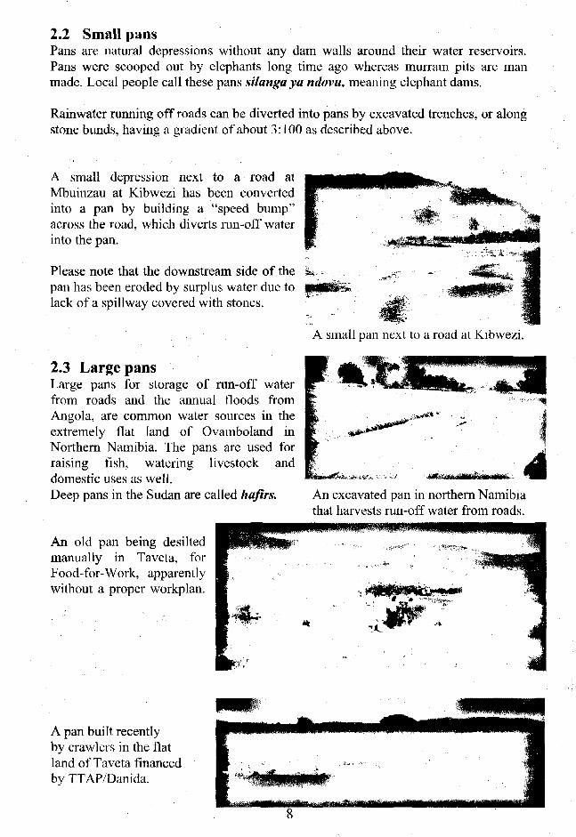
2.2 Small pansPans are natural depressions without any dam walls around their water reservoirs.Pans were scooped out by elephants long time ago whereas murrain pits are manmade. Local people call these pans silanga ya ndovu, meaning elephant dams.
Rainwater running off roads can be diverted into pans by excavated trenches, or alongstone bunds, having a gradient of about 3:100 as described above.
A small depression next to a road atMbuinzau at Kibwezi has been convertedinto a pan by building a "speed bump"across the road, which diverts run-off waterinto the pan.
Please note that the downstream side of thepan has been eroded by surplus water due tolack of a spillway covered with stones.
2.3 Large pansLarge pans for storage of run-off waterfrom roads and the annual floods fromAngola, are common water sources in theextremely flat land of Ovamboland inNorthern Namibia. The pans are used forraising fish, watering livestock anddomestic uses as well.Deep pans in the Sudan are called hafirs.
An old pan being desiltedmanually in Tavcta, forFood-for-Work, apparentlywithout a proper workplan.
A small pan next to a road at Kibwezi.
An excavated pan in northern Namibiathat harvests run-off water from roads.
A pan built recentlyby crawlers in the flatland of Taveta financedby TTAP/Damda.

2.4 PondsPonds are small earth dams that are made by scooping out soil and using the soil toconstruct a dam wall on the lower side of the water reservoir. There are three maintypes of small earth dams namely: Charco dams, hillside dams and valley dams.These dams are described in detail in another handbook of this series, namely Waterfrom Small Dams, and will therefore only be described briefly in this handbook.
2.5 Charco damsCharco dams are suitable where run-off from roads spill over onto flat land,preferably with silty or clayey soils. The best design for charco dams resembles acalabash cut in half for scooping and pouring water as shown in the photo below.
A calabash cut in half.
Plan and profiles of a charco dam A charco dam in Tanzania.
Charco dams and other small dams can be constructed in stages during dry seasons,when manual labour is available. Alternatively, neighbours who want to draw waterfrom somebody else's dam can be requested to scoop out and transport onewheelbarrow of soil for every jerrycan of water they want to carry home, or the watercan be sold for cash and used to hire contract labourers for deepening a dam.
At every stage, the water reservoir can be made deeper and the dam wall higher fromsoil excavated from the reservoir. This process can be continued until the dam canhold enough water throughout the year.
Cross sections of a charco dam showing the first and last stage of excavation works.
9

2.6 Hillside damsHillside dams are suitable where run-off water from roads can be diverted ontosloping land or hillsides. These dams have an oval-shaped water reservoir with asemi-circular dam wall on the lower side of the reservoir.
-A
A hillside dam at Lukcnya alongthe Nairobi - Mombasa highway.
Plan and profiles of a hillside dam.
Another hillside dam at Salamaon the same highway.
Hillside dams must have a spillway at eachend of the curved dam wall in order todischarge surplus water when the reservoiris full.
The two spillways should be at the samehorizontal level in order to discharge surpluswater safely. A horizontal line can be sightedalong the two water levels in a circular transparenthosepipe filled halfway with water.
Spillways must be reinforced with large stonesinterplanted with grass at the dam wall to prevent Sighting along the two water levels in aerosion by over-flowing water.
Also the floors of spillways should be coveredwith stones and grass and interplanted with typesof grass having many runners and long roots.
circular transparent hosepipe filledhalfway with water, gives an exacthorizontal line.
10
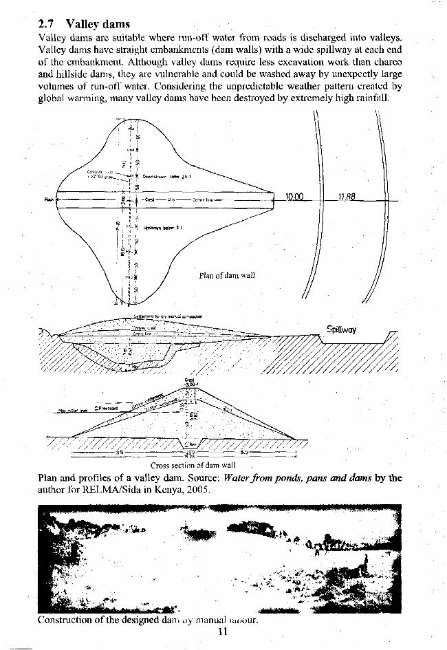
2.7 Valley damsValley dams are suitable where run-off water from roads is discharged into valleys.Valley dams have straight embankments (dam walls) with a wide spillway at each endof the embankment. Although valley dams require less excavation work than charcoand hillside dams, they are vulnerable and could be washed away by unexpectly largevolumes of run-off water. Considering the unpredictable weather pattern created byglobal wanning, many valley dams have been destroyed by extremely high rainfall.
Cross section of dam wall
Plan and profiles of a valley dam. Source: Water from ponds, pans and dams by theauthor for RELMA/Sida in Kenya, 2005.
Construction of the designed dam u> manual utoour.11

2.8 Tools and equipment for soil works
Plots having a volume of The "owners" of the plots excavate the soil and load it1 cubic metre of soil are onto wheelbarrows. Women transport the soil to the dampegged out and distributed, wall, off-load it and compact it manually.
1cu.m.
200 (2m)
300 (3'm)
400 K I T l )
leu rn.
10000 (tOm)
Various sizes of plots all with the same volume of 1 cubic metre of soil.
10mm iron rod
Side view
0.55
QiS
-090-
Tpp vit Bottom view Front vi»w
An ox-scoop made of 4 mm steel plate; with a plough and ox-scoop, two men and twooxen can excavate and transport more soil than 10 able-bodied men.
12

2.9 Analysis of soil samples
It is important to analyse samples of soil that shall be used for construction of dams inorder to minimise seepage losses. Naturally, the most clayey soil found on a dam siteshould be used for those parts of a dam wall that should be as impermeable aspossible. Sandy soils should be used on the downstream side of a dam wall whereweight, and not impermeability, is required.
A soil test that gives the percentage of clay, silt, sand and gravel can be carried out
A pinchof salt
1/3
;*
Water
J L
1/3
1/3
J\ .3cm of clay = 1 J _ = 20% clay6.5x100
• 17% silt1.1cm of silt = U
6.5x1002.3cm of sand = 2J _ = 35% sand
6~5x1001.8cm of gravel = 1.8
6.5x100
: 28% gravel
using a transparent bottle as follows:Fill a transparent bottle 1/3 with a soil sample and 1/3 with water. Add a pinch of salt.Shake the bottle vigorously for 1 minute. Leave it for 1 hour, then shake again. After4 hours, measure the thickness of each layer in the bottle. The upper layer is clayfollowed by silt, sand and gravel at the bottom. Find the percentage of each layer bymeasuring its thickness against the total thickness of the soil sample and multiply by100.
Another simpler but less accurate method is to remove the caps and bottoms of sometransparent plastic bottles. Fill the bottles halfway with soil and top up with water.Keep on adding water while watching the speed with which the water infiltrates thesoil.
\
vater j
SoilNo.1
I
: water;
Soil fi No.2
Bestsoil
• ;
i; water j
I
'*' SoilI No.3
I '• • I ' I. water ! water;r ji Soil...No,4.
f'Sbilfj!;No.5J
{••••• i
Poor soil
; water'
IPt":•Poil.:)
less seepage more seepage
Soil with the least infiltration has the highest clay content and is therefore the mostsuitable soil to use for the impermeable parts of a dam wall and its reservoir.Source: Water from ponds, pans and dams by the author,for RELMA/Sida in Kenya, 2005.
13

2.10 Construction costs of earth damsThe four types of earth dams listed below have different construction costs dependingon the construction method and the water-to-soil ratio.
a) The construction method relates to whether the excavation is done:1) Manually with shovels and wheelbarrows costing about Ksh 100/cu.m. soil.2) With draught animals, scoops, ploughs and carts, costing about Ksh 60/cu.m.3) Hiring a farm tractor with a plough and scoop costing about Ksh 80/cu.m.4) Hiring a crawler (bulldozer) costing about Ksh 300/cu.m. soil.
b) The water-to-soil ratio depends on the type of dam, because the volume of water:1) A pond is equal to the volume of excavated soil, therefore the ratio is 1:1.2) A charco dam is equal to the volume of soil, therefore also 1:1.3) A hillside dam is 1.5 times more than the excavated soil, therefore 1.5:1.4) A valley dam is 3 times more than the excavated soil, therefore 3:1.
Although valley dams have the lowest construction cost per m3 soil, because they canstore about 3 times more water than the excavated soil, they have a much higher rateof failure than other types of earth dams.
Type ofdam
Excava-ted pond
[Charcodams
1r •: ^
dams
LValleydams
Constructionmethod
Manual
Manual
TractorOxen
ManualTractorOxen
CrawlerManualTractorOxen
Reservoirvolumecu.m.
100
500
500500
500500
J.UOO
5,0005,0005,000
Waterto soilratio
1:1
i; 1
1:11:1
i.j.i
1.5:11.5:1
3:13:13:13:1
Excava- Cost Totalted soil per costcu.m. cu.m. Ksh.
100 x 100 = 10,000
500 x 100 = 50,000
500 x 80 = 40,000500 x 60 = 30,000
j i 3 x 100 33,300333 x 80 = 26,640333 x 60 = 19,980
1,6/0 x 300 -501,0001,670 x 100 =167,0001,670 x 80 =133,6001,670 x 60 =100,200
Cost percu.m. ofwaterstorageKsh.
100- " • ' «
loo]
8060
6<H5340 j
100332720
Source: Waterfront ponds, pans and dams by the author, for RELMA/Sida in Kenya, 2005.
2.11 References on earth damsDesign and Construction of Small Earth Dams. Nelson, K.D. Australia 1985.Field Engineering for Agricultural Development. Hudson, Oxford, UK.Small Earth Dam built by Animal Traction. Nissen-Petersen, E., Danida Kenya 1990.Small earth dams. Brown, L.N. University of California, USA 1965.Water from ponds, pans and dams. Nissen-Petersen, E. RELMA/Sida Kenya 2005.Water from Small Dams. Nissen-Petersen, E. Danida Kenya 2006.
14
Chapter 3. Water tanks
3.1 Advantages of water tanks.In regions with sandy soils, much water is usually lost from seepage in earth dams, andadditional water is also lost by evaporation due to the large surface area of the waterreservoirs. Furthermore, earth dams have other disadvantages such as siltation ofreservoirs due to lack of proper soil conservation, erosion by livestock watered in thereservoirs, water-borne diseases and vector carried diseases.
Since it is difficult and expensive to reduce these disadvantages of earth dams, it may bemore applicable to build water tanks. Although the capacity of water tanks is smaller thanearth dams, they have several advantages, such as:
1) Seepage can be eliminated by lining water tanks with clay, anthill soil, burntbricks, concrete blocks, ferro-cement or butyl rubber sheets.
2) Evaporation can be greatly reduced by roofing water tanks with live vegetation onwires, iron sheets, concrete covers or ferro-cement domes.
3) Siltation can be eliminated by excavating and regularly emptying silt traps.
4) Contamination by livestock and vectors can be avoided if the tanks are covered.
A number of well-functioning water tanks for harvesting rainwater run-off from roads aredescribed in the following pages. A common feature for all the tanks is that none of themhave a square or rectangular shape because these shapes always tend to crack.
Water tanks should always have a hemispherical or a cylindrical shape, because theseshapes distribute equally the external and internal pressures on the wall, therebyeliminating the risk of cracks due to uneven tension.
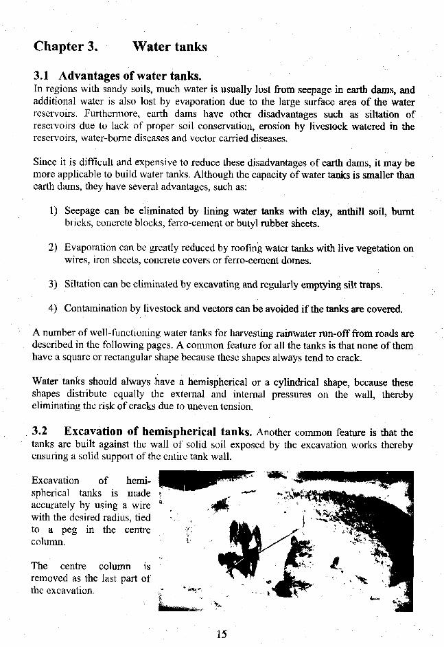
3.2 Excavation of hemispherical tanks. Another common feature is that thetanks are built against the wall of solid soil exposed by the excavation works therebyensuring a solid support of the entire tank wall.
Excavation of hemi-spherical tanks is madeaccurately by using a wire *with the desired radius, tiedto a peg in the centrecolumn.
The centre column isremoved as the last part ofthe excavation.
15

3.3 Hemispherical tank built of burnt bricks.Lay the first brick on its side inthe centre of the tank. Thereafterlay the following bricks on theirsides as a spiral winding theirway up towards the ground level.
For every metre or so, moistenthe bricks and compact mortarinto the spaces between thebricks, with a mixture of 1 partcement to 4 parts of coarse sand(1:4).
When the laying of bricks hasreached ground level, a centrepipe is erected and a radius wireis tied onto it for building thecircular foundation wall, whichprevents children and animalsfalling into the tank.
A silt trap built in front of theinlet. Two gaps are madeopposite each other to cater forthe inlet of rainwater and outletfor water overflowing the tank.
Barbed wire is then wrappedtightly in a spiral around theoutside of the tank wall aboveground level, with a spacing of10 cm.
Chicken mesh is thereafter nailedonto the inner wall of the tank foradditional reinforcement.
The internal and external wallsare then plastered with 1:4mortar and made water-proofwith NIL (cement slurry) the sameday.
16
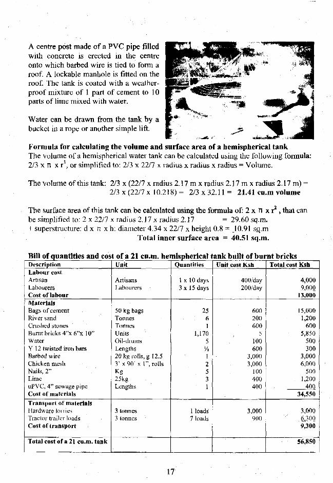
A centre post made of a PVC pipe filledwith concrete is erected in the centreonto which barbed wire is tied to form aroof A lockable manhole is fitted on theroof. The tank is coated with a weather-proof mixture of 1 part of cement to 10parts of lime mixed with water.
Water can be drawn from the tank by abucket in a rope or another simple lift.
Formula for calculating the volume and surface area of a hemispherical tankThe volume of a hemispherical water tank can be calculated using the following formula:2/3 x n x r3, or simplified to: 2/3 x 22/7 x radius x radius x radius = Volume.
The volume of this tank: 2/3 x (22/7 x radius 2.17 m x radius 2.17 m x radius 2.17 m) =2/3 x (22/7 x 10.218) = 2/3 x 32.11 = 21.41 cu.m volume
The surface area of this tank can be calculated using the formula of: 2 x n x r2 , that canbe simplified to: 2 x 22/7 x radius 2.17 x radius 2.17 = 29.60 sq.m.+ superstructure: d x n x h: diameter 4.34 x 22/7 x height 0.8 = 10.91 sq.m
Total inner surface area = 40.51 sq.m.
Bill of quantities and cost of a 21 cu.m. hemispherical tank built of burnt bricksDescriptionLabour costArtisanLabourersCost of labourMaterialsBags of cementRiver sandCrushed stonesBurnt bricks 4"x 6"x 10"WaterY 12 twisted iron barsBarbed wireChicken meshNails, 2"LimeuPVC, 4" sewage pipeCost of materialsTransport of materialsHardware lorriesTractor trailer loadsCost of transport
Total cost of a 21 cu.m. tank
Unit
ArtisansLabourers
50 kg bagsTonnesTonnesUnitsOil-drumsLengths20 kg rolls, g 12.53 'x90 ' x 1", rollsKg25kgLengths
3 tonnes3 tonnes
Quantities
1 x 10 days3 x 15 days
2561
1,1705Vi12531
1 loads7 loads
Unit cost Ksh
400/day200/day
600200600
5100600
3,0003,000
100400400
3,000900
Total cost Ksh
4,0009,000
13,000
15,0001,200
6005,850
500300
3,0006,000
5001,200
40034,550
3,0006,3009,300
56,850
17
4J30 (Internal Diameter)
Barbed wrapped outside andplastered (1:4) 20mm thick
J----S
Silt trap
Chicken wire nailed inside
and plaster (1:3) 30mm thick
150mni Burnt brick wall
„ A
PLAN (mm)
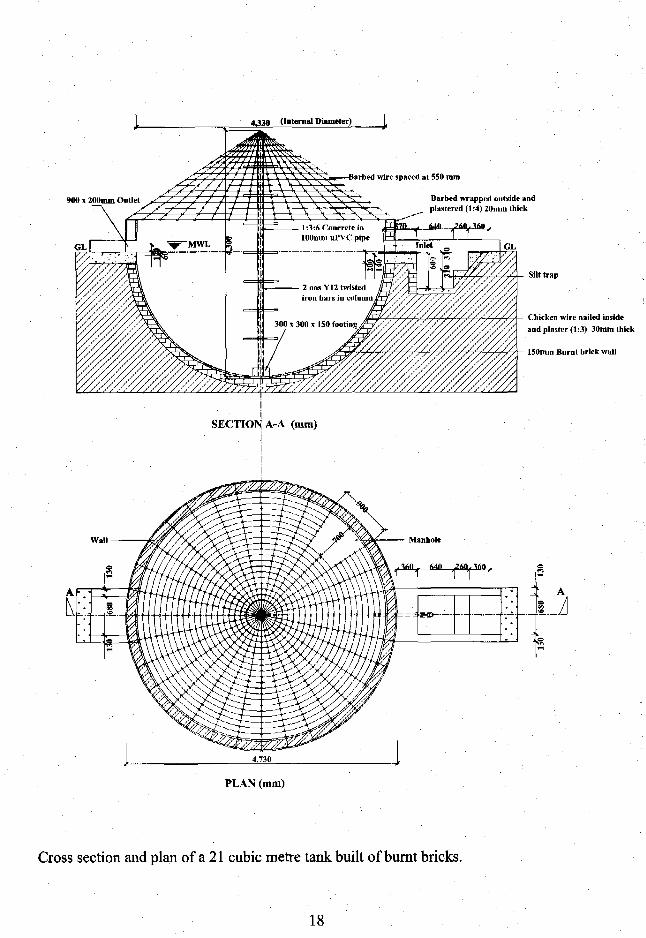
Cross section and plan of a 21 cubic metre tank built of burnt bricks.
18
3.4 Hemispherical tanks built of anthill soil, lime and cementAs seen above, the cost of building a water tank of burnt bricks with a storage volume of21.4 cum- is Ksh 56,850, equivalent to Ksh 2,656 er cubic metre storage volume.
The construction cost can be reduced by using powdered anthill soil as a part substitutefor cement and burnt bricks. The best of the two tanks described below has a storagevolume of 48 cu.m. and was constructed for Ksh 34,360, equivalent to Ksh 716 per cubicmetre storage volume. However, this saving of Ksh 1,940 per cu.m. as compared againstthe above brick tank, comes with a higher cost of maintenance and repair.
Nevertheless, it is an affordable tank to construct for most rural people. The cost ofmaintenance and repair can be recovered using the water for cash generating activities,such as growing and selling vegetables and tree seedlings, making and selling burntbricks, selling water, watering livestock, etc.
A dozen tanks were built of various mixtures of powdered anthill soil, lime, murram andcement 20 years ago by the author in Mutomo in Kitui District. A recent follow-up onthese tanks showed that some of the tanks are still performing well after two decadeseven despite lack of maintenance. Unfortunately, the records for the mixture ratios arelost and forgotten.
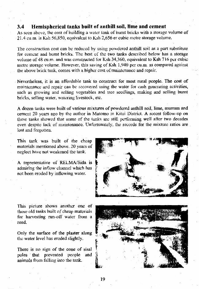
This tank was built of the cheapmaterials mentioned above. 20 years ofneglect have not weakened the tank.
A representative of RELMA/Sida isadmiring the inflow channel which hasnot been eroded by inflowing water.
This picture shows another one ofthose old tanks built of cheap materialsfor harvesting run-off water from aroad.
Only the surface of the plaster alongthe water level has eroded slightly.
There is no sign of the cone of sisalpoles that prevented people andanimals from falling into the tank.
19

Two water tanks were built of anthill soil, lime, sand and cement during a training courseat Makaani Primary School at Kibwezi in 1998.
1) The tanks were excavated using a radius wire that was 290 cm long and theirvolume was calculated as follows:
2) The radius of each tank: 290 cm minus 6 cm of plaster = 284 cm radius
3) The volume of each water tank was calculated using the formula of:2/3 x n x r3 simplified to: 2/3 x (22/7 x radius x radius x radius) = Volume.
4) The volume of this tank: 2/3 x (22/7 x radius 2.84 m x radius 2.84 m x radius2.84 m) = 2/3 x (22/7 x 22.91) = 2/3x72.00= 48.00 cu.m volume
5) The surface area of this tank can be calculated using the formula of: 2 x n x r2
that can be simplified to: 2 x 22/7 x radius 2.84 x radius 2.84 = 50.70 sq.m.plus superstructure: d x n x h = 5.68x 22/7 x height 0.8 = 14.28 sq.m
Total inner surface area 64.98 sq.m.
Two types of plasterAnthills were broken into particles that could pass through a sieve made of coffee mesh.
a) The 6 cm plaster for one tankwas made of:4 parts anthill soil1 part cement2 parts lime6 parts river sand
b) The 6 cm plaster for the othertank was made of:
| 20 parts anthill soil2 parts cement1 part lime18 parts river sand
A woman sieving anthill soil.
The 6 cm thick plaster was reinforced with chicken mesh nailed to the first coat of 3 cmplaster. After 14 days of curing the plaster was coated with bitumen paint.
A visit to the tanks three years later showed that the plaster mixture (a) above was themost superior, although the inflow of water had eroded part of the plaster due to acomplete lack of maintenance by the school, its pupils and parents.
20

lOOmin ul'YC pipe withconcrete (1:2:4) anil 2 IIIY12 irunbsrs
PLAN (mm)
Cross section and plan of 48 cu.m. water tank built of anthill soil, lime, sand and cement
21
Bill of quantities and cost of the best 48 cu.m. tank built of anthill soil, lime, etc.
DescriptionAnthill soilCementLimeCrushed stonesRiver sandBurnt bricksChicken meshBarbed wirePVC pipeIron barsNailsWaterArtisanLabourersTotal
UnitTonnes50 kg bags25 kg bagsTonnesTonnesNumbers3f t .x90f t .x l"20 kg rolls, g 12.53 metres of 4"3 metres of Yl25 kg of 2"7 oil drums1 artisan3 labourers
Quantity75317
3003 rollsIroll
1 length1/2 length
10 days15 days
Unit cost Ksh300600300600200
53,0003,000
400600100100400200
Total cost Ksh2,1003,000
900600
1,4001,5009,0003,000
400300500700
4,0009,000
36,400
The first ground tanks for harvesting rainwater from roads and compounds were roofedwith corrugated iron sheets tied onto galvanized iron pipes in 1983. Since goats and cattlecould smell the water, they walked on the roofs and damaged them.
The iron sheet roofs were therefore replaced by sisal poles arranged in a pyre and heldtogether with an old tyre at the top. Passion fruit and lupher plants were grown on barbedwire wrapped around the sisal poles.
22
3.5 Hemispherical tanks built of ferro-cementSome 100 hemispherical water tanks with a storage volume of 60 cu.m, and 90 cu.m.were built of ferro-cement for roof and ground catchments by the Danida funded MuiomoSoil & Water Conservation Project in Kitui in the 1980s.
The ferro-cement tanks are still in good shape but the roofs, made of corrugated ironsheets nailed onto timber, collapsed after some years. The collapsed roofs could easilyand cost-effectively be replaced with domes made of ferro-cement, but no-one has takenon this responsibility.
A USATD Peace Corps Volunteer replicated and enlarged the volume these hemisphericaltanks in many places in Kenya. Many of these larger than normal tanks have crackedbecause the usual the reinforcement of barbed wire and chicken mesh is insufficient whenthe storage volume exceeds 100 cu.m. Some of these large tanks have been rehabilitatedby building a new tank inside the damaged ones.
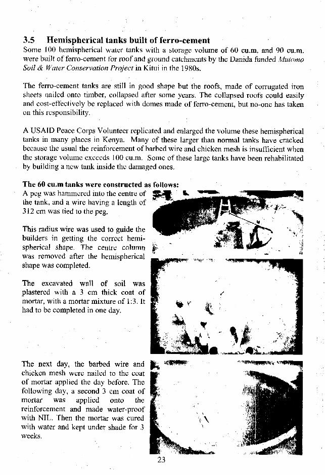
The 60 cu.m tanks were constructed as follows:A peg was hammered into the centre ofthe tank, and a wire having a length of312 cm was tied to the peg.
This radius wire was used to guide thebuilders in getting the correct hemi-spherical shape. The centre columnwas removed after the hemisphericalshape was completed.
The excavated wall of soil wasplastered with a 3 cm thick coat ofmortar, with a mortar mixture of 1:3. Ithad to be completed in one day.
The next day, the barbed wire andchicken mesh were nailed to the coatof mortar applied the day before. Thefollowing day, a second 3 cm coat ofmortar was applied onto thereinforcement and made water-proofwith NIL. Then the mortar was curedwith water and kept under shade for 3weeks.
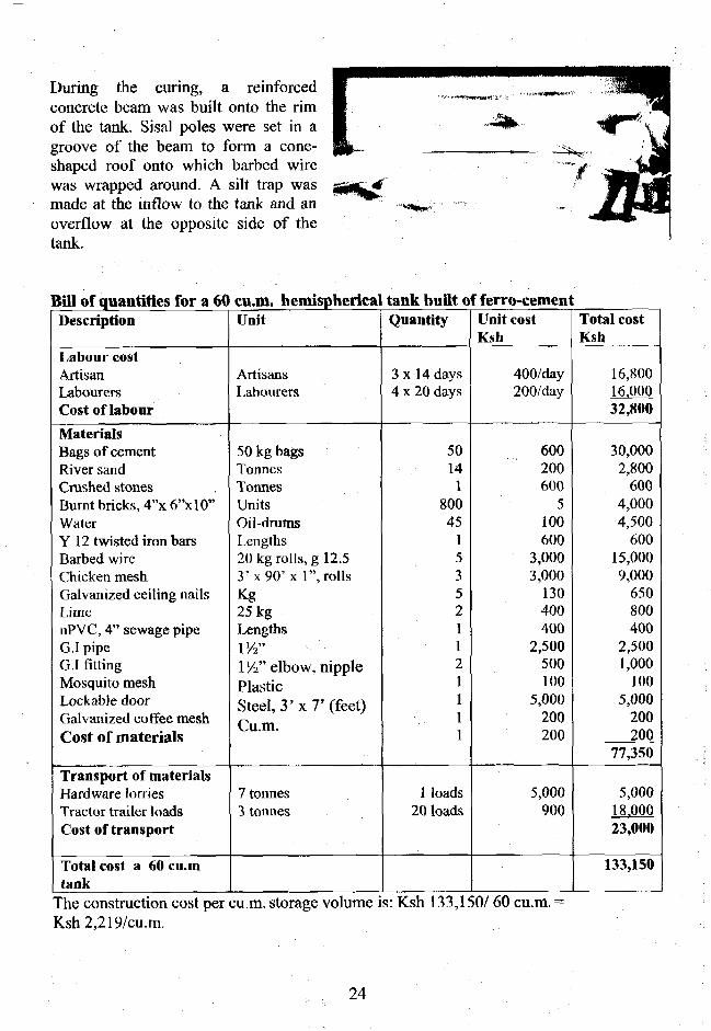
During the curing, a reinforcedconcrete beam was built onto the rimof the tank. Sisal poles were set in agroove of the beam to form a cone-shaped roof onto which barbed wirewas wrapped around. A silt trap wasmade at the inflow to the tank and anoverflow at the opposite side of thetank.
Bill of quantities for a 60Description
Labour costArtisanLabourersCost of labour
MaterialsBags of cementRiver sandCrushed stones .Burnt bricks, 4"x6"x 10"WaterY 12 twisted iron barsBarbed wireChicken meshGalvanized ceiling nailsLimeuPVC, 4" sewage pipeG.I pipeG.I fittingMosquito meshLockable doorGalvanized coffee meshCost of materials
Transport of materialsHardware lorriesTractor trailer loadsCost of transport
Total cost a 60 cu.mtank
cu.m. hemisphericalUnit
ArtisansLabourers
50 kg bagsTonnesTonnesUnitsOil-drumsLengths20 kg rolls, g 12.53 'x90 'x 1", rollsKg25 kgLengthsVA"1 Vi" elbow, nipplePlasticSteel, 3' x 7' (feet)Pn mV^U.lll.
7 tonnes3 tonnes
tank built of ferro-cementQuantity
3x 14 days4 x 20 days
5014
180045
153521121111
1 loads20 loads
Unit costKsh
400/day200/day
600200600
5100600
3,0003,000
130400400
2,500500100
5,000200200
5,000900
Total costKsh
16,80016.00032,800
30,0002,800
6004,0004,500
60015,0009,000
650800400
2,5001,000
1005,000
200200
77,350
5,00018.00023,000
133,150
The construction cost per cu.m. storage volume is: Ksh 133,150/ 60 cu.m. =Ksh2,219/cu.m.
24

•A
A :\
1 J
/
1
PLAN
Standard design of a 60 cu.m. hemispherical water tank built of ferro-cement.
In order to avoid hand pumps which require maintenance and spare parts occasionally,this design features a staircase leading down to a watertap from which water can bedrawn by gravity from the tank.
An additional advantage is that the staircase is also functions as a water reservoir. Whensurplus water is overflowing, it spills over onto the staircase. Water is drawn from thestaircase by opening the steel door covering it and lifting a bucket of water out of thestaircase.
25

3.6 Cylindrical underground water tanks
Cylindrical tanks have been used formany years to harvest and storerainwater running off threshing floorsfrom the sparse rains in the semi-desertareas of Botswana.
Water is drawn with a bucket from themanhole on the cover of the tank asillustrated in this photo.
A sketch showing the catchment area,which could have been a road as well,and the underground cylindrical tankbuilt of burnt bricks.
This type of cylindrical ground tank isused in the hot and arid NorthernNamibia to store water for constructionof schools.
These tanks are also very suitable forcollecting rainwater run-off fromroads.
These two cylindrical ground tankswere built of soil compressed blocksfor fish farming at Machakos in Kenyain 1980s. The tanks could also havebeen used for harvesting rainwaterfrom roads.
Cemented or treated-earth catchment
Cemented or corrugatediron cover
*£-%£* — Inflow through stoneand sand filter

•*•*><
This muK was initially bum for storage of water for construction uuimy a uaiinn^, muise atKibwezi in Kenya in 1997. Upon completion of the training, the tank was equipped witha silt trap and used for harvesting water from a road.
This gigantic cylindrical ground tank was constructed for harvesting rainwater from alarge concrete apron near Dodoma in Tanzania in 1992. The tank could also have beenused as road catchment of rainwater.
27

3.7 BerkadsBerkads are tanks that are excavatedand lined with concrete blocks orferro-cement in the semi-desert regionsof Somaliland. Rainwater running offroads and hillsides is diverted into theberkads by soil bunds sloping upwardson hillsides until they reach a road.
Most berkads have rectangular shapeswith vertical walls that crack due touneven external pressure of the soilwhen the berkads dry up.
Water is drawn from berkads by eitherusing the steps or the band-dug wellseen in the upper photo.
This handbook promotes the muchstronger oval-shaped berkads that has ashape as the silt trap in this photo.
A newly made soil bund winds its waydownwards though the bush from anunpaved road on a hillside.
Walking down hill in the bund, anewly built berkad is reached at theend of the bund.
The bund guides the run-off water intothe silt trap before it enters the berkad.
The excavated soil has been back-filled against the berkad. This couldfacilitate siphoning of water downhillfor watering livestock or small-scaleirrigation.
28
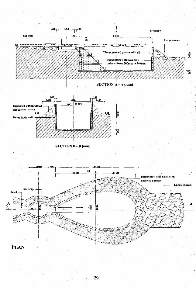
Overflow
Silt trapT—5"
20mm internal plaster with nil _ ;
Burnt brick wall thicknessreduced from 200mm to 140mm
SECTION A - A (mm)
Ml), „14*11
Excavated soil backfilled , ,--•
against the herkad iA
Burnt brick wall
_1 _ffj• • I M W L
I4^n
SECTION B - B (mm)
J9S0 ,750 W44II
Excavated soil backfilcdagainst berkad
Large stones
PLAN
29

A2366.
innn mnn . innnjono
PLAN OF EXCAVATION
Marking a berkad on the ground can be made as follows:
1) Mark the highest place of the site for the inlet with a wooden peg.
2) Mark the lowest place of the site for the overflow with a peg situated 13m fromthe inlet.
3) Draw a 13 m long nylon string between the two pegs. The string represents thecentre line, called A-A, on the plan seen above.
4) Then place 14 pegs along the centre line with the intervals shown in centimetresbelow. The length of the berkad is 12766 mm = 1276.6 cm = 12.766 m = 12.77 m.
5) Starting from peg No. I at the inlet and measuring towards peg No. 14 (listed inthe upper row) the measurements between the pegs are listed as cm in the middlerow.
6) The figures in the lowest row are the distances from the centre line to the edge ofthe excavation. Use a long mason's square to mark these measurements at anangle of 90 degrees to the centre line.
153103
210087
310032
410075
510036
610040
7100125
8100172
9100207
10100228
11100237
12100232
13100203
1424109
Total1277
30
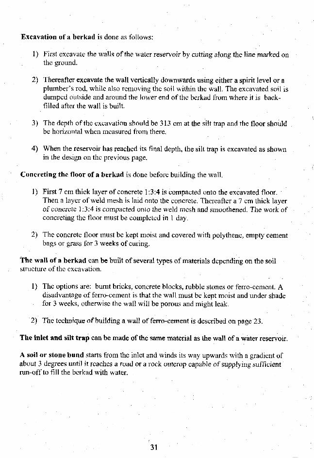
Excavation of a berkad is done as follows:
1) First excavate the walls of the water reservoir by cutting along the line marked onthe ground.
2) Thereafter excavate the wall vertically downwards using either a spirit level or aplumber's rod, while also removing the soil within the wall. The excavated soil isdumped outside and around the lower end of the berkad from where it is back-filled after the wall is built.
3) The depth of the excavation should be 313 cm at the silt trap and the floor shouldbe horizontal when measured from there.
4) When the reservoir has reached its final depth, the silt trap is excavated as shownin the design on the previous page.
Concreting the floor of a berkad is done before building the wall.
1) First 7 cm thick layer of concrete 1:3:4 is compacted onto the excavated floor.Then a layer of weld mesh is laid onto the concrete. Thereafter a 7 cm thick layerof concrete 1:3:4 is compacted onto the weld mesh and smoothened. The work ofconcreting the floor must be completed in 1 day.
2) The concrete floor must be kept moist and covered with polythene, empty cementbags or grass for 3 weeks of curing.
The wall of a berkad can be built of several types of materials depending on the soilstructure of the excavation.
1) The options are: burnt bricks, concrete blocks, rubble stones or ferro-cement. Adisadvantage of ferro-cement is that the wall must be kept moist and under shadefor 3 weeks, otherwise the wall will be porous and might leak.
2) The technique of building a wall of ferro-cement is described on page 23.
The inlet and silt trap can be made of the same material as the wall of a water reservoir.
A soil or stone bund starts from the inlet and winds its way upwards with a gradient ofabout 3 degrees until it reaches a road or a rock outcrop capable of supplying sufficientrun-off to fill the berkad with water.
31
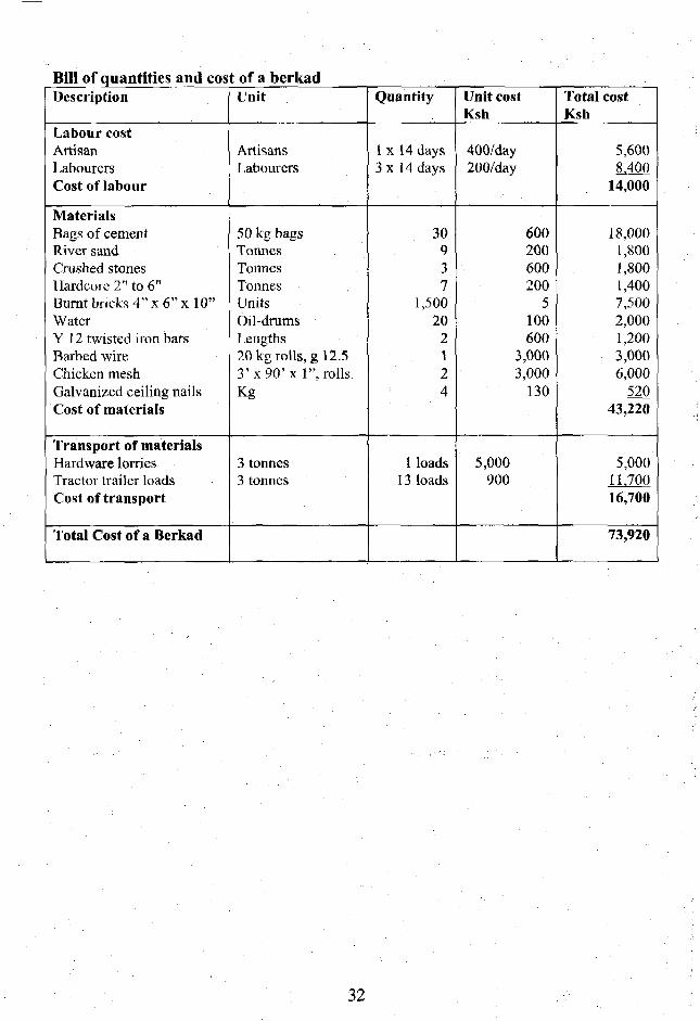
Bill of quantities and cost of a berkadDescription
Labour costArtisanLabourersCost of labour
MaterialsBags of cementRiver sandCrushed stonesHardcore 2" to 6"Burnt bricks 4" x 6" x 10"WaterY 12 twisted iron barsBarbed wireChicken meshGalvanized ceiling nailsCost of materials
Transport of materialsHardware lorriesTractor trailer loadsCost of transport
Total Cost of a Berkad
Unit
ArtisansLabourers
50 kg bagsTonnesTonnesTonnesUnitsOil-drumsLengths20 kg rolls, g 12.53 'x90 'x 1", rollsKg
3 tonnes3 tonnes
Quantity
1 x 14 days3x14 days
30937
1,50020
2124
1 loads13 loads
Unit costKsh
400/day200/day
600200600200
5100600
3,0003,000
130
5,000900
Total costKsh
5,600*L400
14,000
18,0001,8001,8001,4007,5002,0001,2003,0006,000
52043,220
5,00011.70016,700
73,920
32
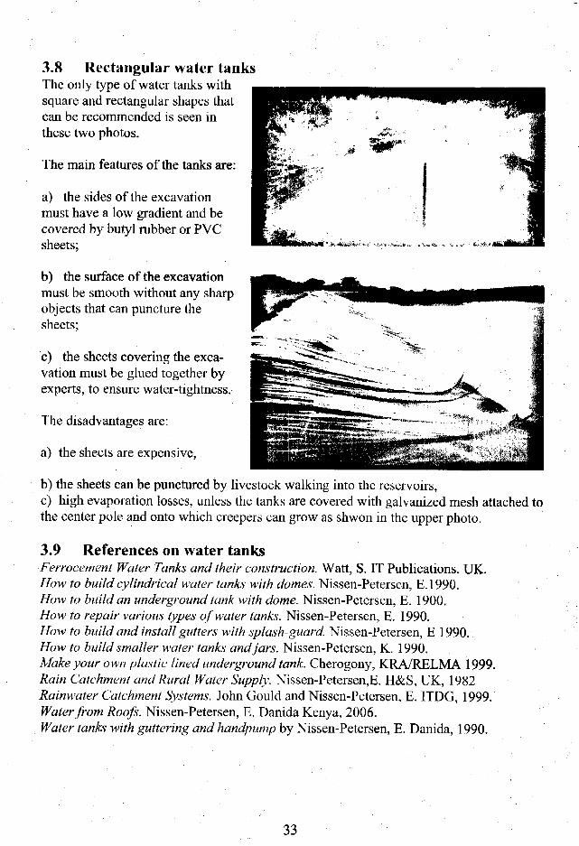
3.8 Rectangular water tanksThe only type of water tanks withsquare and rectangular shapes thatcan be recommended is seen inthese two photos.
The main features of the tanks are:
a) the sides of the excavationmust have a low gradient and becovered by butyl rubber or PVCsheets;
b) the surface of the excavationmust be smooth without any sharpobjects that can puncture thesheets;
c) the sheets covering the exca-vation must be glued together byexperts, to ensure water-tightness.
The disadvantages are:
a) the sheets are expensive,
b) the sheets can be punctured by livestock walking into the reservoirs,c) high evaporation losses, unless the tanks are covered with galvanized mesh attached tothe center pole and onto which creepers can grow as shwon in the upper photo.
3.9 References on water tanksFerrocement Water Tanks and their construction. Watt, S. IT Publications. UK.How to build cylindrical water tanks with domes. Nissen-Petersen, E. 1990.How to build an underground lank with dome. Nissen-Petersen, E. 1900.How to repair various types of water tanks. Nissen-Petersen, E. 1990.How to build and install gutters with splash-guard. Nissen-Petersen, E 1990.How to build smaller water tanks and jars. Nissen-Petersen, K. 1990.Make your own plastic lined underground tank. Cherogony, KRA/RELMA 1999.Rain Catchment and Rural Water Supply. Nissen-Petersen,E. H&S, UK, 1982Rainwater Catchment Systems. John Gould and Nissen-Petersen, E. ITDG, 1999.Waterfront Roofs. Nissen-Petersen, E, Danida Kenya, 2006.Water tanks with guttering and handpump by Nissen-Petersen, E. Danida, 1990.
33
Chapter 4. Subsurface dams
Most rainwater running off roads passes through gullies and riverbeds on its way tothe sea. Some of that water can be trapped in one, or several, of the types ofsubsurface dams that are described briefly in this chapter and in detail in anotherhandbook of this series: Waterfront Dry Riverbeds.
4.1 Water in sand reservoirsThe main feature of subsurface dams is that their water reservoir is full of sand, wherewater is stored in the voids between the sand particles. 350 litres of water (35%) canbe extracted from 1 cu.m. (1,000 litres) of coarse sand, due to its large voids. Fine-textured sand provides less than 190 litres (19%) of water from 1 cu.m. of sand, whileonly 50 litres (5%) of water may be extracted from silt due to its tiny voids.Subsurface reservoirs should therefore always contain as much coarse sand aspossible. Storing of water in sand reservoirs has the following advantages:
1) Evaporation loss is minimal: Evaporation decreases proportionally with thewater's distance to the sand surface, and it is reduced to zero at a depth of 60cm below the surface of the sand.
2) The water is not contaminated by large numbers of animals, because the wateris 'hidden' below the surface of the sand. Some contamination does occur bypassing animals etc, but it is limited to the area close to the sand surface, andno contamination occurs at the depth where the water is extracted.
3) Mosquitoes and other disease-spreading insects, as well as frogs and snakes,cannot live in water stored in sand reservoirs.
Many gullies and riverbeds contain only fine-textured sand particles or no sand at all.In such cases, coarse sand can be trapped from floodwater by means of constructing asand dam as explained in the next pages.
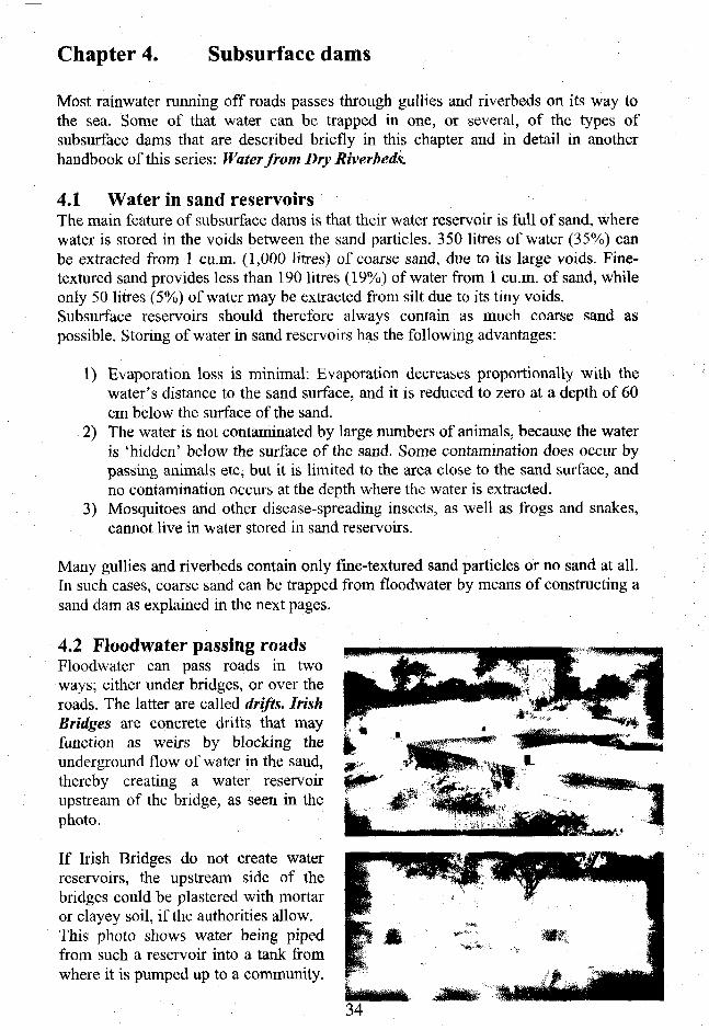
4.2 Floodwater passing roadsFloodwater can pass roads in twoways; either under bridges, or over theroads. The latter are called drifts. IrishBridges are concrete drifts that mayfunction as weirs by blocking theunderground flow of water in the sand,thereby creating a water reservoirupstream of the bridge, as seen in thephoto.
If Irish Bridges do not create waterreservoirs, the upstream side of thebridges could be plastered with mortaror clayey soil, if the authorities allow.This photo shows water being pipedfrom such a reservoir into a tank fromwhere it is pumped up to a community.

4.2 Hand-dug wellsHand-dug wells are the easiest and cheapest structures for the extraction of waterfrom riverbeds containing sand. Wells can either be placed directly in a riverbed witha well-head protected against flood damage, or in a riverbank. The latter may requirea perforated pipe to drain water from the riverbed into the well.
It is always important to sink a hand-dug well in, or at, the deepest part of a riverbed,because that gives access to the most water. Such deep places can be identified byeither:
1) Trees, such as wild figs and other trees that can only grow where water isavailable all year round.
2) Water holes excavated by people or animals that yield water for some timeor throughout dry seasons.
3) Dowsing by gifted persons walking along riverbeds in dry seasons.
4) Probing by hammering long and retrievable iron rods into the sand ofriverbeds. This technique can produce hydraulic profiles that show thecorrect places to sink wells and boreholes, and to construct weirs andsubsurface dams as shown below.
f F- t ? f 1 P 1 ? r f - j - 4 - MFlood
*r.$ s-3f-$-$ i 5
ila 2^ 200 1*0 1J0 lit) ijo 1A0 8C 60 40 20 J M «) 60 slo 100120 llo l ieU O m
This longitudinal profile of a riverbed was drawn from measurements taken fromprobing with an iron rod at 20 metres intervals. The most suitable place for sinking awell is between probing number 2 and 4 on the left side of the profile because here theriverbed is deepest and will therefore provide most water.
Hand-dug wells can be built in two waysdepending on their depths. Shallow wellscan be excavated to their final depth andthen built from the bottom and upwards withburned bricks as shown in this photo.
35
Tf hand-dug wells have to be sunk in deep sand, the"sinking" method should be used, because it is safeand economical.
The well-shaft is made of curved concrete blocksthat are reinforced together, atop a concretefoundation ring which is made in a circular groovecut into the sand of the well site. The concreteblocks are then mortared and tied with GI wiresonto the foundation ring with steps built in the wallfor easy entry and exit. When sand is scooped outof the shaft, it sinks into the sand. More blocks arethen added and scooping repeated, and so on untilthe shaft has sunk to its final depth.
Concrete culverts can also be used for sinking shafts but they are difficult to handle.
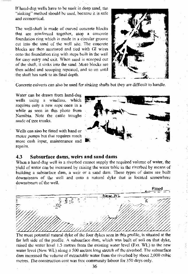
Water can be drawn from hand-dugwells using a windlass, whichrequires only a new rope once in awhile as seen in this photo fromNamibia. Note the cattle troughsmade of tree trunks.
Wells can also be fitted with hand ormotor pumps but that requires muchmore cash input, maintenance andrepairs.
4.3 Subsurface dams, weirs and sand damsWhen a hand-dug well in a riverbed cannot supply the required volume of water, theyield of water can be increased by raising the water table in the riverbed by means ofbuilding a subsurface dam, a weir or a sand dam. These types of dams are builtdownstream of the well and onto a natural dyke that is located somewheredownstream of the well.
Flood
The most potential natural dyke of the four dykes seen in this profile, is situated at thefar left side of the profile. A subsurface dam, which was built of soil on that dyke,raised the water level 1.5 metres from the existing water level (Ext. WL) to the newwater level (New WL) along a 500 metres long stretch of the riverbed. The subsurfacedam increased the volume of extractable water from the riverbed by about 2,000 cubicmetres. The construction cost was free community labour for 350 days only.
36

4.4 Subsurface dams, whose walls are built of soilSubsurface dam walls built of soil consist of replacing the sand laying on an under-ground dyke with soil taken from the riverbanks. The dam wall made of soil preventsfloodwatcr from infiltrating in the sand and seeping downstream in the riverbed. Thetrapped water can be extracted from a hand-dug well sunk into the deepest part of theriverbed.
7^-~> Hydro-dynamic well-head •
A longitudinal profile of a riverbed combined with a three dimensional view of asubsurface dam, whose wall of soil is built onto a natural dyke, and a hand-dug wellsunk into the deepest part of the riverbed.
J
Depth of 600
CROSS SECTION B-B
Standard design and profiles of a subsurface dam built of soil.37

Construction of subsurface dams whose walls are built of soil:
The base for the wall is cleared byremoving all sand from the site in astretch of about 2 metres wider than thebase of the wall.
The width of the base is marked ontothe riverbed and excavated to a depthof 20 cm into the floor of clayey soil orlatcrite.
The profile of the dam wall is markedonto the riverbanks.
A key, 60 cm wide, is then excavatedalong the centre of the base and intothe banks to a depth of at least 60 cm.Should layers of sand be found in thekey, it must be deepened to 60 cmbelow any layer of sand.
The dam wall is constructed of themost clayey soil found near the site.First the soil is compacted into the key,preferably with water. Then the wall isconstructed, layer-by-layer, each 20 cmthick, of soil that is well compacted.
The upstream and downstream sidesare cut to 45 degrees slope andsmoothened. If the soil found forbuilding the key and dam wall islacking in clay content, the upstream
side of the dam wall should be plastered with a layer of clay or soil mixed with dungfor the purpose of making it more water proof. When the dam wall is completed, theexcavated sand is back-filled.
&;;
tbterS6ilNo.1
SoilNo. U
WaterSoilNo, 5
Soil can be analysed in transparent plastic bottles without bottoms and caps. Placethe bottles upside down in sand and fill the bottles halfway with soil samples andtop up with water. The soil with the slowest seepage, seen in Soil No. 3, is the bestfor building dam walls, because it has the highest clay content.
38
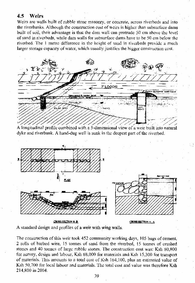
4.5 WeirsWeirs are walls built of rubble stone masonry, or concrete, across riverbeds and intothe riverbanks. Although the construction cost of weirs is higher than subsurface damsbuilt of soil, their advantage is that the dam wall can protrude 50 cm above the levelof sand in riverbeds, while dam walls for subsurface dams have to be 50 cm below theriverbed. The 1 metre difference in the height of sand in riverbeds provide a muchlarger storage capacity of water, which usually justifies the bigger construction cost.
THZZZZZA
A longitudinal profile combined with a 3-dimensional view of a weir built into naturaldyke and riverbank. A hand-dug well is sunk in the deepest part of the riverbed.
B i ,
PLAN
'/////////////ACROSS SECTION B- 8 citoassEcnoNA-A
A standard design and profiles of a weir with wing walls.
The construction of this weir took 452 community working days, 105 bags of cement,2 rolls of barbed wire, 15 tonnes of sand from the riverbed, 15 tonnes of crushedstones and 40 tonnes of large rubble stones. The construction cost was: Ksh 80,800for survey, design and labour, Ksh 68,000 for materials and Ksh 15,300 for transportof materials. This amounts to a total cost of Ksh 164,100, plus an estimated value ofKsh 50,700 for local labour and materials. The total cost and value was therefore Ksh214,800 in 2004.
39

Construction of a weir consists of the following procedure:
Remove the sand in a 2 metres widestretch across the riverbed.
Excavate the key to be 60 cm wide and100 cm below any layer of sand found inthe soil of the riverbed and riverbanks.
The height of the wing walls above theriverbanks can be 60 cm only.
Wash rubble stones and compact them intoa 20 cm high layer of mortar mixture of 1cement to 4 sand, which is laid in thebottom of the key along its whole length.
Then lay 4 lengths of thick barbed wire inthe key along its whole length forreinforcement of the dam wall. Continuelaying 20 cm layers of mortar andcompacting rubble stones into it.
Another 4 lengths thick barbed wire arelaid into the mortar at 20 cm intervalsbefore the final height of the wall.
The wall is built to 50 cm above the levelof sand in the riverbed by applying mortar
to flat rubble stones along the outer sides of the wall. Next day the space between thesides are filled with mortar and rubble stones.
4.6 Sand damsSand dams are structures that can raise the level ofsand and water to several metres height far upstreamof the dam wall. Sand dams are much morecomplicated to design and construct than subsurfacedams and weirs, because of the pressure made byfloods and the elevated sand and water that pressagainst the dam wall.
As a matter of fact, most sand dams do not functionwell and many have been washed away by floods.However, one design has proved more successful thanall the others and that is the ALDEV (African LandDevelopment) design from the 1950s. The designcriteria is based on the height of the spillway asshown on this sketch.
40
"'k'. ̂ . h x O . 5 5 ' ' . .••'/:•,
— : — h x O . 7 5 - — -•*
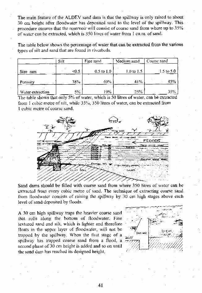
The main feature of the ALDEV sand dam is that the spillway is only raised to about30 cm height after floodwater has deposited sand to the level of the spillway. Thisprocedure ensures that the reservoir will consist of coarse sand from where up to 35%of water can be extracted, which is 350 litres of water from 1 cu.m. of sand.
The table below shows the percentage of water that can be extracted from the varioustypes of silt and sand that are found in riverbeds.
Size mm
Porosity
Water extraction
Silt
<0.5
38%
5%
Fine sand
0.5 to 1.0
40%
19%
Medium sand
1.0 to 1.5
4 1 %
25%
Coarse sand
1.5 to 5.0
45%
35%
The table shows that only 5% of water, which is 50 litres of water, can be extractedfrom 1 cubic metre of silt, while 35%, 350 litres of water, can be extracted from1 cubic metre of coarse sand.
Sand dams should be filled with coarse sand from where 350 litres of water can beextracted from every cubic metre of sand. The technique of extracting coarse sandfrom floodwater consists of raising the spillway by 30 cm high stages above eachlevel of sand deposited by floods.
A 30 cm high spillway traps the heavier coarse sandthat rolls along the bottom of floodwater. Finetextured sand and silt, which is lighter and thereforefloats in the upper layer of floodwater, will not betrapped by the spillway. When the first stage of aspillway has trapped coarse sand from a flood, asecond phase of 30 cm height is added and so on untilthe sand dam has reached its designed height.
W////A
41
SECTION B-B
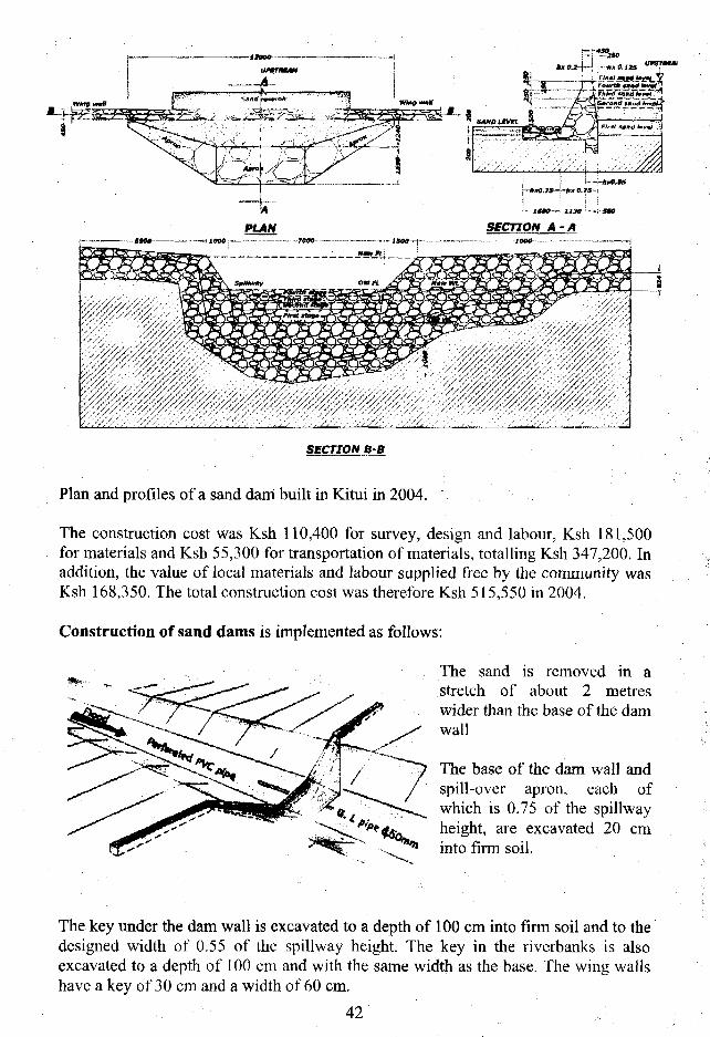
Plan and profiles of a sand dam built in Kitui in 2004.
The construction cost was Ksh 110,400 for survey, design and labour, Ksh 181,500for materials and Ksh 55,300 for transportation of materials, totalling Ksh 347,200. Inaddition, the value of local materials and labour supplied free by the community wasKsh 168,350. The total construction cost was therefore Ksh 515,550 in 2004.
Construction of sand dams is implemented as follows:
The sand is removed in astretch of about 2 metreswider than the base of the damwall
The base of the dam wall andspill-over apron, each ofwhich is 0.75 of the spillwayheight, are excavated 20 cminto firm soil.
The key under the dam wall is excavated to a depth of 100 cm into firm soil and to thedesigned width of 0.55 of the spillway height. The key in the rivcrbanks is alsoexcavated to a depth of 100 cm and with the same width as the base. The wing wallshave a key of 30 cm and a width of 60 cm.
42 : :
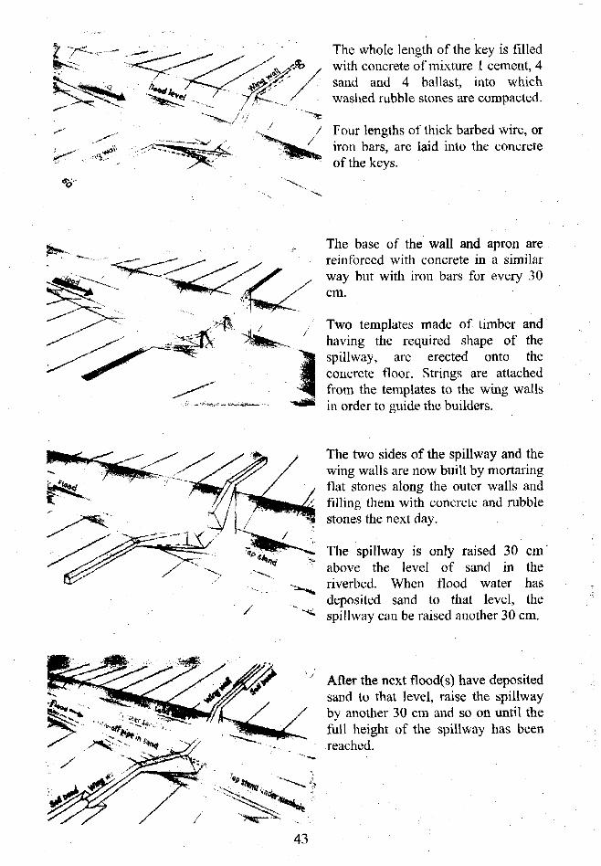
The whole length of the key is filledwith concrete of mixture 1 cement, 4sand and 4 ballast, into whichwashed rubble stones are compacted.
Four lengths of thick barbed wire, oriron bars, are laid into the concreteof the keys.
The base of the wall and apron arereinforced with concrete in a similarway but with iron bars for every 30cm.
Two templates made of timber andhaving the required shape of thespillway, are erected onto theconcrete floor. Strings are attachedfrom the templates to the wing wallsin order to guide the builders.
The two sides of the spillway and thewing walls are now built by mortaringflat stones along the outer walls andfilling them with concrete and rubblestones the next day.
The spillway is only raised 30 cmabove the level of sand in theriverbed. When flood water hasdeposited sand to that level, thespillway can be raised another 30 cm.
After the next flood(s) have depositedsand to that level, raise the spillwayby another 30 cm and so on until thefull height of the spillway has beenreached.
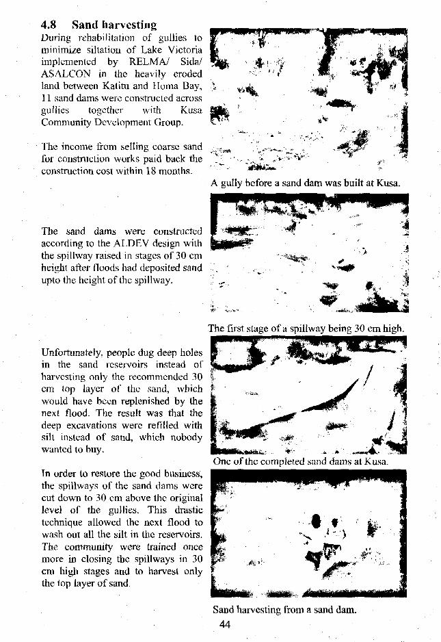
4.8 Sand harvestingDuring rehabilitation of gullies tominimize siltation of Lake Victoriaimplemented by RELMA/ Sida/ASALCON in the heavily erodedland between Katitu and Homa Bay,11 sand dams were constructed acrossgullies together with KusaCommunity Development Group.
The income from selling coarse sandfor construction works paid back theconstruction cost within 18 months.
The sand dams were constructedaccording to the ALDEV design withthe spillway raised in stages of 30 cmheight after floods had deposited sandupto the height of the spillway.
A gully before a sand dam was built at Kusa.
The first stage of a spillway being 30 cm high.
Unfortunately, people dug deep holesin the sand reservoirs instead ofharvesting only the recommended 30cm top layer of the sand, whichwould have been replenished by thenext flood. The result was that thedeep excavations were refilled withsilt instead of sand, which nobodywanted to buy.
Tn order to restore the good business,the spillways of the sand dams werecut down to 30 cm above the originallevel of the gullies. This drastictechnique allowed the next flood towash out all the silt in the reservoirs.The community were trained oncemore in closing the spillways in 30cm high stages and to harvest onlythe lop layer of sand.
One of the completed sand dams at Kusa.
Sand harvesting from a sand dam.44

4.9 Gold and gemstones from sand damsUNDP and ASALCONtrained engineers andtechnicians to survey,design and constructsubsurface dams, weirsand sand dams in the DryZone of Burma in 1994.During a follow-up visit tothe dams in 1995, peoplewere washing gold out ofthe sand dam.
Tn Eastern Kenya, rubiesare found in sand damsnear a volcanic hill. Gold being washed out of a sand dam in Burma.
In Western Kenya, sand bags were placed across streams and gold was found justupstream of the barriers.
The explanation for these additional benefits of sand dams, is that gold and gemstones are heavier than the other materials that floodwater transports downstream inriverbeds. When floodwater passes over the almost level surface of the reservoirs ofsand dams, the velocity of the flowing water is reduced with the heaviest material,such as gold and gemstones settle down into the sand of these dams.
4.10 References on subsurface dams, weirs and sand damsDying Wisdom.CentYe Agarwal, A, and Narain, S. 1991 for Science and Environment, India.Groundwater arresting subsurface structures. Ahnfors, O. 1980. Sida/ Govt. of India.Sand storage dams for water conservation. Burger, S.W.I 970. Water Year 1070. S. Africa.Water Quality Data Book. Faillace, C. and E.R. 1987. Water Development Agency, Somalia.The feasibility of Sand Dams in Turkana. Fewstcr, E. 1999. Loughborough University, UK.Underground dams in arid zone riverbeds. Finkel & Finkel Ltd. 1978. Haifa, Israel.Underground water storage in Iran. Finkel & Finkel Ltd. 1978. Haifa. Israel.Rainwater Catchment Systems. Gould, J. and Nissen-Petersen, E.1999. IT Publications, UK.Field Engineering for agricultural development. Hudson, N.W. 1975. Oxford, UK.Field Engineering. Longland, F. 1938. Tanganyika.Storage of groundwater behind subsurface dam. Newcomb, R.C. 1961. US Geol.Survey. USGroundwater Dams for small-scale water supply. Nilsson, A. 1988. IT Publications. UK.Rain Catchment and Water Supply in Rural Africa. Nissen-Petersen, E. 1982H & S, UK.Subsurface dams and sand dams. Nissen-Petersen, H. and Lee, M. 1990. Danida Kenya.Subsurface and Sand-storage Dams. Nissen-Petersen, E. 1995. UNDP/Africare, Tanzania.Harvesting rainwater in semi-arid Africa. Nissen-Petersen, E. 1990. Danida, Kenya.Ground Water Dams in Sand-rivers. Nissen-Petersen, E. 1996. UNCHS, Myanmar.Water from Sand Rivers, Nissen-Petersen, E. 2000. RBLMA/Sida, Kenya.Water from Dry Riverbeds, Nissen-Petersen, E. 2006. Danida, Kenya.Where there is no water. Mutiso, G. and Thomas, D. 2000. SASOL, Kenya.Subsurface dams and its advantages Raju, K.C.B. 1983..Ground Water Board, India.Ephemeral rivers in the tropics, Sandstrom, K. 1997. Linkoping University, Sweden.Sub-surface dams Slichter. 1902..USGS Water Supply and Irrigation. USA.The storage of water in sand. Wipplinger, O. 1958. Water Affairs, South West Africa.Sand storage dams in South-West Africa. Wipplinger, O. 1974. South Africa.
45
Chapter 5. Run-off farming
5.1 Drainage from roads by engineers
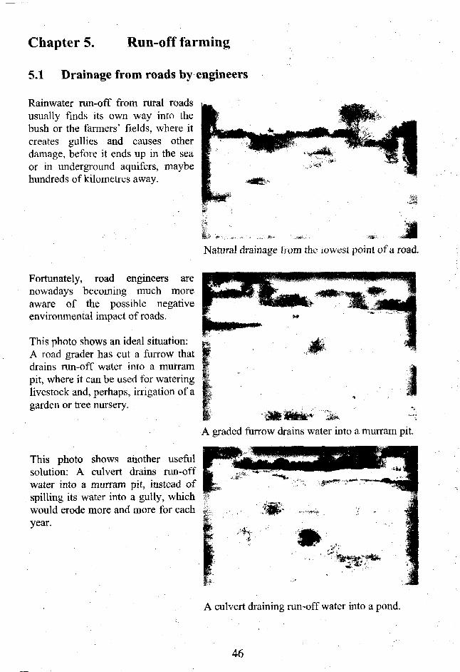
Rainwater run-off from rural roadsusually finds its own way into thebush or the farmers' fields, where itcreates gullies and causes otherdamage, before it ends up in the seaor in underground aquifers, maybehundreds of kilometres away.
Natural drainage from the lowest point of a road.
Fortunately, road engineers arenowadays becoming much moreaware of the possible negativeenvironmental impact of roads.
This photo shows an ideal situation:A road grader has cut a furrow thatdrains run-off water into a murrampit, where it can be used for wateringlivestock and, perhaps, irrigation of agarden or tree nursery.
A graded furrow drains water into a murram pit.
This photo shows another usefulsolution: A culvert drains run-offwater into a murram pit, instead ofspilling its water into a gully, whichwould erode more and more for eachyear.
A culvert draining run-off water into a pond.
46
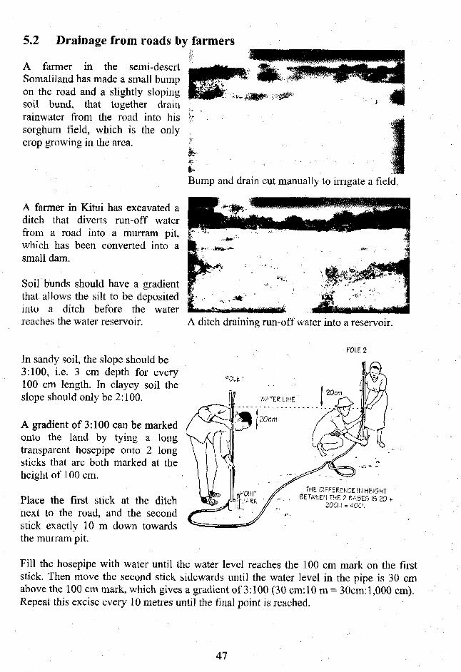
5.2 Drainage from roads by farmers
A fanner in the semi-desertSomaliland has made a small bumpon the road and a slightly slopingsoil bund, that together drainrainwater from the road into hissorghum field, which is the onlycrop growing in the area.
Bump and drain cut manually to irrigate a field.
A farmer in Kitui has excavated aditch that diverts run-off waterfrom a road into a murrain pit,which has been converted into asmall dam.
Soil bunds should have a gradientthat allows the silt to be depositedinto a ditch before the waterreaches the water reservoir. A ditch draining run-off water into a reservoir.
. POLE 2
In sandy soil, the slope should be3:100, i.e. 3 cm depth for every100 cm length. In clayey soil theslope should only be 2:100.
A gradient of 3:100 can be markedonto the land by tying a longtransparent hosepipe onto 2 longsticks that are both marked at theheight of 100 cm.
Place the first stick at the ditchnext to the road, and the secondstick exactly 10 m down towardsthe murram pit.
Fill the hosepipe with water until the water level reaches the 100 cm mark on the firststick. Then move the second stick sidewards until the water level in the pipe is 30 cmabove the 100 cm mark, which gives a gradient of 3:100 (30 cm:10 m = 30cm:l,000 cm).Repeat this excise every 10 metres until the final point is reached.
THE DIFFERENCE IN HEIGHTBETWEEN THE 2 BASES 15 2 0 -
20CI.I = 4OCU
47
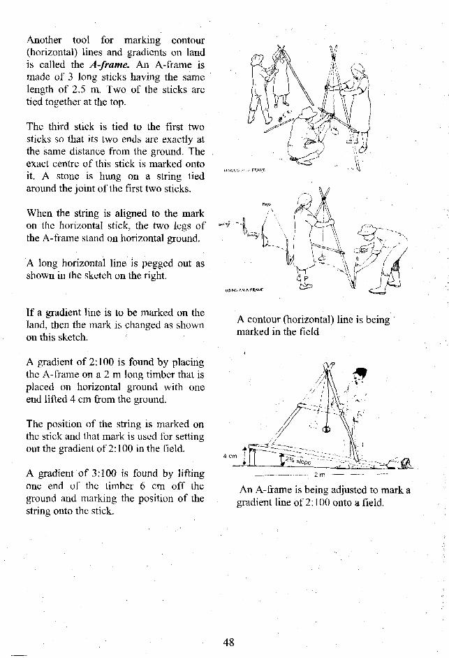
Another tool for marking contour(horizontal) lines and gradients on landis called the A-frame. An A-frame ismade of 3 long sticks having the samelength of 2.5 m. Two of the sticks aretied together at the top.
The third stick is tied to the first twosticks so that its two ends are exactly atthe same distance from the ground. Theexact centre of this stick is marked ontoit. A stone is hung on a string tiedaround the joint of the first two sticks.
When the string is aligned to the markon the horizontal stick, the two legs ofthe A-frame stand on horizontal ground.
A long horizontal line is pegged out asshown in the sketch on the right.
If a gradient line is to be marked on theland, then the mark is changed as shownon this sketch.
A gradient of 2:100 is found by placingthe A-frame on a 2 m long timber that isplaced on horizontal ground with oneend lifted 4 cm from the ground.
The position of the string is marked onthe stick and that mark is used for settingout the gradient of 2:100 in the field.
A gradient of 3:100 is found by liftingone end of the timber 6 cm off theground and marking the position of thestring onto the stick.
A contour (horizontal) line is beingmarked in the field
III i__ /o s'°Pe— •••- 2 m
An A-frame is being adjusted to mark agradient line of 2:100 onto a field.
48

A third method of setting out contourlines consists of tying a spirit level tothe middle of a string with each endtied onto 2 sticks of exactly sameheight and spaced 10m apart.
When the air-bubble in the spirit ^ ^ C ' i v i \level is exactly in the middle, the S^jji^isticks are then standing on horizontalground. Three farmers are setting out a horizontal line.
If a gradient of 3:100 is to be marked, then the 10 m long string is tied 30 cm lower thanthe other stick. For a gradient of 2:100, the string on one stick must be 20 cm lower thanon the other stick.
A fourth method is tosight along two waterlevels in a circulartransparent hosepipethat is half filled with ?water.
XA#L£Two tanners are using circular transparent hosepipes filledhalfway with water to sight horizontal lines.
To find two horizontal points, oneperson sights along the two waterlevels in the pipe towards anotherperson with the same eye height,while this person moves up or downuntil their eyes are at the same level. Distance approximately 10m
To mark a gradient of 3:100, measure 30 cm down from the other person's eyes and markthe point at his/her clothes. Then the two persons hold a 10 m long string between themwhile the first person sights towards the point marked on the second person who movesup or down until the two water levels align with the marked point on the second person.When that point is reached, the gradient is 3:100 on that 10 m stretch.
49

5.3 Soil bunds
Soil bunds are used for transporting run-off water from a catchment area, such asa road, into either a murram pit, an earthdam or a ground tank or for seasonalirrigation of fields.
Fruit trees and bananas can be grown inthe bottom of soil bunds, while foddergrasses and multi-purpose scrubs andtrees can be planted on the banks ofexcavated soil.
In this photo, the soil bund has to becleaned of banana debris before it candivert run-off water to the far end of thefield where it is needed for seasonalirrigation.
Bananas and papaya growing in a soil bund,while sisal and kei apple mark the boundaryby growing on the downstream bank.
Bananas growing a soil bund.
Soil bunds can also be made on steep land if thevelocity of run-off water is slowed by means oflarge stones placed across the soil bunds. Suchbarriers are called check dams.
It is advisable to plant creeping grass between thestones of check dams because it "concretes" thestones together as seen in the photo.
50

5.4 Gullies
Rainwater running off catchments,such as roads, starts as sheet erosionthat might enlarge to become rillerosion, which might develop intogullies.
Gully erosion causes much damageto fields and should therefore alwaysbe stopped at an early stage bymeans of check dams.
A simple check dam can be made by placing large stones across a shallow gully as seenin this photo from Somaliland. However, the wing walls were not high enough, andfloodwater has "eaten" away parts of the two banks and has by-passed the check dam.
The check dam seen in this photo from Dodoma, Tanzania is made correctly. The twowing walls are high above the spillway in the centre of the check dam and floodwaterpasses over the spillway while depositing silt and soil in the gully upstream of the checkdam.
This sketch showsa series of checkdams correctlybuilt of squarestones or blockslaid across a longgully.
checkdam sediment•_.—~̂ penetrating accumulates
.->JCl-£=--;£ into gully wall behind dam
stone step tobreak fall ofwaterspilling
over dam
<£->••
51
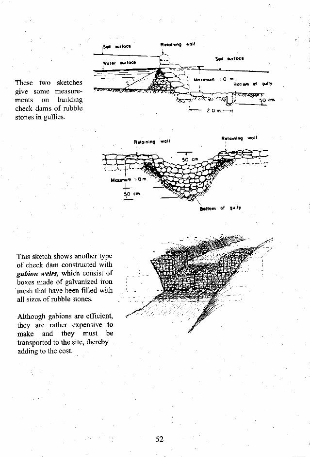
,S«i mttac*
These two sketchesgive some measure-ments on buildingcheck dams of rubblestones in gullies.
cm.
Rttamloq woll
Bottom ol
This sketch shows another typeof check dam constructed withgabion weirs, which consist ofboxes made of galvanized ironmesh that have been filled withall sizes of rubble stones.
Although gabions are efficient,they are rather expensive tomake and they must betransported to the site, therebyadding to the cost.
52

Plastic bags filled with soil andstones are much more affordablethan gabions.
This check dam made of sand bagsand a spillway excavated into oneof the two banks was built in adeep gully near Lake Victoria. Thefirst flash flood had just passed.Silt and water arc deposited in thegully, while surplus water wasdi scharged over the spi 11 way.
After a few flash floods more,grass has "concreted" the sandbags into a dam wall. The gully isalmost filled with fertile silt andgreen vegetation is growing on thebanks of the former gully.
Nearby another farmer built asimple sand dam across a deepgully. The main purpose of thedam is to harvest sand for sale. Asecondary purpose is to protect hisfarm land being consumed by thegully.
Another 10 sand dams were builtin the area for sand harvesting andgully control. The construction costof these dams was recovered byselling sand for 18 months only.
A check dam made of sand bags in a deep gully.
After a few rain showers the gully is healed.
53

Another type of check dam is the masonryweir. Weirs are constructed of eitherconcrete or rubble stone masonry.
The main purpose of this weir seen in thephoto was to provide water for the DreamCamp, now the Base Camp at the TalckRiver running along the Masai Mara GamePark, Kenya.
An additional advantage of the improvedwater supply was that the vegetation turnedso lush upstream of the weir that birds,hippos and crocodiles settled down there.
To improve the environment even more,which attracts tourists and environmentalists,weir was enlarged to become a sand
The weir built across the Taiek River.
An aerial photo taken in October 2006 of thesand dam built over the weir in the TalekRiver shows the difference made to theenvironment.
The vegetation is green, large and lushupstream of the sand dam (upper centre ofthe photo) while there is very littlevegetation downstream of the sand dam(lower centre and left side of the photo).
% • -
An aerial view of the sand dam in TalekRiver in October 2006.
Most dry riverbeds and gullies could be turned into good water sources and that wouldimprove the environment by the simple means of check dams, subsurface dams, masonryweirs and sand dams described above.
54

5.5 Macro-irrigation
Roads are excellent catchment areas. Due to their hard surface, 1 km of a narrow 4 metrewide road can produce about 1,000 cubic metres of water from a rainfall of 300 mm only.
This large volume of water can be used productively instead of the damage it is doing tofields, gullies, riverbeds, rivers and the sea itself where the siltation destroys bathing andfishing areas and the coral reefs.
The following macro-irrigation schemes are based on the techniques that were used in theNcgev Desert in Israel some 3,000 years ago. Some of the macro-irrigation systems,which have been replicated at Kibwezi, Baringo and a few other arid and semi-arid placesin Eastern Kenya, are presented briefly in this section. More detailed information can befound in the References in this handbook.
This sketch shows howrun-off water from a roadwas diverted into a valleyat Kibwezi for thepurpose of providingdomestic water andgrowing fruit trees, crops,etc.
A series of stone and soilbunds were built acrossthe valley. Each bund hada spillway to allowsurplus water to spill overinto the next bundwithout causing erosion.
Hand-dug wells sunkbetween and below thebunds supply water forgarden irrigation anddomestic water duringdry seasons.
wall
After Ihe first year, an alluvialdeposit, shaped more or lesslike a triangle, forms above eachcontour bund. These depositsretain moisture longer thanadjacent land.
55
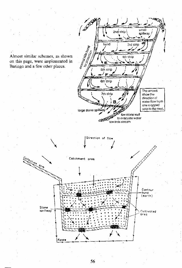
Almost similar schemes, as shownon this page, were implemented inBaringo and a few other places.
large stone spillway
The arrowsshow thedirection ofwaterflowfromone croppedstrip to the next.
low stone wallto evacuate water
towards stream
Direction of flow
Contourbund( e a r t h )
Cultivatedarea
56

5.6 References on run-off farming
Dying Wisdom. Anil Agarwal and Sunita Narain. CSE, India 2003.Land and Life. . Hugues Dupriez. Philip DeLenener. Macmillan Publisher, U.K.Looking after our land. Will Critchley.Oxfam, U.K. 1991.Managing land. Technical Handbook No. 36. RELMA/Sida. 2005.Production without Destruction. H.L. Vukasin, L.Roos, N. Spicer. M. Davies. ZimbabweSoil Conservation in Arusha Region, Tanzania.The Negev. Michael Evenari. Leslie Shanan, Naphtali Tadmor. Harvard University USA.Vanishing Land and Water. Jean-Louis Chleq. Hugues Dupriez. Macmillan Pub. U.K.Ways of Water. Hugues Dupriez. Philip DeLenener. Macmillan Publisher, U.K.
57


![Hemispherical Resonator Gyro [Akimov; $MP-043-06]](https://img.dokumen.tips/doc/110x75/5527500b550346e1358b47b0/hemispherical-resonator-gyro-akimov-mp-043-06.jpg)