Embed Size (px)
Citation preview

www.lge.com
OPERATION & MAINTENANCE MANUAL
Water-Cooled Centrifugal ChillerPlease read this installation manual completely for safety before installing the product.The purpose of this manual is to keep the user safe and to prevent anyproperty damage. After reading this installation manual, please retain it for futurereference thoroughly Installation work must be performed in accordance with thisinstallation manual by authorized personnel only.
Model : RCWF***P(200~3000RT)
ENGLIS
H
P/NO : MFL68929303 (Rev 0)

ENG
LISH
2
For your recordsStaple your receipt to this page in case you need it to prove the date of purchase or for warranty purposes. Write the model number and the serial number here:
Model number :
Serial number :
You can find them on a label on the side of each unit.
Dealer’s name :
Date of purchase :

ENG
LISH
1. CAUTIONS FOR SAFETY _ WARNING/CAUTION 3
1. CAUTIONS FOR SAFETY _ WARNING/CAUTIONIt can be dangerous when moving, installing and placing the system for its high pressure, electricdevices and heavy weight especially when lifting the unit in a limited space(rooftop, lifted struc-ture, etc.). Please read carefully the warnings and cautions on this manual and the labels attached on theunit, and follow the instructions.Please follow the following instructions to prevent any injury or property damage• It may result in an injury or damages when neglecting the instructions on in this manual.
The seriousness of the result can be classified as the following signs.• Please note that any failure of system resulted by user’s careless maintenance, natural disaster
or the failure of the power cable shall not be warranted regardless of the warranty period.• Please note that any part of this manual can be revised without notice for the product improve-
ment.
WARNINGIt can result in serious injury or death when the directions are ignored.
CAUTIONIt can result in minor injury or product damage when the directions are ignored.
The meanings of the symbols used in this manual are as follows.
This is the symbol to call attention for the issues and operations that may cause danger.To prevent the occurrence of the danger, read carefully and follow the instructions.This is the symbol showing the how-to-use instruction in order to prevent danger.
Follow the direction.
1-1. WARNING• Have all electric work done by a licensed electrician according to "Electric Facility Engineering Standard" and "Interior
Wire Regulations" and the instructions given in this manual and always use a special circuit.
- If the power source capacity is inadequate or electric work is performed improperly, electric shock or fire may re-sult.
• Ask the dealer or an authorized technician to install the chiller unit.
- Improper installation by the user may result in water leakage, electric shock, or fire.
• For re-installation of the installed product, always contact a dealer or an Authorized Service Center.
- There is risk of fire, electric shock, explosion, or injury.
• Make sure to equip the circuit breaker and fuse.
- Improper wiring or installation may cause fire or electric shock.
• Do not disassemble, repair or reconfigure the unit.
- LG Electronics is not responsible for the any damage or loss from the arbitrary disassembly, repair or reconfigura-tion of the unit.
• Make sure to ground the unit properly.
- There is risk of fire or electric shock.
• Do not store or use flammable gas or combustibles near the chiller unit
- There is risk of fire or failure of product.
• Do not reconstruct to change the settings of the protection devices.
- If the pressure switch, thermal switch, or other protection device is shorted and operated forcibly, or parts otherthan those specified by LGE are used, fire or explosion may result.
• Install the unit on a foundation where the heavy weight can be supported.
- Insufficient strength of the foundation to support the chiller operation may cause the unit failure or injury.
!
!
!

ENG
LISH
4 1. CAUTIONS FOR SAFETY _ WARNING/CAUTION
• Installing the product in small space requires separate measures to keep the leakage of the refrigerant within thesafety limits in case of any leakage.
- Consult the authorized dealer for appropriate measures to prevent the refrigerant leakage from exceeding thesafety limits. The leakage of refrigerant exceeding the safety limit may result in dangerous situations due to thelack of oxygen level in the room.
• Securely install the cover of control box and the panel.
- If the cover and panel are not installed securely, dust or water may enter the unit and fire or electric shock may re-sult.
• Do not operate the unit arbitrarily.
- Incorrect operation of the unit may cause dangerous situations such as unit defects, leakage or electric shock. Al-ways consult the authorized dealer.
• Do not use damaged circuit breaker or fuse works correctly all the time.
- It may cause fire, electric shock or injury.
• Keep the control panel from any water getting in.
- Do not wash the control panel with water. It can cause electric shock or defects.
• When the product is soaked (flooded or submerged), contact an Authorized Service Center.
- There is risk of fire or electric shock.
• Use a dedicated outlet for this unit.
- There is risk of fire or electric shock.
• Make sure to charge only the exclusive refrigerant R134a when installing or moving to other place.
- If a different refrigerant or air is mixed with the original refrigerant, the refrigerant cycle may malfunction and theunit may be damaged.
• Do not touch the power switch with wet hands.
- There is risk of fire, electric shock, explosion, or injury.
• Ventilate before operating the chiller unit when gas leaked out.
- Do not use a phone or operate the power switch at this time. It may cause fire or explosion.
• Do not put any heavy object on the top of the unit or climb on the unit.
- It may cause defects or injury.
• Be careful with the rotating part.
- Do not put your fingers or a stick to the rotating part. It can cause injury.
• Use the fuse and circuit breaker with rated capacity.
- It may cause fire and defects.
• Redesigning the control box is prohibited.
- Lock the control box with possible locking device and if you need to open the control box inevitably, turn off themain power first.
• Do not touch the wiring or a parts inside the panel.
- It may cause electric shock, fire or defects.
• Follow the permitted pressure level
- Follow the regulated pressure for cold water, cooling water, refrigerant etc.
• Do not change the set values.
- Do not change the set values of the controller and safety devices. Operating with inappropriate setting can causedamages. When changing the setting values, please consult with the specialist.
• Be careful of fire, earthquake and lightening.
- In case of any natural disaster such as fire, earthquake or lightening, immediately stop operating the unit. If youcontinue to operate the unit, it can cause a fire or electronic shock.
• Follow all safety code.
- When operate the chiller, follow the precautions on the manual, tag, sticker and label.
• Use of undesignated refrigerant and oil is prohibited.
- Do not use undesignated refrigerant, freezer oil and brine. It may cause serious effect to the compressor andparts defect.
• During the installation and service, shut down the power supply.
- Electric shock can cause injury and death. Mark and check all switches so that the power is not recovered untilthe work is completed.

ENG
LISH
1. CAUTIONS FOR SAFETY _ WARNING/CAUTION 5
• Wear safety equipment
- Wear safety glasses and work gloves. Be careful when installing or operating the chiller and operating the electri-cal components.
• Always run fluid through heat exchangers when adding or removing refrigerant charge.
- Potential damage of the tube within the heat exchanger can be prevented. Use Appropriate brine solution incooler fluid loops to prevent the freezing of heat exchangers when equipment is exposed to temperature below0°C.
• Do not vent refrigerant relief valves within a building.
- Outlet from relief valves must be vented outdoors in accordance with the latest edition of ANSI/ASHRAE(Ameri-can National Standards Institute/American Society of Heating, Refrigeration and Air Conditioning Engineers) 15(Safety Code for Mechanical Refrigeration). The accumulation of refrigerant in an enclosed space can displaceoxygen and cause asphyxiation. Provide adequate ventilation in enclosed or low overhead areas. Inhalation of highconcentrations of refrigerant gas is harmful and may cause heart irregularities, unconsciousness or death. Misusecan be critical. Refrigerant gas is heavier than air and reduces the level of oxygen. It can cause irritation to eyesand skin.
• Be careful of water leakage.
- In case of any water leakage in the pump or pipe, immediately stop operating the unit. It may cause electricshock, electricity leakage or defects. Be careful of electric shock.
• Always ground the chiller during installation.
- It may cause electric shock.
• Do not leave refrigerant system open to air any longer than necessary.
- If the repair cannot be completed, seal the circuits to prevent any contamination or rust within the product, andcharge dry nitrogen.
• Do not reuse compressor oil.
- It can damage the product.
• During installation, make the specified grounding before supplying the power, and during the dismantling, removethe grounding line at the end of the task.
• Use appropriate meters for measurement. Otherwise, it may cause injury or electric shock.
• Check all power connected to the control panel or starter panel to be shut off while applying the power.
- It may cause electric shock.
• Make sure to discharge the electric current before inspection or repair work.
- It may cause injury or electric shock.
• Do not open the 2nd phase side of the current transformer when power is on.
- High voltage could be discharged causing an electric shock.
• Remove foreign objects(working tools, wires, bolts, washers) after installation, inspection, and repair work.
- They may cause injury, fire, or damage.
• When using a condenser, make sure to verify the complete discharge before applying the power again. (Re-power-ing within 5 min. is prohibited.)
- It may cause electric shock, fire, damage, or malfunction.
• Change the condenser in case that the expansion exceeds the recommended limit.
- It may cause electric shock, fire, damage, or malfunction.

ENG
LISH
6 1. CAUTIONS FOR SAFETY _ WARNING/CAUTION
1-2. CAUTIONOperation & Maintenance• Always check for gas(refrigerant) leakage after installation or repair of product.
- Low refrigerant levels may cause failure of product.
• Do not install the unit where combustible gas may leak.
- There is risk of fire or failure of product
• Keep level even when installing the product.
- Unleveled refrigerant can cause problems to the product.
• Do not use the product for special usage or location such as preserving animal/plant, precision machine, artifact,etc.
- It may cause property damage.
• Use exclusive wire for the product. Use power cables of sufficient current carring capacity and rating.
- It may cause fire and electric shock.
• When installing the unit in a hospital, communication station, or similar place, provide sufficient protection againstnoise.
- The inverter equipment, private power generator, high-frequency medical equipment, or radio communicationequipment may cause the chiller to operate erroneously, or fail to operate. On the other hand, the chiller may af-fect such equipment by creating noise that disturbs medical treatment or image broadcasting.
• To protect the product from corrosion, do not install the product where it is exposed to sea wind(salt spray) directly.If necessary, please install shield.
- It may cause product deformation and defects.
• Make the connections securely so that the outside force of the cable may not be applied to the terminals.
- Inadequate connection and fastening may generate heat and cause fire. If the power cable got damaged, do notdirectly replace it, but call the service center for replacement first.
• Do not use the product in special environments.
- Oil, steam and sulfuric steam can deteriorate the product performance or cause damage to the parts.
• Be careful when transporting the product.
- When carrying the chiller, always consult with the specialized expert.
• When transporting the chiller, always follow the methods described in the manual.
- If not, it can cause overturn, fall etc.
• Do not touch any of the refrigerant piping during and after operation.
- Pipe during and after the operation can be hot or cold depending on the condition of the refrigerant flowingthrough the refrigerant pipe, compressor and refrigerant cycle parts.Touching the pipes at this time can cause burns or frostbites.
• Turn on the main power 12 hours before starting to operate the product.
- If you operate the product immediately after turning on the main power, it can severely damage the internal parts.Keep the main power on while operating.
• Do not immediately turn off the main power after the product stops operating.
- Wait at least 5 minutes before turning off the main power. Failure to do so can cause water leak or other issues.
• Do not operate the product with the panel or safety devices removed.
- Rotating parts or high temperature/pressure parts can cause safety accidents.
• Be careful when disposing the product.
- When disposing the chiller, request to the specialized expert.
• Use a firm stool or ladder when cleaning or maintaining the chiller.
- It may cause an injury.
• Be careful of high temperature.
- Be careful not to make body contact to the parts of the chiller in high temperature.It may cause a burn.
• Be careful of high voltage.
- Install separate wiring for the power and always install and use dedicated power supply and circuit breaker.It can cause electric shock and fire.

ENG
LISH
1. CAUTIONS FOR SAFETY _ WARNING/CAUTION 7
• Be careful of chiller installation.
- Keep enough clearance around the product for service and especially for air cooling type, install the product at wellventilated location where there is no obstacle.
• Harsh chemical, household bleach or acid cleaner should not used to clean outdoor or indoor coils of any kind.
- These cleaners can be very difficult to rinse out of the coil and can accelerate corrosion at the fin/tube interfacewhere dissimilar materials are in contact. Use environment friendly cleaner.
• Be careful when restarting the product.
- When a safety device is triggered, remove the cause and then restart the product. Repeating the operation arbi-trarily can cause fire and defect.
• Use appropriate tools.
- Use tools appropriate for the repair work and calibrate the measuring devices accurately before using. Using inap-propriate tools can cause an accident.
• Be careful of sound and odor.
- If you hear a weird sound or smell an odor, immediately stop operating the system and contact the service center.It may cause fire, explosion or injury.
• Be careful of injury.
- Check the safety label of the safety device. Follow the above precautions and the contents in the label. It maycause fire and injury. To prevent the formation of the condensed water, the pipe connected to the evaporator aswell as the evaporator itself should be well insulated.
• Check.
- Perform periodic checks. If any problem occurs, stop the operation and contact the service center. Insufficientcheck may cause fire, explosion or error.
• Do not attempt to bypass or alter any of the factory wiring.
- Any compressor operation in the reverse direction will result in a compressor failure that will require compressorreplacement.
• Do not use jumpers or other tools to short out components, or bypass the parts differently from recommended pro-cedures.
- Short-circuiting the control board ground line with other wires can damage the electric module or electric compo-nents.
• Water must be within design flow limits, and should be treated cleanly.
- This make it possible to ensure proper machine performance and reduce the potential of tubing damage due tocorrosion, scaling, erosion and algae. LG Electronics is not responsible for any damage caused by cooling waternot treated or improperly treated.
• Consult a water treatment specialist for proper treatment procedures.
- Hard scale may require chemical treatment for its prevention or remove.
• Do not overcharge refrigerant to the system.
- Refrigerant overcharging results in higher discharge pressure with higher cooling fluid consumption. Also it candamage the compressor and increase the power consumption. Also it can damage the compressor and increasethe power consumption.
• Do not add different type of oil.
- It may cause abnormal operation of chiller.
• Turn controller power off before service work.
- It secures safety and prevents damage to the controller.
• Maintain the compressor oil pressure to normal level.
- Use proper safety precautions whem relieving pressure.
• Welding the evaporator head or nozzle part is not recommended.
- If the part requires welding, remove the chilled water flow switch and entering/leaving fluid thermistors beforewelding.
- After the welding is completed, reinstall the flow switch and thermistors.
- Failure to remove these devices may cause component damage.
• Do not open the circuit breaker arbitrarily during the operation.
- It may cause damage or malfunction.

ENG
LISH
8 1. CAUTIONS FOR SAFETY _ WARNING/CAUTION
• Do not operate with wet hand.
- It may cause electric shock.
• During maintenance work, check whether all of the power lines connected to the control panel or starter panel areinterrupted.
- It may cause electric shock.
• When power is on, do not open the door of control panel or starter panel, and protective cover.
- It may cause electric shock.
• Do not open the circuit breaker without permission while running.
- It may cause damage or malfunction.
• Tighten bolts and screws with the specified torque.
- Otherwise, it may cause fire, damage, or malfunction.
• Do not change electric or control devices arbitrarily.
- It may cause fire, damage, or malfunction.
• Only the persons who have sufficiently studied the user's manual should operate the control panel or starter panel.
- Otherwise, it may cause injury, fire, malfunction, or damage.
• Do not perform welding work near cables connected to the main unit.
- Otherwise, it may cause fire or damage.
• Connect only the input/output signal cables specified in the drawing to the control panel or starter panel.
- Otherwise, it may cause malfunction or damage.
• Use the rated electrical cables.
- If not, it may cause fire or damage.
• Use specified parts for repair.
- If not, it may cause fire or damage.
• Install the machine, control panel, and starter panel at a place where there is no combustible material.
- Otherwise, it may cause fire.
• Do not exceed the voltage supply limit described in the relevant manual.
- Otherwise, it may cause damage or malfunction.
• Connect the signal cables connected to the control devices following the circuit diagram.
- It may cause damage or malfunction.
• Do not store the product in a place where is a flooding risk or a lot of moisture.
- Otherwise, it may cause damage or malfunction.
• Do not use the indoor control panel or starter panel outside of the building.
- Otherwise, it may cause damage or malfunction.

ENG
LISH
Contents 9
Thank you for purchasing the water cooled centrifugal chiller of LG Electronics.
Installation as instructed after reading this manual will ensure the safety, convenience and long lifetime of the unit.
Please read this manual carefully for the correct installation and proper operation of the centrifugal chiller.
Once the installation completed, please run the start-up test and inspect according to the operating & maintenancemanual.
h This manual describes the introduction, control, start-up test, maintenance, and trouble shooting of the chiller.
3 1. CAUTIONS FOR SAFETY_ WARNING/CAUTION
3 1-1. WARNING
6 1-2. CAUTION
10 2. INTRODUCTION10 2-1. General Information
10 2-2. System structure
11 2-3. Nomenclature
11 2-4. Name plate
12 2-5. Main unit conversions
14 3. STRUCTURE OF SINGLESTAGE CENTRIFUGALCHILLER
14 3-1. Cycle of the chiller
15 3-2. Main components of the two stagecentrifugal chiller
21 4. CONTROL SYSTEM21 4-1. Components of control panel and main
parts
26 4-2. Components of starter panel and mainparts
27 4-3. Basic control algorithm
28 4-4. BMS support function
29 4-5. Control Screen (Product function)
68 4-6. Startup and Control sequence
71 4-7. Product protection function
74 5. START-UP74 5-1. Delivery and Installation Check
76 5-2. Preparation for start-up
83 5-3. Start-up
86 5-4. Startup procedure after long-period ofstoppage
87 5-5. System Shutdown
88 6. Maintenance88 6-1. Maintenance criteria
92 6-2. Periodic maintenance
98 6-3. Maintenance during off-season
99 6-4. Annual maintenance(1/2)
100 6-4. Table for Annual maintenance(2/2)
101 6-4. Table for Annual maintenance
102 6-5. Oil maintenance
104 6-6. General Maintenance
1077. Troubleshooting107 7-1. Causes and actions for alarms
1208. Operation inspectionrecord
120 8-1. Check list for operation record
CONTENTS

ENG
LISH
10 2. INTRODUCTION
2-1. General InformationThis manual describes the installation of water-cooled Single stage Centrifugal chiller using R-134a refrigerant andX30 controller applied.
2-2. System structureFigure 1 shows the general parts location and components of the Single stage Centrifugal Chiller.
The location of control panel, type of water box, direction of inlet/outlet of the chilled/cooling water and some of thepipes may vary by model or the customer specifications. Please confirm with the approved drawings for the site.
1. Evaporator relief valve
2. Condenser relief valve
3. Lifting hole (Compressor)
4. Terminal box for compressor motor
5. Main name plate
6. Control panel
7. Lifting hole (Condenser)
8. Condenser name plate
9. Service valve
10. Filter dryer
11. Sight glass
12. Condenser sight glass
13. Refrigerant return line(Orifice + Butterfly valve)
14. Wire tray (optional)
15. Service valve
16. Air vent (for Cooling water)
17. Drain (for Cooling water)
18. Bracket for combining Heat exchanger
19. Oil filter
20. Oil tank sight glass
21. Chain cover
22. Actuator (Guide vane)
23. Sight glass (Compressor inlet)
24. Chilled water temperature sensor
25. Cooling water temperature sensor
26. Cooling water differential pressure switch
27. Chilled water differential pressure switch
28. Drain (for Chilled water)
29. Air vent (for Chilled water)
30. Evaporator sight glass
31. Evaporator name plate
32. Lifting hole (Evaporator)
33. Sight glass (Motor)
Front view
Rear view
Figure 1. Components of Single stage Centrifugal Chiller
2. INTRODUCTION
ENG
LISH
2. INTRODUCTION 11
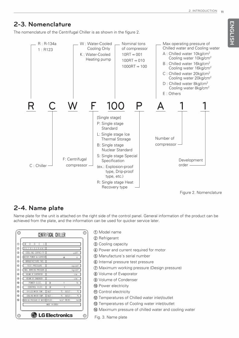
2-4. Name plateName plate for the unit is attached on the right side of the control panel. General information of the product can beachieved from the plate, and the information can be used for quicker service later.
Fig. 3. Name plate
① Model name
② Refrigerant
③ Cooling capacity
④ Power and current required for motor
⑤ Manufacture's serial number
⑥ Internal pressure test pressure
⑦ Maximum working pressure (Design pressure)
⑧ Volume of Evaporator
⑨ Volume of Condenser
⑩ Power electricity
⑪ Control electricity
⑫ Temperatures of Chilled water inlet/outlet
⑬ Temperatures of Cooling water inlet/outlet
⑭ Maximum pressure of chilled water and cooling water
2-3. NomenclatureThe nomenclature of the Centrifugal Chiller is as shown in the figure 2.
R C W F 100 P A 1 1
C : Chiller
F: Centrifugal
compressor
Number of
compressor
Developmentorder
[Single stage]
P: Single stageStandard
L: Single stage IceThermal Storage
B: Single stageNuclear Standard
S: Single stage SpecialSpecification
(ex.: Explosion-prooftype, Drip-prooftype, etc.)
R: Single stage HeatRecovery type
Max operating pressure ofChilled water and Cooling waterA : Chilled water 10kg/cm2
Cooling water 10kg/cm2
B : Chilled water 16kg/cm2
Cooling water 16kg/cm2
C : Chilled water 20kg/cm2
Cooling water 20kg/cm2
D : Chilled water 8kg/cm2
Cooling water 8kg/cm2
E : Others
Nominal tonsof compressor
10RT ⇨ 001
100RT ⇨ 010
1000RT ⇨ 100
W : Water-CooledCooling Only
K : Water-CooledHeating pump
R : R-134a
1 : R123
Figure 2. Nomenclature
ENG
LISH
12 2. INTRODUCTION
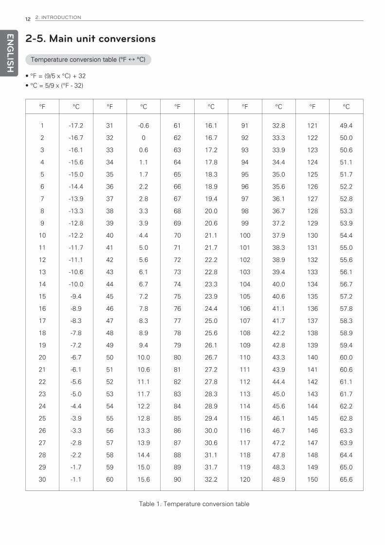
• °F = (9/5 x °C) + 32
• °C = 5/9 x (°F - 32)
2-5. Main unit conversions
°F °C °F °C °F °C °F °C °F °C
1
2
3
4
5
6
7
8
9
10
11
12
13
14
15
16
17
18
19
20
21
22
23
24
25
26
27
28
29
30
-17.2
-16.7
-16.1
-15.6
-15.0
-14.4
-13.9
-13.3
-12.8
-12.2
-11.7
-11.1
-10.6
-10.0
-9.4
-8.9
-8.3
-7.8
-7.2
-6.7
-6.1
-5.6
-5.0
-4.4
-3.9
-3.3
-2.8
-2.2
-1.7
-1.1
31
32
33
34
35
36
37
38
39
40
41
42
43
44
45
46
47
48
49
50
51
52
53
54
55
56
57
58
59
60
-0.6
0
0.6
1.1
1.7
2.2
2.8
3.3
3.9
4.4
5.0
5.6
6.1
6.7
7.2
7.8
8.3
8.9
9.4
10.0
10.6
11.1
11.7
12.2
12.8
13.3
13.9
14.4
15.0
15.6
61
62
63
64
65
66
67
68
69
70
71
72
73
74
75
76
77
78
79
80
81
82
83
84
85
86
87
88
89
90
16.1
16.7
17.2
17.8
18.3
18.9
19.4
20.0
20.6
21.1
21.7
22.2
22.8
23.3
23.9
24.4
25.0
25.6
26.1
26.7
27.2
27.8
28.3
28.9
29.4
30.0
30.6
31.1
31.7
32.2
91
92
93
94
95
96
97
98
99
100
101
102
103
104
105
106
107
108
109
110
111
112
113
114
115
116
117
118
119
120
32.8
33.3
33.9
34.4
35.0
35.6
36.1
36.7
37.2
37.9
38.3
38.9
39.4
40.0
40.6
41.1
41.7
42.2
42.8
43.3
43.9
44.4
45.0
45.6
46.1
46.7
47.2
47.8
48.3
48.9
121
122
123
124
125
126
127
128
129
130
131
132
133
134
135
136
137
138
139
140
141
142
143
144
145
146
147
148
149
150
49.4
50.0
50.6
51.1
51.7
52.2
52.8
53.3
53.9
54.4
55.0
55.6
56.1
56.7
57.2
57.8
58.3
58.9
59.4
60.0
60.6
61.1
61.7
62.2
62.8
63.3
63.9
64.4
65.0
65.6
Table 1. Temperature conversion table
Temperature conversion table (°F ↔ °C)

ENG
LISH
2. INTRODUCTION 13
• lb/in2 = psiex) 1 lb/in2 = 0.07030696 kg/cm2
lb/in2 kg/cm2 lb/in2 kg/cm2 lb/in2 kg/cm2 lb/in2 kg/cm2 lb/in2 kg/cm2
1
2
3
4
5
6
7
8
9
10
11
12
13
14
15
16
17
18
19
20
21
22
23
24
25
26
27
28
29
30
31
32
33
34
35
36
37
38
39
40
0.070
0.141
0.211
0.281
0.352
0.422
0.492
0.563
0.633
0.703
0.773
0.844
0.914
0.984
1.055
1.125
1.195
1.266
1.336
1.406
1.477
1.547
1.617
1.687
1.758
1.828
1.898
1.969
2.039
2.109
2.180
2.250
2.320
2.390
2.461
2.531
2.601
2.672
2.742
2.812
41
42
43
44
45
46
47
48
49
50
51
52
53
54
55
56
57
58
59
60
61
62
63
64
65
66
67
68
69
70
71
72
73
74
75
76
77
78
79
80
2.883
2.953
3.023
3.094
3.164
3.234
3.304
3.375
3.445
3.515
3.586
3.646
3.726
3.797
3.867
3.987
4.008
4.078
4.148
4.218
4.289
4.359
4.429
4.500
4.570
4.640
4.711
4.781
4.851
4.921
4.992
5.062
5.132
5.203
5.273
5.343
5.414
5.484
5.554
5.625
81
82
83
84
85
86
87
88
89
90
91
92
93
94
95
96
97
98
99
100
101
102
103
104
105
106
107
108
109
110
111
112
113
114
115
116
117
118
119
120
5.695
5.765
5.836
5.906
5.976
6.046
6.117
6.187
6.257
6.328
6.398
6.468
6.539
6.609
6.679
6.750
6.820
6.890
6.968
7.031
7.101
7.171
7.242
7.312
7.382
7.453
7.523
7.593
7.663
7.734
7.804
7.874
7.945
8.015
8.085
8.156
8.226
8.296
8.367
8.437
121
122
123
124
125
126
127
128
129
130
131
132
133
134
135
136
137
138
139
140
141
142
143
144
145
146
147
148
149
150
151
152
153
154
155
156
157
158
159
160
8.507
8.577
8.648
8.718
8.788
8.859
8.929
8.999
9.070
9.140
9.210
9.281
9.351
9.421
9.491
9.562
9.632
9.702
9.773
9.843
9.913
9.984
10.05
10.12
10.19
10.26
10.34
10.41
10.48
10.55
10.62
10.69
10.76
10.83
10.90
10.97
11.04
11.11
11.18
11.25
161
162
163
164
165
166
167
168
169
170
171
172
173
174
175
176
177
178
179
180
181
182
183
184
185
186
187
188
189
190
191
192
193
194
195
196
197
198
199
200
11.32
11.39
11.46
11.53
11.60
11.67
11.74
11.81
11.88
11.95
12.02
12.09
12.16
12.23
12.30
12.37
12.44
12.51
12.58
12.66
12.73
12.80
12.87
12.94
13.01
13.08
13.15
13.22
13.29
13.36
13.43
13.50
13.57
13.64
13.71
13.78
13.85
13.92
13.99
14.06
Table 2. Pressure conversion table
Pressure conversion table (lb/in2 ↔ kg/cm2)

ENG
LISH
14 3. STRUCTURE OF TWO STAGE CENTRIFUGAL CHILLER
3. STRUCTURE OF SINGLE STAGE CENTRIFUGALCHILLER
3-1. Cycle of the chillerSingle stage Standard Centrifugal Chiller
Cycle of the Centrifugal chiller is generally used for reciprocating same form as a screw refrigeration cycle, uses ahigh-pressure refrigerant R-134a. In this cycle, as shown in the Figure 1-1, the low temperature and low pressure re-frigerant gas vaporized from the evaporator goes through guide vane and taken into the impeller of the compressor.The amount of gas taken in at this time is adjusted by the opening of the guide vane to control the chiller capacity.The refrigerant gas taken into the impeller is compressed to high temperature and high pressure refrigerant gas, dis-charged to condenser, and condensed after losing heat by cooling water in the condenser heat transfer tubes. Thecondensed refrigerant liquid goes through the orifice and goes into the lower part of the evaporator, is distributedevenly through all length of the evaporator by the distribution plate, and is evaporated after taking heat from thechilled water flowing inside the evaporator heat transfer tubes, and the same cycle is repeated. Part of the refrigerantliquid over-cooled in the condenser flows through valve, filter, sight glass, and is separated and flows to motor cool-ing and oil cooling system. The refrigerant liquid that entered the motor is sprayed to cool down the motor coil andreturns to the evaporator. The refrigerant flowing to the oil cooling system flows to the plate type heat exchanger (oilcooler), and the refrigerant leaving the heat exchanger returns to the evaporator.
Compressor
Condenser
Cooling water inlet
Cooling water outlet
Refrigerant liquid
Refrigerant gas
Evaporator
Orifice
Chilled water outlet
Chilled water inlet
Fig 4. Single stage centrifugal chiller

ENG
LISH
3. STRUCTURE OF TWO STAGE CENTRIFUGAL CHILLER 15
3-2. Main components of the two stage centrifugal chiller
Compressor
*The single stage turbo chiller compressor is composed of an impeller, bearing, diffuser, capacity control device andhigh-speed gear. The low temperature and low pressured gas taken from the evaporator, goes through impeller, dif-fuser and is finally discharged to the condenser as high temperature high pressure gas.
The characteristics of the main components are as follows.
1. Impeller
- The vane of impeller designed aerodynamically based on the 3D fluid analysis, guarantees the reliability in any op-erational condition.
- To minimize vibration, the impeller takes on the dynamic balancing work. It also guarantees the overall reliabilityof the impellers by taking the strength test, hardness test, and non-destructive test.
2. Bearings
- Bearings are composed of a bearing in the motor axis, radial bearings and thrust bearings on the impeller axis.
- Bearings are made of white metal to achieve persistence and corrosion resistance. It is designed to be usedsafely avoiding metal to metal contact during operation as the lubricating structure of Figure 8.
- To increase the reliability of the journal bearings, Offset type and 3-Lobe type bearings are applied.
3. Capacity control device
- It adjusts the refrigerant amount taken through the compressor inlet to adjust the capacity of the chiller, and it ad-justs the opening of the vanes using the external actuator.
- The amount of refrigerant taken in is adjusted according to the set of chilled water outlet temperature.
Fig 5. Hermetic single stage high-speed compressor

ENG
LISH
16 3. STRUCTURE OF TWO STAGE CENTRIFUGAL CHILLER
Heat exchanger of single stage centrifugal chiller is composed of two shell type for easy separation into evaporatorand condenser. The tubes are arranged so as to maximize the heat exchanging ability. It is also designed so that therefrigerant can be spread evenly on all tubes for the sake of surge prevention and the COP decrease in part load oper-ation. Efficiency increasing purpose sub cooler is adopted for the subcool of the condensed refrigerant.A relief valve for an abnormal situation is at the upper part of the heat exchanger.
Heat exchanger
Relief valve
Body
Refrigerantdistributor
Refrigerant outlet
Tubes
Baffle
Accumulator
Tubes
Relief valve
Waterbox
Body
Waterbox
Refrigerant outletRefrigerant inlet
Figure 6. Evaporator Figure 7. Condenser

ENG
LISH
3. STRUCTURE OF TWO STAGE CENTRIFUGAL CHILLER 17
Introduction
The discharged lubricating oil by the oil pump enters the oil filter to get rid of any unnecessary foreign substance.This oil becomes cooled to the temperature appropriate for operation condition after through the oil cooler, part of itdirectly enters gear and high speed side bearings, and the remainder directly enters motor shaft bearings. After theprocess, it will be drained into the oil tank. The above figure shows the lubrication system of single stage compres-sion type.
Lubrication cycle
Lubricating oil is forwarded through the manual oil charge valve to the Lubrication System.Oil level can be detected through a sight glass on the oil tank. During the operation, the level should be able to be de-tected at least from one of them.The temperature of the oil tank is indicated on the control panel and its temperature range is 30~65 °C while operat-ing. What the oil pump does is to transfer the oil from the oil tank to the system and the adequate pressure differentwould be 1.0 kg/cm2 that is maintained by the oil pressure controller. The differential pressure can be seen on thecontrol panel pressure gauge display by the differential pressure between oil tank and oil pump.
The oil pump also helps to send the oil to the oil filter. A valve is installed at the oil filter so that no need to drain thewhole oil when replacing the filter only. After the oil is sent to the oil cooler it is cooled by the refrigerant flowing from the condenser. The refrigerant coolsthe oil at the temperature between 40~60 °C.A part of the oil flows through the thrust bearing and gear spray, whereas the rest lubricates the motor shaft bearingsand the radial bearings. The oil temperature in the oil tank is measured by temperature sensor and displayed. The timer automatically activates the oil pump for 120~180 seconds to maintain a constant pressure first beforestarting compressor. After the system has been shut down, 300~600 seconds lubricating is taken place after thecompressor is stopped.
Lubrication system
Oil inlet
Oil coolerOil filter
Oil pump & motorSight glass
Oil outlet
Oil pressure transducer
Oil outletOil tank
Bearing
Bearing
Oil pressureregulatorOil pressureregulator Oil inlet
Figure 9. Lubrication cycle
ENG
LISH
18 3. STRUCTURE OF TWO STAGE CENTRIFUGAL CHILLER
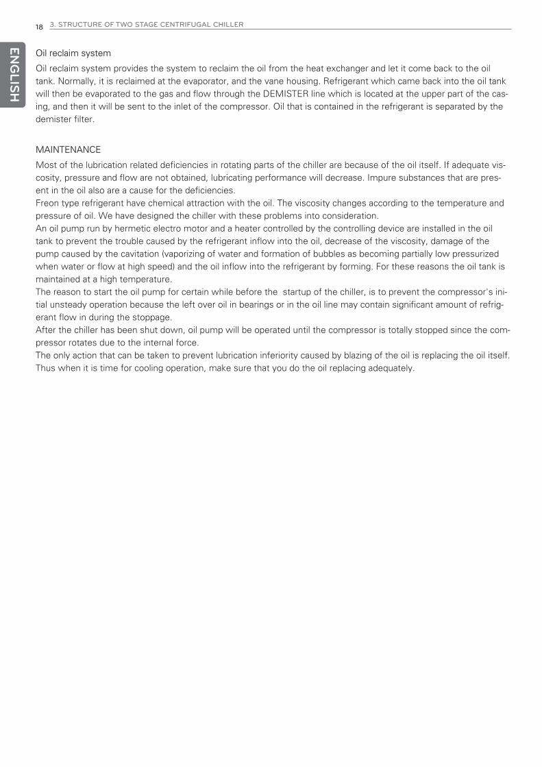
Oil reclaim system
Oil reclaim system provides the system to reclaim the oil from the heat exchanger and let it come back to the oiltank. Normally, it is reclaimed at the evaporator, and the vane housing. Refrigerant which came back into the oil tankwill then be evaporated to the gas and flow through the DEMISTER line which is located at the upper part of the cas-ing, and then it will be sent to the inlet of the compressor. Oil that is contained in the refrigerant is separated by thedemister filter.
MAINTENANCE
Most of the lubrication related deficiencies in rotating parts of the chiller are because of the oil itself. If adequate vis-cosity, pressure and flow are not obtained, lubricating performance will decrease. Impure substances that are pres-ent in the oil also are a cause for the deficiencies.Freon type refrigerant have chemical attraction with the oil. The viscosity changes according to the temperature andpressure of oil. We have designed the chiller with these problems into consideration.An oil pump run by hermetic electro motor and a heater controlled by the controlling device are installed in the oiltank to prevent the trouble caused by the refrigerant inflow into the oil, decrease of the viscosity, damage of thepump caused by the cavitation (vaporizing of water and formation of bubbles as becoming partially low pressurizedwhen water or flow at high speed) and the oil inflow into the refrigerant by forming. For these reasons the oil tank ismaintained at a high temperature.The reason to start the oil pump for certain while before the startup of the chiller, is to prevent the compressor's ini-tial unsteady operation because the left over oil in bearings or in the oil line may contain significant amount of refrig-erant flow in during the stoppage.After the chiller has been shut down, oil pump will be operated until the compressor is totally stopped since the com-pressor rotates due to the internal force.The only action that can be taken to prevent lubrication inferiority caused by blazing of the oil is replacing the oil itself.Thus when it is time for cooling operation, make sure that you do the oil replacing adequately.

ENG
LISH
3. STRUCTURE OF TWO STAGE CENTRIFUGAL CHILLER 19
For the sake of safe operation and the protection of the chiller, safety devices are ready as the next table.
Safety devices
No. Safety DevicesInstallationLocation
Measurement Item DescriptionQuan-
tity
1Chilled WaterTemperature
Low
Chilled waterinlet nozzle
Chilled water inlettemperature
Chiller stops operation if the chilled water outlettemperature below 3°C to prevent freezing of thechilled water. Do not change this set value.
1
2
EvaporatorPressure Low(Temperature
Low)
Evaporatorshell
Vaporizing pressure(temp.)
If the pressure inside of evaporator reachesbelow of the following table, then the chillerstops operation. (Based on the design tempera-ture 43 ℃)
1
3
CondenserPressure High(Temperature
High)
Condensershell
Condensing pressure(temperature)
If the pressure inside of condenser reaches aboveof the following table, then the chiller stops opera-tion.(Based on the design temperature 43 ℃) 1
4Motor Temper-
ature HighMotor coil
Motor coil tempera-ture
To prevent the motor of the compressor, temper-ature sensors were installed on each phase ofcoil and when the temperature exceeds 90°C,the chiller stops operation.
3
5CompressorTemperature
High
Compressoroutlet
Compressor dis-charge temperature
If the discharging gas temperature of the com-pressor exceeds over 70°C, the chiller stops op-eration.
1
6Bearing Tem-perature High
Thrust bearing Bearing temperature
Temperature sensor is installed on the thrustbearing that holds the impeller's thrust. Chillerwill stop operation if the temperature exceeds85°C.
1
7Oil DifferentialPressure Low
Oil tank, oilpump outlet
Differential pressureof supplied and intake
oil pressure
If the differential pressure between the oil pres-sure supplied to the bearing and the oil pressurein the oil tank is below 1.0 kg/cm2, the chiller willstop the operation.
1
8Oil Tempera-
ture HighOil tank
Oil temperature in-side of oil tank
The chiller will stop if the oil temperature in theoil tank is above 74°C.
1
9Oil Tempera-
ture LowOil tank
Oil temperature in-side of oil tank
The temperature should be over 30°C as an initialoperating condition to enable the chiller to oper-ate.
1
10Chilled WaterPump Abnor-
mal
Chilled waterheader
Chilled water headloss
The chiller will stop if the head loss of the chilledwater flow passing through the evaporator tubesdecreases so much that the loss head becomeslower than the standard.
1
11Cooling WaterPump Abnor-
mal
Cooling waterheader
Cooling water headloss
The chiller will stop if the head loss of the coolingwater flow passing through the condenser tubesdecreases so much that the loss head becomeslower than the standard.
1
12Current Limit-ing Function
Control panel Current
It is a controlling function of Motor Amps thatcan be set freely in the range of 40 ~ 100% toadjust the current load to the motor of compres-sor.
1
13Moisture Indi-
catorRefrigerantsupply pipe
Moisture in the refrig-erant
The moisture indicator changes the color dependingon the amount of moisture in the refrigerant. Whenthere is no moisture it will be green, but if not it willbe yellow. It is the time to change into a new filterif you can see the yellow color.
1
Standard setting value 1.95kg/cm2
Standard setting value 10.00kg/cm2
ENG
LISH
20 3. STRUCTURE OF TWO STAGE CENTRIFUGAL CHILLER
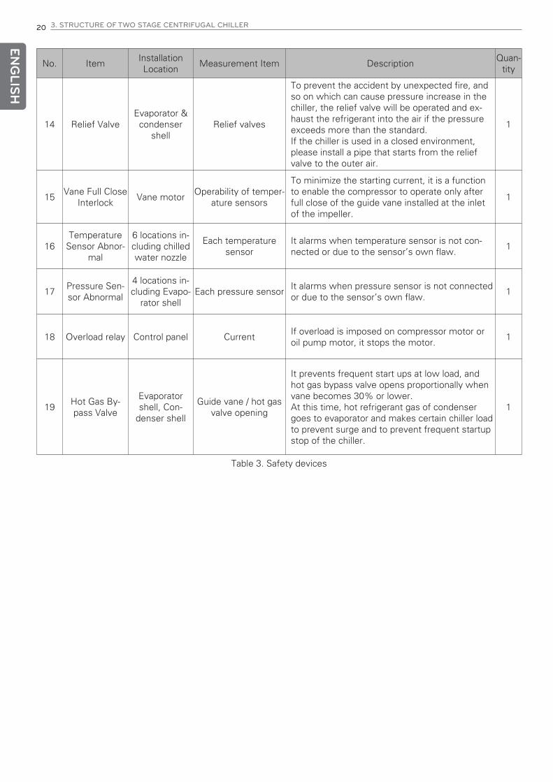
No. ItemInstallationLocation
Measurement Item DescriptionQuan-
tity
14 Relief ValveEvaporator &condenser
shellRelief valves
To prevent the accident by unexpected fire, andso on which can cause pressure increase in thechiller, the relief valve will be operated and ex-haust the refrigerant into the air if the pressureexceeds more than the standard. If the chiller is used in a closed environment,please install a pipe that starts from the reliefvalve to the outer air.
1
15Vane Full Close
InterlockVane motor
Operability of temper-ature sensors
To minimize the starting current, it is a functionto enable the compressor to operate only afterfull close of the guide vane installed at the inletof the impeller.
1
16Temperature
Sensor Abnor-mal
6 locations in-cluding chilledwater nozzle
Each temperaturesensor
It alarms when temperature sensor is not con-nected or due to the sensor’s own flaw.
1
17Pressure Sen-sor Abnormal
4 locations in-cluding Evapo-
rator shellEach pressure sensor
It alarms when pressure sensor is not connectedor due to the sensor’s own flaw.
1
18 Overload relay Control panel CurrentIf overload is imposed on compressor motor oroil pump motor, it stops the motor.
1
19Hot Gas By-pass Valve
Evaporatorshell, Con-
denser shell
Guide vane / hot gasvalve opening
It prevents frequent start ups at low load, andhot gas bypass valve opens proportionally whenvane becomes 30% or lower. At this time, hot refrigerant gas of condensergoes to evaporator and makes certain chiller loadto prevent surge and to prevent frequent startupstop of the chiller.
1
Table 3. Safety devices

ENG
LISH
4. CONTROL SYSTEM 21
4. CONTROL SYSTEM4-1. Components of control panel and main parts
HMI with 7 inch Color LCD display is composed of graphical interface.There are lamp keys for run/stop, vane and oil pump, compressor, oil pump, oil heater operation and cooling/chilledwater flow.There is “Function Key” at the bottom of the screen that changes the features according to the current screen to beable to access to the selected sub menu.
Controller
Function key
Fig 10. Controller
Front view of the controller Rear view of the controller
Internal diagram of the controllerConfiguration part of KEY & LED

ENG
LISH
22 4. CONTROL SYSTEM
Master board and slave board are identical in hardware. It can be either master or slave by the set of DIP switch.
(SW4 OFF: Master, ON: Slave). For the user’s convenience, digital input/output connected via RS232, RS485 com-munication connections is available along with the analogue input/output.
Figure 11. Internal diagram of master/slave board
Power module
PowerFilter
Power Input
Power module
Commu-nication
Commu-nication

ENG
LISH
4. CONTROL SYSTEM 23
Controller system diagram
Master, slave, HMI, Relay board communicates via RS485. On either one of master or slave board have analog input(temperature 12 channel, current 10 channel), analog output (current 4 channel), digital input (20 channel), and digitaloutput (16 channel).Relay board controls guide vane and diffuser vane.
UART(MAIN)
RS485
RS485RS485
HMI: screen display and communication
RELAY: Controls guide vane and diffuser vane SLAVE: Controls temperature,pressure and digital input/output
MASTER: Controls temperature,pressure and digital input/output
LCDDISPLAY(7inch)
KEY-PAD
DATADOWN
UART(DISPLAY)
UART(BMS)
UART(Slave)
MICOM
PT100INPUT
4-20mAINPUT
4-20mAOUTPUT
DIGITALINPUT
DIGITAL OUTPUT
UART(BMS)
UART(Slave)
UART(DISPLAY)
MICOM
DC 0~5VINPUT
DIGITALOUTPUT
MICOM
UART(Master)
PT100INPUT
4-20mAINPUT
4-20mAOUTPUT
DIGITALINPUT
DIGITAL OUTPUT
RS485
RS485
RS485
DC 0~5VINPUT
DIGITALOUTPUT
UART(Master)
LCDDISPLAY(7inch)
KEY-PAD
MICOM(ARM)
UART(MAIN)
DATADOWN
UART(DISPLAY)
UART(BMS)
UART(Slave)
MICOM
PT100INPUT
4-20mAINPUT
4-20mAOUTPUT
DIGITALINPUT
DIGITAL OUTPUT
UART(BMS)
UART(Slave)
UART(DISPLAY)
MICOM
PT100INPUT
4-20mAINPUT
4-20mAOUTPUT
DIGITALINPUT
DIGITAL OUTPUT
HMI: screen display and communication
RELAY: Controls guide vane and diffuser vane SLAVE: Controls temperature,pressure and digital input/output
MASTER: Controls temperature,pressure and digital input/output
Fig 12. Controller block diagram

ENG
LISH
24 4. CONTROL SYSTEM
① Breaker
② Relay
③ Magnetic
④ Contactor
⑤ Thermal relay
⑥ Buzzer
⑦ Terminal strip
⑧ Transformer
⑨ Noise filter
⑩ Fuse
⑪ Relay board
⑫ Master board
Other control parts
Fig 13 Control system.
h The above configuration may be changed for the sake of the improvement of design, product or user convenience.Thus, please refer to the approved drawings for details.
① Breaker
⑧ Transformer ⑨ Noise filter ⑩ Fuse ⑪ Relay board ⑫ Master board
② Relay
③ Magnetic
④ Contactor
⑤ Thermal relay
⑥ Buzzer
⑦ Terminal strip

ENG
LISH
4. CONTROL SYSTEM 25
BACnet converter
The controllers from LG basically support Modbus communication protocol.If the higher level communication protocol is BACnet, you need to apply a separate BACnet converter for protocolconversion.
Communication converter is installed inside the control panel.Please refer to the following table for the meaning and description of each lamp.
Optional parts related controller
Fig 14. Converter
Table 4. Lamps on the converter
LED name Condition Description
TX485
RX485
Flashing Normal data communication with MICOM
Off Error, Check communication line
TX232
RX232
Flashing Normal data communication with BACnet
Off Error, check communication line
RUNFlashing every second Board finished Power-on test, and in normal operating
Maintaining On/Off Error, Press the reset button or turn off power & reboot.
ETX
ERX
ELK
LED on at Ethernet LineELK is always on when LAN cable is connected. ERX flashes on data
reception. ETX flashes on data transmission.
ENG
LISH
26 4. CONTROL SYSTEM
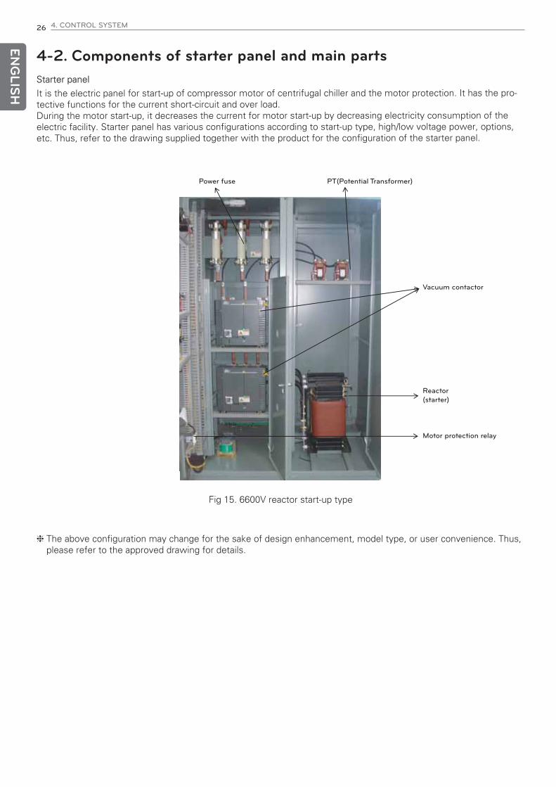
4-2. Components of starter panel and main partsStarter panel
It is the electric panel for start-up of compressor motor of centrifugal chiller and the motor protection. It has the pro-tective functions for the current short-circuit and over load.During the motor start-up, it decreases the current for motor start-up by decreasing electricity consumption of theelectric facility. Starter panel has various configurations according to start-up type, high/low voltage power, options,etc. Thus, refer to the drawing supplied together with the product for the configuration of the starter panel.
Power fuse PT(Potential Transformer)
Vacuum contactor
Reactor(starter)
Motor protection relay
Fig 15. 6600V reactor start-up type
h The above configuration may change for the sake of design enhancement, model type, or user convenience. Thus,please refer to the approved drawing for details.
ENG
LISH
4. CONTROL SYSTEM 27
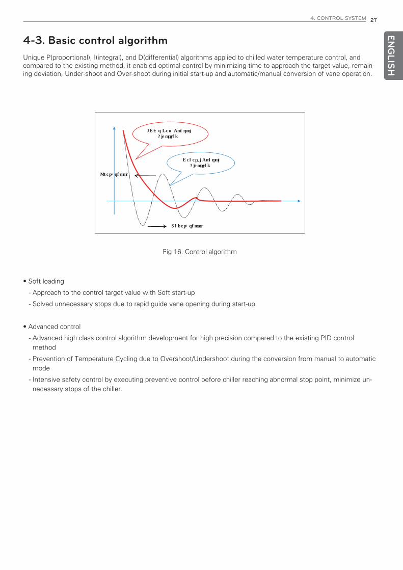
4-3. Basic control algorithmUnique P(proportional), I(integral), and D(differential) algorithms applied to chilled water temperature control, andcompared to the existing method, it enabled optimal control by minimizing time to approach the target value, remain-ing deviation, Under-shoot and Over-shoot during initial start-up and automatic/manual conversion of vane operation.
Under-shoot
Over-shoot
LG’s New ControlAlgorithm
General ControlAlgorithm
Fig 16. Control algorithm
• Soft loading
- Approach to the control target value with Soft start-up
- Solved unnecessary stops due to rapid guide vane opening during start-up
• Advanced control
- Advanced high class control algorithm development for high precision compared to the existing PID controlmethod
- Prevention of Temperature Cycling due to Overshoot/Undershoot during the conversion from manual to automaticmode
- Intensive safety control by executing preventive control before chiller reaching abnormal stop point, minimize un-necessary stops of the chiller.
ENG
LISH
28 4. CONTROL SYSTEM
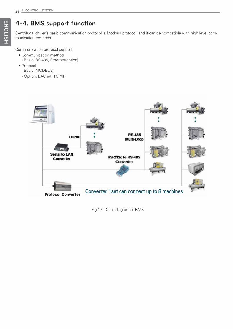
4-4. BMS support functionCentrifugal chiller’s basic communication protocol is Modbus protocol, and it can be compatible with high level com-munication methods.
Communication protocol support
• Communication method- Basic: RS-485, Ethernet(option)
• Protocol- Basic: MODBUS
- Option: BACnet, TCP/IP
Converter 1set can connect up to 8 machinesProtocol Converter
Fig 17. Detail diagram of BMS

ENG
LISH
4. CONTROL SYSTEM 29
4-5. Control Screen (Product function)
• User setting
Controller Menu Configuration
User setting Refrigerant level setting System Information (Output) Account management
Running Mode setting
Control Mode setting
Chilled water outlet temperature
Ice Making outlet temperature
Chilled water temperature P
Chilled water temperature I
Chilled water temperature D
Automatic Operation temperature (set value +)
Automatic Stopping temperature (set value -)
Antifreeze Operation function
Antifreeze Operation temperature
Motor Current limit Manual operation
Guide Vane Upper Limit Vane opening
Hot gas setting (Guide vane %) Diffuser opening
Hot gas upper limit setting Hot gas opening
Hot gas lower limit setting ECO valve manual
Cooling water inlet temperature CON valve manual
Cooling water temperature P
Cooling water temperature I System Information (Input)
Cooling water temperature D
System Information (Timer)
Dual Mode setting
Lead/Lag Conversion Method selection
Lead/Lag Conversion Time selection
LAG Start-up Load (current %)
LAG Start-up Delay time
LAG Stop Load (current %)
LAG Stop Delay time
Scheduled operation setting
Scheduled Operation Pattern setting (Run)
Scheduled Operation Pattern setting (Stop)
Scheduled Operation Pattern setting (Temperature)
Scheduled Operation Pattern setting (Current)
System Information
Input Status check
Output Status check
Timer Check
Operation data saving period
Communication ID (machine number)
Baud rate
Language
Temperature unit selection
Pressure Unit selection
Flow Unit selection
LCD brightness control
ECO Refrigerant level setting
ECO Refrigerant level P
ECO Refrigerant level I
ECO Refrigerant level dead band
ECO Refrigerant level valve initial value
CON Refrigerant level setting
CON Refrigerant level P
CON Refrigerant level I
CON Refrigerant level dead band
CON Refrigerant level valve initial value
Ice Making mode selection
Remote Selection display
Chilled water Pump operation
Cooling water Pump operation
Cooling Tower Fan 1 operation
Cooling Tower Fan 2 operation
Cooling Tower Fan 3 operation
Cooling Tower Fan 4 operation
Hot Gas Valve
Inverter
Oil Heater Run
Oil Pump Run
Buzzer
Operation Status display
Warning Status display
Display of Abnormal Status
Compressor Operation Status
Vane Opening
Diffuser Opening
Management No. 1
Management No. 2
Management No. 3
System Setting Password
Operation Remaining time
Chilled water inlet temperature.
Chilled water outlet temperature
Cooling water inlet temperature
Cooling water outlet temperature
Evaporator temperature
Condenser temperature
Evaporator pressure
Condenser pressure
Chilled water flow normal contact
Cooling water flow
Remote temperature setting *
Hot Gas Valve AO *
VFD AO *
Motor Bearing temperature *
Heat Recovery temperature
Compressor Discharge temperature
Oil temperature
Bearing temperature *
Motor Winding temperature (R) *
Motor Winding temperature (S) *
Motor Winding temperature (T) *
Oil Tank Pressure *
Oil Pump Pressure
Current
Voltage *
Power *
Guide Vane AO *
Diffuser Vane AO *
Vibration sensor *
Compressor discharge temperature 2
Oil temperature 2
Bearing temperature 2
Motor Winding temperature (R) 2 *
Motor Winding temperature (S) 2 *
Motor Winding temperature (T) 2*
Oil Tank Pressure 2 *
Oil Pump Pressure 2
Current 2
Voltage 2 *
Power 2 *
Guide Vane AO 2 *
Diffuser Vane AO 2 *
Relay 1
Relay 2
Ice Making mode selection
Remote Run/Stop signal
Refrigerant temperature low contact
Condenser Pressure high contact
Chilled water Flow normal contact
Cooling water Flow normal contact
Chilled water Pump interlock
Cooling water Pump interlock
Key Lock
Input 10
Bearing temperature high contact
Motor Winding temperature high contact
Oil Pump Overload contact
Vane Closing contact
Compressor Motor Power Normal
Compressor Start-up check
Starter Abnormal
Diffuser Manual
Diffuser Manual close
Diffuser Manual open
Chilled water Pump Stop Delay Timer
Cooling water Pump Start-up Delay Timer
Cooling water Pump Stop Delay Timer
Flow Chattering Ignore Timer
VGD control Delay Timer
Oil Circulation timer before Run
Oil Circulation timer after Stop
Oil Pressure Check Timer
Vane Close Timer at Start-up
Vane Close Timer at Stop
Vane Open Delay timer
Compressor Start-up Check Timer
Anti-Recycle Timer
ENG
LISH
30 4. CONTROL SYSTEM
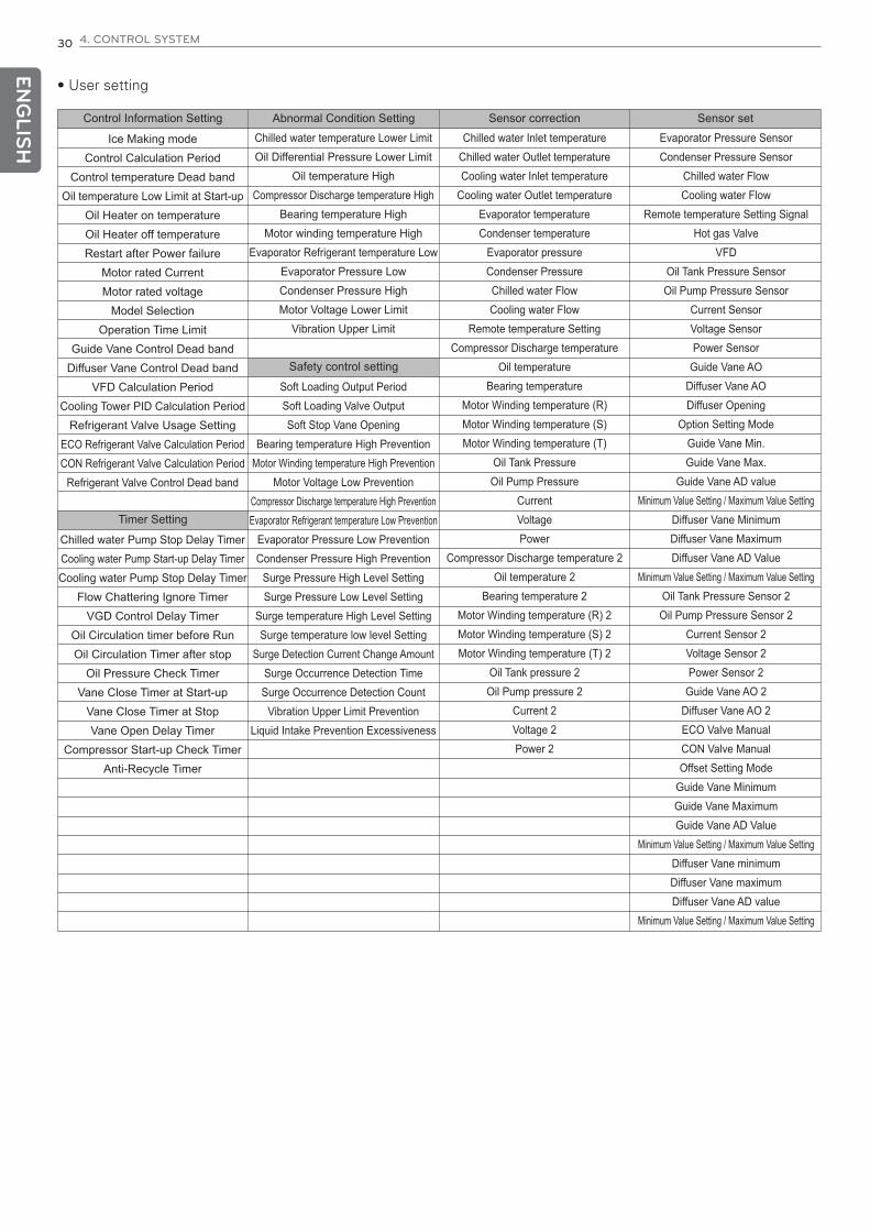
• User setting
Control Information Setting Abnormal Condition Setting Sensor correction Sensor set
Safety control setting
Timer Setting
Ice Making mode
Control Calculation Period
Control temperature Dead band
Oil temperature Low Limit at Start-up
Oil Heater on temperature
Oil Heater off temperature
Restart after Power failure
Motor rated Current
Motor rated voltage
Model Selection
Operation Time Limit
Guide Vane Control Dead band
Diffuser Vane Control Dead band
VFD Calculation Period
Cooling Tower PID Calculation Period
Refrigerant Valve Usage Setting
ECO Refrigerant Valve Calculation Period
CON Refrigerant Valve Calculation Period
Refrigerant Valve Control Dead band
Chilled water Pump Stop Delay Timer
Cooling water Pump Start-up Delay Timer
Cooling water Pump Stop Delay Timer
Flow Chattering Ignore Timer
VGD Control Delay Timer
Oil Circulation timer before Run
Oil Circulation Timer after stop
Oil Pressure Check Timer
Vane Close Timer at Start-up
Vane Close Timer at Stop
Vane Open Delay Timer
Compressor Start-up Check Timer
Anti-Recycle Timer
Chilled water temperature Lower Limit
Oil Differential Pressure Lower Limit
Oil temperature High
Compressor Discharge temperature High
Bearing temperature High
Motor winding temperature High
Evaporator Refrigerant temperature Low
Evaporator Pressure Low
Condenser Pressure High
Motor Voltage Lower Limit
Vibration Upper Limit
Chilled water Inlet temperature
Chilled water Outlet temperature
Cooling water Inlet temperature
Cooling water Outlet temperature
Evaporator temperature
Condenser temperature
Evaporator pressure
Condenser Pressure
Chilled water Flow
Cooling water Flow
Remote temperature Setting
Compressor Discharge temperature
Oil temperature
Bearing temperature
Motor Winding temperature (R)
Motor Winding temperature (S)
Motor Winding temperature (T)
Oil Tank Pressure
Oil Pump Pressure
Current
Voltage
Power
Compressor Discharge temperature 2
Oil temperature 2
Bearing temperature 2
Motor Winding temperature (R) 2
Motor Winding temperature (S) 2
Motor Winding temperature (T) 2
Oil Tank pressure 2
Oil Pump pressure 2
Current 2
Voltage 2
Power 2
Evaporator Pressure Sensor
Condenser Pressure Sensor
Chilled water Flow
Cooling water Flow
Remote temperature Setting Signal
Hot gas Valve
VFD
Oil Tank Pressure Sensor
Oil Pump Pressure Sensor
Current Sensor
Voltage Sensor
Power Sensor
Guide Vane AO
Diffuser Vane AO
Diffuser Opening
Option Setting Mode
Guide Vane Min.
Guide Vane Max.
Guide Vane AD value
Minimum Value Setting / Maximum Value Setting
Diffuser Vane Minimum
Diffuser Vane Maximum
Diffuser Vane AD Value
Minimum Value Setting / Maximum Value Setting
Oil Tank Pressure Sensor 2
Oil Pump Pressure Sensor 2
Current Sensor 2
Voltage Sensor 2
Power Sensor 2
Guide Vane AO 2
Diffuser Vane AO 2
ECO Valve Manual
CON Valve Manual
Offset Setting Mode
Guide Vane Minimum
Guide Vane Maximum
Guide Vane AD Value
Minimum Value Setting / Maximum Value Setting
Diffuser Vane minimum
Diffuser Vane maximum
Diffuser Vane AD value
Minimum Value Setting / Maximum Value Setting
Soft Loading Output Period
Soft Loading Valve Output
Soft Stop Vane Opening
Bearing temperature High Prevention
Motor Winding temperature High Prevention
Motor Voltage Low Prevention
Compressor Discharge temperature High Prevention
Evaporator Refrigerant temperature Low Prevention
Evaporator Pressure Low Prevention
Condenser Pressure High Prevention
Surge Pressure High Level Setting
Surge Pressure Low Level Setting
Surge temperature High Level Setting
Surge temperature low level Setting
Surge Detection Current Change Amount
Surge Occurrence Detection Time
Surge Occurrence Detection Count
Vibration Upper Limit Prevention
Liquid Intake Prevention Excessiveness

ENG
LISH
4. CONTROL SYSTEM 31
Controlling menu and the names of control panel part
Two Stage centrifugal chiller control device display has the basic screen that can check the current operation status,main menu for user to conveniently use two Stage centrifugal chiller such as user setting, problem/caution informa-tion, etc., and system menu for sensor setting, system related setting.
Controller Menu Configuration
Start/stop key
Status display lamp
7” Color wide LCD
Menu operation key
Alarm lamp Yellow
Guide vane operation key
Oil pump operation key
Fig 18. Front side of controller
! CAUTION
Do not operate controller with sharp object.
It may cause controller damage.

ENG
LISH
32 4. CONTROL SYSTEM
Names of control part
Name Description
LCD screenIt is the LCD screen displaying the operation information and the status of the chillerin text (Korean, English and Chinese) or graphical animation.
Menu Control Key
These are keys are for selecting the menu on the screen such as selection of sub-menu and operation conditions.The functions keys shown at the bottom of the LCD screen changes depending onthe selected screen.
Guide vane manualcontrol key
It opens and closes the guide vane manually.
Manual control of the guide vane is possible only when the Vane Manual indicationlight is on.
Open/Close key- operates only while pressed.
Oil Pump Manual Control Key
It is to run and stop the oil pump manually.
Manual control is possible only when the Oil Pump Manual lamp is on. To enable themanual control, it has to be pushed for approximately 1.5seconds.
Alarm Lamp
It is activated on the condition of abnormality or cautious status.
If this is activated, an alarm message explaining the status is displayed on the mes-sage line. When alarm is activated, Cancel key is also displayed with buzzer sound.If the Cancel key is pressed, the buzzer sound will stop as the Cancel key disap-pears. And If the cause of the abnormality is taken care of, the message will also bedisappeared.
Run/Stop key
It is the key to run and stop the chiller.
To activate this button, it must be pressed for more than 1.5 seconds. During thechiller operation “Run” lamp is on, and when stopped “Stop” lamp on.
Status Indicating LampThese display the status of operation of the chiller and the devices attached on thechiller such as oil pump, oil heater and the flow condition of chilled & cooling water.
Table 5. Names of operation part

ENG
LISH
4. CONTROL SYSTEM 33
Names of Color LCD screen display part
Selected operation method display Selected operation mode display
Current time & menu
Message display Key menu bar
Selected chiller type display
Displayed categories Displayed items
Fig 19. LED screen diagram
① Selected operation method displayThere are Local, Schedule and Remote modes selecting how to operate the chiller. That is, Local is to operate thechiller at the local place where the chiller is, Schedule to operate on the scheduled time and Remote to operate ina remote place. It indicates the current operation mode on the screen.
② Selected chiller type displayChiller type can be selected among R134a 2 stage, R134 and R123.(When one is selected, it automatically resets the main board, and changes to the selected chiller type mode.)
③ Selected operation mode displayThere is only a cooling mode for the air-conditioning chillers. Thus only Cooling mode will be displayed. If it is thechiller for low temperature, it will display Cooling and Icing according to the setting. (Refer to the user setting ofmain menu and control mode)
④ Current time displayIt displays the current year, month, day, day of week, hour, and minute information.
⑤ Displayed itemsIt displays current operation temperatures, pressures and other current status information of the parts with sen-sors.
⑥ Key menu barIt displays the functions of menu control keys.
⑦ Message DisplayIt displays Run/Stop, operation condition, problem/caution, etc.
ENG
LISH
34 4. CONTROL SYSTEM
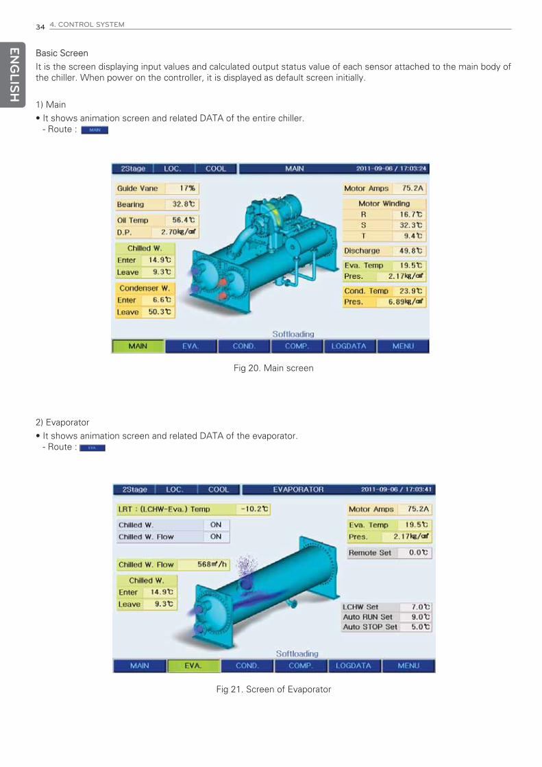
Basic Screen
It is the screen displaying input values and calculated output status value of each sensor attached to the main body ofthe chiller. When power on the controller, it is displayed as default screen initially.
1) Main
• It shows animation screen and related DATA of the entire chiller.- Route :
2) Evaporator
• It shows animation screen and related DATA of the evaporator.- Route :
Fig 20. Main screen
Fig 21. Screen of Evaporator

ENG
LISH
4. CONTROL SYSTEM 35
3) Condenser
• It shows animation screen and related DATA of the condenser.- Route :
4) Compressor
• It shows animation screen and related DATA of the compressor.- Route :
Figure 22. Screen of Condenser
Figure 23. Screen of Compressor
ENG
LISH
36 4. CONTROL SYSTEM
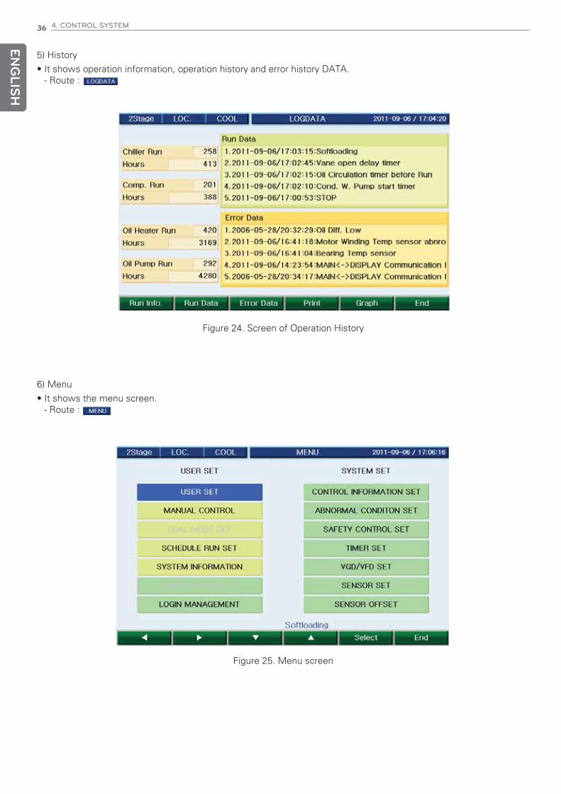
5) History
• It shows operation information, operation history and error history DATA.- Route :
6) Menu
• It shows the menu screen.- Route :
Figure 24. Screen of Operation History
Figure 25. Menu screen
ENG
LISH
4. CONTROL SYSTEM 37
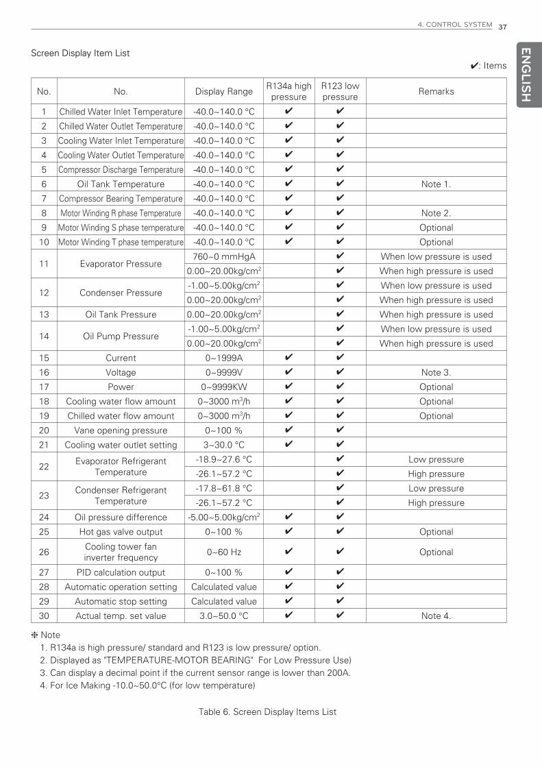
Screen Display Item List
No. No. Display RangeR134a high
pressureR123 lowpressure
Remarks
1 Chilled Water Inlet Temperature -40.0~140.0 °C 4 4
2 Chilled Water Outlet Temperature -40.0~140.0 °C 4 4
3 Cooling Water Inlet Temperature -40.0~140.0 °C 4 4
4 Cooling Water Outlet Temperature -40.0~140.0 °C 4 4
5 Compressor Discharge Temperature -40.0~140.0 °C 4 4
6 Oil Tank Temperature -40.0~140.0 °C 4 4 Note 1.
7 Compressor Bearing Temperature -40.0~140.0 °C 4 4
8 Motor Winding R phase Temperature -40.0~140.0 °C 4 4 Note 2.
9 Motor Winding S phase temperature -40.0~140.0 °C 4 4 Optional
10 Motor Winding T phase temperature -40.0~140.0 °C 4 4 Optional
11 Evaporator Pressure760~0 mmHgA 4 When low pressure is used
0.00~20.00kg/cm2 4 When high pressure is used
12 Condenser Pressure-1.00~5.00kg/cm2 4 When low pressure is used
0.00~20.00kg/cm2 4 When high pressure is used
13 Oil Tank Pressure 0.00~20.00kg/cm2 4 When high pressure is used
14 Oil Pump Pressure-1.00~5.00kg/cm2 4 When low pressure is used
0.00~20.00kg/cm2 4 When high pressure is used
15 Current 0~1999A 4 4
16 Voltage 0~9999V 4 4 Note 3.
17 Power 0~9999KW 4 4 Optional
18 Cooling water flow amount 0~3000 m3/h 4 4 Optional
19 Chilled water flow amount 0~3000 m3/h 4 4 Optional
20 Vane opening pressure 0~100 % 4 4
21 Cooling water outlet setting 3~30.0 °C 4 4
22Evaporator Refrigerant
Temperature-18.9~27.6 °C 4 Low pressure
-26.1~57.2 °C 4 High pressure
23Condenser Refrigerant
Temperature-17.8~61.8 °C 4 Low pressure
-26.1~57.2 °C 4 High pressure
24 Oil pressure difference -5.00~5.00kg/cm2 4 4
25 Hot gas valve output 0~100 % 4 4 Optional
26Cooling tower faninverter frequency
0~60 Hz 4 4 Optional
27 PID calculation output 0~100 % 4 4
28 Automatic operation setting Calculated value 4 4
29 Automatic stop setting Calculated value 4 4
30 Actual temp. set value 3.0~50.0 °C 4 4 Note 4.
4: Items
h Note1. R134a is high pressure/ standard and R123 is low pressure/ option.2. Displayed as "TEMPERATURE-MOTOR BEARING" For Low Pressure Use)3. Can display a decimal point if the current sensor range is lower than 200A.4. For Ice Making -10.0~50.0°C (for low temperature)
Table 6. Screen Display Items List

ENG
LISH
38 4. CONTROL SYSTEM
7) Main menu
• Main menu mainly has user setting and system setting as in the following figure.
- Users can set user set, dual set, schedule set and system information.
- Login management, sensor correction, control information setting, abnormal condition setting, safety control set-ting, timer setting, VGD/VFD setting and sensor setting, can only be set by system manager with password input.
• Menu screen
- Route :
111 22
Figure 26. Input status check screen
1 2
When a menu selected using ① button, it moves to the sub menu.
When 'Select' at ② button pressed, it moves to the MENU page. When 'End' button pressed, it returns to the de-fault BASIC screen.

ENG
LISH
4. CONTROL SYSTEM 39
- Descriptions of Main menu
Displayed items Usage
USER SETIt is the menu for users to set values required for chiller operation such as controltarget temperature, PID value, etc.
DUAL MODE SET It is the menu to set categories used in Dual Compressor
SCHEDULE RUN SETIt is the menu to set time for chiller to automatically start/stop at the designatedtime and the temperature for each time period.
System informationMenu to check overall system information such as I/O, timer operation, version, cur-rent time, operation information saving period, communication address, communica-tion speed, language setting, model selection, etc.
SYSTEM INFORMATIONIt is the menu to check overall system information such as I/O status, timer opera-tion, version, current time, operation information saving period, communication ad-dress, baud rate, language, machine type, etc.
LOGIN MANAGEMENT It is the menu to change password and management number.
SENSOR CORRECTION It is the Menu to set the most basic information in the chiller operation
SAFETY CONTROL SETIt is the menu to set categories related to safety control to prevent abnormal stopsduring operation.
ABNORMAL CONDITON SET It is the menu to set abnormal stop conditions of the chiller.
TIMER SET It is the menu to set abnormal stop conditions of the chiller.
VGD/VFD SETIt is the menu to set the relationship between vane opening and diffuser openingrate.
SENSOR SET It is the menu to set 4~20mA sensor setting, vane and diffuser.
Table 7. Main menu categories

ENG
LISH
40 4. CONTROL SYSTEM
User setting
• Operation mode setting screen has the menu of Local, Timer and Remote mode selecting running type, and hasmodes of Icing or Cooling selecting operation purpose. Provided that, “operation mode selection” menu is dis-played only when Icing mode is set.
- Route :
Figure 27. User setting menu
1. In the above user setting menu screen, select arrow keys to move and select desired category.
2. During the selection, you can use “increase” and “decrease” button to change the set value. (Same as the Pass-word setting” method)

ENG
LISH
4. CONTROL SYSTEM 41
1) RUN MODE SET
- Local: To run and stop the chiller at the local site where the chiller is using Run/Stop key on the control panel.
- Remote : To run and stop the chiller at a remote place like site office or automatic control panel using remoteRun/Stop signal(no voltage contact signal or position relay contact signal)
- Scheduled: To run automatically run and stop the chiller on the basis of the scheduled time by the setting of thescheduled operation. Refer to 44p. Timer operation setting.
2) Control Mode selection
This menu can be used when it is installed in a chiller manufactured for ice thermal storage that can perform icemaking operation. This menu is displayed when ice making mode is selected in the system function setting. If icemaking mode is not selected, this menu will be disabled.
- COOL: It is the standard chiller running mode cooling at the 7~12°C.
- ICING: It is the low temperature type chiller running mode icing at -5~0°C.
3) Other settings
It is a menu to set functions and default values needed for the chiller operation.Move to the category where to set by pressing MENU selection bar and SELECT key for selection. Then theMENU are changed to arrows (previous, next, down and up) by which you can move to the item to set on flashingcursor.Move to the digit by Previous and Next key, change the value by Up and Down key, and press SELECT key will setthe value.
4) Setting display screen
Item Boundary of setting Default Value Setting Unit Time to set
RUN MODE SET LOC/SCH/REM LOC. Always
CONTROL MODE SET COOL/ICE COOL Always(*)
Chilled W. Outlet Temp 3.0 °C~30.0 °C 7.0°C 0.1 Always
Iced W. Outlet Temp -20 °C~30 °C -5°C 0.1 Always
Chilled W. Temp P 1 °C~10 °C 2.0°C 0.1 Always
Chilled W. Temp I 0~3600 sec. 200 sec. 1 Always
Chilled W. Temp D 0~360 sec. 2 sec. 1 Always
Auto Run Temp (Set Temp+) 0.0 °C~10.0 °C 2.0°C 0.1 Always
Auto STOP Temp (Set Temp-) 0.0 °C~10.0 °C 2.0°C 0.1 Always
Anti-freeze Use Used / Unused Unused Always
Anti-freeze Temp 0.0 °C~10.0 °C 3.0°C 0.1 Always
Motor Current Limit 1~100% 100% 1 Always(**)
Guide Vane Upper Limit 1~100% 100% 1 Always(**)
HOTGAS VALVE (GUIDE VANE %) 0~100% 30% 1 Always(**)
HOTGAS UPPER LIMIT SET 0~100% 100% 0.1 Always
HOTGAS LOWER LIMIT SET 0~100% 0% 0.1 Always
Cooling W. Inlet Temp. 10.0~50.0 °C 32.0°C 0.1 Always
Cooling W. Temp P 1.0 °C~10.0 °C 4.0°C 0.1 Always
Cooling W. Temp I 0~3600 sec. 0 sec., 1 Always
Cooling W. Temp D 0~360 sec. 0 sec. 1 Always
(*): This mark means the item is displayed and applied only for icing (low temperature use) chiller.
(**): This mark means the item is displayed and operated only when hot gas valve is installed.
Table 8. Table of User Setting Items

ENG
LISH
42 4. CONTROL SYSTEM
5) PID Temperature ControlUnique P(proportional), I(integral), and D(differential) algorithms applied in controlling chilled water temperature.Comparing to the existing method, it has optimized in control by minimizing time to approach the target value, re-maining deviation and Under-shoot and Over-shoot during the initial start-up and automatic/manual conversion ofvane operation.
Control amount
Target value
Control amount
Target value
Approach to the target value softly
<Existing control method> <LS new P.I.D control>
Figure 28. Comparison of the control methods
(1) Chilled water outlet temperatureIt is the Menu to set chilled water outlet P.I.D control temperature during cooling operation.It is the set temperature that becomes the control target value in the PID control calculation.If timer operation is set, this category is not displayed.
(2) Chilled water temperature proportional band value (CHILLED MODE-P)It sets the proportional control range of P value which is used to control PID of the chilled water temperatureduring cooling operation.
(3) Chilled water temperature integral value (CHILLED MODE-I)It sets the integral control range of I value which is used to control PID of the chilled water temperature duringcooling operation.
(4) Chilled water temperature derivative value (CHILLED MODE-D)It sets the derivative control range of D value which is used to control PID of the chilled water temperature dur-ing cooling operation.
(5)Chilled water outlet temp. – IcingIt is the Menu to set outlet control temperature in icing mode.
(6) Cooling tower fan step controlIt is the operation method provided for cooling tower fan control for stable cooling water inlet temperature con-trol. Standard type provides 1 cooling tower fan connected to the chiller control panel for start/stop, and up to 4cooling tower fans can be connected and used. (2 or more connections is option)
! CAUTION
Set after checking the specification of the cooling tower fan motor maker.
If cooling tower is connected to the controller, check and set the possible number of operations per day andtime possible for reactivation of the cooling tower fan motor.
If it is not set correctly, operation may stop due to damage and overheating of the cooling tower fan motor.
If the setting of main menu/system menu/safety control setting/cooling tower control selection becomes ‘step’,the cooling tower fan control operates in step control.
(1) Cooling tower fan operationIt sets the operation temperature of the cooling tower fan during cooling operation.If the cooling water inlet temperature goes above the set value, all cooling tower fans will start operation.
(2) Cooling tower fan stopIt sets the temperature that stops the cooling tower fans during cooling operation.If the cooling water inlet temperature goes below the set value, all cooling tower fans will stop.

ENG
LISH
4. CONTROL SYSTEM 43
7) Cooling tower fan inverter controlIt is the control method to supply stable cooling water inlet temperature, and it is applied when inverter is used forcooling tower fan motor control. The main menu/system menu/safety control setting/cooling tower control settingof the controller shall be inverter.
- It can be used when inverter is attached to user MCC (MOTER CONTROL CENTER) panel.It is an option and it can be applied after consulting with LG.
- The control output of the cooling tower fan can be one of 4-20mA, 0-5 Vdc or 0-10Vdc.
(1) Cooling water temperature P valueIf inverter is used to control cooling water inlet temperature, it sets the proportional section P of the PID con-trol.
(2) Cooling water temperature I valueIf inverter is used to control cooling water inlet temperature, it sets the integral section I of the PID control.
(3) Cooling water temperature D valueIf inverter is used to control cooling water inlet temperature, it sets the differential section D of the PID control.
(4) Cooling water inlet temperatureIt sets the cooling water inlet temperature that becomes the standard for cooling tower fan inverter control.
8) It is to set motor current control operation to protect motor from overload.The current limit operation is carried out as follows, and temperature control is not carried out during current limitoperation. Provided that, if PID calculation value during current limit is smaller than the vane opening of currentlimit, it performs closing operation according to the PID calculation value.- Current limit operationFor example, if rated current is 518A, and current limit is set to 80%, then as in the following Fig, at position ①,where current is 80% of the rated current, vane opening stops, and when the current reaches point ②, where cur-rent is 105% of the current limit set value, it closes vane until the current drops to point ①.If the current becomes lower than point ①, it starts the normal temperature control again
9) Guide vane upper limit
It is the function to protect motor from overload or to artificially limit load of chiller.It limits the opening of guide vane not to be over set value.
10) Hot gas setting (vane %)
It is the item to set when hot gas bypass valve is applied. It reads the opening guide feedback signal of the guidevane, and hot gas bypass valve performs opening operation from when the opening became the set value duringthe guide vane closing operation. If this value is set to 30%, hot gas bypass valve performs opening operationwhen main guide vane opening becomes 30%, and hot gas bypass valve is open 100%(hot gas upper limit set-ting) when guide vane opening is 0%.
11) Hot gas upper limit setting
It is the item to set when hot gas bypass valve is applied. It sets the upper limit value of hot gas bypass valveopening, and it limits the opening up to the set value. If this value is set to 50%, hot gas bypass valve will notopen above that value.
Rated current518
A80% (518×0.8 A 414)
100% 105%
(414A) (414×1.05 A 435 A)
Current limit set value
Current control operation
Vane open
Vane closed
Fig 29. Current limit detail diagram

ENG
LISH
44 4. CONTROL SYSTEM
12) Hot gas lower limit setting
It is the item to set when hot gas bypass valve is applied.It sets the lower limit value of hot gas bypass valve opening, and it limits the closing down to the set value.If this value is set to 5%, hot gas bypass valve will not close below that value.
Main guide vaneopening ratio (%)
Hot gas valve opening ratio (%) Control signal
Control signal
Openingoperation stop
Openingoperation start
Hot gas valve operating point
30%
10%
5%
Fig 30. Hot gas valve application diagram

ENG
LISH
4. CONTROL SYSTEM 45
DUAL MODE SET
• It is the setting menu to interface when dual compressors are used.The usage is same as ‘P40. User setting’.
- Route :
Fig 31. Dual operation setting screen
Schedule operation setting
• The usage is the same as ‘P40. User setting’.
- Route :
Fig 32. Schedule operation setting screen

ENG
LISH
46 4. CONTROL SYSTEM
Please refer to the example for the setting.
Fig 33. Schedule operation setting example screen
Example)
① You can set 8 patterns for scheduled operating. (Setting value of start/stop time, temperature and current)
② Pattern applications are classified to total of 5 types.
③ Select the day for scheduled operation in the calendar screen, and select one from the “5 types”.
▶ Explanation for setting scheduled operation
① 2009. 8. 1: 06:00 RUN / 09:00 STOP, 09:00 RUN/ 12:00 STOP
② 2009. 8. 9: 06:00 RUN / 09:00 STOP, 09:00 RUN/ 12:00 STOP, 12:00 RUN/ 15:00 STOP, 15:00 RUN/ 18:00 STOP
You can set run/stop time, day, and control temperature with each step.
Confirm whether the current day and time are correct at the System Information page.

ENG
LISH
4. CONTROL SYSTEM 47
SYSTEM INFORMATION
- Route :
Fig 34. System information
It is the screen displaying the version of the program (Master, Slave and Display) applied to the controller. The “soft-ware version number” displayed in the figure is to be displayed for management, and it is useful when an error oc-curred in the controller.
1) Year, month, day, day of week, hour, minute, second
It is the place to set date and time.
It becomes the standard for saved time information, problem/caution occurrence time and scheduled operationtime.
It is the time that becomes the standard for controller operation. Thus, please check if there is any deviation withthe current time and correct if so.
2) Operation data saving cycle
It sets the cycle for saving the operation data.
Operation data are all of the values of sensor measurements displayed on the basic screen, and operation data aresaved periodically at the time set during the chiller operation.
Provided that, an error related information is saved immediately in the controller memory as soon as it occurs re-gardless of the saving period.
3) LCD brightness control
It is the menu to adjust LCD brightness.
You can control brightness of LCD by pressing up and down buttons. Up to brighten screen and down to darken.
Pressing ‘End’ key will end the LCD brightness control.
4) Baud rate setting
It sets the baud rate at one of 9600bps, 19200bps, and 38400bps.

ENG
LISH
48 4. CONTROL SYSTEM
5) Input status display
• Digital input ports indicate the status as ON (closed circuit) and OFF (open circuit). It is the menu is to check the status of the input signal contact connected to the control panel of the chiller.During the digital input check inspection, make sure to check the control circuit diagram to prevent other signalinput to the controller input connector. If the connections are mixed with other signal lines, the controller PCB mayget damaged.
- Route :
11 22
11 22
Fig 35. Input status check screen
① Move to the screen of main/evaporator/condenser/compressor
② Input status -> output status -> timer status screen movement button
Displayed Items Status Contact operation status Remarks
ON/OFF If ice making mode selected: Close
ON/OFF If running signal input: Close
ON/OFF Refrigerant Temperature low: Close Optional
ON/OFF If high pressure is detected: Close
ON/OFF If flow rate normal: Close
ON/OFF If flow rate normal: Close
ON/OFF If pump running: Close
ON/OFF If pump running: Close
ON/OFF If high temperature is contacted: Close
ON/OFF If high temperature is contacted: Close
ON/OFF If overloaded: Close
ON/OFF If vane closed: Close
ON/OFF If power is supplied : Close
ON/OFF If compressor is on operation: Close
ON/OFF If abnormality detected: Close
ON/OFF If manual stop : Close 2Stage
ON/OFF If manual close : Close 2Stage
ON/OFF If manual open: Close 2Stage
ON/OFF If pressure increased: Close R123
Table 9. Digital input display items
Ice Mode Indicating
Remote Run
Refrig. Temp Low
Cond. High Pressure
Chilled W. Flow
Cond. W. Flow
Chilled W. Pump Interlock
Cond. W. Pump Interlock
Bearing Temp High
Motor Winding Temp High
Oil Pump Overload
Vane Closed
Main Power Normal
Comp. Moto Run Complete
Starter Abnormal
Diffuser Manual
Diffuser Manual Close
Diffuser Manual Open
Purge Press Switch

ENG
LISH
4. CONTROL SYSTEM 49
6) Output status check
• It displays the ON (=close) and OFF (=open) status of digital output port along with the analog output status. Thismenu displays the output status by internal calculation in the controller, and it is composed to be able to check theoutput result of the controller calculation. If the actual output status is different from the menu, you have to checkthe status of controller I/O board and its wiring.
- Route :
11 22
11 22
Fig 36. Output status check screen
① Move to main/ evaporator /condenser/compressor screen.
② Input status -> output status -> timer status movement button.
Table 10. Output display categories
Displayed items Status Contact operation status Remarks
If ice mode selected: Close For customer
If remote run selected: Close For customer
If chilled water pump on: Closed For customer
If cooling water pump on: Closed For customer
If cooling tower Fan 1 on: Closed
If cooling tower Fan 2 on: Closed
If cooling tower Fan 3 on: Close
If cooling tower Fan 4 on: Close
If oil heater on: Close
If oil pump on: Close
If abnormality detected: CloseIf operation switch pressed: Close
If caution is alarmed: Close For customer
If abnormality is detected: Close For customer
If compressor on operation: Closed For customer
ON/OFFON/OFF
ON/OFF
ON/OFFON/OFFON/OFF
ON/OFF
ON/OFF0~100%0~60Hz
ON/OFF
ON/OFFON/OFFON/OFF
ON/OFF
ON/OFFON/OFF
0~100%
0~100%
Ice Mode Status
Remote Mode Status
Chilled W. Pump Run
Cond. W. Pump Run
Cooling Fan 1 Run
Cooling Fan 2 Run
Cooling Fan 3 Run
Cooling Fan 4 Run
Hot Gas bypass
VFD
Oil Heater Run
Oil Pump Run
Buzzer
Run Status
Warning Status
Abnormal Status
Comp. Motor Run Status
Guide Vane
Diffuser Vane

ENG
LISH
50 4. CONTROL SYSTEM
7) Timer status check
• It displays the operation status of various timers calculated in the controller.This menu is designed for easier view of the operation status.In this menu, you cannot set the timer.
- Route :
11
11
Fig 37. Timer status screen
Table 11. Timer display categories
① Move to main/evaporator/condenser/compressor screen
Displayed Item Display range Initial value(standard setting)
0~1800 300 sec.
0~60 5 sec.
0~1800 30 sec.
0~60 2 sec.
1~3600 1800 sec.
0~600 180 sec.
0~600 300 sec.
0~60 10 sec.
0~600 120 sec.
0~600 120 sec.
0~60 30 sec.
0~60 20 sec.
5~3600 1800 sec.
Chilled W. Pump Stop
Cond. W. Pump Run
Cond. W. Pump Stop
Flow Chattering
VGD Control Delay
Oil Pump Run
Oil Pump Stop
Oil Pressure Check
Start Vane Close
Stop Vane Close
Vane Open Delay
Comp. Motor Run Check
Anti-Recycle Timer

ENG
LISH
4. CONTROL SYSTEM 51
Sensor Correction
• Each sensor value can be calibrated. The correction set boundary is -5~5°C for temperature, -2kg/cm2~2kg/cm2 forpressure, -50m3/h~50m3/h for flow amount, -200~200A/V/KW for current, voltage, and power.
- Route :
Figure 38. Sensor screen
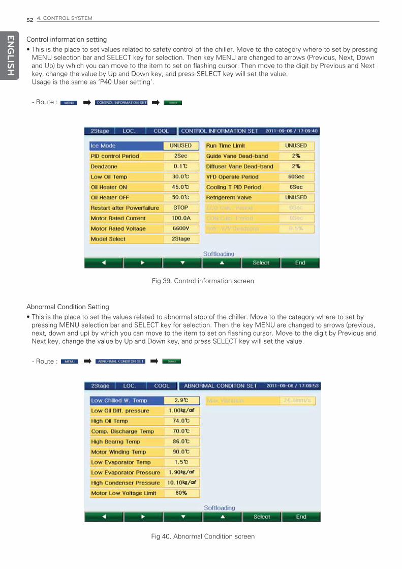
ENG
LISH
52 4. CONTROL SYSTEM
Control information setting
• This is the place to set values related to safety control of the chiller. Move to the category where to set by pressingMENU selection bar and SELECT key for selection. Then key MENU are changed to arrows (Previous, Next, Downand Up) by which you can move to the item to set on flashing cursor. Then move to the digit by Previous and Nextkey, change the value by Up and Down key, and press SELECT key will set the value.Usage is the same as ‘P40 User setting’.
- Route :
Fig 39. Control information screen
Abnormal Condition Setting
• This is the place to set the values related to abnormal stop of the chiller. Move to the category where to set bypressing MENU selection bar and SELECT key for selection. Then the key MENU are changed to arrows (previous,next, down and up) by which you can move to the item to set on flashing cursor. Move to the digit by Previous andNext key, change the value by Up and Down key, and press SELECT key will set the value.
- Route :
Fig 40. Abnormal Condition screen

ENG
LISH
4. CONTROL SYSTEM 53
1) Chilled Water Temperature Low Limit
It sets the lower limit value to prevent freezing of the chilled water.
If the chilled water outlet temperature is lower than the set value of ‘chilled water outlet temperature lower limit’,chiller will abnormally stop.
2) Oil Differential Pressure Low Limit
It sets the lower limit of the oil differential pressure.
If the oil differential pressure during the chiller operation becomes lower than the set value, chiller will abnormallystop.
3) Oil Temperature High Limit
It sets the upper limit of the oil temperature
If the chiller oil temperature is higher than the set value, chiller will abnormally stop.
4) Compressor Discharge Temperature High Limit
It sets the upper limit of the compressor discharge temperature
If the compressor discharge temperature during the chiller operation becomes bigger than the set value, chiller willabnormally stop.
5) Bearing Temperature High Limit
It sets the upper limit of the bearing temperature
If the bearing temperature goes above the set value, chiller will abnormally stop.
6) Motor Winding Temperature High Limit
It is the menu to set upper limit temperature of motor winding.
If any one of the motor winding R, S, or T phase temperature exceeds the set value, it will stop the chiller alarmingAbnormal.
7) Evaporator Refrigerant Temperature Low Limit
It is the place to set the lower limit of the evaporator temperature.
If the evaporator temperature during the chiller operation becomes lower than the set value, chiller will abnormallystop.
8) Evaporator Pressure Low Limit
It sets the lower limit of the evaporator pressure.
If the evaporator pressure during the chiller operation becomes lower than the set value, chiller will abnormallystop.
9) Condenser Pressure High
It sets the upper limit of the condenser pressure.
If the condenser pressure during the chiller operation becomes higher than the set value, chiller will abnormallystop.
10) Motor Low Voltage Limit
It is the menu to set the rated voltage of the compressor motor.
Based on this value, motor voltage lower limit control will be performed.
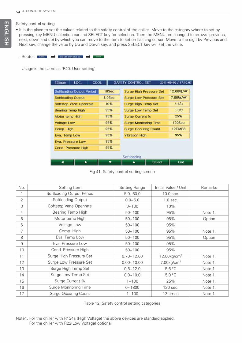
ENG
LISH
54 4. CONTROL SYSTEM
Safety control setting
• It is the place to set the values related to the safety control of the chiller. Move to the category where to set bypressing key MENU selection bar and SELECT key for selection. Then the MENU are changed to arrows (previous,next, down and up) by which you can move to the item to set on flashing cursor. Move to the digit by Previous andNext key, change the value by Up and Down key, and press SELECT key will set the value.
- Route :
Usage is the same as ‘P40. User setting’.
Fig 41. Safety control setting screen
Table 12. Safety control setting categories
No. Setting Item Setting Range Initial Value / Unit Remarks
1 5.0~60.0 10.0 sec.
2 0.0~5.0 1.0 sec.
3 0~100 10%
4 50~100 95% Note 1.
5 50~100 95% Option
6 50~100 95%
7 50~100 95% Note 1.
8 50~100 95% Option
9 50~100 95%
10 50~100 95%
11 0.70~12.00 12.00kg/cm2 Note 1.
12 0.00~10.00 7.00kg/cm2 Note 1.
13 0.5~12.0 5.6 °C Note 1.
14 0.0~10.0 5.0 °C Note 1.
15 1~100 25% Note 1.
16 0~1800 120 sec. Note 1.
17 1~100 12 times Note 1.
Note1. For the chiller with R134a (High Voltage) the above devices are standard applied.For the chiller with R22(Low Voltage) optional
Softloading Output Period
Softloading Output
Softstop Vane Openrate
Bearing Temp High
Motor temp High
Voltage Low
Comp. High
Eva. Temp Low
Eva. Pressure Low
Cond. Pressure High
Surge High Pressure Set
Surge Low Pressure Set
Surge High Temp Set
Surge Low Temp Set
Surge Current %
Surge Monitoring Time
Surge Occuring Count

ENG
LISH
4. CONTROL SYSTEM 55
Timer setting
• It is the place to set the values related to timer required for chiller operation. Move to the category where to set bypressing MENU selection bar and SELECT key for selection. Then the MENU are changed to arrows (previous,next, down and up) by which you can move to the item to set on flashing cursor. Move to the digit by Previous andNext key, change the value by Up and Down key, and press SELECT key will set the value.
- Route :
Usage is the same as ‘P40. User setting’.
Figure 42. Timer setting screen
Table 13. Timer setting
No. Setting Item Setting Range Initial Value/Unit
1 1~1800 300 sec.
2 1~60 5 sec.
3 1~1800 30 sec.
4 1~60 2 sec.
5 30~600 180 sec.
6 30~600 300 sec.
7 1~60 10 sec.
8 30~600 120 sec.
9 30~600 120 sec.
10 0~600 30 sec.
11 10~60 20 sec.
12 10~3600 1800 sec.
Chilled W. Pump Stop
Cond. W. Pump Run
Cond. W. Pump Stop
Flow Chattering ignore
Oil Pump Run
Oil Pump Stop
Oil Pressure Check
Start Vane Close
Stop Vane Close
Vane Open Delay
Comp. Motor Run Check
Anti-Recycle
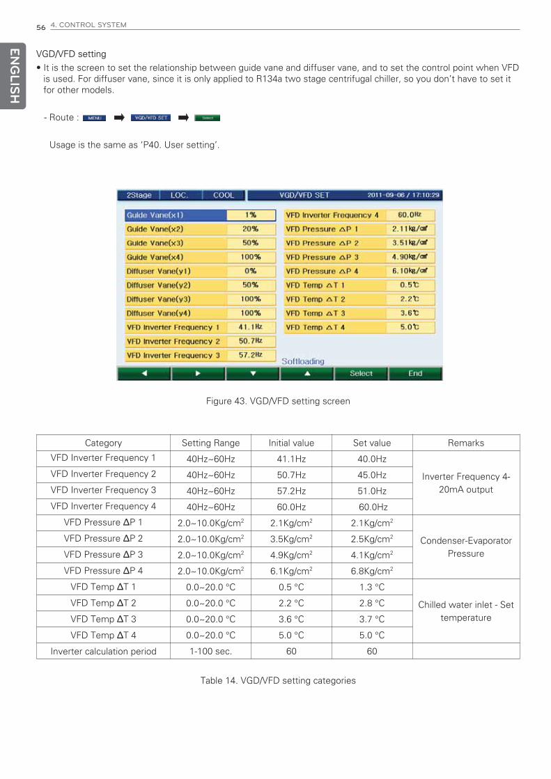
ENG
LISH
56 4. CONTROL SYSTEM
VGD/VFD setting
• It is the screen to set the relationship between guide vane and diffuser vane, and to set the control point when VFDis used. For diffuser vane, since it is only applied to R134a two stage centrifugal chiller, so you don’t have to set itfor other models.
- Route :
Usage is the same as ‘P40. User setting’.
Figure 43. VGD/VFD setting screen
Table 14. VGD/VFD setting categories
Category Setting Range Initial value Set value Remarks
40Hz~60Hz 41.1Hz 40.0Hz
Inverter Frequency 4-20mA output
40Hz~60Hz 50.7Hz 45.0Hz
40Hz~60Hz 57.2Hz 51.0Hz
40Hz~60Hz 60.0Hz 60.0Hz
2.0~10.0Kg/cm2 2.1Kg/cm2 2.1Kg/cm2
Condenser-EvaporatorPressure
2.0~10.0Kg/cm2 3.5Kg/cm2 2.5Kg/cm2
2.0~10.0Kg/cm2 4.9Kg/cm2 4.1Kg/cm2
2.0~10.0Kg/cm2 6.1Kg/cm2 6.8Kg/cm2
0.0~20.0 °C 0.5 °C 1.3 °C
Chilled water inlet - Settemperature
0.0~20.0 °C 2.2 °C 2.8 °C
0.0~20.0 °C 3.6 °C 3.7 °C
0.0~20.0 °C 5.0 °C 5.0 °C
1-100 sec. 60 60
VFD Inverter Frequency 1
VFD Inverter Frequency 2
VFD Inverter Frequency 3
VFD Inverter Frequency 4
VFD Pressure ΔP 1
VFD Pressure ΔP 2
VFD Pressure ΔP 3
VFD Pressure ΔP 4
VFD Temp ΔT 1
VFD Temp ΔT 2
VFD Temp ΔT 3
VFD Temp ΔT 4
Inverter calculation period
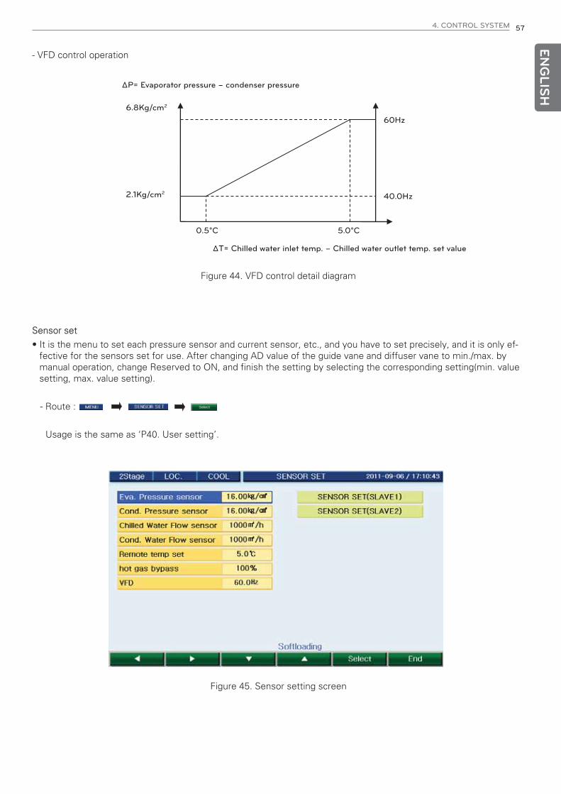
ENG
LISH
4. CONTROL SYSTEM 57
- VFD control operation
ΔP= Evaporator pressure – condenser pressure
ΔT= Chilled water inlet temp. – Chilled water outlet temp. set value
6.8Kg/cm2
2.1Kg/cm2
0.5°C
60Hz
40.0Hz
5.0°C
Figure 44. VFD control detail diagram
Sensor set
• It is the menu to set each pressure sensor and current sensor, etc., and you have to set precisely, and it is only ef-fective for the sensors set for use. After changing AD value of the guide vane and diffuser vane to min./max. bymanual operation, change Reserved to ON, and finish the setting by selecting the corresponding setting(min. valuesetting, max. value setting).
- Route :
Usage is the same as ‘P40. User setting’.
Figure 45. Sensor setting screen

ENG
LISH
58 4. CONTROL SYSTEM
LOGDATA
• It is the menu to check operation data, temperature control graph, start/stop information, etc. stored in the con-troller of the chiller. You can also check the information of the total accumulated number of operations (number ofstart/stop) and total accumulated operation time of the chiller and main subsidiary devices.
- Route :
11
11
Figure 46. Chiller history screen
1) Run Information
- Route :
11
11
Fig 47. Chiller operation information screen
You can check up to 1~300 data using ① button.

ENG
LISH
4. CONTROL SYSTEM 59
2) Run Data
- Route :
1
1
1
1
Fig 48. Operation history information screen
3) Error Data
- Route :
1
1
111
12
Fig 49. Error history information screen
You can check up to 1~300 data using ① button.
You can select error history help using ② button.

ENG
LISH
60 4. CONTROL SYSTEM
4) Help Feature• It displays the help message about the errors and cautions. If Help key is pressed on the error and caution screen,
the help message for the corresponding message is displayed on the help screen. Previous key will show the helpmessage of the previous numbered and Next key for the next numbered help message.
- Route :
Fig 50. Help function screen
5) Print
- Route :
Fig 51. Print function screen
- User set print: It prints the user set page.
- System set print: It prints the current system set information.
- Run information print: It prints from start to end page for run information. (1~300 EA.)
• Auto print: Print with regular time interval.
• Print mode: “1”– All data, “2”– only unit (used by start-up)
- Run data print: It prints from start to end page for run data. (1~300 EA.)
- Error log Print: It prints from start to end page for error data. (1~300 EA.)

ENG
LISH
4. CONTROL SYSTEM 61
6) Graph
- Route :
22
11
22
11
Fig 52. Data graph screen
Use ①buttons to move and select the corresponding data graph display category.
Activated data will be displayed as reversed at ②.

ENG
LISH
62 4. CONTROL SYSTEM
Vane
It is to open and close thee vane (guide vane) manually from the menu. It is composed to be operated as the same asthe control valve automatic/manual conversion key and open/close key on the front of the display device. When it isstopped, forced closing is operated by control logic, so manual open does not work.
Oil pump
It is to operate the oil pump manually from the menu. It is composed to be operated as the same as the oil pump au-tomatic/manual conversion key and start/stop key on the front of the display device. Manual stop does not work toprotect chiller during the operation.
Manual operation screen
Fig 53. Manual operation screen

ENG
LISH
4. CONTROL SYSTEM 63
h Min. Run/Stop pulse maintaining time: maintains for at least 2 sec.
Remote Run/Stop signal connection
• No voltage and continuous contact (2 wire connection)
Remote control signal and the connection
Chiller control panel
Operation signal
Chiller status
ONOFF
RUNStop
101 RUN
DIC1
User control panel
Fig 54. Remote control signal detail diagram
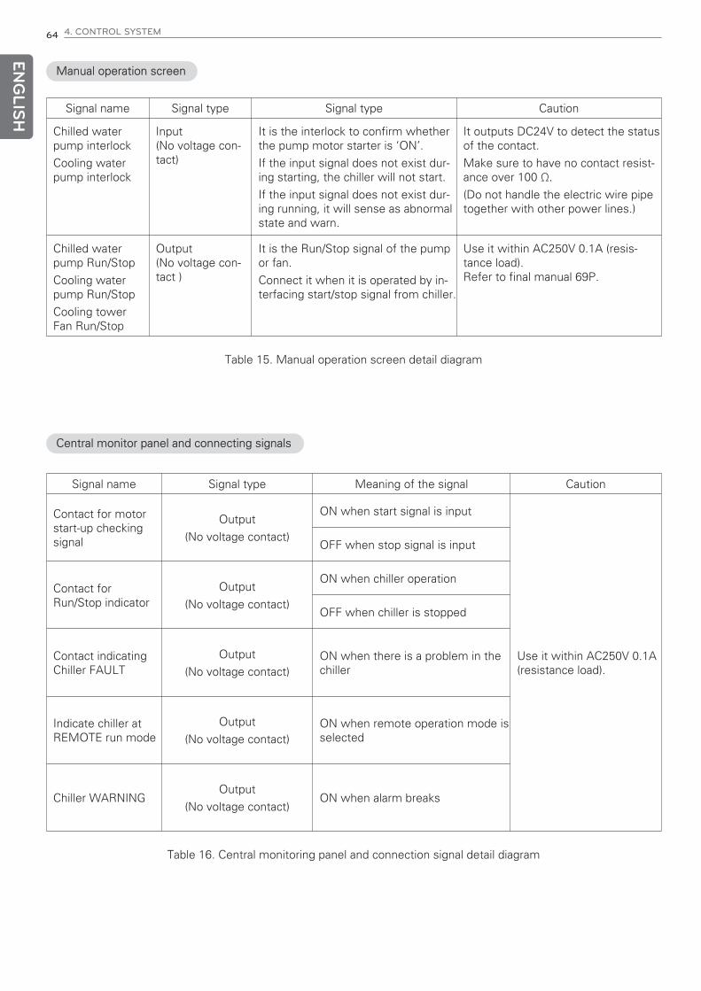
ENG
LISH
64 4. CONTROL SYSTEM
Manual operation screen
Signal name Signal type Signal type Caution
Chilled waterpump interlock
Cooling waterpump interlock
Input(No voltage con-tact)
It is the interlock to confirm whetherthe pump motor starter is ‘ON’.
If the input signal does not exist dur-ing starting, the chiller will not start.
If the input signal does not exist dur-ing running, it will sense as abnormalstate and warn.
It outputs DC24V to detect the statusof the contact.
Make sure to have no contact resist-ance over 100 Ω.
(Do not handle the electric wire pipetogether with other power lines.)
Chilled waterpump Run/Stop
Cooling waterpump Run/Stop
Cooling towerFan Run/Stop
Output(No voltage con-tact )
It is the Run/Stop signal of the pumpor fan.
Connect it when it is operated by in-terfacing start/stop signal from chiller.
Use it within AC250V 0.1A (resis-tance load).Refer to final manual 69P.
Central monitor panel and connecting signals
Table 15. Manual operation screen detail diagram
Table 16. Central monitoring panel and connection signal detail diagram
Signal name Signal type Meaning of the signal Caution
Contact for motorstart-up checkingsignal
Output
(No voltage contact)
ON when start signal is input
Use it within AC250V 0.1A(resistance load).
OFF when stop signal is input
Contact forRun/Stop indicator
Output
(No voltage contact)
ON when chiller operation
OFF when chiller is stopped
Contact indicatingChiller FAULT
Output
(No voltage contact)ON when there is a problem in thechiller
Indicate chiller atREMOTE run mode
Output
(No voltage contact)ON when remote operation mode isselected
Chiller WARNINGOutput
(No voltage contact)ON when alarm breaks

ENG
LISH
4. CONTROL SYSTEM 65
1) Thorough preparation
Check first aid method, arrangements around the work site, and safety of the facility and machine.
2) Review with circuit diagram
If power system receives power from another source, check the powers to the panels, power application to the1st side of the circuit breaker and proper grounding.
3) Contact
Check if you can closely contact with the relevant departments.
4) Check for no voltage state and safety measures
During the inspection of the main circuit, please review the following issues for safety.
- Open the related breaker and disconnecting switch and make no voltage on the main circuit.
- Check no voltage status with electroscope, and make groundings where necessary.
- Open circuit breakers and disconnect switches and attach a warning sign board "Checking".
- Use the disconnection switch operation after power is disconnected.
- Especially when the power is supplied via another source such as consumer side power distribution panel, auto-matic control, MCC panel, etc., take the above c) and d) actions to the other side switches.
5) Cautions for current and voltage
Discharge the remaining charges and conduct grounding before you inspect the condenser and cable connectionpart.
6) Prevention from wrong operation
Disconnect the power and attach a caution mark.
7) Prepare insulated protection equipment
Wear safety protection equipment such as insulated gloves, safety helmet, insulated boots, and safety apparel fitfor the rated voltage.
8) Measures against rat, insects, etc.
Take countermeasures to prevent rat, insects, snakes, etc from entering into the panel.
Check list before inspection

ENG
LISH
66 4. CONTROL SYSTEM
1) Final check
- Check whether any staff is inside the panel.
- Check whether the removal of the temporary building for inspection is being delayed.
- Make sure not to forget bolt tightening work.
- Check if any tools are left.
- Check whether rat or insects have been in.
2) Recording of the inspections
When inspection, make sure to record the summary of the inspections and repairs, status of the failure and date,etc. to utilize them as the reference for the next inspection.
List to check after maintenance
! CAUTION
Establish the daily inspections to be able to check the load of the machine in operation, operation time, opera-tion environment, etc.
The inspection period stated in this manual is a general inspection period. Therefore establish the inspectionplan according to the load status of the machine and usage frequency.
Do not test the insulation resistance on the 2nd side of the transformer for controller or control power.
Do not test the insulation resistance on the parts like sensor, switch, etc. which are connected to the controller.

ENG
LISH
4. CONTROL SYSTEM 67
General Inspection items
Inspec-tion
Inspectioncategories
Inspection items CriteriaDaily 1 year 2 years
All
Ambientenviron-
ment
Is there any dust?Is the ambient temperature and humidity ade-quate?Is there any abnormal vibration?
Refer to Chapter 1. Environ-mental conditions
Equipment Is there any vibration or noise? No abnormality
Maincircuit/ Con-
trolcircuit
Input volt-age
Is the main circuit voltage normal?Is the main circuit voltage normal?
Refer to Chapter 1. Environ-ment
Insulationresistance
test
Disconnect all power before testing insulationresistance.Insulation between the transformer 1st side andgrounding bus-bar.When measuring the resistance, disassemble allgrounding wires connected to grounding bus–bar.
*Low voltage (600Vac orless) DC 500V class mega,it shall be 5MΩ or more.*High voltage (exceeding
600Vac, 7000Vac)DC 1000V class mega, itshall be 30MΩ or more.
Overheating Is there any trace of overheating in each component? No abnormality
Fixed parts Is there any missing fixed parts? No abnormality
Conduc-tor/wire
Is there any contamination of conductor?Is there any damage in the wires?
No abnormality
Terminal Is there any damaged part? No abnormality
Relay/contactor
Is there any oscillation during operation?Is there any damage on the connector?
No abnormality
Spaceheater
Is there any color change of the heater compo-nent in starter panel?
No abnormality
Sensor &switch
Is there any disconnection or short circuit?Is there any damage in the contact part?
No abnormality
Grounding
Is there any rust on the connection part?Is there any damage in the grounding conductor?Is there any noise in the grounding system?Note: Grounding resistance shall meet the require-ments of the related codes and standards.
No abnormality
Phase advancecapacitor
Is the expansion under the limit? No abnormality
Cooling fan Is there any abnormal noise? (Control Panel) No abnormality
Con-trol
func-tion
Safety func-tion
Is the safety function in normal operation?Is the start-up sequence normally carried out?Is the stop sequence normally carried out?Is the temp. regulation within the specification?
Normal control
Dis-play
Analogvalue
Is the displayed value correct? No abnormality
IndicationLamp
Is the indication lamp displayed with the normalbrightness?
No abnormality
Table 16. General Inspection Items

ENG
LISH
68 4. CONTROL SYSTEM
4-6. Startup and Control sequence
Signal Flowchart
Signal flowchart of the centrifugal chiller
Run/StopChillerRun/Stop
Run/stopsignal
Chilled water pump on
Cooling water pump on
Timer > 5sec*
Comp. Stop(2M signal
OPEN)
Stop Condition(Satisfaction)
Vane opening < 10%Vane Close S/W ONVane Stop Timer > 240sec*
OR Condition
Oil temp. > 30°C*Vane close S/W ONCooling Water Temperature > (Set Value + 2°C)*Restarting prevention timer OFF
AND Condition
STOP
No
RUN
Yes
Yes
Yes
Yes
Yes
Yes
Yes
Yes
Yes
Yes
Yes
Yes
No
No
No
No
Check Flow amount
Oil circulation timer > 3 min*
Starting Condition(Satisfaction)
CR (Closing Relay) ON
Chiller RUN(Operation/Safety Control) Abnormal
Comp. Run Complete signal (2M)(within 20sec*)
Standby untilsatisfaction Chilled Water Pump Stop
Oil Timer > 5min*
Oil Pump Stop
Chiller Stop
Timer=0 for oil circulationpump before start-up
Comp. Stop (CR OFF)AND
Cooling water Pump Stop
Timer > 30sec*
Figure 55. Signal flowchart
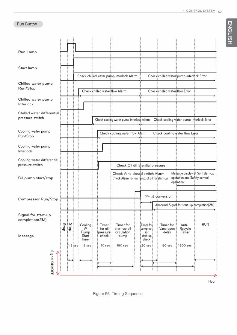
ENG
LISH
4. CONTROL SYSTEM 69
Run Button
Run Lamp
Start lamp
Chilled water pumpRun/Stop
Chilled water pumpInterlock
Chilled water differentialpressure switch
Cooling water pumpRun/Stop
Cooling water pumpInterlock
Cooling water differentialpressure switch
Oil pump start/stop
Compressor Run/Stop
Signal for start-upcompletion(2M)
Message
1.5 sec 5 sec 10 sec 20 sec 60 sec180 sec 1800 sec
Stop
Stop
Signal O
N/O
FF
Check Oil differential pressure
Check Vane closed switch AlarmCheck Alarm for low temp. of oil for start-up
conversion
Abnormal Signal for start-up completion(2M)
Message display of Soft start-upoperation and Safety controloperation
Check cooling water pump interlock Alarm
Check cooling water flow Alarm Check cooling water flow Error
Check cooling water pump Interlock Error
Check chilled water pump interlock Alarm
Check chilled water flow Alarm Check chilled water flow Error
Check chilled water pump interlock Error
RUN
Hour
Cooling W.
Pump Start Timer
Timer for oil
pressure check
Timer for start-up oil circulation
pump
Timer for compres-
sor start-up check
Timer for Vane open
delay
Anti-Recycle Timer
Figure 56. Timing Sequence
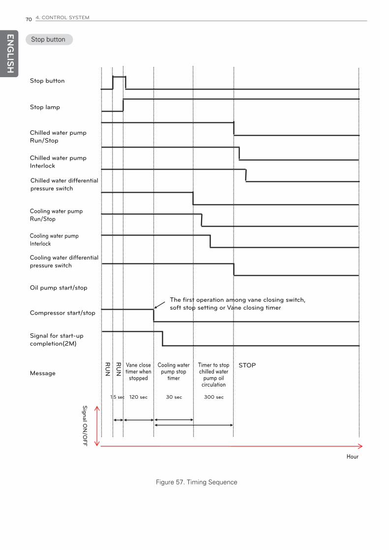
ENG
LISH
70 4. CONTROL SYSTEM
Stop button
Stop button
Stop lamp
Chilled water pumpRun/Stop
Chilled water pumpInterlock
Chilled water differentialpressure switch
Cooling water pumpRun/Stop
Cooling water pumpInterlock
Cooling water differentialpressure switch
Oil pump start/stop
Compressor start/stop
The first operation among vane closing switch,soft stop setting or Vane closing timer
Signal for start-upcompletion(2M)
Message
Signal O
N/O
FF
Hour
1.5 sec 120 sec 30 sec 300 sec
RU
N
STOP
RU
N
Vane close timer when
stopped
Cooling water pump stop
timer
Timer to stop chilled water
pump oil circulation
Figure 57. Timing Sequence

ENG
LISH
4. CONTROL SYSTEM 71
4-7. Product protection function
Protection Logic
Classifica-tion
Content Cause Operation Condition
SensorTemperature, pressure and currentsensors abnormality
Detected abnormality from temper-ature, pressure or current sensors
Chiller stops Abnormal
Interlock
Chilled water pump interlock ErrorDetected Error with pump interlockduring operation
Chiller stops Abnormal
Cooling water Pump Interlock ErrorDetected Pump interlock problemwas detected during operation
Chiller stops Abnormal
Chilled water low-flow abnormalDetected Flow interlock problemwas detected during operation
Chiller stops Abnormal
Cooling water Flow Low ErrorDetected Flow interlock problemwas detected during operation
Chiller stops Abnormal
Tempera-ture andpressure
Control of High temperature of OilError
Detected High temperature of Oil Chiller stops Abnormal
Error of Condenser Pressure HighError
Detected Condenser Pressure High Chiller stops Abnormal
Evaporator Low Pressure Error Detected Evaporator Pressure Low Chiller stops Abnormal
Evaporator Refrigerant PreventionError
Detected Evaporator RefrigerantTemperature Low Error
Chiller stops Abnormal
Compressor discharge Tempera-ture High error
Detected Compressor dischargetemperature High Error
Chiller stops Abnormal
Motor winding temperature HighError
Detected Motor winding tempera-ture High Error
Chiller stops Abnormal
Bearing high temperature problemDetected Bearing high Tempera-ture Error
Chiller stops Abnormal
Chilled water temperature Lowerror
Detected chilled water outlet tem-perature Low error
Chiller stops Abnormal
Surge oc-curred
Compressor Surge current ErrorDetected Compressor Surge cur-rent Error
Chiller stops Abnormal
Voltage Detected Low Voltage ErrorDetected Compressor motor Volt-age Low Error
Chiller stops Abnormal
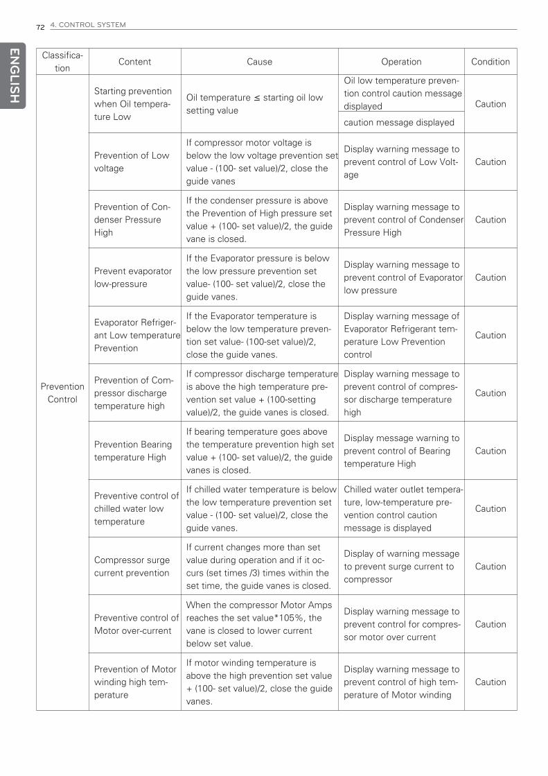
ENG
LISH
72 4. CONTROL SYSTEM
Classifica-tion
Content Cause Operation Condition
PreventionControl
Starting preventionwhen Oil tempera-ture Low
Oil temperature ≤ starting oil lowsetting value
Oil low temperature preven-tion control caution messagedisplayed Caution
caution message displayed
Prevention of Lowvoltage
If compressor motor voltage isbelow the low voltage prevention setvalue - (100- set value)/2, close theguide vanes
Display warning message toprevent control of Low Volt-age
Caution
Prevention of Con-denser PressureHigh
If the condenser pressure is abovethe Prevention of High pressure setvalue + (100- set value)/2, the guidevane is closed.
Display warning message toprevent control of CondenserPressure High
Caution
Prevent evaporatorlow-pressure
If the Evaporator pressure is belowthe low pressure prevention setvalue- (100- set value)/2, close theguide vanes.
Display warning message toprevent control of Evaporatorlow pressure
Caution
Evaporator Refriger-ant Low temperaturePrevention
If the Evaporator temperature isbelow the low temperature preven-tion set value- (100-set value)/2,close the guide vanes.
Display warning message ofEvaporator Refrigerant tem-perature Low Preventioncontrol
Caution
Prevention of Com-pressor dischargetemperature high
If compressor discharge temperatureis above the high temperature pre-vention set value + (100-settingvalue)/2, the guide vanes is closed.
Display warning message toprevent control of compres-sor discharge temperaturehigh
Caution
Prevention Bearingtemperature High
If bearing temperature goes abovethe temperature prevention high setvalue + (100- set value)/2, the guidevanes is closed.
Display message warning toprevent control of Bearingtemperature High
Caution
Preventive control ofchilled water lowtemperature
If chilled water temperature is belowthe low temperature prevention setvalue - (100- set value)/2, close theguide vanes.
Chilled water outlet tempera-ture, low-temperature pre-vention control cautionmessage is displayed
Caution
Compressor surgecurrent prevention
If current changes more than setvalue during operation and if it oc-curs (set times /3) times within theset time, the guide vanes is closed.
Display of warning messageto prevent surge current tocompressor
Caution
Preventive control ofMotor over-current
When the compressor Motor Ampsreaches the set value*105%, thevane is closed to lower currentbelow set value.
Display warning message toprevent control for compres-sor motor over current
Caution
Prevention of Motorwinding high tem-perature
If motor winding temperature isabove the high prevention set value+ (100- set value)/2, close the guidevanes.
Display warning message toprevent control of high tem-perature of Motor winding
Caution
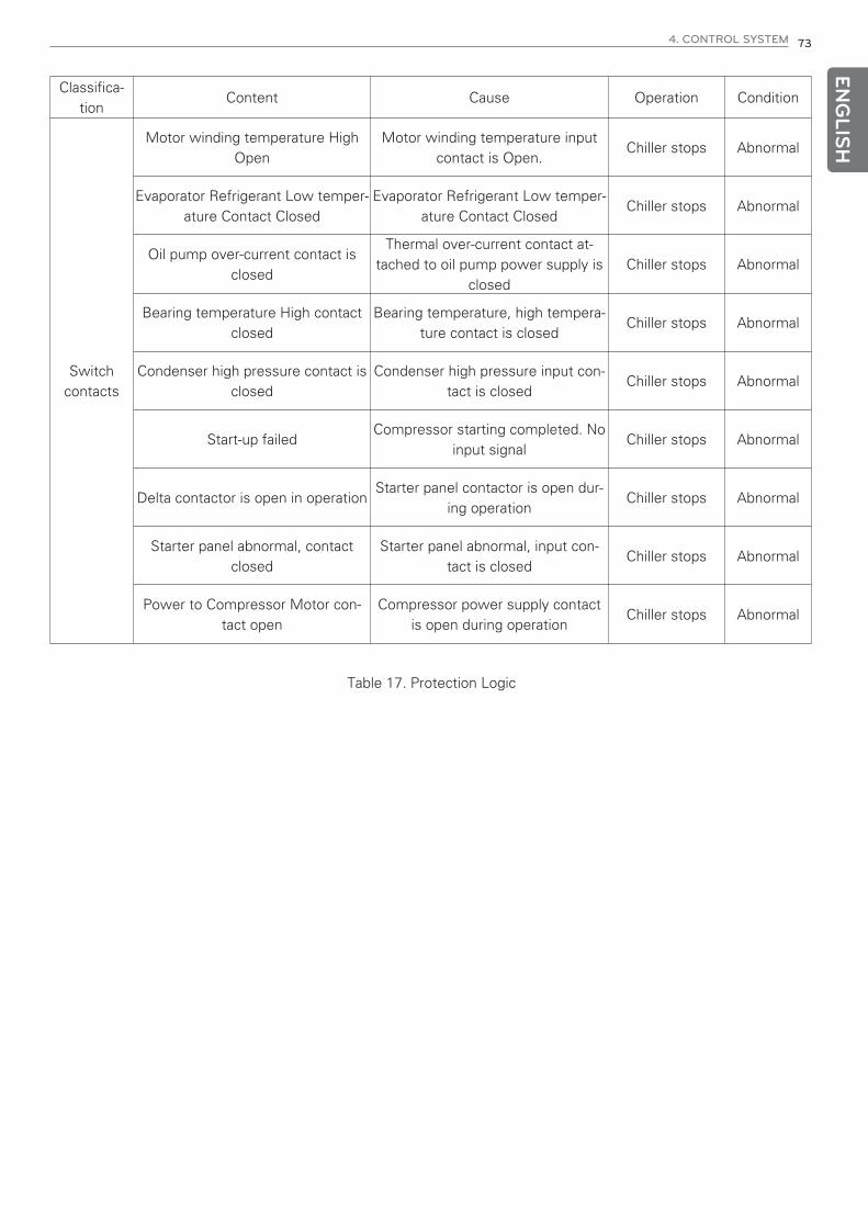
ENG
LISH
4. CONTROL SYSTEM 73
Classifica-tion
Content Cause Operation Condition
Switchcontacts
Motor winding temperature HighOpen
Motor winding temperature inputcontact is Open.
Chiller stops Abnormal
Evaporator Refrigerant Low temper-ature Contact Closed
Evaporator Refrigerant Low temper-ature Contact Closed
Chiller stops Abnormal
Oil pump over-current contact isclosed
Thermal over-current contact at-tached to oil pump power supply is
closedChiller stops Abnormal
Bearing temperature High contactclosed
Bearing temperature, high tempera-ture contact is closed
Chiller stops Abnormal
Condenser high pressure contact isclosed
Condenser high pressure input con-tact is closed
Chiller stops Abnormal
Start-up failedCompressor starting completed. No
input signalChiller stops Abnormal
Delta contactor is open in operation Starter panel contactor is open dur-
ing operationChiller stops Abnormal
Starter panel abnormal, contactclosed
Starter panel abnormal, input con-tact is closed
Chiller stops Abnormal
Power to Compressor Motor con-tact open
Compressor power supply contactis open during operation
Chiller stops Abnormal
Table 17. Protection Logic

ENG
LISH
74 5. START-UP
5. START-UP5-1. Delivery and Installation Check
From Receipt, Installation to Startup
Air tightness test
Vacuuming test
Oil charging
Charge Refrigerant
Lubrication systemoperation adjustment
Function test forstarter and
controller panel
Function testfor safety devices
Check before start-up
Check beforeand after start-up
Run chilled water pump/Run cooling water pump
ChargingNitrogen gas
If a month or moreleft until operation,
Dissatisfaction
Wiring constructionbetween starter paneland control panel.(The order can be changed.)
Installation of Foundation(foundation panel)
Receipt and Installation
Insulation resistance test

ENG
LISH
5. START-UP 75
Stop
Load operationand operation setting
Record run data
Water quality analysis forcooling and chilled water
Operation guide
Finishing
Fig 58. From receipt to Startup
Selecting a location
• If the chiller has to be installed near heat generating devices, keep distances more than 5 meters from boilers andhot-air blowers, and more than 2 meters from other heat generating devices.
• Choose a well-ventilated place and avoid place with high temperature.
• Choose a place with less humid.
• Provide ample space for service (for control and maintenance of pipes and tubes)
Foundation
• Build the foundation to withstand the concentrated heavy weight of the chiller.
• The foundation should be higher than the surface of the water, and install the drainage around.
• Be sure to install the drain pipe to the drainage hole.
Receipt and Installation
• The chiller should be installed evenly leveled to the ground.
• Install the chiller on a foundation with flat support surfaces, level within ±1mm with the manufacturer-supplied iso-lation pad assemblies under the unit.
• Make sure the foundation surface is flat and leveled within ±1mm using a level, and if not, readjust itwithin: ±1mm, using spacers.

ENG
LISH
76 5. START-UP
5-2. Preparation for start-up
Preparation for start-up
Air tightness test
Vacuuming test
Oil charge
Refrigerant charge
Insulation resistance test
Lubrication systemoperation adjustment
Function test ofstarter and
controller panel
Check safety devices
• It is called start-up run that the first run after receipt and installation or the run after long-term stoppage (over 1month) before the regular operation of the chiller.
• Preparation for start-up is the maintenance and repairing work at least once a year after installation\, which is a verybasic and important task.
Checking the leak parts
It is recommended to perform leakage test following the steps in Fig 58.Refer to the temperature and pressure values of the refrigerant in Table 18.
Fig. 59. Preparation procedure for start-up

ENG
LISH
5. START-UP 77
Leakage Inspection
• The condition that requires the leak test
- After the chiller is disassembled and repaired,
- If the nitrogen's pressure charged in factory was lower during the transportation before the initial start-up:
• Weak Points for leak:
- Parts where the gasket is used
- Nut tighten part, bolt and nut
- Copper tube connecting part
- Sight-glass welded part
- Compressor motor terminal
Inspection method
1) Charge the nitrogen in order until the internal pressure of the machine reaches 2 kg/cm2, 5 kg/cm2, 9~9.5 kg/cm2.
2) Perform the soapy water test on every connecting part.
3) If the inspected pressure lasts for more than 30 min., prepare to do the soapy water test for smaller parts.
4) Mark the leaking point.
5) Eject the inner pressure of the machine.
6) Fix all the leaking points.
7) Do leak test again on the repaired points
8) After performing the large leaking test, increase the inner pressure up to the value of 9~9.5 kg/cm2.
9) Do the small leak test and fix them all.
10) After the leak test Is finished, exhaust the nitrogen gas very carefully.
* Please close the valve of evaporator, as when you increase the pressure inside of the chiller, the relief valve on theevaporator may get open.
Note: Open the relief valve on the condenser by1.05 Mpa (10.71 kg/cm2).The relief valve on the evaporator open at 0.99 Mpa (10.1 kg/cm2)

ENG
LISH
78 5. START-UP
Temperature °C Pressure 1kg/cm2 Temperature °C Pressure 1kg/cm2 Temperature °C Pressure 1kg/cm2
-26.18 0 15 3.9517 51 12.740
-20 0.3255 16 4.1136 52 13.087
-19 0.3850 17 4.2793 53 13.400
-18 0.4465 18 4.4491 54 13.800
-17 0.5101 19 4.6230 55 14.167
-16 0.5758 20 4.6230 56 14.540
-15 0.6437 21 4.9932 57 14.921
-14 0.7138 22 5.1697 58 15.308
-13 0.7862 23 5.3605 59 15.703
-12 0.8610 24 5.5558 60 16.104
-11 0.9381 25 5.7555 61 16.513
-10 1.0176 26 5.9597 62 16.929
-9 1.0996 27 6.1685 63 17.353
-8 1.1841 28 6.3819 64 17.784
-7 1.2713 29 6.6001 65 18.223
-6 1.3610 30 6.8231 66 18.670
-5 1.4535 31 7.0510 67 19.124
-4 1.5486 32 7.2838 68 19.587
-3 1.6466 33 7.5216 69 20.057
-2 1.7474 34 7.7644 70 20.536
-1 1.8512 35 8.0124 71 21.023
0 1.9579 36 8.2657 72 21.518
1 2.0675 37 8.5242 73 22.023
2 2.1803 38 8.788 74 22.535
3 2.2962 39 9.0578 75 23.057
4 2.4153 40 9.3318 76 23.587
5 2.5376 41 9.6128 77 24.127
6 2.6632 42 9.8988 78 24.676
7 2.7922 43 10.190 79 25.234
8 2.9246 44 10.488 80 25.802
9 3.0604 45 10.791 81 26.379
10 3.1998 46 11.101 82 26.966
11 3.3428 47 11.416 83 27.563
12 3.4894 48 11.738 84 28.171
13 3.6397 49 12.066 85 28.788
14 3.7938 50 12.400 86 29.417
Table 18. HFC-134a Temperature / Pressure

ENG
LISH
5. START-UP 79
Vacuum Dry & Vacuum Test
• The vacuum dry work has to be taken to eliminate the humidity when the machine is exposed to the atmosphericair for a long time or it is indicated that the moisture got into the machine or complete pressure loss of refrigeranthappened due to refrigerant leak.
! WARNING
Do not operated the compressor motor or the oil pump motor, and do not take any insulation resistance testwhen performing the vacuum dry work.
Even instant rotation for rotation check-up can damage the electrical insulation and cause huge damage.
• Generally the vacuum dry work is performed at a room temperature. The higher the room temperature is, the fasterthe vacuum dry performance will be done. Stronger vacuum quality is required to evaporate the moist in the envi-ronment of lower room temperature. The vacuum dry working procedure is as follows.
1) Connect the high capacity vacuum pump (Approximately above 120 LPM) to the refrigerant charge valve. The length of the pipe from the pump to the machine should be as short as possible and the diameter of the pipeas big as possible for minimum gas flow resistance.
2) To measure the vacuum, if the pressure gauge is installed or pressure value from MICOM is available, the pres-sure gauge may be used.
3) When vacuuming work, open all the valves except the valves connected to external.
4) Allow approximately 2 hours of additional vacuum pump operation, if the surrounding temperature of the ma-chine is above 15.6 °C, and while the vacuum pump is operated if the manometer is indicating 756mmHg.If the internal pressure of the chiller is kept below 756 mmHg, the accumulated moist in the machine would befrozen and then this ice is evaporated more slowly than in normal condition, which leads to a delay of the vac-uum dry work. If there is hot water at this situation, let the evaporator and the condenser be flowed by the hotwater and then operate the vacuum pump.
5) Fasten the vacuum pump valve and stop the pump, and then record the vacuum gauge value.When reading the degree of the vacuum while the surrounding temperature varies, it has to be compensated byconverting the temperature change into pressure using below equation.
6) The vacuum dry work is terminated if there is no change in the vacuum gauge value after waiting for 4 hours.The machine is well air-tight if the leak rate is below 0.1 mmHg/h(=0.1 Torr/h). If the vacuum gauge value roseup, repeat step 4) and 5).
7) If the value still changes after several time of vacuum dry work, set the inner machine pressure above9~9.5kg/cm2.G and perform the leak inspection. After fixing the part where it is leaking, redo the vacuum drywork.
△P + (760 + H)x mmHg-273+ t2
t2
273+ t1
t1
H: Internal pressure before the inspection (mmHg)
t1: Surrounding temp. before the inspection (°C)
t2: Surrounding temp. after the inspection (°C)
Table 19. HFC-134a Temperature / Pressure
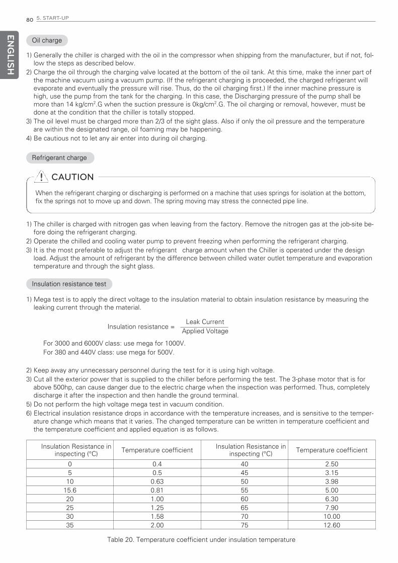
ENG
LISH
80 5. START-UP
Refrigerant charge
1) The chiller is charged with nitrogen gas when leaving from the factory. Remove the nitrogen gas at the job-site be-fore doing the refrigerant charging.
2) Operate the chilled and cooling water pump to prevent freezing when performing the refrigerant charging.3) It is the most preferable to adjust the refrigerant charge amount when the Chiller is operated under the design
load. Adjust the amount of refrigerant by the difference between chilled water outlet temperature and evaporationtemperature and through the sight glass.
Oil charge
1) Generally the chiller is charged with the oil in the compressor when shipping from the manufacturer, but if not, fol-low the steps as described below.
2) Charge the oil through the charging valve located at the bottom of the oil tank. At this time, make the inner part ofthe machine vacuum using a vacuum pump. (If the refrigerant charging is proceeded, the charged refrigerant willevaporate and eventually the pressure will rise. Thus, do the oil charging first.) If the inner machine pressure ishigh, use the pump from the tank for the charging. In this case, the Discharging pressure of the pump shall bemore than 14 kg/cm2.G when the suction pressure is 0kg/cm2.G. The oil charging or removal, however, must bedone at the condition that the chiller is totally stopped.
3) The oil level must be charged more than 2/3 of the sight glass. Also if only the oil pressure and the temperatureare within the designated range, oil foaming may be happening.
4) Be cautious not to let any air enter into during oil charging.
Insulation resistance test
1) Mega test is to apply the direct voltage to the insulation material to obtain insulation resistance by measuring theleaking current through the material.
For 3000 and 6000V class: use mega for 1000V.For 380 and 440V class: use mega for 500V.
2) Keep away any unnecessary personnel during the test for it is using high voltage.3) Cut all the exterior power that is supplied to the chiller before performing the test. The 3-phase motor that is for
above 500hp, can cause danger due to the electric charge when the inspection was performed. Thus, completelydischarge it after the inspection and then handle the ground terminal.
5) Do not perform the high voltage mega test in vacuum condition.6) Electrical insulation resistance drops in accordance with the temperature increases, and is sensitive to the temper-
ature change which means that it varies. The changed temperature can be written in temperature coefficient andthe temperature coefficient and applied equation is as follows.
! CAUTION
When the refrigerant charging or discharging is performed on a machine that uses springs for isolation at the bottom,fix the springs not to move up and down. The spring moving may stress the connected pipe line.
Insulation resistance =Applied Voltage
Leak Current
Insulation Resistance ininspecting (°C) Temperature coefficient Insulation Resistance in
inspecting (°C) Temperature coefficient
0 0.4 40 2.505 0.5 45 3.1510 0.63 50 3.98
15.6 0.81 55 5.0020 1.00 60 6.3025 1.25 65 7.9030 1.58 70 10.0035 2.00 75 12.60
Table 20. Temperature coefficient under insulation temperature

ENG
LISH
5. START-UP 81
7) Other factors that influence the insulation resistance<Pollution of the outer surface of the insulation body> If absorptive and deliquescent materials like acid, chlorideand etc are adhered on the surface of the insulation body, they influence the insulation resistance. Remove the for-eign substances before the inspection. <Condensing Point> If the insulation body temperature is below the sur-rounding temperature's dew point, moisture condensation can be preset on the insulation body surface (especiallyat the crack and the groove) and influence the insulation resistance. The inspection should be taken into actionwhen the insulation body temperature is above the surrounding temperature's dew point. Record the dry bulb andthe wet bulb temperature surrounding air. <Absolute Humidity> Even through the insulation body temperature isabove the dew point, the atmospheric vapor influences insulation resistance. Avoid conduction test at the placewhere the absolute humidity is high present.
8) Apply an electric current for a minute to the spot to be measured up insulation resistance. Read and record thevalue. Apply the inspection standard when the insulation body temperature is 20 °C. (When measured at a differ-ent temperature, use the temperature coefficient and convert the value indicated after a minute.)
9) Taking measures according to insulated condition.
Temp. of insulation body at inspection (°C) Value indicated after a minute Action
Danger Below 2 MΩ Repair or Exchange
Bad Below 50 MΩ Troubleshooting
Re-inspection 50~ 100 MΩ Troubleshooting
Good 100~500 MΩ
Better 500~1000 MΩ
Excellent Above 1000 MΩ
Condition Insulation Absorption Rate
Danger Below 1
Bad Below 1,5
Re-Inspection 1.5~2
Good 2~3
Better 3~4
Excellent Above 4
h Motor that is within the range of "Bad" and "Re-Inspection" at the mega insulation test, must take the POLARIZA-TION INDEX test.
10) Polarization Index Test
Record the indicated value appeared when performing the mega test after a minute and the one after 10 minutes.
If the motor's insulation absorption rate is within the range of "Danger", must be returned or replaced.
If the motor's insulation absorption rate is above the range of "Bad", must be checked additionally after 4 hours ofcareful operation.
11) The following should be recorded when performing the mega test
- Type and voltage of the mega tester
- Connection part of the mega tester
- Surrounding temperature and humidity of the test taking place and the tank's internal pressure in case of her-metic type
- Stoppage period before the inspection
Table 21. Insulation condition
Table 22. Insulation absorption rate status
Insulation Inhaling rate =indicated value after 1 minute
indicated value after 10 minutes

ENG
LISH
82 4. CONTROL SYSTEM
Function test for starter and controller panel
• Test before the Start-up
1. Control Panel and Electric linesCut the power and check the controlling parts and switches for any foreign substances. Also check for normaloperation and terminal connection conditions by handling the switches.
2. VoltageCheck if the voltage indicated at the voltage meter of the starter panel is identical to the rated voltage on thechiller name plate.
3. Chilled and cooling water circulation systemCheck if the chilled and cooling water operation is depicted properly on the display by activating individual pump.
• Control Device Operation Test
1. Check the wiring conditionCheck whether the wiring of power, sensor, etc. are properly connected.Special checking should be taken to power line.
2. Check the display condition after control power inBe more cautious if there is any symptom of getting short for 5 seconds after the power is in.If problem occurs, immediately cut the power and check for abnormality.
3. Check values displayed on the panelCheck if the display indicating sensor values are normal.If the sensor indicates abnormal or error message is displayed, check the connection of the sensors.
4. No power operationWhile the power of the main motor is cut, operate and check whether the operation is normal up to the Starterpanel operation signal. If a message displayed for abnormality, check the part.
• Check of Safety Device
Flow operation test for chilled water and cooling water
- Close the valves located at the pipe of the chilled and cooling water, and check whether the differential pressureswitches for flowing are working properly or not.

ENG
LISH
5. START-UP 83
5-3. Start-up• After the preparation is done for start-up, proceed as follows.
Preparationfor start-up
Power On
Check oil temp.in the oil tank
Check the vane
Oil pump operation
AuxiliaryOperation
Control PanelDisplay Check-up
1) Input power to the control panel and the starter panel,and check the status.
2) Input power to the oil heater 1~2 hours prior to themain operation and make sure that the temperature ofthe oil inside the tank is 30~65°C.
3) After checking the vane opening as 0%, set thevane's operation to "Auto". The vane is to maintain 0%on any condition of "Auto", "Open", "Stop", "Closed"when the chiller stops.
4) Set the oil pump condition of the control panel to"Auto".
5) Activate the chilled water pump. When operating,close the outlet valve, open the air ventilation valveand then open the outlet valve to a small carefully toavoid water hammering so that necessary amount offlow passes through. If water keeps coming out afterthe air discharged through the air outlet, close the airvalve.
6) Activate the cooling water pump. Caution required justas step 5).
7) Check the control panel display if it is working prop-erly. Check if the display is showing local operationmode and chiller's possible operation condition.
Figure 60. Start-up procedure

ENG
LISH
84 5. START-UP
• If the chiller is working under Local Operation Mode, follow the steps as follows. If strange situation is detected,shut down the chiller immediately and follow the "troubleshooting" procedure. For more detailed information, referto the "Check list".
1) Checking the oil pressureWhen the operation button on the control panel ispressed, oil pump will be activated that leads to an in-crease in the oil pressure and if the differential pres-sure between supplying oil to the bearing and theinner tank oil lasts for 120~180 sec. over 0.8 kg/cm2,the compressor motor will be operated.
2) Direction of the compressor motor's rotation.
3) Starting characteristicAt this time, 2 items check-up is needed simultane-ously. Make sure 2 people are working together.
- Direction of the motor's rotationRecord the rotating direction at the counter load partof the motor. If the direction is opposite, stop thechiller and change the two among three phases.
- Starting CharacteristicCheck the starting current, acceleration completiontime as on the "Check List".
4) Check the Operating Current
5) Motor Cooling Status
- Operating CurrentAfter the start-up is done, the vane will be openedgradually and the current increases simultaneously.Operation current should not exceed the rated cur-rent.If exceeds, set it referring to the “capacity controlmodule.”
- Motor Cooling StatusPeriodic physical check-up of the motor surface tem-perature is required while operation.
- Checking the oil tank and the bearing temperatureCheck if the oil tank and the bearing temperature ispreserved at 40~65°C. If not refer to "Trouble Shoot-ing" and "Check List".
6) Checking all sorts of pressure status
7) Checking the operating sound and vibration
8) Chilled-water inlet and outlet temperature
9) Cooling-water inlet and outlet temperature
Fig 61. Start-up procedure (2)
Press the OperationButton
Oil Pump Run
Start the compressormotor
Start-upcompeted
Operating

ENG
LISH
5. START-UP 85
1) In case of load increasingTo preserve the chilled water outlet temperature, the guide vane is opened up to the electromotor rated current.
2) When the load is parallel with present performance of the chillerThe guide vane is stopped at a certain degree of opening.
3) In case of load decreasing
- In opposition to 1), to preserve the chilled water temperature the guide vane is close.
- When the load is continuously decreased, the chilled water outlet temperature will be decreased and the chillerwill be stopped by the function of "Chiller operation/stoppage". If the chilled water outlet temperature increases tothe level of setup temperature, it will be operated automatically.
- The oil pump will perform additional operation even after the chiller's shut down.The purpose of this action is to preserve the oil pressure (for inertia operation of about 1 min. after the chiller shutdown) and to protect the electromotor from frequent start and stoppage.
• Load Operation and the Operational Setup
After the Start and the Stoppage operation, perform the Load Operation as follows.
In any cases, let do not exceed the electromotor rated current.
As mentioned already at the "Product Protection Function", it would not be able to be overloaded due tothe set of the motor current limiting function, but please double check.
Set the temperature control function according to the load.
Set the user's setting function as mentioned already in the "Product Protection Function".
When performing automatic operation
Set the vane operation mode to auto

ENG
LISH
86 5. START-UP
5-4. Startup procedure after long-period of stoppage When letting the chiller to be still for a long period of stoppage, the refrigerant must be transferred to a separate re-frigerant pot to prevent machine pressure decrease and leak.
Charge approximately 5kg of refrigerant into the machine to prevent air-entrance.
If the installed area of the chiller is frequently a place of below zero, drain the chilled water, cooling water and thecondensing water to prevent freezing. Also waterbox drain must be opened.
Leave the oil in the machine and supply heater power to maintain minimum oil tank temperature.
Before operating the centrifugal chiller after long-period of stoppage (longer than 1 month) or instant stoppage (lessthan a month), follow the next steps.
1. The machine should be checked for unstable part or for abnormality for smooth operation.
2. To prevent refrigerant loss due to leak during the stoppage, following steps must be taken.
1) Compressor (simple inspection over the rotating part)
* Simply check from the appearance of the impeller, bearing and rotating part.
◇ Combination status of the impeller and the shaft
◇ Assemble condition of the Gear
◇ Foreign substance in the gear box
◇ End play of the impeller shaft
◇ Assemble condition of the guide vane
◇ Check the vane and the drive shaft
◇ Check the gap between the impeller and the cover with a thickness gauge
2) Lubrication system
◇ Loosen and crack of the oil pipe
◇ Replacing or clearing the oil filter
◇ Cleaning the oil tank
◇ Replacing the oil
3) Refrigeration System
◇ Check the refrigerant pollution possibility
◇ Clean the ejector
◇ Clean the tube
◇ Water quality analysis
◇ Exchange or clean filter related parts
4) Condenser, Evaporator Preservation (Corrosion countermeasures while stoppage)
During a long term period stoppage, follow the next steps for the corrosion countermeasures due to condenserand evaporator tube corrosion.
- Each tube should be brushed and the scales must be removed completely. Fill it in with clean water. Finallypreserve it with rustic proof material in it.
- In principle preserve the chiller without water after complete drain.
- Execute all regular maintenance check-up and the inspection for the operation system with care. Controllingtest should be taken before the main operation.If the compressor oil indicates an abnormal high-level display, there are possibilities that the oil absorbed therefrigerant.
3. Start the machine in accordance with “Start-up” after checking the 1~2 items.

ENG
LISH
5. START-UP 87
5-5. System Shutdown• When stopping the product, perform it in the following order.
Pressthe Stop button
Compressor stop
Oil pump stop
Stoppingcompleted
1) The vane is automatically closed when the stop buttonon the control panel is pressed.
2) Check the compressor motor stoppage time
- Measure the delay time to the compressor's me-chanical stop after the chiller's shutdown; the delaytime due to motor's inertia moment.
3) Check the oil pump remaining operation
- Check if the oil pump is operating till a resolved timeafter the chiller's shut down.
4) Checklist after stoppage
- Stop the cooling water pump.In this case, close the outlet valve of the pump grad-ually and then stop the cooling water pump.
- Stop the chilled water pump.Close the outlet valve of the pump gradually andthen stop the chilled water pump.
- Record the oil and the refrigerant level after stop.
Figure 62. Stopping Procedure

ENG
LISH
88 6. MAINTENANCE
6. MAINTENANCE6-1. Maintenance criteria
Maintenance and overhaul inspection (repairs)
• Usage Deterioration of Machine
Although there may not be any malfunction or structural deformation of the machine, it generally can be worn oraged after a long time usage. Though a centrifugal chiller which has been operated for a long time is operating, themotor can be declined and abrasion of the rotating section due to the secondary creation caused by oil burning, car-bonization and etc. In many cases, such symptoms can normally be detected externally by the vibration and abnor-mal sounds that are present. In these cases, it is very important to take preventive action prior to the occurrence ofaccident and maintain a proper working condition for the sake of the machine's longer life.
• Examination and thorough overhaul (Repair)
The trouble ratio of a machine is normally distributed as the following Fig.
Failu
re r
ate
Initial trouble Stable
Period for Overhaul(repair)
Hour
Trouble byAbrasion
Figure 63. Machine failure rate
<Period of Initial Failure> occurs at the beginning stage of the machine’s operation due to the manufacturing matterfrom the factory itself.
Then it enters the <Period of Stabilization> that is followed by the <Period of Abrasion> after a certain period of time.
If it enters to the <Period of Abrasion> region, possibility of the machine's failure is going to rise up. Thus, it is veryessential to take thorough overhaul (repairing) action will prevent accidents and allow an optimum maintenance.
We recommend on the basis of a long term experience and statistical data that you take the thorough overhaul (re-pairing) action at the following period.
1) Chiller for commercial cooling : Every 5 years
2) If is an industrial process machine that is working throughout the whole year and requires a high reliance: Annually
• Criteria for Overhaul
Accidents may take place if there are irresistible abrasion and deformation that leap over the assigned limit of the ma-chine’s individual parts.
For instance, if the bearing wears out, the destroyed oil film will cause the metallic contact to happen, which will leadto a high possibility of the bearing burning out.
The impeller itself might be able to have a contact with other parts and be destroyed. If the central distance of the ve-locity increasing gear leaps over a certain number, teeth of gear could also be destroyed.
Thus LG Electronics sets up (1) Utilization Limit (2) Exchanging Standards and based on these criteria, "ThoroughOverhaul Procedure" was made to maintain the chiller under proper operating condition till next overhaul period, andaccording to this standard, composing parts can be inspected and replaced.
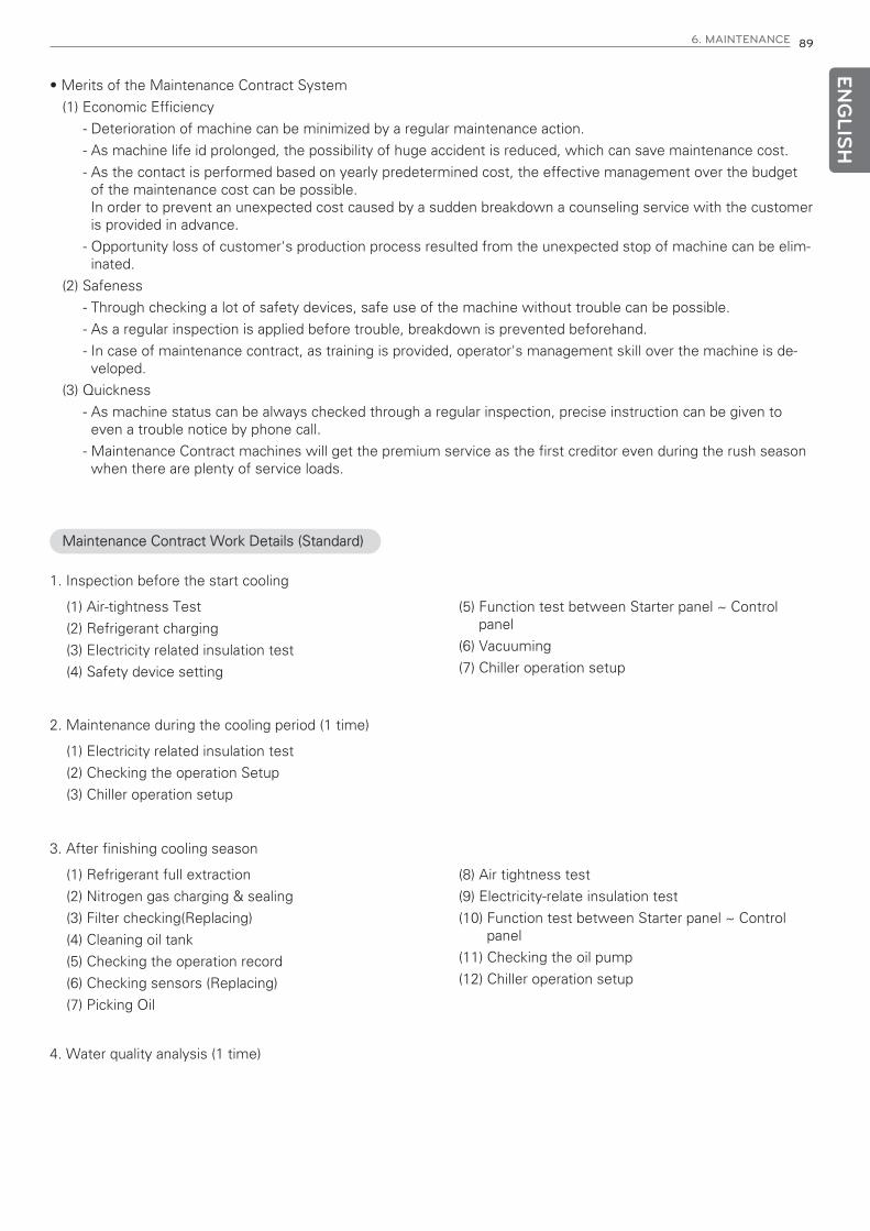
ENG
LISH
6. MAINTENANCE 89
• Merits of the Maintenance Contract System
(1) Economic Efficiency
- Deterioration of machine can be minimized by a regular maintenance action.
- As machine life id prolonged, the possibility of huge accident is reduced, which can save maintenance cost.
- As the contact is performed based on yearly predetermined cost, the effective management over the budgetof the maintenance cost can be possible.In order to prevent an unexpected cost caused by a sudden breakdown a counseling service with the customeris provided in advance.
- Opportunity loss of customer's production process resulted from the unexpected stop of machine can be elim-inated.
(2) Safeness
- Through checking a lot of safety devices, safe use of the machine without trouble can be possible.
- As a regular inspection is applied before trouble, breakdown is prevented beforehand.
- In case of maintenance contract, as training is provided, operator's management skill over the machine is de-veloped.
(3) Quickness
- As machine status can be always checked through a regular inspection, precise instruction can be given toeven a trouble notice by phone call.
- Maintenance Contract machines will get the premium service as the first creditor even during the rush seasonwhen there are plenty of service loads.
Maintenance Contract Work Details (Standard)
1. Inspection before the start cooling
(1) Air-tightness Test
(2) Refrigerant charging
(3) Electricity related insulation test
(4) Safety device setting
(5) Function test between Starter panel ~ Controlpanel
(6) Vacuuming
(7) Chiller operation setup
2. Maintenance during the cooling period (1 time)
(1) Electricity related insulation test
(2) Checking the operation Setup
(3) Chiller operation setup
3. After finishing cooling season
(1) Refrigerant full extraction
(2) Nitrogen gas charging & sealing
(3) Filter checking(Replacing)
(4) Cleaning oil tank
(5) Checking the operation record
(6) Checking sensors (Replacing)
(7) Picking Oil
(8) Air tightness test
(9) Electricity-relate insulation test
(10) Function test between Starter panel ~ Controlpanel
(11) Checking the oil pump
(12) Chiller operation setup
4. Water quality analysis (1 time)
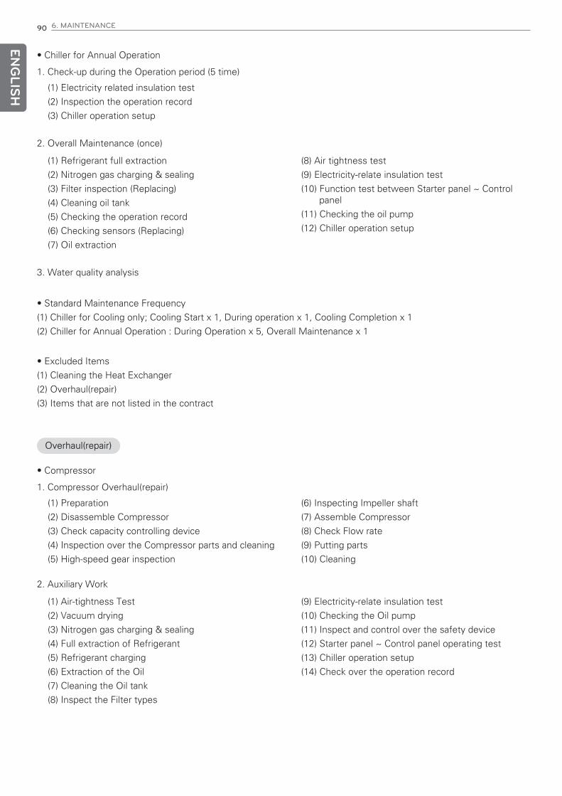
ENG
LISH
90 6. MAINTENANCE
Overhaul(repair)
• Chiller for Annual Operation
1. Check-up during the Operation period (5 time)
• Standard Maintenance Frequency
(1) Chiller for Cooling only; Cooling Start x 1, During operation x 1, Cooling Completion x 1
(2) Chiller for Annual Operation : During Operation x 5, Overall Maintenance x 1
• Excluded Items
(1) Cleaning the Heat Exchanger
(2) Overhaul(repair)
(3) Items that are not listed in the contract
(1) Electricity related insulation test
(2) Inspection the operation record
(3) Chiller operation setup
2. Overall Maintenance (once)
3. Water quality analysis
(1) Refrigerant full extraction
(2) Nitrogen gas charging & sealing
(3) Filter inspection (Replacing)
(4) Cleaning oil tank
(5) Checking the operation record
(6) Checking sensors (Replacing)
(7) Oil extraction
(8) Air tightness test
(9) Electricity-relate insulation test
(10) Function test between Starter panel ~ Controlpanel
(11) Checking the oil pump
(12) Chiller operation setup
• Compressor
1. Compressor Overhaul(repair)
(1) Preparation
(2) Disassemble Compressor
(3) Check capacity controlling device
(4) Inspection over the Compressor parts and cleaning
(5) High-speed gear inspection
(6) Inspecting Impeller shaft
(7) Assemble Compressor
(8) Check Flow rate
(9) Putting parts
(10) Cleaning
2. Auxiliary Work
(1) Air-tightness Test
(2) Vacuum drying
(3) Nitrogen gas charging & sealing
(4) Full extraction of Refrigerant
(5) Refrigerant charging
(6) Extraction of the Oil
(7) Cleaning the Oil tank
(8) Inspect the Filter types
(9) Electricity-relate insulation test
(10) Checking the Oil pump
(11) Inspect and control over the safety device
(12) Starter panel ~ Control panel operating test
(13) Chiller operation setup
(14) Check over the operation record

ENG
LISH
6. MAINTENANCE 91
• Motor
1. Motor overhaul (repair)
(1) Check Stator coil and rotor
(2) Check the Parts
(3) Measure Shaft Vibration, Concentricity degree
(4) Air gap, End Play measurement
(5) Gear disassemble and assemble
(6) Electricity wiring disassemble and assemble
(7) Insulation Resistance Measurement
(8) Winding Resistance measurement
2. Auxiliary works
(1) Refrigerant , Oil pipe Disassemble and Assemble
• Standard Contract Disassemble Inspection(Repairing) Parts
1. Compressor
(1) Bearing
(2) Shaft labyrinth
(3) Impeller shim (1st level, 2nd level)
(4) O-ring, Gasket
(5) Oil filter
2. Motor
(1) Bearing
(2) Rear cover
(3) O-ring, Gasket
(4) Filter Drier, Moisture Indicator
• The Others
1. Compressor
(1) Impeller
(2) Diffuser
(3) Impeller cover
(4) Impeller shaft
(5) Return channel 1, 2, 3
(6) Gear
(7) Plate type Heat exchanger
(8) Capacity adjustment device
(9) Lock nut, bolt
2. Motor
• Excluded Work from standard
1. Starter panel Disassemble Inspection(repairing)
2. Replacing Motor Coil
3. Cleaning the Heat exchanger

ENG
LISH
92 6. MAINTENANCE
6-2. Periodic maintenance
Daily inspection
Checks the evaporator and condenser pressure, oil tank pressure, differential oil pressure and discharge oil pressureof the chiller. Compare the values with the ones of the general chillers maintenance table.
- Compressor and motor daily inspection standard
Classification Inspection items Inspection method Criteria
Compressor,Motor
Motor Cooling ConditionCheck the refrigerant flow via. Mois-ture Indicator
Able to see the refriger-ant flow
Able to see the refrigerant flowMeasure the temperature of theouter surface of the motor using asurface thermometer
Able to see the refriger-ant flow
Motor Drain Temp.Measure the draining pipe's outersurface with the thermometer
Able to see the refriger-ant flow
Motor Drain Oil Flow Measure using Differential PressureAble to see the refriger-ant flow
Compressor discharge gas temp. Check temp. at the control panelAble to see the refriger-ant flow
Vibration/noise Check with the hand and Ear
Measure using the vibration measuring instrument if necessary
Noise: Below 85dB
When there's no abnormal vibration
below x,y,z: 25μm
* The motor adopts liquid refrigerant cooling system. It supplies the liquid refrigerant by the differential pressure be-tween the condensing and evaporation pressure.
* Check and make sure that the refrigerant liquid supplying line's moisture indicator is showing green.If the green color is altered to yellow, it means that the moisture quantity has exceeded more than the standardquantity in the machine. Thus, replace the filter dryer.
Fig 64. Compressor and motor daily inspection standard

ENG
LISH
6. MAINTENANCE 93
- Daily inspection of Condensers
* If the outlet temperature of the cooling water is below 21°C, condensing pressure would be decreased, which willlead to a lack of differential pressure at the motor cooling and the oil cooler and finally become the situation of insuffi-cient of cooling water.
The main cause of worsening the heat exchange can be seen for the scale attached inside cooling pipe and insuffi-cient cooling water amount.
Fig 65. Condenser daily inspection standard
Classification Inspection items Inspection method Criteria
Condenser
Cooling waterInlet Check at the Panel Below 34 °C
Outlet Check at the Panel 21°C or more
Condensing pressure state Check at the Panel 5~10 kg/cm2
Heat exchanging stateTemperature difference betweencondensing temp. and coolingwater outlet temp.
Temperature difference betweencondensing temp. and coolingwater outlet temp.
- Evaporator daily inspection standards
When evaporation pressure is decreased, the evaporator tube freezes and eventually damaged, or compressor surgewould also be possible. Causes of the decreased evaporating pressure would be insufficient refrigerant quantity, lowtemperature water and abnormal heat exchanging efficiency. Like the condenser tubes, if foreign substances are inor the scales adhered, corrosion may occur which will lead to a in efficient heat exchanging. This happens to de-crease the refrigeration ability or may be the cause for surge.
Fig 66. Evaporator daily inspection standard
Classification Inspection items Inspection method Criteria
Evaporator
Chilled waterInlet Check at the Panel Below 5~15°C
Outlet Check at the Panel Above 3°C
Above 3°C Check at the Panel 5~10 kg/cm2
Heat exchanger conditionTemperature Difference betweenthe evaporation temp. and thechilled water outlet temp.
0.5~3°C
Refrigerant charging amount Check through the sight glass
Refrigerant condition Check through the sight glass

ENG
LISH
94 6. MAINTENANCE
- Daily inspection standard of Compressor and motor. Generally, the failure ratio of a machine is distributed as theshape drawn in the following Fig.
Classification Inspection items Inspection method Criteria
Oil
Oil amount Visual inspectionAt least one of two sightglasses should have oil level ap-pearance.
Temp. Check at the Panel 30~60°C
Differential Pressure Check at the Panel 0.8 kg/cm2
Oil Pressure Vibration Check at the Panel No Vibration
LeakageVisual inspection of the oil sys-tem
There shall be no leak
Oil pump Noise Check by ear No abnormality
Oil pump remaining flow opera-tion
Stop the chiller and check withwatch
300 sec.
Figure 67. Compressor and motor machine failure ratio
<Lubrication cycle>
The oil is taken through the manual valve into the tank. The level of the oil can be detected by the one sight glasseson the oil tank. When the compressor is stopped oil should be able to be found through the sight glass.
The temperature of the oil tank is displayed on the panel and while operation, the temperature would be 30~65 °C.
The oil pump transfers the oil from the tank and the pressure at that time would be above 0.8kg/cm2.
The oil pump is sending the oil to the oil filter, where a valve is installed so that there is no need to drain the wholesystem when replacing the filter.
Afterwards the oil is sent to the oil cooler and then cooled by the refrigerant from the condenser.
The refrigerant cools off the oil as low as 30~60°C.
Oil that left the cooler passes through the oil pressure transducer and then to the refrigerant expanding valve’s tem-perature sensor box, flows to the bearings and gears for lubrication.
The oil temperature is measured at the high-speed thrust bearing and the oil is drained to the oil tank that is locatedat the lower part of the compressor.
The control device operates the oil to the oil pump prior to the main operation for 120~180 seconds at a constantpressure. At stoppage when the main operation has stopped, it performs a 300 seconds of after lubrication.
Soft start-up opens guide vane slowly during the start-up to prevent foaming of the oil.
If the guide vane opens too quickly, it will let the refrigerant in the oil to be boiled because of the intake pressure'srapid decrease, which will eventually cause foaming. This foaming will lead to dropping the pressure in oil pump, andthe low pressure of oil lead finally bad lubrication.

ENG
LISH
6. MAINTENANCE 95
Monthly inspection
- Compressor and motor monthly inspection standard
- Lubrication system monthly inspection standard
Classification Inspection category Inspection method Criteria
Compressorand Motor
Motor insulation Measure at 1000V mega Above 100 MΩ
Vane operation
Visual inspection of the openingstatus
In Vane Full Close, 0%
Check indication in Vane Full Open, 100%
Check the status of opening indi-cation
Soft movement of Indication Value
Protector insulation500V mega(Protector ~ Main Coil, Protector~ ground) Measuring
Above 3 MΩ
Characteristics ofstart-up
Mark ● for the correspondingstart-up method
1. Direct standing start-up
2. Y-Δ start-up
3. Kondorfer start-up
4. Reactor start-up
* In case of chilled water outlettemp _°C
Time of start-up current flow t: 5~25 sec.
Start-up current: A
Timer set value (sec.)
Fig 68. Compressor and motor monthly inspection standard
Fig 69. Lubrication system monthly inspection standard
• Generally the starting current of the motor is about 600% that of the rated current in direct input. And in case of y-Δ , it is 200%, for kondorfer 250%, and for Reactor 400%.
• Measuring frequency and record should be at least once a month for daily/monthly inspections. This data can bethe clue of solution if problems are occurred to the motor.
Classification Inspection items Inspection method Criteria
OilOil charging amount Check through the sight glass
Refer to the standard chargingamount
Oil pump motor insulation Check through the sight glass 3MΩ

ENG
LISH
96 6. MAINTENANCE
Yearly inspection
- Yearly inspection
Classification Inspection items Inspection method Criteria
MotorMotor Terminal fas-ten bolt
Check the slacknessCheck the loose
Loose terminal finishing state
CondenserChemical analysis Water quality analysis Water quality standard
Tubes conditionCheck it at the operation record orby opening the waterbox.
No pollution
EvaporatorChemical analysis Water quality analysis Water quality standard
Tubes conditionCheck it at the operation record orby opening the waterbox.
No pollution
Oil and lubricant
Oil cooler cleaning Clean by refrigerantNo corrosion or pollution should be pres-ent
Ejector cleaning Disassemble cleaning No abnormality
Filter cleaningFilter exchanging, Cleaning thehousing
No abnormality
Oil tank cleaning Disassemble cleaning No pollution
Oil Replacing 2000 hours or 1 year
Fig 70. Yearly inspection standard
<Water quality analysis>
The cooling water at the open circulation type cooling tower uses the evaporation latent heat to lower down thewater temperature and also recycles it.
At this time the water evaporates and the chloride ions in the water and the acid ions will increase. This will lead toenrichment situation and eventually deteriorate the water quality.
Also, in the cooling tower, water and air are always in contact with each other and the contaminating material(auto-mobile exhaust gas, sulfurous acid gas, dust, gas of chemical plants such as ammonia or petroleum gas, etc.) deterio-rates the water quality even more.
These pollutant causes can corrode the pipe, scales adhered causes the tubes to have holes and lockouts which areleading to a decreasing effect of heat exchanger.
Therefore, it may end to replacing the tubes, increased power cost, or the chiller failure.
Thus, cooling water quality must be maintained at a certain level.
Water quality analysis should be taken place periodically and if the results are out of the standards boundary(Table23.), it must be replaced. At the beginning of the season and at the initial starting of the machine, water quality analy-sis is inevitable.
To prevent the cooling water enrichment, certain amount of cooling water should be drained during the circulationand then supplying fresh cooling water. Another way of water quality analysis would be using chemical handling.
<Tubes State>
If water corroded dirt is adhered or foreign substances are mixed in the tubes, resistance is increased which makes ithard for the chiller to have a good efficiency. It also makes it easy to cause surge.
If sandy like solid materials are mixed in the cooling water, erosion or corrosion may occur at the entrance of thetubes, therefore when cleaning the tubes make sure that you check the inner surface of it.
Install a filter at the inlet of the cooling water pipe. Generally, a cooling tower is used for the cooling water system,but when using the subterranean water or the riparian water it is possible for the scales to be adhered easily due tolow quality of water compared to the chilled water.

ENG
LISH
6. MAINTENANCE 97
# Refrigerant and oil charge amountSingle stage centrifugal chiller
Table 24. Refrigerant and oil charging amount for Single Stage centrifugal chiller
Note)
(1) Name and unit of the items are based on KS MD100.
(2) O sign within the table refers to the factor related to the corrosion or scaling trend.
(3) Unit and value within the parenthesis show data based on the previous unit, for reference.
(4) If the temperature is high (40°C or above), generally the corrosion rate becomes high especially for steel that di-rectly contacts water without any protective coating. It is recommended to have an effective plan for the watersuch as adding anti-corrosive additive or air removal process, etc.
Item
Cooling water systemChilled water system Trend
Circulation type Oncethrough type
Circulatingwater
Suppliedwater
Oncethroughwater
Circulatingwater
(Below 20°C)
Suppliedwater
Corrosion Scaling
Sta
ndar
d ite
m
below 80below 800
below 30below 300
below 40below 400
below 40below 400
below 30below 300
Ref
eren
ce it
em Not detected
Not detected
Not detected
Not detected
Not detected
pH(25°C)
Electric conductivity (Ma/m)(25°C) (㎲/cm) (25°C)
Chloride ion (mgCl ̄/L)
Sulfuric ion (mgSO4 2 ̄/L)
Acid consumption (pH4.8)(mgCaCO3/L)
Total hardness (mgCaCO3/L)
Calcium hardness (mgCaCO3/L)
Ion silica (mgSiO2/L)
Iron (mgFe/L)
Copper (mgCu/L)
Sulfide ion (mgSO2 ̄/L)
Ammonium ion (mgNH4+/L)
Residual chlorine (mgCl/L)
Free carbon dioxide (mgCO2/L)
Stability index
6.5~8.2 6.0~8.0 6.8~8.0 6.8~8.0 6.8~8.0 ㅇ ㅇ
ㅇ ㅇ
below 200 below 50 below 50 below 50 below 50 ㅇ
below 200 below 50 below 50 below 50 below 50 ㅇ
below 100 below 50 below 50 below 50 below 50 ㅇ
below 200 below 70 below 70 below 70 below 70 ㅇ
below 150 below 50 below 50 below 50 below 50 ㅇ
below 50 below 30 below 30 below 30 below 30 ㅇ
below 1.0 below 0.3 below 1.0 below 1.0 below 0.3 ㅇ
below 0.3 below 0.1 below 1.0 below 1.0 below 0.1 ㅇ ㅇ
ㅇ
below 1.0 below 0.1 below 1.0 below 1.0 below 0.1 ㅇ
below 0.3 below 0.3 below 0.3 below 0.3 below 0.3 ㅇ
below 4.0 below 4.0 below 4.0 below 4.0 below 4.0 ㅇ
5.0~7.0 ㅡ ㅡ ㅡ ㅡ ㅇ ㅇ
Table 23. Water quality management standard for chilled water/cooling water
FrameRefrigeration capacity
(RT)Amount of refrigerant
(kg)Oil quantity
(L)
3 250 ~ 400 450 40
4 500 ~ 600 550 40
5 650 ~ 850 750 60
6 900 ~ 1300 950 62
7 1400 ~ 2000 2100 120

ENG
LISH
98 6. MAINTENANCE
6-3. Maintenance during off-season
(1) If the operation needs to be stopped, to reduce the machine pressure and leak possibility, move the refrigerant toa separate refrigerant container.
(2) To prevent intake of air into the machine, store the machine with about 5kg refrigerant charged or to apply 0.5kgnitrogen.
(3) If the place where the machine is installed goes below 0°C frequently, to prevent the freezing, drain the coolingwater, chilled water and condensed water. Also open the waterbox drain.
(4) Leave the oil charged in the machine, and to maintain the minimum oil tank temperature, supply power to the oilheater.

ENG
LISH
6. MAINTENANCE 99
6-4. Annual maintenance(1/2)
Inspection items
Motor coolingstatus
Check refrigerant flow status from moisture indicator
Check flow status Yes No
Pass Fail
Pass Fail
Pass Fail
Pass Fail
100MΩ or more
10~30 °C
MΩ
A=A
Start-up current: A
Timer set value (sec.)
T1: start-uptimerT2: subsi-diarytimer
Check timer set value with independent timeroperation test after disconnecting high voltage.
Check 0, 100%
Shall operate smoothly
In normal operation
Less than 105% of the rated
10~60 sec.
About 30~90°C
When there is noproblem
Timer
High
pre
ssur
eLo
w pr
essu
re
Kondorfer reactor Actualmeasurement
Start-up timeT=5~25 sec. t =
sec.
sec.
°C
A
Touch the surface of the motorwith hand
Measured at 1000V
Check opening 0~100%
Check opening status
Check opening ratio
Check current value
After chiller is stopped, check fromhalf-load side of the motor whenthe meter axes stopped time
Measure the surface of the boltswith thermometer
Touch with hand or checkwith ears
Motorinsulation
Start-upcharacteristics(mark O in thecorrespondingstart-upmethod)
Vaneoperation
Vane opening
Operation current
Motor stopped time
Vibration noise
Dischargegas temp.
Com
pressor
Inspection method Criteria DecisionActualmeasurement
Kondorfer, reactor
In case of chilled wateroutlet temp. ( ) °C
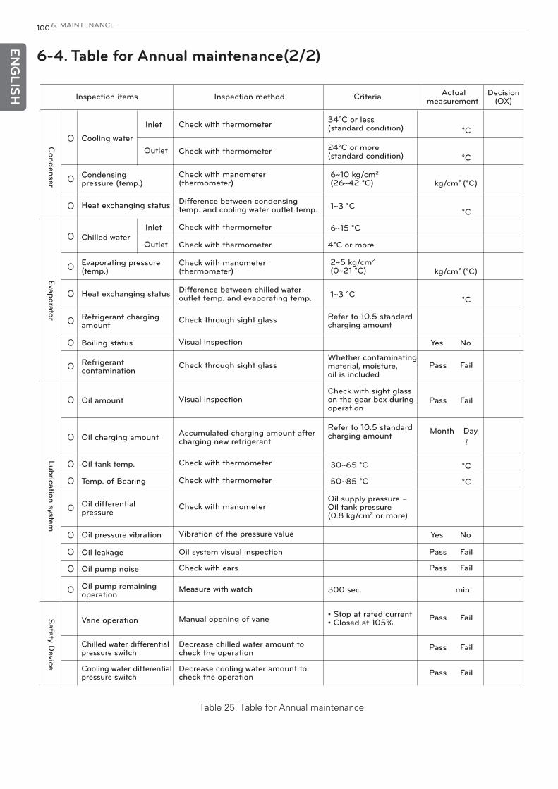
ENG
LISH
100 6. MAINTENANCE
6-4. Table for Annual maintenance(2/2)
Inspection items
Cooling water
Condensingpressure (temp.)
Heat exchanging status
Chilled water
Evaporating pressure(temp.)
Heat exchanging status
Refrigerant chargingamount
Boiling status
Refrigerantcontamination
Oil amount
Oil charging amount
Oil tank temp.
Temp. of Bearing
Oil differentialpressure
Oil pressure vibration
Oil leakage
Oil pump noise
Oil pump remainingoperation
Vane operation
Chilled water differentialpressure switch
Cooling water differentialpressure switch
Decrease cooling water amount tocheck the operation
Decrease chilled water amount tocheck the operation
Manual opening of vane
Measure with watch
Check with ears
Oil system visual inspection
Vibration of the pressure value
Check with manometer
Check with thermometer
Check with thermometer
Accumulated charging amount aftercharging new refrigerant
Visual inspection
Visual inspection
Check through sight glass
Difference between chilled wateroutlet temp. and evaporating temp.
Check with manometer(thermometer)
Check with thermometer
Check with thermometer
Difference between condensingtemp. and cooling water outlet temp.
Check with manometer(thermometer)
Check with thermometer
Check with thermometer 34°C or less (standard condition)
24°C or more(standard condition)
6~10 kg/cm2
(26~42 °C)
2~5 kg/cm2
(0~21 °C) kg/cm2 (°C)
kg/cm2 (°C)
°C
°C
°C
°C
Yes No
Yes No
Pass Fail
Pass Fail
Pass Fail
Pass Fail
Pass Fail
Pass Fail
Pass Fail
°C
°C
1~3 °C
1~3 °C
30~65 °C
50~85 °C
6~15 °C
4°C or more
Refer to 10.5 standardcharging amount
Whether contaminatingmaterial, moisture,oil is included
Check with sight glasson the gear box duringoperation
Refer to 10.5 standardcharging amount Month Day
Oil supply pressure – Oil tank pressure (0.8 kg/cm2 or more)
300 sec. min.
• Stop at rated current• Closed at 105%
Check through sight glass
Inlet
Outlet
Inlet
Outlet
Condenser
EvaporatorLubrication system
Safety D
evice
Inspection method Criteria Decision(OX)
Actualmeasurement
Table 25. Table for Annual maintenance
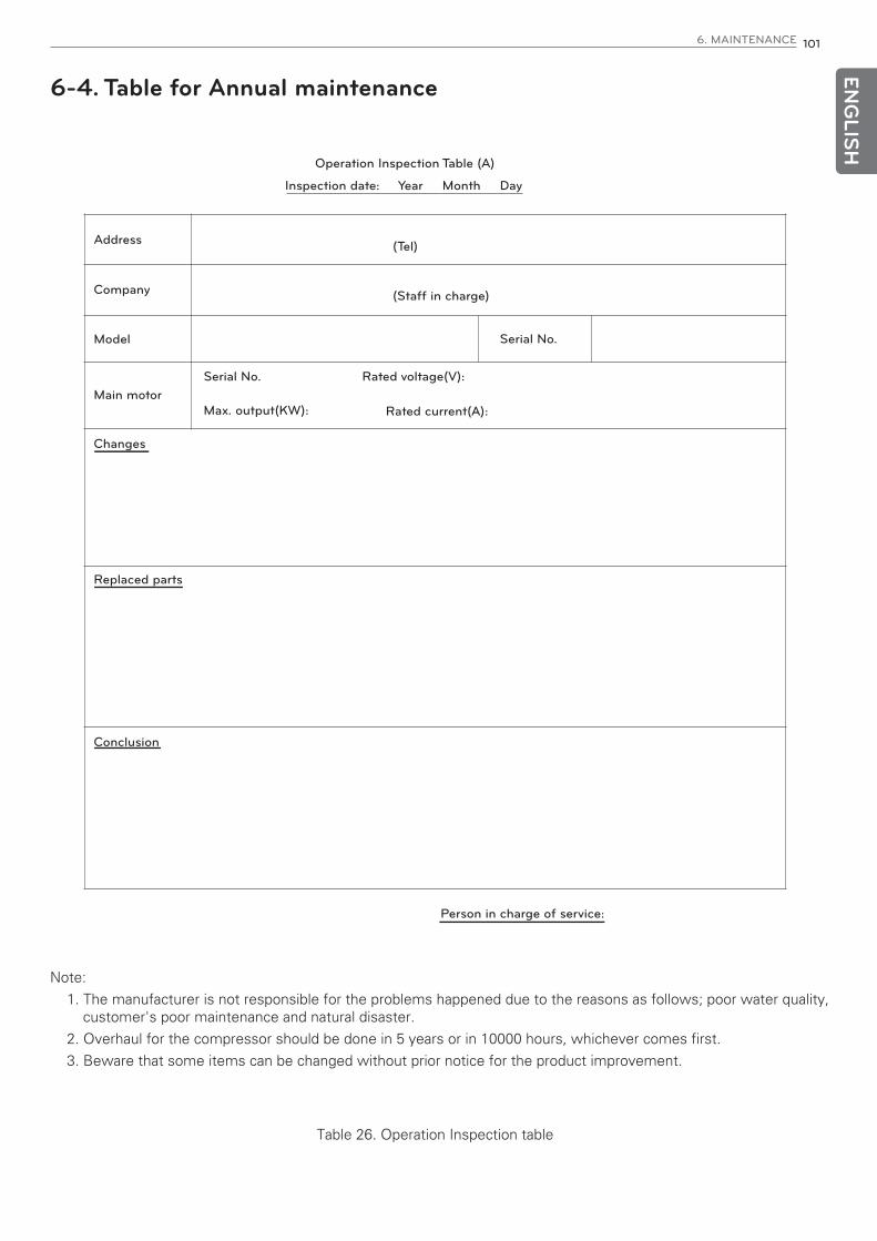
ENG
LISH
6. MAINTENANCE 101
6-4. Table for Annual maintenance
Operation Inspection Table (A)
Address (Tel)
(Staff in charge)
Serial No.
Company
Model
Main motor
Changes
Replaced parts
Conclusion
Person in charge of service:
Serial No. Rated voltage(V):
Max. output(KW): Rated current(A):
Inspection date: Year Month Day
Note:
1. The manufacturer is not responsible for the problems happened due to the reasons as follows; poor water quality,customer's poor maintenance and natural disaster.
2. Overhaul for the compressor should be done in 5 years or in 10000 hours, whichever comes first.
3. Beware that some items can be changed without prior notice for the product improvement.
Table 26. Operation Inspection table

ENG
LISH
102 6. MAINTENANCE
6-5. Oil maintenance
Compressor oil replacement
- Checking the Lubrication System
Record the level of the oil on the oil tank sight glass in operation, and check the level when the chiller is stopped. If thelevel has dropped below the lower part sight glass, it is necessary to check whether the oil recovery system is workingproperly. If oil is needed, add it through the oil charging valve. To charge the oil opposite from the refrigerant pressure, apump is needed. The charging quantity of the oil should be referred to LG Electronics and the specification of the addi-tional oil should match with that of LG Electronic’s chiller oil. Added oil shall be recorded for its amount and date.
- Oil specification
Use oil recommended by LG.
Category UnitCharacteris-
tic valueMeaning
Density kg/m3 960 Check for the specified product and for any foreign substance mixed
Color °C °C L0.5 Check initially specified product
Ignition point mm3/s 250 Fire and explosion risk, preservation stability
Flowing point mgKOH/g - 40 Stability during the initial start-up, preservation stability
Kinematic viscosity @ 40 °C 67.3 Lubrication, friction loss, sealing effect, cooling capability
@ 100 °C 8.29
Viscosity index 90 Relationship to the viscosity change due to temp. change
Total acid value 0.01Measure oxidation of the oil itself compared to the initial total
acid value
Corrosion of the copper plate
1 Anti-corrosion ability of the oil
(100 °C, 3h)
<Available oils>
- Oil from LG- Japan sun oil : Icecold SW68
- Castrol : Castrol Icematic SW68
• Oil replacement
We recommend you to replace the oil on the first year of the chiller's operation and every 3-year period dependingon the oil analysis.
1) Mark the current oil level.
2) Open the control circuit breaker and oil heater circuit breaker.
3) Gradually open the oil charging valve to drain the oil. Opposite from the chiller pressure, open the valve veryslowly.
4) After locking the valves at both ends of the oil filter, use the valve to gradually reduce the pressure within the oilfilter, and change the oil filter.
5) Charge oil to the machine using a pump.To be charged till the level of middle or higher at the sight glass, approximately 50~60ℓ of oil is needed. Heatuntil the oil temperature reaches 40°C by turning on the oil heater. For the sake of controlling test, operate the oilpump manually for 2 minutes. The level of the oil should be indicating at the sight glass.
Table 27. Oil specification

ENG
LISH
6. MAINTENANCE` 103
Oil Filter Change
- Oil Filter Change
Replace the oil filter annually or in the time of overhaul.
Oil filter can be replaced in a condition that the refrigerant is in the chiller.
1) Check if the compressor is in the stop state and also if the compressor circuit breaker is opened.
2) Shut down the oil pump power.
3) Close the oil filter separator valves.
4) When opening the oil filter housing, do it slowly.
5) Make vacuum in the filter housing after the filter exchange or assembling. After the vacuum has been done, openthe separation valve and if there is insufficient amount of oil, add oil through the charging valve.
! CAUTION
Decrease the pressure of the oil filter housing very slowly because it is in a high temperature state.

ENG
LISH
104 6. MAINTENANCE
6-6. General Maintenance
! CAUTION
The refrigerant HFC-134a dissolves oil and some non-metallic material, dries skin, and makes oxygen deficiency resulting in suffoca-tion at high concentration. Thus be very careful not to inhale or touch by hand or eye contact when you handle the refrigerant.
Non-periodical maintenance
• Maintenance of the compressor bearing and the gearThe core of maintaining bearing and the gear can be said adequate lubrication. Preserve the recommended oilamount, temperature and pressure by using the right level of oil. Do a thorough maintenance check-up on the lubri-cation system periodically. To inspect the bearing, the compressor must be completely disassembled.To take out the bearing and to inspect it, a high technology specialist is needed. Excessive abrasion can occasion-ally be detected by excessive vibration or by the bearing's temperature.
• Refrigerant leak inspection
HFC-134a has higher pressure than air in room temperature, so it requires the refrigerant leak test utilizing elec-tronic detector, halogen leak detector or soapy water.
If the refrigerant leak is overall the entire chiller with large volume, immediately stop using the system and fix itfirst. If the refrigerant was lost or the machine has been opened during the service period, the chiller itself or re-lated tank must be taken leak test by adding pressure.
Refer to 5-5-2 for leak inspection.
Charging refrigerant and leakage test
- Refrigerant characteristics
Usage refrigerant is HFC-134a. HFC-134a evaporates at -26°C in normal air pressure, so it shall be stored in a pressured container or storage tank.Refrigerant has almost no smell when it is mixed with air, and it is non-combustible in air pressure.
<Characteristics Table>
Molecule formula CH2F-CF3
Molecule amount 102.031
Boiling point (air pressure) °C - 26
Freezing point °C - 101
Critical temp. °C 101
Critical pressure kg/cm2.A 41.5
Density of saturated fluid (25°C) kg/m3 1206
Specific volume of saturated vapor (25°C) m3/kg 0.031
Specific heat ratio, vapor (25 °C, air pressure) 1.1186
Evaporative latent heat (25°C) kcal/kg 42.54
Table 28. The property of HFC-134a

ENG
LISH
6. MAINTENANCE 105
- The adjustment of refrigerant charging amount
If it is necessary to control the refrigerant charging amount for a better performance of the machine itself, operatethe machine in a design load and add or remove the refrigerant until it satisfies the difference temperature of thechilled water outlet and the evaporator refrigerant.Do not over charge. Refrigerant can be charged through the storage tank or directly charged into the chiller.
- Refrigerant leak inspection
HFC-134a has higher pressure than air in room temperature, so it requires the refrigerant leak test utilizing elec-tronic detector, halogen leak detector or soapy water. Check for a good room ventilation and check whether theleaked refrigerant is concentrated in one place of the room to prevent a wrong measurement result.Before performing any repair for leak, move all refrigerant from the leaked container.
- Refrigerant leakage
If there is large refrigerant leak, chiller performance degraded or operation impossible, it is recommended to stopthe chiller and repair first.
- Refrigerant filter
Refrigerant filter /drier in the refrigerant cooling pipes of the motor needs to be replaced once a year. It may requiremore frequent replacement according to the status of the filter. To find the existence of moisture in the refrigerant,sight glass is installed next to the filter. If moisture through the sight glass is detected, perform a thorough leak in-spection to find the source of the water.
Cleaning Heat exchanger tubes (Evaporator/Condenser)
Inspect Heat exchanger tubes
- Evaporator
When the first operation season is over, clean the evaporator tubes.
These tubes have foreign substances inside. Thus to clean the tubes thoroughly, a special caution should be exer-cised. The tubes condition, at this time, will become the data to determine how often tubes needs to be cleanedand whether the water treatment in the chilled water(brine) system is appropriate. Check for any corrosion or scalein the chilled water inlet/outlet temperature sensor. For corrosion, replace the sensor, and for scale, remove thescale.
- Condenser
Cooling water circuit is generally an open type system, so it is easy to have the tubes contaminated and scale to beadhered. Therefore, the tubes in condenser need to be cleaned at least once a year. If the water quality is contami-nated, clean more frequently. Check the corrosion or scale in the cooling water inlet/outlet temperature sensor. Forcorrosion, replace the sensor, and For scale, remove the scale.
The reason that it is higher than the normal condenser pressure and not reaching previous chilling load is generallybecause tubes are contaminated or there is an air in the machine.
If the temperature difference between cooling water outlet and condenser refrigerant is great, the condenser tubesmay be contaminated or water flow is not good.
HFC-134a is a high pressure refrigerant, so it is easier to have refrigerant leak than air enters inside.
During the cleaning of the tube, use a specially designed brush to prevent scratch on the tubes wall.
Never use wire brush.
! CAUTION
For the prevention of severe scales and the removal of the scales, treat with chemical. For a proper treatment, consult withwater treatment specialist.

ENG
LISH
106 6. MAINTENANCE
Check items before operation after long term stop
- Check list before start-up
1. Control Panel and Electric linesShut down the breaker, check for any foreign substance in the control parts, switches, etc.. Controls theswitches to check whether it operates in normal and connection status for each connector are OK.
2. VoltageRead the voltage meter on the starter panel and check if it matches with the usage voltage on the name plate ofthe chiller.
3. Chilled and cooling water circulation systemOperate cooling water and chilled water pumps to check if their operation status are properly displayed on thepanel.
- Control device operation test
1. Check the connection conditionCheck if the power, sensor, etc. are properly connected.Special checking should be taken to power line.
2. After power on, check the display status of the panel.Pay special attention if there is any sign of short circuit for about 5 sec. after power on.If any of the following symptoms occur, immediately disconnect power and check for problem.
3. Check values displayed on the panelCheck whether each sensor value displayed on the panel is correct.If any error message is displayed or sensor value is not normal, check sensor connection status.
4. No power operationRun while the main motor power is off, and check for normal operation to the operation signal of starter panel.If any error message appears, check the corresponding part.
- Check safety devices
Flow operation test for chilled water and cooling waterClose the valves installed on the cooling water and chilled water pipes to check whether the flow checking switch isworking correctly.

ENG
LISH
7. TROUBLESHOOTING 107
Actions for problems
• How to react to the problem display from controller
• Please take actions according to the following instructions
Check the displayed contents and refer to the help message. Select help menu corresponding to the problemmessage and check the contents of the problem and how to react. Remove the cause of the problem accordingto the parts or drawing of the circuit related to the problem or manual. If the contents for the problem is no in themanual or drawing, consult our experts. Check the temperature control status, pressure status, etc.
Troubleshooting (1/3)
Abnormal category Displayed contents Cause Action
Chilled Water Inlettemperature Sensor
Chilled Water Inlet tem-perature Sensor Error
Sensor disconnected/short-circuit Main board malfunctionCheck parts status or wiringReplace parts or re-wire`
Chilled water outlettemperature sensor
Chilled water outlet tem-perature sensor Error
Sensor disconnected/short-circuit Main board malfunctionCheck parts status or wiringReplace parts or re-wire`
Cooling water inlettemperature Sensor
Chilled water outlet tem-perature sensor Error
Sensor disconnected/short-circuit Main board malfunctionCheck parts status or wiringReplace parts or re-wire`
Cooling water outlettemperature Sensor
Chilled water outlet tem-perature sensor Error
Sensor disconnected/short-circuit Main board malfunctionCheck parts status or wiringReplace parts or re-wire`
Compressor dischargetemperature sensor
Compressor dischargetemperature sensor error
Sensor disconnected/short-circuit Main board malfunctionCheck parts status or wiringReplace parts or re-wire`
Bearing temperaturesensor
Bearing temperature sen-sor problem
Sensor disconnected/short-circuit Main board malfunctionCheck parts status or wiringReplace parts or re-wire`
Motor winding R phasetemperature sensor
Motor winding R phasetemperature sensor error
Sensor disconnected/short-circuit Main board malfunctionCheck parts status or wiringReplace parts or re-wire`
Motor winding S phasesensor
Motor winding S phasesensor error
Sensor disconnected/short-circuit Main board malfunctionCheck parts status or wiringReplace parts or re-wire`
Motor winding T phasesensor
Motor winding T phasesensor error
Sensor disconnected/short-circuit Main board malfunctionCheck parts status or wiringReplace parts or re-wire`
Evaporator pressuresensor
Evaporator pressure sen-sor error
Sensor disconnected/short-circuit Main board malfunctionCheck parts status or wiringReplace parts or re-wire`
Condenser pressuresensor
Condenser pressure sen-sor error
Sensor disconnected/short-circuit Main board malfunctionCheck parts status or wiringReplace parts or re-wire`
Oil tank pressure tem-perature sensor
Oil tank pressure temper-ature sensor error
Sensor disconnected/short-circuit Main board malfunctionCheck parts status or wiringReplace parts or re-wire`
Oil pump pressuresensor
Oil pump pressure sensorerror
Sensor disconnected/short-circuit Main board malfunctionCheck parts status or wiringReplace parts or re-wire`
Current transducer Current sensor error Sensor disconnected/short-circuit Main board malfunctionCheck parts status or wiringReplace parts or re-wire`
Voltage transducer Voltage sensor error Sensor disconnected/short-circuit Main board malfunctionCheck parts status or wiringReplace parts or re-wire`
7-1. Causes and actions for alarms
7. TROUBLESHOOTING
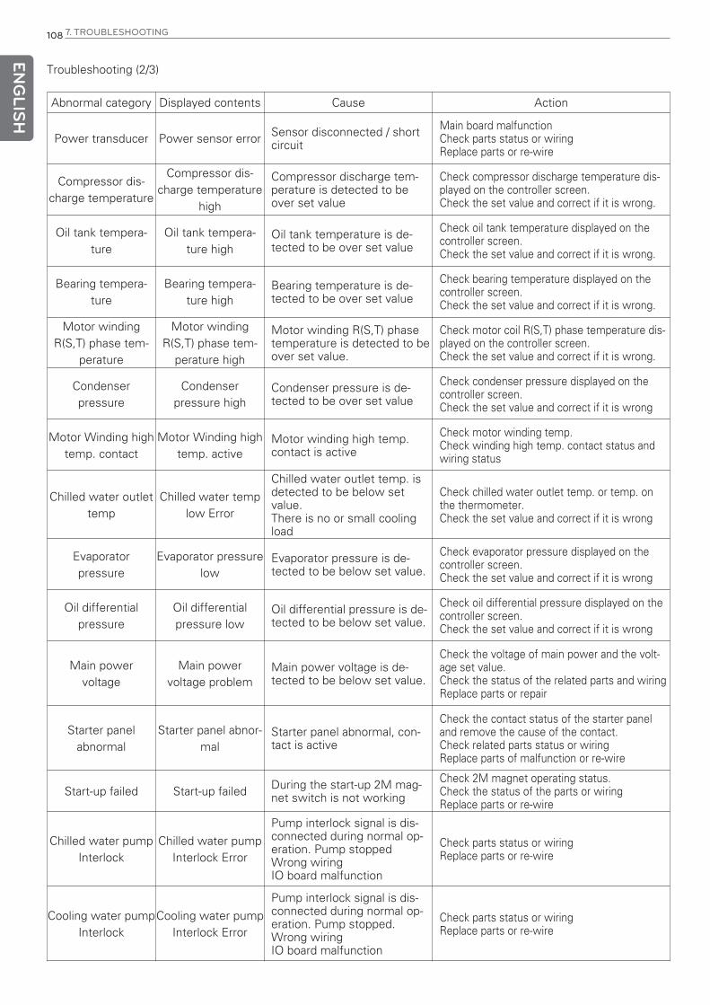
ENG
LISH
108 7. TROUBLESHOOTING
Troubleshooting (2/3)
Abnormal category Displayed contents Cause Action
Power transducer Power sensor error Sensor disconnected / shortcircuit
Main board malfunctionCheck parts status or wiringReplace parts or re-wire
Compressor dis-charge temperature
Compressor dis-charge temperature
high
Compressor discharge tem-perature is detected to beover set value
Check compressor discharge temperature dis-played on the controller screen.Check the set value and correct if it is wrong.
Oil tank tempera-ture
Oil tank tempera-ture high
Oil tank temperature is de-tected to be over set value
Check oil tank temperature displayed on thecontroller screen.Check the set value and correct if it is wrong.
Bearing tempera-ture
Bearing tempera-ture high
Bearing temperature is de-tected to be over set value
Check bearing temperature displayed on thecontroller screen.Check the set value and correct if it is wrong.
Motor windingR(S,T) phase tem-
perature
Motor windingR(S,T) phase tem-
perature high
Motor winding R(S,T) phasetemperature is detected to beover set value.
Check motor coil R(S,T) phase temperature dis-played on the controller screen.Check the set value and correct if it is wrong.
Condenserpressure
Condenserpressure high
Condenser pressure is de-tected to be over set value
Check condenser pressure displayed on thecontroller screen.Check the set value and correct if it is wrong
Motor Winding hightemp. contact
Motor Winding hightemp. active
Motor winding high temp.contact is active
Check motor winding temp. Check winding high temp. contact status andwiring status
Chilled water outlettemp
Chilled water templow Error
Chilled water outlet temp. isdetected to be below setvalue.There is no or small coolingload
Check chilled water outlet temp. or temp. onthe thermometer.Check the set value and correct if it is wrong
Evaporatorpressure
Evaporator pressurelow
Evaporator pressure is de-tected to be below set value.
Check evaporator pressure displayed on thecontroller screen.Check the set value and correct if it is wrong
Oil differentialpressure
Oil differentialpressure low
Oil differential pressure is de-tected to be below set value.
Check oil differential pressure displayed on thecontroller screen.Check the set value and correct if it is wrong
Main power voltage
Main power voltage problem
Main power voltage is de-tected to be below set value.
Check the voltage of main power and the volt-age set value.Check the status of the related parts and wiring Replace parts or repair
Starter panelabnormal
Starter panel abnor-mal
Starter panel abnormal, con-tact is active
Check the contact status of the starter paneland remove the cause of the contact.Check related parts status or wiringReplace parts of malfunction or re-wire
Start-up failed Start-up failed During the start-up 2M mag-net switch is not working
Check 2M magnet operating status.Check the status of the parts or wiring Replace parts or re-wire
Chilled water pumpInterlock
Chilled water pumpInterlock Error
Pump interlock signal is dis-connected during normal op-eration. Pump stoppedWrong wiringIO board malfunction
Check parts status or wiringReplace parts or re-wire
Cooling water pumpInterlock
Cooling water pumpInterlock Error
Pump interlock signal is dis-connected during normal op-eration. Pump stopped.Wrong wiringIO board malfunction
Check parts status or wiringReplace parts or re-wire

ENG
LISH
7. TROUBLESHOOTING 109
Troubleshooting (3/3)
Abnormal category Displayed contents Cause Action
Vane closed switch Vane is not closed Start Vane CloseSwitch is open
Check vane closed switch operation status andwiring.Adjust position of vane closed switch or re-wire
Condenser highpressure
Condenser highpressure contact
active
Condenser pressure is higherthan the pressure switch setstatus
Check condenser pressure.Check condenser high pressure contact statusor wiringReplace parts or re-wire
Evaporator refriger-ant low temp.
Evaporator Refriger-ant Low Temp Con-
tact Activate
Evaporator refrigerant temp.is lower than the switch setstatus
Check evaporator refrigerant temp.Check evaporator refrigerant low temp. contactstatus or wiringReplace parts or re-wire
Surge occurred Surge occurred Surge occurred Check surge current change amountReset the surge protection area
Oil pumpOil pump overload
contact activeOil pump current is more thanoverload set current
Check oil pump overload setting status andwiringReplace parts or re-wire
Chilled water flowinterlock
Chilled water flowlow abnormal
Flow signal is disconnectedduring normal operation.Pump stoppedFlow (differential pressure)switch setting problem.Wrong wiring.IO board malfunction
Correct set value and checkCheck parts status or wiring.Replace parts or re-wire
Cooling water flowinterlock
Cooling water flowlow abnormal
Pump interlock signal is dis-connected during normal op-eration.Pump stoppedWrong wiring.IO board malfunction
Check parts status or wiring.Replace parts or re-wire
Start-up competedsignal (2M)
Delta contactoropen during opera-
tion
Delta contactor signal is dis-connected during operation
Check parts status or wiring.Replace parts or re-wire
Evaporator refriger-ant temp.
Evaporator refriger-ant temp. low temp.
problem
Evaporator refrigerant temp.is detected to be lower thanset value
Check evaporator refrigerant temp. displayed onthe controller screen.Check the set value and correct if it is wrong.
CommunicationMAIN <-> I/O com-
munication errorCommunication error be-tween boards
Check parts status or wiring.Replace parts or re-wire
Sensor correctionSet value is dam-
aged. Sensor needsto be set
Sensor is not corrected Calibration using precision resistance device
Main board Main board reset Main board is reset during op-eration
Check voltage applied to the controller andwiring.Remove cause of noise.
Display device Display board reset Display board is reset duringoperation
Check voltage applied to the controllerRemove cause of noise.Check wiring
Table 29. Troubleshooting
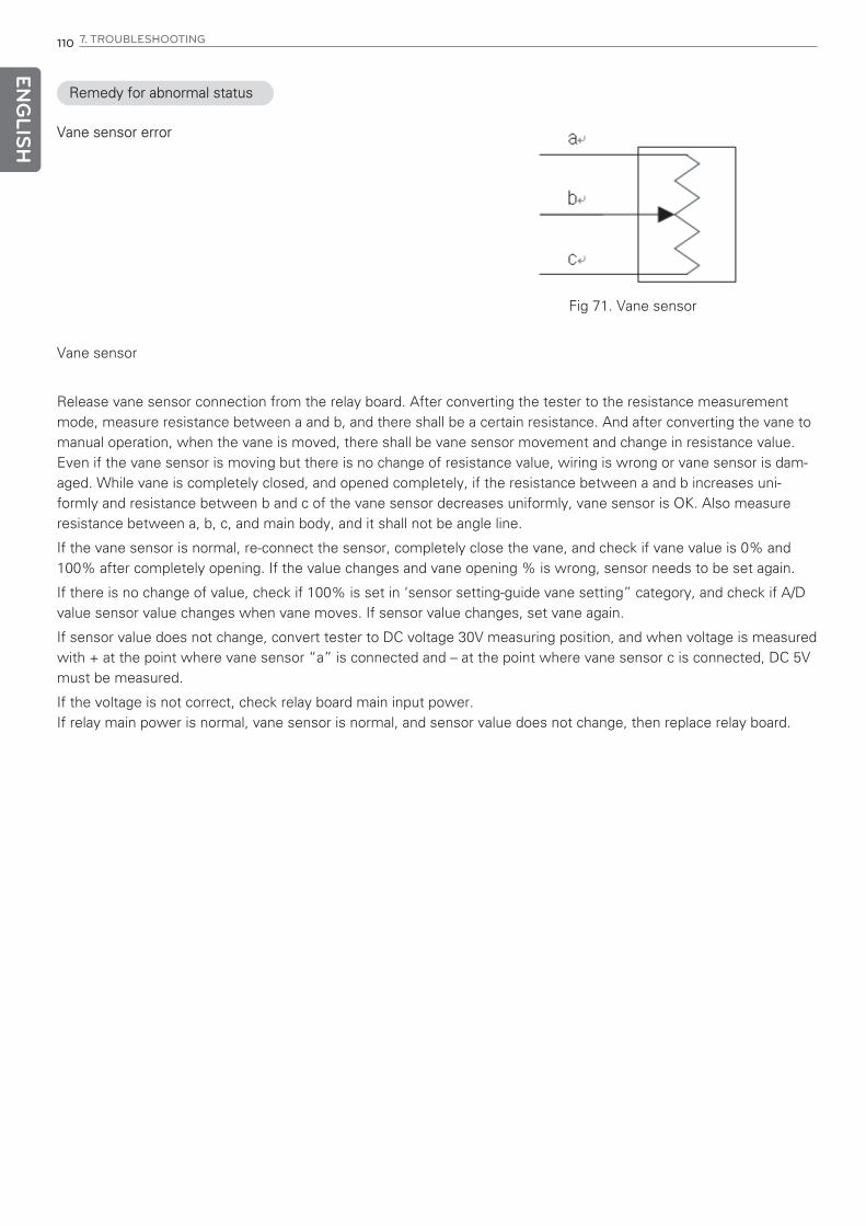
ENG
LISH
110 7. TROUBLESHOOTING
Remedy for abnormal status
Vane sensor error
Fig 71. Vane sensor
Vane sensor
Release vane sensor connection from the relay board. After converting the tester to the resistance measurementmode, measure resistance between a and b, and there shall be a certain resistance. And after converting the vane tomanual operation, when the vane is moved, there shall be vane sensor movement and change in resistance value.Even if the vane sensor is moving but there is no change of resistance value, wiring is wrong or vane sensor is dam-aged. While vane is completely closed, and opened completely, if the resistance between a and b increases uni-formly and resistance between b and c of the vane sensor decreases uniformly, vane sensor is OK. Also measureresistance between a, b, c, and main body, and it shall not be angle line.
If the vane sensor is normal, re-connect the sensor, completely close the vane, and check if vane value is 0% and100% after completely opening. If the value changes and vane opening % is wrong, sensor needs to be set again.
If there is no change of value, check if 100% is set in ‘sensor setting-guide vane setting” category, and check if A/Dvalue sensor value changes when vane moves. If sensor value changes, set vane again.
If sensor value does not change, convert tester to DC voltage 30V measuring position, and when voltage is measuredwith + at the point where vane sensor “a” is connected and – at the point where vane sensor c is connected, DC 5Vmust be measured.
If the voltage is not correct, check relay board main input power.If relay main power is normal, vane sensor is normal, and sensor value does not change, then replace relay board.

ENG
LISH
7. TROUBLESHOOTING 111
Temp. sensor(PT-100) problem
Fig 72. Temp. sensor
A
B
b
Release the temperature sensor connection from the controller and after converting the tester to resistance meas-urement mode, and when resistance between A and B, b is measured, the resistance shall be between 84.27Ω(-40°C) and 153.58Ω(140°C). (If you check from PT-100 temperature table, you can find the value corresponding to theactual temperature) If the resistance value is outside the measurement boundary, connection is wrong or sensor isdamaged. Connect resistance generator(Decade resistance box) to the controller and as changing to 0°C at 100.00Ω,10°C at 103.90Ω, and 28°C at 110.9Ω, check if the temperature displayed on the controller changes according to thechange of the resistance. If normal value is not displayed on the screen, check if the sensor is set correctly.If the sensor value does not change when the resistance value is changed, check the main power of the main boardagain, and if power is normal and there is no sensor input value, Master or slave board needs to be replaced.
Temp(°C) Rt (Ω) Temp(°C) Rt (Ω) Temp(°C) Rt (Ω) Temp(°C) Rt (Ω)
-200 18.52 20 107.79 240 90.47 450 264.18
-190 22.83 30 111.67 250 194.1 460 267.56
-180 27.1 40 115.54 260 197.71 470 270.93
-170 31.34 50 119.4 270 201.31 480 274.29
-160 35.54 60 123.24 280 204.9 490 277.64
-150 39.72 70 127.08 290 208.48 500 280.98
-140 43.88 80 130.9 300 212.05 510 284.3
-130 48 90 134.71 310 215.61 520 287.62
-120 52.11 100 138.51 320 219.15 530 290.92
-110 56.19 110 142.29 330 222.68 540 294.21
-100 60.26 120 146.07 340 226.21 550 297.49
-90 64.3 130 149.83 350 229.72 560 300.75
-80 68.33 140 153.58 360 233.21 570 304.01
-70 72.33 150 157.33 370 236.7 580 307.25
-60 76.33 160 161.05 380 240.18 590 310.49
-50 80.31 170 164.77 390 243.64 600 313.71
-40 84.27 180 168.48 400 247.09 610 316.92
-30 88.22 190 172.17 410 250.53 620 320.12
-20 92.16 200 175.86 420 253.96 630 323.3
-10 96.09 210 179.53 430 257.38 640 326.48
0 100 220 183.19 440 260.78 650 329.64
10 103.9 230 186.84
Table 30. PT-100 Temp. Table

ENG
LISH
112 7. TROUBLESHOOTING
4mA~20mA, 2-line type sensor, controller power used.
Check if the wiring between sensor and controller is properly connected.
Figure 73. Pressure sensor
4~20mA current input sensor problem occurred (pressure sensor)
Check if the setting value is properly set in sensor setting menu for 20mA.
Is it properly set?
Measure current of the circuit.(Refer to figure 76)
Is there current proportional to the measurement value?
Measure the current of the sensor (Refer to figure 77)
Is the current of the sensor normal?
Check if the wiring between sensor and controller is properly connected.
Sensor Error- Check subsidiary power- If subsidiary power is normal,
replace the sensor
Master board / slave board /display board error
Is the wiring properly connected?
Wiring defect
Set the setting value again.
N
YY
Y
N
N
N

ENG
LISH
7. TROUBLESHOOTING 113
(+) (-)
(+) (-)
(+) (-)
Pressure sensor
Controller board
Figure 74. Current loop measurement circuit
Figure 75. Controller voltage measurement circuit
DC24V (+)
Controller board
- Place at DC 30V
- The measurement shallbe within DC 22V±5%
DC24V (+)
Even if the inspection was carried out as above, if the cause couldn’t be found, connect current generator to theinput connector(DC24V and (+)) of the controller and check if the indicator value changes according to the change ofthe current.
In such case, if the controller indicator value does not change according to the change of the current, it shall be de-cided as controller defect.

ENG
LISH
114 7. TROUBLESHOOTING
Controller board
(-) (+)
- Place at DC30mA
- Measurement shallbe between4~20mA
- Place at DC30mA
- Measurement shallbe between4~20mA
(-) (+)
(-) (+)(-) (+)
(-) (+)
Current sensor
Current sensor
Digital input signal is not checked by the controller.
If the no voltage contact signal is properly input to the digital input of the controller but controller finds it as abnormalor if there is no change of all digital input signals, it is because of the defective connection of I/O board power con-nector or no communication between I/O board and main board.
Check communication line connection status between I/O board and main board, and it there is no problem, short-cir-cuit the connector of the wiring among the controller digital inputs that does not work to COM connector (23, 24) ofcontroller I/O board to check whether LED LAMP corresponding to the I/O board input connector is lighted.
Select “menu key” – “system information” – “I/O input” of the controller display, short-circuit/open abnormal con-nectors and COM connector to see if input status changes to “ON”/”OFF”.
When DC voltage between COM connector of the controller digital input and the wire released digital input, check if18V is measured.
If there is no problem, connect them again and check operation.
If the corresponding board main power and communication is normal and I/O input still does not work the boardneeds to be replaced.
Check by referring to the below flow chart and tester connection diagram.
Figure 76. Pressure sensor Figure 77. Current sensor measurement circuit

ENG
LISH
7. TROUBLESHOOTING 115
Digital input problem
Connect tester to the digital input channel with problem as in figure 79,
and see if the input is normal.
Check controller power connector connection status.
Is input normal?
Is it properly connected?
Is I/O board voltage normal?
Check communication connection status between master board and
slave board.
Is the main power of controller normal?
Replace main board.
Measure voltage of the controller. (refer to figure 80)
Is connector connection normal?
Connect the cable firmly
again.
Replace I/O board.
Check normal operation of related wires and input sensor.
N
N
N
N
N
Y
Y
Y
Y
Y
Figure 78. Digital input problem

ENG
LISH
116 7. TROUBLESHOOTING
- Place at DC30V
- If D/I input is open, measuredvoltage is within 18V±5%.
- If D/I input is closed, measuredvoltage becomes 0V.
- Place at DC30V
- Measured voltage shall be within18V±5%.
D/I input
Com connector(23/24) Corresponding input connector
Master or slave board
Com connector(23/24) Corresponding input connector
Master or slave board
(-) (+)
Figure 79. The current measurement circuit for master or slave board
Figure 80. The current measurement circuit for master or slave board
Communication error
It is the error caused by no communication corresponding to the displayed message is made between each board.First, check communication line connection status between each board. At this time, 2 RDX+ and RDX- lines of mas-ter board shall be connected to the same polarity of RDX+ and RDX- of slave board and relay board, and 2 RDX+ andRDX- of master board shall be connected to the same polarity. If it is not properly connected to the correspondingcommunication connector, communication cannot be made, so it must be connected to the designated connector.
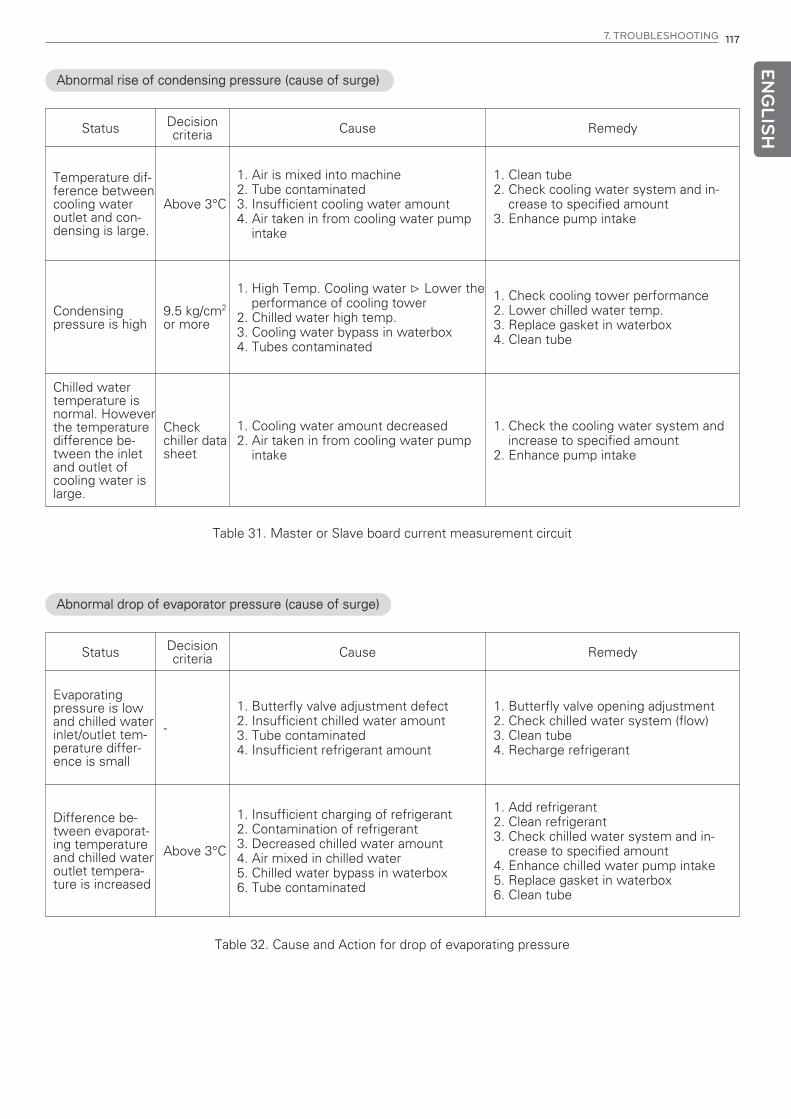
ENG
LISH
7. TROUBLESHOOTING 117
Abnormal rise of condensing pressure (cause of surge)
Status Decision criteria Cause Remedy
Temperature dif-ference betweencooling wateroutlet and con-densing is large.
Above 3°C
1. Air is mixed into machine2. Tube contaminated3. Insufficient cooling water amount4. Air taken in from cooling water pump
intake
1. Clean tube2. Check cooling water system and in-
crease to specified amount3. Enhance pump intake
Condensingpressure is high
9.5 kg/cm2
or more
1. High Temp. Cooling water ▷ Lower theperformance of cooling tower
2. Chilled water high temp.3. Cooling water bypass in waterbox4. Tubes contaminated
1. Check cooling tower performance2. Lower chilled water temp.3. Replace gasket in waterbox4. Clean tube
Chilled watertemperature isnormal. Howeverthe temperaturedifference be-tween the inletand outlet ofcooling water islarge.
Checkchiller datasheet
1. Cooling water amount decreased2. Air taken in from cooling water pump
intake
1. Check the cooling water system andincrease to specified amount
2. Enhance pump intake
Table 31. Master or Slave board current measurement circuit
Abnormal drop of evaporator pressure (cause of surge)
Status Decision criteria Cause Remedy
Evaporatingpressure is lowand chilled waterinlet/outlet tem-perature differ-ence is small
-
1. Butterfly valve adjustment defect2. Insufficient chilled water amount3. Tube contaminated4. Insufficient refrigerant amount
1. Butterfly valve opening adjustment2. Check chilled water system (flow)3. Clean tube4. Recharge refrigerant
Difference be-tween evaporat-ing temperatureand chilled wateroutlet tempera-ture is increased
Above 3°C
1. Insufficient charging of refrigerant2. Contamination of refrigerant3. Decreased chilled water amount4. Air mixed in chilled water5. Chilled water bypass in waterbox6. Tube contaminated
1. Add refrigerant2. Clean refrigerant3. Check chilled water system and in-
crease to specified amount4. Enhance chilled water pump intake5. Replace gasket in waterbox6. Clean tube
Table 32. Cause and Action for drop of evaporating pressure
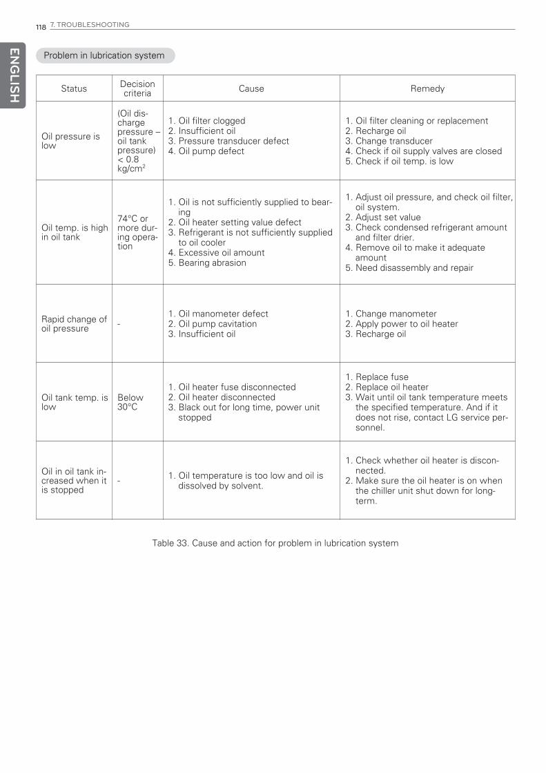
ENG
LISH
118 7. TROUBLESHOOTING
Problem in lubrication system
Status Decision criteria Cause Remedy
Oil pressure islow
(Oil dis-chargepressure –oil tankpressure)< 0.8kg/cm2
1. Oil filter clogged2. Insufficient oil3. Pressure transducer defect4. Oil pump defect
1. Oil filter cleaning or replacement2. Recharge oil3. Change transducer4. Check if oil supply valves are closed5. Check if oil temp. is low
Oil temp. is highin oil tank
74°C ormore dur-ing opera-tion
1. Oil is not sufficiently supplied to bear-ing
2. Oil heater setting value defect3. Refrigerant is not sufficiently supplied
to oil cooler4. Excessive oil amount5. Bearing abrasion
1. Adjust oil pressure, and check oil filter,oil system.
2. Adjust set value3. Check condensed refrigerant amount
and filter drier.4. Remove oil to make it adequate
amount5. Need disassembly and repair
Rapid change ofoil pressure -
1. Oil manometer defect2. Oil pump cavitation3. Insufficient oil
1. Change manometer2. Apply power to oil heater3. Recharge oil
Oil tank temp. islow
Below30°C
1. Oil heater fuse disconnected2. Oil heater disconnected3. Black out for long time, power unit
stopped
1. Replace fuse2. Replace oil heater3. Wait until oil tank temperature meets
the specified temperature. And if itdoes not rise, contact LG service per-sonnel.
Oil in oil tank in-creased when itis stopped
- 1. Oil temperature is too low and oil isdissolved by solvent.
1. Check whether oil heater is discon-nected.
2. Make sure the oil heater is on whenthe chiller unit shut down for long-term.
Table 33. Cause and action for problem in lubrication system
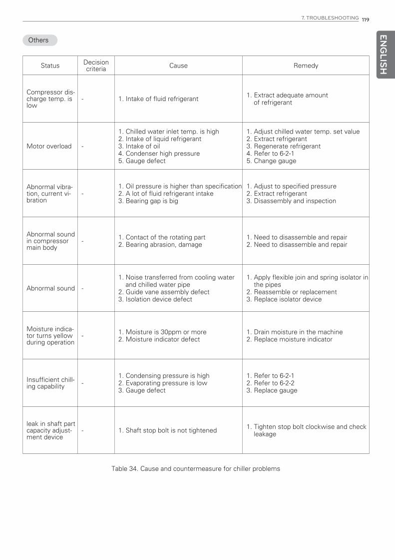
ENG
LISH
7. TROUBLESHOOTING 119
Others
Status Decision criteria Cause Remedy
Compressor dis-charge temp. islow
- 1. Intake of fluid refrigerant 1. Extract adequate amount of refrigerant
Motor overload -
1. Chilled water inlet temp. is high2. Intake of liquid refrigerant3. Intake of oil4. Condenser high pressure5. Gauge defect
1. Adjust chilled water temp. set value2. Extract refrigerant3. Regenerate refrigerant4. Refer to 6-2-15. Change gauge
Abnormal vibra-tion, current vi-bration
-1. Oil pressure is higher than specification 2. A lot of fluid refrigerant intake3. Bearing gap is big
1. Adjust to specified pressure2. Extract refrigerant3. Disassembly and inspection
Abnormal soundin compressormain body
- 1. Contact of the rotating part 2. Bearing abrasion, damage
1. Need to disassemble and repair2. Need to disassemble and repair
Abnormal sound -
1. Noise transferred from cooling waterand chilled water pipe
2. Guide vane assembly defect3. Isolation device defect
1. Apply flexible join and spring isolator inthe pipes
2. Reassemble or replacement3. Replace isolator device
Moisture indica-tor turns yellowduring operation
- 1. Moisture is 30ppm or more2. Moisture indicator defect
1. Drain moisture in the machine2. Replace moisture indicator
Insufficient chill-ing capability -
1. Condensing pressure is high2. Evaporating pressure is low3. Gauge defect
1. Refer to 6-2-12. Refer to 6-2-23. Replace gauge
leak in shaft partcapacity adjust-ment device
- 1. Shaft stop bolt is not tightened 1. Tighten stop bolt clockwise and checkleakage
Table 34. Cause and countermeasure for chiller problems

ENG
LISH
120 8. OPERATION INSPECTION RECORD
8. OPERATION INSPECTION RECORD8-1. Check list for operation record
Operation record tableMODEL :
Manufacture NO. : R-134a (1-level/2-level), R-123
Table 35. Operation record table
Measurement CategoryUnit 1 2 3 4 5 6 7 8
Hour:Min. : : : : : : : :
Chilledwater
Inlet pressure kg/cm2
Outlet pressure kg/cm2
Inlet temp. °C
Outlet temp. °C
Chilled water flow m3/h
Evapora-tor
Pressure kg/cm2
Refrigerant temp. °C
Coolingwater
Inlet pressure kg/cm2
Outlet pressure kg/cm2
Inlet temp. °C
Outlet temp. °C
Cooling W. Flow m3/h
Con-denser
Pressure kg/cm2
Refrigerant temp. °C
Oil
TANK pressure kg/cm2
PUMP pressure kg/cm2
Differential pressure kg/cm2
Temp. °C
Compres-sor
Current limit value %
Operating current A
Winding temp. °C
Temp. of Bearing °C
Discharge gas temp. °C
Vane opening %
Diffuser opening %
Others
1. Chiller start time
2. Chiller stop time
3. Maintenance issues
4. Operation time
5. Number of start-ups
6. Moisture indicator color