Embed Size (px)
DESCRIPTION
Axial flux motor design with water cooling
Citation preview
882 IEEE TRANSACTIONS ON INDUSTRY APPLICATIONS, VOL. 32, NO. 4, JULYIAUGUST 1996
ine
Federico Caricchi, Member, IEEE, Fabio Crescimbini, Member, IEEE, Fabio Mezzetti, and Ezio Santini, Member, IEEE
Abstract-The design of direct-drive wheel motors must comply with diameter restriction due to housing the motor in a wheel rim and allow the achievement of very high torque density and overload capability. Slotless axial-flux permanent magnet machines (AFPM’s) prove to be the best candidate for appli- cation in electric vehicles as direct-drive wheel motors, as in comparison with conventional machines they allow designs with higher compactness, lightness and efficiency. The paper presents a newly conceived AFPM which has a multistage structure and a water-cooled ironless stator. In the proposed new topology of the machine the space formerly occupied by the toroidal core becomes a water duct, which removes heat directly from the interior surface of the stator winding. The high efficiency of the machine cooling arrangement allows long-term 100% overload operation and great reduction of the machine weight. The multistage structure of the machine is suited to overcome the restriction on the machine diameter and meet the torque required at the wheel shaft. The paper gives guidelines for the design of a multistage AFPM with water-cooled ironless stator, and describes characteristics of a two-stage prototype machine rated 215 N.m, 1100 dmin.
I. INTRODUCTION
OR LOW-SPEED high-torque machines devoted to the use in electric vehicles as direct-drive wheel motors,
requirements such as very high torque density and overload capability severely constrain the machine design because of the restriction on the machine diameter due to housing the motor in a wheel rim. Furthermore, mounting the motor within the wheel is desirable but demands totally enclosed construction of the motor to provide protection against the environment.
Conventional machines, either ac excited or brushed dc, are ill-suited for application as direct-drive wheel motors due to their poor torque density and overload capability compared to brushless permanent magnet (PM) machines. Therefore, brushless permanent magnet motors designed for low-speed high-torque operation are emerging as the best answer to the severe requirements posed by wheel direct drive, and to date investigation on direct-drive wheel motors is developed toward novel topologies of permanent magnet machine which allow further improvements of the machine characteristics.
Paper IPCSD 96-07, approved by the Electric Machines Committee of the IEEE Industry Applications Society for presentation at the 1995 IEEE Industry Applications Society Annual Meeting, Lake Buena Vista, FL, October 8-12. Manuscript released for publication January 29, 1996.
The authors are with the Department of Electrical Engineering, University of Rome “La Sapienza,” 18-001 84 Rome, Italy.
Publisher Item Identifier S 0093-9994(96)04160-6.
The availability of high-energy permanent magnets has opened up possibilities for slotless designs of permanent magnet machines with high torque-to-weight ratio for the electric vehicle application. While slotless permanent magnet machines retain all the advantages inherent to their slotted counterparts, in addition they offer improvements in torque ripple, reduced iron losses, more efficient heat removal from the stator winding, and simple manufacturing.
Among a number of novel topologies of permanent mag- net machine being investigated, slotless axial-flux permanent magnet machines (AFPM’s) prove to be the best candidate for the application in electric vehicles, as their disc shape is well suited to the direct coupling with a wheel, and they can be designed for very high torque-to-weight ratio without loss of efficiency. In the last few years, AFPM’s have been proposed for a number of low-speed high-torque motoring applications [l], [2] , as well as for use as direct drive generators [3]-[6]. Recently, a slotless axial-flux permanent magnet motor has been utilized in a prototype of wheel direct drive for the propulsion of an electric scooter [7].
Notwithstanding the remarkable characteristics of AFPM’s, the high overload capability and totally enclosed construction needed in the electric vehicle application require a great improvement of the machine cooling, and this can be best accomplished with water-cooling of the stator winding. As a result of the latest research activities on the application of AFPM’s as direct-drive wheel motors, this paper presents a newly conceived AFPM which has multistage structure and water-cooled ironless stator. In the proposed machine arrangement the toroidal core of conventional AFPM’s is eliminated, and the stator winding consists of rhomboidal shaped coils supported by a fiber-reinforced epoxy structure. The space formerly occupied by the toroidal core becomes a water duct which removes heat directly from the interior surface of the stator winding.
The ironless arrangement of the stator winding results in very high compactness and lightness of the machine, as well as in reduction of the machine power loss. Machine losses are mostly 12R loss in the stator winding, but the high efficiency of cooling directly the winding coils by circulating water allows long-term overload operation over 100%. The multistage structure of the machine is very well suited to meet the torque required at the wheel shaft with a machine diameter restricted within the wheel rim. Further to that, since the stages of the machine may be connected either in series or parallel, for a given range of the machine speed such an additional
0093-9994/96$05.00 0 1996 IEEE
Authorized licensed use limited to: Steven Sullivan. Downloaded on March 19,2010 at 01:19:42 EDT from IEEE Xplore. Restrictions apply.

CARICCHI et al.: MULTISTAGE AXIAL-FLUX PM MACHINE FOR WHEEL DIRECT DRIVE
~
883
INTERMEDIATE ROTOR MECHANICAL COUPLMG /
EPOXY- BODY
- _ - .
MAGNET
IRONLESS WILNDXNG COIL
I COOLING DUCT
- EXTERN ROTOR
FLUX PATH
AL
Fig. 1. ironless water-cooled stator winding.
Cross section of two-stage axial-flux permanent magnet machine with
degree of freedom in the machine supply allows the use of a power converter with reduced kVA rating.
Characteristics of a multistage AFPM with water-cooled ironless stator are discussed in the following together with guidelines for the optimization of the machine design. Finally, the paper describes design and construction of a two-stage prototype machine rated 220 N.m, 1100 r/min, which has been designed for application in the propulsion system of an innovative concept city car.
11. MACHINE LAYOUT
A. Multistage Arrangement In AFPM’s, the electromagnetic torque is mainly a function
of the machine outer diameter. If the available space is too small a diameter, then the torque required at the machine shaft can be achieved by means of a multistage arrangement of the machine, as shown in Fig. 1 for a two-stage machine. In a multistage AFPM, if j is the number of stages, then the machine has j stator windings and ( j + 1) PM disc rotors. The ( j + 1) rotors share a common mechanical shaft, whereas the terminals of the j three-phase windings may be connected either in series or parallel. If the connection among the machine stages can be suitably modified during variable- speed operation, then an inverter with reduced kVA rating can be used to supply the machine.
In fact, as most PM motors, AFPM’s have excellent per- formance for constant-torque operation, but they do not lend themselves to constant-power operation because of the particu-
two stages two stages in parallel in series
1
0.75
, toraue /’
I __ I
0 0 0.5 1 .o 1.5 2 0
machine speed [P.u.]
Fig 2 Per-unit EMF and torque versus speed of a two-stage machine with switching from series to parallel of the connection between the machine stages during variable-speed operation.
larly low value of inductance which requires a large amount of current to offset the magnet flux with stator reaction flux. Thus, variable-speed operation beyond the speed at which the line-to- line motor electromotive force (EMF) gets near the inverter dc input voltage (i.e., the base speed of the motor) are generally not allowed since the maximum current which the inverter can deliver is fixed. However, for a given kVA rating of the inverter the multistage arrangement of the machine allows to extend variable-speed operation over the base speed, as shown in Fig. 2 for a two-stage machine.
Machine speeds up to the base speed are achieved with con- nection in series of the machine stages, so that the maximum current which the inverter can deliver is used to produce the rated torque of the machine. When the line-to-line motor EMF gets near the inverter dc input voltage the connection between the machine stages is switched from series to parallel by means of a contactor. As the voltage at the motor terminals suddenly reduces to a half, the dc voltage available at the inverter input can still be used to deliver the maximum current of the inverter and produce half the rated torque of the machine for machine speeds up to twice the base speed.
The described technique is suitable for use in electric vehicles with direct-drive wheel motors, since in such a motor application the rated torque of the machine is only required at low speeds, whereas a reduced torque is generally needed at the maximum speed of the vehicle. Switching the connection between the machine stages during variable-speed operation allows a reduction in the cost of the motor drive, as an inverter with kVA rating equal to the rating power of only one stage of the machine has to be used. As shown in Fig. 2, the torque- speed characteristic of a two-stage machine is a combination of two constant-torque regions, and this is very near the mechanical characteristic achieved at the wheel shaft of a conventional vehicle with a two-gears drive train powered by a thermal engine. If the machine has more than two stages (e.g., a machine with four stages), the use of multiple connections among the machine stages (i.e., the connection in series, or series-parallel, or parallel) during variable-speed operation allows a wide range of speed with reduced kVA rating needed for the supply inverter. However, while a machine with more than four stages would require a quite expensive device for commutation among possible connections of the machine
Authorized licensed use limited to: Steven Sullivan. Downloaded on March 19,2010 at 01:19:42 EDT from IEEE Xplore. Restrictions apply.
884 IEEE TRANSACTIONS ON INDUSTRY APPLICATIONS, VOL. 32, NO. 4, JULYIAUGUST 1996
stages, on the other hand, it would generally not needed to meet requirements of the electric vehicle application.
B. Water-Cooled Ironless Stator
AFPM's with multistage structure may have either iron- cored or ironless stator winding. However, in the design of direct-drive wheel motors with torque ratings over a few tens of newton meters, the machine cooling poses great problems if the winding is placed on an iron core. As high overload capability and totally enclosed construction require water- cooling of the stator winding, this can be best accomplished if an ironless arrangement of the stator winding is used.
In a multistage AFPM the flux driven by magnets passes axially from a north-pole on one rotor to a facing south-pole on the other, as shown in the preceding Fig. 1. Thus, only the external rotor discs must be made of material with good magnetic properties (typically mild steel), since they are used to provide a path for flux. The intermediate, on the other hand, are used merely for mechanical support of the magnets, and so lightweight nonmagnetic materials can be used for their construction, thus enhancing the compactness and lightness of the machine.
In an AFPM with ironless stator winding the space once occupied by the toroidal core is utilized for a toroidal duct which allows either natural or assisted circulation of water within the winding in order to remove heat from the inner surface of the winding coils. The high efficiency of such a cooling system permits totally enclosed construction of the machine and dramatically improves the machine capability for long-term overload running conditions. On the other hand, the ironless arrangement of the stator winding allow an improve- ment of the machine characteristics in terms of compactness, lightness, and efficiency.
The ironless winding requires coils lying on the transverse plane normal to axis. The active sides of the coils must lie in two separate parallel planes, in order to leave space for the cooling duct. Then, the flux driven by the magnets thus interacts with the current in the active coil sides. All forces resulting from the interaction between stator current and the rotor flux act tangentially and produce torque. Heating due to current flowing in the winding coils is removed by cooling liquid passing between the coil sides.
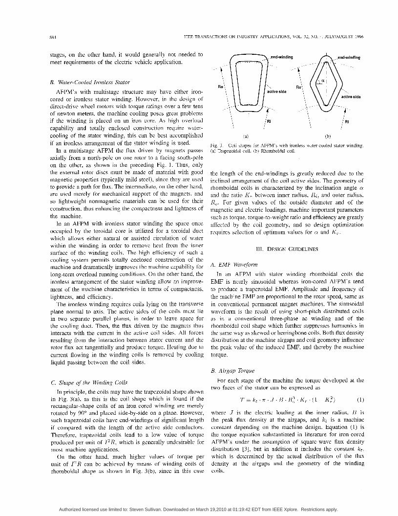
C. Shape of the Winding Coils In principle, the coils may have the trapezoidal shape shown
in Fig. 3(a), as this is the coil shape which is found if the rectangular-shape coils of an iron-cored winding are merely rotated by 90" and placed side-by-side on a plane. However, such trapezoidal coils have end-windings of significant length if compared with the length of the active side conductors. Therefore, trapezoidal coils lead to a low value of torque produced per unit of 12R, which is generally undesirable for most machine applications.
On the other hand, much higher values of torque per unit of 12R can be achieved by means of winding coils of rhomboidal shape as shown in Fig. 3(b), since in this case
't Ro \ ,,,\
1 \ IRi (a) (b)
Fig. 3. (a) Trapezoidal coil. (b) Rhomboidal coil.
Coil shapes for AFPM's with ironless water-cooled stator winding.
the length of the end-windings is greatly reduced due to the inclined arrangement of the coil active sides. The geometry of rhomboidal coils is characterized by the inclination angle Q
and the ratio K, between inner radius, Ri, and outer radius, R,. For given values of the outside diameter and of the magnetic and electric loadings, machine important parameters such as torque, torque-to-weight ratio and efficiency are greatly affected by the coil geometry, and so design optimization requires selection of optimum values for QI and K,.
111. DESIGN GUIDELINES
A. EMF Waveform
In an AFPM with stator winding rhomboidal coils the EMF is nearly sinusoidal whereas iron-cored AFPM' s tend to produce a trapezoidal EMF. Amplitude and frequency of the machine EMF are proportional to the rotor speed, same as in conventional permanent magnet machines. The sinusoidal waveform is the result of using short-pitch distributed coils as in a conventional three-phase ac winding and of the rhomboidal coil shape which further suppresses harmonics in the same way as skewed or herringbone coils. Both flux density distribution at the machine airgaps and coil geometry influence the peak value of the induced EMF, and thereby the machine torque.
B. Airgup Torque
For each stage of the machine the torque developed at the
(1)
two faces of the stator can be expressed as
T = kt . 7 r . J . B. R:. K, . (1 - K:)
where J is the electric loading at the inner radius, B is the peak flux density at the airgaps, and kt is a machine constant depending on the machine design. Equation (1) is the torque equation substantiated in literature for iron-cored AFPM's under the assumption of square-wave flux density distribution [3], but in addition it includes the constant k t , which is determined by the actual distribution of the flux density at the airgaps and the geometry of the winding coils.
Authorized licensed use limited to: Steven Sullivan. Downloaded on March 19,2010 at 01:19:42 EDT from IEEE Xplore. Restrictions apply.
CARlCCHl ef ul.: MULTISTAGE AXIAL-FLUX PM MACHINE FOR WHEEL DIRECT DRIVE
~
885
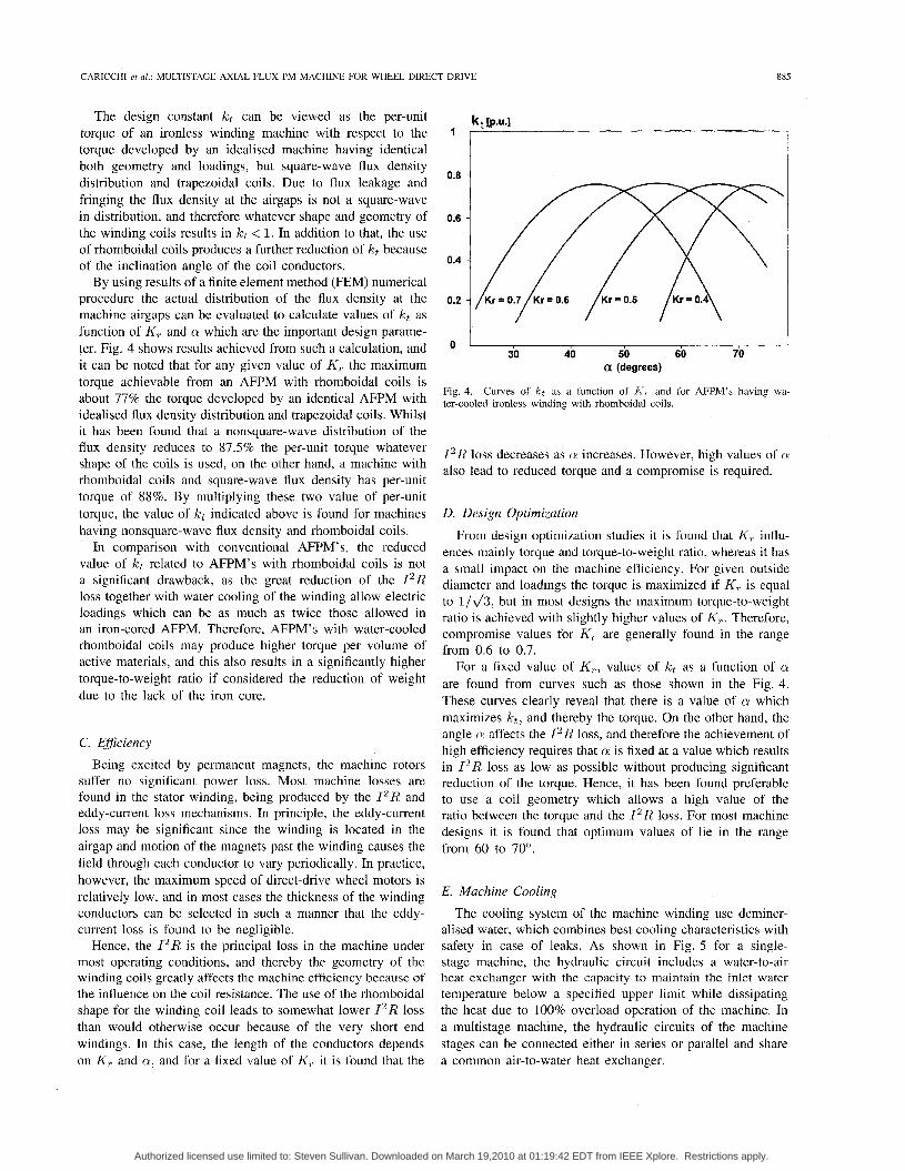
The design constant kt can be viewed as the per-unit torque of an ironless winding machine with respect to the torque developed by an idealised machine having identical both geometry and loadings, but square-wave flux density distribution and trapezoidal coils. Due to flux leakage and fringing the flux density at the airgaps is not a square-wave in distribution, and therefore whatever shape and geometry of the winding coils results in kt < 1. In addition to that, the use of rhomboidal coils produces a further reduction of kt because of the inclination angle of the coil conductors.
By using results of a finite element method (FEM) numerical procedure the actual distribution of the flux density at the machine airgaps can be evaluated to calculate values of kt as function of K, and a which are the important design parame- ter. Fig. 4 shows results achieved from such a calculation, and it can be noted that for any given value of K, the maximum torque achievable from an AFPM with rhomboidal coils is about 77% the torque developed by an identical AFPM with idealised flux density distribution and trapezoidal coils. Whilst it has been found that a nonsquare-wave distribution of the flux density reduces to 87.5% the per-unit torque whatever shape of the coils is used, on the other hand, a machine with rhomboidal coils and square-wave flux density has per-unit torque of 88%. By multiplying these two value of per-unit torque, the value of kt indicated above is found for machines having nonsquare-wave flux density and rhomboidal coils.
In comparison with conventional AFPM's, the reduced value of kt related to AFPM's with rhomboidal coils is not a significant drawback, as the great reduction of the 12R loss together with water cooling of the winding allow electric loadings which can be as much as twice those allowed in an iron-cored AFPM. Therefore, AFPM's with water-cooled rhomboidal coils may produce higher torque per volume of active materials, and this also results in a significantly higher torque-to-weight ratio if considered the reduction of weight due to the lack of the iron core.
C. Eficiency Being excited by permanent magnets, the machine rotors
suffer no significant power loss. Most machine losses are found in the stator winding, being produced by the 12R and eddy-current loss mechanisms. In principle, the eddy-current loss may be significant since the winding is located in the airgap and motion of the magnets past the winding causes the field through each conductor to vary periodically. In practice, however, the maximum speed of direct-drive wheel motors is relatively low, and in most cases the thickness of the winding conductors can be selected in such a manner that the eddy- current loss is found to be negligible.
Hence, the 12R is the principal loss in the machine under most operating conditions, and thereby the geometry of the winding coils greatly affects the machine efficiency because of the influence on the coil resistance. The use of the rhomboidal shape for the winding coil leads to somewhat lower 12R loss than would otherwise occur because of the very short end windings. In this case, the length of the conductors depends on K, and a , and for a fixed value of K, it is found that the
30 40 50 60 70 ct (degrees)
Fig. 4. ter-cooled ironless winding with rhomboidal coils.
Curves of kt as a function of IC, and for AFPM's having wa-
12R loss decreases as U increases. However, high values of a also lead to reduced torque and a compromise is required.
D. Design Optimization
From design optimization studies it is found that K, influ- ences mainly torque and torque-to-weight ratio, whereas it has a small impact on the machine efficiency. For given outside diameter and loadings the torque is maximized if K, is equal to l/&, but in most designs the maximum torque-to-weight ratio is achieved with slightly higher values of K,. Therefore, compromise values for K, are generally found in the range from 0.6 to 0.7.
For a fixed value of K,, values of kt as a function of a are found from curves such as those shown in the Fig. 4. These curves clearly reveal that there is a value of cr which maximizes k t , and thereby the torque. On the other hand, the angle a affects the 12R loss, and therefore the achievement of high efficiency requires that a is fixed at a value which results in 12R loss as low as possible without producing significant reduction of the torque. Hence, it has been found preferable to use a coil geometry which allows a high value of the ratio between the torque and the 12R loss. For most machine designs it is found that optimum values of lie in the range from 60 to 70".
E. Machine Cooling
The cooling system of the machine winding use deminer- alised water, which combines best cooling characteristics with safety in case of leaks. As shown in Fig. 5 for a single- stage machine, the hydraulic circuit includes a water-to-air heat exchanger with the capacity to maintain the inlet water temperature below a specified upper limit while dissipating the heat due to 100% overload operation of the machine. In a multistage machine, the hydraulic circuits of the machine stages can be connected either in series or parallel and share a common air-to-water heat exchanger.
Authorized licensed use limited to: Steven Sullivan. Downloaded on March 19,2010 at 01:19:42 EDT from IEEE Xplore. Restrictions apply.
886 IEEE TRANSACTIONS ON INDUSTRY APPLICATIONS, VOL. 32, NO. 4, JULY/AUGUST 1996
\-2er?- ---./
Fig. 5. Layout of the cooling system for a single-stage machine
The power loss within the winding is removed by assisted circulation of cooling water with water flow of few liters per minute. This results in a relatively low overtemperature between the inlet and the outlet of the cooling duct. The distribution of temperature around the winding follows the temperature gradient of the water along the cooling duct, but there is an overtemperature of the winding with respect to the cooling water because of the insulating enamel which coats the winding conductors.
The machine winding is hottest near the outlet of the cooling duct. For a given hydraulic radius (i.e., the thickness of the water duct), proper selection of the water flow allows over- loads along several minutes running with rise of temperature in the machine winding which keeps well below the limits allowed for the class F insulating materials used.
IV. PROTOTYPE MACHINE The ironless water-cooled stator winding arrangement dis-
cussed above is being used in the development of prototypes of multistage AFPM for application in electric vehicle drives. To date, two prototypes machine have been constructed: the first for laboratory testing, the second for installation in the propulsion drive of a concept car.
Early investigations used a single-stage 16-pole AFPM to prove the feasibility of the ironless water-cooled winding concept. Details on construction and laboratory testing of such a prototype machine were recently reported in a paper companion of this [8]. Following the successful operation of the first prototype machine, a two-stage 16-pole prototype machine has been designed for application as direct-drive wheel motor in the propulsion system of an innovative concept city car. The construction of the two-stage machine prototype has been recently completed and laboratory tests are being carried out to evaluate the machine characteristics. Thereafter, a second identical machine will be constructed to complete the propulsion system of the vehicle for a road test program.
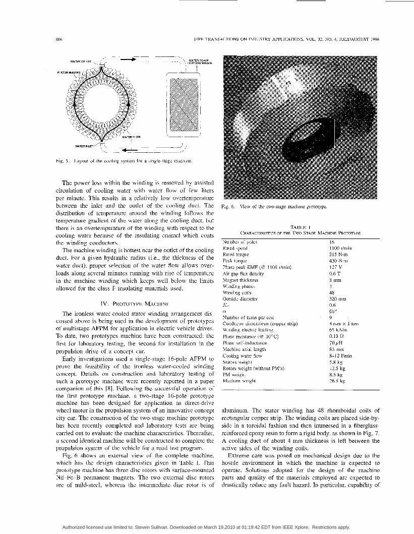
Fig. 6 shows an external view of the complete machine, which has the design characteristics given in Table I. This prototype machine has three disc rotors with surface-mounted Nd-Fe-B permanent magnets. The two external disc rotors are of mild-steel, whereas the intermediate disc rotor is of
Fig. 6. View of the two-stage machine prototype.
TABLE I CHARACTERISTICS OF THE TWO-STAGE MACHINE PROTOTYPE
Number of poles 16 Rated speed Rated torque 215 N.m Peak torque 430 N.m Phase peak EMF (@ 1100 r/min) 127 V Air gap flux density 0.6 T Magnet thickness 8 mm Winding phases 3 Winding coils 48 Outside diameter 320 mm A-,. 0.6 a 65'
Conductor dimensions (copper strip) 4 m m x l m m Winding electric loading 65 kA/m Phase resistance (@ 30OC) 0.13 0 Phase self-inductance 70 p H Machine axial length 83 mm Cooling water flow 8-12 i h i n Stators weight 5.8 kg Rotors weight (without PM's) 12.5 kg PM weight 8.5 kg Machine weight 26.8 kg
1100 r/min
Number of turns per coil 9
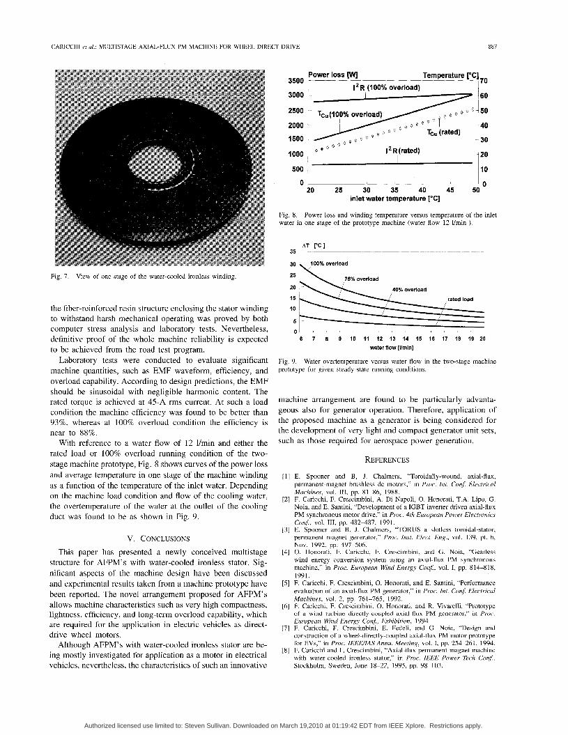
aluminum. The stator winding has 48 rhomboidal coils of rectangular copper strip. The winding coils are placed side-by- side in a toroidal fashion and then immersed in a fiberglass- reinforced epoxy resin to form a rigid body, as shown in Fig. 7. A cooling duct of about 4-mm thickness is left between the active sides of the winding coils.
Extreme care was posed on mechanical design due to the hostile environment in which the machine is expected to operate. Solutions adopted for the design of the machine parts and quality of the materials employed are expected to drastically reduce any fault hazard. In particular, capability of
Authorized licensed use limited to: Steven Sullivan. Downloaded on March 19,2010 at 01:19:42 EDT from IEEE Xplore. Restrictions apply.
CARICCHI et al.: MULTISTAGE AXIAL-FLUX PM MACHINE FOR WHEEL DIRECT DRIVE 887
Fig. 7. View of one stage of the water-cooled ironless winding.
the fiber-reinforced resin structure enclosing the stator winding to withstand harsh mechanical operating was proved by both computer stress analysis and laboratory tests. Nevertheless, definitive proof of the whole machine reliability is expected to be achieved from the road test program.
Laboratory tests were conducted to evaluate significant machine quantities, such as EMF waveform, efficiency, and overload capability. According to design predictions, the EMF should be sinusoidal with negligible harmonic content. The rated torque is achieved at 45-A rms current. At such a load condition the machine efficiency was found to be better than 93%, whereas at 100% overload condition the efficiency is near to 88%.
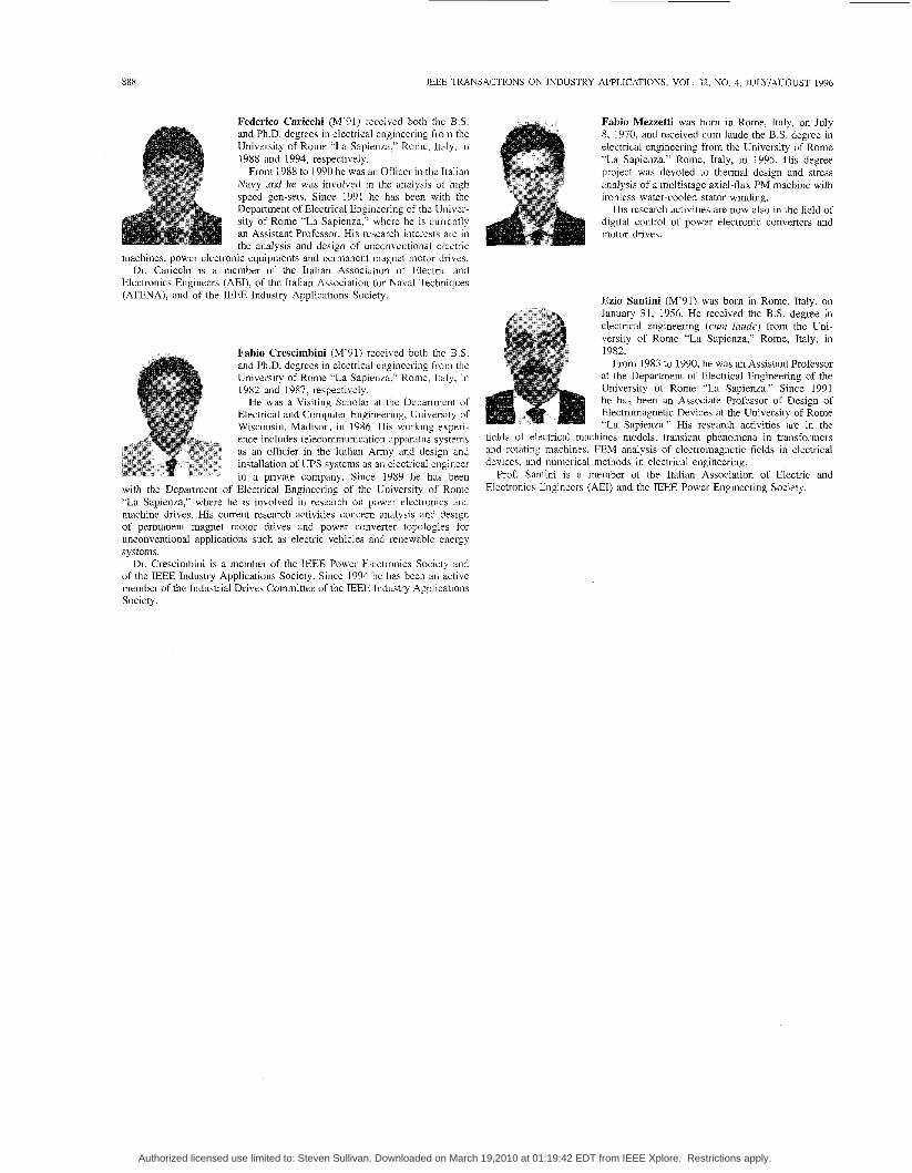
With reference to a water flow of 12 l/min and either the rated load or 100% overload running condition of the two- stage machine prototype, Fig. 8 shows curves of the power loss and average temperature in one stage of the machine winding as a function of the temperature of the inlet water. Depending on the machine load condition and flow of the cooling water, the overtemperature of the water at the outlet of the cooling duct was found to be as shown in Fig. 9.
V. CONCLUSIONS
This paper has presented a newly conceived multistage structure for AFPM’s with water-cooled ironless stator. Sig- nificant aspects of the machine design have been discussed and experimental results taken from a machine prototype have been reported. The novel arrangement proposed for AFPM’s allows machine characteristics such as very high compactness, lightness, efficiency, and long-term overload capability, which are required for the application in electric vehicles as direct- drive wheel motors.
Although AFPM’s with water-cooled ironless stator are be- ing mostly investigated for application as a motor in electrical vehicles, nevertheless, the characteristics of such an innovative
3500
3000
2500
2000
1500
Power loss [wl Temperature pC] 1 12R (100% overload) I 70
Tc,(IOO% overload) Q 0 O-50
40
30 Tcu (rated)
1000 j I*R(rated) O
500 I
0 1 0 20 25 30 35 40 45 50
inlet water temperature [‘C]
Fig 8 water in one stage of the prototype machine (water flow 12 l/min )
Power loss and winding temperature versus temperature of the inlet
~~~ - AT P C I 35 ~~
I I
I
75% overload I
40% overload
rated load
/ I 6 7 a 9 IO 11 12 13 14 IS 16 17 l a 19 20
water flow [Ih”]
I L L - ~ L l -
Fig 9. prototype for given steady-state running conditions.
Water overtemperature versus water flow in the two-stage machine
machine arrangement are found to be particularly advanta- geous also for generator operation. Therefore, application of the proposed machine as a generator is being considered for the development of very light and compact generator unit sets, such as those required for aerospace power generation.
REFERENCES
E. Spooner and B, J. Chalmers, “Toroidally-wound, axial-flux, permanent-magnet brushless dc motors,” in Proc. Int. Con$ Electrical Machines, vol. 111, pp. 81-86, 1988. F. Caricchi, F. Crescimbini, A. Di Napoli, 0. Honorati, T.A. Lipo, G. Noia, and E. Santini, “Development of a IGBT inverter driven axial-flux PM synchronous motor drive,” in Proc. 4th European Power Electronics Conf, vol. 111, pp. 482487, 1991. E. Spooner and B. J . Chalmers, “TORUS-a slotless toroidal-stator, permanent magnet generator,” Proc. Inst. Elect. Eng., vol. 139, pt. b, Nov. 1992, pp. 497-506. 0. Honorati, F. Caricchi, F. Crescimbini, and G. Noia, “Gearless wind energy conversion system using an axial-flux PM synchronous machine,” in Proc. European Wind Energy Con$, vol. I, pp. 814-818, 1991. F. Caricchi, F. Crescimbini, 0 . Honorati, and E. Santini, “Performance evaluation of an axial-flux PM generator,” in Proc. Int. Con$ Electrical Machines, vol. 2, pp. 761-765, 1992. F. Caricchi, F. Crescimbini, 0. Honorati, and R. Vivarelli, “Prototype of a wind turbine directly-coupled axial-flux PM gcncrator,” in Proc. European Wind Energy Conj, Exhibition, 1994. F. Caricchi, F. Crescimbini, E. Fedeli, and G. Noia, “Design and construction of a wheel-directly-coupled axial-flux PM motor prototype for EVs,” in Proc. IEEEIAS Annu. Meeting, vol. I, pp. 254-261, 1994. F. Caricchi and F. Crescimbini, “Axial-flux permanent-magnet machine with water-cooled ironless stator,” in Proc. IEEE Power Tech Conj, Stockholm, Sweden, June 18-22, 1995, pp. 98-103.
Authorized licensed use limited to: Steven Sullivan. Downloaded on March 19,2010 at 01:19:42 EDT from IEEE Xplore. Restrictions apply.
888 IEEE TRANSACTIONS ON INDUSTRY APPLICATIONS, VOL. 32, NO. 4, JULYIAUGUST 1996
Federico Caricchi (M’91) received both the B S and Ph D degrees in electrical engineenng from the University of Rome “La Sapienza,” Rome, Italy. in 1988 and 1994, respectively
From 1988 to 1990 he was an Officer in the Italian Navy and he was involved in the analysis of high speed gen-sets Since 1991 he has been with the Department of Electrical Engineenng of the Univer- sity of Rome “La Sapienza,” where he is currently an Assistant Professor His research interests are in
the analysis and design of unconventional electric machines, power electronic equipments and permanent magnet motor dnves
Dr Caricchi is a member of the Italian Association of Electnc and Electronics Engineers (AEI), of the Italian Association for Naval Techniques (ATENA), and of the IEEE Industry Applications Society
Fabio Crescimbini (M’91) received both the B S and Ph.D. degrees in electrical engineering from the University of Rome “La Sapienza,” Rome, Italy, in 1982 and 1987, respectively
He was a Visiting Scholar at the Department of Electrical and Computer Engineenng, University of Wisconsin, Madiqon, in 1986 His working expen- ence includes telecommunication apparatus systems as an officier in the Italian Army and design and installation of UPS systems as an electncal engineer in a private company Since 1989 he has been
with the Department of Electrical Engineering of the University of Rome “La Sapienza,” where he is involved in research on power electronics and machine drives His current research activities concern analysis and design of permanent magnet motor drives and power converter topologies for unconventional applications such as electric vehicles and renewable energy systems
Dr Crescimbmi is a member of the IEEE Power Electronics Society and of the IEEE Industry Applications Society Since 1994 he has been an active member of the Industrial Drives Committee of the IEEE Industry Applications Society
Fabio Mezzetti was born in Rome, Italy, on July 8, 1970, and received cum laude the B.S degree in electrical engineering from the University of Rome “La Sapienza,” Rome, Italy, in 1995. His degree project was devoted to thermal design and stress analysis of a multistage axial-flux PM machine with ironless water-cooled stator winding.
His research activities are now also in the field of digital control of power electronic converters and motor drives
Ezio Santini (M’91) was born in Rome, Italy, on January 31, 1956. He received the B S degree in electrical engineering (cum luude) from the Uni- versity of Rome “La Sapienza,” Rome, Italy, in 1982
From 1983 to 1990, he was an Assistant Professor at the Department of Electrical Engineering of the University of Rome “La Sapienza” Since 1991 he has been an Associate Professor of Design of Electromagnetic Devices at the university of Rome “La Sapienza” His research activities are in the
fields of electrical machines models, transient phenomena in transformers and rotating machines, FEM analysis of electromagnetic fields in electrical devices, and numencal methods in electrical engineering
Prof Santim is a member of the Italian Association of Electric and Electronics Engineers (AEI) and the IEEE Power Engineering Society
Authorized licensed use limited to: Steven Sullivan. Downloaded on March 19,2010 at 01:19:42 EDT from IEEE Xplore. Restrictions apply.