Embed Size (px)
Citation preview
State of Michigan Department of Natural Resources &
Environment
2010
TRAINING MANUAL
for
OPERATORS of
WASTEWATER STABILIZATION LAGOONS
Prepared by:
Operator Training and Certification Unit
Manual provided as part of training package. Cost of manual, other than through training program, $40.00


Introduction
INTRODUCTION
Wastewater Stabilization Lagoon Training Course Prepared By
The Operator Training and Certification Unit Michigan Department of Natural Resources & Environment
Purpose and Scope This course was developed to provide the operators of wastewater stabilization lagoon systems with the basic understanding of this treatment process as well as the requirements for operation, control, and maintenance of this type of treatment system. The purpose of the manual is to provide written material to compliment and in some cases add to the class discussions. The manual is not intended to include everything lagoon operators need to know nor be a substitute for a facility’s “Operation and Maintenance Manual”. However, we trust that the course and the manual will be valuable tools to be used by operators along with other resources, especially their work experience, to become better operators and protectors of the environment and public health. Manual Organization The manual is organized to follow the course presentation. In general it follows the normal path of wastewater after it has been discharged into the collection system. However, some topics such as the treatment process and mathematics will be covered early in the course for emphasis. Overall, a basic description of the operation and maintenance of the lift station through the stabilization lagoons is provided. Definition of a Wastewater Stabilization Lagoon For this course we will use the following definition of a wastewater stabilization lagoon: A carefully designed structure constructed to contain and to facilitate the operation and control of a complex process of treating or stabilizing wastewater. A lagoon system consists of many parts. It will have one or more, usually earthen-diked containments, constructed to hold water. Each containment may be called a lagoon, pond, or cell. The containments (with a few exceptions) are lined so that the water cannot seep into the ground uncontrolled. A system of pipes is included with appropriate valves to conduct the collected wastewater into, through, and out of the system as controlled by the operator. The size and number of ponds in these systems vary greatly depending on the amount of wastewater to be treated. Each cell may have a surface area as small as a few thousand square feet to as large as several acres. The water depth in the cells is
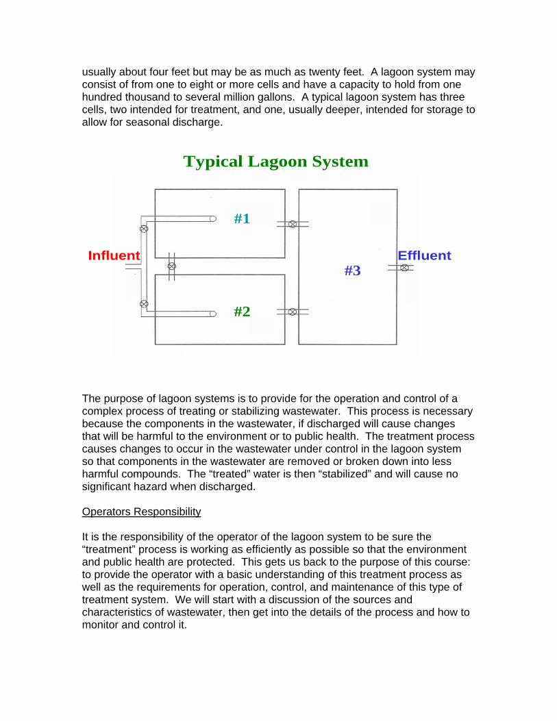
usually about four feet but may be as much as twenty feet. A lagoon system may consist of from one to eight or more cells and have a capacity to hold from one hundred thousand to several million gallons. A typical lagoon system has three cells, two intended for treatment, and one, usually deeper, intended for storage to allow for seasonal discharge.
Influent Effluent
#1
#2
#3
Typical Lagoon System
The purpose of lagoon systems is to provide for the operation and control of a complex process of treating or stabilizing wastewater. This process is necessary because the components in the wastewater, if discharged will cause changes that will be harmful to the environment or to public health. The treatment process causes changes to occur in the wastewater under control in the lagoon system so that components in the wastewater are removed or broken down into less harmful compounds. The “treated” water is then “stabilized” and will cause no significant hazard when discharged. Operators Responsibility It is the responsibility of the operator of the lagoon system to be sure the “treatment” process is working as efficiently as possible so that the environment and public health are protected. This gets us back to the purpose of this course: to provide the operator with a basic understanding of this treatment process as well as the requirements for operation, control, and maintenance of this type of treatment system. We will start with a discussion of the sources and characteristics of wastewater, then get into the details of the process and how to monitor and control it.

1. Wastewater Characteristics
CHAPTER ONE Characteristics of Wastewater
Wastewater Sources Wastewater may be described as water that is used to carry waste products away from homes, schools, commercial establishments, and industries. The wastewater comes from three general sources: domestic, industrial, and infiltration into the collection system. Domestic wastewater comes from homes, apartments, schools and the like. These flows, often called sanitary waste, contains materials from food preparation and clean-up, laundry operations, household cleaners, and of course human waste products. Just considering what may be in these flows it can be seen that they contain a wide variety of compounds, many of which are not only a nuisance, but also harmful to the environment and to human health. Discharges from industrial operations may add greatly to the number and variety of compounds in the wastewater that may not only be harmful, but also may be very difficult to remove from the flow. Even though the communities that typically use lagoon systems are relatively small and have few if any industries, just one or two can add significantly to the hazards as well as difficulty of treatment. Also, depending upon the collection system, the wastewater may become diluted with groundwater or surface water as it passes from the source to the point of treatment. This infiltration into sewage collection system may account for large increases in the amount of wastewater that requires treatment, as well as bringing in additional materials that may cause treatment problems. Although typical quantities of domestic wastewater generation are somewhat predictable, industrial contributions and infiltration rates often fluctuate greatly. All these factors taken together demonstrate that the task of the person responsible to protect the environment and the health of the public from the harmful aspects of the wastewater has a very difficult and complex job. Also, the process used to minimize these hazards has to be able to remove a wide variety of compounds, forgiving of sudden changes, resilient to toxic materials, yet capable of meeting high discharge standards.
Wastewater Characteristics
With this discussion of the sources of wastewater it would appear that the characteristics of wastewater would be considerably different for each community. Although this is true to some extent, wastewater received at treatment facilities throughout the United States, especially at the smaller communities that use lagoon systems, is quite comparable. Several general statements can be made about the “average” wastewater flows.
Quantity -The typical waste stabilization lagoon receives a flow of about 75 to 100 gallons each day for each person contributing to the collection system. This number may vary somewhat depending the amount of infiltration and the number and type of industries that are discharging to the system. However, the quantity of flow should be close to this range. If the flow increases significantly above this amount, it will result in less time for treatment of the waste and less storage capacity for the system. It is the operator’s responsibility to monitor and control the amount of wastewater coming into the lagoon system to be sure that all permit parameters are consistently being met.
Color and Odor - Typically “fresh” wastewater is cloudy or turbid, is gray in color and has a musty but not unpleasant odor. Here the term fresh means that the wastewater has traveled from the source to the lagoon system in a short enough time that significant changes have not occurred in its’ characteristics. When the wastewater is held or detained in the collection system for an extended time, any oxygen that may be in the water will be used up by chemical or biological activity. Under low oxygen (or anaerobic) conditions, further chemical or biological activity will change the compounds in the water. When this happens, the wastewater is said to be septic and becomes black with a strong, foul odor. The resulting new compounds formed under these conditions usually are a nuisance (they smell like rotten eggs), are corrosive (acidic) to equipment and the collection system, are a health hazard (toxic), and are difficult compounds for the treatment process to stabilize. Industrial discharges may also have an impact on the color and odor of the wastewater. Most of the compounds that cause these changes indicate nuisance, corrosive, hazardous, and/or treatment problems.
Temperature – The wastewater entering the lagoon system usually is a few degrees warmer than the source water supply for the community or industry served by the system. Typically the temperature of the flow into the lagoon system ranges from 45 to 70 degrees Fahrenheit. Although warmer temperatures usually result in improved treatment efficiencies, the temperature of the wastewater, unless extreme, is not a significant concern for lagoon operators because of the large volume of water in the system compared to the incoming flow and because the facility design considerations account for low temperatures.
pH - Another concern is the acid or basic characteristic of the wastewater. This
is described by a test for pH. Low pH values, 0 to 7.0 indicate acid conditions. The lower the pH number, the higher the strength of the acid. High pH values, 7 to 14, indicate the opposite of an acid, or basic conditions. The higher the pH number, the higher the strength of the base. A pH of 7.0 is neither acid nor base and is said to be neutral. Typical wastewater has a pH range of 6.8 to 7.6, or close to neutral. Although the pH in a well operating lagoon may be high because of activity in the lagoon, the influent to the system should be very close to the typical range. A high or low pH in the influent probably means septic conditions or a significant discharge from an industry. Either of these situations will most likely affect treatment processes. Lagoon system operators should be aware of the pH of the influent and take steps to identify and eliminate sources of abnormal conditions to be sure that treatment occurs at maximum efficiency.
Specific Treatment Concerns
Components in wastewater may be generally classified in several different ways.
One might refer to the pollutants in wastewater as being either inorganic or organic. Inorganic materials include sand, grit, minerals and metals, and are not biodegradable. Although some of these compounds may settle to the bottom of the lagoon and are not discharged, inorganic compounds remain basically unchanged in the treatment system. Organic materials can be thought of as those which contain carbon, originate from living plants and animals, and are usable as a food source by living organisms. Obviously that is an over-simplification, since organic substances may be synthesized commercially, and many of them may not be biodegradable. Contributors of organic pollutants include animal wastes, food processing, household wastes, and oil and grease. These are the compounds that generally have the most impact on the environment, but are also the
Chapter One Page 2 Characteristics of Wastewater
most changed or treated by the lagoon process. Solids – The material that would remain if the water from a wastewater sample
was evaporated is commonly called “Solids”. These compounds present in wastewater may be very harmful environmentally. Solids increase the amount of sedimentation in aquatic systems, choking off plants and animals and limiting the use of the receiving water. Therefore, they are very often regulated in discharges of wastewater.
The term “solids” actually includes several possible components. The term
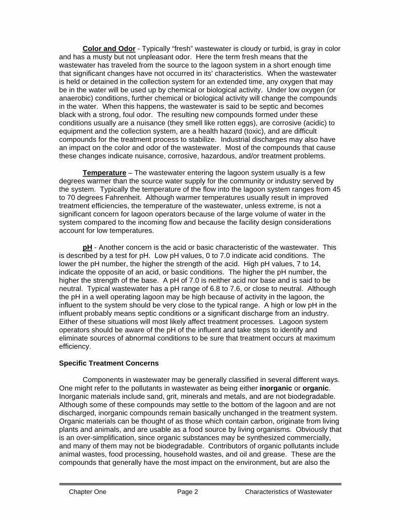
“suspended solids” refers to particles which may be visible, add turbidity, and may be filtered out. Typically, the amount of suspended solids donated to a domestic wastewater is estimated at about 0.20 to 0.22 lbs/day/capita. “Dissolved solids” are those which pass through a filter and are not seen. Only when the water is evaporated from a sample is the amount of dissolved material apparent. The term “total solids” refers to the total amount of material that would be recovered if the water was evaporated from a sample, including suspended and dissolved materials. The term “settleable solids” refers to those particulates which will settle within a defined period of time with the water not moving. Another solids term that is often used is “colloidal solids”. This refers to particles which are so finely divided that they are microscopic in size and will not settle. These give the water a cloudy or turbid appearance. Solids may be organic or inorganic. For example, table salt in water would be an inorganic, dissolved solid. Pepper in water would be an organic, suspended solid. The fraction of organic solids is often estimated by burning the material. Organic materials will burn or “volatilize” at a temperature of 550°C, while inorganic materials will remain as a residue and are referred to as “fixed”. The table on the right indicates typical solids composition of domestic wastewater.
Composition of Solids inAverage Domestic Sewage
TotalSolids
600mg/L
DissolvedSolids
400mg/L
Oxygen Demand - Many of the components of wastewater cause an oxygen
demand to occur on a wastewater treatment system or on a receiving stream. This demand occurs as microorganisms, mainly bacteria, feed on the components in the wastewater. As bacteria use the organic matter in the wastewater they require oxygen in a process called Respiration. Most of the demand occurs as a result of organic compounds, but some inorganic material, for the most part ammonia, can also contribute to the oxygen demand. As ammonia is biologically oxidized to nitrate, oxygen is used up. This process is called Nitrification.
200 mg/l
SuspendedSolids
120mg/L
80mg/L
SettleableSolids
Non-settleable
245 mg/LInorganic
300 mg/LInorganic
300 mg/LOrganic
155 mg/LOrganic
145 mg/LOrganic
55 mg/LInorganic
25 mg/L Inorganic
30 mg/L Inorganic
55 mg/L Organic
90 mg/L Organic
Chapter One Page 3 Characteristics of Wastewater
The oxygen demand of a wastewater is determined by a laboratory analysis called Biochemical Oxygen Demand (BOD). The BOD is measured by diluting a portion of the wastewater sample with specially prepared dilution water in a 300 mL BOD bottle. The initial dissolved oxygen (D.O.) concentration of the diluted sample is determined and the bottle is incubated at 20°C for 5 days. The final D.O. in the bottle is determined and the BOD of the sample is calculated based on the oxygen depletion and the amount of sample dilution.
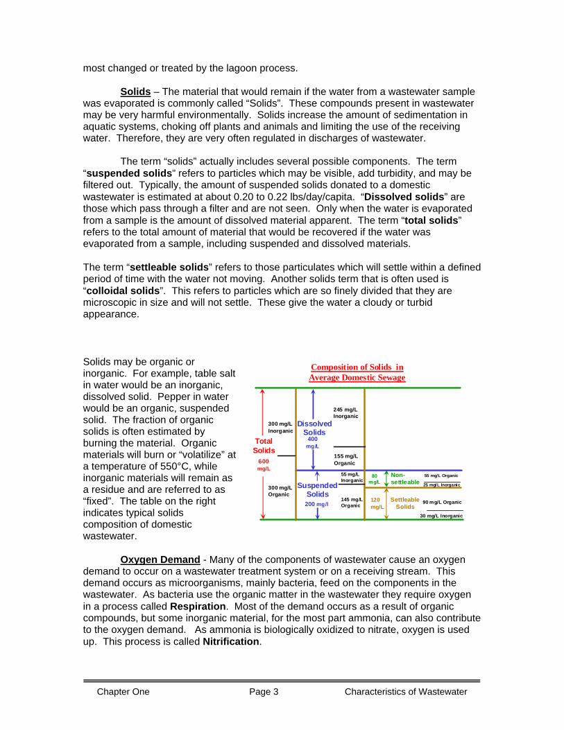
The environmental impact of BOD on a receiving stream may be illustrated with the chart below. On the left hand side of the chart, clean stream conditions are indicated by a relatively high D.O. concentration, maybe in the range of 5 - 7 mg/L and little sediment.
When a pollutant load is discharged into the stream (Zone of Degradation) the BOD concentration increases as the bacteria naturally present in the stream find a ready source of food. The bacteria become acclimated to the food supply and the population quickly increases in the Zone of Active Decomposition. In this zone oxygen consumption peaks, and the D.O. of the stream sags. Sediment increases as the pollutant is converted to bacterial mass which accumulates on the stream bottom. As the pollutant is consumed the food supply for the bacteria becomes limited. Oxygen transfer from the atmosphere overtakes oxygen consumption and the D.O. of the stream begins to increase in the Zone of Recovery. Eventually, as the BOD drops to minimal levels, the stream is
returned to Clean Stream conditions (with some additional sediment).
Sediment
DissolvedOxygen
Clea
n S t
ream
Deg
rada
tion
Reco
veryAc
tive
Dec
ompo
sitio
n
Cle
an S
trea
m
BOD
D.O.Sediment
Oxygen Sag
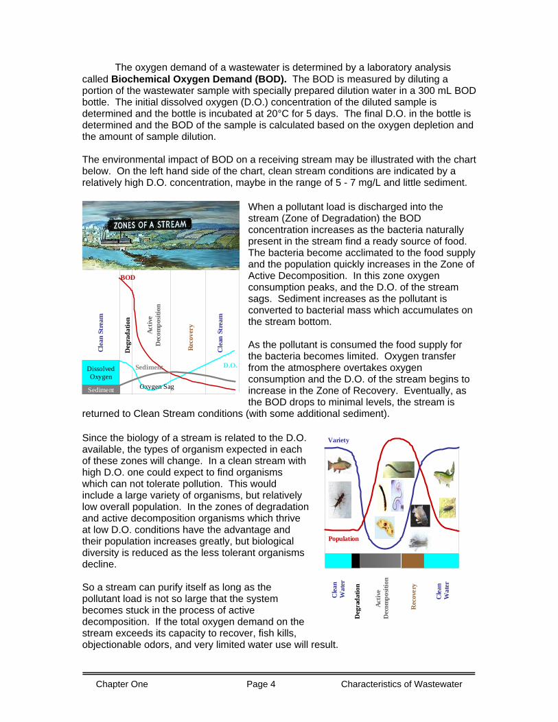
Since the biology of a stream is related to the D.O. available, the types of organism expected in each of these zones will change. In a clean stream with high D.O. one could expect to find organisms which can not tolerate pollution. This would include a large variety of organisms, but relatively low overall population. In the zones of degradation and active decomposition organisms which thrive at low D.O. conditions have the advantage and their population increases greatly, but biological diversity is reduced as the less tolerant organisms decline. So a stream can purify itself as long as the pollutant load is not so large that the system becomes stuck in the process of active decomposition. If the total oxygen demand on the stream exceeds its capacity to recover, fish kills, objectionable odors, and very limited water use will result.
Clea
n W
ater
Deg
rada
tion
Activ
eD
ecom
posit
ion
Rec
over
y
Clea
n W
ater
Population
Variety
Chapter One Page 4 Characteristics of Wastewater
This is one reason, to minimize the impact on the environment, that the treatment
process must be operated as efficiently as possible. To maintain high treatment efficiency the operator of the system must determine how much oxygen demand is coming into the system and know the limitations of the treatment system. The typical amount of BOD received at a wastewater treatment lagoon is about 0.17 to 0.22 pounds/day/capita. Although this can be used to estimate the BOD loading on a facility, it is best that actual influent samples are analyzed periodically. More will be discussed about this in the chapter on design criteria.
Nutrients - Carbon, Nitrogen and Phosphorus are nutrients that are required by
every living organism, becoming a component of every cell. Domestic wastes, animal wastes, food processing wastes, and many industrial wastes will contain these nutrients. If these are discharged into a stream or lake they act as fertilizer, increasing the growth rate of aquatic plants. As this growth rate increases the lake may become choked with weeds and the amount of sediment increases. Over time, the lake begins to fill in with sediment. Eutrophication is the term used to describe the aging process that lakes undergo as they gradually fill in with sediment, forming a bog or swamp. Careful control of the nutrient load discharged into the environment helps to slow that process. More detailed information on the impacts of nutrients and their treatment/removal will be included later.
Microorganisms – Domestic wastewater contains countless numbers of living
organisms. Most are too small to be visible except when viewed with a microscope and are therefore called ”microorganisms”. Typical domestic wastewater may contain from 100,000,000 to 1,000,000,000 microorganisms per liter. Most of these organisms are not harmful to humans and some, that will be discussed later, are actually necessary for the treatment process in lagoon systems. However, many types of microorganisms, including some bacteria and viruses, will cause diseases. These microorganisms are called pathogens. Among the diseases associated with wastewater are typhoid fever, dysentery, cholera, and hepatitis. It can be seen then, that persons involved with wastewater collection and treatment systems must be aware of the hazards to themselves while working at these facilities, but also that it is the operators responsibility to see that these pathogens are removed or destroyed before discharging in order to protect the public health. Summary Though the field of wastewater treatment has progressed by leaps and bounds in the past one hundred years, it must still be realized that the wastewater treatment plant operator has a very difficult task. Wastewater received by the treatment facility is a complex mixture of largely unknown substances which must not be released into the environment. It may include solids, oxygen demanding substances, nutrients, pathogens, and toxins. The operator should always try to bear in mind the importance of this position in the protection of natural resources and the protection of public health.
Chapter One Page 5 Characteristics of Wastewater


2. Treatment Process
CHAPTER TWO
TREATMENT PROCESS
BACKGROUND There are numerous physical, chemical, and biological processes that occur in natural bodies of water such as lakes, streams, and etc., that work together to enable them to be able to accept, stabilize, and recover from pollution loadings. However, there are limitations to the amount of pollution that can be accepted before there is damage to the environment as well as hazards to human health. It is necessary, therefore, that the wastewater from communities is collected and stabilized, or “treated”, before it is discharged to the environment. To accomplish this, so called mechanical wastewater treatment plants are designed to provide conditions under which these same natural processes of stabilization, which would otherwise occur in perhaps several miles of flowing stream, will be carried out in an environment bounded by concrete, steel, and mechanical devices. These treatment facilities are capable of handling a large amount of wastewater in a relatively small area. However, they require considerable capital to build and personnel to operate, control, and maintain and can only be supported by larger communities. Smaller communities, with limited financial resources, generally do have one advantage, the availability of land area. In those situations it becomes more economical to construct a man-made pond for the stabilization of wastewater which occurs in a natural body of water to be carried out under controlled conditions. In Michigan, many of these facilities, called wastewater stabilization lagoons, have been built. It has been proven over several years that when these facilities are properly designed and operated, they are capable of producing an effluent that is well within the standards established by governmental agencies to protect human health and the environment. Wastewater stabilization lagoons are not just "holes in the ground" as some people seem to think, but are carefully designed and constructed to do the specific job of wastewater treatment. Both the so-called conventional mechanical wastewater treatment plant and the stabilization lagoon accomplished the same end result, the protection of our natural streams and lakes from pollution and degradation from discharge of untreated sewage and industrial waste. However, both of these methods of wastewater treatment have limitations and are subject to failure by overloading, resulting in poor treatment, nuisance conditions, and hazards to human health. Even though wastewater stabilization lagoons are not as complicated to operate and control as mechanical plants, the treatment process itself is essentially the same complicated set of interactions. It is very important, therefore, that the operators have a thorough understanding of the lagoon treatment process principals and limitations to be sure the system is operated efficiently. PROCESS DESCRIPTION The “lagoon treatment process” is not just one process. As was discussed above, there are numerous processes that occur together in natural bodies of water to enable them to be able to stabilize pollution loadings. These same physical, chemical, and biological processes are involved in wastewater stabilization lagoons.
Chapter Two Page 2 Treatment Process
PHYSICAL PROCESSES There are several activities that take place in a lagoon that result in the change of state or position of the materials in the water that are related to the treatment of the wastewater. These are called physical processes. The most significant of these processes are evaporation of water to the atmosphere, seepage of water through the ground, exchange of gases into and out of the water, and sedimentation of solids down through the water. In some areas of the United States large amounts of water are lost to the atmosphere through evaporation. In these areas, lagoons are often designed to “discharge” in this way to minimize the amount discharged to surface and ground waters. In Michigan the loss by evaporation, although significant during the summer months, is almost equal to the amount gained annually through precipitation, making evaporation of little concern to the design or operation of lagoons in this area. Several lagoon systems have been designed to allow partially treated wastewater to drain or seep through the soil into the ground water. As the water goes through the soil, treatment continues in a complicated combination of physical, chemical and biological processes. Because operators of these types of systems have very little means to control or even monitor these processes, these systems increase the potential for contaminating the ground water, resulting in hazards to sources of drinking water and very costly clean-up. Therefore it is very important that these systems are properly designed and operated within design parameters. Our concern in this course is limited to activities in the ponds. Operators that are interested in seepage systems are encouraged to refer to resources that discuss soil treatment systems. The treatment of wastewater in lagoon systems involves the use of gases (primarily oxygen) and the production of gasses (primarily carbon dioxide). This will be discussed in more detail when we discuss the biological processes, but it must be kept in mind that the physical process of exchanging gasses into and out of the pond is very important to the efficient treatment of the wastewater. Anything that would reduce the ability of gasses to transfer from the water to the air or from the air to the water will affect the treatment process. It is an important part of the proper operation of a lagoon system that the ponds are kept free of floating material and other impediments to the transfer of gasses. As was seen in the discussion of the characteristics of wastewater, there are particulate solids in the un-treated wastewater. Particulate material is also produced in the chemical and biological processes that will be discussed next. These particles are removed by allowing them to settle to the bottom of the ponds. The process of the solids settling is called sedimentation and is a critical aspect of efficient treatment. Although mixing of the water in a lagoon is very important for efficient gas exchange and distribution as well as for contact between the components involved, the movement of water in the ponds must not be so great that it inhibits the settling of solids down through the water. Horizontal currents in a pond, called “short circuiting”, will carry materials through the pond and greatly reduce the treatment efficiency. Short circuiting can be caused by improper design or location of influent and effluent structures or by temperature differential between the influent flow and the water in the pond. It is very important that operators monitor the operation of the ponds to be sure that sedimentation of solids is occurring efficiently throughout the lagoon system. (We will discuss methods to correct short circuiting later in the course.) CHEMICAL PROCESSES There are several inorganic chemical reactions that occur in lagoon systems. These include chemical oxidation of sulfides, precipitation of phosphorus, and the complex relationship between carbon dioxide, carbonates, bi-carbonates, and alkalinity. Discussion of these processes is left for more advanced courses in lagoon operations. It is important, however, that lagoon operators recognize that this chemical activity occurs and must be controlled. The control of chemical processes in most lagoon systems, however, is accomplished by
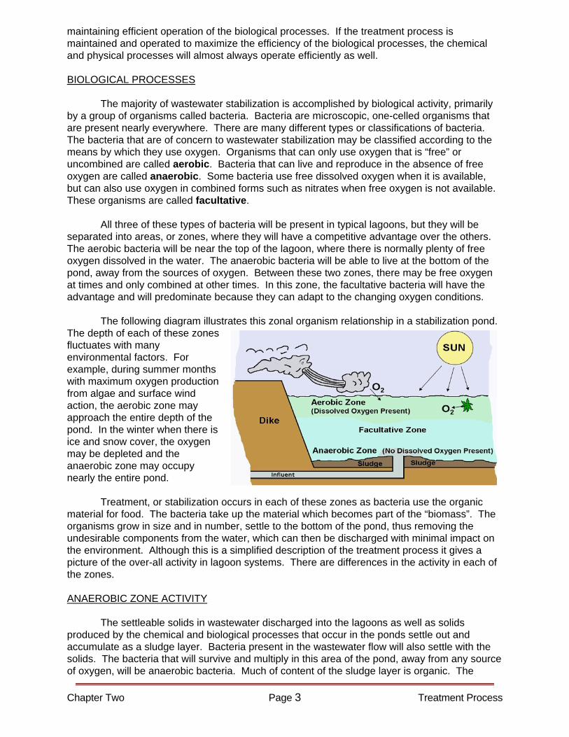
maintaining efficient operation of the biological processes. If the treatment process is maintained and operated to maximize the efficiency of the biological processes, the chemical and physical processes will almost always operate efficiently as well. BIOLOGICAL PROCESSES The majority of wastewater stabilization is accomplished by biological activity, primarily by a group of organisms called bacteria. Bacteria are microscopic, one-celled organisms that are present nearly everywhere. There are many different types or classifications of bacteria. The bacteria that are of concern to wastewater stabilization may be classified according to the means by which they use oxygen. Organisms that can only use oxygen that is “free” or uncombined are called aerobic. Bacteria that can live and reproduce in the absence of free oxygen are called anaerobic. Some bacteria use free dissolved oxygen when it is available, but can also use oxygen in combined forms such as nitrates when free oxygen is not available. These organisms are called facultative. All three of these types of bacteria will be present in typical lagoons, but they will be separated into areas, or zones, where they will have a competitive advantage over the others. The aerobic bacteria will be near the top of the lagoon, where there is normally plenty of free oxygen dissolved in the water. The anaerobic bacteria will be able to live at the bottom of the pond, away from the sources of oxygen. Between these two zones, there may be free oxygen at times and only combined at other times. In this zone, the facultative bacteria will have the advantage and will predominate because they can adapt to the changing oxygen conditions.
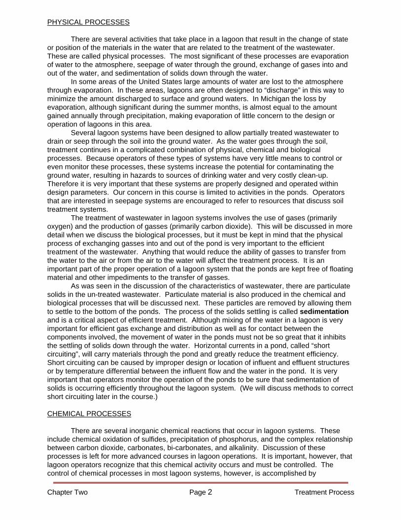
The following diagram illustrates this zonal organism relationship in a stabilization pond. The depth of each of these zones fluctuates with many environmental factors. For example, during summer months with maximum oxygen production from algae and surface wind action, the aerobic zone may approach the entire depth of the pond. In the winter when there is ice and snow cover, the oxygen may be depleted and the anaerobic zone may occupy nearly the entire pond. Treatment, or stabilization occurs in each of these zones as bacteria use the organic material for food. The bacteria take up the material which becomes part of the “biomass”. The organisms grow in size and in number, settle to the bottom of the pond, thus removing the undesirable components from the water, which can then be discharged with minimal impact on the environment. Although this is a simplified description of the treatment process it gives a picture of the over-all activity in lagoon systems. There are differences in the activity in each of the zones. ANAEROBIC ZONE ACTIVITY The settleable solids in wastewater discharged into the lagoons as well as solids produced by the chemical and biological processes that occur in the ponds settle out and accumulate as a sludge layer. Bacteria present in the wastewater flow will also settle with the solids. The bacteria that will survive and multiply in this area of the pond, away from any source of oxygen, will be anaerobic bacteria. Much of content of the sludge layer is organic. The
Chapter Two Page 3 Treatment Process
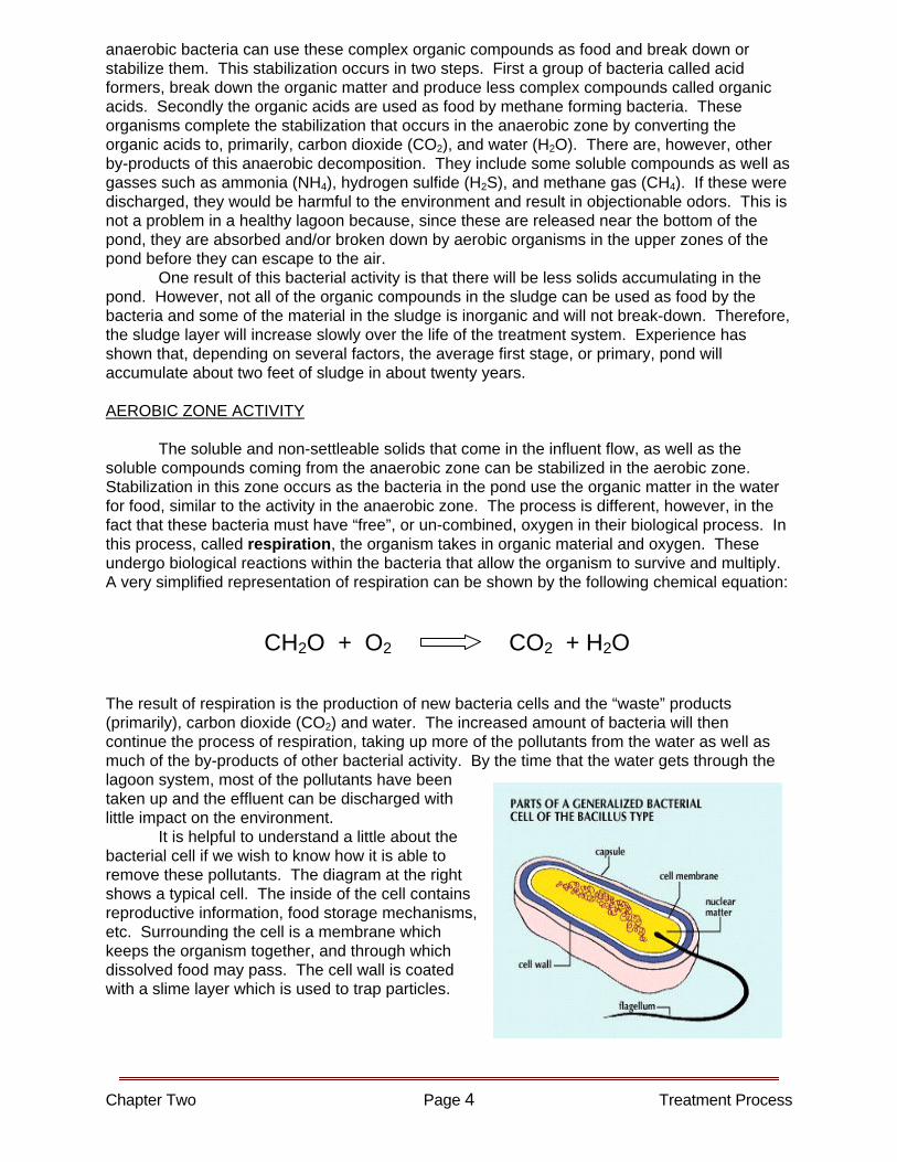
anaerobic bacteria can use these complex organic compounds as food and break down or stabilize them. This stabilization occurs in two steps. First a group of bacteria called acid formers, break down the organic matter and produce less complex compounds called organic acids. Secondly the organic acids are used as food by methane forming bacteria. These organisms complete the stabilization that occurs in the anaerobic zone by converting the organic acids to, primarily, carbon dioxide (CO2), and water (H2O). There are, however, other by-products of this anaerobic decomposition. They include some soluble compounds as well as gasses such as ammonia (NH4), hydrogen sulfide (H2S), and methane gas (CH4). If these were discharged, they would be harmful to the environment and result in objectionable odors. This is not a problem in a healthy lagoon because, since these are released near the bottom of the pond, they are absorbed and/or broken down by aerobic organisms in the upper zones of the pond before they can escape to the air. One result of this bacterial activity is that there will be less solids accumulating in the pond. However, not all of the organic compounds in the sludge can be used as food by the bacteria and some of the material in the sludge is inorganic and will not break-down. Therefore, the sludge layer will increase slowly over the life of the treatment system. Experience has shown that, depending on several factors, the average first stage, or primary, pond will accumulate about two feet of sludge in about twenty years. AEROBIC ZONE ACTIVITY The soluble and non-settleable solids that come in the influent flow, as well as the soluble compounds coming from the anaerobic zone can be stabilized in the aerobic zone. Stabilization in this zone occurs as the bacteria in the pond use the organic matter in the water for food, similar to the activity in the anaerobic zone. The process is different, however, in the fact that these bacteria must have “free”, or un-combined, oxygen in their biological process. In this process, called respiration, the organism takes in organic material and oxygen. These undergo biological reactions within the bacteria that allow the organism to survive and multiply. A very simplified representation of respiration can be shown by the following chemical equation:
CH2O + O2 CO2 + H2O The result of respiration is the production of new bacteria cells and the “waste” products (primarily), carbon dioxide (CO2) and water. The increased amount of bacteria will then continue the process of respiration, taking up more of the pollutants from the water as well as much of the by-products of other bacterial activity. By the time that the water gets through the lagoon system, most of the pollutants have been taken up and the effluent can be discharged with little impact on the environment. It is helpful to understand a little about the bacterial cell if we wish to know how it is able to remove these pollutants. The diagram at the right shows a typical cell. The inside of the cell contains reproductive information, food storage mechanisms, etc. Surrounding the cell is a membrane which keeps the organism together, and through which dissolved food may pass. The cell wall is coated with a slime layer which is used to trap particles.
Chapter Two Page 4 Treatment Process

FoodS torage
Slim e L ayer
N ew Cells The diagram at the left shows a bacterial cell suspended in wastewater containing both soluble and particulate organic pollutants. Soluble organic pollutants pass through the cell membrane (absorption) and are used as a direct food source. Particulate organics cannot pass through the membrane, but stick to the slime layer (adsorption). The organism begins to produce enzymes which are secreted through the membrane and solubilize the particulate, allowing it to pass through the membrane where it too is used as food. In this way the organism is able to remove both soluble and particulate organics from the wastewater.
Chapter Two Page 5 Treatment Process
Oxygen
S o lu ble O rg anics
CellMem b rane
NH 3CO 2H 2O
E nzym es
Wastewater
(A bs orp tio n)
A dso rbe dParticle
FACULTATIVE ZONE ACTIVITY The zone between the aerobic and anaerobic zones will at times have free oxygen available and at other times have only oxygen in combined forms such as nitrate (NO3
-). Under these changing conditions, the facultative bacteria will have the advantage and will be predominate. The biological activity of these bacteria is essentially the same as the aerobic bacteria except that they can use combined oxygen when free oxygen is not available. The importance of this zone should not be underestimated. Changes occur in each pond not only from season to season, but also from light to dark each day. Even climatic conditions such as cloud cover reducing photosynthesis or rain increasing transfer of oxygen can affect the activity in lagoons. However, even with these changing conditions, the facultative bacteria will continue the decomposition of organic compounds for a considerable time until the pond can recover aerobic conditions. Because of the importance of this zone, most non-mechanically aerated waste stabilization lagoons are called facultative lagoons. IMPORTANCE OF SUFFICIENT OXYGEN A limiting factor in obtaining efficient treatment of the influent wastewater in a lagoon system, as well as preventing objectionable odors from escaping the ponds, is providing enough dissolved oxygen (DO) to maintain an aerobic zone. Experience has shown that a pond with only facultative and anaerobic zones will soon become anaerobic throughout and will not only be unable to meet permit limits for discharge, but also produce very undesirable odor conditions. A lagoon system that is receiving a large amount of organic material will require large numbers of aerobic bacteria for efficient stabilization. These bacteria will naturally increase in numbers to meet the demand, but only if there is enough oxygen available to support them. One source of oxygen for the bacteria is from the atmosphere. The ponds used for wastewater treatment have a very large surface area for the total volume of water being treated. This allows considerable contact with the atmosphere which is made up of about 21% oxygen. Depending on a number of factors such as water temperature, considerable amounts of oxygen can dissolve into the water and be available for the bacteria. Even so, there is a very limited amount of organic material that could be treated if this was the only source of oxygen available. However, there is second way that oxygen is naturally supplied to the system. (We will discuss a way to mechanically increase the amount of oxygen transferred to the water using aeration later in the course.)
Chapter Two Page 6 Treatment Process
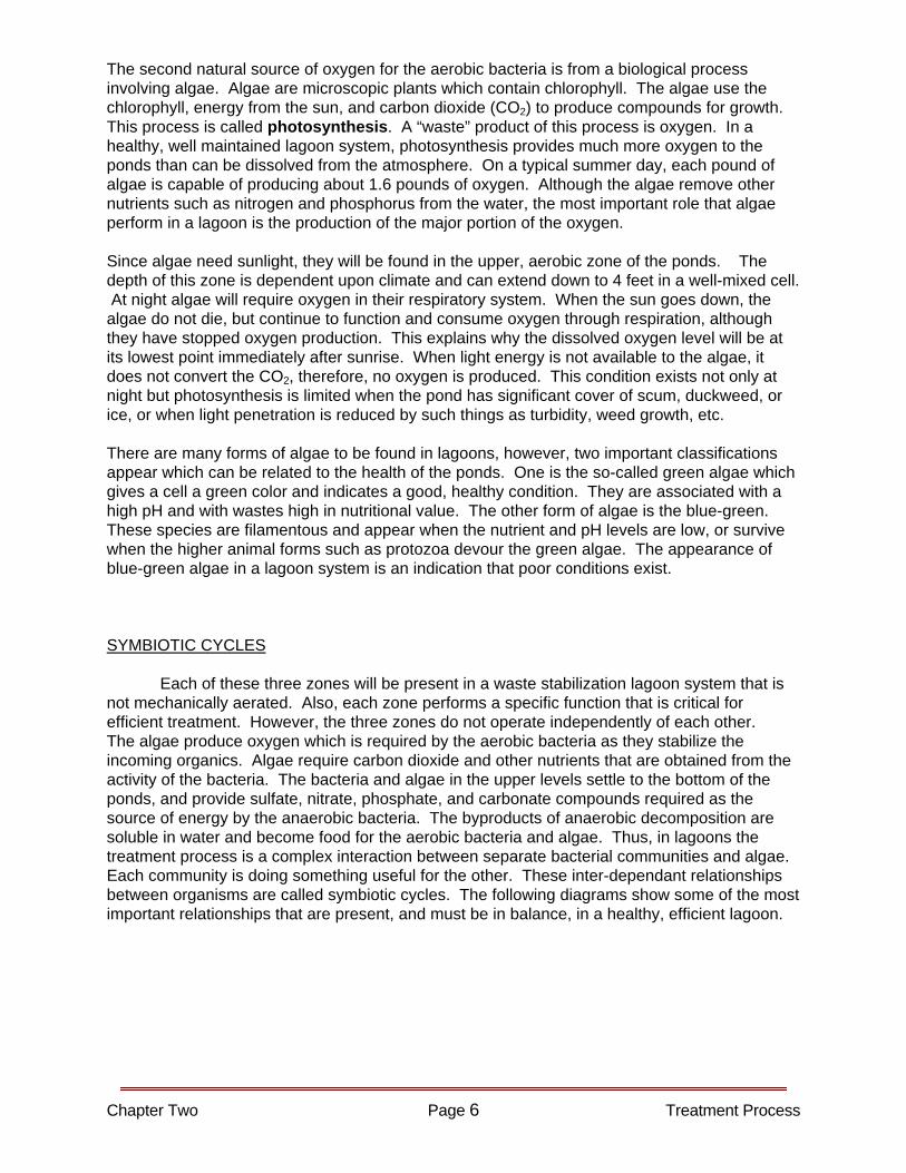
The second natural source of oxygen for the aerobic bacteria is from a biological process involving algae. Algae are microscopic plants which contain chlorophyll. The algae use the chlorophyll, energy from the sun, and carbon dioxide (CO2) to produce compounds for growth. This process is called photosynthesis. A “waste” product of this process is oxygen. In a healthy, well maintained lagoon system, photosynthesis provides much more oxygen to the ponds than can be dissolved from the atmosphere. On a typical summer day, each pound of algae is capable of producing about 1.6 pounds of oxygen. Although the algae remove other nutrients such as nitrogen and phosphorus from the water, the most important role that algae perform in a lagoon is the production of the major portion of the oxygen. Since algae need sunlight, they will be found in the upper, aerobic zone of the ponds. The depth of this zone is dependent upon climate and can extend down to 4 feet in a well-mixed cell. At night algae will require oxygen in their respiratory system. When the sun goes down, the algae do not die, but continue to function and consume oxygen through respiration, although they have stopped oxygen production. This explains why the dissolved oxygen level will be at its lowest point immediately after sunrise. When light energy is not available to the algae, it does not convert the CO2, therefore, no oxygen is produced. This condition exists not only at night but photosynthesis is limited when the pond has significant cover of scum, duckweed, or ice, or when light penetration is reduced by such things as turbidity, weed growth, etc. There are many forms of algae to be found in lagoons, however, two important classifications appear which can be related to the health of the ponds. One is the so-called green algae which gives a cell a green color and indicates a good, healthy condition. They are associated with a high pH and with wastes high in nutritional value. The other form of algae is the blue-green. These species are filamentous and appear when the nutrient and pH levels are low, or survive when the higher animal forms such as protozoa devour the green algae. The appearance of blue-green algae in a lagoon system is an indication that poor conditions exist. SYMBIOTIC CYCLES Each of these three zones will be present in a waste stabilization lagoon system that is not mechanically aerated. Also, each zone performs a specific function that is critical for efficient treatment. However, the three zones do not operate independently of each other. The algae produce oxygen which is required by the aerobic bacteria as they stabilize the incoming organics. Algae require carbon dioxide and other nutrients that are obtained from the activity of the bacteria. The bacteria and algae in the upper levels settle to the bottom of the ponds, and provide sulfate, nitrate, phosphate, and carbonate compounds required as the source of energy by the anaerobic bacteria. The byproducts of anaerobic decomposition are soluble in water and become food for the aerobic bacteria and algae. Thus, in lagoons the treatment process is a complex interaction between separate bacterial communities and algae. Each community is doing something useful for the other. These inter-dependant relationships between organisms are called symbiotic cycles. The following diagrams show some of the most important relationships that are present, and must be in balance, in a healthy, efficient lagoon.
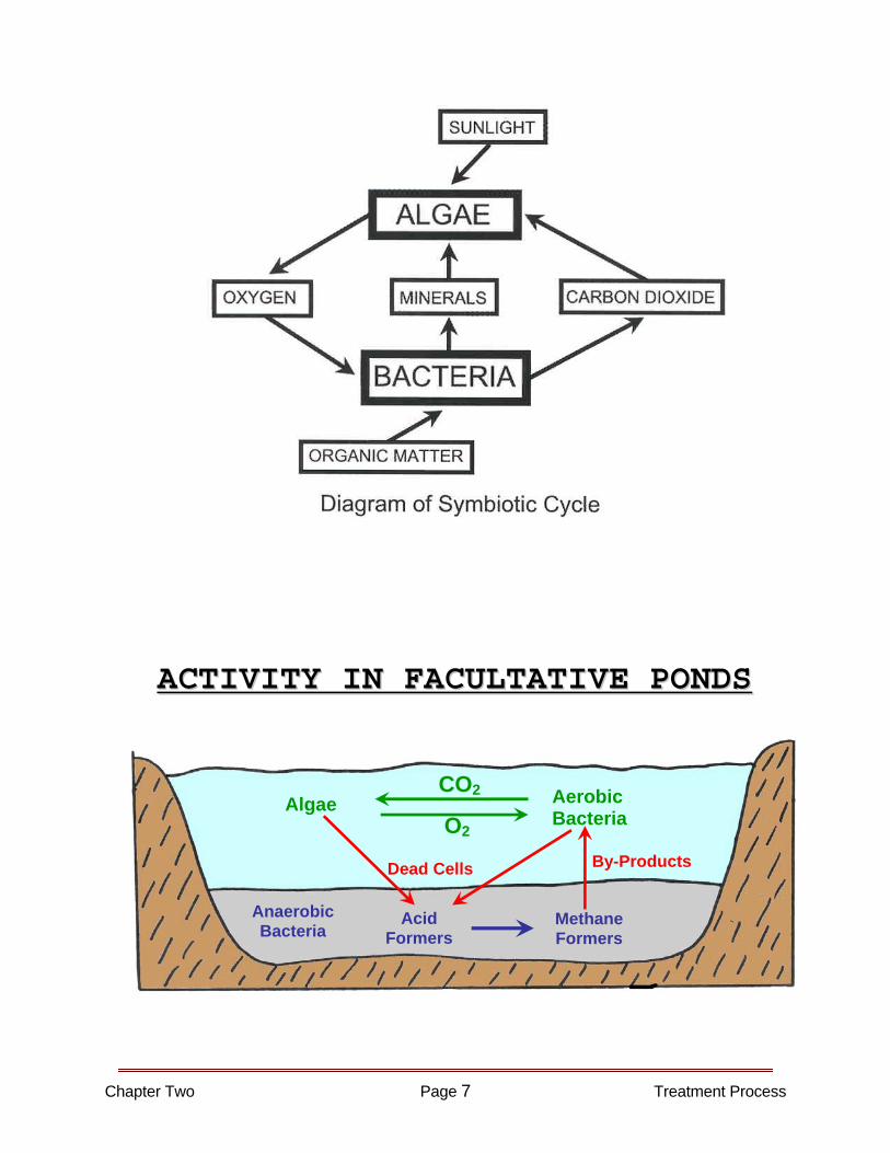
AACCTTIIVVIITTYY IINN FFAACCUULLTTAATTIIVVEE PPOONNDDSS
Anaerobic Bacteria
Acid Formers
MethaneFormers
Aerobic Bacteria
Algae O2
CO2
Dead Cells By-Products
Chapter Two Page 7 Treatment Process
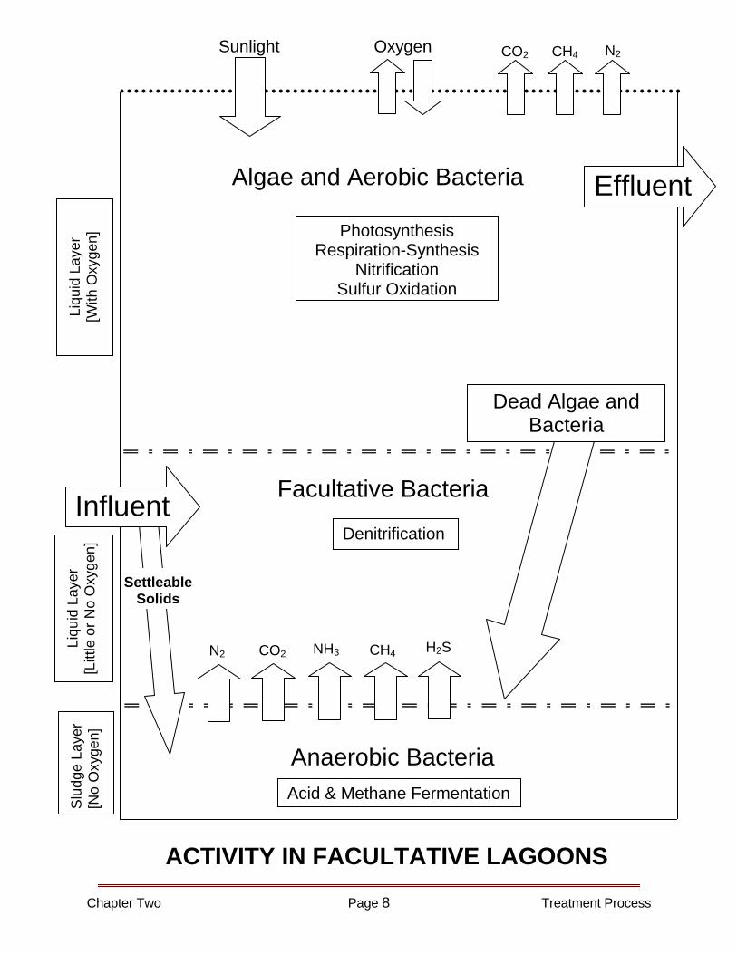
Chapter Two Page 8 Treatment Process
Settleable Solids
Influent
Effluent
Anaerobic Bacteria
Dead Algae and Bacteria
N2 CO2 NH3 CH4 H2S
Acid & Methane Fermentation
Facultative Bacteria
Algae and Aerobic Bacteria
Photosynthesis Respiration-Synthesis
Nitrification Sulfur Oxidation
Denitrification
Sunlight Oxygen N2CH4 CO2
Slu
dge
Laye
r [N
o O
xyge
n]
Liqu
id L
ayer
[L
ittle
or N
o O
xyge
n]
Liqu
id L
ayer
[W
ith O
xyge
n]
ACTIVITY IN FACULTATIVE LAGOONS
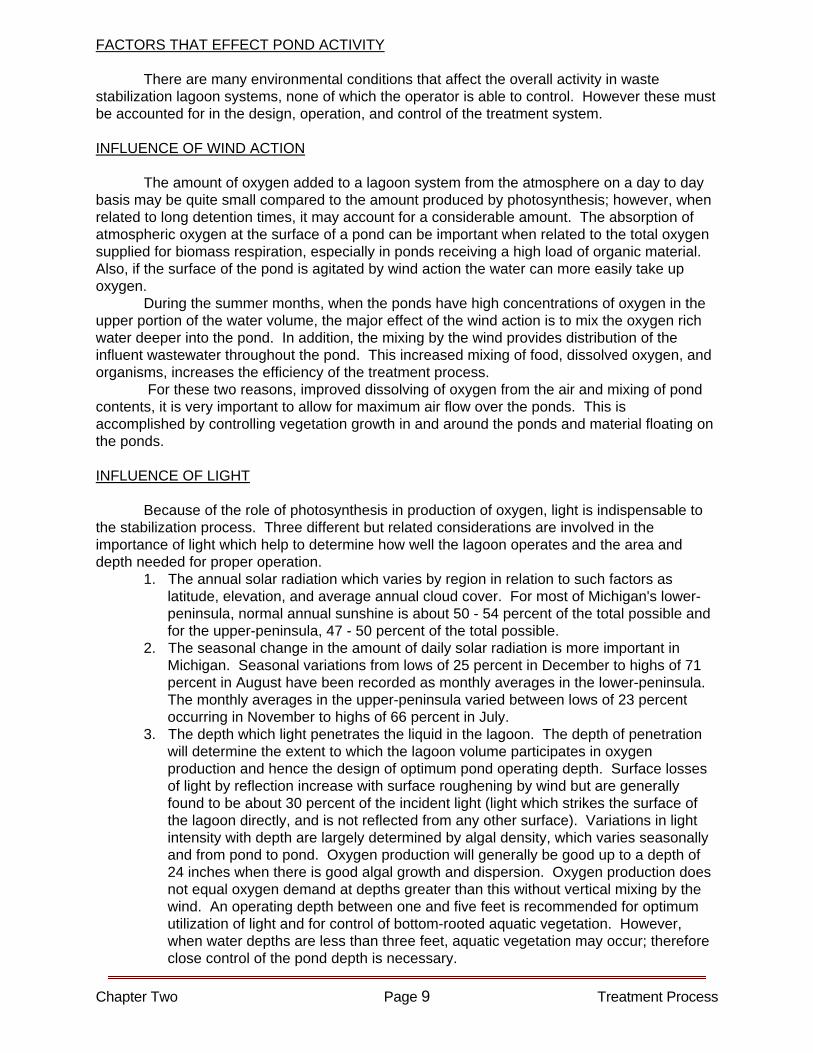
FACTORS THAT EFFECT POND ACTIVITY There are many environmental conditions that affect the overall activity in waste stabilization lagoon systems, none of which the operator is able to control. However these must be accounted for in the design, operation, and control of the treatment system. INFLUENCE OF WIND ACTION The amount of oxygen added to a lagoon system from the atmosphere on a day to day basis may be quite small compared to the amount produced by photosynthesis; however, when related to long detention times, it may account for a considerable amount. The absorption of atmospheric oxygen at the surface of a pond can be important when related to the total oxygen supplied for biomass respiration, especially in ponds receiving a high load of organic material. Also, if the surface of the pond is agitated by wind action the water can more easily take up oxygen. During the summer months, when the ponds have high concentrations of oxygen in the upper portion of the water volume, the major effect of the wind action is to mix the oxygen rich water deeper into the pond. In addition, the mixing by the wind provides distribution of the influent wastewater throughout the pond. This increased mixing of food, dissolved oxygen, and organisms, increases the efficiency of the treatment process. For these two reasons, improved dissolving of oxygen from the air and mixing of pond contents, it is very important to allow for maximum air flow over the ponds. This is accomplished by controlling vegetation growth in and around the ponds and material floating on the ponds. INFLUENCE OF LIGHT Because of the role of photosynthesis in production of oxygen, light is indispensable to the stabilization process. Three different but related considerations are involved in the importance of light which help to determine how well the lagoon operates and the area and depth needed for proper operation. 1. The annual solar radiation which varies by region in relation to such factors as
latitude, elevation, and average annual cloud cover. For most of Michigan's lower-peninsula, normal annual sunshine is about 50 - 54 percent of the total possible and for the upper-peninsula, 47 - 50 percent of the total possible.
2. The seasonal change in the amount of daily solar radiation is more important in Michigan. Seasonal variations from lows of 25 percent in December to highs of 71 percent in August have been recorded as monthly averages in the lower-peninsula. The monthly averages in the upper-peninsula varied between lows of 23 percent occurring in November to highs of 66 percent in July.
3. The depth which light penetrates the liquid in the lagoon. The depth of penetration will determine the extent to which the lagoon volume participates in oxygen production and hence the design of optimum pond operating depth. Surface losses of light by reflection increase with surface roughening by wind but are generally found to be about 30 percent of the incident light (light which strikes the surface of the lagoon directly, and is not reflected from any other surface). Variations in light intensity with depth are largely determined by algal density, which varies seasonally and from pond to pond. Oxygen production will generally be good up to a depth of 24 inches when there is good algal growth and dispersion. Oxygen production does not equal oxygen demand at depths greater than this without vertical mixing by the wind. An operating depth between one and five feet is recommended for optimum utilization of light and for control of bottom-rooted aquatic vegetation. However, when water depths are less than three feet, aquatic vegetation may occur; therefore close control of the pond depth is necessary.
Chapter Two Page 9 Treatment Process

INFLUENCE OF TEMPERATURE Temperature of the pond, as related to seasonal changes in weather, affects the lagoon treatment process mainly through the influence on the rate of bacterial activity, affecting the rate of organic material stabilization, the species and density of algae, affecting the rate of algal respiration and photosynthesis, and the dissolved oxygen saturation value. Generally, the rate of the bacterial activity, and the density and respiration rate of algae decrease with decreasing temperatures. Studies have shown that for every 10 degrees Celsius drop in water temperature, bacteriological activity decreases by 50 per cent (within the range of 5 to 30 degrees Celsius). On the other hand, the dissolved oxygen saturation value increases with decreasing temperature. For example, just before and after ice cover, the D.O. holding capacity of water may be almost twice the summertime value. As long as ice is not a barrier, surface adsorption of oxygen assumes greater importance as a mechanism for oxygen uptake and greatly helps satisfy the oxygen demands exerted during cold weather. DAILY FLUCTUATIONS Changes in solar radiation and air temperatures over a 24 hour period cause daily variations in pond temperature, dissolved oxygen concentration, pH, and other characteristics. Daily highs in dissolved oxygen may be 200 percent of saturation, while nighttime lows may approach or reach zero. Daily fluctuations of pH, reaching as high as 10 in the daytime, are related to the utilization of carbon dioxide in the process of photosynthesis. Although algae may use free carbon dioxide, it is more likely that the bulk of required carbon dioxide is obtained by the breaking down of bicarbonates resulting in the formation of carbonate which produce higher pH values.
DAILY FLUCTUATION IN A STABILIZATION POND
Chapter Two Page 10 Treatment Process
Chapter Two Page 11 Treatment Process
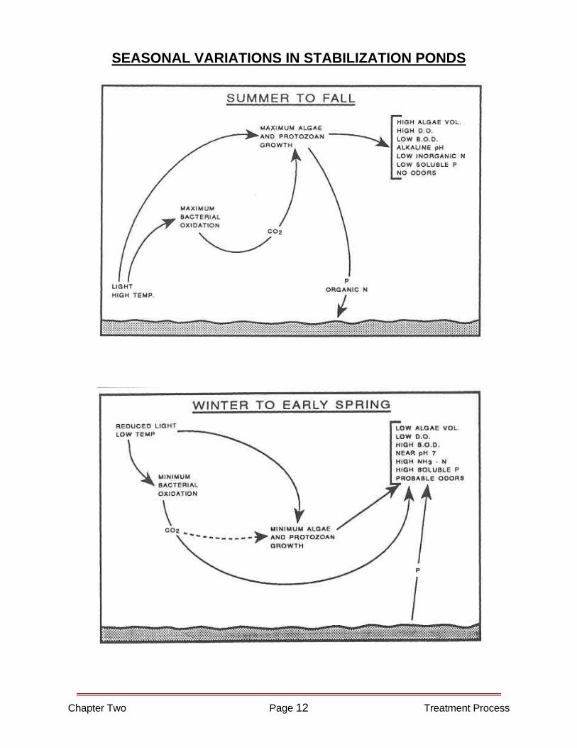
SEASONAL VARIATIONS IN STABILIZATION PONDS
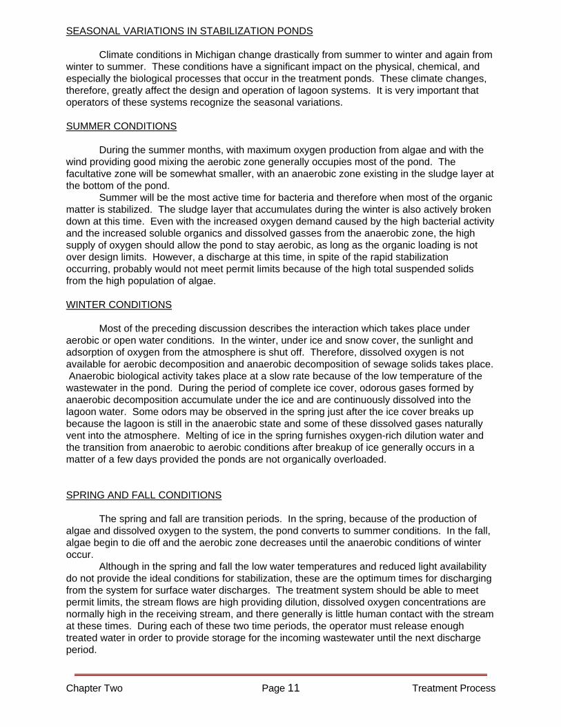
Climate conditions in Michigan change drastically from summer to winter and again from winter to summer. These conditions have a significant impact on the physical, chemical, and especially the biological processes that occur in the treatment ponds. These climate changes, therefore, greatly affect the design and operation of lagoon systems. It is very important that operators of these systems recognize the seasonal variations. SUMMER CONDITIONS During the summer months, with maximum oxygen production from algae and with the wind providing good mixing the aerobic zone generally occupies most of the pond. The facultative zone will be somewhat smaller, with an anaerobic zone existing in the sludge layer at the bottom of the pond. Summer will be the most active time for bacteria and therefore when most of the organic matter is stabilized. The sludge layer that accumulates during the winter is also actively broken down at this time. Even with the increased oxygen demand caused by the high bacterial activity and the increased soluble organics and dissolved gasses from the anaerobic zone, the high supply of oxygen should allow the pond to stay aerobic, as long as the organic loading is not over design limits. However, a discharge at this time, in spite of the rapid stabilization occurring, probably would not meet permit limits because of the high total suspended solids from the high population of algae. WINTER CONDITIONS Most of the preceding discussion describes the interaction which takes place under aerobic or open water conditions. In the winter, under ice and snow cover, the sunlight and adsorption of oxygen from the atmosphere is shut off. Therefore, dissolved oxygen is not available for aerobic decomposition and anaerobic decomposition of sewage solids takes place. Anaerobic biological activity takes place at a slow rate because of the low temperature of the wastewater in the pond. During the period of complete ice cover, odorous gases formed by anaerobic decomposition accumulate under the ice and are continuously dissolved into the lagoon water. Some odors may be observed in the spring just after the ice cover breaks up because the lagoon is still in the anaerobic state and some of these dissolved gases naturally vent into the atmosphere. Melting of ice in the spring furnishes oxygen-rich dilution water and the transition from anaerobic to aerobic conditions after breakup of ice generally occurs in a matter of a few days provided the ponds are not organically overloaded. SPRING AND FALL CONDITIONS The spring and fall are transition periods. In the spring, because of the production of algae and dissolved oxygen to the system, the pond converts to summer conditions. In the fall, algae begin to die off and the aerobic zone decreases until the anaerobic conditions of winter occur. Although in the spring and fall the low water temperatures and reduced light availability do not provide the ideal conditions for stabilization, these are the optimum times for discharging from the system for surface water discharges. The treatment system should be able to meet permit limits, the stream flows are high providing dilution, dissolved oxygen concentrations are normally high in the receiving stream, and there generally is little human contact with the stream at these times. During each of these two time periods, the operator must release enough treated water in order to provide storage for the incoming wastewater until the next discharge period.
SEASONAL VARIATIONS IN STABILIZATION PONDS
Chapter Two Page 12 Treatment Process
Chapter Two Page 13 Treatment Process
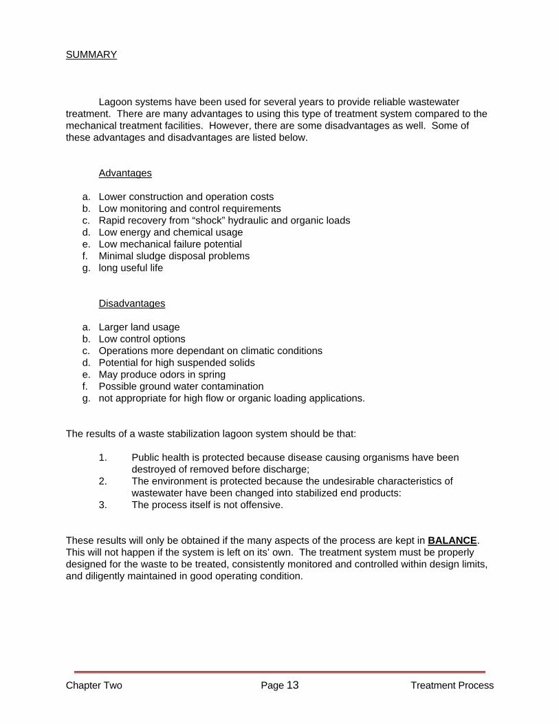
SUMMARY Lagoon systems have been used for several years to provide reliable wastewater treatment. There are many advantages to using this type of treatment system compared to the mechanical treatment facilities. However, there are some disadvantages as well. Some of these advantages and disadvantages are listed below. Advantages
a. Lower construction and operation costs b. Low monitoring and control requirements c. Rapid recovery from “shock” hydraulic and organic loads d. Low energy and chemical usage e. Low mechanical failure potential f. Minimal sludge disposal problems g. long useful life
Disadvantages
a. Larger land usage b. Low control options c. Operations more dependant on climatic conditions d. Potential for high suspended solids e. May produce odors in spring f. Possible ground water contamination g. not appropriate for high flow or organic loading applications.
The results of a waste stabilization lagoon system should be that: 1. Public health is protected because disease causing organisms have been
destroyed of removed before discharge; 2. The environment is protected because the undesirable characteristics of
wastewater have been changed into stabilized end products: 3. The process itself is not offensive. These results will only be obtained if the many aspects of the process are kept in BALANCE. This will not happen if the system is left on its’ own. The treatment system must be properly designed for the waste to be treated, consistently monitored and controlled within design limits, and diligently maintained in good operating condition.


3. Design Criteria
CHAPTER THREE
LAGOON DESIGN CRITERIA
Design criteria for waste stabilization lagoons vary, depending on experience in the various areas. There are many factors affecting lagoon operation, such as total area, loading, depth, storage capacity, and climatic conditions. Probably the most important factors affecting design of a lagoon are the waste loadings on the plant and climatic conditions for the area. The climatic conditions in Michigan dictate that the loading be less than for areas further south and west. The Great Lakes Upper Mississippi River Board of State Sanitary Engineers have published a text entitled "Recommended Standards For Sewage Works", sometimes referred to as "Ten States Standards", which includes design standards for waste stabilization lagoons. The standards are used as a guide for engineers in the design of lagoons and are used by the Michigan Department of Natural Resources & Environment in review of plans and specifications for these projects. It is not intended in this course that we become design experts. The actual design for construction or upgrade of a lagoon system should be left to the engineers with that experience and responsibility. Besides, most of us are "stuck" with facilities with the design decisions already made and in place. However, a review of some common design criteria will give an insight into the theory and operation of a lagoon. This should also be helpful in troubleshooting when problems arise as well as give some areas for consideration when looking into plant changes or upgrade. The following discussion includes some of the more important items which are considered in the design of waste stabilization lagoons. LOCATION As much consideration should be given in the location of waste stabilization lagoons as is given to the location of conventional sewage treatment plants. Much of the objection to the location of a sewage treatment facility, and particularly waste stabilization lagoons, is based on aesthetic considerations. Just as in the case of conventional plants, waste stabilization lagoons may develop odor nuisance conditions when some portion of the process is out of balance. Normally the winter to spring transition will be the only period of any noticeable odor. The duration of this period is generally less than a week, however, it may be longer when loadings are heavier than provided for in the design. Stabilization lagoons, like other wastewater treatment facilities, should be located as far from existing and future residential and commercial development as is reasonably practicable and economically feasible. It is also very important to consider the direction of prevailing winds. In Michigan, it is recommended that the lagoons be at least one-quarter mile from the existing or future residential and commercial developments in the municipality and at a minimum allowable distance of 800 feet. However, the distance to the treatment location should not be so great that detention times in the piping is excessive. This would result in septicity which adds greatly to treatment problems.
Chapter 3 2 Lagoon Design Criteria
SOIL CONDITIONS The soil at the site is important in determining the economic feasibility of lagoons. If the soil native to the site is not a fairly impervious clay, clay material or other suitable seal material may have to be used to construct the dikes and line the lagoon bottom. Location of waste stabilization lagoons in areas where fissured rock formations are near the surface of the ground should not be attempted. The lagoon bottom must be cleared of vegetation and debris. The bottom of the lagoon should be as level as possible at all points to avoid shallow areas resulting in locally unsatisfactory conditions. A slight slope to drains located at one corner or edge of cell bottom is usually provided. FENCING AND SIGNS The lagoon area shall be enclosed with a suitable fence to preclude livestock and discourage trespassing. A vehicle access gate of sufficient width to accommodate mowing equipment should be provided. All access gates should be provided with locks. Appropriate signs should be provided along the fence around the lagoon to designate the nature of the facility and forbid trespassing. The signs should be posted approximately 500 feet apart. CHARACTERISTICS OF WASTE Before the design of any pond is undertaken, it should be determined whether there are any possible toxic effects (interference with algal or bacterial growth) from the waste. Some natural water supplies may have a high sulfur content or other chemicals that limit the possibility of desired sludge decomposition. Certain wastes, such as dairy products and wine products, are difficult to treat because of their low pH. Any processing waste should be carefully investigated before one can be certain that it can be successfully treated by ponding. Some process wastes contain powerful fungicides and disinfectants that may have a great inhibitive effect on the biological activity in a pond. HEADWORKS AND SCREENING A headworks with a bar screen is desirable to remove rags, bones, and other large objects that might lodge in pipes or control structures. A trash shredder is a luxury that may not be warranted. Any material that gets past an adequate bar screen will in all probability not harm the influent pump. Any fecal matter will be pulverized in going through the pump. Provision should be made for sampling of influent flows. Consideration should also be given to providing for the ability to feed chemicals for such things as odor control. FLOW MEASURING DEVICES It is highly desirable that an influent measuring device be installed to give a direct reading on the daily volume of wastes that are introduced into the ponds. This information is necessary to calculate the hydraulic loading and storage capacity for the treatment
Chapter 3 3 Lagoon Design Criteria
system. It is also required, along with a BOD measurement of the influent, to calculate the organic loading on the pond. Influent flow volumes may also be used to monitor pump efficiencies, detect increases in infiltration, and to determine chemical feed rates. Comparison of influent and effluent flow rates is necessary for estimating percolation and evaporation losses. A measuring device provides basic data for prediction of future plant expansion needs or for detecting unauthorized or abnormal flows. Reliable, well-kept records on flow volume help justify budgets and greatly assist an engineer's design of a plant expansion or new installation. Effluent measuring is required by the discharge permit. It is also very important for plant control as well as monitoring environmental impact. INLET AND OUTLET STRUCTURES Inlet structures should be simple and foolproof and should be standard manufactured articles so that replacement parts are readily available. Telescoping friction fit tubes for regulating spill or discharge height should be avoided because a biological growth may become attached and prevent the tubes from telescoping if they are not cleaned regularly. A submerged inlet will minimize the occurrence of floating material and will help conserve the heat of the pond by introducing the warmer wastewater into the depths of the pond. Warm wastewater introduced at the bottom of a cold water mass will channel to the surface and spread unless it is promptly and vigorously mixed with cold water. Warm wastewater spilled onto the surface of the pond will spread out in a thin layer on the surface and not contribute to the warmth of the lower regions of the pond where heat is needed for bacterial decomposition. Inlet and outlet structures should be so located in relation to each other to minimize possible short circuiting. Valves that have stems extending into the stream flow should be avoided. Stringy material and rags will collect and form an obstruction and may render the valve inoperative. Free over-falls at the outlet should be avoided to minimize release of odors, foaming, and gas entrapment which may hamper pipe flows. Free over-falls should be converted to submerged outfalls if they are causing nuisances and other problems. If a pond has a surface outlet, floating material can be kept out of the effluent by building a simple baffle around the outlet. The baffle can be constructed of wood or other suitable material. It should be securely supported or anchored. DIKE SLOPES The selection of the steepness of the dike slope must depend on several variables. A steep slope erodes quicker from wave wash unless the dike is protected by riprap, especially on larger ponds. However, a steep slope minimizes waterline weed growth. It is more difficult to operate equipment and to perform routine maintenance on steep slopes. A gentle slope will erode the least from wave wash, is easier to operate equipment on, and is easier to perform routine maintenance on. However, waterline weed growth will have a much greater opportunity to flourish.
Chapter 3 4 Lagoon Design Criteria
POND DEPTHS The operational depth of ponds deserves considerable attention. Depending upon conditions, ponds of less than three feet of depth may be completely aerobic if there are no solids on the bottom (unlikely) because of the depth of sunlight penetration. This means that the treatment of wastes is accomplished essentially by converting the wastes to algae cell material. Ponds of this shallow depth are apt to be irregular in performance because algae blooms will increase to such proportions that a mass die-off will occur with the result of all algae precipitating to the bottom and thereby adding to the organic load. Such conditions could lead to the creation of an anaerobic pond. The bottoms of shallow ponds will become anaerobic when solids collect on the bottom and after sunset. Discharges from shallow, aerobic ponds contain large amounts of algae. To operate efficiently these ponds should have some means of removing the algae grown in the pond before the effluent is discharged to the receiving waters. If the algae are not removed from the effluent, the organic matter in the wastewater is not removed or treated and the problem is merely transferred to some downstream pool. An observed phenomenon of lightly loaded, shallow secondary ponds and tertiary ponds is that they are apt to become infested with filamentous algae and mosses that not only limit the penetration of sunlight into the pond but hamper circulation of the pond's contents and clog up inlet and outlet structures. When the loading is increased, this condition improves. Pond depths of four feet or more allow a greater conservation of heat from the incoming wastes to foster biological activity as the ratio between pond volume and pond area is more favorable. In facultative ponds, depths over four feet provide a physical storage for dissolved oxygen accumulated during the day to carry over through the night when no oxygen is released by the algae, unless floating algae and poor circulation keep all the oxygen near the surface. This physical storage of DO is very important during the colder months when nights are long. A pond operating depth of at least three feet is recommended to prevent the growth of cattail and other aquatic weeds. Ponds less than three feet deep should be lined to prevent troublesome weed growth. Weeds that emerge along the shore line can be effectively controlled by spraying with any of several products available. MULTIPLE CELLS Treatment usually occurs in two or more ponds called cells. These cells are generally arranged in series with water flowing from one cell into another. For example, a stabilization pond influent may enter a primary cell, then flow into a secondary cell, then into a polishing or storage cell. Many systems are arranged so that two or more primary cells can receive the plant flow. In these cases, the plant flow enters a distribution manhole or a box which is gated or valved to divide and direct the flow into both primary cells. This is called parallel operation. Effluent from these cells then follows the usual series pattern to obtain maximum solids and algae removal prior to discharge. In many systems the influent flow may be diverted to one primary cell, then to the second, providing series operation. From an operational viewpoint, series operation tends to minimize the amount of algae in the last cell and normally will provide the best treatment if the actual loading is below the design loading limits. Parallel operation for the primary cells is most often practiced when loadings exceed the design
Chapter 3 5 Lagoon Design Criteria
limits for one cell and for winter operation when ice cover develops and treatment activity is low. The design of systems with multiple cells should consider providing the necessary piping arrangement to allow the operator the maximum flexibility to exercise the options that would provide the maximum degree of treatment under changing conditions. Without this flexibility of being able to move water around where it is needed the operator would be severely handicapped. Examples of conditions that would require exercising these options include: 1. May need to hold wastewater in the primary cell, especially during seasonal
discharge operations. 2. May need to move water from cell to cell to correct an oxygen deficiency problem. 3. May need to control liquid depth to get rid of weeds or mosquitoes. 4. May need to isolate a cell that has turned anaerobic or to hold a toxic waste. 5. May need to take advantage of both series and parallel operation to regulate
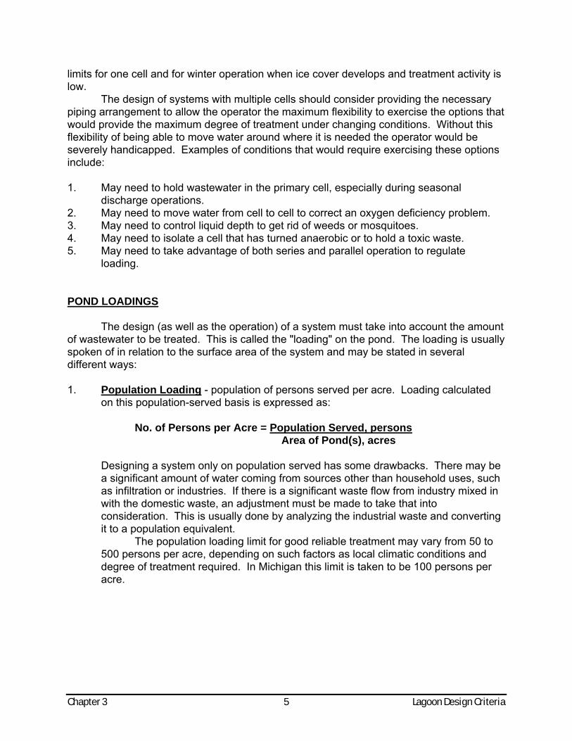
loading. POND LOADINGS The design (as well as the operation) of a system must take into account the amount of wastewater to be treated. This is called the "loading" on the pond. The loading is usually spoken of in relation to the surface area of the system and may be stated in several different ways: 1. Population Loading - population of persons served per acre. Loading calculated
on this population-served basis is expressed as: No. of Persons per Acre = Population Served, persons Area of Pond(s), acres Designing a system only on population served has some drawbacks. There may be
a significant amount of water coming from sources other than household uses, such as infiltration or industries. If there is a significant waste flow from industry mixed in with the domestic waste, an adjustment must be made to take that into consideration. This is usually done by analyzing the industrial waste and converting it to a population equivalent.
The population loading limit for good reliable treatment may vary from 50 to 500 persons per acre, depending on such factors as local climatic conditions and degree of treatment required. In Michigan this limit is taken to be 100 persons per acre.
Chapter 3 6 Lagoon Design Criteria
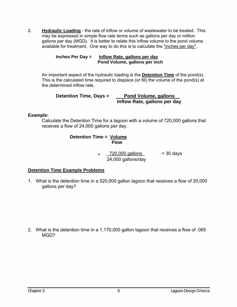
2. Hydraulic Loading - the rate of inflow or volume of wastewater to be treated. This may be expressed in simple flow rate terms such as gallons per day or million gallons per day (MGD). It is better to relate this inflow volume to the pond volume available for treatment. One way to do this is to calculate the "inches per day".
Inches Per Day = Inflow Rate, gallons per day Pond Volume, gallons per inch
An important aspect of the hydraulic loading is the Detention Time of the pond(s). This is the calculated time required to displace (or fill) the volume of the pond(s) at the determined inflow rate.
Detention Time, Days = Pond Volume, gallons . Inflow Rate, gallons per day
Example: Calculate the Detention Time for a lagoon with a volume of 720,000 gallons that receives a flow of 24,000 gallons per day.
Detention Time = Volume Flow
= 720,000 gallons . = 30 days 24,000 gallons/day Detention Time Example Problems 1. What is the detention time in a 520,000 gallon lagoon that receives a flow of 20,000
gallons per day? 2. What is the detention time in a 1,170,000 gallon lagoon that receives a flow of .065
MGD?

Chapter 3 7 Lagoon Design Criteria
3. What is the detention time in a 6,750,000 gallon storage pond that receives a flow of 45,000 gallons per day?
4. What is the detention time in a 432,000 gallon lagoon that receives a flow of .012
MGD?
The necessary detention time may vary from 30 to 120 days, again depending on climate and treatment requirements to be met.
Since treatment efficiency in lagoon systems is greatly reduced during winter, many are designed to be large enough to store the entire flow for this period. This allows for discharge when the waste has had the maximum treatment and when there is minimal impact on the receiving stream because of higher flows etc. When this "seasonal discharge" is required, the Design Storage must be considered. The calculation for Design Storage is the same as for Detention Time, except the bottom two feet of the pond(s) is not included in the storage capacity. This difference gives a minimum liquid level of two feet after discharge to allow for sludge storage, to discourage weed growth, and to prevent odors from exposed solids. The design storage limit for seasonal discharge systems in Michigan is 180 days.
It is very important to calculate the ponds detention time and the system design storage regularly. The storage capacity should be determined after every discharge to be sure there is enough holding capacity to reach the next discharge period. We suggest that these calculations be done each month using the average flow data from the monthly reports.
Of course the value of these calculations is only as good as the influent flow measurement reliability. We discuss various ways to determine influent flow in another part of the course, however one of the most common ways at lagoon facilities is to use the length of time the influent pump is on and the actual output rate of the pump. Following are example calculations using this information to determine the amount of water being pumped in the treatment system.

Chapter 3 8 Lagoon Design Criteria
Flow Rate Example Problems 1. A pump rated at 125 gpm was on for 50 minutes. How much water was pumped in gallons? 2. A pump rated at 150 gpm was on for 3 hours. How much water was pumped in gallons? 3. A pump rated at 150 cfm was on for 250 minutes. How much water was pumped in gallons?
Chapter 3 9 Lagoon Design Criteria
(Flow Rate Example Problems, Continued) 4. A pump rated at 250 gpm was on for 450 minutes. How much water was pumped in gallons? 5. A pump rated at 50 gpm was on for 9 hours. How much water was pumped in gallons? 6. A pump rated at 20 cfm was on for 125 minutes. How much water was pumped in gallons?
3. Organic Loading - the amount of organic or "biodegradable" waste that enters the system. The organics in the waste is measured by the laboratory test called the Biochemical Oxygen Demand (BOD). The organic loading is the pounds of BOD per day per acre of pond surface area.
Organic Loading = BOD, pounds per day Pond Area, acres
Typical organic loadings for facultative ponds may range from 10 to 50 pounds BOD
per day per acre. In Michigan the limit is 20 pounds per day per acre for the entire system. However, any single cell should not exceed a loading of 35 pounds per day per acre.
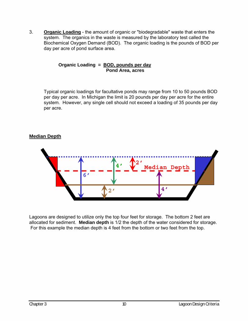
Median Depth
Chapter 3 10 Lagoon Design Criteria
6’
2’
4’
Lagoons are designed to utilize only the top four feet for storage. The bottom 2 feet are allocated for sediment. Median depth is 1/2 the depth of the water considered for storage. For this example the median depth is 4 feet from the bottom or two feet from the top.
2’Median Depth
4’
Chapter 3 11 Lagoon Design Criteria
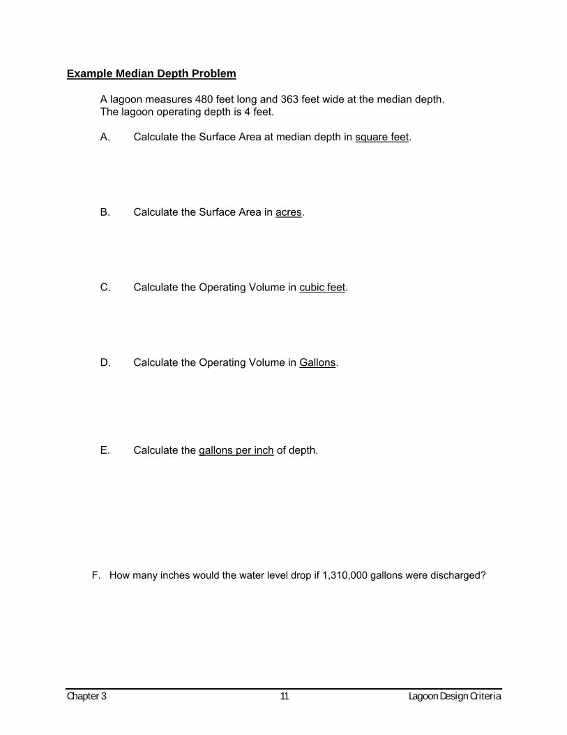
Example Median Depth Problem
A lagoon measures 480 feet long and 363 feet wide at the median depth. The lagoon operating depth is 4 feet.
A. Calculate the Surface Area at median depth in square feet.
B. Calculate the Surface Area in acres. C. Calculate the Operating Volume in cubic feet. D. Calculate the Operating Volume in Gallons. E. Calculate the gallons per inch of depth.
F. How many inches would the water level drop if 1,310,000 gallons were discharged?
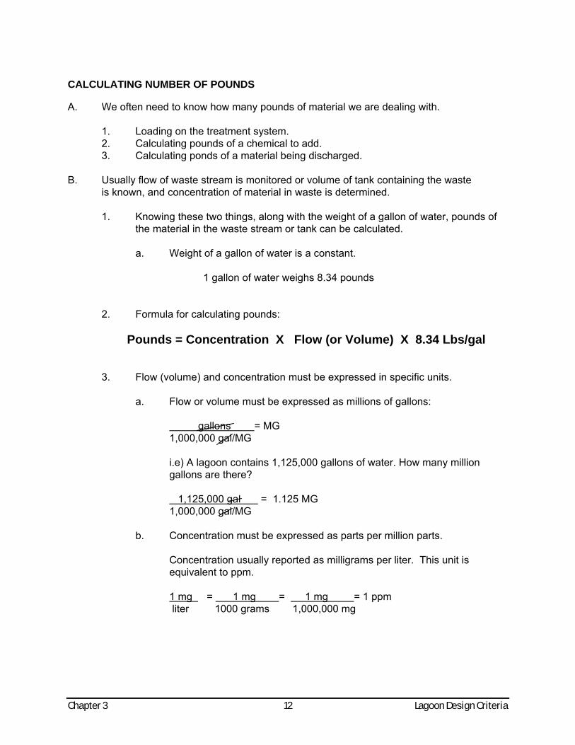
CALCULATING NUMBER OF POUNDS A. We often need to know how many pounds of material we are dealing with.
1. Loading on the treatment system. 2. Calculating pounds of a chemical to add. 3. Calculating ponds of a material being discharged.
B. Usually flow of waste stream is monitored or volume of tank containing the waste
is known, and concentration of material in waste is determined. 1. Knowing these two things, along with the weight of a gallon of water, pounds of
the material in the waste stream or tank can be calculated.
a. Weight of a gallon of water is a constant.
1 gallon of water weighs 8.34 pounds
2. Formula for calculating pounds:
Pounds = Concentration X Flow (or Volume) X 8.34 Lbs/gal
3. Flow (volume) and concentration must be expressed in specific units.
a. Flow or volume must be expressed as millions of gallons:
gallons = MG 1,000,000 gal/MG
Chapter 3 12 Lagoon Design Criteria
i.e) A lagoon contains 1,125,000 gallons of water. How many million gallons are there? 1,125,000 gal = 1.125 MG 1,000,000 gal/MG
b. Concentration must be expressed as parts per million parts.
Concentration usually reported as milligrams per liter. This unit is equivalent to ppm. 1 mg = 1 mg = 1 mg = 1 ppm liter 1000 grams 1,000,000 mg
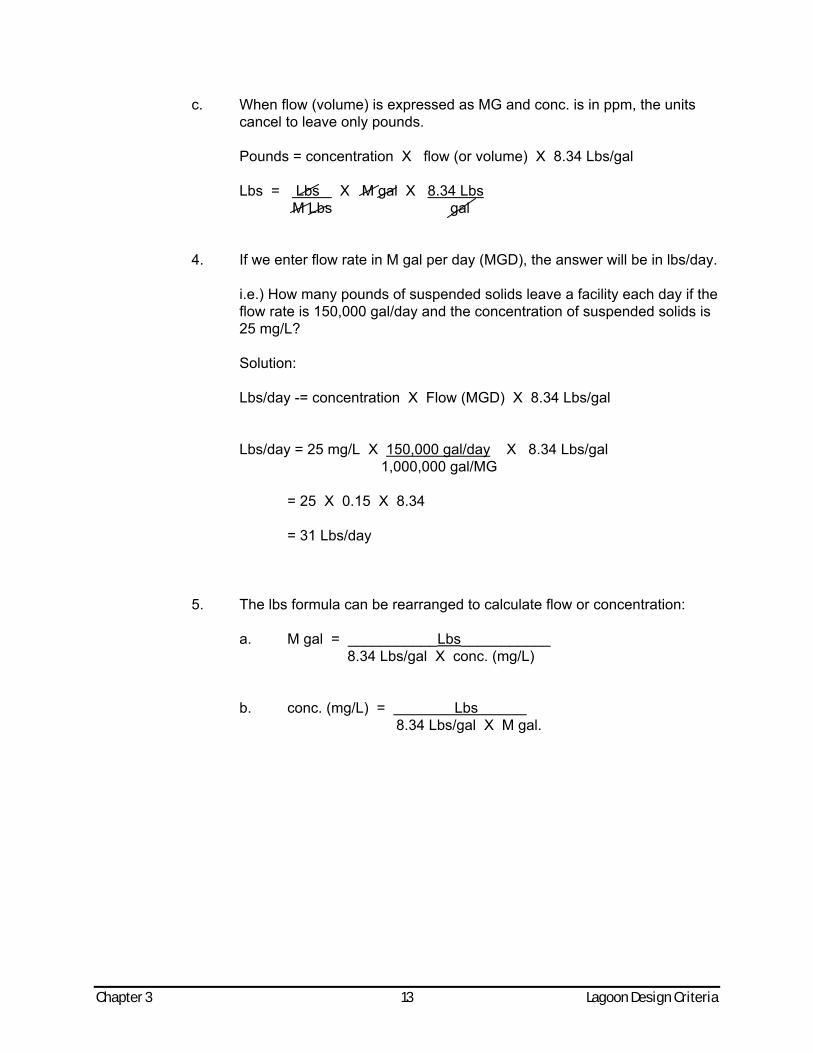
c. When flow (volume) is expressed as MG and conc. is in ppm, the units cancel to leave only pounds.
Pounds = concentration X flow (or volume) X 8.34 Lbs/gal Lbs = Lbs X M gal X 8.34 Lbs M Lbs gal
4. If we enter flow rate in M gal per day (MGD), the answer will be in lbs/day. i.e.) How many pounds of suspended solids leave a facility each day if the
flow rate is 150,000 gal/day and the concentration of suspended solids is 25 mg/L?
Solution: Lbs/day -= concentration X Flow (MGD) X 8.34 Lbs/gal Lbs/day = 25 mg/L X 150,000 gal/day X 8.34 Lbs/gal 1,000,000 gal/MG = 25 X 0.15 X 8.34 = 31 Lbs/day 5. The lbs formula can be rearranged to calculate flow or concentration: a. M gal = ___________Lbs___________ 8.34 Lbs/gal X conc. (mg/L) b. conc. (mg/L) = Lbs 8.34 Lbs/gal X M gal.
Chapter 3 13 Lagoon Design Criteria
Chapter 3 14 Lagoon Design Criteria
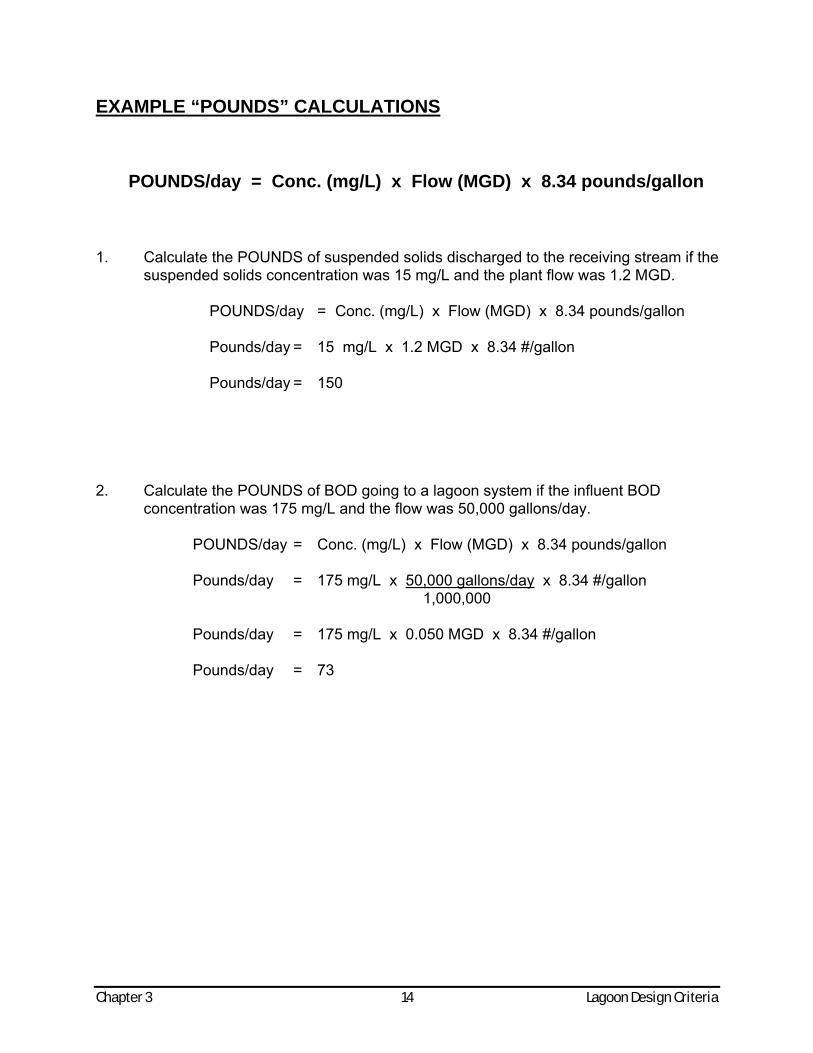
EXAMPLE “POUNDS” CALCULATIONS
POUNDS/day = Conc. (mg/L) x Flow (MGD) x 8.34 pounds/gallon
1. Calculate the POUNDS of suspended solids discharged to the receiving stream if the
suspended solids concentration was 15 mg/L and the plant flow was 1.2 MGD.
POUNDS/day = Conc. (mg/L) x Flow (MGD) x 8.34 pounds/gallon Pounds/day = 15 mg/L x 1.2 MGD x 8.34 #/gallon Pounds/day = 150
2. Calculate the POUNDS of BOD going to a lagoon system if the influent BOD
concentration was 175 mg/L and the flow was 50,000 gallons/day. POUNDS/day = Conc. (mg/L) x Flow (MGD) x 8.34 pounds/gallon Pounds/day = 175 mg/L x 50,000 gallons/day x 8.34 #/gallon 1,000,000 Pounds/day = 175 mg/L x 0.050 MGD x 8.34 #/gallon Pounds/day = 73
Chapter 3 15 Lagoon Design Criteria
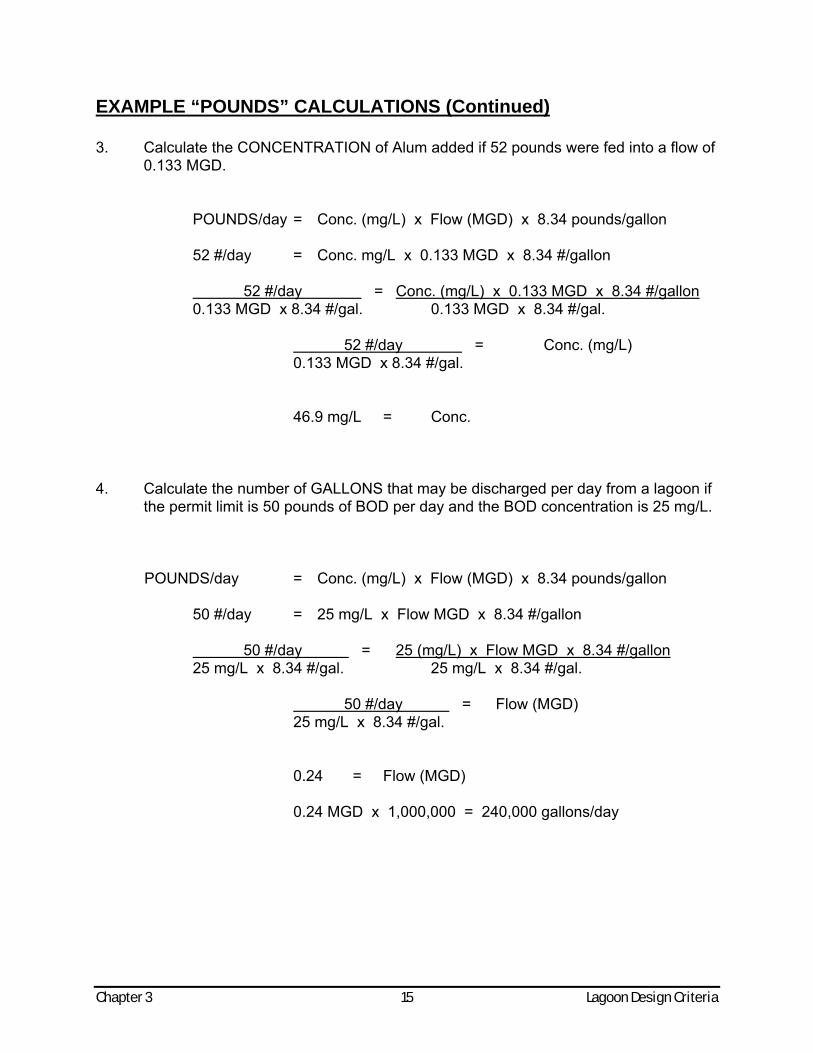
EXAMPLE “POUNDS” CALCULATIONS (Continued) 3. Calculate the CONCENTRATION of Alum added if 52 pounds were fed into a flow of
0.133 MGD. POUNDS/day = Conc. (mg/L) x Flow (MGD) x 8.34 pounds/gallon 52 #/day = Conc. mg/L x 0.133 MGD x 8.34 #/gallon 52 #/day = Conc. (mg/L) x 0.133 MGD x 8.34 #/gallon 0.133 MGD x 8.34 #/gal. 0.133 MGD x 8.34 #/gal. 52 #/day = Conc. (mg/L) 0.133 MGD x 8.34 #/gal. 46.9 mg/L = Conc.
4. Calculate the number of GALLONS that may be discharged per day from a lagoon if the permit limit is 50 pounds of BOD per day and the BOD concentration is 25 mg/L. POUNDS/day = Conc. (mg/L) x Flow (MGD) x 8.34 pounds/gallon 50 #/day = 25 mg/L x Flow MGD x 8.34 #/gallon 50 #/day = 25 (mg/L) x Flow MGD x 8.34 #/gallon 25 mg/L x 8.34 #/gal. 25 mg/L x 8.34 #/gal. 50 #/day = Flow (MGD) 25 mg/L x 8.34 #/gal. 0.24 = Flow (MGD) 0.24 MGD x 1,000,000 = 240,000 gallons/day
Chapter 3 16 Lagoon Design Criteria
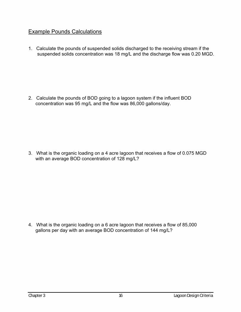
Example Pounds Calculations 1. Calculate the pounds of suspended solids discharged to the receiving stream if the
suspended solids concentration was 18 mg/L and the discharge flow was 0.20 MGD. 2. Calculate the pounds of BOD going to a lagoon system if the influent BOD
concentration was 95 mg/L and the flow was 86,000 gallons/day. 3. What is the organic loading on a 4 acre lagoon that receives a flow of 0.075 MGD
with an average BOD concentration of 128 mg/L? 4. What is the organic loading on a 6 acre lagoon that receives a flow of 85,000
gallons per day with an average BOD concentration of 144 mg/L?
Chapter 3 17 Lagoon Design Criteria
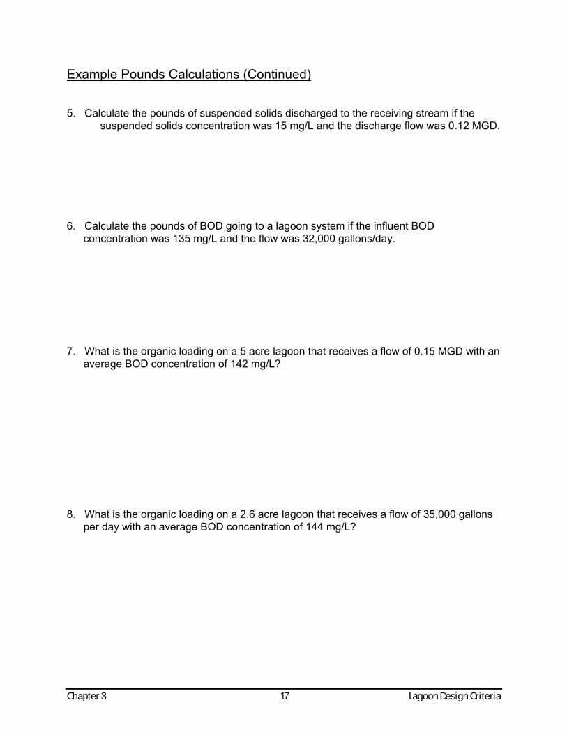
Example Pounds Calculations (Continued) 5. Calculate the pounds of suspended solids discharged to the receiving stream if the
suspended solids concentration was 15 mg/L and the discharge flow was 0.12 MGD. 6. Calculate the pounds of BOD going to a lagoon system if the influent BOD
concentration was 135 mg/L and the flow was 32,000 gallons/day. 7. What is the organic loading on a 5 acre lagoon that receives a flow of 0.15 MGD with an
average BOD concentration of 142 mg/L? 8. What is the organic loading on a 2.6 acre lagoon that receives a flow of 35,000 gallons
per day with an average BOD concentration of 144 mg/L?
Chapter 3 18 Lagoon Design Criteria
EXAMPLE PROBLEM FOR CALCULATING THE DISCHARGE VOLUME It is time for the fall discharge. Mr. Al G. La'Gune, the operator at Welldun, Michigan, has sampled the storage pond, had the necessary lab tests done, referred the results to the proper agency, and has received permission to discharge from the system to provide adequate storage for the winter. The following information has been gathered: A. Length of storage pond at median depth = 660 feet
B. Width of storage pond at median depth = 330 feet
C. Operating depth of storage pond = 7 feet
D. Depth of water now in storage pond = 6 feet
(over the minimum level)
E. Average daily influent flow = 42,000 GPD
F. Allowable discharge time = 20 days
G. Time to next discharge = 180 days
H. Desired "safety factor" = 15% (.15)
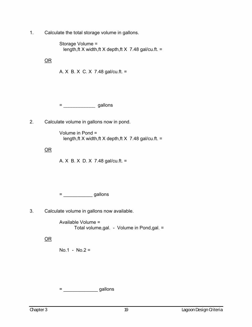
Chapter 3 19 Lagoon Design Criteria
1. Calculate the total storage volume in gallons. Storage Volume = length,ft X width,ft X depth,ft X 7.48 gal/cu.ft. = OR A. X B. X C. X 7.48 gal/cu.ft. = = ____________ gallons 2. Calculate volume in gallons now in pond. Volume in Pond = length,ft X width,ft X depth,ft X 7.48 gal/cu.ft. = OR A. X B. X D. X 7.48 gal/cu.ft. = = ___________ gallons 3. Calculate volume in gallons now available. Available Volume = Total volume,gal. - Volume in Pond,gal. = OR No.1 - No.2 = = _____________ gallons
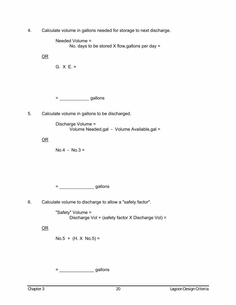
Chapter 3 20 Lagoon Design Criteria
4. Calculate volume in gallons needed for storage to next discharge. Needed Volume = No. days to be stored X flow,gallons per day = OR G. X E. = = ____________ gallons 5. Calculate volume in gallons to be discharged. Discharge Volume = Volume Needed,gal - Volume Available,gal = OR No.4 - No.3 = = ______________ gallons 6. Calculate volume to discharge to allow a "safety factor". "Safety" Volume = Discharge Vol + (safety factor X Discharge Vol) = OR No.5 + (H. X No.5) = = ______________ gallons
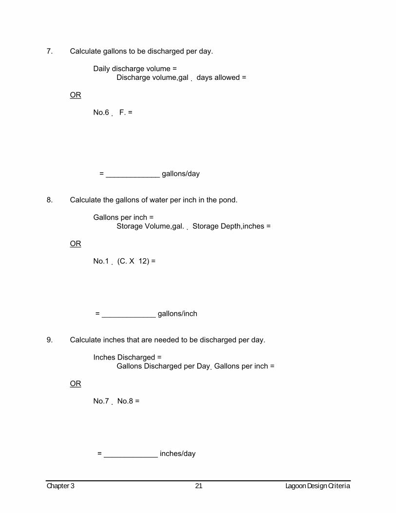
Chapter 3 21 Lagoon Design Criteria
7. Calculate gallons to be discharged per day. Daily discharge volume = Discharge volume,gal days allowed = OR No.6 F. = = _____________ gallons/day 8. Calculate the gallons of water per inch in the pond. Gallons per inch = Storage Volume,gal. Storage Depth,inches = OR No.1 (C. X 12) = = _____________ gallons/inch 9. Calculate inches that are needed to be discharged per day. Inches Discharged = Gallons Discharged per Day Gallons per inch = OR No.7 No.8 = = _____________ inches/day
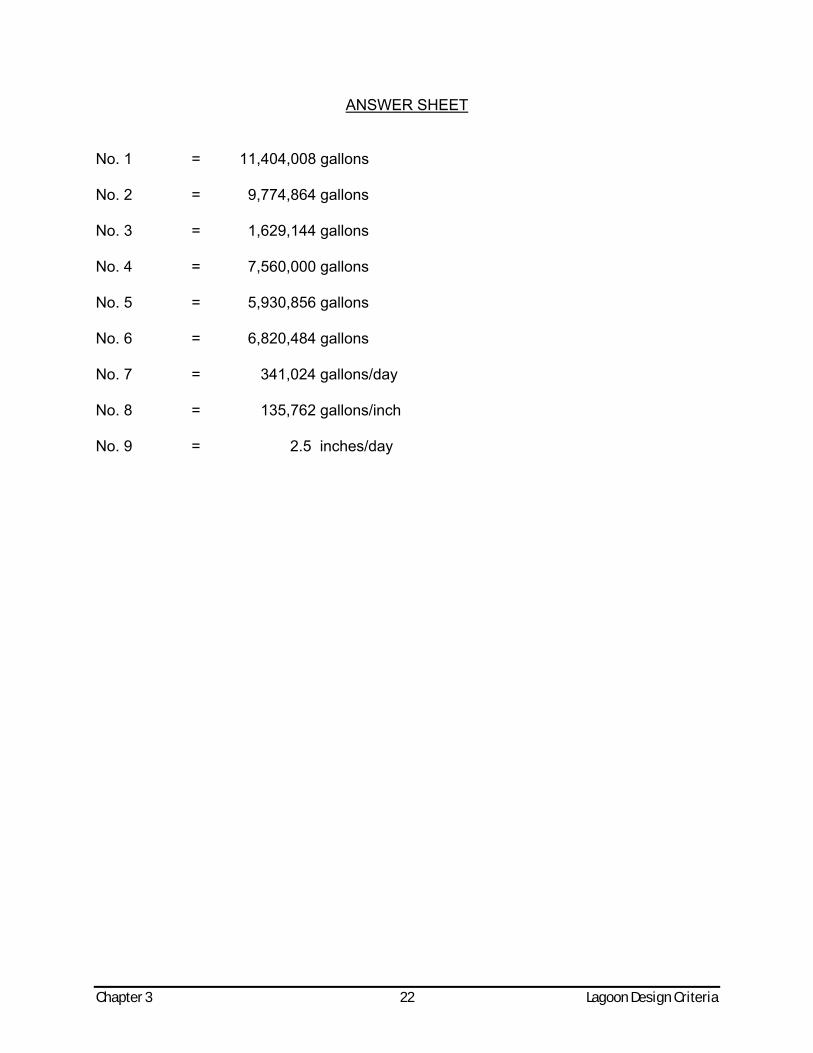
Chapter 3 22 Lagoon Design Criteria
ANSWER SHEET No. 1 = 11,404,008 gallons No. 2 = 9,774,864 gallons No. 3 = 1,629,144 gallons No. 4 = 7,560,000 gallons No. 5 = 5,930,856 gallons No. 6 = 6,820,484 gallons No. 7 = 341,024 gallons/day No. 8 = 135,762 gallons/inch No. 9 = 2.5 inches/day

4. Process Control
CHAPTER FOUR
PROCESS CONTROLS
GENERAL Waste stabilization lagoons are designed to have a holding capacity of approximately 180 days. This capacity provides the flexibility of controlling the discharge to once or twice each year, usually during spring runoff and late in the fall. OPERATION It has been widely advertised that waste stabilization lagoon systems are relatively operation and maintenance free. While this is true to some extent, there are certain operation and maintenance tasks that must be performed for effective lagoon operation. Certain features of each lagoon and the wastes to be treated are different for each installation. It is thus necessary to establish a specific management program with the district office of the Department of Natural Resources & Environment based on a joint judgement of the capabilities of this facility, the receiving stream and natural conditions which exist. There are however, some general principles with which the operator must be familiar. The operator should strive to develop the best possible quality of treated wastes under nuisance-free conditions for discharge at the appropriate time. Measures must be taken to control the entry of storm drainage, cooling water and other large volumes of water into the sewer system. Excess waters from these sources fill the lagoons to capacity, requiring premature discharges at inappropriate times. These excess volumes may severely reduce the time period available for stabilization of the wastes in the lagoons, thereby resulting in an unsatisfactory effluent quality. Lagoon treated wastes are not chemically disinfected (chlorinated) prior to discharge as are wastes treated in mechanical plants. The die-off of bacteria which occurs in nature over a long period is depended upon for reduction of these organisms. It is therefore essential that every gallon of waste be held as long as possible in an environment isolated from any recent raw waste addition to the system to assure the maximum reduction of bacteria which can be achieved in the absence of chemical disinfection. The principle of isolating wastes in the lagoons from raw waste additions for bacterial control can be achieved with either parallel or series operation. CELL MANAGEMENT - STARTUP In preparing to place a lagoon system in operation, the operator should first remove all grasses and other plants from the bottoms of the lagoons and from those portions of the side slopes which will be submerged by wastes. All valves and other portions of control structures should be operated to assure that they function properly. Where feasible, the first cell should be filled with clean water from a river or lake to a depth of about 2 feet before any raw wastes are added. This will provide an initial body of fresh water into which wastes may be discharged without odor nuisance which would surely result from exposure of the raw wastes directly to the atmosphere. In series feed systems, when the liquid depth in the first cell reaches 5 feet or more a portion can be transferred to a second cell usually from a point near the water surface filling it to a depth of 2 feet or more preferably within 2 or 3 days. This same procedure can be followed for initial feed to any subsequent cells.
CELL MANAGEMENT - ROUTINE The operator should continue to feed the raw waste as it is pumped from the sewer system into the cell first used, transferring an equivalent quantity to the second cell and in turn to any subsequent cells in series. Under normal conditions water depth should be maintained at about the same depth in all cells. In systems with cells of varying size, some adjustment may be necessary in the amount transferred from cell to cell. This is accomplished simply by leaving interconnecting valves between cells open in cases where the cells are all constructed at one elevation. With cells at different elevations regular adjustments of water level control gates will be necessary to maintain a fairly uniform depth in all cells. RETENTION - SEASONAL DISCHARGE The lagoon is built to provide retention of the wastewater to allow bacteria and algae to work as a stabilization team and to facilitate die-off of disease causing bacteria. Usually lagoons are located where the effluent must be discharged either directly or indirectly to waters with which people come into direct contact. These streams can best be protected for their established uses if no treated effluent is released into them during recreation seasons. For this reason most municipal stabilization lagoons in Michigan are designed to retain wastewaters for half of the year, with controlled releases during high stream flow periods in early spring and late fall. In this way the streams can be protected for beneficial uses most of the year, receiving stabilized effluents when there will be a minimum of undesirable impact upon the stream. PLANNING THE DISCHARGE The staff of the Department of Natural Resources & Environment assumes the responsibility for decision as to when and how much to discharge from the lagoon and for establishing the detailed discharge control program to be carried out by the operator. A department representative will determine the rate at which the lagoon should be discharged after considering the temperature and rate of flow in the receiving stream, the quality of the material to be discharged and any other limiting factors such as time remaining until the beginning of fishing season. In the spring the discharge should be so scheduled that it will be finished by the beginning of the fishing season. The fall discharge period should come at a time when fishing and recreational activity is at a minimum. Downstream users such as farmers pasturing dairy cattle should be notified of the planned period for discharging lagoon contents and suitable arrangements worked out. Impairment of lagoon effluent quality during discharge can be caused by high winds and by withdrawing too rapidly. Experiences have indicated that wave action caused by high winds have a tendency to re-suspend settled matter from lagoon sides and floor. One day the lagoon effluent may be relatively clear and possess low BOD and coliform concentrations and the next day it may be very turbid and much higher in BOD and coliforms. A high withdrawal rate from a lagoon may create high velocity currents near the discharge pipe scouring settled matter from the floor of the lagoon. Preferably the effluent should be taken from the top one foot of the water remaining in the lagoon. If the discharge line were laying on the bottom of the lagoon the effluent would usually contain bottom sediment material that has been scoured into the pipe. Lack of sunshine for a few days may cause the dissolved oxygen in the lagoon to fall below the predetermined satisfactory level. In such an event the discharge should be discontinued until the dissolved oxygen rises to this level.
Chapter 4 2 Process Control
SCHEDULE FOR DISPOSAL OF TREATED WASTES Effluent restrictions limit the period of discharge from raw waste stabilization lagoons to a brief period in early spring and late fall in order to minimize deleterious effects on stream water quality. The treated wastes are to be withdrawn in late fall to the minimum acceptable level of about 18 to 24 inches. At this time the natural flow in the streams is usually relatively high providing maximum dilution. Cool temperatures prevailing at this time of year result in relatively high dissolved oxygen concentration in the receiving streams. The high, summertime recreational use of the stream is over. These factors assure maximum capability of the stream to assimilate the treated waste and minimize adverse effects resulting from the discharge. In the spring within a few days after the ice cover has disappeared and oxygen has been restored in the lagoons, conditions are again favorable for discharge to the stream. Cool weather, high stream flow and little or no stream use will again assure a high level of assimilative capability in the stream and minimum opportunity for resultant injury. In a few instances, flow in the stream is so low in the fall of the year that it is necessary to retain the waste for once-a-year discharge in the spring season when stream flows are higher. Such a decision is made by the Department of Environmental Quality prior to construction of the system and specific instructions are provided the operator by the Department's staff. CELL MANAGEMENT - DISCHARGE TO STREAM In parallel feed systems, a lagoon cell should be completely isolated for a period of at least two weeks prior to discharging. In series feed systems, valving off the inflow to the last in a series of cells during the time it is being discharged may provide sufficient isolation to assure the best attainable quality of effluent. When this cell has been drained down to a depth of 18 to 20 inches, the outlet should be closed and treated waste transferred to the last cell from the next upstream cell. When this is accomplished the last cell should again be isolated for at least two weeks, following which it can be discharged. This operation can be repeated until the desired quantity has been discharged from all cells.
Chapter 4 3 Process Control

MULTI-CELLED PRIMARY - SERIES OPERATION
MULTI-CELLED PRIMARY - PARALLEL OPERATION
Chapter 4 4 Process Control

5. Sampling and Anlaysis
CHAPTER FIVE
SAMPLING AND LABORATORY ANALYSES
The Michigan Department of Natural Resources & Environment requires monthly operational reports on all wastewater facilities. The frequency of sampling and the kinds of analysis required depend upon whether the lagoon discharges annually, semiannually or continuously to the receiving waters. Groundwater discharges from spray, flood, or ridge and furrow irrigation systems, seepage lagoons, tile field subsurface or land underdrained all require groundwater monitoring through monitoring wells. The parameters are established on an individual basis. Raw wastewater entering a lagoon system may require sampling and testing to determine the organic load on the system. Stream samples for DO may, occasionally, be requested. SAMPLING PRINCIPLES Laboratory analysis would have very little value or significance if the material analyzed were not fairly representative of the condition or quality which actually prevailed. The greatest obstacle to the collection of a representative wastewater sample is the lack of homogeneity or uniform consistency, particularly of the raw waste as it arrives at the lagoons. Great care must be exercised to locate sampling points where there is good mixing of the material to be sampled, uninfluenced by previous deposits of sludge or scum or other effects. Any operator, however, who keeps uppermost in his mind the necessity for obtaining a well mixed, representative sample will find the best location within his system for its collection. Even under the most favorable circumstances, errors or inaccuracies in sampling are usually much greater than those made in laboratory analysis. The value of costly equipment and careful and skillful analysis work performed in the laboratory is negated when samples are carelessly obtained. Samples selected and handled carelessly can be of less value than no samples at all. The analysis results would only be confusing, misleading, and detrimental to any proper purpose or program. TYPES OF SAMPLES Grab samples are taken where a condition or quality remains relatively uniform for daily periods or longer. They are also used where the sample requires immediate analysis by reason of a high degree of instability of the constituent to be analyzed, such as lagoon dissolved oxygen. Grab samples are also collected for bacteriological analysis. Composite or integrated samples should be taken for all laboratory analyses where it is desired to obtain a measure of the average quality or conditions which prevail for periods of a day or longer. Such samples would include those obtained for routine analysis of solids, 5-day BOD, nitrogen series and phosphates, in either the raw waste influent to the lagoon or effluent from the lagoon during the discharge period. Generally, a 2-liter (slightly more than two quarts) sample is sufficient for most physical and chemical analyses. However, it should be noted that fecal coliform samples must be collected in separate sterilized bottles. Sampling Locations Samples of the raw wastewater (influent) may be obtained in either the wet well of the lift station (which pumps the wastewater to the cells), or the inlet manhole of the control structure at the lagoon site. Do not take the influent sample from the wet well basin as solids tend to settle out immediately upon entering the wet well. A bucket on a rope is one
method which may be used to collect this sample as the wastewater enters the wet well or structure. Effluent samples should be obtained from the outlet control structure after the discharge and draw down procedure has been initiated. SAMPLING AND ANALYSIS DURING DISCHARGE Communities operating lagoons in Michigan are expected to carry out the following sampling and analysis program during semi-annual discharge periods.
IN NO CIRCUMSTANCE SHOULD A DISCHARGE BE MADE UNLESS SPECIFICALLY AUTHORIZED BY THE MICHIGAN
DEPARTMENT OF NATURAL RESOURCES & ENVIRONMENT.
1. Sampling Within Lagoon - Near Outlet (Dissolved Oxygen) - Samples should be
collected near the discharge pipe at least 3 times daily for dissolved oxygen analysis. The operator should perform a dissolved oxygen test on the grab sample collected immediately after sample collection.
2. Sampling of Raw Wastes - Routine raw waste sampling is not required at this time, but arrangements may be made by the Department of Natural Resources & Environment (district office) at some time during the year for a survey to determine the quantity and quality of raw waste received.
3. Sampling - Lagoon Effluent - Composite samples of the lagoon effluent should be collected (at points designated by the Department of Environmental Quality) for tests for suspended solids, 5-day BOD, pH, and phosphorus. Composite samples are to be collected 5 days per week, or as directed by the Department, during the period of discharge. Each composite sample is to be composed of at least 3 equal volume portions; one collected in the morning, one about noon, and another in the late afternoon. A wide mouth glass one gallon jug is satisfactory for this purpose. These samples must be refrigerated during sampling and until delivered to the laboratory for analysis (cooled to 4°C) within a 2 day holding period.
4. Analysis of Lagoon Effluent - Arrangements should be made with a nearby community having a wastewater treatment plant laboratory to perform analyses on all samples of the lagoon effluent for 5-day BOD, suspended solids, volatile suspended solids, pH, phosphorus, and fecal coliforms.
At least one grab sample per day, 5 days per week, is to be collected for analysis of fecal coliforms. A special sterilized bottle should be used for this purpose. A supply of these bottles will be made available by the wastewater treatment facility laboratory or the Department prior to each discharge season. If unable to contract with a treatment plant laboratory, please call the MDNRE district office for possible assistance. These samples must be cooled to ≤ 6°C and a 6 hour holding period. Stream Samples The stream samples which are to be used for dissolved oxygen determinations should be collected as near as possible to the center of the flow to be representative of the stream and to avoid disturbing the stream bed. The upstream sample should be collected somewhere above the outfall structure of the lagoon. The downstream sample should be
Chapter 5 2 Sampling and Analysis
collected a reasonable distance downstream from the outfall structure, giving the effluent adequate time to mix thoroughly into the stream. Equipment When collecting the 24-hour composite sample of the raw wastewater, one of the
following methods may be used: a. By using an automatic sampling device and compositing according to the flow at the
time of sampling. Automatic samplers may be available through the MDNRE on a loan basis, as well as assistance in setting up a sampling survey on
the raw wastewater. These arrangements are made by the district office when deemed necessary.
b. By taking individual samples manually and then compositing according to the flow at the time of sampling.
In each of these procedures, be sure that the wastewater collected is thoroughly mixed to assure that a representative sample is used for analysis.
WHEN SAMPLING FOR COLIFORM THE SAME SAMPLER SHOULD NEVER BE USED IF BOTH THE RAW INFLUENT AND THE EFFLUENT SAMPLES ARE TO BE COLLECTED. CONTAMINATION FROM FECAL COLIFORMS WILL RESULT EVEN IF THE SAMPLER IS WASHED BEFORE COLLECTING THE POND EFFLUENT SAMPLE.
Sampling for dissolved oxygen (D.O.) requires a special procedure and apparatus to prevent the dissolved oxygen content of the sample to change because of contact with the air. Further discussion on D.O. will be presented later in this section. Chlorine Residual Sampling And Test In some cases, disinfection may be required on the effluent from stabilization ponds in order to meet the fecal coliform standards. Disinfection is a means of destroying the organisms which are capable of producing disease. Ozone, ultra-violet light and chlorine are used as disinfectants; however, chlorine is the most widely used agent to destroy fecal coliform organisms, mainly because of cost and accessibility factors. If you are required to chlorinate your pond effluent to meet the effluent standards you must run a residual chlorine test on the effluent to determine if adequate chlorine is used. This sample should consist of a grab sample. However, the analysis should be performed immediately after it is collected. This analysis may be done by either the colorimetric (iodometric method) or the amperometric titration method. The test for residual chlorine measures the total excess chlorine remaining after a specified contact period. The general "rule of thumb" is to have a 0.5 mg/L residual after a contact period of 15 minutes. However, the amount of residual required after 15 minutes should be substantiated on the basis of the test for fecal coliforms and compliance with the effluent standards. For control purposes only, the DPD method for total chlorine residual has replaced the orthotolidine-arsenite (OTA) method.
Chapter 5 3 Sampling and Analysis
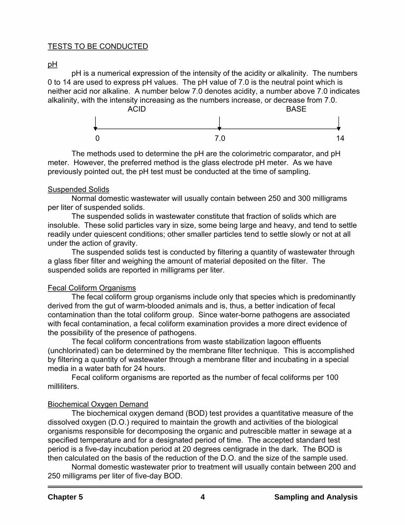
TESTS TO BE CONDUCTED pH pH is a numerical expression of the intensity of the acidity or alkalinity. The numbers 0 to 14 are used to express pH values. The pH value of 7.0 is the neutral point which is neither acid nor alkaline. A number below 7.0 denotes acidity, a number above 7.0 indicates alkalinity, with the intensity increasing as the numbers increase, or decrease from 7.0. ACID BASE 0 7.0 14
The methods used to determine the pH are the colorimetric comparator, and pH meter. However, the preferred method is the glass electrode pH meter. As we have previously pointed out, the pH test must be conducted at the time of sampling. Suspended Solids Normal domestic wastewater will usually contain between 250 and 300 milligrams per liter of suspended solids. The suspended solids in wastewater constitute that fraction of solids which are insoluble. These solid particles vary in size, some being large and heavy, and tend to settle readily under quiescent conditions; other smaller particles tend to settle slowly or not at all under the action of gravity. The suspended solids test is conducted by filtering a quantity of wastewater through a glass fiber filter and weighing the amount of material deposited on the filter. The suspended solids are reported in milligrams per liter. Fecal Coliform Organisms The fecal coliform group organisms include only that species which is predominantly derived from the gut of warm-blooded animals and is, thus, a better indication of fecal contamination than the total coliform group. Since water-borne pathogens are associated with fecal contamination, a fecal coliform examination provides a more direct evidence of the possibility of the presence of pathogens. The fecal coliform concentrations from waste stabilization lagoon effluents (unchlorinated) can be determined by the membrane filter technique. This is accomplished by filtering a quantity of wastewater through a membrane filter and incubating in a special media in a water bath for 24 hours. Fecal coliform organisms are reported as the number of fecal coliforms per 100 milliliters. Biochemical Oxygen Demand The biochemical oxygen demand (BOD) test provides a quantitative measure of the dissolved oxygen (D.O.) required to maintain the growth and activities of the biological organisms responsible for decomposing the organic and putrescible matter in sewage at a specified temperature and for a designated period of time. The accepted standard test period is a five-day incubation period at 20 degrees centigrade in the dark. The BOD is then calculated on the basis of the reduction of the D.O. and the size of the sample used. Normal domestic wastewater prior to treatment will usually contain between 200 and 250 milligrams per liter of five-day BOD.
Chapter 5 4 Sampling and Analysis
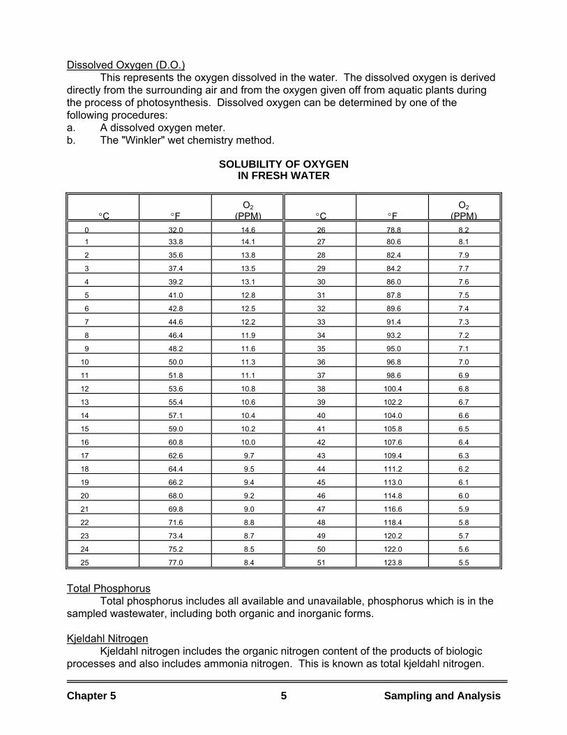
Chapter 5 5 Sampling and Analysis
Dissolved Oxygen (D.O.) This represents the oxygen dissolved in the water. The dissolved oxygen is derived directly from the surrounding air and from the oxygen given off from aquatic plants during the process of photosynthesis. Dissolved oxygen can be determined by one of the following procedures: a. A dissolved oxygen meter. b. The "Winkler" wet chemistry method.
SOLUBILITY OF OXYGEN IN FRESH WATER
°C
°F
O2 (PPM)
°C
°F
O2 (PPM)
0 32.0 14.6 26 78.8 8.2 1 33.8 14.1 27 80.6 8.1
2 35.6 13.8 28 82.4 7.9
3 37.4 13.5 29 84.2 7.7
4 39.2 13.1 30 86.0 7.6
5 41.0 12.8 31 87.8 7.5
6 42.8 12.5 32 89.6 7.4
7 44.6 12.2 33 91.4 7.3
8 46.4 11.9 34 93.2 7.2
9 48.2 11.6 35 95.0 7.1
10 50.0 11.3 36 96.8 7.0
11 51.8 11.1 37 98.6 6.9
12 53.6 10.8 38 100.4 6.8
13 55.4 10.6 39 102.2 6.7
14 57.1 10.4 40 104.0 6.6
15 59.0 10.2 41 105.8 6.5
16 60.8 10.0 42 107.6 6.4
17 62.6 9.7 43 109.4 6.3
18 64.4 9.5 44 111.2 6.2
19 66.2 9.4 45 113.0 6.1
20 68.0 9.2 46 114.8 6.0
21 69.8 9.0 47 116.6 5.9
22 71.6 8.8 48 118.4 5.8
23 73.4 8.7 49 120.2 5.7
24 75.2 8.5 50 122.0 5.6
25 77.0 8.4 51 123.8 5.5
Total Phosphorus Total phosphorus includes all available and unavailable, phosphorus which is in the sampled wastewater, including both organic and inorganic forms. Kjeldahl Nitrogen Kjeldahl nitrogen includes the organic nitrogen content of the products of biologic processes and also includes ammonia nitrogen. This is known as total kjeldahl nitrogen.
Chapter 5 6 Sampling and Analysis
FREQUENCY OF TESTS The equipment required to perform the required analytical tests is usually not provided with the construction of stabilization lagoons because it would be quite costly to provide an extensive laboratory facility. In some cases, the community may have laboratory facilities in which the analyses could be performed if the equipment necessary for these tests was purchased. A private testing firm may be retained or arrangements with a neighboring community which has laboratory facilities may be made for conducting these required tests. However, the operator should be responsible for the collection of the samples and should conduct the pH, DO, and chlorine residual tests, and these tests must be performed at the time they are collected. Sewage samples deteriorate rapidly if subjected to summer temperatures. Exclusion of sunlight is recommended. Collected samples should be transferred to a refrigerator where they can be stored until removed for analysis. A temperature of 40�F (4�C) will prevent deterioration for approximately 24 hours. Containers used in collecting and storage of samples must be kept clean. GROUNDWATER MONITORING GUIDELINES FOR ON LAND WASTE DISPOSAL FACILITIES Monitoring Objectives The function of a groundwater monitoring program for proposed on land waste disposal facilities is to confirm judgements made during facility design. This is to be accomplished by a continuing, long-term, in-depth hydrogeologic study regarding the performance of the system and its influence on surrounding groundwater conditions. This applies to: 1. Wastewater treatment lagoons. 2. Wastewater storage lagoons. 3. Land irrigation systems. 4. Large subsurface disposal fields. 5. Wastewater sludge disposal sites. 6. Sanitary landfills. 7. Industrial waste concentrates disposal sites. At all such existing sites groundwater monitoring programs are needed to determine the influence of disposal practices on the groundwater resource.
Chapter 5 7 Sampling and Analysis
Design of Monitoring Wells Monitoring wells must be designed and located to meet the specific geologic and hydrologic conditions at each site. Consideration must be given to the following: 1. Geological soil and rock formations existing at the specific site. 2. Depth to and thickness of an impervious layer. 3. Direction of flow of groundwater and anticipated rate of movement. 4. Depth to seasonal high water table and an indication of seasonal variations in
groundwater depth and direction of movement. 5. Nature, extent, and consequences of mounding of groundwater which can be
anticipated to occur above the naturally occurring water table. 6. Location of nearby streams and swamps. 7. Potable and non-potable water supply wells. 8. Other data as appropriate to the specific system design. Groundwater quality should be monitored immediately below the water table surface near the application site as pollutional materials entering the groundwater system may have a tendency to remain in the upper few feet. Applied wastewater or leachate will generally be depressed within the groundwater system as the material travels away from the site. The need for sampling at more than one depth within a groundwater system will depend upon geologic conditions and distance from the pollutional source. Definition of the flow system with depth will be necessary to properly determine the depth to be monitored, especially when mounding is superimposed in the existing groundwater system. Additional design and construction considerations are: 1. Monitoring wells in fine textured soils will require special construction such as
gravel packing around the screen. 2. Wells constructed to a depth of 20' or more should be 4" in diameter to
facilitate use of submersible pump equipment for sample collection unless alternative sampling methods are approved by the reviewing agency.
3. Construction should be by a registered well driller or contractor covered under Act 315, P.A. of 1969 using approved modern construction methods.
4. Casings shall be grouted and capped and a cap locking device provided. Use of a vented cap is desirable but care must be taken to prevent introduction of contaminants through such vents.
5. The well casing should be protected against accidental damage and adequately marked to be clearly visible during winter and summer conditions.
6. Each well should be labeled and identified (owner, owners address, well number, use of well and warning).
7. If a monitoring well is to be permanently abandoned, approved procedures are to be followed. Contact your district office.
Location Groundwater monitoring wells must be located so as to detect any influence of wastewater, solid waste, or sludge application on the groundwater resource. A minimum of one groundwater monitoring well must be provided in each direction of groundwater movement near the pollutional source with adequate consideration being given to possible changes in groundwater flow due to mounding effects. The orientation and spacing of multiple wells shall be determined by conditions at each site.
Chapter 5 8 Sampling and Analysis
Water Level Measurement The following considerations apply with regard to water level measurement: 1. Water levels should be determined by methods giving precision to 1/8 inch or
0.01 foot. (Example - wetted tape method). 2. Measurements should be made from the top of the casing with the elevation
of all casings in the monitoring wells system related to a permanent reference point, using USGS datum.
3. Water level measurements are to be made under static conditions prior to pumping for sample collection.
4. Monitoring wells should be installed early in the site development or construction sequence and monthly water level readings obtained during the construction period and during the first two years of system operation to provide background information. Subsequent water level measurement frequency should be in accordance with a schedule established on a case by case basis.
5. All wells should be securely capped and locked when not in use. Water Sampling Background Water Quality: A minimum of three monthly samples should be collected from each monitoring well prior to placing the facility in operation. In cases where background water quality adjacent to the site may be influenced by prior waste applications, provision of monitoring wells or analysis of water quality from existing wells in the same aquifer beyond the area of influence will be necessary. Operating Schedule: Samples should be collected monthly during the first two years of operation (unless a less frequent sampling schedule is approved by the reviewing agency). After the accumulation of a minimum of two years of groundwater monitoring information, modification of the frequency of sampling may be considered upon written request. Sample Collection 1. A measured amount of water equal to or greater than three times the amount
of water in the well and/or gravel pack should be exhausted from the well before taking a sample for analysis. In the case of very low permeability soils the well may have to be exhausted and allowed to refill before a sample is collected.
2. Pumping equipment shall be thoroughly rinsed before use in each monitoring well.
3. A pressure tank shall not be used with a sampling system since the water in the pressure tank would be particularly difficult to exhaust.
4. Water pumped from each monitoring well should be discharged to the ground surface away from the wells to avoid recycling of flow in high permeability soil areas or soil erosion.
5. Samples must be collected, stored, and transported to the laboratory in a manner so as to avoid contamination or interference with subsequent analyses.
Chapter 5 9 Sampling and Analysis
Sample Analysis Water samples collected for background water quality should be analyzed for the following: (Note: Parameters for groundwater monitoring at industrial waste disposal sites must be established on an individual basis depending on the composition of the wastes applied). Wastewater Sites Sanitary Landfills 1. Chloride 1. Chloride 2. Specific Conductance 2. Iron 3. pH 3. Specific Conductance 4. Total Hardness 4. pH 5. Alkalinity 5. Total Hardness 6. (a) Ammonia Nitrogen 6. Alkalinity (b) Nitrate Nitrogen 7. Sulfate (c) Nitrite Nitrogen 8. Chemical Oxygen Demand 7. Total Phosphorus 9. Any heavy metals or toxic 8. Methylene Blue Active Substances substances found in the 9. Chemical Oxygen Demand applied waste. 10. Any heavy metals or toxic substances found in the applied waste.
After adequate background water quality information has been obtained, a minimum of one sample per year, (obtained at the end of the irrigation season in the case of seasonal wastewater operations) should be collected from each well and analyzed for the above constituents. All other water samples collected in accordance with the operating schedule should be analyzed for chlorides and specific conductance at wastewater facilities or chloride, iron and C.O.D. at sanitary landfills as indicators of changes in groundwater quality resulting from the wastes applied. If significant changes are noted in the indicator parameters, samples should immediately be analyzed for the other parameters listed above to determine the extent of water quality deviation from background levels. Groundwater Monitoring System Reports Well Location Plan: The owner of the system is to provide a plan, drawn to scale, showing the location of each monitoring well and its relationship to the wastewater treatment lagoons, storage lagoon, irrigation area, sludge disposal site, sanitary landfill or subsurface disposal field and to other significant features such as municipal or private wells, surface streams, etc. It is suggested that individualized well location plan maps be prepared by the project consultant. The plan map shall include casing elevation information to facilitate conversion of water level measurements to datum elevations. Reports: The owner of the system is to file standard reports of observations and sample analyses, obtained in accordance with the schedule listed above, with the responsible state agency within 30 days of sample collection. Notification of significant deviations from background quality is to be given immediately.


6. Maintenance Practices
CHAPTER SIX MAINTENANCE PRACTICES GENERAL Although waste stabilization lagoons require a minimum amount of maintenance, they cannot be expected to provide adequate treatment without proper attention. If lagoons are neglected, they can deteriorate to the point where very costly repairs and possible reconstruction are required. Generally, maintenance activities are divided into two categories: corrective maintenance and preventive maintenance. Corrective maintenance, sometimes called "repair", is activity conducted to get equipment working again. Examples of this type of maintenance are replacing motor or pump bearings that have siezed up, replacing broken drive belts, reparing inoperable valves, and repairing erosion damage to pond dikes.
Preventive maintenance is a schedule of planned maintenance actions aimed at the prevention of breakdowns and failures. The primary goal of preventive maintenance is to prevent the failure of equipment before it actually occurs. Preventive maintenance activities include equipment checks, partial or complete overhauls at specified periods, oil changes, lubrication and so on. It is not the purpose of this course to provide details of maintenance programs for lagoon systems. However, operators are strongly urged develop a maintenance program that includes sections on preventive maintenance schedules, spare part inventories, equipment supplier lists and contacts, equipment manuals, etc. This may sound like an impossible task considering all the duties that a lagoon operator is typically responsible for, but, if a program is developed one section at a time and made facility specific, the job can be completed in a relatively short time and will prove to be an invaluable tool. Even though it may take time to research, obtain training, and to develop a maintenance program, experience has shown that many work hours, much aggravation, and even permit violations have been reduced or eliminated when a good maintenance program, specific to the particular facility, has been implemented, followed, and regularly up-dated. Although we are not going to discuss the details of a maintenance program in this course, there are some aspects of maintenance that are specific to lagoon operations that should be emphasized. EQUIPMENT MAINTENANCE Fence, Sign, and Access Road Maintenance The possibility of contamination demands that livestock be excluded from the pond area. Fences should be inspected periodically and kept in good repair and gates should be closed and padlocked every time the system is unattended. Since children
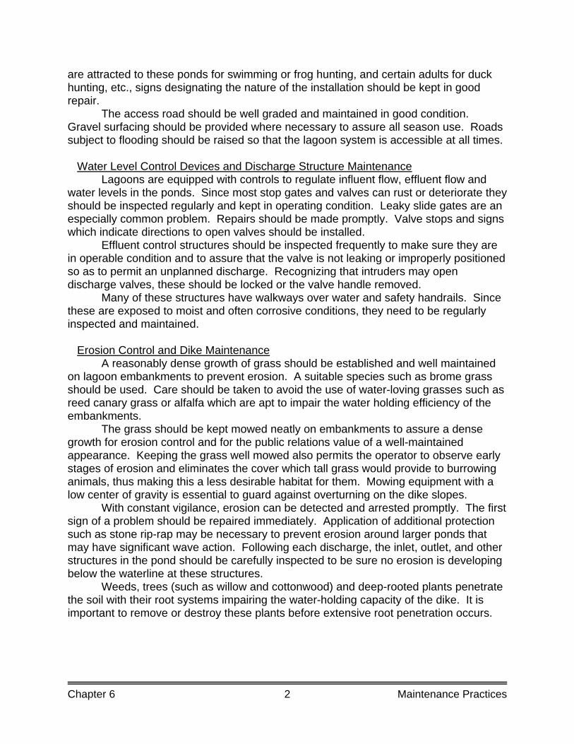
Chapter 6 2 Maintenance Practices
are attracted to these ponds for swimming or frog hunting, and certain adults for duck hunting, etc., signs designating the nature of the installation should be kept in good repair. The access road should be well graded and maintained in good condition. Gravel surfacing should be provided where necessary to assure all season use. Roads subject to flooding should be raised so that the lagoon system is accessible at all times. Water Level Control Devices and Discharge Structure Maintenance Lagoons are equipped with controls to regulate influent flow, effluent flow and water levels in the ponds. Since most stop gates and valves can rust or deteriorate they should be inspected regularly and kept in operating condition. Leaky slide gates are an especially common problem. Repairs should be made promptly. Valve stops and signs which indicate directions to open valves should be installed. Effluent control structures should be inspected frequently to make sure they are in operable condition and to assure that the valve is not leaking or improperly positioned so as to permit an unplanned discharge. Recognizing that intruders may open discharge valves, these should be locked or the valve handle removed. Many of these structures have walkways over water and safety handrails. Since these are exposed to moist and often corrosive conditions, they need to be regularly inspected and maintained. Erosion Control and Dike Maintenance A reasonably dense growth of grass should be established and well maintained on lagoon embankments to prevent erosion. A suitable species such as brome grass should be used. Care should be taken to avoid the use of water-loving grasses such as reed canary grass or alfalfa which are apt to impair the water holding efficiency of the embankments. The grass should be kept mowed neatly on embankments to assure a dense growth for erosion control and for the public relations value of a well-maintained appearance. Keeping the grass well mowed also permits the operator to observe early stages of erosion and eliminates the cover which tall grass would provide to burrowing animals, thus making this a less desirable habitat for them. Mowing equipment with a low center of gravity is essential to guard against overturning on the dike slopes. With constant vigilance, erosion can be detected and arrested promptly. The first sign of a problem should be repaired immediately. Application of additional protection such as stone rip-rap may be necessary to prevent erosion around larger ponds that may have significant wave action. Following each discharge, the inlet, outlet, and other structures in the pond should be carefully inspected to be sure no erosion is developing below the waterline at these structures. Weeds, trees (such as willow and cottonwood) and deep-rooted plants penetrate the soil with their root systems impairing the water-holding capacity of the dike. It is important to remove or destroy these plants before extensive root penetration occurs.
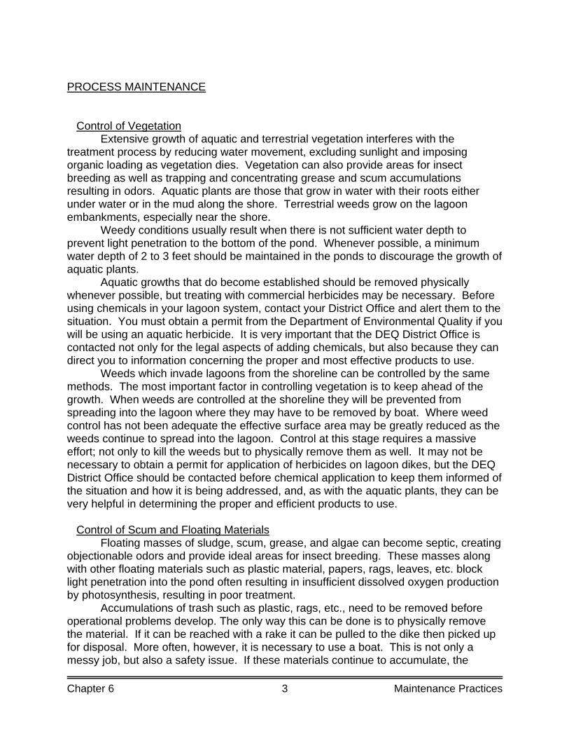
Chapter 6 3 Maintenance Practices
PROCESS MAINTENANCE Control of Vegetation Extensive growth of aquatic and terrestrial vegetation interferes with the treatment process by reducing water movement, excluding sunlight and imposing organic loading as vegetation dies. Vegetation can also provide areas for insect breeding as well as trapping and concentrating grease and scum accumulations resulting in odors. Aquatic plants are those that grow in water with their roots either under water or in the mud along the shore. Terrestrial weeds grow on the lagoon embankments, especially near the shore. Weedy conditions usually result when there is not sufficient water depth to prevent light penetration to the bottom of the pond. Whenever possible, a minimum water depth of 2 to 3 feet should be maintained in the ponds to discourage the growth of aquatic plants. Aquatic growths that do become established should be removed physically whenever possible, but treating with commercial herbicides may be necessary. Before using chemicals in your lagoon system, contact your District Office and alert them to the situation. You must obtain a permit from the Department of Environmental Quality if you will be using an aquatic herbicide. It is very important that the DEQ District Office is contacted not only for the legal aspects of adding chemicals, but also because they can direct you to information concerning the proper and most effective products to use. Weeds which invade lagoons from the shoreline can be controlled by the same methods. The most important factor in controlling vegetation is to keep ahead of the growth. When weeds are controlled at the shoreline they will be prevented from spreading into the lagoon where they may have to be removed by boat. Where weed control has not been adequate the effective surface area may be greatly reduced as the weeds continue to spread into the lagoon. Control at this stage requires a massive effort; not only to kill the weeds but to physically remove them as well. It may not be necessary to obtain a permit for application of herbicides on lagoon dikes, but the DEQ District Office should be contacted before chemical application to keep them informed of the situation and how it is being addressed, and, as with the aquatic plants, they can be very helpful in determining the proper and efficient products to use. Control of Scum and Floating Materials Floating masses of sludge, scum, grease, and algae can become septic, creating objectionable odors and provide ideal areas for insect breeding. These masses along with other floating materials such as plastic material, papers, rags, leaves, etc. block light penetration into the pond often resulting in insufficient dissolved oxygen production by photosynthesis, resulting in poor treatment. Accumulations of trash such as plastic, rags, etc., need to be removed before operational problems develop. The only way this can be done is to physically remove the material. If it can be reached with a rake it can be pulled to the dike then picked up for disposal. More often, however, it is necessary to use a boat. This is not only a messy job, but also a safety issue. If these materials continue to accumulate, the
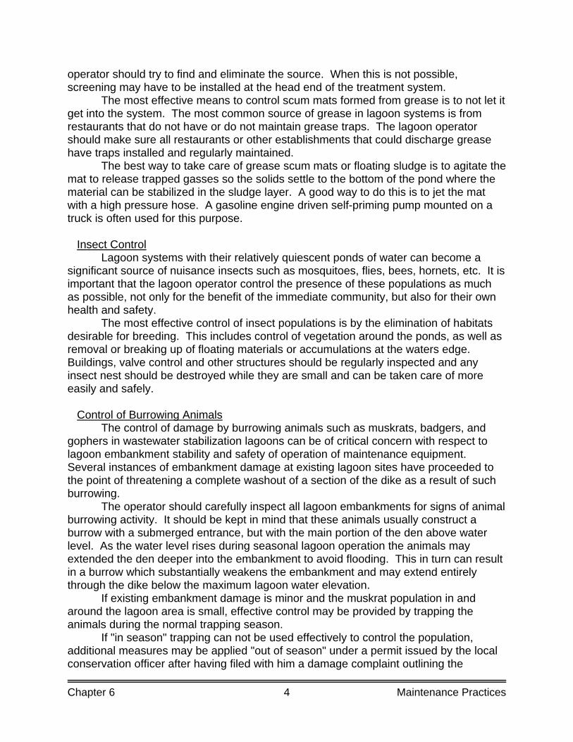
Chapter 6 4 Maintenance Practices
operator should try to find and eliminate the source. When this is not possible, screening may have to be installed at the head end of the treatment system. The most effective means to control scum mats formed from grease is to not let it get into the system. The most common source of grease in lagoon systems is from restaurants that do not have or do not maintain grease traps. The lagoon operator should make sure all restaurants or other establishments that could discharge grease have traps installed and regularly maintained. The best way to take care of grease scum mats or floating sludge is to agitate the mat to release trapped gasses so the solids settle to the bottom of the pond where the material can be stabilized in the sludge layer. A good way to do this is to jet the mat with a high pressure hose. A gasoline engine driven self-priming pump mounted on a truck is often used for this purpose. Insect Control Lagoon systems with their relatively quiescent ponds of water can become a significant source of nuisance insects such as mosquitoes, flies, bees, hornets, etc. It is important that the lagoon operator control the presence of these populations as much as possible, not only for the benefit of the immediate community, but also for their own health and safety. The most effective control of insect populations is by the elimination of habitats desirable for breeding. This includes control of vegetation around the ponds, as well as removal or breaking up of floating materials or accumulations at the waters edge. Buildings, valve control and other structures should be regularly inspected and any insect nest should be destroyed while they are small and can be taken care of more easily and safely. Control of Burrowing Animals The control of damage by burrowing animals such as muskrats, badgers, and gophers in wastewater stabilization lagoons can be of critical concern with respect to lagoon embankment stability and safety of operation of maintenance equipment. Several instances of embankment damage at existing lagoon sites have proceeded to the point of threatening a complete washout of a section of the dike as a result of such burrowing. The operator should carefully inspect all lagoon embankments for signs of animal burrowing activity. It should be kept in mind that these animals usually construct a burrow with a submerged entrance, but with the main portion of the den above water level. As the water level rises during seasonal lagoon operation the animals may extended the den deeper into the embankment to avoid flooding. This in turn can result in a burrow which substantially weakens the embankment and may extend entirely through the dike below the maximum lagoon water elevation. If existing embankment damage is minor and the muskrat population in and around the lagoon area is small, effective control may be provided by trapping the animals during the normal trapping season. If "in season" trapping can not be used effectively to control the population, additional measures may be applied "out of season" under a permit issued by the local conservation officer after having filed with him a damage complaint outlining the
Chapter 6 5 Maintenance Practices
problem of embankment damage which exists. Control measures which may then be applied include year-round trapping and shooting of the animals, or, in cases of damage when other methods of control are ineffective, use of chemical rodenticide under the supervision of personnel from the Department of Environmental Quality. To be most effective, control measures should be continued through late spring after the burrowing animals have completed their seasonal migration from winter homes in marshes and low areas to summer feeding areas. Because of their migratory habits, repeating the control program on an annual basis may be necessary. Efforts should be made at all times to repair damage to the lagoon embankments as soon as it is observed. It is noted that muskrats use vegetation for food and nest construction and are reluctant to nest where an abundant supply of these materials is not available; another very good reason to keep weeds and vegetation under control. Odor Control As a general rule, lagoon systems should be free of objectionable odors. There may be some odors coming from primary pond(s) in the spring of the year just after ice cover melts as the pond recovers from anaerobic conditions during the winter. If this occurs, it should only last for a very few days. When spring time odors occur for an extended time or odors are present at other times of the year, steps must be take to determine and address the source of the problem. Occasionally, odors result when the sludge layer in the pond approaches the typical design limit of two feet. Lagoon system operators should use a “sludge judge” or similar device to monitor the depth of the sludge level often enough to head off any decrease in treatment efficiency or the development of odor problems. Since the sludge depth increases slowly over a number of years, it is only necessary to measure the level every 3 to 4 years for newer systems and then every 1 to 2 years as levels increase to over about one foot. It is important to monitor the sludge depth often enough to allow time for planning and getting permits to remove sludge from the lagoon, as this may take many months. Most odor problems in lagoon systems are the result of anaerobic conditions caused by high organic loading to the treatment system due to increased growth of the community, expansion of industrial production, or shock organic loadings from an industry. If regular monitoring of plant loading is done as discussed in the chapter on Process Control, preparations can be made to add aeration or expand the system well before design limits are reached and therefore prevent odor problems. Also, effective control requires constant vigilance by the lagoon operator to monitor the discharges from industries having organic wastes, such as milk or food processors, and working with the management of these facilities to ensure that these discharges are kept within the safe limitations set by the sewer use ordinance. Active control of the causes of odors and prevention of the odors is much better than to cope with the effects in the lagoon system. Occasionally odor problems result from accidental spills from an industry, exceptionally long periods of heavy cloud cover, rapid loss of ice cover, or other unusual conditions. In those circumstances, the operator can in some situations hasten the recovery of a lagoon from a condition of odor nuisance. Temporarily resting the troubled cell by routing the raw wastes to alternate cells
Chapter 6 6 Maintenance Practices
assists recovery particularly in cases of odors caused by a large organic load applied rather suddenly. In less severe cases, splitting the flow into parallel feed will shorten recovery time. If the piping arrangement allows, returning water from a holding pond that is high in dissolved oxygen will increase the amount of oxygen available for the offending pond. When space is available in other healthy ponds, reducing the water depth in the odorous lagoon can accelerate recovery, since a shallow lagoon receiving a greater rate of sunlight penetration normally will return to aerobic conditions more rapidly than a deep lagoon. Addition of sodium nitrate, (NaNO3), or calcium nitrate, (CaNO3), as a source of oxygen, also may help to recover from an odor situation. When adding sodium nitrate or calcium nitrate it is desirable to dissolve the chemical and then spread it throughout the pond as much as possible. A suggested feed rate is 200 pounds per acre on the first day and then 50 pounds per acre per day until an increase in the DO is measured. Facility Maintenance Program Most discharge permits issued in Michigan will have a section titled “Facility Operation and Maintenance”. This section will state that the operator (permittee) must regularly inspect the treatment facility and will spell out a number of management practices the must be performed. The permit will require the preparation of a written inspection and maintenance schedule for the facility and require that records of these inspections are kept for a minimum of three years. However, even if a program is not required by the permit, as mentioned above, it is very important that the lagoon operator develop a plan to address the management practices required to keep the facility operating as efficiently as possible. Such a program, developed specifically for a facility will save the operator considerable work and aggravation over many years.

7. Permits
CHAPTER SEVEN
PERMITS
POLLUTION CONTROL STANDARDS
Through the provisions outlined by the Natural Resources and Environmental Protection Act, Act 451, Public Acts of 1994, as amended and in compliance with the Federal Water Pollution Control Act, as amended, the MDNRE has established stream and water quality standards for the protection of the aquatic life in the stream and for the interest of public health. Effluent quality standards have also been established for all wastewaters discharged to the surface waters of the state. These standards were determined in order to prevent the violation of the water quality standards of a particular stream. These effluent quality standards are spelled out in the "National Pollution Discharge Elimination System" permit (NPDES permit) issued to each facility discharging to surface water of the state. Facilities that discharge to land are required to maintain the groundwater in the surrounding areas. These requirements are detailed in the "State Groundwater Discharge Permit". The following are "typical" examples of a permit for effluent discharges to surface waters (pages 3 - 16) and a permit for effluent discharges to land (pages 17 - 35). The actual contents of each may be somewhat different for specific treatment facilities. Questions concerning specific permits should be addressed to that facilities compliance agencies district office.
PART II
Section A. Definitions
Chapter 7 2 Permits
PERMIT NO. MIG580000
MICHIGAN DEPARTMENT OF ENVIRONMENTAL QUALITY NATIONAL POLLUTANT DISCHARGE ELIMINATION SYSTEM
WASTEWATER DISCHARGE GENERAL PERMIT
WASTEWATER STABILIZATION LAGOON EFFLUENT In compliance with the provisions of the Federal Water Pollution Control Act, as amended (33 U.S.C. 1251 et seq; the "Federal Act"), Michigan Act 451, Public Acts of 1994, as amended (the "Michigan Act"), Parts 31 and 41, and Michigan Executive Orders 1991-31, 1995-4 and 1995-18, properly treated wastewater stabilization lagoon effluent is authorized to be discharged seasonally from facilities specified in individual “certificates of coverage” in accordance with effluent limitations, monitoring requirements and other conditions set forth in this general National Pollutant Discharge Elimination System (NPDES) permit (the “permit”). The applicability of this permit shall be limited to seasonal (spring/fall) discharges of sanitary wastewater which 1) have been adequately treated by a wastewater stabilization lagoon, 2) are not subject to the industrial pretreatment program requirements under the Michigan Act and Rules 323.2301 through 323.2317 of the Michigan Administrative Code (Part 23 Rules), and 3) have been determined by the Michigan Department of Environmental Quality (the “Department”) not to need an individual NPDES permit. Aerobic lagoons, both mechanically aerated and non-mechanically aerated, which discharge treated sanitary wastewater are included. The lagoon system shall 1) meet accepted design standards as determined by the Department, and 2) comply with secondary treatment standards for lagoon systems in Part I.A.1. and other requirements and limitations stated herein. Discharges which may cause or contribute to a violation of a water quality standard are not authorized by this permit. In order to constitute a valid authorization to discharge, this permit must be complemented by a certificate of coverage issued by the Department. The certificate of coverage will specify whether the total phosphorus limitation applies to the individual facility. Unless specified otherwise, all contact with the Department required by this permit shall be to the Department representative indicated in the certificate of coverage, and all Department approvals specified in this permit shall be by the Department representative indicated in the certificate of coverage. The terms and conditions of this general permit shall apply to an individual facility on the effective date of a certificate of coverage for the facility. The Department may grant a contested case hearing on this general permit in accordance with the Michigan Act. Any person who is aggrieved by this permit may file a sworn petition with the Office of Administrative Hearings of the Michigan Department of Environmental Quality, setting forth the conditions of the permit which are being challenged and specifying the grounds for the challenge. The Department may grant a contested case hearing on the certificate of coverage issued to an individual facility under this general permit in accordance with Rule 2192(c) (Rule 323.2192 of the Michigan Administrative Code). This general permit shall take effect April 1, 2004. The provisions of this permit are severable. After notice and opportunity for a hearing, this permit may be modified, suspended or revoked in whole or in part during its term in accordance with applicable laws and rules. On its effective date this permit shall supersede NPDES Permit No. MIG580000, expiring October 1, 1999. This general permit shall expire at midnight, April 1, 2XXX. Issued .
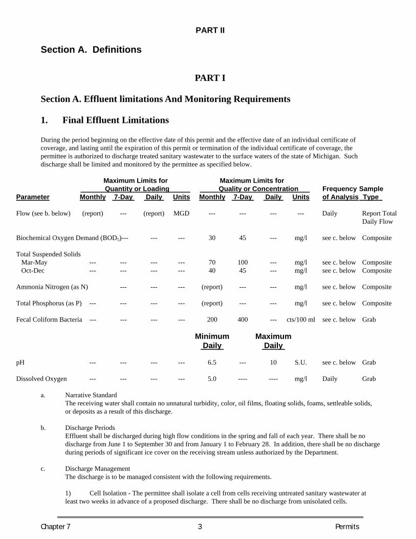
PART II
Section A. Definitions
Chapter 7 3 Permits
PART I
Section A. Effluent limitations And Monitoring Requirements
1. Final Effluent Limitations During the period beginning on the effective date of this permit and the effective date of an individual certificate of coverage, and lasting until the expiration of this permit or termination of the individual certificate of coverage, the permittee is authorized to discharge treated sanitary wastewater to the surface waters of the state of Michigan. Such discharge shall be limited and monitored by the permittee as specified below.
Maximum Limits for Maximum Limits for Quantity or Loading Quality or Concentration Frequency Sample Parameter Monthly 7-Day Daily Units Monthly 7-Day Daily Units of Analysis Type Flow (see b. below) (report) --- (report) MGD --- --- --- --- Daily Report Total Daily Flow Biochemical Oxygen Demand (BOD5)--- --- --- 30 45 --- mg/l see c. below Composite Total Suspended Solids Mar-May --- --- --- --- 70 100 --- mg/l see c. below Composite Oct-Dec --- --- --- --- 40 45 --- mg/l see c. below Composite Ammonia Nitrogen (as N) --- --- --- (report) --- --- mg/l see c. below Composite Total Phosphorus (as P) --- --- --- --- (report) --- --- mg/l see c. below Composite Fecal Coliform Bacteria --- --- --- --- 200 400 --- cts/100 ml see c. below Grab Minimum Maximum Daily Daily pH --- --- --- --- 6.5 --- 10 S.U. see c. below Grab Dissolved Oxygen --- --- --- --- 5.0 ---- ---- mg/l Daily Grab
a. Narrative Standard The receiving water shall contain no unnatural turbidity, color, oil films, floating solids, foams, settleable solids, or deposits as a result of this discharge.
b. Discharge Periods
Effluent shall be discharged during high flow conditions in the spring and fall of each year. There shall be no discharge from June 1 to September 30 and from January 1 to February 28. In addition, there shall be no discharge during periods of significant ice cover on the receiving stream unless authorized by the Department.
c. Discharge Management
The discharge is to be managed consistent with the following requirements.
1) Cell Isolation - The permittee shall isolate a cell from cells receiving untreated sanitary wastewater at least two weeks in advance of a proposed discharge. There shall be no discharge from unisolated cells.
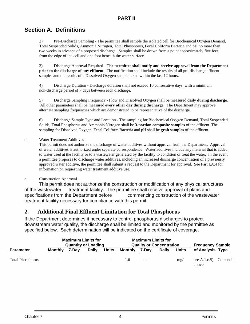
PART II
Section A. Definitions
Chapter 7 4 Permits
2) Pre-Discharge Sampling - The permittee shall sample the isolated cell for Biochemical Oxygen Demand, Total Suspended Solids, Ammonia Nitrogen, Total Phosphorus, Fecal Coliform Bacteria and pH no more than two weeks in advance of a proposed discharge. Samples shall be drawn from a point approximately five feet from the edge of the cell and one foot beneath the water surface. 3) Discharge Approval Required - The permittee shall notify and receive approval from the Department prior to the discharge of any effluent. The notification shall include the results of all pre-discharge effluent samples and the results of a Dissolved Oxygen sample taken within the last 12 hours. 4) Discharge Duration - Discharge duration shall not exceed 10 consecutive days, with a minimum non-discharge period of 7 days between each discharge. 5) Discharge Sampling Frequency - Flow and Dissolved Oxygen shall be measured daily during discharge. All other parameters shall be measured every other day during discharge. The Department may approve alternate sampling frequencies which are demonstrated to be representative of the discharge. 6) Discharge Sample Type and Location - The sampling for Biochemical Oxygen Demand, Total Suspended Solids, Total Phosphorus and Ammonia Nitrogen shall be 3-portion composite samples of the effluent. The sampling for Dissolved Oxygen, Fecal Coliform Bacteria and pH shall be grab samples of the effluent.
d. Water Treatment Additives This permit does not authorize the discharge of water additives without approval from the Department. Approval of water additives is authorized under separate correspondence. Water additives include any material that is added to water used at the facility or to a wastewater generated by the facility to condition or treat the water. In the event a permittee proposes to discharge water additives, including an increased discharge concentration of a previously approved water additive, the permittee shall submit a request to the Department for approval. See Part I.A.4 for information on requesting water treatment additive use.
e. Construction Approval This permit does not authorize the construction or modification of any physical structures of the wastewater treatment facility. The permittee shall receive approval of plans and specifications from the Department before commencing construction of the wastewater treatment facility necessary for compliance with this permit.
2. Additional Final Effluent Limitation for Total Phosphorus If the Department determines it necessary to control phosphorus discharges to protect downstream water quality, the discharge shall be limited and monitored by the permittee as specified below. Such determination will be indicated on the certificate of coverage.
Maximum Limits for Maximum Limits for Quantity or Loading Quality or Concentration Frequency Sample Parameter Monthly 7-Day Daily Units Monthly 7-Day Daily Units of Analysis Type Total Phosphorus --- --- --- --- 1.0 --- --- mg/l see A.1.c.5) Composite above

PART II
Section A. Definitions
Chapter 7 5 Permits
3. Facility Operation and Maintenance The permittee shall comply with the inspection, operation and maintenance program requirements specified below. An alternate facility operations program may be approved by the Department. a. Lagoon Inspection
The permittee shall inspect the lagoon facilities three times weekly year-round unless otherwise authorized by the Department. These inspections shall include: 1) the lagoon dikes for vegetative growth, erosion, slumping, animal burrowing or breakthrough, and condition of lagoon liner; 2) the lagoon for growth of aquatic plants, offensive odors, insect infestations, scum, floating sludge, and septic conditions; 3) the depth of the water in each cell and the freeboard;
4) the control structures and pump stations to assure that valves, gates and alarms are set correctly and properly functioning;
5) the lagoon security fence and warning signs; and
6) analysis for Dissolved Oxygen in each lagoon cell at least one time weekly, except when the lagoons are ice covered.
The permittee shall initiate steps to correct any condition that is not in accordance with the facility maintenance program outlined in Part I.A.3.b. of this permit. A record of the inspections shall be maintained by the permittee for a period of three years.
b. Facility Maintenance
The permittee shall implement a Facility Maintenance Program that incorporates the following management practices unless otherwise authorized by the Department.
1) Vegetation shall be maintained at a height not more than 6 inches above the ground on lagoon dikes.
2) Not more than 10% of the water surface shall be covered by floating vegetation and not more than 10% of the water perimeter may have emergent rooted aquatic plants.
3) Dike damage caused by erosion, slumping or animal burrowing shall be corrected immediately and steps taken to prevent occurrences in the future. 4) The integrity of the lagoon liner shall be protected. Liner damages shall be corrected immediately and steps taken to prevent future occurrences. 5) The occurrence of scum, floating sludge, offensive odors, insect infestations, and septic conditions shall be minimized.
6) A schedule for the inspection and maintenance of the collection system, lift stations, mechanical and electrical systems, transfer stations, and control structures shall be developed and implemented.
PART II
Section A. Definitions
Chapter 7 6 Permits
c. Lagoon Drawdown ConditionsThe permittee shall observe the following conditions when drawing down a cell for transfer or discharge unlessotherwise authorized by the Department.
1) Water discharged shall be removed from the surface two feet of the cell at a rate of less than one foot perday.
2) The permittee shall maintain a minimum of two feet of freeboard in all cells at all times. Upon writtennotification, the Department may require a minimum of three feet of freeboard for larger systems.
3) The permittee shall maintain a minimum of two feet of water in all cells at all times.
4. Request for Discharge of Water Treatment AdditivesIn the event a permittee proposes to discharge water additives, the permittee shall submit a request to discharge water additives to the Department for approval. Such requests shall be sent to the Surface Water Quality Assessment Section, Water Division, Department of Environmental Quality, P.O. Box 30458, Lansing, Michigan 48909, with a copy to the Department contact listed on the cover page of this permit. Instructions to submit a request electronically may be obtained via the Internet (http://www.michigan.gov/deq and on the left side of the screen click on Water, Water Quality Monitoring, and Assessment of Michigan Waters; then click on the Water Treatment Additive List which is under the Information banner). Written approval from the Department to discharge such additives at specified levels shall be obtained prior to discharge by the permittee. Additional monitoring and reporting may be required as a condition for the approval to discharge the additive.
A request to discharge water additives shall include all of the following water additive usage and discharge information:
a. Material Safety Data Sheet;
b. the proposed water additive discharge concentration;
c. the discharge frequency (i.e., number of hours per day and number of days per year);
d. the monitoring point from which the product is to be discharged;
e. the type of removal treatment, if any, that the water additive receives prior to discharge;
f. product function (i.e. microbiocide, flocculant, etc.);
g. a 48-hour LC50 or EC50 for a North American freshwater planktonic crustacean (either Ceriodaphnia sp., Daphniasp., or Simocephalus sp.); and
h. the results of a toxicity test for one other North American freshwater aquatic species (other than a planktoniccrustacean) that meets a minimum requirement of Rule 323.1057(2) of the Water Quality Standards.
Prior to submitting the request, the permittee may contact the Surface Water Quality Assessment Section by telephone at 517-335-1180 or via the Internet at the address given above to determine if the Department has the product toxicity data required by items g. and h. above. If the Department has the data, the permittee will not need to submit product toxicity data.
PART II
Section A. Definitions
Chapter 7 7 Permits
5. Special Condition – Testing for Lagoon Exfiltration/Leakage If the Department determines the permittee needs to conduct an exfiltration test on the wastewater stabilization lagoon to verify and assure the control of leakage to the groundwaters and/or surface waters of the state, the following conditions shall apply. a. Within 120 days of notification by the Department, the permittee shall submit an approvable lagoon exfiltration study
plan to the Department. The purpose of the study plan is to verify the integrity of the lagoon seal or determine the rate of leakage from the lagoon treatment system. The study shall include procedures, time schedules, staff, sampling locations, sampling frequencies, and sampling methods used, as appropriate.
b. Within 60 days of approval of the lagoon exfiltration study plan, the permittee shall implement the study plan. c. Within 1 year of approval of the study plan, the permittee shall complete and submit a final report on the lagoon
exfiltration study with supporting data to the Department. Based on review of the findings, the Department may continue the general permit coverage or terminate the Certificate of Coverage by requiring the permittee to apply for and obtain an individual NPDES permit for the discharge.
6. Residuals Management Program for Land Application of Biosolids It is understood the permittee does not currently land apply biosolids or prepare biosolids for land application, and therefore is not required to immediately develop a Residuals Management Program (RMP) in accordance with the Part 24 Rules of the Michigan Administrative Code. Alternative biosolids recycling and/or disposal activities, including incineration and landfilling, shall be conducted in accordance with Part II.D.7. of this permit. In the event the permittee proposes to prepare biosolids for land application or land apply biosolids, an RMP shall be submitted to the Department for approval, and implemented as follows:
a. Program Development
At a minimum, the program submittal shall include: 1) a description of the type and size of facility generating the biosolids; 2) a description of the biosolids treatment processes including the volume of biosolids generated from each process; 3) storage volume provided, if applicable; 4) transportation methods and spill prevention plan; 5) a description of the land application method; 6) a listing of the required information on all land application sites, information on initial application notifications required by R323.2408 and class B biosolids site restriction notifications, if applicable, as specified in R323.2414(3)(f); 7) a land application plan which shows compliance with the applicable management requirements identified in R323.2410 and the loading rates and limitations as specified in R323.2408, R323.2409 and R323.2417; 8) a description of the pathogen reduction method used to comply with R323.2411, R323.2414 and R323.2418; 9) a description of the vector attraction reduction method used to comply with R323.2415; and 10) information on monitoring program, monitoring frequencies pursuant to R323.2412, and one year of records representing the volume and concentrations of pollutants in the biosolids.
b. RMP Implementation The permittee shall implement the RMP immediately upon approval from the Department. Upon RMP approval,
the permittee may land apply bulk biosolids, and the approved RMP becomes an enforceable requirement of this permit.
PART II
Section A. Definitions
Chapter 7 8 Permits
c. Modifications to the Approved RMP The permittee shall submit proposed modifications to its RMP to the Department for approval. The approved
modification shall become effective upon the date of approval. Upon written notification, the Department may impose additional requirements and/or limitations to the approved RMP as necessary to protect public health and the environment from any adverse effect of a pollutant in the biosolids.
d. Recordkeeping Records required by R323.2413 shall be kept for a minimum of five years. However, the records documenting cumulative loading for sites subject to cumulative pollutant loading rates shall be kept as long as the site receives biosolids.
e. Annual Report The permittee shall report the number of dry tons of biosolids generated that were applied to the land in the State of Michigan in the state fiscal year (October 1 through September 30). The annual report shall include information required in R323.2413(2)(h) and R323.2413 (3) to (8), except R323.2413 (6)(b), (7)(b), and (8)(b). The report shall be submitted to the Department on or before October 30 of each year.
7. Facility Contact The “Facility Contact” was specified in the application. The permittee may replace the facility contact at any time, and shall notify the Department in writing within 10 days after replacement (including the name, address and telephone number of the new facility contact). a. The facility contact shall be (or a duly authorized representative of this person):
• for a corporation, a principal executive officer of at least the level of vice president, or a designated representative, if the representative is responsible for the overall operation of the facility from which the discharge described in the permit application or other NPDES form originates,
• for a partnership, a general partner, • for a sole proprietorship, the proprietor, or • for a municipal, state, or other public facility, either a principal executive officer, the
mayor, village president, city or village manager or other duly authorized employee. b. A person is a duly authorized representative only if:
• the authorization is made in writing to the Department by a person described in paragraph a. of this section; and
• the authorization specifies either an individual or a position having responsibility for the overall operation of the regulated facility or activity such as the position of plant manager, operator of a well or a well field, superintendent, position of equivalent responsibility, or an individual or position having overall responsibility for environmental matters for the facility (a duly authorized representative may thus be either a named individual or any individual occupying a named position).
Nothing in this section obviates the permittee from properly submitting reports and forms as required by law.
8. Connection to Public Sanitary Sewer System All wastewaters from private facilities shall be connected to public sanitary sewer systems made available by any local governmental unit, within (18) months from the date when said sewer system becomes available. At that time, discharges to surface waters are no longer authorized and the certificate of coverage shall be terminated.

PART II
Section A. Definitions
Chapter 7 9 Permits
9. Expiration and Reissuance If the permittee wishes to continue a discharge authorized under this permit beyond the permit’s expiration date, the permittee shall submit a written request to the Department on or before October 1, 2008. A person holding a valid certificate of coverage under an expired general permit shall continue to be subject to the terms and conditions of the expired permit until the permit is terminated, revoked, or reissued. If this permit is modified or reissued, the permittee shall: a) request coverage under the modified or reissued permit, b) apply for an individual NPDES permit, or c) request termination of discharge authorization. Lacking an adequate response, the permittee’s authorization to discharge shall expire on the effective date of the reissued or modified permit. If this permit is terminated or revoked, all authorizations to discharge under the permit shall expire on the date of termination or revocation.
10. Requirement to Obtain Individual Permit The Department may require any person who is authorized to discharge by a certificate of coverage and this permit, to apply for and obtain an individual NPDES permit if any of the following circumstances apply: a. the discharge is a significant contributor to pollution as determined by the Department on a case-by-case basis; b. the discharger is not complying or has not complied with the conditions of the permit; c. a change has occurred in the availability of demonstrated technology or practices for the control or abatement of
waste applicable to the point source discharge; d. effluent standards and limitations are promulgated for point source discharges subject to this permit; and e. the Department determines that the criteria under which the permit was issued no longer apply. Any person may request the Department to take action pursuant to the provisions of Rule 2191 (Rule 323.2191 of the Michigan Administrative Code). This list of definitions may include terms not applicable to this permit. Acute toxic unit (TUa) means 100/LC50 where the LC50 is determined from a whole effluent toxicity (WET) test which produces a result that is statistically or graphically estimated to be lethal to 50% of the test organisms. Bioaccumulative chemical of concern (BCC) means a chemical which, upon entering the surface waters, by itself or as its toxic transformation product, accumulates in aquatic organisms by a human health bioaccumulation factor of more than 1000 after considering metabolism and other physiochemical properties that might enhance or inhibit bioaccumulation. The human health bioaccumulation factor shall be derived according to R 323.1057(5). Chemicals with half-lives of less than 8 weeks in the water column, sediment, and biota are not BCCs. The minimum bioaccumulation concentration factor (BAF) information needed to define an organic chemical as a BCC is either a field-measured BAF or a BAF derived using the biota-sediment accumulation factor (BSAF) methodology. The minimum BAF information needed to define an inorganic chemical as a BCC, including an organometal, is either a field-measured BAF or a laboratory-measured bioconcentration factor (BCF). The BCCs to which these rules apply are identified in Table 5 of R 323.1057 of the Water Quality Standards.
PART II
Section A. Definitions
Chapter 7 10 Permits
Biosolids are the solid, semisolid, or liquid residues generated during the treatment of sanitary sewage or domestic sewage in a treatment works. This includes, but is not limited to, scum or solids removed in primary, secondary, or advanced wastewater treatment processes and a derivative of the removed scum or solids. Bulk biosolids means biosolids that are not sold or given away in a bag or other container for application to a lawn or home garden. Chronic toxic unit (TUc ) means 100/MATC or 100/IC25, where the maximum acceptable toxicant concentration (MATC) and IC25 are expressed as a percent effluent in the test medium. Class B Biosolids refers to material that has met the Class B pathogen reduction requirements or equivalent treatment by a Process to Significantly Reduce Pathogens (PSRP) in accordance with the Part 24 Rules. Processes include aerobic digestion, composting, anaerobic digestion, lime stabilization and air drying. Daily concentration is the sum of the concentrations of the individual samples of a parameter divided by the number of samples taken during any calendar day. If the parameter concentration in any sample is less than the quantification limit, regard that value as zero when calculating the daily concentration. The daily concentration will be used to determine compliance with any maximum and minimum daily concentration limitations (except for pH and dissolved oxygen). When required by the permit, report the maximum calculated daily concentration for the month in the “MAXIMUM” column under “QUALITY OR CONCENTRATION” on the Discharge Monitoring Reports (DMRs). For pH, report the maximum value of any individual sample taken during the month in the “MAXIMUM” column under “QUALITY OR CONCENTRATION” on the DMRs and the minimum value of any individual sample taken during the month in the “MINIMUM” column under “QUALITY OR CONCENTRATION” on the DMRs. For dissolved oxygen, report the minimum concentration of any individual sample in the “MINIMUM” column under “QUALITY OR CONCENTRATION” on the DMRs. Daily loading is the total discharge by weight of a parameter discharged during any calendar day. This value is calculated by multiplying the daily concentration by the total daily flow and by the appropriate conversion factor. The daily loading will be used to determine compliance with any maximum daily loading limitations. When required by the permit, report the maximum calculated daily loading for the month in the “MAXIMUM” column under “QUANTITY OR LOADING” on the DMRs. Department means the Michigan Department of Environmental Quality. Detection Level means the lowest concentration or amount of the target analyte that can be determined to be different from zero by a single measurement at a stated level of probability. EC50 means a statistically or graphically estimated concentration that is expected to cause 1 or more specified effects in 50% of a group of organisms under specified conditions. Fecal coliform bacteria monthly is the geometric mean of the samples collected in a calendar month (or 30 consecutive days). The calculated monthly value will be used to determine compliance with the maximum monthly fecal coliform bacteria limitations. When required by the permit, report the calculated monthly value in the “AVERAGE” column under “QUALITY OR CONCENTRATION” on the DMRs. Fecal coliform bacteria 7-day is the geometric mean of the samples collected in any 7-day period. The calculated 7-day value will be used to determine compliance with the maximum 7-day fecal coliform bacteria limitations. When required by the permit, report the maximum calculated 7-day concentration for the month in the “MAXIMUM” column under “QUALITY OR CONCENTRATION” on the DMRs.
PART II
Section A. Definitions
Chapter 7 11 Permits
Flow Proportioned sample is a composite sample with the sample volume proportional to the effluent flow. Grab sample is a single sample taken at neither a set time nor flow. IC25 means the toxicant concentration that would cause a 25% reduction in a nonquantal biological measurement for the test population. Interference is a discharge which, alone or in conjunction with a discharge or discharges from other sources, both: 1) inhibits or disrupts the POTW, its treatment processes or operations, or its sludge processes, use or disposal; and 2) therefore, is a cause of a violation of any requirement of the POTW's NPDES permit (including an increase in the magnitude or duration of a violation) or, of the prevention of sewage sludge use or disposal in compliance with the following statutory provisions and regulations or permits issued thereunder (or more stringent state or local regulations): Section 405 of the Clean Water Act, the Solid Waste Disposal Act (SWDA) (including Title II, more commonly referred to as the Resource Conservation and Recovery Act (RCRA), and including state regulations contained in any state sludge management plan prepared pursuant to Subtitle D of the SWDA), the Clean Air Act, the Toxic Substances Control Act, and the Marine Protection, Research and Sanctuaries Act. [This definition does not apply to sample matrix interference.] Land Application means spraying or spreading biosolids or a biosolids derivative onto the land surface, injecting below the land surface, or incorporating into the soil so that the biosolids or biosolids derivative can either condition the soil or fertilize crops or vegetation grown in the soil. LC50 means a statistically or graphically estimated concentration that is expected to be lethal to 50% of a group of organisms under specified conditions. Maximum acceptable toxicant concentration (MATC) means the concentration obtained by calculating the geometric mean of the lower and upper chronic limits from a chronic test. A lower chronic limit is the highest tested concentration that did not cause the occurrence of a specific adverse effect. An upper chronic limit is the lowest tested concentration which did cause the occurrence of a specific adverse effect and above which all tested concentrations caused such an occurrence. MGD means million gallons per day. Monthly frequency of analysis refers to a calendar month. When required by this permit, an analytical result, reading, value or observation must be reported for that period if a discharge occurs during that period. Monthly concentration is the sum of the daily concentrations determined during a reporting month (or 30 consecutive days) divided by the number of daily concentrations determined. The calculated monthly concentration will be used to determine compliance with any maximum monthly concentration limitations. When required by the permit, report the calculated monthly concentration in the “AVERAGE” column under “QUALITY OR CONCENTRATION” on the DMRs. For minimum percent removal requirements, the monthly influent concentration and the monthly effluent concentration shall be determined. The calculated monthly percent removal, which is equal to 100 times the quantity [1 minus the quantity (monthly effluent concentration divided by the monthly influent concentration)], shall be reported in the "MINIMUM" column under "QUALITY OR CONCENTRATION" on the DMRs. Monthly loading is the sum of the daily loadings of a parameter divided by the number of daily loadings determined in the reporting month (or 30 consecutive days). The calculated monthly loading will be used to determine compliance with any maximum monthly loading limitations. When required by the permit, report the calculated monthly loading in the “AVERAGE” column under “QUANTITY OR LOADING” on the DMRs. National Pretreatment Standards are the regulations promulgated by or to be promulgated by the Federal Environmental Protection Agency pursuant to Section 307(b) and (c) of the Federal Act. The standards establish nationwide limits for specific industrial categories for discharge to a POTW.
PART II
Section A. Definitions
Chapter 7 12 Permits
NOAEL means the highest tested dose or concentration of a substance that results in no observed adverse effect in exposed test organisms where higher doses or concentrations result in an adverse effect. Noncontact Cooling Water is water used for cooling which does not come into direct contact with any raw material, intermediate product, by-product, waste product or finished product. Nondomestic user is any discharger to a POTW that discharges wastes other than or in addition to water-carried wastes from toilet, kitchen, laundry, bathing or other facilities used for household purposes. Pretreatment is reducing the amount of pollutants, eliminating pollutants, or altering the nature of pollutant properties to a less harmful state prior to discharge into a public sewer. The reduction or alteration can be by physical, chemical, or biological processes, process changes, or by other means. Dilution is not considered pretreatment unless expressly authorized by an applicable National Pretreatment Standard for a particular industrial category. POTW is a publicly owned treatment works. Quantification level means the measurement of the concentration of a contaminant obtained by using a specified laboratory procedure calculated at a specified concentration above the detection level. It is considered the lowest concentration at which a particular contaminant can be quantitatively measured using a specified laboratory procedure for monitoring of the contaminant. Quarterly frequency of analysis refers to a three month period, defined as January through March, April through June, July through September, and October through December. When required by this permit, an analytical result, reading, value or observation must be reported for that period if a discharge occurs during that period. Regional Administrator is the Region 5 Administrator, U.S. EPA, located at R-19J, 77 W. Jackson Blvd., Chicago, Illinois 60604. Significant industrial user is a nondomestic user that: 1) is subject to Categorical Pretreatment Standards under 40 CFR 403.6 and 40 CFR Chapter I, Subchapter N; or 2) discharges an average of 25,000 gallons per day or more of process wastewater to a POTW (excluding sanitary, noncontact cooling and boiler blowdown wastewater); contributes a process wastestream which makes up five (5) percent or more of the average dry weather hydraulic or organic capacity of the POTW treatment plant; or is designated as such by the permittee as defined in 40 CFR 403.12(a) on the basis that the industrial user has a reasonable potential for adversely affecting the POTW's treatment plant operation or violating any pretreatment standard or requirement (in accordance with 40 CFR 403.8(f)(6)). Tier I value means a value for aquatic life, human health or wildlife calculated under R 323.1057 of the Water Quality Standards using a tier I toxicity database. Tier II value means a value for aquatic life, human health or wildlife calculated under R 323.1057 of the Water Quality Standards using a tier II toxicity database. Toxicity Reduction Evaluation (TRE) means a site-specific study conducted in a stepwise process designed to identify the causative agents of effluent toxicity, isolate the sources of toxicity, evaluate the effectiveness of toxicity control options, and then confirm the reduction in effluent toxicity. Water Quality Standards means the Part 4 Water Quality Standards promulgated pursuant to Part 31 of Act No. 451 of the Public Acts of 1994, as amended, being Rules 323.1041 through 323.1117 of the Michigan Administrative Code. Weekly frequency of analysis refers to a calendar week which begins on Sunday and ends on Saturday. When required by this permit, an analytical result, reading, value or observation must be reported for that period if a discharge occurs during that period.
PART II
Section A. Definitions Yearly frequency of analysis refers to a calendar year beginning on January 1 and ending on December 31. When required by this permit, an analytical result, reading, value or observation must be reported for that period if a discharge occurs during that period. 24-Hour Composite sample is a flow proportioned composite sample consisting of hourly or more frequent portions that are taken over a 24-hour period. 3-Portion Composite sample is a sample consisting of three equal volume grab samples collected at equal intervals over an 8-hour period. 7-day concentration is the sum of the daily concentrations determined during any 7 consecutive days in a reporting month divided by the number of daily concentrations determined. The calculated 7-day concentration will be used to determine compliance with any maximum 7-day concentration limitations. When required by the permit, report the maximum calculated 7-day concentration for the month in the “MAXIMUM” column under “QUALITY OR CONCENTRATION” on the DMRs. 7-day loading is the sum of the daily loadings of a parameter divided by the number of daily loadings determined during any 7 consecutive days in a reporting month. The calculated 7-day loading will be used to determine compliance with any maximum 7-day loading limitations. When required by the permit, report the maximum calculated 7-day loading for the month in the “MAXIMUM” column under “QUANTITY OR LOADING” on the DMRs.
Preventing
Chapter 7 13 Permits
Pollution is the Best Solution
The Michigan Department of Environmental Quality (DEQ) encourages you to consider pollution prevention alternatives. In some cases pollution prevention may allow you to avoid the need to discharge pollutants which would otherwise require permit limitations -- or even avoid the need for permits altogether! Pollution prevention can:
Save Money Reduce Waste Aid Permit Compliance Protect Our Environment Improve Corporate Image Reduce Liability
The DEQ is helping Michigan’s industries save money, reduce waste and protect our environment through pollution prevention. DEQ staff can provide pollution prevention assistance through telephone consultations, technical workshops and seminars, and informational publications. They can also put you directly in touch with local support networks and national pollution prevention resources. For more information, contact the Michigan Department of Environmental Quality, Environmental Science and Services Division, at 1-800-662-9278 or visit our homepage at http://www.michigan.gov/deq.
PART II
Section B. Monitoring Procedures
Chapter 7 14 Permits
1. Representative SamplesSamples and measurements taken as required herein shall be representative of the volume and nature of the monitored discharge.
2. Test ProceduresTest procedures for the analysis of pollutants shall conform to regulations promulgated pursuant to Section 304(h) of the Federal Act (40 CFR Part 136 - Guidelines Establishing Test Procedures for the Analysis of Pollutants), unless specified otherwise in this permit. Requests to use test procedures not promulgated under 40 CFR Part 136 for pollutant monitoring required by this permit shall be made in accordance with the Alternate Test Procedures regulations specified in 40 CFR 136.4. These requests shall be submitted to the Chief of the Permits Section, Water Resources Division, Michigan Department of Environmental Quality, P.O. Box 30458, Lansing, Michigan, 48909-7773. The permittee may use such procedures upon approval.
The permittee shall periodically calibrate and perform maintenance procedures on all analytical instrumentation at intervals to ensure accuracy of measurements. The calibration and maintenance shall be performed as part of the permittee’s laboratory Quality Control/Quality Assurance program.
3. InstrumentationThe permittee shall periodically calibrate and perform maintenance procedures on all monitoring instrumentation at intervals to ensure accuracy of measurements.
4. Recording ResultsFor each measurement or sample taken pursuant to the requirements of this permit, the permittee shall record the following information: 1) the exact place, date, and time of measurement or sampling; 2) the person(s) who performed the measurement or sample collection; 3) the dates the analyses were performed; 4) the person(s) who performed the analyses; 5) the analytical techniques or methods used; 6) the date of and person responsible for equipment calibration; and 7) theresults of all required analyses.
5. Records RetentionAll records and information resulting from the monitoring activities required by this permit including all records of analyses performed and calibration and maintenance of instrumentation and recordings from continuous monitoring instrumentation shall be retained for a minimum of three (3) years, or longer if requested by the Regional Administrator or the Department.
PART II
Section C. Reporting Requirements
Chapter 7 15 Permits
1. Start-up NotificationIf the permittee will not discharge during the first 60 days following the effective date of the facility’s certificate of coverage, the permittee shall notify the Department within 14 days following the effective date of the certificate of coverage, and then 60 days prior to the commencement of the discharge.
2. Submittal Requirements for Self-Monitoring DataUnless instructed on the effluent limits page to conduct "retained self-monitoring,” the permittee shall submit self-monitoring data on the Environmental Protection Agency's Discharge Monitoring Report (DMR) forms (monthly summary information) and the Department's Daily Discharge Monitoring Report forms (daily information) to PCS-Data Entry, Water Resources Division, Michigan Department of Environmental Quality, P.O. Box 30458, Lansing, Michigan, 48909-7958, for each calendar month of the authorized discharge period(s). The forms shall be postmarked no later than the 10th day of the month following each month of the authorized discharge period(s).
Alternative Daily Discharge Monitoring Report formats may be used if they provide equivalent reporting details and are approved by the Department. For information on electronic submittal of this information, contact the Department.
3. Retained Self-Monitoring RequirementsIf instructed on the effluent limits page (or otherwise authorized by the Department in accordance with the provisions of this permit) to conduct retained self-monitoring, the permittee shall maintain a year-to-date log of retained self-monitoring results and, upon request, provide such log for inspection to the staff of the Department (Department as defined on the certificate of coverage). Retained self-monitoring results are public information and shall be promptly provided to the public upon written request from the public.
The permittee shall certify, in writing, to the Department, on or before January 10th of each year, that: 1) all retained self-monitoring requirements have been complied with and a year-to-date log has been maintained; and 2) the application on which this permit is based still accurately describes the discharge. With this annual certification, the permittee shall submit a summary of the previous year’s monitoring data. The summary shall include maximum values for samples to be reported as daily maximums and/or monthly maximums and minimum values for any daily minimum samples.
Retained self-monitoring may be denied to a permittee by notification in writing from the Department. In such cases, the permittee shall submit self-monitoring data in accordance with Part II.C.2., above. Such a denial may be rescinded by the Department upon written notification to the permittee.
Reissuance or modification of this permit or reissuance or modification of an individual permittee’s authorization to discharge shall not affect previous approval or denial for retained self-monitoring unless the Department provides notification in writing to the permittee.
4. Additional Monitoring by PermitteeIf the permittee monitors any pollutant at the location(s) designated herein more frequently than required by this permit, using approved analytical methods as specified above, the results of such monitoring shall be included in the calculation and reporting of the values required in the Discharge Monitoring Report. Such increased frequency shall also be indicated.
Monitoring required pursuant to Part 41 of the Michigan Act or Rule 35 of the Mobile Home Park Commission Act (Act 96 of the Public Acts of 1987) for assurance of proper facility operation shall be submitted as required by the Department.
PART II
Section C. Reporting Requirements
Chapter 7 16 Permits
5. Compliance Dates Notification Within 14 days of every compliance date specified in this permit, the permittee shall submit a written notification to the Department indicating whether or not the particular requirement was accomplished. If the requirement was not accomplished, the notification shall include an explanation of the failure to accomplish the requirement, actions taken or planned by the permittee to correct the situation, and an estimate of when the requirement will be accomplished. If a written report is required to be submitted by a specified date and the permittee accomplishes this, a separate written notification is not required.
6. Noncompliance Notification Compliance with all applicable requirements set forth in the Federal Act, Parts 31 and 41 of the Michigan Act, and related regulations and rules is required. All instances of noncompliance shall be reported as follows: a. 24-hour reporting - Any noncompliance which may endanger health or the environment (including maximum daily
concentration discharge limitation exceedances) shall be reported, verbally, within 24 hours from the time the permittee becomes aware of the noncompliance. A written submission shall also be provided within five (5) days.
b. other reporting - The permittee shall report, in writing, all other instances of noncompliance not described in a.
above at the time monitoring reports are submitted; or, in the case of retained self-monitoring, within five (5) days from the time the permittee becomes aware of the noncompliance.
Written reporting shall include: 1) a description of the discharge and cause of noncompliance; and 2) the period of noncompliance, including exact dates and times; or, if not corrected, the anticipated time the noncompliance is expected to continue, and the steps taken to reduce, eliminate and prevent recurrence of the noncomplying discharge.
7. Spill Notification The permittee shall immediately report any release of any polluting material which occurs to the surface waters or groundwaters of the state, unless the permittee has determined that the release is not in excess of the threshold reporting quantities specified in the Part 5 Rules (Rules 324.2001 through 324.2009 of the Michigan Administrative Code), by calling the Department at the number indicated in the certificate of coverage, or if the notice is provided after regular working hours call the Department’s 24-hour Pollution Emergency Alerting System telephone number, 1-800-292-4706 (calls from out-of-state dial 1-517-373-7660). Within ten (10) days of the release, the permittee shall submit to the Department a full written explanation as to the cause of the release, the discovery of the release, response (clean-up and/or recovery) measures taken, and preventative measures taken or a schedule for completion of measures to be taken to prevent reoccurrence of similar releases.
8. Upset Noncompliance Notification If a process "upset" (defined as an exceptional incident in which there is unintentional and temporary noncompliance with technology based permit effluent limitations because of factors beyond the reasonable control of the permittee) has occurred, the permittee who wishes to establish the affirmative defense of upset, shall notify the Department by telephone within 24-hours of becoming aware of such conditions; and within five (5) days, provide in writing, the following information: a. that an upset occurred and that the permittee can identify the specific cause(s) of the upset; b. that the permitted wastewater treatment facility was, at the time, being properly operated; and

PART II
Section C. Reporting Requirements
Chapter 7 17 Permits
c. that the permittee has specified and taken action on all responsible steps to minimize or correct any adverse impact in the environment resulting from noncompliance with this permit.
\In any enforcement proceedings, the permittee, seeking to establish the occurrence of an upset, has the burden of proof.
9. Bypass Prohibition and Notification a. Bypass Prohibition - Bypass is prohibited unless:
1) bypass was unavoidable to prevent loss of life, personal injury, or severe property damage; 2) there were no feasible alternatives to the bypass, such as the use of auxiliary treatment facilities, retention of untreated wastes, or maintenance during normal periods of equipment downtime. This condition is not satisfied if adequate backup equipment should have been installed in the exercise of reasonable engineering judgment to prevent a bypass; and 3) the permittee submitted notices as required under 9.b. or 9.c. below.
b. Notice of Anticipated Bypass - If the permittee knows in advance of the need for a bypass, it shall submit prior
notice to the Department, if possible at least ten (10) days before the date of the bypass, and provide information about the anticipated bypass as required by the Department. The Department may approve an anticipated bypass, after considering its adverse effects, if it will meet the three (3) conditions listed in 9.a. above.
c. Notice of Unanticipated Bypass - The permittee shall submit notice to the Department of an unanticipated bypass
by calling the Department at the number indicated in the certificate of coverage (if the notice is provided after regular working hours, use the following number: 1-800-292-4706) as soon as possible, but no later than 24 hours from the time the permittee becomes aware of the circumstances.
d. Written Report of Bypass - A written submission shall be provided within five (5) working days of commencing
any bypass to the Department, and at additional times as directed by the Department. The written submission shall contain a description of the bypass and its cause; the period of bypass, including exact dates and times, and if the bypass has not been corrected, the anticipated time it is expected to continue; steps taken or planned to reduce, eliminate, and prevent reoccurrence of the bypass; and other information as required by the Department.
e. Bypass Not Exceeding Limitations - The permittee may allow any bypass to occur which does not cause effluent
limitations to be exceeded, but only if it also is for essential maintenance to assure efficient operation. These bypasses are not subject to the provisions of 9.a., 9.b., 9.c., and 9.d., above. This provision does not relieve the permittee of any notification responsibilities under Part II.C.10. of this permit.
f. Definitions
1) Bypass means the intentional diversion of waste streams from any portion of a treatment facility. 2) Severe property damage means substantial physical damage to property, damage to the treatment facilities which causes them to become inoperable, or substantial and permanent loss of natural resources which can reasonably be expected to occur in the absence of a bypass. Severe property damage does not mean economic loss caused by delays in production.
PART II
Section C. Reporting Requirements
Chapter 7 18 Permits
10. Notification of Changes in Discharge The permittee shall notify the Department, in writing, within 10 days of knowing, or having reason to believe, that any activity or change has occurred or will occur which would result in the discharge of: 1) detectable levels of chemicals on the current Michigan Critical Materials Register, priority pollutants or hazardous substances set forth in 40 CFR 122.21, Appendix D, or the Pollutants of Initial Focus in the Great Lakes Water Quality Initiative specified in 40 CFR 132.6, Table 6, which were not acknowledged in the application or listed in the application at less than detectable levels; 2) detectable levels of any other chemical not listed in the application or listed at less than detection, for which the application specifically requested information; or 3) any chemical at levels greater than five times the average level reported in the complete application (see the certificate of coverage for the date(s) the complete application was submitted). Any other monitoring results obtained as a requirement of this permit shall be reported in accordance with the compliance schedules.
11. Changes in Facility Operations Any anticipated action or activity, including but not limited to facility expansion, production increases, or process modification, which will result in new or increased loadings of pollutants to the receiving waters must be reported to the Department by a) submission of an increased use request (application) and all information required under Rule 323.1098 (Antidegradation) of the Water Quality Standards or b) by notice if the following conditions are met: 1) the action or activity will not result in a change in the types of wastewater discharged or result in a greater quantity of wastewater than currently authorized by this permit; 2) the action or activity will not result in violations of the effluent limitations specified in this permit; 3) the action or activity is not prohibited by the requirements of Part II.C.12.; and 4) the action or activity will not require notification pursuant to Part II.C.10. Following such notice, the permit may be modified according to applicable laws and rules to specify and limit any pollutant not previously limited.
12. Bioaccumulative Chemicals of Concern (BCC) Consistent with the requirements of Rules 323.1098 and 323.1215 of the Michigan Administrative Code, the permittee is prohibited from undertaking any action that would result in a lowering of water quality from an increased loading of a BCC unless an increased use request and antidegradation demonstration have been submitted and approved by the Department.
13. Transfer of Ownership or Control In the event of any change in control or ownership of facilities from which the authorized discharge emanates, the permittee shall notify the succeeding owner or controller of the existence of this permit by letter, a copy of which shall be forwarded to the Department 30 days prior to the actual transfer of ownership or control.
1. Duty to Comply All discharges authorized herein shall be consistent with the terms and conditions of this permit and the facility’s certificate of coverage (COC). The discharge of any pollutant identified in this permit and/or the facility’s COC more frequently than or at a level in excess of that authorized shall constitute a violation of the permit. It is the duty of the permittee to comply with all the terms and conditions of this permit and the facility’s COC. Any noncompliance with the Effluent Limitations, Special Conditions, or terms of this permit or the facility’s COC constitutes a violation of the Michigan Act and/or the Federal Act and constitutes grounds for enforcement action; for COC termination, revocation and reissuance, or modification; or denial of an application for permit or COC renewal.
PART II
Section D. Management Responsibilities
Chapter 7 19 Permits
2. Operator Certification The permittee shall have the waste treatment facilities under direct supervision of an operator certified at the appropriate level for the facility certification by the Department, as required by Sections 3110 and 4104 of the Michigan Act.
3. Facilities Operation The permittee shall, at all times, properly operate and maintain all treatment or control facilities or systems installed or used by the permittee to achieve compliance with the terms and conditions of this permit. Proper operation and maintenance includes adequate laboratory controls and appropriate quality assurance procedures.
4. Power Failures In order to maintain compliance with the effluent limitations of this permit and prevent unauthorized discharges, the permittee shall either: a. provide an alternative power source sufficient to operate facilities utilized by the permittee to maintain compliance
with the effluent limitations and conditions of this permit; or b. upon the reduction, loss, or failure of one or more of the primary sources of power to facilities utilized by the
permittee to maintain compliance with the effluent limitations and conditions of this permit, the permittee shall halt, reduce or otherwise control production and/or all discharge in order to maintain compliance with the effluent limitations and conditions of this permit.
5. Adverse Impact The permittee shall take all reasonable steps to minimize any adverse impact to the surface waters or groundwaters of the state resulting from noncompliance with any effluent limitation specified in this permit including, but not limited to, such accelerated or additional monitoring as necessary to determine the nature and impact of the discharge in noncompliance.
6. Containment Facilities The permittee shall provide facilities for containment of any accidental losses of polluting materials in accordance with the requirements of the Part 5 Rules (Rules 324.2001 through 324.2009 of the Michigan Administrative Code). For a Publicly Owned Treatment Work (POTW), these facilities shall be approved under Part 41 of the Michigan Act.
7. Waste Treatment Residues Residuals (i.e. solids, sludges, biosolids, filter backwash, scrubber water, ash, grit or other pollutants) removed from or resulting from treatment or control of wastewaters, shall be disposed of in an environmentally compatible manner and according to applicable laws and rules. These laws may include, but are not limited to, the Michigan Act, Part 31 for protection of water resources, Part 55 for air pollution control, Part 111 for hazardous waste management, Part 115 for solid waste management, Part 121 for liquid industrial wastes, Part 301 for protection of inland lakes and streams, and Part 303 for wetlands protection. Such disposal shall not result in any unlawful pollution of the air, surface waters or groundwaters of the state.
PART II
Section D. Management Responsibilities 8. Treatment System Closure In the event that discharges from a treatment system are planned to be eliminated, the permittee shall submit a closure plan to the Department for approval. The closure plan shall include characterization of any wastewater and residuals which will remain on-site after the discharges are eliminated, along with disposal methods, proposed schedule, and any other relevant information as required by the Department. Closure activities involving waste treatment residuals shall be consistent with Part II.D.7. of this permit. The permittee shall implement the closure activities in accordance with the approved plan. Any wastewater or residual disposal inconsistent with the approved plan shall be considered a violation of this permit. After proper closure of the treatment system, this permit may be terminated.
9. Right of Entry The permittee shall allow the Department, any agent appointed by the Department or the Regional Administrator, upon the presentation of credentials: a. to enter upon the permittee’s premises where an effluent source is located or in which any records are required to
be kept under the terms and conditions of this permit; and b. at reasonable times to have access to and copy any records required to be kept under the terms and conditions of
this permit; to inspect process facilities, treatment works, monitoring methods and equipment regulated or required under this permit; and to sample any discharge of pollutants.
10. Availability of Reports Except for data determined to be confidential under Section 308 of the Federal Act and Rule 2128 (Rule 323.2128 of the Michigan Administrative Code), all reports prepared in accordance with the terms of this permit shall be available for public inspection at the offices of the Department and the Regional Administrator. As required by the Federal Act, effluent data shall not be considered confidential. Knowingly making any false statement on any such report may result in the imposition of criminal penalties as provided for in Section 309 of the Federal Act and Sections 3112, 3115, 4106 and 4110 of the Michigan Act.
Chapter 7 20 Permits
Chapter 7 21 Permits
1. Discharge to the Groundwaters This permit does not authorize any discharge to the groundwaters. Such discharge may be authorized by a groundwater discharge permit issued pursuant to the Michigan Act.
2. Facility Construction This permit does not authorize or approve the construction or modification of any physical structures or facilities. Approval for such construction for a POTW must be by permit issued under Part 41 of the Michigan Act. Approval for such construction for a mobile home park, campground or marina shall be from the Water Division, Michigan Department of Environmental Quality. Approval for such construction for a hospital, nursing home or extended care facility shall be from the Division of Health Facilities and Services, Michigan Department of Consumer and Industry Services upon request.
3. Civil and Criminal Liability Except as provided in permit conditions on "Bypass" (Part II.C.9. pursuant to 40 CFR 122.41(m)), nothing in this permit shall be construed to relieve the permittee from civil or criminal penalties for noncompliance, whether or not such noncompliance is due to factors beyond the permittee’s control, such as accidents, equipment breakdowns, or labor disputes.
4. Oil and Hazardous Substance Liability Nothing in this permit shall be construed to preclude the institution of any legal action or relieve the permittee from any responsibilities, liabilities, or penalties to which the permittee may be subject under Section 311 of the Federal Act except as are exempted by federal regulations.
5. State Laws Nothing in this permit shall be construed to preclude the institution of any legal action or relieve the permittee from any responsibilities, liabilities, or penalties established pursuant to any applicable state law or regulation under authority preserved by Section 510 of the Federal Act.
6. Property Rights The issuance of this permit does not convey any property rights in either real or personal property, or any exclusive privileges, nor does it authorize violation of any federal, state or local laws or regulations, nor does it obviate the necessity of obtaining such permits or approvals as may be required by law.
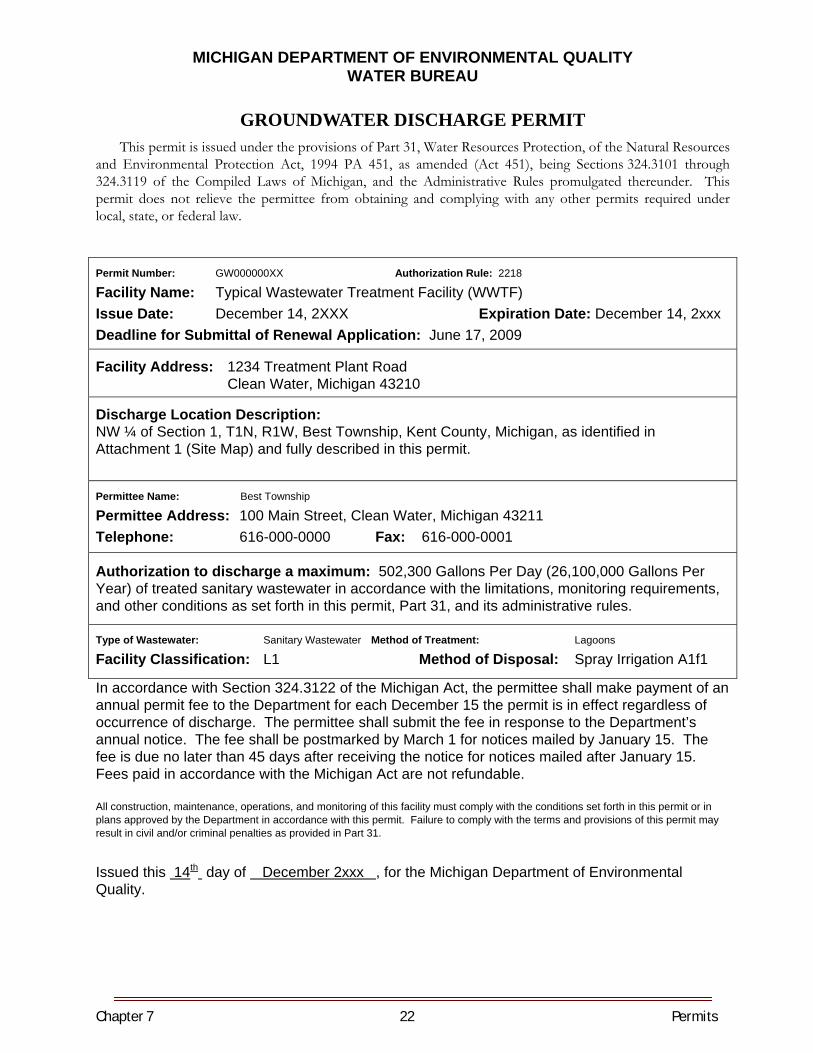
Chapter 7 22 Permits
MICHIGAN DEPARTMENT OF ENVIRONMENTAL QUALITY WATER BUREAU
GROUNDWATER DISCHARGE PERMIT This permit is issued under the provisions of Part 31, Water Resources Protection, of the Natural Resources
and Environmental Protection Act, 1994 PA 451, as amended (Act 451), being Sections 324.3101 through 324.3119 of the Compiled Laws of Michigan, and the Administrative Rules promulgated thereunder. This permit does not relieve the permittee from obtaining and complying with any other permits required under local, state, or federal law.
Permit Number: GW000000XX Authorization Rule: 2218
Facility Name: Typical Wastewater Treatment Facility (WWTF) Issue Date: December 14, 2XXX Expiration Date: December 14, 2xxx Deadline for Submittal of Renewal Application: June 17, 2009
Facility Address: 1234 Treatment Plant Road Clean Water, Michigan 43210
Discharge Location Description: NW ¼ of Section 1, T1N, R1W, Best Township, Kent County, Michigan, as identified in Attachment 1 (Site Map) and fully described in this permit.
Permittee Name: Best Township
Permittee Address: 100 Main Street, Clean Water, Michigan 43211 Telephone: 616-000-0000 Fax: 616-000-0001 Authorization to discharge a maximum: 502,300 Gallons Per Day (26,100,000 Gallons Per Year) of treated sanitary wastewater in accordance with the limitations, monitoring requirements, and other conditions as set forth in this permit, Part 31, and its administrative rules.
Type of Wastewater: Sanitary Wastewater Method of Treatment: Lagoons
Facility Classification: L1 Method of Disposal: Spray Irrigation A1f1
In accordance with Section 324.3122 of the Michigan Act, the permittee shall make payment of an annual permit fee to the Department for each December 15 the permit is in effect regardless of occurrence of discharge. The permittee shall submit the fee in response to the Department’s annual notice. The fee shall be postmarked by March 1 for notices mailed by January 15. The fee is due no later than 45 days after receiving the notice for notices mailed after January 15. Fees paid in accordance with the Michigan Act are not refundable. All construction, maintenance, operations, and monitoring of this facility must comply with the conditions set forth in this permit or in plans approved by the Department in accordance with this permit. Failure to comply with the terms and provisions of this permit may result in civil and/or criminal penalties as provided in Part 31.
Issued this 14th day of December 2xxx , for the Michigan Department of Environmental Quality.
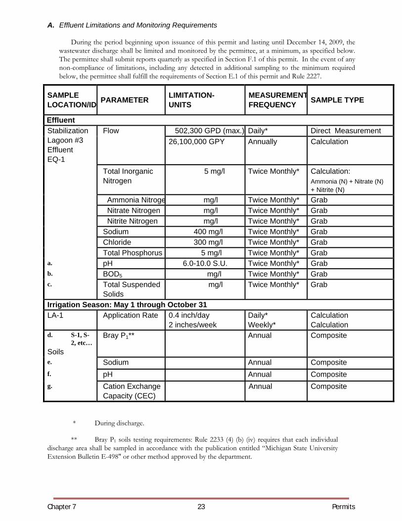
Chapter 7 23 Permits
A. Effluent Limitations and Monitoring Requirements
During the period beginning upon issuance of this permit and lasting until December 14, 2009, the wastewater discharge shall be limited and monitored by the permittee, at a minimum, as specified below. The permittee shall submit reports quarterly as specified in Section F.1 of this permit. In the event of any non-compliance of limitations, including any detected in additional sampling to the minimum required below, the permittee shall fulfill the requirements of Section E.1 of this permit and Rule 2227.
SAMPLE LOCATION/ID
PARAMETER
LIMITATION- UNITS
MEASUREMENTFREQUENCY SAMPLE TYPE
Effluent 502,300 GPD (max.) Daily* Direct Measurement Stabilization
Lagoon #3 Effluent EQ-1
Flow 26,100,000 GPY Annually Calculation
Total Inorganic Nitrogen
5 mg/l
Twice Monthly* Calculation: Ammonia (N) + Nitrate (N) + Nitrite (N)
Ammonia Nitroge mg/l Twice Monthly* Grab Nitrate Nitrogen mg/l Twice Monthly* Grab Nitrite Nitrogen mg/l Twice Monthly* Grab Sodium 400 mg/l Twice Monthly* Grab Chloride 300 mg/l Twice Monthly* Grab Total Phosphorus 5 mg/l Twice Monthly* Grab a. pH 6.0-10.0 S.U. Twice Monthly* Grab b. BOD5 mg/l Twice Monthly* Grab c. Total Suspended
Solids mg/l Twice Monthly* Grab
Irrigation Season: May 1 through October 31 LA-1 Application Rate 0.4 inch/day
2 inches/week Daily* Weekly*
Calculation Calculation
d. S-1, S-2, etc…
Soils
Bray P1** Annual Composite
e. Sodium Annual Composite f. pH Annual Composite g. Cation Exchange
Capacity (CEC) Annual Composite
* During discharge.
** Bray P1 soils testing requirements: Rule 2233 (4) (b) (iv) requires that each individual discharge area shall be sampled in accordance with the publication entitled “Michigan State University Extension Bulletin E-498" or other method approved by the department.
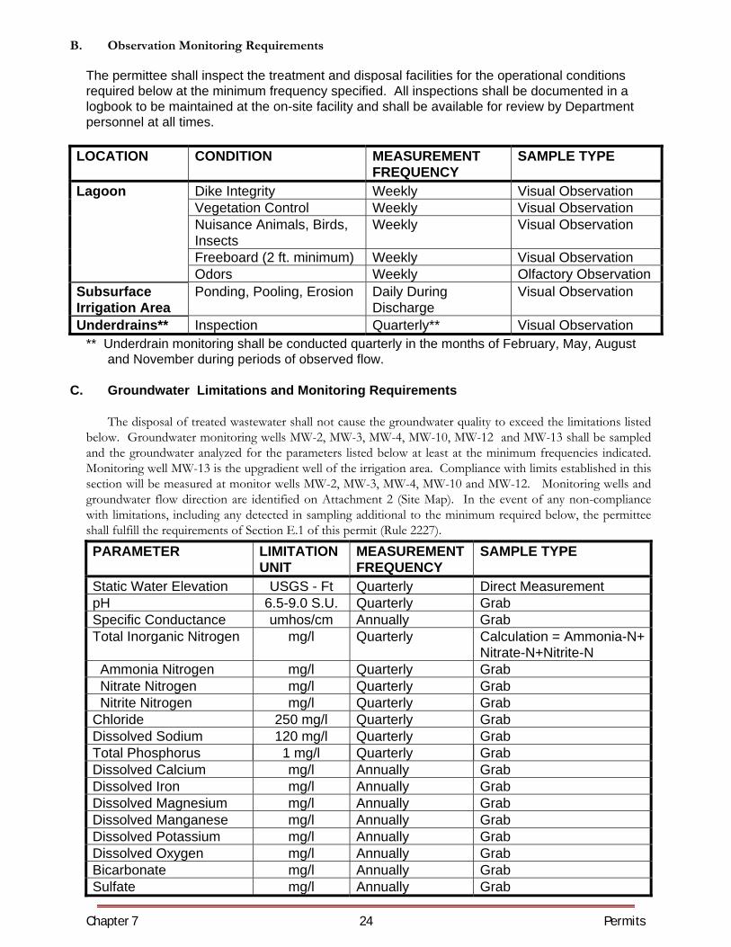
Chapter 7 24 Permits
B. Observation Monitoring Requirements
The permittee shall inspect the treatment and disposal facilities for the operational conditions required below at the minimum frequency specified. All inspections shall be documented in a logbook to be maintained at the on-site facility and shall be available for review by Department personnel at all times.
LOCATION CONDITION MEASUREMENT
FREQUENCY SAMPLE TYPE
Lagoon Dike Integrity Weekly Visual Observation Vegetation Control Weekly Visual Observation Nuisance Animals, Birds,
Insects Weekly Visual Observation
Freeboard (2 ft. minimum) Weekly Visual Observation Odors Weekly Olfactory Observation Subsurface Irrigation Area
Ponding, Pooling, Erosion Daily During Discharge
Visual Observation
Underdrains** Inspection Quarterly** Visual Observation ** Underdrain monitoring shall be conducted quarterly in the months of February, May, August
and November during periods of observed flow.
C. Groundwater Limitations and Monitoring Requirements
The disposal of treated wastewater shall not cause the groundwater quality to exceed the limitations listed below. Groundwater monitoring wells MW-2, MW-3, MW-4, MW-10, MW-12 and MW-13 shall be sampled and the groundwater analyzed for the parameters listed below at least at the minimum frequencies indicated. Monitoring well MW-13 is the upgradient well of the irrigation area. Compliance with limits established in this section will be measured at monitor wells MW-2, MW-3, MW-4, MW-10 and MW-12. Monitoring wells and groundwater flow direction are identified on Attachment 2 (Site Map). In the event of any non-compliance with limitations, including any detected in sampling additional to the minimum required below, the permittee shall fulfill the requirements of Section E.1 of this permit (Rule 2227).
PARAMETER LIMITATION UNIT
MEASUREMENT FREQUENCY
SAMPLE TYPE
Static Water Elevation USGS - Ft Quarterly Direct Measurement pH 6.5-9.0 S.U. Quarterly Grab Specific Conductance umhos/cm Annually Grab Total Inorganic Nitrogen mg/l Quarterly Calculation = Ammonia-N+
Nitrate-N+Nitrite-N Ammonia Nitrogen mg/l Quarterly Grab Nitrate Nitrogen mg/l Quarterly Grab Nitrite Nitrogen mg/l Quarterly Grab Chloride 250 mg/l Quarterly Grab Dissolved Sodium 120 mg/l Quarterly Grab Total Phosphorus 1 mg/l Quarterly Grab Dissolved Calcium mg/l Annually Grab Dissolved Iron mg/l Annually Grab Dissolved Magnesium mg/l Annually Grab Dissolved Manganese mg/l Annually Grab Dissolved Potassium mg/l Annually Grab Dissolved Oxygen mg/l Annually Grab Bicarbonate mg/l Annually Grab Sulfate mg/l Annually Grab
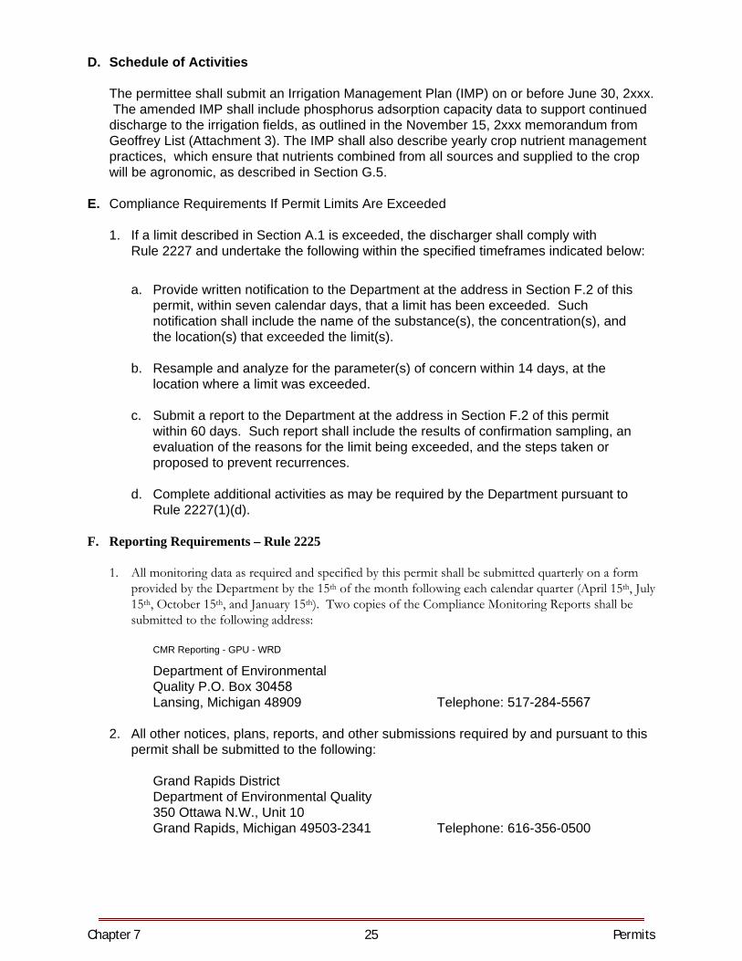
Chapter 7 25 Permits
D. Schedule of Activities
The permittee shall submit an Irrigation Management Plan (IMP) on or before June 30, 2xxx. The amended IMP shall include phosphorus adsorption capacity data to support continued discharge to the irrigation fields, as outlined in the November 15, 2xxx memorandum from Geoffrey List (Attachment 3). The IMP shall also describe yearly crop nutrient management practices, which ensure that nutrients combined from all sources and supplied to the crop will be agronomic, as described in Section G.5.
E. Compliance Requirements If Permit Limits Are Exceeded
1. If a limit described in Section A.1 is exceeded, the discharger shall comply withRule 2227 and undertake the following within the specified timeframes indicated below:
a. Provide written notification to the Department at the address in Section F.2 of thispermit, within seven calendar days, that a limit has been exceeded. Suchnotification shall include the name of the substance(s), the concentration(s), andthe location(s) that exceeded the limit(s).
b. Resample and analyze for the parameter(s) of concern within 14 days, at thelocation where a limit was exceeded.
c. Submit a report to the Department at the address in Section F.2 of this permitwithin 60 days. Such report shall include the results of confirmation sampling, anevaluation of the reasons for the limit being exceeded, and the steps taken orproposed to prevent recurrences.
d. Complete additional activities as may be required by the Department pursuant toRule 2227(1)(d).
F. Reporting Requirements – Rule 2225
1. All monitoring data as required and specified by this permit shall be submitted quarterly on a formprovided by the Department by the 15th of the month following each calendar quarter (April 15th, July15th, October 15th, and January 15th). Two copies of the Compliance Monitoring Reports shall besubmitted to the following address:
CMR Reporting - GPU - WRD
Department of Environmental Quality P.O. Box 30458 Lansing, Michigan 48909 Telephone: 517-284-5567
2. All other notices, plans, reports, and other submissions required by and pursuant to thispermit shall be submitted to the following:
Grand Rapids District Department of Environmental Quality 350 Ottawa N.W., Unit 10 Grand Rapids, Michigan 49503-2341 Telephone: 616-356-0500
Chapter 7 26 Permits
G. Other Conditions
1. Effluent shall be isolated from property lines and water supply wells as specified in Rule 2204(2)(c) and Rule 2204(2)(d)(ii).
2. The permittee shall maintain all treatment or control facilities or systems installed or used by the discharger to achieve compliance with this permit in good working order and operate the facilities or systems as efficiently as possible.
3. Pursuant to Rule 2223(1), the Department may modify the effluent or groundwater monitoring parameters or frequency requirements of this permit, or they may be modified upon the request of the permittee with adequate supporting documentation.
4. Prior to any land application of bulk biosolids, the permittee shall submit to the District
Supervisor of the Water Bureau, and receive approval of, a Residuals Management Program (RMP) that complies with the requirements of the Part 24 Rules (R 323.2401 through R 323.2418 of the Michigan Administrative Code). The permittee is authorized to land apply bulk biosolids or prepare bulk biosolids for land application in accordance with an approved RMP.
5. In no case shall nutrients provided by wastewater and supplemental fertilization by the
permittee or a third party exceed the nutrient requirements of the crop, based on the yield goal for that crop. Per Rule 2233(4)(a)(iv), if any modifications are made to the management practices or specifications for the land application of wastewater, including but not limited to changes in crops grown, yield goal for those crops, or supplemental fertilization provided by the permittee or a third party, the permittee shall submit a revised Irrigation Management Plan to the Department for review and approval. The revised Irrigation Management Plan must be submitted by November 30 of the year prior to making the proposed change.
H. Permit Application Issuance of this permit is based upon the information submitted on the Application for Groundwater Discharge (Application) and any subsequent amendments received by the Department. Any material or intentional inaccuracies found in this information, or omissions of material information, may be grounds for the revocation or modification of this permit or other enforcement action. The permittee shall inform the Grand Rapids District, Department of Environmental Quality, of any known material or intentional inaccuracies in the information of the Application which would affect the permittee’s ability to comply with the applicable rules or license conditions. The following documents were submitted to the Department as part of the Application: 1. Hydrogeological Report – June 2xxx. 2. Groundwater Quality – June 2xxx. 3. Effluent Characterization – June 2xxx.
Chapter 7 27 Permits
I. Transfer of Ownership
The permittee shall notify the Department, in writing, no less than 30 days before a change in ownership of the facility. This permit may be transferred to the new owner by written approval of the Chief of the Permits Section, Water Bureau.
J. Change or Modification of Treatment or Discharge – Rule 2218 (3)(d) and (e) The permittee, if proposing to modify the quantity or effluent characteristics of the discharge, if proposing to modify the monitoring program, or if proposing to modify the treatment process for the discharge, shall notify the Department of the proposed modification before it occurs. The Department shall determine if the proposed modification requires the permit to be modified to ensure that the terms of Rule 2204 are met. Modifications determined by the Department to be significant require that the permittee submit an application for and obtain a reissuance of the permit before such modification occurs.
K. By-Passing Any diversion from or bypass of facilities necessary to maintain compliance with the terms
and conditions of this permit is prohibited, except where unavoidable to prevent loss of life, personal injury, or severe property damage. The permittee shall immediately notify the Department of any such occurrence by telephone at 1-800-292-4706. Such notice shall be supplemented by a written report with the next operation report detailing the cause of such diversion or bypass and the corrective actions taken to minimize adverse impact and eliminate the need for future diversion or bypass.
L. Cessation of Discharge-Related Activities
If all or any portion of the permitted treatment facilities and discharge areas is intended to be eliminated, the permittee shall comply with the requirements of Rule 2226.
NOTE: IF THE PERMITTEE WISHES TO CONTINUE DISCHARGING BEYOND THE EXPIRATION DATE, THE PERMITTEE SHALL SUBMIT AN ADMINISTRATIVELY COMPLETE APPLICATION FOR REISSUANCE NO LATER THAN 180 DAYS PRIOR TO THE EXPIRATION DATE IN ACCORDANCE WITH RULE 2151 OF THE PART 21 ADMINISTRATIVE RULES. FAILURE TO SUBMIT AN ADMINISTRATIVELY COMPLETE APPLICATION FOR REISSUANCE BY THE REQUIRED DATE WILL RESULT IN TERMINATION OF THE AUTHORIZATION TO DISCHARGE ON THE EXPIRATION DATE.
(a) ATTACHMENT 1 SITE MAP
(b) ATTACHMENT 2 GROUNDWATER MONITORING WELL MAP
ATTACHMENT 3
11/15/02 Memorandum


8. Records and Reports
CHAPTER EIGHT RECORDS AND REPORTS GENERAL Forms, reports and records should be kept by the operator to be used as reference material. Accurate records are an invaluable aid for complete evaluation of treatment facilities. A complete set of as-built drawings of the facility should be available to the operator and any changes that are made, such as piping and electrical changes, should be recorded and included on these drawings. VALUE OF RECORDS Operating records are of value to lagoon operators, the municipal official, design engineer, state and federal regulatory agencies, and others interested in the performance of the lagoon system. The records may be used for comparative purposes to correlate conditions of the past with present performance and future needs. Clearly, design of improvements and additions can be more intelligently accomplished if good records are kept. Records of the performance of the waste stabilization lagoon system can be of great value to the owner of the system in the event of a law suit such as might be brought against the system as a result of nuisances claimed to originate at the lagoon or from undesirable downstream conditions alleged to result from ineffective treatment or improper control of the discharge. Even if these records are unfavorable, it is essential to know the facts so that the best course of action can be followed. The operator must know if the lagoon begins to function improperly. Municipal and state officials, and the public which bears the expense of providing and operating these facilities, are entitled to know how they are functioning and if the money being expended is warranted by the results obtained. MAINTENANCE RECORDS It is imperative that records be kept of the service requirements of all equipment in the treatment facility. Therefore, a system is needed to keep a record of maintenance. Such a system should provide a permanent record of all maintenance work completed along with preventive maintenance schedules. To be efficient, a file and/or log book should be set up which contains the following information:
1. Preventive maintenance records. 2. The preventive maintenance schedule. 3. Service record cards. 4. Where spare parts can be purchased. 5. Spare parts inventory. 6. Operation and maintenance instructions. 7. Specifications on equipment from supplier. 8. Equipment inventory.
OPERATING RECORDS Records should be maintained which indicate the amount of time spent for operation. This record sheet may contain as much information as, you, the operator, feel necessary to maintain. These operation records may provide information for performance evaluation and indicate valuable information in handling certain situations within the treatment works. Sewage flow quantities, power consumption and weather data should be recorded daily. Lagoon liquid depth, dissolved oxygen, and ice conditions should be recorded at
Chapter 8 2 Records & Reports
least once a week during the storage season and daily during discharge. The weather data should include air temperatures, rainfall, wind direction and relative velocity, and a general statement of the weather as to whether the day was sunny, cloudy, etc. Weather condition information is often helpful in evaluating the behavior or function of lagoons. For example, should the lagoons suddenly become anaerobic in mid-summer, the operating records might reveal that a sudden drop in liquid depth, resulting from a rapid transfer of liquid from one lagoon to another, had occurred just prior to several days of extremely cloudy weather. The resultant drastic change in biological and algal activity within the lagoon reduce the rate of oxygen production bringing about the anaerobic conditions. After a few sunny days the lagoon might quickly recover and become aerobic again. This analysis of a set of lagoon records would indicate that no drastic action on the part of the operator would be required to correct the anaerobic conditions. On the other hand, with the same lagoons and under sunny weather conditions, if a large quantity of food processing wastes were discharged to the sewer system the oxygen supply capability of the system could be grossly overtaxed, resulting in anaerobic conditions. In this case a decision would be required as to whether to severely restrict the amount of such wastes to be accepted into the sewers and lagoon system or to extensively expand the lagoons to provide sufficient capacity for these wastes. MONTHLY REPORTS The required monthly reports should be completed and submitted to your compliance agency. A copy of these reports should always be retained by the operator for his records, as a complete set of records will provide the basis for future design if expansion is needed, as well as serve as a legal record of operation. OPERATION AND MAINTENANCE COST RECORDS A complete record should be kept of electrical charges, cost of replacement parts, lubricant costs, etc. These records will provide the basis of estimating funding requirements, sewer charges and yearly budgets. MAINTENANCE FORMS Complete records should be kept of all maintenance duties and frequency of performance. These records are very valuable in preparing work and maintenance schedules. Sample maintenance forms are shown in the following figures.
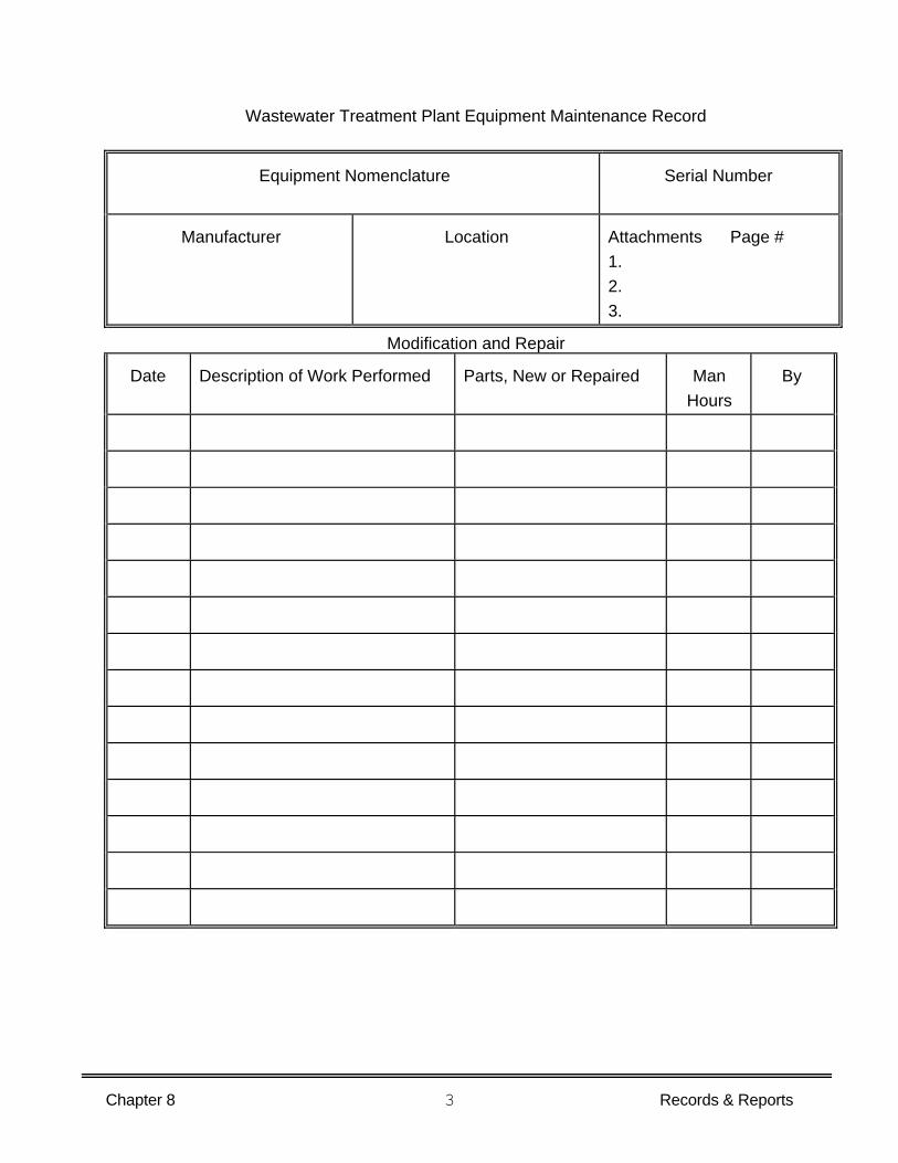
Chapter 8 3 Records & Reports
Wastewater Treatment Plant Equipment Maintenance Record
Equipment Nomenclature Serial Number
Manufacturer Location Attachments Page # 1. 2. 3.
Modification and Repair
Date Description of Work Performed Parts, New or Repaired Man Hours
By
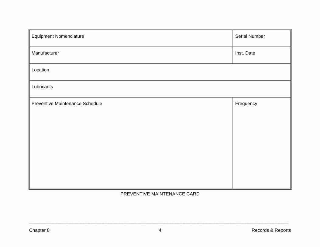
═════════════════════════════════════════════════════════════════════════════════════════════ Chapter 8 4 Records & Reports
Equipment Nomenclature Serial Number
Manufacturer Inst. Date
Location
Lubricants
Preventive Maintenance Schedule Frequency
PREVENTIVE MAINTENANCE CARD

9. Collection Systems
CHAPTER NINE
COLLECTION SYSTEMS
Wastewater collection systems are intended to be a reliable method of conveying wastewater from the dischargers to wastewater treatment facilities. Inspection and testing are the techniques used to gather information to develop operation and maintenance programs to insure that new and existing collection systems serve their intended purpose. Inspection and testing are necessary to do the following.
1. Identify existing or potential problem areas in the collection system. 2. Evaluate seriousness of detected problems. 3. Locate the position of problems. 4. Provide clear, concise and meaningful reports to supervisors regarding problems.
Two major purposes of inspecting and testing are to prevent leaks in the wastewater collection system from developing and to identify existing leaks so they can be corrected. The existence of leaks in a collection system is a serious and often expensive problem. When a sewer is under a water table, infiltration can take place and occupy valuable capacity in the sewer and the downstream waste stabilization lagoon. Sewers located above a water table can exfiltrate, allowing raw wastewater to pollute soil and groundwater. A health hazard is created when the wastewater reaches a nearby well or surface water. Leaks in sewers also invite root intrusion which eventually can cause stoppages. The location and elimination of leaks in a wastewater collection system is one of the major concerns of the wastewater collection systems workers and their supervisor's. Collection system problems may be created or caused by design, construction, sewer use, operation, maintenance or outside forces or events. Major sources of problems include:
1. Design related deficiencies. Design must consider and make provisions for special local conditions such as ability of soil to support pipe and manhole weights, shifting soils, and vibration or crushing forces of traffic. Other design related problems include inadequate provisions for joint flexing, pipe bedding and pipe sizing.
2. Construction. Plans and specifications must be followed. Improper line, grade and joint installation and short cuts in bedding, connections and backfilling can cause future problems. Other examples of improper installation include use of inferior or damaged materials.
3. Inadequate sewer use ordinances, communication between dischargers to sewers and enforcers of ordinances, and enforcement.
4. Improper inspection and enforcement of tap-ins or service connections by individuals, plumbers, or contractors that result in illegal connection and/or flow.
5. Changing patterns of population shifts and activities that result in surcharging (when the sewer is under pressure or head, rather than at atmospheric pressure), some sections of the sewer system and excessive residence time of wastewater and solids in other sections.
6. Disaster or contingency situations such as explosions, earthquakes, war or wastewater flow shifts of major proportions.
7. Problems of a recurrent nature in the collection system such as the accumulation of grease, debris and trash that results in stoppages or restrictions that reduce the capacity of the sewer.
8.Problems characteristic of the region such that hasten the deterioration of sewers for example, climate, high sulfate content in waters, high soil or wastewater temperatures, rapid root growth and mucky soils.
9. Poor coordination between agencies. Street construction and repair as well as activities of
Chapter 9 2 Collection Systems
other utility agencies should be coordinated. Consideration must be given to previous installations of utilities. Provisions must be made for early warning of accidents or a workable system for handling regular dumps.
10. Problems related to a tired and frequently forgotten wastewater collection system.
Once the source or cause of a problem has been identified, provisions can be made to correct this problem and also to prevent similar problems from occurring in the future. Inflow and infiltration must be recognized as a major defect that can cause failure of the collection system. In most cases, this failure results in hydraulic overloads (too much water) of the collection system and/or waste stabilization lagoons. In the collection system, hydraulic overloads can result in manhole overflowing and exposure of a community to the diseases and pollutants carried by the wastewater collection system. In the waste stabilization lagoon hydraulic overloads could result in early discharge to surface water with insufficient detention time. In the irrigation system, hydraulic overloads could result in discharging to areas at an adverse time and/or condition. Inflow detection and correction depend upon the type and source of inflow causing the problem. Inflow is wastewater that enters a sewer as the result of a deliberate connection. Corrections to eliminate inflow require an enforceable sewer use ordinance rather that sewer maintenance projects. Sources of surface drainage are best located by smoke testing. These can best be corrected when the collection system crew has the proper authority (Sewer Use Ordinance). The locating of improper connections, such as roof leaders being connected to the collection system should be the responsibility of the collection system crew, enforcement is a management responsibility. Other sources of surface drainage include water entering the collection system through unsealed manholes located at points lower than the surrounding area grade and through broken and/or deteriorated pipes. Infiltration is detected by metering flows in sections of the collection system to determine which area is providing the greatest flows. After areas of high infiltration are located, field verification is required of the problem areas by visual inspection, smoke testing, dye testing and/or T.V. inspection. In many areas the main line portion of the collection system is relatively tight. A major source of infiltration can be the service lines and/or connections. Sewer cleaning and maintenance methods depend on the wastewater being discharged to the wastewater treatment plant, pipe material, and the general condition of the sewer.

10. Lift Stations
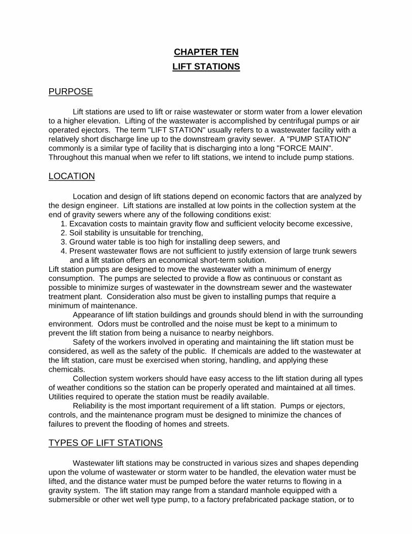
CHAPTER TEN LIFT STATIONS PURPOSE Lift stations are used to lift or raise wastewater or storm water from a lower elevation to a higher elevation. Lifting of the wastewater is accomplished by centrifugal pumps or air operated ejectors. The term "LIFT STATION" usually refers to a wastewater facility with a relatively short discharge line up to the downstream gravity sewer. A "PUMP STATION" commonly is a similar type of facility that is discharging into a long "FORCE MAIN". Throughout this manual when we refer to lift stations, we intend to include pump stations. LOCATION Location and design of lift stations depend on economic factors that are analyzed by the design engineer. Lift stations are installed at low points in the collection system at the end of gravity sewers where any of the following conditions exist: 1. Excavation costs to maintain gravity flow and sufficient velocity become excessive, 2. Soil stability is unsuitable for trenching, 3. Ground water table is too high for installing deep sewers, and 4. Present wastewater flows are not sufficient to justify extension of large trunk sewers
and a lift station offers an economical short-term solution. Lift station pumps are designed to move the wastewater with a minimum of energy consumption. The pumps are selected to provide a flow as continuous or constant as possible to minimize surges of wastewater in the downstream sewer and the wastewater treatment plant. Consideration also must be given to installing pumps that require a minimum of maintenance. Appearance of lift station buildings and grounds should blend in with the surrounding environment. Odors must be controlled and the noise must be kept to a minimum to prevent the lift station from being a nuisance to nearby neighbors. Safety of the workers involved in operating and maintaining the lift station must be considered, as well as the safety of the public. If chemicals are added to the wastewater at the lift station, care must be exercised when storing, handling, and applying these chemicals. Collection system workers should have easy access to the lift station during all types of weather conditions so the station can be properly operated and maintained at all times. Utilities required to operate the station must be readily available. Reliability is the most important requirement of a lift station. Pumps or ejectors, controls, and the maintenance program must be designed to minimize the chances of failures to prevent the flooding of homes and streets. TYPES OF LIFT STATIONS Wastewater lift stations may be constructed in various sizes and shapes depending upon the volume of wastewater or storm water to be handled, the elevation water must be lifted, and the distance water must be pumped before the water returns to flowing in a gravity system. The lift station may range from a standard manhole equipped with a submersible or other wet well type pump, to a factory prefabricated package station, or to
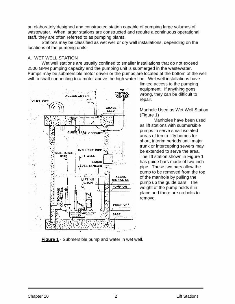
an elaborately designed and constructed station capable of pumping large volumes of wastewater. When larger stations are constructed and require a continuous operational staff, they are often referred to as pumping plants. Stations may be classified as wet well or dry well installations, depending on the locations of the pumping units. A. WET WELL STATION Wet well stations are usually confined to smaller installations that do not exceed 2500 GPM pumping capacity and the pumping unit is submerged in the wastewater. Pumps may be submersible motor driven or the pumps are located at the bottom of the well with a shaft connecting to a motor above the high water line. Wet well installations have
limited access to the pumping equipment. If anything goes wrong, they can be difficult to repair. Manhole Used as Wet Well Station (Figure 1) Manholes have been used as lift stations with submersible pumps to serve small isolated areas of ten to fifty homes for short, interim periods until major trunk or intercepting sewers may be extended to serve the area. The lift station shown in Figure 1 has guide bars made of two-inch pipe. These two bars allow the pump to be removed from the top of the manhole by pulling the pump up the guide bars. The weight of the pump holds it in place and there are no bolts to remove.
Figure 1 - Submersible pump and water in wet well.
Chapter 10 2 Lift Stations
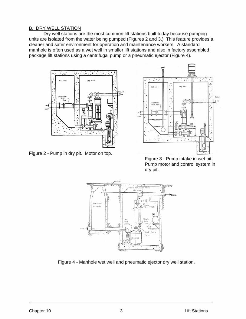
B. DRY WELL STATION Dry well stations are the most common lift stations built today because pumping units are isolated from the water being pumped (Figures 2 and 3.) This feature provides a cleaner and safer environment for operation and maintenance workers. A standard manhole is often used as a wet well in smaller lift stations and also in factory assembled package lift stations using a centrifugal pump or a pneumatic ejector (Figure 4).
Figure 2 - Pump in dry pit. Motor on top. Figure 3 - Pump intake in wet pit.
Pump motor and control system in dry pit.
Figure 4 - Manhole wet well and pneumatic ejector dry well station.
Chapter 10 3 Lift Stations
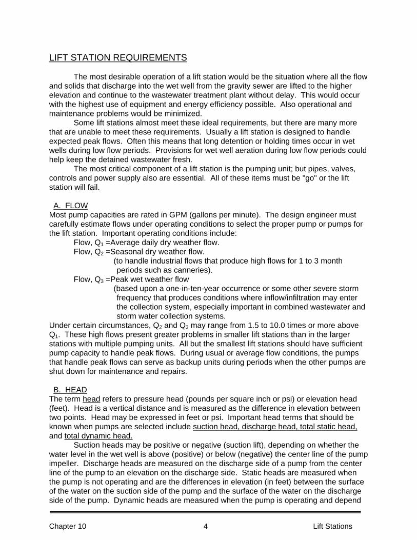
Chapter 10 4 Lift Stations
LIFT STATION REQUIREMENTS The most desirable operation of a lift station would be the situation where all the flow and solids that discharge into the wet well from the gravity sewer are lifted to the higher elevation and continue to the wastewater treatment plant without delay. This would occur with the highest use of equipment and energy efficiency possible. Also operational and maintenance problems would be minimized. Some lift stations almost meet these ideal requirements, but there are many more that are unable to meet these requirements. Usually a lift station is designed to handle expected peak flows. Often this means that long detention or holding times occur in wet wells during low flow periods. Provisions for wet well aeration during low flow periods could help keep the detained wastewater fresh. The most critical component of a lift station is the pumping unit; but pipes, valves, controls and power supply also are essential. All of these items must be "go" or the lift station will fail. A. FLOWMost pump capacities are rated in GPM (gallons per minute). The design engineer must carefully estimate flows under operating conditions to select the proper pump or pumps for the lift station. Important operating conditions include: Flow, Q1 =Average daily dry weather flow. Flow, Q2 =Seasonal dry weather flow. (to handle industrial flows that produce high flows for 1 to 3 month
periods such as canneries). Flow, Q3 =Peak wet weather flow (based upon a one-in-ten-year occurrence or some other severe storm
frequency that produces conditions where inflow/infiltration may enter the collection system, especially important in combined wastewater and storm water collection systems.
Under certain circumstances, Q2 and Q3 may range from 1.5 to 10.0 times or more above Q1. These high flows present greater problems in smaller lift stations than in the larger stations with multiple pumping units. All but the smallest lift stations should have sufficient pump capacity to handle peak flows. During usual or average flow conditions, the pumps that handle peak flows can serve as backup units during periods when the other pumps are shut down for maintenance and repairs. B. HEADThe term head refers to pressure head (pounds per square inch or psi) or elevation head (feet). Head is a vertical distance and is measured as the difference in elevation between two points. Head may be expressed in feet or psi. Important head terms that should be known when pumps are selected include suction head, discharge head, total static head, and total dynamic head. Suction heads may be positive or negative (suction lift), depending on whether the water level in the wet well is above (positive) or below (negative) the center line of the pump impeller. Discharge heads are measured on the discharge side of a pump from the center line of the pump to an elevation on the discharge side. Static heads are measured when the pump is not operating and are the differences in elevation (in feet) between the surface of the water on the suction side of the pump and the surface of the water on the discharge side of the pump. Dynamic heads are measured when the pump is operating and depend
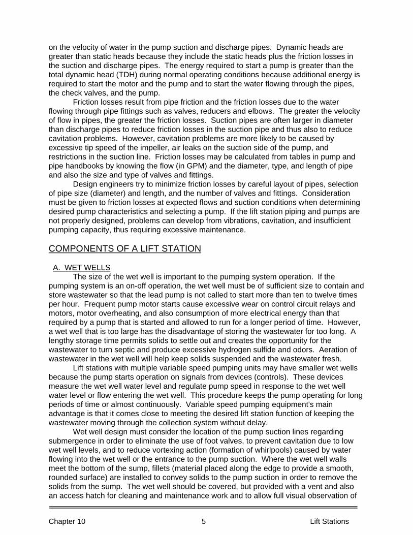
Chapter 10 5 Lift Stations
on the velocity of water in the pump suction and discharge pipes. Dynamic heads are greater than static heads because they include the static heads plus the friction losses in the suction and discharge pipes. The energy required to start a pump is greater than the total dynamic head (TDH) during normal operating conditions because additional energy is required to start the motor and the pump and to start the water flowing through the pipes, the check valves, and the pump. Friction losses result from pipe friction and the friction losses due to the water flowing through pipe fittings such as valves, reducers and elbows. The greater the velocity of flow in pipes, the greater the friction losses. Suction pipes are often larger in diameter than discharge pipes to reduce friction losses in the suction pipe and thus also to reduce cavitation problems. However, cavitation problems are more likely to be caused by excessive tip speed of the impeller, air leaks on the suction side of the pump, and restrictions in the suction line. Friction losses may be calculated from tables in pump and pipe handbooks by knowing the flow (in GPM) and the diameter, type, and length of pipe and also the size and type of valves and fittings. Design engineers try to minimize friction losses by careful layout of pipes, selection of pipe size (diameter) and length, and the number of valves and fittings. Consideration must be given to friction losses at expected flows and suction conditions when determining desired pump characteristics and selecting a pump. If the lift station piping and pumps are not properly designed, problems can develop from vibrations, cavitation, and insufficient pumping capacity, thus requiring excessive maintenance. COMPONENTS OF A LIFT STATION A. WET WELLS The size of the wet well is important to the pumping system operation. If the pumping system is an on-off operation, the wet well must be of sufficient size to contain and store wastewater so that the lead pump is not called to start more than ten to twelve times per hour. Frequent pump motor starts cause excessive wear on control circuit relays and motors, motor overheating, and also consumption of more electrical energy than that required by a pump that is started and allowed to run for a longer period of time. However, a wet well that is too large has the disadvantage of storing the wastewater for too long. A lengthy storage time permits solids to settle out and creates the opportunity for the wastewater to turn septic and produce excessive hydrogen sulfide and odors. Aeration of wastewater in the wet well will help keep solids suspended and the wastewater fresh. Lift stations with multiple variable speed pumping units may have smaller wet wells because the pump starts operation on signals from devices (controls). These devices measure the wet well water level and regulate pump speed in response to the wet well water level or flow entering the wet well. This procedure keeps the pump operating for long periods of time or almost continuously. Variable speed pumping equipment's main advantage is that it comes close to meeting the desired lift station function of keeping the wastewater moving through the collection system without delay. Wet well design must consider the location of the pump suction lines regarding submergence in order to eliminate the use of foot valves, to prevent cavitation due to low wet well levels, and to reduce vortexing action (formation of whirlpools) caused by water flowing into the wet well or the entrance to the pump suction. Where the wet well walls meet the bottom of the sump, fillets (material placed along the edge to provide a smooth, rounded surface) are installed to convey solids to the pump suction in order to remove the solids from the sump. The wet well should be covered, but provided with a vent and also an access hatch for cleaning and maintenance work and to allow full visual observation of
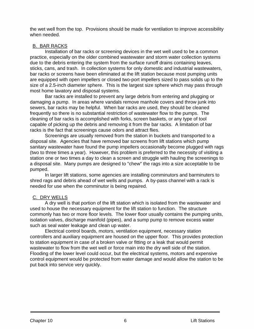
Chapter 10 6 Lift Stations
the wet well from the top. Provisions should be made for ventilation to improve accessibility when needed. B. BAR RACKS Installation of bar racks or screening devices in the wet well used to be a common practice, especially on the older combined wastewater and storm water collection systems due to the debris entering the system from the surface runoff drains containing leaves, sticks, cans, and trash. In collection systems for only domestic and industrial wastewaters, bar racks or screens have been eliminated at the lift station because most pumping units are equipped with open impellers or closed two-port impellers sized to pass solids up to the size of a 2.5-inch diameter sphere. This is the largest size sphere which may pass through most home lavatory and disposal systems. Bar racks are installed to prevent any large debris from entering and plugging or damaging a pump. In areas where vandals remove manhole covers and throw junk into sewers, bar racks may be helpful. When bar racks are used, they should be cleaned frequently so there is no substantial restriction of wastewater flow to the pumps. The cleaning of bar racks is accomplished with forks, screen baskets, or any type of tool capable of picking up the debris and removing it from the bar racks. A limitation of bar racks is the fact that screenings cause odors and attract flies. Screenings are usually removed from the station in buckets and transported to a disposal site. Agencies that have removed bar screens from lift stations which pump sanitary wastewater have found the pump impellers occasionally become plugged with rags (two to three times a year). However, this problem is preferred to the necessity of visiting a station one or two times a day to clean a screen and struggle with hauling the screenings to a disposal site. Many pumps are designed to "chew" the rags into a size acceptable to be pumped. In larger lift stations, some agencies are installing comminutors and barminuters to shred rags and debris ahead of wet wells and pumps. A by-pass channel with a rack is needed for use when the comminutor is being repaired. C. DRY WELLS A dry well is that portion of the lift station which is isolated from the wastewater and used to house the necessary equipment for the lift station to function. The structure commonly has two or more floor levels. The lower floor usually contains the pumping units, isolation valves, discharge manifold (pipes), and a sump pump to remove excess water such as seal water leakage and clean up water. Electrical control boards, motors, ventilation equipment, necessary station controllers and auxiliary equipment are housed on the upper floor. This provides protection to station equipment in case of a broken valve or fitting or a leak that would permit wastewater to flow from the wet well or force main into the dry well side of the station. Flooding of the lower level could occur, but the electrical systems, motors and expensive control equipment would be protected from water damage and would allow the station to be put back into service very quickly.
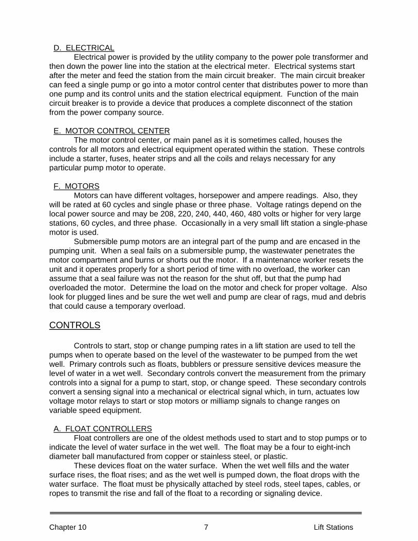
Chapter 10 7 Lift Stations
D. ELECTRICAL Electrical power is provided by the utility company to the power pole transformer and then down the power line into the station at the electrical meter. Electrical systems start after the meter and feed the station from the main circuit breaker. The main circuit breaker can feed a single pump or go into a motor control center that distributes power to more than one pump and its control units and the station electrical equipment. Function of the main circuit breaker is to provide a device that produces a complete disconnect of the station from the power company source. E. MOTOR CONTROL CENTER The motor control center, or main panel as it is sometimes called, houses the controls for all motors and electrical equipment operated within the station. These controls include a starter, fuses, heater strips and all the coils and relays necessary for any particular pump motor to operate. F. MOTORS Motors can have different voltages, horsepower and ampere readings. Also, they will be rated at 60 cycles and single phase or three phase. Voltage ratings depend on the local power source and may be 208, 220, 240, 440, 460, 480 volts or higher for very large stations, 60 cycles, and three phase. Occasionally in a very small lift station a single-phase motor is used. Submersible pump motors are an integral part of the pump and are encased in the pumping unit. When a seal fails on a submersible pump, the wastewater penetrates the motor compartment and burns or shorts out the motor. If a maintenance worker resets the unit and it operates properly for a short period of time with no overload, the worker can assume that a seal failure was not the reason for the shut off, but that the pump had overloaded the motor. Determine the load on the motor and check for proper voltage. Also look for plugged lines and be sure the wet well and pump are clear of rags, mud and debris that could cause a temporary overload. CONTROLS Controls to start, stop or change pumping rates in a lift station are used to tell the pumps when to operate based on the level of the wastewater to be pumped from the wet well. Primary controls such as floats, bubblers or pressure sensitive devices measure the level of water in a wet well. Secondary controls convert the measurement from the primary controls into a signal for a pump to start, stop, or change speed. These secondary controls convert a sensing signal into a mechanical or electrical signal which, in turn, actuates low voltage motor relays to start or stop motors or milliamp signals to change ranges on variable speed equipment. A. FLOAT CONTROLLERS Float controllers are one of the oldest methods used to start and to stop pumps or to indicate the level of water surface in the wet well. The float may be a four to eight-inch diameter ball manufactured from copper or stainless steel, or plastic. These devices float on the water surface. When the wet well fills and the water surface rises, the float rises; and as the wet well is pumped down, the float drops with the water surface. The float must be physically attached by steel rods, steel tapes, cables, or ropes to transmit the rise and fall of the float to a recording or signaling device.
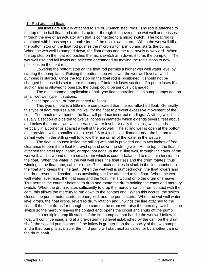
Chapter 10 8 Lift Stations
1. Rod attached floats Ball floats are usually attached to 1/4 or 3/8-inch steel rods. The rod is attached to the top of the ball float and extends up to or through the cover of the wet well and passes through the eye of an actuator arm that is connected to a micro switch. The float rod is equipped with brass stops on both sides of the micro switch arm. When the wet well fills, the bottom stop on the float rod pushes the micro switch arm up and starts the pump. When the wet well is pumped down, the float drops and the rod travels downward. When the top stop on the float rod pushes the micro switch arm down, it turns the pump off. The wet well rise and fall levels are selected or changed by moving the rod's stops to new positions on the float rod. Lowering the bottom stop on the float rod permits a higher wet well water level by starting the pump later. Raising the bottom stop will lower the wet well level at which pumping is started. Once the top stop on the float rod is positioned, it should not be changed because it is set to turn the pump off before it loses suction. If a pump loses it's suction and is allowed to operate, the pump could be seriously damaged. The most common application of ball type float controllers is on sump pumps and on small wet well type lift stations. 2. Steel tape, cable, or rope attached to floats This type of float is a little more complicated than the rod-attached float. Generally this type of float requires a stilling well for the float to prevent excessive movement of the float. Too much movement of the float will produce incorrect readings. A stilling well is usually a section of pipe ten to twelve inches in diameter which extends several feet above and below the normal wet well operating water level. Usually the stilling well stands vertically in a corner or against a wall of the wet well. The stilling well is open at the bottom or is provided with a smaller inlet pipe of 2.5 to 4 inches in diameter near the bottom to permit water in the stilling well to follow the rise or fall of the water in the wet well. The float is housed inside the stilling well and is provided one to two inches of free clearance to permit the float to travel up and down the stilling well. At the top of the float is attached the steel tape, cable, or rope that goes up the stilling well, through the cover of the wet well, and is wound onto a small drum which is counterbalanced to maintain tension on the float. When the water in the wet well rises, the float rises and the drum rotates, thus winding in the float tape, cable or rope. This rotation takes in slack in the line attached to the float and keeps the line taut. When the wet well is pumped down, the float lowers and the drum reverses direction, thus unwinding the line attached to the float. When the wet well water level rises, the float rises and the float line is wound onto the drum or sheave. This permits the counter balance to drop and rotate the drum holding the cams and mercury switch. When the drum rotates sufficiently to drop the mercury switch from contact with the cam, this allows the mercury to run down to the contact end. When this occurs, the switch closes, the pump motor starter is energized, and the pump starts. When the wet well water level drops, the float drops, reverses drum rotation and unwinds the line attached to the float. If the float drops far enough, the cam on the drum will raise the mercury switch, tilt the switch so the mercury leaves the contact end, opens the circuit and shuts off the pump. In a multiple pump lift station, if the first pump cannot handle the wet well inflow, the float will continue rising and at a pre-determined level established by the cam on the drum shaft, the second pump starts. If the inflow is greater than the capacity of the two pumps and a third pump is available, the third pump will start next as called for by another cam on the drum shaft.
Chapter 10 9 Lift Stations
After all pumps available are running and the wet well level continues to rise, the last position on the cam often is used to transmit an alarm signal that the wet well is flooded or will be flooded soon. Float controllers are used today for many applications due to their economical cost and ease of maintenance. The floats also provide flexibility by allowing the lift station operator to change lead pumps and pump start-up sequences in a multiple pump station every week or month or on some other pre-scheduled frequency. This procedure distributes wear fairly equally on all equipment by a single pump control circuit plug being moved from cam to cam output. Also this procedure could be adjusted so all of the pumping equipment will not wear out at once. Limitations of float control systems include the following: 1. Grease and debris enter the stilling well and hinder or stop the up-and-down movement
of the float. Debris can be removed from the top of the stilling well. Grease can be controlled by running clear water (hot water is better than cold water) into the stilling well at a rate of 1 to 2 gallons per minute to keep the float and stilling well clear of grease and solids. Be sure that this flow of water does not produce false readings of the wet well level unless the stilling well openings to the wet well become plugged.
2. Float attachment line or counterbalance line breaks and unwinds from drum sheave, thus allowing counterbalance to fall and all or none of the pumps could be called on to operate.
3. Floats develop leaks which change or stop pump operation. 4. Cables or ribbons attached to float can become twisted. B. ELECTRODE CONTROLLERS Use of this method of control requires that electrodes be installed and maintained in compliance with safety regulations. The water level sensing or detecting device is simply a weighted electric lead or electrode hanging in the wet well at staggered elevations, usually six to eight inches apart. As the wet well water level rises and submerges an electrode, the water surrounding the electrode completes the control circuit and starts the pump. When the wet well level is pumped down and the electrode exposed to air, it opens the electrical circuit and shuts off the pump. One electrode controls a single pump, and each pump usually has its own electrode. A high wet well elevation electrode is used to indicate flooding of the wet well and activates an alarm to signal a high water level or flooding. Limitations of electrode controllers include the following: 1. Rags and debris can wrap around electrodes and alter desired start and stop water
levels and sequences of pumps. 2. Grease and/or slime can cover an electrode, thus preventing good conductivity and
causing intermittent or unreliable operation. Enclosed electrode controllers (Seal-trode units) are a refinement of the old free floating electrodes. They work in the same manner except they are enclosed in a two to three-inch diameter pipe with a bulb-type container on the bottom end containing an electrolyte solution. Electrodes (one for each pump and a high level alarm) are set at different elevations in the pipe housing. The bulb at the end of the pipe holds from three to eight quarts of electrolyte solution. This volume is sufficient so that water pressure on the outside of the bulb will force the electrolyte solution up the tube to an electrode that completes the circuit and turns on the pump. As the water level in the wet well rises, it compresses the bulb and forces the electrolyte up the pipe to the electrode.
Chapter 10 10 Lift Stations
When the wet well level is high enough to develop the pressure required to force the electrolyte solution up the tube to the electrode, the circuit is completed and the pump is started. When the water level in the wet well drops, the electrolyte solution also falls and opens the circuit. The electrodes in this system are spaced much closer in elevation (1.5 to 2.0 inches) because the change in water pressure on the bulb is small compared to changes in water depth in the wet well. Limitations of enclosed electrode controllers include the following: 1. When bulb breaks, electrolyte solution is lost. 2. Shorts occur in electrode wiring. 3. Bulb life is three to five years. C. PRESSURE SENSING CONTROLLERS (AIR BUBBLERS) Air sensing (pneumatic) controllers are being used in many new lift stations being constructed today. They are adaptable to several different control systems and may be used in either simple diaphragm and mercury switches for control inputs, in complex fluidics (air) systems using orifices and chambers to control outputs, or in analog equipment with differential transmitter square root extraction (a method of measuring pressure) and averaging relays that convert signals from pneumatic to electronic (4 to 20 milliamp) outputs for use by controllers and integrators. Regardless of which control system is used, the initial sensing or depth measuring device is similar. A compressed air supply is used to sense water depth, a rotometer is used to measure air flow rates, a 3/8 to 1/2-inch sensing line runs into the wet well, and a device is necessary to determine back pressure on the air sensing A continuous air flow is essential, but a large flow of air is not necessary. Air flows through the wet well bubbler line at a constant flow rate of one to eight standard cubic feet of air per hour (SCFH). At low water level elevations in the wet well, little air pressure is required to overcome the weight of water over the open end of the bubbler line. As the wet well level rises, more air pressure is required to overcome the water pressure. For every foot of water rise in the wet well, the bubbler system will require an additional 0.433 psi of air pressure on the air line to overcome the water pressure. The pressure sensing device on the air bubbler supply line senses the back pressure and at predetermined set points of pressures, will start, speed up, or stop the pumps or equipment as required. There are many manufacturers and instrumentation companies who use pneumatic systems for control, and their O & M manuals should be consulted for your type of equipment and application. Limitations of pressure differential controllers include the following: 1. Air compressor failure. 2. Bubbler blockage (line must be purged regularly), tube breakage, or outlet elevation
shifts. 3. Complex equipment provides more opportunity for failures and requires a higher level
of training for workers to troubleshoot, repair and keep instruments calibrated. Often the more reliable an alarm system is, the more complex it becomes and thus the more difficult to maintain because of backup systems.
Chapter 10 11 Lift Stations
PUMPS Most lift station pumps are single stage (one impeller) centrifugal pumps of the open impeller or closed two port non-clog design with minimum size sphere passage size of 2.5 inches, but preferably larger. Each lift station should be equipped with at least two pumps to provide continuous operation if one pump fails or requires repairs. The pumps should be capable of being rotated as the lead pump (the pump to start first) so that equal wear may be distributed to the pumping equipment by weekly or monthly rotation of the lead pump. Some pumps have electronic controls that automatically alternate the lead pump with each start. Each pump must be equipped with a suction and discharge isolation valve so that the pump can be isolated from the wet well or the discharge force main for draining, cleaning, repacking, and other maintenance work. The isolation valves should be gate valves. If plug valves are used in this application, problems can develop, particularly if the plug valves are not slow-closing hydraulic or pneumatic controlled valves, and the discharge head of the pumping system is above 150 feet (69 psi). Under these conditions, the discharge check valve can become blocked with rags and debris, it will not close, and the discharge line or force main will drain back through the system to the wet well. When you start to close the valve, wastewater flow will slam the plug valve shut and possibly injure you and break the valve body or a portion of the pipe system from the water hammer due to the sudden stoppage of the flowing water. To avoid these problems, shut valves very slowly. Large plug valves should have gear operators so they cannot be slammed. Plug valves are rarely used in discharge lines because they do not provide a full opening. This restriction can become clogged with rags or sticks. If high discharge heads occur, slow-closing butterfly or plug valves operated by hydraulic or pneumatic systems are used to prevent the check valve from slamming shut and causing water hammer. For example, if a discharge line has a pressure of 75 psi and the discharge valve is closed suddenly, the shock wave (water hammer) can create pressures over 300 psi in the pipe, thus possibly bursting the discharge line and flooding the station. Excessive water hammer pressures can be avoided if the valve closing times are more than 30 seconds; however, the closing time should be less than two minutes. Each pump should be equipped with a bottom volute drain valve and line to the sump and a top or middle volute access inspection port for cleaning the pump. Large horizontal pumps should have a vent valve on top of the volute for priming purposes. Seal water piping should be accessible; and if from a domestic water supply, an air gap system must be used to prevent contamination of the water that serves the public or operation and maintenance workers. Some pumps have grease seals instead of water seals to avoid the problems of having to protect a drinking water supply. The pump should be equipped with wearing rings and have provisions for inserting or removing shims in order to move the shaft to obtain proper clearance between the wearing rings and the impeller. SUMP PUMP The lower floor of the dry well should be provided with a sump and submersible pump to collect seal water and water used to hose down and clean up the area. This drainage water should be pumped out of the dry well sump and discharged at a high elevation into the wet well.
Chapter 10 12 Lift Stations
VENTILATION AND AUXILIARY EQUIPMENT The dry well must be equipped with ventilation equipment to maintain the dry well portion of the station atmosphere in a dry and safe environment. Ventilation equipment should operate continuously to assure a safe working access for operation and maintenance workers. A lift station dry well is considered a confined space by state industrial safety agencies and requires frequent air changes. Monitor for oxygen deficiency and explosive and toxic gases during visits to the station. Wet wells also require provisions for ventilation. Dehumidifiers may be necessary to keep condensation under control. This problem is most serious in the smaller, package-type lift stations which are of prefabricated steel. Usually the dehumidifier runs constantly, and outside air is used for ventilation only when the access cover is open. A ventilation fan can be turned on or off by a switch at the access cover. This procedure keeps moist, outside air from entering a lift station when it is unoccupied and provides the driest possible conditions. Auxiliary power should be provided for lift stations. Critical lift stations that must be pumped often to prevent flooding may be equipped with emergency generator units that are automatically started during electrical power failures. Portable generators are often used when it is acceptable for longer periods between pumping. In some cases, portable gas powered pumps may be used until normal electrical power is restored. THE NEWLY CONSTRUCTED LIFT STATION Many large municipal agencies do their own design work for lift stations. Smaller agencies usually rely upon a consulting engineering firm for station design. In either case, operation and maintenance workers should be given the opportunity to review the prints and specifications of a new lift station before the award of a contract for construction. This review is very important to be sure adequate provisions have been made for the station to be easily and properly operated and maintained. EXAMINATION OF PRINTS When examining the prints, operation and maintenance workers should look for accessibility not only for equipment, but for workers to get to the station. Is there sufficient space for vehicles to park and not restrict vehicles passing on streets or pedestrians on sidewalks? Is there room to use hydrolifts, cranes and high velocity cleaners as needed at the lift station? Are overhead clearances of power lines, trees and roofs adequate for a crane to remove large equipment? Is there sufficient room to set up portable pumping units or other necessary equipment in cases of major station failures or disasters? Are station doors and access hatches large enough to remove the largest piece of equipment? Are lifting hooks or overhead rails available where needed in the structure? Has sufficient overhead and work room been provided around equipment and control panels to work safely? Is lighting inside and outside the station provided and is it adequate? Does the alarm system signal high water levels in the wet well and water on the floor of the dry well? Is there sufficient fresh water at a high enough pressure to adequately wash down the wet well? Are there any man traps or head knockers such a low hanging projections or pipes, unprotected holes, or unsafe stairs or platforms? Is there access to the wet well? If you have to clean out incoming lines, it may be necessary to put a temporary pump in the wet well. All of these questions must be answered satisfactorily if the lift station is to be easily operated and maintained.

Chapter 10 13 Lift Stations
Equipment should be laid out orderly with sufficient work room and access to valves and other station equipment, controls, wiring, pipes and valves. If there is any possibility of future growth and the station may be enlarged, be sure provisions are made to allow for pumping units to be changed or for the installation of additional pumping units. If additional pumping units will be necessary, be sure spools and valves are built now for ease of expansion. Be sure there is sufficient room to add electrical switch gear for future units. If stationary standby power units are not provided, make certain there are external connections and transfer switches for a portable generator. READING SPECIFICATIONS Review the specifications for the acceptability of the equipment, piping, electrical system, instrumentation, and auxiliary equipment. Determine if the equipment is familiar to your agency and if its reliability has been proven. Find out what warranties, guarantees, and operation and maintenance aids will be provided with the equipment and the lift station. Require a list of names, addresses and phone numbers of persons to contact in case help is needed regarding supplies or equipment during start up and shake down runs. Be sure that the equipment brochures and other information apply to the equipment supplied. Sometimes new models are installed and you are provided with old brochures. Be sure the painting, color coding on pipes and electrical circuits meet with your agency's practice. Try to standardize electrical equipment and components as much as possible so one manufacturer can't blame the other when problems develop. Standardization also can help to reduce the inventory of spare parts necessary for replacement. A few hours spent reviewing plans and specifications will save many days of hard and discouraging labor in the field in the future when it is a major job to make a change. Very often changes on paper are relatively simple. PRELIMINARY INVESTIGATION OF A NEW LIFT STATION After a lift station has been constructed, it is inspected by the contractor, the engineer, and the operating agency before final acceptance. This inspection should be planned and conducted by the people responsible for the operation and maintenance of the lift station in cooperation with the contractor and the engineer. One way to accomplish this is to include in the specifications a specific schedule that identifies the section of specification, the item to be checked and who is responsible; for example, electrical contractor, mechanical contractor, or other specific contractor. Then check off each item by noting who accepted each item and the date. All equipment checkout and adjustments should be performed PRIOR to any equipment training as this will maximize the amount of time spent on training as opposed to adjustment and troubleshooting. Documentation is particularly important for proper operation and maintenance of the lift station equipment. The equipment manufacturers' O & M manuals should include the following: 1. A suitable binder that allows for quick and easy reference to all mechanical/electrical
and hydraulic equipment provided in the pump station. generally, xerox copies should not be accepted, since they may be illegible, and therefore, of limited value to the operator.
Chapter 10 14 Lift Stations
2. Information about each piece of electrical and mechanical equipment should include nameplate data, operation and maintenance instructions, spare parts list, recommended spare parts stock list, part numbers, troubleshooting information, assembly/disassembly instructions, tolerances, tools required, and safety precautions. In other words, a sufficient amount of information to allow adequate maintenance of the equipment.
3. The manual should be available when you accept the station from the contractor, not three months later.
Now, during the preliminary inspection, is the appropriate time to develop and record both routine and emergency information and procedures. Use the following outline as a guide in assembling your documentation. 1. As-built specification of the facility including: a. Size, length and details of force main (discharge point). b. Available power and fuse size. c. Pump and motor sizes and rated capacities. d. Actual capacities of pumps and rates of flow throughout the day. e. Normal pump levels-start/stop/high and low levels. 2. Elevation of each manhole invert and depth of the manhole. 3. Lowest homes on the system (most probable backup points). 4. Alternate route of temporary pumping: a. Elevation and length of temporary pumping. b. Type of equipment needed. 5. Number of services, plus commercial hookups. 6. Available equipment and methods of operating station when a power outage
occurs. 7. Equipment needed for pump and motor removal. 8. List of private companies providing emergency pumping equipment and
personnel. 9. Station data: a. Wet well size. b. Storage time, average flow. c. Average flow, GPM. d. Peak flow, GPM. e. Average flow, GPD. f. Wet well depth. g. Distance of bubbler tube off wet well bottom. h. Type of wet well suction. PUMP STATION CALIBRATION As part of the startup and acceptance procedure, a pump station calibration should be performed to: 1. Verify operating conditions of the pumps in accordance with the nameplate, and; 2. Establish a base line that can be used for comparison when future pump station
calibrations are performed. The calibration of pump station is a fairly quick and easy method to verify the operating efficiency of the pumps including capacities and discharge heads.
Chapter 10 15 Lift Stations
Operation under test conditions will reveal only the immediate equipment and construction problems. These problems should be recorded on a punch list during the preliminary inspections and a copy given to the contractor. This punch list of problems should be quickly corrected so the station can be ready for service. Do not accept any portion of a new lift station, because official acceptance of completed work is the engineer's job. To obtain maximum life and use from a new lift station, begin the station preventive maintenance program now when it is new. Start the program by filing data in a station record book. Record station identification code number, location by map and street numbers, date of construction, size of station by flow capacity and other important information required by your agency. Also file a set of plans and specifications for reference purposes. Start the preventive maintenance program by making a complete list of all equipment at the station. Information recorded should include equipment name plate data. Mark each piece of equipment with an identification code number and record the number. There should be a minimum of two copies of this information. Keep one copy at the lift station and the other in the station record book at the agency office. Once this has been done, permanent identification of all equipment involved in the station will be available when needed. Prepare a spare parts list and order any extra parts now. Record keeping must begin when the station is first started so that any peculiarities of the equipment are known from the beginning. These records should include any of the contractor's data collected during construction and also data required according to the specifications. These specifications include:
1. Equipment manufacturers' O & M manuals. 2. Engineers O & M instructions, including detailed emergency procedures. 3. Pump and motor operational characteristics. 4. Pump and motor coupling alignment readings. 5. Wet well control levels. 6. Auxiliary equipment data.
INSPECTION OF LIFT STATION Hopefully you had the opportunity to review the plans and specifications for the new lift station. Now is the time to determine if the station was built as you wished. Look at those items you previously reviewed. Ask yourself what problems will be faced when maintenance and repairs are to be carried out under adverse conditions. Think of the worst situations so that your preparations will be adequate when needed. Inspect the building for access so equipment can be removed. To insure that equipment can be worked on, the following items must be considered. Is there an emergency lighting system and is it adequate? Is there enough head room to pull pumps, motors, gear heads or other pieces of equipment? If head room is not needed, are the passageways wide enough to allow for the removal of gear boxes, engines, control panels, and standby generators? If pumps have to be removed through the roof of a building, do we have clearance for a crane or other lifting device to get within reaching distance? Where are the electrical lines located that supply the building? Will they restrict use of the lifting equipment? The time to consider all of the above is now, not when conditions are adverse. If there are potential problems related to equipment removal, the time to correct these problems is now. Plan to conduct corrective work before a crisis occurs. Don't wait for an emergency to arise to discover that a critical piece of equipment can't be moved when a unit needs repair. Dismantling equipment in place under restrictive conditions is
Chapter 10 16 Lift Stations
slow and difficult work. The next unit to inspect is the wet well. What kind of conditions will be encountered when you attempt to clean the sump or possibly to enter it and remove grit? In a sanitary wet well, are there enough openings for washing the sump walls and floor? Can it be ventilated easily? What type and size of ladder will you need for access? If there is a bar rack, or comminuting device, consider the conditions you will encounter to clean the rack and how you will dispose of the debris. Also consider the tools needed and whether or not the necessary tools will be stored at the site. If tools must be transported, make notes of what will be needed and how transportation will be accomplished. Inspect the equipment that measures the water level in the wet well. Before entering any lift station or other wastewater facility, safety procedures must be followed to insure that the hazards encountered will be eliminated or brought to a minimum. The hazards are as follows: 1. Insufficient oxygen. 2. Explosive and toxic gases. 3. Poor footing caused by grease or slime. 4. Unsafe stairs and walkways. 5. Dangerous electrical gear. 6. Inadequate drainage. If the wet well is to be entered, begin by setting up a blower that will give a minimum of two air changes a minute within the wet well. The wet well must be washed thoroughly using a hose with a nozzle. After washing has been completed, the wet well can be monitored for toxic or poisonous gases, explosive gases, and lack of oxygen. If all conditions are satisfactory, then and only then is it permissible to enter the wet well. All of the safety equipment and clothing listed under safety for confined spaces should be available for use at this time. Monitor the wet well gases and oxygen continuously until the job is completed and everyone is out of the sump. The next item to inspect is the electrical equipment. Begin by recording all name plate data. Put code numbers on each panel beginning at the main breaker. Branch panels that supply power to major circuits carry the code number of the piece of equipment that it serves. A lighting branch panel has its own listing or numbers and the lights or plugs it serves also carry this number. With a system like this, the problem of locating controls, plugs, and lights is quite simple. Individual inspection of the major circuits is necessary. Record the parts that most likely will need attention during an emergency. All fuses must be listed and spares kept at the station. Data on switches, relays and heater strips must be recorded. Be sure that all overload heaters are the proper size. Control circuit equipment must be listed. Identify all related equipment with proper code number. Make this inspection with the main breaker to the equipment being inspected locked in the OFF position. No attempt should be made to inspect or repair electrical equipment unless a basic knowledge of electricity and the safety precautions needed are fully understood and applied. Request an electrician to help if you are not qualified or not authorized to inspect electrical equipment, circuits and controls.
Chapter 10 17 Lift Stations
After listing all necessary data and putting code numbers in place, read the operating instructions and examine the controls for their proper operation. Move all switches with the power off to see how they operate. Check reset buttons and know what they are supposed to do. Before the station becomes operational, it is essential to learn how things are supposed to work. The approach to solving any problem must be made with logic and caution. Be deliberate and think each step out before making any changes. Mark all settings, if possible, so that you can return to the starting point. Wait a short period when changing settlings to obtain and observe the results. Do not make a change if you think it is not safe. Before leaving the electrical equipment, tag any dangerous area with "not to be tampered with or touched by inexperienced hands" and lock out. The next point of inspection is the pumps. All name plate data must be recorded. Lock out pump and determine direction of rotation. If local electrical utility company has worked on their lines near the station, be sure the power leads (legs) are hooked up correctly and the rotation of the pumps is in the proper direction. Inspect the backspin preventer if the pumps are so equipped by trying to turn the pump shaft in the direction against the indicated rotation. Backspin equipment operation also may be detected by listening to the pump motor when the unit is shut down after a run. When the unit comes to a stop, the backspin unit begins to engage and it can be heard as a ratcheting sound. If a right angle gear head is used, the backspin equipment may be located on this unit. Equipment specifications will have to be checked to determine if there is anti-rotation equipment provided in the gear head. Examine all gages for location and determine at this time what they are to indicate. Any valves located on the suction or discharge should be opened and closed to examine for correct and easy operation so that you are familiar with them. Place equipment numbers on these valves so that a preventive maintenance card can be made to service them. Maintenance record cards should be prepared for each piece of equipment inspected. Inspect the drive and pump for proper alignment. If belt driven, record the sizes of the belts and numbers so that spares will be available when needed. Inspect all rotating parts to be sure all guards are in place and secure. The guards must be built for easy access to the equipment being shielded, but still meet all safety requirements. Inspect the lubrication equipment used and note all pertinent information needed to keep it operating. Solenoids used to operate the oilers should be standardized when reviewing the specifications in order to reduce the inventory of spares necessary for replacement. Inspect suction and discharge lines. The suction line must be kept clear of debris. If a check valve is supplied on the pump discharge pipe, this valve can become a problem when stringy material gets caught on the flapper and it stays in the open position. If the lift station uses gasoline or diesel engines, they may be in the form of stand-by generators or as a pump drive. When used as a pump drive, the operation may go through a right angle gear unit. These units are used to keep a large engine from being located on a lower deck where the pump must be located for efficient operation. The engine is kept on the top floor for easy access, cooling, ventilation, exhaust, and above the level of flooding. There will be very few problems with the right angle gear if the proper design unit is used for a given job. The most important point is to have the proper lubrication for the gears. Preventive maintenance will maintain the unit free of leaks. Cooling is supplied to some units, but only when the gear head is to run continuously for a long period of time. You must inspect the drive shaft and its universal joints. Lubrication is necessary, but should be kept to a minimum because too much will rupture the seal on the universal and cause failure by allowing the entrance of foreign material.
Chapter 10 18 Lift Stations
The engine must be inspected for sufficient oil, water and fuel to operate properly. Without any of these, the unit will not function properly. Examine the battery for water, tight cables and clean terminals. If the engine is large and requires compressed air for starting, inspect the auxiliary air system. Inspect and adjust alarm system for proper operation at the predetermined points of alarm or shut down. Failure of the alarm system or shut down devices could cause an engine to burn up. Make sure that all hoses are secure and clamped tight. Loose nuts and bolts must be tightened. Be aware of the ones that continually become loose. A different type of fastener may solve this problem. Leakage of any sort should not be tolerated. Keep cleaning equipment at the station to keep leaks wiped up so that you know when a new leak starts. Vibration will continually cause problems of leakage and loose parts, so you must never let up on your preventive maintenance program. If there is a clutch to disengage the engine from the drive shaft, test its operation. It should be a little hard to engage and disengage because the unit must snap over center when operated. Lubrication of the clutch throw-out bearing should not be excessive because the friction plates will fail if contaminated with grease. The engine should be maintained as you maintain your automobile engine. Change the oil on a regular schedule to remove contamination from the engine's inner parts. Inspect the oil for metal filings and sludge when changing the oil to stay aware of the engine condition. If filings are noted, a failure of bearings may be assumed. Look for water or an oil-water emulsion that indicates water in the wrong place. If a qualified lab is available, oil may be tested to determine when a change is necessary. Sludge indicates that excessive dirt or carbon have found their way into the crankcase. This may be a failure of the engine's breathing system or just plain blow-by at the rings. Engines should be run from two to four hours during extensive test runs to permit complete heating of all parts and to observe performance during continuous operation. Inspect the engines' heating and cooling systems. Short runs of 5 to 15 minutes should be avoided (especially with large engines) because this is when the most damage can be done to a cold or not properly heated engine. If the engines are not being used, they should be test run monthly for four hours carrying a typical load. Determine what type of fuel is to be used and the storage capacity, the engine's consumption rate, and when the fuel will be delivered. The fuel tank should be kept full so condensation won't collect on top of the tank. Inspect all controls for free and easy operation. Make a record of their settings before and after operation. This becomes the standard and a starting point for trouble shooting when problems occur in the future. When operating, set marks can be made with fingernail polish at the set point. The question may arise at this point as to why bother to check everything on the engine so thoroughly? Inspecting and obtaining a standard for the engine will help tremendously when problems do occur. The jobs of trouble shooting and repairing become easy when there is good data for reference. This data can be obtained only when the engine is new or rebuilt and is being operated for the first time. The final point of inspection is the housekeeping needed to maintain an acceptable station which will satisfy the public or surrounding area. Inspect all fences to see that they are complete and have a neat appearance. If made of wood, be sure the paint has good color and is protecting the wood. Chain link fences usually require little maintenance, but should still be inspected for damage or poor installation.
Chapter 10 19 Lift Stations
Metal chain link fences must be grounded in case a power line drops across them and an unsuspecting worker goes to open the gate. Examine all paved areas for proper drainage and good workmanship when an area is paved. Inspect unpaved areas for weed control. Examine all exterior parts of buildings. Look for poor installation or possible future problem areas. At this time, get a ladder and inspect the building's roof. Be sure that all openings are adequately covered or louvered. OPERATIONAL INSPECTION We are now ready to operate the lift station. Open any valves on the influent line to fill the wet well. Make certain that the pump volute drain lines and vent lines are closed. If there is no wet well, open the valve to the suction side of the pump. Inspect the sump and bar rack at this point for debris and free flow into the station. Remove the floating debris left by the contractor in the sump or off the bar rack that you should have removed BEFORE the station is placed in service. Problem materials include small pieces of wood, like grade stakes or pieces of plastic of any size, cans, and bottles. Some objects can plug off the eye of the impeller. With the sump filling, inspect your sump level indicator to see that it is working properly. If there is no indicator, visually check the sump level or watch the rise in the pump control stilling well. If a bubbler system is used, watch the pressure gage indicator and verify wet well level readings with actual readings. Once the station is in operation, the determination of the sump level will become a part of the normal inspection for system maintenance. Inspect the discharge side of the pump for clear passage of the liquid to be pumped. All valves must be open. Bleed air from volute of pump. Sumps usually fill slowly unless a means of causing rapid filling can be found, such as using water from a fire hydrant. When the sump is filling, recheck for power to pump and proper rotation of the pump. If an engine is the power source, it must be checked out before operating. Put the pump on manual operation and momentarily start pump. Watch rotation of pump shaft to see that rotation is correct. There is usually an arrow attached to the side of the pump to indicate the proper direction. If there is rot, you will have to refer to the manufacturer's manual to find out how to determine correct rotation. Another means of determining rotation is to take a load check of the amperage drawn by the pump motor and compare this value with motor name plate data. If the rotation is in the wrong direction, the amp reading will be lower than the motor rating due to less work being done by the pump by rotating backwards. Lower amp readings also can result from head conditions lower than design head conditions. If the discharge flow is low or the wet well is being drawn down slowly, the rotation could be in the wrong direction. Now that the rotation is in the proper direction, the next job is to see that all operating controls are put into the automatic position for the test operation. Start by examining all automatic switches to see that they have been put into the automatic position. Circuit breakers must be checked to see that they are in the on position. Oilers or solenoids operating the oilers should have been inspected during previous inspections. The electrical alarm systems must be examined to see that they are in the activated position. The electrical components of an engine must be inspected to be sure that there are no drains on the battery. The mechanical inspections should include inspecting all valves to see that they are open or closed according to the operation desired. You must be sure that all oilers have been filled and are not dripping.
Chapter 10 20 Lift Stations
If a bubbler system is used, an inspection should be made to determine that it is functioning properly and that there is enough air pressure provided to make the control system operate. Other mechanical checks should be made on the engine. Determine that the linkage is ready to operate. Inspect the clutch to be sure that it is engaged. Examine all cooling water valves to see that they are in the proper position. Check to see that pre-heaters (if provided) on the engine are operating. The heaters inside the building should be examined to see that they are functioning to maintain the proper humidity and temperature within the station. Up to this point we have been recording all the data that have been observed. This information becomes your base for future operation reference. Notify operators of downstream lift stations and wastewater treatment plants that the lift station is being tested and tell them the volumes of water that can be expected. Allow the sump to fill and activate the station. Watch the level of water in the sump to be sure that the pump starts at the desired level. If not, adjust this operating point by whatever means are available. The pump must be stopped after being started so as not to pull the sump level down too far. When the starting point has been set by a visual or simulated means, we can continue to the next point of operation and that is to allow the sump to continue to rise. If more than one pump is involved, each start position for each pump must be determined and recorded as the level rises until all start points have been activated. Allow the level to rise and activate the high level alarm. At this point you may now start the pumps in their reverse order. Each pump when started must be inspected for its operation and all data recorded. The first item to inspect is the electrical load on motors. Record any electrical malfunctions and have them corrected. The pump should be inspected for proper operation and any unusual noises or vibrations noted along with excessive heating. Inspect the packing gland or mechanical seal. If the unit has a mechanical seal, there should be no leakage. If it is a packing gland, get the data on size of packing needed. Set packing so that there will be leakage of approximately one drop per second. If the packing is Teflon, you must adjust the gland tight with your fingers and run the pump 15 to 30 minutes while you watch the packing gland. Teflon will expand. Do not tighten gland during this period of operation. You are watching to see that it does not get hot. After this period of operation, adjust the packing gland nut one flat tight by turning bolt one flat on nut. Maintain one to three drops of water per second on the packed glands. No more adjustments are necessary. If leakage continues excessively, something wrong was done when the unit was packed and it must be repacked. Most packed seals have flushing water supplied to the seal. The pressure needed here is 3 to 5 psi above the pump discharge pressure. There should be a filter in the flushing line if the water being pumped is used for this flushing water. Obtain all the information needed to service the unit and to have spare parts available. Do not operate any unit if you think it is not functioning properly. Shut it down and have the contractor examine the problem. When the problem is corrected to your satisfaction, you may proceed with the test operation. All gages should be inspected and their set points recorded. Continue with the individual operation of all pumps until they have been checked out to your satisfaction. They must comply with the specifications and operate on the performance curves as intended by the design engineer. When all data have been recorded, shut the pumps off and allow the wet well to refill. When full again, operate the pumps to adjust the shut-down points. It may be necessary to operate more than one pump to pull the sump level down.

Chapter 10 21 Lift Stations
While pumping the level down, observe the pumps in operation and record any unusual conditions. With all set points adjusted, operate the station on automatic a number of times through the full range, observing what happens and recording the results. Too much information is better than not enough. When you are satisfied that the automatic system is operating in a consistent manner, notify the engineer that the lift station is acceptable to you and you wish to put it on line. During the first few weeks of operation, frequently inspect the equipment. Bearing failures and other problems may develop after a few days of operation. OPERATION OF WASTEWATER LIFT STATIONS After a lift station has been constructed and put into operation, it is the responsibility of the operating agency to insure the continuous and efficient operation and maintenance of the lift station, including the structures and the grounds. This responsibility includes preventing failures in operation that would result in flooding upstream homes, businesses or streets. Responsible design includes no facilities for by-passing wastewater to rivers, streams, lakes or drainage courses. When emergencies occur, portable emergency equipment must be used to pump the wastewater to a functioning section of the downstream collection system and not to the environment. When untreated wastewater is discharged to the environment, public health hazards and pollution of adjacent receiving waters result. Lift stations may be located throughout a community and must be neat in appearance, blend with the architecture and landscaping of the neighborhood, and not create a nuisance to neighbors through odors or noise. Complaints from the public will be few if the workers responsible for the lift station maintain the facility in top operating condition and respond to questions or complaints from the public in a positive and concerned manner. When responding to a complaint, be sure to tell the public what has been done or will be done to correct the complaint. LIFT STATION VISITS BY WORKERS One rule that should apply to all lift station visits is that for safety precautions, there must always be two workers making the station visit. Many agencies consider a wastewater lift station a confined space. Safety precautions regarding the potential presence of hazardous gases apply not only in the wet well, but in the dry well area of the station too. This rule must be obeyed during off-duty hours such as nights, weekends and holidays when workers are responding to lift station telemetry alarms. Always take the few extra minutes to pick up the required additional crew member. The additional effort is critical and worthwhile when compared to the sorrow and costs that result from an injury or a lost life. FREQUENCY OF VISITS TO LIFT STATIONS A rule cannot be developed for determining the frequency of visits to lift stations for operational inspections. The frequency of lift station visits varies by community and may range from continuously staffed pumping plants, twice daily visits, once a day, two to four times a week, once a week, to once a month visits.
Chapter 10 22 Lift Stations
Frequency of lift station visits depends on the following: 1. Potential for exposure of community to health hazards or property damage. 2. Type of wastewater being conveyed. 3. Potential damage resulting from flooding of station. 4. Condition of equipment, such as age or equipment temporarily repaired and waiting
for replacement parts. 5. Design of facility and equipment installed in the lift station. 6. Adequacy of preventive maintenance and overhaul program. 7. Type, adequacy, and reliability of telemetry system. 8. Attitude of operating agency towards operation and maintenance.
The attitude of the operating agency is probably the most significant factor today in determining the frequency of lift station visits. Many operating agencies make daily visits to their stations because they have always visited lift stations daily and also because they know that a great number of other communities make daily visits. However, have the people responsible for station operation and maintenance analyzed their collection system and their operation and maintenance programs and proved that daily station visits are required? To conduct this type of analysis, records must be kept and studied in order to answer the following questions:
1. How many station failures are found each day? a. Electrical power failures. b. Failure of level sensing or other control equipment. c. Flooded wet wells. d. Plugged pump impellers or lines. e. Overheated and tripped out motor thermals. f. Sump pump off and sumps or dry wells flooded. g. Air or gas bound pump. h. Stuck or blocked check valve. i. Pump control systems not functioning. j. Failure of lift station telemetry system. k. Ventilation fans burned out. 2. What functions were performed at each lift station that kept the station operating,
and what would have occurred if the function had not been performed during the daily station visit? For example, assume a pump impeller was plugged with rags and not pumping. The station crew during their visit and inspection discover the problem, de-rag the pump and restore the pump to service. However, if the pump had plugged immediately following their visit, the telemetry system would have indicated a failure. This crew or another crew would be dispatched to return to the station. If the pump was not telemetered, the back up or alternate pump would have pumped the wastewater until a high wet well level was reached. At this point a high water level alarm would have been activated or the other pump would have handled the flow until the next day when the crew again routinely visited the station. Therefore, with an adequate telemetry system, a routine visit is not essential under these conditions.
3. How many actual man hours of work is performed at each station during the visit? Do not include crew travel time to the station.
Chapter 10 23 Lift Stations
4. What is the critical period of time if the station does fail? This time period is the length of time from when the failure occurs at high water level in the wet well to when back up flooding or overflow will occur. When this critical time is determined (it should be reevaluated annually because flow conditions change), it provides the time available for a station crew to respond to an alarm condition. Any critical time under one hour creates a serious problem for the operating agency and corrections should be made by installation of larger pumps. If power failures are a problem, an emergency generator should be installed to operate the station during power failures. Another possibility is to staff the station on a continuous basis and to operate with manual controls or overrides during power failures.
Lift stations operate automatically and, if properly designed and maintained, do not require daily visits under most circumstances. Typically the daily visit is usually a quick inspection of the power panel for tripped breakers, indicating lights of operating equipment, flow data and recording elapsed time meter readings. Motors in the station are usually examined to see if they are noisy or running hot. Items typically checked during a visit include the pump packing or seal system, check valves, and suction and discharge pressures, routine lubrication and clean up. The sump pump switch is flipped to see if it is operating. The visiting crew may bleed condensate from the air bubbler system for wet well and pump control and glance at the wet well indicator to see if it is reading properly. The crew may look into the wet well for sticks and even observe that there is water in it. Unfortunately this description of a lift station inspection is not uncommon even when performed by competent and well qualified workers. Daily visits tend to cause workers to give the station a quick glance in a non-critical manner because the crew was here yesterday and will be back tomorrow. For this reason, important maintenance items are often delayed until tomorrow which sometimes doesn't come for a month. Stations that are visited daily may be dirtier and more in need of maintenance than stations visited less frequently. If a lift station requires a daily inspection, the station book should have a daily task check off sheet indicating the tasks to be performed and a space for the initials of the person who performed the task to indicate who did the job. A very important aspect regardless of the frequency of visits is the fact that operating and maintenance workers must be provided the time and training to adequately perform each task. Also supervisors must occasionally inspect stations after a crew visit to see that the tasks were performed and not merely signed off. Once procedures and objectives have established that specified tasks must be done on a routine frequency (whether daily, weekly, monthly, quarterly or annually), the workers responsible for the lift station must accept the responsibility and be sure the task is completed when scheduled so the operation of the lift station will be as reliable as possible. Analysis of records can indicate if adjustments in the frequency of tasks are necessary. Small communities with one or two lift stations may find it more economical to visit stations twice daily rather than to install and to maintain a telemetry system. When the operating agency has 15 to 50 lift stations to operate and maintain, then the time consumed for the single daily visit becomes very large and quite expensive. If it is possible to reduce station visits from once a day to once a week, the savings are substantial. Monthly station visits are practical, but visits at greater time intervals are not cost effective.
Chapter 10 24 Lift Stations
The following is a list of requirements that must be met to permit limited visits to lift stations of once a week to once a month. 1. Equipment lubrication reservoirs must be large enough to hold lubricant supplied
to meet needs between visits to the station. 2. Telemetry of the station is required. Most lift stations constructed today are
telemetered at least for the high water alarm. Usually other items may be sensed and alarmed on the same high water alarm signal, for example:
a. Water level in sump pump pit of dry well. b. Power failure. c. Air compressor failure. d. Lift pump check valves. (When pump motor starts and check valve does
not open, an alarm sounds indicating a pump failure.) e. In stations using other auxiliary equipment necessary for station operation,
the following additional items also may be sensed and telemetered: 1) Water supply pressure. 2) Chlorine leaks. 3) Low chlorine pressure. 4) High temperature of motors and engines. 5) Worker inside stuck elevator. Regardless of the malfunction, the station can be telemetered so any serious failure can trigger an alarm that indicates a crew should visit the station immediately. The dispatcher does not know the nature of the problem, only that a crew should go to the station. The crew makes the necessary corrections or adjustments and returns the station to normal operation. When the problem is corrected, the alarm signal will shut off. The most serious problems with telemetered systems using leased phone lines are with the phone company having trouble keeping the lines working properly. If the failure of a lift station is critical, back-up transmission systems may be needed. There are other ways to transmit telemetry signals, for example microwave, radio transmission, or privately owned transmission lines. Only large and adequately funded agencies can afford their own transmission lines. STATION SIGN-IN LOG Every lift station should have a sign-in log (Figure 11). The larger the operating agency, the more important a sign-in log becomes. Everyone who enters the station must sign in and log time of arrival and departure. This rule includes managers, supervisors and operation and maintenance workers. This practice reduces the number of mysterious changes in station operation such as pumps turned off, control system changes, station doors or gates left unlocked, and provides a method for reaching the appropriate person when corrective instructions need to be issued. The sign-in log produces a higher reliability factor in worker performance because workers do not wish to sign their name to a log at a given time indicating that they had made a station visit and a few minutes after their departure have a station fail because they had neglected a minor or major item. The station's sign-in log is kept inside the station on a small shelf or cabinet with the station book. When the last space is used on the sign-in sheet, that person or crew turns the sheet into the agency office to be filed in the station book maintained at the office. New sign-in sheets are kept in the station as part of the preventive maintenance schedule. Some agencies use log books where agency workers sign in and record their activities at the station. The log books are generally maintained at the station for an entire year.
Chapter 10 25 Lift Stations
Under these conditions, the agency's management may not see these logs and may not be kept informed of station problems and conditions. THE STATION BOOK The station book is a loose leaf binder so that changes in the contents can easily be made, thus keeping the station's book up to date. The lift station book should contain the following information: 1. Station identification number. Most lift stations are given a name, such as "River Side" or "Park Road". In larger
agencies and with the use of computer systems for cost accounting, stations are usually given a code consisting of letters and numbers (RS-25) for identification. This identification code must be used by operating and maintenance workers.
2. Map showing important facilities. This map should show location of lift station and force main, including valves,
manholes, and discharge point of station force main. Other important features such as access route and other utilities are helpful.
3. Station description. This is a brief general description of the lift station and includes type, pump layout,
control system and auxiliary systems. 4. Equipment data sheets. Detailed equipment data sheets that were completed during the lift station inspection
after completion of construction are important. These sheets should contain name plate data and equipment operating characteristics.
5. Safety instructions. Station safety instructions for working in the station and on its equipment are
included in the book. These instructions must spell out specific hazards encountered in this specific lift station.
6. Emergency conditions. Action to be taken when an emergency occurs must be clearly outlined. Emergency
conditions include: a. Power failure. b. Stoppage of inlet line. c. Simultaneous failure of pumps. d. Flooding of dry pit. Critical time until homes or streets are flooded must be included. If auxiliary
power generators are not part of the lift station, directions for obtaining one of adequate size and the minimum size should be included in the station book. Also included are procedures to electrically isolate the lift station and to connect a portable generator. If the station must be by-passed, the location of manholes for pump suction and discharge pipes, length and size of pipe required, and size of pump needed to pump around the station until repairs can be made must be in the station book.
7. Station preventive maintenance schedule. The lift station preventive maintenance schedule should contain every piece of
station equipment and include the following information: a. Task description. b. Frequency each task is to be performed. c. If isolation of equipment is required.
Chapter 10 26 Lift Stations
d. Maintenance and/or overhaul instructions or number of paragraph containing instructions that apply to that station equipment or maintenance function which are scheduled for that visit.
Development of the station book is not any easy job and the book is not prepared overnight. The book is never completed, because it must be updated and revised due to changing flow conditions, equipment changes and modifications, and continuous attempts to improve operating and preventive maintenance programs. When your first station book has been prepared, the chore becomes much easier for the next station, because most of the preventive maintenance and overhaul descriptions have been prepared for common equipment and only new equipment that is not in the program requires the development of maintenance procedures. The procedure described in this section has been developed over the past ten years and is continuously being expanded and improved. Responding to Station Alarms If there is a good preventive maintenance program and the frequency schedule is at the proper intervals with clear duty assignments in writing and completion verified by management, then there will be only a few occasions when a crew must respond to an alarm. However not all problems that can arise at a lift station are avoidable. Since these usually happen at times the station is unattended, some type of problem indicator should be provided at every lift station. Electronic sensors that would detect problems such as power failure, flooding, etc. should be installed. These would then signal that a problem exists. This signal could be as simple as a light or audible alarm mounted outside at the lift station. The obvious drawback with this is that it relies on someone living near-by or passing by to notify the proper personnel. There may be a considerable delay, resulting in public health hazards or extensive damage. Most lift stations require more sophisticated telemetry systems. Only a few agencies can afford or use telemetry systems that provide a dial or a meter with numbers that indicate the piece of equipment and nature of the problem in a remote lift station. Many agencies use telemetry alarm systems that transmit one signal that indicates either the lift station is operational or it needs to be visited. The signal is received at a facility that is manned twenty-four hours a day. In many cities this is the local police department or emergency dispatch center. When the station has a failure, the alarm is transmitted usually through leased phone lines to the manned center where a control panel will have an indicator light for the station that goes on when a problem develops. When the light goes on, a horn or some other type of noisy alarm will sound also. When trouble is indicated, the dispatcher notifies the workers on duty by phone or radio of the station identification number. The dispatcher must record on an appropriate log sheet the time and identification number of the station that sent the alarm signal. The time and name of the worker notified must be recorded too. Usually during off-duty hours, the worker notified by the dispatcher picks up the other worker on the crew with an agency repair vehicle enroute to the problem lift station. When this emergency crew arrives at the lift station, the dispatcher should be notified and given an estimate of when the crew will call back in again. This procedure notifies the dispatcher that the crew has arrived at the lift station and protects the crew in case a serious injury occurs and they are unable to contact the dispatcher. If the crew does not call in again and the dispatcher cannot contact the crew, rescue operations can be started. During stormy and adverse weather conditions and especially at night, crews should be very cautious.
Chapter 10 27 Lift Stations
Overhead power lines must be inspected BEFORE attempting to open the gates of a lift station. Fallen power lines across a chain link fence could electrocute a person trying to open a gate. When an emergency crew attempts to locate the cause of an alarm, they must inspect the station in the following sequence: 1. Power supply to station.
If lack of power supply to the station is the problem, the control center dispatcher should be notified by radio to request power company assistance in restoring power to the station. Dispatcher should determine estimated time of arrival of power company crew and then notify the field crew. Since lift stations are essential to the community's welfare, power companies place a high priority in restoring service. Some power companies provide special phone numbers for critical utility agencies to use in emergencies to contact their dispatchers in order to restore power as soon as possible to the area where the station is located.
2. Open access to dry well side of station and inspect: a. Interior lighting. b. Operation of ventilation equipment. If the interior lighting in the station is out, use flashlights from the repair truck. If the ventilation equipment is off, measure the atmosphere in the lift station and
work areas for sufficient oxygen and the presence of explosive and toxic gases. Continue to test the atmosphere in the station until the ventilation equipment has been returned to operation for at least 30 minutes.
If during the test of the station atmosphere the gas detection meter indicates an adverse condition, the crew must leave the station dry well and ventilate the dry well area with a portable blower. If the station must be entered to correct a serious problem, additional help must be requested. Also needed will be a safety harness and self-contained breathing equipment for re-entry to the station under hazardous conditions.
3. Station well pit areas. Examine this area carefully to be sure that all levels of the dry well area are not
flooded BEFORE restoring high voltage power to operating equipment if the power is out.
If electrical motors are flooded and/or will not start, open main power switches to lower area electrical circuits. Request help in setting up emergency pumping equipment. Locate and repair leak to dry pit. Pump the water out of the dry pit with portable pumps. Conduct electrical meter checks on electrical circuits and motors that were flooded to make sure they can be operated, or they must be removed and repaired.
4. Motor control center and power panel. If the dry well area is not flooded and equipment looks normal (no broken pump
shafts, pumps not rotating backwards, check valves closed and seated), then return to the motor control center and power panel.
NOTE: In some lift stations, full power may be restored to all operating equipment at one time. In other stations, especially where large pumps are used, the equipment should be put back on line one unit at a time.
The station book should have the proper starting sequence for all of the station equipment. A good practice is to open equipment breakers and bring the station back on line by starting one unit at a time.
Chapter 10 28 Lift Stations
A suggested starting sequence is as follows: a. Station lights. b. Station ventilation equipment. c. Station sump pumps. d. Station control system (air compressors). e. Essential station auxiliary system (water wells and hydraulic system pumps). f. Station last pump to start. g. Station second pump. h. Station lead pump. i. All station systems. As each piece of equipment is restored to service it should be inspected for proper
operation, lubrication, and if appropriate, operating pressures and flow rates. The station book should indicate the operating ranges of the equipment.
The reason for bringing the last pump on first, the second pump next, and the lead pump last is that this procedure provides each unit with the opportunity to operate and to be inspected before the wet well level returns to normal levels. If the lead pump is started first, the wet well level may fall quickly; and by the time the crew is ready to test run the last pump, the wet well level is too low for automatic operation of the pump. The pump may be inspected in the manual mode of operation, but this does not guarantee it will function in the automatic sequence.
5. Wet well. If the wet well is flooded and has inlet gates, the gates should be closed or throttled
in order to store wastewater in the gravity portion of the collection system until the wastewater level in the wet well can be restored to normal elevations. The station book should list the procedure for closing the inlet gates and specify the critical time the gates can remain closed before damage will result from flooding.
6. After alarm condition has been corrected. Before the crew departs from the station, they must make sure that all equipment is
functioning properly or that damaged equipment is isolated and the station will perform until repairs are made. The following tasks should be completed before leaving the station:
a. Station restored to service. b. All equipment inspected. c. Station problem and correction recorded in station book along with identification
of crew doing repairs. d. Contact dispatcher to verify that alarm condition is cleared from telemetry alarm
panel. 7. Report. Complete a report form listing crew members, vehicle and equipment numbers, time
dispatched, time of arrival at station, work performed, and time of departure from station.
8. Secure lift station. Lock lift station and yard gates. Contact dispatcher for next assignment. When a crew responds to a lift station alarm, the worst possible conditions should be
expected. Extreme caution must be exercised by the crew for their own safety, as well as for protection of the equipment and the station.
Chapter 10 29 Lift Stations
Any number of serious problems may be encountered from downed power lines and/or flooding to broken pipes, valves, or pump shafts. Chlorine leaks can develop if chlorine is applied at the lift station. A coiled rattlesnake on the third step down to the lower pump room is a possible hazard in some areas. Typical Lift Station Problems Lift station problems may be listed in the following four categories: 1. Power. a. Power failures. b. Electrical circuit failures. 1) Thermal overloads tripped. 2) Fuses blown. 3) Relays burned out. c. Motors burned out. 2. Control systems. a. Telemetry system failure. b. Wet well controller. 1) Float type. a) Float stuck in stilling well. b) Float line broken. c) Power off and cam overrode stops. d) Mercury switches failed. 2) Bubbler type. a) Air compressor failed. b) Bubbler line plugged or restricted. c) Leak in air piping system. d) Diaphragm ruptured. e) Mercury switches failed. f) Condensed water in air lines. g) Bubbler line broken off in wet well. 3) Electrode systems. a) Short in electrode leads. b) Electrodes coated with greases or rags. c) Electrodes tangled when wet well changes levels. 4) Seal-trode units. a) Bulb ruptured. b) Electrolyte leaked out. c) Short in electrode leads. 3. Pumping systems. a. Pump impeller plugged with rags or sticks. b. Pump suction blocked. c. Check valve stuck open or flap broken from shaft. d. Pump drive shaft from motor broken. e. Failure of packing gland or seal water supply. f. Pump air or gas bound.
Chapter 10 30 Lift Stations
4. Structures. a. Grit deposits in wet well. b. Grease and floating debris in wet well. c. Force main restricted or plugged. Most of these problems can be prevented through a good preventive maintenance program. LIFT STATION MAINTENANCE The intent of this section is to describe how to establish a maintenance program and a frequency schedule for lift stations. The maintenance program consists of two major parts: 1. Scheduling the work - Necessary work must be scheduled in advance and must include
items that must be performed during a given time period. 2. Performing the work - Maintenance work must be performed in a specific manner.
Every task must be done the same way by every worker. Both scheduling and performing are important, but the development of a schedule is the most difficult job. Insuring consistent procedures for performing the work is accomplished by providing the workers with written instructions, proper training, necessary tools and evaluation of completed work by supervisors. SCHEDULING MAINTENANCE Preparation of a lift station maintenance program requires consideration of three important factors: 1. Recommendations of Equipment Manufacturers Equipment manufacturers provide maintenance and overhaul recommendations for
each piece of equipment they install in a lift station. Usually this information is contained in a convenient binder or manual. Information includes frequency of oil changes and lubrication of bearings, types of lubricants, operating temperature ranges, pressures, flow rates, and disassembly procedures for specific equipment maintenance or parts replacement.
During the first year of operation of new equipment, the manufacturers' recommendations must be closely followed to maintain equipment warranties. The equipment maintenance schedule is developed by listing all of the manufacturers' recommendations in sequence according to time periods, such as daily (D), weekly (W), monthly (M), quarterly (Q), semiannually (SA), and annually (A) according to when these functions or tasks are to be performed.
When all of the equipment in the station and the frequency of each maintenance task has been tabulated, then the procedures for performing the tasks should be indexed. If you do not have a standard procedure, refer to the manufacturers' recommendations. Many tasks follow the same procedure regardless of the manufacturer of the equipment. For example, adjustment of packing glands, lubriflushing motor and pump bearings, or alignment of drive couplings usually follow the same procedures, even though the tolerance specifications may be different.
2. Lift Station Requirements Each individual lift station may have different requirements. These differences result
from the design and location of the station. The items listed here are the tasks that are required to be performed at given frequencies to keep the station operating.
Chapter 10 31 Lift Stations
These items should be developed primarily from station operating experience and should be reevaluated annually by field workers, supervisors and management. Reevaluation includes changes in frequency of tasks, operational methods, or lift station revisions or redesign in order to increase station reliability and reduce station failures, alarms and crew work loads.
For example, let's examine the situation where a lift station uses a bar screen, a pump operation control system using a stilling well and float, and the lift station is serving a community with several restaurants which produce an excessive grease load on the station. These conditions cause the station's maintenance demands to be higher than necessary because of the following conditions:
A. The bar screen should be cleaned daily or at least two or three times a week. B. Grease will create operational problems with the float travel in the stilling well.
Hosing and flushing of the stilling well will be required once or twice a week. C. The wet well will have to be cleaned quarterly instead of annually due to the
excessive grease. Clean the wet well walls manually, or use a high velocity cleaner to wash down the wet well walls to prevent grease build up and the generation of hydrogen sulfide. If the grease is not thoroughly removed regularly, the wet well concrete walls will deteriorate and could require patching and protective coatings within five years.
What kinds of alternatives or choices are available? You may not have any and may be forced to schedule the frequent visits to this particular lift station. Or you may have some of the following options:
A. Remove the bar screen and allow the station to operate without it. If piping system or pump starts plugging, the bar screen can be replaced. Hopefully the station will operate without problems after the bar screen is removed.
B. Enforce the local sewer-use ordinance and have the discharger remove the grease at the source and thus prevent the grease from entering the collection system.
C. Record each station alarm and the cause of the failure. Estimate the cost of labor, equipment and materials to correct each failure. Determine the best solution by comparing costs of repairs with cost of a more frequent and extensive maintenance program and possibly more alarm calls. Consideration also must be given to your objectives, such as reducing stoppages and odor problems. Remember that flows usually increase in the future and wastewater characteristics also change. In many cases maintenance requirements of wet wells and force mains are greater on new lift stations handling low flows because detention times in wet wells and force mains can become very long. When flows through a new lift station increase, conditions may improve and the frequency of performing certain maintenance tasks can and should be reduced. Field crews should be able to make important contributions to decisions regarding the frequency and types of maintenance tasks required by a lift station. These crews are familiar with the station, notice changing conditions, and are capable of comparing conditions and operational characteristics with other lift stations.
3. Knowledge Gained from Experience A very important factor in maintenance scheduling is the knowledge and experience
gained by an agency regarding how to deal with local conditions, ability of workers to perform tasks and reliability of existing equipment. The major problem with applying knowledge and experience is that occasionally procedures other than those recommended by the manufacturer appear better. Remember that the manufacturer prepared the manual for use throughout the world and not for your specific conditions and problems. Perhaps the recommended lubricant will not perform satisfactorily due to high or low temperatures in your area.
Chapter 10 32 Lift Stations
Dust conditions or humidity may require equipment protection filters to be changed at twice the recommended frequency or possibly the filter life can be extended three months longer than recommended. If lift station wet wells can only be safely cleaned in July and August, don't schedule cleaning during February when there is three feet of snow on the ground and the temperatures are below freezing.
CREW NOTIFICATION OF REQUIRED MAINTENANCE Once the preventive maintenance is established, there must be a procedure that notifies a crew to perform the required maintenance at the station. There also must be a method of recording when the work is completed by field crews. This information should be checked off against the scheduled work and filed in the lift station book in the main office. If maintenance items are overlooked or not performed, they must be rescheduled and completed. RECORDING COMPLETED WORK When each task is completed, the crew leader signs it off. When the work has been completed and the form filled out, it is returned to the office where it is matched with the cover copy. A match-up of work required with work completed indicates that the scheduled work was done. On the bottom of the form is an area for comments so that if a field crew finds a discrepancy or a pending problem, it is noted and brought to the attention of a supervisor for corrective action. Not shown on the station book are preventive maintenance jobs scheduled for two to five-year intervals. These jobs include equipment overhauls and lift station painting. RECORD KEEPING Records are an important part of a lift station operation and maintenance program. They should be filed at the agency's main office. Records left in the lift station are of little value to supervisors or managers. Frequently records left in lift stations get lost or misplaced. Active records (this year) should be kept in the office copy of the station book. This procedure keeps all information at one source. At the end of each operating year or the end of a designated period selected by the agency, the past year's operational and maintenance records are removed from the station book and placed in a station file. This method keeps the station book at the office from becoming too bulky and keeps only pertinent data in the book for the station's operation and maintenance programs. COST RECORDS Records maintained on each lift station should show at least the costs of operating and maintaining the facility. The costs include the following:
1. Electrical power cost. 2. Fuel costs such as gasoline, diesel, natural or bottled gas. 3. Operational and maintenance costs on basis of labor, vehicles, equipment and
supplies. 4. Scheduled preventive maintenance and repair costs on basis of labor, parts, shop
expenses, vehicles, tool and equipment rental, paint, lubricants and other supplies. 5. Unscheduled repair costs, including responding to the station telemetry alarms, power
failures and other problems that require a visit to the station that was not regularly scheduled.
Chapter 10 33 Lift Stations
6. Repair costs to station caused by vandalism or accidents. Record whether or not the costs of the repairs were recovered from individuals who caused the damage. By keeping accurate cost records, these costs for operating and maintaining the station provide the information needed to prepare next year's annual budget. Cost data on a lift station may be kept in the office of a supervisor where the supervisor is expected to maintain up to date records or the information may be recorded on forms supplied by the agency's accounting division.
OTHER RECORDS Records other than cost data that are important include:
1. Preventive Maintenance Schedule for Lift Stations The equipment and preventive maintenance schedule for tasks to be performed on a
monthly, quarterly, semiannually and annual basis must be properly identified. When this work has been completed and signed off by the appropriate crews, the forms should be filed in the station book at the office.
2. Unscheduled Work Order Requests A report form for unscheduled work shows the type of unscheduled work, why it was
performed, and the costs, including labor, equipment and materials. Also the form should indicate where materials were bought and where used to perform the job or repairs.
3. Modifications Made to the Station or Force Main All drawings and plans must be kept up to date to facilitate future work and to
evaluate station performance. Written Reports Especially important are written reports providing details of unusual conditions or
repairs made to the lift station. These reports should indicate how repairs were made, time required, unusual conditions encountered, special equipment or materials needed, or additional maintenance scheduling required in case the job needs special attention or must be repeated in the future. Unfortunately we sometimes have to do jobs in the future that are similar and no one is available who remembers exactly how a previous job was done or the problems encountered.
4. Operational Data Important operational data includes flow records, equipment lapsed time meter
readings, chlorination rates, and other operating data that may be required by your agency.
SUMMARY We hope this chapter has stimulated some thought regarding the operation and maintenance of wastewater lift stations. Our experience has shown that proper design and maintenance are the keys to lift station reliability. Lift stations can effectively operate themselves if given the opportunity and care they need.


11. Safety
CHAPTER ELEVEN SAFETY Operators of lagoon systems daily face several safety hazards associated the many aspects of their wastewater collection and treatment systems. Many times only one person is on site making it doubly important to work safely. The key to job safety is being very familiar with the treatment process and equipment, developing a conscientious attitude of safety, and using "common sense" in daily activities. Of course, a very important part is recognizing the hazards that exist. Listed below are some of the most common hazards that lagoon operators will encounter and includes some suggestions to deal with these to minimize the potential for accidents. The list does not include all of the possible situations that may arise. Not all of the hazards could be listed here and there are some that are specific to each particular facility. It is important, therefore, that the operator of each facility develop a safety program that addresses the concerns for that particular system. Part of the safety program should be directed toward keeping all personnel safety conscious and trained. This training should include reminders of specific hazards and procedures, rescue techniques, resuscitation and first aid, and emergency response. PERSONAL HYGIENE There are always potential health hazards to you and your family when you are working around wastewater. Never eat or put anything in your mouth without first thoroughly washing your hands. Refrain from smoking when working in manholes, on pumps, or any area of operation where hands may become contaminated. Don't wear your coveralls or rubber boots in your car or home. Fingernails should be kept short and clean as they are excellent carriers of germs. Any equipment such as safety harness, face masks, gloves, etc. should be cleaned after using to be ready for the next time they are needed. SLIPS AND FALLS These very common types of hazards could result in injuries ranging from painful inconveniences, to incidences requiring long recovery, or even permanent disabilities. Good housekeeping is an important part of prevention of these accidents. All walkways should be kept clear of debris and water or ice accumulations. Any grease deposits or biological growths should be promptly removed. Catwalks should have non-skid walking surfaces and the support structures, guard rails, etc. should be routinely inspected and kept in good repair. PERSONAL INJURIES Personal injuries include cuts, scrapes, bumps, and muscle strain. Again, good housekeeping is an essential part of prevention. Tools should be properly stored when not in use. All safety guards should be kept in place and hazardous areas clearly marked. Personal safety equipment such as gloves, eye protection, hard hats, etc., should be provided and used when appropriate. Do not try to lift too much when moving equipment or removing debris from channels or ponds. When mowing, especially on the pond dikes, use great care and only proper equipment. Remove and replace manhole covers carefully and only with the proper tools. Use proper precautions when working below grade to prevent injuries from falling objects. Always be sure that there is a sufficient number of capable personnel with proper equipment assigned and present when working in hazardous areas or on hazardous tasks.
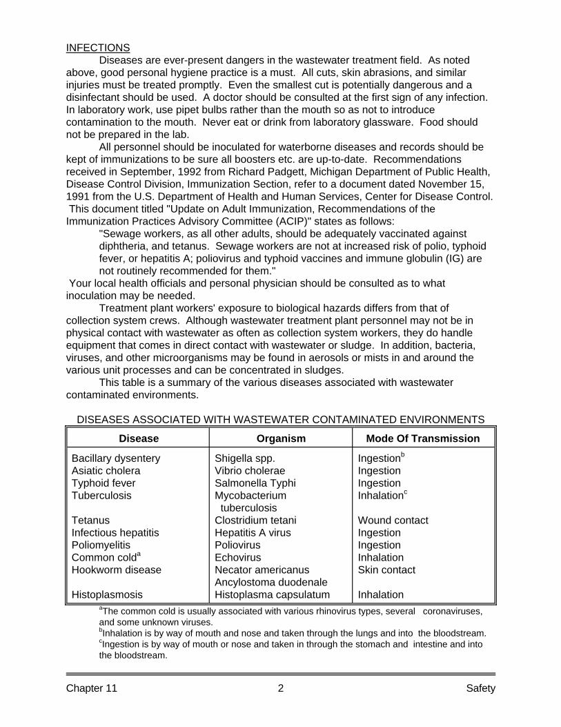
Chapter 11 2 Safety
INFECTIONS Diseases are ever-present dangers in the wastewater treatment field. As noted above, good personal hygiene practice is a must. All cuts, skin abrasions, and similar injuries must be treated promptly. Even the smallest cut is potentially dangerous and a disinfectant should be used. A doctor should be consulted at the first sign of any infection. In laboratory work, use pipet bulbs rather than the mouth so as not to introduce contamination to the mouth. Never eat or drink from laboratory glassware. Food should not be prepared in the lab. All personnel should be inoculated for waterborne diseases and records should be kept of immunizations to be sure all boosters etc. are up-to-date. Recommendations received in September, 1992 from Richard Padgett, Michigan Department of Public Health, Disease Control Division, Immunization Section, refer to a document dated November 15, 1991 from the U.S. Department of Health and Human Services, Center for Disease Control. This document titled "Update on Adult Immunization, Recommendations of the Immunization Practices Advisory Committee (ACIP)" states as follows: "Sewage workers, as all other adults, should be adequately vaccinated against
diphtheria, and tetanus. Sewage workers are not at increased risk of polio, typhoid fever, or hepatitis A; poliovirus and typhoid vaccines and immune globulin (IG) are not routinely recommended for them."
Your local health officials and personal physician should be consulted as to what inoculation may be needed. Treatment plant workers' exposure to biological hazards differs from that of collection system crews. Although wastewater treatment plant personnel may not be in physical contact with wastewater as often as collection system workers, they do handle equipment that comes in direct contact with wastewater or sludge. In addition, bacteria, viruses, and other microorganisms may be found in aerosols or mists in and around the various unit processes and can be concentrated in sludges. This table is a summary of the various diseases associated with wastewater contaminated environments. DISEASES ASSOCIATED WITH WASTEWATER CONTAMINATED ENVIRONMENTS
Disease Organism Mode Of Transmission
Bacillary dysentery Asiatic cholera Typhoid fever Tuberculosis Tetanus Infectious hepatitis Poliomyelitis Common colda
Hookworm disease Histoplasmosis
Shigella spp. Vibrio cholerae Salmonella Typhi Mycobacterium tuberculosis Clostridium tetani Hepatitis A virus Poliovirus Echovirus Necator americanus Ancylostoma duodenale Histoplasma capsulatum
Ingestionb
Ingestion Ingestion Inhalationc
Wound contact Ingestion Ingestion Inhalation Skin contact Inhalation
aThe common cold is usually associated with various rhinovirus types, several coronaviruses, and some unknown viruses.
bInhalation is by way of mouth and nose and taken through the lungs and into the bloodstream. cIngestion is by way of mouth or nose and taken in through the stomach and intestine and into
the bloodstream.
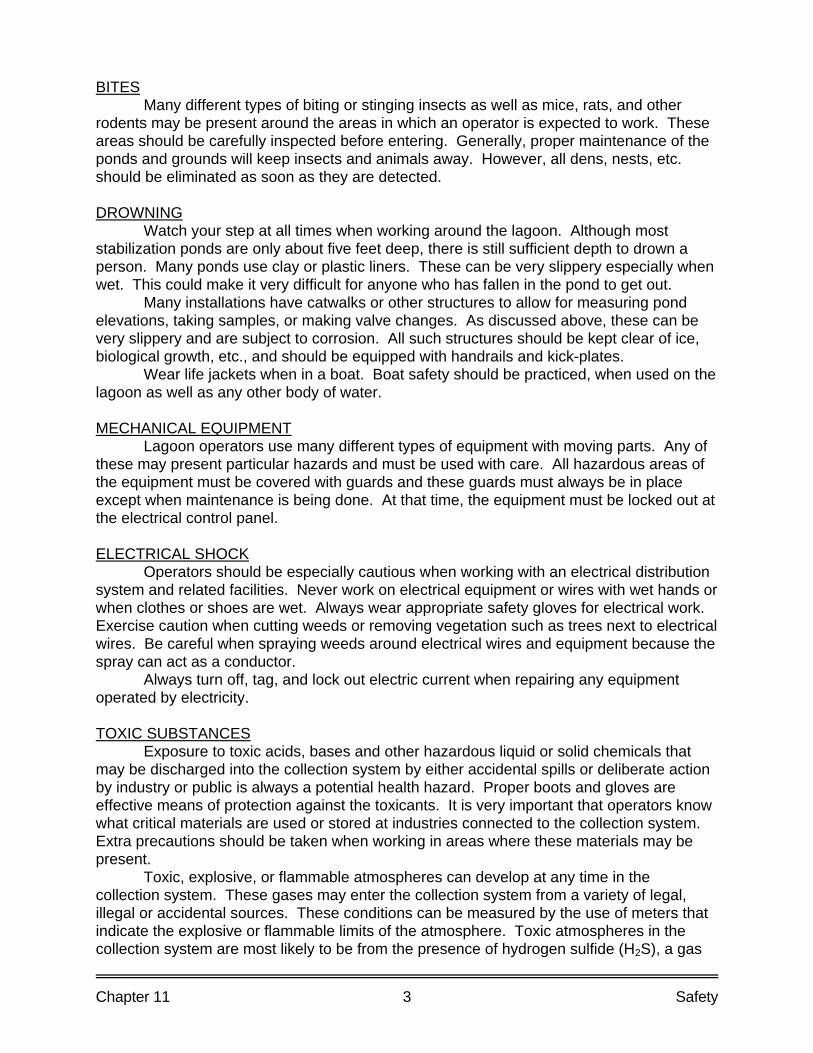
Chapter 11 3 Safety
BITES Many different types of biting or stinging insects as well as mice, rats, and other rodents may be present around the areas in which an operator is expected to work. These areas should be carefully inspected before entering. Generally, proper maintenance of the ponds and grounds will keep insects and animals away. However, all dens, nests, etc. should be eliminated as soon as they are detected. DROWNING Watch your step at all times when working around the lagoon. Although most stabilization ponds are only about five feet deep, there is still sufficient depth to drown a person. Many ponds use clay or plastic liners. These can be very slippery especially when wet. This could make it very difficult for anyone who has fallen in the pond to get out. Many installations have catwalks or other structures to allow for measuring pond elevations, taking samples, or making valve changes. As discussed above, these can be very slippery and are subject to corrosion. All such structures should be kept clear of ice, biological growth, etc., and should be equipped with handrails and kick-plates. Wear life jackets when in a boat. Boat safety should be practiced, when used on the lagoon as well as any other body of water. MECHANICAL EQUIPMENT Lagoon operators use many different types of equipment with moving parts. Any of these may present particular hazards and must be used with care. All hazardous areas of the equipment must be covered with guards and these guards must always be in place except when maintenance is being done. At that time, the equipment must be locked out at the electrical control panel. ELECTRICAL SHOCK Operators should be especially cautious when working with an electrical distribution system and related facilities. Never work on electrical equipment or wires with wet hands or when clothes or shoes are wet. Always wear appropriate safety gloves for electrical work. Exercise caution when cutting weeds or removing vegetation such as trees next to electrical wires. Be careful when spraying weeds around electrical wires and equipment because the spray can act as a conductor. Always turn off, tag, and lock out electric current when repairing any equipment operated by electricity. TOXIC SUBSTANCES Exposure to toxic acids, bases and other hazardous liquid or solid chemicals that may be discharged into the collection system by either accidental spills or deliberate action by industry or public is always a potential health hazard. Proper boots and gloves are effective means of protection against the toxicants. It is very important that operators know what critical materials are used or stored at industries connected to the collection system. Extra precautions should be taken when working in areas where these materials may be present. Toxic, explosive, or flammable atmospheres can develop at any time in the collection system. These gases may enter the collection system from a variety of legal, illegal or accidental sources. These conditions can be measured by the use of meters that indicate the explosive or flammable limits of the atmosphere. Toxic atmospheres in the collection system are most likely to be from the presence of hydrogen sulfide (H2S), a gas
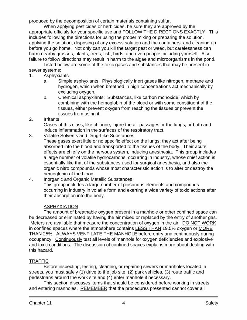
Chapter 11 4 Safety
produced by the decomposition of certain materials containing sulfur. When applying pesticides or herbicides, be sure they are approved by the appropriate officials for your specific use and FOLLOW THE DIRECTIONS EXACTLY. This includes following the directions for using the proper mixing or preparing the solution, applying the solution, disposing of any excess solution and the containers, and cleaning up before you go home. Not only can you kill the target pest or weed, but carelessness can harm nearby grasses, plants, trees, fish, birds, and even people including yourself. Also failure to follow directions may result in harm to the algae and microorganisms in the pond. Listed below are some of the toxic gases and substances that may be present in sewer systems: 1. Asphyxiants a. Simple asphyxiants: Physiologically inert gases like nitrogen, methane and
hydrogen, which when breathed in high concentrations act mechanically by excluding oxygen.
b. Chemical asphyxiants: Substances, like carbon monoxide, which by combining with the hemoglobin of the blood or with some constituent of the tissues, either prevent oxygen from reaching the tissues or prevent the tissues from using it.
2. Irritants Gases of this class, like chlorine, injure the air passages or the lungs, or both and
induce inflammation in the surfaces of the respiratory tract. 3. Volatile Solvents and Drug-Like Substances These gases exert little or no specific effect on the lungs; they act after being
absorbed into the blood and transported to the tissues of the body. Their acute effects are chiefly on the nervous system, inducing anesthesia. This group includes a large number of volatile hydrocarbons, occurring in industry, whose chief action is essentially like that of the substances used for surgical anesthesia, and also the organic nitro compounds whose most characteristic action is to alter or destroy the hemoglobin of the blood.
4. Inorganic and Organic Metallic Substances This group includes a large number of poisonous elements and compounds
occurring in industry in volatile form and exerting a wide variety of toxic actions after their absorption into the body.
ASPHYXIATION The amount of breathable oxygen present in a manhole or other confined space can be decreased or eliminated by having the air mixed or replaced by the entry of another gas. Meters are available that measure the concentration of oxygen in the air. DO NOT WORK in confined spaces where the atmosphere contains LESS THAN 19.5% oxygen or MORE THAN 25%. ALWAYS VENTILATE THE MANHOLE before entry and continuously during occupancy. Continuously test all levels of manhole for oxygen deficiencies and explosive and toxic conditions. The discussion of confined spaces explains more about dealing with this hazard. TRAFFIC Before inspecting, testing, cleaning, or repairing sewers or manholes located in streets, you must safely (1) drive to the job site, (2) park vehicles, (3) route traffic and pedestrians around the work site and (4) enter manhole if necessary. This section discusses items that should be considered before working in streets and entering manholes. REMEMBER that the procedures presented cannot cover all
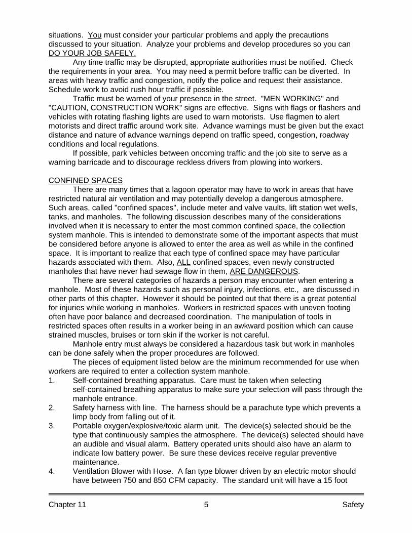
Chapter 11 5 Safety
situations. You must consider your particular problems and apply the precautions discussed to your situation. Analyze your problems and develop procedures so you can DO YOUR JOB SAFELY. Any time traffic may be disrupted, appropriate authorities must be notified. Check the requirements in your area. You may need a permit before traffic can be diverted. In areas with heavy traffic and congestion, notify the police and request their assistance. Schedule work to avoid rush hour traffic if possible. Traffic must be warned of your presence in the street. "MEN WORKING" and "CAUTION, CONSTRUCTION WORK" signs are effective. Signs with flags or flashers and vehicles with rotating flashing lights are used to warn motorists. Use flagmen to alert motorists and direct traffic around work site. Advance warnings must be given but the exact distance and nature of advance warnings depend on traffic speed, congestion, roadway conditions and local regulations. If possible, park vehicles between oncoming traffic and the job site to serve as a warning barricade and to discourage reckless drivers from plowing into workers. CONFINED SPACES There are many times that a lagoon operator may have to work in areas that have restricted natural air ventilation and may potentially develop a dangerous atmosphere. Such areas, called "confined spaces", include meter and valve vaults, lift station wet wells, tanks, and manholes. The following discussion describes many of the considerations involved when it is necessary to enter the most common confined space, the collection system manhole. This is intended to demonstrate some of the important aspects that must be considered before anyone is allowed to enter the area as well as while in the confined space. It is important to realize that each type of confined space may have particular hazards associated with them. Also, ALL confined spaces, even newly constructed manholes that have never had sewage flow in them, ARE DANGEROUS. There are several categories of hazards a person may encounter when entering a manhole. Most of these hazards such as personal injury, infections, etc., are discussed in other parts of this chapter. However it should be pointed out that there is a great potential for injuries while working in manholes. Workers in restricted spaces with uneven footing often have poor balance and decreased coordination. The manipulation of tools in restricted spaces often results in a worker being in an awkward position which can cause strained muscles, bruises or torn skin if the worker is not careful. Manhole entry must always be considered a hazardous task but work in manholes can be done safely when the proper procedures are followed. The pieces of equipment listed below are the minimum recommended for use when workers are required to enter a collection system manhole. 1. Self-contained breathing apparatus. Care must be taken when selecting
self-contained breathing apparatus to make sure your selection will pass through the manhole entrance.
2. Safety harness with line. The harness should be a parachute type which prevents a limp body from falling out of it.
3. Portable oxygen/explosive/toxic alarm unit. The device(s) selected should be the type that continuously samples the atmosphere. The device(s) selected should have an audible and visual alarm. Battery operated units should also have an alarm to indicate low battery power. Be sure these devices receive regular preventive maintenance.
4. Ventilation Blower with Hose. A fan type blower driven by an electric motor should have between 750 and 850 CFM capacity. The standard unit will have a 15 foot
Chapter 11 6 Safety
long hose, eight inches in diameter to conduct the blower air to the bottom of the manhole. Hose couplings and extensions are available for deep manhole (30 feet or over). Gasoline driven blowers are less desirable due to the noise factor and the possibility of producing undesirable fumes.
5. Manhole Enclosure. An enclosure that may be set up around the open manhole to prevent unauthorized persons from endangering the worker in the manhole or harming themselves.
6. Aluminum Ladders and/or Man Lifts. Lightweight aluminum ladders are often used in shallow manholes. They are easy to handle and to climb. Man lifts are used to avoid the use of ladders or steps in the manhole, wet wells and other below ground enclosures and to insure an exit for the below ground worker in case of emergencies.
7. Ropes and Buckets. Tools for use by workers in the manhole must be lowered to them and recovered from them by the use of a bucket. Lower the bucket with a hook rope with a safety clasp that will swivel.
8. Hard Hats and safety Glasses. No person should be allowed to enter a manhole without adequate head and eye protection. The full strength hard hat is recommended. If a face shield is used this will satisfy for the eye protection. Chin straps are almost a necessity in confined quarters.
9. Protective Clothing. As much of a person's body as possible should be covered with clothing that will prevent scrapes and abrasions. No one should ever be permitted in a manhole unless fully clothed, including footwear. Gloves of different types should be provided (cloth, leather, heavy rubber, lightweight rubber, etc.). Always thoroughly clean your hands before smoking, eating or leaving the job site. Clothes should be provided collection system workers, including shoes and boots with steel toes. If the worker furnishes own clothes, DO NOT WASH IN FAMILY WASHER OR AT LOCAL LAUNDROMAT, have washed by a commercial laundry firm.
10. Other Equipment. Cones, barricades, flags, etc. provided to ensure an effective barricade. A suitable equipped first-aid kit should be on hand and immediately available for use. After leaving a manhole, a strong soap and clean fresh water should be available to a worker for washing hands and face. Waterless antiseptic hand cleaners also are effective and approved for washing purposes. Paper towels may be used for the wiping process.
Workers in a wastewater collection system should have current immunizations against illnesses and diseases which might e encountered in the lagoon system. In cases where a manhole that must be entered is located close to the discharge of a hospital, clinical laboratory, veterinarian office and hospital, disinfectant may be required in the manhole and the upstream line one or two hours ahead of the scheduled entry. Contact the medical officer in charge of any facility immediately upstream from manholes and sewers in which you must work. This person can explain the procedures used, if any, by the medical facility, indicate if the threat to your health is greater than usual. Any worker entering a manhole should conform to the following rules at the time of entry. 1. Be in good health. If you are recovering from a recent illness or surgery, DO NOT
enter a manhole until fully recovered. 2. Not have a hangover, nor be under the influence of alcoholic beverages or drugs. 3. Have no open sores, skin irritations, fungus infection or serious sunburn. 4. Workers who do not require corrective glasses for manhole tasks are preferred for
such work. Other workers on a manhole entry crew should be in good health with necessary
Chapter 11 7 Safety
physical capacities to accomplish required work. If a manhole is especially filthy or odorous, wash down the manhole with high velocity, clear water before making entry. Before leaving the office, a crew briefing must be held. An updated map of the total collection system, indicating all industrial and commercial (including hospitals, laboratories, etc.) hook-ups, should be available, preferably wall mounted. Review with crew the discharges that may be expected in the section of the system being worked on. The nature of the job to be performed and individual crew assignments. This is a period of time in which the foreman or briefing officer can inspect each crew member and see if he is physically suited for the assigned job. Here is the place for any questions to be asked. Before leaving the maintenance yard, safety equipment must be carefully inspected and tested. Where functional capacities are doubtful, replacement equipment should be used while the suspected equipment is repaired. IF NO REPLACEMENT SAFETY EQUIPMENT IS AVAILABLE, POSTPONE PROJECT. A careful inventory and examination of the condition of all required tools, materials and equipment needed for the work should be made. Exposure to injury is greatest while a worker is entering or exiting a manhole, therefore, job organization and equipment requirements should be arranged to permit all work to be accomplished with a single entry and exit of the manhole. Just prior to entry, the foreman or crew leader should hold a short briefing on the project, the order of accomplishment and the safety rules that must be observed. All crew members should be fully informed of all aspects of the project and procedures that will be followed in the event of any emergency. The minimum crew for a worker to enter a manhole is three (3) workers. The worker who will go into the manhole, the attendant and an assistant on the surface. The arrangement of the safety and other equipment is generally accomplished by the entire crew, however, a support crew may be necessary to direct traffic, etc. With the proper barricades in place the portable explosive/oxygen/toxic alarm system is again checked and calibrated before removing the manhole cover. Test the manhole from top to bottom for oxygen deficiency, explosive and toxic (hydrogen sulfide) gases. Test for explosive mixtures before removing the manhole cover because removal of the cover may produce a spark and cause an explosion. It is helpful to know conditions in the manhole before any ventilation occurs. If an explosive atmosphere is discovered: 1. Immediately notify your supervisor of the condition and provide as many details as
possible, including location. Request notification of police and fire departments. 2. Do not remove the manhole cover. 3. Turn off any running engines. 4. Route vehicles around work area. 5. Inspect upstream and downstream manhole for explosive conditions to determine
extent of the problem. 6. Route traffic off the street to reduce potential for explosion. 7. Attempt to locate source of problem and correct situation. 8. Cautiously ventilate system with a large blower to eliminate explosive hazard. Try
ventilating from a safe upstream manhole in order to keep workers and equipment away from the explosive condition.
9. Be sure there is no smoking in the area. Never use hands to remove or replace the manhole cover. Always use a manhole lift approved by the safety agency that regulates your activities. Open manholes upstream and downstream from the work area to encourage natural
Chapter 11 8 Safety
ventilation of sewer. Cover open manholes with grating and place barricades around manhole to warn traffic and pedestrians. The area immediately around the manhole opening, including the manhole ring and lid ledge, should be cleaned and all loose debris removed. Sweep the area before removing the manhole cover and clean the ring ledge after the cover has been removed. The ventilation blower is started and the manhole atmosphere blown out 15 - 20 minutes before entry. The flower should be located at least ten feet from the manhole opening. If the blower has a gas driven engine, the exhaust must be downwind from the manhole. Once the man going into the hole has put on the safety harness and has the lifeline attached, the crew chief or foreman should check it for proper fit and attachment. Continue to use the alarm system to test for the presence of an oxygen deficiency and explosive gases in the manhole the entire time the worker is in the manhole. The attendant shall perform no other function, but keep a constant watch over the worker in the manhole. This worker should be careful to secure any objects he has in his shirt or jacket pockets so that they will not fall into the manhole when he bends over it. He must keep all tools away from the edge of the manhole. The attendant should carefully watch the worker and always listen and respond to the needs and condition of the worker in the manhole. If there are any indications of trouble such as unusual behavior or warning signals from the alarm system, immediately bring worker out of the manhole. Whenever a worker is in a manhole, continuously test the atmosphere for oxygen deficiency and for explosive and toxic gases. Proper ventilation generally will prevent any problems with the manhole atmosphere from developing except during a discharge up sewer. If the flammable gas level is within only 10 percent of the lower explosive limit (LEL), this is an indication that ventilation is ineffective. Manholes will have the capacity for strong odors and many of these odors can cause olfactory fatigue. This is a condition where a sharp odor or prolonged breathing of an odorous atmosphere will cause the sense of smell to be temporarily lost. If a smell of gas or some dangerous substance is noticed when first opening a manhole cover, the lack of such a smell at a later time must never be taken as an indication that the source of danger has been eliminated. Don't depend on odors to provide warnings. Where the atmosphere has been displaced by a gas that has no breathable oxygen in it, life expectancy for anyone entering the area is approximately 180 seconds with awareness of the problem lasting less than 30 seconds. Under these conditions, a power manlift is essential because the worker does not have the strength to climb out. Never allow anyone to enter an area where the oxygen level is below 19.5 percent or over 25% (by volume). The early warning signs of oxygen deficiency are: 1. Labored breathing (shortness of breath). 2. Chest heaving. 3. Change from usual responses (giddiness). A person who has been in a collection system manhole should have a hot shower and put on clean clothes before laving work at the end of the day. Under no circumstances should clothing worn in a manhole be worn home. Never expose your family to any contagious infection that might have come into contact with your clothing. No clothing worn in sewer maintenance or repair work should be worn home or washed with the family laundry. The crew leader or foreman has the responsibility to be sure all work is conducted in a safe and prescribed manner. If there is any doubt as to a safe working condition, contact the Michigan Department of Consumer and Industry Services, Safety Education and Training Division and have a consultant go over your system with you. These people are
Chapter 11 9 Safety
trainers, not enforcers. An employer must furnish a safe working area, by state law. FIRE EXTINGUISHERS Special consideration should be given to the installation and use of fire extinguishers at your lagoon site and lift stations. Very little has been done in the past in regards to fire protection, and the use of fire extinguishers. Fire extinguishers should be mounted on all maintenance vehicles, and in areas of potential fire danger: 1. Lift station electrical panel (but not down in lift station. 2. Any gasoline or diesel powered equipment. 3. Blower buildings. 4. Laboratories. CAUTION: DO NOT USE A FIRE EXTINGUISHER IN A CONFINED AIR SPACE. Recommended Type - A.B.C. Multi-Purpose 4-A:40 BC classification. Public Safety The relative amount of water surface of stabilization ponds is insignificant in comparison to the many natural bodies of open water in most localities. In some areas, however, stabilization ponds represent the only sizable body of water and have been sources of attraction to children as well as adults for recreation purposes. Incidents of boating, ice-skating, waterfowl hunting, and even swimming have been reported. This recreational use of the ponds should not be allowed because of the possibility of contamination or infection from pathogenic organisms as well as the possibility of drowning. Michigan requires that the pond area shall be enclosed with a suitable fence to preclude livestock and discourage trespassing. These should be located in such a manner that they will not interfere with maintenance of the dike slopes. A vehicle access gate of sufficient width to accommodate mowing equipment should be provided. All access gates should be provided with locks. Appropriate signs should be provided along the fence around the pond to designate the nature of the facility and advise against trespassing.
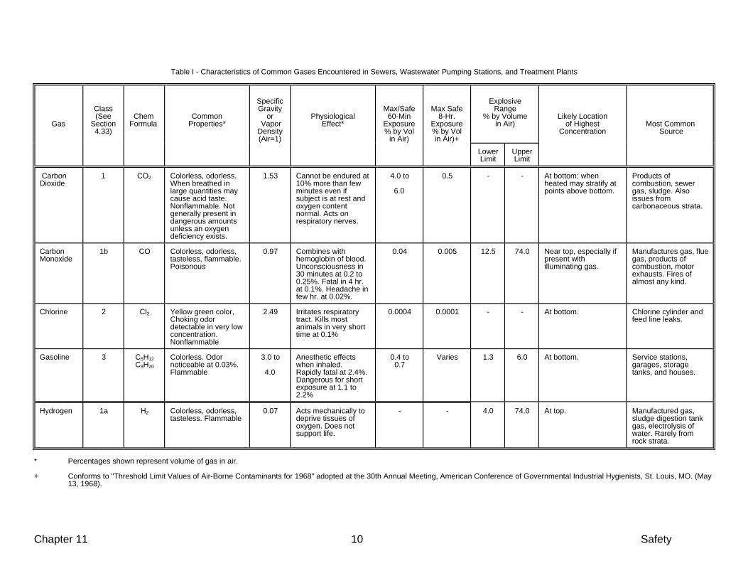
Chapter 11 10 Safety
Table I - Characteristics of Common Gases Encountered in Sewers, Wastewater Pumping Stations, and Treatment Plants
Gas
Class (See
Section 4.33)
Chem Formula
Common Properties*
Specific Gravity
or Vapor Density
(Air=1)
Physiological Effect*
Max/Safe
60-Min Exposure % by Vol
in Air)
Max Safe
8-Hr. Exposure % by Vol
in Air)+
Explosive Range % by Volume in Air)
Likely Location of Highest Concentration
Most Common Source
Lower Limit
Upper Limit
Carbon Dioxide
1 CO2 Colorless, odorless. When breathed in large quantities may cause acid taste. Nonflammable. Not generally present in dangerous amounts unless an oxygen deficiency exists.
1.53 Cannot be endured at 10% more than few minutes even if subject is at rest and oxygen content normal. Acts on respiratory nerves.
4.0 to
6.0
0.5 - - At bottom; when heated may stratify at points above bottom.
Products of combustion, sewer gas, sludge. Also issues from carbonaceous strata.
Carbon Monoxide
1b CO Colorless, odorless, tasteless, flammable. Poisonous
0.97 Combines with hemoglobin of blood. Unconsciousness in 30 minutes at 0.2 to 0.25%. Fatal in 4 hr. at 0.1%. Headache in few hr. at 0.02%.
0.04 0.005 12.5 74.0 Near top, especially if present with illuminating gas.
Manufactures gas, flue gas, products of combustion, motor exhausts. Fires of almost any kind.
Chlorine 2 Cl2 Yellow green color, Choking odor detectable in very low concentration. Nonflammable
2.49 Irritates respiratory tract. Kills most animals in very short time at 0.1%
0.0004 0.0001 - - At bottom. Chlorine cylinder and feed line leaks.
Gasoline 3 C5H12 C9H20
Colorless. Odor noticeable at 0.03%. Flammable
3.0 to
4.0
Anesthetic effects when inhaled. Rapidly fatal at 2.4%. Dangerous for short exposure at 1.1 to 2.2%
0.4 to 0.7
Varies 1.3 6.0 At bottom. Service stations, garages, storage tanks, and houses.
Hydrogen 1a H2 Colorless, odorless, tasteless. Flammable
0.07 Acts mechanically to deprive tissues of oxygen. Does not support life.
- - 4.0 74.0 At top. Manufactured gas, sludge digestion tank gas, electrolysis of water. Rarely from rock strata.
* Percentages shown represent volume of gas in air. + Conforms to "Threshold Limit Values of Air-Borne Contaminants for 1968" adopted at the 30th Annual Meeting, American Conference of Governmental Industrial Hygienists, St. Louis, MO. (May
13, 1968).
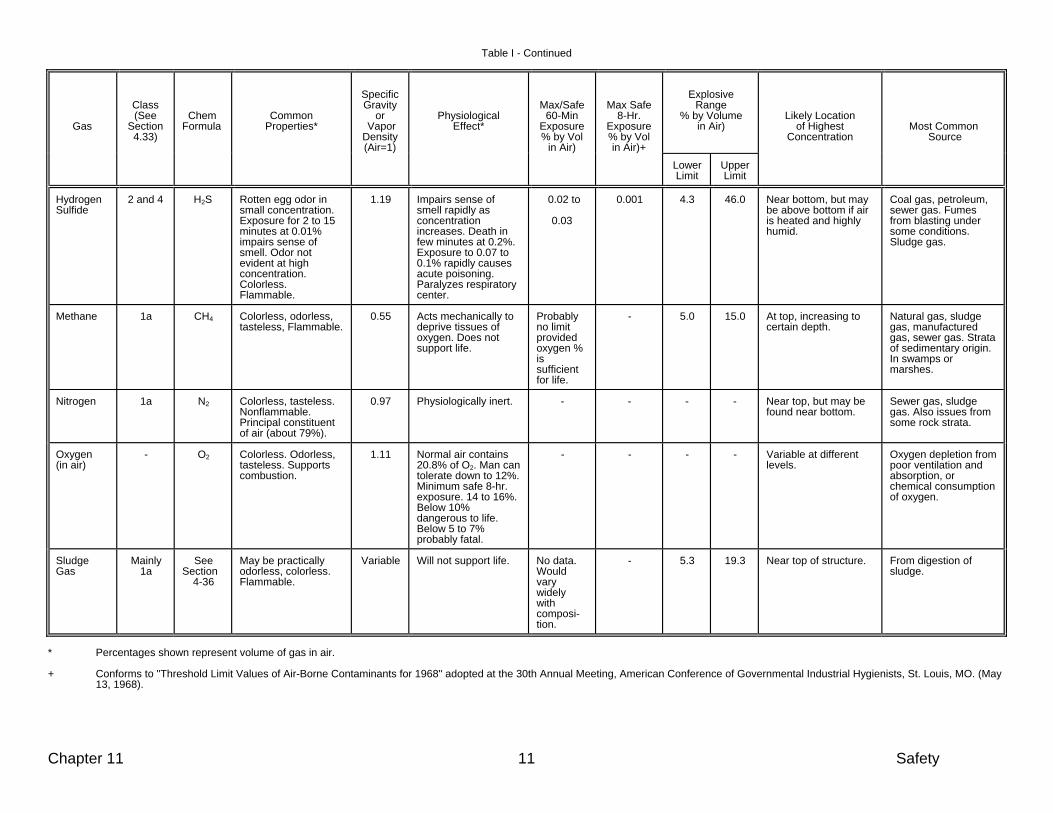
Chapter 11 11 Safety
Table I - Continued
Gas
Class (See
Section 4.33)
Chem Formula
Common Properties*
Specific Gravity
or Vapor Density
(Air=1)
Physiological Effect*
Max/Safe
60-Min Exposure % by Vol
in Air)
Max Safe
8-Hr. Exposure % by Vol
in Air)+
Explosive Range % by Volume in Air)
Likely Location of Highest Concentration
Most Common Source
Lower Limit
Upper Limit
Hydrogen Sulfide
2 and 4 H2S Rotten egg odor in small concentration. Exposure for 2 to 15 minutes at 0.01% impairs sense of smell. Odor not evident at high concentration. Colorless. Flammable.
1.19 Impairs sense of smell rapidly as concentration increases. Death in few minutes at 0.2%. Exposure to 0.07 to 0.1% rapidly causes acute poisoning. Paralyzes respiratory center.
0.02 to
0.03
0.001 4.3 46.0 Near bottom, but may be above bottom if air is heated and highly humid.
Coal gas, petroleum, sewer gas. Fumes from blasting under some conditions. Sludge gas.
Methane
1a CH4 Colorless, odorless, tasteless, Flammable.
0.55 Acts mechanically to deprive tissues of oxygen. Does not support life.
Probably no limit provided oxygen % is sufficient for life.
- 5.0 15.0 At top, increasing to certain depth.
Natural gas, sludge gas, manufactured gas, sewer gas. Strata of sedimentary origin. In swamps or marshes.
Nitrogen 1a N2 Colorless, tasteless. Nonflammable. Principal constituent of air (about 79%).
0.97 Physiologically inert. - - - - Near top, but may be found near bottom.
Sewer gas, sludge gas. Also issues from some rock strata.
Oxygen (in air)
- O2
Colorless. Odorless, tasteless. Supports combustion.
1.11
Normal air contains 20.8% of O2. Man can tolerate down to 12%. Minimum safe 8-hr. exposure. 14 to 16%. Below 10% dangerous to life. Below 5 to 7% probably fatal.
- - - - Variable at different levels.
Oxygen depletion from poor ventilation and absorption, or chemical consumption of oxygen.
Sludge Gas
Mainly 1a
See Section 4-36
May be practically odorless, colorless. Flammable.
Variable Will not support life. No data. Would vary widely with composi-tion.
- 5.3 19.3 Near top of structure. From digestion of sludge.
* Percentages shown represent volume of gas in air. + Conforms to "Threshold Limit Values of Air-Borne Contaminants for 1968" adopted at the 30th Annual Meeting, American Conference of Governmental Industrial Hygienists, St. Louis, MO. (May
13, 1968).


12. Aeration
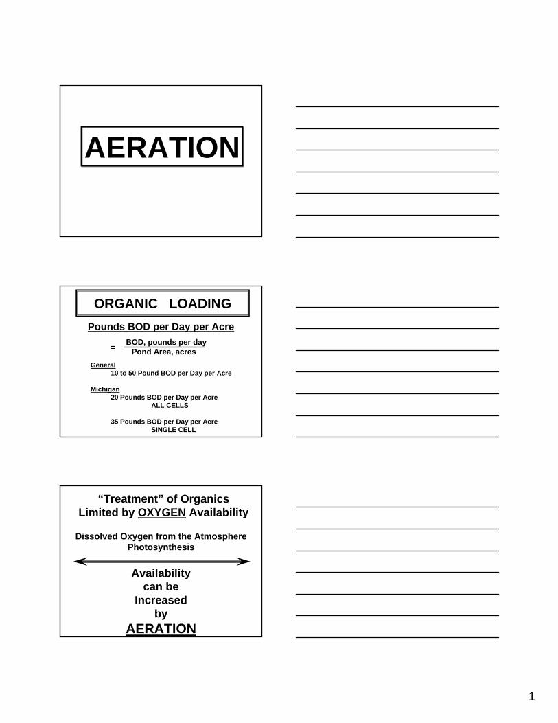
1
AERATION
ORGANIC LOADINGPounds BOD per Day per Acre
General10 to 50 Pound BOD per Day per Acre
Michigan20 Pounds BOD per Day per Acre
ALL CELLS
35 Pounds BOD per Day per AcreSINGLE CELL
BOD, pounds per dayPond Area, acres=
“Treatment” of OrganicsLimited by OXYGEN Availability
Dissolved Oxygen from the AtmospherePhotosynthesis
Availabilitycan be
Increasedby
AERATION
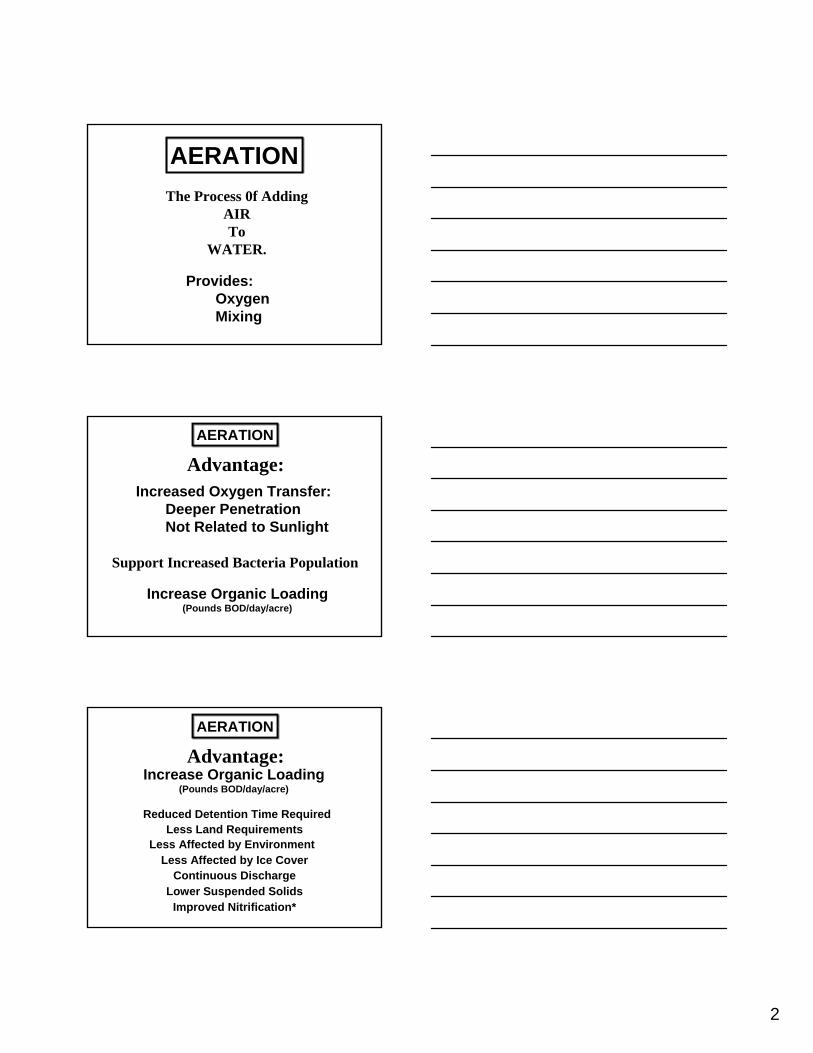
2
AERATIONThe Process 0f Adding
AIRTo
WATER.
Provides:OxygenMixing
AERATION
Advantage:Increased Oxygen Transfer:
Deeper PenetrationNot Related to Sunlight
Support Increased Bacteria Population
Increase Organic Loading(Pounds BOD/day/acre)
AERATION
Increase Organic Loading(Pounds BOD/day/acre)
Reduced Detention Time RequiredLess Land Requirements
Continuous DischargeLower Suspended Solids
Less Affected by Ice Cover
Improved Nitrification*
Less Affected by Environment
Advantage:
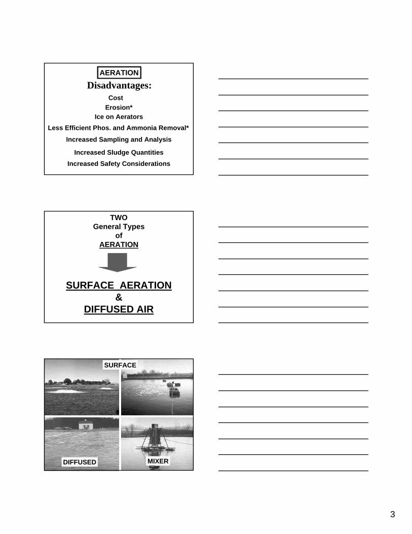
3
AERATION
Disadvantages:
Less Efficient Phos. and Ammonia Removal*
Erosion*
Increased Sludge Quantities
Ice on Aerators
Increased Safety Considerations
Increased Sampling and Analysis
Cost
TWOGeneral Types
ofAERATION
SURFACE AERATION&
DIFFUSED AIR
SURFACE
DIFFUSED MIXER
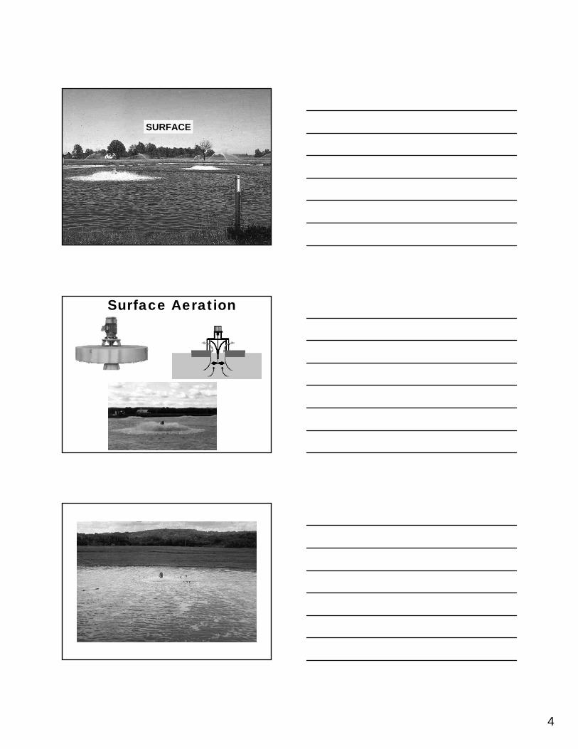
4
SURFACE
Surface Aeration
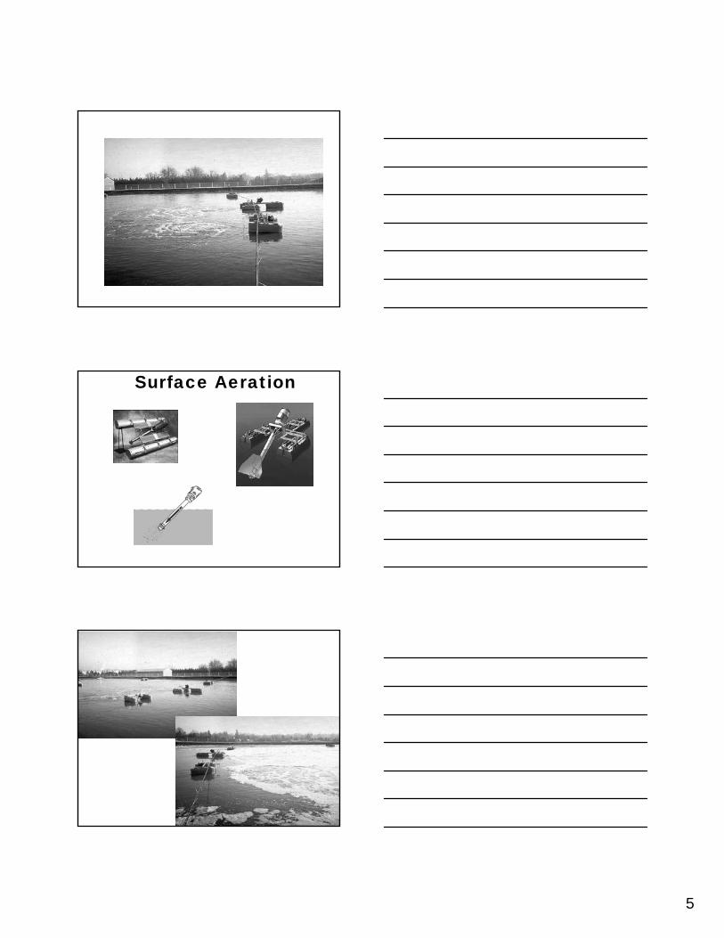
5
Surface Aeration
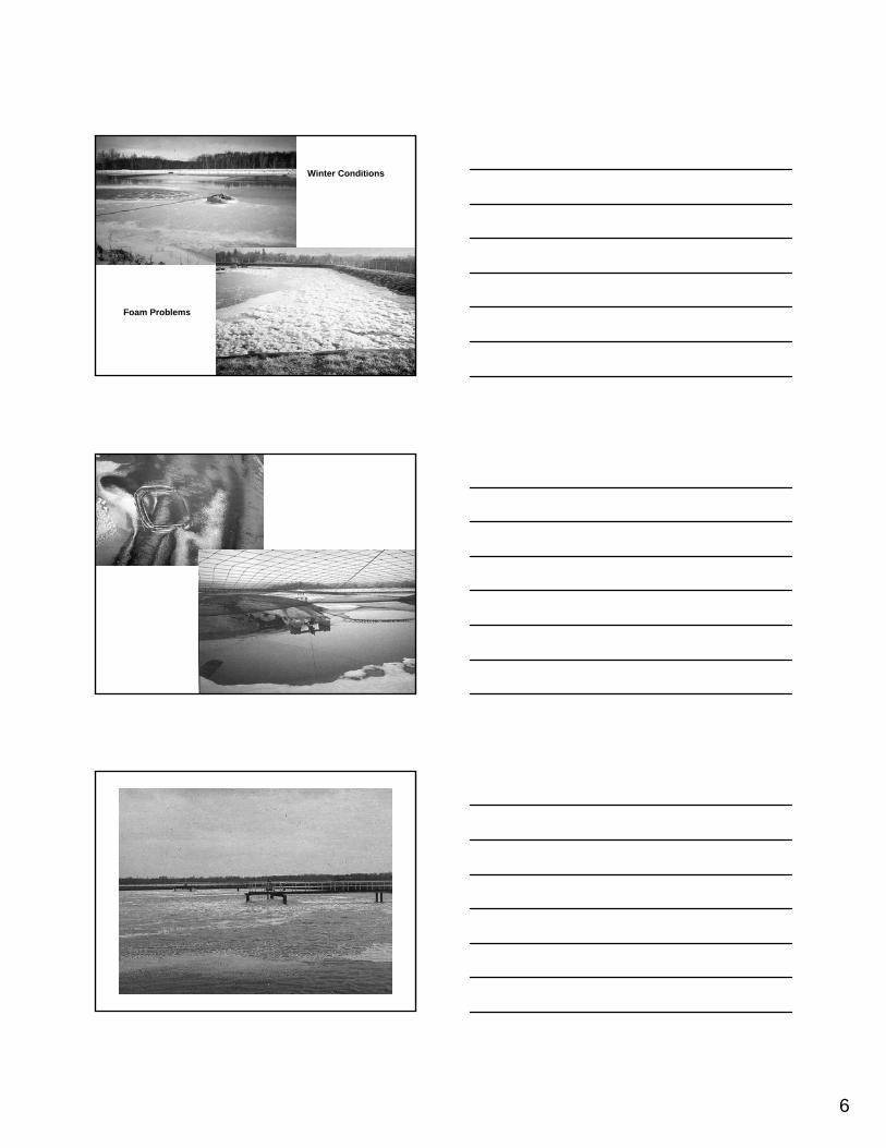
6
Winter Conditions
Foam Problems
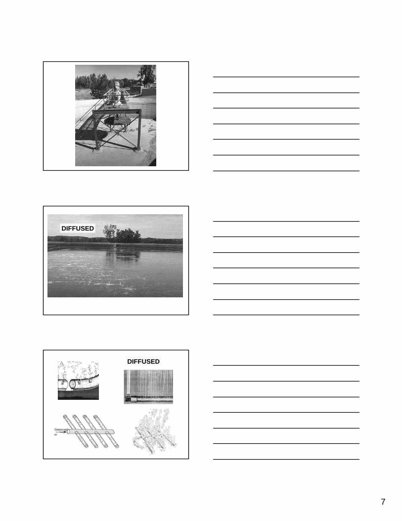
7
DIFFUSED
DIFFUSED
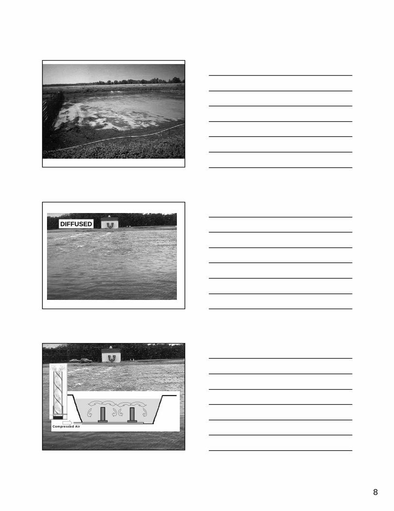
8
DIFFUSED
Compressed Air
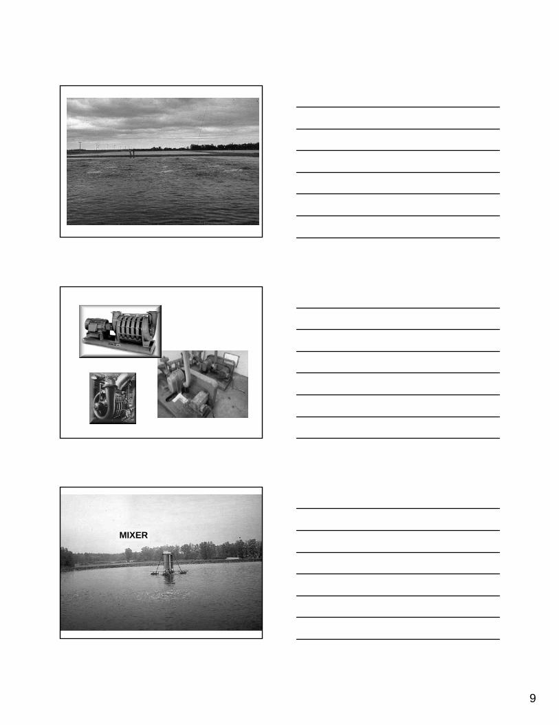
9
MIXER
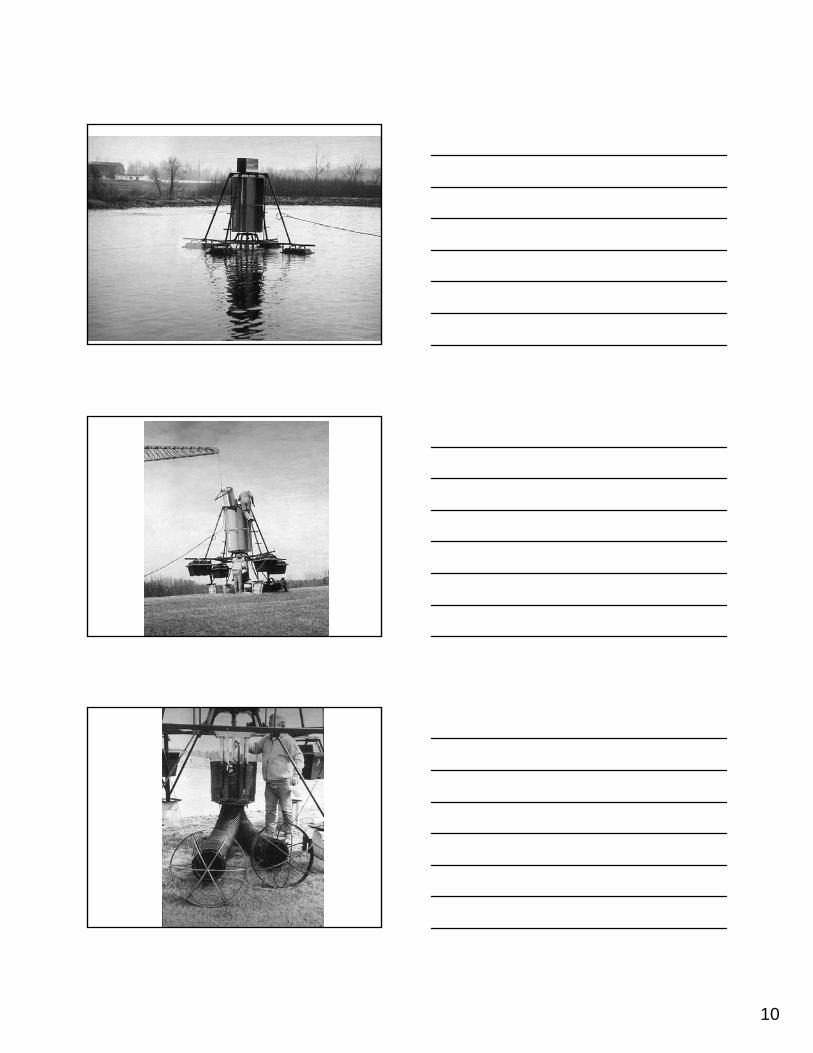
10
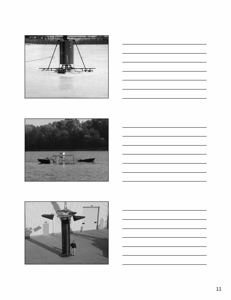
11
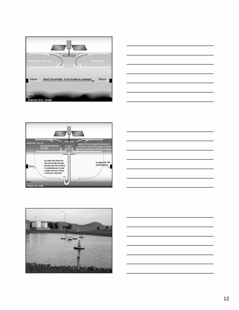
12
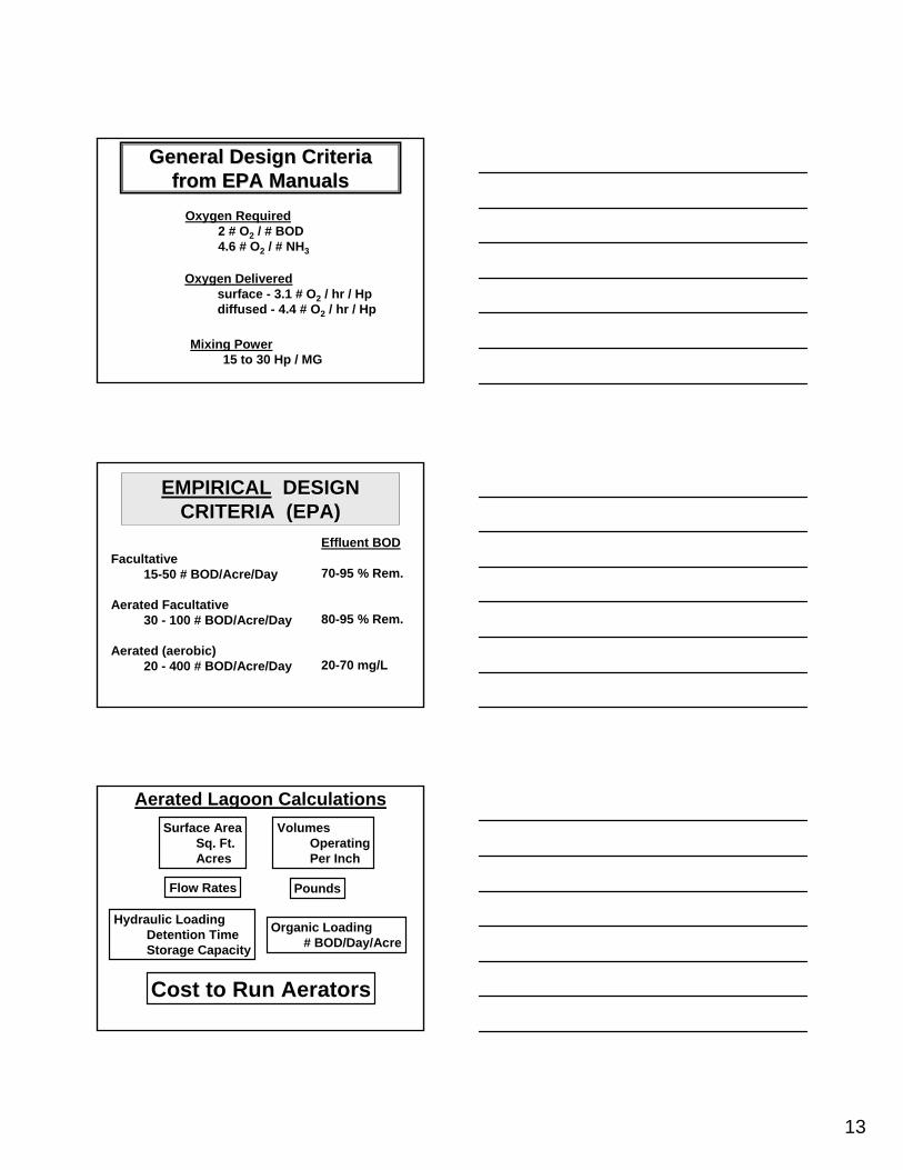
13
General Design CriteriaGeneral Design Criteriafrom EPA Manualsfrom EPA Manuals
Oxygen Required2 # O2 / # BOD4.6 # O2 / # NH3
Oxygen Deliveredsurface - 3.1 # O2 / hr / Hpdiffused - 4.4 # O2 / hr / Hp
Mixing Power15 to 30 Hp / MG
EMPIRICALEMPIRICAL DESIGN DESIGN CRITERIA (EPA)CRITERIA (EPA)
Facultative15-50 # BOD/Acre/Day
Aerated Facultative30 - 100 # BOD/Acre/Day
Aerated (aerobic)20 - 400 # BOD/Acre/Day
Effluent BOD
70-95 % Rem.
80-95 % Rem.
20-70 mg/L
Surface AreaSq. Ft.Acres
VolumesOperatingPer Inch
PoundsFlow Rates
Aerated Lagoon Calculations
Hydraulic LoadingDetention TimeStorage Capacity
Organic Loading# BOD/Day/Acre
Cost to Run Aerators

14
Calculate the cost to run a 25 horse power aerator 12 hours per day for 30 days if the cost of electricity is $0 .028 per kilowatt hour. (1HP = 746 watts)
1 HP = 746 watts = 0.746 kilowatts
25 HP = 25 X 0.746 kilowatts = 18.64 kilowatts
12 hours/day X 30 days = 360 hours
18.64 kilowatts X 360 hours = 6710 kilowatts hours
6710 kilowatts hours X $0.028 / kilowatt hour
= $187.88
Aerated Lagoon Calculations

13. Phosphorus Removal

REMOVAL OF PHOSPHORUS THE PROBLEM AND THE OBJECTIVE
It is a widely accepted fact that “well nourished” standing bodies of water support growths of aquatic plants, ranging from the minute, single celled algae to the coarse, rooted weeds and grasses. By “well nourished”, we refer to waters containing substantial quantities of nutrients which stimulate the growth of plants. Further, there is a direct relationship between the degree of nutrient enrichment of water and density of the resultant plant growth. The annual die-off of aquatic plants is followed by decay and release of the nutrients bound up in the plant cells. These nutrients are then available to promote an annual increase crop of plants with the eventual end result being a lake completely filled with decaying vegetation. This natural aging of lakes is called “Eutrophication”, a term derived from the Greek word Eutrophos - meaning “well nourished”.
A wide variety of nutrients, in varying balanced amounts are essential to aquatic plant growth and occur in natural waters, soils, plants and animals. These nutrients include primarily carbon, nitrogen and phosphorus, and trace amounts of metals. The annual increment of nutrients, under primitive conditions would be so minute that this natural process of a lake filling with decaying vegetation would be an extremely slow process when measured against the life span of man. However, natural enrichment when augmented by manmade enrichment may so increase the fertility of the water than the entire process of “aging” may be completed within a few years time. Uncontrolled drainage from heavily fertilized farmland, the discharge of treated wastewater in the absence of nutrient removal and drainage from sanitary landfills each contributes its share of fertility and thus accelerates the aging of a body of water.
In addition to the eventual loss of a body of water by gradual filling with vegetation, a variety of injuries or impairments to the use of the water may occur during the aging process. Some types of algae impart tastes and odors to water making treatment for potable water supplies very difficult. Dense growths of weeds or algae can impair the use of recreational waters due to their unsightliness, to the physical obstructions they present to boaters and other recreational water users. Subsequent decomposition of these dead plants may bring about an oxygen depletion resulting in fish kills from suffocation. Odors resulting from decay of dead plants present nuisance conditions and certain aquatic plant cells impart a deadly toxicity to the water. A widespread awareness and concern has developed over the accelerated aging of natural waters and related problems attributable to man-associated pollution.
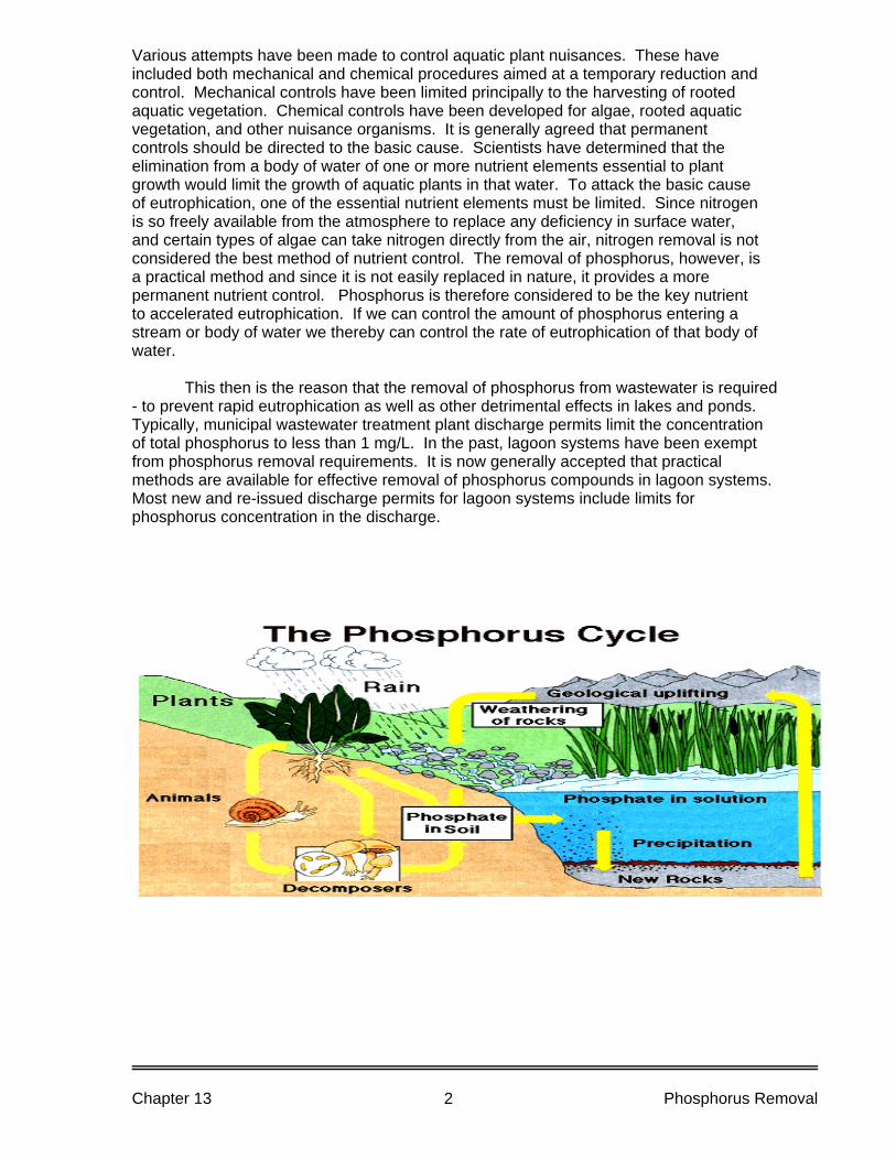
Various attempts have been made to control aquatic plant nuisances. These have included both mechanical and chemical procedures aimed at a temporary reduction and control. Mechanical controls have been limited principally to the harvesting of rooted aquatic vegetation. Chemical controls have been developed for algae, rooted aquatic vegetation, and other nuisance organisms. It is generally agreed that permanent controls should be directed to the basic cause. Scientists have determined that the elimination from a body of water of one or more nutrient elements essential to plant growth would limit the growth of aquatic plants in that water. To attack the basic cause of eutrophication, one of the essential nutrient elements must be limited. Since nitrogen is so freely available from the atmosphere to replace any deficiency in surface water, and certain types of algae can take nitrogen directly from the air, nitrogen removal is not considered the best method of nutrient control. The removal of phosphorus, however, is a practical method and since it is not easily replaced in nature, it provides a more permanent nutrient control. Phosphorus is therefore considered to be the key nutrient to accelerated eutrophication. If we can control the amount of phosphorus entering a stream or body of water we thereby can control the rate of eutrophication of that body of water.
This then is the reason that the removal of phosphorus from wastewater is required - to prevent rapid eutrophication as well as other detrimental effects in lakes and ponds. Typically, municipal wastewater treatment plant discharge permits limit the concentration of total phosphorus to less than 1 mg/L. In the past, lagoon systems have been exempt from phosphorus removal requirements. It is now generally accepted that practical methods are available for effective removal of phosphorus compounds in lagoon systems. Most new and re-issued discharge permits for lagoon systems include limits for phosphorus concentration in the discharge.
Chapter 13 Phosphorus Removal 2
REMOVAL OF PHOSPHORUS - PROCESS AND FACILITIES
Most secondary treatment methods of wastewater are oriented toward the stabilization of organic carbonaceous matter and are not efficient in phosphorus removal. The various types of wastewater treatment processes, including waste stabilization lagoon systems remove considerable phosphorus by biological assimilation and natural precipitation. However, few unmodified conventional treatment facilities are able to achieve the current water quality objective of removal to less than 1 mg/l of Total phosphorus. An additional process or modification to existing processes is needed. Sources of Phosphorus The primary source of phosphorus in domestic wastewater is from human wastes (feces, urine and waste food) and detergents containing phosphorus. Human wastes account for 30-50% of the phosphorus with 50-70% attributed to household detergents containing phosphorus. These percentages vary from community to community depending on life styles, industrial make-up and water supply. For example, in some communities it is necessary to control the iron content in the water supply. To accomplish this phosphorus compounds are fed to the water supply and thus can contribute from 2-20% of the phosphorus found in these community’s wastewater. Industrial wastewater discharged to the sanitary sewer system may also increase the phosphorus concentration in the wastewater. Forms of Phosphorus Phosphorus in wastewater is combined with oxygen in the compound known as phosphate (PO4). The three most common forms of phosphate in wastewater are orthophosphate, polyphosphates (condensed phosphates) and organic phosphate. Orthophosphate is the simplest form of phosphate, whose source is usually from household cleaners, and so-called heavy duty cleaning powders. Polyphosphates sometimes referred to as condensed phosphates, are more complex form than orthophosphate and enter the wastewater largely from detergents used either in the home or commercial establishments. Also phosphorus compounds used in the treatment of water supplies are usually in this form. The breakdown of poly or condensed phosphates results in the formation of orthophosphate. Organic Phosphate is a phosphate combined with an organic compound or structure. The source of this form is primarily from human wastes. The decomposition of organic phosphate results in phosphates being converted to orthophosphate. Biological treatment of wastewater converts most of the polyphosphates and organic phosphates to orthophosphate.
Chapter 13 Phosphorus Removal 3
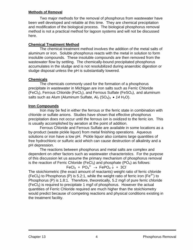
Methods of Removal
Two major methods for the removal of phosphorus from wastewater have been well developed and reliable at this time. They are chemical precipitation and modification of the biological process. The biological phosphorus removal method is not a practical method for lagoon systems and will not be discussed here. Chemical Treatment Method The chemical treatment method involves the addition of the metal salts of aluminum or iron. Soluble phosphorus reacts with the metal in solution to form insoluble compounds. These insoluble compounds are then removed from the wastewater flow by settling. The chemically-bound precipitated phosphorus accumulates in the sludge and is not resolubilized during anaerobic digestion or sludge disposal unless the pH is substantially lowered. Chemicals
The chemicals commonly used for the formation of a phosphorus precipitate in wastewater in Michigan are iron salts such as Ferric Chloride (FeCl3), Ferrous Chloride (FeCl2), and Ferrous Sulfate (FeSO4), and aluminum salts such as Alum (Aluminum Sulfate, Al2 (SO4)3 • 14 H2O). Iron Compounds Iron may be fed in either the ferrous or the ferric state in combination with chloride or sulfate anions. Studies have shown that effective phosphorus precipitation does not occur until the ferrous ion is oxidized to the ferric ion. This is usually accomplished by aeration at the point of addition. Ferrous Chloride and Ferrous Sulfate are available in some locations as a by-product (waste pickle liquor) from metal finishing operations. Aqueous solutions or iron have a low pH. Pickle liquor also contains large quantities of free hydrochloric or sulfuric acid which can cause destruction of alkalinity and a pH depression. The reactions between phosphorus and metal salts are complex and dependent on other factors such as wastewater characteristics. For the purpose of this discussion let us assume the primary mechanism of phosphorus removal is the reaction of Ferric Chloride (FeCl3) and phosphate (PO4) as follows:
FeCl3 + PO43- → FePO4 ↓ + 3Cl-
The stoichiometric (the exact amount of reactants) weight ratio of ferric chloride (FeCl3) to Phosphorus (P) is 5.2:1, while the weight ratio of ferric iron (Fe3+) to Phosphorus (P) is 1.8:1. Therefore, theoretically, 5.2 mg/l of pure ferric chloride (FeCl3) is required to precipitate 1 mg/l of phosphorus. However the actual quantities of Ferric Chloride required are much higher than the stoichiometry would predict because of competing reactions and physical conditions existing in the treatment facility.
Chapter 13 Phosphorus Removal 4
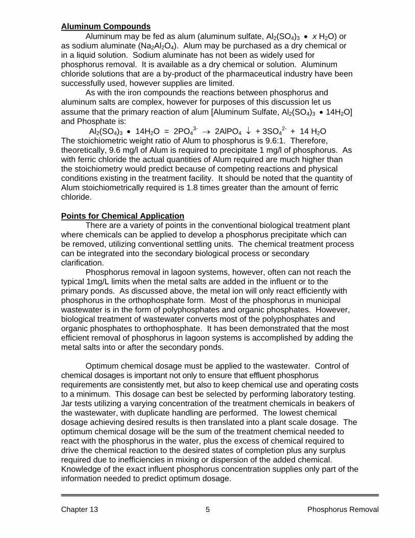
Aluminum Compounds Aluminum may be fed as alum (aluminum sulfate, Al2(SO4)3 • x H2O) or as sodium aluminate (Na2Al2O4). Alum may be purchased as a dry chemical or in a liquid solution. Sodium aluminate has not been as widely used for phosphorus removal. It is available as a dry chemical or solution. Aluminum chloride solutions that are a by-product of the pharmaceutical industry have been successfully used, however supplies are limited. As with the iron compounds the reactions between phosphorus and aluminum salts are complex, however for purposes of this discussion let us assume that the primary reaction of alum [Aluminum Sulfate, Al2(SO4)3 • 14H2O] and Phosphate is:
Al2(SO4)3 • 14H2O = 2PO43- → 2AlPO4 ↓ + 3SO4
2- + 14 H2O The stoichiometric weight ratio of Alum to phosphorus is 9.6:1. Therefore, theoretically, 9.6 mg/l of Alum is required to precipitate 1 mg/l of phosphorus. As with ferric chloride the actual quantities of Alum required are much higher than the stoichiometry would predict because of competing reactions and physical conditions existing in the treatment facility. It should be noted that the quantity of Alum stoichiometrically required is 1.8 times greater than the amount of ferric chloride. Points for Chemical Application There are a variety of points in the conventional biological treatment plant where chemicals can be applied to develop a phosphorus precipitate which can be removed, utilizing conventional settling units. The chemical treatment process can be integrated into the secondary biological process or secondary clarification. Phosphorus removal in lagoon systems, however, often can not reach the typical 1mg/L limits when the metal salts are added in the influent or to the primary ponds. As discussed above, the metal ion will only react efficiently with phosphorus in the orthophosphate form. Most of the phosphorus in municipal wastewater is in the form of polyphosphates and organic phosphates. However, biological treatment of wastewater converts most of the polyphosphates and organic phosphates to orthophosphate. It has been demonstrated that the most efficient removal of phosphorus in lagoon systems is accomplished by adding the metal salts into or after the secondary ponds. Optimum chemical dosage must be applied to the wastewater. Control of chemical dosages is important not only to ensure that effluent phosphorus requirements are consistently met, but also to keep chemical use and operating costs to a minimum. This dosage can best be selected by performing laboratory testing. Jar tests utilizing a varying concentration of the treatment chemicals in beakers of the wastewater, with duplicate handling are performed. The lowest chemical dosage achieving desired results is then translated into a plant scale dosage. The optimum chemical dosage will be the sum of the treatment chemical needed to react with the phosphorus in the water, plus the excess of chemical required to drive the chemical reaction to the desired states of completion plus any surplus required due to inefficiencies in mixing or dispersion of the added chemical. Knowledge of the exact influent phosphorus concentration supplies only part of the information needed to predict optimum dosage.
Chapter 13 Phosphorus Removal 5
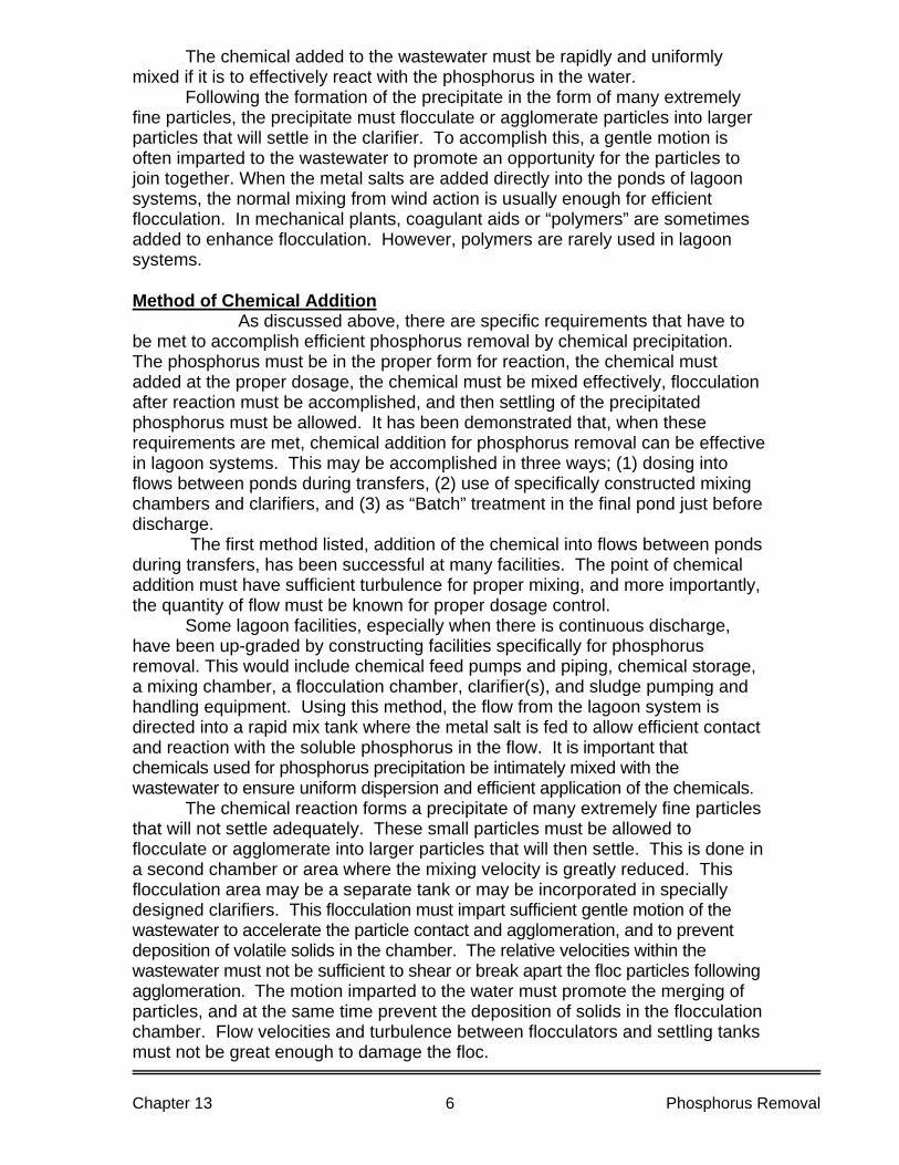
The chemical added to the wastewater must be rapidly and uniformly mixed if it is to effectively react with the phosphorus in the water. Following the formation of the precipitate in the form of many extremely fine particles, the precipitate must flocculate or agglomerate particles into larger particles that will settle in the clarifier. To accomplish this, a gentle motion is often imparted to the wastewater to promote an opportunity for the particles to join together. When the metal salts are added directly into the ponds of lagoon systems, the normal mixing from wind action is usually enough for efficient flocculation. In mechanical plants, coagulant aids or “polymers” are sometimes added to enhance flocculation. However, polymers are rarely used in lagoon systems. Method of Chemical Addition
As discussed above, there are specific requirements that have to be met to accomplish efficient phosphorus removal by chemical precipitation. The phosphorus must be in the proper form for reaction, the chemical must added at the proper dosage, the chemical must be mixed effectively, flocculation after reaction must be accomplished, and then settling of the precipitated phosphorus must be allowed. It has been demonstrated that, when these requirements are met, chemical addition for phosphorus removal can be effective in lagoon systems. This may be accomplished in three ways; (1) dosing into flows between ponds during transfers, (2) use of specifically constructed mixing chambers and clarifiers, and (3) as “Batch” treatment in the final pond just before discharge. The first method listed, addition of the chemical into flows between ponds during transfers, has been successful at many facilities. The point of chemical addition must have sufficient turbulence for proper mixing, and more importantly, the quantity of flow must be known for proper dosage control. Some lagoon facilities, especially when there is continuous discharge, have been up-graded by constructing facilities specifically for phosphorus removal. This would include chemical feed pumps and piping, chemical storage, a mixing chamber, a flocculation chamber, clarifier(s), and sludge pumping and handling equipment. Using this method, the flow from the lagoon system is directed into a rapid mix tank where the metal salt is fed to allow efficient contact and reaction with the soluble phosphorus in the flow. It is important that chemicals used for phosphorus precipitation be intimately mixed with the wastewater to ensure uniform dispersion and efficient application of the chemicals.
The chemical reaction forms a precipitate of many extremely fine particles that will not settle adequately. These small particles must be allowed to flocculate or agglomerate into larger particles that will then settle. This is done in a second chamber or area where the mixing velocity is greatly reduced. This flocculation area may be a separate tank or may be incorporated in specially designed clarifiers. This flocculation must impart sufficient gentle motion of the wastewater to accelerate the particle contact and agglomeration, and to prevent deposition of volatile solids in the chamber. The relative velocities within the wastewater must not be sufficient to shear or break apart the floc particles following agglomeration. The motion imparted to the water must promote the merging of particles, and at the same time prevent the deposition of solids in the flocculation chamber. Flow velocities and turbulence between flocculators and settling tanks must not be great enough to damage the floc.
Chapter 13 Phosphorus Removal 6
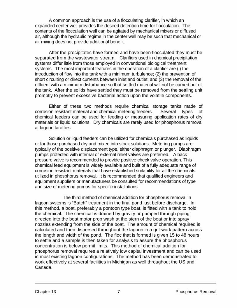
A common approach is the use of a flocculating clarifier, in which an expanded center well provides the desired detention time for flocculation. The contents of the flocculation well can be agitated by mechanical mixers or diffused air, although the hydraulic regime in the center well may be such that mechanical or air mixing does not provide additional benefit.
After the precipitates have formed and have been flocculated they must be separated from the wastewater stream. Clarifiers used in chemical precipitation systems differ little from those employed in conventional biological treatment systems. The most important features in the operation of a clarifier are (l) the introduction of flow into the tank with a minimum turbulence; (2) the prevention of short circuiting or direct currents between inlet and outlet; and (3) the removal of the effluent with a minimum disturbance so that settled material will not be carried out of the tank. After the solids have settled they must be removed from the settling unit promptly to prevent excessive bacterial action upon the volatile components. Either of these two methods require chemical storage tanks made of corrosion resistant material and chemical metering feeders. Several types of chemical feeders can be used for feeding or measuring application rates of dry materials or liquid solutions. Dry chemicals are rarely used for phosphorus removal at lagoon facilities. Solution or liquid feeders can be utilized for chemicals purchased as liquids or for those purchased dry and mixed into stock solutions. Metering pumps are typically of the positive displacement type, either diaphragm or plunger. Diaphragm pumps protected with internal or external relief valves are preferred. A back pressure valve is recommended to provide positive check valve operation. This chemical feed equipment is widely available and built of a fully adequate range of corrosion resistant materials that have established suitability for all the chemicals utilized in phosphorus removal. It is recommended that qualified engineers and equipment suppliers or manufacturers be consulted for recommendations of type and size of metering pumps for specific installations.
The third method of chemical addition for phosphorus removal in lagoon systems is “Batch” treatment in the final pond just before discharge. In this method, a boat, preferably a pontoon type boat, is fitted with a tank to hold the chemical. The chemical is drained by gravity or pumped through piping directed into the boat motor prop wash at the stern of the boat or into spray nozzles extending from the side of the boat. The amount of chemical required is calculated and then dispersed throughout the lagoon in a grit-work pattern across the length and width of the pond. The floc that is formed is given 15 to 48 hours to settle and a sample is then taken for analysis to assure the phosphorus concentration is below permit limits. This method of chemical addition for phosphorus removal requires a relatively low capital investment and can be used in most existing lagoon configurations. The method has been demonstrated to work effectively at several facilities in Michigan as well throughout the US and Canada.
Chapter 13 Phosphorus Removal 7
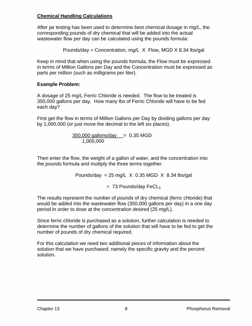
Chemical Handling Calculations After jar testing has been used to determine best chemical dosage in mg/L, the corresponding pounds of dry chemical that will be added into the actual wastewater flow per day can be calculated using the pounds formula: Pounds/day = Concentration, mg/L X Flow, MGD X 8.34 lbs/gal Keep in mind that when using the pounds formula, the Flow must be expressed in terms of Million Gallons per Day and the Concentration must be expressed as parts per million (such as milligrams per liter). Example Problem: A dosage of 25 mg/L Ferric Chloride is needed. The flow to be treated is 350,000 gallons per day. How many lbs of Ferric Chloride will have to be fed each day? First get the flow in terms of Million Gallons per Day by dividing gallons per day by 1,000,000 (or just move the decimal to the left six places).
350,000 gallons/day = 0.35 MGD 1,000,000
Then enter the flow, the weight of a gallon of water, and the concentration into the pounds formula and multiply the three terms together. Pounds/day = 25 mg/L X 0.35 MGD X 8.34 lbs/gal = 73 Pounds/day FeCL3 The results represent the number of pounds of dry chemical (ferric chloride) that would be added into the wastewater flow (350,000 gallons per day) in a one day period in order to dose at the concentration desired (25 mg/L). Since ferric chloride is purchased as a solution, further calculation is needed to determine the number of gallons of the solution that will have to be fed to get the number of pounds of dry chemical required. For this calculation we need two additional pieces of information about the solution that we have purchased; namely the specific gravity and the percent solution.
Chapter 13 Phosphorus Removal 8
Specific Gravity The Specific Gravity of a solution is the number of times heavier or lighter the solution is than water. We know that 1 gallon of water weighs 8.34 lbs. The Specific gravity of water = 1.000 If a chemical solution has a specific gravity of 1.510, the solution is 1.510 times heavier than an equal volume of water. Therefore, we can determine the weight of a gallon of a solution if we know the specific gravity. 8.34 lbs/gallon X 1.510 = 12.59 lbs/gallon The specific gravity of the chemical solution purchased should be provided by the chemical supplier. It can be determined in a couple of ways if the specific gravity has not been provided. Probably the easiest way to determine the specific gravity of a solution is by using a “hydrometer”. This a a narrow glass tube with a bulb in the middle and a weight inside the tube at the bottom. The tube has a graduated scale which indicates specific gravity, usually calibrated by the factory at 20 degrees C.
The hydrometer is allowed to float in the solution to be tested. The greater the specific gravity of the solution, the less the hydrometer will sink into it. The specific gravity of the solution is read on the scale at the surface of the solution.
Since the hydrometer is calibrated at 20 degrees C, specific gravity should be determined on solutions which are at room temperature. Another way to determine specific gravity is to use an analytical balance to weigh a carefully measured volume of the solution. Water weighs 1 gram per milliliter at 20 degrees C. Thus, a solution that weighs 1.43 grams per milliliter has a specific gravity of 1.43.
Chapter 13 Phosphorus Removal 9
Percent Solution In addition to specific gravity, the chemical provider should also provide the concentration of the solution, usually expressed as percent by weight. For instance, a 35 % solution means that 35 % of the weight of that solution is due to the dry chemical dissolved in it. So if we have 100 pounds of a 35 % ferric chloride solution, we have 35 pounds of dry ferric chloride. Since we can determine the weight of a gallon of the solution if we have the specific gravity, we can easily find the weight of dry chemical in each gallon of a chemical solution if we know the specific gravity of the solution and the concentration in percent by weight. The pounds of dry chemical in each gallon of the solution is equal to the specific gravity multiplied by the weight of a gallon of water (8.34 lbs/gal) and multiplied by the decimal equivalent of the percent solution. Example: The chemical to be used is a 40 % solution and has a specific gravity of 1.43 A. Determine the weight of a gallon of the solution. 8.34 lbs/gallon X 1.43 = 11.93 pounds per gallon liquid B. Determine the pounds of dry chemical in each gallon. 11.93 pounds X 40 lbs dry chem. = 4.77 pounds dry chemical / gallon 100 lbs solution OR 11.93 pounds X 0.40 = 4.77 pounds dry chemical / gallon Chemical Feed Rates At this point, the bench test has been used to determine the concentration of the coagulant that must occur in the wastewater to achieve the desired effect. Given the wastewater flow that must be treated, the number of pounds of coagulant that must be fed each day may be calculated. The specific gravity and the percent concentration of the solution may be used to calculate number of pounds of dry coagulant in each gallon of the purchased chemical solution.
Chapter 13 Phosphorus Removal 10
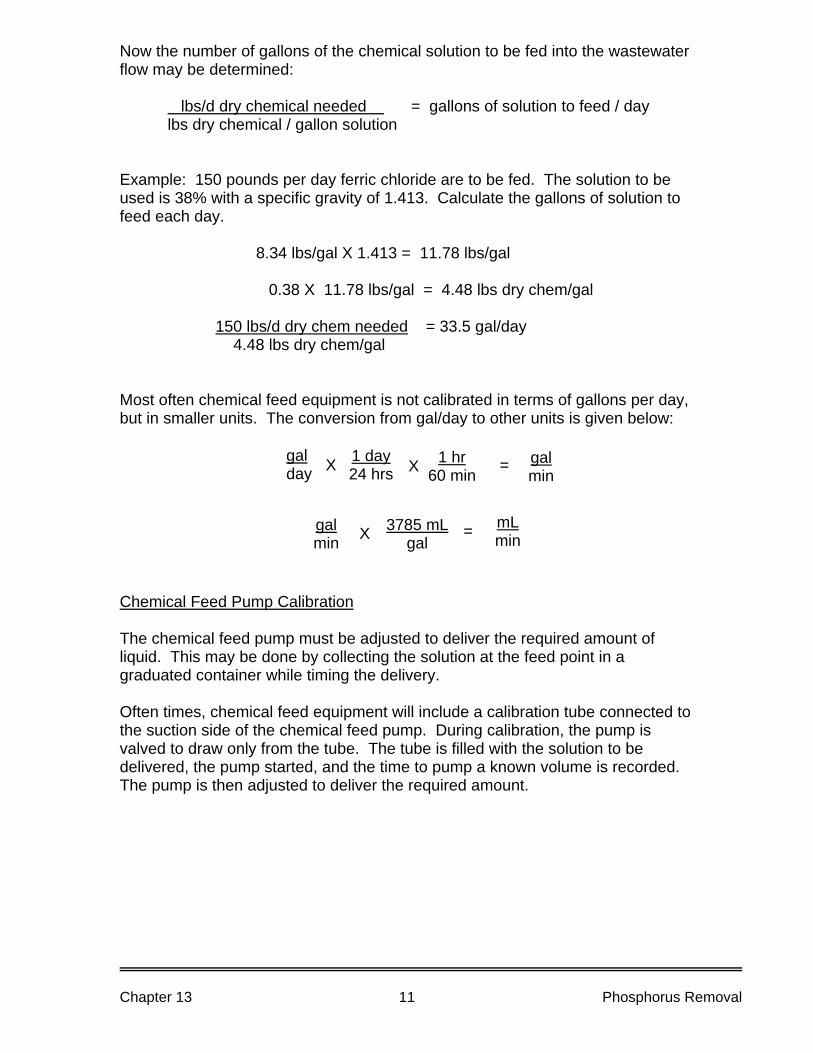
Now the number of gallons of the chemical solution to be fed into the wastewater flow may be determined: lbs/d dry chemical needed . = gallons of solution to feed / day lbs dry chemical / gallon solution Example: 150 pounds per day ferric chloride are to be fed. The solution to be used is 38% with a specific gravity of 1.413. Calculate the gallons of solution to feed each day. 8.34 lbs/gal X 1.413 = 11.78 lbs/gal 0.38 X 11.78 lbs/gal = 4.48 lbs dry chem/gal 150 lbs/d dry chem needed = 33.5 gal/day 4.48 lbs dry chem/gal Most often chemical feed equipment is not calibrated in terms of gallons per day, but in smaller units. The conversion from gal/day to other units is given below: gal
day X 1 day 24 hrs X 1 hr
60 min = gal min
3785 mL gal
= gal min X
mL min
Chemical Feed Pump Calibration The chemical feed pump must be adjusted to deliver the required amount of liquid. This may be done by collecting the solution at the feed point in a graduated container while timing the delivery. Often times, chemical feed equipment will include a calibration tube connected to the suction side of the chemical feed pump. During calibration, the pump is valved to draw only from the tube. The tube is filled with the solution to be delivered, the pump started, and the time to pump a known volume is recorded. The pump is then adjusted to deliver the required amount.
Chapter 13 Phosphorus Removal 11
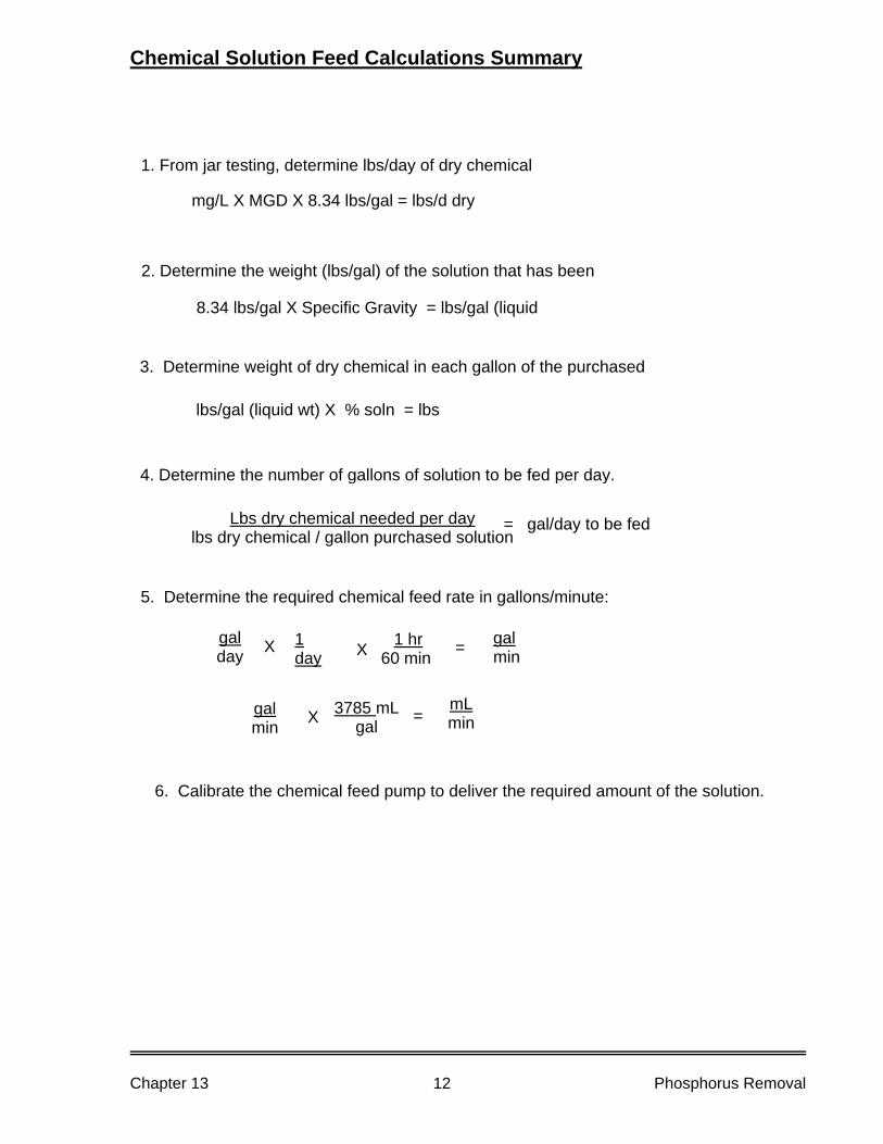
Chemical Solution Feed Calculations Summary
5. Determine the required chemical feed rate in gallons/minute:
galday X 1
day X 1 hr60 min = gal
min
mg/L X MGD X 8.34 lbs/gal = lbs/d dry
8.34 lbs/gal X Specific Gravity = lbs/gal (liquid
lbs/gal (liquid wt) X % soln = lbs
Lbs dry chemical needed per daylbs dry chemical / gallon purchased solution
1. From jar testing, determine lbs/day of dry chemical
2. Determine the weight (lbs/gal) of the solution that has been
3. Determine weight of dry chemical in each gallon of the purchased
4. Determine the number of gallons of solution to be fed per day.
= gal/day to be fed
3785 mL gal = gal
min X mL min
6. Calibrate the chemical feed pump to deliver the required amount of the solution.
Chapter 13 Phosphorus Removal 12
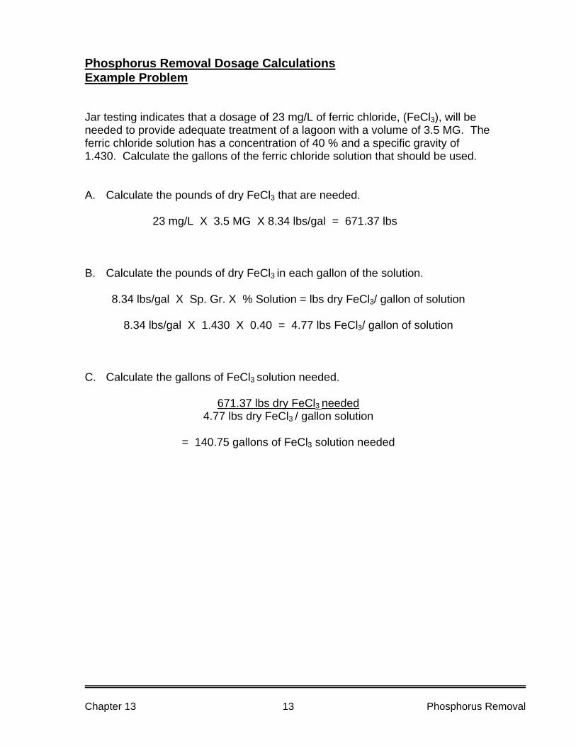
Phosphorus Removal Dosage Calculations Example Problem Jar testing indicates that a dosage of 23 mg/L of ferric chloride, (FeCl3), will be needed to provide adequate treatment of a lagoon with a volume of 3.5 MG. The ferric chloride solution has a concentration of 40 % and a specific gravity of 1.430. Calculate the gallons of the ferric chloride solution that should be used. A. Calculate the pounds of dry FeCl3 that are needed. 23 mg/L X 3.5 MG X 8.34 lbs/gal = 671.37 lbs B. Calculate the pounds of dry FeCl3 in each gallon of the solution.
8.34 lbs/gal X Sp. Gr. X % Solution = lbs dry FeCl3/ gallon of solution
8.34 lbs/gal X 1.430 X 0.40 = 4.77 lbs FeCl3/ gallon of solution C. Calculate the gallons of FeCl3 solution needed.
671.37 lbs dry FeCl3 needed 4.77 lbs dry FeCl3 / gallon solution
= 140.75 gallons of FeCl3 solution needed
Chapter 13 Phosphorus Removal 13
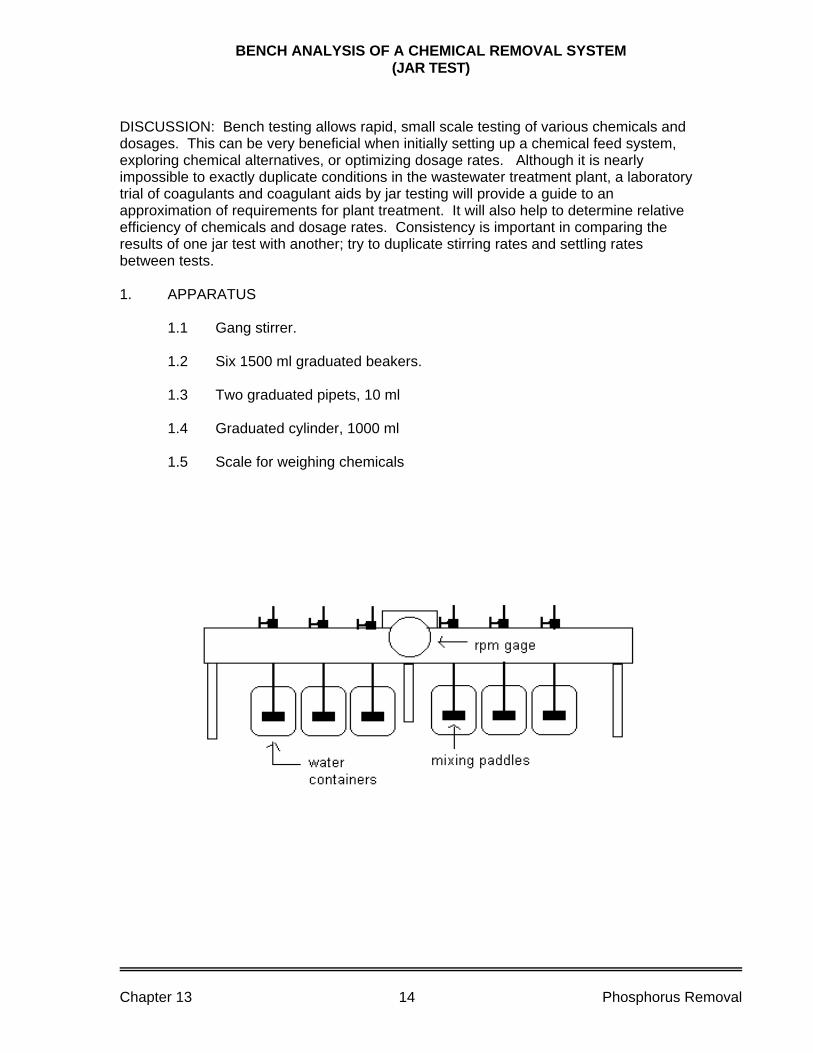
BENCH ANALYSIS OF A CHEMICAL REMOVAL SYSTEM (JAR TEST)
DISCUSSION: Bench testing allows rapid, small scale testing of various chemicals and dosages. This can be very beneficial when initially setting up a chemical feed system, exploring chemical alternatives, or optimizing dosage rates. Although it is nearly impossible to exactly duplicate conditions in the wastewater treatment plant, a laboratory trial of coagulants and coagulant aids by jar testing will provide a guide to an approximation of requirements for plant treatment. It will also help to determine relative efficiency of chemicals and dosage rates. Consistency is important in comparing the results of one jar test with another; try to duplicate stirring rates and settling rates between tests. 1. APPARATUS
1.1 Gang stirrer.
1.2 Six 1500 ml graduated beakers.
1.3 Two graduated pipets, 10 ml
1.4 Graduated cylinder, 1000 ml
1.5 Scale for weighing chemicals
Chapter 13 Phosphorus Removal 14
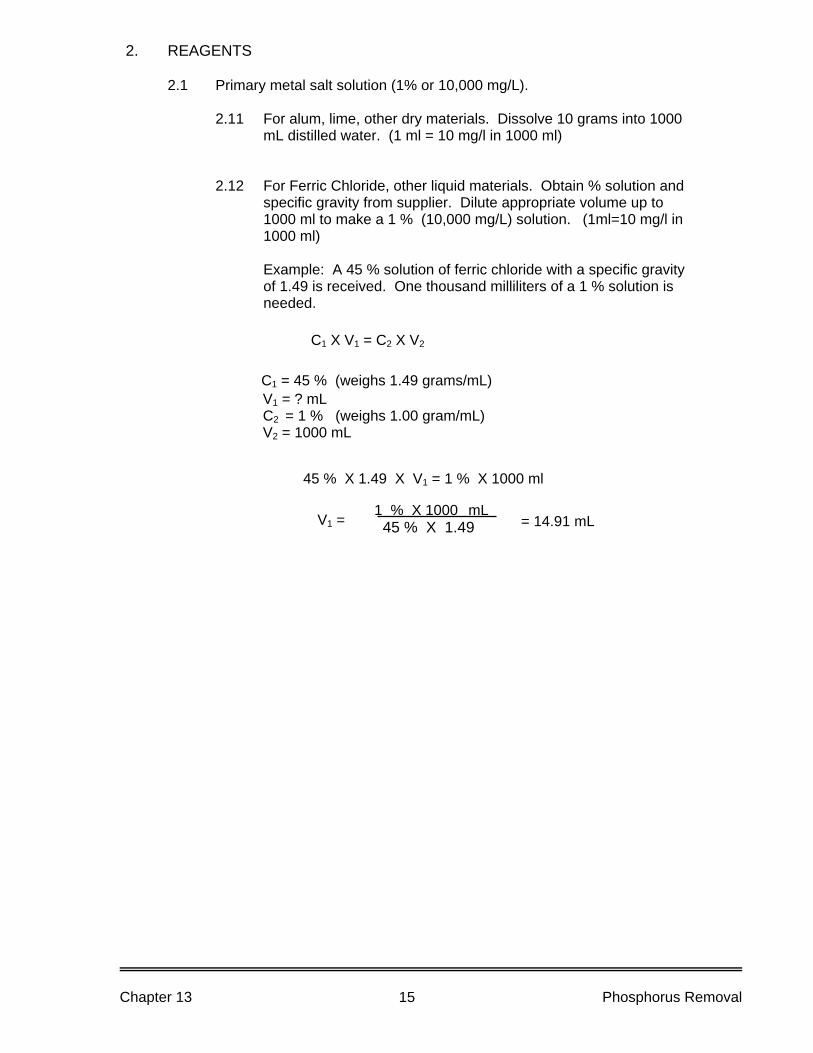
2. REAGENTS
2.1 Primary metal salt solution (1% or 10,000 mg/L).
2.11 For alum, lime, other dry materials. Dissolve 10 grams into 1000 mL distilled water. (1 ml = 10 mg/l in 1000 ml)
2.12 For Ferric Chloride, other liquid materials. Obtain % solution and specific gravity from supplier. Dilute appropriate volume up to 1000 ml to make a 1 % (10,000 mg/L) solution. (1ml=10 mg/l in 1000 ml)
Example: A 45 % solution of ferric chloride with a specific gravity
of 1.49 is received. One thousand milliliters of a 1 % solution is needed.
45 % X 1.49 X V1 = 1 % X 1000 ml
C1 X V1 = C2 X V2
C1 = 45 % (weighs 1.49 grams/mL) V1 = ? mL C2 = 1 % (weighs 1.00 gram/mL) V2 = 1000 mL
1 % X 1000 mL 45 % X 1.49 V1 = = 14.91 mL
Chapter 13 Phosphorus Removal 15
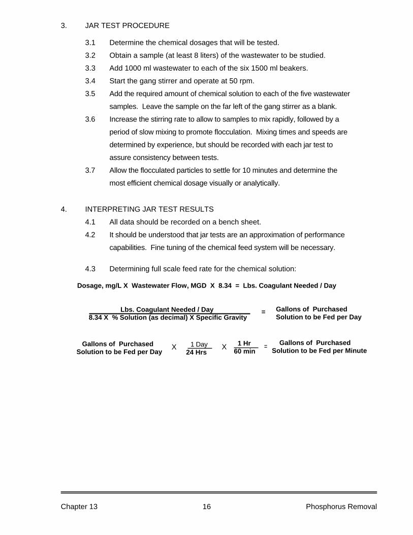
3. JAR TEST PROCEDURE
3.1 Determine the chemical dosages that will be tested.
3.2 Obtain a sample (at least 8 liters) of the wastewater to be studied.
3.3 Add 1000 ml wastewater to each of the six 1500 ml beakers.
3.4 Start the gang stirrer and operate at 50 rpm.
3.5 Add the required amount of chemical solution to each of the five wastewater
samples. Leave the sample on the far left of the gang stirrer as a blank.
3.6 Increase the stirring rate to allow to samples to mix rapidly, followed by a
period of slow mixing to promote flocculation. Mixing times and speeds are
determined by experience, but should be recorded with each jar test to
assure consistency between tests.
3.7 Allow the flocculated particles to settle for 10 minutes and determine the
most efficient chemical dosage visually or analytically.
4. INTERPRETING JAR TEST RESULTS
4.1 All data should be recorded on a bench sheet.
4.2 It should be understood that jar tests are an approximation of performance
capabilities. Fine tuning of the chemical feed system will be necessary.
4.3 Determining full scale feed rate for the chemical solution:
Dosage, mg/L X Wastewater Flow, MGD X 8.34 = Lbs. Coagulant Needed / Day
Lbs. Coagulant Needed / Day 8.34 X % Solution (as decimal) X Specific Gravity
Gallons of Purchased Solution to be Fed per Day
=
1 Day 24 Hrs
1 Hr 60 min X = Gallons of Purchased
Solution to be Fed per Minute X Gallons of Purchased Solution to be Fed per Day
Chapter 13 Phosphorus Removal 16

14. Disinfection
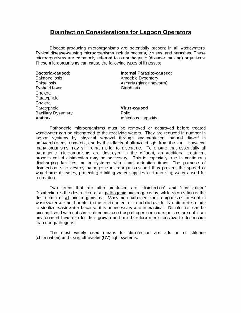
Disinfection Considerations for Lagoon Operators Disease-producing microorganisms are potentially present in all wastewaters. Typical disease-causing microorganisms include bacteria, viruses, and parasites. These microorganisms are commonly referred to as pathogenic (disease causing) organisms. These microorganisms can cause the following types of illnesses: Bacteria-caused: Internal Parasite-caused: Salmonellosis Amoebic Dysentery Shigellosis Ascaris (giant ringworm) Typhoid fever Giardiasis Cholera Paratyphoid Cholera Paratyphoid Virus-caused Bacillary Dysentery Polio Anthrax Infectious Hepatitis Pathogenic microorganisms must be removed or destroyed before treated wastewater can be discharged to the receiving waters. They are reduced in number in lagoon systems by physical removal through sedimentation, natural die-off in unfavorable environments, and by the effects of ultraviolet light from the sun. However, many organisms may still remain prior to discharge. To ensure that essentially all pathogenic microorganisms are destroyed in the effluent, an additional treatment process called disinfection may be necessary. This is especially true in continuous discharging facilities, or in systems with short detention times. The purpose of disinfection is to destroy pathogenic microorganisms and thus prevent the spread of waterborne diseases, protecting drinking water supplies and receiving waters used for recreation. Two terms that are often confused are “disinfection” and “sterilization.” Disinfection is the destruction of all pathogenic microorganisms, while sterilization is the destruction of all microorganisms. Many non-pathogenic microorganisms present in wastewater are not harmful to the environment or to public health. No attempt is made to sterilize wastewater because it is unnecessary and impractical. Disinfection can be accomplished with out sterilization because the pathogenic microorganisms are not in an environment favorable for their growth and are therefore more sensitive to destruction than non-pathogens.
The most widely used means for disinfection are addition of chlorine (chlorination) and using ultraviolet (UV) light systems.
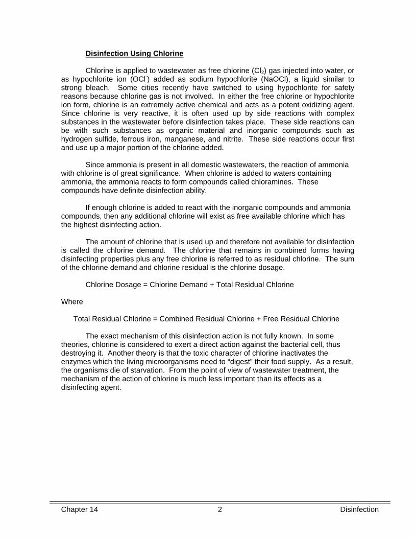
Disinfection Using Chlorine Chlorine is applied to wastewater as free chlorine (Cl2) gas injected into water, or as hypochlorite ion (OCl-) added as sodium hypochlorite (NaOCl), a liquid similar to strong bleach. Some cities recently have switched to using hypochlorite for safety reasons because chlorine gas is not involved. In either the free chlorine or hypochlorite ion form, chlorine is an extremely active chemical and acts as a potent oxidizing agent. Since chlorine is very reactive, it is often used up by side reactions with complex substances in the wastewater before disinfection takes place. These side reactions can be with such substances as organic material and inorganic compounds such as hydrogen sulfide, ferrous iron, manganese, and nitrite. These side reactions occur first and use up a major portion of the chlorine added. Since ammonia is present in all domestic wastewaters, the reaction of ammonia with chlorine is of great significance. When chlorine is added to waters containing ammonia, the ammonia reacts to form compounds called chloramines. These compounds have definite disinfection ability. If enough chlorine is added to react with the inorganic compounds and ammonia compounds, then any additional chlorine will exist as free available chlorine which has the highest disinfecting action. The amount of chlorine that is used up and therefore not available for disinfection is called the chlorine demand. The chlorine that remains in combined forms having disinfecting properties plus any free chlorine is referred to as residual chlorine. The sum of the chlorine demand and chlorine residual is the chlorine dosage. Chlorine Dosage = Chlorine Demand + Total Residual Chlorine Where Total Residual Chlorine = Combined Residual Chlorine + Free Residual Chlorine The exact mechanism of this disinfection action is not fully known. In some theories, chlorine is considered to exert a direct action against the bacterial cell, thus destroying it. Another theory is that the toxic character of chlorine inactivates the enzymes which the living microorganisms need to “digest” their food supply. As a result, the organisms die of starvation. From the point of view of wastewater treatment, the mechanism of the action of chlorine is much less important than its effects as a disinfecting agent.
Chapter 14 2 Disinfection
Both chlorine concentration and contact time are essential for effective killing of pathogenic microorganisms. Experimental determination of the best combination of combined residual chlorine and contact time is necessary to ensure both proper chlorine dose and minimum use of chlorine. Critical factors influencing disinfection are summarized as follows:
1. Injection point and method of mixing to get disinfectant in contact with wastewater being disinfected.
2. Design (shape) of contact chambers. Contact chambers are designed in
various sizes and shapes. Rectangular contact chambers often allow short-circulating and consequently reduced contact times. Baffles often are installed to increase mixing action, to obtain better distribution of disinfectant, and to reduce short-circulating which in turn increases contact time
3. Dose rate and type of chemical. Normally the higher the dose rate, the
quicker the disinfection rate. The form or type of chemical also influences the disinfection rate.
4. Contact time. With good initial mixing, the longer the contact time, the better
the disinfection. Most chlorine contact basins are designed to provide a contact time of about 30 minutes. In general, extending the chlorine contact time is more effective than increasing the chlorine dose to improve disinfection.
5. Effectiveness of upstream treatment processes. The lower the suspended
solids and organic content of the wastewater, the better the disinfection. Receiving waters such as streams, rivers, and lakes provide habitat for fish and numerous other types of aquatic organisms. The need for protection of this environment from toxic substances (such as chlorine) has prompted regulatory agencies to require very low chlorine residuals to be allowed to enter receiving waters in the effluents from wastewater treatment plants. These low concentrations are not effective for disinfection. Therefore treatment facilities using chlorine have to dose at higher levels and then remove the chlorine from the flow after disinfection. Removal of chlorine from treatment plant effluents is called dechlorination. This is commonly accomplished by the use of sulfur compounds such as sulfur dioxide, sodium sulfite, sodium bisulfite, or sodium metabisulfite.
Chapter 14 3 Disinfection
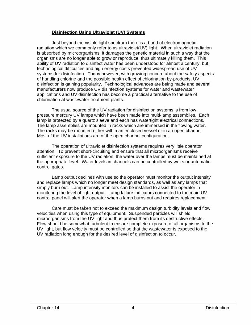
Disinfection Using Ultraviolet (UV) Systems
Just beyond the visible light spectrum there is a band of electromagnetic radiation which we commonly refer to as ultraviolet(UV) light. When ultraviolet radiation is absorbed by microorganisms, it damages the genetic material in such a way that the organisms are no longer able to grow or reproduce, thus ultimately killing them. This ability of UV radiation to disinfect water has been understood for almost a century, but technological difficulties and high energy costs prevented widespread use of UV systems for disinfection. Today however, with growing concern about the safety aspects of handling chlorine and the possible health effect of chlorination by-products, UV disinfection is gaining popularity. Technological advances are being made and several manufacturers now produce UV disinfection systems for water and wastewater applications and UV disinfection has become a practical alternative to the use of chlorination at wastewater treatment plants. The usual source of the UV radiation for disinfection systems is from low pressure mercury UV lamps which have been made into multi-lamp assemblies. Each lamp is protected by a quartz sleeve and each has watertight electrical connections. The lamp assemblies are mounted in racks which are immersed in the flowing water. The racks may be mounted either within an enclosed vessel or in an open channel. Most of the UV installations are of the open channel configuration. The operation of ultraviolet disinfection systems requires very little operator attention. To prevent short-circuiting and ensure that all microorganisms receive sufficient exposure to the UV radiation, the water over the lamps must be maintained at the appropriate level. Water levels in channels can be controlled by weirs or automatic control gates. Lamp output declines with use so the operator must monitor the output intensity and replace lamps which no longer meet design standards, as well as any lamps that simply burn out. Lamp intensity monitors can be installed to assist the operator in monitoring the level of light output. Lamp failure indicators connected to the main UV control panel will alert the operator when a lamp burns out and requires replacement. Care must be taken not to exceed the maximum design turbidity levels and flow velocities when using this type of equipment. Suspended particles will shield microorganisms from the UV light and thus protect them from its destructive effects. Flow should be somewhat turbulent to ensure complete exposure of all organisms to the UV light, but flow velocity must be controlled so that the wastewater is exposed to the UV radiation long enough for the desired level of disinfection to occur.
Chapter 14 4 Disinfection
Measuring Disinfection Effectiveness
The measurement of residual chlorine does supply a tool for practical control, however even a high chlorine residual is not a guarantee of effective bacteria destruction. Also, since ultraviolet rays leave no residual to measure, other means must be used to determine if disinfection was effective. The objective of disinfection is the destruction of pathogenic bacteria, and the ultimate measure of the effectiveness is the bacteriological result. However, it is not practical to measure all the types of pathogens that may be present. The microorganism population usually is estimated by determining the number of coliform group organisms present. Coliform bacteria are generally considered harmless, but their presence may be indicative of the presence of disease-producing organisms that may be found with them. This determination therefore does not test for individual pathogenic microorganisms, but uses the coliform group of organisms as the indicator organism. High coliform counts indicate possible presence of pathogens, while low numbers of coliform bacteria indicates that the disinfection was likely effective.
Coliform bacteria can be divided into fecal and non-fecal groups. Although coliform bacteria are found nearly everywhere in the environment, fecal coliform bacteria indicate the presence of bacteria originating from the intestines of war-blooded animals. These bacteria are then a better indication of the possible presence of pathogenic organisms. In Michigan, fecal coliform analysis is used to determine effectiveness of disinfection. Generally, disinfection is considered effective if the number of fecal coliform is less than 200 in 100 milliliters of effluent sample. Two methods are approved for coliform analysis. They are the Multiple Tube Fermentation Method and the Membrane Filter (MF) Method. The multiple tube coliform test has been a standard method for many years. In this procedure, tubes of a special nutrient broth are inoculated with dilutions of a wastewater or water sample. The coliform density is then calculated from statistical probability formulas that predict the most probable number (MPN) of coliform necessary to produce certain combinations of gas-positive and gas-negative tubes in the series of inoculated tubes. The Membrane Filter (MF) Method is the more commonly used method. The basic procedure involves filtering a known volume of water through a membrane filter of optimum pore size for full bacteria retention. As the water passes through the pores, bacteria are entrapped on the upper surface of the filter. The membrane filter is then placed in contact with a paper pad saturated with liquid medium to provide nutrients for bacteria growth. Following incubation under prescribed conditions of time, temperature, and humidity, the cultures are examined for coliform colonies that are counted and recorded as a density of coliform per 100 milliliters of water sample.
Chapter 14 5 Disinfection


Appendix

APPENDIX A
IMPORTANT NUMBERS FOR MICHIGAN
FACULTATIVE LAGOON OPERATORS

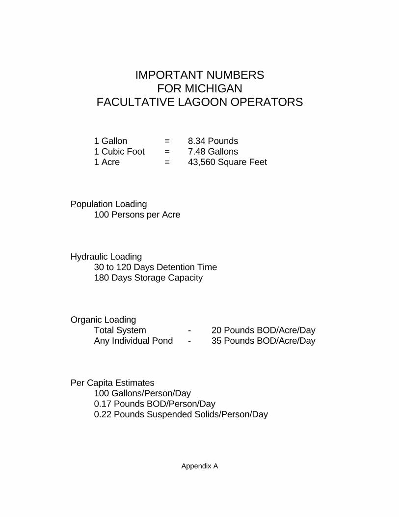
Appendix A
IMPORTANT NUMBERS FOR MICHIGAN FACULTATIVE LAGOON OPERATORS 1 Gallon = 8.34 Pounds 1 Cubic Foot = 7.48 Gallons 1 Acre = 43,560 Square Feet Population Loading 100 Persons per Acre Hydraulic Loading 30 to 120 Days Detention Time 180 Days Storage Capacity Organic Loading Total System - 20 Pounds BOD/Acre/Day Any Individual Pond - 35 Pounds BOD/Acre/Day Per Capita Estimates 100 Gallons/Person/Day 0.17 Pounds BOD/Person/Day 0.22 Pounds Suspended Solids/Person/Day


APPENDIX B
Common Conversion Factors And
Formulas

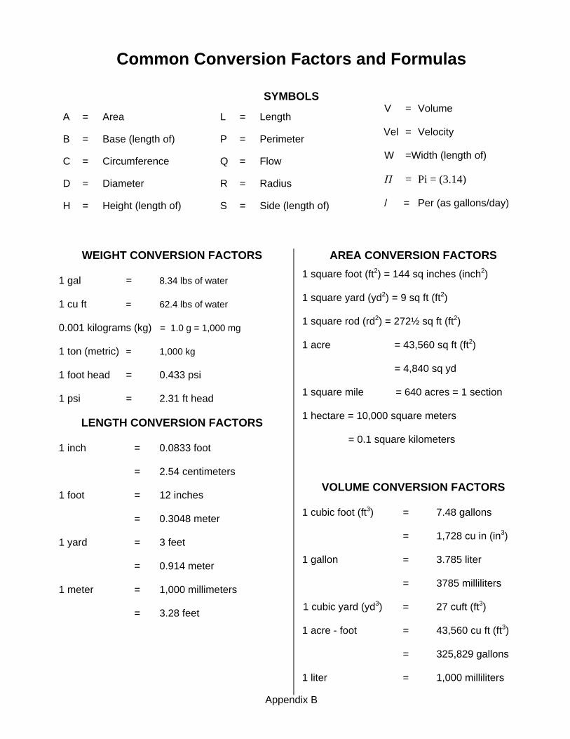
Common Conversion Factors and Formulas
SYMBOLS
A = Area
B = Base (length of)
C = Circumference
D = Diameter
H = Height (length of)
L = Length
P = Perimeter
Q = Flow
R = Radius
S = Side (length of)
V = Volume Vel = Velocity W =Width (length of) Π = Pi = (3.14) / = Per (as gallons/day)
WEIGHT CONVERSION FACTORS
1 gal = 8.34 lbs of water
1 cu ft = 62.4 lbs of water
0.001 kilograms (kg) = 1.0 g = 1,000 mg
1 ton (metric) = 1,000 kg
1 foot head = 0.433 psi
1 psi = 2.31 ft head
LENGTH CONVERSION FACTORS
1 inch = 0.0833 foot
= 2.54 centimeters
1 foot = 12 inches
= 0.3048 meter
1 yard = 3 feet
= 0.914 meter
1 meter = 1,000 millimeters
= 3.28 feet
AREA CONVERSION FACTORS 1 square foot (ft2) = 144 sq inches (inch2)
1 square yard (yd2) = 9 sq ft (ft2)
1 square rod (rd2) = 272½ sq ft (ft2)
1 acre = 43,560 sq ft (ft2)
= 4,840 sq yd
1 square mile = 640 acres = 1 section
1 hectare = 10,000 square meters
= 0.1 square kilometers
VOLUME CONVERSION FACTORS
1 cubic foot (ft3) = 7.48 gallons
= 1,728 cu in (in3)
1 gallon = 3.785 liter
= 3785 milliliters
1 cubic yard (yd3) = 27 cuft (ft3)
1 acre - foot = 43,560 cu ft (ft3)
= 325,829 gallons
Appendix B
1 liter = 1,000 milliliters
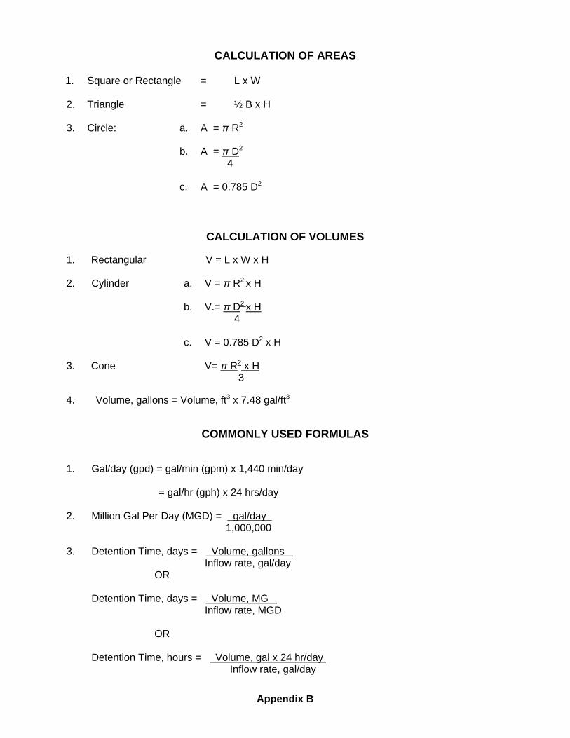
CALCULATION OF AREAS
1. Square or Rectangle = L x W
2. Triangle = ½ B x H
3. Circle: a. A = π R2
b. A = π D2
4
c. A = 0.785 D2
CALCULATION OF VOLUMES
1. Rectangular V = L x W x H
2. Cylinder a. V = π R2 x H
b. V.= π D2 x H 4
c. V = 0.785 D2 x H
3. Cone V= π R2 x H 3 4. Volume, gallons = Volume, ft3 x 7.48 gal/ft3
COMMONLY USED FORMULAS 1. Gal/day (gpd) = gal/min (gpm) x 1,440 min/day = gal/hr (gph) x 24 hrs/day 2. Million Gal Per Day (MGD) = gal/day . 1,000,000 3. Detention Time, days = Volume, gallons . Inflow rate, gal/day OR Detention Time, days = Volume, MG . Inflow rate, MGD OR Detention Time, hours = Volume, gal x 24 hr/day . Inflow rate, gal/day
Appendix B
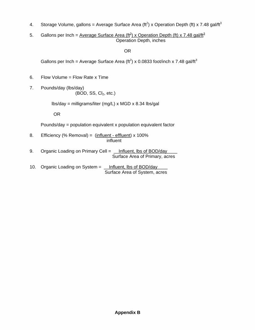
4. Storage Volume, gallons = Average Surface Area (ft2) x Operation Depth (ft) x 7.48 gal/ft3 5. Gallons per Inch = Average Surface Area (ft2) x Operation Depth (ft) x 7.48 gal/ft3 Operation Depth, inches
OR
Gallons per Inch = Average Surface Area (ft2) x 0.0833 foot/inch x 7.48 gal/ft3
6. Flow Volume = Flow Rate x Time 7. Pounds/day (lbs/day) (BOD, SS, Cl2, etc.) lbs/day = milligrams/liter (mg/L) x MGD x 8.34 lbs/gal OR Pounds/day = population equivalent x population equivalent factor 8. Efficiency (% Removal) = (influent - effluent) x 100% influent 9. Organic Loading on Primary Cell = Influent, lbs of BOD/day . Surface Area of Primary, acres 10. Organic Loading on System = Influent, lbs of BOD/day . Surface Area of System, acres
Appendix B

APPENDIX C
Partial List of Items to Include in Lagoon Facility Inspections

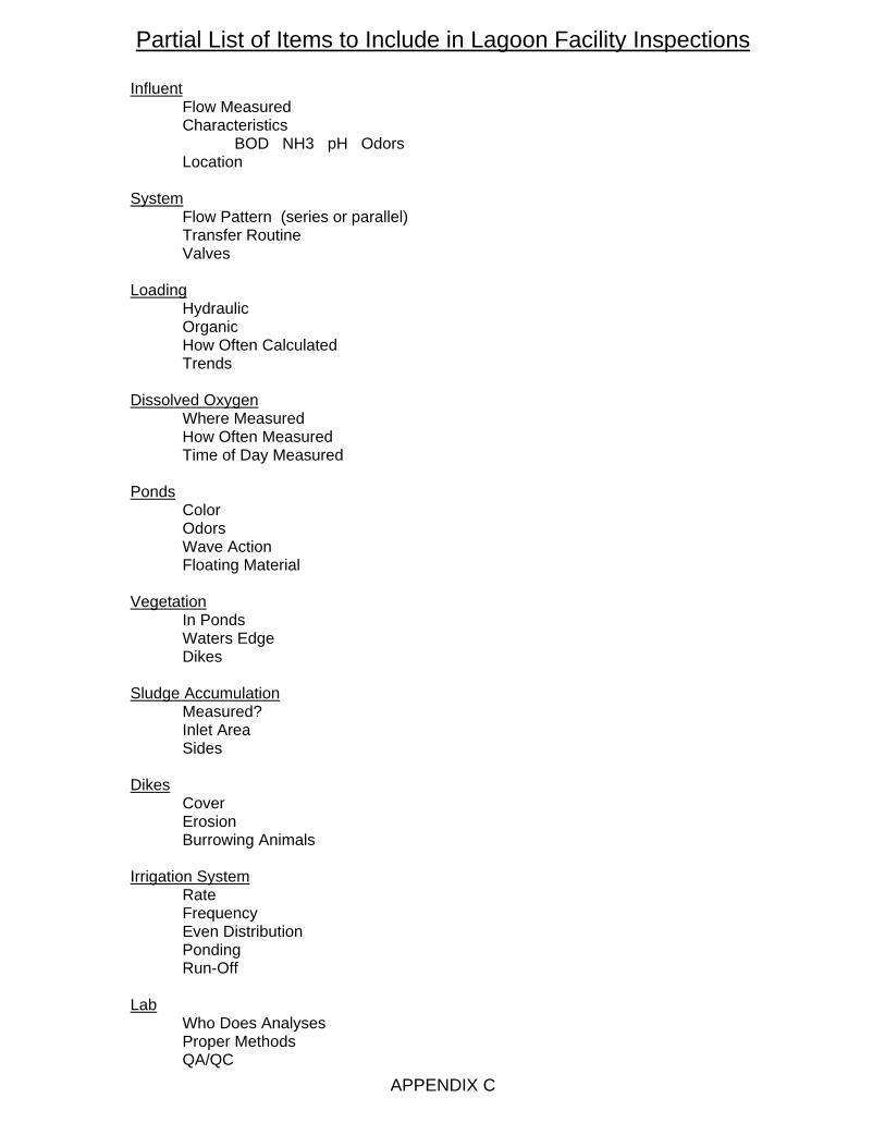
APPENDIX C
Partial List of Items to Include in Lagoon Facility Inspections Influent Flow Measured Characteristics BOD NH3 pH Odors Location System Flow Pattern (series or parallel) Transfer Routine Valves Loading Hydraulic Organic How Often Calculated Trends Dissolved Oxygen Where Measured How Often Measured Time of Day Measured Ponds Color Odors Wave Action Floating Material Vegetation In Ponds Waters Edge Dikes Sludge Accumulation Measured? Inlet Area Sides Dikes Cover Erosion Burrowing Animals Irrigation System Rate Frequency Even Distribution Ponding Run-Off Lab Who Does Analyses Proper Methods QA/QC

APPENDIX D
Example Operation and Maintenance Schedule

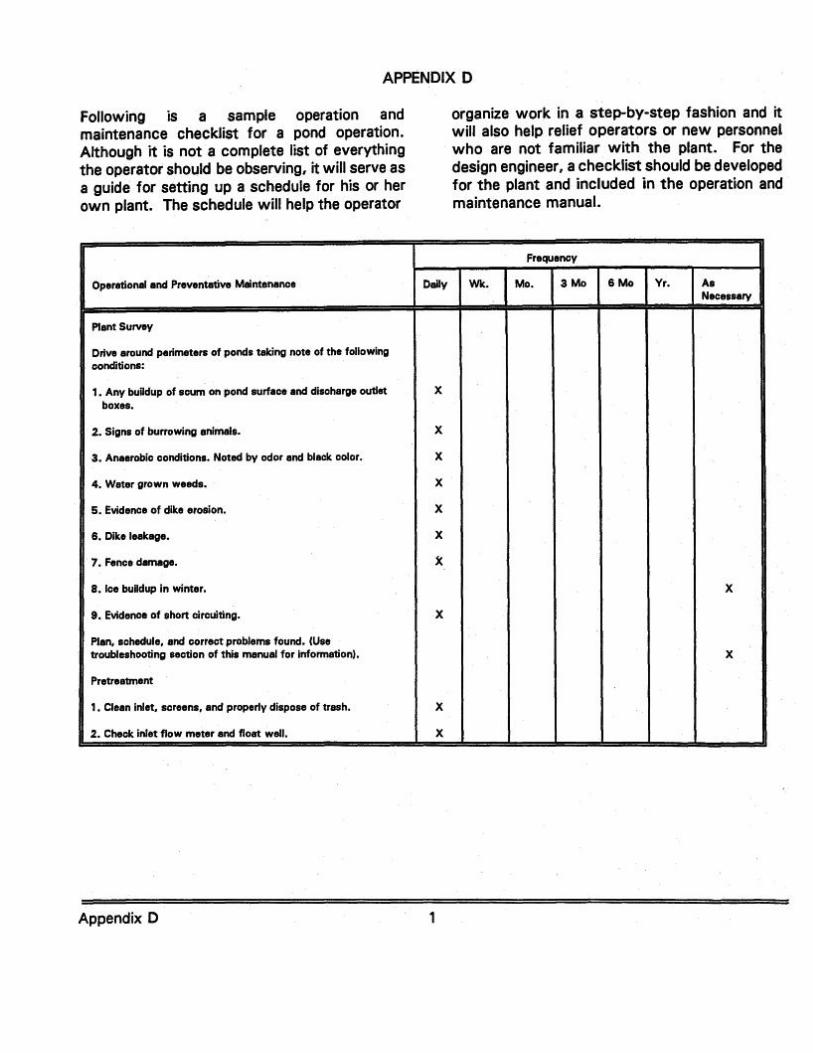

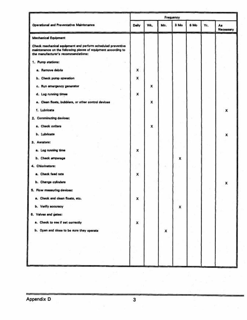

APPENDIX E
Example Operation and Maintenance Inspection
Checklist

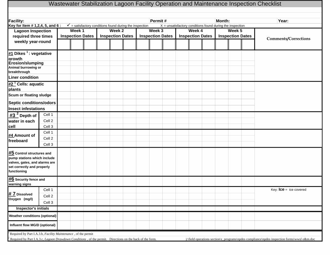
Cell 2Cell 3Cell 1Cell 2Cell 3
Cell 1
Cell 2
Cell 3
2 Required by Part I.A.3.c, Lagoon Drawdown Conditions , of the permit. Directions on the back of the form. j:\field operations section\z_programs\npdes compliance\npdes inspection forms\wwsl o&m.doc
Year: Month:Permit # Facility:
Key: Ice = ice covered
Week 5 Inspection Dates
#1 Dikes 1 : vegetative growth
Influent flow MG/D (optional)
1 Required by Part I.A.3.b, Facility Maintenance , of the permit
# 7 Dissolved Oxygen (mg/l)
#6 Security fence and warning signs
Inspector's initials
Wastewater Stabilization Lagoon Facility Operation and Maintenance Inspection Checklist
Comments/Corrections
Week 1 Inspection Dates
Lagoon Inspection required three times weekly year-round
Week 2 Inspection Dates
Week 3 Inspection Dates
Key for Item # 1,2,4, 5, and 6 : = satisfactory conditions found during the inspection X = unsatisfactory conditions found during the inspectionWeek 4
Inspection Dates
Septic conditions/odorsInsect infestations #3 2 Depth of water in each cell
Cell 1
Weather conditions (optional)
#4 Amount of freeboard
#5 Control structures and pump stations which include valves, gates, and alarms are set correctly and properly functioning
Scum or floating sludge
Erosion/slumpingAnimal burrowing or breakthroughLiner condition #2 1 Cells: aquatic plants
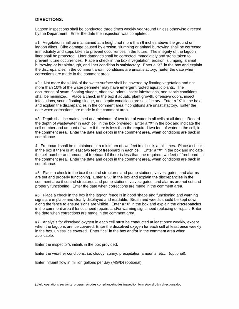
DIRECTIONS: Lagoon inspections shall be conducted three times weekly year-round unless otherwise directed by the Department. Enter the date the inspection was completed. #1: Vegetation shall be maintained at a height not more than 6 inches above the ground on lagoon dikes. Dike damage caused by erosion, slumping or animal burrowing shall be corrected immediately and steps taken to prevent occurrences in the future. The integrity of the lagoon liner shall be protected. Liner damages shall be corrected immediately and steps taken to prevent future occurrences. Place a check in the box if vegetation, erosion, slumping, animal burrowing or breakthrough, and liner condition is satisfactory. Enter a “X” in the box and explain the discrepancies in the comment area if conditions are unsatisfactory. Enter the date when corrections are made in the comment area. #2 : Not more than 10% of the water surface shall be covered by floating vegetation and not more than 10% of the water perimeter may have emergent rooted aquatic plants. The occurrence of scum, floating sludge, offensive odors, insect infestations, and septic conditions shall be minimized. Place a check in the box if aquatic plant growth, offensive odors, insect infestations, scum, floating sludge, and septic conditions are satisfactory. Enter a “X” in the box and explain the discrepancies in the comment area if conditions are unsatisfactory. Enter the date when corrections are made in the comment area. #3: Depth shall be maintained at a minimum of two feet of water in all cells at all times. Record the depth of wastewater in each cell in the box provided. Enter a “X” in the box and indicate the cell number and amount of water if there is less than the required two feet of water in the cell, in the comment area. Enter the date and depth in the comment area, when conditions are back in compliance. 4: Freeboard shall be maintained at a minimum of two feet in all cells at all times. Place a check in the box if there is at least two feet of freeboard in each cell. Enter a “X” in the box and indicate the cell number and amount of freeboard if there is less than the required two feet of freeboard, in the comment area. Enter the date and depth in the comment area, when conditions are back in compliance. #5: Place a check in the box if control structures and pump stations, valves, gates, and alarms are set and properly functioning. Enter a “X” in the box and explain the discrepancies in the comment area if control structures and pump stations, valves, gates, and alarms are not set and properly functioning. Enter the date when corrections are made in the comment area. #6: Place a check in the box if the lagoon fence is in good shape and functioning and warning signs are in place and clearly displayed and readable. Brush and weeds should be kept down along the fence to ensure signs are visible. Enter a “X” in the box and explain the discrepancies in the comment area if fences need repairs and/or warning signs need replacing or repair. Enter the date when corrections are made in the comment area. #7: Analysis for dissolved oxygen in each cell must be conducted at least once weekly, except when the lagoons are ice covered. Enter the dissolved oxygen for each cell at least once weekly in the box, unless ice covered. Enter “ice” in the box and/or in the comment area when applicable. Enter the inspector’s initials in the box provided. Enter the weather conditions, i.e. cloudy, sunny, precipitation amounts, etc… (optional). Enter influent flow in million gallons per day (MG/D) (optional). j:\field operations section\z_programs\npdes compliance\npdes inspection forms\wwsl o&m directions.doc

Glossary
════════════════════════════════════════ Glossary 1
ABSORPTION The taking up of one substance into the body of another by chemical or molecular action.
ACRE-FOOT A volume term referring to that amount of liquid, 1 acre
in area, one foot deep. (43,560 cubic feet). ADSORPTION The taking up of substance upon the surface or onto the
interface zone of another. AERATED POND A wastewater treatment pond in which mechanical or
diffused-air aeration is used to supplement the oxygen supply.
AEROBIC A condition characterized by the presence of free
dissolved oxygen in the aquatic environment. AEROBIC BACTERIA Bacteria that require free dissolved oxygen for growth. AEROBIC DECOMPOSITION The breakdown of complex organic matter by bacteria in
the presence of dissolved oxygen. ALGAE Primitive one or many-celled plants, usually aquatic, that
produce their food by photosynthesis. ALGAL BLOOM Large masses of microscopic and macroscopic plant
life, such as green algae, occurring in bodies of water. ALGICIDE Any substance or chemical applied to kill or control algal
growths. ANAEROBIC The condition in which dissolved oxygen is undetectable
in the aquatic environment. ANAEROBIC BACTERIA Bacteria which grow in the absence of free dissolved
oxygen and must obtain their oxygen by chemically breaking down organic compounds which contain combined oxygen.
AQUATIC VEGETATION That vegetation which will grow in or near water. BACTERIA A group of universally distributed microscopic organisms
lacking chlorophyll and utilizing organic nutrients as a food source.
BAR RACKS (SCREENS) A course screen usually consisting of bars, equally spaced to trap roots, branches, rags, and other large material that may be found in the wastewater flow.
════════════════════════════════════════ Glossary 2
BIOLOGICAL OXIDATION The process whereby living organisms in the presence of oxygen convert the organic matter in wastewater into a more stable or a mineral form.
BIOLOGY The science and study of living organisms, their
characteristics and behavior. BOD Biological or biochemical oxygen demand. A test for
estimation of wastewater polluting effects in terms of the oxygen requirements for biochemical stabilization under specified conditions of temperature and time.
CAVITATION The formation and collapse of a gas pocket or bubble on
the blade of an impeller. The collapse of this gas pocket or bubble drives water into the impeller with a terrific force that can cause pitting on the impeller surface.
CHEMOHETEROTROPHIC A process of bacterial cell growth in which the organism
utilizes the chemical energy derived from a breakdown of performed complex organic substances into essential nutrients.
CHEMISTRY A science that deals with the composition and
characteristics of substances and their behavior, i.e., transformations that they undergo.
CHLORINE An element having strong disinfecting and oxidizing
properties in moler solution. It is commercially available as compressed gas, liquid or in combined form as a powder. It is highly toxic and irritating to skin, eyes, and lungs in significant concentration.
CHLORINATION The application of chlorine to water or wastewater for
the purpose of disinfection, oxidation, odor control or other effects. Pre-chlorination before treatment; post chlorination - after treatment; in-process chlorination - during treatment.
CHLORINATION CHAMBER A basin or tank where chlorine is applied to the
wastewater.
════════════════════════════════════════ Glossary 3
COLIFORM GROUP A group of bacteria that inhabit the intestinal tract of man, warm blooded animals, and may be found in plants, soil, air and the aquatic environment. Includes aerobic and facultative gram negative non-spore forming bacilli that ferment lactose with gas formation.
COMMINUTOR A device used to reduce the size of the solid chunks in
wastewater by shredding (comminuting). The shredding action can be visualized if you imagine many scissors cutting or hammering to shreds all of the large solids in the wastewater.
DETENTION TIME The theoretical time required to displace the contents of
a tank or other treatment unit at a given rate of discharge.
DISCHARGE Any flow of effluent from a treatment unit. See effluent. DISCHARGE HEAD The pressure (in feet or pounds per square inch, psi) on
the discharge side of a pump. The pressure can be measured from the center line of the pump to the hydraulic grade line of the water in the discharge pipe.
DISINFECTION To make free of infectious organisms; to kill disease
organisms. DISSOLVED OXYGEN (DO) Dissolve molecular oxygen usually expressed in mg/L,
ppm or percent saturation. DIURNAL Having a daily cycle. DRY WELL A dry room or compartment in a lift station, near or
below the water level, where the pumps are located. DYNAMIC HEAD When a pump is operating, the vertical distance (in feet)
from a point to the energy grade lines. Also see TOTAL DYNAMIC HEAD and STATIC HEAD.
EFFLUENT A liquid flowing out of a chamber, treatment unit or
basin. ESCHERICHIA COLI A species of bacteria which are normal
inhabitants of the intestine of man and other warm blooded vertebrates. See FECAL COLIFORM BACTERIA.
════════════════════════════════════════ Glossary 4
FACULTATIVE BACTERIA Those bacteria that can adapt to aerobic or anaerobic conditions. Can utilize dissolved or combined oxygen.
FECAL COLIFORM BACTERIA Bacterial organisms present as a result of direct fecal
contamination. Those bacteria that normally inhabit the intestines of warm blooded vertebrates.
FORCE MAIN A pipe that conveys wastewater under pressure
from the discharge side of a pump to a point of gravity flow downstream.
FREEBOARD The vertical distance from the water level in a flume,
conduit, channel, basin or other water enclosure to the top of the confining structure.
FUNGI Simple or complex organisms without chlorophyll. The
simpler forms are one-celled; higher forms have branched filaments and complicated life cycles. Examples are molds, yeasts, and mushrooms.
GRAB SAMPLE A single sample not necessarily taken at a set time or
flow. An instantaneous sample. GRAVITY SYSTEM A system of open or closed conduits in which the liquid
flows by gravity (without pumping). GRIT The heavy material in water or sewage, such as sand,
gravel, cinders, etc. HEAD A term used to describe the height or energy of water
above a point. A head of water may be measured in either height (feet) or pressure (pounds per square inch, psi). Also see DISCHARGE HEAD, DYNAMIC HEAD, STATIC HEAD, SUCTION HEAD, SUCTION LIFT and VELOCITY HEAD.
INFILTRATION a). The entrance of ground water into a sewer through
breaks, defective joints or porous walls. b). The penetration of water through the soil from surface precipitation, stream or impoundment boundaries.
INFLOW Extraneous water entering a sanitary sewer system by
direct connection from roof drains, basement sumps, manhole covers, etc.
INFLUENT That material entering a process unit or operation.
════════════════════════════════════════ Glossary 5
INORGANIC MATTER Chemical substances of mineral origin, and not readily biodegradable.
IMPELLER A rotating set of vanes in a pump designed to pump or
lift water. LIFT STATION A wastewater pumping station that lifts the wastewater
to a higher elevation when the continuance of the sewer at reasonable slopes would involve excessive depths of trench, or that raises wastewater from areas too low to drain into available sewers. These stations may be equipped with air operated ejectors or centrifugal pumps. Sometimes called a "Pump Station". The term "Pump Station" is usually reserved for a similar type of facility that is discharging into a long "Force Main", while a lift station has a discharge line or force main only up to the downstream gravity sewer. Throughout this manual when we refer to lift stations, we intend to include pump stations.
LUBRIFLUSHING Where bearings are grease lubricated, remove relief
plug and apply proper lubricant to the bearing at the lubrication fitting. Run pump and expel excess lubricant.
MEAN DEPTHS The average depth of water in any enclosure. MICROBIOLOGY The science and study of microbiological organisms and
their behavior. Commonly related to the study of pathogenic organisms.
MILLI An expression used to indicate 1/1000 of a standard unit
of weight, length or capacity (metric system). milliliter (ml) 1/1000 liter (l) milligram (mg) 1/1000 gram (g) millimeter (mm) 1/1000 meter (m) MILLIGRAMS PER LITER (mg/L) A unit of concentration on a weight/volume basis,
milligrams per liter. Equivalent to ppm when the specific gravity of the liquid is 1.0.
MICROORGANISM Commonly an organism too small to be observed
individually by the human eye without optical aid. MINIMUM FLOW Those periods when wastewater flow is at its lowest
peak.
════════════════════════════════════════ Glossary 6
MPN (Most Probable Number): The number of bacterial organisms per unit volume which, in accordance with statistical theory, is most likely to yield the test result.
NITRIFICATION The biochemical conversion of unoxidized nitrogen
(ammonia and organic N) to oxidized nitrogen (usually nitrate).
NUTRIENTS a). Anything essential to support life. b). Includes many
common elements and combinations of them. The major nutrients include carbon, hydrogen, oxygen, nitrogen, sulfur, and phosphorus. c). Nitrogen and phosphorus are of major concern because they tend to recycle and are hard to separate because of solubility in water.
ORGANIC LOADING The number of pounds of BOD added to a treatment
unit per day. ORGANIC MATTER Chemical substances of animal and vegetable origin
basically of carbon structure. OUTFALL The outlet or channel through which wastewater effluent
is discharged. OXYGEN AVAILABLE That part of the oxygen available for aerobic
stabilization of organic matter. Includes dissolved oxygen and that available in nitrites or nitrates, peroxides, ozone and certain other forms of oxygen.
OXYGEN DEPLETION The loss of oxygen from water or wastewater due to
biological, chemical or physical action. PARASITIC BACTERIA Those bacteria which normally live off another living
organism known as the host. PARSHALL FLUME A calibrated device for measuring the flow of liquid in an
open conduit, consisting of a contracting length, a throat and an expanding length.
PARTS PER MILLION (ppm) A unit of concentration signifying parts of some
substance per million parts of dispersing medium on a weight basis. Equivalent numerically to mg/L only when the specific gravity of the mixture is 1.0. Example: 1 ppm = 1 pound of sugar in 1 million pounds of water (119,904 gallons)
════════════════════════════════════════ Glossary 7
PATHOGENIC ORGANISMS Bacterial, fungal, viral, or other organisms directly involved with diseases of plants, animals or man are included among this group.
PEAK FLOW The maximum quantity of flow that occurs over a
relatively short period of time. PERCENT REMOVAL The ratio expressed as a percentage of the material
removed from process water in terms of the material entering.
pH The logarithm of the reciprocal of the hydrogen ion
concentration; expresses the intensity of acidity or alkalinity.
PHOTOSYNTHESIS A process in which plants utilize sunlight and chlorophyll
to convert carbon dioxide and inorganic substances to oxygen and additional plant material.
PNEUMATIC EJECTOR A device for raising wastewater, sludge or other liquid
by alternately admitting it through an inward-swinging check valve into the bottom of an airtight pot and then discharging it through an outward-swinging check valve by admitting compressed air to the pot above the wastewater.
POLLUTION The addition of materials to water that produce harmful,
objectionable or nuisance effects in the water. A deterioration of water quality adversely affecting subsequent uses such as the addition of sewage, industrial wastes, heat, solids, etc. This term has varied definitions depending upon the situation and the objectives.
POPULATION EQUIVALENT a). The calculated population which would normally
contribute the same amount of biochemical oxygen demand (BOD per day). A common base is 0.17 lb. of 5-day BOD per capita per day. b). For an industrial waste, the estimated number of people contributing sewage equal in strength to a unit volume of the waste or to some other unit involved in producing or manufacturing a particular commodity.
PRE-AERATION Preliminary treatment of sewage comprising aeration to
remove gases, add oxygen, or promote flotation of grease, and aid coagulation.
════════════════════════════════════════ Glossary 8
PRELIMINARY TREATMENT Removal of rocks, rags, sand, and similar materials which may hinder the operation of a treatment plant. This is accomplished by using equipment such as bar screens, comminuters, and grit removal systems.
PRIMARY TREATMENT The first major unit in a treatment plant which utilizes
physical sedimentation to remove the greatest part of the suspended solids.
PUMP PIT A dry well, chamber or room below ground level in
which a pump is located. PUTREFACTION Biological decomposition of organic matter with the
production of ill-smelling products associated with anaerobic conditions.
RECORDER a). A device to keep a continuous or intermittent record
of some measured item such as flow, velocity, applied power, etc. b). An individual who tabulates or maintains records of events, actions, or measurements.
REDUCTION a). To make smaller or to remove from a given amount
of material. b). Chemistry - the removal of oxygen, addition of hydrogen or the addition of electrons to an element or compound. c). biology - to degrade complex organic materials.
REOXYGENATION The replenishing of dissolved oxygen. SALT A chemical compound formed as a result of the
interaction of an acid and an alkali (base). The commonest salt is sodium chloride.
SANITARY SEWER A sewer designed to receive and to convey household,
commercial or industrial wastewater mixtures. SECONDARY TREATMENT Commonly considered to include biochemical
degradation in addition to primary treatment or in place of it. Includes trickling filtration, activated sludge, stabilization ponds, etc.
SAPROPHYTIC ORGANISMS Organisms using dead or decaying organic matter as a
food source. SEPTIC WASTEWATER Wastewater in which available oxygen has been
depleted and the reduction of sulfates has begun. SETTLEABLE SOLIDS Those solids which will settle out when a sample of
════════════════════════════════════════ Glossary 9
sewage is allowed to stand quietly for one hour. SEWAGE Refers to the used water of a community. Generally
contaminated by the waste products from households, commercial or industrial activities. See WASTEWATER.
SEWER A pipe or conduit generally covered for the purposes of
conveying wastewaters from the point of origin to a point of treatment or discharge.
SEWERAGE SYSTEM A system of sewers and appurtenances for the
collection, transportation, pumping and treating of used waters.
SHOCK LOAD Refers to the situation where the influent contains waste
of a toxic nature, of very high organic content or when the pH either drops or rises drastically. Usually detrimental to the treatment process.
SHORT CIRCUITING The hydraulic conditions in a tank, chamber or basin
where time of passage is less than that of the normal flow-through period.
SLUDGE BANKS The accumulation of solids including silt, mineral,
organic and cell mass particulate material that is produced in an aquatic system.
SPRAY IRRIGATION A method of disposing of wastewater by
spreading it on land, usually from pipes equipped with spray nozzles.
STABILIZATION a). The activity proceeding along the pathway to
stability. b). In organic wastes, generally refers to oxidation via biochemical pathways and conversion to gaseous or insoluble materials relatively inert to further change.
STABILIZATION POND A secondary treatment mode in which natural
purification processes occur under controlled conditions. The interaction between algae and bacteria play a vital role in this process.
STANDARD METHODS Methods of analysis prescribed by joint action of the
APHA, AWWA, and WEA methods accepted by authority.
════════════════════════════════════════ Glossary 10
STATIC HEAD When water is not moving, the vertical distance (in feet) from a point at the water surface. Also see DYNAMIC HEAD.
STERILIZATION The destruction of all living organisms, ordinarily
through the agency of heat, chemicals or light. STILLING WELL A pipe, chamber, or compartment with a relatively small
inlet or inlets connected to a main body of water, such as water in a wet well. The purpose of a stilling well is to dampen waves or surges while allowing the water level within the well to rise and fall with the major fluctuations of the main body of water. It is used with water measuring flow and depth devices to improve the accuracy of measurement.
SUCTION HEAD The pressure (in feet or pounds per square inch, psi) on
the suction side of a pump. The pressure can be measured from the center line of the pump up to the elevation of the hydraulic grade on the suction side of the pump.
SUCTION LIFT The negative pressure (in feet or inches of mercury
vacuum) on the suction side of a pump. The pressure can be measured from the center line of the pump down to the elevation of the hydraulic grade line on the suction side of the pump.
SUPERSATURATION The situation in which water holds more oxygen at a
specified temperature than normally required for saturation at that temperature.
SUSPENDED SOLIDS The concentration of insoluble materials suspended or
dispersed in waste or used water generally expressed in mg/L on a dry weight basis usually determined by filtration methods.
TERTIARY TREATMENT Treatment in addition to normal or conventional
secondary methods. TITRATION The careful addition of a standard solution of known
concentration of reacting substance to an equivalence point to estimate the concentration of a desired material in a sample.
════════════════════════════════════════ Glossary 11
TOTAL DYNAMIC HEAD (TDH) When a pump is lifting or pumping water, the vertical distance (in feet) from the elevation of the energy grade line on the suction side of the pump to the elevation of the energy grade line on the discharge side of the pump.
TOTAL SOLIDS Refers to the solids contained in dissolved and
suspended form in water. Determined on weighing after drying at 103°C.
TOXIC A poison or acting like a poison. Something detrimental
to the treatment process, i.e., fuel oil, chromium salts, etc.
VELOCITY HEAD A vertical height (in feet) equal to the square of the
velocity of flowing water divided by twice the acceleration due to gravity (V2/2g).
VOLATILE SOLIDS The quantity of solids in water that represent a loss in
weight upon ignition at 550°C. VOLUTE The spiral-shaped casing surrounding a pump impeller
that collects the water discharged by the impeller. WASTEWATER Refers to the used water of a community. Generally
contaminated by the waste products from household, commercial or industrial activities. Often containing surface wash, storm water and infiltration waters.
WATER-BORNE DISEASE A disease caused by organisms or toxic substances
carried by water. The most common water-borne diseases are typhoid fever, asiatic cholera, polio, dysentery and other intestinal disturbances.
WEIR A device used for surface overflow from a tank, basin or
chamber. Generally designed to smooth out discharge flow to minimize turbulence within the detention basin. May be used to measure discharge flow.
WET WELL A compartment or room in which wastewater is
collected, and to which the suction pipe of a pump may be connected. Also a submersible pump may be located in a wet well.