Embed Size (px)
Citation preview
www.cartwright-consulting.com
United States Office European Office
8324 16th
Avenue South President Kennedylaan 94
Minneapolis, MN 55425-1742 2343 GT Oegstgeest
Phone: (952) 854-4911 The Netherlands
Fax: (952) 854-6964 Phone: 31-71-5154417
Wastewater Recovery
& Reuse – Part II
Presented at:
Saudi Arabia Water Environment Association
by
Peter S. Cartwright, PE
April 13-14, 2016
Cartwright Consulting Co., LLC

Saudi Arabia Water Environment Association – April 13-14, 2016 Page 2 Wastewater Recovery & Reuse – Part II Copyright – Peter S. Cartwright, PE
TABLE OF CONTENTS
Biological Wastewater Treatment
Aerobic
Anoxic
Anaerobic
Application of Biological Treatment Processes
Suspended Growth (Activated Sludge)
Attached Growth (Fixed Film)
Trickling Filters
Rotating Biological Contactors (RBCs)
Moving Bed Biofilm Reactors (MBBRs)
A Word of Caution
MBR
Introduction
History
MBR Technology
Introduction
Microfiltration
Ultrafiltration
MBR Process
Membrane Configuration
Plate & Frame
Hollow Fiber
Tubular
Membrane Materials
System Design
Introduction
System Components
Operating Considerations
Fouling
Cleaning
Myths and Realities
Conclusions

Saudi Arabia Water Environment Association – April 13-14, 2016 Page 3 Wastewater Recovery & Reuse – Part II Copyright – Peter S. Cartwright, PE
TABLE OF CONTENTS (Con’t.)
Disinfection
Introduction
Microorganism Categories
Bacteria
Protozoa
Viruses
Disinfection Technologies
Chemical Processes
Physical Removal
Legionnaires’ Disease
Controlling Legionella Bacteria
Standards
Glossary
Acronyms
Saudi Arabia Water Environment Association – April 13-14, 2016 Page 4 Wastewater Recovery & Reuse – Part II Copyright – Peter S. Cartwright, PE
BIOLOGICAL WASTEWATER TREATMENT
All biological-treatment processes take advantage of the remarkable ability of bacteria to use
diverse wastewater constituents to provide the energy for microbial metabolism and the building
blocks for cell synthesis. This metabolic activity, known as bioremediation, can remove the raw
materials, or break down almost all organic compounds.
A total bioremediation treatment process usually consists of the following stages:
Preliminary (Pretreatment) – Screening to remove bulky objects, grit and other large solids.
Primary Treatment – Clarification to allow suspended solids to settle out and oil to rise to the
surface.
Secondary Treatment – Biodegradation of biological contaminants utilizing technologies
described in this document.
Tertiary Treatment – Final filtration and/or disinfection, dictated by the ultimate use or discharge
of the treated effluent. This includes MBR, also detailed in this document.
In the secondary treatment stage of the total bioremediation process, the three types of biological
decomposition processes are known as aerobic, anoxic and anaerobic. They are described below.
Chemically, organic contaminants, BOD (Biochemical Oxygen Demand) and COD (Chemical
Oxygen Demand) are oxidized by losing an electron to an “acceptor.”
Aerobic
Dissolved molecular oxygen (O2) is the electron acceptor in this process. The end products are
primarily carbon dioxide (CO2), water and new cell material. This process is capable of breaking
down the widest spectrum of organic contaminants of all the decomposition processes. On the
other hand, it results in the largest production of new cells (activated sludge).
Aerobic digestion is very effective in the oxidation of ammonia (NH4+) to nitrite (NO2
-) and then
onto nitrate (NO3-). These particular microorganisms grow more slowly than those used to
consume BOD.
Aerobic decomposition is generally not suitable for high strength wastewaters (BOD >1000
mg/L); however, in certain small industrial applications, it may be capable of treating wastewater
with BOD concentrations as high as 3000 mg/L.
Anoxic
Microorganisms capable of using nitrate (NO3-) as the electron acceptor in the absence of oxygen
are utilized in the anoxic process. This is also employed for denitrification, the conversion of
nitrate to nitrogen gas (N2), and sludge production. Nitrate contamination of surface and ground
water supplies used in potable applications is a major issue today.

Saudi Arabia Water Environment Association – April 13-14, 2016 Page 5 Wastewater Recovery & Reuse – Part II Copyright – Peter S. Cartwright, PE
Anaerobic
This process dominates in waters without oxygen and nitrogen electron acceptors. It utilizes
sulfate (SO42-
), carbon dioxide (CO2) and organic compounds capable of accepting electrons.
The reduction of sulfate produces hydrogen sulfide (H2S) gas (odoriferous and explosive) as well
as organic sulfur compounds known as mercaptans. Methane (CH4) is also produced in the
anaerobic process. Sludge volume is low, and the flammable gases, particularly methane, can be
collected and used as a source of energy. Anaerobic digestion is most appropriate for wastewater
supplies with BOD concentrations above 1000 mg/L.
The following table compares anaerobic and aerobic bioremediation for treatment of wastewater
containing 1000 kg COD.
Parameters Anaerobic Aerobic
Power Requirements (kWhr) 1.5 65
Net Production of Biosolids (kg) 15-100 200-600
Useable Energy Produced (kWhr) 140 NiL

Saudi Arabia Water Environment Association – April 13-14, 2016 Page 6 Wastewater Recovery & Reuse – Part II Copyright – Peter S. Cartwright, PE
APPLICATION OF BIOLOGICAL TREATMENT PROCESSES
Suspended Growth (Activated Sludge)
This process involves air or oxygen being introduced into a mixture of primary treated or
screened municipal or industrial wastewater (referred to as “wastewater” from now on), reacting
with bacteria to develop a biological floc which reduces the organic content of the sewage. This
material (which in healthy sludge is a brown floc) is largely composed of saprotrophic bacteria
but also has an important protozoan flora mainly composed of amoebae, Spirotrichs, Peritichs,
including Vorticellids, and a range of other filter feeding species. Other important constituents
include motile and sedentary rotifers.
The combination of wastewater and biological mass is commonly known as mixed liquor. In a
typical activated sludge plant, once the wastewater has received sufficient microbial treatment,
excess mixed liquor is discharged into settling tanks and the treated supernatant is run off to
undergo further treatment before discharge. Part of the settled material, the sludge, is returned to
the head of the aeration system to re-seed the new wastewater entering the tank. The remainder is
discharged to the sludge handling system for treatment and disposal.
The solids retention time (SRT) is defined as the average amount of time that microorganisms
are kept in the system.
In conventional activated sludge systems, the wastewater is typically aerated for six to eight
hours. Sufficient air is provided to keep the sludge in suspension. The air is injected near the
bottom of the aeration tank through a system of diffusers. The volume of sludge returned to the
aeration basin is typically 20 to 30% of the wastewater flow.
The following list is an indication of the numerous configurations for the activated sludge
process, and these are illustration below.
Plug flow (conventional)
Step feed (step aeration)
Complete mix
Oxidation ditch
Sequencing batch reactor
Staged activated sludge
Contact stabilization
Conventional with selector

Saudi Arabia Water Environment Association – April 13-14, 2016 Page 7 Wastewater Recovery & Reuse – Part II Copyright – Peter S. Cartwright, PE
(Sources: Adapted from Rittmann and McCarty, 2001 and Metcalf & Eddy, 2003)
M.L. Davis, Water & Wastewater Engineering Design Principles & Practice (2010)

Saudi Arabia Water Environment Association – April 13-14, 2016 Page 8 Wastewater Recovery & Reuse – Part II Copyright – Peter S. Cartwright, PE
Attached Growth (Fixed Film)
In this process, the microorganisms attach themselves to inert media and generate a biofilm layer
(lipopolysaccharide). As the medium contains void spaces, air can circulate to allow oxygen to
contact the microorganisms for aerobic digestion. As layers of growth accumulate, they slough
off the media and form sludge in the bottom of the vessel.
The most common designs are trickling filters, rotating biological contactors (RBCs) and moving
bed biofilm reactors (MBBRs).
Trickling filters
Historically, these have utilized a 10 to 20 m diameter bed of stones, one to three m deep, with a
rotating arm to distribute the effluent over the surface. The stones range from 25 to 100 mm in
diameter, and provide the surface area necessary for the bacteria to establish biofilm and
metabolize the BOD. To provide for higher surface area and lower weight (to allow taller
systems – up to 12 m), plastic media, with a choice of many shapes and materials, are now
usually employed.
Most designs provide for the recirculation of a portion of the treated effluent back through the
filter.
Below is an illustration of two-stage trickling filter plant utilizing both synthetic media and rock
media.
(Sources: M.L. Davis, Water & Wastewater Engineering Design Principles & Practice (2010)

Saudi Arabia Water Environment Association – April 13-14, 2016 Page 9 Wastewater Recovery & Reuse – Part II Copyright – Peter S. Cartwright, PE
Rotating Biological Contactors (RBCs)
RBCs consist of a series of vertical disks about three meters in diameter and all mounted on a
horizontal shaft positioned near the top of the tank containing the effluent to be treated. Roughly
one half of the disks are immersed in the effluent, and they are slowly rotated to allow the
attached microorganisms to be alternatively exposed to the wastewater and the air. The biofilm
is one to three mm thick and excess growth sloughs off into the tank.
An illustration of the RBC process is below.
Moving Bed Biofilm Reactor (MBBRs)
These systems utilize small plastic elements (7-22 mm diameter) loosely contained in the reactor
tank. Air is usually directed into the tank from below and agitates the suspended growth.
Mechanical mixers may also be employed. The tank contains a screen to contain the media.
The following table compares these fixed film designs with activated sludge technology.

Saudi Arabia Water Environment Association – April 13-14, 2016 Page 10 Wastewater Recovery & Reuse – Part II Copyright – Peter S. Cartwright, PE
A Word of Caution
Knowing the composition of the wastewater is essential for planning a treatment process. In
petroleum refineries, for example, excessive amounts of spent caustic can quickly overwhelm a
wastewater treatment system due to the normally high COD of the caustic. Another issue can be
a significant increase in ammonia and sulfide loads that result from upsets in the operation of
sour-water strippers. These loads can, in turn, upset the biological treatment system if it is not
designed to handle ammonia and sulfide.
In addition to understanding the source and composition of the wastewater, it is important to
recognize when pretreatment steps are needed to provide adequate protection for a biological
treatment system. In most petroleum and petrochemical facilities, for example, raw wastewater
normally contains free oil, which can have serious, detrimental effects. Oil can coat and kill
bacteria, causing a drop in microbial activity, and can interfere with oxygen-transfer efficiency.
Another cause for concern in refineries is the potential upset in desalter operations that can lead
to oil/water emulsions in the wastewater and thereby negatively impact the biological treatment
system. To prevent these types of problems, process steps prior to biological treatment are
normally included. Pretreatment for this industry typically includes the use of oil/water
separators, and an equalization tank to mediate spikes in wastewater composition.
SUSPENDED
GROWTH
Activated Sludge Trickling Filter RBC MBBR
Requires residual
suspended solids
(MLSS)
No residual.
Suspended solids
returned.
No residual
suspended solids
returned
No residual
suspended solids
returned
Operator adjusts
MLSS levels
Self regulating, no
operator
adjustments
Self regulating, no
operator
adjustments
Self regulating, no
operator
adjustments
MLSS sludge
recycled back
through plant
Single pass flow
through
Single pass flow
through
Single pass flow
through
MLSS can be
flushed out with
high flows
Not affected by
high flows
Biology stripped of
media with high
flows
Not affected by
high flows
Moderate
mechanical
equipment
Low mechanical
equipment
High mechanical
equipment
Low mechanical
equipment
Unstable nutrient
removal
Stable nutrient
removal
Unstable nutrient
removal
Stable nutrient
removal
FIXED FILM

Saudi Arabia Water Environment Association – April 13-14, 2016 Page 11 Wastewater Recovery & Reuse – Part II Copyright – Peter S. Cartwright, PE
Even properly pretreated wastewater can still contain a wide variety of compounds which may or
may not be biodegradable. There may also be a significant concentration of compounds that
require modifications to the treatment process in order to meet discharge regulations. The types
of compounds present, the concentration of each and the ultimate discharge requirements are key
to selecting the proper biological treatment system. This is true whether the wastewater is being
discharged directly to the environment or to a publicly owned treatment works (POTW), or if it
is to be reused within the facility.
MBR
Introduction
With regard to bioremediation wastewater reuse, the most widely used technology is MBR
(Membrane Bioreactor).
Municipal wastewater treatment plants are designed to accept wastewater from all sources:
residences, commercial establishments, institutions and industrial plants. Generally known as
POTW (Publically Owned Treatment Works), they are usually located in or near a municipality,
city or town.
In addition to municipal sewage, this discussion also addresses industrial facilities that produce
wastewater high in biodegradable organic compounds (BOD).
Likewise, as septic systems utilize the same bioremediation process as municipal wastewater
plants, this discussion applies to these “decentralized” applications.
MBR is particularly unique because it combines one of the newest technologies, crossflow
pressure-driven membrane separation, with the oldest wastewater treatment technology,
biological degradation (bioremediation).
MBR technology normally utilizes activated sludge treatment as the bioremediation process and
membranes to “dewater” the biological sludge and produce a permeate (treated effluent) stream
with very low BOD and COD, and almost no particles (TSS) and bacteria. The membrane
basically replaces the final clarifier used in conventional activated sludge treatment, which
achieve solids separation by gravity only. The physical barrier imposed by the membrane
system accomplishes this removal. MBR also enables operation at higher sludge concentrations,
thereby reducing the required footprint and/or sludge production.
Some estimates indicate that MBR is growing at a rate of 25% per year. When considering the
huge number of bioremediation applications and current emphasis on wastewater recovery and
reuse, this figure is not unrealistic.
Saudi Arabia Water Environment Association – April 13-14, 2016 Page 12 Wastewater Recovery & Reuse – Part II Copyright – Peter S. Cartwright, PE
MBR applications include:
Residential development projects
Single dwellings
Housing clusters
Apartment buildings/condominiums
Commercial projects
Mining camps and other remote installations
Emergency response installations
Military installations
Sports facilities
Recreation parks
Schools
Shopping centers
Office parks
Industrial plants
Food processing
Abattoir facilities
Animal feed lots
The following chart illustrates the sizes of various water contaminants and treatment
technologies employed to remove them.

Saudi Arabia Water Environment Association – April 13-14, 2016 Page 13 Wastewater Recovery & Reuse – Part II Copyright – Peter S. Cartwright, PE
Water Contaminants, Sizes and Treatment Technologies

Saudi Arabia Water Environment Association – April 13-14, 2016 Page 14 Wastewater Recovery & Reuse – Part II Copyright – Peter S. Cartwright, PE
History
The MBR process was introduced in the late 1960s, as commercial scale microfiltration and
ultrafiltration membranes became available. The original process was introduced by Dorr-
Oliver, Inc. and combined the use of an activated sludge bioreactor with an external crossflow
membrane filtration loop. The flat sheet membranes used in this process were polymeric and
featured pore sizes ranging from 0.003 to 0.01µ. Due to the poor economics of the first
generation MBRs, they only found applications in niche areas with special needs, such as
isolated trailer parks or ski resorts.
The breakthrough for MBR came in 1989 with the idea of Yamamoto and co-workers in Japan to
submerge the membranes in the bioreactor. Until then, MBRs were designed with the membrane
device located external to the reactor (sidestream MBR) and relied on high transmembrane
pressures (TMP) to maintain filtration. With the membrane immersed into the bioreactor,
submerged MBR systems are usually preferred to the external configuration, especially for
municipal sewage treatment. The submerged configuration relies on bubble aeration to produce
mixing and limit fouling. The energy of the submerged system can be up to 2 orders of
magnitude lower than that of the sidestream systems, but submerged systems operate at lower
flux, requiring more membrane area. Aeration maintains solids in suspension, scours the
membrane surface and provides oxygen to the biomass, leading to improved biodegradability.
The lower operating cost provided by the submerged configuration along with the steady
decrease in membrane cost has resulted in a significant increase in MBR plant installations from
the mid 90s. Since then, further improvements in the MBR design and operation have been
introduced and incorporated into larger plants. While early MBRs were operated at solids
retention times (STR) as high as 100 days and with mixed liquor suspended solids (MLSS) levels
up to 30 g/L, the recent trend is to apply lower solids retention times (around 10-20 days),
resulting in more manageable MLSS levels (10-15g/L). Thanks to these new operating
conditions, the oxygen transfer and pumping costs have tended to decrease and overall
maintenance has been simplified. Typical hydraulic retention times (HRT) range between 3 and
10 hours. In terms of membrane configurations, hollow fiber and flat sheet membranes are
utilized in most MBR applications; however, tubular and even spiral wound device
configurations are being used to a limited extent.
The following table compares several of the processes with MBR in a number of parameters.

Saudi Arabia Water Environment Association – April 13-14, 2016 Page 15 Wastewater Recovery & Reuse – Part II Copyright – Peter S. Cartwright, PE
Biological Treatment Processes
Evaluation ParameterActivated
Sludge
Trickling
Filter
Rotating
Biological
Contractor
(RBC)
Membrane
Bioreactor
(MBR)
Effective BOD Removal x x
Effective COD Removal x x
Low O&M Costs x
Low Sludge Production x x x
Low Sludge Disposal Costs x x x
Good Operability: Winter x x
Good Operability: Summer x x x x
Good Performance: High Water
Temperature x x
Good Performance: Low Water
Temperature x x
Minimal Operator Attention x
Quick Upset Recovery x x x
Easy Expandability x
Efficient Nitrification x x
Easy Installation x
Energy Efficient x x
Minimal Space Requirements x x
Comparisons are made based on wastewater with a COD of 600 mg/L and BOD of 250 mg/L

Saudi Arabia Water Environment Association – April 13-14, 2016 Page 16 Wastewater Recovery & Reuse – Part II Copyright – Peter S. Cartwright, PE
MBR TECHNOLOGY
Introduction
MBR involves the utilization of either microfiltration (MF) or ultrafiltration (UF) membrane
technology to treat the water from or in a bioremediation tank to continuously remove TSS (total
suspended solids), BOD, COD and bacteria. This treated water then can be used in many non-
critical applications, or can be “polished” by reverse osmosis or other deionization processes,
followed by disinfection.
Membrane separation technologies have been around for about 60 years. These technologies
utilize a membrane to separate contaminants from water streams and are based on the
engineering principle of “crossflow filtration.” The illustration below compares the crossflow
mechanism with conventional filtration.
Microfiltration (MF)
The following figure depicts the mechanism of microfiltration. Generally, microfiltration
involves the removal of suspended materials ranging in size from approximately 0.01 to 1
microns (100 to 10,000 angstroms).
Microfiltration

Saudi Arabia Water Environment Association – April 13-14, 2016 Page 17 Wastewater Recovery & Reuse – Part II Copyright – Peter S. Cartwright, PE
Ultrafiltration (UF)
The illustration below depicts ultrafiltration, which is used to separate materials typically smaller
than 0.01 microns (100 angstroms). The removal characteristics of UF membranes can be
described in terms of "molecular weight cutoff" (MWCO), the maximum molecular weight of
compounds that will pass through the membrane pores. MWCO terminology is expressed in
Daltons. Basically, ultrafiltration is used to remove dissolved, non-ionic contaminants while
suspended solids are removed by microfiltration.
Ultrafiltration

Saudi Arabia Water Environment Association – April 13-14, 2016 Page 18 Wastewater Recovery & Reuse – Part II Copyright – Peter S. Cartwright, PE
MBR PROCESS
Introduction
The wastewater is pumped against a membrane surface. The membrane is selected to hold back
suspended solids, microorganisms such as bacteria and a high percentage of BOD and COD,
while allowing water to pass through.
The following illustration depicts the MBR process.
MBR Process
Below, typical aerobic activated sludge and MBR processes are illustrated.

Saudi Arabia Water Environment Association – April 13-14, 2016 Page 19 Wastewater Recovery & Reuse – Part II Copyright – Peter S. Cartwright, PE
MBR Advantages (over traditional bioremediation processes)
High-quality effluent, almost free from suspended solids
The ability to disinfect without the need for chemicals
Complete independent control of HRT (Hydraulic Retention Time) and SRT (Sludge
Retention Time), which allow more complete reduction of BOD and COD, and improved
stability of such processes as nitrification
Reduced sludge production
Process intensification through high biomass concentrations with MLSS (Mixed Liquor
Suspended Solids) over 25,000 mg/L
Ability to treat high strength wastes
More compact systems, resulting in a smaller footprint
Process unaffected by solids settling
Longer retention time for more complete nitrification
Reduction in post treatment disinfection requirements
MBR Disadvantages
Higher capital cost, primarily resulting from the membrane unit and pump costs
Higher operating costs associated with the energy requirements of the air blower and
pump
Operation at high SRTs may increase levels of inorganic chemicals that are harmful
to the microbial populations

Saudi Arabia Water Environment Association – April 13-14, 2016 Page 20 Wastewater Recovery & Reuse – Part II Copyright – Peter S. Cartwright, PE
Membrane Configurations
The two most common types of membranes used in the MBR process are plate and frame and
hollow fiber configurations.
Plate & Frame
In the plate and frame design, the permeate is drawn perpendicularly through the membrane
sheet. The panel between the membrane sheets is grooved to channel the permeate flow to an
opening at the top of the panel or to an integral pipe between panels.
Plate & Frame Element

Saudi Arabia Water Environment Association – April 13-14, 2016 Page 21 Wastewater Recovery & Reuse – Part II Copyright – Peter S. Cartwright, PE
There are significant variations exist between the different plate and frame membrane suppliers.
These include:
Panel size
Panel material
Membrane material
Pore size
Operating pressure
Membrane to panel attachment method
Hollow Fiber MBR Hollow fiber membranes are long, small diameter strands of a hollow fiber polymer, often coated
with a protective coating. These products are manufactured by an extrusion or spinneret process
rather than the coating process used for the other membrane configurations. The strands are
usually bundled and secured at the top and bottom when submerged in the activated sludge tank.
The permeate is drawn through the membrane wall into the center of the strand, and then travels
to one or both ends before discharging to the main permeate header.
A hollow fiber element is illustrated below.
Hollow Fiber Element
Variations between hollow fiber manufacturers include the following:
Fiber diameter
Method used to bundle the strands
Number of strands per bundle
Membrane material
The method in which air is applied to the bundle
Wall thickness

Saudi Arabia Water Environment Association – April 13-14, 2016 Page 22 Wastewater Recovery & Reuse – Part II Copyright – Peter S. Cartwright, PE
There are a number of types of bundles available, as described below:
U shaped bundle:
It contains one or several bundles of fibers in a ‘U’ configuration, and potted together at the
bottom of the module. This arrangement is only possible with small diameter and deformable
fibers.
U-Shaped Bundle
Saudi Arabia Water Environment Association – April 13-14, 2016 Page 23 Wastewater Recovery & Reuse – Part II Copyright – Peter S. Cartwright, PE
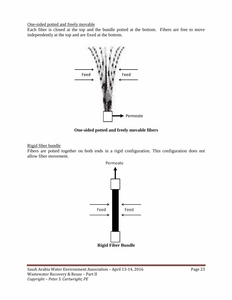
One-sided potted and freely movable
Each fiber is closed at the top and the bundle potted at the bottom. Fibers are free to move
independently at the top and are fixed at the bottom.
One-sided potted and freely movable fibers
Rigid fiber bundle
Fibers are potted together on both ends in a rigid configuration. This configuration does not
allow fiber movement.
Rigid Fiber Bundle

Saudi Arabia Water Environment Association – April 13-14, 2016 Page 24 Wastewater Recovery & Reuse – Part II Copyright – Peter S. Cartwright, PE
Both ends potted, flexible bundle
These bundles have the same configuration as the previous one, but the fibers are not rigid. In
this case, fibers are more free to move in between the two fixation points.
Both ends potted, flexible bundle
Tubular Elements
Manufactured from ceramic, carbon, stainless steel, or a number of thermoplastics, these tubes
have inside diameters ranging from ¼ inch up to approximately 1 inch (6 to 25 mm). The
membrane is typically coated on the inside of the tube and the feed solution flows under pressure
through the interior (lumen) from one end to the other, with the permeate passing through the
wall and collected outside of the tube. Tubular elements are illustrated below.
Tubular Membrane Element

Saudi Arabia Water Environment Association – April 13-14, 2016 Page 25 Wastewater Recovery & Reuse – Part II Copyright – Peter S. Cartwright, PE
This configuration is almost exclusively used only in external systems, as described below.
Spiral Elements
Spiral membranes can be immersed in the treatment tank, but have been only rarely used to date.
Spiral Wound Element

Saudi Arabia Water Environment Association – April 13-14, 2016 Page 26 Wastewater Recovery & Reuse – Part II Copyright – Peter S. Cartwright, PE
Membrane Materials
Typical MF and UF membrane polymer materials are listed in the table below.
Hollow Fiber Tubular Plate & Frame Spiral Wound
Polymeric
PS X X X X
PES X X X X
PAN X X X X
PE ─ X ─ ─
PP X X X ─
PVC ─ X ─ ─
PVDF X X ─ ─
PTFE X ─ X ─
PVP X X ─ ─
CA X ─ ─ ─
Non-Polymeric
Coated 316LSS ─ X ─ ─
a- Alumina ─ X X ─
Titanium Dioxide ─ X ─ ─
Silicon Dioxide ─ X ─ ─
PS = Polysulfone PVDF = Polyvinylidene Fluoride
PES = Polyethersulfone PTFE = Polytetrafluoroethylene
PE = Polyethylene CA = Cellulose Acetate
PP = Polypropylene PVP = Polyvinylpyrrolidone
PAN = Polyacrylonitrile TF = Thin Film Composite
Device ConfigurationMaterials of
Construction
Microfiltration (MF) & Ultrafiltration (UF)

Saudi Arabia Water Environment Association – April 13-14, 2016 Page 27 Wastewater Recovery & Reuse – Part II Copyright – Peter S. Cartwright, PE
SYSTEM DESIGN
Introduction
The following table is a very general comparison of the most widely used MBR membrane
configurations:
The most common biological treatment is aerobic and, typically, air is bubbled into the treatment
tank to encourage bacterial growth. As noted earlier, the membrane elements are usually
immersed vertically in the treatment tank and either the hydrostatic head of the solution or a
vacuum pump provides the pressure to force the permeate through the membrane. In the aerobic
process, air bubbles are also directed from below up across the surface of the membrane (air
scouring) in an effort to reduce fouling.
Another design involves pumping wastewater through the membrane system external to the
treatment tank (sidestream design). The membrane configuration normally used for this is the
tubular membrane element, in a “lumen feed” (inside-out) mode. To minimize fouling, the
wastewater is usually fed into the membrane at a high velocity, resulting in relatively high
energy consumption.
Yet another approach uses a separate tank for membrane processing downstream of the
biological treatment tank. Additional designs and configurations are sure to appear as MBR
technology becomes more widely used.
The following figures illustrate aerobic MBR applications for both “immersed” and “external”
designs.
Parameter Plate and Frame Hollow Fiber Tubular
Packing Density * Moderate High Low
Fouling Resistance Moderate Moderate High
Energy Requirement Moderate Low High
Backwashable No Yes Yes
Cleaning Ease Moderate Moderate Easy
Net Flux Range (L/m2/hr) 15-25 20-30 70-200
MLSS (mg/L) 10,000-15,000 10,000-15,000 10,000-30,000
* Membrane area per total element volume
Membrane Element Configuration

Saudi Arabia Water Environment Association – April 13-14, 2016 Page 28 Wastewater Recovery & Reuse – Part II Copyright – Peter S. Cartwright, PE
The table below compares the immersed with the external system design for several important
parameters. This comparison is very generalized, and the data may vary, based on the specific
system design.
Parameters Immersed External
Aeration Cost High Low
Pumping Cost Low High
Membrane Flux Low High
Cleaning Frequency Low High
Total Operating Cost Low High
Total Capital Cost High Low

Saudi Arabia Water Environment Association – April 13-14, 2016 Page 29 Wastewater Recovery & Reuse – Part II Copyright – Peter S. Cartwright, PE
System Components
A typical MBR System consists of the following main components:
Fine screen
Membrane cassettes containing elements
Bioremediation tank(s)
Permeate or feed pump
Blowers with diffusers
CIP (clean-in-place) system
Backwashing/Backpulsing equipment
This system may be represented by the following schematic, illustrating the immersed MBR
design in a separate treatment tank.

Saudi Arabia Water Environment Association – April 13-14, 2016 Page 30 Wastewater Recovery & Reuse – Part II Copyright – Peter S. Cartwright, PE
OPERATING CONSIDERATIONS
Fouling
Illustration of Membrane Fouling
The performance of an MBR system inevitably decreases over time, resulting from the
deposition of particulate materials from the activated sludge onto and into the membrane surface
(fouling).
As with other membrane separation processes, fouling is the most significant problem affecting
system performance. Fouling leads to an increase in hydraulic resistance, resulting in flux
decline or transmembrane pressure (TMP) increase.
The suspended biomass has no fixed composition and varies both with feed water composition
and MBR operating conditions. As a result, membrane fouling is extremely difficult to predict
and prevent.
Frequent membrane cleaning or replacement is therefore required, increasing the operating costs
significantly.

Saudi Arabia Water Environment Association – April 13-14, 2016 Page 31 Wastewater Recovery & Reuse – Part II Copyright – Peter S. Cartwright, PE
MBR performance can be influenced by interactions between the membrane system, the
biological fluid and its composition, and the filtration operating parameters. This is illustrated
below:
Factors influencing membrane fouling in MBR processes
In most municipal wastewater applications, non-biodegradable solids such as fibers, hair,
plastics, rags and other trash, present potential fouling problems. Hair and fibers tend to bind
with the biomass and create a reinforced plug that is usually removed by the 1 to 3 mm screens
located in front of the membranes. Hair can present real problems with hollow fibers by winding
around them, and, in some cases, breaking fibers.
Fouling can also be attributed to too much air scouring as well as over feeding antifouling or
flocculating chemicals.
Industrial applications, such as food processing, may introduce other types of foulants such as
fats, oil and grease (FOG), which require pretreatment ahead of MBR system.

Saudi Arabia Water Environment Association – April 13-14, 2016 Page 32 Wastewater Recovery & Reuse – Part II Copyright – Peter S. Cartwright, PE
Many anti-fouling strategies can be applied to MBR applications, including:
Relaxing, where filtration is stopped at regular time intervals for a couple of minutes
before being resumed. Particles deposited on the membrane surface tend to release back
into the tank, with the aid of continuous aeration applied during the resting period.
Membrane backwashing, where permeate water is pumped backwards into the
membrane, and flows through the pores to the feed channel, dislodging fouling materials.
Backwashing may be automatic, in intervals such as 10 minutes of run time, one minute
backwash, etc.
Air backpulsing where pressurized air on the permeate side of the membrane is released
as a pulse. This is directed through the permeate lines back through the membrane, as
with backwashing.
Cleaning
Examples of chemical cleaning include:
Chemically enhanced backwash (daily);
Maintenance cleaning with higher chemical concentration (weekly);
Intensive chemical cleaning (once or twice a year).
Intensive cleaning is carried out when filtration process cannot be sustained because of an
elevated transmembrane pressure (TMP). Each MBR manufacturer has proprietary chemical
recipes. Under normal conditions, the prevalent cleaning agents are NaOCl (sodium
hypochlorite) and citric acid. It is common for MBR suppliers to adapt specific protocols for
chemical cleanings (i.e. chemical concentrations and cleaning frequencies) for individual
facilities.
Following is a representative list of cleaning chemicals utilized by some manufacturers.
Agent Chemical Formula/Notation Concentration
Detergent Sodium hypochlorite NaOCl 200 ppm and 1900 ppm Ci-
Detergent Hydrogen Peroxide (50%) H2O2 0.5% (w/w)
Detergent KOH, NaOH, NTA-Na-Salts — 1% (w/w)
Enzymes Ultrasil 67 + Ultrasil 69 (ECOLAB) U67 + U69 0.5% (w/v) and 1% (w/v)
Acid Hydrochloric acid HCl 0.056% (w/w)
Acid Citric Acid C6H8O7 1% (w/w)
Acid HNO3, H3PO4 — 1% (w/w)
Conditions: pH: 2-11
Temperature: 20°C (Elevated temperatures may improve cleaning)
Time: 2 hour soak

Saudi Arabia Water Environment Association – April 13-14, 2016 Page 33 Wastewater Recovery & Reuse – Part II Copyright – Peter S. Cartwright, PE
MYTHS & REALITIES
Following is a list generated from an excellent paper, “Ten Persistent Myths & the Realities of
Membrane Bioreactor Technology for Municipal Applications,” by B. Lesjean, A. Taxi-Pain, D.
Thaure, H. Moeslang and H. Buisson. This was presented at the IWA World Water Congress,
Montreal, 19-24 Sept., 2010.
Subject Prevalent Perception The Facts
MBR MarketThe MBR market is an industrial
duopoly.
The two pioneering companies Kubota and GE-Zenon are leaders but
other commercial systems are available and increased competition is
expected in coming years.
Filtration flux
The technology has become more
competitive following increasing design
and operation flux.
In the last decade, the design and operation filtration flux has increased
only moderately.
Energy demandSpecific energy demand of an MBR
system is <1 kWh/m3.
True only for larger plants operated under nominal design with optimized
operation.
Competitiveness
The MBR technology will extensively
replace conventional activated sludge
plants.
Extensive switch unlikely unless further significant technological
breakthroughs.
Decentralized
systems
The MBR technology is a viable
solution for decentralized sanitation.
With current commercial solutions, not cost-effective for most
decentralized or semi-central applications.
Membrane impact
on treatment
The membrane contributes to the
treatment performance.
Direct contribution is insignificant except for the disinfection and turbidity
removal.
Disinfection
UF membranes guarantee better
disinfection performance than MF
membranes.
Not true for bacteria: both MF and UF achieve 6 LRU (log removal unit).
Minor superiority of UF membranes for virus removal (both achieve 4
LRU).
Trace organicsMBR plants are better for removing
organic micropollutants.
Under similar operation conditions, MBR shows very similar performances
to conventional activated sludge.
Sludge productionMBR produces less sludge than
conventional activated sludge plants.
Wrong statement. MBR sludge yield is slightly higher due to complete
retention by the membrane of particles and colloids.
Fouling indicator
Polysaccharides, proteins, Capillary
Suction Time (CST), Time to Filter
(TTF), etc., are relevant indicators of
membrane fouling.
No recent studies could identify universal single indicators.

Saudi Arabia Water Environment Association – April 13-14, 2016 Page 34 Wastewater Recovery & Reuse – Part II Copyright – Peter S. Cartwright, PE
CONCLUSIONS
MBR has become a practical process for treatment and recovery of wastewater in bioremediation
applications. As more manufacturers enter the field and design and operational improvements
are made, costs will come down. With the ongoing emphasis on water recovery and reuse,
MBR technology provides a compact solution for direct wastewater reuse for virtually any
bioremediation application.

Saudi Arabia Water Environment Association – April 13-14, 2016 Page 35 Wastewater Recovery & Reuse – Part II Copyright – Peter S. Cartwright, PE
DISINFECTION
Introduction
Once wastewater has been treated to reach a quality standard for reuse, it usually must be further
treated to keep microorganism growth under control.
The industry has established three categories of microorganism inactivation (the microbiologists’
term for microorganism destruction) based on the efficacy of the technology. These are
imprecise, but nevertheless useful:
Sanitization – 70% inactivation
Disinfection – 95-99% inactivation
Sterilization – 99.99% inactivation
The most practical treatment in the industry (with rare exceptions) is disinfection.
Microorganisms
In general, the categories of water-borne microorganisms of concern are bacteria, viruses,
protozoa, and to a limited extent, fungi and algae.
Following is a discussion of these microorganisms, with emphasis on those which are capable of
causing disease in humans – pathogens.
The categories of microorganisms that make up the vast majority of waterborne pathogens are
bacteria, protozoa and viruses. Approximately 300 have been identified to date, but that number will
undoubtedly grow.
The following table lists a number of these:

Saudi Arabia Water Environment Association – April 13-14, 2016 Page 36 Wastewater Recovery & Reuse – Part II Copyright – Peter S. Cartwright, PE
Agents of Waterborne Disease
Category Pathogen Category Pathogen
Bacteria Vibrio cholerae Viruses Norovirus
Salmonella spp. Sapprovirus
Shigella spp. Poliovirus
Toxigenic Escherichia coli Coxsackievirus
Campylobacter spp. Echovirus
Yersinia enterocolitica Paraechovirus
Plesiomonas shigelloides Enteroviruses 69-91
Legionella Reovirus
Helicobacter pylori Adenovirus
Protozoa Giardia lamblia Hepatitis A
Cryptosporidium parvum Hepatitis E
Entamoeba histolitica Rotavirus
Cyclospora cayetanensis Astrovirus
Isospora belli Picobirnavirus
Microsporidia Coronavirus
Ballantidium coli
Toxoplasma gondii
Naegleria fowleri

Saudi Arabia Water Environment Association – April 13-14, 2016 Page 37 Wastewater Recovery & Reuse – Part II Copyright – Peter S. Cartwright, PE
All human pathogenic bacteria are in a classification known as “heterotrophic (HPC),” meaning that
they obtain their carbon from organic sources rather than carbon dioxide.
Interestingly, less than 4.5% of the average person’s HPC bacteria intake is derived from
drinking water, as compared to food that is minimally processed after purchase, such as salad
vegetables.
It is important to understand that the human body contains trillions of microbes that outnumber our
own cells 10 to 1. A very few of these microorganisms are known as “opportunistic pathogens,”
meaning that they only cause disease under certain conditions, such as if the immune system
becomes compromised. Even fewer are outright pathogenic microorganisms.
The world has a growing number of immunocompromised individuals. This is the “sensitive
subpopulation” and estimated to comprise 20-25% of the population. These individuals are more
likely to be infected by waterborne pathogens and may suffer a higher death rate than normal healthy
people. This includes the following:
Elderly (>65 years)
Very young (<5 years)
Chronically ill (diabetes, dialysis patients, AIDS)
Immunosuppressed (organ transplants, cancer treatment)
Pregnant women
Of the 764 waterborne disease outbreaks in the U.S and documented by the CDC (Centers for
Disease Control) between 1971 and 2020, 14% were caused by bacteria, 19% by protozoa and 8%
by viruses, as illustrated below. Note that 12% were caused by chemical contamination and 47%
could only be identified as “unknown acute gastrointestinal illness.”

Saudi Arabia Water Environment Association – April 13-14, 2016 Page 38 Wastewater Recovery & Reuse – Part II Copyright – Peter S. Cartwright, PE
Microorganism Categories
Bacteria – These are single-celled organisms enclosed within a cell wall, ranging in size from 0.1 to
about 10µ. Enteric bacteria, those capable of growing in the human stomach and intestines, include
the following pathogens:
Salmonella (typhoid, diarrhea)
Shigella (diarrhea)
Campylobacter (diarrhea, nervous system disorders)
Vibrio Cholera (cholera, diarrhea)
Escherichia coli (diarrhea, hemorrhagic colitis [certain strains])
Legionella bacteria can cause Legionnaire’s Disease (Legionellosis), not by ingestion, but by
inhalation of water droplets containing the microorganism. More on Legionella later.
Bacteria are a particularly troublesome microorganism because they can survive and propagate in
virtually any environment, and are capable of forming biofilm colonies that can capture and release
pathogens and chemicals. Biofilms will be discussed later.
Protozoa – These are single-celled animals that can live and multiply in the gastrointestinal tract of
animals. They can range in size from 1 to 100µ and produce an environmentally stable cyst (or
oocyst) during their life cycle. The walls of the cyst protect the protozoa from most disinfectants
used in conventional water treatment.
Cryptosporidium parvum and Giardia lamblia both cause diarrhea, and are the most prominent
protozoa of concern in the U.S. They are both resistant to the chlorine concentrations used in
municipal drinking water supplies, but can be inactivated by UV treatment.
Cyclospora caryentensis and Naegleria fowleri have also been linked to some outbreaks.
Viruses – These are intracellular parasites that require a host to replicate; however, they can survive
for weeks or months in a water environment. They have the greatest infectivity of all pathogens,
requiring the lowest number to cause infection.
Viruses range in size from 0.01 to 0.10µ.
Those viruses of concern include:
Enteroviruses (diarrhea, meningitis, myocarditis, fever, respiratory disease, nervous
system disorders, birth defects)
Hepatitis A (hepatitis, liver damage)
Noroviruses (diarrhea)
Astrovirus (diarrhea)
Adenovirus (diarrhea, respiratory disease, eye infections, heart disease)
Rotavirus (diarrhea)

Saudi Arabia Water Environment Association – April 13-14, 2016 Page 39 Wastewater Recovery & Reuse – Part II Copyright – Peter S. Cartwright, PE
We can never make our drinking water 100% free from waterborne pathogens 100% of the time.
That said, there are a number of approaches possible to minimize these contaminants.
Disinfection Technologies
Disinfection is the process used to kill (inactivate) microorganisms. Most disinfectants are
chemicals that are normally fed into the water treatment system at the treatment plant or used
within a facility requiring more rigorous onsite microorganism reduction. The ideal disinfectant:
• Kills (or inactivates) microorganisms.
• Has no deleterious effect on materials of construction or components of the
water treatment system.
• Is stable and retains its effectiveness during the disinfection process.
• Is easily removed from the entire water treatment system.
• Is easily monitored with a simple test kit.
The ideal disinfectant does not exist. Therefore, the selection of the optimum chemical and/or
disinfection process used must be based on careful evaluation and testing for each specific
application.
Chemical Processes
The following chemical disinfectants are used in water treatment systems:
Chlorine. Certainly, one of the greatest developments of humankind has been the addition of
chlorine to water supplies. Judicious use of this chemical has virtually eliminated the traditional
epidemics of waterborne diseases in the developed world (cholera, typhoid fever, etc.).
In the U.S., chlorination of municipal drinking water supplies has been the disinfectant of choice
for well over 100 years. Chlorine, with its active ingredient, hypochlorous acid, is very effective
in inactivating almost all waterborne pathogens, and provides an acceptable residual. But it does
have limitations.
Chlorine has been under scrutiny because of its propensity to form THM carcinogens
(trihalomethanes) upon reaction with naturally occurring organic materials such as fulvic and
humic acids or with human-made organic contaminants in the water supply.
Bacteria concentrations can be reduced to low levels in the presence of 1 to 2 ppm of free
available chlorine in the water supply; however, chlorine is relatively ineffective against acid-
fast bacteria such as nontuberculous mycobacteria and cysts such as formed by Cryptosporidium
parvum and Giardia lamblia. Also, viruses are more resistant to chlorine than bacteria.
Chlorine is normally pumped into the system as a solution of sodium hypochlorite (NaOCl), fed
as tablets of calcium hypochlorite Ca (OCl2), or as a gas (Cl2). Dissolved chlorine is readily
removed by activated carbon acting as an oxidation/reduction catalyst, and can be monitored
with simple test kits.

Saudi Arabia Water Environment Association – April 13-14, 2016 Page 40 Wastewater Recovery & Reuse – Part II Copyright – Peter S. Cartwright, PE
The pH of the water supply affects the efficacy of chlorine. Hypochlorous acid, formed at pHs
below 7 is a stronger disinfectant than the chlorite ion compounds formed at higher pHs.
Care must be taken because excessive amounts of chlorine can cause corrosion as a result of its
strong oxidation characteristics, and it can be difficult to handle.
Chloramines. These compounds, produced by the reaction of ammonia with chlorine in water,
are commonly used in U.S. municipal water supply systems because of the superior stability of
chloramine compounds over chlorine. A further advantage is that chloramine compounds do not
form trihalomethanes; however, chloramines do not possess as strong an oxidation capability as
chlorine and thus have less ability to kill bacteria. Concentrations of these compounds in the
range of 5 to 10 ppm in water are required.
Chlorine Dioxide. Chlorine dioxide exhibits stronger disinfecting characteristics than
chloramines, but, as it is more expensive than chlorine, it is not widely used. Chlorine dioxide
does not form trihalomethances and exhibits rinsing, corrosion, and handling characteristics
similar to those of chlorine. It has to be generated on site. Recommended concentrations are 2
to 5 ppm.
Iodine. This common relative of chlorine has been used for years for point-of-use treatment by
campers and the military for onsite disinfection of drinking water of unknown quality.
Unfortunately, certain gram-negative bacteria strains can become resistant to iodine. Much less
reactive with dissolved organics than chlorine, it will not form trihalomethanes. The
recommended concentration is 0.3 to 0.5 ppm.
The illustration below depicts a typical liquid feed system used to inject the disinfectant into a
water line.

Saudi Arabia Water Environment Association – April 13-14, 2016 Page 41 Wastewater Recovery & Reuse – Part II Copyright – Peter S. Cartwright, PE
30 Gallon Stenner Pump System
Ozone. This powerful chemical, which consists of oxygen in a three-atom form (O3), is used to
disinfect some municipal water supply systems, particularly in Europe. It is a very effective
disinfectant; however, it must be generated onsite and has a relatively short life (less than 30
minutes), thereby, leaving no residual. When used at the recommended concentration of 2 to 3
ppm, ozone will inactivate bacteria, viruses, spores, and cysts. It will also slowly breakdown
biofilms and other organics. Both ultraviolet irradiation and activated carbon will remove excess
ozone from water.

Saudi Arabia Water Environment Association – April 13-14, 2016 Page 42 Wastewater Recovery & Reuse – Part II Copyright – Peter S. Cartwright, PE
Corona Discharge Ozone Generation
Care must be taken in handling any of the above chemicals, and their effect on the materials of
construction of the water treatment system must be evaluated.
CT Values
The U.S. EPA has established efficacy criteria for chemical disinfectants known as “CT value.”
This is the concentration (C) multiplied by the exposure time (T) required to produce a certain
level of inactivation, such as 99% (2 log), 99.9% (3 log), 99.99% (4 log), or higher. Different
pathogens require different CT values to reach a specific level of inactivation; these data are
affected by environmental conditions (temperature, pH, etc.) and generally must be determined
empirically. The EPA documents, “Disinfection Profiling and Benchmarking Guidance Manual”
(EPA 815-R-99-013) contains an extensive list of CT Values.

Saudi Arabia Water Environment Association – April 13-14, 2016 Page 43 Wastewater Recovery & Reuse – Part II Copyright – Peter S. Cartwright, PE
Ultraviolet Irradiation. Ultraviolet (UV) irradiation is a common method of disinfecting
relatively small-scale water supplies. In this process, the water is exposed to ultraviolet radiation
(with a wave length of approximately 254 nm) after it has been filtered. UV is also effective in
inactivating Cryptosporidium oocysts. Only momentary exposure (at the appropriate dosage) is
required to inactivate most microorganisms, but this condition may not be met if the lamps are
dirty or if the microorganisms are shielded by particles in the water. Furthermore, there is some
evidence that certain bacteria may merely be inhibited in growth, rather than killed by UV. Such
bacteria, after a period of time, may recover and reproduce. If the bacteria recover in the
presence of fluorescent light, the process is known as photoreactivation.
Because ultraviolet irradiation does not involve the addition of chemicals, it leaves no residual,
and the only costs in this process are the investment in equipment, replacement of ultraviolet
bulbs, electrical power consumption, and the occasional cleaning of the bulb enclosures. On the
other hand, the dosage required for inactivation varies considerably with the specific organism.
The following table lists the UV dosage required to result in 99% (2 log) inactivation of several
waterborne pathogens.
Heat. Heating water to above 150°F (65°C), can be used to inactivate pathogens in a water supply
system; the higher the temperature, the shorter the time required for inactivation.
This method is generally not practical for disinfecting an entire system because of:
• The difficulty of handling the water at such high temperature.
• Possible regulatory limits on water temperatures.
• The special materials required in construction of the system.
• Excessive consumption of energy.
• The difficulty in maintaining this temperature at the distal outlets (faucets,
shower heads, etc.).
UV Dosage
MWs/cm2
Enteric bacteria 3-8
Mycobacterium intracellulare 25
Cryptosporidium parvum 3-5
Giardia lamblia 40
Encephalitozoon intestinalis 5
Acanthamoeba 60
Adenovirus 109
Pathogen

Saudi Arabia Water Environment Association – April 13-14, 2016 Page 44 Wastewater Recovery & Reuse – Part II Copyright – Peter S. Cartwright, PE
Physical Removal
In spite of their small size, most waterborne pathogens, particularly bacteria and protozoa, can be
removed from water supplies with submicron filters.
Pneumonia caused by Pseudomonas aeruginosa and Legionella bacteria are a major cause of illness
and death in hospitals and long-term care facilities in the U.S. As most patients in these facilities are
immunocompromised, they are susceptible to infection, particularly through inhalation exposure
from sink faucets, ice machines, shower heads, ventilators and nasogastric tube feeding devices.
Below is a typical submicron filter cartridge. There are several suppliers of 0.2µ filters designed for
these applications.
POU Filter Cartridge
Biofilms
Probably the overriding issue affecting the growth, reproduction, release, and subsequent bacterial
contamination inside a residence or other building is that of biofilms.
Bacteria like to attach themselves to surfaces, and many then produce biofilms, a matrix of organic
material (glycocalyx) which forms protective layers over the bacteria. Biofilms also behave like
sponges, capturing and holding other microorganisms, suspended and even dissolved solids, which
may then be sloughed off and released into distribution systems. Biofilms protect the encased
microorganisms from disinfectants and are very difficult to remove, often requiring scrubbing or
other physical processes.

Saudi Arabia Water Environment Association – April 13-14, 2016 Page 45 Wastewater Recovery & Reuse – Part II Copyright – Peter S. Cartwright, PE
It is estimated that 95% of the bacteria in drinking water systems are associated with biofilms
attached to surfaces. Obviously, the surface characteristics of pipes, storage tanks and other
components in contact with water influence the rate and extent of biofilm formation. Because PVC
piping has a rougher interior surface than copper, it tends to accumulate biofilms more quickly. On
the other hand, copper is more prone to corrosion by MIC (microbially influenced corrosion) than
plastic materials.
Much remains to be understood regarding the nature of biofilms: the mechanisms of attachment and
detachment, microorganism survival and reproduction, and the effect of outside factors (water
chemistry, pH, temperature, etc.) on biofilm composition.
Recent studies have shown the ability of E.coli bacteria to propagate in drinking water biofilms
under anaerobic (oxygen-free) environments, and proved that both pathogenic bacteria and viruses
can survive in biofilms for weeks, even under conditions of high-shear turbulent flow.
Some estimates indicate that the concentrations of bacteria inside residences are 10 to 1,000,000
times greater than inside the supply lines to the residence. Others estimate that 95% of all bacteria in
a facility are in biofilms.
It is important to realize that pathogenic microorganisms may also enter the distribution system
(downstream of the treatment step) by external contamination events such as ineffective treatment,
cross connections, backflow, pipe breaks, negative pressure, or other failures. Once there, they
survive and propagate, protected by biofilms.
Flow
Sound engineering design dictates that turbulent flow inside piping results in fewer surface effects,
such as biofilm formation and hardness scaling.
The flow within a pipe can be assigned an engineering property known as a Reynolds Number. This
is defined as a dimensionless number that provides a measurement of the ratio of inertial forces to
viscous properties in a fluid. For water, turbulent flow is chaotic and has a Reynolds Number above
4,000. Laminar flow is characterized by smooth, constant fluid motion, with a Reynolds Number
below 2,000. Between these two Reynolds Numbers, the region is known as transition flow.
The illustration below shows both laminar and turbulent flow within a pipe.
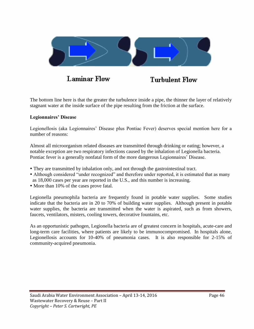
Saudi Arabia Water Environment Association – April 13-14, 2016 Page 46 Wastewater Recovery & Reuse – Part II Copyright – Peter S. Cartwright, PE
The bottom line here is that the greater the turbulence inside a pipe, the thinner the layer of relatively
stagnant water at the inside surface of the pipe resulting from the friction at the surface.
Legionnaires’ Disease
Legionellosis (aka Legionnaires’ Disease plus Pontiac Fever) deserves special mention here for a
number of reasons:
Almost all microorganism related diseases are transmitted through drinking or eating; however, a
notable exception are two respiratory infections caused by the inhalation of Legionella bacteria.
Pontiac fever is a generally nonfatal form of the more dangerous Legionnaires’ Disease.
They are transmitted by inhalation only, and not through the gastrointestinal tract.
Although considered “under recognized” and therefore under reported, it is estimated that as many
as 18,000 cases per year are reported in the U.S., and this number is increasing.
More than 10% of the cases prove fatal.
Legionella pneumophila bacteria are frequently found in potable water supplies. Some studies
indicate that the bacteria are in 20 to 70% of building water supplies. Although present in potable
water supplies, the bacteria are transmitted when the water is aspirated, such as from showers,
faucets, ventilators, misters, cooling towers, decorative fountains, etc.
As an opportunistic pathogen, Legionella bacteria are of greatest concern in hospitals, acute-care and
long-term care facilities, where patients are likely to be immunocompromised. In hospitals alone,
Legionellosis accounts for 10-40% of pneumonia cases. It is also responsible for 2-15% of
community-acquired pneumonia.

Saudi Arabia Water Environment Association – April 13-14, 2016 Page 47 Wastewater Recovery & Reuse – Part II Copyright – Peter S. Cartwright, PE
Controlling Legionella Bacteria
Just as these bacteria are unusual in their method of transmission and behavior inside a water system,
the recommended treatment protocols are also a bit unusual.
Copper-Silver Ionization
The most effective Legionella bacteria inactivation technology to date is copper-silver ionization.
This technology utilizes copper and silver electrodes and direct current to release ions of both metals
into solution. For Legionella inactivation, a concentration in the water supply of 0.2 to 0.8 mg/L of
copper and 0.01 to 0.08 mg/L of silver is required. This disinfection technology has been used in the
U.S. since 1990, with outstanding results. It is being used in hospitals, long-term care facilities and
in office and apartment buildings.
Copper-silver ionization systems are easily installed and maintained. Ingestion of these heavy
metals is limited, because the treatment is typically only on the hot water recirculation loop. The
efficacy of this treatment is not affected by temperature, but the water pH should be maintained
below 8.5. Manufacturers of these systems must obtain EPA registration as a biocide. The
system cost for a typical 250 bed hospital (hot water only) is estimated at $40-50,000.
Chlorine Dioxide
This disinfectant has not been as thoroughly evaluated as copper-silver ionization. The available
field data indicate that a minimum concentration at the hot water taps should be 0.25 mg/L.
Chlorine dioxide must be generated onsite (as a gas), but has greater penetration into biofilms than
chlorine. In addition, it does not produce the THM byproducts associated with chlorine. On the
other hand, chlorine dioxide is relatively corrosive and expensive. Reactions with piping materials
and other compounds in the water will degrade the chemical into chlorite and chlorate byproducts
which are currently under investigation for health effects on their own. Chlorine dioxide systems
also require EPA registration. The costs associated with chlorine dioxide generation, installation and
maintenance are approximately similar to those of copper-silver ionization.
Chloramines
The trend for replacement of municipal chlorination with chloramines (chlorine injection followed
by ammonia), appears to offer an advantage over straight chlorination with regard to controlling
Legionnaires’ disease. Preliminary data from locations where chloramination has replaced
municipal chlorination show a significant decrease in Legionella bacteria Chloramine compounds
appear to effectively penetrate biofilms and are biocidal over a wider pH range than the other
treatment technologies.

Saudi Arabia Water Environment Association – April 13-14, 2016 Page 48 Wastewater Recovery & Reuse – Part II Copyright – Peter S. Cartwright, PE
Hyperchlorination
The injection of high concentrations of chlorine (usually in the form of liquid sodium hypochlorite)
into the water supply is considered the least effective means of inactivating Legionella bacteria. It
has low biofilm penetrating capability, is corrosive to metals and produces hazardous THM
compounds.
POU Filtration
As with the pathogen removal technologies discussed previously, submicron POU filtration is very
effective in the removal of Legionella bacteria from faucet taps and shower heads. Because of the
high cost of these devices, their use is usually limited to high-risk, low flow areas such as intensive
care and transplantation units in hospitals.
UV Irradiation
As described earlier, this technology, utilizing UV irradiation at a wave length peaking at about 254
nm, has a long history of bacteria inactivation in many applications, including residential and
industrial. UV leaves no residue, and suspended solids may shield the bacteria from the radiation.
In addition, the ability of UV to penetrate biofilms has been called into question. On the other hand,
UV irradiation is relatively inexpensive, and if installed with new plumbing (without established
biofilms), it may be very effective, particularly if combined with one of the inactivation technologies
described above.
Standards
A new standard, ANSI/ASHRAE 188-2015, “Legionellosis: Risk Management for Building Water
Systems,” covers risk assessment protocols, and addresses:
• Human-occupied buildings
• Potable water supplies
• Cooling towers
• Evaporative condensers
• Whirlpool spas
• Decorative fountains
• Aerosol generating air coolers
• Humidifiers
• Washers
It emphasizes the development of risk management plans in the form of HACCP (Hazard
Analysis Critical Control Point). It is expected to force institutions to look closely at the
microbiological quality of their water systems.

Saudi Arabia Water Environment Association – April 13-14, 2016 Page 49 Wastewater Recovery & Reuse – Part II Copyright – Peter S. Cartwright, PE
Plumbing Design & Operation
As stated earlier, it is virtually impossible to prevent bacterial proliferation and biofilm growth in
any water system. The preceding mitigation strategies are based on approaches to keep bacteria
growth to a minimum. Additionally, piping materials of construction, plumbing design and system
operation play critical roles in keeping microbial contamination under control.
For example, plumbing design engineers dictate that pipe flow to ensure turbulence be >3 m/sec, and
that all regions of stagnant flow be eliminated.
With regard to pipe materials, in addition to the plastic or metal construction, interior surfaces
should be selected with microorganism attachment and growth in mind Tests on the attachment of
Legionella bacteria on pipe walls showed three times higher concentration on crosslinked
polyethylene and stainless steel than on copper pipe. This is not unexpected as copper is a heavy
metal with antimicrobial properties. On the other hand, metal piping, such as copper, is more
susceptible to corrosion than the plastics – no free lunches.
Following is a list of plumbing design considerations. As all designs contain many site-specific
factors, it should only be used as a set of suggested guidelines.
• Piping material
• Pipe joining procedures
• Pipe size (to ensure turbulent flow at a given flow rate)
• Elimination of deadlegs or other areas of stagnant water
• Adequate backflow prevention (meets code)
• Hot water continuous recirculation
• Risk assessment plan (HACCP) in place
• Frequent water quality monitoring
• System-wide disinfection plans
• Adequate pressure within the system

Saudi Arabia Water Environment Association – April 13-14, 2016 Page 50 Wastewater Recovery & Reuse – Part II Copyright – Peter S. Cartwright, PE
GLOSSARY
Activated Sludge is produced by mixing primary effluent with bacteria-laden sludge in a process that is activated
using aeration and agitation to promote biological treatment.
Advanced Waste Treatment is wastewater treatment beyond the secondary or biological stage of treatment. It
includes the removal of nutrients such as phosphorous and nitrogen and a high percentage of suspended solids. It is
also often called tertiary treatment.
Aerobic refers to life or processes that require the presence of oxygen.
Aeration is the process of exposing something to circulating air.
Anaerobic refers to life or processes that require the absence of oxygen.
Bacteria are single-celled microscopic organisms that grow in nearly every environment on Earth. In wastewater
treatment, they can perform a variety of biological treatment processes, including biological oxidation, sludge
digestion, nitrification, and denitrification.
Biochemical Oxygen Demand (BOD) is the measure of the amount of oxygen consumed in the biological
processes that break down organic matter in water. The greater the BOD, the greater the degree of pollution.
Biosolids are the primary organic solid product of wastewater treatment processes and can be beneficially recycled
or appropriately disposed of via landfilling or incineration.
Denitrification is the reduction of nitrate nitrogen to nitrogen gas.
Effluent is wastewater, treated or untreated, that flows out of a treatment plant, sewer, or industrial outfall.
Influent is water, wastewater, or other liquid flowing into a reservoir, basin, treatment plant, or treatment process.
Infrastructure in the wastewater treatment industry refers to the expansive network of reservoirs, plants, and
pipes above and below ground that provides, processes, and treats the water.
Land Application is the treatment or disposal of wastewater or wastewater solids by spreading them on land
under controlled conditions.
Membrane Bioreactors combine activated sludge treatment and membrane filtration processes to separate
liquids and solids.
Microconstituents are trace complex organic compounds, generally from industrial, medicinal, pharmaceutical,
and personal care products, but may also be naturally occurring. They are sometimes called compounds of
emerging concern (CECs) or endocrine disrupting compounds (EDCs).
Microorganisms are microscopic organisms, either plant or animal, invisible or barely visible to the naked eye;
for example, bacteria, fungi, protozoa, and viruses.

Saudi Arabia Water Environment Association – April 13-14, 2016 Page 51 Wastewater Recovery & Reuse – Part II Copyright – Peter S. Cartwright, PE
GLOSSARY (cont’d)
National Pollution Discharge Elimination System (NPDES) is the permit process established under the
U.S. Clean Water Act that requires municipal and industrial wastewater treatment facilities to obtain permits that
specify the types and amounts of pollutants that may be discharged into water bodies.
Nitrification is the oxidation of ammonia nitrogen to nitrate nitrogen in wastewater by aerobic biological chemical
reactions.
Nutrients are elements or compounds, such as nitrogen, phosphorous, and potassium, that are necessary for plant
growth.
Operations and Maintenance (O&M) is the organized procedure for causing a piece of equipment or a
treatment plant to perform its intended function and for keeping the equipment or plant in such a condition that it is
able to continually and reliably perform its intended function.
Permit is a legal document issued by a government agency. In wastewater treatment, a discharge permit requires
that the plant operator achieve specific water quality standards and discharge limits and also establishes monitoring
and reporting requirements.
Preliminary Treatment is the initial treatment process within a treatment plant where large solids from the
incoming influent are removed to enhance further treatment processes and prevent damage to equipment.
Primary Treatment is the stage in wastewater treatment where screens and sedimentation tanks are used to
remove most material that floats and/or settles. Primary treatment results in the removal of a substantial amount of
suspended matter but little or no dissolved matter.
Receiving Stream is a river, lake, ocean, or other watercourse into which wastewater or treated effluent is
discharged.
Sanitary Sewer is a sewage system that carries only household, commercial and industrial wastewater.
Secondary Treatment is the stage in the wastewater treatment process where bacteria are used to digest organic
matter in the wastewater. Sometimes the term is used interchangeably with biological wastewater treatment.
Sludge is solid matter that settles to the bottom of septic tanks or the material that results from wastewater
treatment plant sedimentation.
Suspended Solids are insoluble materials that float on the surface of or are suspended in wastewater primarily due
to their small size. They can also be called total suspended solids (TSS).
Ultraviolet Disinfection is the process of using ultraviolet light to inactivate disease-causing bacteria and viruses.
Wastewater is used water from a community or industry that contains dissolved or suspended matter.

Saudi Arabia Water Environment Association – April 13-14, 2016 Page 52 Wastewater Recovery & Reuse – Part II Copyright – Peter S. Cartwright, PE
ACRONYMS
BAF Biological Active Filters
Bio-P Biological Phosphorous Removal
COD Chemical Oxygen Demand
CSTR Continuously Stirred Tank Reactor
DO Dissolved Oxygen
F/M Food-to-Microorganism Ratio
FC Final Clarifier
HRT Hydraulic Retention Time
IFAS Integrated Fixed-film Activated Sludge
MBBR Moving Bed Biofilm Reactor
MBR Membrane Bioreactor
MLSS Mixed Liquor Suspended Solids
RAS Return Activated Sludge
RBC Rotating Biological Contactor
SALR Surface Area Loading Rate
SBR Sequencing Batch Reactor
SCOD Soluble COD
SLR Solids Loading Rate (clarifier)
VLR Volumetric Loading Rate
Autotrophic Nitrification
Heterotrophic BOD/Nitrification