Embed Size (px)
Citation preview

Charlotte Mecklenburg Utilities
Wastewater Pumping Station
Standard Specification

TABLE OF CONTENTS Policy.................................................................................................................................1 1.00 General Provisions ................................................................................................2 2.00 Pump Design.........................................................................................................3 2.01 General Requirements ..........................................................................................3 2.02 Number and Capacity............................................................................................3 2.03 Selection Methodology ..........................................................................................4 2.04 Cycle and Pump Run Times..................................................................................6 3.00 Pump Station Design.............................................................................................7 3.01 Location and Access .............................................................................................7 3.01 Structural Design.................................................................................................10 3.03 Piping and Valves................................................................................................12 3.04 Appurtenances ....................................................................................................16 4.00 Force Main Design ..............................................................................................17 4.01 Material................................................................................................................17 4.02 Velocity................................................................................................................19 4.03 Surge Control ......................................................................................................19 4.04 Appurtenances ....................................................................................................19 4.05 Installation ...........................................................................................................20 5.00 Quality Assurance and Quality Control ...............................................................21 5.01 Shop Drawings and Operations and Maintenance (O&M) Manuals....................21 5.02 Service Manual and Spare Parts.........................................................................22 5.03 Pump Station Testing ..........................................................................................22 5.04 Pump Testing ......................................................................................................23 5.05 Force Main Testing..............................................................................................23 5.06 Electrical and Instrumentation/Control System Testing.......................................24 6.00 Submersible Pumping Stations ...........................................................................25 6.01 Materials..............................................................................................................25 6.02 Handling and Installation .....................................................................................28 7.00 Submersible Pumping Station Electrical Specifications ......................................28 7.01 General Provisions ..............................................................................................28 7.02 Basic Electrical Materials and Methods...............................................................30 7.03 Pump Station Electrical Equipment & Installation ...............................................33 7.04 Spare Parts .........................................................................................................41 8.00 Emergency and Standby Power Systems ...........................................................41 8.01 Systems...............................................................................................................41 8.02 Products ..............................................................................................................41 8.03 Execution.............................................................................................................45 8.04 Guarantee and Service .......................................................................................46

Policy It is the policy of Charlotte-Mecklenburg Utilities (CMU) to minimize the need for wastewater pump stations and to limit their construction and use within the system. The basis for this policy is that pump stations cause disproportionate expense in order to provide service to a limited customer base and that failure of pump stations poses significant environmental risks. It is recognized, however, that there are situations where pump stations are a feasible alternative to certain small, permanent treatment facilities as well as a feasible temporary solution for new development. CMU provides the large regional pump stations it deems necessary for orderly system development and operation under the Capital Improvement Plan (CIP). CMU will also consider, on a case-by-case basis, requests to accept new developer funded pump stations in the situations described below.
A The pump station can be eliminated by a project or combination of projects, all of which are included for funding in the approved 5-year CIP. The pump station can be eliminated by a project being done under a reimbursable program and the funds have been made available to CMU for construction.
B The proposed pump station is at an appropriate location and has adequate capacity or expansion capacity to serve as a permanent or long term facility and gravity service is cost prohibitive or not possible due to other circumstances.
C The construction of the proposed pump station would include elimination of one or more existing pump stations.
D The construction of the proposed pump station would facilitate significant progress toward achievement of land use goals and strategies described by current, officially approved planning documents and no other reasonable options are available for service.
In all cases, the receiving system must have available capacity to carry the proposed pump station discharge. Any upgrades required will be the responsibility of the customer requesting the pump station.
1

1.00 General Provisions All wastewater pumping stations must comply with the North Carolina Department of Environment and Natural Resources’ Minimum Design Criteria for the Fast Track Permitting of Pump Stations and Force Mains, as amended to date and available at http://h2o.enr.state.nc.us/ndpu/documents/md4.doc. Pumping Stations with peak, firm capacities of less than 2 million gallons per day (MGD) or pumps of 150 horsepower(HP) or less shall be supplied with submersible type pumps depending on head conditions and the availability of suitable pumps. The type of pump used near this limit will be approved by CMU on a case-by-case basis. The requirements for submersible type stations are found in Sections 6 & 7. Stations with a peak, firm capacity of 2 MGD or pumps larger than 150 horsepower (HP) shall be individually engineered and housed in a building appropriate for the specific application. Pumping Stations accepting flow from low pressure sewer systems shall employ odor control measures. Each pumping station shall include an emergency power generator capable of operating the station and all its systems at full capacity with both pumps operating. Each pump station plan set shall contain a sheet with the total service area (drainage basin) outlined, land use assumptions, and detailed flow calculations used to determine the required station capacity. Additional engineering calculations that have been signed, sealed, and dated by a Professional Engineer (PE) licensed in North Carolina shall include, at a minimum, the following:
A Total dynamic head calculations for all applicable pumping situations. B System curve/pump curve analysis used to determine pump selection and
operational point. C Detailed surge analysis under all operating conditions. D Pump station cycle and pump run times, including an evaluation of any
depressed sections of the force main to determine if the pump station is capable of completely flushing the force main section being evaluated in a single pumping cycle.
E Pump station flotation/buoyancy. F Available emergency storage capacities at average and peak wastewater
flows for pump stations. G Minimum velocity within the force main. H Maximum detention times within the pump station and force main. I Downstream sewer evaluation demonstrating that the pump station discharge
will not overload the receiving sewer line:
1 In situations where the pump station discharges into a gravity sewer, the downstream gravity sewer shall be evaluated based on peak flow from the proposed project as well as peak flows already tributary or permitted to the downstream gravity sewer.
2 In situations where the pump station discharges into another pump station, the downstream pump station shall be evaluated to verify its ability to convey peak flows from the proposed project as well as peak flows already tributary or permitted to the downstream pump station.
3 In situations where the pump station discharges into a force main, the common force main shall be evaluated on peak flows from the proposed project as well as peak flows already tributary to the common force main. The ability of each pump station tributary to the
2

common force main to pump against additional head created by greater flows through the force main shall also be evaluated. An evaluation of the discharge point of the downstream force main shall also be performed.
2.00 Pump Design 2.01 General Requirements
A Only non-clog pumps designed and manufactured for use in conveying raw, unscreened wastewater shall be acceptable. Pumps shall be adequately protected from damage due to failure conditions specific to the selected pump type and pump station configuration.
B Pump selection and construction shall consider the duty requirements as well as the physical and chemical characteristics of the wastewater.
C Pumps shall be suitable for continuous duty in conveying raw, unscreened wastewater.
1 Pumps shall be capable of handling a three-inch solid and any trash
or stringy material that can pass through a four-inch hose. Impellers shall have blades that are generally forward rounded or otherwise configured to avoid catching solids, trash, and stringy material.
2 Pump suction and discharge openings shall be no less than four inches in diameter.
2.02 Number and Capacity
A Pump Stations shall be provided with pumps as outlined below.
1 Multiple pumps shall be used such that the pump station is capable of conveying the peak hourly wastewater flow to its desired outfall location with the largest single pump out of service.
a In duplex pump stations, the pumps shall be of the same
capacity. b If pumps in series are required to meet capacity or total
dynamic head requirement, each set of pumps in series shall be viewed as a single pumping unit.
c Priming pumps as well as any other auxiliary system that is required for pump functionality shall also be provided in multiple numbers.
2 Determination of pump capacity shall be based on wastewater flows
expected to become tributary to the pump station for the entire drainage area at build out. For regional pump stations, pump capacity shall be based on wastewater flows expected to become tributary from the entire service area over the life of the pump station.
3 The minimum allowable design daily wastewater flow to the pump station shall be determined as follows:
3

a Where a pump station is designed to serve a developed
service area, historical potable water use or wastewater flow generation data may be used to determine design daily wastewater flows.
b Where a pump station is designed to serve a broad service area for which specific development is not known, design daily wastewater flows may be established based on historical data for the broad service area or CMU planning criteria.
The selected peak hourly wastewater flow to the pump station shall be appropriate for the service area as well as the associated wastewater generation patterns and population being served by the pump station. In small community type stations, this should also include the discharge capacity of any public or community pool. The minimum peak hourly wastewater flow to the pump station can be calculated using the design daily wastewater flow along with a peaking factor determined from the following equation with a minimum factor of 2.5.
PF = peaking factor Qphf = peak hourly flow (gallons per day) Qddf =design daily flow (gallons per day) P = service population (thousands) P
PQQ
PFddf
phf
++
==4
18
B Pump capacity shall also be based upon the need to maintain a minimum
velocity of two feet per second. 2.03 Selection Methodology
A Pump selection shall be based on a hydraulic analysis of the system through which the wastewater is to be conveyed.
1 The design operating point(s) of the pump(s) shall be determined
using a pump curve-system curve analysis. Pumps shall be selected such that the pumps shall be capable of pumping the required capacity for all total dynamic head requirements developed by the system for the lifetime of the pump station. All pumps shall be designed in accordance with applicable portions of ANSI / Hydraulics Institute 1.1- 1.6, 2.1-2.6 and 9.1-9.6.
a A system curve, plotting total dynamic head versus capacity,
shall be developed for all operating conditions that may be imposed on the system. Total dynamic head requirements for the system shall be calculated as the total of the following individual components:
4

(1) Static head requirements of the system, including that associated with both the suction and discharge sides of the pumps, shall be evaluated. In addition to calculating static head with the discharge elevation of the force main, any intermediate high points in the force main that would have an effect on the total dynamic head requirements of the pump shall be analyzed.
(2) Friction head requirements of the system, including that associated with both the suction and discharge sides of the pumps, shall be evaluated. The friction head shall be calculated using the Hazen-Williams formula:
hf = friction head for pipe segment evaluated (feet) L = length of pipe segment evaluated (feet) Q = pumping rate (gallons per minute) C = Hazen-Williams coefficient D = diameter of pipe segment evaluated (inches)
⎟⎟⎠
⎞⎜⎜⎝
⎛= 87.485.1
85.144.10DCQLhf
All operating conditions shall be evaluated including, but not limited to: multiple pump operation within the subject force main, simultaneous pump station operation for common force main situations, as well as the possibility for gravity flow conditions in force main segments with extreme negative slopes that may not flow full.
(3) Head derived from any minor losses of the system, including that associated with the both the suction side and discharge side of the pump, shall be evaluated. Such minor losses shall include head derived from valves and other fittings such as tees, bends, angles, etc.
(4) If applicable, the pressure head at the junction of the existing force main shall also be evaluated for its effect on the total dynamic head requirements of the system. The evaluation shall take into account the effects of simultaneous pump station operation as well as multiple pump operation in other pump stations.
b System curves shall be generated and evaluated not only for
present day conditions, but also for those conditions that may exist over the expected lifetime of the pump station.
(1) The Hazen-Williams friction coefficient, C, appropriate
for the force main pipe material and age of the force main shall be used.
(2) The following maximum values shall be allowable for C:
5

Pipe Type Initial Service C End-of-Service C DI 125 100 PVC 140 120 HDPE 140 120
(3) Friction head and minor losses associated with the system shall be evaluated at both the initial service condition and the end-of-service condition.
c The design operating point(s) shall be defined as the
intersection of the pump curve and the calculated system curve(s).
2 Pumps shall be selected such that all design operating points are on
the pump curve as supplied by the pump manufacturer. In addition, pumps shall be selected such that the net positive suction head available (NPSHA) shall be greater than the net positive suction head required (NPSHR) for the pump at each of the design operating points.
3 Pumps shall be selected such that the pumps will not cavitate at any of the design operating points. Pumps that operate within the unstable portion of the pump curve under any of the expected design conditions shall not be allowed. Freewheeling (i.e., operating at pump run-out) or deadheading (i.e., operating at pump shut-off) of pumps shall not be allowed. All continuous duty operating conditions shall be within the manufacturer’s Allowable Operating Region and the design operating points shall be within the manufacturers Preferred Operating Region as defined in ANSI/Hydraulic Institute 9.6.3. Pump selections proposing maximum diameter impellers for the given pump model and casing size will not be accepted.
4 Pumps shall be selected such that their operating efficiency is maximized during all hydraulic conditions that may exist over the expected lifetime of the pump station.
B Consideration shall be given to minimizing motor speeds during the pump
selection process. C The motor horsepower shall be at least 1.15 times what is required to ensure
that the pump is non-overloading throughout the entire pump performance curve from shut-off through run-out.
2.04 Cycle and Pump Run Times
A Constant speed pumps shall be cycled such that the number of starts are
minimized and resting times are maximized to avoid overheating and overstressing of the pump motor.
1 Automatic pump alternation shall be provided. 2 Pumps shall be designed to operate between two and eight times per
hour at design daily flow with a strong preference for 4 to 5 cycles per hour.
6

a The following equation shall be used to determine the active storage volume in the pump station (i.e., the volume between the pump-on and all pump-off elevations) required to elicit the required pump cycle time:
V = active volume within the pump station (gallons) T = allowable cycle time between starts (minutes) Qddf = design daily flow to pump station (gallons per minute) Q = pumping rate of a single pump (gallons per minute) ⎟⎟
⎠
⎞⎜⎜⎝
⎛−=
TQV ddfddf 1
b If the wastewater generation patterns are such that less than two pumping cycles per hour will occur at design daily flow or if the pump station is intended to provide equalization of hydraulic surges, measures to control odor and corrosion shall be employed when resultant detention times cause septic conditions. These measures shall take into consideration protection of the pump station, the force main, the outfall sewer, any related appurtenances, as well as the surrounding area.
B Consideration shall be given to using variable speed pumps for main pump
stations or those pump stations that discharge directly into a wastewater treatment facility.
C Pump run times shall be such that excessive wear of the pumps does not occur.
1 At design daily flow, adequate time shall be provided to allow a
constant speed pump to “ramp up” to full speed before the pumping cycle ends.
2 Pump run times at design daily flow shall not be less than or greater than those recommended by the pump manufacturer.
D Submersible pump/motor assemblies, including lifting brackets, are to remain
completely submerged at all times. 3.00 Pump Station Design 3.01 Location and Access
A The pump station shall be located on a tract of land with an assigned address or easement properly deeded and recorded to the City of Charlotte. The deeded tract shall include the immediate pump station site and any access drive. The tract shall be large enough to locate the pump station structures, an area suitable to locate an emergency generator, and have enough space to park and maneuver maintenance vehicles. The tract or easement should include any cut or fill areas adjacent to the access drive and fenced station site and a 20’ wide by 25’ deep turnaround area.
7

1 Pump stations shall be located and designed to minimize the
development of nuisance conditions (i.e., noise, odor, etc.) in the surrounding area. A grading and landscape plan shall be included in all pump station plans.
a Pump station sites shall be accessible by an all-weather
driveway, dedicated solely to station access, provided from a hard surface road.
b The driveway shall be at least two feet above the 100-year flood elevation as identified on the most recent FEMA Flood Insurance Rate map when available or as established through appropriate modeling techniques.
c The roadway shall be designed to accommodate the largest vehicle expected to service the pump station. In no case shall the driveway be less than 14 feet in width or a curve radius of less than 90 feet.
d At a minimum, the driveway shall be constructed from a six-inch layer of compacted aggregate base course (ABC) stone over a suitable compacted subgrade. Stone and subgrade shall be compacted to 100% of max. dry density as determined by the standard proctor test (ASTM D-698). In no case shall uncompacted gravel or stone material be allowed for driveway construction. Drives with a slope of less than 5% may be gravel. Drives with a slope over 5% must be paved with six inches of compacted stone and 1 ¾-inches of I-2 bituminous concrete or superpave equivalent. The maximum allowable slope is 10%. Driveways in existing or planned developments shall be surfaced to match adjacent drives from road to station.
e Stations in close proximity to sensitive or significant streams or bodies of water will be required to have a spill containment basin. This basin will have a minimum storage volume of 24 hours of the average hourly flow. A larger basin may be required and the exact volume required will be determined on a case-by-case basis.
B Security
All ports of entry into pump station structures, vaults, panels, etc. shall be lockable. The pump station shall be provided with adequate outdoor and indoor lighting to facilitate normal and emergency operation and maintenance activities during daylight and non-daylight hours. Safety placards for all pump station structures and equipment, as required by Federal, State, County, and City agencies shall be provided and be readily visible. Fencing: Fence shall be 7'-0" high overall around the entire perimeter of the station site. Double-swing gates shall have a minimum clear opening of 14 feet. Fencing shall be colored and supplied with matching privacy slats of brown,
8

black, or green. Local ordinances may require additional visually enhanced materials.
1 Installation: Fencing shall be installed true to the line and grade
indicated or directed. Fabric shall be pulled tight and shall maintain an even clearance above grade. Unless otherwise specified, fencing shall be installed in strict accordance with the manufacturer's instructions. At ditches and low points, rods, bars, or extra fabric shall be used to close the area. All fittings necessary to make a complete installation are to be malleable iron, pressed steel, or aluminum. All ferrous material shall be hot dip galvanized to insure uniform heavy zinc coating. Concrete shall be 3000 pounds per square inch (psi) minimum strength.
2 Fabric: The fabric shall be composed of 9 gauge steel wire helically wound to form a continuous chain link fabric having a 2-inch mesh. Top and bottom edges shall have a twisted and barbed finish. The fabric shall be manufactured in accordance with ASTM A-392 Class 1 and in accordance with the Chain Link Fence Manufacturers Institute.
a Fabric shall be hot-dip galvanized after weaving to produce a
zinc coating not less in weight than 1.2 ounce per square foot of uncoated wire surface.
b Wire in the fabric shall meet minimum breaking strength of 1,290 pounds after galvanizing.
3 Line Posts shall be 2.375 inch O.D. galvanized pipe, schedule (Sch.)
40, 3.65 lbs./ft. Posts to be spaced no more than 10 feet on center and set 28-inches deep in full 3 foot deep, 8-inch diameter bell-shaped concrete footings, crowned to shed water.
4 Top Rail shall be 1 5/8" O.D. Sch. 40 pipe hot galvanized and shall be furnished in random lengths averaging not less than 20 feet, jointed with extra long pressed steel sleeves, hot galvanized, making a rigid connection but allowing for expansion and contraction. Top rail to pass through base of line post tops or barbed wire arms and form a continuous brace from end of each stretch of fence. Rail to be securely fastened to terminal posts by beveled edge bands and rail end fittings.
5 Fabric Ties for attaching fabric to line posts, top rail or top wire, shall be aluminum strip or 9 gauge wire. Used on top rail every 24-inches; on line posts every 14-inches.
6 Barbed Wire: The fabric shall be surmounted with 3 strands of barbed wire. Each strand shall consist of 2 (two) No. 12-1/2 twisted copper-bearing steel line wires hot galvanized, with No. 14 gauge aluminum 4 point barbs spaced not more than 5-inches apart. The barbed wire shall be manufactured in accordance with ASTM A-121. All intermediate, gate, and corner posts shall be equipped with extension arms for supporting barbed wire with gate and end post arms vertical. Line post arms shall be galvanized pressed steel with self-locking slot and provision for passing top rail. The corner arm base shall be malleable iron and the extension pressed steel with set screw.
9

7 End and corner posts shall be 2.875-inch O.D. galvanized pipe weighing 5.79 lbs./LF. Gate posts to be 4-inch O.D. copper bearing galvanized pipe weighing 9.11lbs./ft. All to be set in full 3 feet deep 10-inch diameter bell-shaped concrete footings crowned to shed water.
8 End and Gate Posts Tops shall be galvanized malleable iron, drive fitting outside of post to exclude moisture.
9 Brace and Tension Bands shall be unclimbable beveled edge type with 5/16-inch diameter square shouldered galvanized steel carriage bolts, non-removable from outside fence. Tension bands shall be spaced no more then 14-inches apart.
10 Bracing: All corner, gate, and terminal posts shall be braced by means of 1-5/8-inch O.D. horizontal compression member, securely attached to terminal and first line posts with malleable iron fittings, beveled edge bands, and truss braced from first line post to bottom of terminal by 3/8-inch rod and turnbuckle. Corner posts to be so braced in each direction.
11 Tension Bars for attaching fabric to terminal posts shall be 3/16" x 3/4" high carbon steel attached to terminal posts by means of beveled edge bands.
12 Bottom Tension Wire shall be 7 gauge marcelled galvanized high carbon coiled steel wire.
13 Gates: Gates shall be double-swing and frames shall be 2-inch O.D. with 1 5/8 –inch internal bracing welded at all joints to provide rigid watertight construction. Filler fabric shall be same as used in line of fence with barbed wire at top. Hinges shall be pivot type malleable iron or pressed steel. Latch shall be drop bar type securely fastened to gate frame and to engage a 2-inch I.D. pipe sleeve driven 18-inches minimum into earth.
3.02 Structural Design
A Materials of Construction
1 Pump station structures shall be designed and built in complete compliance with all applicable state, local, and federal codes as well as any applicable Occupational Safety and Health Administration (OSHA) and National Fire Protection Association (NFPA) standards.
2 Material selection for pump station structures shall be based on installation and operating factors including, but not limited to, the following:
a Physical, chemical, and biological wastewater characteristics. b Corrosive gas production. c Soil characteristics. d Groundwater presence.
3 Pump station structures shall be completely separated unless made
completely watertight and gas-tight.
10

4 Pump station structures shall be adequately protected to minimize damage from vehicular traffic.
5 Wet wells and valve vaults shall be concrete and sized with adequate clearances for equipment maintenance.
6 Shop drawings for wet well, valve vault, and pump dimensions shall be submitted to the owner for approval.
7 Wet wells shall have a minimum diameter of six feet and precast wet wells a maximum of 12 feet.
B Buoyancy Protection
1 Below-ground pump station structures shall be protected from the
buoyant forces of groundwater. 2 Buoyancy protection shall be demonstrated through the use of
flotation calculations.
a Flotation calculations shall be performed on below-ground pump station structures using the assumption that the elevation of the groundwater table is equivalent to the ground elevation.
b Flotation calculations shall not add the weight of the pumps, internal piping and appurtenances, or wastewater present in the pump station, including the wastewater below the all pumps-off activation level, into the downward forces used to counteract buoyancy.
c The saturated weight of any soil above the extended footing of the pump station structure shall be allowed in the flotation calculations.
3 Flotation calculations shall show that the design of the below-ground
pump station structures will be protected from buoyancy with a factor of safety that is greater than 1.5.
C Flood Resistance
1 Pump station structures as well as all associated equipment and
appurtenances shall be protected so that the pump station remains fully functional, operational, and free from physical damage during a 100-year flood.
2 The pump station shall be protected from inundation of floodwaters by elevating finish grade at least two-feet above the 100-year flood elevation.
3 The 100-year flood elevation shall be that as identified on the most recent FEMA Flood Insurance Rate map as amended by local agencies when available, or as established through appropriate modeling techniques.
D Solids Collection
1 Wet wells shall be designed to minimize pump or pump suction piping operational problems resulting from the accumulation of solids and grit material within the wet well.
11

a Acceptable designs include the use of fillets and sloped wet
well floors. Preference is for a self-cleaning design employing a steeply sloped influent line entering near the bottom of wet well.
b The design of fillets and slopes shall be such that solids are effectively moved toward the pump or pump suction piping.
2 No projections within the wet well or on the well wall which would
allow deposition of solids under normal operating conditions shall be allowed.
E Depth
1 Pump Submergence Depth
a Sufficient submergence of the pump or pump suction piping shall be provided to prevent the occurrence of vortexing within the wet well.
b In no case shall the all pumps-off activation level be less than the minimum level required for successful pump operation, as recommended by the pump manufacturer.
c Submersible pumps, including lifting brackets, shall be fully submerged at all times.
3.03 Piping and Valves
A Influent Line A single influent line shall be oriented so that turbulence and air bubbles do not affect pump operation. Incoming flow shall not fall onto any pump. Influent piping shall be ductile iron within the station fence enclosure or a minimum of 36 feet.
B Suction and Discharge Piping Configurations
1 Each pump shall be provided with separate suction (when applicable)
and discharge piping systems. Pump suction and discharge piping shall be PC 350 Ductile Iron no less than four inches in diameter with the final size being selected to achieve velocities between four and ten feet per second(fps) with a preference for six to eight fps. The pipe and fittings shall have a minimum of twelve inches (12") clearance from any wall or floor and there shall be a minimum 30-inch clearance between the piping of each pump.
2 Flange joints and accessories: All fittings inside pump station and through the emergency pump connection shall be flange joint ductile iron fittings. Flange joints shall be either Class 125 or Class 250, as required. Flanges, flange bolts and nuts, and gaskets shall conform to the dimensional requirements of ANSI B16.1 for Class 125 or ANSI B16.2 for Class 250. Bolts shall be ASTM F593 316 stainless steel (SS) and have standard hexagonal heads and ASTM F 594 304 SS
12

nuts. An anti-seize compound shall be used during assembly. No all-thread connections are allowed between valves or between valves and piping.
3 The suction and discharge piping systems shall be provided with sufficient valves to effect proper operation and maintenance of the pump station during both normal and emergency conditions. Pump isolation valves shall have the seat oriented towards the pump. All valves within the station enclosure shall be open left.
a Valves shall be suitable for use with raw, unscreened
wastewater and shall be of a design suitable for its function, its installation location, as well as the normal and maximum operating pressures expected at the pump station. Valves and piping shall have sufficient room for a nut/bolt fastener.
b A full-closing eccentric plug shut-off valve shall be provided on the discharge piping of each pump and on the suction piping of each dry well pump.
c A swing check valve shall be provided on the discharge piping of each pump, between the pump and the shut-off valve. Check valves shall be placed in the horizontal position. All valves shall be located so that they are readily accessible for maintenance.
4 An emergency pump-out connection shall be provided outside the
pump station per standard detail 2. The force main shall be fitted with an eccentric plug valve and downstream of this valve shall be a flanged tee with a riser pipe extending vertically to the surface. The riser pipe shall have an eccentric plug valve fitted on the end. This plug valve shall have a blind flange with a male cam-lok connector with a ¼” National Pipe Taper (NPT) ball valve and dust cap. The buried plug valve shall operate with a two-inch square nut and the surface plug valve shall operate with a wrench. The Contractor shall furnish a valve key and a wrench as part of the permanent station equipment. The surface plug valve shall be set in a drain bed of #67 crushed stone at least six inches deep and shall be housed in a pre-cast concrete vault or .5 Cubic Yard minimum.
C All valves shall be as specified below.
1 Ball valves shall be 304 stainless steel construction with iron pipe
thread, screw ends, as required and having a working pressure of 200 PSI.
2 Swing Check Valves: Check valves 3-inches and larger shall be horizontal swing check valves for sewage service furnished with iron bodies, bronze mounted, single disc, swing type full opening, with lever and weight assist (compatible with the specified pumps and working pressure) and with flange ends conforming to ANSI Specification B16.1. Valves 8-inches and larger shall be cushioned. Valves shall be manufactured by Kennedy, CCNE, or M&H. All working parts shall be removable through the top of the valve unless otherwise required by the installation. When check valves are located
13

in vaults or other areas with limited access, Mega-flange or equivalent fittings with stainless steel bolts will be located immediately upstream of each check valve to facilitate maintenance.
Materials used in the construction of swing check valves required herein shall be in accordance with the following specifications:
a Shaft Seals: Shaft seals shall be designed for the use of
Standard O Ring Seals, or for a conventional stuffing box. b Inspection: The manufacturer shall furnish to the Engineer
written certification that all valves and material furnished under this specification have been tested and found to conform with the requirements of AWWA Standards for valves C-508 and ASTM and ANSI requirements for materials as applicable.
c Coating: Check valves shall be factory epoxy coated. d Valve Body Types: Valve bodies shall be manufactured with
flanged ends conforming in dimensions and drilling to ANSI B16.1 Class 125 Cast Iron Flanges. The short style valve body will be furnished as required to complete the installation as shown on the Plans.
e Valve Drawings: Plans for valves and assemblies will be approved by the Engineer prior to construction.
3 Plug Valves: All valves for pressure sewers and force mains shall be
eccentric plug valves as follows:
a Plug valves shall be non-lubricated, with a plug facing of a material specifically recommended by the valve manufacturer for the indicated service and shall have stainless steel permanently lubricated upper and lower plug stem bearings. Valve seats shall be nickel. Valves shall be designed with adjustable seals that are replaceable without removing the bonnet. The bearing and seal area shall be protected with grit seals. Valves shall be factory epoxy coated. Area of port opening for all valves shall be no less than 81% of full pipe area. Valves shall have a direct pressure rating of 100 psi with a working pressure of 175 psi for 12-inch and smaller valves and 150 psi for 14-inch and larger valves. Bi-directional shutoff is required. Plug valves shall be as manufactured by Dezurik only, due to standardization of spare parts. Valves with flange ends shall be provided where indicated. Flanges shall be in accordance with ANSI B16.1 except that the four holes straddling the principal axis of the valve may be tapped and connected to the adjacent piping with cap screws of adequate size as recommended by the valve manufacturer and approved by the Engineer.
b Plug valve operation shall be as indicated on the Plans and as
follows:
14

(1) Buried valves, and all valves under 8-inches in size, shall have 2-inch square operating nuts.
(2) Valves 8-inches and larger require gearing in enclosed gear cases. Gearing shall be in accordance with the valve manufacturer's recommendations as required to permit easy operation of the valve by one man without excessively large hand wheel or cranks. Hand wheels shall not exceed 16 inches in diameter.
c Extension stems, stem guides, operating levers, and other
miscellaneous items required for a complete installation shall be provided in accordance with the requirements and recommendations of the valve manufacturer. Operating nut shall be within 12” of grade.
d Discharge valves in vault shall be installed with adjustable aluminum pipe cradle and stainless steel standpipe. Buried valves shall be provided with a valve box conforming to CMU water standard detail 2. The valve box shall not transmit shock or stress to the valve and shall be centered and plumb over the operating nut, with the box cover flush with the surface of the pavement or other existing surface. Where the box is not set in pavement, the top section shall be anchored by a concrete pad, or an approved precast concrete pad, set flush with the existing terrain. The top section will be encased into the concrete pad.
D Pipe Connections
1 Flexible pipe joints shall be used between the pump station structures
to allow for differential settlement without compromising the integrity of the overall pump station.
2 Pipe inlets and outlets of pump station structures shall be made watertight with flexible boots according to ASTM C-923 and grouted.
3 Existing pump station structures shall be core drilled or saw-cut when connections are made through the structure wall. In no case shall penetrations into pump station structures be made by hammering.
E Water Service
In areas where potable water is available, the station shall be furnished with a ¾” water service and freeze-proof yard hydrant. A reduced pressure principle backflow prevention device is required per CMU specifications. This shall be located within the fenced station enclosure and supplied with a strainer screen, heating element, and an insulated cover anchored with stainless steel hardware. If municipal water is not available, a well and yard hydrant shall be provided. The well shall have a minimum capacity of 10 gal./min. at 40 psi and be clearly labeled as non-potable. Yard hydrants shall be mounted 30-inches high, frost-proof and equipped with stems and seat washers that are removable through the top of the hydrant. Operating rod shall be brass. The yard hydrant shall be installed complete with washed stone drain bed of at least 1 cubic foot and an 18-inch square concrete splash pad.
15

3.04 Appurtenances
A Pump Removal Methods/Equipment 1 Provisions shall be made so that the largest piece of equipment
installed at the pump station may be removed such as supplying a hoist or designing sufficient clearance for mobile hoisting equipment.
2 Pump station structures shall be provided with access of sufficient size such that the largest piece of equipment may be removed without damaging the integrity of the structural design.
3 Pump stations shall be provided with a system that allows for the removal and installation of the pumps without requiring entry into the wet well and with clear vertical access.
a Each pump shall be provided with a 304 stainless steel guide
rail and lift-out chain section with guide cable. b Both the guide rail and the lift-out chain shall be capable of
withstanding the forces required to disengage the pump from the wet well.
c Both the guide rail and the lift-out chain shall be manufactured of stainless steel.
B Access Equipment
Structure shall be designed so that access to perform both routine and emergency operations is convenient, unobstructed, and safe. Each structure shall have a separate means of access. Steps, ladders, stairs, landings, hatches, and other means of access shall conform to OSHA standards as well as all applicable local and state building codes regarding design characteristics.
C Ventilation Equipment 1 Pump stations shall be adequately vented in accordance with local
and state building codes as well as OSHA and NFPA standards. The Class 1 explosion hazard zones, as defined in the NFPA 820 code, shall be identified on the plans. Pump station temperature and humidity shall be controlled to a level appropriate for reliable operation of the electrical and instrumentation/control equipment.
a At a minimum, pump station wet wells shall be provided with a
3” ductile iron gooseneck-type vent with a stainless steel insect / bird screen.
b Vent elevations shall be a minimum of four feet above the 100-year flood elevation as identified on the most recent FEMA map when available or as established through appropriate modeling techniques.
D Other Equipment
Pump station structures other than the wet well shall be provided with a means to remove accumulated water and wastewater from the structure. All floor and walkway surfaces shall be sloped such that water and wastewater
16

drains to the removal area by gravity. Acceptable removal means include the following:
1 A sump for installing a portable pump. 2 A non-arcing sump pump system that is capable of automatic and
manual operation with three automatic operating levels: all pumps-off, pump-on, and high water alarm. It shall have a minimum ½ HP motor and a capacity of 1000 gallons per hour at a TDH of 30’. The discharge piping of the sump pump shall be provided with an appropriate check valve and shut-off valve to prevent back flow of wastewater from the wet well into the structure and to facilitate removal of the sump pump.
4.00 Force Main Design
4.01 Material
A Pipe material and specifications shall be selected based on the installation and operating conditions of the force main following installation. Such factors shall include, but shall not be limited to:
1 Installation depth and overburden pressure. 2 Soil conditions and groundwater presence. 3 Corrosion resistance from both external and internal sources. 4 Strength required to withstand internal pressures expected during
normal operation as well as those resulting from hydraulic surges and water hammer.
B Force mains shall be constructed of one of the following types of pipe:
1 Ductile iron pipe (DIP), Pressure Class 350
a Pipe shall conform to ANSI/AWWA C151/A21.51 “Ductile Iron Pipe, Centrifugally Cast in Metal Molds for Water or Other Liquids” and shall be cement mortar lined in accordance with ANSI/AWWA C104/A21.4.
b All fittings shall be ductile iron and shall conform to ANSI/AWWA C110/A21.10 “Ductile Iron and Gray-Iron Fittings, 3 In. through 48 In. for Water and Other Liquids” or ANSI/AWWA C153/A21.53 “Ductile Iron Compact Fittings, 3 In. through 66 In., for Water Service.” All fittings shall be epoxy lined and coated according to AWWA C116/A21.16-98.
c Force mains of DI pipe shall have mechanical or gasketed push-on type joints. Restrained joint DI pipe will be used for thrust restraint. Retrofit restraining devices will not be allowed.
d Gaskets shall be manufactured of vulcanized natural or synthetic rubber in accordance with ANSI/AWWA C111/A21.11 “Rubber Gasket Joints for Ductile Iron and Gray-Iron Pressure Pipe and Fittings.”
17

e Flanged DI pipe shall conform to ANSI/AWWA C115/A21.15 “Flanged Ductile Iron Pipe with Ductile Iron or Gray Iron Threaded Flanges”.
f Consideration shall be given to the existence of or the potential for development of corrosive environments within and outside the force main. Sources of corrosion may include: acidic soils, septic wastewater, and air entrainment within the force main. Where corrosion is deemed to be a serious problem, DI pipe shall be provided with an alternate coating appropriate for the pipe material and situation. Such coatings shall be manufactured or applied in accordance with the appropriate ANSI and AWWA standards.
2 Polyvinyl chloride (PVC)
a PVC material used in the manufacture of PVC pipe shall conform to ASTM D1784 “Rigid Poly(Vinyl Chloride) (PVC) Compounds and Chlorinated Poly(Vinyl Chloride) (CPVC) Compounds.”
b PVC pipe shall conform to AWWA C900 or C905. The thickness and pressure class of PVC pipe required for the installation and operating conditions during the expected service life of the force main shall be determined in accordance with AWWA C900 or AWWA C905 but shall be a minimum of Pressure Class 200 with an SDR of 14 or less.
c Force mains of PVC pipe shall have elastomeric gasketed push-on type joints. Gaskets shall be manufactured in accordance with ASTM F477 “Standard Specification for Elastomeric Seals (Gaskets) for Joining Plastic Pipe.”
d Mechanical joint DI epoxy coated pipe fittings conforming to ANSI/AWWA C110/A21.10 and C116/A21.16-98 shall be used for force mains four inches in diameter and larger.
e PVC pipe shall be shipped, stored, and strung in a manner to limit its total accumulated exposure to sunlight and UV radiation to no more than four weeks.
3 All pipe used for force main construction shall be labeled or otherwise
identified as conveying wastewater.
a All force mains shall be clearly identified with green plastic locator tape made specifically for that purpose. The tape shall be marked with black lettering clearly identifying the pipeline as sanitary sewer. The tape shall be Type III Detectable Marking Tape as manufactured by Lineguard, Inc., or approved equal. The tape will be placed both approximately 1 foot above the pipe and also 2-feet below the ground surface.
b A 16-gauge solid copper coated tracer wire shall be laid on top of PVC force mains. This wire shall be secured to the pipe near every bell and at the center of each pipe joint. This wire shall be brought into air release valve vaults and secured to the stainless steel hook along with the valve shutoff cable.
18

c Aboveground markers shall be used every 300’ on straight runs, 100’ on curves, and at every significant change in direction or when otherwise limited by sight distance. Above-ground markers shall be 72”h x 3 ¾” w, and white in color as manufactured by Rhino Fiber3rail (product FR72-W) or approved equal. Markers shall be installed as recommended by the manufacturer.
4.02 Velocity
A Wastewater velocity occurring in a force main shall be calculated using the
continuity equation, Q=VA. A self-cleansing velocity of at least two feet per second shall be provided throughout the length of the force main. The ability to provide velocities of between three and eight feet per second is desirable to resuspend any solids that may have settled out.
B Anchorage
1 Force mains shall be adequately anchored to resist thrusts that may
develop at bends, tees, plugs, end-of-line valves, and at any other location where a change in flow direction occurs. Such anchoring shall be provided through the use of original manufacture restrained joint pipe. Retrofit restraining devices are not allowed.
2 Anchoring devices shall be designed to withstand force main pressures of at least 25 percent greater than the maximum pump shut-off head plus an allowance for water hammer and an appropriate factor of safety or to test pressure.
4.03 Surge Control
A Force mains and their associated pump stations shall be analyzed with
respect to the development of hydraulic transients and force main design shall be such that active devices for control of transient hydraulic conditions are minimized. When necessary, the following shall be acceptable control strategies when approved by CMU:
B Variable-speed pumps or constant-speed pumps in combination with soft start / stop motor starters.
C Pumps with augmented rotational inertia. D Construction of the force main using a higher-strength pipe. E Vacuum relief valves. F Specialized control and/or release valves and other devices designed to
prevent transient pressures from reaching levels that could damage the pump station and force main systems.
4.04 Appurtenances
A Air Release and Air / Vacuum Relief Valves
1 The route of the force main shall be such that the number of air release and vacuum relief valves is minimized.
19

2 An automatic air release valve shall be provided at all high points to prevent air locking of the force main. An automatic combination air release and vacuum relief valve will be located at the ultimate high point and when necessary for surge control where sub-atmospheric pressures or column separation may occur. Automatic air release valves shall be used at other local high points. Air release valves are required when the difference between the low point and high point exceeds one pipe diameter. These valves shall be of the quick-opening, slow-closing type and may be standard height or short body design with a minimum 2-inch diameter screw-threaded inlet. Valve body shall have a removable bonnet secured with 316 stainless steel fasteners to facilitate maintenance of the internal working parts. Outlet is to be screw-threaded. Air and vacuum sewer valves shall be mounted to force main through the use of a bronze corporation stop and stainless steel tapping saddle followed by a stainless steel ball valve. Shop drawings shall be submitted to the Engineer for approval prior to ordering materials. Air release valves shall be as manufactured by APCO, Crispin, Vent-o-mat or approved equal. Combination air and vacuum relief valves shall be as manufactured by Vent-o-mat only, due to their unique design.
4.05 Installation
A Joints and Bedding 1 Force mains shall be installed such that pipe and joint deflection is
minimized. CMU installation methods will be followed and will require no less than the following:
a Force mains of DI pipe shall be installed in accordance with
AWWA C600 “Installation of Ductile Iron Water Mains and Their Appurtenances.”
b Force mains of PVC pipe shall be installed in accordance with AWWA C605 “Installation of Underground Installation of Polyvinyl Chloride (PVC) Pipe and Fittings for Water.”
2 Continuous and uniform bedding and backfill that is appropriate for
the soil type and pipe material shall be provided in the force main trench.
B Burial
A minimum burial depth(cover) of five feet and a maximum of ten feet as measured from the crown of the pipe to the ground surface shall be provided throughout the length of the force main. If cover must be less than 5 feet, the force main shall be ductile iron pipe.
C Separations
1 Minimum separations between pump stations/force mains and natural
features, other utilities, etc. shall be maintained in accordance with CMU standards and Title 15A of the North Carolina Administrative
20

Code 2H.0219(i)(2)(g) available online at http://ncrules.state.nc.us/ncadministrativ_.
2 Stream Crossings Force mains shall be routed such that the number of stream crossings is minimized. When a stream crossing is required by the design, the crossing shall be as nearly perpendicular to the stream flow as possible using ductile iron pipe. The DIP shall be extended horizontally for a length equal to that required by 15A NCAC 2H .0219(i)(2)(G) either side of the stream or a minimum of a full pipe joint.
3 Force mains shall not be closer than 25 feet from a private water supply well or 50 feet from a public water supply well, even if ferrous pipe material with joints equivalent to water main standards is used.
5.00 Quality Assurance and Quality Control
5.01 Shop Drawings and Operations and Maintenance (O&M) Manuals A Three sets of shop drawings shall be submitted for review and approval prior
to manufacture, fabrication, and construction. The shop drawings shall include the following at a minimum:
1 Outline drawings showing equipment and shipping dimensions and
weights, location of accessories, and clearances required. 2 Force main piping and appurtenances 3 Pumps 4 All electrical components 5 Control panel 6 Generator / transfer switch 7 Valve vault / Wetwell 8 Auxiliary equipment 9 Certified factory test and characteristic curves showing field
performance for each pump and a pump curve / system curve with beginning and end of life operating points.
10 Wiring and schematic diagrams including accessories. 11 Spare parts list
B An O&M Manual shall be prepared for each pump station and three copies shall be submitted to CMU for review within 14 days of startup date. After approval, three copies and a bookmarked and indexed PDF file on CD that reflect any changes during construction shall be provided by the start up date, along with the spare parts specified elsewhere. O&M Manuals shall contain the following information, at a minimum:
1 Approved shop drawings, including design data for all installed
equipment and each major component. 2 Control panel wiring diagrams and a reduced set of station/force main
plans. 3 Warranty information for all installed equipment and each major
component.
21

4 Inventory, functional descriptions, and complete operating instructions for all installed equipment and each major component, including all valves.
5 Instructions for start-up/shut-down as well as for calibration and adjustment of all installed equipment and each major component.
6 Recommended maintenance plan, including preventative and predictive maintenance, for all installed equipment and each major component including odor control.
7 Contingency plan and analysis of critical safety issues. 8 Contact information for local parts suppliers and service companies as
well as instructions for replacement of all installed equipment and each major component.
9 Contact information for local contractors capable of performing emergency repairs.
10 Factory start-up report.
5.02 Service Manual and Spare Parts
A Service Manuals shall be furnished for all mechanical and electrical equipment specified and shall be bound in a single book. The manual shall contain a description of the equipment, a complete accessory and parts list, and complete installation, operation and maintenance instructions. Three copies shall be submitted for review within 30 days after approval of shop drawings. After approval of manual, three copies of each manual shall be submitted by start up date.
B Equipment manufacturer shall furnish the proper lubricants for initial operation of each piece of equipment. Each type of lubricant shall be furnished in a separate sealed container, clearly labeled showing the type of lubricant, equipment for which it is intended, and instructions for use.
C The manufacturer is to furnish all recommended spare parts including, at a minimum, two sets of mechanical seals, o-rings, gaskets, and wear rings. Each pump shall be provided with an extra full size impeller in addition to other spares recommended by the pump manufacturer. The spare parts shall be provided by start-up date. Spare parts shall be provided in original packaging in factory new condition.
D The contractor is to furnish two sets of record drawings by the start-up date. These drawings shall include any changes during construction with any such changes recorded on original design drawings by design engineer.
5.03 Pump Station Testing
A Watertightness Testing
1 Wet wells and other wastewater-containing structures at the pump
station shall be inspected and tested for watertightness. The watertightness test shall be performed in the presence of a CMU authorized representative.
2 The watertightness test shall be performed in accordance with ACI (American Concrete Institute) 350.1R “Testing Reinforced Concrete Structures for Watertightness” for cast-in-place wetwells.
22

3 Pre-cast wetwells shall be filled with water and allowed to saturate over 24 hours. Then the level will be noted at two places 180 degrees apart on the perimeter. Over the next 24 hours the leakage must be one inch or less of wetwell depth. A vacuum test method, prior to backfilling, in accordance with ASTM C1244 “Standard Test Method for Concrete Sewer Manholes by Negative Test Pressure (Vacuum) Test” may be used in lieu of a hydraulic test.
a Testing shall not commence until the structure being tested
has been fully assembled and backfilling is complete, unless the pump station wet well is constructed of cast-in-place concrete.
b All inlets and outlets in the structure shall be temporarily plugged and braced or otherwise sealed prior to initiating the test.
c Pump station wet wells that fail to meet the watertightness test requirements shall be inspected, made watertight, and retested until the test passage is assured.
The results of all watertightness testing shall be maintained as part of the construction record documentation.
Suitable backfill around the wetwell and valve vault shall be compacted to 95% of max. dry density as determined by the standard Proctor curve(ASTM D-698). Foundation subgrade for these structures shall be compacted to 100% of Max. dry density. All fill material shall be non-plastic in nature and free of roots, vegetative mater, waste, construction material, rocks, or other objectionable matter. Materials deemed unsuitable by the inspector shall be removed and replaced with suitable fill.
5.04 Pump Testing
A Factory Testing: All pumps shall be tested by the manufacturer in
accordance with the appropriate Hydraulics Institute standard prior to shipment for installation and the results of all factory testing shall be maintained as part of the construction record documentation.
B Drawdown Testing: Following installation, each pump in the pump station shall be subjected to drawdown and “shut-off” head tests to verify that pump performance meets the design criteria with a full, operational force main. Surge pressure will also be measured. These tests shall be performed in the presence of an authorized CMU representative and in conjunction with other instrumentation and control testing. The results shall be maintained as part of the construction record documentation.
C Witnessed Testing: Witnessed testing may be required by CMU for large pumps or critical installations. The results of all witnessed testing shall be maintained as part of the construction record documentation.
5.05 Force Main Testing
23
A General 1 Prior to testing any segment of force main, care shall be taken to
prevent the pipe from moving while under pressure. 2 All testing shall be performed in the presence of an authorized CMU
representative. 3 The results of all testing shall be maintained as part of the
construction record documentation.
B Force mains shall be installed in a manner such that pipe deflection is minimized. CMU water main compaction standards shall apply.
C Pressure Testing
1 A hydrostatic pressure test shall be performed on each segment of installed force main after the force main has been backfilled.
2 The following procedures shall be followed in performing hydrostatic pressure tests on force mains:
a The force main segment shall be carefully filled with water so
that air is eliminated from the system. Once full of water, the force main segment shall be pressurized and allowed to stabilize at a minimum test pressure of 200psi or 1.5 times the maximum design pressure of the force main pipe material, whichever is greater. This pressure shall be maintained within 5 psi for at least two consecutive hours.
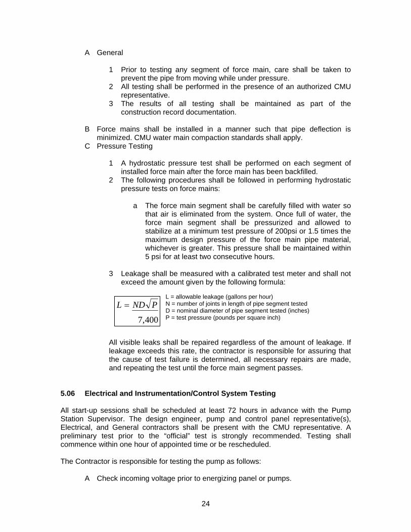
3 Leakage shall be measured with a calibrated test meter and shall not
exceed the amount given by the following formula:
L = allowable leakage (gallons per hour)
400,7
PNDL = N = number of joints in length of pipe segment tested D = nominal diameter of pipe segment tested (inches) P = test pressure (pounds per square inch)
All visible leaks shall be repaired regardless of the amount of leakage. If leakage exceeds this rate, the contractor is responsible for assuring that the cause of test failure is determined, all necessary repairs are made, and repeating the test until the force main segment passes.
5.06 Electrical and Instrumentation/Control System Testing All start-up sessions shall be scheduled at least 72 hours in advance with the Pump Station Supervisor. The design engineer, pump and control panel representative(s), Electrical, and General contractors shall be present with the CMU representative. A preliminary test prior to the “official” test is strongly recommended. Testing shall commence within one hour of appointed time or be rescheduled. The Contractor is responsible for testing the pump as follows:
A Check incoming voltage prior to energizing panel or pumps.
24

B Place the operating mode switch in the off position. C Check motor resistance readings. D Fill wet well with water. E Manually start and stop each pump sequentially and then both pumps
together. F With water level lower than pump’s “shut-off” point, place selector switches in
“auto” position. G Fill wet well slowly and observe lead pump start, pump down, and shut off at
proper level. H Check lead pump motor current. I Increase water level so that lag pump starts, pumps, and shuts off at proper
level. J Check lag pump motor current. K Level control points for lead / lag on and lead/ lag off should be at least 6-
inches apart. L Disconnect power to pumps and fill well to alarm level to verify operation of
visual, audible, and telemetry alarms. Verify that “alarm on” level is at least 6-inches above the “lag on” level.
M Disconnect level controller and verify that pumps are turned on and off at proper levels by the float switches.
N Verify that lead and lag pumps alternate. O Measure pump operating head and “shut-off’ head and perform a timed
drawdown test to verify that actual performance of each pump meets the design criteria.
P Verify that emergency back-up power systems function and will operate both pumps simultaneously.
Q Verify that the UPS system operates the alarm and telemetry systems. R Verify that submersible pumps are properly seated. S Verify the proper time delays between pump starts and adjust, if applicable. T Check other controls as necessary by design. U Test phone and alarm dialer / telemetry alarms and other alarms as required
by design. The results of all testing shall be made part of the construction record documentation. Any changes or modifications will be updated in the O&M manual. 6.00 Submersible Pumping Stations Items not specifically covered in this heading of the specifications are subject to requirements in other sections and in Charlotte-Mecklenburg Utilities’ “Standards and Specifications” as well as the direction of the owner. 6.01 Materials All materials for the pumping stations shall be new and shall be furnished by the Contractor in accordance with the following requirements:
A Pumps: Contractors shall furnish at least two (2) explosion-proof, non-clog submersible centrifugal type sewage pumps designed and manufactured to
25
convey raw unscreened wastewater. The pumps shall be suitable for the physical and chemical properties of the wastewater conveyed and conform to the following:
1 Pump shall be capable of delivering the specified GPM at the
specified total dynamic head as shown on the plans. Pumps shall be as manufactured by Flygt, Ebara, Pumpex, or approved equal. Pump data plate shall be mounted on inside of control panel door and identify the pump manufacturer, voltage, full load amperes, impeller size, pump model, pump serial number, and pump rating (GPM @ TDH).
2 The pump volute, motor and seal housing shall be high quality gray cast iron, ASTM A-48, Class 30 or 35 B. The pump discharge shall be fitted with standard ANSI 125 lb. flanges. All external-mating parts shall be machined and Buna N Rubber O-ring sealed on a beveled edge. Gaskets shall not be acceptable.
3 Bearings and shaft: The pump shaft shall rotate on two (2) permanently lubricated bearings. These shall be heavy duty single or double row ball bearings as needed to provide an American Bearing Manufacturers Association(ABMA) L10 bearing life of a minimum of 50,000 hours at the anticipated axial and radial loadings. Double row sealed grease pack bearings are not acceptable. The pump shaft shall be solid and of a material suitable to the application. The shaft shall be of a sufficient diameter with minimum overhang to reduce shaft deflection and bearing wear. Shaft stiffness factor shall not exceed 60.
4 Seals: Each pump shall have a tandem mechanical shaft seal system. The upper set of tandem seals shall operate in an oil chamber located below the stator housing. The set shall contain one stationary tungsten carbide ring and one positively driven rotating carbon ring, functioning as an independent secondary barrier between the pumped liquid and the stator housing. The lower tandem set shall function as the primary barrier between the pumped liquid and the stator housing. This set shall consist of a stationary ring and a positively driven rotating ring both being tungsten carbide or silicone carbide. Each seal interface shall be held in contact by its own spring system. The seals shall not require maintenance or adjustment, but shall be easily replaceable. The pump shall be equipped with a seal leak detection device and warning system. This shall be designed to alert maintenance personnel of lower seal failure without having to take the unit out of service for inspection or requiring access for checking seal chamber oil level and consistency. There shall be a seal failure sensor installed in the seal chamber between the two tandem mechanical seals or in the stator housing. If the lower seal fails, contaminants which enter the seal chamber or the stator housing shall be detected by the sensor and send a signal to operate the specified warning device. Units equipped with opposed mechanical seals shall not be acceptable.
26

5 Impeller: The impeller shall be enclosed, non-clogging, and have pump out vanes to prevent grit and other materials from collecting in the seal area. The impeller shall be capable of passing a minimum 3-inch solid sphere. Impellers shall have replaceable wear rings. Impellers must be dynamically balanced and shall be slip fit to a tapered shaft and key driven. The impeller shall be fastened to the shaft with a 300 series stainless steel washer and bolt. A volute case wear ring or wear plate shall be provided to minimize impeller wear. The wear ring/plate shall be field replaceable.
6 Motors: The pumps shall have a UL or FM listed, hermetically sealed, air filled submersible type, electric motor for operation at 460 Volt, 3 phase, 60 hertz power. Standard motor speed is 1800 RPM. Horsepower shall be as specified on the plans. They shall be designed for use in electrically hazardous locations (Class 1, Division 1, Group D) and for general use in pumping sewage. The motor shaft shall be stainless steel. The motor shall be provided with thermal overload protection. The motor shall be designed for continuous duty, capable of sustaining a minimum of 10 starts per hour. The combined service factor (combined effect of voltage, frequency and specific gravity) shall be a minimum of 1.15. The motor horsepower shall be adequate so that the pump is non-overloading throughout the entire pump performance curve from shut-off through run-out.
7 Rail Assembly: The pumps shall be mounted on a 304 stainless steel schedule 40 rail assembly with at least two rails and stainless steel brackets. Pump removal shall not require personnel entering the wetwell. A machined metal-to-metal contact shall accomplish sealing of the pump to the discharge connection. The rails shall be plumb and the distance between rail supports shall not exceed 15 feet. The rail/pump interface shall be non-sparking through the use of bronze bushings or other method.
B Wetwell: Precast wetwells shall be 6 feet to 12 feet in diameter constructed
conforming to ASTM C-478. Joints shall be made to receive rubber gasket, butyl mastic rope sealer, and a non-shrink type grout especially made for this purpose. Additionally, all joints shall be coated inside and out with Flex-Seal Utility Sealant by Sealing Systems, Inc, Loretto MN, or approved equal. The sealant coverage shall be 18-inches wide with a minimum dry thickness of 80 mils. Wetwell bottom shall be integrally cast with extended base and walls shall conform to ASTM C-478 or to minimum dimensions shown on the drawings. Wetwell top shall be casted with access doors and pipe penetrations. All exposed concrete finishes for the valve vault and wetwell shall be uniform and finished to a light brush finish after all patchwork is completed. The wetwell shall be installed plumb. Stations with a peak capacity of over 1MGD shall use a cast in place wetwell.
1 Wetwell supplier shall design manhole sections to resist earth loads
and to resist uplift resulting from buoyant forces calculated with groundwater table at finished grades. Wall and/or base dimension shall be increased accordingly.
27

2 Wetwell / Valve Vault Access Door: Shall be constructed of aluminum with ¼” thick one-piece aluminum extruded frame, having a continuous concrete anchor as part of the frame. Door panels shall be ¼” thick aluminum diamond plate capable of withstanding 300 pounds per square foot. All hardware detail and hinges shall be 316 stainless steel with tamper-proof fasteners. Doors shall open 90 degrees and be locked in this position with a stainless steel positive locking arm and aluminum release handle. Doors shall close flush with the top of the frame and be fully supported around the perimeter on a ½” wide lip. Doors shall be lockable with a built in locking point, welded to the frame and have lift assist if weight is over 50 pounds. Doors shall be as manufactured by Bilco, Halliday, or US Foundry.
C Piping: All piping inside the wetwell and through the valve vault shall be
flanged ductile iron pipe with 300 series stainless steel nuts and bolts. There shall be a flexible restrained joint between the wet well and valve vault to prevent damage from differential settlement.
D Valves and Valve Vaults: Valves and appurtenances shall be the type, size
and class shown on the plans and as specified elsewhere in this document. Valves smaller than 4” on pump sewer discharge piping shall not be allowed. Valves shall be located in a separate valve vault. Vaults shall have a 12”x12”x12”deep sump pit along wall nearest the wet well with a 2” sch. 40 304 stainless steel sleeve pipe between the vault and the wet well. This sleeve shall be plugged at each end with common expansion plugs. Swing check valves for pump discharge shall include a ¼” NPT tap in the check valve cover with a ¼” full port ball valve and dust cover.
6.02 Handling and Installation
A All equipment shall be carefully handled and protected from damage while in storage and during installation. Equipment shall be protected from the weather at all times. Equipment damaged by the weather, handling or construction shall be immediately repaired or replaced to the Engineer’s satisfaction.
B Equipment shall be installed in strict accordance with the manufacturer’s instructions and approved shop drawings.
C Equipment manufacturer shall furnish all instructional and assistance necessary for proper installation of all equipment specified herein. After installation, a qualified service representative of the equipment manufacturer shall inspect the complete installation and make adjustments as needed prior to scheduling a CMU representative to witness performance testing, and place the equipment in permanent operation after CMU approval.
7.00 Submersible Pumping Station Electrical Specifications 7.01 General Provisions The Contractor shall furnish all labor, materials, equipment and supplies and shall perform all work necessary for the complete construction of submersible pumping station
28

as shown on the plans and specified herein. Items not specifically covered in this heading of the specifications are subject to requirements in other Charlotte-Mecklenburg Utilities (CMU) “Standards and Specifications” and the direction and approval of the owner. The contractor shall coordinate power and phone service installation in their own name and arrange for the account to be transferred to the City of Charlotte at final acceptance of project. All bills shall be paid current prior to account transfer.
A Applicable Standards, Codes & Design Criteria:
1 All equipment shall meet Standards of Underwriters Laboratories, Incorporated (U.L.) and the National Electrical Manufacturer’s Association (NEMA) in every case where they have established a standard for the particular type of material to be installed. All equipment shall be U.L. listed and labeled.
2 Installation shall meet or exceed the standards established by the National Fire Protection Association (NFPA) as currently referenced under the North Carolina State Building Code (NCSBC). Additionally, CMU facilities shall meet or exceed the requirements of NFPA-820, Standard for Fire Protection in Wastewater Treatment and Collection Facilities.
3 The pump station equipment and installation shall meet the North Carolina Department of Environment & Natural Resources – Minimum Design Criteria (NCDENR-MDC) for the Fast-Track Permitting of Pump Stations & Force Mains. Unless otherwise directed by CMU, and approved by NCDENR, no variance to the Minimum Design Criteria is permitted.
B Installation: Installation shall comply with the applicable rules of the National
Electric Code (NFPA 70), rules/regulations of the SBC and local codes. In no case shall the materials or workmanship fail to meet the minimum requirements of the National Electric Code (NEC). All power and phone lines shall be located within CMU right-of-way and shall be underground within the station enclosure.
1 The regulations of the local electric company shall govern the service
connection and metering provisions. A pad mounted transformer located outside the fenced enclosure is preferred.
C Materials: All materials used in this work shall be new and listed by
Underwriters Laboratory (UL). All nuts, bolts, struts, supports, etc. shall be stainless steel (grade 316 or higher).
D Grounding: The conduit and neutral conductors of the wiring systems and all electrical equipment shall be grounded. The ground connection of the wiring system neutral shall be made at the main service switch or circuit breaker.
1 Grounding electrodes, service ground conductor and equipment
ground conductors shall be furnished and sized in accordance with NEC 250 requirements.
2 All ground conductors running outside of the electrical equipment enclosures, cable trays etc., shall be run in PVC-RGS (Rigid Galvanized Steel) conduit. All conduits shall be bonded at
29

terminations to provide a continuous grounding path in accordance with NEC.
a In addition & supplementary to grounding inherent to
continuous, bonded metallic conduit, a separate equipment-grounding conductor, sized per NEC, shall be installed in each conduit.
3 The grounding electrode connection shall be made below finished
grade with provisions for periodic inspection and adjustment without need for excavation.
7.02 Basic Electrical Materials and Methods
A Wiring: All power & control wiring shall be individual conductors installed in conduit unless otherwise required by CMU or application.
1 Conductors shall be THWN-THHN, stranded copper. Minimum
conductor size shall be #12 AWG for 120-volt (or greater) branch circuits. #14 AWG may be used for control circuits provided it is adequately protected from overcurrent in accordance with NEC requirements. All conductors shall be rated 600 VAC and 75-90°C terminations.
a Motor connections shall be made using insulated multi-cable
connector block (NSI type) connections.
2 Conductors shall run continuous between termination points, and wire-to-wire splicing is prohibited.
3 Contractor installed service, distribution and branch circuit wiring shall be color coded as follows:
a 120/240-volt, 1-phase, 3-wire systems (Serving 120-volt
branch circuits): Phase “A”, black; Phase “B”, red, Grounded neutral, white, ground conductor, green.
b 240-volt, 3-phase, 3-wire systems: Phase “A”, black; Phase “B”, red; Phase “C” blue; ground conductor, green.
c 277/480-volt, 3-phase, 4-wire systems: Phase A, brown; Phase B orange, Phase C; yellow; Grounded neutral, white with stripe, ground conductor, green.
B Conduit Raceways: All wiring, other than those in cable trays, shall be in
PVC- coated RGS conduit manufactured by Robroy or Ocal.
a Conduit size shall accommodate the installed, and/or the anticipated future conductors in accordance with NEC. Minimum size is ¾-inch.
b All conduit connections at enclosures shall be made using Myers STG type, PVC-coated hubs that accommodate bonding. All interconnections between adjacent enclosures shall utilize Myers STG type, PVC-coated hubs; chase nipple
30

connections are not permitted. Only Form 8 style fittings shall be used.
c PVC-RGS conduit shall be installed using specific tools and techniques that do not damage the PVC coating.
(1) Conduits with damaged coatings shall be replaced as
judged by CMU solely. Contractor applied coatings or patching compounds (repairs) are not permitted.
C Cable Tray: A cable tray system shall be furnished for routing wet well power
and control cables to control enclosure. Material and installation requirements are as follows:
1 Cable tray system shall consist of a heavy-duty trough type tray with
solid bottom, louver-ventilated flange type cover and full height barrier strip. Tray, cover & barrier strip shall be constructed of 6063-T6 aluminum alloys.
2 Tray system shall meet all state and local building codes requirements and be listed/labeled for outdoor applications as manufactured by B-line, Chalfant, MP Husky, Thomas & Betts, or approved other.
3 Cable tray shall be sized in accordance with NEC requirements, but shall be no smaller than 12” wide & 4” high.
4 Load rating requirements shall be based on support spans and the anticipated loading (cable weight plus 250 lbs). Load capacity shall be no less than 400 lbs at a span of 6’. Vertical deflection between span supports shall not exceed 1/200th of the span length (>3/8” for a 6’ span). Maximum distance between supports is 6 feet.
5 A full height barrier strip shall be installed over full length of tray system to provide an isolated 2” wide raceway for the intrinsically safe circuit extension cables. Said cables shall be installed, secured and guarded from contact from all other wiring per NEC 504 requirements.
6 Unless indicated otherwise, tray system shall be routed along fence line in areas that will not hinder station access or maintenance operations. Tray system shall be installed no closer than 12” to permit reasonable access for installation/removal of cables, covers & cover clamps.
7 Cable tray shall be installed level (for level lots) or be run parallel to the finished grade (for sloping lots). Where practical, vertical offsets should be made using standard, factory assembled inside & outside vertical bends. Offsets that do not correspond to those possible with factory-assembled fittings may be achieved using hinged splice plates.
8 Horizontal bends shall be factory assembled; no field modifications will be allowed.
9 Covers shall be segmented in 3’ sections (where possible) and cover clamps installed at intervals not exceeding 3’. No less than two clamps shall secure a cover segment.
10 Tray system shall be elevated 8” above finished grade on cylindrical or rectangular reinforced concrete piers with 1-5/8”, 316 stainless steel channel grouted into support pier. Tray shall be attached using resilient mounts (guide clamps), and expansion type fittings shall be
31

installed at section joints, as necessary to alleviate stresses due to thermal expansion intermittent loading.
11 Tray system shall have adequate provisions for cable drop-in (at panel) and dropout (at wet well). Cable shall be adequately protected & supported. Contractor shall maintain adequate separation for intrinsically safe cables in accordance with NEC 504.
a Tray section below control panel shall be terminated using
blind end plate with 3-sided bushed opening in cover to permit cable drop-in from control panel. Cables entering control enclosure shall be terminated using cable seal fittings in accordance with NEC 501-5(d)(1).
b A 4” radius dropout bushing shall be installed at cable entrance to wet well. Tray system shall be extended over wet well opening and be terminated with a blind end plate. Strain relief devices (stainless steel, wire mesh cord grips) shall be installed where cables enter wet well.
D Electrical Service Entrance Equipment: A U.L. Service Entrance listed
disconnecting means shall be provided as follows:
1 Disconnect enclosure shall be NEMA 4X, heavy-duty type constructed of stainless steel. Contractor shall clearly label disconnect enclosure with the Service Voltage & Phase. Label plate shall be engraved phenolic permanently cemented, using 2-part, marine epoxy, to the front surface of the enclosure.
2 Disconnect shall be furnished with all necessary grounding and neutral connection kits required for installation and/or service entrance listing. Where terminations of multiple phase, neutral or ground conductors is necessary, equipment shall have the proper multi-barrel lugs to accommodate them.
3 Disconnect shall have overcurrent protection provided integral (breaker type) or located within disconnect enclosure (fusible) as indicated below:
a Where approved by NCDENR (on a case-by-case basis) a
thermal magnetic type circuit breaker shall be used for the service disconnect.
b For NCDENR-MDR, fully compliant installations, a fusible switch shall be used for the service disconnect.
E Concrete Equipment Pads: Concrete Pads shall be furnished below all
electrical equipment racks or as mounting surfaces for freestanding enclosures or generators. Pad shall be located and oriented such that all electrical enclosures will remain outside any NFPA 820 designated hazardous area. Hazardous areas for all CMU wastewater-pumping facilities shall be based on a non-ventilated “combined” or “sanitary” sewer (NFPA 820, Table 2, Row 16a); “Residential” wastewater classification (Row 11a) shall not be used.
32

1 Pads shall be furnished to accommodate equipment load without cracking or settling, but in no cases shall they be less than 3600psi concrete; 10” minimum thick with 6x6/W1.4xW1.4 welded wire mesh reinforcement. Final elevation shall be 8” above grade. Pads at electrical racks or enclosures fully accommodate full width of enclosure & rack installation with 6” additional space on each side, and a minimum 3’6” in front of deepest cabinet and shall extend at least 6” behind enclosures.
2 Pads shall be formed with two or more access windows to permit stub-ups for electrical/communications connections in control panel, generator/transfer switch or service equipment.
3 Equipment pads shall have light brush (non-skid) finish and all edges, including those for wiring access, shall be chamfered.
F Auxiliary Mounting rack: A steel mounting rack shall be provided at all
facilities equipped with permanent generators for mounting of service disconnect, automatic transfer switch, telephone service terminal & other appurtenances not integral or attached to a freestanding enclosure. Rack & enclosures shall be located outside all hazardous areas (see mounting pad requirements above). Rack components and installation shall comply with the following:
1 Horizontal support members shall be constructed of 1-5/8” stainless
steel, channel (Unistrut #P1100 or approved equal). Structure width shall be sufficient to accommodate mounting of designated equipment.
a Enclosures shall be mounted using stainless steel spring nuts
& bolt connections at the enclosure’s mounting bushings or brackets.
b Supports shall be mounted level and square to vertical posts using 3/8” stainless steel U-bolts, nuts & washers. The open side of the Unistrut channel shall face away from posts.
c Install protective end caps on all channels.
2 Vertical posts shall be furnished and installed as follows:
a Posts shall be constructed of 3” ID rigid galvanized steel conduit and shall extend from 6’6” (max) above finished grade and 2’6” minimum below finished grade. Tops shall be sealed using threaded sleeves and insert plugs.
b Post shall be embedded in ground and ballasted with concrete (minimum 60lbs per post) to provide a rigid and plumb support for electrical equipment. Additional supports, embedding depth or ballast material shall be provided as necessary to maintain a plumb & square installation.
7.03 Pump Station Electrical Equipment & Installation All materials for the pumping stations shall be new and shall be furnished by the Contractor in accordance with the following requirements:
33

A Pumps & Floats: Contractor shall furnish two (2) non-clog submersible
centrifugal type pumps with electrical characteristics as follows (See Civil specifications for pumping and construction requirements):
1 Pump Motors: The pumps shall have a UL or FM listed, hermetically
sealed, air filled submersible type, electric motor for operation at 460 Volt, 3 phase, 60 hertz power. They shall be designed for use in electrically hazardous locations (Class 1, Division 1, Group D) and for general use in pumping sewage. The motor shall be provided with thermal overload protection and a moisture detection system.
2 Motor & Float cable: Assemblies shall be UL approved for extra-hard usage and shall be of sufficient length to reach the control panel without the need of any splices. Where required by local authorities, each cable shall contain a grounding conductor in addition to any circuit conductors. Outer covering shall be oil resistant, thermoplastic. Conductor size shall be per NEC standard requirements.
B Pump Control System:
1 General: It is the intention that this specification shall cover a
complete Electrical Pump Control System as hereinafter described and all necessary appurtenances that might normally be considered a part of the complete electrical system of this installation. All of the automatic control equipment is to be furnished by one manufacturer and supplied by the pump manufacturer. It shall be factory assembled, wired, and tested. Complete electrical drawings and instructions shall be submitted for approval.
2 Required Submittal Information
a In order for a system to be considered, it will be necessary for the contractor to provide three sets of written information completely describing the system. Should the system or the information describing it fail to describe its capability in meeting the job requirements or if the contractor fails to furnish complete information, the engineer shall regard the submittal as an inferior system and disregard the submittal.
b Electrical Contractor shall submit product information for all materials that will be used in the installation and interconnection of pumping system equipment. Such items shall include, but are not necessarily limited to: electrical wiring, conduits, fittings, cable tray, mounting struts, etc.
c This information shall include complete mechanical dimensions, electrical details and specifications of every electrical device, valve, meter and instruments to be provided by this section. If a microprocessor or any other similar programmable system is being provided, manufacturer’s literature shall be provided.
d System sketches shall be provided of the hydraulic processes identifying the locations schematically of all process equipment being provided by this contract and the schematic location of
34

the devices being provided in relation to the process equipment.
e A written system description of how the control system interacts with the process equipment shall be provided. A system schematic shall be provided indicating the relationship of telemetry equipment to the system. A sketch shall be provided of the main control panel indicating enclosure size and relative location of panel mounted equipment. All panel-mounted equipment is to be identified on this panel sketch so that their existence can be checked and functional relationships determined and wire routing can be verified.
3 Field Supervision: The services of a factory trained, qualified
representative shall be provided to inspect the completed installation, make all adjustments necessary to place the system in trouble free operation and instruct the operating personnel in the proper care and operation of the equipment.
4 Guarantee: All equipment shall be guaranteed against defects in material and workmanship for a period of one year from date of owner’s final inspection and acceptance to the effect that any defective equipment shall be repaired or replaced without cost or obligation to the owner.
5 Wiring: All wiring shall be of a single manufacturer. It shall be stranded, minimum 600-volt (UL) type MTW or AWM and have a current carrying capacity of not less than 125% of the full load current. The conductors shall be in complete conformity with the National Electric Code, state, local and NEMA electrical standards.
a Wire ID Labeling: To ensure the safety of personnel and aid
circuit tracing or troubleshooting efforts, all wiring shall be affixed with permanent ID labels at every termination. Application of ID labels shall be in strict accordance with the manufacturers wiring diagram. ID labels shall be pre-printed, heat-shrink sleeves (closed tube type). Wrapped tape or tag type labeling is not acceptable.
b Color Codes: All control/signal wiring shall be color coded as follows:
(1) “Normal” powered (hot) conductors, red; neutral
(common) conductors, white. (2) “Emergency/UPS connected” powered (hot)
conductors, purple; neutral (common) conductors, white.
(3) Dialer alarm conductors shall be yellow.
6 U.L. Approval, Listing & Labeling: The control panels shall be constructed in compliance with Underwriter’s Laboratories “Enclosed Industrial Control Panels Relating to Hazardous Locations with Intrinsically Safe Circuit Extensions” (UL 698) listing and follow-up service, utilizing UL listed and recognized components where
35

applicable. The control panels shall bear the Underwriter’s Laboratory listed & serialized label.
7 Control panel Enclosure: The described equipment shall be housed in individual UL Type 3R stainless steel enclosures arranged for integral pedestal mounting where shown on the drawings. The enclosure shall be approximately 60” high, 12” deep and sufficiently wide to house control panel components & accessories. Enclosure shall have no pumping eyes or other nonessential penetrations.
a The enclosure shall be constructed of not less than 14-gauge
stainless steel and suitable for installation in an unprotected outdoor location. It shall have a gasketed, hinged front weather door with three-point latching mechanism and padlockable handle.
b Data pockets shall be mounted to interior panel doors with bolts on welded steel anchors as follows:
(1) One 6” wide X 6” high X 1” deep data pocket shall be
installed on front side of the inside door. Locate data pocket below elapsed time meters.
(2) One 12” wide X 12” high X 1” deep data pocket (for O & M manuals) shall be installed on the backside of the inside door.
c Control enclosure shall incorporate a hinged, dead front panel,
behind the weather door such that all controls and meters necessary for routine operation are accessible without exposing the internal components and circuitry.
d All major components and sub-assemblies shall be identified as to function with laminated, engraved phenolic nameplates or similar approved means. A 12” X 18” laminated control panel print shall be permanently bonded to the backside of the exterior door. Pump data plate shall be mounted on inside of panel door identifying the pump manufacturer, voltage, full load amperes, impeller size, pump model, pump serial number, and pump rating (GPM @ TDH).
e Equipment control panels shall be sheltered by a white aluminum awning structure extending one foot beyond the back and sides and three feet to the front of the control panel. In no case shall the awning be smaller than the concrete slab for the equipment rack. See standard detail 6.
8 Power Supply and Metering
a The incoming service shall be as noted on the drawings. All
metering shall be done ahead of the main disconnect and control panel.
b Control panel shall have an emergency battery backup system (UPS) to operate the local alarm light and horn for at least 120 minutes. Additionally, this backup power source shall power the intrinsically safe relay module monitoring the high wet well
36

float such that a high level condition will be recognized and reported by the telephone dialer during losses of power and/or failure of on-site power back-up systems.
c UPS power output shall be isolated during normal operation such that UPS failure cannot effect the normal operation of the pump station. UPS output shall be connected via a maintenance by-pass switch to allow easy maintenance, removal or replacement of the UPS.
9 Pump Circuit Breaker & Branch Circuit Breakers:
a Symmetrical RMS fault current ratings for all circuit breakers
(operating at service voltage) shall be coordinated to no less than maximum fault current availability from electric utility. Breakers serving pumps/motors shall be equipped with padlock hasp for lockout capability.
b All circuit breakers shall be heavy-duty type with handles operable through the inner door. Circuit breakers shall be properly sized to protect equipment and wiring from overcurrent conditions.
c Sufficient 120-volt, branch circuit breakers & transformer capacity shall be provided to serve all pump station appurtenances. Branch circuit breakers shall have fault current ratings of 10,000 amps symmetrical or greater. Branch circuit loads include, but are not necessarily limited to, the following:
(1) GFCI outlet, Condensation Heater & Area Light (2) SCADA System (Future) (3) ½ hp Sump Pump (Future) (4) Electronic Control module (5) Block Heater (6) Battery Charger (7) Dialer & UPS input (8) Spare circuit.
10 Three Phase Voltage Monitor: A Three Phase Voltage Monitor shall
be provided in control panel. Unit shall protect against phase loss, phase reversal and under voltage. Unit shall be fully adjustable and wired for offsite monitoring capability. Unit shall have automatic restart capability along with adjustable restart delays. Dialer shall be provided with (2) Form C contacts (to disable motors & alarm condition reporting via dialer).
11 Motor Starters: A motor starter shall be provided for each submersible pump motor. Overload devices shall be selected (or adjusted) based on nameplate data of installed pump. Coil voltage and pump controls shall be 120-volt. Depending on pump size, starters will be NEMA rated, Full Voltage, Non-Reversing (FVNR) magnetic type or solid state, “Soft-Start” units as indicated:
a FVNR motor starters shall be furnished for pump motors up to
20hp (unless otherwise directed by CMU, or required by local
37

electric utility). Starters shall have ambient insensitive, thermal overload relays with manual reset.
b Soft-Start starters shall be provided for all pump motors exceeding 20hp. Starters shall be optimized for centrifugal pumping loads and equipped with integral shorting contactors (to by-pass Silicon Control Rectifier (SCR) circuit after start-up for increased efficiency & reduced heat build-up). Benshaw, Inc is the only approved manufacturer for the soft-start unit. Starter shall have adjustable, electronic motor protection/overload relay with auxiliary contacts for telemetry annunciation of pump failure.
12 Pump Data: The motor HP, full load amps, circuit breaker size, and
motor starter size shall be shown on the vendor’s shop drawings. 13 Control System: A packaged digital control system shall be furnished
to monitor wet well levels and generate outputs for stop/run operation of two or more submersible pumps. System shall be equipped with an integral bubbler system providing analog output (for SCADA) and programmable start/stop/alarm indications & outputs for integration into the motor control circuits and/or local alarm/telemetry equipment. System shall have input connections for two (or more) backup floats. If bubbler system should fail, pumping operations will continue automatically via float level sensing. The electronic control system shall be by Digital Control Corporation (DCC) (part & specification numbers #11928 & #DS11928I respectively) or MultiTrode/Flygt Model MT2PC.
14 Level Float Switches: High and low level float switches shall be installed to provide redundant level sensing to the control system for backup operation when bubbler system is off-line. Floats shall be wired via U.L. 913 listed, intrinsically safe control relays. All intrinsically safe wiring, terminals and components, shall be installed in accordance with the requirements of U.L. 698. All contractor installed connections & equipment shall be installed in full compliance with NEC 504.
15 Bubbler Tubing & Connections: Bubbler Tubing shall be 3/8” OD with 40 mil wall thickness. Tubing shall be black thermoplastic polyethylene. Tubing from panel through tray shall have no low points that may allow condensation to collect. Connections shall be made using flairless fittings of brass or stainless steel; “push-to-connect” type fittings are unacceptable.
16 Running Time Meter: A running time meter measuring hours and tenths of hours of operation up to 99999.9 hours shall be furnished for each pump motor indicated. This shall be a 120 VAC device operating from the control voltage by an auxiliary contact of the motor starter or other run contact.
17 Selector Switches: A heavy-duty, three-position, hand-off-automatic selector switch shall be flush-mounted on the inner door of the control center for the operation of each motor magnetic starter. This selector switch shall operate the starter when it is in either the “hand” position or the “automatic” position and the automatic control system is calling for the operation of the equipment in the manner as herein described.
38

18 Status Indicators: Status indicator lights shall be incandescent only, furnished and mounted on the inner door as follows:
a Red pilot light indicating wet well “high level”. b Red pilot light indicating wet well “low level”. c Green “pump running” indicator lamps. d Red “Over Temperature” indicator lamps. e Amber “Pump Seal Failure” indicator lamps.
19 Enclosure Heaters: 120-volt protective heaters (for condensation
prevention) with high temperature safety switch shall be supplied in the control panel. Heater wattage, quantity and placement shall be determined by panel manufacturer to suit panel volume and anticipated site conditions.
20 Weatherproof Alarm Light: A weather proof, high water alarm light assembly including a high impact resistant lexan red lens shall be included. The alarm light bulb shall be replaceable from inside the control panel without having to remove the weatherproof red lens from the panel. A solid-state flasher shall be included to strobe the alarm light for any of the specified alarm conditions.
21 Weatherproof Alarm Horn: A weatherproof audible alarm horn shall be provided. The horn will be side mounted to the control center and operate on 115 VAC with a typical 95 dB output. An alarm silence push button shall be included, mounted on the inner door.
22 Solid-State Telephone Dialer: Telephone dialer shall be furnished integral to control panel. Dialer shall have an assignable channel capacity of 16 and cellular phone back-up. Manufacturer/model shall be Antx,Inc./DiaLog Elite. Additional requirements are indicated below:
a Dialer shall have internal reporting for loss of AC power input.
This capability shall be intrinsic to the device and should not require additional connections or the use of any assignable channels. Dialer shall have a published operational temperature range between -5° & 130°F.
b Upon detection of any alarm or status unit shall commence dialing up to 16, 10-digit, telephone numbers from a list associated with the particular alarm condition or combination thereof, and deliver a voice message describing the alarm condition(s).
c Message shall be a digitized human voice using channel specific vocabulary messages recorded by user. Once alarm receipt is positively acknowledged, (by keyed-in code), unit will enter a user programmable time-out mode, after which time, if the condition has not been addressed & corrected, the dialup operation will resume.
d Unit shall have data logging capability, showing alarm conditions along with time/date stamp. Unit shall be capable of downloading such information to a printer via an integral RS-232C (parallel) printer port.
39

e An integral battery back-up power system shall have sufficient capacity to operate dialer for 16 hours (minimum) at full load (worst case) conditions.
f Unit shall have capability of functioning in as an intercom allowing the called or calling party to “listen-in” on the monitored environment (after satisfying the security access code).
g All alarm channels shall be programmable to accept either normally open or normally closed contacts. Dialer channel inputs shall be accept “dry” contact closures for monitoring alarm conditions as follows:
(1) Power failure (internal to dialer) (2) (CH 11) High level (electronic control system alarm set
point) (3) (Ch 12) High level (float switch via intrinsically safe
relay) (4) (CH 13) Low level (electronic control system alarm set
point) (5) (CH 14) Low level (float switch via intrinsically safe
relay) (6) (CH 15) Power problem (7) (CH 16) Overload Alarm Pump #1 (8) (CH 17) Overload Alarm Pump #2 (9) (CH 18) Pump 1 (thermal failure) (10) (CH 21) Pump 2 (thermal failure) (11) (CH 22) Pump 1 (seal failure) (12) (CH 23) Pump 2 (seal failure) (13) (CH 24) Generator failure (14) (CH 25) Generator running (15) (CH 26) Emergency power “ON” (ATS) (16) (CH 27) SPARE (17) (CH 28) SPARE
h Dialer shall be configured with a 3-watt analog cellular phone operating over the Advanced Mobile Phone System (AMPS). The dialer shall be capable of voice and data communication with calls originating from the dialer or an outside source. The DiaLogOnline internet service shall operate with the dialer over a cellular phone connection. Dialers shall operate using a landline or analog cellular phone without programming modifications. Cellular phones shall be equipped with an external directional antenna, surge protection, 120VAC power supply, back-up battery, and integrated battery charger. Cellular phones shall be mountable on a sub-panel and connect to the dialer through a single modular phone jack connection. The directional antenna shall provide a minimum of 6dB gain in the 824-896 MHz frequency range. Antennas shall include an N-type female connection, lightning surge protection, and a minimum of 20 feet of cable.
40

7.04 Spare Parts The manufacturer is to furnish a list of all recommended spare parts including at a minimum two sets of fuses, indicator lamps and gaskets. The spare parts shall be provided, together with service manuals, prior to start-up date. 8.00 Emergency and Standby Power Systems 8.01 Systems The system shall be provided complete with all necessary automatic starting equipment, transfer switch, fuel tank, supply and return fuel oil piping, exhaust system/silencer, generator output circuit breaker, and all other necessary appurtenances for complete and operable system. 8.02 Products
A Engine Generator Set: The Generator, consisting of a performance matched diesel engine and electrical alternator, (see engine & alternator below) shall be the product of Caterpillar, Kohler, or Cummins.
1 The distributor must be authorized to perform warranty work on both
the engine and generator. The distributor shall have factory-trained service personnel under their direct employ.
2 Supplier must have no less than sixty percent of all generator replacement parts in his stock at all times. Certified proof of this requirement shall be available from the distributor.
3 Generator capacity shall be sufficient to power all connected loads. Size shall be based on a 2-step generator loading sequence; Step #1 = “lead” pump & all appurtenances, Step #2 = “lag” pump. Acceptable performance under installed conditions shall be as follows:
a Starting voltage dip shall not exceed 30%. b Steady state voltage shall be maintained within +/-0.25% from
no load to full load. c Steady state frequency regulation shall be +/-0.33% with a
frequency dip of less than 5% from no load to full load.
4 Generator set capacity shall not be greater than 30% of fully loaded pump station facility.
5 The complete operating system, including engine generator set, accessories, and transfer switch, shall be furnished to the Contractor by one vendor as a single, complete package to assure system responsibility and that vendor shall be the local factory authorized distributor of the engine company.
6 Generator shall be furnished in weatherproof enclosure. Batteries shall be located inside a weatherproof enclosure separate from main enclosure.
7 Generator shall be equipped with an NFPA 110, 12-light monitor and meter package as indicated below:
41

a AC volt/ammeters w/phase selector switch. b Dual scale frequency/tachometer c A/C rheostat with ±5% output voltage adjustment. d Light indicators w/alarm contacts as follows:
(1) Generator run (green) (2) Low oil pressure alert (yellow) (3) High coolant temp alert (yellow) (4) Low oil pressure alarm (red) (5) High coolant temp alarm (red) (6) Overcrank shutdown (red) (7) Overspeed shutdown (red) (8) Switch Off, Auto-start mode off (flashing red) (9) Low coolant temp (yellow) (10) Low fuel (yellow) (11) Two (2)Auxiliary fault indicators (red lights)
(a) Fuel leak detection (b) Unused spare indication
Alarms 2 through 11 shall be tied to a common failure alarm and routed to the control panel dialer as a “generator failure” - channel 13.
B Engine: The engine shall be the product of Caterpillar, Kohler, or Cummins and shall be a model that has been manufactured and successfully operated for a period of one year.
1 The engine shall be of the four-cycle type, multi-cylinder, and capable
of starting solely on No. 2 diesel fuel. The engine shall develop its respective rated horsepower at 1800 rpm. Rating shall be in accordance with the requirements of the Diesel Engine Manufacturer's Association of 85-degrees and elevation of 1500-feet.
2 Maximum or gross engine horsepower to produce standby generator KW ratings is unacceptable. Minimum engine horsepower at 1800 rpm will be determined by the formula below:
( )[ ] MFACCRFEFFKWHP +++×÷= 746.0 Where, HP = Minimum Engine Horsepower KW = Generator Rating in Kilowatts EFF = Gen-Set Efficiency RF = Radiator Fan Horsepower ACC = Accessory Horsepower MF = Manufacturing Tolerance
42

3 The engine shall be equipped with a 12 or 24-volt electrical starting system capable of starting cold on No. 2 diesel fuel. Engine shall automatically start on power failure and transfer to standby power and retransfer to normal power upon restoration. Engine shall be equipped with all auxiliaries recommended by the Manufacturer for proper, sure, quick starting of the engine including coolant heater as a cold weather starting aid.
4 Engine shall be liquid cooled via fin-tube radiator and engine driven blower fan. Radiator shall dissipate full load engine heat at a 110-degree F ambient temperature using a 50% ethylene glycol solution. Radiator top tank temperature shall not exceed 205°F.
5 Engine shall be equipped with an adjustable isochronous type electronic governor with stalled work capacity 50% greater than required. Governor shall be Woodward 2301 or equal by Barber Coleman.
6 Combustion exhaust shall be routed via a critical or hospital grade silencer and terminated with a hinged rain cap. Silencers furnished integrally with the sound attenuating weather housing are equally acceptable.
C Alternator: Alternator shall be the product of an established generator
manufacturer and shall be a model that has been manufactured and successfully operated for a period to sufficiently establish its reliability.
1 Design shall be revolving field, single bearing, 4-pole, brushless, drip-
proof construction. Temperature rise shall be no greater than 130°C at rated output.
2 Output shall be reconnectable, 12-lead type. 3 Excitation system shall employ a Permanent Magnet Generator
(PMG) and shall provide 300% short circuit capacity for a 10 second duration to provide a reliable source of excitation power for optimum motor starting and short circuit performance.
D Batteries & Charger: Heavy-Duty lead-acid batteries and charger shall be
provided with generator and mounted within weather enclosure.
1 12 or 24-volt battery system shall be provided to match engine cranking system. Capacity shall be for at least three cranking cycles (each cycle consisting of three 10-second cranks with five-second rest period between each crank), total cranking time of 160 seconds.
2 An automatic "float" type battery charger shall be provided to maintain the batteries at normal capacity and to recharge batteries after cranking.
a The charger shall have fused 120-volt input with fused 12 or
24-volt output with ammeter/voltmeter displays. b Regulated DC output with complete isolation from A.C. input to
prevent battery in event of failure. c Unit shall be capable of recharging a completely discharged
battery in eight hours or less. d The charger shall be U.L. listed and labeled.
43

E Sound Attenuated Housing: A weather enclosure with noise attenuation
features shall be furnished to limit the combined engine & exhaust noises produced by the generator. All generator installations shall limit noise to 75 dBA (average readings taken at 8 positions, measured 23’ (7m) from unit centerline in a free field environment).
F Automatic transfer switch (ATS): ATS shall be enclosed contactor type unit. Unit shall be continuous rated for all load types and furnished with all necessary contacts, relays and accessories required for proper operation. Transfer switches utilizing molded case or insulated case circuit breakers shall not be acceptable.
1 ATS enclosure shall be weather/corrosion resistant stainless steel
with UL-3R (or NEMA 4X) listing. 2 ATS control shall be such that the engine shall continue to run for five
minutes after retransfer to normal power and then shut down. 3 ATS shall be furnished with 7-day exerciser clock for unattended
exercising of engine. 4 Auxiliary control and status contacts shall be furnished for generator
starting, shutdown & off-site monitoring.
G Low-Profile Platform or Sub-Base Fuel Storage Tank: Fuel storage tank of capacity indicated on drawings shall be of double-wall construction to provide secondary containment of fuel in the event of a weld, seam or other failure in the storage sections of the tank. The secondary containment shall provide at least 10% of the storage tank capacity. Tank capacity shall be of sufficient to provide no less than 24 hours of operation at the generator’s full rated load. All materials shall be new and rust free and shall meet ASTM A36 Standards. On smaller units, sub-base type tanks are permitted if no generator controls, meters or breaker handles will be more than 6’ above finished grade. For larger generators, a platform type tank shall be furnished providing a non-skid standing surface (18” minimum width) around the perimeter of the generator’s weather housing. The overall enclosure should not be more than 8 feet in height.
1 Tank design shall incorporate structural steel channels or I-beam side
rails common to both the fuel tank and the secondary confinement. Top and bottom of both the fuel tank and secondary confinement sections shall be 10-gauge minimum sheet steel. Secondary confinement section of tank shall have a minimum depth of three inches.
a All internal cross members shall be sized to support the
specified generator and all necessary appurtenances. Cross members shall be designed to allow free and equal flow of fuel through the storage tank and the secondary confinement section.
b A "stub-up" sleeve shall be provided through both the main fuel tank and secondary confinement section. Sleeve shall be 12-inches square and shall not compromise the secondary
44

containment criteria. Sleeve shall be located below the output circuit breaker and generator control panel.
2 Construction of the tank shall be in two steps. The fuel tank section
shall be constructed, deburred and pressure tested. The secondary containment section then shall be constructed, deburred and pressure tested.
a Pressure tests shall be at 10 PSI minimum. Any defects shall
be repaired and retested. b All welds shall be continuous MIG or dual shield type.
3 The tank shall be equipped with the following fittings and
appurtenances:
a 2-inch N.P.T. manual fill pipe with cap located outside of enclosure.
b Mechanical fuel level sight located to allow monitoring during filling and to prevent over filling.
c Fuel supply and return fittings. Flexible fuel lines shall be provided between tank and engine.
d 3/4-inch N.P.T. vents with screened mushroom caps shall be provided for fuel storage and secondary containment sections of the tank.
e A leak detection device mounted in the secondary containment section of the tank with dry contacts for annunciation at the engine panel shall be provided.
f Provide low fuel alarm contacts to indicate at the engine panel when there is only three hours fuel remaining in the tank.
8.03 Execution
A Shop Drawings, Manuals & Submittals: Drawings, details, and instructions necessary for installation of the generating unit and accessories shall be submitted prior to the purchase of any equipment. Such documents shall indicate compliance with performance specifications for loads served. The Contractor shall furnish operating and maintenance instructions and manuals and dimensional drawings.
B Personnel instructions: Provisions shall be made for instruction of Owner's operating personnel during the construction period, and a concentrated instruction course during the final check and acceptance test stages.
C Field tests: The engine generator sets shall first be broken in, in accordance with the recommendations of the Engine Manufacturer, and all safeties checked. After this the set shall be run two hours at 75% rated load, and then immediately after by two hours at 100% rated load. Voltage performance shall be verified. Any problems or deficiencies found shall be corrected and test repeated until satisfactory. All required instrumentation for testing shall be provided.
D Fuel: Upon installation of the tank, the Electrical Contractor shall fill the tank with diesel fuel and refill the tank at completion of testing and operation just prior to acceptance of the Project.
45

8.04 Guarantee and Service
A Guarantee: All equipment and wiring shall be guaranteed against defects in materials and workmanship for a two year period from the activation of the system.
B Service: the Manufacturer’s factory trained service representatives shall perform all service.
1 Routine warranty service for the equipment will be performed during
normal working hours, (Monday thru Friday, 8:00 a.m. to 5:00 p.m., excluding City of Charlotte holidays). Emergency service provided at times other than stipulated above shall be provided from the same source at no additional cost to the Owner.
2 The Manufacturer shall have a service facility within 120 miles of the Charlotte CBD with effective dispatching to assure a maximum two-hour on-site response to the Owner's request for service. The Manufacturer shall demonstrate this capability to the Owner and shall provide this minimum response under all reasonable circumstances.
3 Upon satisfactory completion of all tests the Manufacturer's representative shall present to the Owner a proposal to provide semi annual inspection, service and testing of the system.
46