Embed Size (px)
Citation preview

V01.1 1
Introduction Wash & Clean systems for the food processing industry is an utility application that sets high requirements for the pump system, due to limited available space, harsh environment and operating pattern. The pumps used for this application are often compact pumps built into cabinets, portable units or mounted on skids where space always is an issue. The locations are often damp or wet due to wash down, and ambient temperature can vary between cold and warm over an operating cycle. The pumps are typically operated for an hour a day and left on standby for the rest of the time. During the cleaning cycle the pumps shift between full flow and no flow, and at various discharge pressure. The pumped liquid can be cold or hot water that after the pump are combined with disinfectant, detergent and other chemicals. Dosing pumps, ejectors, compressors and air‐injectors are integrated parts of the installation. The primary requirement to wash and cleaning equipment is efficient cleaning at shortest possible time. Wash and Clean applications calls for an advanced compact pump setup that can adjust quickly and accurately to the changing demands and operate under challenging conditions. It is important to design the system with the pump as an integrated part, and by utilizing the functions and features in the pump it is possible to reduce the physical footprint and save external components, so already at an early state of the design process extend the perspective beyond the pump and look at the whole system/unit.
Table of contentIntroduction ................................................................ 1
Purpose ....................................................................... 2
Application Characteristics ......................................... 2
Solution ....................................................................... 3
Run at power limit ...................................................... 4
Pumps ......................................................................... 5
Motors ........................................................................ 5
Protection ................................................................... 6
Stop at no flow – Stop function .................................. 7
Considerations and limitations ................................... 8
Industrial washer systems .......................................... 9
Wash and Clean By Michael Rasmussen, Industry application team, Grundfos, Denmark
V01.1 2
Purpose The purpose of this Paper is to present some of the features that can be incorporated in a compact, efficient customized wash and clean system. It will explain the benefits of using pumps with integrated frequency converters (E‐motors) and options for monitoring, system protection and control of external equipment. The E‐motors are developed along with our presence in the wash and clean business as preferred supplier of customized pumps, and a lot of the functions and features are targeted towards that application.
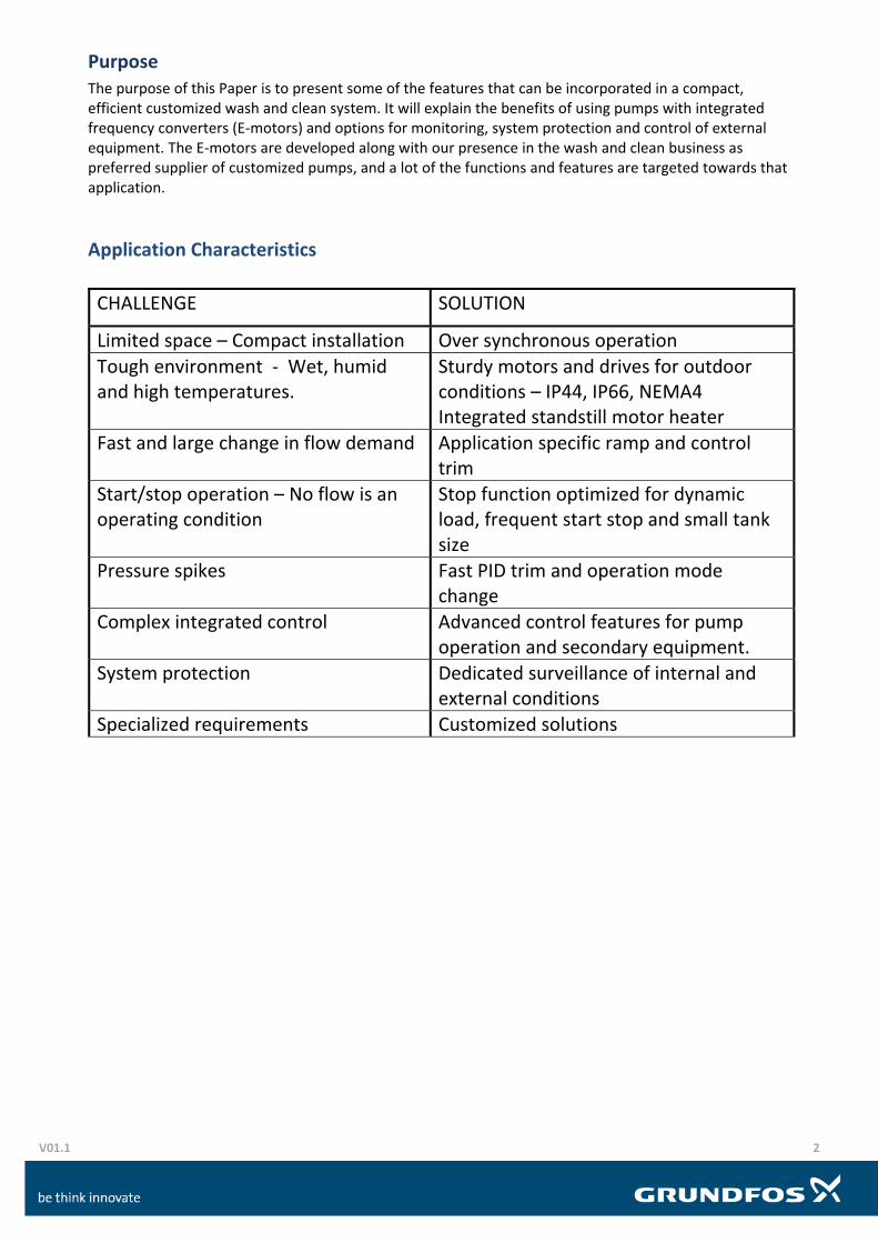
Application Characteristics
CHALLENGE SOLUTION
Limited space – Compact installation Over synchronous operation
Tough environment ‐ Wet, humid and high temperatures.
Sturdy motors and drives for outdoor conditions – IP44, IP66, NEMA4 Integrated standstill motor heater
Fast and large change in flow demand Application specific ramp and control trim
Start/stop operation – No flow is an operating condition
Stop function optimized for dynamic load, frequent start stop and small tank size
Pressure spikes Fast PID trim and operation mode change
Complex integrated control Advanced control features for pump operation and secondary equipment.
System protection Dedicated surveillance of internal and external conditions
Specialized requirements Customized solutions

V01.1 3
Solution
Wash and cleaning systems for the food processing industry operate in different pressure levels, 20 – 40 – 60 – 80 Bar, where Grundfos mainly supply centrifugal pumps for the 20 and 40 bar pressure range. For a centrifugal pump operating at 3000 or 3600rpm to generate 20 – 40 bar requires relatively many stages and thereby a rather tall pump. The wash and clean equipment is usually built into carts that are hauled around in the facility or wall mounted cabinets installed in the wash down environment. That calls for compact pumps that can deliver high pressure, and operating at over synchronous speed is a good solution to that challenge. The affinity equations apply with close approximation to the change of speed of centrifugal pumps: By changing speed from 3000rpm to 4500rpm, the pressure increases 2,25 times, Going from 3000rpm to 6000rpm will deliver 4 times more pressure. CRE3‐9 is a small pump that often is customized for high speed mounted with a 4kW E‐motor operated at 5800 rpm ‐ delivering the same performance as a CRE5‐36 The pumps are factory configured with a smaller fan to reduce noise and reinforced chambers and impellers to handle the higher pressure. The pump end length is reduced to less than 1/3.
H = head in m, Q = flow rate in m3/h, P = input power in kW, n = speed.
CR5‐36 3000rpm/5,5kWCR3‐9 5800rpm/4,0kW
CRNE3‐94,0 kW
5800 rpm
CR
3-9
393
mm
CR
5-36
12
53m
m
Pump End Length
V01.1 4
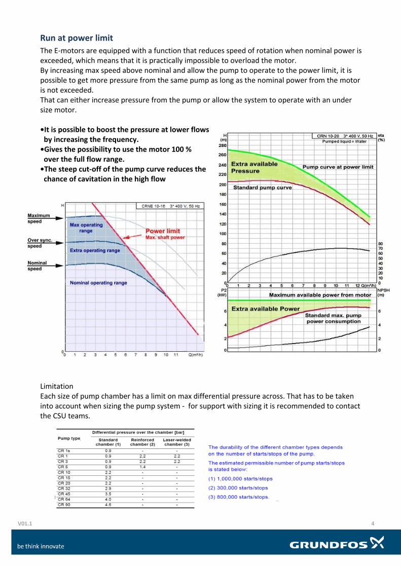
Run at power limit
The E‐motors are equipped with a function that reduces speed of rotation when nominal power is exceeded, which means that it is practically impossible to overload the motor. By increasing max speed above nominal and allow the pump to operate to the power limit, it is possible to get more pressure from the same pump as long as the nominal power from the motor is not exceeded. That can either increase pressure from the pump or allow the system to operate with an under size motor. •It is possible to boost the pressure at lower flows by increasing the frequency. •Gives the possibility to use the motor 100 % over the full flow range. •The steep cut‐off of the pump curve reduces the chance of cavitation in the high flow Limitation Each size of pump chamber has a limit on max differential pressure across. That has to be taken into account when sizing the pump system ‐ for support with sizing it is recommended to contact the CSU teams.

V01.1 5
Pumps
Grundfos offers a large range of pumps and pump systems suitable for the wash and cleaning business. The CR range has been the preferred pump for many utility systems and applications in the Food Processing Industry, and has been delivered as customer specific pump over the past 20 years. The standard CR range can operate with 25 bar system pressure The HS and SF range can handle 50 bar system pressure. For customized solutions please contact the CSU team.
Motors
Motors used for wash and cleaning applications must be able to handle the tough environment. Temperature can be rather low in fresh food handling and high in processing combined with high humidity and damp environment. It is recommended to remove the drain plug near the shaft on vertically mounted pumps in order to prevent condensation issues and damage on ball bearings caused by “breathing” though the ball bearings. Under severe cold conditions, we also recommend to use the integrated stand still heating.
1. High speed 2. Inverted stack 3. Factory Product Variants 4. CSU modified

V01.1 6
Protection
Different means of pump and system protection can be installed. Temperature sensor in the top of the pump A PT100 sensor placed in the top of the pump is a cheap and effective way of protecting the system from damage and scolding due to dead heading. Setup combined with Limit exceed. SAVER and HM Large has dedicated inputs for PT100/1000
Discharge pressure measurement A limit exceed on high pressure on measured discharge pressure protects from pressure damage due to dead heading. A limit exceed on low pressure can protect from cavitation due to ”run out of curve” or dry run. Constant pressure control can be used to limit max. pressure during low flow operation, not to exceed max. differential pressure across each chamber.
Pre‐pressure measurement or pre‐pressure switch Protect against dry run and cavitation due to low feed pressure.
Dry run protection Lictec placed in the top of the pump protects against dry run and high temperature due to dead heading. SAVER FM300 I/O card has direct input for the Lictec sensor unit.
Under load Detects if the pump in below minimum power consumption indicating loss of prime or air in the pump. The function is at present not accessible in all E‐motors.
Pump motor and drive System is protected against overload, supply failures, high ambient temperature and more by the drive. Diaphragm tank A small tank placed directly on the piping and as a pipe extension can reduce water hammer.
Power limit A trimmed power limit can cut of the pump curve and make it steeper by high flow in order to avoid cavitation.
Constant pressure control High speed pumps with steep curves are often prevented from over pressurizing the pump at reduced flow by constant pressure operation, even though constant pressure is not needed from a system control point of view.
Over pressure safety valve In case of a need for a non return valve on the suction side of the pump, a safety valve must be installed for prevention of pressure damage in the system and scolding.

V01.1 7
Standstill heating Grundfos E‐motors and CUE wall mounted frequency converter have a built in motor heater function. That is standard and can be enabled from user interface. The function will induce a small current in the motor windings that will keep them heated at a temperature 5‐10 Ko above the ambient temperature when the motor is not operating. That can reduce condensation, but not substitute opening the drain holes.
Stop at no flow – Stop function
No flow is an operation condition. In industrial wash and clean applications the load is often cleaning cleaning lances, that typically take approximately 40 liters/minute. That means that depending on how many operators that are active, the flow will come in 2,4 m3/h increments, 0 ‐ 2,4 ‐ 4,8 ‐ 7,2 ‐ 9,6 ‐ …… m3/h steps. Since one of them is zero, it is important that the pump can stop very fast in order to avoid heating of the water, shaft seal damage and unnecessary energy waste. There are several ways to secure a fast stop, but the two most used versions are described below: Flow switch The supply water pressure must be is large enough to activate the flow switch when a lance is activated. That gives start signal to the pump ‐ ”external on/off”. When the lance is deactivated, the flow switch releases and the pump stops on a slow ramp down. This is used a lot on constant curve setup, but will also work in constant pressure setup. The flow switch can also activate the ”Low flow stop” in a constant pressure setup. This stop method is often used on systems with break tank and feed pump. Stop function Our internal stop function is usually challenged here because of the small tank sizes, and it often needs extra trimming by a Grundfos service engineer with PC tool. Tank sizes are always small in Wash & Clean applications because diaphragm tanks that can handle more than 16 Bar are expensive ‐ often are hydraulic compensators used for ”storage” tanks. The stop function is often failing if the system bleeds of slowly, because that leads to many start/stops without much flow through the pump and consequently heat up of the water in the pump. It is very important to know how the stop and low flow system is intended to work before the pump is finally selected ‐ Pump stop is influenced by max. pressure, speed and curve shape.

V01.1 8
Considerations and limitations
For speed increase, exceeding maximum limit across each chamber, it is recommended to contact the Grundfos Customer Service Unit teams for further advice. Increased motor size. Operating pumps at over synchronous speed increase both pressure and flow but also the power consumption. It is necessary to dimension the motor according to the increased pump performance. According to the affinity equations used on the example above, by doubling the speed the power consumption becomes 8 times larger. In reality we can get by with a 4kW motor because we operate in the high pressure and low flow area of the pump curve where the power consumption is reduced, and can use an undersized motor. Pressure limitations. It important not to exceed the rated maximum pressure of the pump. The pressure across each chamber in the pump also needs to be taken into account, if it exceeds 0,9 bar per Chamber.
Contact the Grundfos Customer Service Unit teams for further advice.
Ball bearings and shaft seal. Operating bearings and seals at higher speed do not introduce premature wear and damage, as long as thrust and pressure limits are within nominal range ‐ actually it is easier to maintain lubrication film on the surfaces at higher speed. What wears down a ball bearing is high temperature and load. The axial load from the pump do not exceed nominal load since the motor is over sized according to the increased power demand. The temperature in the ball bearings are lower in modern high efficiency motors due to the reduced internal losses, and the fan cooling is significantly better at increased speed. Usually ball bearings have a limiting speed above 10000rpm. Motors also have a specified max. speed ‐ often limited by balancing, vibration, fan or noise level. Cavitation and NPSH. When operating centrifugal pumps at over synchronous speed the suction conditions must be taken into account. It is often a small pump with limited inlet diameter in foot part, chamber and impeller, and as we learned the NPSHR increases with speed in the second order. In many applications, the use of high speed pumps are initiated because of demand for the high pressure, so operation in the high flow range is usually not an issue, but it must be taken into account under start and fault conditions.
Inlet pressure is often required to be min. 2 bar to prevent cavitation, both due to higher NPSHR
and variation in liquid temperature. Foam and disinfectant are usually applied with cold water and wash down can be with water up to 60 oC. The start situation can cause problems, if the acceleration is too fast or ramp up time is too short in the over synchronous range.

V01.1 9
Industrial washer systems
Other wash and clean applications are part washers and box washers, which are found in almost all types of manufacturing industry. The pumps are usually operating in constant pressure or constant flow systems, and can be operated as single pumps or in parallel‐coupled multi pump systems. Since many box and part washers are designed to operate with a specific amount of pressure and flow it is often possible to size the pumps for one operation point and therefore feasible to operate them without VFD in direct on line on/off mode.
Large flow – continuous load:Grundfos Booster Systems MPC - Multi E