Embed Size (px)
Citation preview
Final Report Revised
RI 97-006
Warning Lights on Missouri Department of Transportation Vehicles
MISSOURI DEPARTMENT OF TRANSPORTATION
RESEARCH, DEVELOPMENT AND TECHNOLOGY
BY: Nelson Cook, Senior Research and Development Assistant
Acknowledgment to: Anika Careaga, E.I.T.
JEFFERSON CITY, MISSOURI
DATE SUBMITTED: September 25, 2000
First Revision September 4, 2001
The opinions, findings, and conclusions expressed in this publication are those of the principal
investigators and the Missouri Department of Transportation; Research, Development and
Technology.
They are not necessarily those of the U.S. Department of Transportation, Federal Highway
Administration. This report does constitute a standard.

TECHNICAL REPORT DOCUMENTATION PAGE
1. Report No. 2. Government Accession No. 3. Recipient's Catalog No.
RDT 00-011
4. Title and Subtitle 5. Report Date
Warning Lights on Missouri Department of Transportation Vehicles September 2000
6. Performing Organization Code
MoDOT
7. Author(s) 8. Performing Organization Report No.
Nelson Cook RDT 00-011 / RI 97-006
9. Performing Organization Name and Address 10. Work Unit No.
Missouri Department of Transportation
Research, Development and Technology
P. O. Box 270-Jefferson City, MO 65102
11. Contract or Grant No.
12. Sponsoring Agency Name and Address 13. Type of Report and Period Covered
Missouri Department of Transportation
Research, Development and Technology
P. O. Box 270-Jefferson City, MO 65102
Final Report
14. Sponsoring Agency Code
MoDOT
15. Supplementary Notes
16. Abstract
Warning lights for the MoDOT fleet has been the same system for the past 40 years. New technology in warning lights has
offered different light systems for use on today’s operations. Two problems MoDOT faces today that involve warning lights is
the consistency of lights being used in the districts and being sufficiently bright to protect the traveling public and MoDOT
employees. This report recommends a system of warning lights to increase visibility by using strobe lighting on MoDOT
equipment and establishes an implementation schedule to increase the safety of MoDOT employees.
17. Key Words 18. Distribution Statement Warning Lights, strobes
19. Security Classification (of this report) 20. Security Classification (of this page) 21. No. of Pages 22. Price
Unclassified Unclassified 74
Form DOT F 1700.7 (06/98)
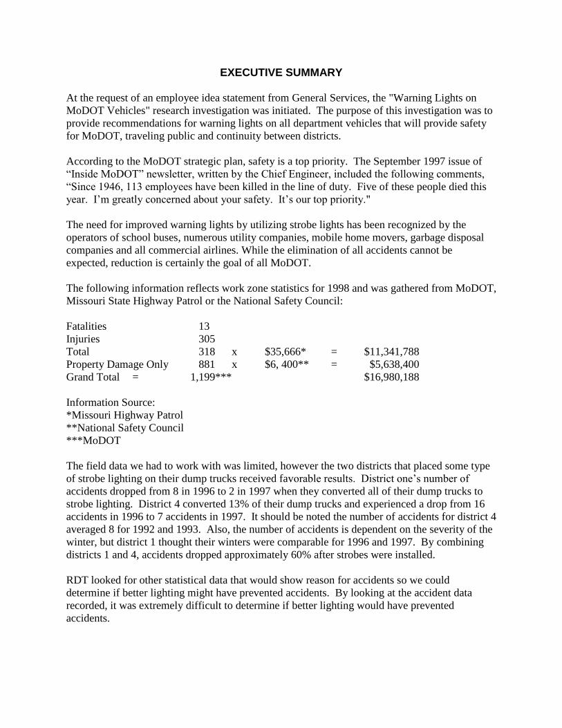
EXECUTIVE SUMMARY
At the request of an employee idea statement from General Services, the "Warning Lights on
MoDOT Vehicles" research investigation was initiated. The purpose of this investigation was to
provide recommendations for warning lights on all department vehicles that will provide safety
for MoDOT, traveling public and continuity between districts.
According to the MoDOT strategic plan, safety is a top priority. The September 1997 issue of
“Inside MoDOT” newsletter, written by the Chief Engineer, included the following comments,
“Since 1946, 113 employees have been killed in the line of duty. Five of these people died this
year. I’m greatly concerned about your safety. It’s our top priority."
The need for improved warning lights by utilizing strobe lights has been recognized by the
operators of school buses, numerous utility companies, mobile home movers, garbage disposal
companies and all commercial airlines. While the elimination of all accidents cannot be
expected, reduction is certainly the goal of all MoDOT.
The following information reflects work zone statistics for 1998 and was gathered from MoDOT,
Missouri State Highway Patrol or the National Safety Council:
Fatalities 13
Injuries 305
Total 318 x $35,666* = $11,341,788
Property Damage Only 881 x $6, 400** = $5,638,400
Grand Total = 1,199*** $16,980,188
Information Source:
*Missouri Highway Patrol
**National Safety Council
***MoDOT
The field data we had to work with was limited, however the two districts that placed some type
of strobe lighting on their dump trucks received favorable results. District one’s number of
accidents dropped from 8 in 1996 to 2 in 1997 when they converted all of their dump trucks to
strobe lighting. District 4 converted 13% of their dump trucks and experienced a drop from 16
accidents in 1996 to 7 accidents in 1997. It should be noted the number of accidents for district 4
averaged 8 for 1992 and 1993. Also, the number of accidents is dependent on the severity of the
winter, but district 1 thought their winters were comparable for 1996 and 1997. By combining
districts 1 and 4, accidents dropped approximately 60% after strobes were installed.
RDT looked for other statistical data that would show reason for accidents so we could
determine if better lighting might have prevented accidents. By looking at the accident data
recorded, it was extremely difficult to determine if better lighting would have prevented
accidents.

The proposed lighting system will cost approximately 3.7 million dollars over the three year
period. If this system reduces accidents in work zones only 20%, 3.4 million dollars would be
saved, each year, which is almost equal to the total cost of the system. Any reduction in work
zone accidents above 20% would represent an overall savings, each year, above the total cost of
the project.
Systems recommended in this report are the consensus recommendations of the 36 member
Warning Light Task Force group held on November 3-4, 1998. This task force was comprised of
all districts and business units that reviewed systems displayed on a parking lot at a distance up
to 600 feet. The Director of Operations took their recommendations and visited districts 4, 5 and
6 for additional input. The Director of Operations finalized the Warning Light Policy after this
review with selected districts and submitted it to the districts as policy on April 2, 1999. Since
then, the Director has retired, but his replacement reviewed and redistributed the same policy on
March 10, 2000.
The specifications detail the power requirements and other features of the systems adopted in the
policy, and were written by the team named by the task force, which included personnel from
districts 1 and 6, and General Services, RDT and Traffic business units.
The basic standard warning lights on MoDOT vehicles have not been upgraded for
approximately 40 years. Considering the cost of possible liability and the number of personal
injury claims, it is recommended that MoDOT Senior Management dedicate up-front money to
retrofit MoDOT vehicles with lighting systems that have proven effective in reducing accidents.
The cost of one fatal accident and the cost to retrofit the entire dump truck fleet in the state with
an adequate system are about the same.
Safety and uniformity can be achieved statewide and the entire MoDOT fleet (as identified in
this report) can be equipped with quality systems over a 3 year period for approximately
$3,700,000 plus miscellaneous support equipment and MoDOT labor for installation. The most
cost-effective method of purchasing would be for monthly deliveries over the three-year period
of initial implementation.
A statement from the ‘Statewide Work Zone Safety Campaign’ launched on TV and radio June
28, 1999 included the following: “Safety is our department’s most important goal,” said
MoDOT Director Henry Hungerbeeler. “Missouri experienced nearly 1200 work-zone accidents
in 1998 with 13 fatalities.” “Anything we can do to improve safety, for motorists or ourselves, is
extremely important.”
TABLE OF CONTENTS
INTRODUCTION......................................................................................................................... 1
OBJECTIVES ............................................................................................................................... 3
PRESENT CONDITIONS ........................................................................................................... 4
TECHNICAL APPROACH ......................................................................................................... 6
RESULTS AND DISCUSSION (EVALUATION) .................................................................... 7
CONCLUSIONS ......................................................................................................................... 13
TASK FORCE RECOMMENDATIONS ................................................................................. 15
NEW DUMP TRUCKS (6 LIGHT REMOTE)...................................................................................... 15
IN SERVICE DUMP TRUCKS (6 LIGHT REMOTE) ........................................................................... 16
MOTOR GRADERS, BACKHOES AND LOADERS (3 LIGHT REMOTE) .............................................. 17
MOTOR GRADERS - HAZARDOUS CONDITIONS (6 LIGHT REMOTE) .............................................. 18
SPECIALTY VEHICLES (8 LIGHT REMOTE) ................................................................................... 19
PICKUP TRUCKS, VANS AND CARRYALLS (4 LIGHT MINIBAR) ..................................................... 20
BACKHOES, TRACTORS AND LOADERS (360 DEG. SELF CONTAINED) .......................................... 21
CARS AND PICKUP TRUCKS (2 LIGHT MINIBAR) .......................................................................... 22
ATTENUATOR TRUCKS (3 LIGHT MINIBAR) ................................................................................. 23
MOWER TRACTORS (MASTER/SLAVE OR 4 LIGHT REMOTE) ......................................................... 24
MOTORIST ASSIST PICKUPS (8 LIGHT LIGHTBAR) ....................................................................... 25
MOTORIST ASSIST PICKUPS (12 LIGHT ARROW) .......................................................................... 26
IMPLEMENTATION PLAN .................................................................................................... 27
FOR POLICY OF 10/04/2000
APPENDIX A,B, AND F - SPECIFICATIONS FOR A FOUR LIGHTHEAD 6 LIGHT
REMOTE STROBE SYSTEM FOR MODOT DUMP TRUCKS AND 12 VOLT SYSTEM
LOADERS ................................................................................................................................. A-1
APPENDIX C - SPECIFICATIONS FOR A FOUR LIGHTHEAD 6 LIGHT REMOTE
STROBE SYSTEM FOR 24 VOLT MODOT MOTOR GRADERS AND LOADERS .... C-1
APPENDIX D - SPECIFICATIONS FOR A FOUR LIGHTHEAD 8 LIGHT REMOTE
STROBE SYSTEM FOR MODOT SPECIALTY VEHICLES ........................................... D-1
APPENDIX E - SPECIFICATION A* MODIFIED FOR A TWO LIGHTHEAD 4 LIGHT
REMOTE STROBE SYSTEM FOR MODOT PICKUPS - VANS – CARRYALLS - SUV'S
..................................................................................................................................................... E-1
APPENDIX F - SPECIFICATION FOR A FOUR LIGHTHEAD 6 LIGHT REMOTE
STROBE SYSTEM FOR 12 VOLT LOADERS ( SEE APPENDIX A,B, AND F) ............. F-1
APPENDIX G - SPECIFICATIONS FOR 360 DEGREE SELF-CONTAINED STROBE
BEACON FOR USE ON TRACTORS, AND BACKHOES WITHOUT CAB'S ............... G-1
APPENDIX H - SPECIFICATIONS FOR A TWO LIGHT MINIBAR FOR MODOT
POOL -CARS, PICKUPS, AND MINIVANS ........................................................................ H-1
APPENDIX I - SPECIFICATIONS FOR A THREE LIGHT MINIBAR FOR MODOT
ATTENUATOR TRUCKS ........................................................................................................ I-1
APPENDIX J - SPECIFICATIONS FOR A MASTER/SLAVE, OR 4 LIGHT REMOTE
STROBE WARNING SYSTEM THAT WILL PROVIDE 360 DEGREE COVERAGE
FOR USE ON MOWER TRACTORS ..................................................................................... J-1
APPENDIX K - SPECIFICATIONS FOR A EIGHT LIGHT STROBE LIGHTBAR FOR
MOTORIST ASSIST PICKUPS ............................................................................................. K-1
APPENDIX L - SPECIFICATIONS FOR A TWELVE LIGHT ARROW FOR MODOT
MOTORIST ASSIST PICKUPS……………………………………………………………..L-1
APPENDIX M - SPECIFICATIONS FOR CABLE HARNESSES: FOR USE ON DUMP
TRUCKS, DISTRIBUTOR TRUCKS, MOTOR GRADERS, LOADERS AND OTHER
CASES WHERE A REMOTE POWER CONTROLLER IS USED .................................. M-1
APPENDIX N - WORK PLAN ................................................................................................ N-1
APPENDIX O - MODOT WARNING LIGHT POLICY ..................................................... O-1
APPENDIX P - TASK FORCE FOR WARNING LIGHTS FOR MODOT FLEET ......... P-1
APPENDIX Q – ACCEPTANCE TEAM MEMBERS ......................................................... Q-1
1
INTRODUCTION
The Missouri Department of Transportation (MoDOT) has always prided itself on providing the best
quality of service to the residents and visitors to The State of Missouri. One of the most essential
components that help produce this quality of service is the high degree of emphasis placed on safety to
both Missouri's motorists and MoDOT employees.
MoDOT has equipped its construction and maintenance vehicles with the same basic type of warning
lights for more than 40 years. When MoDOT first adopted revolving lights, they represented the best
available technology at the time. Today, over 40 years later, technology has grown to provide us with
vastly improved warning light systems that are brighter, more reliable, and therefore safer than their
predecessors.
The two most demanding conditions for warning lights are plowing snow in a strong cross wind when a
large snow cloud is being created, and bright sunny days. While the snowstorm conditions are more
dramatic, they are less in number than the bright sunny days. Light systems that are the most effective on
bright sunny days are the same systems that are most effective in snowstorm conditions. This changes the
focus from dealing with a few days a year to dealing with most work days of the year, as most days have
at least some sunshine during the day.
Major findings from a mid 1980's Minnesota investigation support the conclusion on the two most
demanding conditions for warning lights:
Eighty (80) percent of all snow removal related accidents occurred between 6:00 A.M. and 6:00
P.M. (day light hours.)
Seventy-four (74) percent of all snow removal accidents involved vehicles rear-ending the
snowplow truck.
Fifty-four (54) percent of the snow removal accidents listed the "snow cloud" created by the
snowplowing operation as a contributing factor.
Warning lights were appreciably less effective during daylight hours.
Amber lights were the overall best color choice.
It has not been generally perceived those days having the poorest visibility and the brightest days share
the need for the highest intensity lights, or that the same light would fulfill both needs. In many cases it
was felt we could not get lights that would be effective in bright sunlight.
Another concern in MoDOT has been the recommended lights could be too bright and blind approaching
motorists. However, the highway patrol emergency lights have always been brighter than MoDOT
warning lights and isn't an apprehension for them. Brightness capable of blinding oncoming motorists is a
concern but warning lights are not as bright as vehicle headlights, which oncoming motorists meet almost
constantly at night and, to a lesser extent, during daylight hours. The blinding effect of an “out of focus”
headlight was so minimal that checking the aim of the headlights was removed from state inspection
requirements.
Every year, MoDOT related accidents are becoming more frequent due to increasing motorist population,
increasing speed limits, road rage, and more work zones. For MoDOT, increased accidents leads to more
2
liability, more money spent paying for accidents, and most importantly, more personal injury and
sometimes death to motorists and our employees.
Finally, MoDOT has lost the uniformity between districts by using different types of lighting on the same
pieces of equipment performing the same operation in the field. Districts, knowing the technology has
changed, are searching for a better system than they have used in the past.
We need to do what is in our power to minimize the occurrence of these accidents because of the severe
consequences that are a result. Improving our lighting systems on our construction and maintenance
vehicles is a relatively inexpensive solution to the problem, as it would result in increased visibility of our
vehicles and operations. This well-needed improvement would lead to earlier motorist perception of our
operations, increased motorist alertness, a smaller factor of surprise, and safer conditions for motorists,
pedestrians, and our employees.
Though a statewide warning light system upgrade would require a considerable amount of initiative and
funds, benefits would greatly outweigh the costs of lost lives, liability, and associated costs.

3
OBJECTIVES
The objective of this investigation is to provide warning light systems for MoDOT vehicles that will
protect Missouri motorists, MoDOT employees and provide district continuity.
The scope of this investigation is to recommend, assist in the bidding and evaluation, and assist in the
implementation of these warning light systems.
4
PRESENT CONDITIONS
Work zone activities are becoming increasingly more dangerous as speed limits, traffic volumes and the
number of work zones increase. Therefore, safety of the traveling public and our personnel is of great
concern.
Safety is our top priority according to the MoDOT strategic plan. An article on the front of the September
1997 issue of ‘Inside MoDOT’ newsletter, written by a former Chief Engineer included the following
comment, “Safety is our top priority.”
A statement from the Statewide Work Zone Safety campaign launched on TV and radio on June 28, 1999
included the following statements:
“Safety is our department’s most important goal,” said MoDOT Director Henry Hungerbeeler.
“Missouri experienced nearly 1200 work-zone accidents in 1998 with 13 fatalities.” “Anything
we can do to improve safety for motorists or ourselves is extremely important.”
Comments from highway patrol officers around the state usually include the statement "MoDOT warning
lights just are not bright enough." Patrol officers in district one were very impressed with the way traffic
responded to the strobe lights on snowplow trucks during the 1997 - 1998 snow season. This driver
response must be responsible for the decrease in the number of accidents in both district 1 and district 4
following the installation of strobe lights.
Two problems that need to be solved concerning warning lights are:
1. Lights must be intensive enough to be seen on bright-sunny days and in snow clouds
2. Bring uniformity between districts by using the same lights on the same types of equipment.
This should allow for upgrading vehicles which may encounter hazardous conditions.
Trucks with mounted attenuators, snowplow trucks, traffic’s aerial units and sweepers seem to be some of
the most at risk vehicles in the MoDOT fleet. Vehicles that perform these duties need the most effective
lighting available. Most of the heavy and extra heavy-duty trucks and motor graders fall in this category.
Stationary work zone areas, where pickup trucks and miscellaneous other vehicles are parked and or
working, are also high-risk areas where fatalities occur. In reality, any time a MoDOT vehicle is stopped
or slow moving on or near the roadway or shoulder, they need to be highly visible and putting a higher
priority on one over another is very difficult.
At the present time some business units have funds and are purchasing light systems for new vehicles
going into service. Some of these new systems meet the requirements of the new policy and many do not.
Common practices being made are to buy a new system with inadequate power and physical size to
achieve the long range visibility that would be available for a small extra cost. In these cases the long
range visibility is very little, if any better, than the present halogen rotating lights now in service.
Therefore, the money spent was for no benefit. In traveling around the country it is common to
see strobe systems that lack the power to provide sufficient long range visibility to justify the expense of
changing from the present systems.

5
In another situation, the work unit had purchased rotating halogen lights that have very good
visibility but the personnel were not aware of the power generating capacity of the vehicle and were not
aware the system they had installed required 64 amps to operate. Our recommended strobe system, which
would have the same 360 degree coverage, would require 18 amps.
MoDOT should expect accidents to be reduced if more effective light systems are used. As for uniformity
between districts, it has been lost because districts are going different directions while searching for light
systems to meet their needs. This trend undoubtedly will continue until this policy is implemented.
6
TECHNICAL APPROACH
Our approach was to gather what data was available from Districts 1 and 4, perform literature searches,
and gather information from other states. We looked at what is available today and we also looked at
other light systems besides strobes. The approach to this study was:
1. May 23, 1997 - Assigned to this investigation.
2. Began literature search, and received copies of warning light investigations from Minnesota,
South Dakota and New York.
3. Performed field checks on July 21, 1997, at Rockport and St. Joe South sheds and talked to
maintenance personnel. Went to the district 1 office to talk to office personnel that drive
snowplows occasionally, to get an idea of what they perceive as problems in snow removal.
4. On September 22, 1997, Larry Meisel of Risk Management, Steve Norman and Dennis Smith
from district maintenance and Ivan Corp and Nelson Cook from RDT went to St. Paul, Minnesota
to look at the fiber optic system on the MnDOT trucks. While fiber optics is promising and very
versatile systems, we believe they need more development before MoDOT invests in them. While
there, we got a look at the 'Whelen DOT 101A' System.
5. On April 7 and 8, 1998, a group representing 8 districts and General Headquarters met at the
conference room at the Material’s Lab to get consensus of what was needed to make our work
areas more safe.
6. The first 3 weeks of May 1998 the R.D.T. conducted Falling Weight Deflectometer tests on I-70
from Blue Springs to Wentzville. Five different sets of strobe light systems that had been given to
MoDOT for testing and evaluation were evaluated. ‘Code 3’ and ‘Whelen’ provided these
systems for the vehicles in our moving traffic control setup.
7. On November 3, 1998 a task force of 36 employees representing all ten districts, and all business
units in the support center met in the Laboratory conference room. The Director of Operations
charged us to adopt recommendations that were acceptable to all segments of MoDOT. The
preliminary recommendations that had been developed from the April task force meeting were
reviewed and revised.
8. Research, Development and Technology reviewed MoDOT accident data to help determine what
accidents enhanced lighting may have prevented. Actual cost data is not available and sorting by
pavement or driving conditions was not possible at that time. Efforts to determine what accidents
enhanced lighting may prevent, on a statewide scale, were not productive and the data was of little
value.
Data from districts 1 and 4 did have the needed driving condition information and included data from
before and after the use of strobe lights. This data provided the best information available.
7
RESULTS AND DISCUSSION (EVALUATION)
After the ‘Warning Lights on MoDOT Vehicles’ investigation was assigned on May 23, 1997, an
extensive literature search was initiated to find what other states were doing and what new technology
was available. Reports on other states activities were received and reviewed. It seems each state has
unique thoughts on what the problems are and just how to deal with these problems.
On July 21, 1997, a trip was made to the Rockport, and St. Joseph South maintenance sheds. After
discussing the situations maintenance personnel felt were important, District 1 office personnel that drive
snowplows were interviewed to get an idea of what they perceive as problems in snow removal.
On September 22, 1997, Larry Meisel of Risk Management, Steve Norman and Dennis Smith from
district Maintenance and Ivan Corp and Nelson Cook from Research, Development and Technology
(RDT) went to St. Paul, Minnesota to look at fiber optic systems on the MnDOT trucks. While fiber
optics is promising and very versatile systems, we believe they need more development before MoDOT
invests in them. While there, we got a look at the ‘Whelen DOT 101A’ strobe systems that were the
standard on the MnDOT truck fleet. Following the Minnesota trip, preliminary recommendations were
prepared for appraisal. These recommendations included strobe and halogen systems.
On April 7 & 8, 1998, personnel from eight districts, several General Headquarters’ Business Units
including the Chief Council Office, and the Missouri Highway Patrol, responded to an invitation to attend
a review team conference. This team formed the following consensus:
Strobe lights are more likely to gain the attention of the traveling public than other types of lights.
MoDOT must upgrade the vehicle warning lights.
Selecting warning lights to meet the needs of the location is more important than ensuring that
every vehicle is equally equipped in all ten districts.
When minimum standards are set, that minimum standard may need to be enhanced, or added to,
in high traffic and metro areas.
Districts should be allocated money to be used for upgrading warning lights to meet minimum
standards. They also should be provided additional funds for lighting in high traffic and urban
areas.
Individual views of Business Units or District management on specific lights should not delay
upgrading warning lights on MoDOT vehicles.
Decisions on uniform standard systems should be provided by MoDOT Senior Management.
The 1.9 million dollar cost for a fatality accident, reported in the High Accident Location manual,
would pay for equipping the entire MoDOT dump truck fleet.
Advantages of strobe systems over other light systems include:
No moving parts
Longer bulb life (no metallic filament, expect 2000 hours or average of 2 to 3 years)
Less sensitive to vibration and corrosion
Less electrical current required (approx. 1/2 or less) per bulb
The above listed advantages should decrease the lighting-related down time after vehicles are
equipped with strobe lights.
8
Retrofitting the following vehicles with strobe systems was recommended:
The entire dump truck fleet
Signal and lighting vehicles
Sweepers
Asphalt distributor trucks
Signing vehicles
Falling Weight Deflectometer
Stripping vehicles
Mower tractors
Motor graders and highloaders
The group felt it is difficult to determine how priorities should be set and which vehicles should not have
the best lights available.
During the first 3 weeks of May 1998, RDT conducted Falling Weight Deflectometer tests on I-70 from
Blue Springs to Wentzville. Five different sets of strobe light systems given to MoDOT for testing and
evaluation were evaluated. ‘Code 3’ and ‘Whelen’ provided these systems for the vehicles in our moving
traffic control setup. A statewide invitation was issued to observe and provide input into the evaluation of
these systems. Three districts responded to this with very useful input:
1. There are significant differences between systems.
2. When first detected, all colors appear white.
3. White lights wash out in bright sunlight quicker than amber.
These findings concur with a Minnesota report, which stated ‘Amber is the color of choice’ and a Texas
report concluded there is a definite “Color Hierarchy”. The order of urgency to respond by color is red,
blue and amber. This suggests that if the average motorist is going to respond quickly, an amber light will
have to be more intense than the ordinary warning light. Intensity has the same hierarchy as color. The
brighter a light is the more importance it implies.
Data on accident reductions was reviewed after strobe installations in two of our districts. Combined data
from districts 1 and 4 show reduced accident rates by approximately 60% from 1996 to 1997. District 4
only has 13% of their dump trucks equipped with strobe systems. District 1 converted 100% of their
dump trucks, motor graders and loaders to strobes. While neither system is equal to the Minnesota
system, results have been dramatic. A 1997 quote from one safety officer stated "Are strobes making a
difference? It may be too early to tell but crashes are becoming more of an exception rather than a given".
9
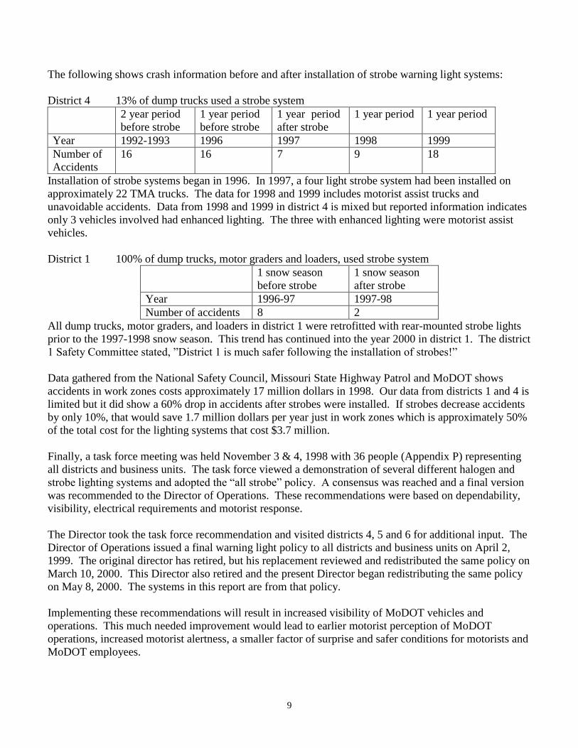
The following shows crash information before and after installation of strobe warning light systems:
District 4 13% of dump trucks used a strobe system
2 year period
before strobe
1 year period
before strobe
1 year period
after strobe
1 year period 1 year period
Year 1992-1993 1996 1997 1998 1999
Number of
Accidents
16 16 7 9 18
Installation of strobe systems began in 1996. In 1997, a four light strobe system had been installed on
approximately 22 TMA trucks. The data for 1998 and 1999 includes motorist assist trucks and
unavoidable accidents. Data from 1998 and 1999 in district 4 is mixed but reported information indicates
only 3 vehicles involved had enhanced lighting. The three with enhanced lighting were motorist assist
vehicles.
District 1 100% of dump trucks, motor graders and loaders, used strobe system
1 snow season
before strobe
1 snow season
after strobe
Year 1996-97 1997-98
Number of accidents 8 2
All dump trucks, motor graders, and loaders in district 1 were retrofitted with rear-mounted strobe lights
prior to the 1997-1998 snow season. This trend has continued into the year 2000 in district 1. The district
1 Safety Committee stated, ”District 1 is much safer following the installation of strobes!”
Data gathered from the National Safety Council, Missouri State Highway Patrol and MoDOT shows
accidents in work zones costs approximately 17 million dollars in 1998. Our data from districts 1 and 4 is
limited but it did show a 60% drop in accidents after strobes were installed. If strobes decrease accidents
by only 10%, that would save 1.7 million dollars per year just in work zones which is approximately 50%
of the total cost for the lighting systems that cost $3.7 million.
Finally, a task force meeting was held November 3 & 4, 1998 with 36 people (Appendix P) representing
all districts and business units. The task force viewed a demonstration of several different halogen and
strobe lighting systems and adopted the “all strobe” policy. A consensus was reached and a final version
was recommended to the Director of Operations. These recommendations were based on dependability,
visibility, electrical requirements and motorist response.
The Director took the task force recommendation and visited districts 4, 5 and 6 for additional input. The
Director of Operations issued a final warning light policy to all districts and business units on April 2,
1999. The original director has retired, but his replacement reviewed and redistributed the same policy on
March 10, 2000. This Director also retired and the present Director began redistributing the same policy
on May 8, 2000. The systems in this report are from that policy.
Implementing these recommendations will result in increased visibility of MoDOT vehicles and
operations. This much needed improvement would lead to earlier motorist perception of MoDOT
operations, increased motorist alertness, a smaller factor of surprise and safer conditions for motorists and
MoDOT employees.
10
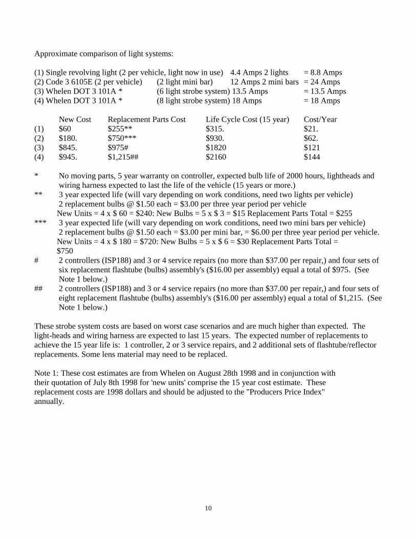
Approximate comparison of light systems:
(1) Single revolving light (2 per vehicle, light now in use) 4.4 Amps 2 lights = 8.8 Amps
(2) Code 3 6105E (2 per vehicle) (2 light mini bar) 12 Amps 2 mini bars = 24 Amps
(3) Whelen DOT 3 101A * (6 light strobe system) 13.5 Amps = 13.5 Amps
(4) Whelen DOT 3 101A * (8 light strobe system) 18 Amps = 18 Amps
New Cost Replacement Parts Cost Life Cycle Cost (15 year) Cost/Year
(1) $60 $255** $315. $21.
(2) $180. $750*** $930. $62.
(3) $845. $975# $1820 $121
(4) $945. $1,215## $2160 $144
* No moving parts, 5 year warranty on controller, expected bulb life of 2000 hours, lightheads and
wiring harness expected to last the life of the vehicle (15 years or more.)
** 3 year expected life (will vary depending on work conditions, need two lights per vehicle)
2 replacement bulbs @ $1.50 each = $3.00 per three year period per vehicle
New Units = 4 x $ 60 = $240: New Bulbs = 5 x $ 3 = $15 Replacement Parts Total = $255
*** 3 year expected life (will vary depending on work conditions, need two mini bars per vehicle)
2 replacement bulbs @ $1.50 each = $3.00 per mini bar, = $6.00 per three year period per vehicle.
New Units = 4 x $ 180 = $720: New Bulbs = 5 x $ 6 = $30 Replacement Parts Total =
$750
# 2 controllers (ISP188) and 3 or 4 service repairs (no more than $37.00 per repair,) and four sets of
six replacement flashtube (bulbs) assembly's ($16.00 per assembly) equal a total of $975. (See
Note 1 below.)
## 2 controllers (ISP188) and 3 or 4 service repairs (no more than $37.00 per repair,) and four sets of
eight replacement flashtube (bulbs) assembly's ($16.00 per assembly) equal a total of $1,215. (See
Note 1 below.)
These strobe system costs are based on worst case scenarios and are much higher than expected. The
light-heads and wiring harness are expected to last 15 years. The expected number of replacements to
achieve the 15 year life is: 1 controller, 2 or 3 service repairs, and 2 additional sets of flashtube/reflector
replacements. Some lens material may need to be replaced.
Note 1: These cost estimates are from Whelen on August 28th 1998 and in conjunction with
their quotation of July 8th 1998 for 'new units' comprise the 15 year cost estimate. These
replacement costs are 1998 dollars and should be adjusted to the "Producers Price Index"
annually.
11
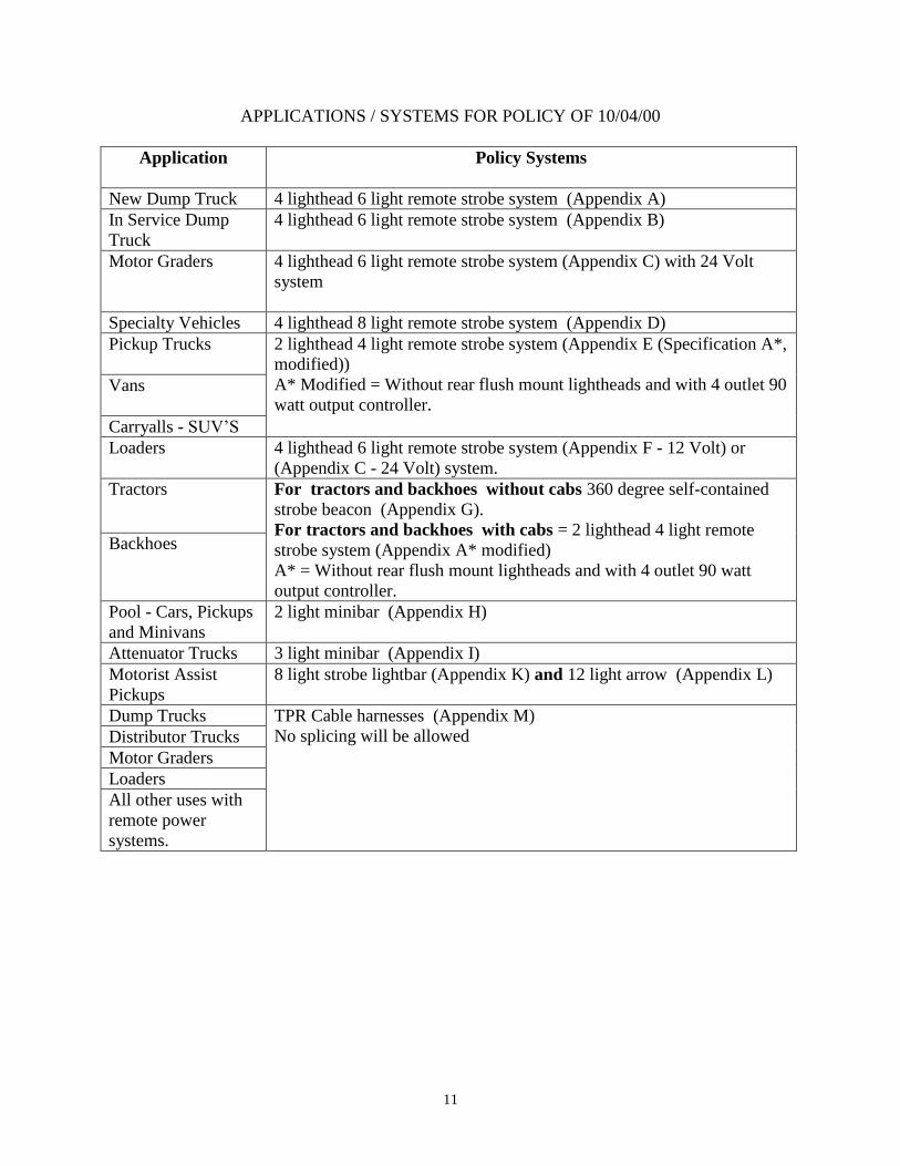
APPLICATIONS / SYSTEMS FOR POLICY OF 10/04/00
Application Policy Systems
New Dump Truck 4 lighthead 6 light remote strobe system (Appendix A)
In Service Dump
Truck
4 lighthead 6 light remote strobe system (Appendix B)
Motor Graders 4 lighthead 6 light remote strobe system (Appendix C) with 24 Volt
system
Specialty Vehicles 4 lighthead 8 light remote strobe system (Appendix D)
Pickup Trucks
2 lighthead 4 light remote strobe system (Appendix E (Specification A*,
modified))
A* Modified = Without rear flush mount lightheads and with 4 outlet 90
watt output controller. Vans
Carryalls - SUV’S
Loaders 4 lighthead 6 light remote strobe system (Appendix F - 12 Volt) or
(Appendix C - 24 Volt) system.
Tractors For tractors and backhoes without cabs 360 degree self-contained
strobe beacon (Appendix G).
For tractors and backhoes with cabs = 2 lighthead 4 light remote
strobe system (Appendix A* modified)
A* = Without rear flush mount lightheads and with 4 outlet 90 watt
output controller.
Backhoes
Pool - Cars, Pickups
and Minivans
2 light minibar (Appendix H)
Attenuator Trucks 3 light minibar (Appendix I)
Motorist Assist
Pickups
8 light strobe lightbar (Appendix K) and 12 light arrow (Appendix L)
Dump Trucks TPR Cable harnesses (Appendix M)
No splicing will be allowed Distributor Trucks
Motor Graders
Loaders
All other uses with
remote power
systems.
12
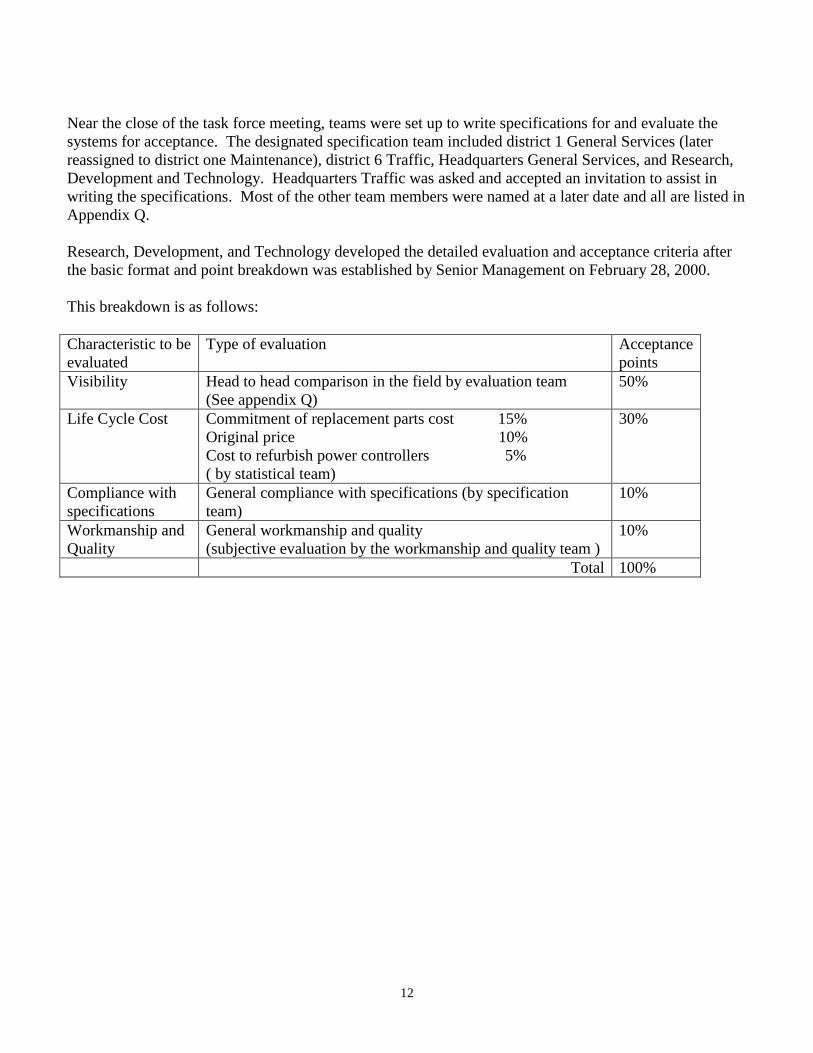
Near the close of the task force meeting, teams were set up to write specifications for and evaluate the
systems for acceptance. The designated specification team included district 1 General Services (later
reassigned to district one Maintenance), district 6 Traffic, Headquarters General Services, and Research,
Development and Technology. Headquarters Traffic was asked and accepted an invitation to assist in
writing the specifications. Most of the other team members were named at a later date and all are listed in
Appendix Q.
Research, Development, and Technology developed the detailed evaluation and acceptance criteria after
the basic format and point breakdown was established by Senior Management on February 28, 2000.
This breakdown is as follows:
Characteristic to be
evaluated
Type of evaluation Acceptance
points
Visibility Head to head comparison in the field by evaluation team
(See appendix Q)
50%
Life Cycle Cost Commitment of replacement parts cost 15%
Original price 10%
Cost to refurbish power controllers 5%
( by statistical team)
30%
Compliance with
specifications
General compliance with specifications (by specification
team)
10%
Workmanship and
Quality
General workmanship and quality
(subjective evaluation by the workmanship and quality team )
10%
Total 100%
13
CONCLUSIONS
From the limited information available it appears an approximate 60% reduction in accidents occurred
after the installation of strobe systems in districts 1 and 4. A similar record would be expected after all
vehicles are equipped with one of the systems in this report, as the other districts include both urban and
rural areas also.
Conclusions of this study include:
Technology has changed over 40 years.
We do not have district continuity.
Fiber optics need more development.
Snow clouds are dangerous.
Bright sunshine days are dangerous.
Warning lights helped reduce accidents involving MoDOT vehicles in District 1 & 4.
The cost of a fatality (average of 1.9 million dollars per fatality) may pay for the light system of all
MoDOT dump trucks.
A 20% reduction of accidents in work zones, in one year, would save approximately the same
amount of money the total lighting system would cost.
Items for present and future consideration include:
Districts may not have the money to implement the recommended upgrades.
The need to upgrade warning light systems may justify the use of off the top, up-front money.
Decisions on standard systems and up front money should be provided by MoDOT Senior
Management so state wide uniformity can be maintained.
Accidents are a real expense factor and while they cannot all be eliminated, money spent avoiding
accidents is better spent than money spent paying for accidents.
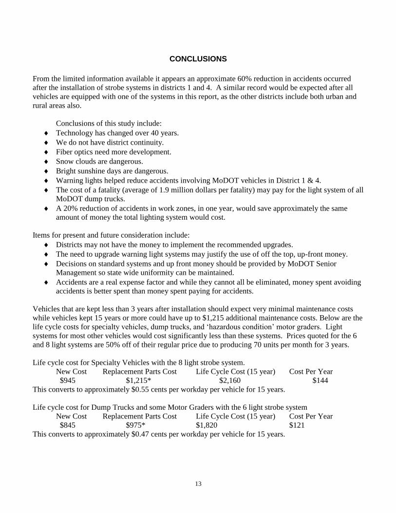
Vehicles that are kept less than 3 years after installation should expect very minimal maintenance costs
while vehicles kept 15 years or more could have up to $1,215 additional maintenance costs. Below are the
life cycle costs for specialty vehicles, dump trucks, and ‘hazardous condition’ motor graders. Light
systems for most other vehicles would cost significantly less than these systems. Prices quoted for the 6
and 8 light systems are 50% off of their regular price due to producing 70 units per month for 3 years.
Life cycle cost for Specialty Vehicles with the 8 light strobe system.
New Cost Replacement Parts Cost Life Cycle Cost (15 year) Cost Per Year
$945 $1,215* $2,160 $144
This converts to approximately $0.55 cents per workday per vehicle for 15 years.
Life cycle cost for Dump Trucks and some Motor Graders with the 6 light strobe system
New Cost Replacement Parts Cost Life Cycle Cost (15 year) Cost Per Year
$845 $975* $1,820 $121
This converts to approximately $0.47 cents per workday per vehicle for 15 years.

14
* These costs are based on worst case scenarios and are much more than expected. Costs are in 1998 dollars , which must be adjusted to the "Producers Price Index"
annually.
15
TASK FORCE RECOMMENDATIONS
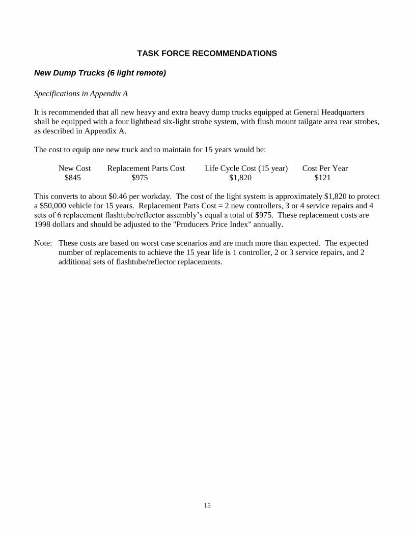
New Dump Trucks (6 light remote)
Specifications in Appendix A
It is recommended that all new heavy and extra heavy dump trucks equipped at General Headquarters
shall be equipped with a four lighthead six-light strobe system, with flush mount tailgate area rear strobes,
as described in Appendix A.
The cost to equip one new truck and to maintain for 15 years would be:
New Cost Replacement Parts Cost Life Cycle Cost (15 year) Cost Per Year
$845 $975 $1,820 $121
This converts to about $0.46 per workday. The cost of the light system is approximately $1,820 to protect
a $50,000 vehicle for 15 years. Replacement Parts Cost = 2 new controllers, 3 or 4 service repairs and 4
sets of 6 replacement flashtube/reflector assembly’s equal a total of $975. These replacement costs are
1998 dollars and should be adjusted to the "Producers Price Index" annually.
Note: These costs are based on worst case scenarios and are much more than expected. The expected
number of replacements to achieve the 15 year life is 1 controller, 2 or 3 service repairs, and 2
additional sets of flashtube/reflector replacements.
16
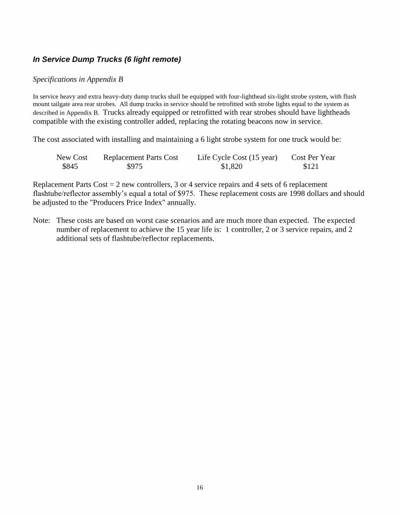
In Service Dump Trucks (6 light remote)
Specifications in Appendix B
In service heavy and extra heavy-duty dump trucks shall be equipped with four-lighthead six-light strobe system, with flush
mount tailgate area rear strobes. All dump trucks in service should be retrofitted with strobe lights equal to the system as
described in Appendix B. Trucks already equipped or retrofitted with rear strobes should have lightheads
compatible with the existing controller added, replacing the rotating beacons now in service.
The cost associated with installing and maintaining a 6 light strobe system for one truck would be:
New Cost Replacement Parts Cost Life Cycle Cost (15 year) Cost Per Year
$845 $975 $1,820 $121
Replacement Parts Cost = 2 new controllers, 3 or 4 service repairs and 4 sets of 6 replacement
flashtube/reflector assembly’s equal a total of $975. These replacement costs are 1998 dollars and should
be adjusted to the "Producers Price Index" annually.
Note: These costs are based on worst case scenarios and are much more than expected. The expected
number of replacement to achieve the 15 year life is: 1 controller, 2 or 3 service repairs, and 2
additional sets of flashtube/reflector replacements.
17
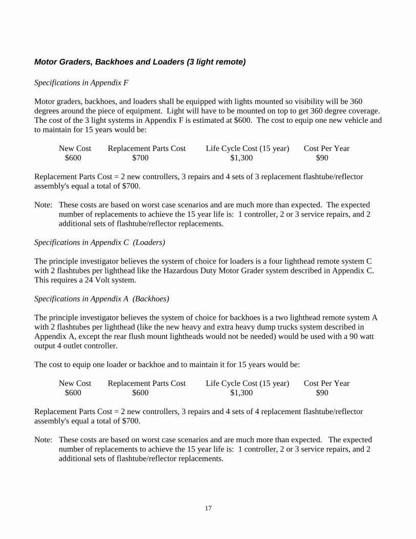
Motor Graders, Backhoes and Loaders (3 light remote)
Specifications in Appendix F
Motor graders, backhoes, and loaders shall be equipped with lights mounted so visibility will be 360
degrees around the piece of equipment. Light will have to be mounted on top to get 360 degree coverage.
The cost of the 3 light systems in Appendix F is estimated at $600. The cost to equip one new vehicle and
to maintain for 15 years would be:
New Cost Replacement Parts Cost Life Cycle Cost (15 year) Cost Per Year
$600 $700 $1,300 $90
Replacement Parts Cost = 2 new controllers, 3 repairs and 4 sets of 3 replacement flashtube/reflector
assembly's equal a total of $700.
Note: These costs are based on worst case scenarios and are much more than expected. The expected
number of replacements to achieve the 15 year life is: 1 controller, 2 or 3 service repairs, and 2
additional sets of flashtube/reflector replacements.
Specifications in Appendix C (Loaders)
The principle investigator believes the system of choice for loaders is a four lighthead remote system C
with 2 flashtubes per lighthead like the Hazardous Duty Motor Grader system described in Appendix C.
This requires a 24 Volt system.
Specifications in Appendix A (Backhoes)
The principle investigator believes the system of choice for backhoes is a two lighthead remote system A
with 2 flashtubes per lighthead (like the new heavy and extra heavy dump trucks system described in
Appendix A, except the rear flush mount lightheads would not be needed) would be used with a 90 watt
output 4 outlet controller.
The cost to equip one loader or backhoe and to maintain it for 15 years would be:
New Cost Replacement Parts Cost Life Cycle Cost (15 year) Cost Per Year
$600 $600 $1,300 $90
Replacement Parts Cost = 2 new controllers, 3 repairs and 4 sets of 4 replacement flashtube/reflector
assembly's equal a total of $700.
Note: These costs are based on worst case scenarios and are much more than expected. The expected
number of replacements to achieve the 15 year life is: 1 controller, 2 or 3 service repairs, and 2
additional sets of flashtube/reflector replacements.

18
Motor Graders - Hazardous Conditions (6 light remote)
Specifications in Appendix C
Motor graders working in hazardous conditions may be allowed to upgrade to the 6 light systems. All
motor grades should be retrofitted with the four lighthead six light remote strobe system described in
Appendix C.
The cost associated with installing the 6 light strobe system for one grader would be:
New Cost Replacement Parts Cost Life Cycle Cost (15 year) Cost Per Year
$845 $975 $1,820 $121
Replacement Parts Cost = 2 new controllers, 3 or 4 service repairs and 4 sets of replacement
flashtube/reflector assembly’s equal a total of $975. These replacement costs are 1998 dollars and should
be adjusted to the "Producers Price Index" annually.
Note: These costs are based on worst case scenarios and are much more than expected. The expected
number of replacement to achieve the 15 year life is: 1 controller, 2 or 3 service repairs, and 2
additional sets of flashtube/reflector replacements.
19
Specialty Vehicles (8 light remote)
Specifications in Appendix D
It is recommended that all specialty units, such as signal, lighting, striping, and other vehicles with special
needs, shall be equipped with have a four lighthead eight light remote strobe system, as described in
Appendix D.
The cost to equip one new vehicle with an 8 light strobe system and to maintain for 15 years would be:
New Cost Replacement Parts Cost Life Cycle Cost (15 year) Cost Per Year
$945 $1,215 $2,160 $144
This converts to about $0.55 per workday. Replacement Parts Costs = 2 new controllers, 3 or 4 service
repairs and 4 sets of 8 replacement flashtube/reflector assembly’s equal a total of $1,215. These
replacement costs are 1998 dollars and should be adjusted to the "Producers Price Index" annually.
Note: These costs are based on worst case scenarios and are much more than expected. The expected
number of replacement to achieve the 15 year life is: 1 controller, 2 or 3 service repairs, and 2
additional sets of flashtube/reflector replacements.
20
Pickup Trucks, Vans and Carryalls (4 light minibar)
Pickups, vans and carryalls shall have one 360 self-contained strobe beacon as described in Appendix G.
However if traffic conditions warrant, the system can be upgraded to one or two 4-strobe linear flashtube
light bars as described in Appendix E. Also a two lighthead remote system with 2 or 3 flashtubes per
lighthead (like the dump truck system described in Appendix A) may be used with a 90 watt output 4
outlet controller. The 2 flashtube lightheads should be used with a 90 watt output 4 outlet controllers.
Specifications in Appendix G
The cost of a beacon system described in Appendix G is estimated at $175. The actual expected life cycle
cost should be no more than $350.
New Cost Replacement Parts Cost Life Cycle Cost (10 year) Cost Per Year
$175 $175 $350 $35
It should be noted the principle investigator believes 2 beacons should be used because some of the
terrain, ditches or in slopes can tilt vehicles to where a single beacon would not be seen.
Specifications in Appendix E
The cost of the two mini bars system described in Appendix E, per vehicle, with a five-year minimum
expected life per mini bar would be:
New Cost Replacement Parts Cost Life Cycle Cost (10 year) Cost Per Year
$800 $800 $1,600 $160
The actual expected life cycle cost should be no more than $1,200. Off road vehicles should have
breakover mounts and /or steel mesh protective guards.
Specifications in Appendix A
A two lighthead remote system with 2 flashtubes per lighthead (like the dump truck system described in
Appendix A) may be used with a 90 watt output 4 outlet controller. The cost to equip one new vehicle
and to maintain for 10 years would be:
New Cost Replacement Parts Cost Life Cycle Cost (10 year) Cost Per Year
$600 $425 $1,025 $100
Replacement Parts Cost = 1 new controller and 1 set of 4 replacement flashtube/reflector assembly’s
equal a total of $425.
21
Backhoes, Tractors and Loaders (360 deg. self contained)
Specifications in Appendix G
Backhoes, tractors, and loaders, shall be equipped with lights mounted so visibility will be 360 around
the piece of equipment, and shall have the option of one or two 360 strobe beacons or four linear flush
mount type strobes, (one facing each direction). If installed on rental tractor and kept 3 years,
replacement cost should be minimal.
The cost of 2 lights in Appendix G is estimated at $350. Lights will need to be shielded on the cab side to
avoid flashes coming in on the operator from both sides
New Cost Replacement Parts Cost Life Cycle Cost (10 year) Cost Per Year
$350 $350 $700 $70
Specifications in Appendix J
The cost of a 4 light remote system in Appendix J is estimated at $400 each and would not have a 90 watt
controller or 5 year warranty. No actual price has been obtained. The cost of master/slave 2 light system,
(2 required), is estimated at $150 each or $300 per vehicle. No actual price has been obtained.
New Cost Replacement Parts Cost Life Cycle Cost (10 year) Cost Per Year
$350 $700 $1,050 $105
Replacement Parts Cost = 2 new systems equal a total of $700.
Specifications in Appendix F
Motor graders, backhoes, and loaders shall be equipped with lights mounted so visibility will be 360
degrees around the piece of equipment. Light will have to be mounted on top to get 360 degree coverage.
The cost of the 3 light systems in Appendix F is estimated at $600. The cost to equip one new vehicle and
to maintain for 15 years would be:
New Cost Replacement Parts Cost Life Cycle Cost (15 year) Cost Per Year
$600 $700 $1,300 $90
Replacement Parts Cost = 2 new controllers, 3 repairs and 4 sets of 3 replacement flashtube/reflector
assembly's equal a total of $700.
Note: These costs are based on worst case scenarios and are much more than expected. The expected
number of replacements to achieve the 15 year life is: 1 controller, 2 or 3 service repairs, and 2
additional sets of flashtube/reflector replacements.
22
Cars and Pickup Trucks (2 light minibar)
Cars, minivans, and pickups normally used as pool vehicles or passenger vehicles may use portable, 2-
linear flashtube strobe units as conditions warrant. Cars assigned to employees shall have one or two,
portable or fixed 2- linear flashtube strobe units in back window and as an option one or two additional
units in front, as described in Appendix H.
The two light minibar systems in Appendix H are estimated at $150 each. The systems are warranted for
2 years.
23
Attenuator Trucks (3 light minibar)
It is recommended all attenuator trucks shall be equipped with a three light minibar, as described in
Appendix I. The lightbar shall be a strobe type. Amber shall be the only color emitted from this unit. All
electronics, including the power supply, shall be contained inside the lightbar.
Systems are estimated at $200 each.
(No actual price has been obtained).
24
Mower Tractors (master/slave or 4 light remote)
It is recommended that mower tractors shall be equipped with a master/slave, or a 4 light remote strobe
warning system that will provide 360-degree coverage, as described in Appendix J.
Specifications in Appendix J
Cost of 4 light remote systems is estimated at $400 each (this would not be with a 90-watt controller). No
actual price has been obtained.
The cost of master/slave 2 light system is estimated at $150 each. (2 required) (No actual price has been
obtained).

25
Motorist Assist Pickups (8 light lightbar)
It is recommended that motorist assist pickups shall be equipped with an eight strobe light strobe lightbar,
as described in Appendix K.
Specifications in Appendix K
Motorist Assist vehicles shall have a strobe 8 light lightbar system with turn signals and forward and rear
work lights.
Systems are estimated at $1,200 each.
26
Motorist Assist Pickups (12 light arrow)
It is recommended that motorist assist pickups shall be equipped with a twelve light arrow, as described in
Appendix L.
Specifications in Appendix L
Motorist Assist vehicles shall have a multi functional arrow 4 feet long with 12 lights, either strobe or
halogen.
Systems are estimated at $800 each.

27
IMPLEMENTATION PLAN
If approved by upper management, a 3 year implementation of 2,578 vehicles will require approximately
70 units per month. In addition to these systems, 3,512 other systems will need to be installed on other
vehicles. Warning lights could be placed on the vehicles at General Headquarters and the 10 districts.
Installation and continuity responsible would belong to General Services. A decision will need to be
made by General Services on how the lights will be mounted on rental tractors. Due to the magnitude of
the task of installing light systems on more than 6,000 pieces of equipment, it seems logical to implement
this project over the 3-year period. The cost should be approximately $100,000 per district per year for
three years. Each Business Unit and District will need to submit quantities of each system needed for
their Business Unit / District. The department may want to place warning lights on the higher risk
equipment first.
A-1
SPECIFICATIONS FOR 10/04/00 POLICY
04-04-01
Appendix A – SPECIFICATION A,B, AND F - FOR A FOUR LIGHTHEAD 6 LIGHT 12 VOLT REMOTE STROBE SYSTEM FOR MoDOT DUMP TRUCKS, AND LOADERS
GENERAL REQUIREMENTS:
All connectors, grommets, and strain relief apparatus as needed for a completed installation shall
be included.
No splicing will be allowed in the wiring harness.
1.0 STROBE POWER SUPPLY:
1.1 The strobe power supply used in this system shall have a maximum input of 230 watts.
The desired power output rating is approximately 180 watts. The strobe power supply
shall operate on 12 volts DC and operate through the range of approximately 10-16V DC
with nominal degradation of performance in either intensity or flash rate. All standard
mounting hardware shall be included. A telephone type jack for a 'lamp on' indicator
panel is desired.
1.2 The strobe power supply shall have RFI suppression circuit(s) to prevent radiated, as well
as conducted, interference problems.
1.3 The power supply(s) should be designed with two independent power circuits that
prevent total system shutdown should one power circuit fail.
1.4 The strobe power supply(s) shall have eight (8) output outlets, each using 3-pin AMP
Mate-N-Lock or equivalent connectors. It shall also have two (2) other 4-pin connectors,
one for input power and the other for outlet switching capability. Systems that
incorporate a "lamp on" indicator panel shall provide a jack.
1.5 The strobe power supply shall produce a burst of four impulses per burst to each
flashtube, at a minimum flash rate of 70 bursts per minute.
1.6 The strobe power supply shall be designed with, built-in, output switching capabilities. A
minimum of three selective switching circuits, two that control two outlet pairs and one
that controls a set of four outlets. These circuits shall be controlled by remote on/off
switches, via external connection. Four pairs of two would be satisfactory if the above
criteria could be met.
A-2
1.7 The strobe power supply shall have two external spade-type fuses mounted near the input
power connector for easy field replacement.
1.8 Strobe power supply(s) shall have a manual High/ Low switch which allows the operator
to reduce the intensity for nighttime operation.
1.9 The strobe power supply shall be completely input reverse polarity and short-to-ground
protected via diode and fuse circuitry combination. Full output short protection, which
will shut down the operating power supply circuitry and not damage the power supply or
strobe lamps in any manner, is required.
2.0 CAB COVER (TOP) LIGHTHEAD ASSEMBLIES:
2.1 To be mounted on the cab cover of the dump bed shall be two lightheads, one on each
side of the vehicle. Each lighthead assembly must contain a minimum of two strobe
modules, the xenon flash tube should be permanently affixed to the reflector. One strobe
module shall face diagonally to the front, and the other shall face diagonally to the rear.
These shall be placed in a outward < position and each pair will provide 270 degrees
coverage. When one lighthead is placed on the driver side and one on the passenger side
of the vehicle in a diamond (<>) configuration the combination of the two will provide
360 degrees coverage for the vehicle. Additional flashtube per lighthead is not a
disqualification but is not desired.
2.2 With the use of a 8 outlet power supply with selective output switching capabilities, the
lighthead assembly shall allow for front flashtubes operation, rear flashtubes operation, or
both front and rear flashtubes operation. The two front flashtubes may flash
simultaneously, and the two rear flashtubes may flash simultaneously or they may flash
alternately. These circuits shall be controlled by manual on/off switches.
2.3 The dimensions of each lighthead should be as small as practical to allow for minimum
of approximately 6-inch linear flashtube modules and for the lens of each flashtube to
have a minimum of approximately 21 square inches.
2.4 All lenses shall be amber in color and have a smooth outer surface.
Driver Side Passenger Side
A-3
2.5 The lighthead assemblies shall be provided with permanent mounting capabilities.
3.0 REAR LIGHTHEAD ASSEMBLIES:
3.1 To be mounted into the rear of the dump beds shall be two strobe flushmount lightheads.
Each lighthead shall be capable of emitting a full 180 of light in the vertical plane while
being recessed into the rear of the dump bed or other similar location.
3.2 The two rear lightheads shall utilize the same power supply unit(s) as the top lighthead
assemblies.
3.3 The lighthead modules shall be easily replaceable. A waterproof connector for each
module shall be used to connect to the cable harness.
3.4 The lighthead lenses shall be made of polycarbonate, amber in color, and have a smooth
outer surface.
3.5 The rear mounted lighthead assemblies shall be suitable for mounting in the steel boxes
attached to the sides, or inside the rear structure of the dump bed. All grommet's, strain
relief items, and connectors will be included in the bid. The lens size shall be a minimum
of approximately 21 sq. inches(7"x3").
4.0 SWITCH CONTROL CENTER:
4.1 A 5-position switch bracket assembly shall provide for permanent mounting.
4.2 Provided shall be one High/Low toggle switch, and three heavy-duty rocker style,
aircraft-type on/off switches. The 5th position shall be open for the 'light on' indicator
panel if provided with the system. All switches shall be prewired with 6-inch pigtail
wires.
5.0 WIRING:
5.1 The heavy-duty TPR foil jacketed cable shall maintain its electrical, mechanical, and
environmental integrity for the life of the vehicle on which it is originally installed. In
addition, it shall be of a quality that will comply with the following parameters: (Note:
No substitutions will be accepted for TPR wire and no splicing will be allowed.)
5.2 Be flexible in cold weather, to minus forty degrees Fahrenheit (-40) and tolerant of hot
temperatures to 194 Fahrenheit.
5.3 Outside TPR insulation jacket shall be highly resistant to abrasion, corrosion, oil/grease,
and normal highway chemicals or environmental abuse for the normal life
expectancy of the vehicle. The minimum TPR thickness shall be approximately:
A-4
3 Conductor = .070 inch.
6 Conductor = .080 inch.
5.4 Each cable shall be foil jacket shielded and have a minimum sixteen (16) gauge, 16 full
tin coated stranded uninsulated pure copper wire.
5.5 Each power conductor shall be a minimum fourteen (14) gauge with 41 pure copper fully
tin coated strands with a minimum .032" TPR insulation.
5.6 The cable will be supplied without fillers.
6.0 WARRANTY:
6.1 The strobe power supply shall be identified by serial number and warranted to MoDOT
directly, to be free of defects of material and/or workmanship for a period of five (5)
years from the date of delivery. The flashtube modules in the cab cover lighthead
assemblies shall be warranted for a period of twenty-four (24) months. The rear module
assemblies shall be warranted for a period of twelve (12) months. Written proof of this
warranty must be provided with bid.
C-1
07-23-01
Appendix C – SPECIFICATIONS FOR A FOUR LIGHTHEAD 6 LIGHT 24 VOLT REMOTE STROBE SYSTEM FOR MoDOT MOTORGRADERS, AND SOME LOADERS
GENERAL REQUIREMENTS:
All connectors, grommets, and strain relief apparatus as needed for a completed installation shall
be included.
No splicing will be allowed in the wiring harness.
1.0 STROBE POWER SUPPLY:
1.1 The strobe power supply used in this system should have a output rating, of a minimum
of 180 watts. The strobe power supply shall operate on 24 volts DC and operate through
the range of 20-28 VDC with nominal degradation of performance in either intensity or
flash rate. All standard mounting hardware shall be included. A telephone type jack for a
'lamp on' indicator panel is desired.
1.2 The strobe power supply shall have RFI suppression circuit(s) to prevent radiated, as well
as conducted, interference problems.
1.3 The power supply(s) should be designed with two independent power circuits that
prevent total system shutdown should one power circuit fail.
1.4 The strobe power supply(s) shall have eight (8) output outlets, each using 3-pin AMP
Mate-N-Lock or equivalent connectors. It shall also have two (2) other 4-pin connectors,
one for input power and the other for outlet switching capability. Systems that
incorporate a "lamp on" indicator panel shall provide a jack.
1.5 The strobe power supply shall produce a burst of four impulses per burst to each
flashtube, at a minimum flash rate of 70 bursts per minute.
1.6 The strobe power supply shall be designed with, built-in, output switching capabilities. A
minimum of three selective switching circuits, two that control two outlet pairs and one
that controls a set of four outlets. These circuits shall be controlled by remote on/off
switches, via external connection. Four pairs of two would be satisfactory if the above
criteria could be met.
1.7 The strobe power supply shall have two external spade-type fuses mounted near the input
power connector for easy field replacement.
C-2
1.8 Strobe power supply(s) shall have a manual High/ Low switch which allows the operator
to reduce the intensity for night time operation.
1.9 The strobe power supply shall be completely input reverse polarity and short-to-ground
protected via diode and fuse circuitry combination. Full output short protection, which
will shut down the operating power supply circuitry and not damage the power supply or
strobe lamps in any manner, is required.
2.0 TOP LIGHTHEAD ASSEMBLIES:
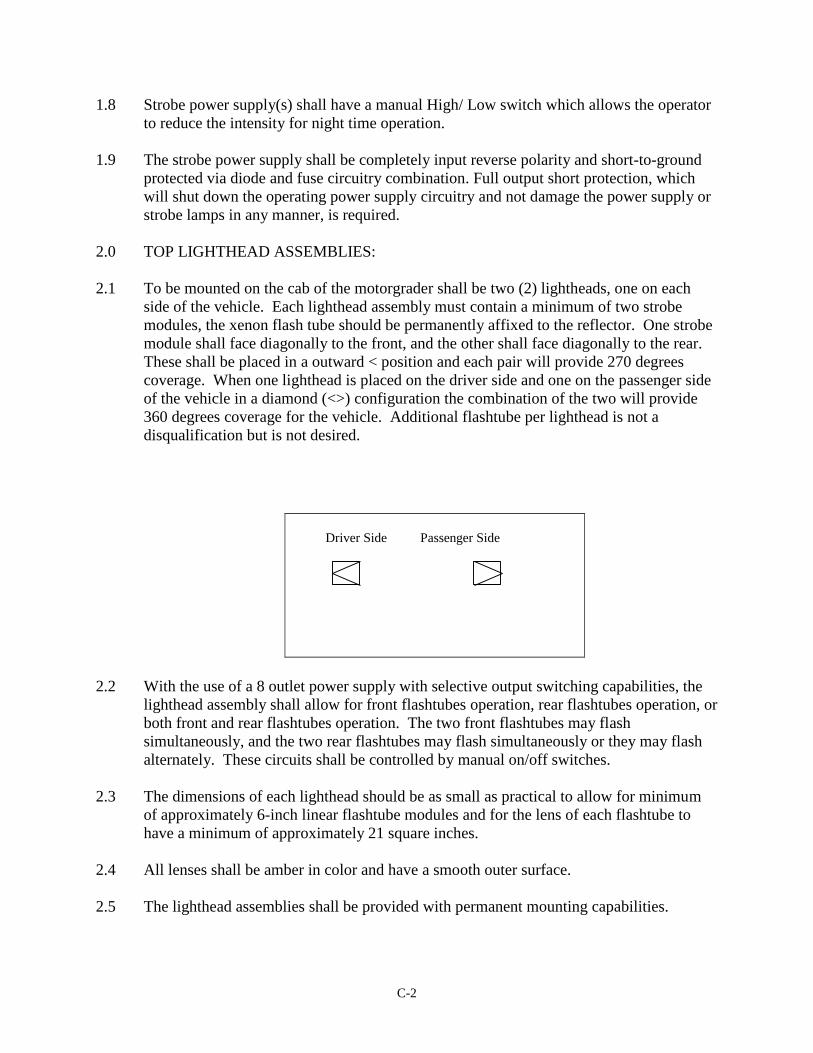
2.1 To be mounted on the cab of the motorgrader shall be two (2) lightheads, one on each
side of the vehicle. Each lighthead assembly must contain a minimum of two strobe
modules, the xenon flash tube should be permanently affixed to the reflector. One strobe
module shall face diagonally to the front, and the other shall face diagonally to the rear.
These shall be placed in a outward < position and each pair will provide 270 degrees
coverage. When one lighthead is placed on the driver side and one on the passenger side
of the vehicle in a diamond (<>) configuration the combination of the two will provide
360 degrees coverage for the vehicle. Additional flashtube per lighthead is not a
disqualification but is not desired.
2.2 With the use of a 8 outlet power supply with selective output switching capabilities, the
lighthead assembly shall allow for front flashtubes operation, rear flashtubes operation, or
both front and rear flashtubes operation. The two front flashtubes may flash
simultaneously, and the two rear flashtubes may flash simultaneously or they may flash
alternately. These circuits shall be controlled by manual on/off switches.
2.3 The dimensions of each lighthead should be as small as practical to allow for minimum
of approximately 6-inch linear flashtube modules and for the lens of each flashtube to
have a minimum of approximately 21 square inches.
2.4 All lenses shall be amber in color and have a smooth outer surface.
2.5 The lighthead assemblies shall be provided with permanent mounting capabilities.
Driver Side Passenger Side
C-3
3.0 REAR LIGHTHEAD ASSEMBLIES:
3.1 The two rear lightheads shall utilize the same power supply unit(s) as the top lighthead
assemblies.
3.2 The lighthead modules shall be easily replaceable. A waterproof connector for each
module shall be used to connect to the cable harness.
3.3 The lighthead lenses shall be made of polycarbonate, amber in color, and have a smooth
outer surface.
3.4 The rear mounted lighthead assemblies shall be suitable for mounting in steel boxes
attached to the rear of the motorgrader. All grommet's, strain relief items, and connectors
will be included in the bid. The lens size shall be a minimum of approximately 21 sq.
inches (7"x3").
4.0 SWITCH CONTROL CENTER:
4.1 A 5-position switch bracket assembly shall provide for permanent mounting.
4.2 Provided shall be one High/Low toggle switch, and three heavy-duty rocker style,
aircraft-type on/off switches. The 5th position shall be open for the 'light on' indicator
panel if provided with the system. All switches shall be prewired with 6-inch pigtail
wires.
5.0 WIRING:
5.1 The heavy-duty TPR foil jacketed cable shall maintain its electrical, mechanical, and
environmental integrity for the life of the vehicle on which it is originally installed. In
addition, it shall be of a quality that will comply with the following parameters: (Note:
No substitutions will be accepted for TPR wire and no splicing will be allowed.)
5.2 Be flexible in cold weather, to minus forty degrees Fahrenheit (-
5.3 Outside TPR insulation jacket shall be highly resistant to abrasion, corrosion, oil/grease,
and normal highway chemicals or environmental abuse for the normal life
expectancy of the vehicle. The minimum TPR thickness shall be approximately:
3 Conductor = .070 inch.
6 Conductor = .080 inch.
5.4 Each cable shall be foil jacket shielded and have a minimum sixteen (16) gauge, 16 full
tin coated stranded uninsulated pure copper wire.
C-4
5.5 Each power conductor shall be a minimum fourteen (14) gauge with 41 pure copper fully
tin coated strands with a minimum .032" TPR insulation.
5.6 The cable will be supplied without fillers.
6.0 WARRANTY:
6.1 The strobe power supply shall be identified by serial number and warranted to MoDOT
directly, to be free of defects of material and/or workmanship for a period of five (5)
years from the date of delivery. The flashtube modules in the cab cover lighthead
assemblies shall be warranted for a period of twenty-four (24) months. The rear module
assemblies shall be warranted for a period of twelve (12) months. Written proof of this
warranty must be provided with bid.
D-1
07-23-01
Appendix D – SPECIFICATIONS – D - FOR A FOUR LIGHTHEAD 8 LIGHT REMOTE STROBE SYSTEM FOR MoDOT SPECIALTY VEHICLES
GENERAL REQUIREMENTS:
All bids shall include connectors, grommets, and strain relief apparatus as needed for a
completed installation.
1.0 STROBE POWER SUPPLY:
1.1 The strobe power supply used in this system shall have a maximum input of 230 watts.
The desired power output rating, is approximately 180 watts. The strobe power supply
shall operate on 12 volts DC and operate through the range of approximately 10-16V DC
with nominal degradation of performance in either intensity or flash rate. All standard
mounting hardware shall be included. A telephone type jack for a 'lamp on' indicator
panel is desired.
1.2 The strobe power supply shall have RFI suppression circuit(s) to prevent radiated, as well
as conducted, interference problems.
1.3 The power supply(s) should be designed with two independent power circuits that
prevent total system shutdown should one power circuit fail.
1.4 The strobe power supply(s) shall have eight (8) output outlets, each using 3-pin AMP
Mate-N-Lock or equivalent connectors. It shall also have two (2) other 4-pin connectors,
one for input power and the other for outlet switching capability. Systems that
incorporate a "lamp on" indicator panel shall provide a jack.
1.5 The strobe power supply shall produce a burst of four impulses per burst to each remote
strobe head, at a minimum flash rate of 70 bursts per minute (per outlet).
1.6 The strobe power supply shall be designed with, built-in, output switching capabilities. A
minimum of three selective switching circuits, two that control two outlet pairs and one
that controls a set of four outlets. These circuits shall be controlled by remote on/off
switches, via external connection. Four pairs of two would be satisfactory if the above
criteria could be met.
1.7 The strobe power supply shall have two external spade-type fuses mounted near the input
power connector for easy field replacement.
1.8 Strobe power supplies shall have a manual High/ Low toggle switch which allows the
operator to reduce the intensity for night time operation.
D-2
1.9 The strobe power supply shall be completely input reverse polarity and short-to-ground
protected via diode and fuse circuitry combination. Full output short protection, which
will shut down the operating power supply circuitry and not damage the power supply or
strobe lamps in any manner, is required.
2.0 TOP LIGHTHEAD ASSEMBLIES:
2.1 To be mounted as high and wide on the vehicle as practical shall be two (2) lightheads,
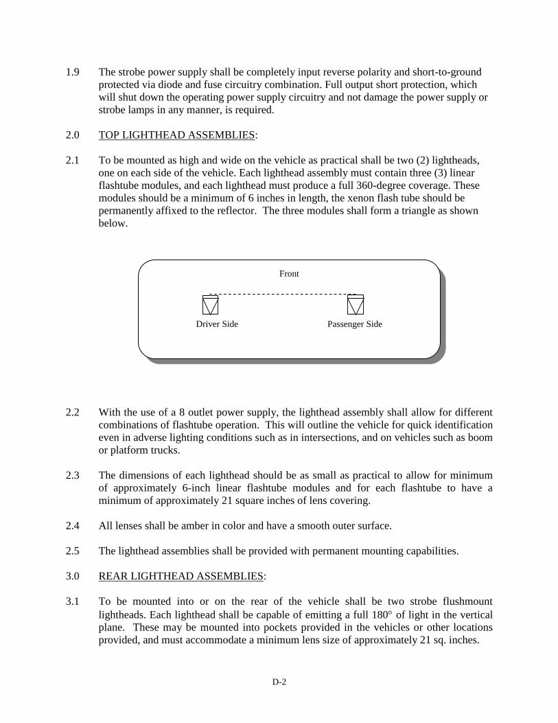
one on each side of the vehicle. Each lighthead assembly must contain three (3) linear
flashtube modules, and each lighthead must produce a full 360-degree coverage. These
modules should be a minimum of 6 inches in length, the xenon flash tube should be
permanently affixed to the reflector. The three modules shall form a triangle as shown
below.
2.2 With the use of a 8 outlet power supply, the lighthead assembly shall allow for different
combinations of flashtube operation. This will outline the vehicle for quick identification
even in adverse lighting conditions such as in intersections, and on vehicles such as boom
or platform trucks.
2.3 The dimensions of each lighthead should be as small as practical to allow for minimum
of approximately 6-inch linear flashtube modules and for each flashtube to have a
minimum of approximately 21 square inches of lens covering.
2.4 All lenses shall be amber in color and have a smooth outer surface.
2.5 The lighthead assemblies shall be provided with permanent mounting capabilities.
3.0 REAR LIGHTHEAD ASSEMBLIES:
3.1 To be mounted into or on the rear of the vehicle shall be two strobe flushmount
lightheads. Each lighthead shall be capable of emitting a full 180 of light in the vertical
plane. These may be mounted into pockets provided in the vehicles or other locations
provided, and must accommodate a minimum lens size of approximately 21 sq. inches.
Front
Driver Side Passenger Side

D-3
Note: Include the price of a 8 gage steel box with appropriate opening for installing the
described lighthead.
3.2 The two rear lightheads shall utilize the same power supply and switching unit as the top
lighthead assemblies.
3.3 The flashtube modules shall be easily replaceable. A waterproof connector for each
module shall be used to connect to the cable harness.
3.4 All grommet's, connectors, and strain relief items will be included in the bid.
3.5 The lighthead lenses shall be made of polycarbonate, amber in color, and have a smooth
outer surface.
4.0 SWITCH CONTROL CENTER:
4.1 A 5-position switch bracket assembly shall provide for permanent mounting.
4.2 Provided shall be one High/Low toggle switch, and three heavy-duty rocker style,
aircraft-type on/off switches. The 5th position shall be open for the 'light on' indicator
panel if provided with the system. All switches shall be prewired with 6-inch pigtail
wires.
5.0 CABLE HARNESSES:
5.1 The heavy-duty TPR foil jacketed cable shall maintain its electrical, mechanical, and
environmental integrity for the life of the vehicle on which it is originally installed. In
addition, it shall be of a quality that will comply with the following parameters: (Note:
No substitutions will be accepted for TPR wire and no splicing will be allowed.)
5.2 Be flexible in cold weather, to minus forty degrees Fahrenheit (-40) and tolerant of hot
temperatures to 194 Fahrenheit.
5.3 Outside TPR insulation jacket shall be highly resistant to abrasion, corrosion, oil/grease,
and normal highway chemicals or environmental abuse for the normal life expectancy of
the vehicle. The minimum TPR thickness shall be approximately:
3 Conductor = .070 inch.
6 Conductor = .080 inch.
9 Conductor = .090 inch.
5.4 Each cable shall be foil jacket shielded and have a minimum sixteen (16) gauge, 16 fully
tin coated stranded noninsulated pure copper wire.
5.5 Each power conductor shall be a minimum fourteen (14) gauge with 41 pure copper fully
tin coated strands with a minimum .032" TPR insulation.
D-4
5.6 The cable will be supplied, without fillers, in multiples of 3 power conductors per cable
(3, 6, and 9 conductor).
5.7 No splicing will be allowed
6.0 WARRANTY:
6.1 The strobe power supply shall be warranted to MoDOT directly, to be free of defects of
material and/or workmanship for a period of five (5) years from the date of delivery. The
flashtube modules in the cab cover lighthead assemblies shall be warranted for a period
of twenty-four (24) months. The rear module assemblies shall be warranted for a period
of twelve (12) months. Written proof of this warranty must be provided with bid.
E-1
07-23-01
Appendix E – SPECIFICATION (A *MODIFIED) SPECIFICATIONS FOR A 2 LIGHTHEAD 4 LIGHT REMOTE STROBE SYSTEM FOR MoDOT PICKUP TRUCKS, VANS, CARRYALLS / SUV’S, AND TRACTORS / BACKHOES WITH CABS
GENERAL REQUIREMENTS:
Shall include connectors, grommets, and strain relief apparatus as needed for a completed
installation.
No splicing will be allowed in the wiring harness.
1.0 STROBE POWER SUPPLY:
1.1 The strobe power supply used in this system shall have a maximum input of 115 watts.
The desired power output rating is approximately 90 watts. The strobe power supply
shall operate on 12 volts DC and operate through the range of approximately 10-16V DC
with nominal degradation of performance in either intensity or flash rate. All standard
mounting hardware shall be included. A telephone type jack for a 'lamp on' indicator
panel is desired.
1.2 The strobe power supply shall have RFI suppression circuit(s) to prevent radiated, as well
as conducted, interference problems.
1.3 The strobe power supply(s) shall have four (4) output outlets, each using 3-pin AMP
Mate-N-Lock or equivalent connectors. It shall also have two (2) other 4-pin connectors,
one for input power and the other for outlet switching capability. Systems that
incorporate a "lamp on" indicator panel shall provide a jack.
1.5 The strobe power supply shall produce a burst of four impulses per burst to each
flashtube, at a minimum flash rate of 70 bursts per minute.
1.6 The strobe power supply shall be designed with, built-in, output switching capabilities. A
minimum of two selective switching circuits, two that control two outlet pairs. These
circuits shall be controlled by remote on/off switches, via external connection.
1.7 The strobe power supply shall have two external spade-type fuses mounted near the input
power connector for easy field replacement.
1.8 Strobe power supply(s) shall have a manual High/ Low switch which allows the operator
to reduce the intensity for nighttime operation.
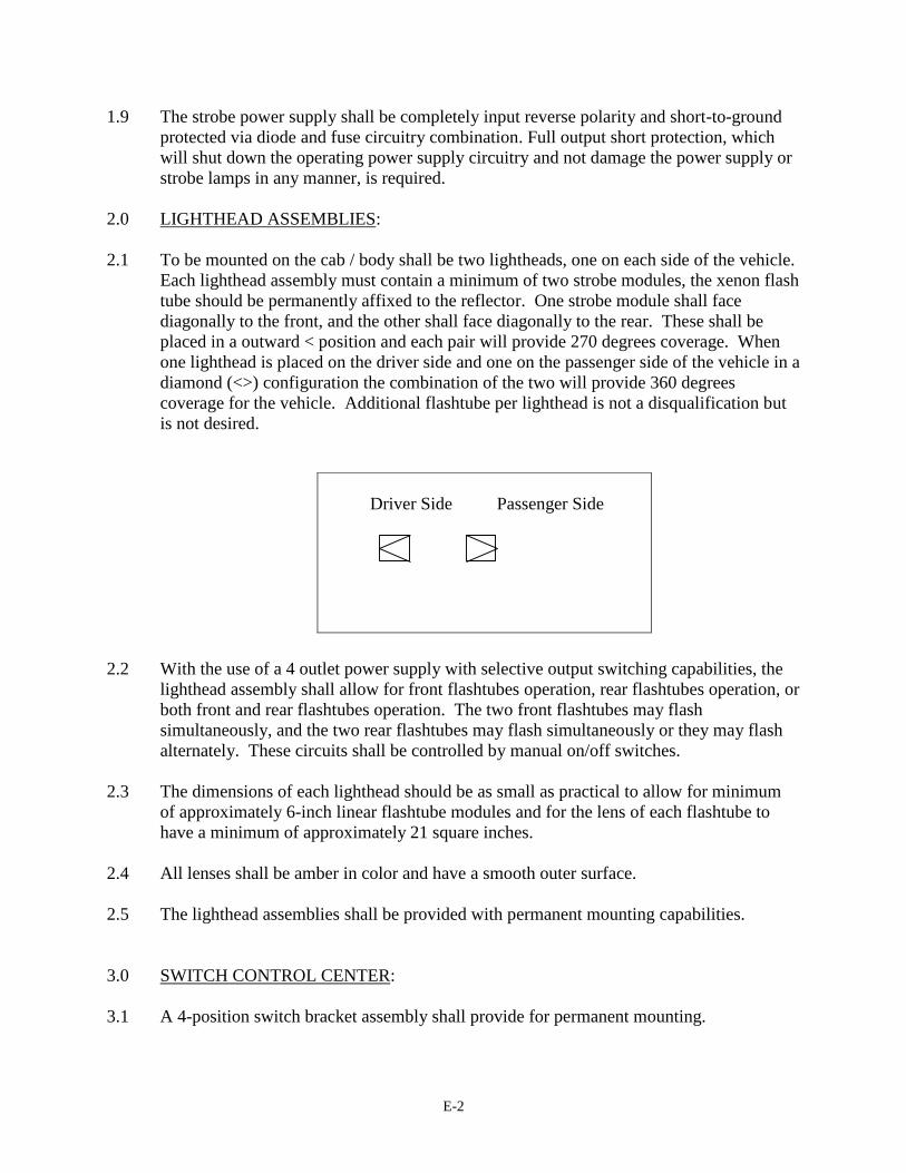
E-2
1.9 The strobe power supply shall be completely input reverse polarity and short-to-ground
protected via diode and fuse circuitry combination. Full output short protection, which
will shut down the operating power supply circuitry and not damage the power supply or
strobe lamps in any manner, is required.
2.0 LIGHTHEAD ASSEMBLIES:
2.1 To be mounted on the cab / body shall be two lightheads, one on each side of the vehicle.
Each lighthead assembly must contain a minimum of two strobe modules, the xenon flash
tube should be permanently affixed to the reflector. One strobe module shall face
diagonally to the front, and the other shall face diagonally to the rear. These shall be
placed in a outward < position and each pair will provide 270 degrees coverage. When
one lighthead is placed on the driver side and one on the passenger side of the vehicle in a
diamond (<>) configuration the combination of the two will provide 360 degrees
coverage for the vehicle. Additional flashtube per lighthead is not a disqualification but
is not desired.
2.2 With the use of a 4 outlet power supply with selective output switching capabilities, the
lighthead assembly shall allow for front flashtubes operation, rear flashtubes operation, or
both front and rear flashtubes operation. The two front flashtubes may flash
simultaneously, and the two rear flashtubes may flash simultaneously or they may flash
alternately. These circuits shall be controlled by manual on/off switches.
2.3 The dimensions of each lighthead should be as small as practical to allow for minimum
of approximately 6-inch linear flashtube modules and for the lens of each flashtube to
have a minimum of approximately 21 square inches.
2.4 All lenses shall be amber in color and have a smooth outer surface.
2.5 The lighthead assemblies shall be provided with permanent mounting capabilities.
3.0 SWITCH CONTROL CENTER:
3.1 A 4-position switch bracket assembly shall provide for permanent mounting.
Driver Side Passenger Side
E-3
3.2 Provided shall be one High/Low toggle switch, and two heavy-duty rocker style, aircraft-
type on/off switches. The 4th position shall be open for the 'light on' indicator panel if
provided with the system. All switches shall be prewired with 6-inch pigtail wires.
4.0 WIRING:
4.1 The heavy-duty TPR foil jacketed cable shall maintain its electrical, mechanical, and
environmental integrity for the life of the vehicle on which it is originally installed. In
addition, it shall be of a quality that will comply with the following parameters: (Note:
No substitutions will be accepted for TPR wire and no splicing will be allowed.)
4.2 Be flexible in cold weather, to minus forty degrees Fahrenheit (-40) and tolerant of hot
temperatures to 194 Fahrenheit.
4.3 Outside TPR insulation jacket shall be highly resistant to abrasion, corrosion, oil/grease,
and normal highway chemicals or environmental abuse for the normal life
expectancy of the vehicle. The minimum TPR thickness shall be approximately:
6 Conductor = .080 inch.
4.4 Each cable shall be foil jacket shielded and have a minimum sixteen (16) gauge, 16 full
tin coated stranded uninsulated pure copper wire.
4.5 Each power conductor shall be a minimum fourteen (14) gauge with 41 pure copper fully
tin coated strands with a minimum .032" TPR insulation.
4.6 The cable will be supplied without fillers.
4.7 No splices will be accepted.
5.0 WARRANTY:
5.1 The strobe power supply shall be identified by serial number and warranted to MoDOT
directly, to be free of defects of material and/or workmanship for a period of five (5)
years from the date of delivery. The flashtube modules in the lighthead assemblies shall
be warranted for a period of twenty-four (24) months.

F-1
Appendix F – SPECIFICATION FOR A FOUR LIGHTHEAD 6 LIGHT REMOTE STROBE SYSTEM FOR 12 VOLT LOADERS ( SEE APPENDIX A,B, AND F)

G-1
07/23/01
Appendix G – SPECIFICATIONS FOR A 360 DEGREE SELF-CONTAINED STROBE BEACON FOR USE ON TRACTORS, AND BACKHOES WITHOUT CABS
The following specifications detail a 360 degree self-contained strobe beacon and shall come
complete with all standard mounting brackets and accessories.
1.0 The lighthead shall be designed with solid-state circuitry, and will incorporate
features to insure a structural and power supply warranty life of 5 years.
1.1 The base, shall contain the power supply, and have both pipe and permanent/flat
mounting provisions.
1.2 The heavy-duty strobe power supply shall have capability of dual voltage, 12 or 24 volts
DC operation, and operate through the range of 10 to 28 volts DC with no degradation of
performance in either intensity.
1.3 The strobe power supply must produce a burst of four impulses per burst at a minimum
flash rate of 70 bursts per minute. A output rating of 30 watts or greater is required.
1.4 The strobe power supply shall have a remote manual High / Off / Low switch which
allows the operator to reduce the intensity for night time operation. The switch must
remain in the High / Off / Low position so the operator can see which mode is selected.
A automatic photocell dimming system is acceptable.
1.5 The strobe light shall have RFI suppression circuits built-in/hard wired within the
electronic assembly to prevent radiated, as well as conducted, interference problems.
1.6 The system shall be completely reverse polarity and short-to-ground protected via diode
and fuse circuitry combination.
1.7 The amber lens shall have a smooth outer surface for self-cleaning purposes. A top and
bottom polished reflector to reflect the light, down and out, and up and out is desired.
2.0 WARRANTY
2.1 The strobe beacon shall be warranted by the manufacturer to the end user directly to be
free from defects of material or workmanship for a period of five (5) years from the date
of delivery. The strobe tube shall be warranted for a period of two (2) years. The strobe
power supply shall be warranted for a period of five (5) years. Written proof of this
warranty by the manufacturer must be furnished by the bidder and attached to this bid.
H-1
07/23/01
Appendix H – SPECIFICATIONS FOR A TWO LIGHT MINIBAR FOR MoDOT POOL - CARS, PICKUPS, AND MINIVANS
GENERAL REQUIREMENTS:
The lightbar shall be a strobe type. All electronics, including the power supply, shall be
contained inside the lightbar.
1.0 BASIC STRUCTURAL DESIGN OF LIGHTBAR:
1.1 Size and weight shall be suitable for mounting on the dash, rear window, or rear deck,
and suitable for mounting on the sun visor is desired.
1.2 Must have linear flashtubes.
1.3 Must provide wide angle visibility
1.4 Must come with power cord long enough to reach from the power point to the rear
window of any full size car. Must come with cigar lighter (power point) adaptor or
remote on off switch. Exact number of each will be supplied with the bid request.
2.0 POWER SUPPLY FOR THE STROBES:
2.1 The strobe lightbar should have a minimum of 20 watt output power supply and shall
operate on 12 volts DC.
2.2 The power supply shall produce a minimum of 60 double flashes, and should produce
70 quad flashes per flashtube per minute with the left and right sides of bar alternately
flashing.
3.0 INTERNAL COMPONENT SYSTEMS:
3.1 Flashtubes and reflectors should be modular in design for ease of replacement.
4.0 WARRANTY:
4.1 The lightbar and all modules shall be warranted by the manufacturer to the user to be free
of defects of material or workmanship for a period of two (2) years from date of delivery.
Flashtube modules shall be warranted for a period of twenty-four (24) months. Written
proof of this warranty by the manufacturer must be furnished by the bidder and attached
to the bid.
I-1
07/23/01
Appendix I – SPECIFICATIONS FOR A THREE LIGHT MINIBAR FOR MoDOT ATTENUATOR TRUCKS
GENERAL REQUIREMENTS:
The lightbar shall be a strobe type. Amber shall be the only color emitted from this unit. All
electronics, including the power supply, shall be contained inside the lightbar.
1.0 BASIC STRUCTURAL DESIGN OF LIGHTBAR:
1.1 The lightbar should be no greater than 24" in length and shall be suitable for
permanent or temporary mounting.
1.2 Must be designed for three flashtubes.
1.3 Must provide wide angle visibility.
1.4 Must have self contained power supply.
1.5 Must have a power cord suitable for a remote on / off power control switch.
2.0 POWER SUPPLY FOR THE STROBES:
2.1 The strobe lightbar shall have a minimum of 60 watt output power supply and shall
operate on 12 volts DC.
2.2 The power supply shall produce a minimum of 60 quad flashes per flashtube per minute.
3.0 INTERNAL COMPONENT SYSTEMS:
3.1 Lamp modules should be modular in design for ease of replacement.
4.0 WARRANTY:
4.1 The lightbar and all modules shall be warranted by the manufacturer to the user to be free
of defects of material and or workmanship for a period of two (2) years from date of
delivery. Written proof of this warranty by the manufacturer must be furnished by the
bidder and attached to the bid.

K-1
07/23/01
Appendix J – SPECIFICATIONS FOR A MASTER/SLAVE, OR 4 LIGHT REMOTE STROBE WARNING SYSTEM THAT WILL PROVIDE 360 DEGREE COVERAGE FOR USE ON TRACTORS AND BACKHOES WITHOUT CABS
Appendix J – AND SPECIFICATIONS HAVE BEEN DELETED
K-2
/23/01
Appendix K – SPECIFICATION FOR A EIGHT STROBE LIGHT LIGHTBAR FOR MOTORIST ASSIST PICKUPS
GENERAL REQUIREMENTS:
The lightbar shall be a strobe type. All electronics, including the power supply, shall be
contained inside the lightbar.
1.0 BASIC STRUCTURAL DESIGN OF LIGHTBAR:
1.1 The lightbar should be a minimum of 58 inches and a maximum of 62 in length, and shall
be supplied for permanent mounting.
1.2 The four (4) end flashtubes shall be placed in a diamond < > configuration which will
give 360 degree visibility for each lightbar. These four flashtubes shall be switched
so the two front facing can be on or off, and the two rear facing can be turned on or
off.
Two additional flashtube shall be facing the front and can be turned on or off. The
remaining two flashtubes, which must face the rear, can be turned on or off
depending on traffic and specific needs.
1.3 The lightbar shall be equipped with brake/turn signal lights facing the rear, and two
(2) clear halogen work lights facing the front and 2 facing the rear.
1.3 The main structural material should be of heavy gauge aluminum.
2.0 POWER SUPPLY FOR THE STROBES:
2.1 The strobe lightbar shall have two power supplies, each shall have a minimum of 90
watts output power, and shall operate on 12 volts DC.
2.2 The power supply shall be able to supply power to four pair of two flashtubes, at the
rate of 70 quad flashes per flashtube per minute.
2.3 The power supply shall have a high/low intensity feature which allows the operator to
reduce the intensity for night time operation. The high/low switching circuit shall utilize
positive voltage to switch the unit into the low intensity mode and must remain in the
High / Off / Low position so the operator can see which intensity is selected.
3.0 INTERNAL COMPONENT SYSTEMS:
3.1 All internal components such as flashtube modules and power supplies shall be
modular in design for ease of replacement without removing the lightbar from the

K-3
vehicle.
4.0 SWITCH CONTROL CENTER:
4.1 A 6-position bracket assembly containing five on/off aircraft-type switches and one High
/ Off / Low switch shall be provided for permanent mounting and shall be permanently
marked for identification purposes. All switches shall be heavy-duty rocker style
switches and prewired to 6 inch pigtail wires.
5.0 WARRANTY:
5.1 The lightbar and all modules shall be warranted by the manufacturer to the user to be
free of defects of material or workmanship for a period of two (2) years from date of
delivery. Flashtube modules shall be warranted for a period of twenty-four (24) `
months. Written proof of this warranty by the manufacturer must be furnished by the
bidder and attached to the bid.
L-1
07/23/01
Appendix L – SPECIFICATIONS FOR A TWELVE LIGHT ARROW FOR MoDOT MOTORIST ASSIST PICKUPS
GENERAL REQUIREMENTS:
The arrow may be a strobe or halogen type.
1.0 BASIC STRUCTURAL DESIGN OF ARROW:
1.1 The arrow shall be approximately 23 inches high and 4 feet in length.
1.2 The arrow shall have side mounting studs
1.3 The arrow housing shall be extruded aluminum
1.4 The light/reflector, and lens shall be rectangular in shape
2.0 POWER SUPPLY FOR THE ARROW:
2.1 The arrow shall operate on 12 volts DC.
2.2 The power supply shall produce a solid flashing arrow to the left, right, or both sides.
3.0 INTERNAL COMPONENT SYSTEMS:
3.1 Strobe units shall have minimum of 270 watts (22.5 watts per flashtube) output.
3.2 Halogen lamps shall be a minimum of 35 watts.
4.0 WARRANTY:
4.1 The arrow board and all modules shall be warranted by the manufacturer to the user
to be free of defects of material or workmanship for a period of two (2) years from
date of delivery. Written proof of this warranty by the manufacturer must be
furnished by the bidder and attached to the bid.
M-1
07/23/01
Appendix M – SPECIFICATIONS FOR CABLE HARNESSES FOR USE ON DUMP TRUCKS, DISTRIBUTOR TRUCKS, MOTORGRADERS, LOADERS, AND ALL OTHER REMOTE POWER USES.
CABLE HARNESSES:
No splicing will be allowed.
The cable shall maintain its electrical, mechanical, and environmental integrity for the
life of the vehicle on which it is originally installed, without the need for re-wiring at any
future time.
The heavy-duty TPR-foil jacketed cable shall be of a quality that will comply with the
following parameters.
A. Be flexible in cold weather, to minus forty degrees Fahrenheit (-40) minimum
and tolerant of hot temperatures to 194 Fahrenheit.
.
B. Outside TPR insulation jacket shall be highly resistant to abrasion, corrosion,
oil/grease, and normal highway chemicals or environmental abuse for the normal
life expectancy of the vehicle. The minimum TPR thickness shall be
approximately:
3 Conductor = .070 inch.
6 Conductor = .080 inch.
9 Conductor = .090 inch.
C. Each cable shall be foil jacket shielded and have a minimum sixteen (16) gauge,
16 fully tin coated stranded uninsulated pure copper wire.
D. Each power conductor shall be a minimum fourteen (14) gauge with 41 pure
copper fully tin coated strands with a minimum .032" TPR insulation.
E. The cable will be supplied, without fillers, in multiples of 3 power conductors per
cable ( 3, 6, and 9 conductor).
WARRANTY
The heavy-duty TPR-foil jacketed cable shall be warranted by the manufacturer to the
end user directly to be free from defects of material or workmanship for a period of five
(5) years from the date of delivery. Written proof of this warranty by the manufacturer
must be furnished by the bidder and attached to this bid.
N-1
Appendix N – Work Plan
RI97006 WORK PLAN FOR DEPARTMENT WORK VEHICLE SAFETY
June 1997
Introduction:
The goal of this investigation is to provide MoDOT with recommendations for lighting on Department
vehicles, which will be in contact with the traveling public. Construction work zones, right of way
mowing, roadway and bridge surveys, snow removal, bridge washing and sweeping, are some duties
department vehicles will be involved in. Lighting systems must meet industry requirements for
maximum and minimum brightness and comply with uniform state and department codes for color.
Dependability, maintenance requirements, usage flexibility, and cost are among the items for
consideration before any recommendations could be made. Trucks with innovative lighting have been
field tested in Iowa, Minnesota and possibly other states with highly recommended functional results.
Cost-effectiveness would have to be considered and include reliability, maintenance cost, liability risk
reduction, installation costs, and additional productivity.
The scope of this investigation is primarily to evaluate, report, and recommend lighting systems for
MoDOT vehicles. Features that will provide safe, reliable visibility, to the traveling public, and provide
the operators with affective vehicular lighting in adverse conditions will be considered.
Expected Benefits:
Benefits will be improved motorist recognition of department work vehicles, and improved visibility of
the work area for vehicle operators, this should reduce costs of accidents and liability. By reducing
liability, down time, and repair costs, productivity should be improved and the initial cost, of the
improved lighting equipment, should be recovered over the life of the vehicles.
Background & Significance of Work:
Iowa and Minnesota have installed warning light systems utilizing photo optic cables with high intensity
light sources, on a number of trucks. They are now evaluating these systems for overall functional and
cost effectiveness. The preliminary operator assessment was very positive. The strong points from the
operators standpoint was it was trouble free, provided light at eight different locations around the truck,
which allowed the driver to monitor functions without leaving the drivers, seat. The bottom line was the
truck stayed in the field nonstop for 2 days during a major snow fight, with out any lighting problems,
and that was very unusual.
On the basis of these findings, Research, Development & Technology (RDT) has decided to initiate an
in-depth investigation.

N-2
At this time, equipment operators need to be polled for thoughts they believe to be important in regard to
equipment operation the main thrust of the investigation will be directed toward snowplows. By
requesting input from part time operators, regular operators, maintenance supervisors, risk management,
and management personnel we should ascertain the shortcomings of the present light systems and the
needs of future systems.
Action Plan:
1. Determine the lighting needs of MoDOT work vehicles by interviewing department employees,
and observing prototype vehicles from Iowa and or Minnesota.
2. Prepare specifications for a small number of trial vehicles to be placed in service in selected
areas for evaluation by MoDOT personnel
3. Evaluate all aspects of function, cost, and risk reduction for a final recommendation
After completion of this analysis, the results and findings will be collected in the form of a final
recommendation
Staffing:
The anticipated staffing for this project will be a Materials Research Engineer, and a Field Testing
Technician.
Budget: The anticipated costs are as follows:
Materials Research Engineer 3 weeks * $1,200/wk = $ 3,600
Field Testing Technician 16 weeks * $750/wk = $12,000
TOTAL = $15,600
Including Salary Additive $15,600 * 1.676 = $26,000
Lighting Equipment 5 units = $12,000
Travel Expense = $ 2,000
Total = $40,000
Funding:
This investigation will be funded by 910/SPR/1997/45/Y.
N-3
Method of Implementation:
Our final recommendation will be sent to the Procurement Division for future purchases of MoDOT
equipment.
STEPS TO TAKE
DO LITERATURE SEARCH AND CHECK WITH OTHER STATES
CHECK WITH DEPARTMENT PERSONNEL ON IDEAS WITHIN OUR STATE
TO BE UNDER DIRECTION OF DON DAVIDSON AND CONSIST OF:
NELSON COOK
IVAN CORP
I CALLED WISCONSIN 6/4/97 FOR ANY INFO THEY MIGHT HAVE
June 13, 1997 at the Blue Ridge shed in KC I attended Federal Signal Demonstration of the Lighting
system on the Iowa, and Minn., demonstration trucks.
June 25, 1997 talked to Randy at garage vibration and corrosion are major problems he was very
positive
June 25, 1997 talked to signal shop, what happens when stepping motor goes out?
July 7, 1997 talked to Stan Grant (GRANTS) made appt. to meet with Dist. 2 Maintenance at 10:30
Wed. July 23, 1997.
July 7, 1997 called for Leland Smithson at Iowa DOT he is out of town thru July 23, I need to call him
then to discuss the Iowa demo truck.
July 8, 1997 talked to Randy at garage. Maintenance personnel have freedom to try innovative ideas in
directing airflow around snowplow.
July 8, 1997 talked to Matt Cowell in Risk Management. Maintenance personnel have freedom to try
innovative ideas in directing airflow around snowplows. Matt will get me cost of snowplowing related
accidents, also he will discuss this subject with Larry Misel. They may get back with me. I need to
discuss light colors with them.
July 8, 1997 I called, Office of the Legislative Auditor, State of Minnesota, Centennial Office Building,
St. Paul inn. 55155. 612 - 296 - 4708. They will send a copy of "Snow and Ice Control May 1995 A
Best Practice Review". Tom Johnson suggested I do this.
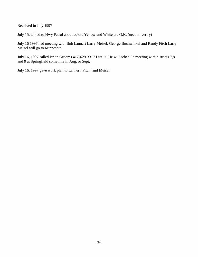
N-4
Received in July 1997
July 15, talked to Hwy Patrol about colors Yellow and White are O.K. (need to verify)
July 16 1997 had meeting with Bob Lannart Larry Meisel, George Bochwinkel and Randy Fitch Larry
Meisel will go to Minnesota.
July 16, 1997 called Brian Grooms 417-629-3317 Dist. 7. He will schedule meeting with districts 7,8
and 9 at Springfield sometime in Aug. or Sept.
July 16, 1997 gave work plan to Lannert, Fitch, and Meisel
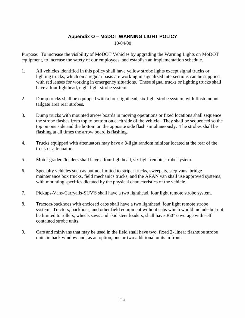
O-1
Appendix O – MoDOT WARNING LIGHT POLICY
10/04/00
Purpose: To increase the visibility of MoDOT Vehicles by upgrading the Warning Lights on MoDOT
equipment, to increase the safety of our employees, and establish an implementation schedule.
1. All vehicles identified in this policy shall have yellow strobe lights except signal trucks or
lighting trucks, which on a regular basis are working in signalized intersections can be supplied
with red lenses for working in emergency situations. These signal trucks or lighting trucks shall
have a four lighthead, eight light strobe system.
2. Dump trucks shall be equipped with a four lighthead, six-light strobe system, with flush mount
tailgate area rear strobes.
3. Dump trucks with mounted arrow boards in moving operations or fixed locations shall sequence
the strobe flashes from top to bottom on each side of the vehicle. They shall be sequenced so the
top on one side and the bottom on the opposite side flash simultaneously. The strobes shall be
flashing at all times the arrow board is flashing.
4. Trucks equipped with attenuators may have a 3-light random minibar located at the rear of the
truck or attenuator.
5. Motor graders/loaders shall have a four lighthead, six light remote strobe system.
6. Specialty vehicles such as but not limited to striper trucks, sweepers, step vans, bridge
maintenance box trucks, field mechanics trucks, and the ARAN van shall use approved systems,
with mounting specifics dictated by the physical characteristics of the vehicle.
7. Pickups-Vans-Carryalls-SUV'S shall have a two lighthead, four light remote strobe system.
8. Tractors/backhoes with enclosed cabs shall have a two lighthead, four light remote strobe
system. Tractors, backhoes, and other field equipment without cabs which would include but not
be limited to rollers, wheels saws and skid steer loaders, shall have 360 coverage with self
contained strobe units.
9. Cars and minivans that may be used in the field shall have two, fixed 2- linear flashtube strobe
units in back window and, as an option, one or two additional units in front.
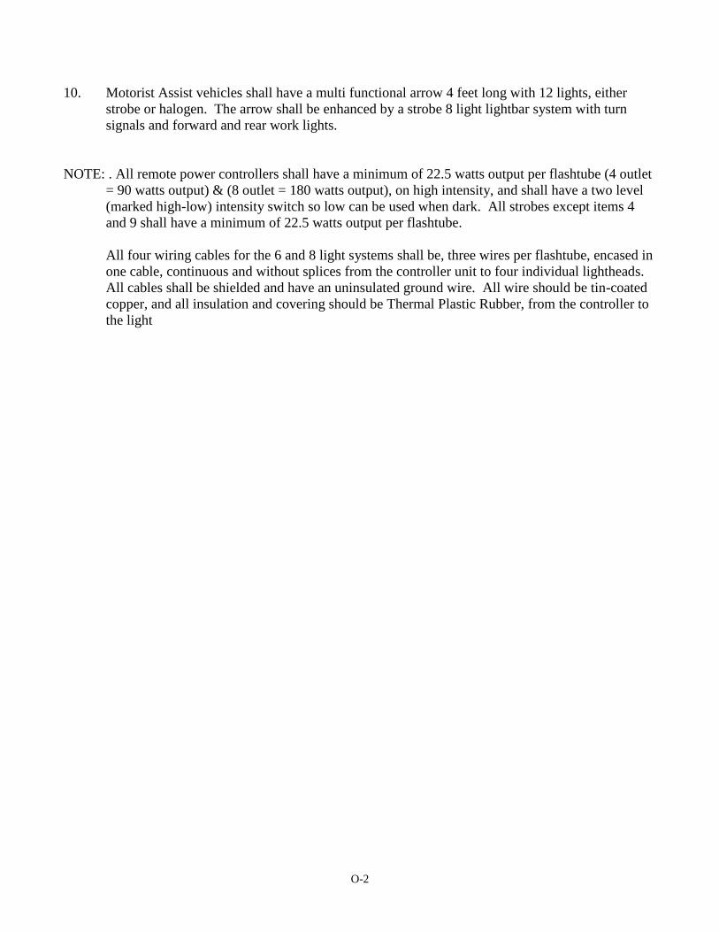
O-2
10. Motorist Assist vehicles shall have a multi functional arrow 4 feet long with 12 lights, either
strobe or halogen. The arrow shall be enhanced by a strobe 8 light lightbar system with turn
signals and forward and rear work lights.
NOTE: . All remote power controllers shall have a minimum of 22.5 watts output per flashtube (4 outlet
= 90 watts output) & (8 outlet = 180 watts output), on high intensity, and shall have a two level
(marked high-low) intensity switch so low can be used when dark. All strobes except items 4
and 9 shall have a minimum of 22.5 watts output per flashtube.
All four wiring cables for the 6 and 8 light systems shall be, three wires per flashtube, encased in
one cable, continuous and without splices from the controller unit to four individual lightheads.
All cables shall be shielded and have an uninsulated ground wire. All wire should be tin-coated
copper, and all insulation and covering should be Thermal Plastic Rubber, from the controller to
the light
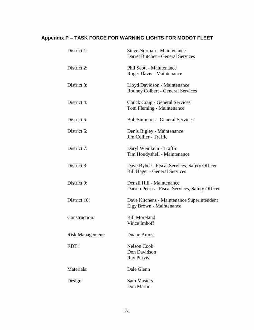
P-1
Appendix P – TASK FORCE FOR WARNING LIGHTS FOR MODOT FLEET
District 1: Steve Norman - Maintenance
Darrel Butcher - General Services
District 2: Phil Scott - Maintenance
Roger Davis - Maintenance
District 3: Lloyd Davidson - Maintenance
Rodney Colbert - General Services
District 4: Chuck Craig - General Services
Tom Fleming - Maintenance
District 5: Bob Simmons - General Services
District 6: Denis Bigley - Maintenance
Jim Collier - Traffic
District 7: Daryl Weinkein - Traffic
Tim Houdyshell - Maintenance
District 8: Dave Bybee - Fiscal Services, Safety Officer
Bill Hager - General Services
District 9: Denzil Hill - Maintenance
Darren Petrus - Fiscal Services, Safety Officer
District 10: Dave Kitchens - Maintenance Superintendent
Elgy Brown - Maintenance
Construction: Bill Moreland
Vince Imhoff
Risk Management: Duane Amos
RDT: Nelson Cook
Don Davidson
Ray Purvis
Materials: Dale Glenn
Design: Sam Masters
Don Martin
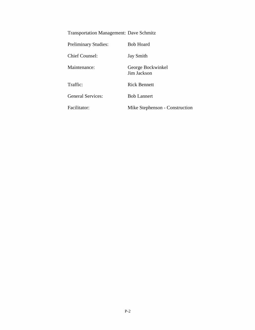
P-2
Transportation Management: Dave Schmitz
Preliminary Studies: Bob Hoard
Chief Counsel: Jay Smith
Maintenance: George Bockwinkel
Jim Jackson
Traffic: Rick Bennett
General Services: Bob Lannert
Facilitator: Mike Stephenson - Construction
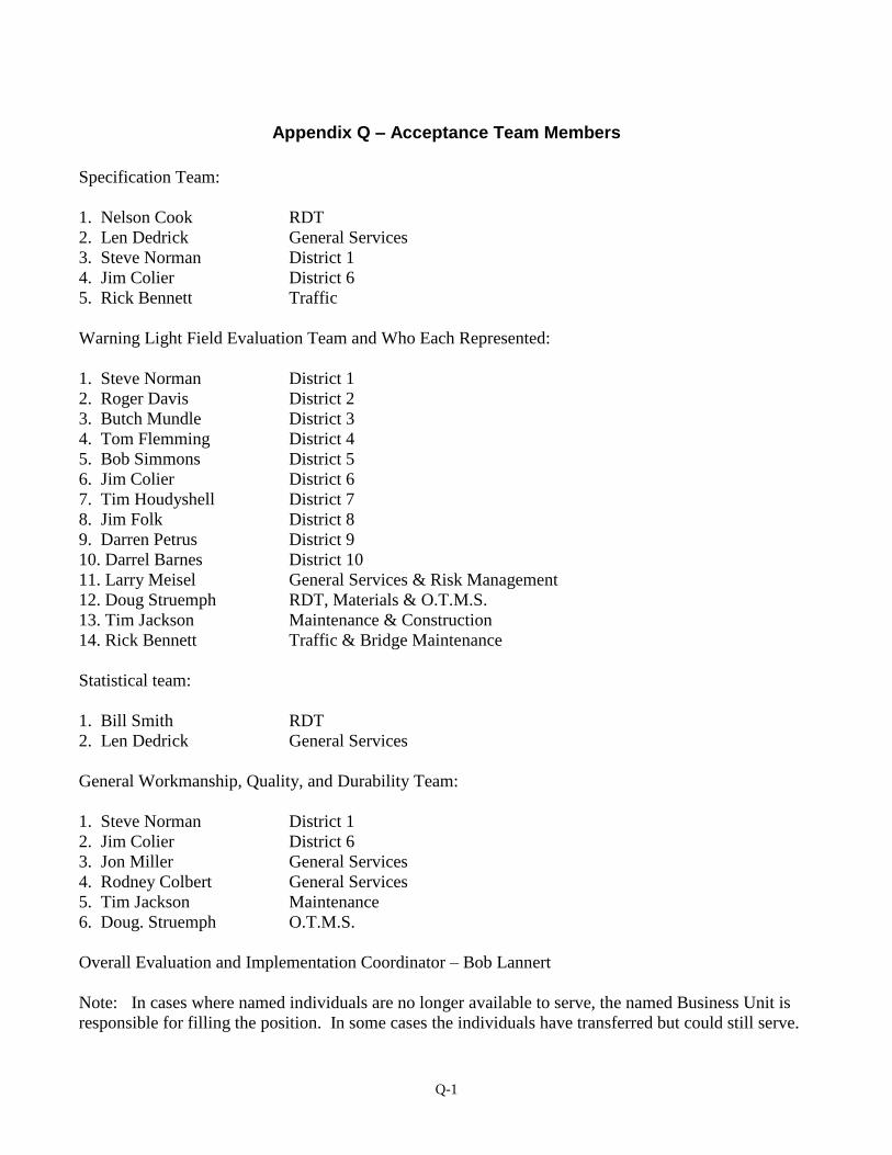
Q-1
Appendix Q – Acceptance Team Members
Specification Team:
1. Nelson Cook RDT
2. Len Dedrick General Services
3. Steve Norman District 1
4. Jim Colier District 6
5. Rick Bennett Traffic
Warning Light Field Evaluation Team and Who Each Represented:
1. Steve Norman District 1
2. Roger Davis District 2
3. Butch Mundle District 3
4. Tom Flemming District 4
5. Bob Simmons District 5
6. Jim Colier District 6
7. Tim Houdyshell District 7
8. Jim Folk District 8
9. Darren Petrus District 9
10. Darrel Barnes District 10
11. Larry Meisel General Services & Risk Management
12. Doug Struemph RDT, Materials & O.T.M.S.
13. Tim Jackson Maintenance & Construction
14. Rick Bennett Traffic & Bridge Maintenance
Statistical team:
1. Bill Smith RDT
2. Len Dedrick General Services
General Workmanship, Quality, and Durability Team:
1. Steve Norman District 1
2. Jim Colier District 6
3. Jon Miller General Services
4. Rodney Colbert General Services
5. Tim Jackson Maintenance
6. Doug. Struemph O.T.M.S.
Overall Evaluation and Implementation Coordinator – Bob Lannert
Note: In cases where named individuals are no longer available to serve, the named Business Unit is
responsible for filling the position. In some cases the individuals have transferred but could still serve.