Embed Size (px)
Citation preview
WANDLService Creation and Provisioning Feature Guide For IP/MPLSView
2 May 2014
Release
6.1.0
Copyright © 2014, Juniper Networks, Inc.

ii
Juniper Networks, Inc.
1194 North Mathilda Avenue
Sunnyvale, California 94089
USA
408-745-2000
www.juniper.net
Juniper Networks, Junos, Steel-Belted Radius, NetScreen, and ScreenOS are registered trademarks of Juniper Networks, Inc. in the United
States and other countries. The Juniper Networks Logo, the Junos logo, and JunosE are trademarks of Juniper Networks, Inc. All other
trademarks, service marks, registered trademarks, or registered service marks are the property of their respective owners.
Juniper Networks assumes no responsibility for any inaccuracies in this document. Juniper Networks reserves the right to change,
modify,transfer, or otherwise revise this publication without notice.
WANDL Service Creation and Provisioning Feature Guide For IP/MPLSView
Copyright © 2014, Juniper Networks, Inc.
All rights reserved.
The information in this document is current as of the date on the title page.
YEAR 2000 NOTICE
Juniper Networks hardware and software products are Year 2000 compliant. Junos OS has no known time-related limitations through the year
2038. However, the NTP application is known to have some difficulty in the year 2036.
END USER LICENSE AGREEMENT
The Juniper Networks product that is the subject of this technical documentation consists of (or is intended for use with) Juniper Networks
software. Use of such software is subject to the terms and conditions of the End User License Agreement (“EULA”) posted at
http://www.juniper.net/support/eula.html. By downloading, installing or using such software, you agree to the terms and conditions of that
EULA.
Copyright © 2014, Juniper Networks, Inc.
About the Documentation
About the Documentation
Documentation and Release Notes
To obtain the most current version of all Juniper Networks® technical documentation, see the product documentation page on the Juniper Networks website at
http://www.juniper.net/techpubs/.
If the information in the latest release notes differs from the information in the documentation,
follow the product Release Notes. Juniper Networks Books publishes books by Juniper Networks
engineers and subject matter experts. These books go beyond the technical documentation to
explore the nuances of network architecture, deployment, and administration. The current list can
be viewed at http://www.juniper.net/books.
Documentation Feedback
We encourage you to provide feedback, comments, and suggestions so that we can improve the documentation. You can provide feedback by using either of the following methods:
Online feedback rating system—On any page at the Juniper Networks Technical Documentation site at http://www.juniper.net/techpubs/index.html, simply click the stars to rate the content, and use the pop-up form to provide us with information about your
experience. Alternately, you can use the online feedback form at
https://www.juniper.net/cgi-bin/docbugreport/.
E-mail—Send your comments to [email protected]. Include the document or topic name, URL or page number, and software version (if applicable).
Requesting Technical Support
Technical product support is available through the Juniper Networks Technical Assistance Center
(JTAC). If you are a customer with an active J-Care or JNASC support contract, or are covered under
warranty, and need post-sales technical support, you can access our tools and resources online or
open a case with JTAC.
JTAC policies—For a complete understanding of our JTAC procedures and policies, review the JTAC User Guide located at
http://www.juniper.net/us/en/local/pdf/resource-guides/7100059-en.pdf.
Product warranties—For product warranty information, visit http://www.juniper.net/support/warranty/.
JTAC hours of operation—The JTAC centers have resources available 24 hours a day, 7
days a week, 365 days a year.
Copyright © 2014, Juniper Networks, Inc. Documentation and Release Notes iii

About the Documentation
Self-Help Online Tools and Resources
For quick and easy problem resolution, Juniper Networks has designed an online self-service portal
called the Customer Support Center (CSC) that provides you with the following features:
Find CSC offerings: http://www.juniper.net/customers/support/
Search for known bugs: http://www2.juniper.net/kb/
Find product documentation: http://www.juniper.net/techpubs/
Find solutions and answer questions using our Knowledge Base: http://kb.juniper.net/
Download the latest versions of software and review release notes: http://www.juniper.net/customers/csc/software/
Search technical bulletins for relevant hardware and software notifications: http://kb.juniper.net/InfoCenter/
Join and participate in the Juniper Networks Community Forum: http://www.juniper.net/company/communities/
Open a case online in the CSC Case Management tool: http://www.juniper.net/cm/
To verify service entitlement by product serial number, use our Serial Number Entitlement (SNE)
Tool: https://tools.juniper.net/SerialNumberEntitlementSearch/
Opening a Case with JTAC
You can open a case with JTAC on the Web or by telephone.
Use the Case Management tool in the CSC at http://www.juniper.net/cm/.
Call 1-888-314-JTAC (1-888-314-5822 toll-free in the USA, Canada, and Mexico). For
international or direct-dial options in countries without toll-free numbers, see
http://www.juniper.net/support/requesting-support.html.
iv Requesting Technical Support Copyright © 2014, Juniper Networks, Inc.

. . . . .
. . . . .
. . . . . . . . . . . . . . . . . . . . . . . . . . . . . . . . . . .Table of Contents
I Introduction I-1Related Documentation I-1Service Creation & Provisioning I-1
Model-Based I-1
Template-Based I-1
Deploying Network Changes I-2Work Order Management I-2
Service Activation and Verification I-2
Getting Started Essentials I-2
1 Document Conventions 1-1Document Conventions 1-1Keyboard, Window, and Mouse Terminology and Functionality 1-1The Keyboard 1-2The Mouse 1-2Information Labels 1-2Changing the Size of a Window 1-2Moving a Window 1-2
2 Model-Based Provisioning 2-1Prerequisites 2-1Related Documentation 2-1Outline 2-1Detailed Procedures 2-1Model-Based Provisioning Orders for Tunnels, VPNs, and VLANs 2-2
Creating a Provisioning Order 2-2
LSP Delta Wizard 2-2LSP Configlets 2-4VPN Configlets 2-5Switch Configlets 2-6VLAN and VPN Windows 2-6Saving Changes 2-6Notes 2-7
3 Provisioning Work Orders 3-1Prerequisites 3-1Related Documentation 3-1Outline 3-1Detailed Procedures 3-1
Copyright © 2014, Juniper Networks, Inc. Contents-1

Activating an Order 3-1Authorizing and Activating an Order 3-3
Recollecting and Verifying the Network 3-5
Rescheduling an order 3-8Appending Configlets 3-8Manually Creating a Provisioning Order 3-8Notification Emails for Provision Work Orders 3-10
4 Customer Service Setup 4-1Prerequisites 4-1Related Documentation 4-1Outline 4-1Terminology 4-1Detailed Procedures 4-2Creating a Customer Service Order Based on Templates 4-2
Physical Topology 4-2
Customer Service, VPN, and Interface Parameters 4-3
Create Customer Service 4-3Setup Customer 4-4Setup Customer Sites 4-4Setup Regions 4-5Setup PE & CE Nodes 4-6
Locking Mechanism 4-7
Setup PE & CE Links 4-8
5 Customer Service Provisioning 5-1Prerequisites 5-1Related Documentation 5-1Outline 5-1Detailed 5-1Create a VPN Customer Service 5-1Defining the Topology 5-3Node Assignment 5-3Port Assignment Step 5-4VPN PE-CE Protocol Selection 5-6Creating a Provisioning Work Order 5-7Activating the Provisioning Work Order 5-9Verification of the New VPN 5-9
6 Customer Service Template Design 6-1Prerequisites 6-1Related Documentation 6-1Outline 6-1Detailed Procedures 6-1Understanding the Customer Service Template Project 6-1
Template Category 6-3
Template Organization 6-3
Creating Customer Service Templates 6-3Creating a Customer Service Template 6-3
Creating an interface template 6-4
Contents-2 Copyright © 2014, Juniper Networks, Inc.
. . . . .
Creating a VPN Template 6-5Understanding Customer Service Templates Syntax 6-5Comments 6-6
Variable Declaration and Definition 6-6
@include Blocks 6-7
Specifying Corresponding Template Types 6-7
Understanding VPN and Interface Templates Syntax 6-7Interface Template 6-7
VPN Template 6-7
Parameters 6-8
Appendix 6-9Usage 6-9
Reserved Variables for Interface Template Type 6-12
Reserved Constants for VPN Template Type 6-15
Reserved Variables with General Scope 6-15
Reserved Variables for Customer Service Template Type 6-15
Reserved Template Variables for Customer Service Template Type 6-16
Reserved Keywords for Customer Service Template 6-17
Reserved Keywords for Non-Customer Service System Templates 6-19
7 Baseline Provisioning 7-1Prerequisites 7-1Related Documentation 7-1Outline 7-1Detailed Procedures 7-1Template-Based Provisioning Orders 7-1
Device Configuration 7-1
8 Baseline Provisioning Template Design 8-1Prerequisites 8-1Related Documentation 8-1Outline 8-1Detailed Procedures 8-1
Designing Device Config Templates 8-1
Creating New Device Config Templates 8-2
Configlet Template Syntax 8-4
Creating a Configlet Group 8-8
Applying a Template 8-9
Template Directory Organization 8-10Appendix - WANDL Reserved Variables 8-10
W_NEIGHBOR_TUNNEL 8-10
W_VPN 8-10
W_TUNNEL 8-10
W_BGP_POLICY 8-11
W_INTF_POLICER 8-11
W_INTF_NAME 8-11
W_INTF_ADDRESS 8-11
W_INTF_ADDRESS_IPV6 8-11
W_NEIGHBOR_IPV6 8-11
Copyright © 2014, Juniper Networks, Inc. Contents-3

W_NEIGHBOR_IP 8-12
W_AS 8-12
W_NODE_ADDRESS 8-12
W_WORK_ORDER 8-12
Contents-4 Copyright © 2014, Juniper Networks, Inc.

. . . . .
. . . . . . . . . . . . . . . . . . . . . . . . . . . . . . . . . . .INTRODUCTION I
P/MPLSView™ is a powerful network engineering and management solution that provides in-depth views of routers, tunnels and connections in an intuitive graphical format.
This IP/MPLSView Service Creation and Provisioning Guide is focused on the provisioning features of the IP/MPLSView software. It explains how to design provisioning templates and how to push CLI and configlets into network devices.
Related Documentat ionFor setup of the live network model, refer to the Management & Monitoring Guide. For details of the traffic engineering features of IP/MPLSView, please refer to the Router Guide and the Design & Planning Guide. For file format details, refer to the File Format Guide.For detailed information about each program window, refer to the General Reference Guide.
Service Creat ion & Provis ioningIP/MPLSView offers several different methods for creating provisioning orders:
M O D E L - B A S E DThese provisioning orders are based on modifications made to the network model, e.g., to LSP tunnels, Layer 3 VPNs, Layer 2 VPNs.
T E M P L A T E - B A S E DThese provisioning orders are based on templates with variables, whose values are specified by the user. For more information on baseline provisioning, refer to Chapter 7, Baseline Provisioning. The Device Templates support Per Vendor, OS, and Version Template Design for repeatable, similar configurations across huge numbers of devices of varying vendor/OS/version that are automatically detected by the system.
There are 4 major categories of templates that are handled in the Template Design window, accessible from Setup > Template Design. These categories are as follows:
• Device config template: These basic provisioning templates allow users to define variables in their templates, whose values will be entered in by the software operator to generate commands, which can then be provisioned on the device. Device config templates are covered in this chapter. For more information on how to create these templates, see Chapter 8, Baseline Provisioning Template Design.
• Service template: These templates are used for service provisioning, and involve multiple templates for one service. For example, this would include a template for the VPN, and a template for the interfaces. Templates can be generated for end-to-end VPNs, e.g., VLAN-VPLS-VLAN. IP/MPLSView supports the creation of service templates (for interfaces, protocols, policies, etc.) from which work orders can be generated. For more information, see Chapter 6, Customer Service Template Design.
• Config management templates: These templates are used for configuration backup and restore, and are unrelated to service creation and provisioning. For more information, see the Management & Monitoring Guide chapter “Configuration Backup and Restore.”
• OS management template: these templates are used for Operating System management, and are unrelated to service creation and provisioning. For more information, see the Management & Monitoring Guide chapter “Configuration Backup and Restore.”
I
Copyright © 2014, Juniper Networks, Inc. I-1

I
Deploying Network Changes
W O R K O R D E R M A N A G E M E N TIP/MPLSView manages Work Order Creation, Tracking, Activation, Verification, History, and Rollback. By coordinating the interactions and complex task dependencies between the various provisioning components, IP/MPLSView also hides network complexity from network operators and simplifies the overall provisioning process.
S E R V I C E A C T I V A T I O N A N D V E R I F I C A T I O NWhen ready, provisioning work orders are activated and configuration changes pushed to the devices, with error reporting, commit, and rollback if necessary. A real-time network update of the live network model enables provisioned changes to be immediately verified against the actual network. Built-in CLI utilities also facilitate the checking of device configurations, routes, etc.
Gett ing Star ted Essent ia lsThe following describes the typical high-level procedures for getting started with the Network Management module, to first set up the network model, and following this, the Service Creation and Provisioning module.
1. Log into IP/MPLSView. When starting up IP/MPLSView, you will be prompted with the welcome screen. Select Manage & Monitor. If this window does not appear, you can also choose File > Open Live Network from the main menu bar.
2. Set up Router Profiles. The next step is to set up router profiles which contain login and password information, allowing you to connect to the devices in your network. You can build a router profile from scratch through the graphical interface, import the information from a text file using the Import Wizard, or populate a router profile automatically using the Autodiscovery or Host Discovery tasks in the Task Manager. These are described further in the Management & Monitoring Guide. Many users choose to perform an Autodiscovery task in the Task Manager to identify the routers that exist in a given network and to automatically populate a router profile. The first step is to select one or more seed routers (e.g. one per area), and specify them in a router profile. The Autodiscovery task will poll the seed routers’ specified router database (e.g. OSPF, ISIS or MPLS database), constructing a list of IP addresses, or routers, that are then polled for their configuration files. Performing an autodiscovery will also automatically populate your router profile with the newly discovered devices. The collected data is automatically parsed by the WANDL software, allowing the network topology to be displayed in the Topology Map at this time.
3. Start the Live Topology Collection. The Scheduling Live Network Collection task in the Task Manager, as described in the Management & Monitoring Guide, if you wish to see near real-time updates of the network status on the Topology Map. Because router configuration files are modified over time, this task is usually scheduled periodically in order to synchronize with the real network. In addition to configuration data, the Live Network Collection also collects interface/tunnel data.
4. Open the Provisioning module.. From the File menu or welcome window, open the provisioning module.
5. Design the provisioning templates.
6. Populate the provisioning templates.
7. Provision the resulting configlets/CLI commands to the device.
I-2 Copyright © 2014, Juniper Networks, Inc.

. . . . .
. . . . . . . . . . . . . . . . . . . . . . . . . . . . . . . . . . .DOCUMENT CONVENTIONS 1
his chapter explains the document conventions used in the IP/MPLSView documentation set delivered with and as part of the IP/MPLSView product.
Document Convent ions• Keyboard keys are represented by bold text appearing in brackets; for example <Enter>.
• Window titles, field names, menu names, menu options, and Graphical User Interface buttons are represented in a bold, sans serif font.• Command line text is indicated by the use of a constant width type.
Keyboard, Window, and Mouse Terminology and Funct ional i tyThe WANDL software documents are written using a specific sort of “vocabulary.” Descriptions of the more important parts of this vocabulary follow.
Note: In the user documentation, mouse button means left mouse button unless otherwise stated.
• Window. Any framed screen that appears on the interface.
• Cursor. The symbol marking the mouse position that appears on the workstation interface. The cursor symbol changes; e.g., in most cases, it is represented as an arrow; in a user-input field, the cursor symbol is represented as a vertical bar.
• Click. Refers to single clicking (pressing and releasing) a mouse button. Used to select (highlight) items in a list, or to press a button in a window.
• Double-click. Refers to two, quick clicks of a mouse button.
• Highlight. The reverse-video appearance of an item when selected (via a mouse click).
• Pop-up menu. The menu displayed when right-clicking in or on a specific area of a window. This menu is not a Main Window window menu. Drag the cursor down along the menu to the menu option you want to select and release the mouse button to make the selection.
• Pull-down menu. The Main Window window menus that are pulled down by clicking and holding down the left mouse button. Drag the cursor down the menu to your selection and release the mouse button to make the selection.
• Radio button. An indented or outdented button that darkens when selected.
• Checkbox. A square box inside of which you click to alternately check or uncheck the box; a checkmark symbol is displayed inside the box when it is “checked.” The checkmark symbol disappears when the box is “unchecked.”
Figure 1-1 Radio button (left) and Checkbox (right)
• Navigation. When you type text into a field, use the <Tab> key or the mouse to move to the next logical field. Click inside a field using the mouse to move directly to that field.
• Grey or Greyed-out. A button or menu selection is described as grey or “greyed-out” when it is available in this release of the WANDL software but currently has been inactivated so that the user cannot use it or select it.
T
Copyright © 2014, Juniper Networks, Inc. 1-1

D O C U M E N T C O N V E N T I O N S1
The KeyboardThe cursor keys located on the lower two rows of this keypad perform cursor movement functions for the window cursor. They are labeled with four directional arrows on the key caps. The WANDL software makes use of these keys for cursor movement within files.
The following keys or key combinations can be used in the WANDL software windows except where noted:
• Click on a file then hold down the <Shift> key while clicking on another file to select the file first clicked on and all files in between.
• Click on a file and then hold down the <Ctrl> key while clicking on another file to select the file first clicked on and the file next clicked on without selecting any of the files in between. You can continue to <Ctrl>-click to select additional, single files.
The MouseThe PC mouse has two buttons; the workstation mouse has three buttons. The WANDL software makes use of the left and right mouse buttons on both the PC and the workstation. The workstation’s middle mouse button is not used.
The following terms describe operations that can be performed with the mouse.
• Point. Position a mouse pointer (cursor) on an object.
• Click. Quickly press and release the left mouse button without moving the mouse pointer.
• Right-click. Quickly press and release the right mouse button without moving the mouse pointer.
• Double-click. Quickly click a mouse button twice in succession without moving the mouse pointer.
• Press. Hold down the mouse button.
• Release. Release a mouse button after it has been pressed.
• Drag. Move the mouse while a mouse button is pressed and an item is selected.
In format ion LabelsInformation labels are special notes placed in a document to alert you of an important point or hazard. This document makes use of the following information label:
Note: Emphasizes an important step or special instruction. Notes also serve as supplemental information about a topic or task.
Changing the S ize of a WindowYou can change the size of many of the WANDL software windows (with some exceptions, such as dialog boxes), by pointing to a border or corner of the window’s frame, pressing the left mouse button, and dragging the window’s frame until the window has reached the size and you want it to be. You also can click on the minimize, maximize, and exit buttons in the upper right-hand portion of the window:
Figure 1-2 Minimize, Maximize, and Exit Window Buttons
Moving a WindowYou can move a window by pressing your mouse down when your pointer is on a window’s top border. Keep your mouse’s left button pressed down and drag the selected window to the place of your choice. When you are satisfied, release the mouse button.
1-2 Copyright © 2014, Juniper Networks, Inc.

. . . . .
. . . . . . . . . . . . . . . . . . . . . . . . . . . . . . . . . . .MODEL-BASED PROVISIONING 2
he Provisioning module allows for the download of configlets to the corresponding routers. There are several steps involved in provisioning. The first step is to generate the configlet based on the offline model for LSP tunnels and VPNs, or using a customizable configlet template. Next, a
provisioning work order can be created, activated, and monitored. Once the provisioning is complete, users can view the updated network topology and configuration file changes. With the fault management module, users can additionally monitor the events resulting from network changes.
Prerequis i tesPrior to beginning this task, you must have a live network or a network model created from config files in your network. You should also have connectivity to your router network. See the Getting Started Guide for instructions to get connected to your router network.
Related Documentat ionFor an overview of IP/MPLSView or for a detailed description of each IP/MPLSView feature and the use of each IP/MPLSView window, refer to the Design & Planning Guide, General Reference Guide, or Router User Guide.
For information on customer service provisioning, refer to Chapter 5, Customer Service Provisioning.
Out l ine1. Model-Based Provisioning Orders for Tunnels, VPNs, and VLANs on page 2-2
2. LSP Delta Wizard on page 2-2
3. LSP Configlets on page 2-4
4. VPN Configlets on page 2-5
5. Switch Configlets on page 2-6
Deta i led ProceduresThere are several methods of creating provisioning orders:
• Model-based: These provisioning orders are based on modifications made to the network model, e.g., to LSP tunnels, VPNs, and VLANs.
• Template-based: These provisioning orders are based on templates with variables, whose values are specified by the user. For more information on baseline provisioning, refer to Chapter 7, Baseline Provisioning.
• System template-based: This is a special template used for the generation of end-to-end VPNs, e.g., VLAN-VPLS-VLAN associated with the customer service window. For information on customer service provisioning, refer to Chapter 5, Customer Service Provisioning.
T
Copyright © 2014, Juniper Networks, Inc. 2-1

M O D E L - B A S E D P R O V I S I O N I N G2
Model -Based Provis ioning Orders for Tunnels , VPNs, and VLANs1. Model-based provisioning is currently available from Provision > LSP Tunnels and Provision > VPN
in the provisioning mode. Refer to the Router Guide chapters on VPN or LSP Tunnels for more details on modifying tunnels or VPNs.
2. Alternatively, model-based provisioning can be accessed from an offline network model or live network. From an offline network model, select the Modify button to switch to Modify action mode. From the live network model accessed by File > Open Live Network, click the Offline button on the toolbar, and then click by the Modify button to switch to Modify action mode. Select Modify > Elements > Tunnels..., Modify > Services > VPN..., or Modify > Services > VLAN and make the desired additions or modifications for LSP tunnels or VPNs.
3. Note: When using the LSP Tunnels Path Config Options: “Add” “Config”, or Design > TE Tunnels > Path Design, LSP routes are calculated using interface IP addresses by default. Specify configloopaddrinpath=1 in the dparam file in order to calculate the LSP routes with node loopback IP addresses instead.
C R E A T I N G A P R O V I S I O N I N G O R D E R4. After making the desired modifications in the provisioning mode, a provisioning order can be generated
from a number of different places, including the following:
• Provision > LSP Configlet... : Generates all LSP configlets for the selected node, all nodes, or for a specific LSP (available in Provisioning mode)
• Provision > VPN, Configlets button: Generate VPN configlets
5. From the offline or live network model, a provisioning order can also be generated after making modifications to the network model. To do so, first switch to Design and select from the following options:
• Design > Configlets/Delta > LSP Delta wizard... : Generates configlets only for the changes since opening the network (available in Design mode)
• Design > Configlets/Delta > LSP Configlet...: Generates all LSP configlets for the selected node, all nodes, or for a specific LSP (available in Design mode)
• Design > Configlets/Delta > VPN Configlet. Generates all VPN configlets for the selected node, all nodes, or for a specific VPN (available in Design mode)
• Modify > Services > VPN or Network > Services > VPN window, Actions > Configlets... : Generates onfiglets for the selected VPN.
• Modify > Services > VLAN or Network > Services > VLAN window, Actions > Show All Configlets... : Generates all configlets for the selected VLAN.
The above methods are briefly described below.
LSP Del ta Wizard6. In View or Design mode, select Design > Configlets/Delta > LSP Delta Wizard to generate
configlets for only the LSP tunnels that changed since first opening the network.
7. Step 1 provides an opportunity to modify Cisco tunnel IDs to conform to Cisco IOS naming conventions, e.g., the Tunnel<n> format, if necessary.
8. Step 2 can be skipped. See the Router Guide chapter, “LSP Delta Wizard” for more details.
9. At Step 3, the default is to compare the current network with the original network you loaded when you opened the baseline, to indicate the delta. However, if you have another version of the network to compare against instead, you can select the corresponding network spec file.
2-2 Copyright © 2014, Juniper Networks, Inc.

M O D E L - B A S E D P R O V I S I O N I N G
. . . . .
Figure 2-1 Spec Comparison
10. Step 4 can be skipped. See the Router Guide chapter, “LSP Delta Wizard” for more details.
11. In Step 5, highlight the tunnels on each tab for which you wish to generate a provisioning order/CLI configlets. Next, click the Provision button to automatically create a new order or Save CLI to save the configlets only, which can still be used to manually create a work order. For more information on the LSP Delta Wizard, refer to the Router Guide.
Figure 2-2 LSP Delta Wizard, Provision Option
Copyright © 2014, Juniper Networks, Inc. 2-3
M O D E L - B A S E D P R O V I S I O N I N G2
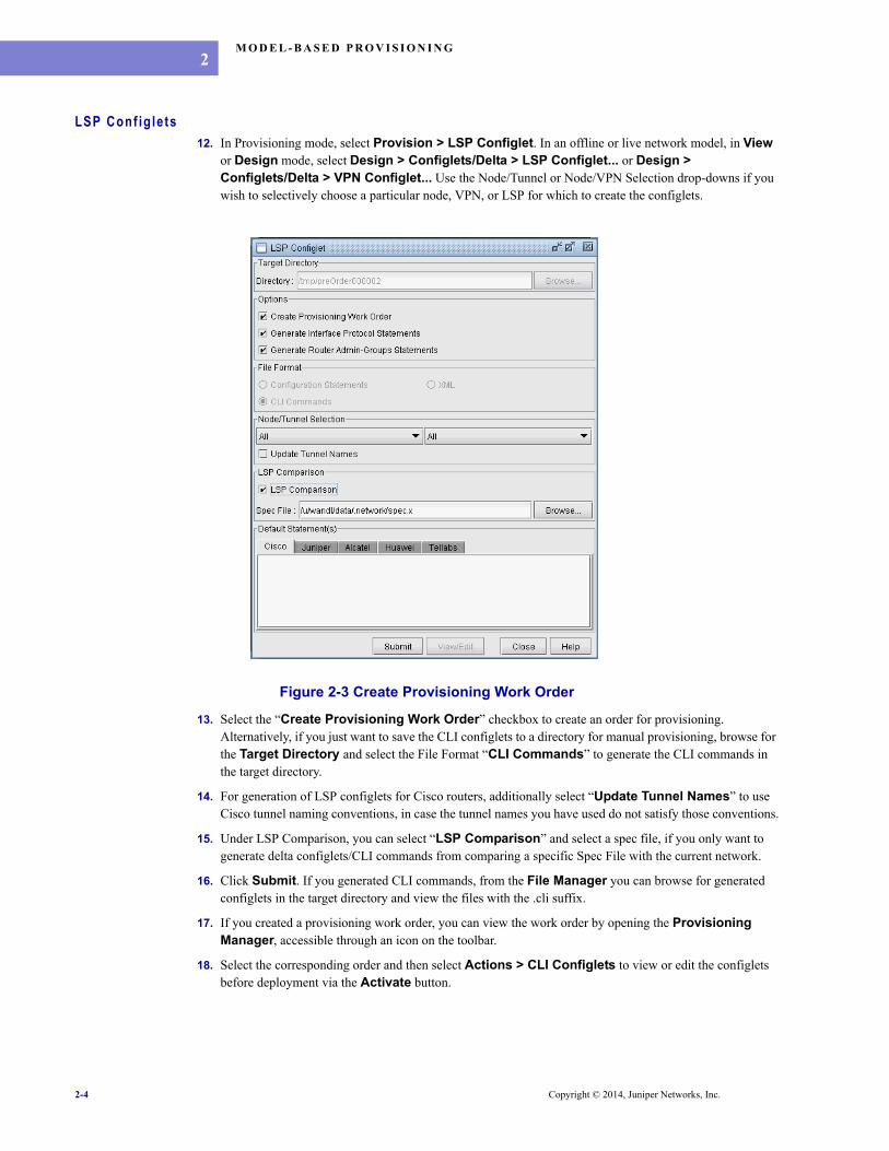
LSP Conf ig le ts12. In Provisioning mode, select Provision > LSP Configlet. In an offline or live network model, in View
or Design mode, select Design > Configlets/Delta > LSP Configlet... or Design > Configlets/Delta > VPN Configlet... Use the Node/Tunnel or Node/VPN Selection drop-downs if you wish to selectively choose a particular node, VPN, or LSP for which to create the configlets.
Figure 2-3 Create Provisioning Work Order
13. Select the “Create Provisioning Work Order” checkbox to create an order for provisioning. Alternatively, if you just want to save the CLI configlets to a directory for manual provisioning, browse for the Target Directory and select the File Format “CLI Commands” to generate the CLI commands in the target directory.
14. For generation of LSP configlets for Cisco routers, additionally select “Update Tunnel Names” to use Cisco tunnel naming conventions, in case the tunnel names you have used do not satisfy those conventions.
15. Under LSP Comparison, you can select “LSP Comparison” and select a spec file, if you only want to generate delta configlets/CLI commands from comparing a specific Spec File with the current network.
16. Click Submit. If you generated CLI commands, from the File Manager you can browse for generated configlets in the target directory and view the files with the .cli suffix.
17. If you created a provisioning work order, you can view the work order by opening the Provisioning Manager, accessible through an icon on the toolbar.
18. Select the corresponding order and then select Actions > CLI Configlets to view or edit the configlets before deployment via the Activate button.
2-4 Copyright © 2014, Juniper Networks, Inc.

M O D E L - B A S E D P R O V I S I O N I N G
. . . . .
VPN Conf ig le ts19. In View or Design mode, select Design > Configlets/Delta > VPN Configlet...
Figure 2-4 VPN Configlet
20. Select “Create Provisioning Work Order”
21. Select “CLI Commands” to generate the CLI commands to be pushed into the network devices. Select “Delta Statements only” to generate the CLI only for changes to the config.
22. Under Node/VPN Selection, you can filter for specific nodes or VPNs of interest for which to generate the order.
23. Under VPN Comparison, you can select “VPN Comparison” and select a spec file, if you only want to generate delta configlets/CLI commands from comparing a specific Spec File with the current network.
24. Click Submit to generate the provisioning order.
25. If you created a provisioning work order, you can view the work order by opening the Provisioning Manager, accessible through an icon on the toolbar.
26. Select the corresponding order and then select Actions > CLI Configlets to view or edit the configlets before deployment via the Activate button.
Copyright © 2014, Juniper Networks, Inc. 2-5

M O D E L - B A S E D P R O V I S I O N I N G2
Switch Conf ig le ts27. In View or Design mode, select Design > Configlets/Delta > Switch Configlet...
Figure 2-5 Switch Configlet
28. Select “Create Provisioning Work Order”
29. Select “CLI Commands” to generate the CLI commands to be pushed into the network devices. Select “Delta Statements only” to generate the CLI only for changes to the config.
30. Under Node/VLAN Selection, you can filter for specific nodes or VLANs of interest for which to generate the order.
31. Under VLAN Comparison, you can select “VLAN Comparison” and select a spec file, if you only want to generate delta configlets/CLI commands from comparing a specific Spec File with the current network.
32. Click Submit to generate the provisioning order.
33. If you created a provisioning work order, you can view the work order by opening the Provisioning Manager, accessible through an icon on the toolbar.
34. Select the corresponding order and then select Actions > CLI Configlets to view or edit the configlets before deployment via the Activate button.
VLAN and VPN Windows35. From the Modify > Services > VLAN, or Network > Services > VLAN, windows, an order can be
created for an individual VLAN or VPN. Select the desired VPN or VLAN from the left hand pane, and click the Detailed tab from the upper right pane.
36. Select Actions > Show All Configlets...
37. From the VPN Configlets or VLAN Configlets window, click the “New Provisioning Order” button.
Saving Changes38. After you are done with the modifications, switch to Design mode.. You can save your changes from File
> Save Network... and select a new directory or runcode.
2-6 Copyright © 2014, Juniper Networks, Inc.
M O D E L - B A S E D P R O V I S I O N I N G
. . . . .
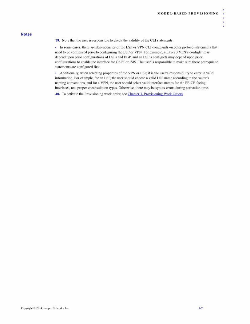
Notes39. Note that the user is responsible to check the validity of the CLI statements.
• In some cases, there are dependencies of the LSP or VPN CLI commands on other protocol statements that need to be configured prior to configuring the LSP or VPN. For example, a Layer 3 VPN’s configlet may depend upon prior configurations of LSPs and BGP, and an LSP’s configlets may depend upon prior configurations to enable the interface for OSPF or ISIS. The user is responsible to make sure these prerequisite statements are configured first.
• Additionally, when selecting properties of the VPN or LSP, it is the user’s responsibility to enter in valid information. For example, for an LSP, the user should choose a valid LSP name according to the router’s naming conventions, and for a VPN, the user should select valid interface names for the PE-CE facing interfaces, and proper encapsulation types. Otherwise, there may be syntax errors during activation time.
40. To activate the Provisioning work order, see Chapter 3, Provisioning Work Orders.
Copyright © 2014, Juniper Networks, Inc. 2-7

M O D E L - B A S E D P R O V I S I O N I N G2
2-8 Copyright © 2014, Juniper Networks, Inc.

. . . . .
. . . . . . . . . . . . . . . . . . . . . . . . . . . . . . . . . . .PROVISIONING WORK ORDERS 3
nce a provisioning work order is generated, the next step is to activate it and monitor it. Once the provisioning is complete, users can view the updated network topology and configuration file changes. With the fault management module, users can additionally monitor the events resulting
from network changes.
Prerequis i tesPrior to beginning this task, you must have a live network or a network model created from config files in your network. You should also have connectivity to your router network. See the Getting Started Guide for instructions to get connected to your router network.
Related Documentat ionFor an overview of IP/MPLSView or for a detailed description of each IP/MPLSView feature and the use of each IP/MPLSView window, refer to the Design & Planning Guide, General Reference Guide, or Router User Guide.
For information on customer service provisioning, refer to Chapter 5, Customer Service Provisioning.
Out l ine1. Activating an Order on page 3-1.
2. Rescheduling an order on page 3-8
3. Appending Configlets on page 3-8
4. Manually Creating a Provisioning Order on page 3-8
Deta i led Procedures
Act ivat ing an Order1. Once a work order has been created, select Provision > Provisioning Manager to see it, or select the
Provisioning Manager icon on the toolbar. After creating a work order, a new entry will be added to the Provisioning window of Pending status.
Figure 3-1 Provisioning Window
2. Note that this Provisioning table can be saved by selecting Actions > Save Table.
O
Copyright © 2014, Juniper Networks, Inc. 3-1

P R O V I S I O N I N G WO R K O R D E R S3
3. Review the configlets to be deployed by selecting Actions > CLI Configlets, and make any necessary modifications. An asterisk will be displayed next to the device if a modification has been made that has not yet been saved. Click the Save button to save the modification to this device, or Save All to save modifications made to all devices in this window.
Figure 3-2 Reviewing Configlets
3-2 Copyright © 2014, Juniper Networks, Inc.

P R O V I S I O N I N G WO R K O R D E R S
. . . . .
A U T H O R I Z I N G A N D A C T I V A T I N G A N O R D E R4. Next, the provisioning order must be authorized by someone who is assigned authorization privileges fromthe Advanced User Administration tool. If you approve of the order and have the authorization privilege, click the “Authorize” button. Then click “Approve” to approve of the order (or “Disapprove” to reject the order).
5. Consequently, the “Authorize” button will change into the “Activate” button. Click the “Activate” button to activate the order.
6. The Activate Configlets window will be displayed. You can enter in a change tracking note, as well as the timeout and number of concurrent jobs to push at the same time.
Figure 3-3 Activate Configlets
The Activation Option allows you to specify what to do in the case of failure.
• Try activating all accessible device(s): Even though activation fails on one device, the program will still continue activation on other devices
• Stop activation if failure detected: Once a failure is detected, the program will not continue to access additional devices
• Stop and rollback automatically if failure detected: Once a failure is detected, the program will not continue to access additional devices. For the devices already activated, the program will try to rollback the statements on that device.
7. Note that there are certain responses from the device that the program recognizes as errors. However, in some cases, you would have to define what strings would be recognized as errors by a partial string match. To do so, modify the file /u/wandl/db/config/proverrmap.txt
The line contains the vendor family followed by the partial error string, e.g.,
CISCO,Configuring IP routing on a LAN subinterface is only allowed if
Copyright © 2014, Juniper Networks, Inc. 3-3

P R O V I S I O N I N G WO R K O R D E R S3
8. Click Next to view the Commit Option window. In this window you can specify per device which commit options to use. For example, for a router with dual routing engines, you may want to use the “commit synchronize” command instead of “commit”, or you may want to commit with a comment.
Figure 3-4 Commit Options
9. Click Next to reach the Login/Password step. Click a row to optionally specify different login/password information than that stored within the Router Profile. You can also click the Test Connectivity button in the middle of this window to test router connectivity prior to activation.
Figure 3-5 Login/Password Options
10. Click Next. At the final confirmation, click Activate to continue activating the order.
11. Once the order is in progress, you can see the status by looking at the progress dialog.
12. After the task is complete, the status dialog will close and you will be prompted as to whether or not to recollect the configuration files now that they have changed.
3-4 Copyright © 2014, Juniper Networks, Inc.

P R O V I S I O N I N G WO R K O R D E R S
. . . . .
Figure 3-6 Data to collect
13. To suppress this prompt to recollect the network, you can add the parameter CustSvcUpdate=0 to /u/wandl/db/misc/dparam.txt. If this parameter file does not already exist, you can add it. One case in which this may be desirable is if you wish to use instead the Network Config Data Collection task to collect only a subset of the network.
14. If the task fails or if it succeeds only partially, check the log tab to see what went wrong. In this case, you can modify the work order to be in the Pending state, modify the configlets as needed from Actions > CLI Configlets, and then resubmit the order.
R E C O L L E C T I N G A N D V E R I F Y I N G T H E N E T W O R K15. After successfully submitting the order and scheduling the live update, select Admin > Task Manager to
check the status of the new task. Once it is completed, select Provision > Overwrite with Live Network to update the current provisioning network to the live network.
16. During the activation, a status window will display the progress of the provisioning order.
Copyright © 2014, Juniper Networks, Inc. 3-5

P R O V I S I O N I N G WO R K O R D E R S3
Figure 3-7 Provisioning Status
17. Once the order is completed, the status window will be closed. To review the changes made, click on the “Note & Log” tab for the appropriate entry in the Provisioning window, and select the link for a particular router to view the log of the commands executed on that router.
Figure 3-8 Log of Executed Router Commands
18. The status of the order will change from Pending to one of the following:
• Deployed: The provisioning for all routers succeeded
• Discrepancy: The provisioning for at least one router failed.
• Rejected: The provisioning for all routers failed.
3-6 Copyright © 2014, Juniper Networks, Inc.
P R O V I S I O N I N G WO R K O R D E R S
. . . . .
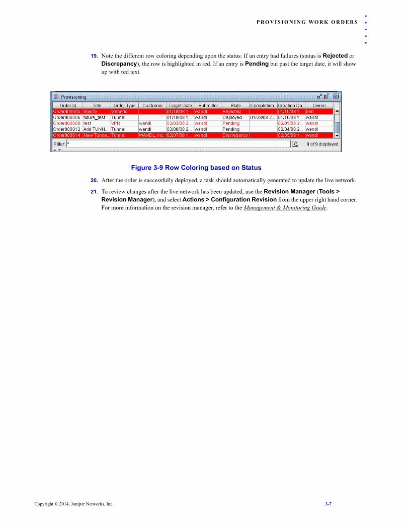
19. Note the different row coloring depending upon the status: If an entry had failures (status is Rejected orDiscrepancy), the row is highlighted in red. If an entry is Pending but past the target date, it will show up with red text.
Figure 3-9 Row Coloring based on Status
20. After the order is successfully deployed, a task should automatically generated to update the live network.
21. To review changes after the live network has been updated, use the Revision Manager (Tools > Revision Manager), and select Actions > Configuration Revision from the upper right hand corner. For more information on the revision manager, refer to the Management & Monitoring Guide.
Copyright © 2014, Juniper Networks, Inc. 3-7
P R O V I S I O N I N G WO R K O R D E R S3
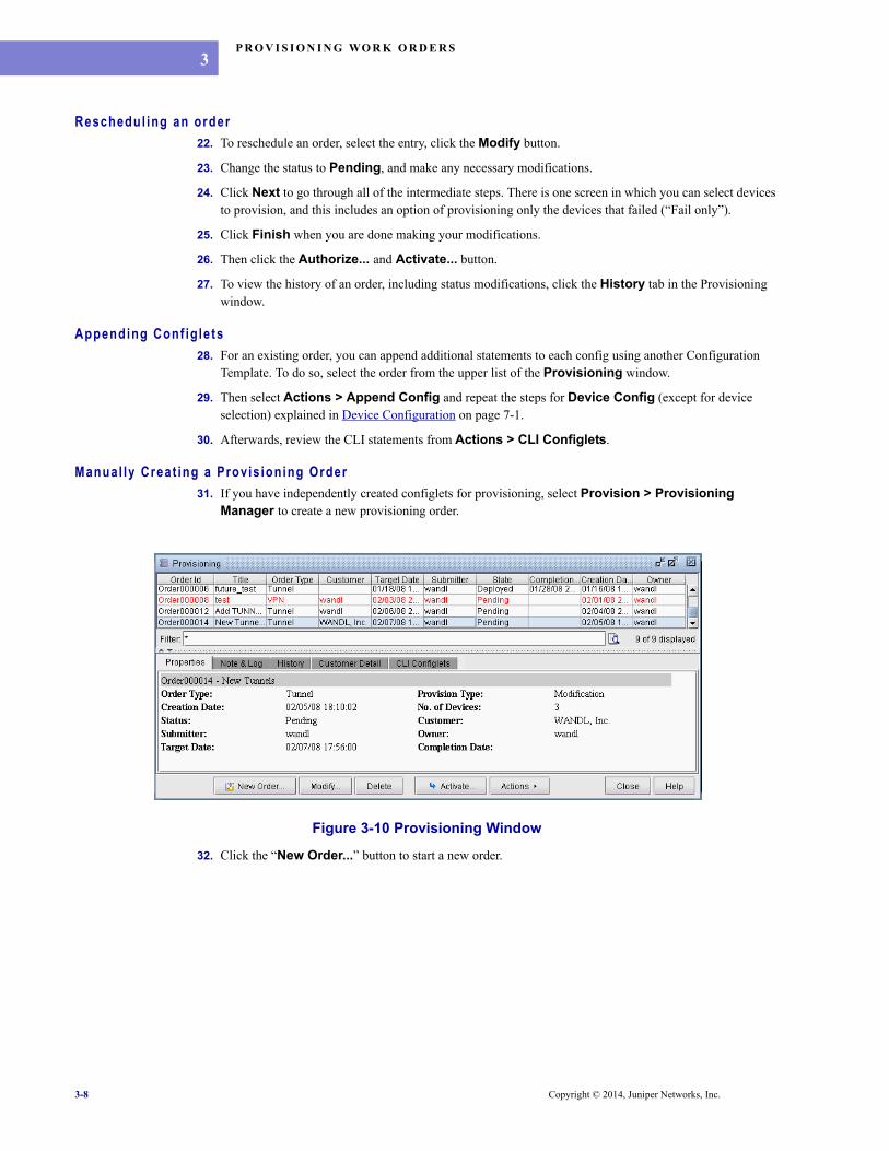
Reschedul ing an order22. To reschedule an order, select the entry, click the Modify button.
23. Change the status to Pending, and make any necessary modifications.
24. Click Next to go through all of the intermediate steps. There is one screen in which you can select devices to provision, and this includes an option of provisioning only the devices that failed (“Fail only”).
25. Click Finish when you are done making your modifications.
26. Then click the Authorize... and Activate... button.
27. To view the history of an order, including status modifications, click the History tab in the Provisioning window.
Appending Conf igle ts28. For an existing order, you can append additional statements to each config using another Configuration
Template. To do so, select the order from the upper list of the Provisioning window.
29. Then select Actions > Append Config and repeat the steps for Device Config (except for device selection) explained in Device Configuration on page 7-1.
30. Afterwards, review the CLI statements from Actions > CLI Configlets.
Manual ly Creat ing a Provis ioning Order31. If you have independently created configlets for provisioning, select Provision > Provisioning
Manager to create a new provisioning order.
Figure 3-10 Provisioning Window
32. Click the “New Order...” button to start a new order.
3-8 Copyright © 2014, Juniper Networks, Inc.

P R O V I S I O N I N G WO R K O R D E R S
. . . . .
Figure 3-11 Adding a New Work Order
33. Enter the Title, Work Order Type (VPN, Tunnel, or Generic), Provision Type (Addition, Modification, Deletion), and Target Date. Note that these fields are for information purposes only. Click Next to continue.
34. In the “Customer Information” screen, optionally enter in the customer contact information. Click Next.
Figure 3-12 Customer Information
35. In the “Choose Devices” screen, select from the available devices and click “Add->” to move them to the right side list, “Selected Devices”. Use the drop-down box to filter on devices of the appropriate hardware vendor/model. Click Next to continue.
Copyright © 2014, Juniper Networks, Inc. 3-9

P R O V I S I O N I N G WO R K O R D E R S3
Figure 3-13 Choose Devices
36. In the “Choose Configlets” screen, the configlet path is automatically populated if possible with generated configlets of the /u/wandl/data/.network/LSP or /u/wandl/data/.network/VPN directory. If this path is incorrect, e.g., you generated the configlets in another directory, you can change the path for an entry. Select a row, click “Browse...”, reenter the path under Configlet Path, and then click the Update button. Check that you have selected the command line files that end with the suffix .cli.
Figure 3-14 Choose Configlets
If necessary, you can still add or remove routers from this screen by selecting the desired router and clicking the Add or Remove button.
37. Click the Finish button when you are finished creating the work order.
Not i f icat ion Emai ls for Prov is ion Work OrdersWhen work orders execute or when a provisioning task’s status changes (e.g., for task creation, modification, authorization, or activation), a notification email can be sent. From the provisioning window, select Actions > Options to enter in the email addresses. Alternatively, this option is enabled via the entry MPLS_PROVISIONING_EMAIL_RECIPIENT=”[email protected]” in the file /u/wandl/bin/mplsenvsetup.sh. Multiple email addresses can be listed separated by comma.
3-10 Copyright © 2014, Juniper Networks, Inc.

. . . . .
. . . . . . . . . . . . . . . . . . . . . . . . . . . . . . . . . . .CUSTOMER SERVICE SETUP 4
his chapter describes how to perform setup prior to a customer service provisioning.
Prerequis i tesPrior to beginning this task, users should have scheduled a live network collection, including the collection of config and switch CLI information.
Related Documentat ionFor information on how to set up the live network, refer to the Management & Monitoring Guide.
For instructions on viewing and modifying VPN information, refer to the Router Guide.
Out l ine1. Creating a Customer Service Order Based on Templates on page 4-2: In the Provisioning network, create a
new customer service, defining the VPN and VLAN parameters, as well as the topology. Create a provisioning work order. Check the configlets and activate the work order.
2. Setup Customer on page 4-4
3. Setup Customer Sites on page 4-4
4. Setup PE & CE Nodes on page 4-6
5. Setup PE & CE Links on page 4-8
6. Setup Regions on page 4-5
TerminologyThe terminology NPE, NCE, UPE, and CE are defined as follows:
• NPE: Network-facing Provider Edge device
• NCE: Network-facing Customer Edge device
• UPE: User-facing Provide Edge device
• CE: Customer Edge device
The following is an example of an end-to-end VLAN-VPLS-VLAN network.
Figure 4-1 End-to-End VPLS
T
Copyright © 2014, Juniper Networks, Inc. 4-1
C U S T O M E R S E R V I C E S E T U P4
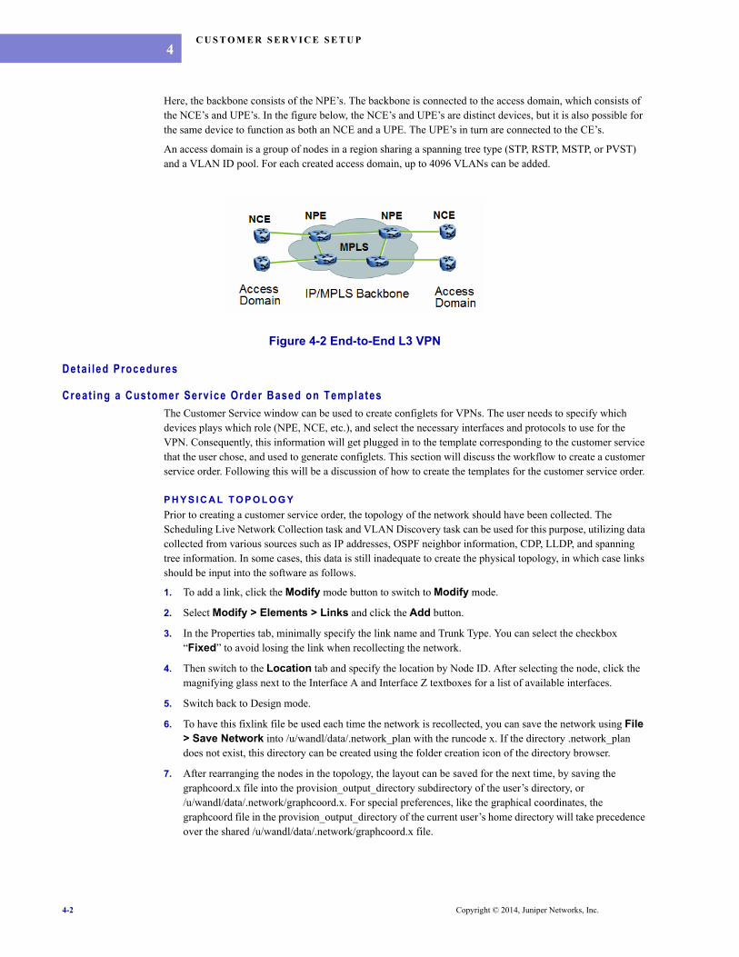
Here, the backbone consists of the NPE’s. The backbone is connected to the access domain, which consists of the NCE’s and UPE’s. In the figure below, the NCE’s and UPE’s are distinct devices, but it is also possible for the same device to function as both an NCE and a UPE. The UPE’s in turn are connected to the CE’s.
An access domain is a group of nodes in a region sharing a spanning tree type (STP, RSTP, MSTP, or PVST) and a VLAN ID pool. For each created access domain, up to 4096 VLANs can be added.
Figure 4-2 End-to-End L3 VPN
Deta i led Procedures
Creat ing a Customer Serv ice Order Based on TemplatesThe Customer Service window can be used to create configlets for VPNs. The user needs to specify which devices plays which role (NPE, NCE, etc.), and select the necessary interfaces and protocols to use for the VPN. Consequently, this information will get plugged in to the template corresponding to the customer service that the user chose, and used to generate configlets. This section will discuss the workflow to create a customer service order. Following this will be a discussion of how to create the templates for the customer service order.
P H Y S I C A L T O P O L O G YPrior to creating a customer service order, the topology of the network should have been collected. The Scheduling Live Network Collection task and VLAN Discovery task can be used for this purpose, utilizing data collected from various sources such as IP addresses, OSPF neighbor information, CDP, LLDP, and spanning tree information. In some cases, this data is still inadequate to create the physical topology, in which case links should be input into the software as follows.
1. To add a link, click the Modify mode button to switch to Modify mode.
2. Select Modify > Elements > Links and click the Add button.
3. In the Properties tab, minimally specify the link name and Trunk Type. You can select the checkbox “Fixed” to avoid losing the link when recollecting the network.
4. Then switch to the Location tab and specify the location by Node ID. After selecting the node, click the magnifying glass next to the Interface A and Interface Z textboxes for a list of available interfaces.
5. Switch back to Design mode.
6. To have this fixlink file be used each time the network is recollected, you can save the network using File > Save Network into /u/wandl/data/.network_plan with the runcode x. If the directory .network_plan does not exist, this directory can be created using the folder creation icon of the directory browser.
7. After rearranging the nodes in the topology, the layout can be saved for the next time, by saving the graphcoord.x file into the provision_output_directory subdirectory of the user’s directory, or /u/wandl/data/.network/graphcoord.x. For special preferences, like the graphical coordinates, the graphcoord file in the provision_output_directory of the current user’s home directory will take precedence over the shared /u/wandl/data/.network/graphcoord.x file.
4-2 Copyright © 2014, Juniper Networks, Inc.

C U S T O M E R S E R V I C E S E T U P
. . . . .
C U S T O M E R S E R V I C E , V P N , A N D I N T E R F A C E P A R A M E T E R S8. Select the desired Customer Service Template, e.g., sample:FullMeshL3VPN.Configlets for a customer service order consist of (a) VPN-related statements, provided in the VPN template, and (b) interface-related statements, specified in the interface model template. The Customer Service Template is the master project template that decides which VPN templates and interface templates to use for a customer service order.
The Customer Service Template “sample:FullMeshL3VPN” corresponds to the following template: “/u/wandl/data/templates/sample/service/CustomerService/UserInterface/Generic/FullMeshL3VPN” The first word “sample” specifies the template directory /u/wandl/data/templates/sample and the second word “FullMeshL3VPN” specifies the specific template “FullMeshL3VPN”.
9. In the VPN Parameters section, specify the VPN template and the VPN-related parameters. In some cases, the selection of the VPN template may be fixed by the Customer Service Template. In other cases, a default template is provided which can be modified.
The VPN template “sample:FullMeshL3VPN” corresponds to the following template directory: “/u/wandl/data/templates/sample/service/VPN/FullMeshL3VPN/. Depending upon the device’s vendor, the template under the CiscoIOS or Junos directory will be used.
Note that some values, such as the Route Distinguisher, and Route Targets, can be configured according to the templates, to be dependent upon other values. For the sample template’s FullMeshL3VPN template, when the AS is selected, a value will be auto-populated for the Route Distinguisher, export route target, and import route target.
10. In the Access Layer Parameters section, if applicable, specify the access layer parameters by selecting the “Config Access Layer” checkbox. (This option is available if the user selects the Customer Service Template: Default”.) Then specify a VLAN name, VLAN ID, and VLAN template.
11. In the Interface Model Templates section, specify the interface templates to use for the PE-CE interfaces. In some cases, the template selection may be fixed by the Customer Service Template. There can be template selections for up to 4 different categories of interfaces, depending upon whether it is the NPE, NCE, UPE, or CE, that needs configuring.
For Layer 3 VPN, the following interface templates may be used.
• Networking facing PE > CE interface (NPE->NCE): The NPE interface facing the NCE
• Networking facing CE > PE interface (NCE->NPE): The NCE interface facing the NPE
Here, the interface template “sample:FullMeshL3VPN” corresponds to the following template directory: “/u/wandl/data/templates/sample/service/Interface/FullMeshL3VPN/. Depending upon the device’s vendor, the template under the CiscoIOS or Junos directory will be used.
In the case of VPLS, the following additional interface templates may also be applicable:
• User facing PE > CE interface (UPE->CE): The UPE interface facing the CE
• User facing CE > PE interface (CE->UPE). The CE interface facing the UPE.
Create Customer Service12. Select File > Open Provisioning Network, or select the Provision icon from the welcome window.
13. Under the Setup menu can be seen the following menus:
• Template Design
• PE & CE Nodes
• PE & CE Links
• Customers
• Customer Sites
Copyright © 2014, Juniper Networks, Inc. 4-3

C U S T O M E R S E R V I C E S E T U P4
• Regions
Setup Customer14. Select Setup > Customers. Then select the Add button.
Figure 4-3 Customer Setup
15. This window allow users to create a Customer. Created Customers will be then available for selection when adding PE/CE nodes (Setup > PE & CE Nodes) and creating VPN (Provision > VPN)
Setup Customer S i tes16. Next, select Customer Sites from the Setup menu on the left pane, and then click Add.
Figure 4-4 Setup PE & CE Links
17. This window allow users to create a customer site. Created customer sites will be available for selection when adding PE/CE nodes (Setup > PE & CE Nodes)
4-4 Copyright © 2014, Juniper Networks, Inc.

C U S T O M E R S E R V I C E S E T U P
. . . . .
Setup Regions18. This window allows users to create a Region. Created Regions will be available for selection when adding PE/CE nodes (Setup > PE & CE Nodes)
Figure 4-5 Example Region Setup
Copyright © 2014, Juniper Networks, Inc. 4-5

C U S T O M E R S E R V I C E S E T U P4
Setup PE & CE Nodes19. Select PE & CE Nodes. Then select the Add button to open the following window.
Figure 4-6 Setup PE & CE Nodes
20. While the setup is highly recommended to setup for easier reuse in future provisioning orders. This window allow user to:
• Manually add a node. For example, You can manually add CE that is not collected in the live network. This can be typed in or selected from the drop-down menu. Consequently, some of the known fields will be populated, such as the related Autonomous System (AS) number.
• Specify Yes or No as to whether a node is Managed or Unmanaged. Only managed nodes will be counted against the license’s Provisioning node count and can have configlets generated.
• Under Role, specify whether a node is a PE or CE. Specified PE/CE nodes will be available for selection when designating links between PE and CE nodes (Setup > PE & CE Links), and creating VPNs (Provision > VPN)
• Specify which customer a node belongs to. You need to create customer first in Setup > Customers• Specify which region a node belongs to. You need to create region first in Setup > Regions
• Specify which site a customer belongs to. You need to create sites first in Setup > Customer Sites21. The following is an example setup of PE and CE nodes.
Figure 4-7 Setup
4-6 Copyright © 2014, Juniper Networks, Inc.

C U S T O M E R S E R V I C E S E T U P
. . . . .
L O C K I N G M E C H A N I S M22. Note that there is a lock icon in the upper right hand corner. When selecting this icon, the table being“checked out” will change to the color red. This locks the table to avoid conflicts with other users.
Figure 4-8 Locking the Table
Copyright © 2014, Juniper Networks, Inc. 4-7

C U S T O M E R S E R V I C E S E T U P4
Setup PE & CE L inks23. Next, select PE & CE Links from the Setup menu on the left pane, and then click Add.
Figure 4-9 Setup PE & CE Links
24. This window allows the user to designate a link between a PE and CE by choosing a PE, PE interface, CE and CE interface. Designated PE & CE links will then be available for selection when creating VPN (Provision > VPN)
25. The following is an example Link setup window.
Figure 4-10 Example PE & CE Link Setup
4-8 Copyright © 2014, Juniper Networks, Inc.

. . . . .
. . . . . . . . . . . . . . . . . . . . . . . . . . . . . . . . . . .CUSTOMER SERVICE PROVISIONING 5
his chapter describes how to perform customer service provisioning to set up a VPN service. Once the customer service has been created, configlets/CLI statements can be generated for the service, for activation in the provisioning work order window.
Prerequis i tesPrior to beginning this task, users should have scheduled a live network collection, including the collection of config and switch CLI information.
The customer service templates should be defined, as described in Chapter 6, Customer Service Template Design.
The setup step should also be performed as described in Chapter 4, Customer Service Setup.
Related Documentat ionFor information on how to set up the live network, refer to the Management & Monitoring Guide.
For instructions on viewing and modifying VPN information, refer to the Router Guide.
Out l ine1. Create a VPN Customer Service on page 5-1
2. Defining the Topology on page 5-3
3. Node Assignment on page 5-3
4. Port Assignment Step on page 5-4
5. VPN PE-CE Protocol Selection on page 5-6
6. Creating a Provisioning Work Order on page 5-7
7. Activating the Provisioning Work Order on page 5-9
8. Verification of the New VPN on page 5-9
Deta i led
Create a VPN Customer Serv ice9. Select Setup > Template Design.
10. Select Actions > Change Template Directory. Choose the template directory that contains the templates you will use for this customer service.
11. To set a default template directory, you can set the the parameter “defaulttemplatedir” in /u/wandl/db/misc/dparam.txt prior to opening the provisioning network. Note that this is the specification of a relative directory, relative to /u/wandl/data/templates/
For example, the following would result in a default template directory /u/wandl/data/templates/wandl_template:
defaulttemplatedir= wandl_template
T
Copyright © 2014, Juniper Networks, Inc. 5-1

C U S T O M E R S E R V I C E P R O V I S I O N I N G5
Figure 5-1 Select the Provisioning Template Directory
12. Click OK.
13. Select Provision > VPN to open the IP VPN window.
14. Click Add to open the Add VPN window.
15. Select the Customer, which should have been created during the Setup step, as explained in Chapter 4, Customer Service Setup.
16. Select the desired Customer Service Template from the list.
17. Fill in any applicable values, such as the Autonomous System (AS) value.
Figure 5-2 VPN Parameters
18. Click Next to start defining the topology.
5-2 Copyright © 2014, Juniper Networks, Inc.

C U S T O M E R S E R V I C E P R O V I S I O N I N G
. . . . .
Def in ing the TopologyThe next step is to specify the topology details. This involves specifying the PE and CE. In more complex topologies, this may involve specifying the NPE, NCE, UPE, and CE, as well as the links between the NPE and NCE and the links between the UPE and CE.
Figure 5-3 Customer Service Topology Window
19. Select Type: Provider Edge (PE) and Type:Customer Edge (CE) or any other available category for your type of VPN, to add any additional PE’s and CE’s from the Members list (left) to the Selected list (right).
20. The AS filter in the upper right corner of the Members list can be selected to change the AS.
21. Use the Funnel icon to filter for only the nodes added during the Setup step as described in Chapter 4, Customer Service Setup.. Undo the Funnel icon to show all relevant nodes.
22. Click Next to proceed.
Node Assignment23. In the following Node Assignment step, the PEs will be listed.
Figure 5-4 Node Assignment
24. To modify individual PE parameters, select the entry for that PE and click Modify.
Copyright © 2014, Juniper Networks, Inc. 5-3

C U S T O M E R S E R V I C E P R O V I S I O N I N G5
Figure 5-5 Modify PE Node
25. In this example, the RD is based on the LOOPBACK, and you can use the magnifying glass next to the RD, to specify a specific Loopback to chose for the RD. The Route Distinguisher can support both formats by IP Address or by ID, if defined properly in the templates.
26. The VPN Template is also customizable, in case it is necessary to have different VPN templates for different PE nodes.
Port Assignment Step27. Click Next to enter the Port Assignment step.
Figure 5-6 Port Assignment
28. Here again, you can select a specific port, and click Modify to edit the parameters of the selected port, such as the IP/Mask, VLAN ID, CoS policer, etc. The VLAN Id should usually match the interface name’s VLAN Id. The interface name can be modified to use the same Vlan Id, or vice versa.
5-4 Copyright © 2014, Juniper Networks, Inc.

C U S T O M E R S E R V I C E P R O V I S I O N I N G
. . . . .
Figure 5-7 Modify Interface
29. Click the Advanced tab for additional parameters. Here, you can customize the configlet template that will be used, in case different interfaces require different templates.
Figure 5-8 Modify Interface, Advanced Tab
30. Click OK when you are done modifying the port details.
31. Verify the subinterfaces and the VLAN ID assigned by the wizard. Right-click on the Table Options to add additional columns to the Port Assignment window. If the arrangement looks correct, click “Next.”
Copyright © 2014, Juniper Networks, Inc. 5-5

C U S T O M E R S E R V I C E P R O V I S I O N I N G5
VPN PE-CE Protocol Select ion
Figure 5-9 VPN Details
32. In the following step, you can specify the PE-CE protocol details. Select a PE, and then select the corresponding protocol. If OSPF or Static are selected, then click the magnifying glass to the right to specify details for the OSPF and Static protocols.
33. If you need to add more than one OSPF or Static router definition, then click the Refresh button in the upper right to create a new entry. Select that entry from the table and then add a new OSPF or Static route definition as appropriate.
34. For example, you can select “Static” checkbox and then click the adjacent option to specify the particular details for the static route (the destination IP and the next hop).
Figure 5-10 Static Route
35. You could alternatively select BGP as the PE-CE protocol and then click the adjacent option to specify the particular details for the BGP neighbor, including the Neighbor Node and Neighbor Address. Note that the Neighbor Address here should be modified to be different from the Node IP address. For example, for a /30 link, it is usually different by 1 in the last octet.
5-6 Copyright © 2014, Juniper Networks, Inc.

C U S T O M E R S E R V I C E P R O V I S I O N I N G
. . . . .
Figure 5-11 BGP Neighbor
36. Click OK to make the changes to the PE-CE routing protocol.
37. Once you are finished, click the Finish button. Check the resulting VPN window to ensure that you have everything you need.
Creat ing a Provis ioning Work Order38. Select Provision > VPN and select Summary from the IP VPN window. Right-click the table header to
add the columns Customer and Status. The Planned status indicates a VPN that has been added but not yet provisioned.
Figure 5-12 Planned VPN
39. Double-click the VPN to jump to the VPN-specific view.
40. Then click the Configlets button to open the following window.
Copyright © 2014, Juniper Networks, Inc. 5-7
C U S T O M E R S E R V I C E P R O V I S I O N I N G5
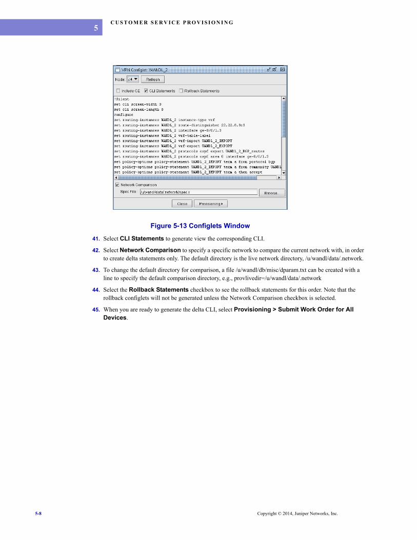
Figure 5-13 Configlets Window
41. Select CLI Statements to generate view the corresponding CLI.
42. Select Network Comparison to specify a specific network to compare the current network with, in order to create delta statements only. The default directory is the live network directory, /u/wandl/data/.network.
43. To change the default directory for comparison, a file /u/wandl/db/misc/dparam.txt can be created with a line to specify the default comparison directory, e.g., provlivedir=/u/wandl/data/.network
44. Select the Rollback Statements checkbox to see the rollback statements for this order. Note that the rollback configlets will not be generated unless the Network Comparison checkbox is selected.
45. When you are ready to generate the delta CLI, select Provisioning > Submit Work Order for All Devices.
5-8 Copyright © 2014, Juniper Networks, Inc.

C U S T O M E R S E R V I C E P R O V I S I O N I N G
. . . . .
Act ivat ing the Provis ioning Work Order46. Open the provisioning manager from Provision > Provisioning Manager to see the new work order.
Figure 5-14 Provisioning Work Order
47. Check the configlets from Actions > CLI Configlets, review the configlets, and make any necessary modifications.
48. The steps for authorization and activation are the same as for the device config orders. For more information on how to authorize and activate an order, refer back to Chapter 3, Provisioning Work Orders.
49. The Provisioning table can be saved by selecting Actions > Save Table.
Ver i f icat ion of the New VPN50. From the web, you can view the new VPN from the Live Network > VPN view.
51. You can verify the end-to-end connectivity using the Diagnostics Manager under Tools > Diagnostics > Diagnostics Manager.
52. Additionally, you can right-click on a node and select “Run CLI” to run selected diagnostics commands. For example, for VPLS, you could choose the command “show vpls connections logical-router all” from the VPLS category. You could also select the devices in the access domain and select the commands “show vlans” and “show vlans detail” from the Switch Commands category.
Copyright © 2014, Juniper Networks, Inc. 5-9

C U S T O M E R S E R V I C E P R O V I S I O N I N G5
5-10 Copyright © 2014, Juniper Networks, Inc.

. . . . .
. . . . . . . . . . . . . . . . . . . . . . . . . . . . . . . . . . .CUSTOMER SERVICE TEMPLATE DESIGN 6
his chapter describes how to design the customer service templateto set up a VPN service.
Prerequis i tesPrior to beginning this task, users should have scheduled a live network collection, including the collection of config and switch CLI information.
Related Documentat ionFor information on how to set up the live network, refer to the Management & Monitoring Guide.
For instructions on viewing and modifying VPN information, refer to the Router Guide.
Out l ine1. Understanding the Customer Service Template Project on page 6-1
2. Creating Customer Service Templates on page 6-3
3. Understanding Customer Service Templates Syntax on page 6-5
4. Understanding VPN and Interface Templates Syntax on page 6-7
Deta i led Procedures
Understanding the Customer Serv ice Template Pro jectThe customer service order is generated from Service Templates which consist of a master file which refers to a VPN template and an interface template.
1. To view the customer service templates, select File > Open Provisioning Network. Select Setup > Template Design.
2. The default project that will be open the first time is the sample project. The current project will be indicated in the window’s title, “Template Design (sample)”.
T
Copyright © 2014, Juniper Networks, Inc. 6-1
C U S T O M E R S E R V I C E TE M P L A T E D E S I G N6
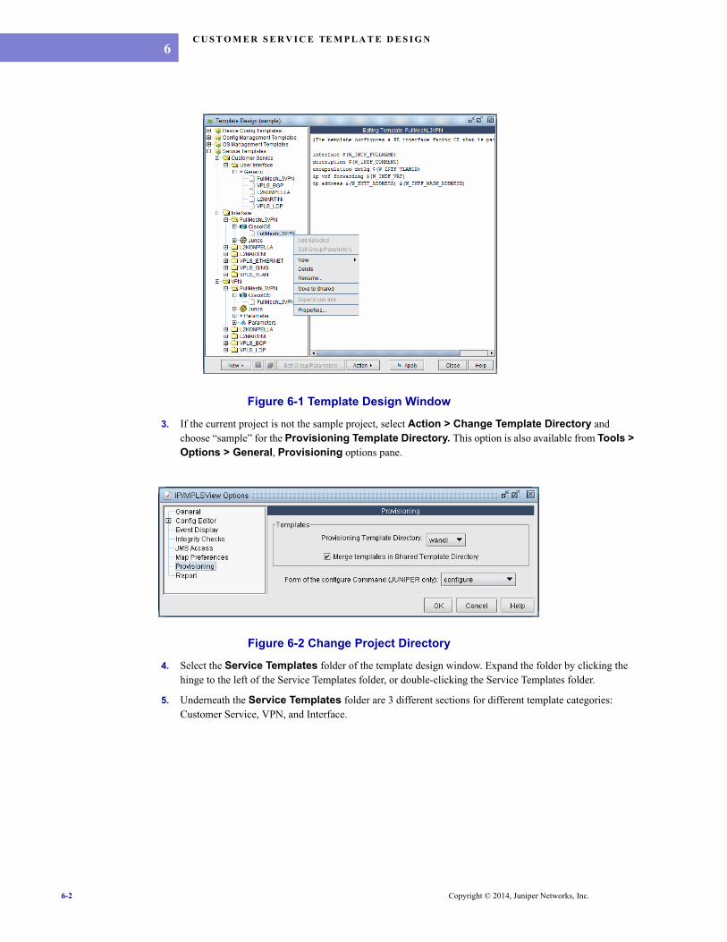
Figure 6-1 Template Design Window
3. If the current project is not the sample project, select Action > Change Template Directory and choose “sample” for the Provisioning Template Directory. This option is also available from Tools > Options > General, Provisioning options pane.
Figure 6-2 Change Project Directory
4. Select the Service Templates folder of the template design window. Expand the folder by clicking the hinge to the left of the Service Templates folder, or double-clicking the Service Templates folder.
5. Underneath the Service Templates folder are 3 different sections for different template categories: Customer Service, VPN, and Interface.
6-2 Copyright © 2014, Juniper Networks, Inc.

C U S T O M E R S E R V I C E TE M P L A T E D E S I G N
. . . . .
T E M P L A T E C A T E G O R Y• Customer Service: This folder contains the master templates. Expand the User Interface and Generic subdirectories. A master template, such as “FullMeshL3VPN” and “VPLS_BGP”, defines which interface or VPN configlet templates will be used for the customer service, as well as special syntax/naming rules that should be followed. For example, select the FullMeshL3VPN customer service template. It indicates that it will use the VPN template (W_VPN_TEMPLATE) and interface template (W_NPE_TEMPLATE) also by the name FullMeshL3VPN. Note that a variable beginning with “W_” denotes a reserved keyword.• Interface: The templates underneath the interface template category are used to define configlet templates for different types of interfaces. For example, a configlet template is created for the PE-CE (NPE-NCE) interface of a Layer 3 VPN. In some cases, such as for VPLS, there can be four different types of interfaces configlet templates: NPE->NCE, NCE->NPE, UPE->CE, or CE->UPE. Notice a subdirectory for the hardware vendor/OS (e.g., CiscoIOS or Junos). IP/MPLSView can automatically detect the hardware type of the relevant device to decide which template to use. The vendor/OS directory contains the actual configlet templates.
• VPN: Defines confliget templates for the PE router, including the definition of the VPN (e.g., the “ip vrf” section for Cisco IOS and the “routing-instances” section for JUNOS) and the PE-CE routing protocols. Notice again for each folder (subcategory), there is a further breakdown into the hardware vendor/OS (e.g., CiscoIOS or Junos).
T E M P L A T E O R G A N I Z A T I O NIn summary, the templates underneath the Service Templates section are organized in the following hierarchy:
Service Templates > Template Category > Subcategory > Vendor/OS > Template NameFor Customer Service, there is no Vendor/OS, so it appears as follows:
Service Templates > Customer Service > User Interface > Generic > Template NameFor one customer service, such as FullMeshL3VPN, you could have the following associated templates. It is recommended, but not required, to use similar subcategory names and template names across a customer service type (e.g., L3VPN or VPLS) in order to quickly identify which templates belong together. It is the master template in the Customer Service folder which ultimately defines which interface templates and VPN templates will be used together, along with special syntax/naming rules.
• Service Templates > Customer Service > User Interface > Generic > FullMeshL3VPN• Service Templates > Interface > FullMeshL3VPN > CiscoIOS > FullMeshL3VPN• Service Templates > Interface > FullMeshL3VPN > Junos > FullMeshL3VPN• Service Templates > VPN > FullMeshL3VPN > CiscoIOS > FullMeshL3VPN• Service Templates > VPN > FullMeshL3VPN > Junos > FullMeshL3VPN
Creat ing Customer Service TemplatesCustomer Service Templates should be defined before opening the Customer Service Provisioning wizard.
6. To create a new project, select Setup > Template Design. Then select Action > Create New Template Directory. Enter your project name for your directory, without spaces in the name. The corresponding template directory will be created in /u/wandl/data/templates.
7. To change the current template project, select Action > Change Template Directory to choose the Provisioning Template Directory for your project. (This option can also be acccessed from Tools > Options > General, Provisioning options pane.)
C R E A T I N G A C U S T O M E R S E R V I C E T E M P L A T E8. If the Customer Service folder does not yet exist, right-click on the Service Templates folder and select
New > Configlet. If the Customer Service folder already exists, right-click on it and select New > Configlet.
Copyright © 2014, Juniper Networks, Inc. 6-3

C U S T O M E R S E R V I C E TE M P L A T E D E S I G N6
Figure 6-3 New Configlet Template
9. In the New Configlet Template window, specify a Template Name and description. If you right-clicked over the Customer Service folder in your last step, then the Template Category (CustomerService) and Subcategory (UserInterface) will be automatically filled in. Click OK to continue.
10. You can directly edit in the right pane or copy/paste text into the right pane. Right-click over the right pane to access Cut/Copy/Paste operations as well as Find/Replace, Select All, Show Line Number and Auto Format. Click the Save icon when you are ready to save your edits. You can later delete a configlet template by right-clicking it in the left pane and selecting Remove.
11. The template syntax will be discussed in a later section.
C R E A T I N G A N I N T E R F A C E T E M P L A T E12. To create your first interface template, if the category does not exist yet, right-click on the Service
Templates folder and select New > Configlet and select “Interface” as the Template Category. If the Interface template category already exists, then right-click on the Interface folder, and the Category will be automatically filled in.
13. Select or enter in the Subcategory (e.g., FullMeshL3VPN), and the template name (e.g., MyFullMeshL3VPN), as well as which vendor/OS (e.g., CiscoIOS or Junos). Recall the meaning of the hierarchy for interfaces:
Service Templates > Template Category > Subcategory > Vendor/OS > Template NameService Templates > Interface > FullMeshL3VPN > CiscoIOS > MyFullMeshL3VPN
Figure 6-4 New Configlet Template
6-4 Copyright © 2014, Juniper Networks, Inc.

C U S T O M E R S E R V I C E TE M P L A T E D E S I G N
. . . . .
C R E A T I N G A V P N T E M P L A T E14. To create your first VPN template, if the category does not exist yet, right-click on the Service Templatesfolder and select New > Configlet and select “VPN” as the Template Category. If the VPN template category already exists, then right-click on the VPN folder, and the Category will be automatically filled in.
15. Select or enter in the Subcategory (e.g., FullMeshL3VPN), and the template name (e.g., FullMeshL3VPN), as well as which vendor/OS (e.g., CiscoIOS or Junos). Recall the meaning of the hierarchy for interfaces:
Service Templates > Template Category > Subcategory > Vendor/OS > Template NameService Templates > VPN > FullMeshL3VPN > CiscoIOS > FullMeshL3VPN
Understanding Customer Serv ice Templates Syntax16. The template categories of Interface, Protocol, VPN, and VLAN have similar syntax as the respective
vendor’s configlet. Varying fields in the configlets are replaced by variables/constants that follow WANDL defined naming conventions.
17. Customer Service templates can be deployed for end-to-end provisioning through Customer Service GUI (Modify > Services > Customer Services >Add > Customer Service).
18. The customer service templates follow the same variable naming conventions as the device configuration templates. For the fundamental rules in defining variables in templates, refer back to Configlet Template Syntax on page 8-4.
Figure 6-5 VPN System Template
19. Some additional syntax is used by the Customer Service master template, which is used to define the customer service, and reference the appropriate VPN and interface templates. Below is a sample segment of a customer service template.
Example for Layer 3 VPN:
Copyright © 2014, Juniper Networks, Inc. 6-5

C U S T O M E R S E R V I C E TE M P L A T E D E S I G N6
#This is a comment field# $(GLOBAL-VARIABLE)@include VPN$(W_VPN_TYPE,label=VPN TYPE,fixed=L3VPN)$(W_VPN_NAME)$(W_AS,label=AS)$(ID)$(W_RD,label=ROUTE DISTINGUISHER,format=$(W_AS):$(ID))$(W_eRT,label=EXPORT ROUTE TARGET,format=$(W_AS):$(ID))$(W_iRT,label=IMPORT ROUTE TARGET,format=$(W_AS):$(ID))#$(VPN_DESCRIPTION,format=$(W_VPN_NAME))$(W_VPN_TEMPLATE,fixed=FullMeshL3VPN)$(W_NPE_TEMPLATE,fixed=FullMeshL3VPN)@end include
@include NPE$(TESTVAR)@end include
Example for VPLS:@include VPN $(W_VPN_TYPE, label=VPN TYPE, fixed=VPLS-LDP) $(<variable> , label=<variable-name>, fomat=%xnd) $(<variable> , label=<variable-name>, fomat=$(<variable1):$(<variable2>, label=<variable-name2>)) $(<variable> , label=<variable-name>, fomat=constant:$(<variable2>)) $(<variable> , label=<variable-name>, fomat=constant1:constant2) $( <variable> , label=<variable-name>, fixed= <fixed-value>) @end include
C O M M E N T SAny comments to the template are defined within ‘#’ symbols. These comments are meant only for template writers/readers’ understanding and is not seen in the Customer Service GUI
V A R I A B L E D E C L A R A T I O N A N D D E F I N I T I O NA variable is a means of specifying a property that the user should specify in the Customer Service window. It will often translate into a textbox or selection menu in the Customer Service window.
A variable is declared in the template by the format “$(variable-name)”, where variable-name can be reserved one or a user-defined one.
Variable name that starts with ‘W_’ is recognized as a WANDL reserved variable. Each template type, e.g., VPN or interface, has a defined set of WANDL reserved variables confined to the template type. For WANDL reserved variables, users do not need to worry about specifying the syntax, range, uniqueness checks etc. Similar syntactical rules also apply to constants.
Additional properties can be set for variables by adding comma-separated fields. For example, the following expression indicates that the label for the VPN type selection menu will be printed as “VPN Type” and that the selected option will be “L3VPN” and unchangeable:
$(W_VPN_TYPE,label=VPN TYPE,fixed=L3VPN)
As another example, the following expression indicates that the Route Distinguisher reserved variable will have a specific format which is a combination of the AS reserved variable which users can select from the Customer Service GUI and an ID. The ID here is not prefixed with W_, indicating that it is not a WANDL reserved variable. Users will have a textbox to enter in the value for the ID, and that will get used to define the Route Distinguisher.
$(W_RD,label=ROUTE DISTINGUISHER,format=$(W_AS):$(ID))
For more on the WANDL reserved variables and on more syntactical expressions, see Appendix on page 6-9
6-6 Copyright © 2014, Juniper Networks, Inc.

C U S T O M E R S E R V I C E TE M P L A T E D E S I G N
. . . . .
@ I N C L U D E B L O C K SIn the customer service template, variables are defined within include blocks, beginning with “@include category” where the category can be substituted by the category type such as “VPN” or “VLAN” and ending with “@end include”. Reserved variables, starting with W_ for the customer service template type are inherited into the block with similar block type. Eg: If the block type is VPN, then all the reserved variables for VPN template type are inherited into the VPN block.The include block for particular interfaces, e.g., @include NPE, can be used to specify additional user-defined Template Parameters for interfaces.
Note that variables that fall outside the @include section are global variables.
S P E C I F Y I N G C O R R E S P O N D I N G T E M P L A T E T Y P E SA customer service template can reference specific VPN, VLAN and Interface template types to be used with the Customer Service template. The reserved names W_VPN_TEMPLATE and W_NPE_TEMPLATE are example fields that correspond to the “VPN Template” and ‘Network Facing PE>CE Interface’ drop-down menus in Customer Service window.
Understanding VPN and In ter face Templates Syntax
I N T E R F A C E T E M P L A T EThe following is an example interface template for the interface configlet on the PE facing the CE. Again, we see the use of WANDL reserved variables enclosed within “$(“ and “)”. In this case, the template looks very similar to a configlet, but with variables that need to be substituted when using the Customer Service window.
interface $(W_INTF_FULLNAME)description $(W_INTF_COMMENT)encapsulation dot1q $(W_INTF_VLANID)ip vrf forwarding $(W_INTF_VRF)ip address $(W_INTF_ADDRESS) $(W_INTF_MASK_ADDRESS)
V P N T E M P L A T EThe following is a sample section from the VPN template. Notice the use of the “@section” and “@end section” pair of commands to specify a block that may have a variable number of entries depending upon the number of BGP neighbors.
ip vrf $(W_VPN_NAME)description $(VPN_DESCRIPTION) rd $(W_RD) route-target export $(W_eRT) route-target import $(W_iRT)!ip route vrf $(W_VPN_NAME) $(W_VPN_STATIC_PREFIX) $(W_VPN_STATIC_MASK_ADDRESS) $(W_VPN_STATIC_NEXTHOP_ADDRESS) !router bgp $(W_AS) address-family ipv4 vrf $(W_VPN_NAME) no synchronization no auto-summary redistribute ospf $(W_INTF_OSPF_PID) vrf $(W_VPN_NAME) match internal external 1 external 2 redistribute $(W_VPN_CONNECTED) redistribute $(W_VPN_STATIC) redistribute $(W_VPN_RIP)@section ne neighbor $(W_VPN_BGPNBR_ADDRESS) remote-as $(W_VPN_BGPNBR_REMOTEAS) neighbor $(W_VPN_BGPNBR_ADDRESS) as-override neighbor $(W_VPN_BGPNBR_ADDRESS) activate@end section
Copyright © 2014, Juniper Networks, Inc. 6-7

C U S T O M E R S E R V I C E TE M P L A T E D E S I G N6
exit-address-family!Refer to the Appendix on page 6-9 for more details about syntax.
P A R A M E T E R SFor an interface or VPN template, you may include variables which are not WANDL reserved variables. For these variables, you can set specific values. Right-click over the template in the left pane of the Template Design window to select New > Parameter File.
Enter in a name for the parameter file. If there are any non-WANDL variables that are in the template, you will have an opportunity to enter in the corresponding value.
Figure 6-6 Parameters
6-8 Copyright © 2014, Juniper Networks, Inc.

C U S T O M E R S E R V I C E TE M P L A T E D E S I G N
. . . . .
AppendixU S A G E
Usage Syntax Description/Example
Variable’s Existence
if $(W_...) If variable W_... exists
Variable’s Non-Existence
if !$(W_...) If variable W_... does not exist
Variable’s Original Value
$(-W_...)
Used to indicate the original value of the element being compared. This variable is used in the VPN/Interface template. It is used in deletion/modification statements to represent the old value of a variable.
Template Exampleno route-target export $(-W_eRT)rename group $(-W_VPN_BGPNBR_GROUP) to group $(W_VPN_BGPNBR_GROUP)
Configlet exampleno route-target export 88:60062rename routing-instances citi_1 protocols bgp group citi_1 to group testing
And operator if <expression> && <expression> If both expressions are true
Or operator if <expression> || <expression> If either expression is true
Delete Condition @if delete $(W_...)@if end
-or-@if !$(W_...) && $(-W_...)@if end
This condition is used in the VPN/Interface template to allow users to specify statements that will be used for deleting a variable
Template Example@if delete $(W_VPN_BGPNBR_ADDRESS)delete group $(-W_VPN_BGPNBR_GROUP) neighbor $(-W_VPN_BGPNBR_ADDRESS)@end if
Configlet Exampledelete routing-instances citi_1 protocols bgp group citi_1 neighbor 33.33.7.2
Modify Condition @if modify $(W_...)@if end
-or-
@if $(W_...)!=$(-W_...)@if end
This condition is used in the VPN/Interface template to allow user to specify statements that will be used for modifying variables. Use this condition when you need to delete a variable before you are allowed to set a new value.
Template Example@if $(W_RD)!=$(-W_RD) no rd $(-W_RD)@end ifrd $(W_RD)
Configlet Exampleno rd 11.11.11.3:60062rd 11.11.11.3:88
Copyright © 2014, Juniper Networks, Inc. 6-9

C U S T O M E R S E R V I C E TE M P L A T E D E S I G N6
Repeat Block @repeat $(W_...)@end repeat
-or-
@repeat@end repeat
This block is used in the VPN/Interface template to repeat statements when the variable specified following the repeat keyword has multiple values. If the variable is not specified, this block will only repeat statements when all of the variables in the statement have multiple values.
Template Example@repeat $(W_VPN_STATIC_PREFIX)ip route vrf $(W_VRF_NAME) $(W_VPN_STATIC_PREFIX) $(W_VPN_STATIC_MASK_ADDRESS) $(W_VPN_STATIC_NEXTHOP_ADDRESS) @end repeat
Configlet Exampleip route vrf citi_1 33.33.7.8 255.255.255.252 33.33.7.10 ip route vrf citi_1 76.6.7.0 255.255.255.0 33.33.7.10
Section Block @section $(W_...)@end section
Iterate all attributes of W_... variable
Exit Condition @exit
Exit the configlet generation.
This keyword is used in the VPN/Interface template. It is used to terminate the template plug-in so that remaining statements in the template will not be generated. It is normally used inside an if condition to terminate the template plugging-in when ertain conditions are met.
Template Example@if delete $(W_VRF_NAME)no ip vrf $(-W_VRF_NAME)!@exit@end ifip vrf $(W_VRF_NAME)rd $(W_RD)route-target export $(W_eRT)route-target import $(W_iRT)!
Configlet Exampleno ip vrf citi_1!
Variable Becomes Nonexistent
@if !$(W_...) && $(-W_...)@end if
This condition is used in the VPN/Interface template. Statements inside this condition will only be generated when a variable, which formerly had a value, becomes nonexistent.
You can use this to control routes distribution from vrf protocol to BGP, i.e. remove static route from being to distributed into BGP when all static routes is removed from VRF protocol
Template Example@if !$(W_VPN_STATIC) && $(-W_VPN_STATIC) no redistribute $(-W_VPN_STATIC) @end if
Configlet Exampleno redistribute static
Usage Syntax Description/Example
6-10 Copyright © 2014, Juniper Networks, Inc.

C U S T O M E R S E R V I C E TE M P L A T E D E S I G N
. . . . .
Variable is New @if new $(W_...) @end if
-or-
@if $(W_...) && !$(-W_…)@end if
This condition is used in the VPN/Interface template. Statements insides this condition will only be generated when the variable did not formerly exist, but now exists and has a value. This can be used to control routes distribution from vrf protocol to BGP, i.e. redistribute static route into BGP when static routes are defined in VRF protocol
Template Example@if $(W_VPN_STATIC) && !$(-W_VPN_STATIC) redistribute $(W_VPN_STATIC) @end if
Configlet Example redistribute static
Dummy Variable $(W_)
This keyword is used to generate fixed statements at the end of the block when network comparison is checked. In the example, to make sure that exit-address-family is generated when network comparison is checked, put $(W_) after exit-address-family.
Template Examplerouter $(W_VPN_RIP) version 2 address-family ipv4 vrf $(W_VRF_NAME) network $(W_INTF_SUBNET) redistribute bgp $(W_AS) metric 2 exit-address-family $(W_)!
Usage Syntax Description/Example
Copyright © 2014, Juniper Networks, Inc. 6-11

C U S T O M E R S E R V I C E TE M P L A T E D E S I G N6
R E S E R V E D V A R I A B L E S F O R I N T E R F A C E T E M P L A T E T Y P E
Reserved Variable Name - Interface Template Type Description Usage
W_INTF_ADDRESS Interface ip address 1.2.3.4
W_INTF_COMMENT Interface description This is gigabit ethernet
W_INTF_CUSTOMER Customer name
W_INTF_ENCAP Interface encapsulation
W_INTF_ENCAP_IOS Interface encapsulation of a CiscoIOS interface
W_INTF_ENCAP_JUNOS Interface encapsulation of a JUNOS interface
W_INTF_FULLNAME Full name of interface ge-0/0/1.2 on JUNOS, FastEtherent5/0.2 on IOS
W_INTF_HSRP_GROUPW_INTF_HSRP_ADDRESSW_INTF_HSRP_PRIORITY
Hot Standby Router Protocol attributes
W_INTF_INVERSE_MASK Reverse mask in IP format 0.0.0.3
W_INTF_LAYER2 This variable will be equal to 1 if the interface is in switchport mode
W_INTF_L2VPN VPN name for Layer 2 VPN
W_INTF_MASK Subnet mask in number format 24
W_INTF_MASK_ADDRESS Subnet mask in IP format 255.255.255.252
W_INTF_MTU Mtu
W_INTF_NAME Physical interface name ge-0/0/1 on JUNOS, FastEthernet5/0
W_INTF_NAME_UNIT Logical unit of interface 123 in ge-0/0/1.123
W_INTF_OSPF_AREA Ospf area id
W_INTF_OSPF_PID Ospf process id
W_INTF_POLICER_INW_INTF_POLICER_OUT
CoS Policers applied at the interface level for ingress/egress policing. Corresponds to the Policer In and Policer Out fields of the Interface window, Advanced tab.
W_INTF_SUBNET Subnet address 1.2.3.0 for /24 subnet, 1.2.0.0 for /16 subnet
W_INTF_STATUS Operational status of the interface. Can take the following values: active, passive, planned, down, unknown or user-defined.
W_INTF_SW_MODE Layer 2 switch port mode, specified from interface window, Advanced Tab
access or trunk
W_INTF_VCI vci
W_INTF_VCID Circuit ID of layer 2 VPN
W_INTF_VLANID vlanid
W_INTF_VLANINTF Name of the VLAN interface, specified from interface window, Properties tab
Vlan44
W_INTF_VLAN_TAGGING
6-12 Copyright © 2014, Juniper Networks, Inc.
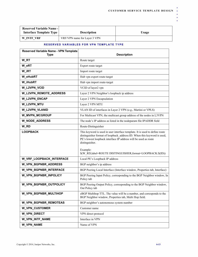
C U S T O M E R S E R V I C E TE M P L A T E D E S I G N
. . . . .
R E S E R V E D V A R I A B L E S F O R V P N T E M P L A T E T Y P E
W_INTF_VRF VRF/VPN name for Layer 3 VPN
Reserved Variable Name - VPN Template Type Description
W_RT Route target
W_eRT Export route target
W_iRT Import route target
W_eHubRT Hub vpn export route-target
W_iHubRT Hub vpn import route-target
W_L2VPN_VCID VCID of layer2 vpn
W_L2VPN_REMOTE_ADDRESS Layer 2 VPN Neighbor’s loopback ip address
W_L2VPN_ENCAP Layer 2 VPN Encapsulation
W_L2VPN_MTU Layer 2 VPN MTU
W_L2VPN_VLANID VLAN ID of interfaces in Layer 2 VPN (e.g., Martini or VPLS)
W_MVPN_MCGROUP For Multicast VPN, the multicast group address of the nodes in L3VPN
W_NODE_ADDRESS The node’s IP address as listed in the nodeparam file IPADDR field
W_RD Route-Distinguisher
LOOPBACK This keyword is used in user interface template. It is used to define route distinguisher format of loopback_address:ID. When this keyword is used, PE’s lowest loopback interface IP address will be used as route distinguisher.
Example:$(W_RD,label=ROUTE DISTINGUISHER,format=LOOPBACK:$(ID))
W_VRF_LOOPBACK_INTERFACE Local PE’s Loopback IP address
W_VPN_BGPNBR_ADDRESS BGP neighbor’s ip address
W_VPN_BGPNBR_INTERFACE BGP Peering Local Interface (Interface window, Properties tab, Interface)
W_VPN_BGPNBR_INPOLICY BGP Peering Input Policy, corresponding to the BGP Neighbor window, In Policy tab
W_VPN_BGPNBR_OUTPOLICY BGP Peering Output Policy, corresponding to the BGP Neighbor window, Out Policy tab
W_VPN_BGPNBR_MULTIHOP eBGP Multihop TTL. The value will be a number, and corresponds to the BGP Neighbor window, Properties tab, Multi Hop field.
W_VPN_BGPNBR_REMOTEAS BGP neighbor’s autonomous system number
W_VPN_CUSTOMER Customer name
W_VPN_DIRECT VPN direct protocol
W_VPN_INTF_NAME Interface in VPN
W_VPN_NAME Name of VPN
Reserved Variable Name - Interface Template Type Description Usage
Copyright © 2014, Juniper Networks, Inc. 6-13

C U S T O M E R S E R V I C E TE M P L A T E D E S I G N6
W_VPN_OSPF_INTF_SUBNET The subnet address of an interface running OSPF protocol.
Example:router $(W_VPN_OSPF) $(W_INTF_OSPF_PID) vrf $(W_VRF_NAME)@repeat $(W_VPN_OSPF_INTF_SUBNET) network $(W_VPN_OSPF_INTF_SUBNET) $(W_INTF_INVERSE_MASK) area $(W_INTF_OSPF_AREA)@end repeat!
W_VPN_OSPF_INTF_NAME The interface running OSPF.
Example:ospf {
area $(W_INTF_OSPF_AREA) { interface $(W_VPN_OSPF_INTF_NAME);
}}
W_VPN_PW_CLASS For Layer 2 Martini VPN, this corresponds to Modify > Services > VPN, Detailed tab, Pseudowire class
W_VPN_SITE Site name of VPN
W_VPN_SITEID Site-id of VPN
W_VPN_REMOTE_SITEID Layer 2 Kompella, remote site ID
W_VPN_SITEPREFERENCE Site preference of VPN. Ranges from 1 to 65535, lowest number is least preference and highest number is highest preference.
W_VPN_SITERANGE Site range of VPN
W_VPN_STATIC_PREFIX Static route prefix
W_VPN_STATIC_MASK Static route mask in number format
W_VPN_STATIC_MASK_ADDRESS Static route mask in IP address format
W_VPN_STATIC_NEXTHOP_ADDRESS Static route next hop IP address
W_VPN_TUNNEL_NUMBER Tunnel number used in layer 2 vpn for pseudo-wire class (e.g., “preferred-path interface tunnel-te” statement for pw-class in cisco ios-xr)
W_VRF_LOOPBACK_ADDRESS IP address of the Loopback for the VRF
W_VRF_NAME Name of VRF
W_VRF_REMOTE_PEER Remote PE’s loopback IP address. Variable valid only for Layer3 VPNs
W_VRF_EXPORT_POLICY Export policy used in VRF
W_VRF_IMPORT_POLICY Import policy used VRF
W_VRF_ADVERTISED_ADDRESS Represents advertised BGP next-hop used in Per VRF traffic engineering.
W_VRF_HUB_NAME Hub VRF
Reserved Variable Name - VPN Template Type Description
6-14 Copyright © 2014, Juniper Networks, Inc.
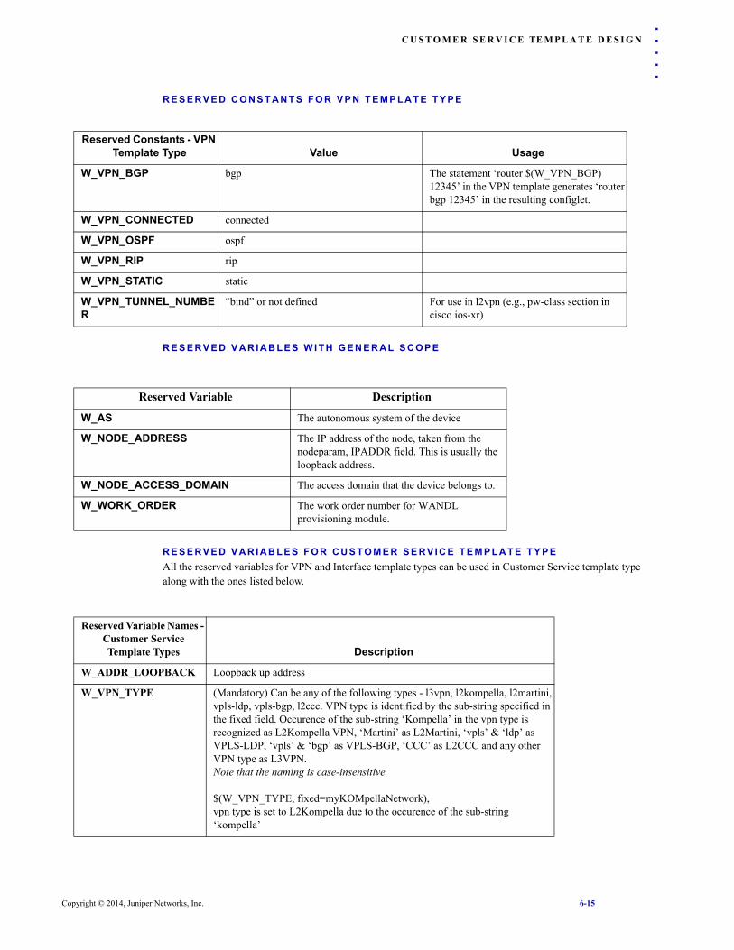
C U S T O M E R S E R V I C E TE M P L A T E D E S I G N
. . . . .
R E S E R V E D C O N S T A N T S F O R V P N T E M P L A T E T Y P ER E S E R V E D V A R I A B L E S W I T H G E N E R A L S C O P E
R E S E R V E D V A R I A B L E S F O R C U S T O M E R S E R V I C E T E M P L A T E T Y P EAll the reserved variables for VPN and Interface template types can be used in Customer Service template type along with the ones listed below.
Reserved Constants - VPN Template Type Value Usage
W_VPN_BGP bgp The statement ‘router $(W_VPN_BGP) 12345’ in the VPN template generates ‘router bgp 12345’ in the resulting configlet.
W_VPN_CONNECTED connected
W_VPN_OSPF ospf
W_VPN_RIP rip
W_VPN_STATIC static
W_VPN_TUNNEL_NUMBER
“bind” or not defined For use in l2vpn (e.g., pw-class section in cisco ios-xr)
Reserved Variable Description
W_AS The autonomous system of the device
W_NODE_ADDRESS The IP address of the node, taken from the nodeparam, IPADDR field. This is usually the loopback address.
W_NODE_ACCESS_DOMAIN The access domain that the device belongs to.
W_WORK_ORDER The work order number for WANDL provisioning module.
Reserved Variable Names - Customer Service Template Types Description
W_ADDR_LOOPBACK Loopback up address
W_VPN_TYPE (Mandatory) Can be any of the following types - l3vpn, l2kompella, l2martini, vpls-ldp, vpls-bgp, l2ccc. VPN type is identified by the sub-string specified in the fixed field. Occurence of the sub-string ‘Kompella’ in the vpn type is recognized as L2Kompella VPN, ‘Martini’ as L2Martini, ‘vpls’ & ‘ldp’ as VPLS-LDP, ‘vpls’ & ‘bgp’ as VPLS-BGP, ‘CCC’ as L2CCC and any other VPN type as L3VPN.Note that the naming is case-insensitive.
$(W_VPN_TYPE, fixed=myKOMpellaNetwork),vpn type is set to L2Kompella due to the occurence of the sub-string ‘kompella’
Copyright © 2014, Juniper Networks, Inc. 6-15

C U S T O M E R S E R V I C E TE M P L A T E D E S I G N6
R E S E R V E D T E M P L A T E V A R I A B L E S F O R C U S T O M E R S E R V I C E T E M P L A T E T Y P EVPN Template Candidates, instances of VPN templates, and Interface Model templates can be embed in the Customer Service template type using below listed reserved template variables
.
Reserved Template Variable - Customer
Service Template Type Description
W_CE_TEMPLATE Represents a CE interface facing UPE of template type Interface. Can be deployed only in VLAN block. In the Add Customer Service (2/5) GUI, this represents User Facing CE > PE Interface drop-down menu.Usage1: $(W_CE_TEMPLATE) lists all the interface templates in the User Facing CE > PE Interface drop-down menu.Usage2: $(W_CE_TEMPLATE, default=provisionproject:intftemplate)assigns the interface template, intftemplate to CE interface facing UPE by default.User can choose a different interface template from the drop-down, where provisionproject designates the project directory name, e.g., “sample” would represent the templates under /u/wandl/data/templates/sample.Usage3: $(W_CE_TEMPLATE, fixed=intftemplate)assigns the interface template, intftemplate to CE interface facing UPE by default. This interface template assigment cannot be changed later in the Customer Service GUI
W_NCE_TEMPLATE Represents an NCE interface facing NPE of template type Interface. Can be deployed only in VLAN block. In the Add Customer Service (2/5) GUI, this represents Network Facing CE > PE Interface drop-down menu.Usage: similar to W_CE_TEMPLATE
W_NPE_TEMPLATE Represents an NCE interface facing NPE of template type Interface. Can be deployed only in VLAN block. In the Add Customer Service (2/5) GUI, this represents Network Facing PE > CE Interface drop-down menuUsage: similar to W_CE_TEMPLATE.
W_UPE_TEMPLATE Represents a UPE interface facing CE of interface template type. Can be deployed only in VPN block. In the Add Customer Service (2/5) GUI, this represents User Facing PE > CE Interface drop-down menu.Usage: similar to W_CE_TEMPLATE
W_VPN_TEMPLATE Represents a VPN template type. Can be deployed only in VPN block.In the Customer Service (2/5) GUI, this represents VPN template drop-down menu.Usage1: $(W_VPN_TEMPLATE)lists all the template candidates of VPN type in the customer service GUI in VPN template drop-down menu.Usage2: $(W_VPN_TEMPLATE, default=provisionproject:vpn_inst)assigns the template candidate, vpn_inst, from project directory provisionproject (under /u/wandl/data/templates) to the vpn template by default. User can choose a different template candidate from the Customer Service GUI.Usage3: $(W_VPN_TEMPLATE, fixed=vpn_inst)assigns the template candidate, vpn_inst to the vpn template. This template candidate assigment cannot be changed later in the Customer Service GUI.
W_VLAN_TEMPLATE Represents a VLAN template type. Can be deployed only in VLAN block. In the Add Customer Service (2/5) GUI, this represents the VLAN template drop-down menu.Usage: similar to W_VPN_TEMPLATE
6-16 Copyright © 2014, Juniper Networks, Inc.

C U S T O M E R S E R V I C E TE M P L A T E D E S I G N
. . . . .
R E S E R V E D K E Y W O R D S F O R C U S T O M E R S E R V I C E T E M P L A T EReserved Keywords - Customer Service
Template Description Usage
@include block-type (Mandatory) Indicates the beginning of a block. The scope of the variables defined withing @include and @end include is local to the block.
@include VPNInherits all VPN template reserved variables. In the Add Customer Service (2/5) this block is the reason for the display of the display of VPN parameters panel & Network Facing PE > CE Interface drop-down menu.
@include VLANInherits all vlan template reserved variables. In the Add Customer Service (2/5)GUI, VLAN block type is the reason for the display of Access Parameters block, Network Facing CE > PE interface, User Facing PE > CE Interface and User Facing CE > PE Interface drop-down menu.
@end include (Mandatory) Indicates the end of the block
# (Optional) Indicates the beginning and end of comments. Comments can be written only at the beginning of the template.
#This is a comment field.#
[$(variable-name)+n] (Optional) Performs positive integer increment operation on a variable. The arithematic operation should be specified within ‘[‘ and ‘]’
[$(VAR)+2]increments the variable, VAR by 2
[$(variable-name)-n] (Optional) Performs positive integer decrement operation on a variable. The arithematic operation should be specified within ‘[‘ and ‘]’
[$(VAR)-3]decrements the variable, VAR by 3
{[n1-n2]} (Optional) Used to specify an integer range to the variable. The range is specified within ‘{[‘ and ‘]}’
$(VAR,{[100-500]})any value between 100 and 500 can be assigned to the variable, VAR.
$(variable-name)[a,b] Extract a substring from variable from position a to b-1.
$(variable-name)[,b] Extract a substring from variable from position 0 to b-1
$(variable-name)[a,] Extract a substring from variable from a
default (optional) When used with a variable, sets a default value to a variable. This value can be edited from the Add Customer Service GUI.
When used with a template variable, assigns a default template candidate to the reserved template variable. This assignment can later be changed from the Add Customer Service GUI.
$(VAR, default=abcd)sets VAR to abcd which can be edited from the customer service GUI.
$(W_VLAN_TEMPLATE, default=vlan_inst)assigns a template candidate, vlan_inst, to W_VLAN_TEMPLATE by default.
Copyright © 2014, Juniper Networks, Inc. 6-17

C U S T O M E R S E R V I C E TE M P L A T E D E S I G N6
fixed (Optional) When used with a variable, sets a variable to the specified value. This value cannot be changed later from the Customer Service GUI.
When used with template variables, assgins a template candidate (for VLAN & VPN template types)/model template (for interface template type) to reserved template type. This assignment cannot be changed later in the Customer Service GUI.
$(VAR, fixed=123)sets the variable,VAR value to 123
$(W_NCE_TEMPLATE, fixed=nCE_intf)assigns a model template, nCE_intf, to W_NCE_TEMPLATE.
format (Optional) Used to specify the format for a variableThree types of formats can be specified:FORMAT1:format=%xnd‘d’ represents integer format, ‘n’ represents number of digits, ‘x’ represents the digit to precede the number with to make it an n digit number.
FORMAT2:format=field1field2concatenates field1 and field2fields1&2 can be variables, integers or strings or special characters except ‘)’ ‘$’’{‘’}’’,’ as they have special meaning in template language
FORMAT3:format=field1field2field3fields 1,2&3can be variables, integers, strings or special characters except the keywords ‘)’’$’’{‘’}’’,’ as they have special meaning in template language. These keywords can be inlcuded by specifying them within double quotes.
FORMAT4:format=[$(VAR)-n1]”,”[$(VAR)+n2]n1,n2 can be any positive integers, increment (+) and decrement (-) operations should be specified within ‘[‘ and ‘]’ as shown above. If the format has any reserved symbols ‘)’’$’’{‘’}’’,’ then they should be specified withing double quotes as they have special meaning without quotes.
FORMAT1:$(VAR,format=%14d)assigning 36 to VAR, saves the variable as 1136.
FORMAT2:$(VAR,format=$(VAR1)45)if VAR1=123, thenVAR=12345
FORMAT3:$(VAR,format=$(VAR1):$(VAR2))if VAR1=12345VAR2=abcd, thenVAR=12345:abcd
FORMAT4:$(VAR,format=[$(VAR1)+12]”,”[$(var2)-45]if VAR1=40VAR2=50, then VAR=52,5
label (Optional) Indicates the variable-name specified is displayed in customer service GUI. Note that reserved variables W_RD, W_iRT, W_eRT, W_VRF_NAME have reserved labels and so labeling these variables overrides the reserved labels.
$(VAR,label=AS_NUMBER)VAR is displayed as AS_NUMBER in the Customer Service GUI.
Reserved Keywords - Customer Service
Template Description Usage
6-18 Copyright © 2014, Juniper Networks, Inc.

C U S T O M E R S E R V I C E TE M P L A T E D E S I G N
. . . . .
R E S E R V E D K E Y W O R D S F O R N O N - C U S T O M E R S E R V I C E S Y S T E M T E M P L A T E SReserved Keywords - Non-Customer Service System
Template types Description Usage
@section $(W_...) Indicates the beginning of a loop.The scope of the variables defined within @section and @end section is confined to the section.Make sure that the keyword starts at the beginning of a new line without any spaces preceding it.
@section neighbor_ipaddresses
@end section Indicates the end of a loop.Make sure that the keyword starts at the beginning of a new line without any spaces preceding it.
{...|...} Beginning and closing braces indicate a drop-down menu, with the menu items seperated by pipe. This drop-down menu appears in Add/Modify Templates Candiated window.
$(VAR, {abc|def|ghi})the VAR field appears as a drop-down menu with menu items abc,def,ghi in Add/Modify Template Candidate.
If Condition@if@else if@else@end if
The if condition can be used to activate a different set of router statements depending upon the value of a variable or a user selection.
Regular expressions are also supported.See an example at right.
@if $(W_VPN_INTF_NAME) == lo.* description This is a loopback;@else
description This is not a loopback;@endif
Copyright © 2014, Juniper Networks, Inc. 6-19

C U S T O M E R S E R V I C E TE M P L A T E D E S I G N6
6-20 Copyright © 2014, Juniper Networks, Inc.

. . . . .
. . . . . . . . . . . . . . . . . . . . . . . . . . . . . . . . . . .BASELINE PROVISIONING 7
he Baseline Provisioning module allows for template-based provisioning. One user designs the templates and another user can fill in the values for these variables.
Prerequis i tesPrior to beginning this task, you must have a live network or a network model created from config files in your network. You should also have connectivity to your router network. See the Getting Started Guide for instructions to get connected to your router network.
Related Documentat ionFor an overview of IP/MPLSView or for a detailed description of each IP/MPLSView feature and the use of each IP/MPLSView window, refer to the Design & Planning Guide, General Reference Guide, or Router User Guide.
For information on customer service provisioning, refer to Chapter 5, Customer Service Provisioning.
Out l ine1. Template-Based Provisioning Orders on page 7-1
2. Device Configuration on page 7-1
Deta i led Procedures
Template-Based Provis ioning OrdersCLI commands can be created by defining templates, applying the templates to selected routers, filling in the values for variables in the templates, and then generating the corresponding provisioning work order and CLI statements. Before jumping into template design, it is helpful to see the end result, as it will appear to the network operator, first. The following section describes the use of the Device Config menu to create forms based on simple templates. For more advanced templates for VPN, refer to Chapter 5, Customer Service Provisioning.
D E V I C E C O N F I G U R A T I O NOnce the device config templates have been designed, service categories created can be used to generate a form to fill in the missing variables needed to generate a configlet. The user chooses the routers to create configlets for and enters in the necessary values to create a provisioning order.
1. Select Provision > Device Config.
T
Copyright © 2014, Juniper Networks, Inc. 7-1

B A S E L I N E P R O V I S I O N I N G7
Figure 7-1 Service Selection
2. Select a service and click Next.
Figure 7-2 Device Selection
3. Select the devices to configure from the left hand side and click Add. Then Click Next.
4. If there are multiple templates defined for a selected service category and vendor OS, you may be prompted with the Multiple Templates window with a selection of which template you want to use per vendor. To allow the program to decide based on the best match for hardware and OS version, select “Auto Select”.
Figure 7-3 Multiple Templates
5. Following this, a form will be displayed corresponding to the variables in the device config template.
7-2 Copyright © 2014, Juniper Networks, Inc.

B A S E L I N E P R O V I S I O N I N G
. . . . .
Figure 7-4 Device Configuration Values
6. Fill out the values for the variables. Note that this window may be divided into several sections:
• Common Properties across all routers
• Vendor/OS Specific Properties for Junos and CiscoIOS. These are variables that show up only in the folder for one vendor, but not in the other.
• If there were Device Specific Properties indicated using ‘*’ in the provisioning template, there will be one tab per device to enter in the device-specific properties.
7. Click the Preview... button to preview your configlet before creating the new order.
8. Click the “Refresh” button in case the template has been modified after the template has already been chosen for the Device Config window.
9. Select New Order to create a provisioning order, or Generate to create the CLI configlets without creating a provisioning order. In the directory in which the configlets are generated, a CSV file is also generated remembering the values entered in for the order. These values can be modified and re-imported in the first page of the Device Config window through the Import button for a subsequent use of the Device Config wizard.
10. If there are variables that have not been filled in, you may get a warning message and have a choice wheter to continue or not. Click No. Then click the Preview button to see which variables have not been specified. The lines that cannot be provisioned due to incomplete specifications will be marked with a hash “#” symbol at the beginning of the line.
11. Once the order is successfully created, it must be authorized and activated to deploy it to the router. For more information, see Activating an Order on page 3-1
Copyright © 2014, Juniper Networks, Inc. 7-3

B A S E L I N E P R O V I S I O N I N G7
7-4 Copyright © 2014, Juniper Networks, Inc.

. . . . .
. . . . . . . . . . . . . . . . . . . . . . . . . . . . . . . . . . .BASELINE PROVISIONING TEMPLATE DESIGN 8
he Baseline Provisioning module allows for template-based provisioning. One user designs the templates and another user can fill in the values for these variables.
Prerequis i tesPrior to beginning this task, you must have a live network or a network model created from config files in your network. You should also have connectivity to your router network. See the Getting Started Guide for instructions to get connected to your router network.
Related Documentat ionFor an overview of IP/MPLSView or for a detailed description of each IP/MPLSView feature and the use of each IP/MPLSView window, refer to the Design & Planning Guide, General Reference Guide, or Router User Guide.
For information on customer service provisioning, refer to Chapter 5, Customer Service Provisioning.
Out l ine1. Designing Device Config Templates on page 8-1
2. Creating New Device Config Templates on page 8-2
3. Configlet Template Syntax on page 8-4
4. Creating a Configlet Group on page 8-8
5. Template Directory Organization on page 8-10
Deta i led Procedures
D E S I G N I N G D E V I C E C O N F I G T E M P L A T E S1. To open the Configuration Templates window from which templates can be written, select Setup >
Template Design. After the templates are ready, they can be run from Provision > Device Config.
2. The default project that will be open the first time is the sample project. The current project will be indicated in the window’s title, “Template Design (sample)”.
3. The sample templates are by default read-only. To create a copy that can be edited, select File > Open File Manager. Navigate to the directory /u/wandl/data/templates. Right-click the folder “sample” and select Copy. Then right-click in the empty space of the File Manager and click Paste. Right-click the newly created directory Copy_1_of_sample, and select Rename. Then rename the directory to the project name of your choice, e.g., sample2.
4. To change the project, select Action > Change Template Directory and choose your new project directory, e.g., sample2 for the Provisioning Template Directory. This option is also available from Tools > Options > General, Provisioning options pane.
5. The Configuration Templates window will be subdivided into 4 different categories of templates, of which this chapter focuses only on the first:
• Device Configlet Templates are generic templates that can be provisioned through Provision > Device Config.
T
Copyright © 2014, Juniper Networks, Inc. 8-1

B A S E L I N E P R O V I S I O N I N G TE M P L A T E D E S I G N8
• Config Management Templates used for config backup and restore in the Config/OS Management module. For more information, refer to the Management & Monitoring Guide.
• OS Management Templates used for router upgrade/downgrade in the Config/OS Management module. For more information, refer to the Management & Monitoring Guide.
• Service Templates deployed for end-to-end provisioning associated with the Customer Service window. Refer to Chapter 5, Customer Service Provisioning for more details.
Figure 8-1 Configuration Template
6. The Device Config Templates directory contains a list of folders where each one corresponds to a particular service category. Expand the folder (by double-clicking the name or clicking the hinge to the left of the service folder) to view the supported operating systems (e.g., CiscoIOS or Junos). Then expand the CiscoIOS or Junos folder to view the associated configlets for the service. When provisioning is done on a set of devices with different vendors, the program will automatically select the template underneath the appropriate vendor directory.
7. Click on a template on the left hand side and select “Edit” to view/edit a template. Note that the sample template project is read-only, in which case the “Edit” button will not be enabled. A read-write copy of the sample directory can be created as described in step 3 on page 8-1..
C R E A T I N G N E W D E V I C E C O N F I G T E M P L A T E S8. To add a configlet for a new service, right-click over Device Config Templates and select New >
Configlet... In the dialog box, enter in a Template Name, Description, and Service Category. The description here is for the specific template, and not for the service category containing this template.
8-2 Copyright © 2014, Juniper Networks, Inc.

B A S E L I N E P R O V I S I O N I N G TE M P L A T E D E S I G N
. . . . .
Figure 8-2 New Configlet Template
9. To add a configlet for a different vendor for the same service category, repeat the process but select a different Vendor/OS. The template name can be the same or different.
10. For a service category, the overall template selection criteria is as follows, from highest match to lowest:
• Vendor, OS Version and Hardware all match
• Vendor and OS Version match, no Hardware specified in the template
• Vendor and Hardware match, no OS Version specified in the template
• Vendor matches, no OS Version or Hardware specified in the template
• Matches a generic Vendor template, OS Version and Hardware not considered
11. The following symbols can be used for the OS Version : <, >, <=, >=, -
• Match exactly a number: 12.1
• Match a range inclusive: 12.1-13.2
• Match less/greater than (equal to) a number: “<12.1”
• The OS version only matches the format N.M where N and M are integers
• OS version comparisons are done as comparisons on the combination of two integers N and M, not the real number N.M, thus 5.9 < 5.12 < 6.0
12. To add a description for the service category, right-click over the service category, e.g., MyServiceCategory, and enter in a Description. This description will be displayed next to each service category when entering the Device Config window, to help the user decide which service category to provision.
Figure 8-3 Service Category Description
13. Select the new template from the left pane of the Template Design window to edit it. You can directly edit in the right pane or copy/paste text into the right pane. Right-click over the right pane to access Cut/Copy/Paste operations as well as Find/Replace, Select All, Show Line Number and Auto Format.
Copyright © 2014, Juniper Networks, Inc. 8-3

B A S E L I N E P R O V I S I O N I N G TE M P L A T E D E S I G N8
14. The template can take one of two formats: configlet or CLI, as shown in the next section. For options that should be entered by the user, variables can be put into the configlet or CLI statements.
15. Check your template’s syntax via Actions > Check Syntax.
16. Click the Save icon when you are finished making the edits. You can delete a configlet by right-clicking it and selecting Remove.
C O N F I G L E T T E M P L A T E S Y N T A X17. There are two alternative formats that can be used for the configlet template: Configlet or CLI. Below is an
example of a template for an interface configlet in JUNOS.
Configlet Format:interface $(name, {ge-[0-3]/[0-1]/[0-3]}){ description $(DESC, interface description) $(IP); vlan-tagging; encapsulation $(^ENCAP, {vlan-ccc|vlan-vpls}); unit $(UNIT-ID){ vlan-id $(VLAN-ID); family inet { address $(IP, {10.1.[10|20|30].[1-255]})/$(MASK, Enter mask); } family iso; family mpls; }
CLI Format:set interface $(name, {ge-[0-3]/[0-1]/[0-3]}) $(DESC, interface description) $(IP)set interface $(name) vlan-taggingset interface $(name) encapsulation $(^ENCAP, {vlan-ccc|vlan-vpls})set interface $(name) unit $(UNIT-ID) vlan-id $(VLAN-ID)set interface $(name) unit $(UNIT-ID) family inet address $(IP, {10.1.[10|20|30].[1-255]})/$(MASK, Enter mask)set interface $(name) unit $(UNIT-ID) family isoset interface $(name) unit $(UNIT-ID) family mpls
Category/Syntax Description Examples
Variables$(variable)or$([^|*]variable[,misc]*)
Notice that the variables that need to be user-defined are indicated in parentheses after the ‘$’ symbol. A variable is represented either as a textbox or drop-down box, depending upon syntax rules.The comma-separated misc section can include (a) the keyword “optional” or “required”(b) an optional field description, (c) syntax rules for validity checking, (d) a fixed value for the variable, or (e) a default value which can be edited.Note that the same variable can be specified in more than one place. In the example above, the $(IP) variable is specified in both the address and description lines.
$(Description, interface description)
$(Description, fixed=my description)”
$(Description, default=default to modify)”
$(Description, optional, an optional description field)
8-4 Copyright © 2014, Juniper Networks, Inc.

B A S E L I N E P R O V I S I O N I N G TE M P L A T E D E S I G N
. . . . .
optional This keyword sets the user variable as optional. If no input value is entered during provisioning, the user variable is not generated in the configlet.
$(Description, optional)
If no input is specified, user variable Description will not be generated in the configlet.
optionalpair This keyword sets the user variable and the command before the user variable as optional. If no input value is entered during provisioning, both the user variable and the command before the user variable are not generated in the configlet.
ip sla 77path-jitter 10.10.10.1 num-packets $(PacketNum, {[1-60000]}, optionalpair)
If no input is specified, the command “num-packets” and user variable PacketNum will not be generated in the configlet.
Device-Specific Properties*
The ‘*’ symbol indicates a variable (or section) that is device-specific. A tab will be generated in the Device Configuration window for each relevant device so that users can enter in different values for each device. For example, this could be applied to a loopback IP address.
$(*ip)
Multiple Options{x|y}
The ‘|’ symbol is used within braces to specify multiple options for a drop-down box. In the example at right, the possible encapsulations are vlan-ccc or vlan-vpls.
$(^ENCAP, {vlan-ccc|vlan-vpls});
Validity Checking{ }
The ‘{‘ and ‘}’ braces are used to enclose an expression for which validity checking should be performed. In the case of the statement to the right, validity checking will be performed to ensure the IP address matches the regular expression .
$(^ENCAP, {vlan-ccc|vlan-vpls});
address $(IP, {10.1.[10|20|30].[1-255]})/$(MASK, Enter mask);
Range Specification [ ]
The ‘[‘ and ‘]’ brackets can be specified within braces to specify a numerical range of values for validity checking. For example, ‘[1-255]’ is used to specify a range of permissible values from 1 to 255. ‘[10|20|30]’ indicates that the values 10, 20, or 30 are permissible. Note that contiguous range specifications should be separated by a delimiter character such as “.” that is not included within the range itself.
$(IP, {10.1.[10|20|30].[1-255]})
Section@section name,description@end section
Creates a repeatable section such that users can enter multiple values. Non-varying variables within the repeating section should be prefixed with the ‘^’ symbol. Use ‘*’ in front of the section name if the section is device-specific.
targets {@section targets, SNMP target${ipaddr, host receiving traps}@end section}
Category/Syntax Description Examples
Copyright © 2014, Juniper Networks, Inc. 8-5

B A S E L I N E P R O V I S I O N I N G TE M P L A T E D E S I G N8
Loop@loop variable [range]@end loop
Loops the specified variable through the values specified in the range.
@loop UNIT [101-199]interface Ethernet0/1.$(UNIT)encapsulation dot1Q $(UNIT)
!@end loop
If Condition@if@else if@else@end if
The if condition currently supports user-input variables from a select menu of multiple options {x|y}. Depending upon users’ selections, different statements will be printed. For example, the if condition can be used to activate a different set of router statements depending upon which PE-CE protocol the user decides to configure for a Layer 3 VPN.
@if $(protocol,{ospf|ebgp|rip| static|connected}, PE-CE protocol) == ospf<statements>
@else if $(protocol) == connected
<statements>@end if
@if $(trap,{yes|no},configure trap?) == yes
<statements>@else
<statements>@end if
Run CLI@include CLI@end include
Creates a block for user defined commands that can be run through the device CLI. The format is (Block Description, CLI command). Multiple CLI commands can be defined and the Device Config will allow you to select the commands(s) to run. This function can be used to verify configuration settings prior to provisioning.
@include CLIShow existing SNMP hosts, show snmp hostShow Version, show ver@end include
Global to Configlet Group^
The ‘^’ symbol indicates a property that is global, i.e., its value will be applied for all configlets in a configlet group with this property.
$(^ENCAP)
$(variable-name+number) Add number to the value of the variable. $(mtu+100)
$(variable-name)[0,3] Substring, e.g., i.e., substring that has 3 characters from the first position
Category/Syntax Description Examples
8-6 Copyright © 2014, Juniper Networks, Inc.

B A S E L I N E P R O V I S I O N I N G TE M P L A T E D E S I G N
. . . . .
refer=reserved_var,include=string,exclude=string,
Provides a select menu to list objects of a given type. For example, “refer=W_INTF_NAME” in the example at right will give the user a selection of interfaces to choose from corresponding to the selected node. The expression “exclude=Tunnel*” is used to filter out tunnel interfaces for Cisco, and the expression “include=ge*” can be used to display only ge* interfaces for Juniper.
Filtering Note: For different include/exclude rules, different variable names must be used. Thus, in the example at right, Cisco and Juniper interface templates must use different variable names for the interface, e.g., INTF_NAME_CISCO and INTF_NAME_JUNIPER.
More keywords: W_INTF_NAME: List interfaces for selected nodeW_INTF_ADDRESS: List IP addresses for selected nodes.W_NEIGHBOR_IP: List available IP addresses configured on neighboring nodes. These neighboring nodes are all other nodes in the Device Config besides the given node.See Appendix - WANDL Reserved Variables on page 8-10 for more keywords.
Cisco interface:interface $(*INTF_NAME_CISCO, refer=W_INTF_NAME, exclude=Tunnel*)
Juniper interface:interface $(*INTF_NAME_JUNIPER, refer=W_INTF_NAME, include=ge*)
$(*LOCAL_IP, refer=W_INTF_ADDRESS, include=lo*)
$(*NEIGHBOR_IP, refer=W_NEIGHBOR_IP, include=lo*)
Category/Syntax Description Examples
Copyright © 2014, Juniper Networks, Inc. 8-7

B A S E L I N E P R O V I S I O N I N G TE M P L A T E D E S I G N8
C R E A T I N G A C O N F I G L E T G R O U P18. A configlet group is an ordered group of configlet templates. Right-click over the Device Config Templates
and select New > Configlet Group. Choose a pre-existing service category and enter in a template name for the configlet group. To edit the configlet group, select the configlet group and then click “Edit Group...” or right-click the configlet group and select “Edit”.
19. Drag and drop desired configlet templates from the same service category into the configlet group on the right pane, and use the up and down arrows to reorder them as desired. Note that when any individual configlet referenced in the configlet group is modified, it will automatically be updated in the configlet group. Note also that the same configlet template can be repeated more than one time in a configlet group.
Figure 8-4 Configlet Template Group
20. Click the Save icon to save your Configlet Group.
8-8 Copyright © 2014, Juniper Networks, Inc.

B A S E L I N E P R O V I S I O N I N G TE M P L A T E D E S I G N
. . . . .
A P P L Y I N G A T E M P L A T EIn the Template window, the Apply feature can be used to quickly verify your template without entering into the Device Config window. Note: This feature can be used for basic testing of the template. However, users are now recommended to use the Device Config window described in Chapter 7, Baseline Provisioning to create provisioning orders.21. After selecting a configlet template or configlet template group on the left hand side of the window, click the Apply button to generate CLI configlets based on the template. This will switch you to the “Apply Configuration Template” window. Note that you can switch back to the Configuration Templates definition window later by clicking the Cancel button, but you may want to save any changes to a file before doing so, by selecting Export Vars.
Figure 8-5 Applying a Template
22. In the upper left corner of the Apply Configlet Template window, right-click on the arrow to the right of Devices to filter for a particular router vendor or model. Select the checkboxes to the left of the routers for which the template should be applied.
23. For each of the checked routers, you may click on them individually from the upper right list and fill in the property values in the lower left hand side of the window for the selected router. In order to have a value be applied to all checked routers instead of just the selected one, add the suffix “/g” at the end of the value. As you fill in the values, they will be populated on the right hand pane in lieu of the corresponding variables. Any descriptions or syntax requirements will be shown in the bottom left corner of the window.
24. Note that the configlet template “MyInterface” that had been duplicated in the configlet group is now displayed in the variables list as “MyInterface.1” and “MyInterface.2”. Additionally, the global variable “ENCAP” that had been specified in the myinterface template using the ‘^’ symbol will have its value applied for all interfaces with the “ENCAP” property on the given router. In this case, the value is applied for both MyInterface.1 and MyInterface.2.
25. You can also import the property values from a file instead of entering them in the graphical interface. To create the appropriate file format, first click Export Vars..., and then specify a filename to export the variables to. Open up the file from the File Manager and fill in the necessary fields for each of the routers in the file. Then you may import the file using the Import Vars... button to fill in the values from the file.
26. When you are finished populating the fields, click Generate to create the corresponding CLI commands, and then select a directory for the new configlets. This will generate two files for each selected router, one with the suffix .template that indicates the template used for the router, and one with the suffix .cli to
Copyright © 2014, Juniper Networks, Inc. 8-9

B A S E L I N E P R O V I S I O N I N G TE M P L A T E D E S I G N8
indicate the actual CLI statements. Note that any value not filled in will still be printed in the CLI file, but as a variable, e.g., in the format “$(variable)”. These should be filled in or removed before provisioning.
Template Directory Organizat ion27. The expected format underneath the /u/wandl/data/templates/ directory is to find a template project
directory, followed by the template type (e.g., devicecfg for device config), followed by the service category, followed by a subdirectory for each router OS type using exact names, e.g., CiscoIOS, JUNOS, ERX, or Redback, followed by the template text file which can have any name.
For example, for setting up SNMP, we could have the following templates following the /u/wandl/data/templates/<template project name>/<template category>/<service category name>/<OS>/<template file> directory/file naming convention:
• /u/wandl/data/templates/sample2/devicecfg/SNMP/CiscoIOS/SNMP.txt
• /u/wandl/data/templates/sample2/devicecfg/SNMP/Junos/SNMP.txt
• /u/wandl/data/templates/sample2/devicecfg/SNMP/Redback/snmp.redback.txt
• /u/wandl/data/templates/sample2/devicecfg/SNMP/ERX/snmp.erx.txt
Appendix - WANDL Reserved Var iab les
W _ N E I G H B O R _ T U N N E LA subset of W_TUNNEL that list only tunnels terminated on selected nodes. For example if you choose two nodes: A and B, W_NEIGHBOR_TUNNEL will only list tunnel between A and B, instead of all tunnels configured on A or B. Example:
@section *Install_Route_to_LSPprotocols { mpls { label-switched-path $(LSP_NAME, refer=W_NEIGHBOR_TUNNEL, label switch path name) { no-install-to-address; install $(IP_ADDRESS, refer=W_NEIGHBOR_IP, include=lo0); } }}@end section
W _ V P NThis keyword is used to list all VPNs configured on a router. Example:
policy-options { policy-statement $(*VPN_NAME, refer=W_VPN)_EXPORT { term a { then { next-hop $(*IP_ADDRESS, refer=W_INTF_ADDRESS, exclude=lo0); } } }}
W _ T U N N E LThis keyword is used to list all tunnels configured on a router. Example:
@section *Install_Route_to_LSPprotocols { mpls { label-switched-path $(LSP_NAME, refer=W_TUNNEL, label switch path name) { no-install-to-address; install $(IP_ADDRESS, refer=W_NEIGHBOR_IP);
8-10 Copyright © 2014, Juniper Networks, Inc.

B A S E L I N E P R O V I S I O N I N G TE M P L A T E D E S I G N
. . . . .
} }}@end sectionW _ B G P _ P O L I C YThis keyword is used to list BGP policies configured on a router. Example:
router bgp $(*LOCAL_ASN, default=W_AS, Local AS Number) neighbor $(NEIGHBOR_IP, refer=W_NEIGHBOR_IP, Neighbor IP Address) route-map $(BGP_POLICY_IN, refer=W_BGP_POLICY, BGP Route Policy Input) in neighbor $(NEIGHBOR_IP, refer=W_NEIGHBOR_IP, Neighbor IP Address) route-map $(BGP_POLICY_OUT,refer=W_BGP_POLICY, BGP Route Policy Output) out
W _ I N T F _ P O L I C E RThis keyword is used to list rate limit policer configured on a router. Example:
interface $(INTF_NAME, refer=W_INTF_NAME, include=*) service-policy input $(POLICY_NAME_INPUT,refer=W_INTF_POLICER) service-policy output $(POLICY_NAME_OUTPUT,refer=W_INTF_POLICER)!
W _ I N T F _ N A M EThis keyword is used to list name of all interface configured on a node. Example:
router bgp $(*LOCAL_ASN, default=W_AS, Local AS Number) neighbor $(NEIGHBOR_IP, refer=W_NEIGHBOR_IP, Neighbor IP Address) update-source $(SOURCE_INTERFACE,refer=W_INTF_NAME, include*,Update Source Interface)!
W _ I N T F _ A D D R E S SThis keyword is used to list IPv4 address configured on local interface. Example:
protocols { bgp { group $(BGP_GROUP, BGP Group) { local-address $(SOURCE_INTERFACE,refer=W_INTF_ADDRESS, include*,Update Source Interface); } }}
W _ I N T F _ A D D R E S S _ I P V 6This keyword is used to list IPv6 address configured on local interface. Example:
protocols { bgp { group $(BGP_GROUP, BGP Group) { local-address $(SOURCE_INTERFACE, refer=W_INTF_ADDRESS_IPV6, Update Source Interface IPv6 Address); } }}
W _ N E I G H B O R _ I P V 6This keyword is used to list IPv6 address configured on remote router's interface. Example:router bgp $(*LOCAL_ASN, default=W_AS, Local AS Number) neighbor $(NEIGHBOR_IPV6, refer=W_NEIGHBOR_IPV6, Neighbor IPv6 Address) remote-as $(REMOTE_ASN, refer=W_AS, Remote AS Number)
Copyright © 2014, Juniper Networks, Inc. 8-11

B A S E L I N E P R O V I S I O N I N G TE M P L A T E D E S I G N8
!
W _ N E I G H B O R _ I PThis keyword is used to list IPv4 address configured on remote router's interface. Example:
router bgp $(*LOCAL_ASN, default=W_AS, Local AS Number) neighbor $(NEIGHBOR_IP, refer=W_NEIGHBOR_IP, Neighbor IP Address) remote-as $(REMOTE_ASN, refer=W_AS, Remote AS Number)!
W _ A SThis keyword is used to list AS number configured. You can use it either with “refer” or “default” keyword. The “default” keyword will initialize the variable with the local AS number, while the “refer” keyword will list all the AS numbers available in the network. Example:
router bgp $(*LOCAL_ASN, default=W_AS, Local AS Number) neighbor $(NEIGHBOR_IP, refer=W_NEIGHBOR_IP, Neighbor IP Address) remote-as $(REMOTE_ASN, refer=W_AS, Remote AS Number)!
W _ N O D E _ A D D R E S SThis keyword is used to represent router’s ID configured. You can use it either with “refer” or “default” keyword. The “default” keyword will initialize the variable with the local router’s ID, while the “refer” keyword will list all the router’s ID available in the network. Example:
protocols { bgp { group $(BGP_GROUP, BGP Group) { local-address $(SOURCE_INTERFACE, default=W_NODE_ADDRESS, Update Source Interface); } }}
W _ W O R K _ O R D E RThe work order number for WANDL provisioning module.
8-12 Copyright © 2014, Juniper Networks, Inc.