Embed Size (px)
Citation preview
Wandel & GoltermannCommunications Test Solutions

Visit our Web site for regular updates on our ISDN Test Solutions: http://isdn.wg.com
Table of Contents
3
ABOUT ISDN
ISDN Network Topology . . . . . . . . . . . . . . . . . . . . . . . . . . . . . . . . . . . . . . . . . . . . . . . . . . . . . . . . . . . . . . . . . . . . . . . . . . . . . . . . . . . . . . . . . . . . . . . . . . . . . . . . . . 4
ISDN Basics . . . . . . . . . . . . . . . . . . . . . . . . . . . . . . . . . . . . . . . . . . . . . . . . . . . . . . . . . . . . . . . . . . . . . . . . . . . . . . . . . . . . . . . . . . . . . . . . . . . . . . . . . . . . . . . . . . . . . . . . . . . . 5
ISDN MEASUREMENTS
Test of So bus/Cabling at Customer Premises . . . . . . . . . . . . . . . . . . . . . . . . . . . . . . . . . . . . . . . . . . . . . . . . . . . . . . . . . . . . . . . . . . . . . . . . . . 6
TE Simulation Mode . . . . . . . . . . . . . . . . . . . . . . . . . . . . . . . . . . . . . . . . . . . . . . . . . . . . . . . . . . . . . . . . . . . . . . . . . . . . . . . . . . . . . . . . . . . . . . . . . . . . . . . . . . . . . . . . 6
NT Simulation Mode . . . . . . . . . . . . . . . . . . . . . . . . . . . . . . . . . . . . . . . . . . . . . . . . . . . . . . . . . . . . . . . . . . . . . . . . . . . . . . . . . . . . . . . . . . . . . . . . . . . . . . . . . . . . . . . . 6
Bit Error Ratio Test (BERT) . . . . . . . . . . . . . . . . . . . . . . . . . . . . . . . . . . . . . . . . . . . . . . . . . . . . . . . . . . . . . . . . . . . . . . . . . . . . . . . . . . . . . . . . . . . . . . . . . . . . . . 6
Test of Bearer Services and Teleservices (BC, HLC, LLC) . . . . . . . . . . . . . . . . . . . . . . . . . . . . . . . . . . . . . . . . . . . . . . . . . . . . . . . . . 7
Supplementary Services Test . . . . . . . . . . . . . . . . . . . . . . . . . . . . . . . . . . . . . . . . . . . . . . . . . . . . . . . . . . . . . . . . . . . . . . . . . . . . . . . . . . . . . . . . . . . . . . . . . . . 7
X.25/D and X.25/B Test . . . . . . . . . . . . . . . . . . . . . . . . . . . . . . . . . . . . . . . . . . . . . . . . . . . . . . . . . . . . . . . . . . . . . . . . . . . . . . . . . . . . . . . . . . . . . . . . . . . . . . . . . . . 7
D-Channel Trace . . . . . . . . . . . . . . . . . . . . . . . . . . . . . . . . . . . . . . . . . . . . . . . . . . . . . . . . . . . . . . . . . . . . . . . . . . . . . . . . . . . . . . . . . . . . . . . . . . . . . . . . . . . . . . . . . . . . . 7
Monitoring . . . . . . . . . . . . . . . . . . . . . . . . . . . . . . . . . . . . . . . . . . . . . . . . . . . . . . . . . . . . . . . . . . . . . . . . . . . . . . . . . . . . . . . . . . . . . . . . . . . . . . . . . . . . . . . . . . . . . . . . . . . . . . 8
U Interface (BRA) . . . . . . . . . . . . . . . . . . . . . . . . . . . . . . . . . . . . . . . . . . . . . . . . . . . . . . . . . . . . . . . . . . . . . . . . . . . . . . . . . . . . . . . . . . . . . . . . . . . . . . . . . . . . . . . . . . . . 8
Equipment In Situ . . . . . . . . . . . . . . . . . . . . . . . . . . . . . . . . . . . . . . . . . . . . . . . . . . . . . . . . . . . . . . . . . . . . . . . . . . . . . . . . . . . . . . . . . . . . . . . . . . . . . . . . . . . . . . . . . . . . 9
APPLICATIONS
Cabling at Customer Premises . . . . . . . . . . . . . . . . . . . . . . . . . . . . . . . . . . . . . . . . . . . . . . . . . . . . . . . . . . . . . . . . . . . . . . . . . . . . . . . . . . . . . . . . . . . 10
ISDN BRA and PRA Installation . . . . . . . . . . . . . . . . . . . . . . . . . . . . . . . . . . . . . . . . . . . . . . . . . . . . . . . . . . . . . . . . . . . . . . . . . . . . . . . . . . . . . . . . . . . . 11
ISDN BRA and PRA Commissioning . . . . . . . . . . . . . . . . . . . . . . . . . . . . . . . . . . . . . . . . . . . . . . . . . . . . . . . . . . . . . . . . . . . . . . . . . . . . . . . . . . . . 12
ISDN BRA and PRA Maintenance . . . . . . . . . . . . . . . . . . . . . . . . . . . . . . . . . . . . . . . . . . . . . . . . . . . . . . . . . . . . . . . . . . . . . . . . . . . . . . . . . . . . . . . 13
ISDN Equipment Installation and Maintenance . . . . . . . . . . . . . . . . . . . . . . . . . . . . . . . . . . . . . . . . . . . . . . . . . . . . . . . . . . . . . . . . . . . 14
PRODUCT LITERATURE
List of available documentation . . . . . . . . . . . . . . . . . . . . . . . . . . . . . . . . . . . . . . . . . . . . . . . . . . . . . . . . . . . . . . . . . . . . . . . . . . . . . . . . . . . . . . . . . . 15
IBT-5, ISDN Tester for the Basic Rate Access . . . . . . . . . . . . . . . . . . . . . . . . . . . . . . . . . . . . . . . . . . . . . . . . . . . . . . . . . . . . . . . . . . . . . . . . . 16
IBT-10, ISDN Tester/Analyzer for the Basic Rate Access . . . . . . . . . . . . . . . . . . . . . . . . . . . . . . . . . . . . . . . . . . . . . . . . . . . . . . . . . 17
IBT-20, ISDN Tester/Analyzer for the Primary Rate Access . . . . . . . . . . . . . . . . . . . . . . . . . . . . . . . . . . . . . . . . . . . . . . . . . . . . . 18
IMK-30/-31/-32, ISDN Tester/Analyzer for the Basic and Primary Rate Accesses . . . . . . . . . . . . . . . . . . . . . . . . . 19
Windows™ PC Detailed Decoder, Real-Time Analysis Software . . . . . . . . . . . . . . . . . . . . . . . . . . . . . . . . . . . . . . . . . . . . . 20
IST-15, ISDN/LAN Cable Tester . . . . . . . . . . . . . . . . . . . . . . . . . . . . . . . . . . . . . . . . . . . . . . . . . . . . . . . . . . . . . . . . . . . . . . . . . . . . . . . . . . . . . . . . . . . . . . 21
IUM-10, ISDN U-Interface Monitor . . . . . . . . . . . . . . . . . . . . . . . . . . . . . . . . . . . . . . . . . . . . . . . . . . . . . . . . . . . . . . . . . . . . . . . . . . . . . . . . . . . . . . . . . 22
DA-5, Multiport Protocol Analyzer . . . . . . . . . . . . . . . . . . . . . . . . . . . . . . . . . . . . . . . . . . . . . . . . . . . . . . . . . . . . . . . . . . . . . . . . . . . . . . . . . . . . . . . . . 23
DominoWAN ISDN, ISDN Internetwork Analyzer . . . . . . . . . . . . . . . . . . . . . . . . . . . . . . . . . . . . . . . . . . . . . . . . . . . . . . . . . . . . . . . . . . . . 24
Examples of ISDN Collaterals . . . . . . . . . . . . . . . . . . . . . . . . . . . . . . . . . . . . . . . . . . . . . . . . . . . . . . . . . . . . . . . . . . . . . . . . . . . . . . . . . . . . . . . . . . . . 25
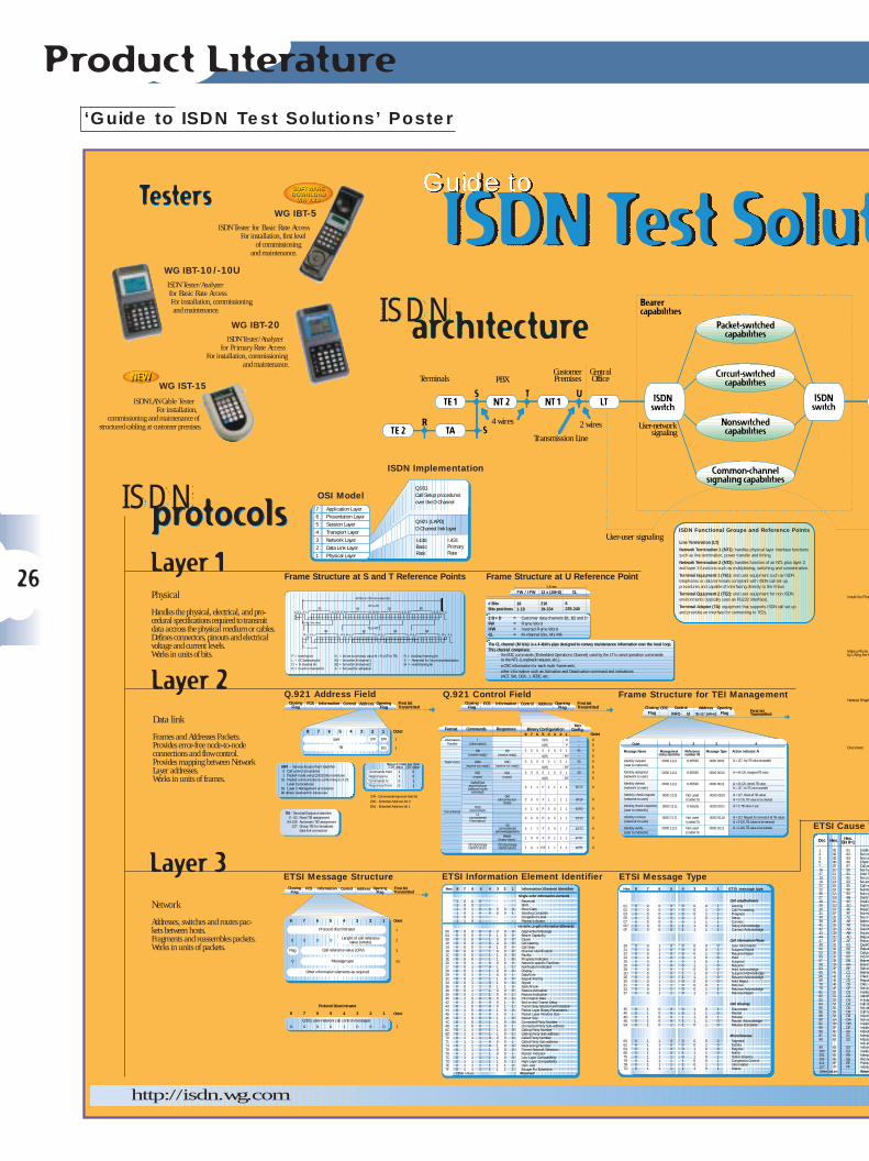
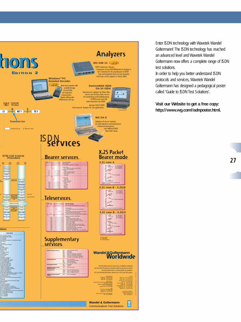
‘Guide to ISDN Test Solutions’ Poster . . . . . . . . . . . . . . . . . . . . . . . . . . . . . . . . . . . . . . . . . . . . . . . . . . . . . . . . . . . . . . . . . . . . . . . . . . . . . . . 26
4
Acronyms and definitions:
BC: Bearer CapabilityHLC: High Layer CompatibilityLLC: Low Layer CompatibilityTEI: Terminal End Point IdentifierSAPI: Service Access Point IdentifierNEBE: Near End Block ErrorFEBE: Far End Block ErrorPSDN: Public Switched Data Network
CustomerPremises
Transmission Line
Terminals PBX
2 wires4 wires
CentralOffice
TE 2 TA
TE 1 NT 2S
S
NT 1 LT ISDNswitch
User-networksignaling
T U
R
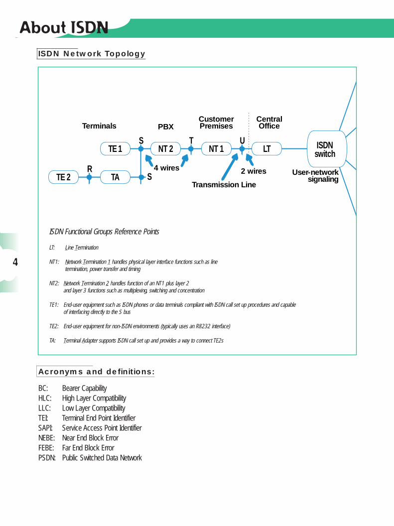
ISDN Functional Groups Reference Points
LT: Line Termination
NT1: Network Termination 1 handles physical layer interface functions such as linetermination, power transfer and timing
NT2: Network Termination 2 handles function of an NT1 plus layer 2and layer 3 functions such as multiplexing, switching and concentration
TE1: End-user equipment such as ISDN phones or data terminals compliant with ISDN call set up procedures and capable of interfacing directly to the S bus
TE2: End-user equipment for non-ISDN environments (typically uses an R8232 interface)
TA: Terminal Adapter supports ISDN call set up and provides a way to connect TE2s
ISDN Network Topology
About ISDN
LTNT1
SO
SO
TO U ISDN
5
About ISDN ISDN Basics
An end-user is connected to the local exchange over a twisted pair (the local loop). ISDN reuses this local loop to provide userswith digital communications. ISDN offers bearer services (speech, data), teleservices (phone, Fax G4) and some facilities calledSupplementary Services such as Call Forwarding, Three-way conference, Charging information, etc. In addition, ISDN offers a gateway to packet-switched data networks (X.25).
ISDN standards define the rules for this interface between the user and the network.Two different types of access interfaces are offered: the Basic Rate Access (BRA) and the Primary Rate Access (PRA).
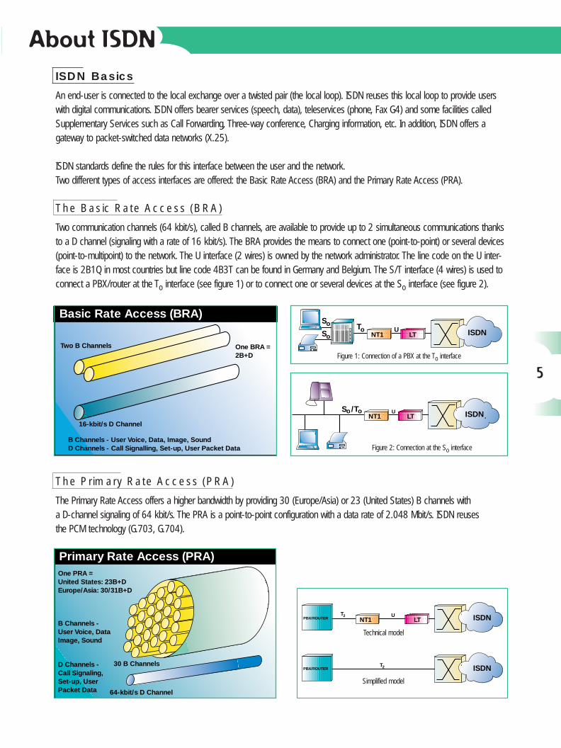
The Basic Rate Access (BRA)
Two communication channels (64 kbit/s), called B channels, are available to provide up to 2 simultaneous communications thanksto a D channel (signaling with a rate of 16 kbit/s). The BRA provides the means to connect one (point-to-point) or several devices(point-to-multipoint) to the network. The U interface (2 wires) is owned by the network administrator. The line code on the U inter-face is 2B1Q in most countries but line code 4B3T can be found in Germany and Belgium. The S/T interface (4 wires) is used toconnect a PBX/router at the To interface (see figure 1) or to connect one or several devices at the So interface (see figure 2).
The Primary Rate Access (PRA)
The Primary Rate Access offers a higher bandwidth by providing 30 (Europe/Asia) or 23 (United States) B channels with a D-channel signaling of 64 kbit/s. The PRA is a point-to-point configuration with a data rate of 2.048 Mbit/s. ISDN reuses the PCM technology (G.703, G.704).
Basic Rate Access (BRA)
Two B Channels
16-kbit/s D Channel
B Channels - User Voice, Data, Image, SoundD Channels - Call Signalling, Set-up, User Packet Data
One BRA =2B+D
LTNT1U ISDN
ToS oS o
LTNT1U ISDN
S /To o
One PRA =United States: 23B+DEurope/Asia: 30/31B+D
B Channels -User Voice, DataImage, Sound
D Channels -Call Signaling,Set-up, UserPacket Data 64-kbit/s D Channel
Primary Rate Access (PRA)
30 B Channels
PBX/ROUTER LTNT1U ISDN
PBX/ROUTER ISDNT2
T2
Figure 1: Connection of a PBX at the To interface
Figure 2: Connection at the So interface
Simplified model
Technical model
ISDN Measurements
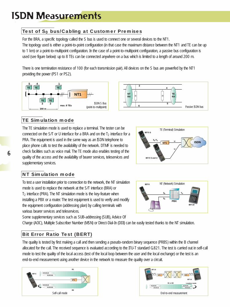
Test of S0 bus/Cabling at Customer Premises
For the BRA, a specific topology called the S bus is used to connect one or several devices to the NT1.The topology used is either a point-to-point configuration (in that case the maximum distance between the NT1 and TE can be upto 1 km) or a point-to-multipoint configuration. In the case of a point-to-multipoint configuration, a passive bus configuration isused (see figure below): up to 8 TEs can be connected anywhere on a bus which is limited to a length of around 200 m.
There is one termination resistance of 100 (for each transmission pair). All devices on the S bus are powerfed by the NT1 providing the power (PS1 or PS2).
TE Simulation mode
The TE simulation mode is used to replace a terminal. The tester can beconnected on the S/T or U interface for a BRA and on the T2 interface for aPRA. The equipment is used in the same way as an ISDN telephone toplace phone calls to test the availability of the network. DTMF is needed tocheck facilities such as voice mail. The TE mode also enables testing of thequality of the access and the availability of bearer services, teleservices andsupplementary services.
NT Simulation mode
To test a user installation prior to connection to the network, the NT simulationmode is used to replace the network at the S/T interface (BRA) or T2 interface (PRA). The NT simulation mode is the key-feature when installing a PBX or a router. The test equipment is used to verify and modifythe equipment configuration (addressing plan) by calling terminals withvarious bearer services and teleservices.Some supplementary services such as SUB-addressing (SUB), Advice OfCharge (AOC), Multiple Subscriber Number (MSN) or Direct-Dial-In (DDI) can be easily tested thanks to the NT simulation.
Bit Error Ratio Test (BERT)
The quality is tested by first making a call and then sending a pseudo-random binary sequence (PRBS) within the B channel allocated for the call. The received sequence is evaluated according to the ITU-T standard G.821. The test is carried out in self-callmode to test the quality of the local access (test of the local loop between the user and the local exchange) or the test is an end-to-end measurement using another device in the network to measure the quality over a circuit.
NT1
IBT-5 S and U
IBT-5 S
U
U
ISDNS /To o
PBX
IBT-5
IBT-10
S o T o
S o
IBT-5
10110110
01101101
10110110
01101101
NT1
B1
B2
IBT-10
Loopbox mode
IBT-10
B1 or B2
NT1 NT1
01101101
10110110
01101101
10110110
U US /To o S /To o
6
3
6
4
5
TERX
NTRX
Passive ISDN bus
TE (Terminal) Simulation
NT (Network) Simulation
NT1
TE TE TE
TE TE
200 m
max. 8 TEs3 2
145
ISDN S Bus(point-to-multipoint)
Self-call mode End-to-end measurement
R R
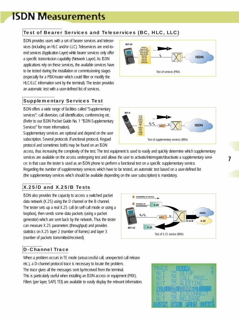
Test of Bearer Services and Teleservices (BC, HLC, LLC)
ISDN provides users with a set of bearer services and teleser-vices (including an HLC and/or LLC). Teleservices are end-to-end services (Application Layer) while bearer services only offera specific transmission capability (Network Layer). As ISDNapplications rely on these services, the available services haveto be tested during the installation or commissioning stages (especially for a PBX/router which could filter or modify theHLC/LLC information sent by the terminal). The tester provides an automatic test with a user-defined list of services.
Supplementary Services Test
ISDN offers a wide range of facilities called “Supplementaryservices”: call diversion, call identification, conferencing etc.(Refer to our ISDN Pocket Guide No. 1 “ISDN SupplementaryServices” for more information).Supplementary services are optional and depend on the usersubscription. Several protocols (Functional protocol, Keypadprotocol and sometimes both) may be found on an ISDNaccess, thus increasing the complexity of the test. The test equipment is used to easily and quickly determine which supplementaryservices are available on the access undergoing test and allows the user to activate/interrogate/deactivate a supplementary servi-ce: in that case the tester is used as an ISDN phone to perform a functional test on a specific supplementary service.Regarding the number of supplementary services which have to be tested, an automatic test based on a user-defined list (the supplementary services which should be available depending on the user subscription) is mandatory.
X.25/D and X.25/B Tests
ISDN also provides the capacity to access a switched packetdata network (X.25) using the D channel or the B channel.The tester sets up a real X.25 call (in self-call mode or using aloopbox), then sends some data packets (using a packetgenerator) which are sent back by the network. Thus the testercan measure X.25 parameters (throughput) and provides statistics on X.25 layer 2 (number of frames) and layer 3(number of packets transmitted/received).
D-Channel Trace
When a problem occurs in TE mode (unsuccessful call, unexpected call releaseetc.), a D-channel protocol trace is necessary to locate the problem.The trace gives all the messages sent by/received from the terminal.This is particularly useful when installing an ISDN access or equipment (PBX).Filters (per layer, SAPI, TEI) are available to easily display the relevant information.
ISDN Measurements
IBT-20
T ISDN
?…EDSS-1
Speech BCAudio 3.1 kHz
Data 64 BCData 56 BC
SpeechFax G3Fax G4Teletext
Videotext
2
Test of services (PRA)
IBT-5
U
?…CLIPCLIRCOLPCOLRSUBAOCTP
HOLDCFUCFB
CFNRCUG
NT1S /To o ISDN
Test of supplementary services (BRA)
IBT-10
NT1U
ISDN
X.25
X.25
X.25
Availability of service1
Integrity oftransmission
2
D or B
/ToSo
Test of X.25 service (BRA)
7
ISDN Measurements
8
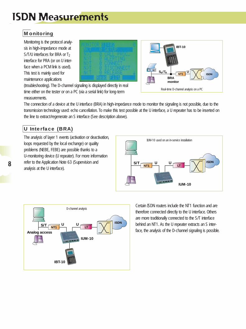
Monitoring
Monitoring is the protocol analy-sis in high-impedance mode atS/T/U interfaces for BRA or T2
interface for PRA (or on U inter-face when a PCM link is used).This test is mainly used formaintenance applications (troubleshooting). The D-channel signaling is displayed directly in realtime either on the tester or on a PC (via a serial link) for long-term measurements.The connection of a device at the U interface (BRA) in high-impedance mode to monitor the signaling is not possible, due to thetransmission technology used: echo cancellation. To make this test possible at the U interface, a U repeater has to be inserted onthe line to extract/regenerate an S interface (See description above).
U Interface (BRA)
The analysis of layer 1 events (activation or deactivation,loops requested by the local exchange) or quality problems (NEBE, FEBE) are possible thanks to a U-monitoring device (U repeater). For more informationrefer to the Application Note 63 (Supervision and analysis at the U interface).
Certain ISDN routers include the NT1 function and aretherefore connected directly to the U interface. Othersare more traditionally connected to the S/T interfacebehind an NT1. As the U repeater extracts an S inter-face, the analysis of the D-channel signaling is possible.
IBT-10
NT1U
BRAmonitor
S /To oISDN
IUM-10
LTNT1S/T UU ISDN
IUM-10
LTNT1
S/T UU
Analog access
IBT-10
ISDN
Real-time D-channel analysis on a PC
IUM-10 used on an in-service installation
D-channel analysis
9
ISDN Measurements
ISDN
LTNT1 U
IUM-10
IBT-10/-10US/T monitor
IBT-10/-10US/T monitor
IBT-10/-10UTE mode
IBT-5UTE modeIBT-5S/S+U
TE mode
IBT-5S/S+UNT mode
IBT-10/-10UTE mode
IBT-10/-10UNT mode
IST-15
Private/PublicNetwork
Local Loop
S /To o
Windows PC Detailed Decoder
TM
Windows PC Detailed Decoder
TM
ISDN
LTNT1 UT
IBT-20Monitor
IBT-20AutoTrack mode
IBT-20TE mode
IBT-20U/G.704 Monitor
IBT-20NT mode
DA-5
IBT-20HIZBERT mode
Private/PublicNetwork
2
WindowsPC Detailed Decoder
WindowsPC Detailed Decoder
TM
TM
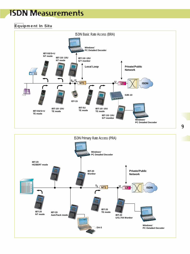
ISDN Primary Rate Access (PRA)
ISDN Basic Rate Access (BRA)
Equipment In Situ
Applications
10
Cabling at Customer Premises
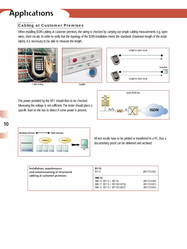
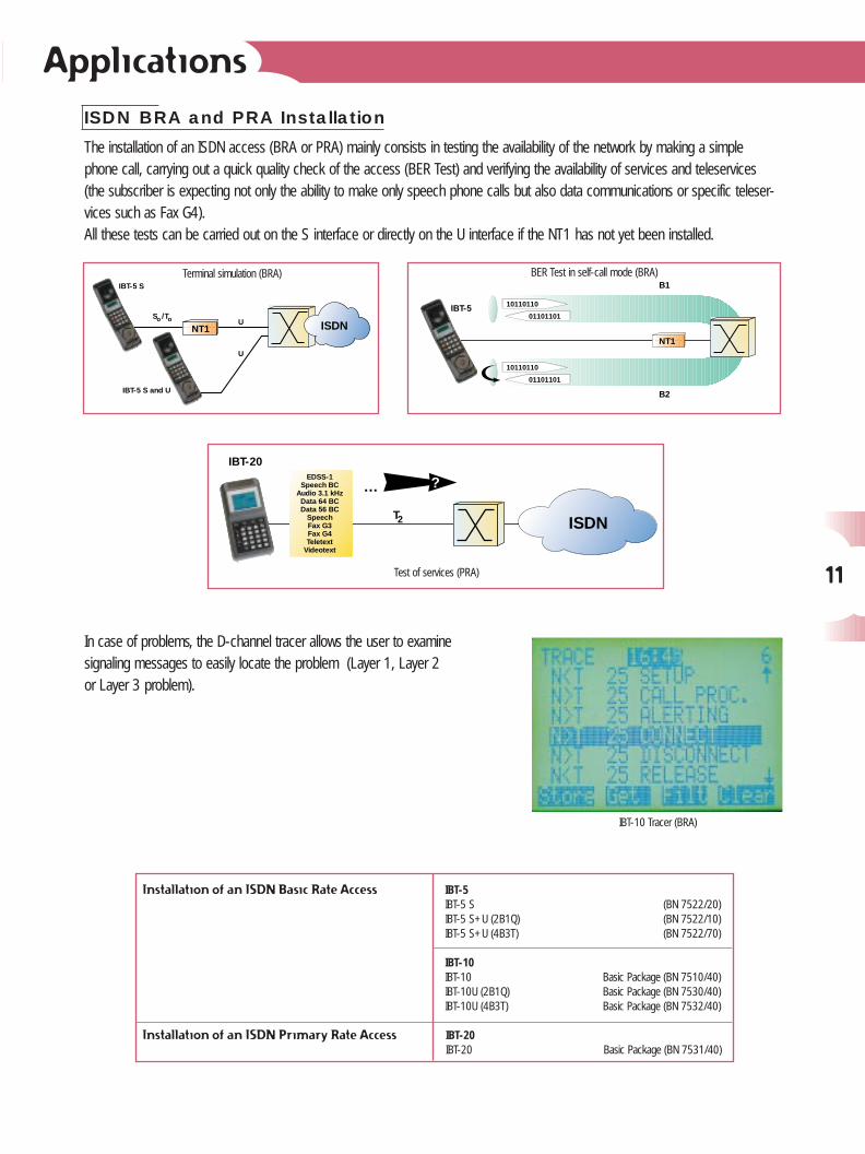
When installing ISDN cabling at customer premises, the wiring is checked by carrying out simple cabling measurements e.g. openwires, short circuits. In order to verify that the topology of the ISDN installation meets the standards (maximum length of the instal-lation), it is necessary to be able to measure the length.
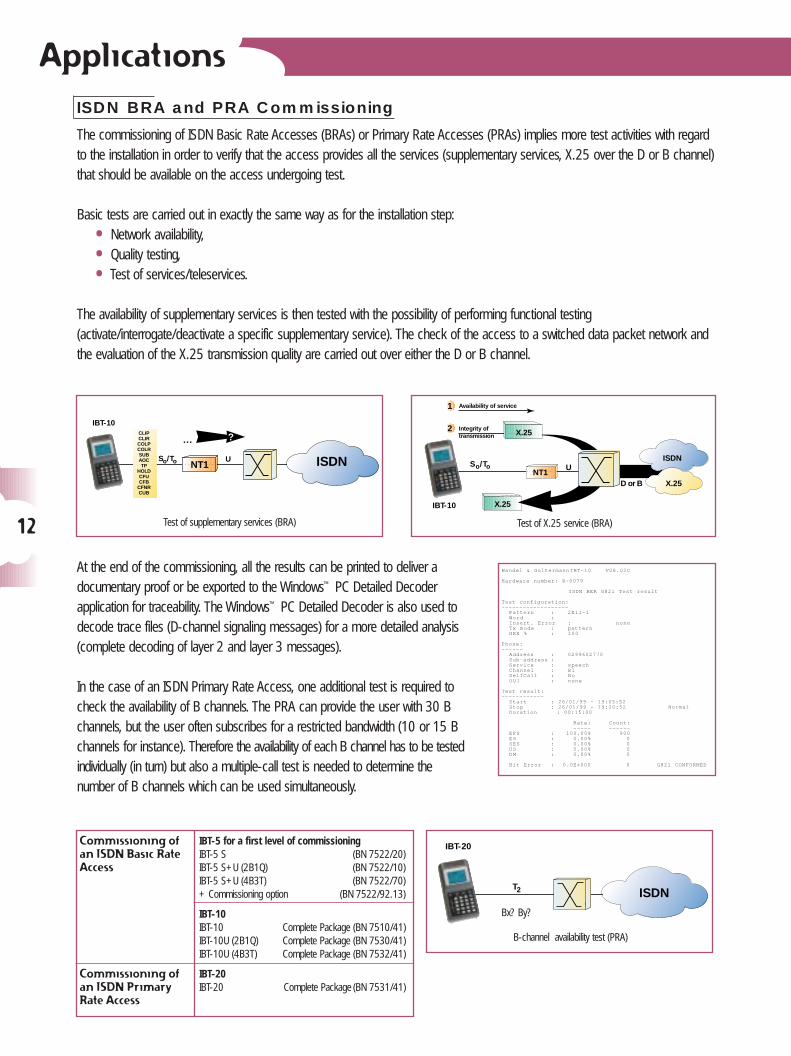
The power provided by the NT1 should then to be checked.Measuring the voltage is not sufficient. The tester should place a specific load on the bus to detect if some power is present.
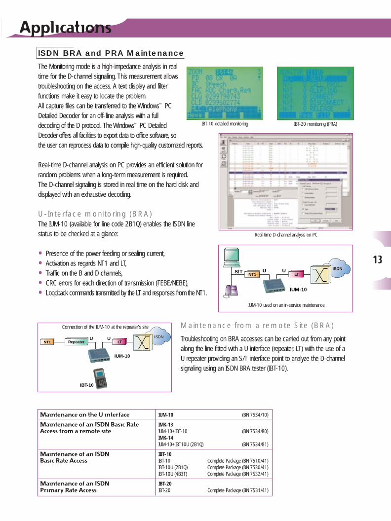
All test results have to be printed or transferred to a PC, thus adocumentary proof can be delivered and archived.
Cable testing
U ISDN
PS1PS1 + load
PS2PS2 + loadTx activityRx activityISDN traffic
NT1S /To o
Working memory
Measurements
Cable Settings
Data memory
Project x Project y
PC
Active ISDN bus
Satellite
Satellite
Length to open circuit
Length to short circuit
Installation, maintenance and commissioning of structured cabling at customer premises
IST-15IST-15 (BN 7533/40)
IMK-1XIMK-10 (IST-15 + IBT-10) (BN 7533/80)IMK-11 (IST-15 + IBT-10U 2B1Q) (BN 7533/81)IMK-12 (IST-15 + IBT-10U 4B3T) (BN 7533/82)
Applications
11
ISDN BRA and PRA Installation
The installation of an ISDN access (BRA or PRA) mainly consists in testing the availability of the network by making a simple phone call, carrying out a quick quality check of the access (BER Test) and verifying the availability of services and teleservices (the subscriber is expecting not only the ability to make only speech phone calls but also data communications or specific teleser-vices such as Fax G4).All these tests can be carried out on the S interface or directly on the U interface if the NT1 has not yet been installed.
In case of problems, the D-channel tracer allows the user to examine signaling messages to easily locate the problem (Layer 1, Layer 2 or Layer 3 problem).
Installation of an ISDN Basic Rate Access
Installation of an ISDN Primary Rate Access
IBT-10IBT-10 Basic Package (BN 7510/40)IBT-10U (2B1Q) Basic Package (BN 7530/40)IBT-10U (4B3T) Basic Package (BN 7532/40)
IBT-20IBT-20 Basic Package (BN 7531/40)
NT1
IBT-5 S and U
IBT-5 S
U
U
ISDNS /To o
IBT-5
10110110
01101101
10110110
01101101
NT1
B1
B2
Terminal simulation (BRA)
IBT-10 Tracer (BRA)
BER Test in self-call mode (BRA)
IBT-20
T ISDN
?…EDSS-1
Speech BCAudio 3.1 kHz
Data 64 BCData 56 BC
SpeechFax G3Fax G4Teletext
Videotext
2
Test of services (PRA)
IBT-5IBT-5 S (BN 7522/20)IBT-5 S+U (2B1Q) (BN 7522/10)IBT-5 S+U (4B3T) (BN 7522/70)
ApplicationsISDN BRA and PRA Commissioning
The commissioning of ISDN Basic Rate Accesses (BRAs) or Primary Rate Accesses (PRAs) implies more test activities with regardto the installation in order to verify that the access provides all the services (supplementary services, X.25 over the D or B channel)that should be available on the access undergoing test.
Basic tests are carried out in exactly the same way as for the installation step:
• Network availability,
• Quality testing,
• Test of services/teleservices.
The availability of supplementary services is then tested with the possibility of performing functional testing(activate/interrogate/deactivate a specific supplementary service). The check of the access to a switched data packet network andthe evaluation of the X.25 transmission quality are carried out over either the D or B channel.
At the end of the commissioning, all the results can be printed to deliver a documentary proof or be exported to the Windows™ PC Detailed Decoder application for traceability. The Windows™ PC Detailed Decoder is also used todecode trace files (D-channel signaling messages) for a more detailed analysis(complete decoding of layer 2 and layer 3 messages).
In the case of an ISDN Primary Rate Access, one additional test is required tocheck the availability of B channels. The PRA can provide the user with 30 Bchannels, but the user often subscribes for a restricted bandwidth (10 or 15 Bchannels for instance). Therefore the availability of each B channel has to be testedindividually (in turn) but also a multiple-call test is needed to determine the number of B channels which can be used simultaneously.
Commissioning ofan ISDN Basic RateAccess
Commissioning ofan ISDN Primary Rate Access
IBT-20IBT-20 Complete Package (BN 7531/41)
IBT-5 for a first level of commissioningIBT-5 S (BN 7522/20)IBT-5 S+U (2B1Q) (BN 7522/10)IBT-5 S+U (4B3T) (BN 7522/70)+ Commissioning option (BN 7522/92.13)
IBT-10IBT-10 Complete Package (BN 7510/41)IBT-10U (2B1Q) Complete Package (BN 7530/41)IBT-10U (4B3T) Complete Package (BN 7532/41)
IBT-10
U ISDN
?…CLIPCLIRCOLPCOLRSUBAOCTP
HOLDCFUCFB
CFNRCUB
NT1So/To
Test of supplementary services (BRA)
IBT-20
ISDNT2
B-channel availability test (PRA)
Bx? By?
IBT-10
NT1U
ISDN
X.25
X.25
X.25
Availability of service1
Integrity oftransmission
2
D or B
/ToSo
Test of X.25 service (BRA)12
Wandel & Goltermann IBT-10 V08.02C
Hardware number: R-0079
ISDN BER G821 Test result
Test configuration:—————————----------
Pattern : 2E11-1Word :Insert. Error : noneTx mode : patternHRX % : 100
Phone:——----
Address : 0299602770Sub-address :Service : speechChannel : B1SelfCall : NoUUI : none
Test result:—————-------
Start : 26/01/99 - 19:05:52Stop : 26/01/99 - 19:20:52 NormalDuration : 00:15:00
Rate: Count:---—— ---——-
EFS : 100.00% 900ES : 0.00% 0SES : 0.00% 0US : 0.00% 0DM : 0.00% 0
Bit Error : 0.0E+000 0 G821 CONFORMED
ISDN BRA and PRA Maintenance
The Monitoring mode is a high-impedance analysis in realtime for the D-channel signaling. This measurement allowstroubleshooting on the access. A text display and filterfunctions make it easy to locate the problem.All capture files can be transferred to the Windows™ PCDetailed Decoder for an off-line analysis with a full decoding of the D protocol. The Windows™ PC DetailedDecoder offers all facilities to export data to office software, so the user can reprocess data to compile high-quality customized reports.
Real-time D-channel analysis on PC provides an efficient solution forrandom problems when a long-term measurement is required.The D-channel signaling is stored in real time on the hard disk and displayed with an exhaustive decoding.
U-Interface monitoring (BRA)The IUM-10 (available for line code 2B1Q) enables the ISDN line status to be checked at a glance:
• Presence of the power feeding or sealing current,
• Activation as regards NT1 and LT,
• Traffic on the B and D channels,
• CRC errors for each direction of transmission (FEBE/NEBE),
• Loopback commands transmitted by the LT and responses from the NT1.
Maintenance from a remote Site (BRA)
Troubleshooting on BRA accesses can be carried out from any pointalong the line fitted with a U interface (repeater, LT) with the use of a U repeater providing an S/T interface point to analyze the D-channelsignaling using an ISDN BRA tester (IBT-10).
Applications
13
Maintenance on the U interface
Maintenance of an ISDN Basic RateAccess from a remote site
Maintenance of an ISDN Basic Rate Access
Maintenance of an ISDN Primary Rate Access
IBT-10IBT-10 Complete Package (BN 7510/41)IBT-10U (2B1Q) Complete Package (BN 7530/41)IBT-10U (4B3T) Complete Package (BN 7532/41)
IUM-10 (BN 7534/10)
IMK-13IUM-10+IBT-10 (BN 7534/80)IMK-14IUM-10+IBT10U (2B1Q) (BN 7534/81)
IUM-10
NT1S/T UU ISDN
LT
IUM-10
RepeaterNT1
UU
IBT-10
LTISDN
IBT-20 monitoring (PRA)IBT-10 detailed monitoring
IBT-20IBT-20 Complete Package (BN 7531/41)
Real-time D-channel analysis on PC
IUM-10 used on an in-service maintenance
Connection of the IUM-10 at the repeater’s site
14
ISDN Equipment Installation and Maintenance
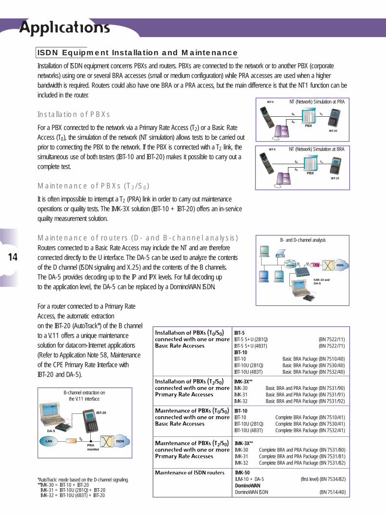
Installation of ISDN equipment concerns PBXs and routers. PBXs are connected to the network or to another PBX (corporate networks) using one or several BRA accesses (small or medium configuration) while PRA accesses are used when a higher bandwidth is required. Routers could also have one BRA or a PRA access, but the main difference is that the NT1 function can beincluded in the router.
Installation of PBXs
For a PBX connected to the network via a Primary Rate Access (T2) or a Basic RateAccess (T0), the simulation of the network (NT simulation) allows tests to be carried outprior to connecting the PBX to the network. If the PBX is connected with a T2 link, thesimultaneous use of both testers (IBT-10 and IBT-20) makes it possible to carry out acomplete test.
Maintenance of PBXs (T2/S0)
It is often impossible to interrupt a T2 (PRA) link in order to carry out maintenance operations or quality tests. The IMK-3X solution (IBT-10 + IBT-20) offers an in-service quality measurement solution.
Maintenance of routers (D- and B-channel analysis)Routers connected to a Basic Rate Access may include the NT and are thereforeconnected directly to the U interface. The DA-5 can be used to analyze the contents of the D channel (ISDN signaling and X.25) and the contents of the B channels.The DA-5 provides decoding up to the IP and IPX levels. For full decoding up to the application level, the DA-5 can be replaced by a DominoWAN ISDN.
For a router connected to a Primary RateAccess, the automatic extraction on the IBT-20 (AutoTrack*) of the B channel to a V.11 offers a unique maintenance solution for datacom-Internet applications(Refer to Application Note 58, Maintenanceof the CPE Primary Rate Interface with IBT-20 and DA-5).
Installation of PBXs (T0/S0) connected with one or more Basic Rate Accesses
Installation of PBXs (T2/S0) connected with one or morePrimary Rate Accesses
Maintenance of PBXs (T0/S0)connected with one or moreBasic Rate Accesses
Maintenance of PBXs (T2/S0)connected with one or morePrimary Rate Accesses
Maintenance of ISDN routers
IBT-10 IBT-10 Complete BRA Package (BN 7510/41)IBT-10U (2B1Q) Complete BRA Package (BN 7530/41)IBT-10U (4B3T) Complete BRA Package (BN 7532/41)
IMK-3X** IMK-30 Basic BRA and PRA Package (BN 7531/90)IMK-31 Basic BRA and PRA Package (BN 7531/91)IMK-32 Basic BRA and PRA Package (BN 7531/92)
IBT-5IBT-5 S+U (2B1Q) (BN 7522/11)IBT-5 S+U (4B3T) (BN 7522/71)IBT-10IBT-10 Basic BRA Package (BN 7510/40)IBT-10U (2B1Q) Basic BRA Package (BN 7530/40)IBT-10U (4B3T) Basic BRA Package (BN 7532/40)
IMK-3X**IMK-30 Complete BRA and PRA Package (BN 7531/80)IMK-31 Complete BRA and PRA Package (BN 7531/81)IMK-32 Complete BRA and PRA Package (BN 7531/82)
IMK-50IUM-10 + DA-5 (first level) (BN 7534/82)DominoWANDominoWAN ISDN (BN 7514/40)
PBX
IBT-5
IBT-20
S o T 2
S o
ISDN
IUM-10 and DA-5
LTROUTERUU
ISDN
IBT-20
DA-5
PRAmonitor
LANT2
PBX
IBT-5
IBT-10
S o T o
S o
NT (Network) Simulation at PRA
NT (Network) Simulation at BRA
B- and D-channel analysis
B-channel extraction on the V.11 interface
*AutoTrack: mode based on the D-channel signaling.**IMK-30 = IBT-10 + IBT-20
IMK-31 = IBT-10U (2B1Q) + IBT-20IMK-32 = IBT-10U (4B3T) + IBT-20
Applications
15
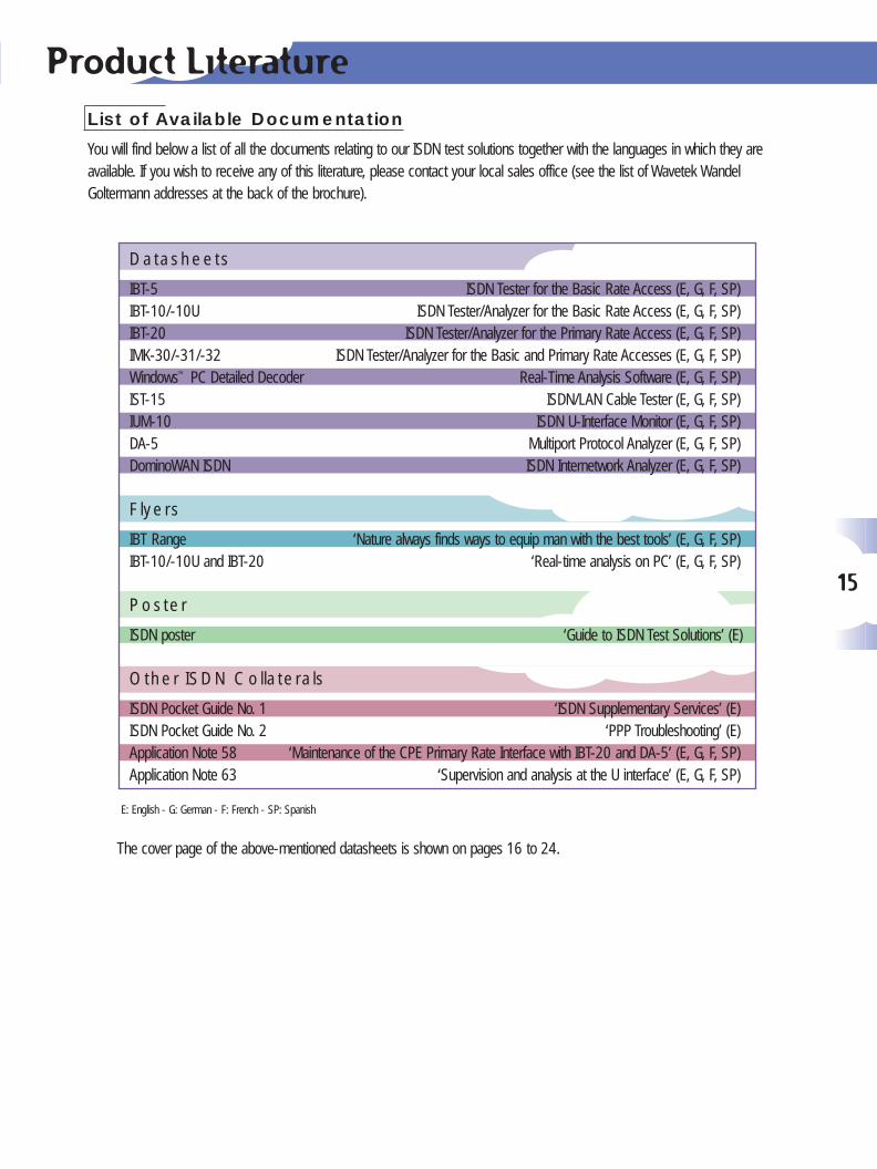
Product LiteratureList of Available Documentation
You will find below a list of all the documents relating to our ISDN test solutions together with the languages in which they are available. If you wish to receive any of this literature, please contact your local sales office (see the list of Wavetek WandelGoltermann addresses at the back of the brochure).
Datasheets
IBT-5 ISDN Tester for the Basic Rate Access (E, G, F, SP)IBT-10/-10U ISDN Tester/Analyzer for the Basic Rate Access (E, G, F, SP)IBT-20 ISDN Tester/Analyzer for the Primary Rate Access (E, G, F, SP)IMK-30/-31/-32 ISDN Tester/Analyzer for the Basic and Primary Rate Accesses (E, G, F, SP)Windows™ PC Detailed Decoder Real-Time Analysis Software (E, G, F, SP)IST-15 ISDN/LAN Cable Tester (E, G, F, SP)IUM-10 ISDN U-Interface Monitor (E, G, F, SP)DA-5 Multiport Protocol Analyzer (E, G, F, SP)DominoWAN ISDN ISDN Internetwork Analyzer (E, G, F, SP)
Flyers
IBT Range ‘Nature always finds ways to equip man with the best tools’ (E, G, F, SP)IBT-10/-10U and IBT-20 ‘Real-time analysis on PC’ (E, G, F, SP)
Poster
ISDN poster ‘Guide to ISDN Test Solutions’ (E)
Other ISDN Collaterals
ISDN Pocket Guide No. 1 ‘ISDN Supplementary Services’ (E)ISDN Pocket Guide No. 2 ‘PPP Troubleshooting’ (E)Application Note 58 ‘Maintenance of the CPE Primary Rate Interface with IBT-20 and DA-5’ (E, G, F, SP)Application Note 63 ‘Supervision and analysis at the U interface’ (E, G, F, SP)
E: English - G: German - F: French - SP: Spanish
The cover page of the above-mentioned datasheets is shown on pages 16 to 24.
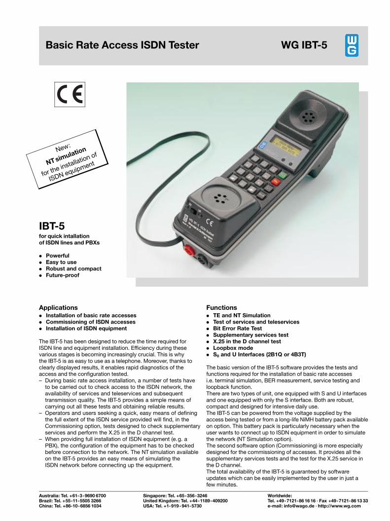
Applications. Installation of basic rate accesses. Commissioning of ISDN accesses. Installation of ISDN equipment
The IBT-5 has been designed to reduce the time required forISDN line and equipment installation. Efficiency during thesevarious stages is becoming increasingly crucial. This is whythe IBT-5 is as easy to use as a telephone. Moreover, thanks toclearly displayed results, it enables rapid diagnostics of theaccess and the configuration tested.± During basic rate access installation, a number of tests have
to be carried out to check access to the ISDN network, theavailability of services and teleservices and subsequenttransmission quality. The IBT-5 provides a simple means ofcarrying out all these tests and obtaining reliable results.
± Operators and users seeking a quick, easy means of definingthe full extent of the ISDN service provided will find, in theCommissioning option, tests designed to check supplementaryservices and perform the X.25 in the D channel test.
± When providing full installation of ISDN equipment (e.g. aPBX), the configuration of the equipment has to be checkedbefore connection to the network. The NT simulation availableon the IBT-5 provides an easy means of simulating theISDN network before connecting up the equipment.
Functions. TE and NT Simulation. Test of services and teleservices. Bit Error Rate Test. Supplementary services test. X.25 in the D channel test. Loopbox mode. S0 and U Interfaces (2B1Q or 4B3T)
The basic version of the IBT-5 software provides the tests andfunctions required for the installation of basic rate accessesi.e. terminal simulation, BER measurement, service testing andloopback function.There are two types of unit, one equipped with S and U interfacesand one equipped with only the S interface. Both are robust,compact and designed for intensive daily use.The IBT-5 can be powered from the voltage supplied by theaccess being tested or from a long-life NiMH battery pack availableon option. This battery pack is particularly necessary when theuser wants to connect up to ISDN equipment in order to simulatethe network (NT Simulation option).The second software option (Commissioning) is more especiallydesigned for the commissioning of accesses. It provides all thesupplementary services tests and the test for the X.25 service inthe D channel.The total availability of the IBT-5 is guaranteed by softwareupdates which can be easily implemented by the user in just afew minutes.
IBT-5for quick intallationof ISDN lines and PBXs
. Powerful
. Easy to use
. Robust and compact
. Future-proof
New:
NTsimulation
for the installation of
ISDN equipment
Basic Rate Access ISDN Tester WG IBT-5
Australia: Tel. +61-3-9690 6700Brazil: Tel. +55-11-5505 3266China: Tel. +86-10-6856 1034
Singapore: Tel. +65-356-3246United Kingdom: Tel. +44-1189-409200USA: Tel. +1-919-941-5730
Worldwide:Tel. +49-7121-86 16 16 ´ Fax +49-7121-86 13 33e-mail: [email protected] ´ http://www.wg.com
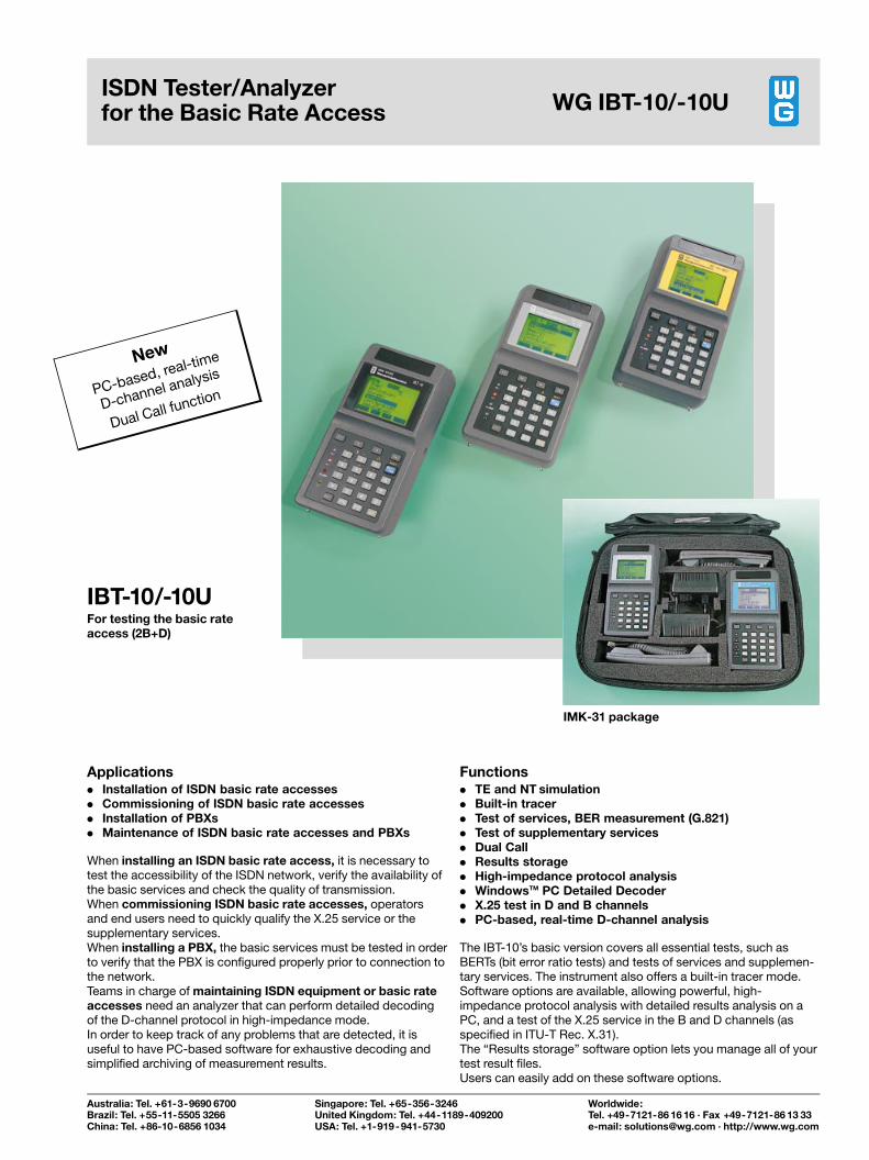
IMK-31 package
Applications. Installation of ISDN basic rate accesses. Commissioning of ISDN basic rate accesses. Installation of PBXs. Maintenance of ISDN basic rate accesses and PBXs
When installing an ISDN basic rate access, it is necessary totest the accessibility of the ISDN network, verify the availability ofthe basic services and check the quality of transmission.When commissioning ISDN basic rate accesses, operatorsand end users need to quickly qualify the X.25 service or thesupplementary services.When installing a PBX, the basic services must be tested in orderto verify that the PBX is configured properly prior to connection tothe network.Teams in charge of maintaining ISDN equipment or basic rateaccesses need an analyzer that can perform detailed decodingof the D-channel protocol in high-impedance mode.In order to keep track of any problems that are detected, it isuseful to have PC-based software for exhaustive decoding andsimplified archiving of measurement results.
Functions. TE and NT simulation. Built-in tracer. Test of services, BER measurement (G.821). Test of supplementary services. Dual Call. Results storage. High-impedance protocol analysis. WindowsTM PC Detailed Decoder. X.25 test in D and B channels. PC-based, real-time D-channel analysis
The IBT-10's basic version covers all essential tests, such asBERTs (bit error ratio tests) and tests of services and supplemen-tary services. The instrument also offers a built-in tracer mode.Software options are available, allowing powerful, high-impedance protocol analysis with detailed results analysis on aPC, and a test of the X.25 service in the B and D channels (asspecified in ITU-T Rec. X.31).The ªResults storageº software option lets you manage all of yourtest result files.Users can easily add on these software options.
IBT-10/-10UFor testing the basic rateaccess (2B+D)
ISDN Tester/Analyzerfor the Basic Rate Access WG IBT-10/-10U
New
PC-based, real-time
D-channel analysis
Dual Call function
Australia: Tel. +61-3-9690 6700Brazil: Tel. +55-11-5505 3266China: Tel. +86-10-6856 1034
Singapore: Tel. +65-356-3246United Kingdom: Tel. +44-1189-409200USA: Tel. +1-919-941-5730
Worldwide:Tel. +49-7121-86 16 16 ´ Fax +49-7121-86 13 33e-mail: [email protected] ´ http://www.wg.com
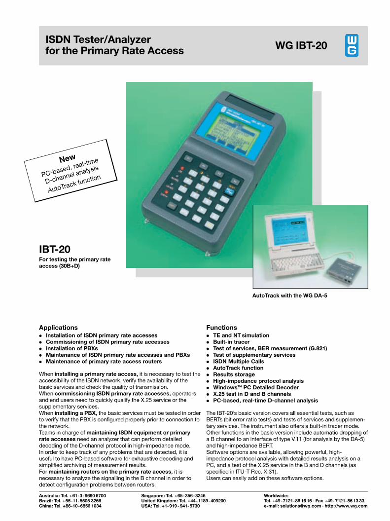
AutoTrack with the WG DA-5
Applications. Installation of ISDN primary rate accesses. Commissioning of ISDN primary rate accesses. Installation of PBXs. Maintenance of ISDN primary rate accesses and PBXs. Maintenance of primary rate access routers
When installing a primary rate access, it is necessary to test theaccessibility of the ISDN network, verify the availability of thebasic services and check the quality of transmission.When commissioning ISDN primary rate accesses, operatorsand end users need to quickly qualify the X.25 service or thesupplementary services.When installing a PBX, the basic services must be tested in orderto verify that the PBX is configured properly prior to connection tothe network.Teams in charge of maintaining ISDN equipment or primaryrate accesses need an analyzer that can perform detaileddecoding of the D-channel protocol in high-impedance mode.In order to keep track of any problems that are detected, it isuseful to have PC-based software for exhaustive decoding andsimplified archiving of measurement results.For maintaining routers on the primary rate access, it isnecessary to analyze the signalling in the B channel in order todetect configuration problems between routers.
Functions. TE and NT simulation. Built-in tracer. Test of services, BER measurement (G.821). Test of supplementary services. ISDN Multiple Calls. AutoTrack function. Results storage. High-impedance protocol analysis. WindowsTM PC Detailed Decoder. X.25 test in D and B channels. PC-based, real-time D-channel analysis
The IBT-20's basic version covers all essential tests, such asBERTs (bit error ratio tests) and tests of services and supplemen-tary services. The instrument also offers a built-in tracer mode.Other functions in the basic version include automatic dropping ofa B channel to an interface of type V.11 (for analysis by the DA-5)and high-impedance BERT.Software options are available, allowing powerful, high-impedance protocol analysis with detailed results analysis on aPC, and a test of the X.25 service in the B and D channels (asspecified in ITU-T Rec. X.31).Users can easily add on these software options.
IBT-20For testing the primary rateaccess (30B+D)
ISDN Tester/Analyzerfor the Primary Rate Access WG IBT-20
New
PC-based, real-time
D-channel analysis
AutoTrack function
Australia: Tel. +61-3-9690 6700Brazil: Tel. +55-11-5505 3266China: Tel. +86-10-6856 1034
Singapore: Tel. +65-356-3246United Kingdom: Tel. +44-1189-409200USA: Tel. +1-919-941-5730
Worldwide:Tel. +49-7121-86 16 16 ´ Fax +49-7121-86 13 33e-mail: [email protected] ´ http://www.wg.com
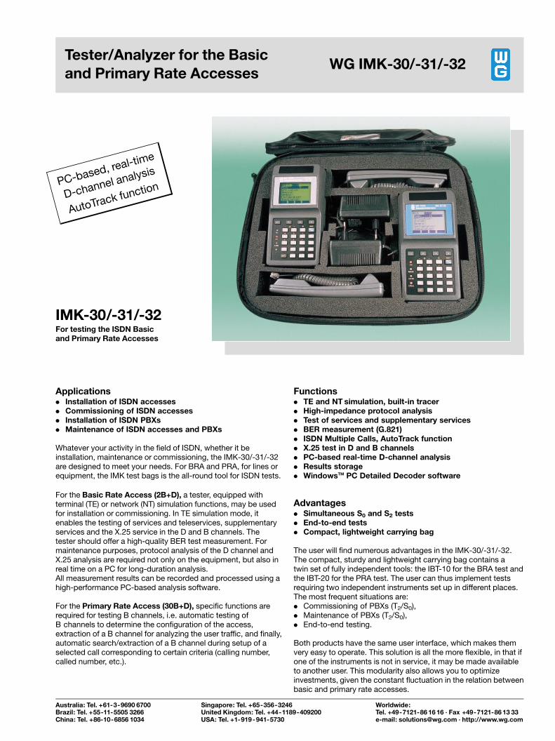
Applications. Installation of ISDN accesses. Commissioning of ISDN accesses. Installation of ISDN PBXs. Maintenance of ISDN accesses and PBXs
Whatever your activity in the field of ISDN, whether it beinstallation, maintenance or commissioning, the IMK-30/-31/-32are designed to meet your needs. For BRA and PRA, for lines orequipment, the IMK test bags is the all-round tool for ISDN tests.
For the Basic Rate Access (2B+D), a tester, equipped withterminal (TE) or network (NT) simulation functions, may be usedfor installation or commissioning. In TE simulation mode, itenables the testing of services and teleservices, supplementaryservices and the X.25 service in the D and B channels. Thetester should offer a high-quality BER test measurement. Formaintenance purposes, protocol analysis of the D channel andX.25 analysis are required not only on the equipment, but also inreal time on a PC for long-duration analysis.All measurement results can be recorded and processed using ahigh-performance PC-based analysis software.
For the Primary Rate Access (30B+D), specific functions arerequired for testing B channels, i.e. automatic testing ofB channels to determine the configuration of the access,extraction of a B channel for analyzing the user traffic, and finally,automatic search/extraction of a B channel during setup of aselected call corresponding to certain criteria (calling number,called number, etc.).
Functions. TE and NT simulation, built-in tracer. High-impedance protocol analysis. Test of services and supplementary services. BER measurement (G.821). ISDN Multiple Calls, AutoTrack function. X.25 test in D and B channels. PC-based real-time D-channel analysis. Results storage. WindowsTM PC Detailed Decoder software
Advantages. Simultaneous S0 and S2 tests. End-to-end tests. Compact, lightweight carrying bag
The user will find numerous advantages in the IMK-30/-31/-32.The compact, sturdy and lightweight carrying bag contains atwin set of fully independent tools: the IBT-10 for the BRA test andthe IBT-20 for the PRA test. The user can thus implement testsrequiring two independent instruments set up in different places.The most frequent situations are:. Commissioning of PBXs (T2/S0),. Maintenance of PBXs (T2/S0),. End-to-end testing.
Both products have the same user interface, which makes themvery easy to operate. This solution is all the more flexible, in that ifone of the instruments is not in service, it may be made availableto another user. This modularity also allows you to optimizeinvestments, given the constant fluctuation in the relation betweenbasic and primary rate accesses.
IMK-30/-31/-32For testing the ISDN Basicand Primary Rate Accesses
Tester/Analyzer for the Basicand Primary Rate Accesses
WG IMK-30/-31/-32
PC-based, real-time
D-channel analysis
AutoTrack function
Australia: Tel. +61-3-9690 6700Brazil: Tel. +55-11-5505 3266China: Tel. +86-10-6856 1034
Singapore: Tel. +65-356-3246United Kingdom: Tel. +44-1189-409200USA: Tel. +1-919-941-5730
Worldwide:Tel. +49-7121-86 16 16 ´ Fax +49-7121-86 13 33e-mail: [email protected] ´ http://www.wg.com
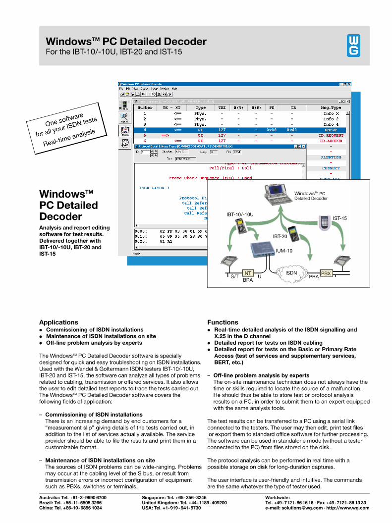
Applications. Commissioning of ISDN installations. Maintenance of ISDN installations on site. Off-line problem analysis by experts
The WindowsTM PC Detailed Decoder software is speciallydesigned for quick and easy troubleshooting on ISDN installations.Used with the Wandel & Goltermann ISDN testers IBT-10/-10U,IBT-20 and IST-15, the software can analyze all types of problemsrelated to cabling, transmission or offered services. It also allowsthe user to edit detailed test reports to trace the tests carried out.The WindowsTM PC Detailed Decoder software covers thefollowing fields of application:
± Commissioning of ISDN installationsThere is an increasing demand by end customers for aªmeasurement slipº giving details of the tests carried out, inaddition to the list of services actually available. The serviceprovider should be able to file the results and print them in acustomizable format.
± Maintenance of ISDN installations on siteThe sources of ISDN problems can be wide-ranging. Problemsmay occur at the cabling level of the S bus, or result fromtransmission errors or incorrect configuration of equipmentsuch as PBXs, switches or terminals.
Functions. Real-time detailed analysis of the ISDN signalling and
X.25 in the D channel. Detailed report for tests on ISDN cabling. Detailed report for tests on the Basic or Primary Rate
Access (test of services and supplementary services,BERT, etc.)
± Off-line problem analysis by expertsThe on-site maintenance technician does not always have thetime or skills required to locate the source of a malfunction.He should thus be able to store test or protocol analysisresults on a PC, in order to submit them to an expert equippedwith the same analysis tools.
The test results can be transferred to a PC using a serial linkconnected to the testers. The user may then edit, print test filesor export them to standard office software for further processing.The software can be used in standalone mode (without a testerconnected to the PC) from files stored on the disk.
The protocol analysis can be performed in real time with apossible storage on disk for long-duration captures.
The user interface is user-friendly and intuitive. The commandsare the same whatever the type of tester used.
WindowsTM
PC DetailedDecoderAnalysis and report editingsoftware for test results.Delivered together withIBT-10/-10U, IBT-20 andIST-15
Australia: Tel. +61-3-9690 6700Brazil: Tel. +55-11-5505 3266China: Tel. +86-10-6856 1034
Singapore: Tel. +65-356-3246United Kingdom: Tel. +44-1189-409200USA: Tel. +1-919-941-5730
Worldwide:Tel. +49-7121-86 16 16 ´ Fax +49-7121-86 13 33e-mail: [email protected] ´ http://www.wg.com
WindowsTM PC Detailed DecoderFor the IBT-10/-10U, IBT-20 and IST-15
One software
for all your ISDN tests
Real-time analysis
PBXNT
BRA
ISDNS/T U
IUM-10
IBT-20
IBT-10/-10U
WindowsTM PCDetailed Decoder
IST-15
PRA
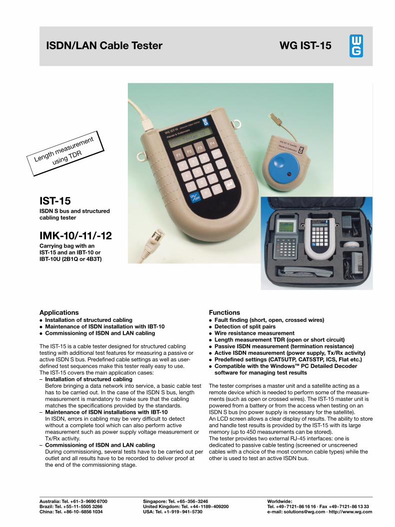
Applications. Installation of structured cabling. Maintenance of ISDN installation with IBT-10. Commissioning of ISDN and LAN cabling
The IST-15 is a cable tester designed for structured cablingtesting with additional test features for measuring a passive oractive ISDN S bus. Predefined cable settings as well as user-defined test sequences make this tester really easy to use.The IST-15 covers the main application cases:± Installation of structured cabling
Before bringing a data network into service, a basic cable testhas to be carried out. In the case of the ISDN S bus, lengthmeasurement is mandatory to make sure that the cablingmatches the specifications provided by the standards.
± Maintenance of ISDN installations with IBT-10In ISDN, errors in cabling may be very difficult to detectwithout a complete tool which can also perform activemeasurement such as power supply voltage measurement orTx/Rx activity.
± Commissioning of ISDN and LAN cablingDuring commissioning, several tests have to be carried out peroutlet and all results have to be recorded to deliver proof atthe end of the commissioning stage.
Functions. Fault finding (short, open, crossed wires). Detection of split pairs. Wire resistance measurement. Length measurement TDR (open or short circuit). Passive ISDN measurement (termination resistance). Active ISDN measurement (power supply, Tx/Rx activity). Predefined settings (CAT5UTP, CAT5STP, ICS, Flat etc.). Compatible with the WindowsTM PC Detailed Decoder
software for managing test results
The tester comprises a master unit and a satellite acting as aremote device which is needed to perform some of the measure-ments (such as open or crossed wires). The IST-15 master unit ispowered from a battery or from the access when testing on anISDN S bus (no power supply is necessary for the satellite).An LCD screen allows a clear display of results. The ability to storeand handle test results is provided by the IST-15 with its largememory (up to 450 measurements can be stored).The tester provides two external RJ-45 interfaces: one isdedicated to passive cable testing (screened or unscreenedcables with a choice of the most common cable types) while theother is used to test an active ISDN bus.
IST-15ISDN S bus and structuredcabling tester
IMK-10/-11/-12Carrying bag with anIST-15 and an IBT-10 orIBT-10U (2B1Q or 4B3T)
ISDN/LAN Cable Tester WG IST-15
Length measurement
using TDR
Australia: Tel. +61-3-9690 6700Brazil: Tel. +55-11-5505 3266China: Tel. +86-10-6856 1034
Singapore: Tel. +65-356-3246United Kingdom: Tel. +44-1189-409200USA: Tel. +1-919-941-5730
Worldwide:Tel. +49-7121-86 16 16 ´ Fax +49-7121-86 13 33e-mail: [email protected] ´ http://www.wg.com
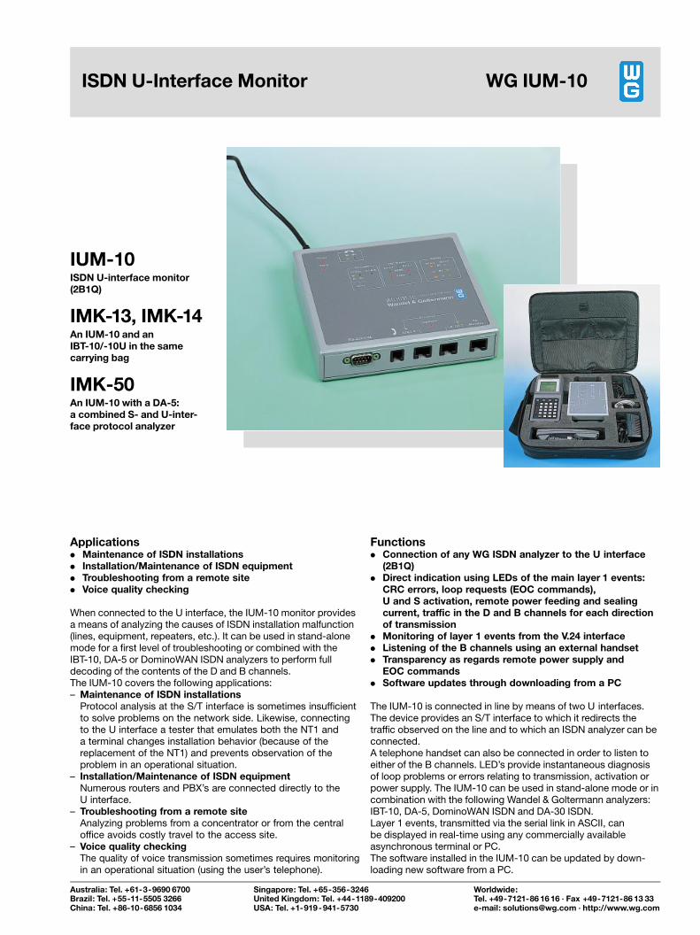
Applications. Maintenance of ISDN installations. Installation/Maintenance of ISDN equipment. Troubleshooting from a remote site. Voice quality checking
When connected to the U interface, the IUM-10 monitor providesa means of analyzing the causes of ISDN installation malfunction(lines, equipment, repeaters, etc.). It can be used in stand-alonemode for a first level of troubleshooting or combined with theIBT-10, DA-5 or DominoWAN ISDN analyzers to perform fulldecoding of the contents of the D and B channels.The IUM-10 covers the following applications:± Maintenance of ISDN installations
Protocol analysis at the S/T interface is sometimes insufficientto solve problems on the network side. Likewise, connectingto the U interface a tester that emulates both the NT1 anda terminal changes installation behavior (because of thereplacement of the NT1) and prevents observation of theproblem in an operational situation.
± Installation/Maintenance of ISDN equipmentNumerous routers and PBX's are connected directly to theU interface.
± Troubleshooting from a remote siteAnalyzing problems from a concentrator or from the centraloffice avoids costly travel to the access site.
± Voice quality checkingThe quality of voice transmission sometimes requires monitoringin an operational situation (using the user's telephone).
Functions. Connection of any WG ISDN analyzer to the U interface
(2B1Q). Direct indication using LEDs of the main layer 1 events:
CRC errors, loop requests (EOC commands),U and S activation, remote power feeding and sealingcurrent, traffic in the D and B channels for each directionof transmission
. Monitoring of layer 1 events from the V.24 interface
. Listening of the B channels using an external handset
. Transparency as regards remote power supply andEOC commands
. Software updates through downloading from a PC
The IUM-10 is connected in line by means of two U interfaces.The device provides an S/T interface to which it redirects thetraffic observed on the line and to which an ISDN analyzer can beconnected.A telephone handset can also be connected in order to listen toeither of the B channels. LED's provide instantaneous diagnosisof loop problems or errors relating to transmission, activation orpower supply. The IUM-10 can be used in stand-alone mode or incombination with the following Wandel & Goltermann analyzers:IBT-10, DA-5, DominoWAN ISDN and DA-30 ISDN.Layer 1 events, transmitted via the serial link in ASCII, canbe displayed in real-time using any commercially availableasynchronous terminal or PC.The software installed in the IUM-10 can be updated by down-loading new software from a PC.
IUM-10ISDN U-interface monitor(2B1Q)
IMK-13, IMK-14An IUM-10 and anIBT-10/-10U in the samecarrying bag
IMK-50An IUM-10 with a DA-5:a combined S- and U-inter-face protocol analyzer
ISDN U-Interface Monitor WG IUM-10
Australia: Tel. +61-3-9690 6700Brazil: Tel. +55-11-5505 3266China: Tel. +86-10-6856 1034
Singapore: Tel. +65-356-3246United Kingdom: Tel. +44-1189-409200USA: Tel. +1-919-941-5730
Worldwide:Tel. +49-7121-86 16 16 ´ Fax +49-7121-86 13 33e-mail: [email protected] ´ http://www.wg.com
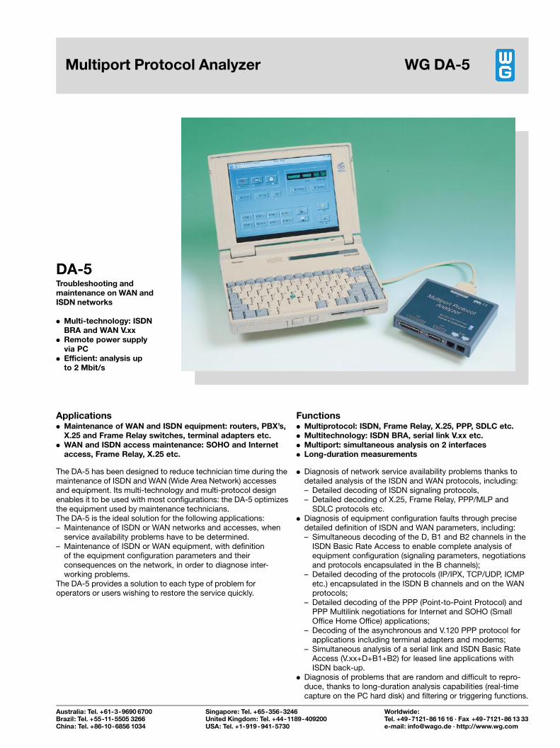
Applications. Maintenance of WAN and ISDN equipment: routers, PBX's,
X.25 and Frame Relay switches, terminal adapters etc.. WAN and ISDN access maintenance: SOHO and Internet
access, Frame Relay, X.25 etc.
The DA-5 has been designed to reduce technician time during themaintenance of ISDN and WAN (Wide Area Network) accessesand equipment. Its multi-technology and multi-protocol designenables it to be used with most configurations: the DA-5 optimizesthe equipment used by maintenance technicians.The DA-5 is the ideal solution for the following applications:± Maintenance of ISDN or WAN networks and accesses, when
service availability problems have to be determined.± Maintenance of ISDN or WAN equipment, with definition
of the equipment configuration parameters and theirconsequences on the network, in order to diagnose inter-working problems.
The DA-5 provides a solution to each type of problem foroperators or users wishing to restore the service quickly.
Functions. Multiprotocol: ISDN, Frame Relay, X.25, PPP, SDLC etc.. Multitechnology: ISDN BRA, serial link V.xx etc.. Multiport: simultaneous analysis on 2 interfaces. Long-duration measurements
. Diagnosis of network service availability problems thanks todetailed analysis of the ISDN and WAN protocols, including:± Detailed decoding of ISDN signaling protocols,± Detailed decoding of X.25, Frame Relay, PPP/MLP and
SDLC protocols etc.. Diagnosis of equipment configuration faults through precise
detailed definition of ISDN and WAN parameters, including:± Simultaneous decoding of the D, B1 and B2 channels in the
ISDN Basic Rate Access to enable complete analysis ofequipment configuration (signaling parameters, negotiationsand protocols encapsulated in the B channels);
± Detailed decoding of the protocols (IP/IPX, TCP/UDP, ICMPetc.) encapsulated in the ISDN B channels and on the WANprotocols;
± Detailed decoding of the PPP (Point-to-Point Protocol) andPPP Multilink negotiations for Internet and SOHO (SmallOffice Home Office) applications;
± Decoding of the asynchronous and V.120 PPP protocol forapplications including terminal adapters and modems;
± Simultaneous analysis of a serial link and ISDN Basic RateAccess (V.xx+D+B1+B2) for leased line applications withISDN back-up.
. Diagnosis of problems that are random and difficult to repro-duce, thanks to long-duration analysis capabilities (real-timecapture on the PC hard disk) and filtering or triggering functions.
DA-5Troubleshooting andmaintenance on WAN andISDN networks
. Multi-technology: ISDNBRA and WAN V.xx
. Remote power supplyvia PC
. Efficient: analysis upto 2 Mbit/s
Multiport Protocol Analyzer WG DA-5
Australia: Tel. +61-3-9690 6700Brazil: Tel. +55-11-5505 3266China: Tel. +86-10-6856 1034
Singapore: Tel. +65-356-3246United Kingdom: Tel. +44-1189-409200USA: Tel. +1-919-941-5730
Worldwide:Tel. +49-7121-86 16 16 ´ Fax +49-7121-86 13 33e-mail: [email protected] ´ http://www.wg.com
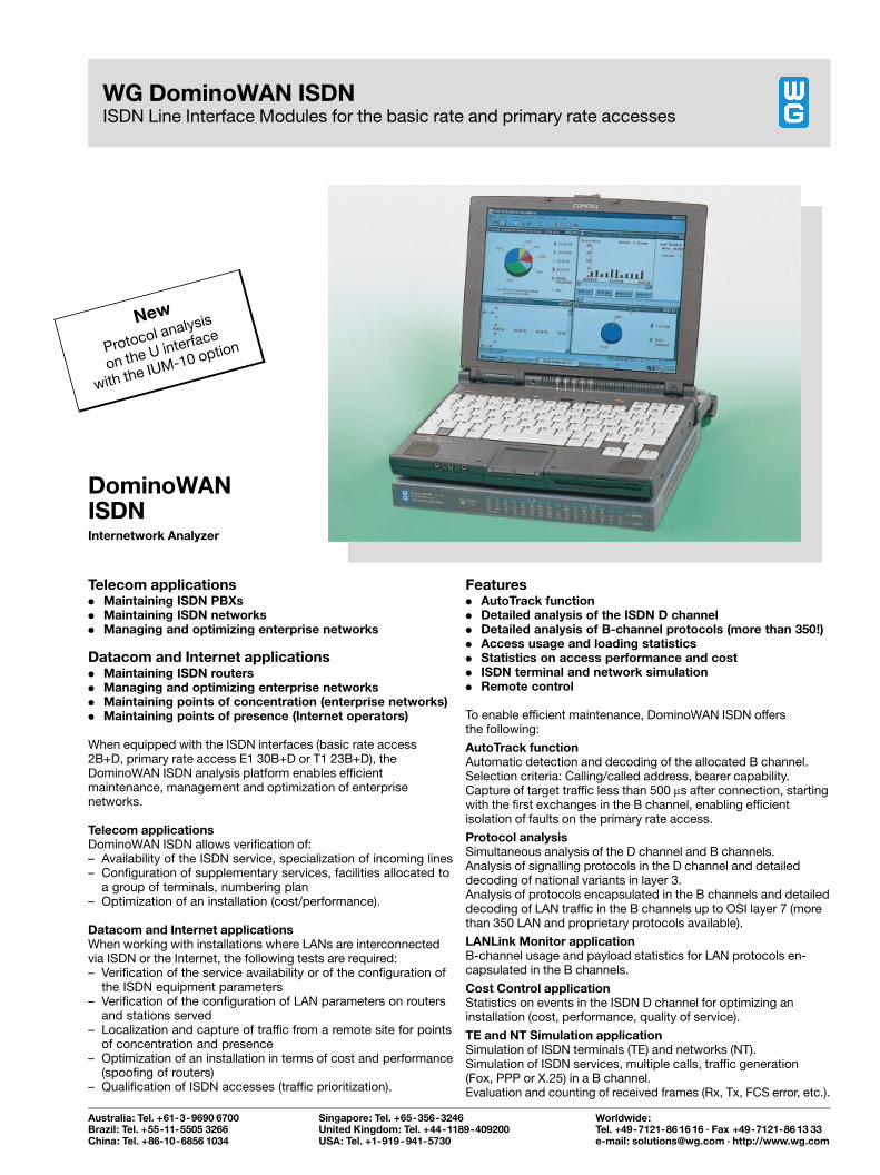
Telecom applications. Maintaining ISDN PBXs. Maintaining ISDN networks. Managing and optimizing enterprise networks
Datacom and Internet applications. Maintaining ISDN routers. Managing and optimizing enterprise networks. Maintaining points of concentration (enterprise networks). Maintaining points of presence (Internet operators)
When equipped with the ISDN interfaces (basic rate access2B+D, primary rate access E1 30B+D or T1 23B+D), theDominoWAN ISDN analysis platform enables efficientmaintenance, management and optimization of enterprisenetworks.
Telecom applicationsDominoWAN ISDN allows verification of:± Availability of the ISDN service, specialization of incoming lines± Configuration of supplementary services, facilities allocated to
a group of terminals, numbering plan± Optimization of an installation (cost/performance).
Datacom and Internet applicationsWhen working with installations where LANs are interconnectedvia ISDN or the Internet, the following tests are required:± Verification of the service availability or of the configuration of
the ISDN equipment parameters± Verification of the configuration of LAN parameters on routers
and stations served± Localization and capture of traffic from a remote site for points
of concentration and presence± Optimization of an installation in terms of cost and performance
(spoofing of routers)± Qualification of ISDN accesses (traffic prioritization).
Features. AutoTrack function. Detailed analysis of the ISDN D channel. Detailed analysis of B-channel protocols (more than 350!). Access usage and loading statistics. Statistics on access performance and cost. ISDN terminal and network simulation. Remote control
To enable efficient maintenance, DominoWAN ISDN offersthe following:
AutoTrack functionAutomatic detection and decoding of the allocated B channel.Selection criteria: Calling/called address, bearer capability.Capture of target traffic less than 500 ms after connection, startingwith the first exchanges in the B channel, enabling efficientisolation of faults on the primary rate access.
Protocol analysisSimultaneous analysis of the D channel and B channels.Analysis of signalling protocols in the D channel and detaileddecoding of national variants in layer 3.Analysis of protocols encapsulated in the B channels and detaileddecoding of LAN traffic in the B channels up to OSI layer 7 (morethan 350 LAN and proprietary protocols available).
LANLink Monitor applicationB-channel usage and payload statistics for LAN protocols en-capsulated in the B channels.
Cost Control applicationStatistics on events in the ISDN D channel for optimizing aninstallation (cost, performance, quality of service).
TE and NT Simulation applicationSimulation of ISDN terminals (TE) and networks (NT).Simulation of ISDN services, multiple calls, traffic generation(Fox, PPP or X.25) in a B channel.Evaluation and counting of received frames (Rx, Tx, FCS error, etc.).
DominoWANISDNInternetwork Analyzer
WG DominoWAN ISDNISDN Line Interface Modules for the basic rate and primary rate accesses
New
Protocol analysis
on the U interface
with the IUM-10 option
Australia: Tel. +61-3-9690 6700Brazil: Tel. +55-11-5505 3266China: Tel. +86-10-6856 1034
Singapore: Tel. +65-356-3246United Kingdom: Tel. +44-1189-409200USA: Tel. +1-919-941-5730
Worldwide:Tel. +49-7121-86 16 16 ´ Fax +49-7121-86 13 33e-mail: [email protected] ´ http://www.wg.com
Product Literature
25
Wandel & Goltermann
Communications Test Solutions
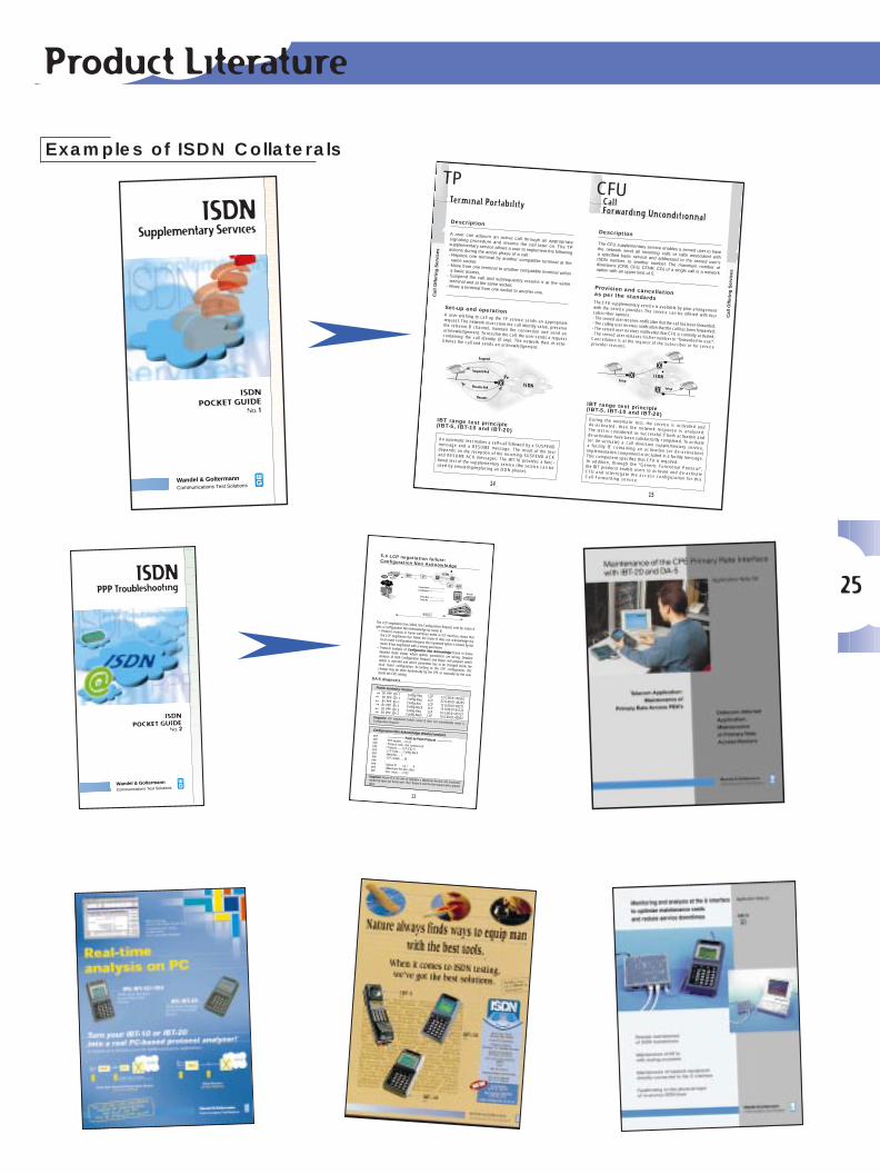
ISDNSupplementary Services
ISDN
POCKET GUIDENo. 1
1 5
I S DNSetup
Setup
Description
The CFU supplementary service enables a served user to havethe network send all incoming calls or calls associated witha specified basic service and addressed to the served user’sISDN number, to another number. The maximum number ofdiversions (CFB, CFU, CFNR, CD) of a single call is a networkoption with an upper limit of 5.
IBT range test principle(IBT-5, IBT-10 and IBT-20) During the automatic test, the service is activated andde-activated, then the network response is analyzed.The test is considered as successful if both activation andde-activation have been satisfactorily completed. To activate(or de-activate) a call diversion supplementary service,a facility IE containing an activation (or de-activation)implementation component is included in a facility message.This component specifies that CFU is required.In addition, through the “Generic Functional Protocol”,the IBT products enable users to activate and de-activateCFU and interrogate the access configuration for thisCall Forwarding service.
Call Forwarding Unconditionnal
CFU
Provision and cancellationas per the standardsThe CFU supplementary service is available by prior arrangementwith the service provider. The service can be offered with foursubscriber options: - The served user receives notification that the call has been forwarded;- The calling user receives notification that the call has been forwarded;- The served user receives notification that CFU is currently activated;- The served user releases his/her number to “forwarded-to user”.Cancellation is at the request of the subscriber or for serviceprovider reasons.
Cal
l Offe
ring
Ser
vice
s
➜
1 4
Cal
l Offe
ring
Ser
vice
s
➜
I S DN
Suspend
Suspend Ack
Resume Ack
Resume
Description
A user can adjourn an active call through an appropriatesignaling procedure and resume the call later on. The TPsupplementary service allows a user to implement the followingactions during the active phase of a call :- Replace one terminal by another compatible terminal at thesame socket,
- Move from one terminal to another compatible terminal withina basic access,
- Suspend the call and subsequently resume it at the sameterminal and at the same socket,- Move a terminal from one socket to another one.
IBT range test principle(IBT-5, IBT-10 and IBT-20)
Set-up and operationA user wishing to call up the TP service sends an appropriaterequest. The network must store the call identity value, preservethe relevant B channel, maintain the connection and send anacknowledgement. To resume the call, the user sends a requestcontaining the call identity (if any). The network then re-esta-blishes the call and sends an acknowledgement.
TP
An automatic test makes a self-call followed by a SUSPENDmessage and a RESUME message. The result of the testdepends on the reception of the incoming SUSPEND ACKand RESUME ACK messages. The IBT-10 provides a func-tional test of the supplementary service (the service can beused by emulating/replacing an ISDN phone).
Terminal Portability
Wandel & Goltermann
Communications Test Solutions
ISDNPPP Troubleshooting
ISDN
POCKET GUIDENo. 2
1 3
Config. RequestConfig. Request
Config. NackConfig. Ack
B channelPPP
LAN Router A
I S DN
Router B
PBX
LTNT1US/T
LT NT1
5.4 LCP negotiation failure: Configuration Non Acknowledge
The LCP negotiation has failed, the Configuration Request sent by router Agets a Configuration Non Acknowledge by router B.• Protocol analysis in frame summary mode at S/T interface shows that
the LCP negotiation has failed: the router B does not acknowledge thelocal router Configuration Request, the requested option is known by therouter B but negotiated with a wrong parameter.• Protocol analysis of Configuration Non Acknowledge frame in framedetailed mode shows which options parameters are wrong. Detailedanalysis of both Configuration Request and Reject will pinpoint whichoption is rejected and which parameter has to be changed inside thelocal router configuration. According to the CPE configuration, thischange may be done dynamically by the CPE or manually by the userinside the CPE setting.
Frame summary monitor
Diagnosis: LCP negotiation failure, router B does not acknowledge router AConfiguration Request.
➞ B1 PPP ID=1 Config-Req LCP 12 G 00:01:44262➥ B1 PPP ID=1 Config-Req LCP 22 G 00:01:44269➥ B1 PPP ID=1 Config-Ack LCP 12 G 00:01:44271➞ B1 PPP ID=1 Config-Nack LCP 14 G 00:01:45122➥ B1 PPP ID=2 Config-Req LCP 16 G 00:01:45127➞ B1 PPP ID=2 Config-Nack LCP 16 G 00:01:45832
➞➞
➞
PPP : ------------- Point-to-Point Protocol -------------PPP : PPP header..... FF 03PPP : Protocol code.. Not compressedPPP : Protocol....... LCP (C021)PPP : LCP Code....... Config-NackPPP : Identifier..... 1PPP : LCP Length..... 30PPP :PPP : Option 01 Lg = 4PPP : (Maximum-Receive-Unit)PPP : Dec. value...... 1522
Configuration Non Acknowledge detailed analysis
Diagnosis: Router B is not able to negotiate a Maximum-Receive unit (maximumnumber by bytes per frame) over 1522. Router A sent the first request with a greatervalue.
DA-5 diagnosis
➤
➤
Examples of ISDN Collaterals
Product Literature
26
WG IBT-5ISDN Tester for Basic Rate Access
For installation, first level of commissioning
and maintenance.
ISDN Tester/Analyzerfor Primary Rate Access
For installation, commissioning and maintenance.
WG IBT-20
WG IBT-10/-10UISDN Tester/Analyzerfor Basic Rate AccessFor installation, commissioning and maintenance.
ClosingFlag
FCS Information Control Address OpeningFlag
First bitTransmitted
1
1
2
3
etc.
➜
Octet
Octet8 7 6 5 4 3 2 1
0 0 0 0 1 0 0 0
8 7 6 5 4 3 2 1
0 0 0 0
Protocol discriminator
Lenght of call referencevalue (octets)
Call reference value (CRV)
Message type
Flag
Other information elements as required
Q.931 user-network call control messages
0
Protocol Discriminator
L.FL.DL.
L.FD L.ESDEMDE
L.FAL.DL.
NFAADE
NT to TE
48 bits in 250 microseconds
TE to NT
L.FL.D
t
B1 B1
B1B1
B2
B2
B2
B2
L.FL.D010
2 bits offset
L.DL.L.DL.
F = framing bitL = DC balancing bitD = D-channel bitE = D-echo-channel bit
N = bit set to a binary value N = FA (NT to TE)B1 = bit within B channel 1B2 = bit within B channel 2A = bit used for activation
FA = Auxiliary framing bitS = Reserved for future standardizationM = multiframing bit
FW / IFW 12 x (2B+D) CL
# BitsBits positions
2 B + DFWIFWCL
====
Customer data channels B1, B2 and DFrame WordInverted Frame WordM-channel bits, M1-M6
The CL channel (M bits) is a 4-kbit/s pipe designed to convey maintenance information over the local loop.This channel comprises:
- the EOC commands (Embedded Operations Channel) used by the LT to send operation commands to the NT1 (Loopback request, etc.),- a CRC information for each multi-frame sent, - other information such as Activation and Deactivation command and indications (ACT, SAI, DEA...), FEBE, etc.
181-18
21619-234
1,5 ms
6235-240
Physical
Handles the physical, electrical, and pro-cedural specifications required to transmitdata accross the physical medium or cables.Defines connectors, pinouts and electricalvoltage and current levels.Works in units of bits.
ETSI Message Structure
Network
Addresses, switches and routes pac-kets between hosts.Fragments and reassembles packets.Works in units of packets.
Hex 8 7 6 5 4 3 2 1 ETSI message type
Call establishment01 0 0 0 0 0 0 0 1 Alerting02 0 0 0 0 0 0 1 0 Call Proceeding03 0 0 0 0 0 0 1 1 Progress05 0 0 0 0 0 1 0 1 Setup07 0 0 0 0 0 1 1 1 Connect0D 0 0 0 0 1 1 0 1 Setup Acknowledge0F 0 0 0 0 1 1 1 1 Connect Acknowledge
Call Information Phase20 0 0 1 0 0 0 0 0 User Information21 0 0 1 0 0 0 0 1 Suspend Reject22 0 0 1 0 0 0 1 0 Resume Reject24 0 0 1 0 0 1 0 0 Hold25 0 0 1 0 0 1 0 1 Suspend26 0 0 1 0 0 1 1 0 Resume28 0 0 1 0 1 0 0 0 Hold Acknowledge2D 0 0 1 0 1 1 0 1 Suspend Acknowledge2E 0 0 1 0 1 1 1 0 Resume Acknowledge30 0 0 1 1 0 0 0 0 Hold Reject31 0 0 1 1 0 0 0 1 Retrieve33 0 0 1 1 0 0 1 1 Retrieve Acknowledge37 0 0 1 1 0 1 1 1 Retrieve Reject
Call Clearing45 0 1 0 0 0 1 0 1 Disconnect46 0 1 0 0 0 1 1 0 Restart4D 0 1 0 0 1 1 0 1 Release4E 0 1 0 0 1 1 1 0 Restart Acknowledge5A 0 1 0 1 1 0 1 0 Release Complete
Miscellaneous60 0 1 1 0 0 0 0 0 Segment62 0 1 1 0 0 0 1 0 Facility64 0 1 1 0 0 1 0 0 Register6E 0 1 1 0 1 1 1 0 Notify75 0 1 1 1 0 1 0 1 Status Enquiry79 0 1 1 1 1 0 0 1 Congestion Control7B 0 1 1 1 1 0 1 1 Information7D 0 1 1 1 1 1 0 1 Status
Hex 8 7 6 5 4 3 2 1 Information Element Identifier
Single octet information elements 1 0 0 0 - - - - Reserved 1 0 0 1 - - - - Shift 1 0 1 0 0 0 0 0 More Data 1 0 1 0 0 0 0 1 Sending Complete 1 0 1 1 - - - - Congestion Level 1 1 0 1 - - - - Repeat Indicator
Variable Length Information Elements00 0 0 0 0 0 0 0 0 Segmented Message04 0 0 0 0 0 1 0 0 Bearer Capability08 0 0 0 0 1 0 0 0 Cause10 0 0 0 1 0 0 0 0 Call Identity14 0 0 0 1 0 1 0 0 Call State18 0 0 0 1 1 0 0 0 Channel Identification1C 0 0 0 1 1 1 0 0 Facility1E 0 0 0 1 1 1 1 0 Progress Indicator20 0 0 1 0 0 0 0 0 Network-specific Facilities27 0 0 1 0 0 1 1 1 Notification Indicator28 0 0 1 0 1 0 0 0 Display29 0 0 1 0 1 0 0 1 Date/time2C 0 0 1 0 1 1 0 0 Keypad Facility34 0 0 1 1 0 1 0 0 Signal36 0 0 1 1 0 1 1 0 Switchhook38 0 0 1 1 1 0 0 0 Feature Activation39 0 0 1 1 1 0 0 1 Feature Indication40 0 1 0 0 0 0 0 0 Information Rate42 0 1 0 0 0 0 1 0 End-to-end Transit Delay43 0 1 0 0 0 0 1 1 Transit Delay Selection and Indication44 0 1 0 0 0 1 0 0 Packet Layer Binary Parameters45 0 1 0 0 0 1 0 1 Packet Layer Window Size46 0 1 0 0 0 1 1 0 Packet Size4C 0 1 0 0 1 1 0 0 Connected Party Number4D 0 1 0 0 1 1 0 1 Connected Party Sub-address6C 0 1 1 0 1 1 0 0 Calling Party Number6D 0 1 1 0 1 1 0 1 Calling Party Sub-address70 0 1 1 1 0 0 0 0 Called Party Number71 0 1 1 1 0 0 0 1 Called Party Sub-address74 0 1 1 1 0 1 0 0 Redirecting Number78 0 1 1 1 1 0 0 0 Transit Network Selection79 0 1 1 1 1 0 0 1 Restart Indicator7C 0 1 1 1 1 1 0 0 Low Layer Compatibility7D 0 1 1 1 1 1 0 1 High Layer Compatibility7E 0 1 1 1 1 1 1 0 User-user7F 0 1 1 1 1 1 1 1 Escape For Extension Other values Reserved
ETSI Information Element IdentifierLayer 3
Layer 2
Layer 1
C/R - Command/response field bitEA0 - Extented Address bit 0EA1 - Extented Address bit 1
ClosingFlag
FCS Information Control Address OpeningFlag
First bitTransmitted
2
3
Octet8 7 6 5 4 3 2 1
SAPI
TEI
C/R EA0
EA1
Commands from
Commands toResponses from
Responses to
Network SideC/R Value
User SideC/R Value
1 01 00 10 1
SAPI - Service Access Point Identifier 0 Call control procedures 1 Packet mode using Q.931Call procedures16 Packet communications conforming to X.25 Level 3 procedures63 Layer 2 Management proceduresAll others reserved for future use
TEI - Terminal Endpoint Identifier 0 - 63 Fixed TEI assignment 64-126 Automatic TEI assignment 127 Group TEI for broadcast data link connection
ClosingFlag
FCS Information Control Address OpeningFlag
First bitTransmitted
InformationTransfer
I(information)
N(S)N(R)
OP
----
0 10 0 0 0 0 0
0 10 0 0 0 1 0
0 10 0 0 1 0 0
RR(receive ready) N(R) P/F
01
Unnumbered
SABME(setasynchronousbalanced mode
extended)
DISC(disconnect)
0 11 1 P 1 1 1 6F/7F
0 10 0 F 1 1 1 0F/1F
0 11 0 P 0 0 1 43/53
--
Supervisory RNR(receive not ready) N(R) P/F
05
--
REJ(reject)
RR(receive ready)
RNR(receive not ready)
REJ(reject)
DM(disconnected
mode)
N(R) P/F
09
--
UI(unnumberedInformation)
0 10 0 P 0 0 1 03/13
XID (ExchangeIdentification)
XID (ExchangeIdentification)
0 11 1 F 0 0 1 63/73
FRMR(frame reject) 1 10 0 F 0 1 1 87/97
1 10 1 P/F 1 1 1 AF/BF
454
4
4
4
54545
4
4
4
4
Format Commands Responses Binary ConfigurationHex
Config.8 17 6 5 4 3 2
UA(unnumbered
acknowledgement)
Octet
Q.921 Address Field Q.921 Control Field
CustomerPremises
Transmission Line
Terminals PBX
2 wires4 wires
CentralOffice
TE 2 TA
TE 1 NT 2S
S
NT 1 LT ISDN switch
ISDN switch
Packet-switched capabilities
Bearer capabilities
User-user signaling
User-networksignaling
Circuit-switched capabilities
Nonswitched capabilities
Common-channel signaling capabilities
T U
R
Line Termination (LT)
Network Termination 1 (NT1): handles physical layer interface functionssuch as line termination, power transfer and timing.
Network Termination 2 (NT2): handles function of an NT1 plus layer 2and layer 3 functions such as multiplexing, switching and concentration.
Terminal Equipment 1 (TE1): end user equipment such as ISDNtelephones or data terminals compliant with ISDN call set up procedures and capable of interfacing directly to the S-bus.
Terminal Equipment 2 (TE2): end user equipment for non ISDN environments (typically uses an RS232 interface).
Terminal Adapter (TA): equipment that supports ISDN call set up and provides an interface for connecting to TE2s.
ISDN Functional Groups and Reference Points
Guide to
architectureISDN
ISDNprotocols
ClosingFlag
CRC Control
Octet
Message Name Management entity identifier
Referencenumber Ri
Message Type Action indicator Ai
1 2 3 4
Address OpeningFlag First bit
Transmitted
Identity request(user to network)
Identity assigned(network to user)
Ai = 127, Any TEI value acceptable0000 1111 0000 00010-65535
Identity check response(user to network)
Ai = 0, TEI value in use0000 1111 0000 01010-65535
Identity verify(user to network)
Ai = 0-126, TEI value to be checked0000 1111 0000 0111Not used (coded 0)
Ai = 64-126, Assigned TEI value0000 1111 0000 00100-65535
Identity denied(network to user)
Ai = 64-126, denied TEI valueAi = 127, No TEI value available
0000 1111 0000 00110-65535
INFO UI TEI=127 SAPI=63
Identity check request(network to user)
Ai = 127, Check all TEI valuesAi = 0-126, TEI value to be checked
0000 1111 0000 0100Not used (coded 0)
Identity remove(network to user)
Ai = 127, Request for removal of all TEI valuesAi = 0-126, TEI values to be removed
0000 1111 0000 0110Not used (coded 0)
Frame Structure for TEI Management
ETSI Message Type
ETSI Cause V
Handset Ringba
Disconnect
Make a Phone Cby Lifting the H
Install the Phon
ISDN Test Solut
Frame Structure at S and T Reference Points Frame Structure at U Reference Point
7 Application Layer6 Presentation Layer5 Session Layer4 Transport Layer3 Network Layer2 Data Link Layer1 Physical Layer
I.430BasicRate
I.431PrimaryRate
Q.921 (LAPD)D Channel link layer
Q.931Call Setup proceduresover the D Channel
1 01 81 Unallo2 02 82 No rou3 03 83 No rou6 06 86 Chann7 07 87 Call aw16 10 90 Norma17 11 91 User b18 12 92 No use19 13 93 No ans21 15 95 Call rej22 16 96 Numbe26 1A 9A Non-se27 1B 9B Destina28 1C 9C Invalid29 1D 9D Facility30 1E 9E Respo31 1F 9F Norma34 22 A2 No circ38 26 A6 Netwo41 29 A9 Tempo42 2A AA Switch43 2B AB Access44 2C AC Reque47 2F AF Resou49 31 B1 Quality50 32 B2 Reque53 35 B5 Outgoi55 37 B7 Incom57 39 B9 Bearer58 3A BA Bearer63 3F BF Service65 41 C1 Bearer66 42 C2 Chann69 45 C5 Reque70 46 C6 Only re79 4F CF Service81 51 D1 Invalid82 52 D2 Identif83 53 D3 A susp84 54 D4 Call ide85 55 D5 No cal86 56 D6 Call ha88 58 D8 Incom90 5A DA Non-ex91 5B DB Invalid95 5F DF Invalid96 60 E0 Manda97 61 E1 Messa98 62 E2 Messa non-ex99 63 E3 Inform100 64 E4 Invalid101 65 E5 Messa102 66 E6 Recove111 6F EF Protoc127 7F FF Interw Other values Reserv
Hex.Bit 8=1Dec Hex.
OSI Model
ISDN Implementation
Data link
Frames and Addresses Packets.Provides error-free node-to-nodeconnections and flow control.Provides mapping between NetworkLayer addresses.Works in units of frames.
Testers
http://isdn.wg.com
ISDN/LAN Cable TesterFor installation,
commissioning and maintenance ofstructured cabling at customer premises.
NEWNEW
SOFTWAREDOWNLOAD
VIA V.24
SOFTWAREDOWNLOAD
VIA V.24
WG IST-15
‘Guide to ISDN Test Solutions’ Poster
27
A closely linked network of more than 25 affiliated companies and more than 65 agencies around the world ensures that you receive
the best possible advice in solving specific test problems. For more detailed information, please turn to your local sales agency.
Internetwork Analyzer for Basic RateAccess and Primary Rate Access
For monitoring and troubleshootingof ISDN access and LAN
interconnection over ISDN.
And also DA-30 ISDN,Internetwork Analyzer for Lab applications.
DominoWAN ISDN
DominoWAN ISDNDA-30 ISDN
Multiport Protocol AnalyzerFor fault detection and maintenance
of datacommunicationsover WAN and ISDN
Basic Rate Access.
WG DA-5
Octet Hex 8 7 6 5 4 3 2 1 Information element
1 0 0 0 0 0 1 0 0 Bearer capability2 0 0 0 0 Length of Bearer capability (max. 13 octets)3 1
Coding standard 0 0 CCITT standardized coding as decribed below
Information transfer capability 80 0 0 0 0 0 Speech 88 0 1 0 0 0 Unrestricted digital information 89 0 1 0 0 1 Restricted digital information 90 1 0 0 0 0 3,1 kHz audio 91 1 0 0 0 1 7 kHz audio4 0/1
Transfer mode 0 0 Circuit mode 1 0 Packet mode
Information transfer rate 40/C0 1 0 0 0 0 0 0 Packet mode call 10/90 0 0 1 0 0 0 0 64 kbit/s 11/91 0 0 1 0 0 0 1 2 x 64 kbit/s 13/93 0 0 1 0 0 1 1 384 kbit/s 15/95 0 0 1 0 1 0 1 1536 kbit/s 17/97 0 0 1 0 1 1 1 1920 kbit/s
Octet Hex 8 7 6 5 4 3 2 1 Information element1 7D 0 1 1 1 1 1 0 1 High Layer compatibility2 0 0 0 0 0 . . . Length of High Layer compatibility (max. 5 octets)3 1
Coding standard 0 0 CCITT standardized coding as decribed below
Interpretation 1 0 0 First high layer charact. identif. to be used in the call
Presentation method of protocol profile91 0 1 High layer protocol profile (without spec. of attribut.)
4 0/1High layer characteristics identification
01/81 0 0 0 0 0 0 1 Telephony04/84 0 0 0 0 1 0 0 Facsimile Group 2/3 (Rec. F.182)21/A1 0 1 0 0 0 0 1 Facsimile Group 4 Class.1 (Rec. F.184)24/A4 0 1 0 0 1 0 0 Teletex service (F.230) and Fac. Cl. II and III28/A8 0 1 0 1 0 0 0 Teletex service (F.220)31/B1 0 1 1 0 0 0 1 Teletex service (F.200)32/B2 0 1 1 0 0 1 0 Syntax based Videotex (Rec. F.300 and T.102)33/B3 0 1 1 0 0 1 1 Int. Videotex Interworking (Rec. F.300 and T.101)35/B5 0 1 1 0 1 0 1 Telex service (Rec. F.60)38/B8 0 1 1 1 0 0 0 Message Handling System (X.400 series)41/C1 1 0 0 0 0 0 1 OSI application (X.200 series)60/E0 1 1 0 0 0 0 0 Audiovisual = Videoteleph., (Rec. F.721 and AV.242)
Number Identification Services
Call Offering Services
Community of Interest and Call Restriction Services
MSN Multiple Subscriber NumberDDI Direct Dial InSUB Sub AddressCLIP Calling Line Identification PresentationCLIR Calling Line Identification RestrictionCOLP Connected Line Identification PresentationCOLR Connected Line Identification Restriction
TP Terminal PortabilityCFU Call Forwarding UnconditionalCFB Call Forwarding BusyCFNR Call Forwarding No Reply
CW Call Waiting HOLD Call Hold
Call Completion Services
Charging Services
Additional Transfer Information UUS User to User SignalingServices
CUG Closed User Group
AOC-S Advice of charge at setup timeAOC-D Advice of charge during the callAOC-E Advice of charge at end of call
SETUPSAPI=0
CONNECT Bi
SAPI=0
CALL
DATA
CALL CONF
To the X.25 gateway
BC = unrestricted dataCLD = X.25 gatewayCHI = B channel onlyD
B
SETUPSAPI=0
CONNECT Bi
SAPI=0
CALL
DATA
CALL CONF
To the nearest Packet Handler
BC = Packet BearerCLD = not presentCHI = Any B channel
ISDN network is not informed of the B channel content.Multiplex is not possible
D
B
SETUPSAPI=0
SAPI=0
CONNECT D
SAPI=0
SAPI=16
DISCONNECT
SAPI=16
CALL
DATASAPI=16
CALL CONFCLD = X.25 address
CAUSE = 07
BC = Packet BearerCLD = not presentCHI = D channel only
BC = Bearer capabilityCLD = Called addressCHI = Channel identification
ISDN network can multiplex X.25 connection in the first switch.
ISDN network can multiplex X.25 connection in the first switch.
D
Bearer services
Teleservices
X.25 PacketBearer mode
Supplementaryservices
Wandel & GoltermannCommunications Test Solutions
WorldwideWandel&Goltermann
CustomerPremises
Transmission Line
CentralOffice
TE 1NT 1U S
LT
ISDNservices
Value
North AmericaCanada: Tel. +1-416 291 7121
USA: Tel. +1-919 941 5730Mexico: Tel. +52-5 543 6644
Latin AmericaGuatemala/Central America/Caribbean Islands:
Tel. +502-3 31 80 65Brazil/Chile/Peru/Bolivia/Paraguay:
Tel. +55-11-5505 3266Argentina: Tel. +54-1-784 4700
AsiaChina: Tel. +86-10 6856 1034
India: Tel. +91-11 619 5358Singapore: Tel. +65-356 3246
Australia/Pacific Islands/New Zealand:Tel. +61-39 690 6700
EuropeAustria: Tel. +43-22 52 85 521-0
France: Tel. +33-1 30 81 50 50Germany: Tel. +49-7121 98 56 10
Italy: Tel. +39-2 895 12381Spain/Portugal: Tel. +34-91 383 9801
Sweden: Tel. +46-8 449 48 00United Kingdom: Tel. +44-1189 409200
Switzerland: Tel. +41-31-991 7781Benelux: Tel. +31-40-267 9700
For all other countries:Fax: 49-7121 86 13 33
email: [email protected]: //isdn.wg.com
Activate Layer 1
UI (ID Request)
UI (ID Assign)
SABME
UA
I (SETUP)
I (Alert)
I (CONN)
I (CONN.ACK.)
Activate Layer 1
UI (SETUP)
UI (ID Request)
UI (ID Assign)
SABME
UA
I (Alert)
I (CONN)
I (CONN.ACK.)
B-Channel Connection
I (DISC)
I (REL)
I (REL COMP)
DISC
UA
Deactivate Layer 1
I (DISC)
I (REL)
I (REL COMP)
DISC
UA
Deactivate Layer 1
Address CompleteMessage (ACM)
Release Message(REL)
Release CompleteMessage (REL)
Initiate ActivateMessage (IAM)
ack Phone Ring
Answer the Phone
CallHandset
Answer Message(ANM)
ne
ISDNCPE
ISDNSwitch
ISDNSwitch
ISDNCPE
ETSI Call ControlProcedure
tionsAnalyzers
cated (unassigned) numberute to specified transit networkute to destinationel unacceptable
warded and being delivered in an established channelal call clearingbusyer respondingswer from user (user alerted)jecteder changedelected user clearingation out of order
d number formaty rejectednse to "Status enquiry"
al, unspecifiedcuit/channel availablerk out of order
orary failurehing equipment congestions information discardedsted circuit/channel not availablerces unavailable, unspecifiedy of service unavailablested facility not subscribeding calls barred within CUGing calls barred within CUG
r capability not authorizedr capability not presently availablee or option not available, unspecifiedr capability not implementedel type not implementedsted facility not implementedestricted digital information bearer capability is availablee or option not implemented, unspecified
d call reference valueied channel does not exist
pended call exists, but this call identity does not existentity in usel suspended
aving the requested call identity has been clearedpatible destinationxistent CUG
d transit network selectiond message, unspecifiedatory information element is missingage type non-existent or not implementedage not compatible with call state or message typexistent or not implemented
mation element/parameter non-existent or not implementedde information element contentsage not compatible with call stateery on timer expiry
col error, unspecifiedorking, unspecifiedved
Cause Name
Functional Group Reference Point
X.31 case A
X.31 case B - X.25/B
X.31 case B - X.25/D
ISDN U-Interface MonitorConnection of any ISDN BRA protocol analyzer to
the U interface for the maintenance of ISDNlines and equipment from any site along the
local loop: access, repeater or central office.
WG IUM-10
- Prin
ted
in F
ranc
e
E
9.9
8/W
G2/2
08/1
0/4c
E D I T I O N 2E D I T I O N 2
Real-time expertise withpossible storage
on hard diskfor long-term
measurement.Report editing after
ISDN service turn-up.
WindowsTM PCDetailed Decoder
NEWNEW
NEWNEW
Enter ISDN technology with Wavetek WandelGoltermann! The ISDN technology has reachedan advanced level and Wavetek WandelGoltermann now offers a complete range of ISDNtest solutions.In order to help you better understand ISDN protocols and services, Wavetek WandelGoltermann has designed a pedagogical postercalled 'Guide to ISDN Test Solutions'.
Visit our Website to get a free copy:http://www.wg.com/isdnposter.html.

A closely linked network of 29 affiliated companies and more than 65 representatives
ensures that our customers receive the best possible advice in solving specific measurement problems.
For all contacts in Western Europe:Wandel & Goltermann GmbH & Co.
Vertriebsgesellschaft PO Box 1155
72794 ENINGEN u.A. - GERMANYTel: +49 7121 9856 10Fax: +49 7121 9856 12
For all contacts in Eastern Europe:Wandel & Goltermann GmbH
Postfach 13Elisabethstraße 36
A-2500 Baden - AUSTRIATel: +43 2252 85521 0
Fax: +43 2252 80727
For all contacts in North America:Wandel & Goltermann Inc.
PO Box 135851030 Swabia Court
Research Triangle ParkNC 27709-3585 - USATel: +1 919 941 5730Fax: +1 919 941 5751
For all contacts in Asia/Pacific:Wandel & Goltermann Pty. Ltd.
PO Box 419World Trade Centre
MelbourneVictoria 3005 - AUSTRALIA
Tel: +61 3 690 6700Fax: +61 3 690 6750
For all contacts in Latin America:Wandel & Goltermann
Instrumentaçao Ltda. & Cia.Av. Eng. L. Carlos Berrini
936-9 Andar04571-000 São Paulo, SP
BRAZILTel: +55 11 5503 3800Fax: +55 11 5505 1598
For any further informationor to get the address
of your local Sales Office,please contact
Wavetek Wandel Goltermann at the following address:
Wandel & Goltermann GmbH & Co.Marketing International
PO Box 1262D - 72795 ENINGEN u.A.
GERMANYTel: +49 7121 86 1616Fax: +49 7121 86 1333
Or have a look at the WG Web site:http://www.wg.com
email: [email protected]
WorldwideWavetek WandelGoltermann
Edited and coordinated by:Wandel & Goltermann CTSMarketing DepartmentRennes, France
Layout:Soleil Rouge, Rennes
Order no.E 3.99/D2/1606/10
All rights reserved.March 1999
Your contact