Embed Size (px)
Citation preview
Application about Communication
WAN Access Method Communication via Analog Dial In/Out Ethernet-Router
Configuration Example

Warranty, liability and support
Dial in/out Routers (analog) 26662448
V1.0 08/06/07 2/54
Cop
yrig
ht ©
Sie
men
s A
G 2
007
All
right
s re
serv
ed
2666
2448
_Ana
log_
PST
N_E
ther
net_
Rou
ter_
V1.
0_e.
doc
Note Applications are not binding and do not claim to be complete regarding the circuits shown, equipping and any eventuality. Applications do not represent customer-specific solutions. They are only intended to provide support for typical applications. You are responsible for ensuring that the described products are correctly used. These Applications do not relieve you of the responsibility of safely and professionally using, installing, operating and servicing equipment. When using this Application, you recognize that Siemens cannot be made liable for any damage/claims beyond the liability clause described. We reserve the right to make changes to these Applications at any time without prior notice. If there are any deviations between the recommendations provided in these Applications and other Siemens publications – e.g. Catalogs – then the contents of the other documents have priority.
Warranty, liability and support
We do not accept any liability for the information contained in this document.
Any claims against us – based on whatever legal reason – resulting from the use of the examples, information, programs, engineering and performance data etc., described in this example shall be excluded. Such an exclusion shall not apply in the case of mandatory liability, e.g. under the German Product Liability Act (“Produkthaftungsgesetz”), in case of intent, gross negligence, or injury of life, body or health, guarantee for the quality of a product, fraudulent concealment of a deficiency or breach of a condition which goes to the root of the contract (“wesentliche Vertragspflichten”). However, claims arising from a breach of a condition which goes to the root of the contract shall be limited to the foreseeable damage which is intrinsic to the contract, unless caused by intent or gross negligence or based on mandatory liability for injury of life, body or health. The above provisions do not imply a change in the burden of proof to your detriment.
Copyright© 2007 Siemens A&D. It is not permissible to transfer or copy this Application or excerpts of it without first having prior authorization from Siemens A&D in writing.
For questions about this document please use the following e-mail address:
mailto:[email protected]

Foreword
Dial in/out Routers (analog) 26662448
V1.0 08/06/07 3/54
Cop
yrig
ht ©
Sie
men
s A
G 2
007
All
right
s re
serv
ed
2666
2448
_Ana
log_
PST
N_E
ther
net_
Rou
ter_
V1.
0_e.
doc
Foreword Applications are functional and tested automation configurations based on A&D standard products and non-Siemens products for easy, fast and inexpensive implementation of automation tasks. Each of these Applications covers a frequently occurring subtask of a typical customer problem.
The Application helps you obtain answers to the following questions: Which products are required for these subtasks? How do they function when combined? To answer these questions, a tested example application is provided.
However, depending on the plant requirements, a variety of other components (e.g. other CPUs, power supplies, etc.) can be used to implement the functionality on which this Application is based. For these components, please refer to the corresponding SIEMENS A&D catalogs.
Reference to Automation and Drives Service & Support This entry is from the internet application portal of Automation and Drives Service & Support. Clicking the link below directly displays the download page of this document.
http://support.automation.siemens.com/WW/view/en/26662448
Series of documentations on “WAN access methods” This application is part of a series of documentations on “WAN access methods”. This series consists of:
• An application describing WAN access using analog Ethernet dial in / out routers, this document;
• an application on WAN access using port forwarding;
• an application on WAN access using VPN connections;
• an overview document providing ordering help
which are successively developed.

Foreword
Dial in/out Routers (analog) 26662448
V1.0 08/06/07 4/54
Cop
yrig
ht ©
Sie
men
s A
G 2
007
All
right
s re
serv
ed
2666
2448
_Ana
log_
PST
N_E
ther
net_
Rou
ter_
V1.
0_e.
doc
Table of Contents
Table of Contents ......................................................................................................... 4
1 Fields of Application and Benefits ........................................................... 5
2 Fundamental technical Principles ............................................................ 9
2.1 Router .............................................................................................................. 9
2.2 Dial in/out router ........................................................................................... 11
3 Configuration............................................................................................ 14
3.1 Hardware configuration ............................................................................... 14
3.2 Software requirements................................................................................. 16
4 Required Hardware and Software Components.................................... 17
5 Configuration and Startup of the Example ............................................ 18
5.1 INAT echoroute router configuration.......................................................... 18 5.1.1 Hardware configuration................................................................................... 19 5.1.2 Basic module configuration............................................................................. 20 5.1.3 Parameterizing the router functionality ........................................................... 25 5.1.4 Setting modem dialing parameters ................................................................. 30 5.1.5 Completing the configuration .......................................................................... 31
5.2 Westermo ZR-200 router configuration ...................................................... 32 5.2.1 Hardware configuration................................................................................... 33 5.2.2 Basic module configuration............................................................................. 34 5.2.3 Opening the parameterization menu .............................................................. 35 5.2.4 Parameterizing the router functionality ........................................................... 37
5.3 Network settings on the PC ......................................................................... 40
5.4 Network settings on the controller ............................................................. 42
5.5 Using dial-up connections from the workstation PC ................................ 43 5.5.1 Creating a dial-up connection ......................................................................... 43 5.5.2 Adjusting the dial-up connection settings ....................................................... 49 5.5.3 Setting the online interface for STEP 7........................................................... 51
6 Performance Data .................................................................................... 52
6.1 Constraints.................................................................................................... 52
6.2 Experiences from the application ............................................................... 52
7 History....................................................................................................... 54

Fields of Application and Benefits
Dial in/out Routers (analog) ID Number:
V1.0 08/06/07 5/54
Cop
yrig
ht ©
Sie
men
s A
G 2
007
All
right
s re
serv
ed
2666
2448
_Ana
log_
PST
N_E
ther
net_
Rou
ter_
V1.
0_e.
doc
1 Fields of Application and Benefits
Automation problem Remote access to an automation system (SIMATIC S7 or SIMOTION) is to be realized via Ethernet.
The following is to be possible:
• PG functions (with SIMATIC S7, HMI systems, SIMOTION, etc.) with
– diagnostic functions,
– remote programming and
– remote maintenance.
• Standard Ethernet communication services such as SEND / RECEIVE, FTP and HTTP accesses.
The data is accessed via a dial-up connection by means of a public PSTN/ISDN network.
Both communication partners are to be capable of actively establishing the dial-up connection.
The number of logical connections via the dial-up connection is solely limited by the transmittable bandwidth.
The data link is to be secured by a password and “call back” respectively.
Fields of Application and Benefits
Dial in/out Routers (analog) ID Number:
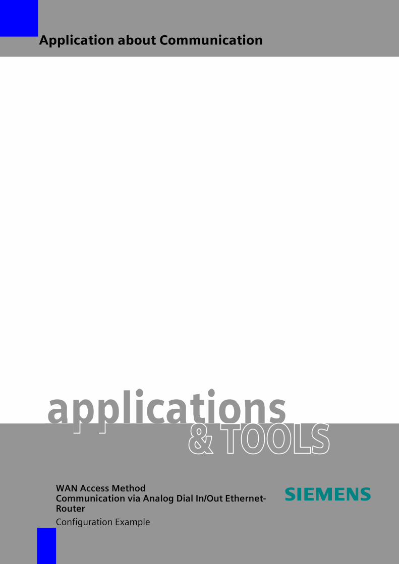
Automation solution The diagrammatic approach shown in the figure below is applied: Figure 1-1
V1.0 08/06/07 6/54
Cop
yrig
ht ©
Sie
men
s A
G 2
007
All
right
s re
serv
ed
2666
2448
_Ana
log_
PST
N_E
ther
net_
Rou
ter_
V1.
0_e.
doc
PSTN / ISDNtelephone network
IP network B
Recommendedminimum configuration:1 telephone analog line
Recommendedminimum configuration:1 telephone analog line
Applications•STEP 7•SIMOTION SCOUT•HTTP browser•FTP client
PG
S7-300
SIMOTION D
…
IP network A
PC S7-300/400 SIMOTION D
…
Dial in/outrouter
Dial in/outrouter
Modem
PG / PCwith int./ext.modem
The approach described in this application is based on the connection between two Ethernet networks via a dial-up connection and Ethernet dial in/out routers. The dial in/out routers establish the connection.
During establishing the connection, access security is ensured by
• authentication by a password or
• call back function.
After the connection between the routers has been established, the data is transferred via the dial-up connection using PPP.
The minimum requirement for such a dial-up connection is an analog telephone line; alternatively, a digital ISDN B channel can be used.

Fields of Application and Benefits
Dial in/out Routers (analog) ID Number:
V1.0 08/06/07 7/54
Cop
yrig
ht ©
Sie
men
s A
G 2
007
All
right
s re
serv
ed
2666
2448
_Ana
log_
PST
N_E
ther
net_
Rou
ter_
V1.
0_e.
doc
The two IP networks connected to the corresponding routers require different network addresses. The connected nodes use the respective network addresses and the local routers as a default gateway.
Alternative direct PC access via modem As an alternative to using a dial in/out router for the access, it is also possible to dial into the destination network via an analog modem that is connected directly to the PC. This requires that a dial-up network is set up that includes the settings of the calling router.
Fields of application This application is particularly suitable for use in fields of application for which no broadband connection is available. The penetration of DSL or other broadband networks is limited.
Analog telephone lines, however, can be used almost worldwide. Systems of this type are also capable of supporting the entire IP communication range.
This includes
• PG functions for STEP 7 and SIMOTION SCOUT,
• FTP communication,
• HTML accesses and
• Internet access (with restrictions).

Fields of Application and Benefits
Dial in/out Routers (analog) ID Number:
V1.0 08/06/07 8/54
Cop
yrig
ht ©
Sie
men
s A
G 2
007
All
right
s re
serv
ed
2666
2448
_Ana
log_
PST
N_E
ther
net_
Rou
ter_
V1.
0_e.
doc
Benefits The use of this application enables the customer to easily and cost-effectively access the data of a plant within the scope of a maintenance or commissioning from anywhere in the world with little work.
Timer-oriented data transfers, e.g. shift or daily operation data, with smaller data volumes between plants are also possible.
Constraints Due to the restriction of the uplink and downlink bandwidth of the dial-up connection, not every application is possible. Limitations are already to be expected when operated with small to medium data loads.
Applications via this communication medium must not have requirements concerning response times, times of 0.2 seconds per message are possible even when the distances are small.

Fundamental technical Principles
Dial in/out Routers (analog) ID Number:
2 Fundamental technical Principles
Introduction The following sections provide a brief explanation of the router functions on which this application is based.
2.1 Router
Definition A router is a device, normally a network component, that couples several networks. A router routes between different networks using the Layer 3 information of the protocol to be transmitted.
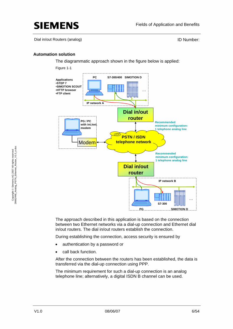
Mode of operation The figure below shows the mode of operation of a router:
V1.0 08/06/07 9/54
Cop
yrig
ht ©
Sie
men
s A
G 2
007
All
right
s re
serv
ed
2666
2448
_Ana
log_
PST
N_E
ther
net_
Rou
ter_
V1.
0_e.
doc Figure 2-1
ISO/OSI reference model
1
2
3
4
5
6
7
Laye
r
1
2
3
1
2
1
2
3
4
5
6
7
Node 1 Node 2
Router
IP network A IP network B
Routing table
Fundamental technical Principles
Dial in/out Routers (analog) ID Number:
V1.0 08/06/07 10/54
Cop
yrig
ht ©
Sie
men
s A
G 2
007
All
right
s re
serv
ed
2666
2448
_Ana
log_
PST
N_E
ther
net_
Rou
ter_
V1.
0_e.
doc
As described in the definition, the router routes between different subnets. The IP destination address of the data packet (part of the ISO/OSI reference model Layer 3) is used for routing. By means of the subnet ID, the router detects to which subnet the packet belongs and transmits it if necessary. The data of the actual packet is not changed. A directory of the different subnets, their subnet IDs and where they can be accessed are stored in the routing table.
This principle enables a cross-network control of the complete communication between nodes.
Different network interfaces (Layer 1 ISO/OSI reference model) Routers are available with different network interfaces.
The interfaces that can be used include:
• Ethernet
• Apple Talk
• PSTN / ISDN
• ATM
• …
The data switching principle is identical.
Ethernet routers are used in this application.

Fundamental technical Principles
Dial in/out Routers (analog) ID Number:
2.2 Dial in/out router
Functional scope A dial in/out router has the same range of functions as an Ethernet router (see chapter 2.1) and has an interface for connecting an Ethernet network. As a second interface, the dial in/out router additionally has a PSTN or ISDN interface for using the telephone network as an intermediate network.
Mode of operation The figure below schematically shows the mode of operation of a dial in/out router:
Figure 2-2
V1.0 08/06/07 11/54
Cop
yrig
ht ©
Sie
men
s A
G 2
007
All
right
s re
serv
ed
2666
2448
_Ana
log_
PST
N_E
ther
net_
Rou
ter_
V1.
0_e.
doc
1
2
3
4
5
6
7
Laye
r
1
2
3
1
2
1
2
3
4
5
6
7
Node 1 Node 2
Dial in/out router
Ethernet IP network A Ethernet IP network B
3
1
2
1
2
Dial in/out router
PSTN / ISDN network
Routing table Routing table
EthernetEthernet
As shown in the representation, a dial-up connection via a telephone network is used as an intermediate network between the two routers. Depending on the number of connected cable channels, dial in/out routers can use one or several connection(s) simultaneously. A dial-up connection can be established between two individual nodes or between entire networks. Ethernet packets of the Internet Protocol are handled as in standard Ethernet routers.
Aside from the IP subnet information, the routing table used in the routers includes the telephone number assigned to the subnet via which the network can be accessed by the router.

Fundamental technical Principles
Dial in/out Routers (analog) ID Number:
V1.0 08/06/07 12/54
Cop
yrig
ht ©
Sie
men
s A
G 2
007
All
right
s re
serv
ed
2666
2448
_Ana
log_
PST
N_E
ther
net_
Rou
ter_
V1.
0_e.
doc
Advantages of this method The main advantage of using dial in/out routers is that the method is universally applicable.
• A telephone connection is available almost anywhere in the world; thus the most important application requirement for using the dial in/out router is met.
• Routers of this type can be accessed from a standard analog modem via both a second router and a dial-up connection.
• The data communication is independent of the internet since switched dial-up connections are used for the communication.
• Different authentication mechanisms can be used to secure the connection establishment between the routers.
Constraints of this method The data bottleneck of such a transmission is the communication link with the lowest data throughput. When using dial in/out routers, this is the dial-up connection via the analog telephone network or the ISDN channel.
These two connection types achieve the following data throughput rates: Table 2-1
Connection type Max. / typ. data throughput
Analog telephone line Max. 56.5Kbps downstream / 48Kbps upstream (V.92)typ. 33.6Kbps upstream / downstream (V.34bis*)
ISDN B channel Max. 2 B channels 128Kbps upstream / downstream typ. 1 B channel 64Kbps upstream / downstream
*the bis ending: Defined by the ITU-TS, 2nd version of the previously named standard. (“terbo” defines the 3rd version)
Delay due to connection establishment Aside from the reduced data throughput, the duration of the connection establishment has to be observed when using the dial in/out routers. Between 2 routers, it may take a few seconds (for ISDN) or up to 30 seconds (for an analog telephone line).

Fundamental technical Principles
Dial in/out Routers (analog) ID Number:
V1.0 08/06/07 13/54
Cop
yrig
ht ©
Sie
men
s A
G 2
007
All
right
s re
serv
ed
2666
2448
_Ana
log_
PST
N_E
ther
net_
Rou
ter_
V1.
0_e.
doc
Alternative dial in/out routers The following table includes a selection of further possible dial in/out routers:
Table 2-2
Manufacturer Product name Link
Deltalogic Alarm Modem 56k http://www.deltalogic.deINSYS MoRoS http://www.insys-tec.de
MB Connect Line GmbH 500 / 600 series http://www.mbconnectline.deNetopia R2000 analog router http://www.netopia.com
Träger Industry Components TELE-PROF II http://www.traeger.deWestermo ED 10 (predecessor model:
ZR-200) http://www.westermo.de

Configuration
Dial in/out Routers (analog) ID Number:
3 Configuration
3.1 Hardware configuration
Overview The figure below shows the hardware configuration of this application.
Figure 3-1
V1.0 08/06/07 14/54
Cop
yrig
ht ©
Sie
men
s A
G 2
007
All
right
s re
serv
ed
2666
2448
_Ana
log_
PST
N_E
ther
net_
Rou
ter_
V1.
0_e.
doc
Modem
I/O
OH AA RD TD TR CD CS EC DC V34 K 56FAX MSG MR
K56FLE X
PSTN / ISDNtelephone network
IP network B
Usedconfiguration:1 telephone, analog line
Usedconfiguration:1 telephone, analog line
Applications•STEP 7•SIMOTION SCOUT•HTTP browser•FTP client
PG
S7-300
SIMOTION D
IP network A
PC
echo route
ZR-200 WestermoZR-200 dial in(/out)* router
INATechoroutedial in/out router
* not available in the current version
PG / PCwith int./ext.modem
Workstation PC

Configuration
Dial in/out Routers (analog) ID Number:
V1.0 08/06/07 15/54
Cop
yrig
ht ©
Sie
men
s A
G 2
007
All
right
s re
serv
ed
2666
2448
_Ana
log_
PST
N_E
ther
net_
Rou
ter_
V1.
0_e.
doc
IP network A IP network A is based on the echoroute dial in/out router manufactured by INAT. In addition, the network consists of a SCALANCE X208 switch and a PC as a user platform.
IP data of IP network A: Table 3-1
Parameter Value
Network ID 192.168.0.0 Subnet mask 255.255.255.0
The modules use the following IP addresses: Table 3-2
Module IP address
INAT echoroute 192.168.0.1 SCALANCE X208 192.168.0.100
PC 192.168.0.10
IP network B IP network B is based on the ZR-200 dial in/out router manufactured by Westermo. Furthermore, the network consists of a SCALANCE X208 switch, a PG, an S7-300 controller with Advanced CP and a SIMOTION D435.
IP data of IP network B: Table 3-3
Parameter Value
Network ID 192.168.10.0 Subnet mask 255.255.255.0
The modules use the following IP addresses: Table 3-4
Module IP address
Westermo ZR-200 192.168.10.1 SCALANCE X208 192.168.10.100
PG 192.168.10.101 S7-300 with CP 343-1 Advanced 192.168.10.99
SIMOTION D435 192.168.10.110
Configuration
Dial in/out Routers (analog) ID Number:
V1.0 08/06/07 16/54
Cop
yrig
ht ©
Sie
men
s A
G 2
007
All
right
s re
serv
ed
2666
2448
_Ana
log_
PST
N_E
ther
net_
Rou
ter_
V1.
0_e.
doc
Workstation PC The workstation PC with connected integrated or external analog modem does not require a separate IP address. This address is assigned by the router when the modem dials up to the Westermo router.
3.2 Software requirements
IP network A Aside from the actual operating system, the necessary software components of the applications to be applied are required on the PC, for example
• internet browser,
• FTP client,
• INAT configuration software,
• STEP 7 (STEP 7 V 5.3 and higher) and
• SIMOTION SCOUT (SIMOTION SCOUT V 4.0 and higher).
IP network B If the controller has already been parameterized, only an operating system with a functional internet browser is required on the PG.
Workstation PC Aside from the actual operating system, the following software components are required for the PC:
• Internet browser,
• FTP client,
• STEP 7 (STEP 7 V 5.3 and higher) and
• SIMOTION SCOUT (SIMOTION SCOUT V 4.0 and higher).

Required Hardware and Software Components
Dial in/out Routers (analog) ID Number:
V1.0 08/06/07 17/54
Cop
yrig
ht ©
Sie
men
s A
G 2
007
All
right
s re
serv
ed
2666
2448
_Ana
log_
PST
N_E
ther
net_
Rou
ter_
V1.
0_e.
doc
4 Required Hardware and Software Components
IP network A Table 4-1
Component No. MLFB / order number Note
Ethernet dial in/out router manufactured by INAT
1 INAT echoroute *
SCALANCE X208 1 6GK5 208-0BA00-2AA3 *
PS 307 1 6ES7 307-1EA00-0AA0 *
PC 1 … Any PC, with Ethernet interface
* or comparable module
IP network B Table 4-2
Component No. MLFB / order number Note
Ethernet dial in/out router manufactured by Westermo
1 Westermo ZR-200 Used firmware version: V09 A, *
SCALANCE X208 1 6GK5 208-0BA00-2AA3 *
PS 307 1 6ES7 307-1EA00-0AA0 *
CPU 315-2 DP 1 6ES7 315-2AG10-0AB0 Standard CPU CP 343-1 Advanced 1 6GK7 343-1GX21-0XE0 IT / Advanced CP *
SIMOTION D435 1 6AU1 435-0AA00-0CA1 *
Field PG 1 6ES7 712-1BB1.-0… MLFB, depending on configuration
* or comparable module
Workstation PC Table 4-3
Component No. MLFB / order number Note
PC 1 … Any Modem 1 … Any with at least
V34bis standard
Accessory Table 4-4
Component No. MLFB / order number Note
Ethernet cable > 6 6XV1 870-3Q… MLFB depending on length

Configuration and Startup of the Example
Dial in/out Routers (analog) ID Number:
V1.0 08/06/07 18/54
Cop
yrig
ht ©
Sie
men
s A
G 2
007
All
right
s re
serv
ed
2666
2448
_Ana
log_
PST
N_E
ther
net_
Rou
ter_
V1.
0_e.
doc
5 Configuration and Startup of the Example
Preliminary remark The following step-by-step description of this application provides you with configuring aids for establishing a communication via dial in/out routers.
Since there are too many different versions of dial in/out routers, a ready-made application is not available. For this reason, the description focuses on the parameterization of the two selected routers manufactured by INAT and Westermo.
Subsequently, the application with the PC is briefly described.
Configuration of the dial in/out routers Since two very different dial in/out routers with correspondingly different configurations are used here, the parameterization is described for each router. For further information on the routers, please refer to the respective manufacturer or the technical documentation included in the delivery.
5.1 INAT echoroute router configuration
Introduction INAT echoroute is a compact router with integrated analog modem. For parameterizing, the INAT company provides a software tool that has to be installed.
The procedure for installing this software is described in the technical router documentation.
Configuration and Startup of the Example
Dial in/out Routers (analog) ID Number:
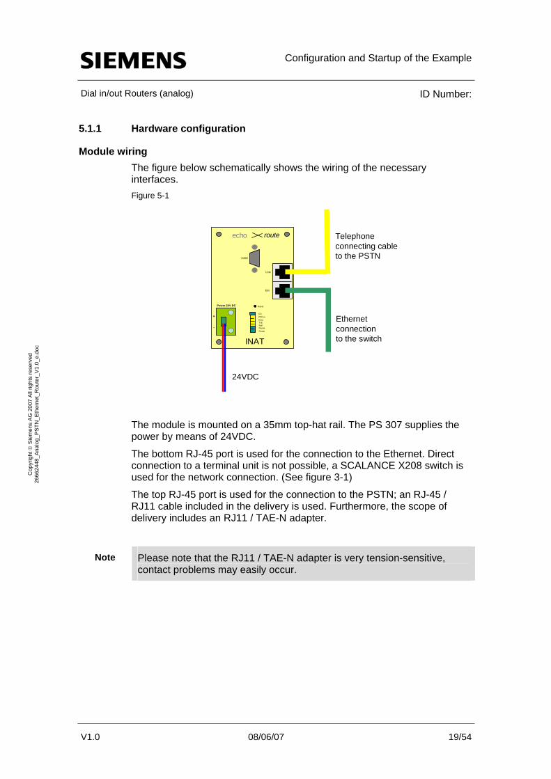
5.1.1 Hardware configuration
Module wiring The figure below schematically shows the wiring of the necessary interfaces. Figure 5-1
V1.0 08/06/07 19/54
Cop
yrig
ht ©
Sie
men
s A
G 2
007
All
right
s re
serv
ed
2666
2448
_Ana
log_
PST
N_E
ther
net_
Rou
ter_
V1.
0_e.
doc
echo route
Reset
CDPPPonDataTxERxE
PowerParam
Line
Eth
COM
INAT
Power 24V DC
+
-
24VDC
Ethernetconnection to the switch
Telephoneconnecting cable to the PSTN
The module is mounted on a 35mm top-hat rail. The PS 307 supplies the power by means of 24VDC.
The bottom RJ-45 port is used for the connection to the Ethernet. Direct connection to a terminal unit is not possible, a SCALANCE X208 switch is used for the network connection. (See figure 3-1)
The top RJ-45 port is used for the connection to the PSTN; an RJ-45 / RJ11 cable included in the delivery is used. Furthermore, the scope of delivery includes an RJ11 / TAE-N adapter.
Please note that the RJ11 / TAE-N adapter is very tension-sensitive, contact problems may easily occur.
Note

Configuration and Startup of the Example
Dial in/out Routers (analog) ID Number:
5.1.2 Basic module configuration
Configuring the IP address with the INATnet configuration tool The following section describes the basic configuration of the INAT router by the INATnet parameterization software.
This software requires direct access to the INAT router and has to be operated on a PC on the router network.
Starting the configuration software Double-click the “INATnet Parameterization” Figure 5-2
icon to start the parameterization tool.
V1.0 08/06/07 20/54
Cop
yrig
ht ©
Sie
men
s A
G 2
007
All
right
s re
serv
ed
2666
2448
_Ana
log_
PST
N_E
ther
net_
Rou
ter_
V1.
0_e.
doc
Figure 5-3

Configuration and Startup of the Example
Dial in/out Routers (analog) ID Number:
Selecting the station Select “Parameterization via Ip…” to open the “Select the Station via TCP/IP network” window. Figure 5-4
V1.0 08/06/07 21/54
Cop
yrig
ht ©
Sie
men
s A
G 2
007
All
right
s re
serv
ed
2666
2448
_Ana
log_
PST
N_E
ther
net_
Rou
ter_
V1.
0_e.
doc
All INAT modules automatically found in the connected network are displayed with their mac addresses.
If a router has already been parameterized, the station name, the device type and its IP address are additionally displayed here.

Configuration and Startup of the Example
Dial in/out Routers (analog) ID Number:
Assigning the IP address Select and right-click the module to open the Options menu. Figure 5-5
V1.0 08/06/07 22/54
Cop
yrig
ht ©
Sie
men
s A
G 2
007
All
right
s re
serv
ed
2666
2448
_Ana
log_
PST
N_E
ther
net_
Rou
ter_
V1.
0_e.
doc
In this menu, select “Change IP Address” and the following dialog box appears.

Configuration and Startup of the Example
Dial in/out Routers (analog) ID Number:
Figure 5-6
V1.0 08/06/07 23/54
Cop
yrig
ht ©
Sie
men
s A
G 2
007
All
right
s re
serv
ed
2666
2448
_Ana
log_
PST
N_E
ther
net_
Rou
ter_
V1.
0_e.
doc
Enter a station name selected by you, the IP address of the router and the subnet mask of the network in which the router is located.
Optionally, DHCP function and domain name server settings – not used in this application – can be made.
Use “OK” to assign the new IP parameters.
To obtain the updated data, the parameterization has to be restarted.

Configuration and Startup of the Example
Dial in/out Routers (analog) ID Number:
Figure 5-7
V1.0 08/06/07 24/54
Cop
yrig
ht ©
Sie
men
s A
G 2
007
All
right
s re
serv
ed
2666
2448
_Ana
log_
PST
N_E
ther
net_
Rou
ter_
V1.
0_e.
doc
After selecting the router, the router configuration can be continued by double-clicking or the “Edit” button.

Configuration and Startup of the Example
Dial in/out Routers (analog) ID Number:
5.1.3 Parameterizing the router functionality
Introduction The parameterization of the router functionality for the INAT configuration is divided into two sections:
• Modem connection
• Routing table entry
Both sections will be described in the following.
Parameterizing the modem connection After opening the Parameterization, this window is empty. Figure 5-8
V1.0 08/06/07 25/54
Cop
yrig
ht ©
Sie
men
s A
G 2
007
All
right
s re
serv
ed
2666
2448
_Ana
log_
PST
N_E
ther
net_
Rou
ter_
V1.
0_e.
doc
Select the Connection > New Router Entry menu options to create a new entry. “Connection with the Modem” has to be selected. Figure 5-9
Enter a name for the name of the connection, for example “Test Site”.
After selecting the “OK” button, the following parameterization window is displayed.

Configuration and Startup of the Example
Dial in/out Routers (analog) ID Number:
Figure 5-10
V1.0 08/06/07 26/54
Cop
yrig
ht ©
Sie
men
s A
G 2
007
All
right
s re
serv
ed
2666
2448
_Ana
log_
PST
N_E
ther
net_
Rou
ter_
V1.
0_e.
doc
The following parameters have to be observed:
Configuration and Startup of the Example
Dial in/out Routers (analog) ID Number:
V1.0 08/06/07 27/54
Cop
yrig
ht ©
Sie
men
s A
G 2
007
All
right
s re
serv
ed
2666
2448
_Ana
log_
PST
N_E
ther
net_
Rou
ter_
V1.
0_e.
doc
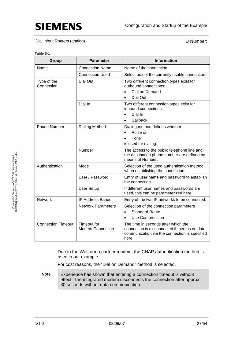
Table 5-1
Group Parameter Information
Connection Name Name of the connection Name Connection Used Select box of the currently usable connection. Dial Out Two different connection types exist for
outbound connections: • Dial on Demand • Dial Out
Type of the Connection
Dial In Two different connection types exist for inbound connections: • Dial In • Callback
Dialing Method Dialing method defines whether • Pulse or • Tone is used for dialing.
Phone Number
Number The access to the public telephone line and the destination phone number are defined by means of Number.
Mode Selection of the used authentication method when establishing the connection.
User / Password Entry of user name and password to establish the connection.
Authentication
User Setup If different user names and passwords are used, this can be parameterized here.
IP Address Bands Entry of the two IP networks to be connected. Network Network Parameters Selection of the connection parameters
• Standard Route • Use Compression
Connection Timeout Timeout for Modem Connection
The time in seconds after which the connection is disconnected if there is no data communication via the connection is specified here.
Due to the Westermo partner modem, the CHAP authentication method is used in our example.
For cost reasons, the “Dial on Demand” method is selected.
Note Experience has shown that entering a connection timeout is without effect. The integrated modem disconnects the connection after approx. 30 seconds without data communication.

Configuration and Startup of the Example
Dial in/out Routers (analog) ID Number:
Parameterizing the routing table entry After the configuration of the modem connection has been completed, click the “OK” button to display the following window: Figure 5-11
V1.0 08/06/07 28/54
Cop
yrig
ht ©
Sie
men
s A
G 2
007
All
right
s re
serv
ed
2666
2448
_Ana
log_
PST
N_E
ther
net_
Rou
ter_
V1.
0_e.
doc
Select the Connection > New Router Entry menu options to create an additional new entry. It is required that “Router Table Entry” is selected. Figure 5-12
Enter a name for the name of the router table entry, for example “Test_Connection”.
The router table entry name must differ from the modem connection name.
Note
Configuration and Startup of the Example
Dial in/out Routers (analog) ID Number:
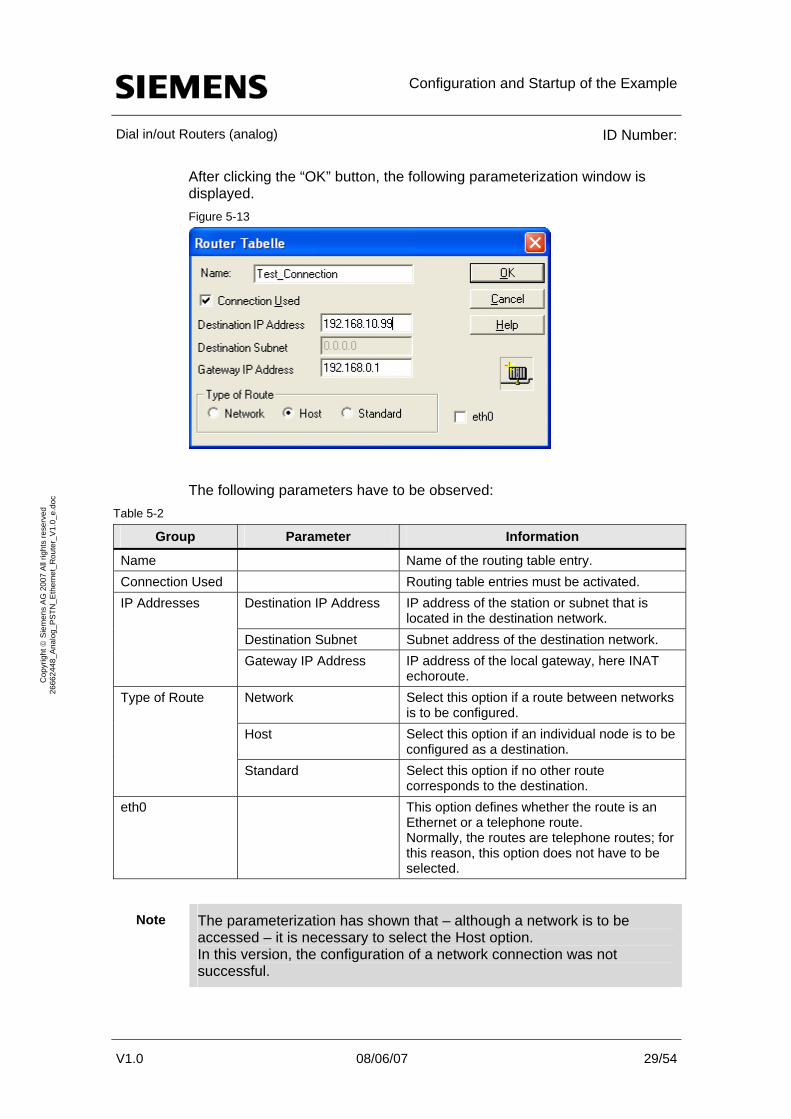
After clicking the “OK” button, the following parameterization window is displayed. Figure 5-13
V1.0 08/06/07 29/54
Cop
yrig
ht ©
Sie
men
s A
G 2
007
All
right
s re
serv
ed
2666
2448
_Ana
log_
PST
N_E
ther
net_
Rou
ter_
V1.
0_e.
doc
The following parameters have to be observed: Table 5-2
Parameter Information Group
Name Name of the routing table entry. Connection Used Routing table entries must be activated.
Destination IP Address IP address of the station or subnet that is located in the destination network.
Destination Subnet Subnet address of the destination network.
IP Addresses
Gateway IP Address IP address of the local gateway, here INAT echoroute.
Network Select this option if a route between networks is to be configured.
Host Select this option if an individual node is to be configured as a destination.
Type of Route
Standard Select this option if no other route corresponds to the destination. This option defines whether the route is an Ethernet or a telephone route. Normally, the routes are telephone routes; for this reason, this option does not have to be selected.
eth0
The parameterization has shown that – although a network is to be accessed – it is necessary to select the Host option. In this version, the configuration of a network connection was not successful.
Note

Configuration and Startup of the Example
Dial in/out Routers (analog) ID Number:
After completing the routing table configuration using the “OK” button, the following window is displayed: Figure 5-14
5.1.4 Setting modem dialing parameters
V1.0 08/06/07 30/54
Cop
yrig
ht ©
Sie
men
s A
G 2
007
All
right
s re
serv
ed
2666
2448
_Ana
log_
PST
N_E
ther
net_
Rou
ter_
V1.
0_e.
doc Changing the Router General Settings
To set the modem dialing parameters, select the Station > Router General Settings option via the menu. Subsequently, the following window opens. Figure 5-15
The following parameters have to be observed:
Configuration and Startup of the Example
Dial in/out Routers (analog) ID Number:
V1.0 08/06/07 31/54
Cop
yrig
ht ©
Sie
men
s A
G 2
007
All
right
s re
serv
ed
2666
2448
_Ana
log_
PST
N_E
ther
net_
Rou
ter_
V1.
0_e.
doc
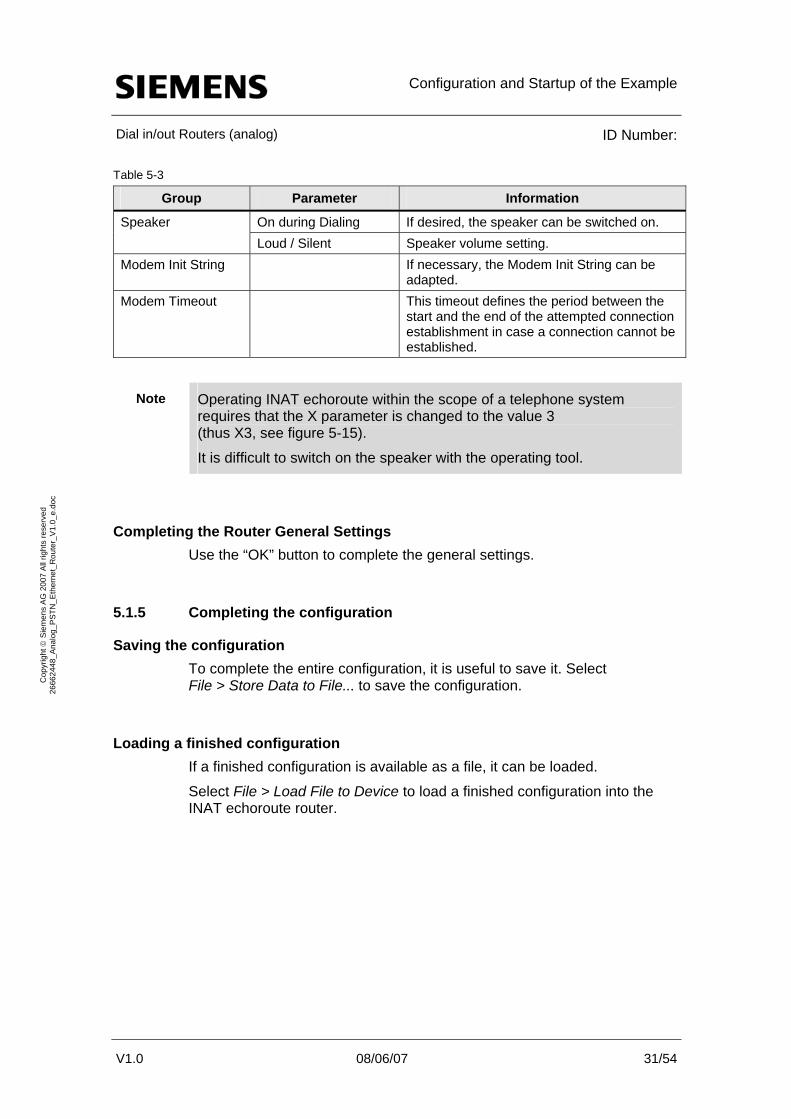
Table 5-3
Group Parameter Information
On during Dialing If desired, the speaker can be switched on. Speaker Loud / Silent Speaker volume setting.
Modem Init String If necessary, the Modem Init String can be adapted.
Modem Timeout This timeout defines the period between the start and the end of the attempted connection establishment in case a connection cannot be established.
Note Operating INAT echoroute within the scope of a telephone system requires that the X parameter is changed to the value 3 (thus X3, see figure 5-15).
It is difficult to switch on the speaker with the operating tool.
Completing the Router General Settings Use the “OK” button to complete the general settings.
5.1.5 Completing the configuration
Saving the configuration To complete the entire configuration, it is useful to save it. Select File > Store Data to File... to save the configuration.
Loading a finished configuration If a finished configuration is available as a file, it can be loaded.
Select File > Load File to Device to load a finished configuration into the INAT echoroute router.

Configuration and Startup of the Example
Dial in/out Routers (analog) ID Number:
V1.0 08/06/07 32/54
Cop
yrig
ht ©
Sie
men
s A
G 2
007
All
right
s re
serv
ed
2666
2448
_Ana
log_
PST
N_E
ther
net_
Rou
ter_
V1.
0_e.
doc
5.2 Westermo ZR-200 router configuration
Constraints Firmware version ZR-200_V09 was used in this version of the ZR-200 router. The restriction of this ZR-200 version is that it is a mere dial in router. It is thus not possible to call or call back another participant.
According to Westermo Support, the dial out function will be implemented with the next firmware release.
Introduction The Westermo ZR-200 router is a compact router that is available in three versions:
• Analog modem,
• ISDN modem,
• serial interfaces.
The router parameterization is web-based and performed using an internet browser.
Further software for the parameterization is not required.

Configuration and Startup of the Example
Dial in/out Routers (analog) ID Number:
5.2.1 Hardware configuration
Module wiring The figure below schematically shows the wiring of the necessary interfaces. Figure 5-16
V1.0 08/06/07 33/54
Cop
yrig
ht ©
Sie
men
s A
G 2
007
All
right
s re
serv
ed
2666
2448
_Ana
log_
PST
N_E
ther
net_
Rou
ter_
V1.
0_e.
doc
ZR-200
LINE
ETH
TDi
PWR DCD
RDi
BSYETH
TDe RDe
DEF CON
Ethernetconnection to the switch
Telephoneconnecting cableto the PSTN
24VDC
The module is mounted on a 35mm top-hat rail. The power is supplied by means of 24VDC from the PS 307.
The top RJ-45 port is used for the connection to the Ethernet. Direct connection to a terminal unit is not possible, the SCALANCE X208 switch is used for the network connection. (See figure 3-1)
The bottom RJ-45 port is used for the connection to the PSTN; a special cable with TAE-N connector is included in the delivery of the router.
Configuration and Startup of the Example
Dial in/out Routers (analog) ID Number:
V1.0 08/06/07 34/54
Cop
yrig
ht ©
Sie
men
s A
G 2
007
All
right
s re
serv
ed
2666
2448
_Ana
log_
PST
N_E
ther
net_
Rou
ter_
V1.
0_e.
doc
5.2.2 Basic module configuration
Configuring the IP address By default, the IP address of the router is set to 192.168.0.5.
If a change of this address is required, this change has to be made when parameterizing.
Resetting the IP address If the IP address has been changed and if this information has been lost, the IP address can be reset to the default setting. This is possible by setting the DIP switches.
Set DIP switch 2 to “on”.
The device is then set to configuration mode and the IP address is reset to the default setting (IP 192.168.0.5).

Configuration and Startup of the Example
Dial in/out Routers (analog) ID Number:
5.2.3 Opening the parameterization menu
Introduction The router can be conveniently parameterized using a web browser. The following sections describe in particular the functions that are necessary for this application.
For a detailed description of the router, please refer to the technical documentation included in the delivery.
Please observe that the IP address of your PG is in the 192.168.0.X address band and that it has to be changed later.
Note
Opening the router HTML page
V1.0 08/06/07 35/54
Cop
yrig
ht ©
Sie
men
s A
G 2
007
All
right
s re
serv
ed
2666
2448
_Ana
log_
PST
N_E
ther
net_
Rou
ter_
V1.
0_e.
doc
After opening your web browser, enter the default address of the router in the address bar and press Return to confirm.
The following page opens: Figure 5-17

Configuration and Startup of the Example
Dial in/out Routers (analog) ID Number:
Select the desired language and click the corresponding flag with the mouse.
Main menu After selecting the language, the main menu opens: Figure 5-18
V1.0 08/06/07 36/54
Cop
yrig
ht ©
Sie
men
s A
G 2
007
All
right
s re
serv
ed
2666
2448
_Ana
log_
PST
N_E
ther
net_
Rou
ter_
V1.
0_e.
doc
The selection of the following menu options is displayed: Table 5-4
Menu option Description
Startside Link to this page, the main menu. Network / Routing Settings for the PPP modem connection. PPP Configuration Settings for the router in standby mode and further PPP settings.
Configuration Overview Overview of the configured router configuration. Configuration File Saving and reading a present configuration file.
Reboot Reboots the ZR-200 router.

Configuration and Startup of the Example
Dial in/out Routers (analog) ID Number:
5.2.4 Parameterizing the router functionality
Introduction This version of the router does not support the complete functional scope of a dial in/out router; for this reason, the two following menus have to be observed when configuring the dial in functionality.
• Network / Routing
• PPP Configuration
Both menus will be considered in the following sections.
PPP is an abbreviation for Point-to-Point Protocol. This is a protocol for connection establishment via dial-up connections.
Note
V1.0 08/06/07 37/54
Cop
yrig
ht ©
Sie
men
s A
G 2
007
All
right
s re
serv
ed
2666
2448
_Ana
log_
PST
N_E
ther
net_
Rou
ter_
V1.
0_e.
doc Network / Routing menu
After selecting the “Network / Routing” menu option, the following parameters are displayed: Figure 5-19
The used parameters have the following meaning:

Configuration and Startup of the Example
Dial in/out Routers (analog) ID Number:
V1.0 08/06/07 38/54
Cop
yrig
ht ©
Sie
men
s A
G 2
007
All
right
s re
serv
ed
2666
2448
_Ana
log_
PST
N_E
ther
net_
Rou
ter_
V1.
0_e.
doc
Table 5-5
Parameter Information
Remote PPP-IP IP address of the calling party. This address is suggested to a calling device. In this example, the INAT router also uses this address. For the workstation PC, this address is assigned to the PC.
Local PPP-IP The IP address of the ZR-200 router with which the connection to the remote network is established. This address is also specified as a default router in the parameterizations of the nodes.
Local IP Address The IP address of the ZR-200 router in the local network must differ from the local PPP-IP address.
Local Subnet-Mask Subnet mask of the router in the local network. Username The user name used for the authentication. Password The password used for the authentication.
Note When establishing the connection, the Westermo ZR-200 router supports only CHAP authentication; other authentication methods cannot be selected.
Use the “Send Parameter” button to complete the Network / Routing parameterization.
Configuration and Startup of the Example
Dial in/out Routers (analog) ID Number:
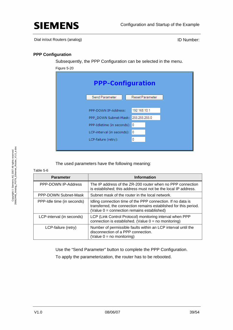
PPP Configuration Subsequently, the PPP Configuration can be selected in the menu. Figure 5-20
V1.0 08/06/07 39/54
Cop
yrig
ht ©
Sie
men
s A
G 2
007
All
right
s re
serv
ed
2666
2448
_Ana
log_
PST
N_E
ther
net_
Rou
ter_
V1.
0_e.
doc
The used parameters have the following meaning: Table 5-6
Parameter Information
PPP-DOWN IP-Address The IP address of the ZR-200 router when no PPP connection is established; this address must not be the local IP address.
PPP-DOWN Subnet-Mask Subnet mask of the router in the local network. PPP-Idle time (in seconds) Idling connection time of the PPP connection. If no data is
transferred, the connection remains established for this period. (Value 0 = connection remains established)
LCP-interval (in seconds) LCP (Link Control Protocol) monitoring interval when PPP connection is established. (Value 0 = no monitoring) Number of permissible faults within an LCP interval until the disconnection of a PPP connection. (Value 0 = no monitoring)
LCP-failure (retry)
Use the “Send Parameter” button to complete the PPP Configuration.
To apply the parameterization, the router has to be rebooted.
Configuration and Startup of the Example
Dial in/out Routers (analog) ID Number:
5.3 Network settings on the PC
Windows network settings In the IP parameterization settings, the local dialing router has to be set up as a default gateway. This is necessary since the router establishes the connection to other networks and thus has to be considered by the Windows IP stack (Winsock).
This requires a fixed IP addressing of the PC.
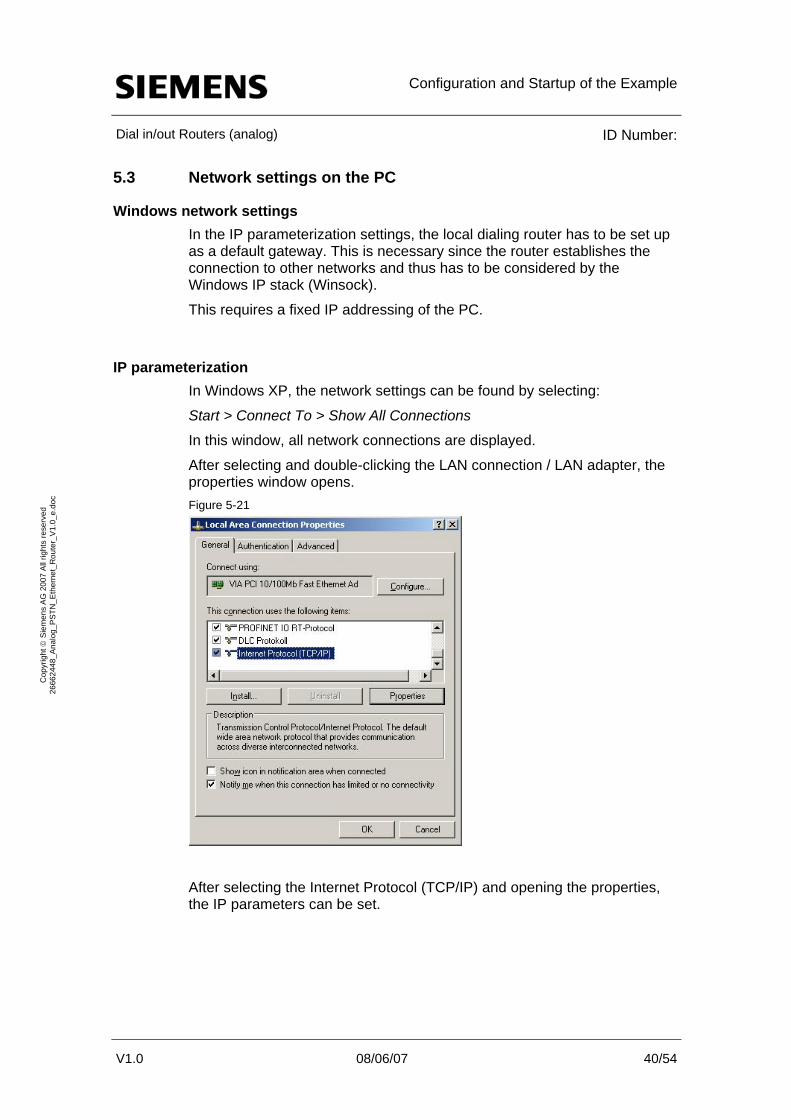
IP parameterization In Windows XP, the network settings can be found by selecting:
Start > Connect To > Show All Connections
In this window, all network connections are displayed.
After selecting and double-clicking the LAN connection / LAN adapter, the properties window opens.
V1.0 08/06/07 40/54
Cop
yrig
ht ©
Sie
men
s A
G 2
007
All
right
s re
serv
ed
2666
2448
_Ana
log_
PST
N_E
ther
net_
Rou
ter_
V1.
0_e.
doc
Figure 5-21
After selecting the Internet Protocol (TCP/IP) and opening the properties, the IP parameters can be set.

Configuration and Startup of the Example
Dial in/out Routers (analog) ID Number:
Figure 5-22
V1.0 08/06/07 41/54
Cop
yrig
ht ©
Sie
men
s A
G 2
007
All
right
s re
serv
ed
2666
2448
_Ana
log_
PST
N_E
ther
net_
Rou
ter_
V1.
0_e.
doc
The required parameters are listed in the following table: Table 5-7
Parameter Information
IP address The IP address of the computer in the IP network. It has to be located in the subnet of the local router (INAT echoroute).
Subnet mask The subnet mask of the local network. Default gateway The IP address of the router to be used, here INAT
echoroute. The IP address of the DNS server if systems with domain names are used. (Mainly used on the internet / intranet)
DNS server
These settings are network-dependent and, in this example, explicitly considered for the application in network A.
All further functions are processed by the Windows IP stack (Winsock). All applications based on TCP/IP, including STEP 7, work with these settings; it is thus not necessary to make further settings in the applications.
Configuration and Startup of the Example
Dial in/out Routers (analog) ID Number:
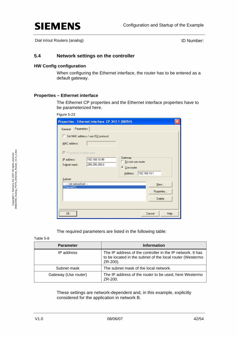
5.4 Network settings on the controller
HW Config configuration When configuring the Ethernet interface, the router has to be entered as a default gateway.
Properties – Ethernet interface The Ethernet CP properties and the Ethernet interface properties have to be parameterized here. Figure 5-23
V1.0 08/06/07 42/54
Cop
yrig
ht ©
Sie
men
s A
G 2
007
All
right
s re
serv
ed
2666
2448
_Ana
log_
PST
N_E
ther
net_
Rou
ter_
V1.
0_e.
doc
The required parameters are listed in the following table: Table 5-8
Parameter Information
IP address The IP address of the controller in the IP network. It has to be located in the subnet of the local router (Westermo ZR-200).
Subnet mask The subnet mask of the local network. The IP address of the router to be used, here Westermo ZR-200.
Gateway (Use router)
These settings are network-dependent and, in this example, explicitly considered for the application in network B.

Configuration and Startup of the Example
Dial in/out Routers (analog) ID Number:
5.5 Using dial-up connections from the workstation PC
Introduction As already mentioned in chapter 1, a modem / router connection can be used as an alternative to the router / router connection.
The necessary parameterization steps for the workstation PC in Windows XP are explained in the following chapter.
The ZR-200 dial in/out router manufactured by Westermo is used as a partner station.
5.5.1 Creating a dial-up connection
Network settings in Windows XP To set up a dial-up connection, the Microsoft New Connection Wizard has to be used. Start it by selecting
V1.0 08/06/07 43/54
Cop
yrig
ht ©
Sie
men
s A
G 2
007
All
right
s re
serv
ed
2666
2448
_Ana
log_
PST
N_E
ther
net_
Rou
ter_
V1.
0_e.
doc Start > Settings > Control Panel > Network Connections >
New Connection Wizard
Welcome The wizard starts with this window: Figure 5-24
Click the “Next” button.
Configuration and Startup of the Example
Dial in/out Routers (analog) ID Number:
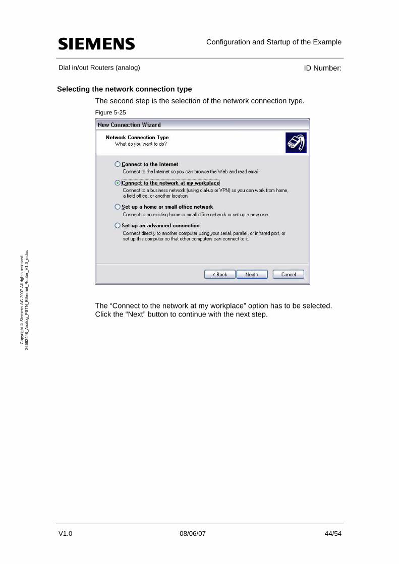
Selecting the network connection type The second step is the selection of the network connection type. Figure 5-25
V1.0 08/06/07 44/54
Cop
yrig
ht ©
Sie
men
s A
G 2
007
All
right
s re
serv
ed
2666
2448
_Ana
log_
PST
N_E
ther
net_
Rou
ter_
V1.
0_e.
doc
The “Connect to the network at my workplace” option has to be selected. Click the “Next” button to continue with the next step.
Configuration and Startup of the Example
Dial in/out Routers (analog) ID Number:
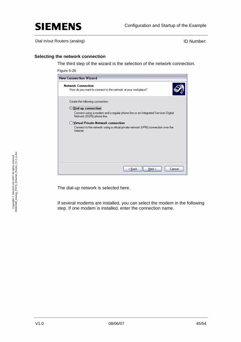
Selecting the network connection The third step of the wizard is the selection of the network connection. Figure 5-26
V1.0 08/06/07 45/54
Cop
yrig
ht ©
Sie
men
s A
G 2
007
All
right
s re
serv
ed
2666
2448
_Ana
log_
PST
N_E
ther
net_
Rou
ter_
V1.
0_e.
doc
The dial-up network is selected here.
If several modems are installed, you can select the modem in the following step. If one modem is installed, enter the connection name.
Configuration and Startup of the Example
Dial in/out Routers (analog) ID Number:
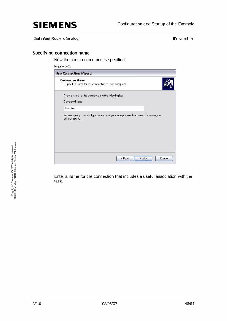
Specifying connection name Now the connection name is specified. Figure 5-27
V1.0 08/06/07 46/54
Cop
yrig
ht ©
Sie
men
s A
G 2
007
All
right
s re
serv
ed
2666
2448
_Ana
log_
PST
N_E
ther
net_
Rou
ter_
V1.
0_e.
doc
Enter a name for the connection that includes a useful association with the task.

Configuration and Startup of the Example
Dial in/out Routers (analog) ID Number:
Entering phone number to dial The last but one step of the wizard is the entry of the phone number at which the partner can be reached. Figure 5-28
V1.0 08/06/07 47/54
Cop
yrig
ht ©
Sie
men
s A
G 2
007
All
right
s re
serv
ed
2666
2448
_Ana
log_
PST
N_E
ther
net_
Rou
ter_
V1.
0_e.
doc
The phone number entered here must meet the requirements of the telephone connection or telephone system.
Please observe that the modem settings of your workstation PC may differ depending on the used telephone connection.
Note

Configuration and Startup of the Example
Dial in/out Routers (analog) ID Number:
Completing the wizard The wizard completes with the following window. Figure 5-29
V1.0 08/06/07 48/54
Cop
yrig
ht ©
Sie
men
s A
G 2
007
All
right
s re
serv
ed
2666
2448
_Ana
log_
PST
N_E
ther
net_
Rou
ter_
V1.
0_e.
doc
The dial-up connection has now been created. By selecting the “Add a shortcut to this connection to my desktop” option, the dial-up connection can also be opened directly from the desktop.

Configuration and Startup of the Example
Dial in/out Routers (analog) ID Number:
5.5.2 Adjusting the dial-up connection settings
Changing parameters The default settings of the dial-up connection are not sufficient for use with the Westermo ZR-200 router. Several additional settings have to be made that are described in the following sections.
When you are using a different router than ZR-200, additional parameters may deviate and have to be adjusted. Please check this using the manufacturer documentation.
Entering login parameters Open the dial-up connection via the just created shortcut or by selecting
Start > Settings > Network Connections. Figure 5-30
V1.0 08/06/07 49/54
Cop
yrig
ht ©
Sie
men
s A
G 2
007
All
right
s re
serv
ed
2666
2448
_Ana
log_
PST
N_E
ther
net_
Rou
ter_
V1.
0_e.
doc
In User name and Password, enter the data that were configured in the ZR-200 router. If desired, the “Save this user name and password for the following users:” option can be selected to store the user information in the computer.
Use the “Properties” button to display the advanced settings.

Configuration and Startup of the Example
Dial in/out Routers (analog) ID Number:
Changing LCP settings The only parameter that does not fit in the default parameters of the dial-up connection is the LCP extension setting.
It is required to adapt this parameter since the Westermo ZR-200 router has parameterized this parameter accordingly.
In the properties of the connection, select the Networking tab. Figure 5-31
V1.0 08/06/07 50/54
Cop
yrig
ht ©
Sie
men
s A
G 2
007
All
right
s re
serv
ed
2666
2448
_Ana
log_
PST
N_E
ther
net_
Rou
ter_
V1.
0_e.
doc
Now select the “Settings” of the dial-up server. Figure 5-32
Deactivate the “Enable LPC extensions” option. Confirm this and the next window with “OK”.
Select Dial to establish the connection to the Westermo ZR-200 router.

Configuration and Startup of the Example
Dial in/out Routers (analog) ID Number:
V1.0 08/06/07 51/54
Cop
yrig
ht ©
Sie
men
s A
G 2
007
All
right
s re
serv
ed
2666
2448
_Ana
log_
PST
N_E
ther
net_
Rou
ter_
V1.
0_e.
doc
5.5.3 Setting the online interface for STEP 7
NdisWanIp To apply the dial-up connection in STEP 7, it is absolutely necessary that the used NdisWanIp interface parameter assignment is used.
For users of ISDN cards or ISDN adapters, this can also be selected in “Set PG/PC Interface…”; however, this is not possible when using analog modems. The interface is actively disabled by STEP 7.
Activating the interface To operate the interface despite this restriction, a change in the registry is required. The key necessary for this change is located here:
HKEY_LOCAL_MACHINE\SOFTWARE\Siemens\SINEC\LogDevices\TCP/IP -> NdisWanIp\NDi
The “Hidden” key has to be set to “no”.
The entry in the PG/PC interface can now be selected and used.
Note STEP 7 checks and resets this setting at regular intervals. Consequently, the entry has to be changed frequently.
ATTENTION Changing registry entries is at your own risk!
Performance Data
Dial in/out Routers (analog) ID Number:
V1.0 08/06/07 52/54
Cop
yrig
ht ©
Sie
men
s A
G 2
007
All
right
s re
serv
ed
2666
2448
_Ana
log_
PST
N_E
ther
net_
Rou
ter_
V1.
0_e.
doc
6 Performance Data
6.1 Constraints
Technical restrictions From a technical perspective three decisive restrictions have to be named that are briefly described below.
• The applicable data bandwidth; the data bandwidth ensues from the used communication connection. An analog telephone connection is used, the maximum bandwidth is 48kb upstream and 56kb downstream.
• The response time; the response time is the period the communication requires to reach the partner and to be answered. In a local network, this period is very short, mostly < 1ms. On the internet, this response time can quickly increase to > 100ms. The response times of analog telephone connections are comparable to those on the internet. Fast online functions (in the real-time range) as are necessary with SIMOTION are thus not possible.
• The connection establishment; when using analog modems, the connection establishment is very time-consuming. Waiting times of 30 seconds may easily occur; this has to be observed for online functions. If necessary, the connection has to be established before the online function using the Ping IP function.
6.2 Experiences from the application
PG functions via the remote access
• read out diagnostic data,
• program downloads and
• monitor variables / blocks
are possible.
The use of this solution with STEP7 and SIMOTION SCOUT is recommended under the described circumstances. No further restrictions were observed.
An IP-based use of WinCC flexible (for the configuration), FTP, http is also possible. We advise against using Runtime functions with WinCC flexible since the response times via the dial-up connection are inadequate.

Performance Data
Dial in/out Routers (analog) ID Number:
V1.0 08/06/07 53/54
Cop
yrig
ht ©
Sie
men
s A
G 2
007
All
right
s re
serv
ed
2666
2448
_Ana
log_
PST
N_E
ther
net_
Rou
ter_
V1.
0_e.
doc
Note Use in the settings of the PG/PC panel of your PC the configuration of the fixed IP address.
The function TCP/IP (Auto) -> [NIC] does not work as soon as different IP subnets are being used. This is because this feature tries to set up an IP address of the destination IP subnet on the PC. With the revised IP address the PC loses the assignment to the local router and the connection can not be established.

History
Dial in/out Routers (analog) ID Number:
V1.0 08/06/07 54/54
Cop
yrig
ht ©
Sie
men
s A
G 2
007
All
right
s re
serv
ed
2666
2448
_Ana
log_
PST
N_E
ther
net_
Rou
ter_
V1.
0_e.
doc
7 History Table 7-1
Version Date Modification
V1.0 08/06/07 First edition