Embed Size (px)
Citation preview

802-HDBK-0002SUBORBITAL AND SPECIAL ORBITAL PROJECTS DIRECTORATE
Wallops Flight Facility Geophysical Observatory
Handbook
Original Effective June 1, 2007
Expiration June 1, 2012
Signature on file
Bruce E. Underwood, Chief Advanced Projects Office
Goddard Space Flight Center
Wallops Flight Facility Wallops Island, Virginia 23337
National Aeronautics and Space Administration
Check the Wallops Documentation Web site at http://www.nasa.gov/centers/wallops/multimedia/index.html to verify this is the correct version prior to use.

802-HDBK-0002 2 of 31
Change History
Revision Effective Date
Description of Changes
Original June 1, 2007 Initial Release
Check the Wallops Documentation Web site at http://www.nasa.gov/centers/wallops/multimedia/index.html to verify this is the correct version prior to use.

802-HDBK-0002 3 of 31
Preface
The NASA/Goddard Space Flight Center (GSFC) operates the Wallops Flight Facility (WFF) located on the Eastern Shore of Virginia. NASA supports space and Earth science research and aerospace technology development through the use of rockets, balloons, aircraft, and uninhabited aerial vehicles (UAVs). In support of these activities, Wallops offers a variety of services and operates a number of unique research facilities, including a launch range, research airport, separate UAV runway on Wallops Island, scientific laboratories, and manufacturing and testing facilities. Because of unique scientific requirements, Wallops also maintains capabilities to conduct research activities worldwide. Wallops’ customers represent NASA, other United States Government agencies, foreign and commercial organizations, and educational institutions.
The Wallops Flight Facility Geophysical Observatory (WGO) User’s Handbook provides descriptions of WGO facilities and capabilities. The handbook also describes the various support functions and facilities available to the customer. Additional copies of the WGO User’s Handbook may be obtained from the Advanced Projects Office, NASA, GSFC/Wallops Flight Facility, Wallops Island, VA 23337-5099; or it may be downloaded from the WFF Web site at http://www.nasa.gov/centers/wallops/multimedia/index.html.
RUH940713
WASHINGTON, DC
BALTIMORE
MARYLAND NEW JERSEY
DELAWARE
VIRGINIA
SALISBURY
NASA/GSFC WALLOPS
FLIGHT FACILITY
NORFOLK
Neither the United States Government nor any person acting on behalf of the United States Government assumes any liability resulting from the use of information contained in this document, or warrants that such use shall be free from privately owned rights. Use of a company product name does not imply approval or recommendation of the product to the exclusion of others that may also be suitable.
Check the Wallops Documentation Web site at http://www.nasa.gov/centers/wallops/multimedia/index.html to verify this is the correct version prior to use.

802-HDBK-0002 4 of 31
This page intentionally left blank.
Check the Wallops Documentation Web site at http://www.nasa.gov/centers/wallops/multimedia/index.html to verify this is the correct version prior to use.

802-HDBK-0002 5 of 31
Abbreviations, Acronyms, and Initializations
AFOH Airport Facility and Operations Handbook APCR Aeronautical Projects Control Room ASRF Atmospheric Sciences Research Facility ATM Automatic Teller Machine AWIPS Advanced Weather Interactive Processing System CAD Computer-aided Design CAM Computer-aided Manufacture CD-ROM Compact Disk - Read Only Memory CFR Crash Fire and Rescue CNC Computer Numerically Controlled COTS Commercial Off-the-Shelf DC District of Columbia EDARS Environmental Data Acquisition and Recording System ELF Extremely Low Frequency ELV Expendable Launch Vehicle EMI Electromagnetic Interference EMS Emergency Medical Services EOC Emergency Operations Center FAA Federal Aviation Administration FTS Federal Telecommunication System GNC Guidance, Navigation and Control GPG Goddard Procedures and Guidelines GPS Global Positioning System GSFC Goddard Space Flight Center HB Handbook HDBK Handbook HF High Frequency IMU Inertial Measurement Unit JP Jet Petroleum JPTS Jet Propellant Thermally Stable LDARS Lightning Detection and Ranging System LDS Lightening Detection System LEADS Leading and Environmental Display System MAC Morale Activities Committee MF Mid-Frequency MSDS Material Safety Data Sheet NACA National Advisory Committee for Aeronautics NASA National Aeronautics and Space Administration NASAFCU NASA Federal Credit Union NEPA National Environmental Policy Act NIST National Institute of Standards and Testing NLDN National Lightning Detection Network NWS National Weather Service ODIN Outsourcing Desktop Initiative for NASA PAO Public Affairs Office PBX Private Branch Exchange RF Radio Frequency RFI Radio Frequency Interference SPANDAR S-band Space and Range Radar SRP Sounding Rocket Program SSOPD Suborbital and Special Orbital Projects Directorate SuperDARN Super Dual Auroral Radar Network TM Telemetry
Check the Wallops Documentation Web site at http://www.nasa.gov/centers/wallops/multimedia/index.html to verify this is the correct version prior to use.

802-HDBK-0002 6 of 31
TV Television U.S. United States UAV Uninhabited Aerial Vehicle UHF Ultra-high Frequency UNICOM Uniform Communication USA United States of America VA Virginia VFR Visual Flight Rules WEMA Wallops Employee and Morale Association WFF Wallops Flight Facility WGO Wallops Geophysical Observatory WSSEB Wallops Systems Software Engineering Branch
Check the Wallops Documentation Web site at http://www.nasa.gov/centers/wallops/multimedia/index.html to verify this is the correct version prior to use.

802-HDBK-0002 7 of 31
Table of Contents
Page Change History ........................................................................................................................................2 Preface ..........................................................................................................................................3 Abbreviations, Acronyms, and Initializations............................................................................................5 Section I: Introduction ..............................................................................................................................9
1.1 Introduction ..............................................................................................................................9 1.2 Geography ...............................................................................................................................9 1.3 Wallops Research Range ........................................................................................................9 1.4 Operational History ..................................................................................................................9
Section II: Wallops Geophysical Observatory........................................................................................11 2.1 Introduction ............................................................................................................................11 2.2 WGO Structure ......................................................................................................................11 2.3 WGO Components.................................................................................................................12
Section III: Facilities and Capabilities ....................................................................................................18 3.1 Wallops Flight Facilty Runways .............................................................................................18 3.2 Hangars .................................................................................................................................19 3.3 Fuel Farm...............................................................................................................................20 3.4 Control Tower ........................................................................................................................20 3.5 Range Control Centers ..........................................................................................................20 3.6 Telemetry Facilities................................................................................................................20 3.7 Radar Facilities ......................................................................................................................21 3.8 Frequency Utilization and Management ................................................................................21 3.9 Weather Forecast Office........................................................................................................21 3.10 Engineering............................................................................................................................22 3.11 Fabrication Facilities ..............................................................................................................22 3.12 Environmental Test Facilities.................................................................................................23 3.13 Sciene Facilities .....................................................................................................................23 3.14 GPS Simulator Facility...........................................................................................................24
Section IV: Institutional Services............................................................................................................25 4.1 Crash Fire and Rescue..........................................................................................................25 4.2 Security ..................................................................................................................................25 4.3 Metrology Laboaratory...........................................................................................................25 4.4 Chemical Laboratory..............................................................................................................25 4.5 Environmental ........................................................................................................................25 4.6 Shipping/Receiving ................................................................................................................26 4.7 Motor Freight Truck Service ..................................................................................................26 4.8 Air Cargo................................................................................................................................26 4.9 Customs.................................................................................................................................27 4.10 Post Office .............................................................................................................................27 4.11 Material Handling Equipment.................................................................................................27 4.12 Warehousing and Hazardous Materials Storage...................................................................27 4.13 Fire Protection........................................................................................................................27 4.14 Medical Facilities....................................................................................................................27 4.15 Communications ....................................................................................................................27
Check the Wallops Documentation Web site at http://www.nasa.gov/centers/wallops/multimedia/index.html to verify this is the correct version prior to use.

802-HDBK-0002 8 of 31
4.16 Library ..................................................................................................................................28 4.17 Print Shop ..............................................................................................................................28 4.18 Photo Services.......................................................................................................................28 4.19 NASA Federal Credit Union...................................................................................................28 4.20 Cafeteria and Dormitories......................................................................................................28 4.21 Fitness Facility .......................................................................................................................29 4.22 Public Affairs Support ............................................................................................................29
Appendix: References............................................................................................................................31
List of Figures
Figure 1. Wallops Flight Facility ..............................................................................................................9 Figure 2. Current WGO Layout and Connectivity .................................................................................11 Figure 3. ASRF and SPANDAR............................................................................................................12 Figure 4. Magnetometer and Pedestal..................................................................................................13 Figure 5. SuperDARN Array..................................................................................................................14 Figure 6. Dynasonde 21 Array on Wallops Main Base .........................................................................16 Figure 7. WGO Shelter Relative to the Magnetometer Pedestal ..........................................................17 Figure 8. UAV Runway on Wallops Island............................................................................................18 Figure 9. WFF Research Airport with Associated Facilities..................................................................19 Figure 10. Wallops Flight Facility Hangars ...........................................................................................20 Figure 11. View of Machine Shop Floor................................................................................................23
Check the Wallops Documentation Web site at http://www.nasa.gov/centers/wallops/multimedia/index.html to verify this is the correct version prior to use.

802-HDBK-0002 9 of 31
Section I: Introduction 1.1 Introduction
The National Aeronautics and Space Act of 1958 (Space Act), as amended, charters NASA to plan, direct, and conduct space activities. The Space Act authorizes NASA field installations to establish policies and operational interface procedures for users of NASA resources. Activities under the Space Act are to be conducted to optimize America’s scientific and engineering resources. NASA is authorized to enter into contracts, leases, cooperative agreements, and other transactions on such terms as it may deem appropriate with any person, firm, association, or corporation. NASA is also authorized to cooperate with public and private agencies in the use of Government-provided launch support, services, equipment, and facilities.
1.2 Geography The Wallops Main Base is located on Virginia’s Eastern Shore 5 miles west of
Chincoteague, Virginia, approximately 90 miles north of Norfolk, Virginia, and 40 miles southeast of Salisbury, Maryland. The Facility consists of three separate parcels of real property: the Main Base, the Mainland, and the Wallops Island Launch Site. The Mainland and Island are approximately 7 miles southeast of the Main Base. Figure 1 shows WFF and the relationship of the three properties.
1.3 Wallops Research Range The Wallops Research Range is part of Wallops
Flight Facility and is managed by GSFC Suborbital and Special Orbital Projects Directorate (SSOPD). The range consists of a launch range, an aeronautical research airport, a UAV runway on Wallops Island, and associated tracking, data acquisition, and control instrumentation systems. The range includes authorized operating space, primarily over the Atlantic Ocean, and authorized frequency spectrum. Scientists and engineers from NASA, other United States Government agencies, colleges and universities, commercial organizations, and the worldwide scientific community have conducted experiments at the range. Figure 1. Wallo ght Faci
ps Fli lity
1.4 Operational History or agency, the National Advisory Committee for Aeronautics
(NACA
ess established the National Aeronautics and Space Administration (NASA
In 1945, NASA's predecess), established a launch site on Wallops Island under the direction of the Langley
Research Center. This site was designated the Pilotless Aircraft Research Station and conducted high-speed aerodynamic research to supplement wind tunnel and laboratory investigations into the problems of flight.
In 1958, Congr), which absorbed Langley Research Center and other NACA field centers and research
Check the Wallops Documentation Web site at http://www.nasa.gov/centers/wallops/multimedia/index.html to verify this is the correct version prior to use.

802-HDBK-0002 10 of 31
facilities. At that time, the Pilotless Aircraft Research Station became a separate facility - Wallops Station - operating directly under NASA Headquarters in Washington, DC.
In 1959, NASA acquired the former Chincoteague Naval Air Station, and engineering and administrative activities were moved to this location. In 1974, the Wallops Station was renamed Wallops Flight Center. The name was changed to Wallops Flight Facility in 1981, when it became part of Goddard Space Flight Center, Greenbelt, Maryland.
Since 1945, the Wallops Research Range has launched thousands of research vehicles in the quest for information on the flight characteristics of airplanes, launch vehicles, and spacecraft, and to increase the knowledge of the Earth's upper atmosphere and the near space environment. The launch vehicles vary in size and power from the small Super Loki meteorological rockets to orbital class vehicles.
Wallops Flight Facility continues to be a small, fast response, matrix organization that can accomplish rocket and balloon projects, spacecraft orbital tracking, airborne science support, and aeronautical research.
For information on doing business with Wallops, see 802-HDBK-0001, Doing Business at Wallops Flight Facility: A Customer Guide, which can be found at http://www.nasa.gov/centers/wallops/multimedia/index.html.
Check the Wallops Documentation Web site at http://www.nasa.gov/centers/wallops/multimedia/index.html to verify this is the correct version prior to use.

802-HDBK-0002 11 of 31
Section II: Wallops Geophysical Observatory 2.1 Introduction
The Wallops Geophysical Observatory (WGO) allows customers to conduct measurements from ground-based scientific research instrumentation. WGO resources can be utilized for stand-alone science or in conjunction with flight projects. The WGO is intended to augment and enhance flight-vehicle-based test equipment during scientific missions, especially those conducted as part of the Coastal Zone Research program. It will also provide a platform for collecting and observing data worldwide for students and others in the community of interest. The WGO includes a fully integrated network of devices accessible locally in the WGO shelter, at the WFF Range Control Center, and through connectivity to the NASA Intranet and World Wide Web.
2.2 WGO Structure The WGO was conceived in 2001 and began modestly as an idea with very little funding.
Over time, the system obtained some key equipment, a shelter for the system, and connectivity. The system is still evolving but has now reached a critical mass of capability useful for scientific applications. Figure 2 depicts the current layout and connectivity of the WGO.
Magnetometer Pedestal
GPS Scintillation Receiver
WGO HF Radar and TrailerAntenna Array
SPANDAR
U40
U30
Other Systems WFF/WGO - Dynasonde Public User
Network - Lightning Detection
Figure 2. Current WGO Layout and Connectivity
WWW- Field Mills - Etc.
Check the Wallops Documentation Web site at http://www.nasa.gov/centers/wallops/multimedia/index.html to verify this is the correct version prior to use.

802-HDBK-0002 12 of 31
2.3 WGO Components
2.3.1 Atmospheric Sciences Research Facility (ASRF) The Atmospheric Sciences Research Facility (ASRF), which is part of the WGO, houses
the atmospheric radar installed on Wallops Mainland. The facility possesses unique capabilities for atmospheric data acquisition, processing, display, and recording. Past studies have contributed to the understanding of atmospheric turbulence, cloud and precipitation development and dynamics, lightning discharge characteristics and distribution patterns, as well as the effects of precipitation on the transmission of electromagnetic radiation. Permanent data acquisition systems available at the ASRF include two high power radar systems (one S-band and one UHF-band) and an Environmental Data Acquisition and Recording System (EDARS).
2.3.2 SPANDAR SPANDAR (S-band Space and Range Radar) performs tropospheric measurements. With modifications to the equipment and data acquisition system, it can be made to conduct ionospheric measurements, a key area relative to data measuring capability of the WGO.
The ASRF and SPANDAR are shown in Figure 3.
Figure 3. ASRF and SPANDAR
2.3.3 Magnetometer The centerpiece of the WGO, the DC (steady) magnetometer, is available for use and currently collects data accessible via the World Wide Web. The magnetometer is installed in the hemispherical shelter on top of the pedestal near the WGO shelter (see Figure 4). The magnetometer and the GPS receiver (see 2.3.4) are used for Space Weather ionospheric studies
Check the Wallops Documentation Web site at http://www.nasa.gov/centers/wallops/multimedia/index.html to verify this is the correct version prior to use.

802-HDBK-0002 13 of 31
and monitoring. The magnetometer is used to determine the dynamo ionospheric currents, and the GPS receiver monitors scintillations in the ionosphere during magnetic storms. These scintillations create communication and navigation radiowave outages.
Figure 4. Magnetometer and Pedestal
2.3.4 GPS Scintillation Receiver The Global Positioning System (GPS) Scintillation Receiver looks at irregularities in
electron density in the ionosphere, irregularities that cause diffraction of incident radio waves. Such irregularities cause a user on Earth to observe rapid fluctuations of signal amplitude and phase from radio sources in space (e.g., a satellite). The Scintillation Receiver is installed on the WGO shelter (see Figure 2).
2.3.5 High Frequency Radar The high-frequency (HF) backscatter radar for ionospheric measurements is a part of the
North American SuperDARN (Super Dual Auroral Radar Network) system. The radar will operate on an experimental, non-interference basis. The full bandwidth must be available, but frequencies will be removed from operation if interference occurs or certain frequencies are determined to be intrusive by pre-discovery. Following are specifications for the transmitter and antennas:
• Transmitter
Check the Wallops Documentation Web site at http://www.nasa.gov/centers/wallops/multimedia/index.html to verify this is the correct version prior to use.

802-HDBK-0002 14 of 31
9-18 MHz 25 kHz BW at –40 dBc 600W peak, 18W avg power per transmitter Up to 16 transmitters 3% duty cycle, 100-300 µS pulses at 120 kHz
• Antennas Phased array of 33-foot (10 m) tall folded dipoles Eventual array covers area of 260 m x 100 m Gain: 9 dBi (1 antenna), 21 dBi (16 antennas)
The SuperDARN array is shown in Figure 5.
Figure 5. SuperDARN Array
Check the Wallops Documentation Web site at http://www.nasa.gov/centers/wallops/multimedia/index.html to verify this is the correct version prior to use.

802-HDBK-0002 15 of 31
2.3.6 Dynasonde 21 The Dynasonde 21 is a low to moderate power radar system that operates in the MF and
HF bands. It is a vertical incidence ionosonde that measures the ionosphere overhead and within a few hundred kilometers around the station of observation. The Dynasonde 21 receive antenna array consists of eight horizontal dipole antennas held approximately 14 feet above the ground by wooden timber. The receive antenna field is arranged in a 328 foot (100 meter) cross (see Figure 6).
The Dynasonde 21 has several key observational capabilities that are highly useful for Space Weather and Ionospheric Physics:
• Routine ionograms or echo strength and polarization versus height and range. • Standard URSI scaled characteristics, such as foF2, foE, hmF2, etc. These are the
classic ionosonde data that have been used for decades. • Electron density profiles: The Dynasonde 21 runs an inversion process to convert the
observed height of reflection versus frequency observations into an electron density versus height profile.
• Plasma Drift Measurements: Doppler shifts and interferometric angle of arrival observations are combined to determine total ionospheric plasma motions, which are due to ionospheric electric fields and neutral winds.
• Irregularity Observations: The same plasma structures that cause scintillation and radar clutter are very visible in ionosonde data. The Dynasonde 21 not only detects but locates and begins to characterize these irregularities.
• Absorption: The amplitude of the reflected radio waves is a strong function of ionization levels in the 60 to 100 kilometer altitude range. HF communications can be severely impacted by the increase of this ionization, such as during X-ray solar flares.
The data from the Dynasonde 21 have a multitude of applications in research and
operations:
• Global Ionosphere Specification and Forecast. • Radar Range Correction: The Dynasonde-21 can provide important continuous local
ionosphere height and density information that cannot be determined from trans-ionospheric propagation such as GPS TEC.
• Incoherent Scatter Radar Calibration: The Dynasonde 21 is able to measure plasma densities with great accuracy because it measures the plasma frequency, and frequency values can be controlled very accurately.
• Calibration Source: As part of a global network, the Dynasonde 21 can be used to calibrate and validate incoherent scatter radars.
• Scintillation: The Dynasonde-21 can measure the ionospheric pre-conditions necessary to form the irregularities that cause scintillation and make local maps of the scintillation regions through advanced data analysis.
• Research: The strong coupling between the ionosphere and reflected HF radio waves means that many ionospheric phenomena can be observed from these data. Often the interpretation of these data is difficult and the co-incidence of satellites, rockets or incoherent scatter radars are essential.
Check the Wallops Documentation Web site at http://www.nasa.gov/centers/wallops/multimedia/index.html to verify this is the correct version prior to use.

802-HDBK-0002 16 of 31
For more background on digital ionosondes and the Dynasonde in particular, see http://www.ngdc.noaa.gov/stp/IONO/Dynasonde. The Web page provides a technical tutorial, Dynasonde history, a bibliography of scientific papers written using the first generation Dynasondes, and data samples.
Figure 6. Dynasonde 21 Array on Wallops Main Base
2.3.7 Lightning Detection System The following lightning characterization systems support range operations as part of the
Lightening Detection System (LDS):
a. Lightning Detection and Ranging System (LDARS) is a central reference antenna and three antennas at remote sites and can detect all forms of lightning. It includes seven electrical field sensors; three on the Main Base, three on the Island and one by the SPANDAR. The LDARS is a time-of-arrival system that measures, locates, and displays intercloud, intracloud, and cloud-to-ground lightning discharges. Access to the National Lightning Detection system is also available.
b. National Lightning Detection Network (NLDN) is a magnetic direction finder antenna network that displays cloud-to-ground lightning strike locations within the continental United States.
c. Extremely Low Frequency (ELF) Lightning Measurement System detects lightning activity at very long ranges.
d. Electric Field Measurement System aids in determining the probability of and detection of local lightning activity.
e. Sferics System measures electromagnetic radiation from lightning discharges at different frequencies.
Check the Wallops Documentation Web site at http://www.nasa.gov/centers/wallops/multimedia/index.html to verify this is the correct version prior to use.
802-HDBK-0002 17 of 31
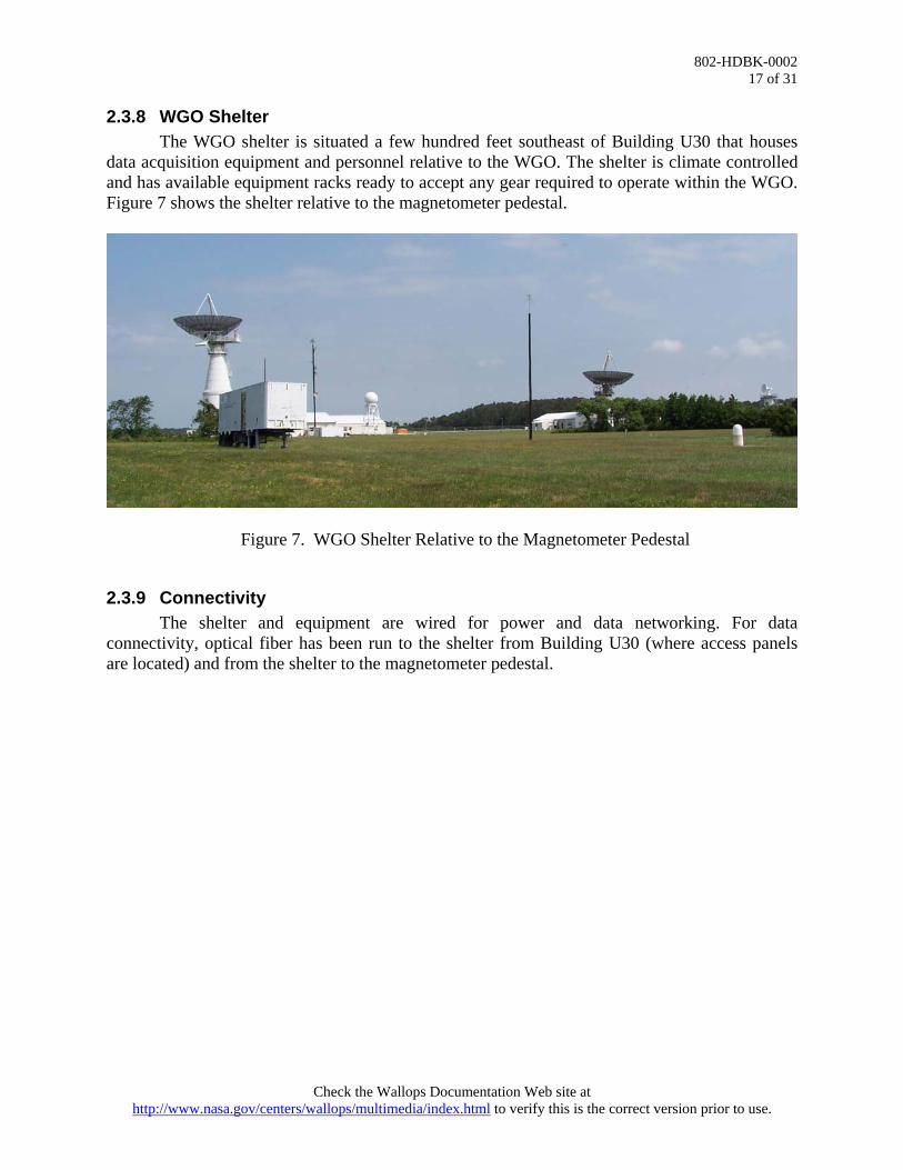
2.3.8 WGO Shelter The WGO shelter is situated a few hundred feet southeast of Building U30 that houses
data acquisition equipment and personnel relative to the WGO. The shelter is climate controlled and has available equipment racks ready to accept any gear required to operate within the WGO. Figure 7 shows the shelter relative to the magnetometer pedestal.
Figure 7. WGO Shelter Relative to the Magnetometer Pedestal
2.3.9 Connectivity The shelter and equipment are wired for power and data networking. For data
connectivity, optical fiber has been run to the shelter from Building U30 (where access panels are located) and from the shelter to the magnetometer pedestal.
Check the Wallops Documentation Web site at http://www.nasa.gov/centers/wallops/multimedia/index.html to verify this is the correct version prior to use.

802-HDBK-0002 18 of 31
Section III: Facilities and Capabilities 3.1 Wallops Flight Facility Runways
The Wallops UAV runway is located on the south end of Wallops Island (Figure 8). The runway is 1,500 feet long with 50-foot wide asphalt and 20-foot wide grass landing strips. Commercial UAV manufacturers and other users conduct product trials, pilot training, and science missions from the runways.
Figure 8. UAV Runway on Wallops Island
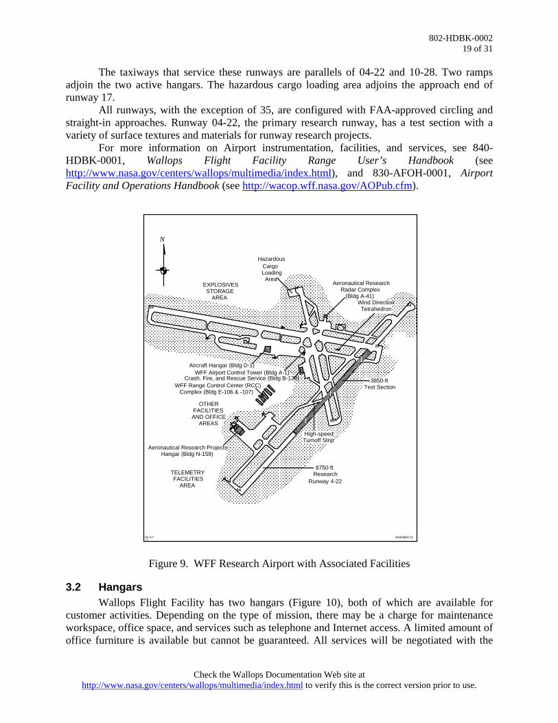
The WFF Research Airport is located on the Main Base. Figure 9 illustrates the Research Airport and associated facilities. There are three runways, two taxiways, three ramps, and one hazardous cargo loading area in active service. The runway dimensions are:
• 10-28 – 8,005 feet by 200 feet • 04-22 – 8,750 feet by 150 feet • 17-35 – 4,810 feet by 150 feet
Check the Wallops Documentation Web site at http://www.nasa.gov/centers/wallops/multimedia/index.html to verify this is the correct version prior to use.
802-HDBK-0002 19 of 31
The taxiways that service these runways are parallels of 04-22 and 10-28. Two ramps adjoin the two active hangars. The hazardous cargo loading area adjoins the approach end of runway 17. All runways, with the exception of 35, are configured with FAA-approved circling and straight-in approaches. Runway 04-22, the primary research runway, has a test section with a variety of surface textures and materials for runway research projects. For more information on Airport instrumentation, facilities, and services, see 840-HDBK-0001, Wallops Flight Facility Range User’s Handbook (see http://www.nasa.gov/centers/wallops/multimedia/index.html), and 830-AFOH-0001, Airport Facility and Operations Handbook (see http://wacop.wff.nasa.gov/AOPub.cfm).
10
17
22
28
35
04
N
RUH940711
EXPLOSIVES STORAGE
AREA
Hazardous Cargo Loading
AreaAeronautical Research
Radar Complex (Bldg A-41)
Aircraft Hangar (Bldg D-1)WFF Airport Control Tower (Bldg A-1)
Crash, Fire, and Rescue Service (Bldg B-129)WFF Range Control Center (RCC)
Complex (Bldg E-106 & -107)
Aeronautical Research Projects Hangar (Bldg N-159)
TELEMETRY FACILITIES
AREA
High-speed Turnoff Strip
Wind Direction Tetrahedron
OTHER FACILITIES
AND OFFICE AREAS
3850-ft Test Section
8750-ft Research
Runway 4-22
02-17-95
Figure 9. WFF Research Airport with Associated Facilities
3.2 Hangars Wallops Flight Facility has two hangars (Figure 10), both of which are available for customer activities. Depending on the type of mission, there may be a charge for maintenance workspace, office space, and services such as telephone and Internet access. A limited amount of office furniture is available but cannot be guaranteed. All services will be negotiated with the
Check the Wallops Documentation Web site at http://www.nasa.gov/centers/wallops/multimedia/index.html to verify this is the correct version prior to use.

802-HDBK-0002 20 of 31
Aircraft Office before beginning mission activities. Certain institutional services, such as janitorial, will also be negotiated prior to mission startup.
Figure 10. Wallops Flight Facility Hangars
3.3 Fuel Farm The Wallops Fuel Farm contains five 20,000-gallon underground JP fuel tanks and pumping station; two 10,000-gallon JPTS underground tanks; one 10,000-gallon “off spec” underground tank; and one 12,000-gallon spill containment tank. Fuel is a billable commodity.
3.4 Control Tower A FAA-certified VFR control tower operates on 126.5/394.3 MHz. The Control Tower is manned from 0700 to 1730 Monday through Friday, excluding holidays, and at other times to support specific missions. FAA AC No. 90-42, Traffic Advisory Practices at Airports Without Operating Control Towers, is in effect during non-tower operating hours.
3.5 Range Control Centers The focal point for all Research Range operations is the Range Control Center located on the Main Base. Data from the range support instrumentation (e.g., closed circuit TV, radar and TM data) are acquired, processed, and made available for video display throughout the facility. This data assimilation, in conjunction with communications and command links, facilitates the coordination control and safe conduct of WFF missions. The Aeronautical Projects Control Room (APCR) provides visual observation of the Research Airport, including research runway 04-22 and aeronautical project activities in the surrounding area. The APCR has mission controller consoles, which provide communications and data display for monitoring and control of aeronautical projects. The UAV runway is controlled remotely from one of the buildings on the Island.
3.6 Telemetry Facilities Telemetry (TM) facilities at the Wallops Research Range include a variety of antennas, receivers, and display instrumentation systems. Command uplink and metric tracking capabilities are also available. Post-flight telemetry data can be distributed via magnetic tape, CD-ROM, and magneto-optical disks. See 840-HDBK-0001 for specifications on the TM facilities available at Wallops.
Check the Wallops Documentation Web site at http://www.nasa.gov/centers/wallops/multimedia/index.html to verify this is the correct version prior to use.
802-HDBK-0002 21 of 31
3.7 Radar Facilities Radar systems perform tracking and surveillance functions. Tracking radar systems provide accurate velocity and positional data of launch vehicles, balloons, satellites, and aircraft. The Research Range has three fixed and four mobile tracking radar systems. The fixed radar systems are located at the Research Airport, on the Mainland, and on Wallops Island. Surveillance radars provide range surveillance to detect water surface and airborne targets. The Mariners Pathfinder on Wallops Island and the ASR-7 are fixed surveillance radar systems that support operations on the Research Range. The AN/APS-143 is an airborne surveillance radar system that is installed on contract aircraft in partnership with NAS Patuxent River. Specifications for all radar systems at Wallops can be found in 840-HDBK-0001.
3.8 Frequency Utilization and Management The WFF Test Director is responsible for the operational control of the RF spectrum at
Wallops. Frequency utilization and management policies and procedures applicable to all range user activities at Wallops are detailed in 800-HDBK-0001, Wallops Flight Facility Frequency Utilization Management Handbook.
3.9 Weather Forecast Office The Weather Forecast Office provides daily forecasts and other meteorological
information in support of all WFF activities, including targeted forecasts upon request. National, regional, and local weather data are available. Data sources include the Leading and Environmental Display System (LEADS); several lightning detection systems; field mills, which measure lightning potential; and a full complement of local surface instruments to measure wind, temperature, pressure, dew point and cloud height.
A daily forecast briefing covering the upcoming 12 hours is broadcast at 10 a.m. over the WFF closed circuit television. A forecast of the upcoming 36 hours is prepared in the afternoon and is available from the Weather Forecast Office. Weather briefings are available by telephone upon request, and the daily 12- and 36-hour forecasts are placed on a telephone recording (extension 2291) at 10 a.m. and 1 p.m.
Other weather and video switching network information is available on the WFF closed circuit television network:
• Weather radar display originating from the National Weather Service (NWS) radar • Local weather conditions, including upper winds, based on sensors at WFF • National Lightning Detection Network displays The following meteorological facilities support launch operations: • Fixed, balloon-borne, and optical sensors are available for obtaining atmospheric
data. • Current weather data from weather sensors on the Main Base and Wallops Island are
continuously displayed on the local WFF closed circuit TV system, and the data can be made available remotely via modem interfaces.
• An Ionosphere Sounding Station provides detailed data on the ionosphere characteristics.
Check the Wallops Documentation Web site at http://www.nasa.gov/centers/wallops/multimedia/index.html to verify this is the correct version prior to use.

802-HDBK-0002 22 of 31
• Lightning detection systems display lightning conditions locally and over the United States.
• An Electric Field Measurement System aids in determining the probability of and detection of local lightning activity.
• Indigenous WFF radar data from the ASRF and other Instrumentation Sciences radars are also available in the Weather Office.
3.10 Engineering The Mechanical Systems Branch provides mechanical systems mission design and
implementation for suborbital and special orbital projects and for Earth and space science instrument design and development activities at the Wallops Flight Facility. Personnel serve in the Product Design Lead role on key projects and technology development efforts and also provide technical expertise and implementation of integration, testing and launch operations. The Wallops Electrical Engineering Branch is responsible for conception, analysis, design, development, validation, and implementation of electrical/electronic, RF, microwave, and millimeter wave components and systems, which include flight and ground instrumentation, communication, and radar components and systems. The branch supports Wallops ELVs, sounding rockets, aircraft, balloons, satellites, Shuttle payloads, ocean-borne payloads, and support systems.
The GNC and Mission Systems Engineering Branch provides skills, vision and leadership in guidance, navigation and control systems, engineering, GNC related operations, and mission analysis. Technical disciplines include flight dynamics, propulsion, flight mechanics, guidance, navigation and control engineering for space systems, experiments, suborbital missions, and launch vehicles. The branch also provides Mission Systems Engineering support for science missions and technology development efforts.
The Wallops Systems Software Engineering Branch (WSSEB) develops integrated systems for real-time mission support; performs prototyping in collaboration with other NASA and government organizations, universities, and commercial partners; and develops test beds/simulators to provide proof of concepts in an operational environment. The WSSEB analyzes, designs, tests, develops, and integrates unique software, hardware, commercial off-the-shelf (COTS), and data systems solutions to meet customer needs.
3.11 Fabrication Facilities Wallops Flight Facility has a fully equipped machine shop that can provide electronic, electrical, and mechanical support (see Figure 11). The 26,000 square foot machine shop includes a large selection of Computer Numerically Controlled (CNC) mills and lathes, manual machines, sheet metal fabrication, welding, and heat-treating facilities. Capabilities include full CAD/CAM implementation in developing and fabricating mechanical systems, optical instrumentation, and payload components for flight research.
Check the Wallops Documentation Web site at http://www.nasa.gov/centers/wallops/multimedia/index.html to verify this is the correct version prior to use.

802-HDBK-0002 23 of 31
Figure 11. View of Machine Shop Floor The machine shop includes mechanical technician laboratories for assembly of scientific payloads. While the facility primarily supports the Sounding Rocket Program, it regularly supports other NASA and reimbursable projects. A more comprehensive description of mechanical and electrical fabrication capabilities is available in 810-HB-SRP, Sounding Rocket Program Handbook, available online at http://www.nasa.gov/centers/wallops/multimedia/index.html.
3.12 Environmental Test Facilities Environmental testing of complete payloads, subassemblies, and components verifies flight readiness when exposed to an intended flight environment. Specialized facilities for environmental testing are available in the Environmental Testing Laboratory adjacent to the Payload Integration Laboratory for convenience in payload handling and logistics. Additional engineering test facilities are available in the Balloon R&D Laboratory and Multi-port Payload Processing Center. The Magnetic Calibration Facility and the EMI/RFI chamber are available to customers. The Dynamic Balance Facility is on Wallops Island. A more detailed discussion of these facilities is available in 802-HDBK-0001.
3.13 Science Facilities The Hydrospheric and Biospheric Sciences Laboratory, working within the Earth-Sun
Exploration Division at GSFC, conducts theoretical, experimental and applied research in the oceanic, atmospheric, and terrestrial sciences. Instrumentation Sciences Branch personnel at Wallops design, fabricate and operate both remote and in-situ sensing instruments for aircraft, balloons, rockets, and UAVs. They plan and conduct laboratory and field measurements to improve the fundamental knowledge of Earth sensing and to evaluate sensor systems as well as
Check the Wallops Documentation Web site at http://www.nasa.gov/centers/wallops/multimedia/index.html to verify this is the correct version prior to use.

802-HDBK-0002 24 of 31
quantify and demonstrate system performance. A more detailed discussion of various instruments and systems available for experiments is available at http://science.wff.nasa.gov/.
3.14 GPS Simulator Facility The GPS Simulator Facility is comprised of a 4-output Spirent GSS GPS simulator
capable of reproducing the radio frequency (RF) signal that would be received by a GPS receiver as it travels any trajectory at any time, with parameters such as signal strength, multipathing, antenna patterns controllable for testing of navigation and attitude receivers; a single output Spirent GSS GPS receiver programmable and transportable for use in the field; and a Navigation Laboratories Tapestry GPS/IMU simulator.
These simulators may be controlled remotely to produce hardware-in-the-loop, Monte Carlo simulations of GPS and IMU for satellites and launch vehicle trajectories. No other civilian installation has the capability to develop and test sensors in this manner. Current users include the Sounding Rocket and Scientific Balloon programs and the Autonomous Flight Safety System. The GPS Simulator Facility can be configured for stand-alone operation or used with the range and mobile range simulators.
Check the Wallops Documentation Web site at http://www.nasa.gov/centers/wallops/multimedia/index.html to verify this is the correct version prior to use.

802-HDBK-0002 25 of 31
Section IV: Institutional Services 4.1 Crash Fire and Rescue (CFR)
Crash Fire and Rescue provides a variety of emergency response services, including fire fighting, emergency medical services (EMS), and fire safety inspection and prevention. The Main Base and Island fire stations support all normal aircraft activities and generally provide mutual aid support to include HazMat, water supply, rescue, and EMS operations. The Emergency Operations Center (EOC) is manned at all times and serves as the communications and alarm center for all WFF emergency services. The EOC operates the UNICOM Control in an advisory capacity only for the airport when the control tower is not active (see 830-AFOH-0001 and FAA AC No. 90-42).
4.2 Security Wallops Flight Facility and Research Range maintains 24-hour security for all facilities.
Personnel without current security badges will not be allowed access to the Main Base, the Mainland, or the Island. All visitors must check in with Security at the Main Gate. Foreign nationals must obtain prior approval to visit at least 20 working days (4 weeks) in advance of a visit of 30 days or less and 2 calendar months in advance for an assignment over 30 days. All visits to Wallops should be coordinated with the Project Manager or customer contact. More information regarding security requirements can be found in NPR 1620.1, Security Procedures and Guidelines.
4.3 Metrology Laboratory Wallops Flight Facility maintains a Metrology Laboratory equipped to perform repair and calibration of test instruments. Customer-furnished equipment is calibrated and certified at this facility. The equipment in the standards laboratory is traceable to the National Institute of Standards and Testing (NIST). These standards are part of a mandatory recall program for recalibration and certification.
4.4 Chemical Laboratory Wallops Flight Facility maintains a chemical laboratory, which performs aviation fuel analysis in support of scientific aircraft and oil analysis in support of radar installations. The lab also performs wastewater analysis for the facility.
4.5 Environmental The Wallops Environmental Office serves as the clearinghouse for National
Environmental Policy Act (NEPA) compliance at Wallops. Services and responsibilities include hazardous waste management; pollution prevention; oil spill prevention and response; storage tank management; air pollution control; water pollution control; historical and archeological preservation; and environmental consulting. In most cases, Wallops has approved environmental documentation covering range users’ activities at WFF. The Site-Wide Environmental Assessment, Wallops Flight Facility, Virginia, provides the required environmental documentation for all Wallops “in-house” activities and also provides the required documentation for many range users’ activities (see http://www.nasa.gov/centers/wallops/multimedia/index.html). Early in the project, the Project Manager will discuss environmental requirements with the range user to identify potential
Check the Wallops Documentation Web site at http://www.nasa.gov/centers/wallops/multimedia/index.html to verify this is the correct version prior to use.

802-HDBK-0002 26 of 31
environmental issues. Wallops Environmental Office personnel will make a determination of any formal documentation requirements.
4.6 Shipping/Receiving Various shipping services are available, including United Parcel Service, Federal
Express, and the U.S. Postal Service. The nearest commercial airfreight service is at the Salisbury-Wicomico County Regional Airport, Salisbury, Maryland. The range user should use the following information when mailing correspondence or shipping equipment for official project business:
Mail Address: Name/GSFC Code Number NASA Goddard Space Flight Center Wallops Flight Facility Wallops Island, VA 23337 USA Freight Destination Address: Name/GSFC Code Number C/O Receiving Officer NASA Goddard Space Flight Center Wallops Flight Facility Wallops Island, VA 23337 USA Hazardous materials require special handling. See 840-HDBK-0001 for instructions and
references.
4.7 Motor Freight Truck Service Most cargo and freight are received at WFF Main Base; however, construction material is
delivered to the site, and commercial shipments may be received directly by commercial users. Inbound shipments of Class “A” and “B” explosives and other designated hazardous
materials require advance notice prior to arrival. The delivering carrier’s representative should provide advance notice by telephone to explosives handling personnel (757-824-1433). The explosives handling personnel will furnish onsite escort, unloading, inspection, and shipment acceptance.
Normal receiving hours are 0800 to 1430 (for truckloads) and 0800 to 1600 (for partial loads), Monday through Friday, excluding holidays.
4.8 Air Cargo Air cargo deliveries require special consideration and must be discussed with the
assigned Project Manager and/or the Airport Manager. GSFC/WFF Airport Manager Phone (757) 824-1240 Fax (757) 824-1250
Check the Wallops Documentation Web site at http://www.nasa.gov/centers/wallops/multimedia/index.html to verify this is the correct version prior to use.

802-HDBK-0002 27 of 31
4.9 Customs International shipments should clear U.S. Customs before arrival at WFF. Arrangements
for shipments directly from overseas into WFF must be coordinated and approved by U.S. Customs prior to shipment.
4.10 Post Office A United States Post Office is located on the Main Base. The address is Wallops Island,
VA 23337 USA.
4.11 Material Handling Equipment A variety of material handling equipment is available at Wallops, including forklifts, overhead hoists, cranes, basket trucks, and material moving equipment. Additional information on types of material handling equipment can be found in 840-HDBK-0001.
4.12 Warehousing and Hazardous Materials Storage Warehouse space is available on a limited basis. The customer should notify the Wallops point of contact in advance of the type and amount of storage required, including chemical, explosive, and inert hardware storage. All hazardous material must be packaged to conform to applicable Department of Transportation regulations. A Material Safety Data Sheet (MSDS) must accompany all hazardous materials shipped to Wallops. For more information regarding hazardous materials shipment and storage, see 810-HB-SRP and 840-HDBK-0001.
Radioactive sources require approval from the GSFC Safety and Environmental Office prior to arrival. The range user must provide the proper forms requesting the use of a radioactive material at WFF, including license information, to the Project Manager at least 90 days prior to the shipment/arrival of the source. GPG 1860.1, Ionizing Radiation Protection, defines procedures and provides the needed forms. This document may be seen online at http://msc-docsrv.gsfc.nasa.gov/GDMS_docs/GPG1000/GPG-1860.1-.pdf.
4.13 Fire Protection There are two fire stations at Wallops, one on the Main Base and one on Wallops Island. Both stations are manned 24 hours a day by fully trained firefighters and emergency medical technicians. Each station is equipped to meet Wallops emergency response requirements. If both stations are called out, any aircraft or project requiring Crash Fire and Rescue services will be halted for the duration.
4.14 Medical Facilities The Health Unit located on the Main Base is available for limited medical services in the
event of an emergency during working hours. Emergency medical technicians from the fire station are available 24 hours a day. Ambulance services are also available. The Northampton-Accomack Memorial Hospital is approximately 40 miles south in Nassawadox, Virginia. The other local hospital is the Peninsula Regional Medical Center located approximately 40 miles north in Salisbury, Maryland.
4.15 Communications Telephone service is provided through the Federal Telecommunications System (FTS-2000) for official U.S. Government business. Long-distance billing can be supported by
Check the Wallops Documentation Web site at http://www.nasa.gov/centers/wallops/multimedia/index.html to verify this is the correct version prior to use.

802-HDBK-0002 28 of 31
telephone credit cards or prorated FTS accounts for non-Government projects. Fax service is available. Modem support for range user computers may be provided through the digital PBX system. The WFF operator is available during normal working hours at (757) 824-1000. The Outsourcing Desktop Initiative for NASA (ODIN) contractor can provide Internet access on a month-to-month basis. There are no restrictions on pagers and cell phones. Teleconferencing and video teleconferencing services are available through the customer’s sponsor. Portable audio conferencing equipment is also available.
4.16 Library NASA maintains a scientific and technical library on the Main Base. Local and national newspapers and periodicals are available on site, as well as computers with access to the Internet. The library is open from 8:00 a.m. to 4:30 p.m. Monday through Friday.
4.17 Print Shop The Print Shop features a variety of duplicating equipment that produces a wide range of products from door signs to Braille documents. The state-of-the-art high-speed duplicator produces copies quickly and with special features such as storing documents for reprints and simultaneous mail merging. Customers can transmit their documents electronically rather than providing a "camera ready" hard copy. Moreover, there is a wide range of binding options for documents. Not all services are available at Wallops, but the Print Shop can arrange to have those services performed at the Greenbelt location. Information on services offered can be viewed at http://tims.gsfc.nasa.gov/.
4.18 Photo Services Photo Services supports technical, scientific, and administrative organizations at Wallops. The newly established Digital Imaging Facility complements the traditional photographic services and provides many new capabilities in-house. Photo Services also offers a videotaping capability, including video production and tape duplication, as well as distribution and life cycle management of finished programs. Many more services and areas of support provided by the Photographic Services Team, such as photographic stills and high-speed video tracking, can be found at http://tims.gsfc.nasa.gov/.
4.19 NASA Federal Credit Union The NASA Federal Credit Union maintains an office on Wallops Main Base. Personnel employed at GSFC may become members of the credit union. There is an ATM open 24 hours a day. More information on credit union services can be seen at http://www.nasafcu.org.
4.20 Cafeteria and Dormitories The Wallops Exchange and Morale Association (WEMA) manages the cafeteria and dormitories. The cafeteria serves breakfast and lunch Monday through Friday, except holidays. Dormitory rooms are rented on a space-available basis. Morale activities can be viewed on base at http://www.wff.nasa.gov/wemamac.
Check the Wallops Documentation Web site at http://www.nasa.gov/centers/wallops/multimedia/index.html to verify this is the correct version prior to use.

802-HDBK-0002 29 of 31
4.21 Fitness Facility Wallops maintains a fitness facility, which includes a gymnasium, weight room, Nautilus equipment room, locker rooms, and saunas. Guest memberships are available. The Morale Activities Committee (MAC) manages the fitness facility.
4.22 Public Affairs Support The Wallops Public Affairs Office (PAO) is available to support range users with media
and guest relations operations. The PAO can set up Web casts of missions and can accommodate groups that want to transmit broadcasts from Wallops using a small local radio station that provides launch commentary for local listeners. Initial requests for PAO support can be made through the Project Manager or customer’s representative.
Check the Wallops Documentation Web site at http://www.nasa.gov/centers/wallops/multimedia/index.html to verify this is the correct version prior to use.

802-HDBK-0002 30 of 31
The page intentionally left blank.
Check the Wallops Documentation Web site at http://www.nasa.gov/centers/wallops/multimedia/index.html to verify this is the correct version prior to use.

802-HDBK-0002 31 of 31
Appendix: References (listed in order of appearance)
1. Commercial Space Launch Act, Public Law 98-575
2. 802-HDBK-0001, Doing Business at Wallops Flight Facility: A Customer Guide
3. 840-HDBK-0001, Wallops Flight Facility Range User’s Handbook
4. 830-AFOH-0001, Airport Facility and Operations Handbook
5. FAA AC No. 90-42, Traffic Advisory Practices at Airports Without Operating Control Towers
6. 800-HDBK-0001, Wallops Flight Facility Frequency Utilization Management Handbook
7. 810-HB-SRP, Sounding Rocket Program Handbook
8. NPR 1620.1, Security Procedures and Guidelines
9. Site-Wide Environmental Assessment, Wallops Flight Facility, Virginia
10. GPG 1860.1, Ionizing Radiation Protection
Check the Wallops Documentation Web site at http://www.nasa.gov/centers/wallops/multimedia/index.html to verify this is the correct version prior to use.