Embed Size (px)
Citation preview

Wall-Mount Transfer SwitchesProduct Focus
Automatic Transfer Switches

Wall-MountTransferSwitchesIntroduction
A History of Great Service, Reliability and Support
For over a century, Eaton has focused on providingquality power-centric products and services. Intoday’s business environment, customers like you aredriving our transformation from a leading global elec-trical components provider into a customer-centricsolutions partner who understands your business. We do this through in-depth collaboration with customers and subject matter experts studying theissues inherent to the electrical power distributionand control systems. The application section providesyou with a broad look at the solution sets that areavailable or in development in order to help addresscritical electrical system problems affecting mostbusinesses through an integrated solutions design center.
For emergency service, startup and application support, call Eaton - Electrical Services & Systems at 1-800-498-2678.
The Best in Reliability OffersThe Best in Transfer Switches
As a premier industrial manu-facturer, Eaton’s electrical business is one of the world’sleading suppliers of electricalcontrol products and power distribution equipment withyearly sales of over $2.5 billion.Eaton’s electrical productsinclude a complete line of lowand medium voltage assem-blies from substations,switchgear and panelboards to loadcenters, transformersand safety switches. Theseproducts are used whereverthere is a demand for electricalpower in residences, high-riseapartment and office buildings,commercial sites, hospitals and factories.
Automatic Transfer Switches
Eaton is one of the pioneeringelectrical manufacturers andhas been focused on providingreliable backup power systemswith transfer switch equipmentfor over 75 years. The automat-ic transfer switches provide asafe and reliable means to auto-matically start your generator,and transfer loads to a standbypower source when normalpower is unavailable. Eatonoffers three reliable and sophis-ticated transfer switch optionsfor you to choose from —Contactor-Based, Molded Caseand Circuit Breaker styleswitches.
24-Hour Automatic Protection
Power outages due to badweather or utility failure havegrown increasingly costly andmore disruptive to businessesand homeowners. A backuppower system will keep yourcomputers, security system,heating or refrigeration system,cash registers, home healthcare equipment, or any systemthat uses electric power, energized and operational.
Along with your generator, aCutler-HammerT AutomaticTransfer Switch from Eaton willprovide a reliable and safe back-up power system for your business or home.
Security• Prevent loss of power
during a utility power failure.
• Prevent personal injury andgenerator damage.
• Prevent the loss of computer data from extended outages.
• Prevent property loss due to freezing or loss of refrigeration.
• Prevent accidental connec-tion of the generator to the utility.
Service Entrance EquipmentEaton service equipment ratedtransfer switches with integralovercurrent protection may beinstalled at the point of serviceentrance without the need forseparate upstream disconnectdevices and their respectivepower interconnections.
Benefits• Combined service
disconnect, overcurrent protection and automatictransfer switch reducesoverall equipment and installation costs.
• Fewer components andpower connections reducemaintenance requirements.
2 EATON CORPORATION Wall-Mount Transfer Switches — Introduction

Residential Contactor-Based Transfer SwitchStandard Features• Proven, highly reliable
microprocessor-based logic provides full automatic operation.
• 100 and 200 ampere ratingsfor use on 120/240 Vac and208 Vac, 60 Hz single-phasesystems only.
• Fixed time delays providesimple operation — without user programming.
• Four separate time delays:
• Engine start: 3 seconds
• Normal to emergency:selectable 2 or 15 seconds
• Emergency to normal: 5 minutes
• Engine cooldown: 1 minute fixed
• Automatic Plant Exerciserwith selectable day, off, 7,14, 28, 15 minutes run time,day, no load.
• Indoor/outdoor NEMAT 1and 3R enclosures.
• Delivered from the factorycompletely assembled,prewired and tested.
• Only four connections forthe installer to complete:utility power, generatorpower, load circuits andengine start.
• Hinged door with lockable cover.
• ULT 1008 listed.
Wall-MountTransferSwitchesResidentialContactor-Based
3EATON CORPORATION Wall-Mount Transfer Switches — Residential Contactor-Based
RESIDENTIAL CONTACTOR-BASED TRANSFER SWITCHES SEQUENCE OF OPERATION
Transfer Switch Allows Generator to Cool Downfor 5 Minutes and then Sends “Stop” Signal
to Generator
Utility Fails for Longer than10 Seconds
Wait 3 Seconds for Generator to Warm Up
Transfer Switch Watches for Utility Power to Return
Wait 7 Minutesfor Utility Power
to Become Constant
Transfer SwitchConnects
House Circuitsto Utilities
Transfer SwitchConnects
House Circuitsto Generator
Transfer SwitchSends “Start”
Signal to Electric StartGenerator
Utility Power OKHouse Circuits Connected to
Utility
Utility PowerReturns
GeneratorPower OK

EATON CORPORATION Wall-Mount Transfer Switches — Residential Contactor-Based4
BA
C
TopView
FrontView
RESIDENTIAL CONTACTOR-BASED TRANSFER SWITCH DIMENSIONS IN INCHES (MM), WEIGHTS IN POUNDS (KG), POWERCABLE CONNECTIONS AND WITHSTAND AND CLOSE-ON RATINGS
Switch Rating Amperes Service Entrance Amperes
Dimensions 100 200 100 200
A 5.35 (135.9) 5.35 (135.9) 5.35 (135.9) 5.35 (135.9)
B 14.46 (367.3) 14.46 (367.3) 14.46 (367.3) 14.46 (367.3)
C 16.76 (425.7) 29.14 (740.2) 29.20 (741.7) 34.20 (868.7)
Weights 26 (11.8) 38 (17.3) 38 (17.3) 40 (18.2)
Wire Size Range (AWG) (1) #14 to 2/0 (1) #4 to 300 (1) #14 to 2/0 (1) #4 to 300
Withstand Rating 22,000 25,000 10,000 10,000
RESIDENTIAL CONTACTOR-BASED TRANSFER SWITCH
RLC 1 S X J 2 0100 W S U
Type
RLC = Residential Controller
1 = ATC-100 Controller Rating
X = StandardE = Service Entrance
Transition
S = Standard Transition
Mounting
J = Fixed Mounted
Number of Poles
2 = 2-Pole
Certification
U = UL 1008 ListedEnclosure
S = NEMA 1R = NEMA 3R
Voltage
B = 208/120 VacW = 240/120 Vac
Amperes
0100 = 100 A0200 = 200 A
RESIDENTIAL CONTACTOR-BASED TRANSFER SWITCH CATALOG NUMBERING SYSTEM

5EATON CORPORATION Wall-Mount Transfer Switches — Residential Contactor-Based
WALL-MOUNT CONTROLLERS
Description ATC-100 ATC-300 ATC-600
System Application Voltage 120/240 V, 208 V Single-Phase Up to 600 Vac Up to 600 Vac
Voltage Specifications
Voltage Measurements of: Source 1 and 2 Source 1 and 2 — Source 1, 2 and Load — VAB, VBC and VCA VAB, VBC and VCA
Voltage Measurement Range 120 – 480 Vac 0 – 790 Vac rms 0 – 790 Vac rms Operating Power 95 Vac – 145 Vac 65 Vac – 145 Vac 65 Vac – 145 VacFrequency Specifications
Frequency Measurements of: Source 2 Source 1 and 2 Source 1 and 2Frequency Measurement Range 50 – 60 Hz 40 – 70 Hz 40 – 70 HzEnvironmental Specifications
Operating Temperature Range -20 to +70ºC -20 to +70ºC -20 to +70ºCStorage Temperature Range -30 to +85ºC -30 to +85ºC -30 to +85ºCOperating Humidity 0 to 95% Relative Humidity 0 to 95% Relative Humidity 0 to 95% Relative Humidity (Non-condensing) (Non-condensing) (Non-condensing) (Non-condensing)Operating Environment Resistant to Ammonia, Resistant to Ammonia, Resistant to Ammonia,
Methane, Nitrogen, Hydrogen, Methane, Nitrogen, Hydrogen, Methane, Nitrogen, Hydrogen, and Hydrocarbons and Hydrocarbons and Hydrocarbons
Front Panel Indication
Mimic Diagram with LED Indication Unit Status. Source 1 and 2 — Unit Status. Source 1 and 2 — Automatic, Test and Program Available and Connected (5 Total) Available and Connected (5 Total) Mode. Source 1 and 2 —
Available, Connected and Preferred. Load Energized (10 Total)
Main Display n/a LCD-Based Display LED Display Display Language n/a English, French EnglishCommunications Capable n/a n/a PONI/INCOMEnclosure Compatibility NEMA 1 and 3R NEMA 1, 12 and 3R, NEMA 1, 12, 3R and 4X UV
UV Resistant Faceplate Resistant FaceplateOperating Environmental Range Operation -20°C to +70°C, Operation -20°C to +70°C, Operation -20°C to +70°C,
Storage -30°C to +85°C, Storage -30°C to +85°C, Storage -30°C to +85°C,Humidity 0% to 95% Relative Humidity 0% to 95% Relative Humidity 0% to 95% Relative(Non-condensing) (Non-condensing) (Non-condensing)
Programming Selections
Time Delay Normal to Emergency Selectable 2 or 15 Seconds 0 – 1800 Seconds 0 – 1800 SecondsTime Delay Emergency to Normal 5 Minutes — Fixed 0 – 1800 Seconds 0 – 1800 SecondsTime Delay Engine Cooldown 1 Minute — Fixed 0 – 1800 Seconds 0 – 1800 SecondsTime Delay Engine Start 3 Seconds — Fixed 0 – 120 Seconds 0 – 120 SecondsTime Delay Neutral n/a 0 – 120 Seconds 0 – 120 Seconds or Based on
Load Voltage Decay of 2% – 30% of Nominal
Time Delay Source 2 Fail n/a 0 – 6 Seconds 0 – 6 SecondsTime Delay Voltage Unbalance n/a 10 – 30 Seconds n/aVoltage Unbalance 3-Phase n/a 0 or 1 (1 = Enabled) —% of Unbalanced Voltage Dropout n/a 5% – 20% (DO) n/a
Dropout -2% – 3% (PU)Phase Reversal 3-Phase n/a OFF, ABC, CBA n/aIn-Phase n/a 0 or 1 (1 = Enabled) n/aLoad Sequencing n/a n/a Up to 10 Devices (via Sub-network)Pre-Transfer Signal n/a 1 – 120 Seconds 0 – 120 Seconds
(Form C Contact) Up to 10 Devices (via Sub-network) Plant Exerciser Selectable Day, Off, 7, 14, 28 Selectable — Off, Daily or 7, 14, 28 Selectable — Disabled or 7
Day Interval, 15 Minutes Run Time, Day Intervals, 0 – 600 Minutes, Day Interval, 0 – 600 Minutes,No Load Load or No Load Load or No Load
Preferred Source Selection n/a n/a Source 1 or 2 or NoneCommitment to Transfer in TDNE n/a n/a Enabled or DisabledRe-Transfer Mode n/a n/a Automatic or ManualAuto Daylight Savings Time Adjustment n/a 0 or 1 (1 = Enabled) —System Selection Utility/Generator or Dual Utility Utility/Generator or Dual Utility Utility/Generator or Dual Utility or
Dual Generator
Note: Features are order specific. Not all features are supplied as standard.


7EATON CORPORATION Wall-Mount Transfer Switches — Contactor, Molded Case and Circuit Breaker Design
Product Description
Eaton’s Cutler-Hammer Wall-Mount Transfer Switchesare designed for a variety ofstandby power applications forcritical loads. They provide flexi-bility, reliability and value in acompact package. In the eventof a primary power sourceinterruption, a transfer switchprovides an effective means totransfer the load circuits to analternate power source whilereducing the possibility of injuryor property damage.
Wall-MountTransferSwitchesContactor,Molded Caseand CircuitBreaker Design
Wall-Mount Transfer Switchesmeet or exceed all industrystandards for endurance, relia-bility and performance. Theyare listed under UnderwritersLaboratories UL 1008 Standardfor Transfer Switch Equipmentand optionally available as suit-able for emergency and stand-by systems as defined in NFPA99 for health care facilities.
ATC-300 Automatic TransferSwitch shown above.
Electrical Ratings• Molded case and circuit
breaker 30 – 1000 amperes.
• Contactor 100, 200, 320,400 and 600 amperes.
• 2-, 3- or 4-poles.
• Up to 600 Vac, 50/60 Hz.
• NEMA 1, 3R, 12, open.
• Suitable for emergency andstandby systems (all loads).
• UL 1008 listed.
• CSAT C22.2 No. 178 certified.
Industrial Design Highlights• Double-throw, mechanically
interlocked transfer mechanism.
• High withstand and closing ratings.
• Seismic Zone 4 qualified(BOCAT, CBC, IBC, UBCT).
Standard Features• Auxiliary relay contacts:
• Source 1 present 2NO and 2NC
• Source 2 present 2NO and 2NC
• Switch position indication contacts:
• Source 1 position 1NO and 1NC
• Source 2 position 1NO and 1NC
• Source 1 and Source 2 sensing:
• Undervoltage/underfrequency
• Overvoltage/overfrequency
• 3-phase rotation protection
• 3-phase voltage unbalance/loss
• Pre-transfer signal contacts1NO/1NC.
• Go to Emergency (Source 2).
• Seven field-programmabletime delays.
• LCD-based display for programming, system diagnostic and HELPmessage display.
• Mimic diagram with sourceavailable and connected LED indication.
• Time-stamped history log.
• System test pushbutton.
• Programmable plant exerciser — OFF, daily, 7,14, 28-day interval selec-table run time 0 – 600 minutes no load/load with fail-safe.
• Safe manual operation underfull load with permanentlyaffixed operating handle. 1
Optional Features• Suitable for use as service
equipment in the standardenclosure size. 1
• Available TVSS for power/controller, engine start circuit, phone and cable connections.
• Integrated distribution panels. 1
• Field-selectable multi-taptransformer panel permitsoperation on a wide range of system voltages.
• Integral overcurrent protection. 1
• Space heater with thermostat.
• Ammeter — load side.
• Stainless steel cover for controller.
1 Not available on ContactorTransfer Switch.
UL 1008 WITHSTAND AND CLOSE-ON RATINGS (KA)
Specific Breaker RatingMax. Circuit
UL 1008 Breaker Max. AmpsContactor Ampere Size at 480 Style Rating Amperes Vac (UL)
61WNU-3FD 100 125 30,000
64WNU-3FD 200 250 50,000
64WNU-3FD 320 600 50,000
64WNU-3FD 400 600 50,000
66WNU-3FD 600 800 65,000
Contactor-Based Transfer Switch
TERMINAL DATA OPTIONS FOR POWER CABLE CONNECTIONS
Switch Line SideRating (Normal and Load NeutralAmperes Standby Source) Connection Connection
100 (1) #14 – 2/0 (1) #14 – 2/0 (3) #14 – 2/0
200 (1) #6 – 250 (1) #6 – 250 (3) 1/0 – 250
320 (1) #4 – 600 or 1 (1) #4 – 600 or 1 (6) 250 – 500(2) 1/0 – 250 (2) 1/0 – 250 (12) 4/0 – 500
(9) 500 – 750
400 (1) #4 – 600 or 1 (1) #4 – 600 or 1 (6) 250 – 500(2) 1/0 – 250 (2) 1/0 – 250 (12) 4/0 – 500
(9) 500 – 750
600 (2) #2 – 600 (2) #2 – 600 (12) 4/0 – 500(9) 500 – 750
1 Lug will accept either.
8 EATON CORPORATION Wall-Mount Transfer Switches — Contactor, Molded Case and Circuit Breaker Design
NeutralConnections
ManualOperatingHandle
VoltageSelection andTransformerPanel
LogicPanel
Power Panel
EmergencyPower Source
Load Lugs
1
1. Typical Contactor-Based ATS 100 – 600 Amperes
200 ampere switch is shown.
TransferMechanism
NormalPowerSource
VoltageSelectionPanel
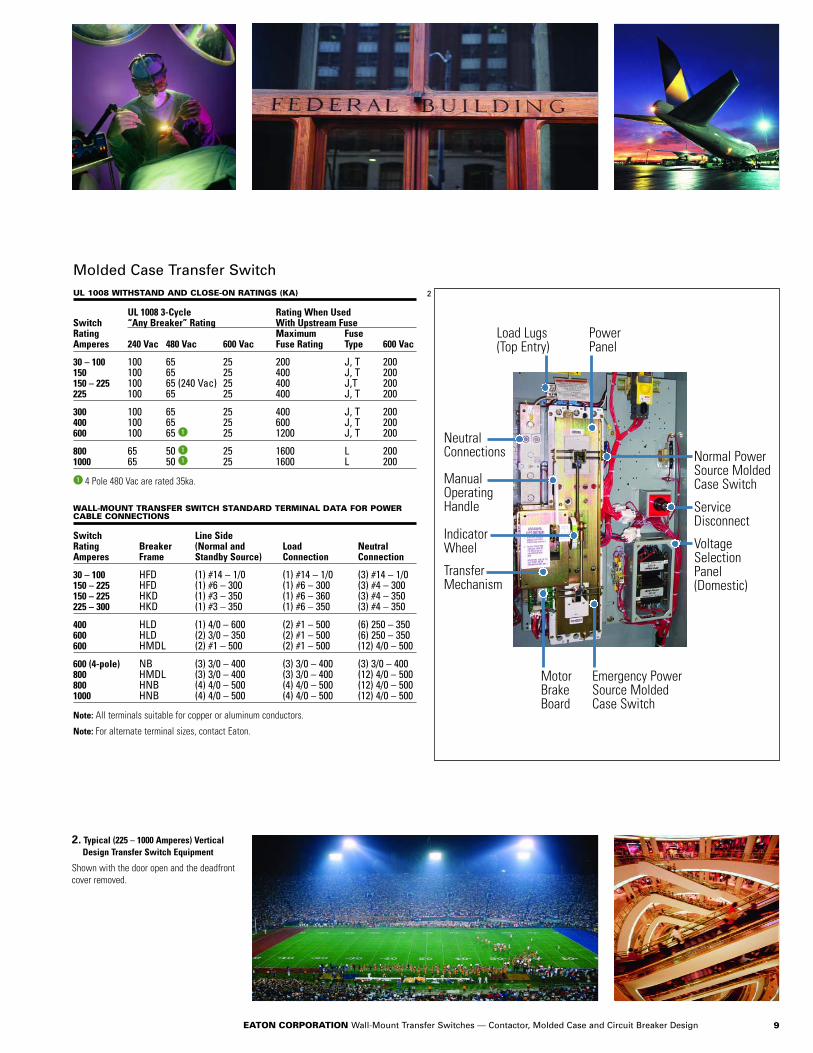
UL 1008 WITHSTAND AND CLOSE-ON RATINGS (KA)
UL 1008 3-Cycle Rating When UsedSwitch “Any Breaker” Rating With Upstream FuseRating Maximum FuseAmperes 240 Vac 480 Vac 600 Vac Fuse Rating Type 600 Vac
30 – 100 100 65 25 200 J, T 200150 100 65 25 400 J, T 200150 – 225 100 65 (240 Vac) 25 400 J,T 200225 100 65 25 400 J, T 200
300 100 65 25 400 J, T 200400 100 65 25 600 J, T 200600 100 65 1 25 1200 J, T 200
800 65 50 1 25 1600 L 2001000 65 50 1 25 1600 L 200
1 4 Pole 480 Vac are rated 35ka.
Molded Case Transfer Switch
WALL-MOUNT TRANSFER SWITCH STANDARD TERMINAL DATA FOR POWERCABLE CONNECTIONS
Switch Line SideRating Breaker (Normal and Load NeutralAmperes Frame Standby Source) Connection Connection
30 – 100 HFD (1) #14 – 1/0 (1) #14 – 1/0 (3) #14 – 1/0150 – 225 HFD (1) #6 – 300 (1) #6 – 300 (3) #4 – 300150 – 225 HKD (1) #3 – 350 (1) #6 – 360 (3) #4 – 350225 – 300 HKD (1) #3 – 350 (1) #6 – 350 (3) #4 – 350
400 HLD (1) 4/0 – 600 (2) #1 – 500 (6) 250 – 350600 HLD (2) 3/0 – 350 (2) #1 – 500 (6) 250 – 350600 HMDL (2) #1 – 500 (2) #1 – 500 (12) 4/0 – 500
600 (4-pole) NB (3) 3/0 – 400 (3) 3/0 – 400 (3) 3/0 – 400800 HMDL (3) 3/0 – 400 (3) 3/0 – 400 (12) 4/0 – 500800 HNB (4) 4/0 – 500 (4) 4/0 – 500 (12) 4/0 – 5001000 HNB (4) 4/0 – 500 (4) 4/0 – 500 (12) 4/0 – 500
Note: All terminals suitable for copper or aluminum conductors.
Note: For alternate terminal sizes, contact Eaton.
2. Typical (225 – 1000 Amperes) Vertical Design Transfer Switch Equipment
Shown with the door open and the deadfrontcover removed.
Load Lugs(Top Entry)
NeutralConnections
ManualOperatingHandle
IndicatorWheel
TransferMechanism
MotorBrakeBoard
PowerPanel
Normal PowerSource MoldedCase Switch
ServiceDisconnect
VoltageSelection Panel(Domestic)
Emergency PowerSource MoldedCase Switch
2
9EATON CORPORATION Wall-Mount Transfer Switches — Contactor, Molded Case and Circuit Breaker Design

AT V 3 KD A 3 0400 X S U
Type
AT = Automatic
Orientation
= Horizontal = Vertical = Contactor
Frame Size (Amperes)
Molded Case Device 1C2 = 2-Position
ContactorFD = 30 – 150KD = 225 – 300LD = 400MD = 600NB = 800 – 1000
Logic
1 = ATC-1003 = ATC-300I = ATC-600
Switch Number of Poles
2 = 2-Pole3 = 3-Pole4 = 4-Pole
Certification
U = UL ListedR = UL RecognizedX = No Listing
Enclosure
K = OpenS = NEMA 1J = NEMA 12R = NEMA 3R
Voltage
A = 120 V, 60 HzB = 208 V, 60 HzE = 600 V, 60 HzG = 220 V, 50/60 HzH = 380 V, 50 HzK = 600 V, 50 HzM = 230 V, 50 HzN = 401 V, 50 HzO = 415 V, 50 HzW = 240 V, 60 HzX = 480 V, 60 HzZ = 365 V, 50 Hz
Amperes 2
0030 = 30 A0070 = 70 A0100 = 100 A0150 = 150 A0200 = 200 A0225 = 225 A0320 = 320 A0300 = 300 A0400 = 400 A0600 = 600 A0800 = 800 A1000 = 1000 A
INDUSTRIAL MOLDED CASE TRANSFER SWITCH CATALOG NUMBERING SYSTEM
HVC
A = S1 (MCS) S2 (MCS)B = S1 (MCB) S2 (MCB)C = S1 (MCB) S2 (MCS)D = S1 (MCS) S2 (MCB)X = Fix Mount Contactor
BG
AH
C
FTop of Lugs
on Power Panel
LogicPanel
D
EPowerPanel
GutterSpace
TransformerPanel
1 HFD = 200 and 225 amperes, HLD = 600 amperes, HMD = 800 amperes for 240/120 Vac single-phase, 3-wire and 20Y/120 Vac 3-phase, 4-wire systems only.
2 The Contactor-Based Transfer Switch is currently available in 100, 200, 320, 400 and 600 amperes only. Contact the factory for availability on the 800, 1000 and 1200 ampere switch.
Note: MCB = Molded Case Breaker, MCS = Molded Case Switch.
10 EATON CORPORATION Wall-Mount Transfer Switches — Contactor, Molded Case and Circuit Breaker Design
CONTACTOR-BASED AND MOLDED CASE TRANSFER SWITCHES — DIMENSIONS IN INCHES (MM) AND APPROXIMATE SHIPPING IN LBS (KG)
SwitchRating Switch Enclosure Gutter Space Bolt Pattern Standard Terminals WeightAmperes Type A (Height) B (Width) C (Depth) D (Width) E (Depth) G (Horizontal) H (Vertical) Line Side (Normal Load Neutral Lbs. (kg)
& Standby Source) Connection Connection
Contactor-Based
100 — 35.61 (904.5) 20.06 (509.5) 11.34 (288.0) 2.00 (51.0) 5.00 (127.0) 10.25 (260.4) 34.73 (882.1) (1) #14 – 2/0 (1) #14 – 2/0 (3) #14 – 2/0 156 (71)
200 — 35.61 (904.5) 20.06 (509.5) 11.34 (288.0) 2.00 (51.0) 5.00 (127.0) 10.25 (260.4) 34.73 (882.1) (1) #6 – 250 1 (1) #6 – 250 1 (3) 1/0 – 250 160 (73)
320 — 53.00 (1346.2) 25.81 (655.6) 16.72 (425.0) 4.00 (101.0) 12.00 (304.0) 16.00 (406.4) 50.48 (1282.2) (1) #4/0 – 600 (1) #4/0 – 600 (6) 250 – 500 244 (111)(2) 1/0 – 250 (2) 1/0 – 250 (12) 4/0 – 500
(9) 500 – 750
400 — 53.00 (1346.2) 25.81 (655.6) 16.72 (425.0) 4.00 (101.0) 12.00 (304.0) 16.00 (406.4) 50.48 (1282.2) (1) #4/0 – 600 (1) #4/0 – 600 1 (6) 250 – 500 244 (111)(2) 1/0 – 250 (2) 1/0 – 250 (12) 4/0 – 500
(9) 500 – 750
600 — 64.00 (1625.6) 25.81 (655.6) 16.72 (425.0) 3.00 (76.0) 9.00 (228.0) 16.00 (406.4) 61.48 (1561.6) (2) #2 – 600 1 (2) #2 – 600 1 (12) 4/0 – 500 395 (179)(9) 500 – 750
Molded Case
30 – 100 HFD 2 47.74 (1213.0) 20.81 (528.6) 15.22 (387.0) 8.00 (203.2) 4.00 (101.6) 10.75 (273.0) 46.44 (1180.0) — — — 232 (105)150 – 225 HFD 2 47.74 (1213.0) 20.81 (528.6) 15.22 (387.0) 8.00 (203.2) 4.00 (101.6) 10.75 (273.0) 46.44 (1180.0) — — — 232 (105)30 – 100 HFD 3 47.74 (1213.0) 20.81 (528.6) 15.22 (387.0) 8.00 (203.2) 4.00 (101.6) 10.75 (273.0) 46.44 (1180.0) — — — 240 (109)
150 HFD 3 47.74 (1213.0) 20.81 (528.6) 15.22 (387.0) 8.00 (203.2) 4.00 (101.6) 10.75 (273.0) 46.44 (1180.0) — — — 240 (109)150 – 225 HFD 2 35.61 (904.0) 20.06 (509.5) 11.34 (288.0) 8.00 (203.2) 4.00 (101.6) 10.75 (273.0) 34.31 (904.0) — — — 150 (68)150 – 225 HKD 48.00 (1219.2) 20.81 (528.6) 16.65 (423.0) 8.00 (203.2) 4.00 (101.6) 11.00 (279.4) 45.50 (1155.7) — — — 305 (138)300 HKD 56.00 (1422.4) 20.81 (528.6) 16.65 (423.0) 8.00 (203.2) 4.00 (101.6) 11.00 (279.4) 53.50 (1358.9) — — — 295 (134)
400 HLD 4 53.00 (1346.0) 25.81 (655.6) 16.65 (423.0) 8.00 (203.2) 4.00 (101.6) 16.00 (406.4) 50.48 (1282.2) — — — 395 (179)400 HLD 64.00 (1625.6) 25.81 (655.6) 16.65 (423.0) 8.00 (203.2) 4.00 (101.6) 16.00 (406.4) 61.48 (1561.6) — — — 425 (193)600 HLD 2 64.00 (1625.6) 25.81 (655.6) 16.65 (423.0) 8.00 (203.2) 4.00 (101.6) 16.00 (406.4) 62.50 (1588.0) — — — 475 (215)600 HMDL 76.74 (1949.2) 25.81 (655.6) 17.75 (451.0) 8.00 (203.2) 4.00 (101.6) 16.00 (406.4) 75.15 (1908.8) — — — 480 (218)
800 HMDL 2 76.74 (1949.2) 25.81 (655.6) 17.75 (451.0) 8.00 (203.2) 4.00 (101.6) 16.00 (406.4) 75.15 (1908.8) — — — 510 (231)800 – 1000 HNB 76.74 (1949.2) 25.81 (655.6) 17.75 (451.0) 8.00 (203.2) 4.00 (101.6) 16.00 (406.4) 75.15 (1908.8) — — — 540 (245)
1 Suitable with copper only. 2 240/120 volt, single-phase, 3-wire or 208 volt, 3-phase, 4-wire systems only. 3 With multi-tap voltage selection panel. 4 Requires special line terminals.
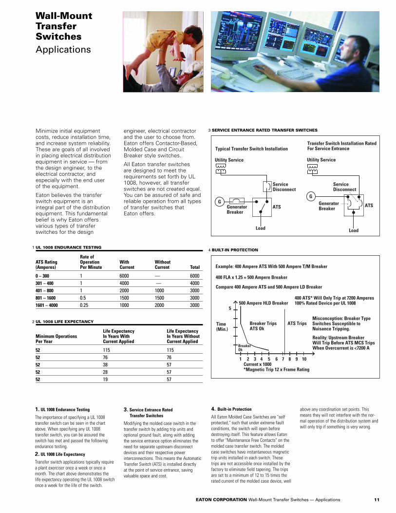
Minimize initial equipmentcosts, reduce installation time,and increase system reliability.These are goals of all involvedin placing electrical distributionequipment in service — fromthe design engineer, to theelectrical contractor, and especially with the end user of the equipment.
Eaton believes the transferswitch equipment is an integral part of the distributionequipment. This fundamentalbelief is why Eaton offers various types of transferswitches for the design
engineer, electrical contractorand the user to choose from.Eaton offers Contactor-Based,Molded Case and CircuitBreaker style switches.
All Eaton transfer switches are designed to meet therequirements set forth by UL1008, however, all transferswitches are not created equal.You can be assured of safe andreliable operation from all typesof transfer switches that Eaton offers.
Wall-MountTransferSwitchesApplications
1. UL 1008 Endurance Testing
The importance of specifying a UL 1008transfer switch can be seen in the chartabove. When specifying any UL 1008 transfer switch, you can be assured theswitch has met and passed the followingendurance testing.
2. UL 1008 Life Expectancy
Transfer switch applications typically requirea plant exerciser once a week or once amonth. The chart above demonstrates thelife expectancy operating the UL 1008 switchonce a week for the life of the switch.
UL 1008 ENDURANCE TESTING
Rate ofATS Rating Operation With Without(Amperes) Per Minute Current Current Total
0 – 300 1 6000 — 6000301 – 400 1 4000 — 4000401 – 800 1 2000 1000 3000801 – 1600 0.5 1500 1500 30001601 – 4000 0.25 1000 2000 3000
1
UL 1008 LIFE EXPECTANCY
Life Expectancy Life ExpectancyMinimum Operations In Years With In Years Without Per Year Current Applied Current Applied
52 115 11552 76 7652 38 5752 28 5752 19 57
2
SERVICE ENTRANCE RATED TRANSFER SWITCHES
GeneratorBreaker
G
Load
ServiceDisconnect
ATS
Utility Service
GGeneratorBreaker
Load
ATS
ServiceDisconnect
Utility Service
Typical Transfer Switch InstallationTransfer Switch Installation RatedFor Service Entrance
3
4. Built-in Protection
All Eaton Molded Case Switches are "selfprotected," such that under extreme faultconditions, the switch will open beforedestroying itself. This feature allows Eatonto offer "Maintenance Free Contacts" on themolded case transfer switch. The moldedcase switches have instantaneous magnetictrip units installed in each switch. Thesetrips are not accessible once installed by thefactory to eliminate field tapering. The tripsare set to a minimum of 12 to 15 times therated current of the molded case device, well
above any coordination set points. Thismeans they will not interfere with the nor-mal operation of the distribution system andwill only trip if something is very wrong.
BUILT-IN PROTECTION
400 FLA x 1.25 = 500 Ampere Breaker
Compare 400 Ampere ATS and 500 Ampere LD Breaker
Time(Min.)
5
1 2 3 4 5 6 7 8 9 10
BreakerOk
400 ATS* Will Only Trip at 7200 Amperes100% Rated Device per UL 1008
Breaker TripsATS Ok
ATS Trips
500 Ampere HLD Breaker
Current x 1000*Magnetic Trip 12 x Frame Rating
Misconception: Breaker TypeSwitches Susceptible to Nuisance Tripping.
Example: 400 Ampere ATS With 500 Ampere T/M Breaker
Reality: Upstream Breaker Will Trip Before ATS MCS Trips When Overcurrent is <7200 A
4
11EATON CORPORATION Wall-Mount Transfer Switches — Applications
3. Service Entrance Rated Transfer Switches
Modifying the molded case switch in thetransfer switch by adding trip units andoptional ground fault, along with adding the service entrance option eliminates theneed for separate upstream disconnectdevices and their respective power interconnections. This means the AutomaticTransfer Switch (ATS) is installed directly at the point of service entrance, saving valuable space and cost.

© 2007 Eaton CorporationAll Rights ReservedPrinted in USAPublication No. BR01600001E / GGD2021March 2007
Eaton CorporationElectrical Group1000 Cherrington ParkwayMoon Township, PA 15108United States877-ETN CARE (877-386-2273)Eaton.com
Cutler-Hammer is a federally registered trademark of Eaton Corporation. NEMA is the registered trademark and service mark of the National Electrical ManufacturersAssociation. UL is a federally registeredtrademark of Underwriters Laboratories Inc.National Electrical Code and NEC are registered trademarks of the National FireProtection Association, Quincy, Mass. CSA is a registered trademark of theCanadian Standards Association. BOCA is a registered trademark of Building Officialsand Code Administrators International, Inc.Uniform Building Code (UBC) is a trademarkof the International Conference of BuildingOfficials (ICBO).
Eaton’s electrical business is a global leader in electrical control, power distribution, uninterruptible power supply and industrial automation products and services. Eaton’s global electrical brands, including Cutler-HammerT, PowerwareT, HolecT and MEMT, provide customer-driven PowerChainManagement™ solutions to serve the power system needs of the industrial, institutional, government, utility, commercial, residential, IT, mission critical and OEM markets worldwide.
Eaton Corporation is a diversified industrial manufacturer with 2006 sales of $12.4 billion. Eaton is a global leader in electrical systems and components for power quality, distribution and control; fluid power systems and services for industrial, mobile and aircraft equipment; intelligent truck drivetrain systems for safety and fuel economy; and automotive engine air managementsystems, powertrain solutions and specialty controls for performance, fuel economy and safety. Eaton has 60,000 employeesand sells products to customers in more than 125 countries. For more information, visit www.eaton.com.